Socket Mobile BTM-2 KwikBlue Bluetooth Module User Manual HIS 2 ASIC Specification
Socket Mobile, Inc. KwikBlue Bluetooth Module HIS 2 ASIC Specification
Manual revised

KwikBlue Module Development Kit
Installation Guide
Revision 1.04
April 23, 2004

KwikBlue Module Development Kit Installation Guide
Reproduction of the contents of this manual without the permission of Socket Communications is
expressly prohibited.
Please be aware that the product described in this manual may change without notice.
This manual has been prepared with the greatest care regarding its contents. However, in the event that it
contains omissions, errors or any other misinformation, please feel free to direct comments to:
Embedded Systems Group (ESG)
Socket Communications, Inc.
37400 Central Court
Newark, CA 94560
You are also welcome to call Socket Communications at (510) 744-2700, FAX inquiries to (510) 744-
2727, or you may send an e-mail to ESG@Socketcom.com. Information on Socket products can also be
obtained from our web site at: www.socketcom.com.
This product is covered by Part I (EU-VO Nr.1334/2000). The export of goods covered by Part I of the
Export List is subject to licensing (Article 3 EU regulation, Section 5 AWV).
Other than the above, Socket Communications can assume no responsibility for anything resulting from
the application of information contained in this manual.
April 23, 2004 Copyright © 2003-2004 Socket Communications, Inc. Page ii
Document#: 6410-00215-C CONFIDENTIAL Revision 1.04

KwikBlue Module Development Kit Installation Guide
Regulatory Compliance
The KwikBlue-1 Class 1 Module using Bluetooth wireless technology complies with Part 15 of the FCC
Rules. Operation is subject to the following two conditions: (1) this device may not cause harmful
interference, and (2) this device must accept any interference received, including interference that may
cause undesired operation.
This equipment has been tested and found to comply with the limits for a Class A digital device, pursuant
to Part 15 of the FCC Rules. These limits are designed to provide reasonable protection against harmful
interference when the equipment is operated in a commercial environment. This equipment generates,
uses, and can radiate radio frequency energy and, if not installed and used in accordance with the
instruction manual, may cause harmful interference to radio communications. Operation of this equipment
in a residential area is likely to cause harmful interference in which case the user will be required to
correct the interference at their own expense.
This equipment generates and radiates radio-frequency energy. To comply with FCC RF exposure
compliance requirements, the following antenna installation and device operation configurations must be
satisfied: (1) Users are not permitted to make changes or modify the system in any way, and (2)
connecting external antennas to the card is prohibited. Changes or modifications not expressly approved
by the party responsible for compliance could void the user’s authority to operate the equipment.
NOTE: For end-users of the KwikBlue-1 Class 1 Module, the FCC ID# LUBBTM-2 must be displayed
on the outside of the host, i.e., “Contains FCC ID: LUBBTM-2.”
April 23, 2004 Copyright © 2003-2004 Socket Communications, Inc. Page iii
Document#: 6410-00215-C CONFIDENTIAL Revision 1.04

KwikBlue Module Development Kit Installation Guide
Copyright and Trademarks
The Bluetooth® word mark and logos are owned by the Bluetooth SIG, Inc. and any use of such marks by
Socket Communications is under license.
Socket Communications and ® are registered trademarks of Socket Communications, Inc.
KwikBlue is a trademark of Socket Communications, Inc.
April 23, 2004 Copyright © 2003-2004 Socket Communications, Inc. Page iv
Document#: 6410-00215-C CONFIDENTIAL Revision 1.04

KwikBlue Module Development Kit Installation Guide
Table of Contents
1. Overview .............................................................................................................................................1
2. Hardware Description........................................................................................................................2
2.1. KwikBlue-1 (Class 1) Module – Top View.....................................................................................2
2.2. KwikBlue-2 (Class 2) Module – Top View.....................................................................................3
2.3. Bottom View of KwikBlue Module.................................................................................................3
2.4. KwikBlue Module Development Board ..........................................................................................4
2.5. Optional CODEC Board ..................................................................................................................5
3. System Requirements.........................................................................................................................6
3.1. KwikBlue-1 Development Hardware Requirements .......................................................................6
3.2. KwikBlue-2 Development Hardware Requirements .......................................................................6
3.3. Optional CODEC Audio Board .......................................................................................................6
3.4. WinCE or Local Host Software Requirements................................................................................6
3.5. User-Supplied Local Host Software Requirements .........................................................................6
4. Desktop Test Set-up ...........................................................................................................................7
5. Hardware Configuration.................................................................................................................10
5.1. Module Baud Rate Configuration..................................................................................................10
5.2. Firmware Upgrade .........................................................................................................................10
6. WinCE Test Setup............................................................................................................................11
7. HCI Test Setup.................................................................................................................................12
7.1. Test 1 - Devices with Compact Flash or PC Card Slots ................................................................12
7.2. Test 2 - KwikBlue Module (or Dev Board) Hard-Wired to Serial Port.........................................14
8. Suspend\Resume...............................................................................................................................17
9. Bluetooth Driver List .......................................................................................................................17
10. Certification Testing Utilities..........................................................................................................18
11. KwikBlue Development Board Jumpers........................................................................................18
12. Audio CODEC Setup (Optional) ....................................................................................................19
13. KwikBlue Development Board Bill of Materials (BOM)..............................................................20
14. CODEC Board Bill of Materials (BOM)........................................................................................21
15. Errata ................................................................................................................................................22
16. Appendix A: BC01 vs. BC02 Pin Assignments.............................................................................23
April 23, 2004 Copyright © 2003-2004 Socket Communications, Inc. Page v
Document#: 6410-00215-C CONFIDENTIAL Revision 1.04

KwikBlue Module Development Kit Installation Guide
List of Tables
Table 1: KwikBlue-2 Module Features List ................................................................................................. 2
Table 2: KwikBlue-2 Module Features List ................................................................................................. 3
Table 3: KwikBlue Development Board Jumpers ...................................................................................... 18
Table 4: KwikBlue Development Board Bill of Materials ......................................................................... 20
Table 5: CODEC Board Bill of Materials................................................................................................... 21
Table 6: BC01 vs. BC02 Pin Assignments ................................................................................................. 23
Table 7: BC01 Class 1 Module Pin Assigments......................................................................................... 24
Table 8: BC02 Class 2 Module Pin Assignments....................................................................................... 25
Table 9: BC02 Class 1 Module Pin Assignments....................................................................................... 26
April 23, 2004 Copyright © 2003-2004 Socket Communications, Inc. Page vi
Document#: 6410-00215-C CONFIDENTIAL Revision 1.04

KwikBlue Module Development Kit Installation Guide
List of Figures
Figure 1: Top View of the KwikBlue-1 Module........................................................................................... 2
Figure 2: Top View of the KwikBlue-2 Module........................................................................................... 3
Figure 3: Bottom View of the KwikBlue Module ........................................................................................ 3
Figure 4: KwikBlue Development Board ..................................................................................................... 4
Figure 5: Optional CODEC Board................................................................................................................ 5
Figure 6: Desktop Test - KwikBlue Development Board Set-up ................................................................. 7
Figure 7: HCI Test - KwikBlue Development Board Set-up...................................................................... 13
Figure 8: Optional Audio CODEC Board Setup......................................................................................... 19
April 23, 2004 Copyright © 2003-2004 Socket Communications, Inc. Page vii
Document#: 6410-00215-C CONFIDENTIAL Revision 1.04

KwikBlue Module Development Kit Installation Guide
1. Overview
Socket offers the fully-supported KwikBlue Module Development Kit to aid developers incorporating
Bluetooth® wireless technology into their product designs. This is a development and interface kit,
providing a reference for Socket’s small form factor KwikBlue Module which is mounted on a versatile
adapter board, allowing the module to communicate via an RS-232 serial interface. There is also an
optional CODEC board which supports the development of Bluetooth audio solutions. The Module Dev
Kit is compatible with the Windows CE operating system.
The KwikBlue Module utilizes the Cambridge Silicon Radio (CSR) BC02 chipset and comes in a
standard carrier module format which is a highly-integrated small footprint board-to-board connectible
package. The Module is also available as a Surface Mount Device (SMD) for custom applications.
The term “KwikBlue-1” refers to the Class 1 version of Socket’s carrier module using Bluetooth wireless
technology which transmits data up to 100 meter/300 feet. The term “KwikBlue-2” refers to the Class 2
version of Socket’s carrier module using Bluetooth wireless technology which transmits data up to 10
meter/30 feet.
NOTE: The SMD module version is described in the “KwikBlue SMD Module Specification” (Socket
document P/N 6410-00195), located on the KwikBlue Dev Kit 008D CD (Socket P/N 6230-00008-D).
April 23, 2004 Copyright © 2003-2004 Socket Communications, Inc. Page 1
Document#: 6410-00215-C CONFIDENTIAL Revision 1.04
KwikBlue Module Development Kit Installation Guide
2. Hardware Description
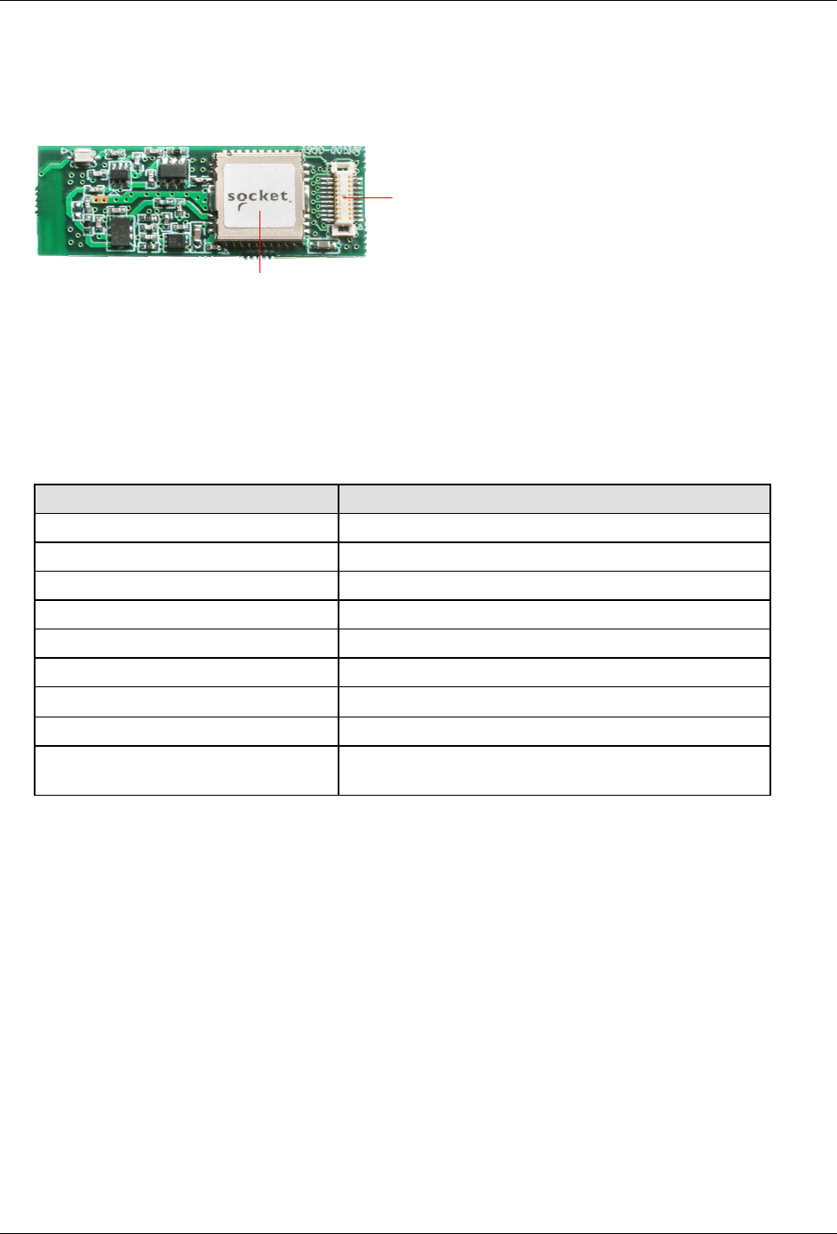
2.1. KwikBlue-1 (Class 1) Module – Top View
Figure 1: Top View of the KwikBlue-1 Module
The KwikBlue-1 Module contains CSR’s BC2-EXT (BC02) chipset which has a complete transceiver
radio and baseband controller section: 16 bit RISC processor, RAM and Flash memory. Also built in
are a high- accuracy reference oscillator and a subclock for managing power to extremely low levels.
Protocol software is already downloaded into the integrated Flash memory and it interfaces to the
HCI layer of the upper layer protocol stack on an appropriate host system.
20-pin Connector
Class 1 SMD Bluetooth Module
Features Values
Carrier Module Dimensions 35.0 x 12.0 x 2.8 mm (height above PCB)
Power Level +16 dBm Max.
Program Memory 4 Mbits (256k bytes x 16 bits) Flash
RAM 32k bytes x 16 bits
Reference Oscillator Built-in
Sub Clock Oscillator Built-in
Audio Interface PCM A-Law, µ-Law (CVSD)
Serial Data Interface UART (BCSP)
Physical Connection Board-to-board connector:
Matsushita Electric Works AXK6F20345
Table 1: KwikBlue-2 Module Features List
April 23, 2004 Copyright © 2003-2004 Socket Communications, Inc. Page 2
Document#: 6410-00215-C CONFIDENTIAL Revision 1.04
KwikBlue Module Development Kit Installation Guide
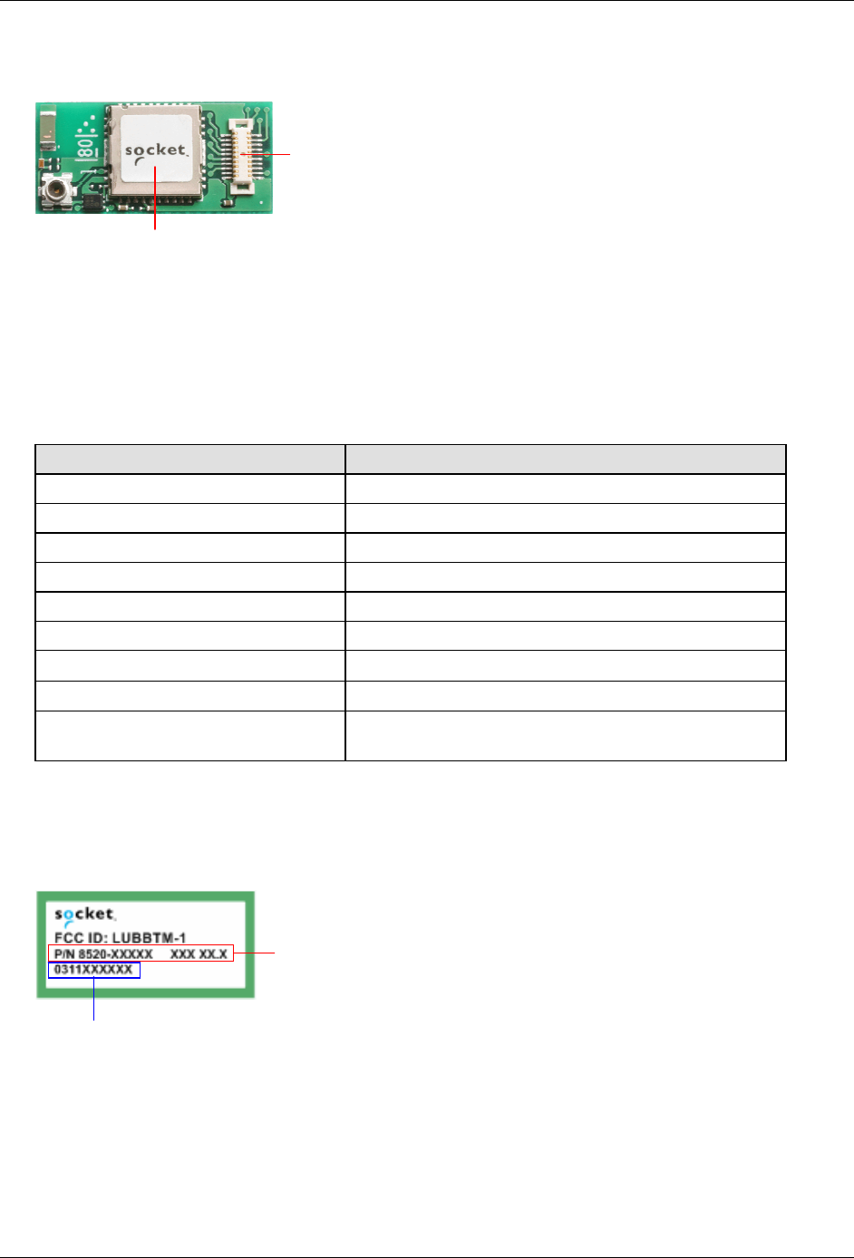
2.2. KwikBlue-2 (Class 2) Module – Top View
Figure 2: Top View of the KwikBlue-2 Module
The KwikBlue-2 Module contains CSR’s BC2-EXT (BC02) chipset which has a complete transceiver
radio and baseband controller section: 16 bit RISC processor, RAM and Flash memory. Also built in
are a high- accuracy reference oscillator and a subclock for managing power to extremely low levels.
Protocol software is already downloaded into the integrated Flash memory and it interfaces to the
HCI layer of the upper layer protocol stack on an appropriate host system.
Features Values
Carrier Module Dimensions 25.0 x 12.0 x 2.9 mm
Power Level +4 dBm Max.
Program Memory 4 Mbits (256k bytes x 16 bits) Flash
RAM 32k bytes x 16 bits
Reference Oscillator Built-in
Sub Clock Oscillator Built-in
Audio Interface PCM A-Law, µ-Law (CVSD)
Serial Data Interface UART (BCSP)
Physical Connection Board-to-board connector:
Matsushita Electric Works AXK6F20345
Table 2: KwikBlue-2 Module Features List
2.3. Bottom View of KwikBlue Module
Figure 3: Bottom View of the KwikBlue Module
Socket part number; firmware version
20-pin Connector
Class 2 SMD Bluetooth Module
Date code: YYMMxxxxxx
April 23, 2004 Copyright © 2003-2004 Socket Communications, Inc. Page 3
Document#: 6410-00215-C CONFIDENTIAL Revision 1.04
KwikBlue Module Development Kit Installation Guide
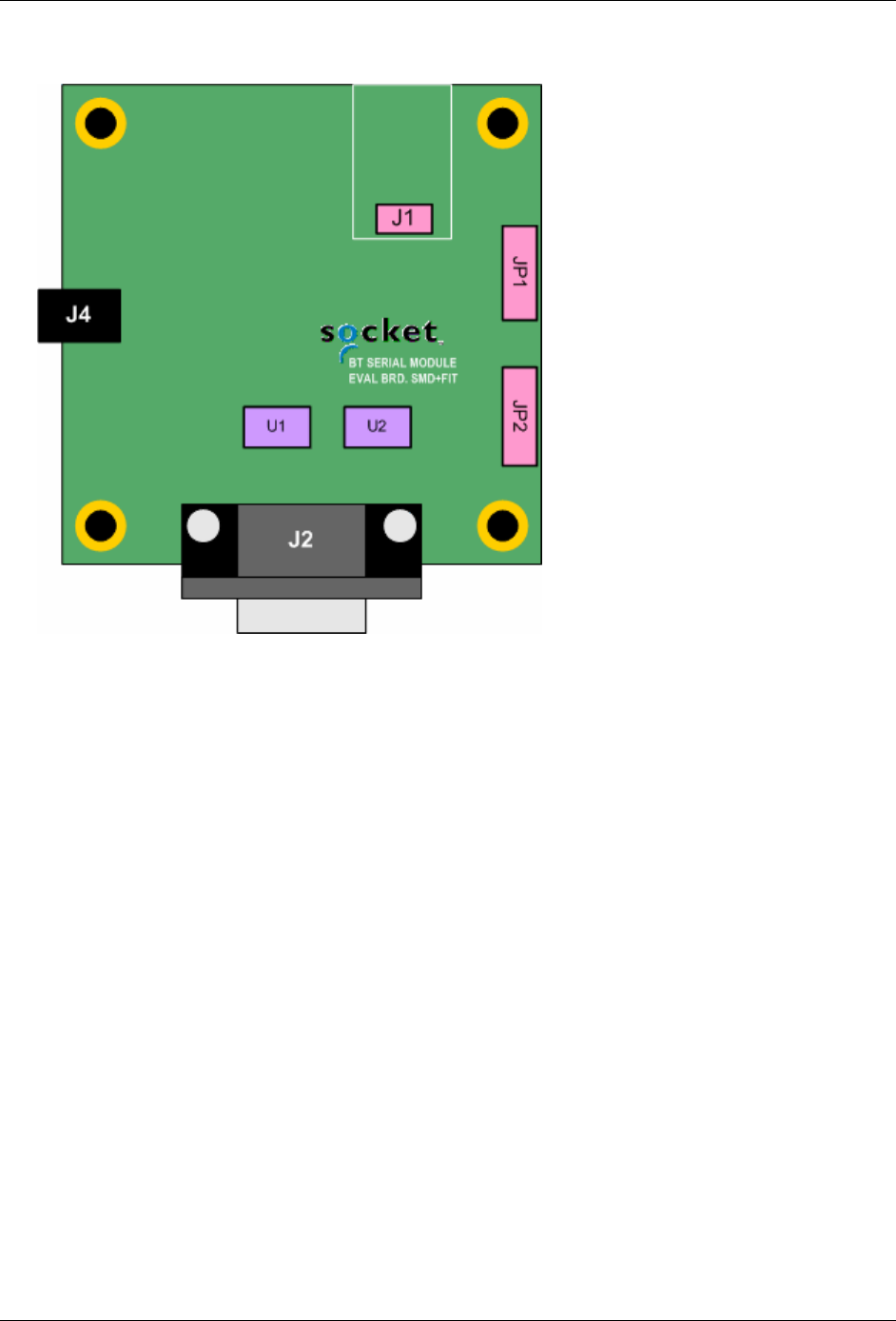
2.4. KwikBlue Module Development Board
Figure 4: KwikBlue Development Board
The KwikBlue Module Development Board includes the following features:
Connector J1 support for KwikBlue-1 or KwikBlue-2 Modules.
RS 232 serial port with 9-pin right angle D-type male connector (J2)
Power jack connector for 5 VDC power adapter (J4)
April 23, 2004 Copyright © 2003-2004 Socket Communications, Inc. Page 4
Document#: 6410-00215-C CONFIDENTIAL Revision 1.04
KwikBlue Module Development Kit Installation Guide
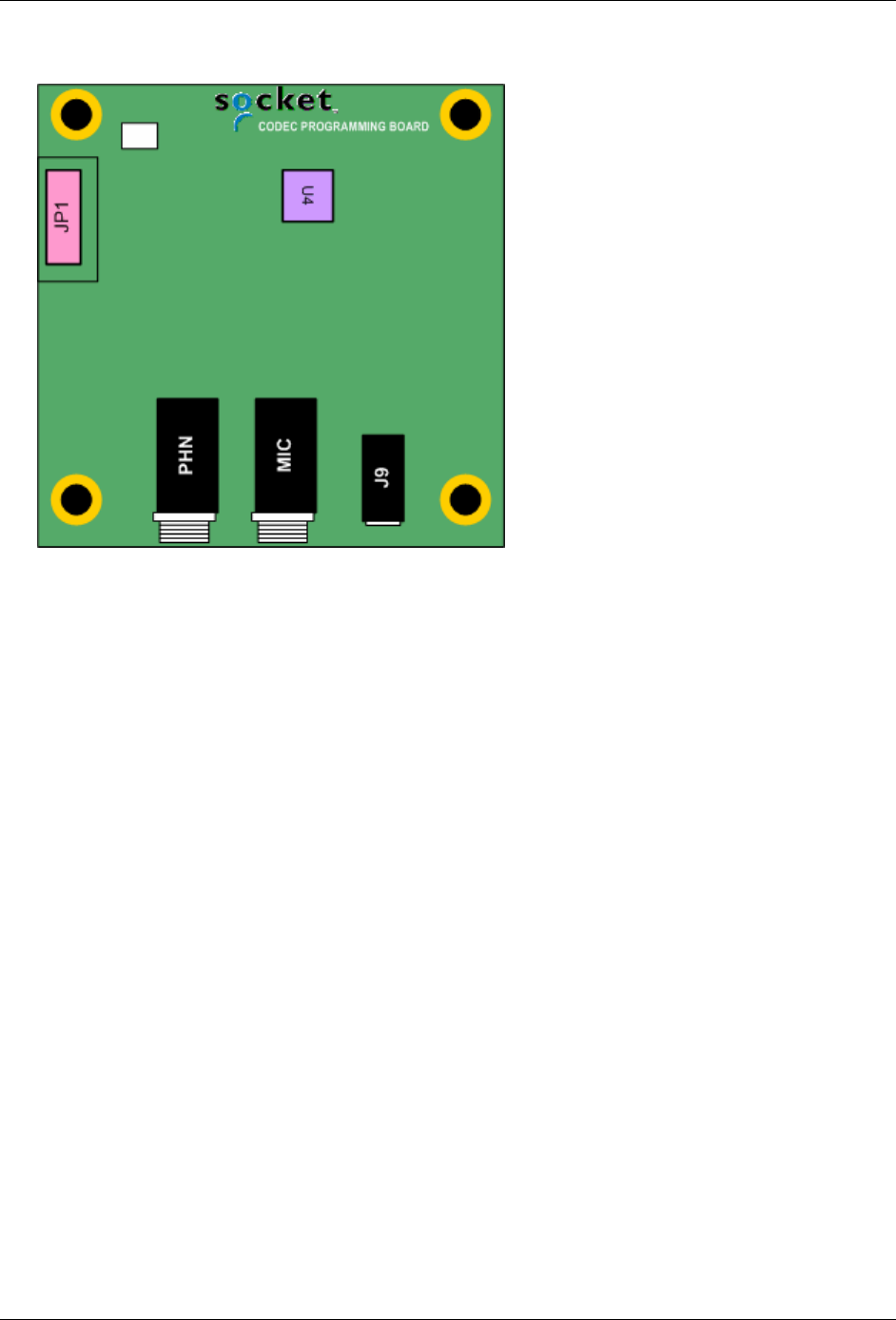
2.5. Optional CODEC Board
Figure 5: Optional CODEC Board
This optional board provides an interface to the industry standard Motorola MC145483 telephone
quality CODEC. The CODEC board has the following features:
2.5 mm jack for microphone/line-in (MIC)
2.5 mm jack for speaker/line-out (PHN)
3.5 mm combination microphone speaker jack (J9)
Note: the speaker output is designed to drive a 700 ohm or greater load.
Please refer to the MC145483 data sheet for more information.
April 23, 2004 Copyright © 2003-2004 Socket Communications, Inc. Page 5
Document#: 6410-00215-C CONFIDENTIAL Revision 1.04

KwikBlue Module Development Kit Installation Guide
3. System Requirements
3.1. KwikBlue-1 Development Hardware Requirements
KwikBlue-1 Module to Module Development Kit (9010-00459)
(2) KwikBlue development boards (7010-00120)
(2) KwikBlue-1 Modules (8520-00080)
(2) Socket’s CF Ruggedized Serial I/O cards (8510-00115)
(2) PC Card to CF card adapters (8520-00031)
(2) 5 VDC power adapters (8530-00015)
(2) Null modem adapters (8520-00081)
Local hosts with PC Card/CF Slot
3.2. KwikBlue-2 Development Hardware Requirements
KwikBlue-2 Module to Module Development Kit (9010-00460)
(2) KwikBlue development boards (7010-00120)
(2) KwikBlue-2 Modules (8520-00069)
(2) Socket’s CF Ruggedized Serial I/O cards (8510-00115)
(2) PC Card to CF card adapters (8520-00031)
(2) 5 VDC power adapters (8530-00015)
(2) Null modem adapters (8520-00081)
Local hosts with PC Card/CF Slot
3.3. Optional CODEC Audio Board
CODEC Board (7010-00133)
Dev Board to CODEC cable (8100-00200)
3.4. WinCE or Local Host Software Requirements
Socket’s Bluetooth stack – WinCE
Socket’s test applications, PrintDemo – WinCE
CSR’s BlueSuite/BlueChat – WinCE and desktop
CSR’s BlueSuite/PSTool – desktop
CSR’s BlueSuite/BlueTest – desktop
3.5. User-Supplied Local Host Software Requirements
User-supplied Bluetooth stack
User-supplied function test applications
User-supplied radio test applications
April 23, 2004 Copyright © 2003-2004 Socket Communications, Inc. Page 6
Document#: 6410-00215-C CONFIDENTIAL Revision 1.04
KwikBlue Module Development Kit Installation Guide
4. Desktop Test Set-up
1) Install the Serial I/O high speed drivers from the Serial I/O High Speed Installation Disc to your
Windows 98/2K/XP system.
2) Install the BlueSuite software. This software must be installed on a system with a Compact Flash or
PC Card slot, such as a laptop. Run "BlueSuiteCasira_v1.18.exe" located on the KwikBlue Dev Kit
008D CD under “Utilities\CSR\BlueSuite.” Follow the installation instructions; the default install
location is “C:\Program Files\CSR\BlueSuite.” Read the information in"PSTool.txt" for further
instructions.
3) Reboot your system.
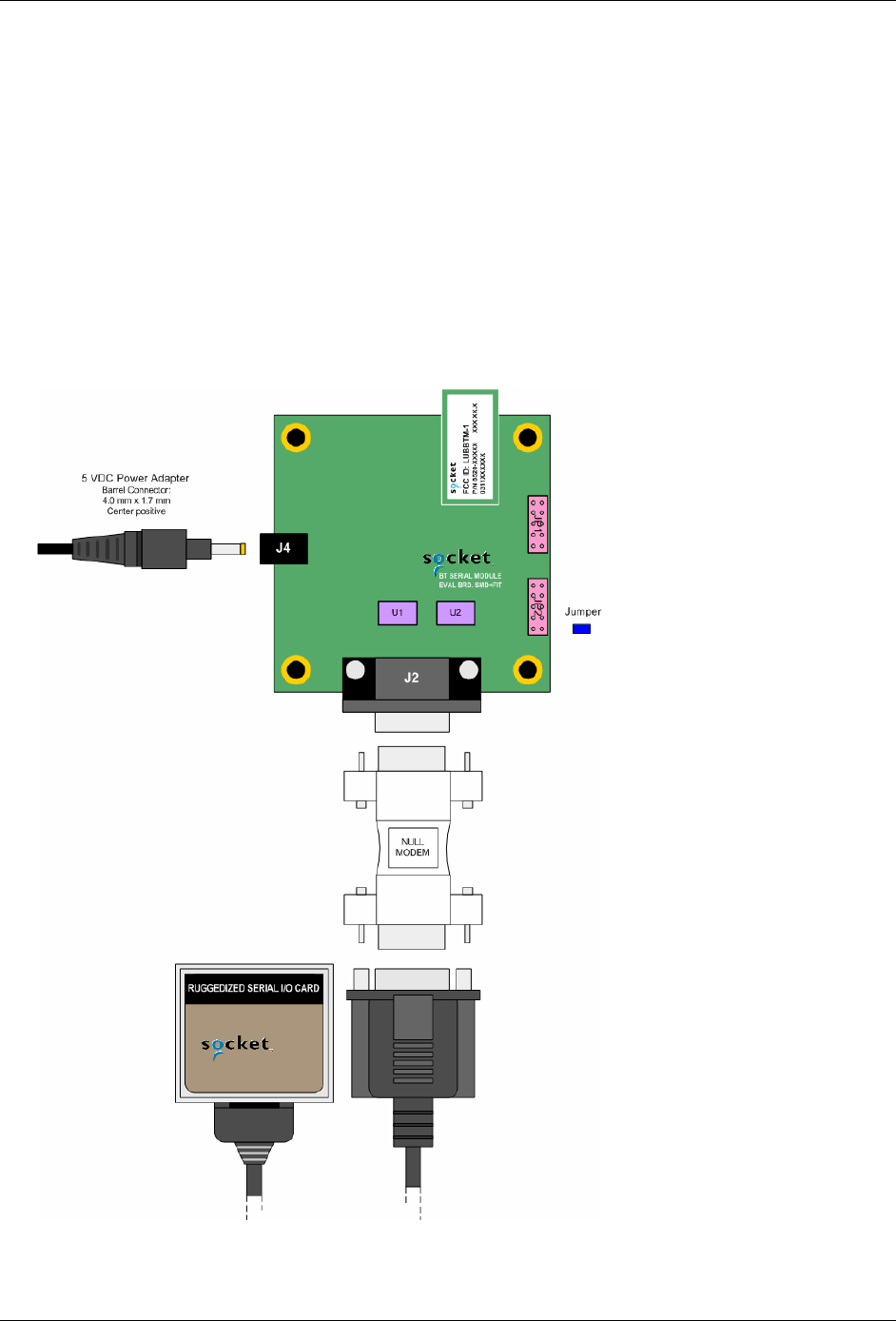
4) Assemble KwikBlue Development Board components (without optional CODEC board):
Figure 6: Desktop Test - KwikBlue Development Board Set-up
April 23, 2004 Copyright © 2003-2004 Socket Communications, Inc. Page 7
Document#: 6410-00215-C CONFIDENTIAL Revision 1.04

KwikBlue Module Development Kit Installation Guide
a. Insert jumper on JP2; default configuration is pins 1 to 2 for the KwikBlue Module. See Chapter
11, KwikBlue Development Board Jumpers for all jumper configurations.
b. Connect the null modem adapter to KwikBlue Dev Board connector J2.
c. Connect the CF Ruggedized Serial I/O (CF RIO) Card to the null modem adapter.
d. Connect the 5 VDC power supply to KwikBlue Dev Board connector J4.
5) Insert the CF RIO card into the CF/PC card slot of your system. A tray icon should appear indicating
the card is in use. Click on this once to show the COM number the CF RIO card is operating on (or
use My Computer, Device Manager).
6) Run the PSTOOL.exe utility (C:\Program Files\CSR\BlueSuite). Select BCSP and the COM port
number where the serial card is located. Click on BdAddr to verify the KwikBlue Module is being
read from. You should see a non-zero 16 byte hex number. The PSTOOL.exe utility can be used to
program the module parameters.
7) BlueChat2.exe: this program is available in both desktop and WinCE versions. The desktop version is
in the folder “C:\Program Files\CSR\BlueSuite” from the above install. The WinCE software can be
found on the KwikBlue Dev Kit 008D CD in the “\Utilities\CSR\BlueSuite\BlueSuite 118 CE” folder.
Desktop to Desktop: you must have two desktop systems and two development board assemblies set
up as described above running BlueChat2.exe. Select BCSP, the COM the serial card is on, and the
baud rate. Select the "Role" for one system as the Slave and the Role for the other system as the
Master.
Desktop to WinCE: copy and install the CSR WinCE BlueSuite software from the KwikBlue Dev Kit
008D CD folder “\Utilities\CSR\BlueSuite\BlueSuite 118 CE” to your WinCE device.
a. Using the CF RIO connected to KwikBlue Module:
If you have not completed the WinCE Test Set-up section, you can install the Socket high-speed
Serial Drivers from the Serial I/O High Speed Driver Installation Disc to your WinCE device.
If you have completed the WinCE Test Set-up section, you need to disable the Socket Bluetooth
stack from loading. This can be done by renaming the BCSPStack.dll in the \Windows directory.
After setting up the KwikBlue Dev Board, insert the CF RIO card into the CF/PC card slot of
your WinCE device. You can now run the BlueChat2.exe on the WinCE side. Select the "Role"
for one system as the Slave and the Role for the other system as the Master.
b. KwikBlue Module (or Dev Board) is hard-wired to serial port:
If you wish to embed the module with a high-speed-baud rate (greater than 115 Kbps), you must
have a UART (such as Socket’s CF or PC serial cards) that supports the higher baud rates. Refer
to Chapter 5.1, Module Baud Rate Configuration for setting the baud rate of the module.
BlueChat2.exe will communicate through the Serial driver on the COM that the KwikBlue
Module is connected to.
If you have completed the WinCE Test Set-up section, you need to disable the Socket Bluetooth
stack from loading. This can be done by renaming the BCSPStack.dll in the \Windows directory.
April 23, 2004 Copyright © 2003-2004 Socket Communications, Inc. Page 8
Document#: 6410-00215-C CONFIDENTIAL Revision 1.04

KwikBlue Module Development Kit Installation Guide
You can now run the BlueChat2.exe on the WinCE side. Select the "Role" for one system as the
Slave and the Role for the other system as the Master.
WinCE to WinCE test: you must have two WinCE systems set up as described above. Select
BCSP, the COM the serial card is on, and the baud rate. Select the "Role" for one system as the
Slave and the Role for the other system as the Master.
8) BlueTest.exe: BlueTest.exe is used to test various module functions. Select BCSP, the COM the
serial card is on, and the baud rate. Click on one of the "RF Test Mode" items such as TXSTART.
This will display a list of parameters in the "Test Arguments" window. This utility is used for
Bluetooth SIG and FCC conformance testing.
April 23, 2004 Copyright © 2003-2004 Socket Communications, Inc. Page 9
Document#: 6410-00215-C CONFIDENTIAL Revision 1.04

KwikBlue Module Development Kit Installation Guide
5. Hardware Configuration
5.1. Module Baud Rate Configuration
The default KwikBlue Module speed is 115200 bps. To use the high-speed driver (921600 bps), you
must have a high-speed UART (such as Socket’s CF or PC serial cards) that supports this speed and
the baud rate of the module must be re-programmed. Follow the software install instructions in the
“Desktop Test Set-up” section:
1. Click on the BdAddr to verify that the KwikBlue module is being read from. You should see a
non-zero 16 byte hex number.
2. Select UART_Baud_Rate - change the key to the value you wish to use. Select "Set" to write the
new value into firmware.
3. Power cycle the module for the new firmware changes to take effect.
5.2. Firmware Upgrade
If firmware upgrades become available, Socket support will assist you in updating your system if
necessary.
April 23, 2004 Copyright © 2003-2004 Socket Communications, Inc. Page 10
Document#: 6410-00215-C CONFIDENTIAL Revision 1.04

KwikBlue Module Development Kit Installation Guide
6. WinCE Test Setup
The information below pertains to Socket’s Bluetooth WinCE driver Versions - Drakar Stack Version
1.4.3.38 and previous. It does not apply to Drakar Stack Dev Version 1.4.4.0 and higher. The KwikBlue
module is available in two configurations: HCI and Virtual Machine (VM). The default factory delivery is
with a HCI stack interface. Please contact Socket for information on VM configurations since they are
typically custom configurations.
HCI (Host Controller Interface): the Bluetooth stack drivers are run under an OS (currently the
drivers are for the Windows CE OS).
Virtual Machine (VM): in this mode, a scaled-down version of the Bluetooth stack runs on the
KwikBlue module itself. The module can be programmed to run a small application. The module
does not need any other drivers.
April 23, 2004 Copyright © 2003-2004 Socket Communications, Inc. Page 11
Document#: 6410-00215-C CONFIDENTIAL Revision 1.04

KwikBlue Module Development Kit Installation Guide
7. HCI Test Setup
The following tests are set up for KwikBlue Modules to be used in an HCI configuration. In this
configuration, the Bluetooth stack drivers are run on a Windows CE device. The KwikBlue Module Dev
Kit provides support for Pocket PC 2000/2002/2003, HPC 2000 and CE .NET devices (CE .NET devices
are custom builds and may require factory support. Please contact Socket regarding these platforms). The
following processors are supported: ARM, ARMV4, ARMV4T, ARMV4i, MIPS and SH3.
7.1. Test 1 - Devices with Compact Flash or PC Card Slots
This test connects the CF Ruggedized Serial I/O (CF RIO) card with the KwikBlue Module Dev
Board and runs the Bluetooth drivers on a Windows CE device.
a) Bluetooth SDK Install: run Setup.exe from the Bluetooth_Stack_Dev_Tools_CR4.3.38 CD. This
will install the Bluetooth SDK files to your desktop in the folder 'C:\Drakar Stack Dev Files'. This
includes the WinCE Bluetooth stack and sample applications.
b) Bluetooth Driver Install: the Bluetooth driver is contained in a *.cab and can be copied to your
device via ActiveSync or through a storage card.
i) ActiveSync: once your device is ActiveSync'd to your desktop, run Setup.exe from:
C:\Drakar Stack Dev Files\Installs\Main Stack Release\Disk1\Setup.exe
Follow the on-screen instructions to install the Bluetooth drivers to your device.
ii) Storage Card: if your device does not support ActiveSync, you can manually copy the
Bluetooth *.cab to a storage card and install it to your device. The Bluetooth *.cab is
contained in the folder:
C:\Drakar Stack Dev Files\Installs\Main Stack Release\CABs
The *.cab name is in the form "BtStack.PlatformProcessor.Cab":
BtStack.CENETARMV4.CAB (CENET, ARMV4 processor, wide (HPC) screen layout)
BtStack.CENETPPCARMV4.CAB (CENET, ARMV4 processor, Pocket PC screen layout)
BtStack.CENETPPCARMV4T.CAB (CENET, ARMV4T processor, Pocket PC screen layout)
BtStack.HPC2000ARM.CAB
BtStack.HPC2000MIPS.CAB
BtStack.PPC2003ARMV4.CAB
BtStack.PPCARM.CAB
BtStack.PPCMIPS.CAB
BtStack.PPCSH3.CAB
Once you have copied the *.cab to your device, click on the *.cab to install the drivers.
c) Serial Card Setup: to configure the CF RIO card for use with the KwikBlue module and drivers,
a serial card configuration utility must be run. The KwikBlue Serial Card Wizard is installed from
a *.cab. The *.cab must be copied to your device either through ActiveSync or a storage card.
The *.cab is located on the KwikBlue Dev Kit 008D CD under the folder “\KwikBlue Serial Card
Wizard” directory. Copy the *.cab that matches your OS and processor to your device and click
to install.
April 23, 2004 Copyright © 2003-2004 Socket Communications, Inc. Page 12
Document#: 6410-00215-C CONFIDENTIAL Revision 1.04
KwikBlue Module Development Kit Installation Guide
d) The KwikBlue Serial Card Wizard, KwikBlueWizard.exe, is installed to the “C:\Program
Files\Socket KwikBlue” directory. A shortcut should be available from the Start, Programs menu
of your device. Run the KwikBlue Serial Card Wizard. From the drop-down menu, select “Serial
Card KwikBlue at 115K”:
Serial Card KwikBlue at 115 Kbps - This is the default module configuration and sets the
Bluetooth drivers to work with a module programmed at 115200 bps.
Serial Card KwikBlue at 921 Kbps - This configures the Bluetooth drivers to work with a
module programmed at 921600 bps.
NOTE: Do not install the Serial drivers from the Serial I/O High Speed Driver Installation Disc.
This will overwrite the Serial card Bluetooth configuration settings.
e) Reset your device.
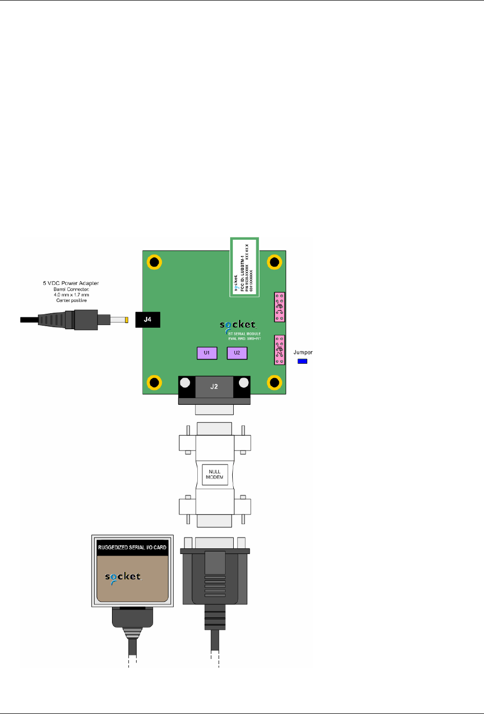
f) Assemble KwikBlue Development Board components:
Figure 7: HCI Test - KwikBlue Development Board Set-up
April 23, 2004 Copyright © 2003-2004 Socket Communications, Inc. Page 13
Document#: 6410-00215-C CONFIDENTIAL Revision 1.04

KwikBlue Module Development Kit Installation Guide
g) Insert jumper on JP2; default configuration is pins 1 to 2 for the KwikBlue Module. See Chapter
11, KwikBlue Development Board Jumpers for all jumper configurations.
h) Connect the null modem adapter to KwikBlue Dev Board connector J2.
i) Connect the CF Ruggedized Serial I/O (CF RIO) Card to the null modem adapter.
j) Connect the 5 VDC power supply to KwikBlue Dev Board connector J4.
k) You should see the Bluetooth stack load. A Bluetooth icon will appear in the task bar tray on your
screen. At this point, you can configure the Bluetooth UI options. You can then copy over and run
some of the Bluetooth sample applications from the Bluetooth_Stack_Dev_Tools_CR4.3.38 CD
such as BlueRfcDemo.exe, etc. Refer to the “C:\Drakar Stack Dev Files\Demos” folder. There is
also a small sample source program in the KwikBlue Dev Kit 008D CD “Utilies\PrintDemo”
folder. This program has a Print File menu selection that can be used to send a file.
7.2. Test 2 - KwikBlue Module (or Dev Board) Hard-Wired to Serial Port
The Bluetooth drivers are run on a Windows CE device. If you wish to embed the KwikBlue Module
with its default settings (HCI mode, drivers running on a Windows CE device), the standard speed is
115200 bps. To use the high-speed driver (921600 bps), you must have a high-speed UART that
supports this speed and the baud rate of the module must be re-programmed.
To program the module parameters, follow the software install instructions in the "Desktop Test Set-
up" section. Follow the steps in Chapter 5.1, Module Baud Rate Configuration. Communication
between the module and Bluetooth drivers is through the Serial driver on the COM port the module is
connected to.
a) Follow Steps 1 and 2 as outlined in Test 1 - Devices with Compact Flash or PC Card Slots to
install the Bluetooth drivers.
b) Modify the following registries to configure the Bluetooth drivers for use with the module:
i) Identify the Serial port the module is connected to. As an example, if the module is connected
to HKLM\BuiltIn\Serial2, the registry entry would be:
HKEY_LOCAL_MACHINE\SOFTWARE\Socket Communications\Bluetooth\BT
Device\ComKey="Drivers\BuiltIn\Serial2"
ii) Specify the baud for communication between the module and Bluetooth drivers, i.e,
HKEY_LOCAL_MACHINE\SOFTWARE\Socket Communications\Bluetooth\BT
Device\config="921600 8 E 1 1 1 0"
HKEY_LOCAL_MACHINE\SOFTWARE\Socket Communications\Bluetooth\BT
Device\config="115200 8 E 1 1 1 0"
April 23, 2004 Copyright © 2003-2004 Socket Communications, Inc. Page 14
Document#: 6410-00215-C CONFIDENTIAL Revision 1.04

KwikBlue Module Development Kit Installation Guide
c) There is a program on the KwikBlue Dev Kit 008D CD that can be used to open a COM port on
your device and verify the module is connected correctly. The program is called PrintDemo.exe
and is under the “\Utilities\Print Demo” folder.
i) The KwikBlue Module sends out a repeating sequence of connection bytes “C0 00 41 00 BE
DA DC ED ED C0” every 250 ms. These bytes indicate to the Bluetooth drivers running on
the WinCE device that the module is ready to be used. When the COM port that the module is
connected to is opened, the bytes can be displayed. This indicates that the module is
connected correctly and ready to be used by the Bluetooth drivers. The baud rate for opening
the port is specified in Port.c and must be set:
PortDCB.BaudRate = 921600;
PortDCB.BaudRate = 115200; (default module baud)
ii) The PrintDemo.exe has a menu selection called 'Load Stack'. This is a one line
ActivateDevice() call to the registry to which loads the stack. The code is provided below for
reference. The ActivateDevice() call loads BCSPStack.dll.
HANDLE g_hBCSP;
case IDC_LOAD_BCSP:
g_hBCSP = ActivateDevice (TEXT("SOFTWARE\\Socket
Communications\\Bluetooth\\Bt Device"), 0);
if(g_hBCSP == NULL)
{ MessageBox(hDlg, TEXT("ActivateDevice (BCSP) Failed"), TEXT("Error
BCSP Load"), MB_OK);
}
break;
d) BCSPStack.dll in turn loads BtDevMan.exe. BtDevMan.exe appears as a Bluetooth icon running
in the screen tray task bar.
e) Virtual COM Port configurations: BtDevMan.exe loads BTVCOMM.dll. All Bluetooth COM
ports that are used by the stack come from BTVCOMM.dll. Bluetooth needs at least one default
COM port to function. For industrial type applications where the remote device being connected
to expects to be a printer or GPS device, the default COM port is usually configured to be the
"Bluetooth COM Port" (Serial Profile). For more commercial applications where the remote
device is expected to be a phone, the default COM port is configured to be the "Bluetooth Phone
Port" (this is the standard retail release configuration). The following registries enable a Virtual
COM port for use.
f) HKEY_LOCAL_MACHINE\SOFTWARE\Socket Communications\BtDevMan\1.0
[TYPE_DWORD] COMEnabled=1 (Bluetooth COM Port (Serial Profile))
[TYPE_DWORD] FaxEnabled=0
[TYPE_DWORD] DesktopEnabled=0
[TYPE_DWORD] LapEnabled=0
[TYPE_DWORD] PrinterEnabled=0
[TYPE_DWORD] PhoneEnabled=0
April 23, 2004 Copyright © 2003-2004 Socket Communications, Inc. Page 15
Document#: 6410-00215-C CONFIDENTIAL Revision 1.04

KwikBlue Module Development Kit Installation Guide
g) HKEY_LOCAL_MACHINE\SOFTWARE\Socket
Communications\Bluetooth\BtDevMan\1.0\BuiltInPort
BuiltInPort (DWORD) displays the check-box that appears on the COM Ports tab in the UI. It has
one of the following values:
0 = Phone (Enabled by default if BuiltInPort key is not present)
1 = Lap
2 = Desktop
3 = Printer
4 = Fax
5 = Bt COM Port
(BTVCOMM.dll could also be loaded by an ActivateDevice() call).
BtDevWin.exe launches the Device Discovery window. This is also launched by selecting
Advanced Features, Bluetooth Devices from the tray icon menu.
h) After completing the ActivateDevice() on BCSPStack.dll, the Bluetooth stack should load. A
Bluetooth icon will appear in the task bar tray on your screen; at this point, the Bluetooth UI
options can be configured. Bluetooth sample applications, such as BlueRfcDemo.exec, can be
copied over and run from the KwikBlue Dev Kit 008D CD “\Drakar Stack Dev Files\Demos”
folder. The PrintDemo sample source program in the KwikBlue Dev Kit 008D CD
“\Utilities\PrintDemo” folder contains a Print File menu selection that can be used to send a file.
April 23, 2004 Copyright © 2003-2004 Socket Communications, Inc. Page 16
Document#: 6410-00215-C CONFIDENTIAL Revision 1.04

KwikBlue Module Development Kit Installation Guide
8. Suspend\Resume
Keeping the Bluetooth hardware active during a suspend still has some issues which is why the module
should be powered down during a suspend:
1) On Suspend, the KwikBlue Module should be powered down. The mechanism for power-down is
customer implementation dependent.
2) On Resume, the KwikBlue Module should be powered back up. The mechanism for power-up is
customer implementation dependent. On power-up, the KwikBlue module running at 921 Kbps
requires approximately 800 ms to become connectable.
3) On Resume, BCSPStack.dll must be shutdown. A DeActivateDevice() call must be made on
‘HKLM\Software\Socket Communications\Bluetooth\Bt Device\’ with the handle obtained earlier
from the ActivateDevice() call. This will cause BCSPStack.dll to shutdown the rest of the stack
(\Windows\BtDevMan.exe).
4) The stack must then be loaded with an ActivateDevice() call on ‘HKLM\Software\Socket
Communications\Bluetooth\Bt Device\’.
9. Bluetooth Driver List
The following binaries comprise the Bluetooth drivers for the module case. They are placed in the
\Windows directory of the device.
BlueSocket.dll
BtDevMan.exe
BtDevWin.exe
BTExchange.dll
Btvcomm.dll
ToothSocket.dll
ConnectWiz.exe
Drakar.dll
DkUiUtils.dll
BCSPStack.dll (used by embedded modules and Rev G (and higher) CF Cards With
Bluetooth Wireless Technology)
ScktIrda.cpl (IrDa Control Panel configuration utility - optional)
Binaries that occur in the retail release but are not included in a module build:
WendyStack.dll (only used by older Rev F CF Cards With Bluetooth Wireless Technology -
not in production any more)
SDBTASckt.dll (SDIO driver - SDIO slot devices only)
SIO_BT.DLL (high speed serial driver - Rev G and above cards only)
BtCustomSetup.dll (set-up wizard for *.cab install, not part of stack)
April 23, 2004 Copyright © 2003-2004 Socket Communications, Inc. Page 17
Document#: 6410-00215-C CONFIDENTIAL Revision 1.04

KwikBlue Module Development Kit Installation Guide
10. Certification Testing Utilities
The CSR software provides some utilities such as BlueTest.exe (see Desktop Test Set-up) which can be
used in certification testing. At the time of this release, there are not CSR utilities that can be run under
Windows CE, CE .NET or Windows Mobile for certification testing. Check the CSR website for the latest
information http://www.csr.com/home.htm.
If it is desired to use BlueTest.exe on the desktop, a WinCE utility is needed to pass data between
BlueTest.exe and the module. When running this WinCE utility, the Bluetooth drivers must be disabled so
the utility can communicate directly with the KwikBlue Module. The utility opens two COM ports; the
first COM port is to the module, the second COM port is to the incoming connection from BlueTest.exe
on the desktop side. Once this bi-directional communication has been established, BlueTest.exe can be
used for certification testing.
11. KwikBlue Development Board Jumpers
JP2 Description
Pin 1 to 2 Install only for BC02 module
Pin 3 to 4 Install only for BC01 module
Pin 5 to 6 Install to light LED when power is on
Pin 6 to 8 Install to connect LED to PIO_1
Pin 7 to 8 Install to connect RS232 signal RI to PIO_1
Pin 9 to 10 Install to connect INVALID# RS232 to PIO_1
Factory default jumpers
Table 3: KwikBlue Development Board Jumpers
April 23, 2004 Copyright © 2003-2004 Socket Communications, Inc. Page 18
Document#: 6410-00215-C CONFIDENTIAL Revision 1.04
KwikBlue Module Development Kit Installation Guide
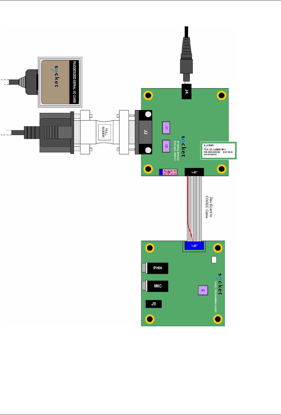
12. Audio CODEC Setup (Optional)
Figure 8: Optional Audio CODEC Board Setup
Setting up the CODEC board:
Using 10-pin ribbon cable, connect CODEC JP1 to KwikBlue Development Board connector
JP1.
Connect headphone/microphone to CODEC connector J9.
Connect 5 VDC power supply to KwikBlue development board connector J4
April 23, 2004 Copyright © 2003-2004 Socket Communications, Inc. Page 19
Document#: 6410-00215-C CONFIDENTIAL Revision 1.04

KwikBlue Module Development Kit Installation Guide
13. KwikBlue Development Board Bill of Materials (BOM)
(refer to the schematic “0200-00120-03.pdf” on the KwikBlue Dev Kit 008D CD)
Qty Reference Description Mfr Part Number
4 C1, C2, C3, C4 CAP, 0.1UF, 16V, Y5V, +80/-20%, CERAMIC Panasonic ECJ-0EF1C104Z
1 C11 CAP, 1UF, 16V, TE, 20%, TANTALUM Panasonic ECS-T1CY105R
1 C12 CAP, 4.7UF, 16V, 20%, TANTALUM Panasonic ECS-T1CY475R
1 C13 CAP, 0.1UF, 10V, 10%, CERAMIC Panasonic ECJ-0EB1A104K
1 C14 CAP, 470PF, 50V, 10%, CERAMIC Panasonic ECJ-0EB1H471K
1 C15 CAP, 0.1UF, 10V, 10%, CERAMIC Panasonic ECJ-0EB1A104K
2 C16, C17 CAP, 0.01UF, 16V, X7R, 10%, CERAMIC Panasonic ECJ-0EB1C103K
1 C8 CAP, 4.7UF, 16V, 20%, TANTALUM Panasonic ECS-T1CY475R
1 CR2 DIO, MA8068, 6.8V, 150MW, ZENER Panasonic MA8068
2 CR3, CR1 DIO, BAT54C, 30V, 200MA, SILICON
SCHOTTKY BARRIER Diodes BAT54C
1 CR4 DIO, MA8056, 5.6V, 150MW, ZENER Panasonic MA8056
1 CR5 LED, LED-BLUE-CLEAR, 3.7V, 20MA,
CLEAR Liteon LTST-C191CBKT
1 J1 CON, CON20-SMT, VERT, FEM, SKT,
GOLD PLATED Matsushi AXK5F20545J
1 J2 CON, DB9-M-RT, METAL HOUSING AMP 747840-4
1 J4 CON, PJACK-1.65MM-RT, PLASTIC
HOUSING CUI PJ-016
2 JP2, JP1 HDR, HDR10-DIP, VERT, STAMPED PIN
GOLD Samtec TSW-105-07-S-D
1 Q1 REG, MIC5205-3.3BM5, 3.3V, 1% Micrel MIC5205-3.3BM5
2 R2, R3 RES, 2.7K, 200V, 1/8W, 5%, THICK FILM Panasonic ERJ-6GEYJ272V
2 R4, R5 RES, 330K, 50V, 1/16W, 5%, THICK FILM Panasonic ERJ-2GEJ334X
1 R6 RES, 100K, 100V, 1/16W, 5%, THICK FILM Panasonic ERJ-2GEJ104
1 R7 RES, 470K, 100V, 1/16W, 5%, THICK FILM Panasonic ERJ-2GEJ470
1 R8 RES, 560, 50V, 1/16W, 5%, THICK FILM Panasonic ERJ-2GEJ561
1 U1 ANA, MAX3243 Maxim MAX3243CAI
1 U2 ANA, PI5A100, 2V/6V Pericom PI5A100W
2 U7, U6 LOG, SN74LVCG17, 1.65V-5.5V TI SN74LVC1G17DCKR
4 HDW- 4-40
HEXNUT HDW, HEXNUT-4-40, 4-40 BF H216
4 HDW- M/F 4-
40 HEX
STANDOFFS
HDW, SPACER-HEX-M-F, 4-40, 0.500,
ALUMINUM Keystone 8401
Table 4: KwikBlue Development Board Bill of Materials
April 23, 2004 Copyright © 2003-2004 Socket Communications, Inc. Page 20
Document#: 6410-00215-C CONFIDENTIAL Revision 1.04

KwikBlue Module Development Kit Installation Guide
14. CODEC Board Bill of Materials (BOM)
(refer to the schematic “0200-00133-01.pdf” on the KwikBlue Dev Kit 008D CD)
Qty Reference Description Mfr Part Number
1 C12 CAP, 68UF, 10V, TC, 10%, CERAMIC Matsuo 267E1002686K-720
1 C13 CAP, 0.01UF, 50V, Y5V, +80/-20, CERAMIC Samsung CL10F103ZBNC
2 C14, C23 CAP, 470PF, 50V, X7R, 10%, CERAMIC Panasonic ECU-V1H471KBV
1 C15 CAP, 10UF, 10V, Y5V, +80/-20, CERAMIC Murata GRM230Y5V106Z010AL
4 C16, C17,
C22, C25 CAP, 0.1UF, 25V, Y5V, +80/-20%, CERAMIC Panasonic ECJ-1VF1H104Z
4 C18, C19,
C20, C21 CAP, 1000PF, 25V, X7R, 10%, CERAMIC AVX 06033C102KATRA
2 J7, J6 CON, PHNO-ST-3.5MM, RT, PLASTIC
HOUSING SWTCRAFT 35RAPC4BV4
1 J9 CON, PHNO-ST-2.5MM, PLASTIC
HOUSING DGS 2502
1 JP1 HDR, HDR10-DIP, VERT, STAMPED PIN
GOLD Samtec TSW-105-07-S-D
1 L3 IND, 5.6UH, 120MA, 5% Panasonic ELJ-FC5R6JF
1 POT1 POT, 50K, 300VDC, 1/4W, 10% Bourns 3214W-1-503E
4 R44, R45,
R49, R52 RES, 1K, 50V, 1/16W, 5%, THICK FILM Panasonic ERJ-3GSYJ1.0K
6 R46, R50,
R54, R58,
R70, R72
RES, 0.0, 100V, 1/16W, 5%, THICK FILM Panasonic ERJ-3GSYJ0.0
2 R47, R53 RES, 75K, 50V, 1/16W, 5%, THICK FILM Panasonic ERJ-3GSYJ753
1 R48 RES, 20K, 50V, 1/10W, 5%, THICK FILM Panasonic ERJ-3GEYJ20K
2 R71, R64 RES, 100K, 50V, 1/16W, 5%, THICK FILM Panasonic ERJ-3GSYJ100K
2 TP3, TP4 HDR, HDR1-SIP, VERT, STAMPED PIN
GOLD Sullins PZC01SAAN
1 U4 PER, MC145483, 3V Motorola MC145483SD
1 HDW-
RIBBON
CABLE
HDW, 10PIN-CBL, 6" AMP A3AAG-1006G
4 HDW- 4-40
HEXNUT HDW, HEXNUT-4-40, 4-40 BF H216
4 HDW- M/F 4-
40 HEX
STANDOFFS
HDW, SPACER-HEX-M-F, 4-40, 0.500,
ALUMINUM Keystone 8401
Table 5: CODEC Board Bill of Materials
April 23, 2004 Copyright © 2003-2004 Socket Communications, Inc. Page 21
Document#: 6410-00215-C CONFIDENTIAL Revision 1.04

KwikBlue Module Development Kit Installation Guide
15. Errata
Pins 1 and 3 on the CODEC board were reversed so the CODEC-to-dev-kit cable has corrected this
condition. The next revision of the board and cable will reflect the proper board layout.
April 23, 2004 Copyright © 2003-2004 Socket Communications, Inc. Page 22
Document#: 6410-00215-C CONFIDENTIAL Revision 1.04

KwikBlue Module Development Kit Installation Guide
16. Appendix A: BC01 vs. BC02 Pin Assignments
BC01 vs. BC02 Pin Assignments
BC01 – Class 1 BC02 – Class 2 BC02 – Class 1 Changed
between
Class 1 & 2
Pin #
GROUND GROUND GROUND 1
PCM_OUT PCM_OUT PCM_OUT 2
PCM_IN PCM_IN PCM_IN 3
PCM_PWR_DWN PIO_1 PIO_5 YES 4
VBUS_IN PIO_4 PIO_4 5
UART_RXD UART_RXD UART_RXD 6
UART_TXD UART_TXD UART_TXD 7
RESET RESET RESET 8
USB_WAKE PIO_3 PIO_3 9
VCC SPI_CSB SPI_CSB YES 10
GROUND GROUND GROUND 11
UART_RTS UART_RTS UART_RTS 12
USB_DETACH SPI_CLK SPI_CLK YES 13
UART_CTS UART_CTS UART_CTS 14
PCM_SYNC PCM_SYNC PCM_SYNC 15
USB_D+ PIO_2 PIO_2 YES 16
USP_D- SPI_MOSI SPI_MOSI YES 17
PCM_CLK PCM_CLK PCM_CLK 18
NC SPI_MISO SPI_MISO YES 19
VCC_PA VCC_3.3V VCC_3.3V 20
Table 6: BC01 vs. BC02 Pin Assignments
April 23, 2004 Copyright © 2003-2004 Socket Communications, Inc. Page 23
Document#: 6410-00215-C CONFIDENTIAL Revision 1.04

KwikBlue Module Development Kit Installation Guide
BC01 Class 1 Module Pin Assignments
Signal Name Function Direction Pin #
GROUND Ground 1
PCM_OUT PCM data stream output OUT 2
PCM_IN PCM data stream input IN 3
PCM_PWR_DWN PCM power down control output OUT 4
VBUS_IN For self-power mode, sense if VBUS is ON IN 5
UART_RXD UART/RxD from DTE IN 6
UART_TXD UART/TxD to DTE OUT 7
RESET System reset IN 8
USB_WAKE Wake up host when events occur during Suspend/Resume OUT 9
VCC Power supply 10
GROUND Ground 11
UART_RTS UART/Ready to send to DTE OUT 12
USB_DETACH Disconnect D+/D- from host IN 13
UART_CTS UART/Clear to send from DTE IN 14
PCM_SYNC PCM frame sync input/output (8 KHz) OUT 15
USB_D+ Positive USB differential data bus IN/OUT 16
USP_D- Negative USB differential data bus IN/OUT 17
PCM_CLK PCM reference clock input/output (256 KHz) OUT 18
NC For internal test use NC 19
VCC_PA Power supply 20
Table 7: BC01 Class 1 Module Pin Assigments
April 23, 2004 Copyright © 2003-2004 Socket Communications, Inc. Page 24
Document#: 6410-00215-C CONFIDENTIAL Revision 1.04

KwikBlue Module Development Kit Installation Guide
BC02 Class 2 Module Pin Assignments
Signal Name Function Direction Pin #
GROUND Power supply return 1
PCM_OUT Serial data from audio CODEC IN 2
PCM_IN Serial data to audio CODEC OUT 3
PIO_1 Generic I/O local host OUT 4
PIO_4 Generic I/O local host RS232 (DTR) OUT 5
UART_RXD Serial data from local host RS232 (RXD) IN 6
UART_TXD Serial data to local host RS232 (TXD) OUT 7
RESET Reset module when HIGH IN 8
PIO_3 Generic I/O local host RS232 (DSR) IN 9
SPI_CSB SPI chip select IN 10
GROUND Power supply return 11
UART_RTS Local host must not send when HIGH OUT 12
SPI_CLK SPI Clock IN 13
UART_CTS Module must not send when HIGH IN 14
PCM_SYNC Audio CODEC signal OUT 15
PIO_2 Generic I/O local host RS232 (DCD) IN 16
SPI_MOSI SPI master out slave in IN 17
PCM_CLK Audio CODEC signal OUT 18
SPI_MISO SPI master in slave out OUT 19
VCC_3.3V Power supply 20
Table 8: BC02 Class 2 Module Pin Assignments
April 23, 2004 Copyright © 2003-2004 Socket Communications, Inc. Page 25
Document#: 6410-00215-C CONFIDENTIAL Revision 1.04

KwikBlue Module Development Kit Installation Guide
BC02 Class 1 Module Pin Assignments
Signal Name Function Direction Pin #
GROUND Power supply return 1
PCM_OUT Serial data from audio CODEC IN 2
PCM_IN Serial data to audio CODEC OUT 3
PIO_5 Generic I/O local host OUT 4
PIO_4 Generic I/O local host RS232 (DTR) OUT 5
UART_RXD Serial data from local host RS232 (RXD) IN 6
UART_TXD Serial data to local host RS232 (TXD) OUT 7
RESET Reset module when HIGH IN 8
PIO_3 Generic I/O local host RS232 (DSR) IN 9
SPI_CSB SPI chip select IN 10
GROUND Power supply return 11
UART_RTS Local host must not send when HIGH OUT 12
SPI_CLK SPI Clock IN 13
UART_CTS Module must not send when HIGH IN 14
PCM_SYNC Audio CODEC signal OUT 15
PIO_2 Generic I/O local host RS232 (DCD) IN 16
SPI_MOSI SPI master out slave in IN 17
PCM_CLK Audio CODEC signal OUT 18
SPI_MISO SPI master in slave out OUT 19
VCC_3.3V Power supply 20
Table 9: BC02 Class 1 Module Pin Assignments
April 23, 2004 Copyright © 2003-2004 Socket Communications, Inc. Page 26
Document#: 6410-00215-C CONFIDENTIAL Revision 1.04