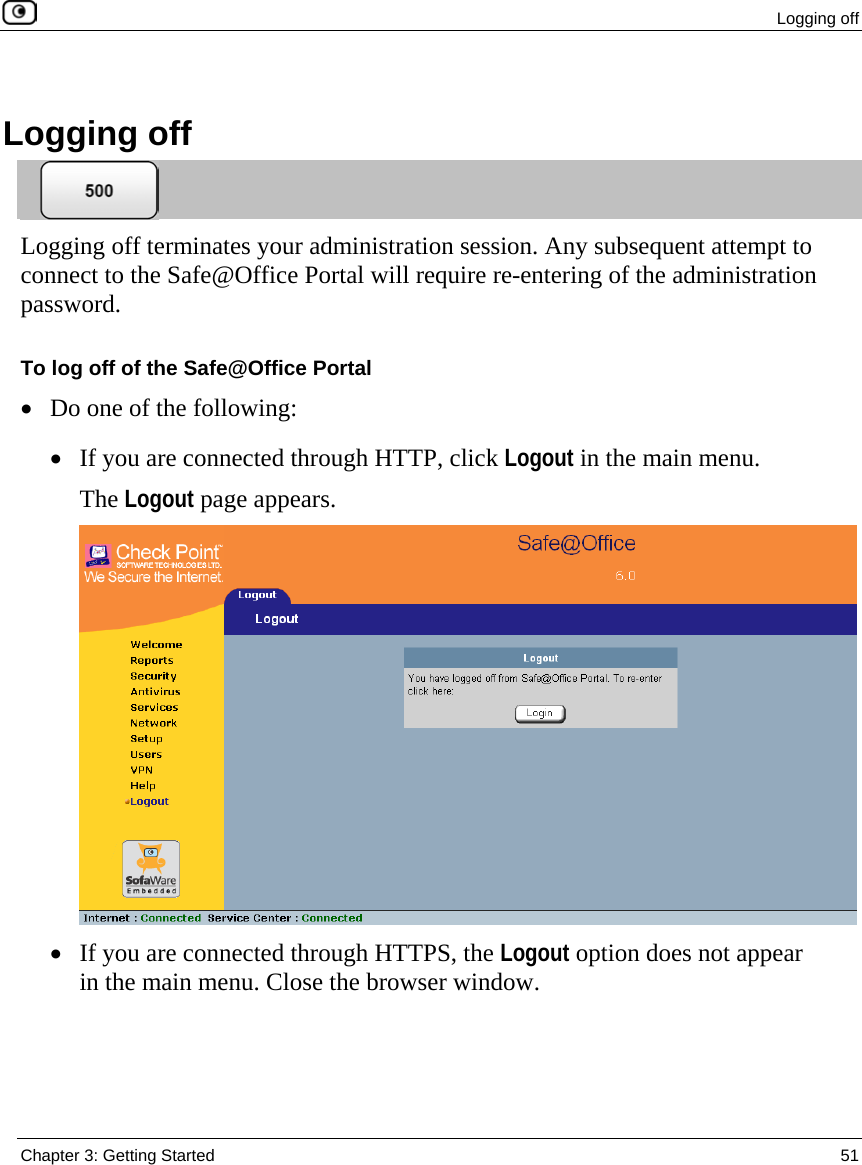
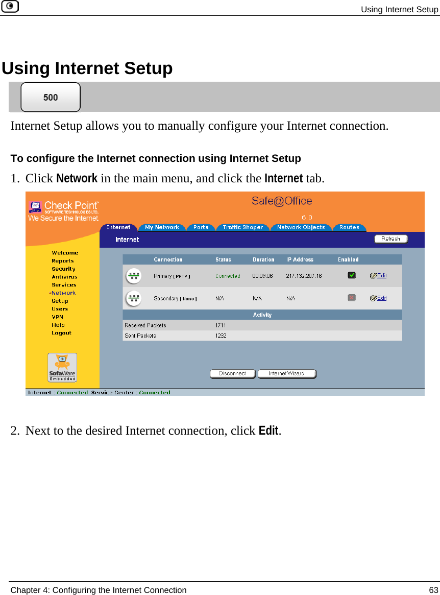
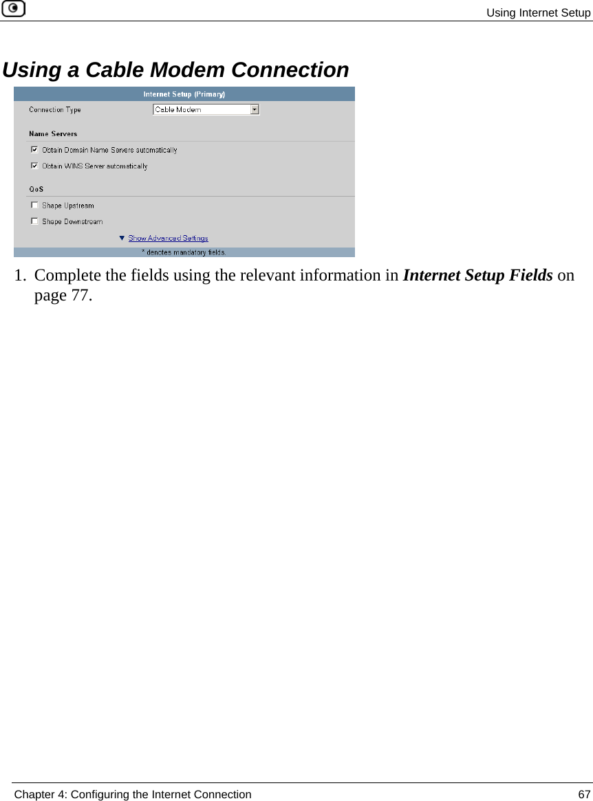
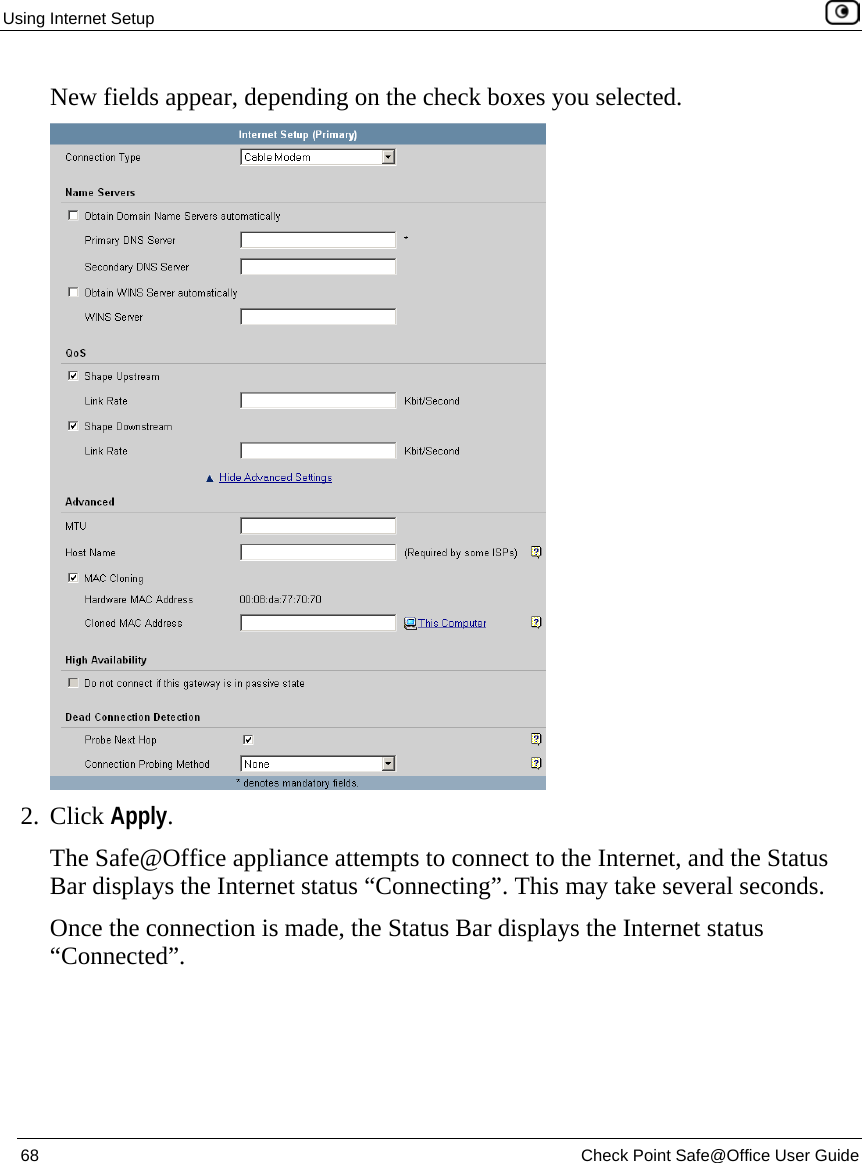
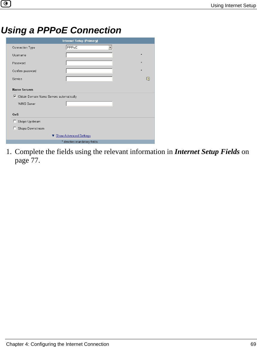
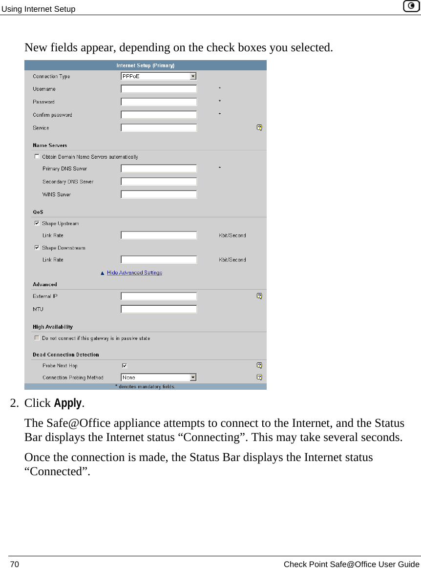
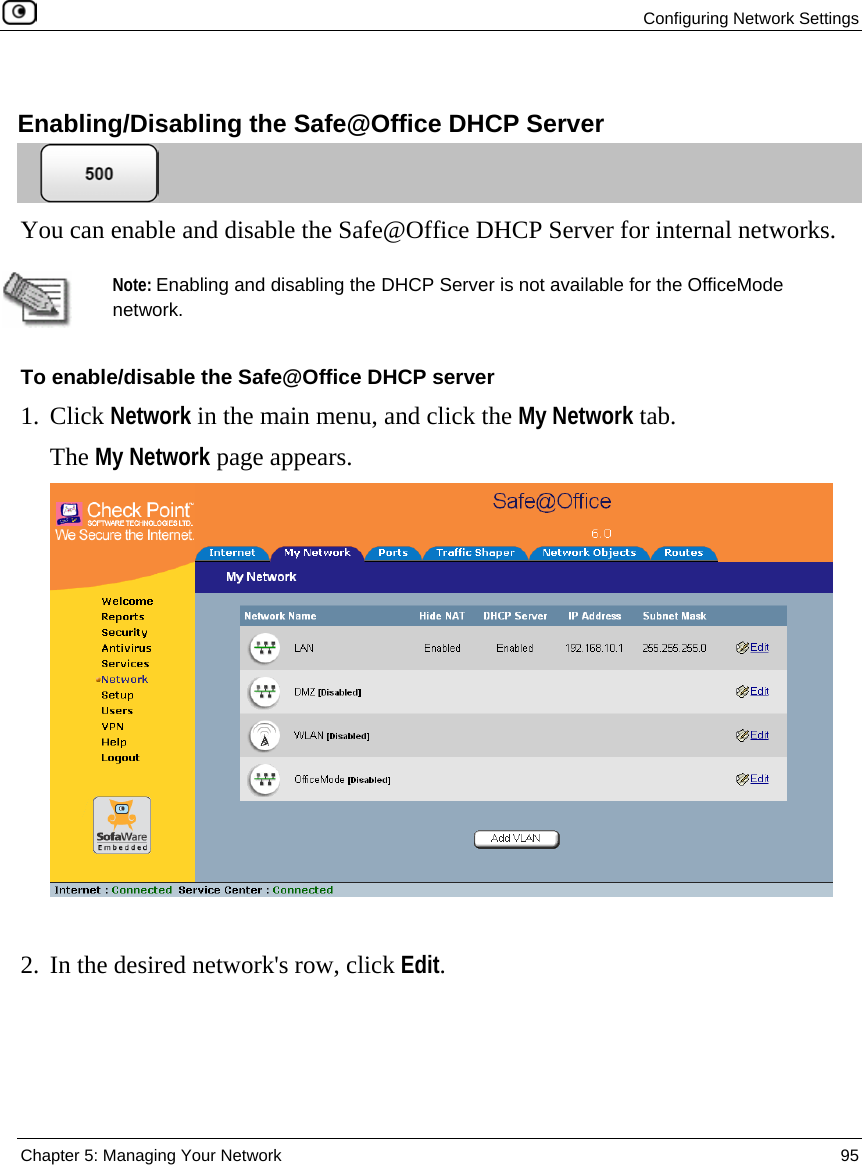
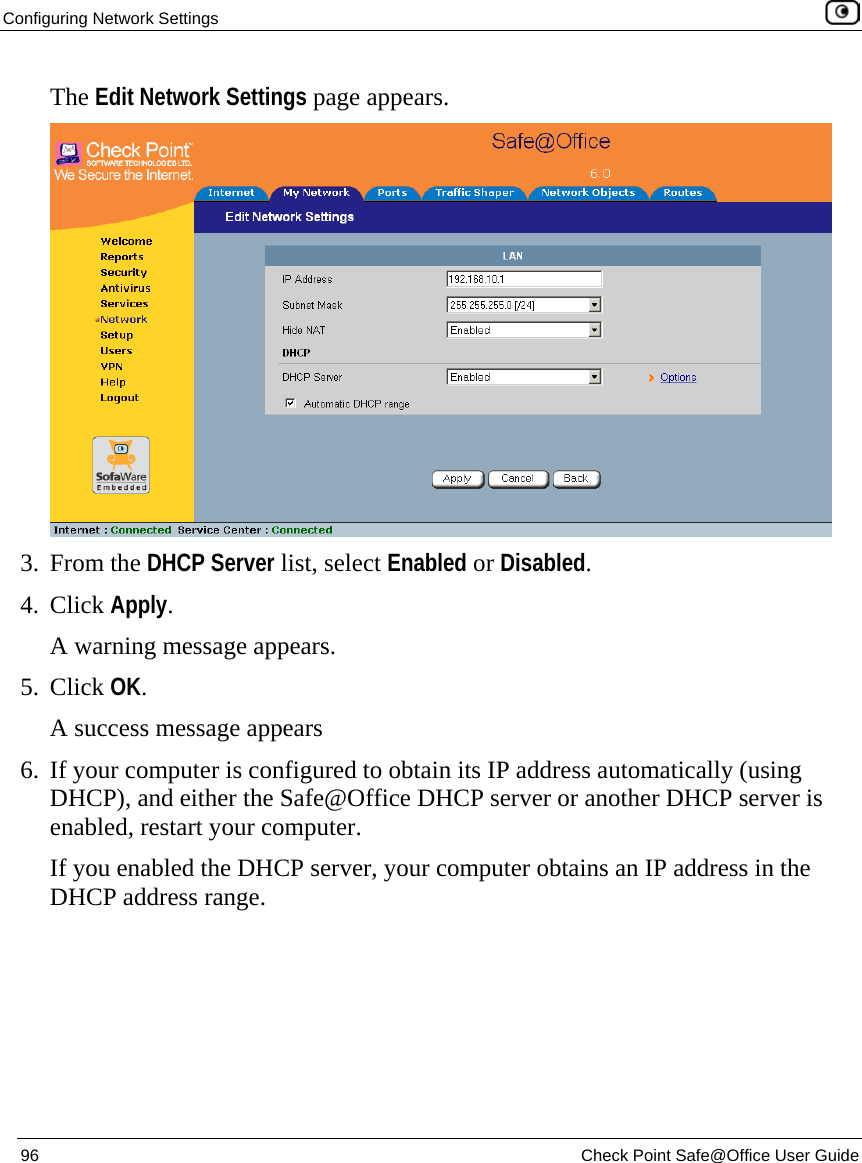
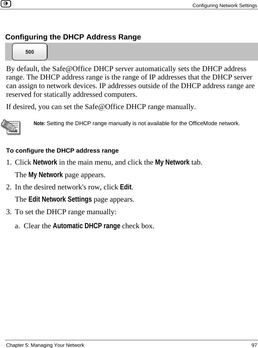
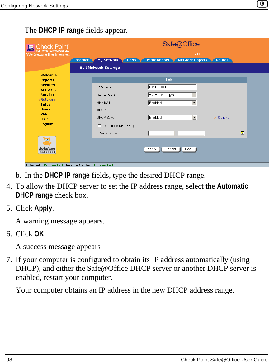
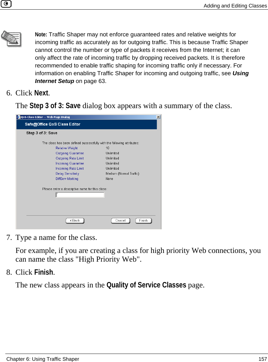
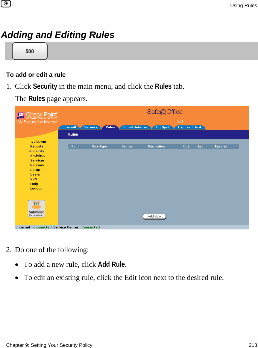
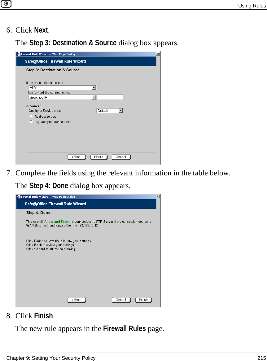
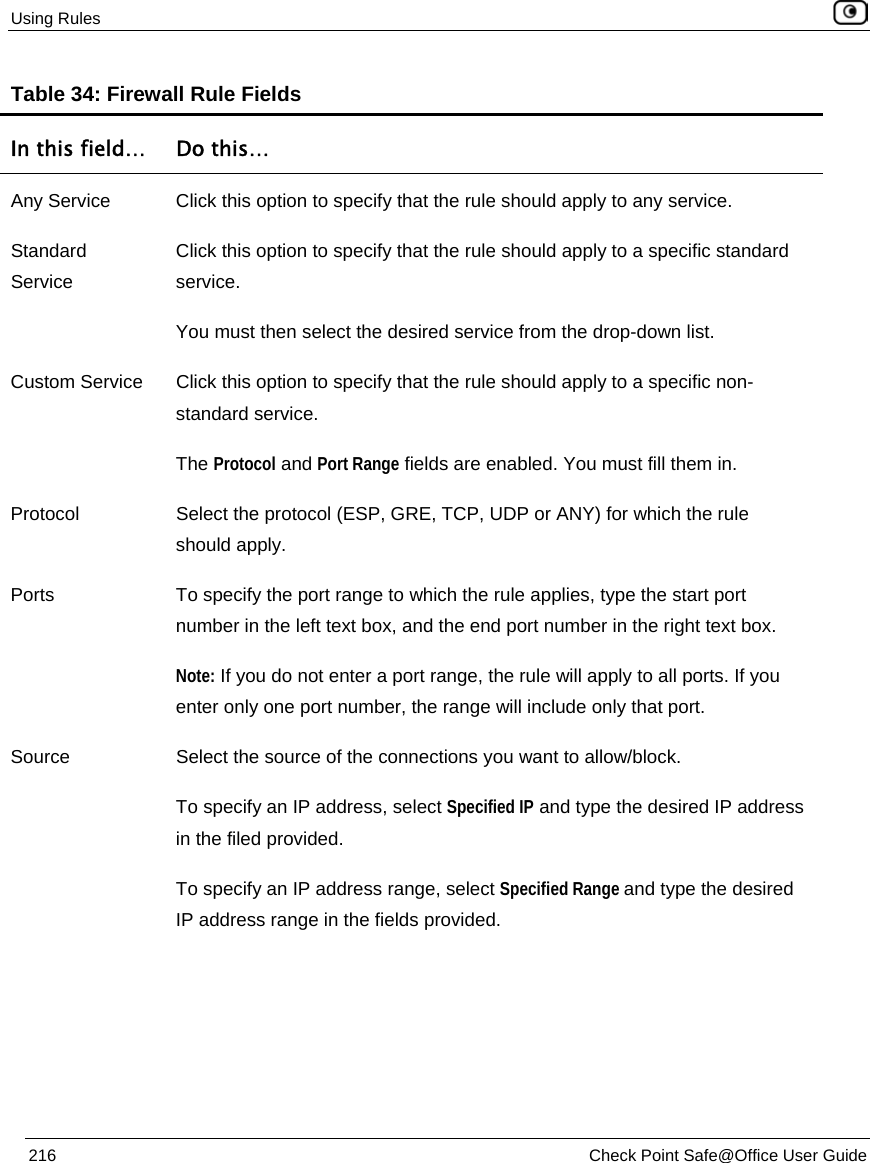
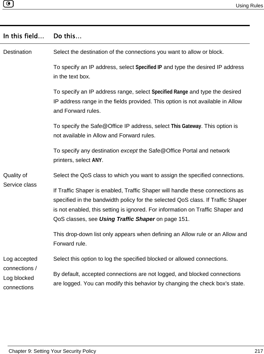
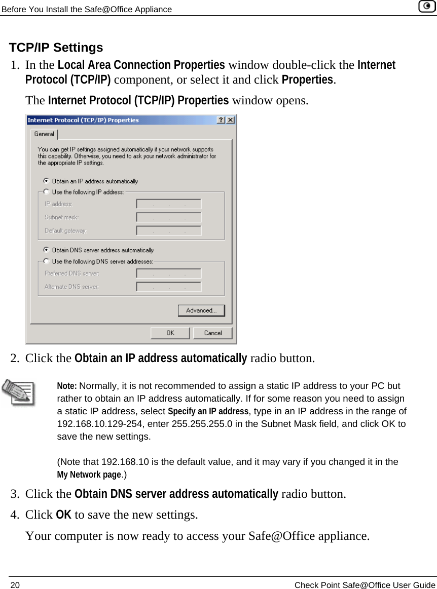
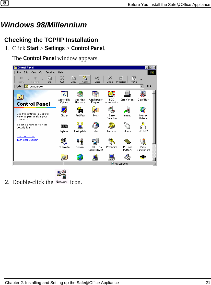
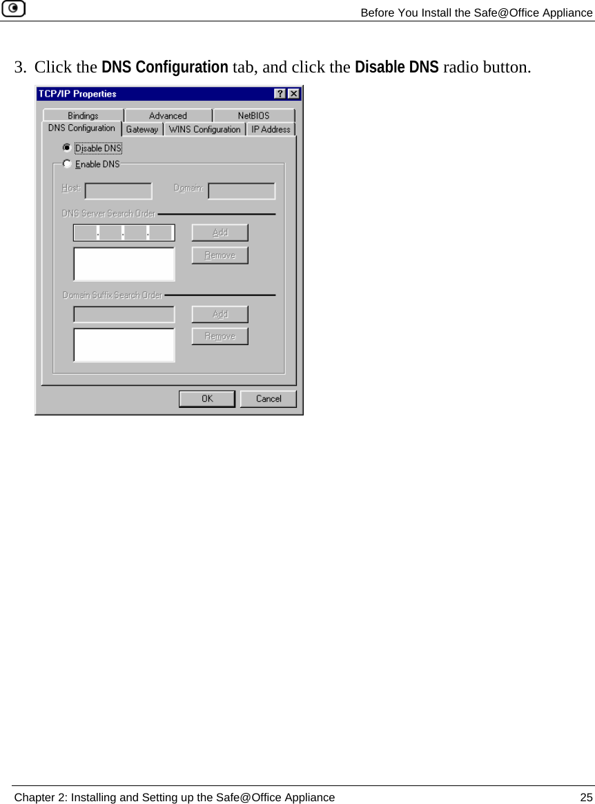
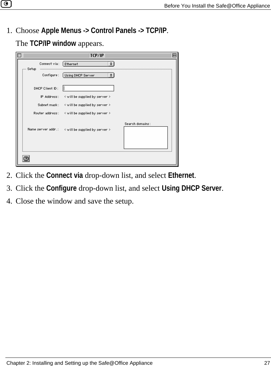
SofaWare Technologies SBXW-166LHGE-6 Wireless Broadband Router User Manual Check Point Safe Office User Guide
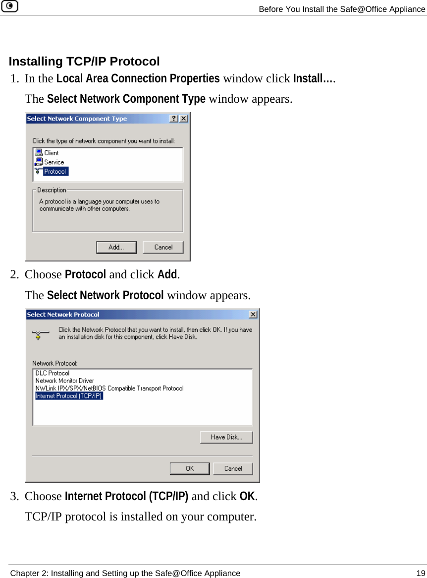
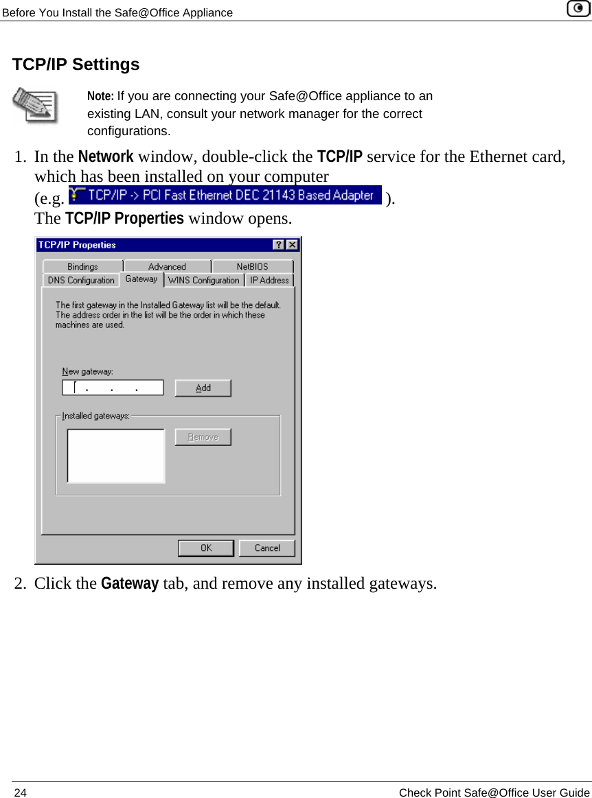
SofaWare Technologies Ltd. Wireless Broadband Router Check Point Safe Office User Guide
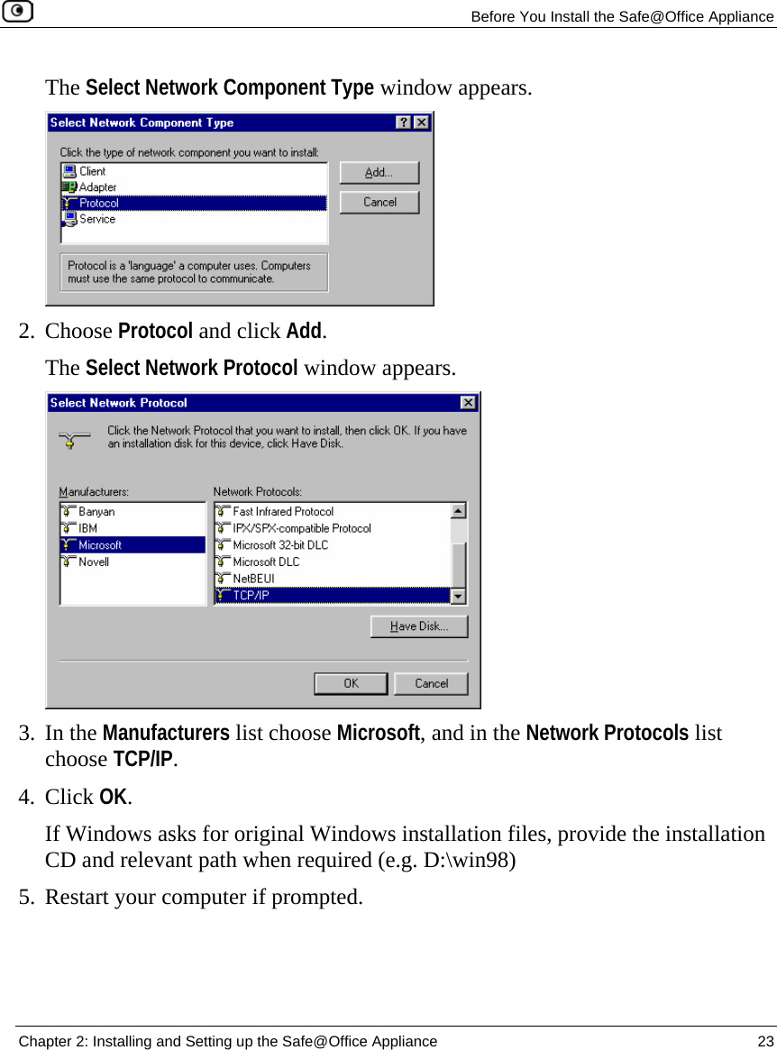
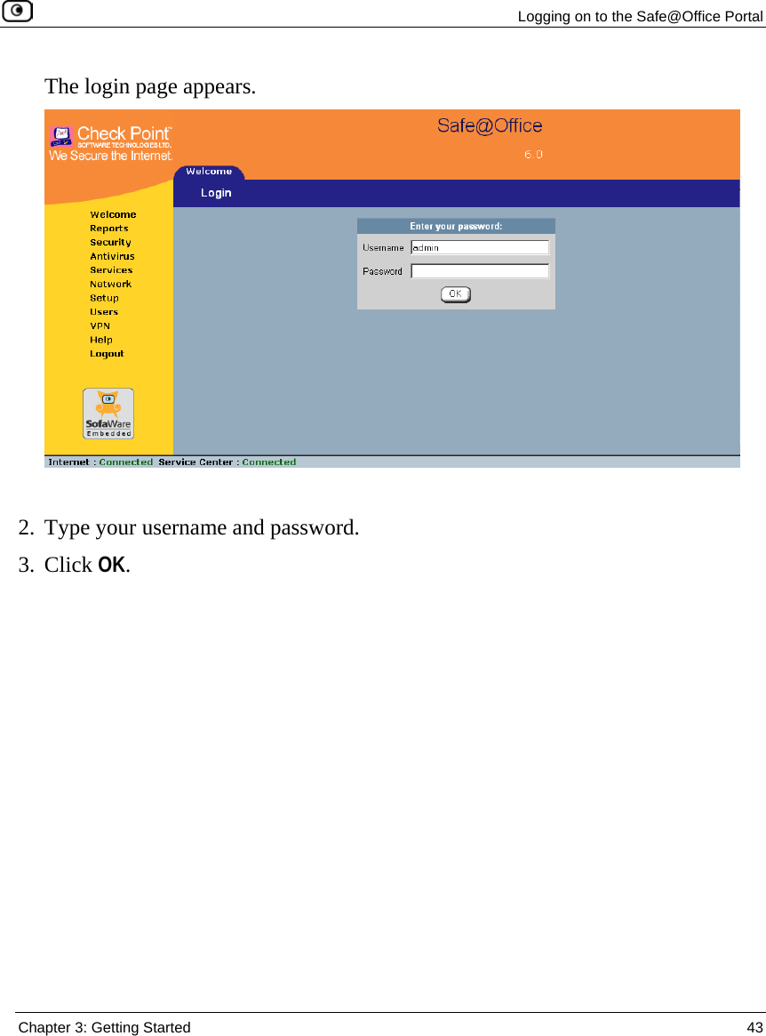
UserManual.wiki
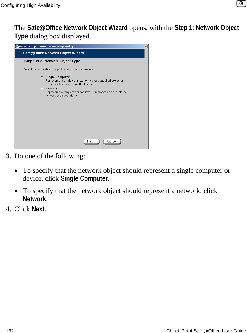
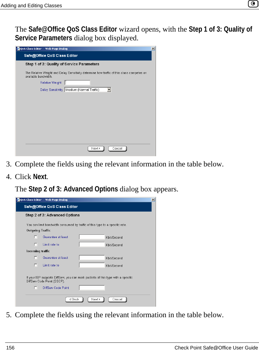
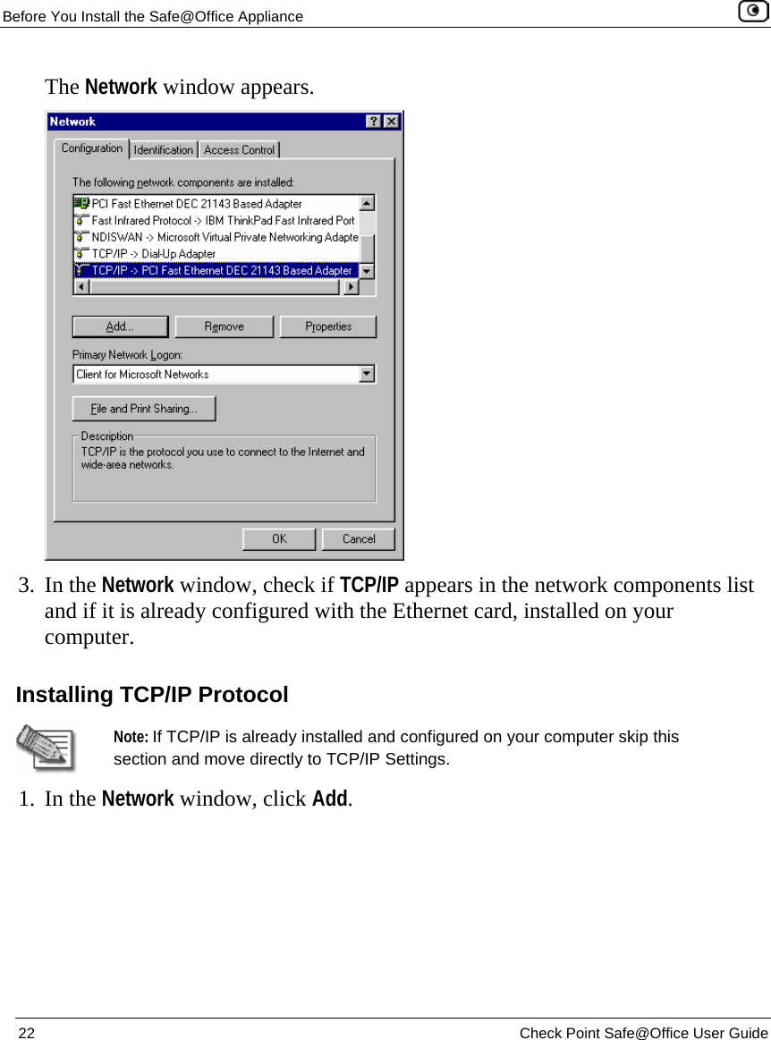
>
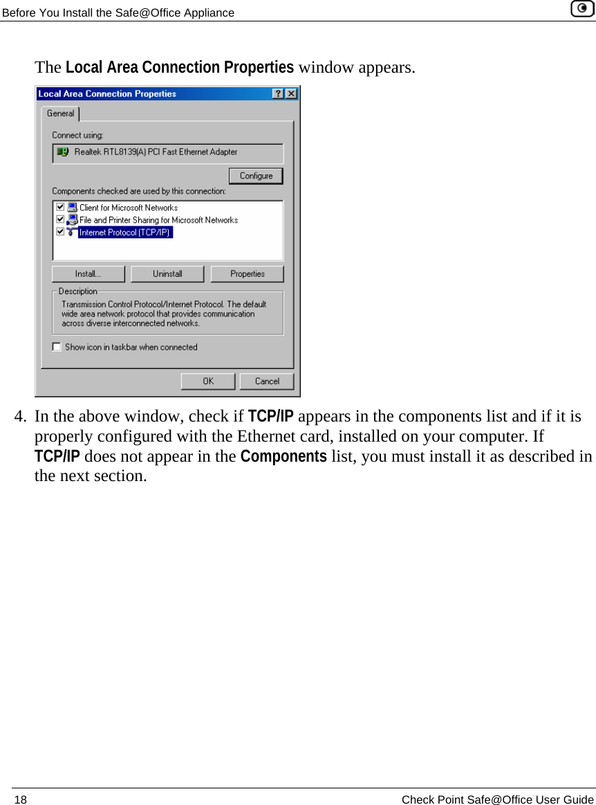
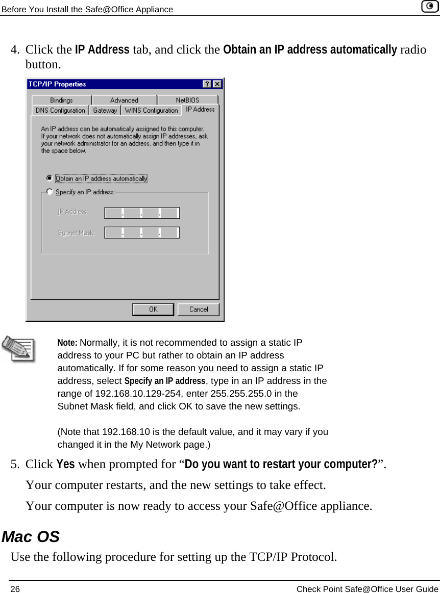
SofaWare Technologies
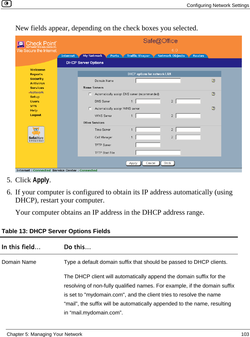
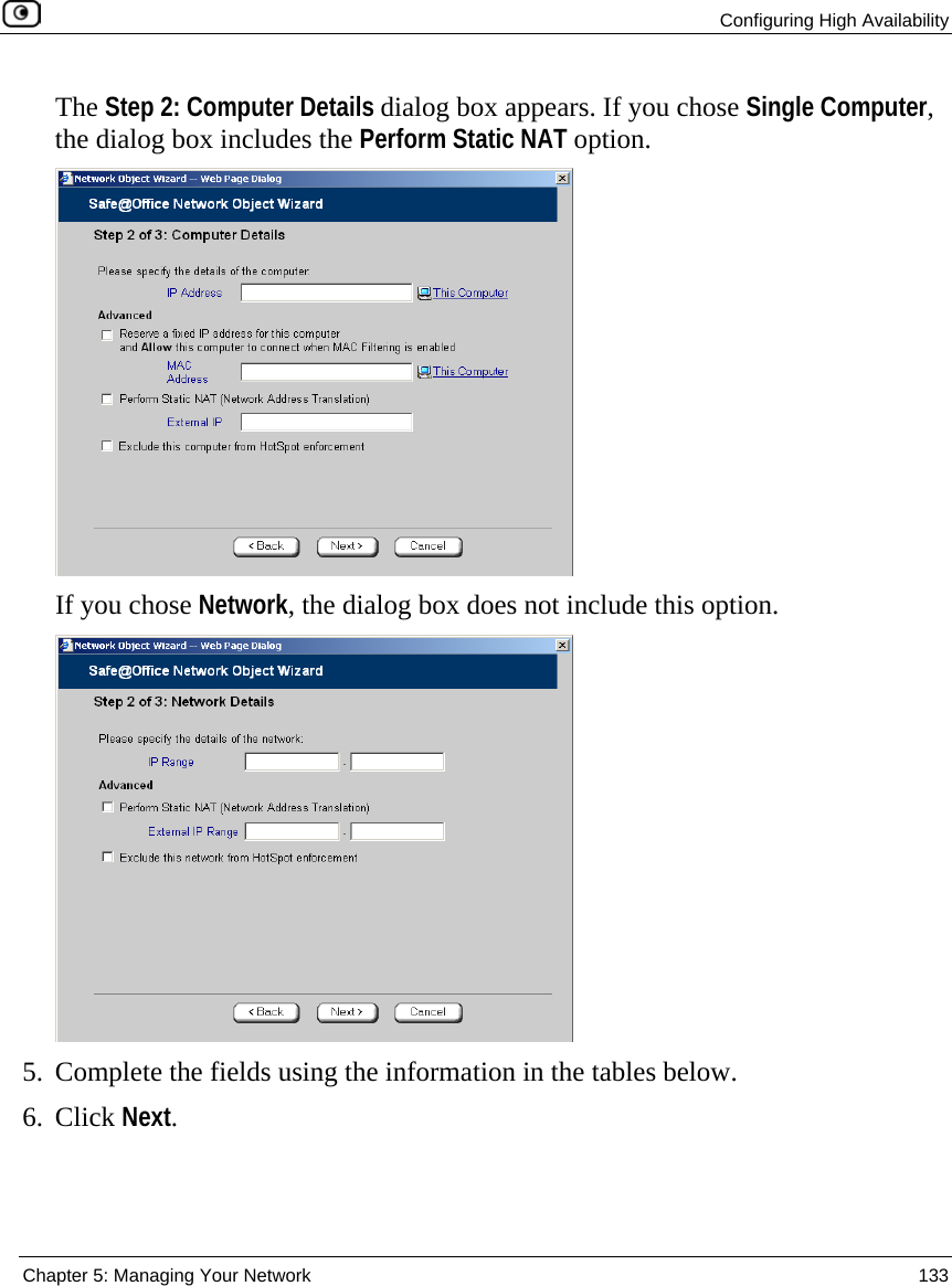
>
SBXW-166LHGE-6 User Manual
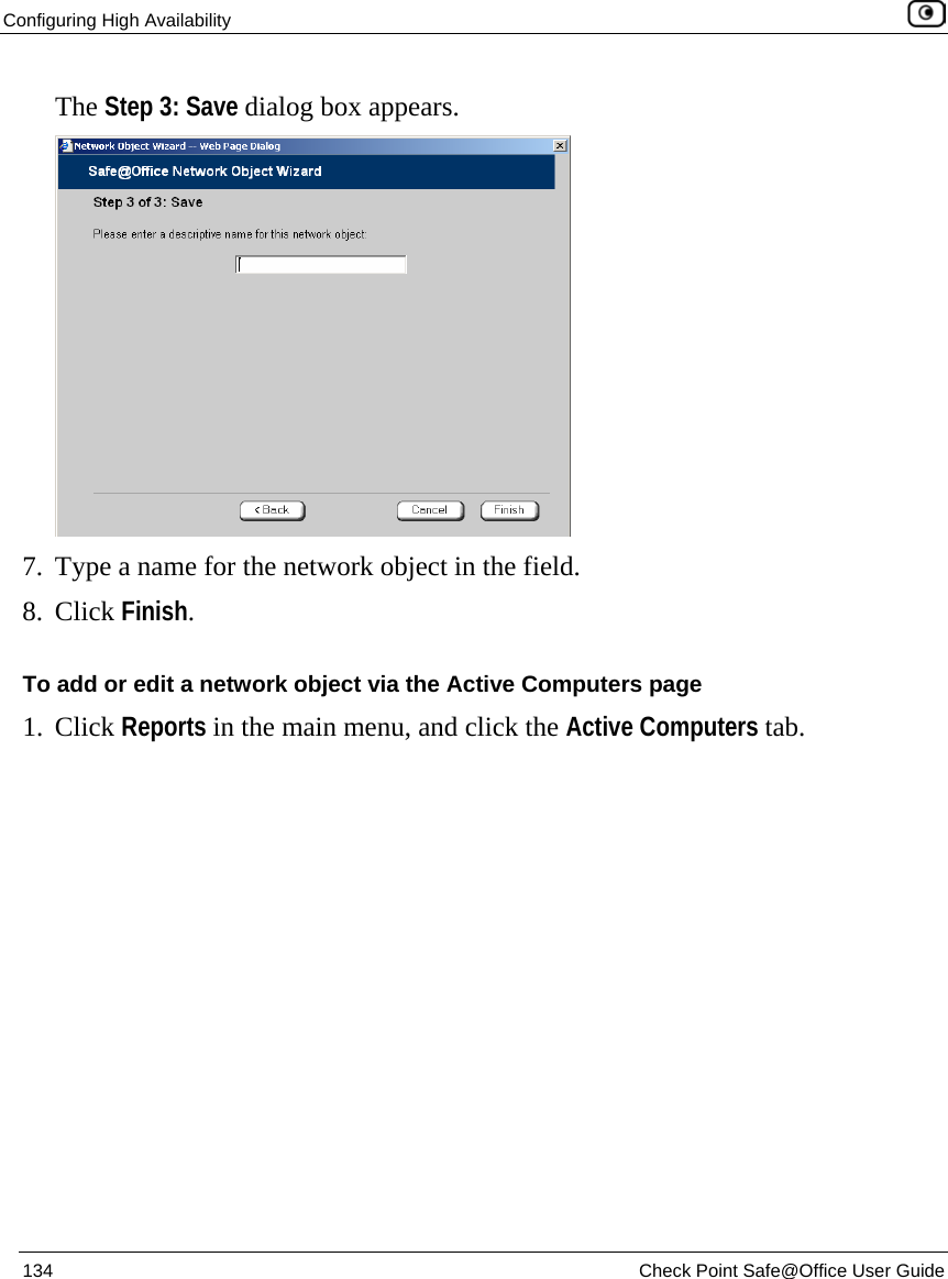
>
Manual Pt1
Contents
1.
Manual Pt1
2.
Manual Pt2
Manual Pt1
Navigation menu
Upload a User Manual
Namespaces
Wiki Guide
HTML
PDF
Info
Views
User Manual
Discussion / Help
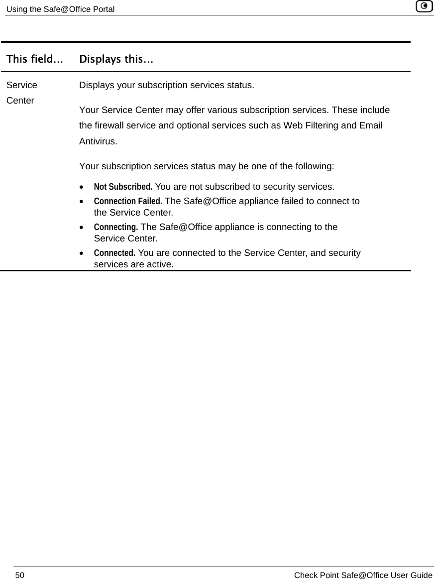
Navigation
![Using the Safe@Office Portal Chapter 3: Getting Started 49 Table 7: Status Bar Fields This field… Displays this… Internet Your Internet connection status. The connection status may be one of the following: • Connected. The Safe@Office appliance is connected to the Internet. • Connected – Probing OK. Connection probing is enabled and has detected that the Internet connectivity is OK. • Connected – Probing Failed. Connection probing is enabled and has detected problems with the Internet connectivity. • Not Connected. The Internet connection is down. • Establishing Connection. The Safe@Office appliance is connecting to the Internet. • Contacting Gateway. The Safe@Office appliance is trying to contact the Internet default gateway. • Disabled. The Internet connection has been manually disabled. Note: You can configure both a primary and a secondary Internet connection. When both connections are configured, the Status bar displays both statuses. For example “Internet [Primary]: Connected”. For information on configuring a secondary Internet connection, see Configuring the Internet Connection on page 53.](https://usermanual.wiki/SofaWare-Technologies/SBXW-166LHGE-6.Manual-Pt1/User-Guide-694885-Page-65.png)