Sokkia Topcon WT11 Bluetooth Module User Manual RC PR3 E
Sokkia Topcon Co., Ltd. Bluetooth Module RC PR3 E
UserManual.wiki
>
Sokkia Topcon
>
WT11 User Manual
User manual
Navigation menu
Upload a User Manual
Namespaces
Wiki Guide
HTML
PDF
Info
Views
User Manual
Discussion / Help
Navigation
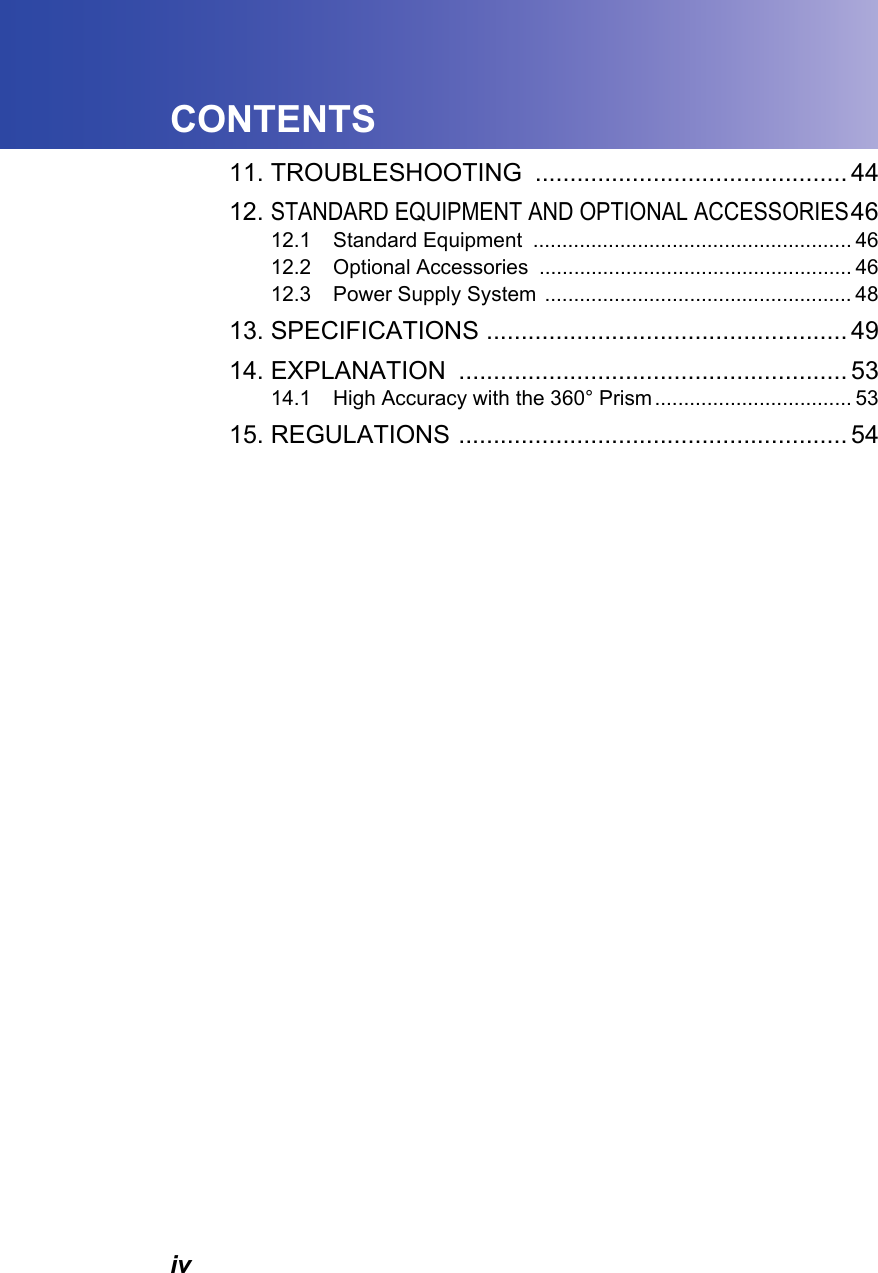
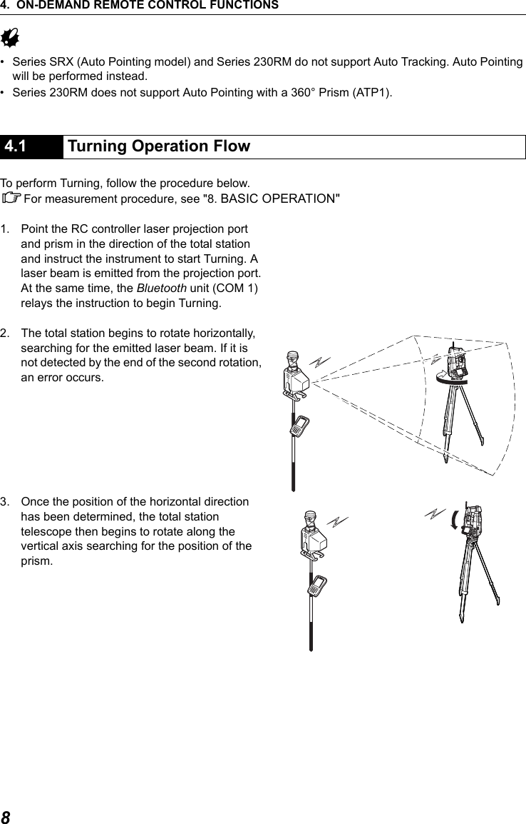
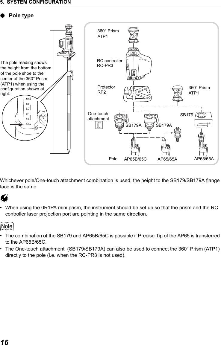
![iiHOW TO READ THIS MANUALSymbolsThe following conventions are used in this manual.G: Indicates precautions and important items which should be read before operations.C: Indicates a cross-reference to refer to for additional information.$: Indicates supplementary explanation.&: Indicates an explanation for a particular term or operation.[DIST] etc. : Indicates softkeys on the total station display.{ESC} etc. : Indicates operation keys on the total station.I POWER etc. : Indicates RC controller LEDs.Screens and illustrations• Except where stated, "SRX" means Series SRX, "NET" means NET05 and NET1, "total station" means "Series SRX/NET05/NET1/Series 230RM", and “RC controller” means the control unit for the On-demand Remote Control System in this manual.• The content of this system manual is mainly concerned with explaining the operation of the RC controller. Appended functions for the SET are described in "7. APPENDED SETTINGS FOR THE SERIES 230RM". For precautions and operating method, please read the Series 230RM Operator’s Manual.• Screens and illustrations used in this manual are of SRX (with RC-TS3 handle) or Series 230RM.](https://usermanual.wiki/Sokkia-Topcon/WT11/User-Guide-863240-Page-4.png)
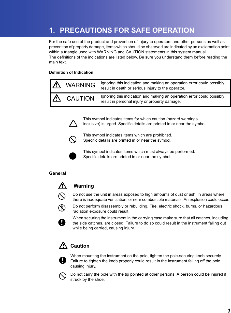
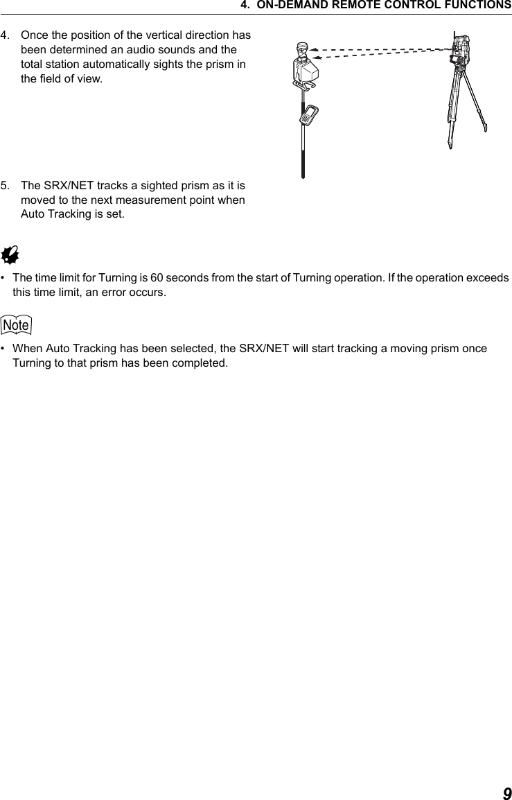
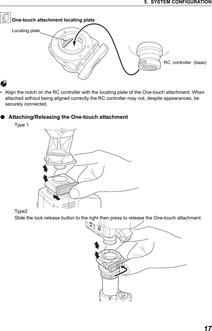
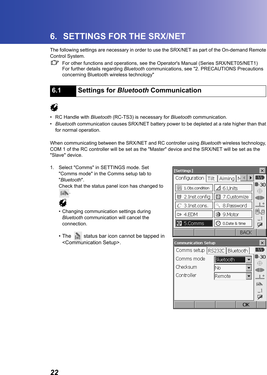
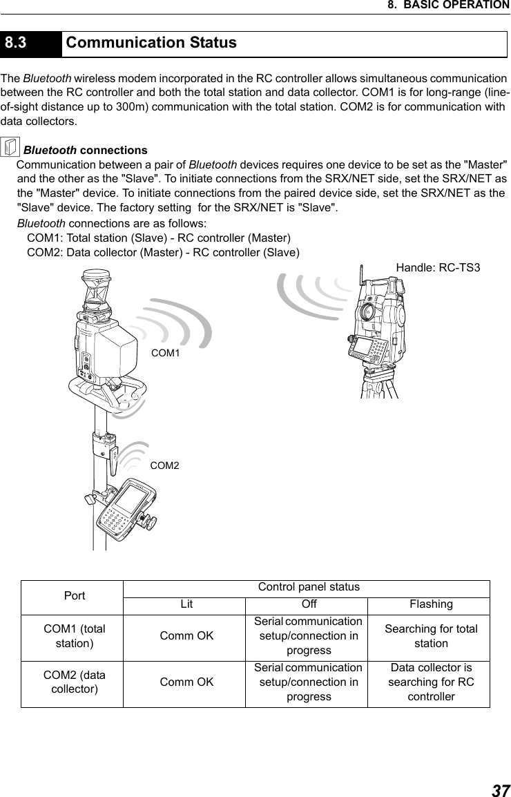
![236. SETTINGS FOR THE SRX/NET2. Select "Slave" as the SRX/NET mode and press [OK]. Selection can also be made by tapping the icon in the status panel until a menu appears.$• When communicating between a data collector and the RC controller using Bluetooth wireless technology, set COM 2 of the RC controller as the "Slave" device. Set the data collector as the "Master" device. C "8.3 Communication Status & Bluetooth connections"3. The display returns to Meas mode and SRX/NET enters "Waiting" mode. Check that the RC controller Bluetooth mode is set to "Master" and power ON to initiate a connection.C"9.3 Communication Setup for the RC Controller"4. When a connection has been successfully established is displayed in the status bar.•●COM1 on the RC controller control panel is lit.$•Press [Info] in the Bluetooth tab to display the Bluetooth device address.](https://usermanual.wiki/Sokkia-Topcon/WT11/User-Guide-863240-Page-29.png)
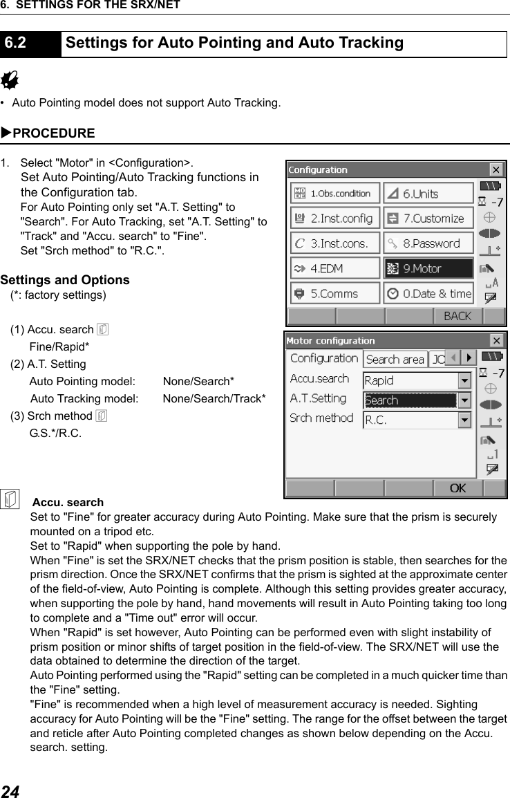
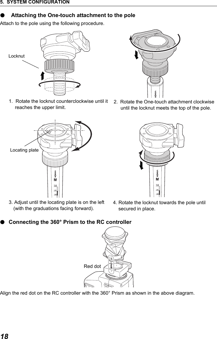
![256. SETTINGS FOR THE SRX/NET"Fine": ± 5" (approx.)"Rapid": ± 30" to ± 10’ (depending on distance)2. Set "Srch. method" to "R.C." in order to start Turning operation in response to a Turning command issued from the RC controller. Set to "G.S." to search for the target in the area specified in the Search area tab. 3. When neccessary, set the JOG dial turning speed for vertical and horizontal rotation of the telescope. The "Shift" point signifies the dial turning speed at which telescope rotation switches from the Lo speed setting to the Hi speed setting.This Shift point, along with the Lo and Hi speed settings can be configured according to user preference. Settings and Options(*: factory settings) (1) Lo1 to 4 (3*) (steps. 4 is fastest)(2) Hi 1 to 4 (3*) (steps. 4 is fastest)(3) Shift point1 to 4 (2*) (steps)Press [INIT] to return JOG Setting tab settings only to their factory settings. 4. Press [OK]. The larger the number set in (3) the further to the rightthe Shift point is set](https://usermanual.wiki/Sokkia-Topcon/WT11/User-Guide-863240-Page-31.png)
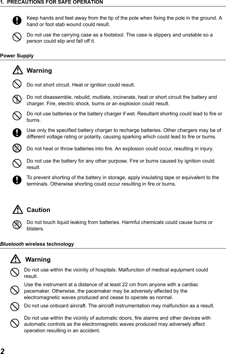
![6. SETTINGS FOR THE SRX/NET26It is possible to allocate SRX/NET softkeys for both designating the Turning direction, and issuing the instruction to start Turning.C For allocating softkey functions, see the Operator's Manual (Series SRX/NET05/NET1)●SRX softkey operation•[RC]: SRX/NET begins Turning directly in the direction of the RC controller.•[←RC] : SRX/NET begins Turning in a counterclockwise (left) direction (from the point of view of the operation panel).•[RC →]: SRX/NET begins Turning in a clockwise (right) direction (from the point of view of the operation panel).•[RC Cont]: Nullifies the current measurement position and continues Turning operation.The functions of the following softkeys change according to the settings made in "A. T. Setting" and "Srch method" in <Motor configuration>. When "Search" is set 6.3 Performing Turning from the SRX/NET "Motor" settingSoftkey When "Search" set in "A.T. Setting" When "None" set in "A.T. Setting""Srch method" is R.C. "Srch method" is G.S. (Global Search)[SRCH] Performs Auto Pointing [DIST] Performs Turning operation then angle/distance measurementPerforms Auto Pointing then angle/distance measurementPerforms angle and distance measurement[RC] Rotates directly in the direction of the RC controller then performs Auto Pointing[<-RC] Rotates in a counterclockwise direction (from the point of view of the RC controller) then performs Auto Pointing[RC->] Rotates in a clockwise direction (from the point of view of the RC controller) then performs Auto Pointing[RC Cont] Nullifes the current measurement position then continues Turning operation[←RC] [RC →]](https://usermanual.wiki/Sokkia-Topcon/WT11/User-Guide-863240-Page-32.png)
![276. SETTINGS FOR THE SRX/NET● When "Track" is set (Auto Tracking model only) *1: Pressing [AT On] when A.T. Setting is set to "None" will result in one of the following operations being performed. When "R.C." selected: Performs Turning operation then Auto TrackingWhen "G.S." selected: Performs Auto Pointing then Auto Tracking[AT On] (Auto Tracking model only)Performs Turning operation then Auto TrackingPerforms Auto Pointing then Auto TrackingPerforms Auto Tracking *1 "Motor" settingSoftkey When "Track" set in "A.T. Setting" When "None" set in "A.T. Setting""Srch method" is R.C. "Srch method" is G.S. (Global Search)[SRCH] Performs Auto Pointing then Auto Tracking Performs Auto Pointing[DIST] Performs Turning operation then distance measurement/Auto TrackingPerforms Auto Pointing then distance measurement/Auto TrackingPerforms angle and distance measurement[RC] Rotates directly in the direction of the RC controller then performs Auto PointingRotates in the direction specified by the RC controller then performs Auto Pointing[<-RC] Rotates in a counterclockwise direction (from the point of view of the RC controller) then performs Auto Pointing/Auto TrackingRotates in a counterclockwise direction (from the point of view of the RC controller) then performs Auto Pointing[RC->] Rotates in a clockwise direction (from the point of view of the RC controller) then performs Auto Pointing/Auto TrackingRotates in a clockwise direction (from the point of view of the RC controller) then performs Auto Pointing[RC Cont] Nullifes the current measurement position then continues Turning operation/Auto TrackingNullifes the current measurement position then continues Turning operation[AT On] Performs Turning operation then Auto TrackingPerforms Auto Pointing then Auto TrackingPerforms Auto Tracking *1](https://usermanual.wiki/Sokkia-Topcon/WT11/User-Guide-863240-Page-33.png)
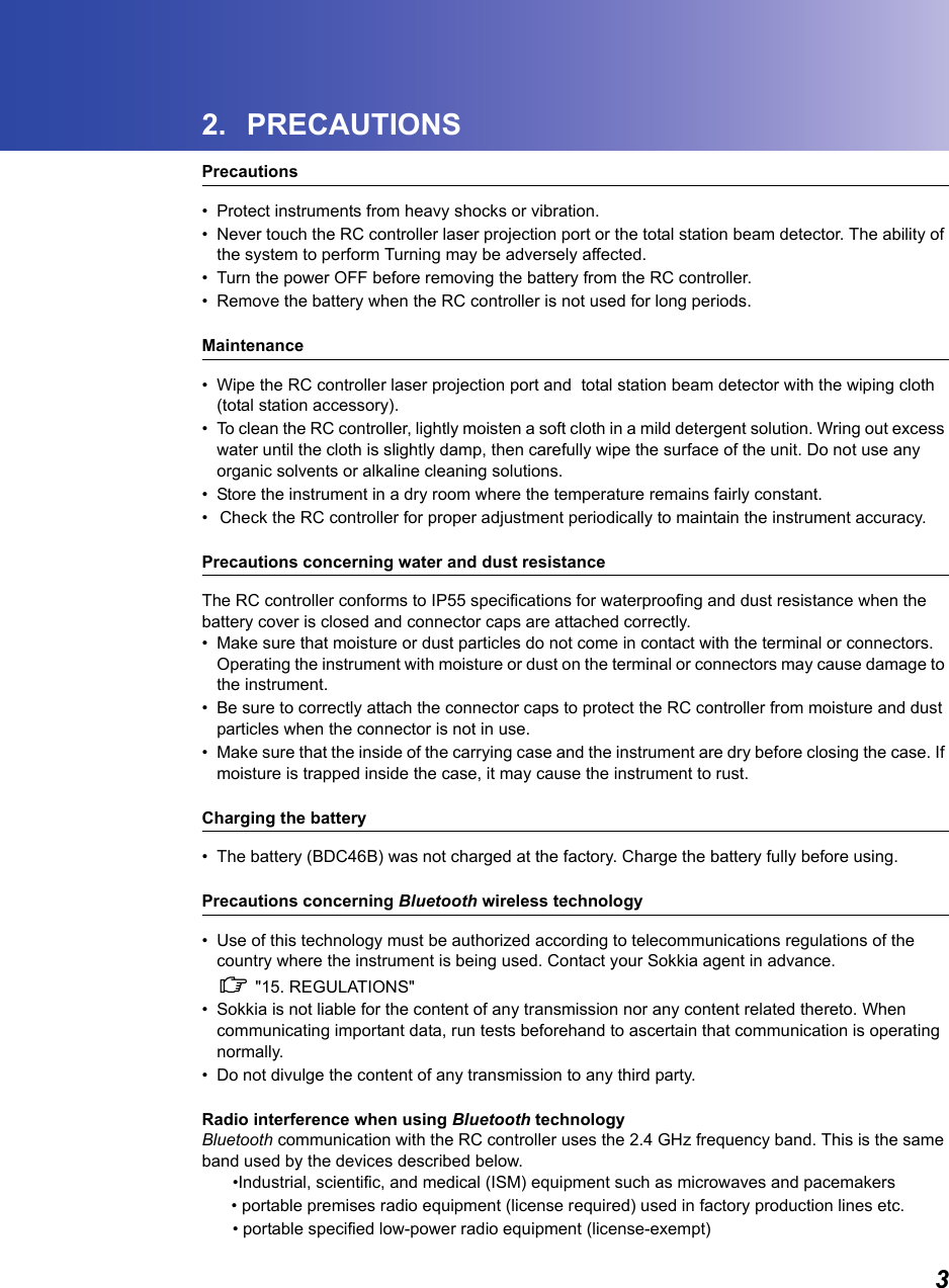
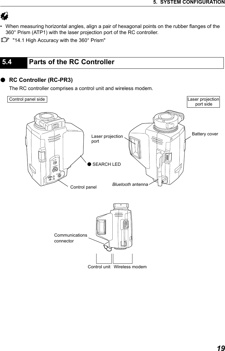
![6. SETTINGS FOR THE SRX/NET28When Turning fails to detect the prism, an error occursWhen the laser beam from the RC controller is reflected off an unrelated object the SRX/NET completes Turning operation pointing at the object instead of the RC controller. When this happens, press [RC Cont] to nullify the current measurement position and continue Turning operation.& Lost Prism (Auto Tracking model only)In the event that an obstacle prevents the SRX/NET sighting the target during Auto Tracking, the SRX/NET will predict the direction in which the target will travel and continue Auto Tracking based on this prediction. If the SRX/NET re-acquires the target in this predicted direction, Auto Tracking continues without change. If the target is not re-acquired however, Auto Tracking will stop and the SRX/NET will enter "prism wait" status for a period of 60 seconds. If the target enters the field of view or a Turning command is received from the RC controller during "prism wait", the SRX/NET will search for the prism, then resume Auto Tracking. If the target is not re-acquired during the "prism wait" period, the target is considered "lost" and Auto Tracking terminates. Start Turning procedure again. CFor error messages, see the Operator's Manual (Series SRX/NET05/NET1)6.4 Turning Error"Prism wait"Target "lost"Direction predictedAuto TrackingObstacleTar g e t Tar g e tTarget foundTarget foundnot foundnot found](https://usermanual.wiki/Sokkia-Topcon/WT11/User-Guide-863240-Page-34.png)
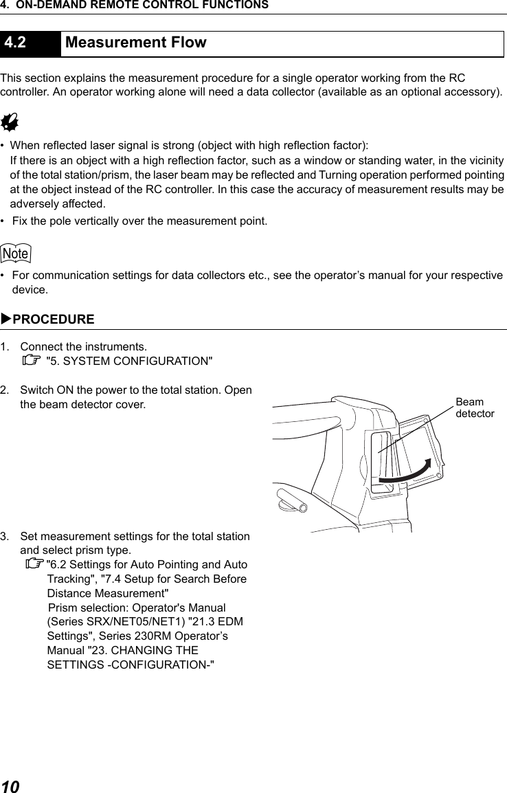
![7. APPENDED SETTINGS FOR THE SERIES 230RM30When using the On-demand Remote Control System, the communications setup for the Series 230RM, wireless modem, and data collector should be set as follows.G• To change the baud rate settings to values other than those shown above, contact your Sokkia agent.$• The baud rate of the RC controller can be switched using the dip switch. C "9.3 Communication Setup for the RC Controller"When the search before distance measurement option is set to "RC", the Turning function (SET rotation + Auto Point to detect prism) will be performed prior to distance measurement"Search": Auto Pointing only"RC": Turning "Off": No searchG• To perform measurement using the On-demand Remote Control System, the above setting must be set to "RC".• To perform measurement without using the RC controller, the above setting can be set to either "Search" or "Off". If it is set to "RC" by mistake, an error will occur as the Series 230RM tries to find the RC controller even though it is not in use.7.3 Communication SetupBaud rate 1200 bps or 9600 bpsData bits 8Stop bit 1Parity Non parity7.4 Setup for Search Before Distance Measurement[ OK ]Search bef.DIST:RCPCModeReflectEDM Fine "R":30mm:Prism Temp.Search area:HV WideEDM:Illum. hold:Laser 30 CPress. :1034hPappm :-300PPM[ OK ]](https://usermanual.wiki/Sokkia-Topcon/WT11/User-Guide-863240-Page-36.png)
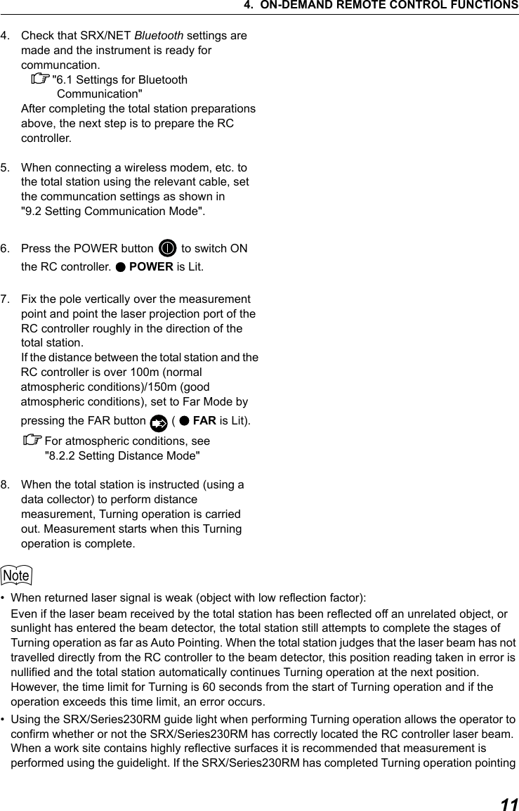
![317. APPENDED SETTINGS FOR THE SERIES 230RMIn the SFT Mode it is possible to both designate the Turning direction, and issue the instruction to start Turning.XPROCEDURE1. Press and hold {SFT} until the SFT Mode menu is displayed. Select "Motor menu" from the second page and press {I}.2. Select Turning command.• "Turn" - Series 230RM begins Turning directly towards the RC controller.• "Turn right" - Series 230RM begins Turning in a clockwise (right) direction (from the point of view of the operation panel).• "Turn left" - Series 230RM begins Turning in a counterclockwise (left) direction (from the point of view of the operation panel).3. To cancel Turning, press [STOP] during operation.7.5 Performing Turning from the Series 230RM SFT Mode .Aiming7. H angle set8. Data view9. Meas Motor menuEDITSFT menu. Tilt1. Search2. Face change3. Rotation4. Laser-pointer: OffSFT menu5.Turn6.Turn right7.Turn left"Turn left" "Turn right"](https://usermanual.wiki/Sokkia-Topcon/WT11/User-Guide-863240-Page-37.png)
![7. APPENDED SETTINGS FOR THE SERIES 230RM32It is possible to allocate softkeys to the [RC], [RC →], [←RC] functions.C For allocating softkey functions, see Series 230RM Operator’s ManualThe allocated softkeys are displayed in each measurement menu.•Press [RC] and the Series 230RM begins Turning directly towards the RC controller.•Press [←RC] and the Series 230RM begins Turning in a counterclockwise (left) direction (from the point of view of the operation panel).• Press [RC →] and the Series 230RM begins Turning in a clockwise (right) direction (from the point of view of the operation panel).7.6 Allocating Softkey Functions[ ]RCMeas./Sdist PC -30ppm 0DISTP1RCZA 89 57’42"HAR 359 01’20"RCS 15.120m[←RC] [RC →]](https://usermanual.wiki/Sokkia-Topcon/WT11/User-Guide-863240-Page-38.png)
![337. APPENDED SETTINGS FOR THE SERIES 230RMWhen Turning fails to detect the prism, an error occurs.When the laser beam from the RC controller is reflected off an unrelated object the Series 230RM completes Turning operation pointing at the object instead of the RC controller. When this happens, press [CONT] to nullify the current measurement position and continue Turning operation.For other softkeys, see "7.6 Allocating Softkey Functions"Remotocatcher Communication err !!Communication between the Series 230RM and RC controller has failed.Check the status (communications setup, power supply, cable connections etc.) of the RC controller, wireless modem and cables.Motor error E592Motor error E593A hardware error has occurred with the RC controller.Switch the power to the RC controller OFF and ON to correct the problem.If the error reoccurs after restart, contact your Sokkia agent. 7.7 Turning Error7.8 Error Messages](https://usermanual.wiki/Sokkia-Topcon/WT11/User-Guide-863240-Page-39.png)