Sokkia Topcon WT11 Bluetooth Module User Manual RC PR3 E
Sokkia Topcon Co., Ltd. Bluetooth Module RC PR3 E
User manual
SURVEYING INSTRUMENTS
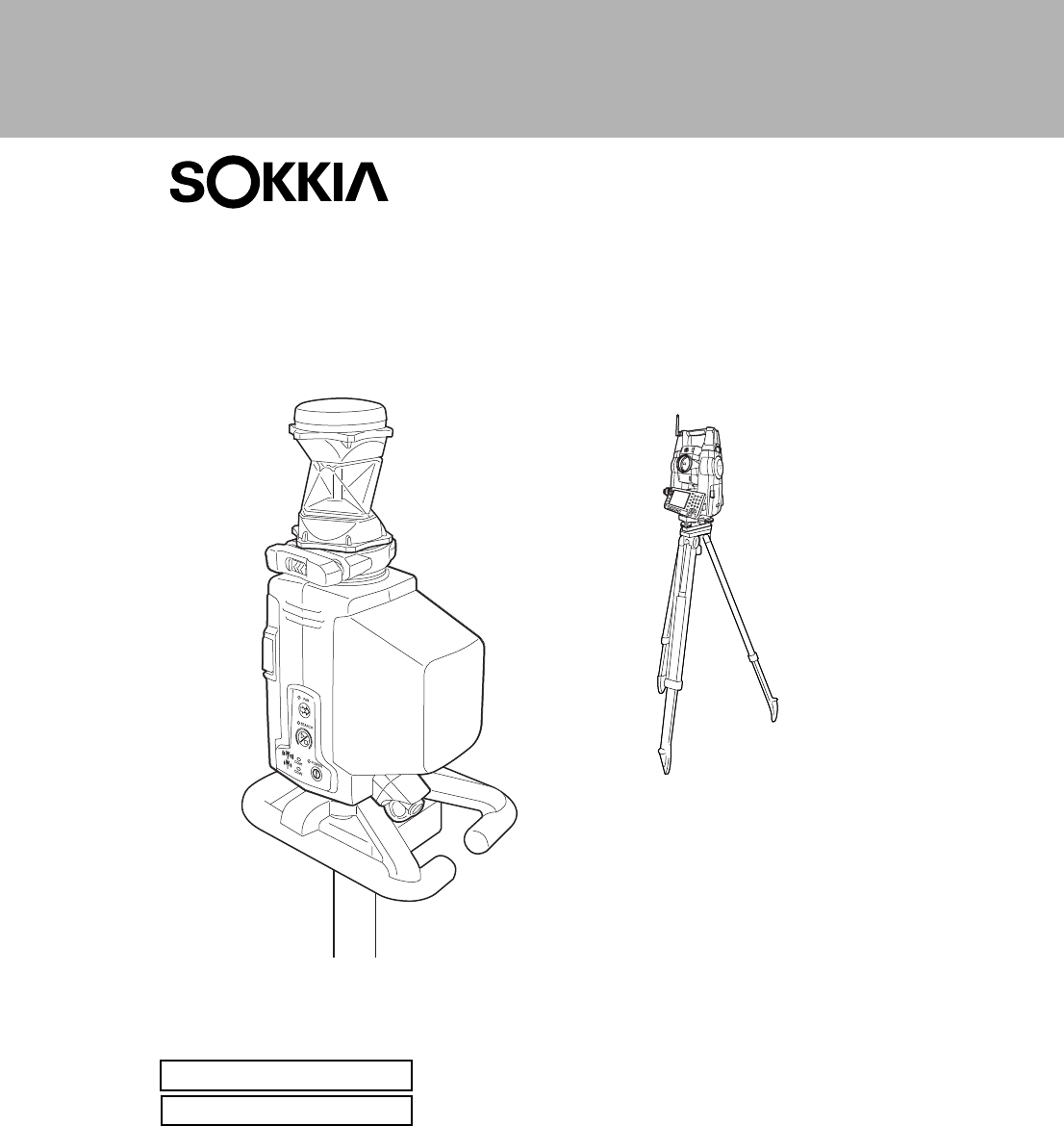
On-demand Remote Control System
SYSTEM MANUAL
RC-PR3
Class 1 LED Product
Class 1 Laser Product

:This is the mark of the Japan Surveying
Instruments Manufacturers Association.
Class 1 LED Product
Class 1 Laser Product
SURVEYING INSTRUMENTS
On-demand Remote Control System
RC-PR3
SYSTEM MANUAL
• Thank you for selecting the On-demand Remote Control System.
• Before using the instrument, please read this system manual carefully.
• The specifications and general appearance of the instrument may be altered at any
time and may differ from those appearing in brochures and this manual.
• Some of the diagrams shown in this manual may be simplified for easier
understanding.
• The On-demand Remote Control System adds remote control functions to the Series
SRX, NET05/NET1 and Series 230RM. Please read this manual in conjunction
with the operator’s manual for your instrument.

ii
HOW TO READ THIS MANUAL
Symbols
The following conventions are used in this manual.
G: Indicates precautions and important items which should be read before
operations.
C: Indicates a cross-reference to refer to for additional information.
$: Indicates supplementary explanation.
&: Indicates an explanation for a particular term or operation.
[DIST] etc. : Indicates softkeys on the total station display.
{ESC} etc. : Indicates operation keys on the total station.
I POWER etc. : Indicates RC controller LEDs.
Screens and illustrations
• Except where stated, "SRX" means Series SRX, "NET" means NET05 and NET1, "total station"
means "Series SRX/NET05/NET1/Series 230RM", and “RC controller” means the control unit for
the On-demand Remote Control System in this manual.
• The content of this system manual is mainly concerned with explaining the operation of the RC
controller. Appended functions for the SET are described in "7. APPENDED SETTINGS FOR THE
SERIES 230RM". For precautions and operating method, please read the Series 230RM Operator’s
Manual.
• Screens and illustrations used in this manual are of SRX (with RC-TS3 handle) or Series 230RM.

iii
CONTENTS
1. PRECAUTIONS FOR SAFE OPERATION ................ 1
2. PRECAUTIONS .......................................................... 3
3. LASER SAFETY INFORMATION ............................... 6
4. ON-DEMAND REMOTE CONTROL FUNCTIONS .... 7
4.1 Turning Operation Flow ..................................................... 8
4.2 Measurement Flow .......................................................... 10
5. SYSTEM CONFIGURATION .................................... 13
5.1 System Configuration of the SRX/NET ........................... 13
5.2 System Configuration of the Series 230RM .................... 14
5.3 System Configuration of the RC Controller ..................... 15
5.4 Parts of the RC Controller ............................................... 19
6. SETTINGS FOR THE SRX/NET .............................. 22
6.1 Settings for Bluetooth Communication ............................ 22
6.2 Settings for Auto Pointing and Auto Tracking ................. 24
6.3 Performing Turning from the SRX/NET ........................... 26
6.4 Turning Error ................................................................... 28
7. APPENDED SETTINGS FOR THE SERIES 230RM 29
7.1 Beam Detector ................................................................ 29
7.2 Attaching/Removing the Handle ...................................... 29
7.3 Setup for Search Before Distance Measurement ............ 30
7.4 Communication Setup ..................................................... 30
7.5 Performing Turning from the Series 230RM SFT Mode .. 31
7.6 Allocating Softkey Functions ........................................... 32
7.7 Error Messages ............................................................... 33
7.8 Turning Error ................................................................... 33
8. BASIC OPERATION ................................................. 34
8.1 Using the Battery ............................................................. 34
8.2 Button Operations ........................................................... 35
8.3 Communication Status .................................................... 37
9. RC CONTROLLER SETTINGS ................................ 38
9.1 Setting Auto Power-off .................................................... 38
9.2 Setting Communication Mode ......................................... 38
9.3 Communication Setup for the RC Controller ................... 39
9.4 Calibrating the Electronic Compass ................................ 39
10. ERROR INDICATIONS ........................................... 43

iv
CONTENTS
11. TROUBLESHOOTING ............................................. 44
12.
STANDARD EQUIPMENT AND OPTIONAL ACCESSORIES
46
12.1 Standard Equipment ....................................................... 46
12.2 Optional Accessories ...................................................... 46
12.3 Power Supply System ..................................................... 48
13. SPECIFICATIONS .................................................... 49
14. EXPLANATION ........................................................ 53
14.1 High Accuracy with the 360° Prism .................................. 53
15. REGULATIONS ........................................................ 54

1
1. PRECAUTIONS FOR SAFE OPERATION
For the safe use of the product and prevention of injury to operators and other persons as well as
prevention of property damage, items which should be observed are indicated by an exclamation point
within a triangle used with WARNING and CAUTION statements in this system manual.
The definitions of the indications are listed below. Be sure you understand them before reading the
main text.
Definition of Indication
General
CWARNING Ignoring this indication and making an operation error could possibly
result in death or serious injury to the operator.
CCAUTION Ignoring this indication and making an operation error could possibly
result in personal injury or property damage.
JThis symbol indicates items for which caution (hazard warnings
inclusive) is urged. Specific details are printed in or near the symbol.
DThis symbol indicates items which are prohibited.
Specific details are printed in or near the symbol.
IThis symbol indicates items which must always be performed.
Specific details are printed in or near the symbol.
CWarning
DDo not use the unit in areas exposed to high amounts of dust or ash, in areas where
there is inadequate ventilation, or near combustible materials. An explosion could occur.
GDo not perform disassembly or rebuilding. Fire, electric shock, burns, or hazardous
radiation exposure could result.
EWhen securing the instrument in the carrying case make sure that all catches, including
the side catches, are closed. Failure to do so could result in the instrument falling out
while being carried, causing injury.
CCaution
EWhen mounting the instrument on the pole, tighten the pole-securing knob securely.
Failure to tighten the knob properly could result in the instrument falling off the pole,
causing injury.
DDo not carry the pole with the tip pointed at other persons. A person could be injured if
struck by the shoe.

1. PRECAUTIONS FOR SAFE OPERATION
2
Power Supply
Bluetooth wireless technology
EKeep hands and feet away from the tip of the pole when fixing the pole in the ground. A
hand or foot stab wound could result.
DDo not use the carrying case as a footstool. The case is slippery and unstable so a
person could slip and fall off it.
CWarning
DDo not short circuit. Heat or ignition could result.
GDo not disassemble, rebuild, mutilate, incinerate, heat or short circuit the battery and
charger. Fire, electric shock, burns or an explosion could result.
DDo not use batteries or the battery charger if wet. Resultant shorting could lead to fire or
burns.
EUse only the specified battery charger to recharge batteries. Other chargers may be of
different voltage rating or polarity, causing sparking which could lead to fire or burns.
HDo not heat or throw batteries into fire. An explosion could occur, resulting in injury.
DDo not use the battery for any other purpose. Fire or burns caused by ignition could
result.
ETo prevent shorting of the battery in storage, apply insulating tape or equivalent to the
terminals. Otherwise shorting could occur resulting in fire or burns.
CCaution
FDo not touch liquid leaking from batteries. Harmful chemicals could cause burns or
blisters.
CWarning
DDo not use within the vicinity of hospitals. Malfunction of medical equipment could
result.
DUse the instrument at a distance of at least 22 cm from anyone with a cardiac
pacemaker. Otherwise, the pacemaker may be adversely affected by the
electromagnetic waves produced and cease to operate as normal.
DDo not use onboard aircraft. The aircraft instrumentation may malfunction as a result.
DDo not use within the vicinity of automatic doors, fire alarms and other devices with
automatic controls as the electromagnetic waves produced may adversely affect
operation resulting in an accident.

3
2. PRECAUTIONS
Precautions
• Protect instruments from heavy shocks or vibration.
• Never touch the RC controller laser projection port or the total station beam detector. The ability of
the system to perform Turning may be adversely affected.
• Turn the power OFF before removing the battery from the RC controller.
• Remove the battery when the RC controller is not used for long periods.
Maintenance
• Wipe the RC controller laser projection port and total station beam detector with the wiping cloth
(total station accessory).
• To clean the RC controller, lightly moisten a soft cloth in a mild detergent solution. Wring out excess
water until the cloth is slightly damp, then carefully wipe the surface of the unit. Do not use any
organic solvents or alkaline cleaning solutions.
• Store the instrument in a dry room where the temperature remains fairly constant.
• Check the RC controller for proper adjustment periodically to maintain the instrument accuracy.
Precautions concerning water and dust resistance
The RC controller conforms to IP55 specifications for waterproofing and dust resistance when the
battery cover is closed and connector caps are attached correctly.
• Make sure that moisture or dust particles do not come in contact with the terminal or connectors.
Operating the instrument with moisture or dust on the terminal or connectors may cause damage to
the instrument.
• Be sure to correctly attach the connector caps to protect the RC controller from moisture and dust
particles when the connector is not in use.
• Make sure that the inside of the carrying case and the instrument are dry before closing the case. If
moisture is trapped inside the case, it may cause the instrument to rust.
Charging the battery
• The battery (BDC46B) was not charged at the factory. Charge the battery fully before using.
Precautions concerning Bluetooth wireless technology
• Use of this technology must be authorized according to telecommunications regulations of the
country where the instrument is being used. Contact your Sokkia agent in advance.
C "15. REGULATIONS"
• Sokkia is not liable for the content of any transmission nor any content related thereto. When
communicating important data, run tests beforehand to ascertain that communication is operating
normally.
• Do not divulge the content of any transmission to any third party.
Radio interference when using Bluetooth technology
Bluetooth communication with the RC controller uses the 2.4 GHz frequency band. This is the same
band used by the devices described below.
•Industrial, scientific, and medical (ISM) equipment such as microwaves and pacemakers
• portable premises radio equipment (license required) used in factory production lines etc.
• portable specified low-power radio equipment (license-exempt)

2. PRECAUTIONS
4
•IEEE802.11b/IEEE802.11g standard wireless LAN devices
The above devices use the same frequency band as Bluetooth communications. As a result, using the
RC controller within proximity to the above devices may result in interference causing communication
failure or reduction of transmission speed.
Although a radio station license is not required for this instrument, bear in mind the following points
when using Bluetooth technology for communication.
●Regarding portable premises radio equipment and portable specified low-power radio
equipment:
• Before starting transmission, check that operation will not take place within the vicinity of portable
premises radio equipment or specified low-power radio equipment.
• In the case that the instrument causes radio interference with portable premises radio equipment,
terminate the connection immediately and take measures to prevent further interference (e.g.
connect using an interface cable).
• In the case that the instrument causes radio interference with portable specified low-power radio
equipment, contact your Sokkia agent.
●When using the RC controller in proximity to IEEE802.11b or IEEE802.11g standard wireless
LAN devices, turn off all devices not being used.
• Interference may result, causing transmission speed to slow or even disrupting the connection
completely. Turn off all devices not being used.
●Do not use the RC controller in proximity to microwaves.
• Microwave ovens can cause significant interference resulting in communication failure. Perform
communication at a distance of 3m or more from microwave ovens.
●Refrain from using the RC controller in proximity to televisions and radios.
• Televisions and radios use a different frequency band to Bluetooth communications.
However, even if the RC controller is used within proximity to the above equipment with no adverse
effects with regard to Bluetooth communication, moving a Bluetooth compatible device (including
the RC controller) closer to said equipment may result in electronic noise in sound or images,
adversely affecting the performance of televisions and radios.
Precautions regarding transmission
●For best results
• When using in conjunction with a total station, perform communication within a line-of-sight distance
of approximately 300m. The usable range becomes shorter when obstacles block the line of sight,
or devices other than total stations, such as PDAs or computers, are used. Wood, glass and plastic
will not impede communication but the usable range becomes shorter. Moreover, wood, glass
and plastic containing metal frames, plates, foil and other heat shielding elements as well as
coatings containing metallic powders may adversely affect Bluetooth communication and
concrete, reinforced concrete, and metal will render it impossible.
• Use a vinyl or plastic cover to protect the instrument from rain and moisture. Metallic materials
should not be used.
• The direction of the Bluetooth antenna can have adverse effects upon usable range. For best
results make sure that the antennas of both the RC controller and the companion device are
pointing towards one another.

5
2. PRECAUTIONS
●Reduced range due to atmospheric conditions
The radio waves used by the RC controller may be absorbed or scattered by rain, fog, and moisture
from the human body with the limit of usable range becoming lower as a result. Similarly, usable range
may also shorten when performing communication in wooded areas. Moreover, as wireless devices
lose signal strength when close to the ground, perform communication at as high a position as
possible.
G
• Sokkia cannot guarantee that all Bluetooth devices are compatible with the On-demand Remote
Control System.
6
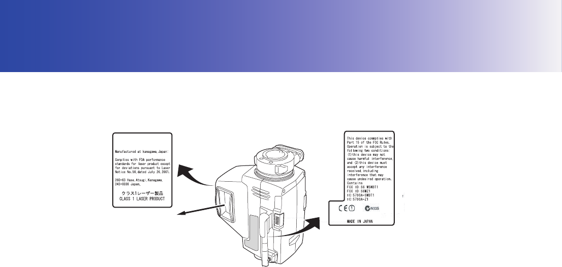
3. LASER SAFETY INFORMATION
RC controller is classified as a class 1 Laser Product and Class 1 LED Product according to IEC
Standard Publication 60825-1 Amd. 2: 2001 and United States Government Code of Federal
Regulation FDA CDRH 21CFR Part1040.10 and 1040.11 (Complies with FDA performance standards
for laser products except for deviations pursuant to Laser Notice No.50, dated July 26, 2001.)
CWarning
• Use of controls or adjustments or performance of procedures other than those specified herein may
result in hazardous radiation exposure.
• Never point the laser beam at another person. If the laser beam strikes skin or an eye, it could cause
serious injury.
• If an eye injury is caused by exposure to the laser beam, seek immediate medical attention from a
licensed ophthalmologist.
CCaution
• Perform checks at start of work and periodic checks and adjustments with the laser beam emitted
under normal conditions.
• When the instrument is not being used, turn OFF the power.
• When disposing of the instrument, destroy the battery connector so that the laser beam cannot be
emitted.
• Operate the instrument with due caution to avoid injuries that may be caused by the laser beam
unintentionally striking a person in the eye. Avoid setting the instrument at heights at which the path
of the laser beam may strike pedestrians or drivers at head height.
• Never point the laser beam at mirrors, windows or surfaces that are highly reflective. The reflected
laser beam could cause serious injury.
SOKKIA CO., LTD.
RC-PR3
SOKKIA CO., LTD.
Laser beam is emitted
from here
7
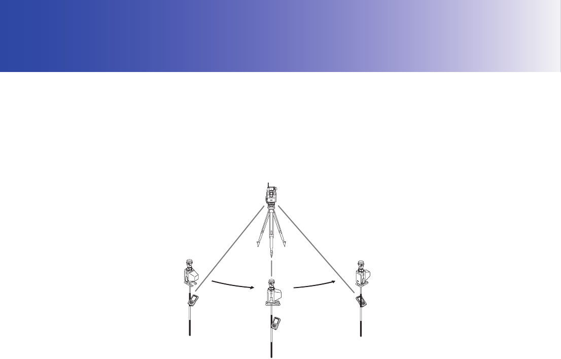
4. ON-DEMAND REMOTE CONTROL FUNCTIONS
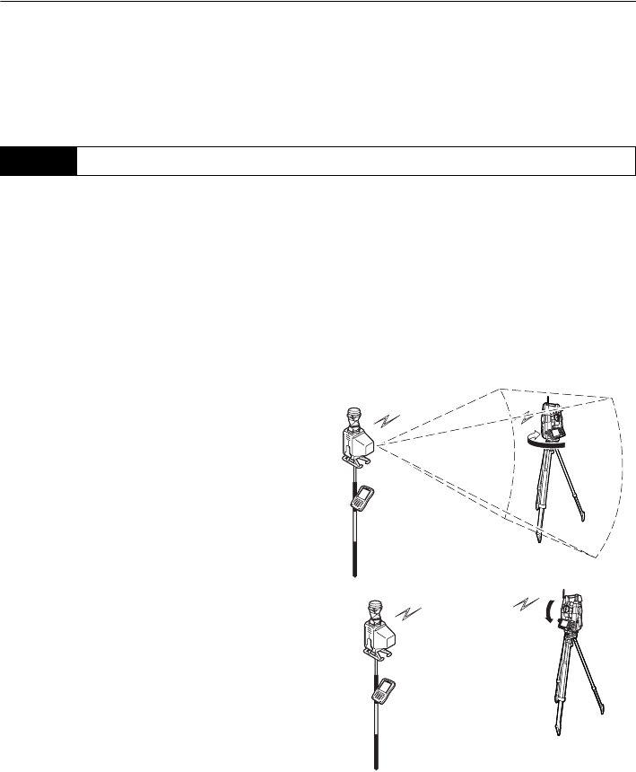
The On-demand Remote Control System works as follows. A laser is emitted from the laser projection
port on the RC controller. The total station rotates until its beam detector receives this beam. In this
way the total station is able to detect the position of the RC controller. This operation is called
"Turning".
With the On-demand Remote Control System it is possible for a single operator to perform
measurements, unaided, at multiple measurement points.
The RC controller incorporates a Bluetooth unit which allows simultaneous communication with both
the total station and a data collector.
&Electronic compass
The RC controller is equipped with an electronic compass. Using the Earth’s magnetism, this
compass can detect the RC controller’s horizontal angle from magnetic north.
The current angle is compared with that for the previous measurement to estimate the direction
in which the RC controller moved following the previous measurement. By then taking into
account the aspect of the telescope the RC controller can instruct the total station regarding the
quickest rotation direction to the prism.
The onboard electronic compass was calibrated before being shipped from the factory. A
function within the compass will automatically perform any necessary calibration in response to
changes in the magnetic field.
&Auto Pointing and Auto Tracking
When Auto Pointing is performed, the total station analyses the image of the prism in the field of
view and moves the telescope to sight the center of this prism. When used in conjunction with
the Auto Tracking function, the SRX/NET will then "track" the prism as it is moved to the next
measurement point. When the prism has been "lost" due to an obstacle in the line-of-sight or
operation has been interrupted, the On-demand Remote Control System allows you to quickly
resume operation where you left off.
4. ON-DEMAND REMOTE CONTROL FUNCTIONS
8
G
• Series SRX (Auto Pointing model) and Series 230RM do not support Auto Tracking. Auto Pointing
will be performed instead.
• Series 230RM does not support Auto Pointing with a 360° Prism (ATP1).
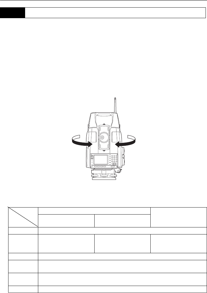
To perform Turning, follow the procedure below.
CFor measurement procedure, see "8. BASIC OPERATION"
1. Point the RC controller laser projection port
and prism in the direction of the total station
and instruct the instrument to start Turning. A
laser beam is emitted from the projection port.
At the same time, the Bluetooth unit (COM 1)
relays the instruction to begin Turning.
2. The total station begins to rotate horizontally,
searching for the emitted laser beam. If it is
not detected by the end of the second rotation,
an error occurs.
3. Once the position of the horizontal direction
has been determined, the total station
telescope then begins to rotate along the
vertical axis searching for the position of the
prism.
4.1 Turning Operation Flow
9
4. ON-DEMAND REMOTE CONTROL FUNCTIONS
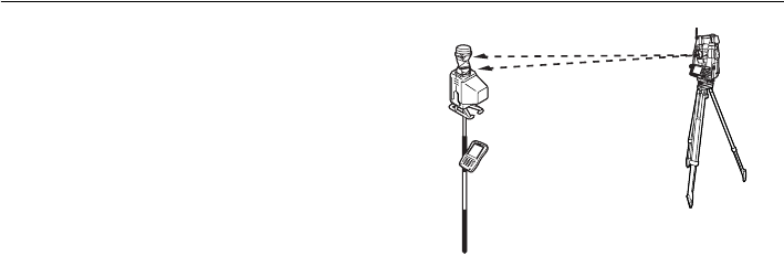
4. Once the position of the vertical direction has
been determined an audio sounds and the
total station automatically sights the prism in
the field of view.
5. The SRX/NET tracks a sighted prism as it is
moved to the next measurement point when
Auto Tracking is set.
G
• The time limit for Turning is 60 seconds from the start of Turning operation. If the operation exceeds
this time limit, an error occurs.
$
• When Auto Tracking has been selected, the SRX/NET will start tracking a moving prism once
Turning to that prism has been completed.
4. ON-DEMAND REMOTE CONTROL FUNCTIONS
10
This section explains the measurement procedure for a single operator working from the RC
controller. An operator working alone will need a data collector (available as an optional accessory).
G
• When reflected laser signal is strong (object with high reflection factor):
If there is an object with a high reflection factor, such as a window or standing water, in the vicinity
of the total station/prism, the laser beam may be reflected and Turning operation performed pointing
at the object instead of the RC controller. In this case the accuracy of measurement results may be
adversely affected.
• Fix the pole vertically over the measurement point.
$
• For communication settings for data collectors etc., see the operator’s manual for your respective
device.
XPROCEDURE
1. Connect the instruments.
C "5. SYSTEM CONFIGURATION"
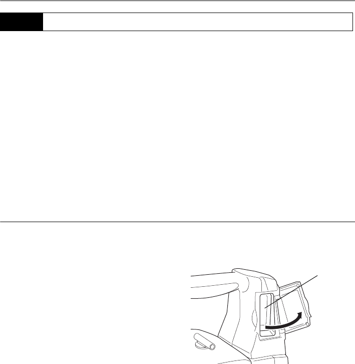
2. Switch ON the power to the total station. Open
the beam detector cover.
3. Set measurement settings for the total station
and select prism type.
C"6.2 Settings for Auto Pointing and Auto
Tracking", "7.4 Setup for Search Before
Distance Measurement"
Prism selection: Operator's Manual
(Series SRX/NET05/NET1) "21.3 EDM
Settings", Series 230RM Operator’s
Manual "23. CHANGING THE
SETTINGS -CONFIGURATION-"
4.2 Measurement Flow
Beam
detector
11
4. ON-DEMAND REMOTE CONTROL FUNCTIONS
4. Check that SRX/NET Bluetooth settings are
made and the instrument is ready for
communcation.
C"6.1 Settings for Bluetooth
Communication"
After completing the total station preparations
above, the next step is to prepare the RC
controller.
5. When connecting a wireless modem, etc. to
the total station using the relevant cable, set
the communcation settings as shown in
"9.2 Setting Communication Mode".
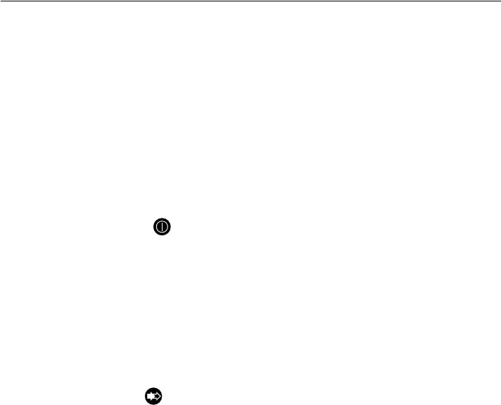
6. Press the POWER button to switch ON
the RC controller. ●POWER is Lit.
7. Fix the pole vertically over the measurement
point and point the laser projection port of the
RC controller roughly in the direction of the
total station.
If the distance between the total station and the
RC controller is over 100m (normal
atmospheric conditions)/150m (good
atmospheric conditions), set to Far Mode by
pressing the FAR button (●FAR is Lit).
CFor atmospheric conditions, see
"8.2.2 Setting Distance Mode"
8. When the total station is instructed (using a
data collector) to perform distance
measurement, Turning operation is carried
out. Measurement starts when this Turning
operation is complete.
$
• When returned laser signal is weak (object with low reflection factor):
Even if the laser beam received by the total station has been reflected off an unrelated object, or
sunlight has entered the beam detector, the total station still attempts to complete the stages of
Turning operation as far as Auto Pointing. When the total station judges that the laser beam has not
travelled directly from the RC controller to the beam detector, this position reading taken in error is
nullified and the total station automatically continues Turning operation at the next position.
However, the time limit for Turning is 60 seconds from the start of Turning operation and if the
operation exceeds this time limit, an error occurs.
• Using the SRX/Series230RM guide light when performing Turning operation allows the operator to
confirm whether or not the SRX/Series230RM has correctly located the RC controller laser beam.
When a work site contains highly reflective surfaces it is recommended that measurement is
performed using the guidelight. If the SRX/Series230RM has completed Turning operation pointing
4. ON-DEMAND REMOTE CONTROL FUNCTIONS
12
at the RC controller, both the red and green guide lights are visible from the position of the RC
controller.
C For the total station guide light, see the Series SRX Operator’s Manual/Series 230RM
Operator’s Manual
• With data collectors it is possible to specify the rotation direction for Turning operation before
performing distance measurement.
C For operation procedure, see the operator's manual for your data collector.
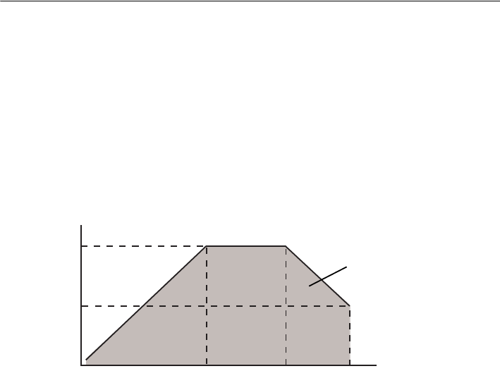
& Height difference and slope distance
The maximum measuring range depends on the height difference between the total station and
the RC controller.
The shaded area in the graph below represents the measurement range when set to Far Mode.
40m
20m
180m 250m 300m
Height difference
Measurement
range
Slope distance
13
5. SYSTEM CONFIGURATION
The following chapter explains the configuration of total stations and prisms.
Always open the beam detector cover when using the On-demand Remote Control System.
G
• The beam detector cover can be damaged if forced open beyond a certain angle. Always close the
beam detector cover before moving the instrument.
& Using a wireless modem
Serial communication settings must be configured on the RC controller when using a wireless
modem. C"9.2 Setting Communication Mode", "9.3 Communication Setup for the RC
Controller"
Make sure the power of all instruments is off before connecting. If the total station and RC
controller are not connected correctly, normal operation cannot be carried out.
Handle cables with care. Grip the connected end of the cable when disconnecting. Do not pull
the cable out with undue force.
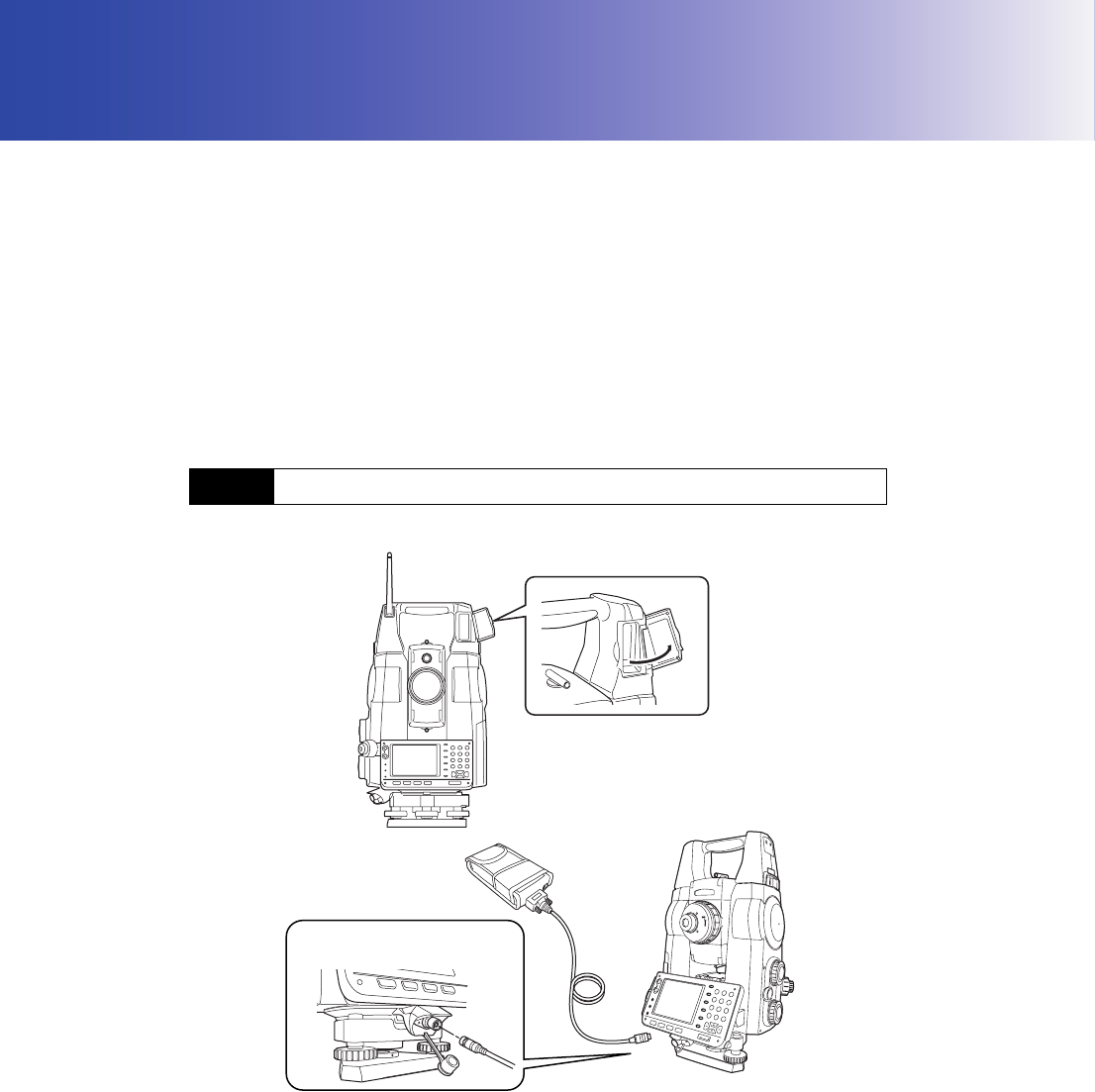
●SRX/NET instrument compatible with On-demand Remote Control System
5.1 System Configuration of the SRX/NET
Series SRX
Wireless modem
Communications and power supply
connector
Handle: RC-TS3
Handle: RC-TS3A
5. SYSTEM CONFIGURATION
14
G
• Only instruments incorporating a handle equipped with a beam detector (RC-TS3 or RC-TS3A) can
be used with the On-demand Remote Control System.
• For details regarding wireless modems compatible with an SRX/NET instrument with the RC-TS3A
handle, contact your Sokkia agent.
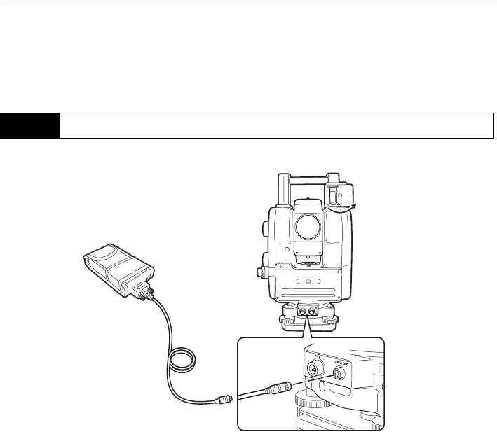
●Series 230RM instrument compatible with On-demand Remote Control System
G
• For details regarding data collectors and wireless modems compatible with the On-demand Remote
Control System, contact your Sokkia agent.
• Make sure the power of the date collector is off before connecting to the serial cable.
• Series 230RM does not support Auto Pointing with a 360° Prism (ATP1).
5.2 System Configuration of the Series 230RM
Series 230RM
Wireless modem
15
5. SYSTEM CONFIGURATION
For use with other prism types, contact your Sokkia agent.
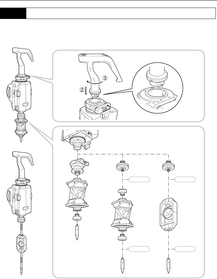
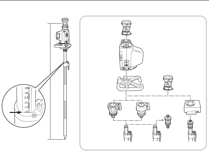
●Grip type
5.3 System Configuration of the RC Controller
RC
Trigger grip for RC-PR3
One-touch Adapter
Adapter
Stainless-steel
Pin-pole
Pin-pole
Pin-pole
Pin-pole
prism foot
AP66
SB184
Adapter
Adapter
SB184
Adapter
SB184
360° Prism
ATP1
360° Prism
ATP1
Pin-pole
Prism
OR1PA
attachment
SB182A
SB183 SB183
RC-PR3
RC-PRH3
Controller
&
5. SYSTEM CONFIGURATION
16
●Pole type
Whichever pole/One-touch attachment combination is used, the height to the SB179/SB179A flange
face is the same.
G
• When using the 0R1PA mini prism, the instrument should be set up so that the prism and the RC
controller laser projection port are pointing in the same direction.
$
• The combination of the SB179 and AP65B/65C is possible if Precise Tip of the AP65 is transferred
to the AP65B/65C.
• The One-touch attachment (SB179/SB179A) can also be used to connect the 360° Prism (ATP1)
directly to the pole (i.e. when the RC-PR3 is not used).
Protector
RP2
360° Prism
RC controller
attachment
One-touch
Pole
RC-PR3
ATP1
The pole reading shows
AP65B/65C AP65/65A
SB179
SB179ASB179A
the height from the bottom
of the pole shoe to the
center of the 360° Prism
(ATP1) when using the
&
360° Prism
ATP1
AP65/65A
configuration shown at
right.
17
5. SYSTEM CONFIGURATION
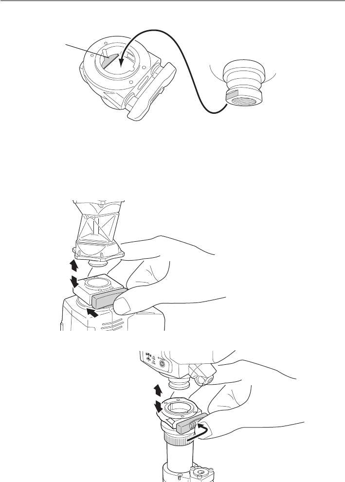
& One-touch attachment locating plate
G
• Align the notch on the RC controller with the locating plate of the One-touch attachment. When
attached without being aligned correctly the RC controller may not, despite appearances, be
securely connected.
●Attaching/Releasing the One-touch attachment
Type 1
Type2
Slide the lock release button to the right then press to release the One-touch attachment.
Locating plate
RC controller (base)
5. SYSTEM CONFIGURATION
18
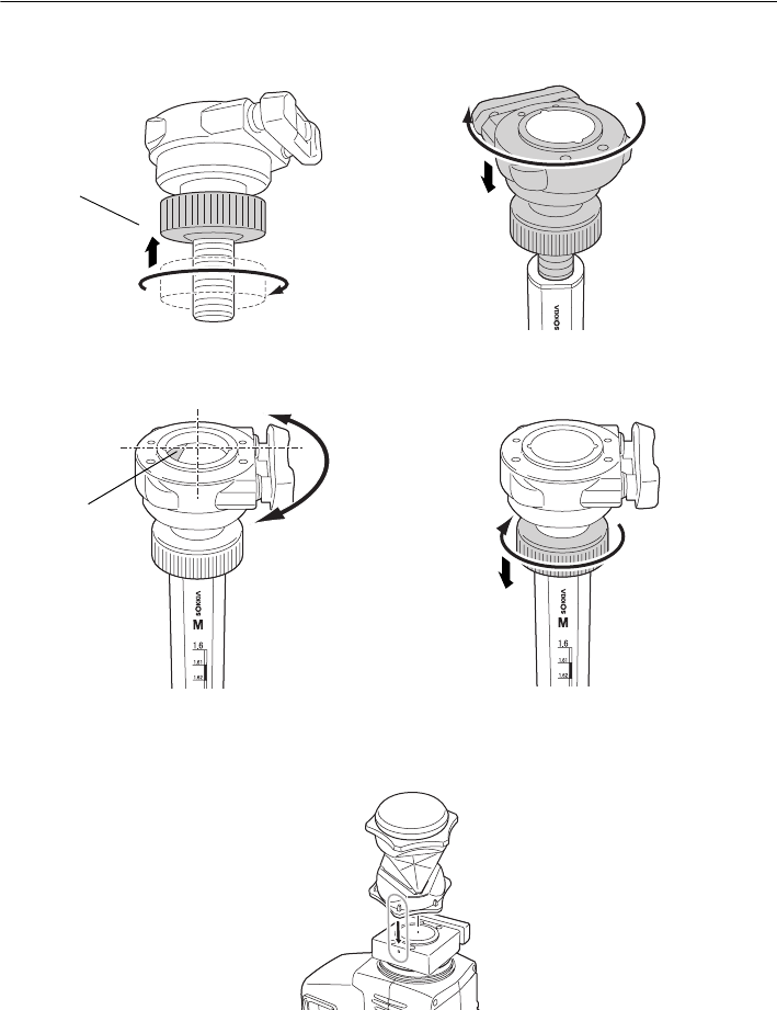
● Attaching the One-touch attachment to the pole
Attach to the pole using the following procedure.
1. Rotate the locknut counterclockwise until it
reaches the upper limit.
3. Adjust until the locating plate is on the left
(with the graduations facing forward).
●Connecting the 360° Prism to the RC controller
Align the red dot on the RC controller with the 360° Prism as shown in the above diagram.
Locknut
2. Rotate the One-touch attachment clockwise
until the locknut meets the top of the pole.
Locating plate
4. Rotate the locknut towards the pole until
secured in place.
Red dot
19
5. SYSTEM CONFIGURATION
G
• When measuring horizontal angles, align a pair of hexagonal points on the rubber flanges of the
360° Prism (ATP1) with the laser projection port of the RC controller.
C"14.1 High Accuracy with the 360° Prism"
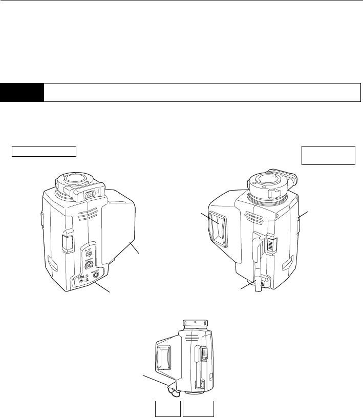
●RC Controller (RC-PR3)
The RC controller comprises a control unit and wireless modem.
5.4 Parts of the RC Controller
Bluetooth antenna
Control panel
Communications
Laser projection Battery cover
Control panel side Laser projection
port side
port
Control unit Wireless modem
●SEARCH LED
connector
5. SYSTEM CONFIGURATION
20
●Bluetooth antenna
Point the antenna in the direction of the paired device when performing communication using
Bluetooth wireless technology. The antenna is designed for long-range (line-of-sight distance up
to 300m under good communication conditions) communication with the total station. When the
antennas of the SRX/NET and RC controller cannot be positioned so as to be visible to one
another, point in a vertically downward position.
$
• Communication with data collectors is performed using a second (internal) antenna. The usable
range of this modem is a line-of-sight distance up to approx. 2m.
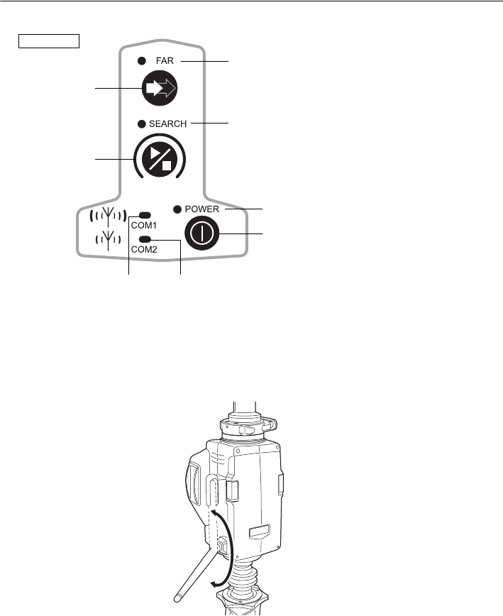
●FAR
●SEARCH
●POWER
FAR button
SEARCH button
POWER button
●COM1 ●COM2
Control panel
21
5. SYSTEM CONFIGURATION
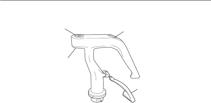
●Trigger Grip (RC-PRH3)
The trigger grip incorporates a trigger key and circular level.
& Trigger key
Pressing the trigger key performs the same operation as the Read Key on your data collector’s
SDR+ software. In order to use this function, communication between the RC-PR3 (with trigger
grip attached) and the data collector is necessary. This communication can be performed using
a serial connection (RS232C) or via Bluetooth wireless technology.
& Adjusting the circular level
First attach the trigger grip to the RC-PR3, and then attach the RC-PR3 to the instrument height
adapter (AP41) etc. Holding the trigger grip, keep the instrument level. Check the position of the
bubble of the circular level. If the bubble is not off-center, no adjustment is necessary. If the
bubble is off-center, perform the following adjustment. First confirm the off-center direction. Use
the adjusting pin to loosen the circular level adjustment screw on the side opposite to the
direction the bubble is displaced to move the bubble to the center. Adjust the adjusting screws
until the tightening tension of the three screws is the same to align the bubble in the middle of
the circle.
Circular level Trigger key
Circular level
Strap
adjusting screws
22
6. SETTINGS FOR THE SRX/NET
The following settings are necessary in order to use the SRX/NET as part of the On-demand Remote
Control System.
CFor other functions and operations, see the Operator's Manual (Series SRX/NET05/NET1)
For further details regarding Bluetooth communications, see "2. PRECAUTIONS Precautions
concerning Bluetooth wireless technology"
G
• RC Handle with Bluetooth (RC-TS3) is necessary for Bluetooth communication.
•Bluetooth communication causes SRX/NET battery power to be depleted at a rate higher than that
for normal operation.
When communicating between the SRX/NET and RC controller using Bluetooth wireless technology,
COM 1 of the RC controller will be set as the "Master" device and the SRX/NET will be set as the
"Slave" device.
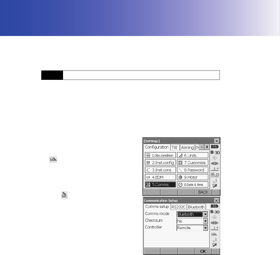
1. Select "Comms" in SETTINGS mode. Set
"Comms mode" in the Comms setup tab to
"Bluetooth".
Check that the status panel icon has changed to
.
G
• Changing communication settings during
Bluetooth communication will cancel the
connection.
• The status bar icon cannot be tapped in
<Communication Setup>.
6.1 Settings for Bluetooth Communication
23
6. SETTINGS FOR THE SRX/NET
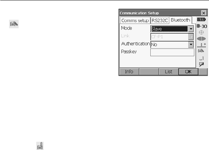
2. Select "Slave" as the SRX/NET mode and press
[OK]. Selection can also be made by tapping the
icon in the status panel until a menu
appears.
$
• When communicating between a data
collector and the RC controller using
Bluetooth wireless technology, set COM 2 of
the RC controller as the "Slave" device. Set
the data collector as the "Master" device.
C "8.3 Communication Status & Bluetooth
connections"
3. The display returns to Meas mode and SRX/NET
enters "Waiting" mode. Check that the RC
controller Bluetooth mode is set to "Master" and
power ON to initiate a connection.
C"9.3 Communication Setup for the RC
Controller"
4. When a connection has been successfully
established is displayed in the status bar.
•●COM1 on the RC controller control panel is lit.
$
•Press [Info] in the Bluetooth tab to display the Bluetooth device address.
6. SETTINGS FOR THE SRX/NET
24
G
• Auto Pointing model does not support Auto Tracking.
XPROCEDURE
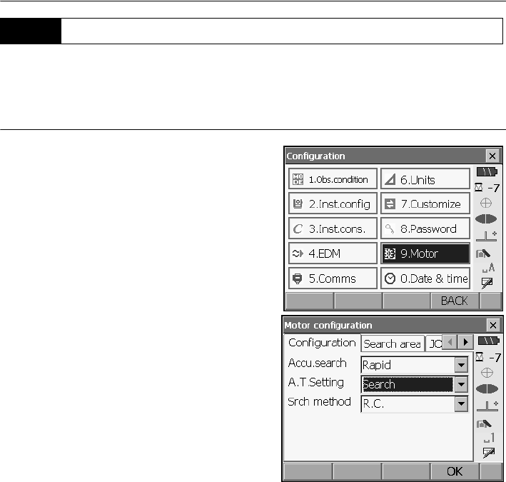
1. Select "Motor" in <Configuration>.
Set Auto Pointing/Auto Tracking functions in
the Configuration tab.
For Auto Pointing only set "A.T. Setting" to
"Search". For Auto Tracking, set "A.T. Setting" to
"Track" and "Accu. search" to "Fine".
Set "Srch method" to "R.C.".
Settings and Options
(*: factory settings)
(1) Accu. search &
Fine/Rapid*
(2) A.T. Setting
Auto Pointing model: None/Search*
Auto Tracking model: None/Search/Track*
(3) Srch method &
G.S.*/R.C.
& Accu. search
Set to "Fine" for greater accuracy during Auto Pointing. Make sure that the prism is securely
mounted on a tripod etc.
Set to "Rapid" when supporting the pole by hand.
When "Fine" is set the SRX/NET checks that the prism position is stable, then searches for the
prism direction. Once the SRX/NET confirms that the prism is sighted at the approximate center
of the field-of-view, Auto Pointing is complete. Although this setting provides greater accuracy,
when supporting the pole by hand, hand movements will result in Auto Pointing taking too long
to complete and a "Time out" error will occur.
When "Rapid" is set however, Auto Pointing can be performed even with slight instability of
prism position or minor shifts of target position in the field-of-view. The SRX/NET will use the
data obtained to determine the direction of the target.
Auto Pointing performed using the "Rapid" setting can be completed in a much quicker time than
the "Fine" setting.
"Fine" is recommended when a high level of measurement accuracy is needed. Sighting
accuracy for Auto Pointing will be the "Fine" setting. The range for the offset between the target
and reticle after Auto Pointing completed changes as shown below depending on the Accu.
search. setting.
6.2 Settings for Auto Pointing and Auto Tracking
25
6. SETTINGS FOR THE SRX/NET
"Fine": ± 5" (approx.)
"Rapid": ± 30" to ± 10’ (depending on distance)
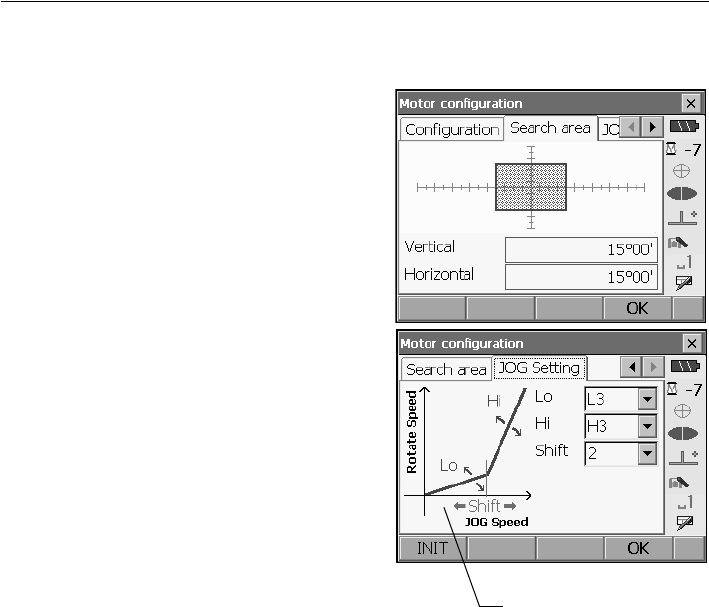
2. Set "Srch. method" to "R.C." in order to start
Turning operation in response to a Turning
command issued from the RC controller.
Set to "G.S." to search for the target in the area
specified in the Search area tab.
3. When neccessary, set the JOG dial turning speed
for vertical and horizontal rotation of the
telescope. The "Shift" point signifies the dial
turning speed at which telescope rotation
switches from the Lo speed setting to the Hi
speed setting.This Shift point, along with the Lo
and Hi speed settings can be configured
according to user preference.
Settings and Options
(*: factory settings)
(1) Lo
1 to 4 (3*) (steps. 4 is fastest)
(2) Hi
1 to 4 (3*) (steps. 4 is fastest)
(3) Shift point
1 to 4 (2*) (steps)
Press [INIT] to return JOG Setting tab settings
only to their factory settings.
4. Press [OK].
The larger the number set
in (3) the further to the right
the Shift point is set
6. SETTINGS FOR THE SRX/NET
26
It is possible to allocate SRX/NET softkeys for both designating the Turning direction, and issuing the
instruction to start Turning.
C For allocating softkey functions, see the Operator's Manual (Series SRX/NET05/NET1)
●SRX softkey operation
•[RC]: SRX/NET begins Turning directly in the direction of the RC controller.
•[←RC] : SRX/NET begins Turning in a counterclockwise (left) direction (from the point of
view of the operation panel).
•[RC →]: SRX/NET begins Turning in a clockwise (right) direction (from the point of view of
the operation panel).
•[RC Cont]: Nullifies the current measurement position and continues Turning operation.
The functions of the following softkeys change according to the settings made in "A. T. Setting" and
"Srch method" in <Motor configuration>.
When "Search" is set
6.3 Performing Turning from the SRX/NET
"Motor"
setting
Softkey
When "Search" set in "A.T. Setting" When "None" set in
"A.T. Setting"
"Srch method" is R.C. "Srch method" is G.S.
(Global Search)
[SRCH] Performs Auto Pointing
[DIST] Performs Turning
operation then angle/
distance measurement
Performs Auto Pointing
then angle/distance
measurement
Performs angle and
distance measurement
[RC] Rotates directly in the direction of the RC controller then performs Auto Pointing
[<-RC] Rotates in a counterclockwise direction (from the point of view of the RC
controller) then performs Auto Pointing
[RC->] Rotates in a clockwise direction (from the point of view of the RC controller) then
performs Auto Pointing
[RC Cont] Nullifes the current measurement position then continues Turning operation
[←RC] [RC →]

27
6. SETTINGS FOR THE SRX/NET
● When "Track" is set (Auto Tracking model only)
*1: Pressing [AT On] when A.T. Setting is set to "None" will result in one of the following operations
being performed.
When "R.C." selected: Performs Turning operation then Auto Tracking
When "G.S." selected: Performs Auto Pointing then Auto Tracking
[AT On]
(Auto
Tracking
model only)
Performs Turning
operation then Auto
Tracking
Performs Auto Pointing
then Auto Tracking
Performs Auto Tracking
*1
"Motor"
setting
Softkey
When "Track" set in "A.T. Setting" When "None" set in
"A.T. Setting"
"Srch method" is R.C. "Srch method" is G.S.
(Global Search)
[SRCH] Performs Auto Pointing then Auto Tracking Performs Auto Pointing
[DIST] Performs Turning
operation then distance
measurement/Auto
Tracking
Performs Auto Pointing
then distance
measurement/Auto
Tracking
Performs angle and
distance measurement
[RC] Rotates directly in the direction of the RC controller
then performs Auto Pointing
Rotates in the direction
specified by the RC
controller then performs
Auto Pointing
[<-RC] Rotates in a counterclockwise direction (from the
point of view of the RC controller) then performs Auto
Pointing/Auto Tracking
Rotates in a
counterclockwise
direction (from the point
of view of the RC
controller) then performs
Auto Pointing
[RC->] Rotates in a clockwise direction (from the point of
view of the RC controller) then performs Auto
Pointing/Auto Tracking
Rotates in a clockwise
direction (from the point
of view of the RC
controller) then performs
Auto Pointing
[RC Cont] Nullifes the current measurement position then
continues Turning operation/Auto Tracking
Nullifes the current
measurement position
then continues Turning
operation
[AT On] Performs Turning
operation then Auto
Tracking
Performs Auto Pointing
then Auto Tracking
Performs Auto Tracking
*1
6. SETTINGS FOR THE SRX/NET
28
When Turning fails to detect the prism, an error occurs
When the laser beam from the RC controller is reflected off an unrelated object the SRX/NET
completes Turning operation pointing at the object instead of the RC controller. When this happens,
press [RC Cont] to nullify the current measurement position and continue Turning operation.
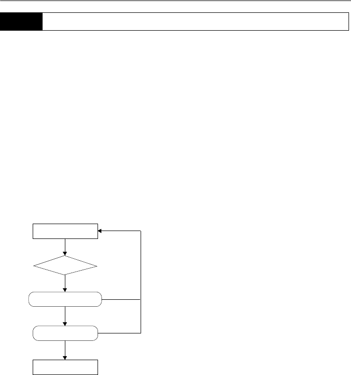
& Lost Prism (Auto Tracking model only)
In the event that an obstacle prevents the SRX/NET sighting the target during Auto Tracking,
the SRX/NET will predict the direction in which the target will travel and continue Auto Tracking
based on this prediction. If the SRX/NET re-acquires the target in this predicted direction, Auto
Tracking continues without change. If the target is not re-acquired however, Auto Tracking will
stop and the SRX/NET will enter "prism wait" status for a period of 60 seconds. If the target
enters the field of view or a Turning command is received from the RC controller during "prism
wait", the SRX/NET will search for the prism, then resume Auto Tracking. If the target is not re-
acquired during the "prism wait" period, the target is considered "lost" and Auto Tracking
terminates.
Start Turning procedure again.
CFor error messages, see the Operator's Manual (Series SRX/NET05/NET1)
6.4 Turning Error
"Prism wait"
Target "lost"
Direction predicted
Auto Tracking
Obstacle
Tar g e t
Tar g e t
Target found
Target found
not found
not found
29
7. APPENDED SETTINGS FOR THE SERIES 230RM
In order to be used as part of the On-demand Remote Control System, the Series 230RM was modifed
to include the new functions described below.
C For other functions, see Series 230RM Operator’s Manual
G
• Series 230RM does not support Auto Tracking. Auto Pointing will be performed instead.
• Series 230RM does not support Auto Pointing with a 360° Prism (ATP1).
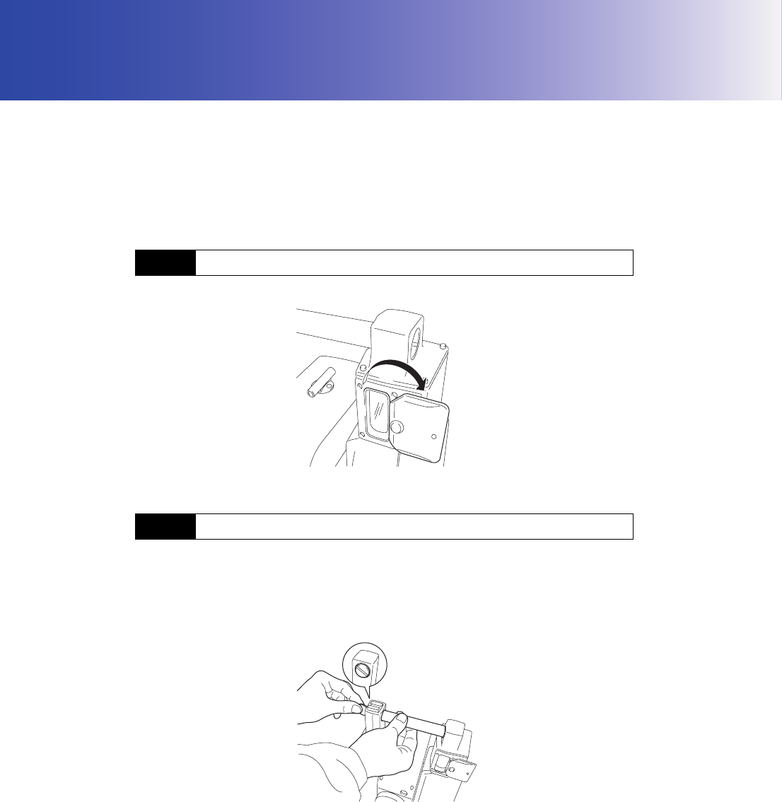
Open the beam detector cover when using the On-demand Remote Control System.
When measurement is complete, make sure that the beam detector cover is closed before placing the
instrument in its case.
The handle is attached/removed using the screw located at the opposite end of the handle to the beam
detector.
Supporting the handle with one hand, use a coin to loosen the screw until the handle can be removed.
To attach, align the ridge on the handle with the groove in the screw section and insert the handle so
that it covers the screw. Use a coin to tighten the screw until the handle is secured.
7.1 Beam Detector
7.2 Attaching/Removing the Handle
7. APPENDED SETTINGS FOR THE SERIES 230RM
30
When using the On-demand Remote Control System, the communications setup for the Series
230RM, wireless modem, and data collector should be set as follows.
G
• To change the baud rate settings to values other than those shown above, contact your Sokkia
agent.
$
• The baud rate of the RC controller can be switched using the dip switch.
C "9.3 Communication Setup for the RC Controller"
When the search before distance measurement option is set to "RC", the Turning function (SET
rotation + Auto Point to detect prism) will be performed prior to distance measurement
"Search": Auto Pointing only
"RC": Turning
"Off": No search
G
• To perform measurement using the On-demand Remote Control System, the above setting must be
set to "RC".
• To perform measurement without using the RC controller, the above setting can be set to either
"Search" or "Off". If it is set to "RC" by mistake, an error will occur as the Series 230RM tries to find
the RC controller even though it is not in use.
7.3 Communication Setup
Baud rate 1200 bps or 9600 bps
Data bits 8
Stop bit 1
Parity Non parity
7.4 Setup for Search Before Distance Measurement
[ OK ]
Search bef.DIST:RC
PC
Mode
Reflect
EDM Fine "R"
:30mm
:Prism Temp.
Search area:HV Wide
EDM
:
Illum. hold:Laser 30 C
Press. :1034hPa
ppm :-30
0PPM
[ OK ]
31
7. APPENDED SETTINGS FOR THE SERIES 230RM
In the SFT Mode it is possible to both designate the Turning direction, and issue the instruction to start
Turning.
XPROCEDURE
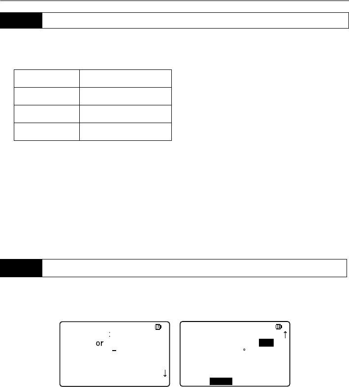
1. Press and hold {SFT} until the SFT Mode menu is
displayed. Select "Motor menu" from the second
page and press {I}.
2. Select Turning command.
• "Turn" - Series 230RM begins Turning directly
towards the RC controller.
• "Turn right" - Series 230RM begins Turning in a
clockwise (right) direction (from the point of view
of the operation panel).
• "Turn left" - Series 230RM begins Turning in a
counterclockwise (left) direction (from the point
of view of the operation panel).
3. To cancel Turning, press [STOP] during
operation.
7.5 Performing Turning from the Series 230RM SFT Mode
.Aiming
7. H angle set
8. Data view
9. Meas
Motor menu
EDIT
SFT menu
. Tilt
1. Search
2. Face change
3. Rotation
4. Laser-pointer: Off
SFT menu
5.Turn
6.Turn right
7.Turn left
"Turn left" "Turn right"
7. APPENDED SETTINGS FOR THE SERIES 230RM
32
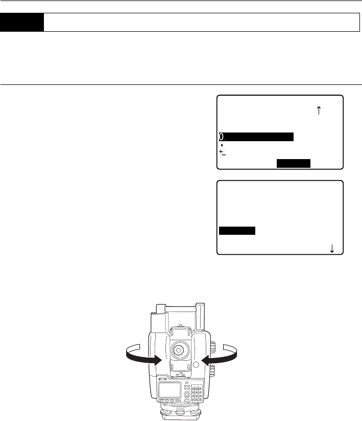
It is possible to allocate softkeys to the [RC], [RC →], [←RC] functions.
C For allocating softkey functions, see Series 230RM Operator’s Manual
The allocated softkeys are displayed in each measurement menu.
•Press [RC] and the Series 230RM begins Turning directly towards the RC controller.
•Press [←RC] and the Series 230RM begins Turning in a counterclockwise (left) direction (from the
point of view of the operation panel).
• Press [RC →] and the Series 230RM begins Turning in a clockwise (right) direction (from the point
of view of the operation panel).
7.6 Allocating Softkey Functions
[ ]
RC
Meas./Sdist PC -30
ppm 0
DIST
P1
RC
ZA 89 57’42"
HAR 359 01’20"
RC
S 15.120m
[←RC] [RC →]

33
7. APPENDED SETTINGS FOR THE SERIES 230RM
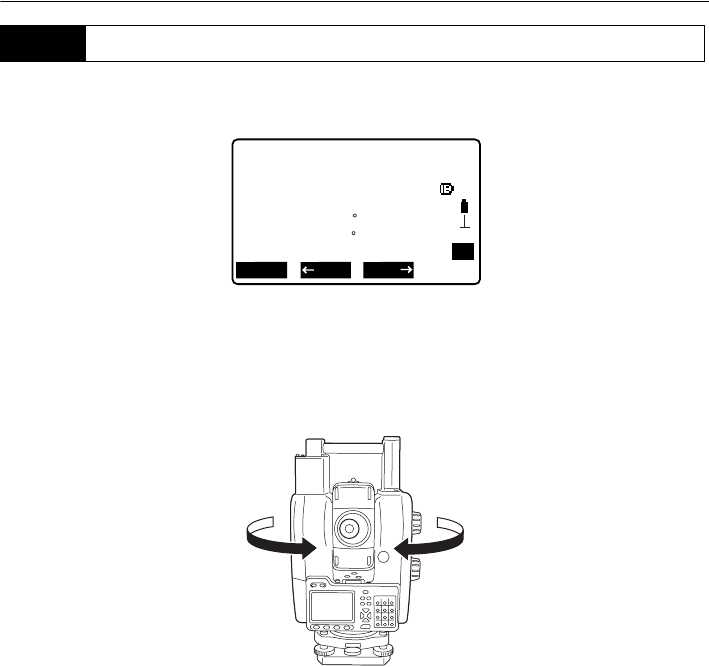
When Turning fails to detect the prism, an error occurs.
When the laser beam from the RC controller is reflected off an unrelated object the Series 230RM
completes Turning operation pointing at the object instead of the RC controller. When this happens,
press [CONT] to nullify the current measurement position and continue Turning operation.
For other softkeys, see "7.6 Allocating Softkey Functions"
Remotocatcher Communication err !!
Communication between the Series 230RM and RC controller has failed.
Check the status (communications setup, power supply, cable connections etc.) of the RC
controller, wireless modem and cables.
Motor error E592
Motor error E593
A hardware error has occurred with the RC controller.
Switch the power to the RC controller OFF and ON to correct the problem.
If the error reoccurs after restart, contact your Sokkia agent.
7.7 Turning Error
7.8 Error Messages
34
8. BASIC OPERATION
This section explains basic operation of the RC controller.
Mount the charged battery (BDC46B). When the remaining battery power becomes low, the ●
POWER Flashes.
CTypes of power source: "12.3 Power Supply System"
G
• Remove the battery when the instrument is not being used.
• Before removing the battery, turn off the power to the instrument. If the battery is removed while
the power is switched on, a warm boot occurs.
• When installing/removing the battery, make sure that moisture or dust particles do not come in
contact with the inside of the instrument.
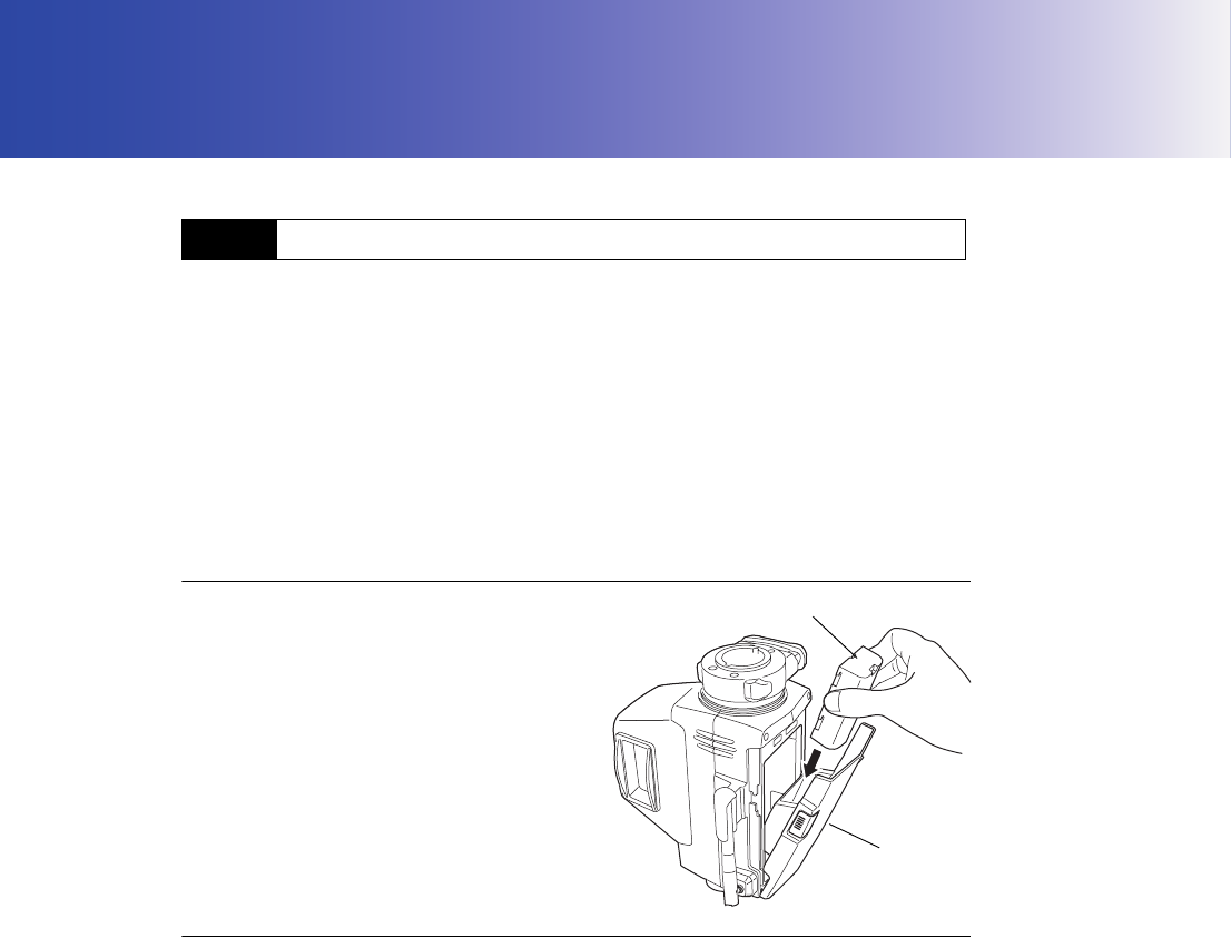
XPROCEDURE Mounting the battery
1. Slide down the catches on the battery cover to
open.
2. Insert the battery in the direction of the arrow
printed on the side.
3. Close the battery cover. A click is heard when
the cover is secure.
XPROCEDURE Removing the battery
1. Slide down the catches on the battery cover to
open.
2. Retract the battery.
3. Close the battery cover. A click is heard when
the cover is secure.
8.1 Using the Battery
Battery
B
attery
cover
35
8. BASIC OPERATION
The RC controller is operated using the buttons on the control panel.
8.2.1 Power ON/OFF
Press the POWER button to switch ON the RC controller. The ●POWER is Lit.
Press and hold the POWER button to switch OFF the RC controller. An audio tone sounds twice
and ●POWER Flashes before an audio tone sounds and the RC controller switches OFF.
8.2.2 Setting Distance Mode
The FAR button is used to set the Distance Mode depending on the distance between the total
station and the RC controller.
Pressing the FAR button switches the ●FAR from Lit to Off and vice versa.
Lit: Far Mode
Off: Standard Mode
Set to Far Mode when the distance between the total station and the RC controller is over 100m
(normal atmospheric conditions)/150m(good atmospheric conditions).
& Atmospheric conditions
• Normal: slight haze, visibility about 20 km, sunny periods, weak scintillation.
• Good: no haze, visibility about 40 km, overcast, no scintillation.
G
• Set to Standard Mode ( ●FAR is Off) when the total station and RC controller are close.
• Using Far Mode ( ●FAR is Lit) when the total station and RC controller are close could result in the
emitted laser beam being reflected off nearby objects. If this happens the total station will complete
Turning pointing to the object instead of the RC controller.
• Set to Far Mode ( ●FAR is Lit) even when the distance between the total station and the RC
controller is 100m or less if the height difference is large.
• Far Mode depletes battery power at a greater rate than Standard Mode.
The FAR button cannot be pressed while the total station is Turning.
8.2 Button Operations
8. BASIC OPERATION
36
8.2.3 Starting Turning Operation
Press the SEARCH button to start Turning operation.
•● SEARCH Flashes when the total station is currently performing Turning operation.
• When Turning operation is complete, an audio tone sounds and ● SEARCH remains Lit for approx.
2 seconds.
• Press the SEARCH button during operation to stop Turning.
• If the total station fails to detect the prism, a long audio tone sounds and ● SEARCH Flashes
quickly for approx. 2 seconds to indicate that an error has occurred.
• When the laser beam from the RC controller is reflected off a unrelated object the total station
completes Turning operation pointing at this object instead of the RC controller. When this happens,
press and hold the SEARCH button to nullify the current measurement position and continue
Turning operation.
37
8. BASIC OPERATION
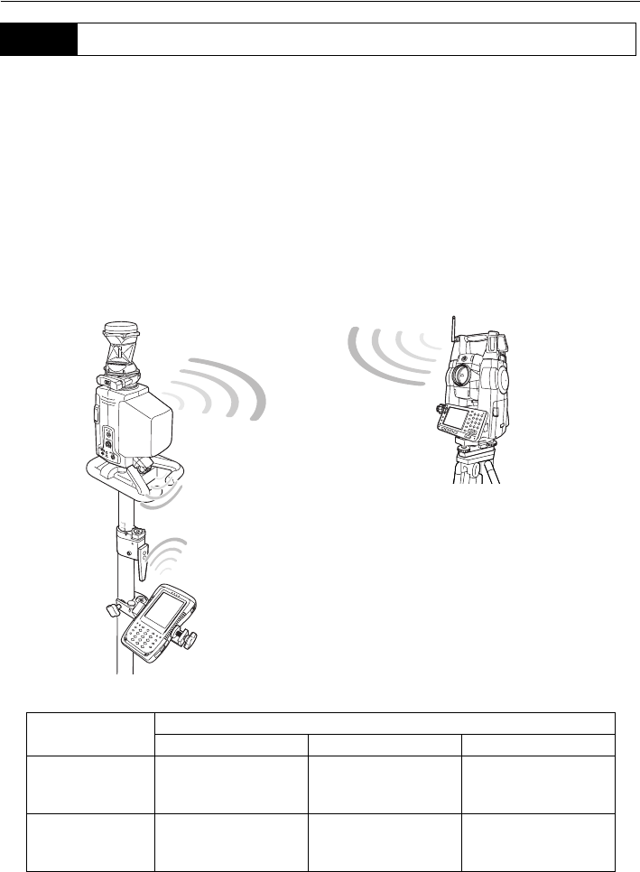
The Bluetooth wireless modem incorporated in the RC controller allows simultaneous communication
between the RC controller and both the total station and data collector. COM1 is for long-range (line-
of-sight distance up to 300m) communication with the total station. COM2 is for communication with
data collectors.
& Bluetooth connections
Communication between a pair of Bluetooth devices requires one device to be set as the "Master"
and the other as the "Slave". To initiate connections from the SRX/NET side, set the SRX/NET as
the "Master" device. To initiate connections from the paired device side, set the SRX/NET as the
"Slave" device. The factory setting for the SRX/NET is "Slave".
Bluetooth connections are as follows:
COM1: Total station (Slave) - RC controller (Master)
COM2: Data collector (Master) - RC controller (Slave)
8.3 Communication Status
Port Control panel status
Lit Off Flashing
COM1 (total
station) Comm OK
Serial communication
setup/connection in
progress
Searching for total
station
COM2 (data
collector) Comm OK
Serial communication
setup/connection in
progress
Data collector is
searching for RC
controller
COM2
COM1
Handle: RC-TS3
38
9. RC CONTROLLER SETTINGS
G
Press and hold the POWER button . Check that the power is OFF before setting the RC controller
settings.
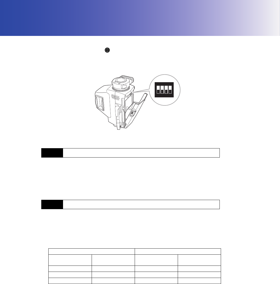
Open the battery cover to reveal the battery housing inside which there is a dip switch.
Dip switch 1 is used to activate/deactivate the auto power-off function.
Dip switch 1: OFF - Auto power-off function activated.
To save power, power to the RC controller is automatically cut off if it is not operated, no
communication is performed for 30 minutes.
The auto power-off function was activated (dip switch 1: OFF) when your RC controller was shipped
from the factory.
Dip switch 3 sets the mode for communication between the RC controller and the total station. Dip
switch 4 sets the mode for communication between the RC controller and the data collector.
Dip switch 3/Dip switch 4 ON: Serial communication mode
Dip switch 3/Dip switch 4 OFF: Bluetooth wireless communication mode
Set Dip switch 3 to ON when using a wireless modem with an SRX/NET (with RC-TS3A)/Series
230RM instrument.
9.1 Setting Auto Power-off
9.2 Setting Communication Mode
Switch setting Communication mode
Dip switch 3 Dip switch 4
COM1 (total station)
COM2 (data
collector)
OFF OFF Bluetooth Bluetooth
ON OFF Serial Bluetooth
OFF ON Bluetooth Serial
44 33 22 11
ON
39
9. RC CONTROLLER SETTINGS
$
• The above Bluetooth settings were completed at the factory. To change these settings contact your
Sokkia agent.
• When the usable range for Bluetooth communication is exceeded or communication failures occur
regularly, the Communication Mode can be set to Serial and communication performed by
connecting the wireless modem with the relevant cable. For details, contact your Sokkia agent.
Dip switch 2 is used to set the baud rate for serial communication mode.
The RC controller communication setup is as follows.
Dip switch 2: ON - Baud rate will be set to 9600 bps.
Dip switch 2: OFF - Baud rate will be set to 1200 bps.
The baud rate was set to 1200 bps (dip switch 2: OFF) when your RC controller was shipped from the
factory.
G
To change the communication settings to values other than those shown above, contact your
Sokkia agent.
The onboard electronic compass was calibrated before being shipped from the factory. A function
within the compass will automatically perform any necessary calibration in response to changes in the
magnetic field. Although this function by itself is sufficient in normal situations, when the RC controller
becomes highly magnetized, manual calibration is necessary.
G
• When the power is ON, automatic calibration is performed to adjust for changes in temperature and
magnetic field. When transporting the RC controller, with the power still ON, using modes of
transport such as cars or trains which contain a large amount of magnetic substance (iron, magnets
etc.), this function will calibrate for the magnetic field of said car or train. As a result, the direction in
which the RC controller instructs a rotation in subsequent surveying tasks may not be correct.
Always turn the power OFF when transporting.
• Manually calibrate the compass in the event that the RC controller has been transported with the
power still ON and the resulting calibration inaccuracy persists.
9.3 Communication Setup for the RC Controller
Baud rate 1200 bps or 9600 bps
Data bits 8
Stop bit 1
Parity Non parity
9.4 Calibrating the Electronic Compass

9. RC CONTROLLER SETTINGS
40
• The ideal location for performing manual calibration would be an open area clear of any objects.
Failing that, make sure that the surrounding area (i.e. several meters around the instrument
including ground level) is clear of metallic objects (desks, steel frames, etc.) or devices containing
magnets.
• Hold the RC controller on the pole at a height of at least 1m.
• Avoid physical contact with metallic objects (cellular phones, tape measures, etc.) or magnetic
objects (such as magnetic necklaces) while performing manual calibration.
XPROCEDURE Checking whether manual calibration is necessary
1. Press the POWER button to switch ON
the RC controller. ● POWER is Lit.
If ●FAR and ●SEARCH flash and a rapid
error tone sounds repeatedly, relocate to a
position several meters away from metallic
objects (desks, steel frames, etc.) or devices
containing magnets before trying again.
If the audio tone continues to sound even after
changing location, manual calibration is
necessary.
2. When calibration is necessary, switch OFF
and proceed to "PROCEDURE Manually
calibrating the compass".
41
9. RC CONTROLLER SETTINGS
XPROCEDURE Manually calibrating the compass
1. Press the POWER button while pressing
the FAR button with the power switched
OFF. An audio tone sounds and the RC
controller is switched ON in calibration mode.
●FAR and ●SEARCH are Lit.
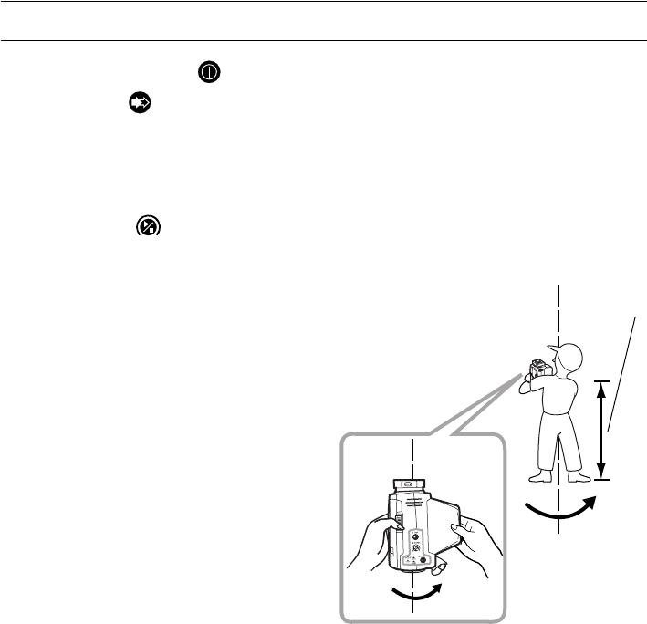
2. Hold the RC controller vertical and press the
SEARCH button .
●FAR flashes red and calibration starts.
3. Without moving the position of the RC
controller, rotate it 1.5 to 2 times in a horizontal
direction.
G
Rotate 1.5 to 2 times in approximately 10
seconds.
1m or above
9. RC CONTROLLER SETTINGS
42
4. After rotating, continue to hold the RC
controller vertical and press the SEARCH
button .
●SEARCH turns Off.
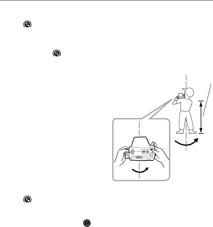
5. Hold the RC controller horizontal and press
the SEARCH button .
●FAR Flashes.
6. Without moving the position of the RC
controller, rotate it 1.5 to 2 times in a horizontal
direction.
7. After rotating, continue to hold the RC
controller horizontal and press the SEARCH
button .
8. ●FAR turns Off.
9. Push and hold the POWER button on the
RC controller to switch OFF. ●POWER turns
Off and calibration is complete.
1m or above

43
10. ERROR INDICATIONS
When an error occurs, the nature of the error is indicated by the condition of the LEDs on the RC
controller
LED Condition Error
●POWER Flashing Remaining battery power is low.
Replace the batteries.
C "8.1 Using the Battery"
3 long audio tones and the
●POWER Flashes then
power is cut off
No battery power remaining.
Replace the batteries.
C "8.1 Using the Battery"
Audio tone continues to
sound and the ●POWER
Flashes quickly/audio tone
sounds continuously for
approx. 10 seconds
The remaing battery power of the total
station is low or the total station has switched
OFF.
Check the power to the total station.
C Operator's Manual (Series SRX/
NET05/NET1)/Series 230RM
Operator’s Manual
●FAR/all LEDs Flashing
quickly
Hardware error.
Switch the power to the RC controller OFF
and ON again. If the error reoccurs after
restart, contact your Sokkia agent.
A long audio tone sounds
and ● SEARCH Flashes
quickly for approx. 2
seconds
Turning failure
C "11. TROUBLESHOOTING"
3 audio tones and the
●FAR/ ● SEARCH Flash
There are magnetic/metallic objects in the
vicinity. Retry at a distance greater than sev-
eral meters from such objects. If the audio
tone continues to sound even after changing
location, manual calibration is necessary.
C "9.4 Calibrating the Electronic Compass"

44
11. TROUBLESHOOTING
●Pressing the POWER button does not switch ON the power.
→Check that the battery has been inserted.
Replace the battery.
C "8.1 Using the Battery"
●The RC controller switches OFF without warning.
→Auto power-off function activated and the RC controller has not been operated for 30
minutes.
Deactivate this function if not needed.
C "9.1 Setting Auto Power-off"
●The total station does not perform Turning operation even when distance measure-
ment is executed.
→The Turning operation setting of the total station is deactivated.
Set the "Srch method" setting for the SRX/NET to "R.C.".
C "6.2 Settings for Auto Pointing and Auto Tracking"
Set the Search before Distance Measurement setting for the Series 230RM to "RC".
C "7.4 Setup for Search Before Distance Measurement"
→A connection has not been established with the total station.
Check that the communication settings for all connected devices are set to the same values.
Users with multiple RC controllers should make sure that the combinations of total stations, RC
controllers, and data collectors being used are correct.
C "7.3 Communication Setup"
Check that the wireless modem cable is correctly connected. Check the remaining battery power.
●Turning operation failure
→The beam detector cover is closed.
Close the beam detector cover.
C "7.1 Beam Detector"
→Both the laser projection port and the prism are not pointing in the direction of the total station.
Point the laser projection port and the prism towards the total station.
→The total station cannot receive the beam emitted from the RC controller as the amount of light is
too low.
Check that the Distance Mode setting is correct.
C "8.2.2 Setting Distance Mode"
→Turning operation has located the horizontal position but cannot find the vertical position.
Turning operation for the vertical position cannot be performed while the pole is tilted at an
angle.
Check that the pole is fixed in the correct position, vertically over the measurement point.
→Check that there are no obstacles between the beam detector of the total station and the
laser projection port of the RC controller/prism.
→Flat white surfaces in close proximity to the optical path between the total station beam
detector and RC controller laser projection port may reflect the emitted laser beam and
cause Turning operation failure. Have someone stand in front of such objects or otherwise
cover, such as with a dark-colored cloth.
→There is dust or dirt on the beam detector/laser projection port.
Dust off minute particles with the lens brush before carefully wiping with the cleaning cloth.

45
11. TROUBLESHOOTING
●Total station finishes Turning operation pointing in the wrong direction.
→The total station receives the emitted laser beam after it has been reflected off a highly-
reflective surface in the vicinity of the RC controller.
Continue Turning operation.
C "4.2 Measurement Flow"
C "6.3 Performing Turning from the SRX/NET"/"7.5 Performing Turning from the Series 230RM
SFT Mode"
●The signal for the data collector/wireless modem equipped with Bluetooth wireless technol-
ogy is weak.
→The wireless modem signal is poor because the modem is placed in a low position, close to
ground level.
Place the modem in as high a position as possible.
46
12. STANDARD EQUIPMENT AND OPTIONAL ACCESSORIES
G
• Place the instrument in its case in accordance with the layout plan on the inside of the carrying case.
• Place the data collector in its dedicated protective case before inserting into the carrying case.
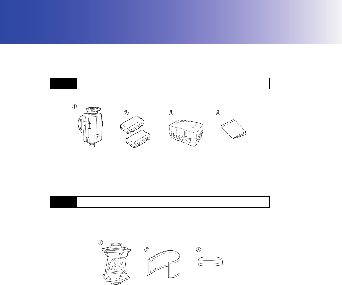
Please verify that all equipment is included.
For use with other prism types, contact your Sokkia agent.
360° Prism (ATP1)
12.1 Standard Equipment
12.2 Optional Accessories
1 RC-PR3 main unit . . . . . . . . . . . . . . . . 1
2 Battery (BDC46B) . . . . . . . . . . . . . . . . 2
3 Carrying case (SC220/220A) . . . . . . . 1
4 On-demand Remote Control System . .
Manual . . . . . . . . . . . . . . . . . . . . . . . . 1
1 360° Prism (ATP1) . . . . . . . . . . . . . . . 1
2 Protective cover . . . . . . . . . . . . . . . . . 1
3 Cap . . . . . . . . . . . . . . . . . . . . . . . . . . . 1
47
12. STANDARD EQUIPMENT AND OPTIONAL ACCESSORIES
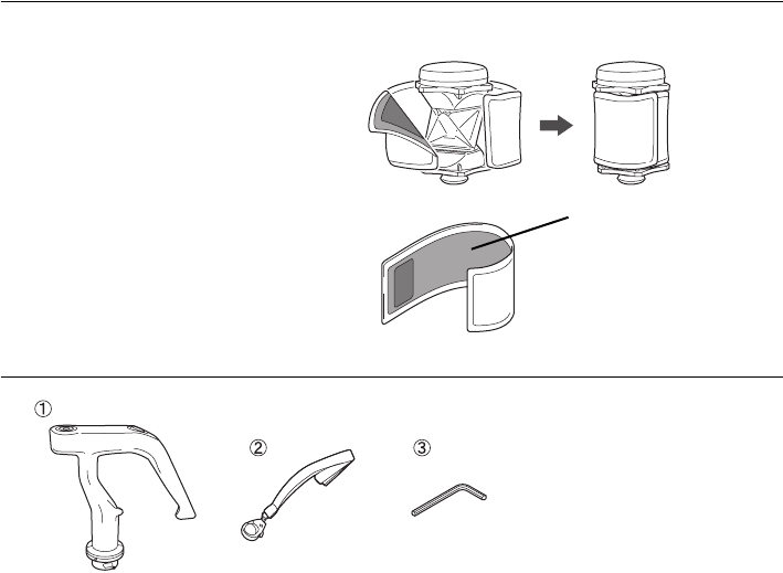
●Protective cover
Attach the protective cover when the
prism is not being used to protect the
prism surface from dirt and damage.
$
• The inner (light grey) section can be
used as a cleaning cloth to wipe the
surface of the prism.
Trigger Grip (RC-PRH3)
Inner: light grey (cleaning
cloth section)
1 Trigger grip . . . . . . . . . . . . . . . . . . . . . 1
2 Strap . . . . . . . . . . . . . . . . . . . . . . . . . . 1
3 Adjusting pin . . . . . . . . . . . . . . . . . . . . 1
12. STANDARD EQUIPMENT AND OPTIONAL ACCESSORIES
48
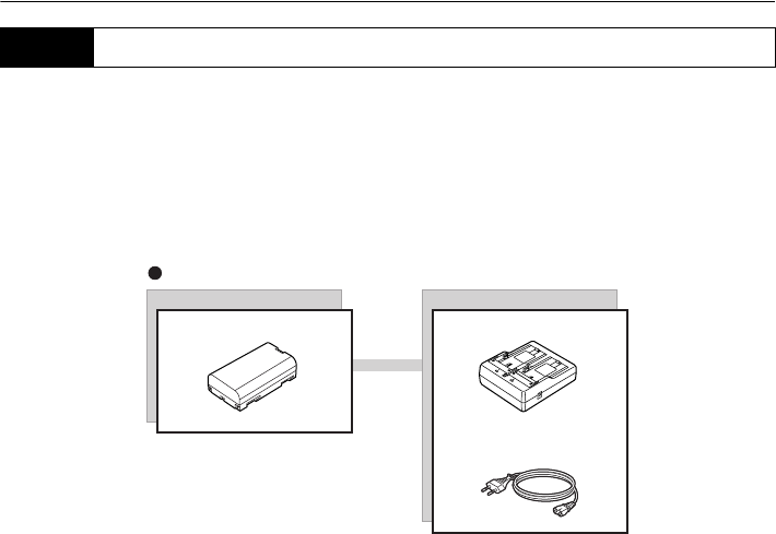
Operate your RC-PR3 with the following combinations of power equipment.
G
• Never use any combination other than those indicated below. If you do, the instrument could be
damaged.
Those indicated by * are standard accessories. Others are optional accessories (sold separately)
The power cable shown here is EDC113A
12.3 Power Supply System
Battery
BDC46B* CDC68
EDC113A/113B/113C
(100 V AC)
Charger
Battery

49
13. SPECIFICATIONS
Whole System Specifications
Range: (Slope distance between instrument and measuring point)
(Using Sokkia's reflective prism target during normal atmospheric
conditions*1)
Standard Mode: 2*2 to 100m*3
Far Mode: 2*2 to 250m*4/300m*3
Operating time*5: About 15 sec. Up to finishing distance measurement (Rapid (single))
Operating range of function for automatically determining rotation direction:
Magnetic inclination is 80° or less and horizontal component is
more than 10µT*6
Data collector: Sokkia total station/3-D station-compatible product*6
Control panel (keyboard) 3 Keys
Indicator 6 LED
Auto power-off Yes (powers OFF if not used for 30 min.)/No
Audio tone Yes
Operating temperature -20 to 50°C
Storage temperature range -30 to 70°C
Water resistance IP55 (IEC 60529:2001)
Size 99 (L) X 124 (W) X 196 (H) mm
Weight About 1.1 kg (with BDC46B)
*1: Normal: Slight haze, visibility about 20 km, sunny periods, weak scintillation.
Depends on the wireless modem used.
*2: Possible to use 1.8m (horizontal distance), height of instrument point and measurement point
is almost the same, instrument height is 1.5m, and prism height is 0.05m.
*3: About 20m height difference between instrument and RC controller laser projection port.
*4: About 40m height difference between instrument and RC controller laser projection port.
*5: Time taken between the start of the search and the obtaining of distance measurement results
after the completion of Auto Pointing. Normal atmospheric conditions, instrument Turning
horizontally 90°, 100m distance between instrument and measuring point.
Depends on the conditions and wireless modem used.
*6: For details, contact your Sokkia agent.
RC Controller (RC-PR3)
Laser Projection Port
Signal source Laser diode (IEC60825-1 Amd. 2: 2001/FDA CDRH 21 CFR Part
1040.10 and 1040.11 (Complies with FDA performance standards for
laser products except for deviations pursuant to Laser Notice No.50,
dated July 26, 2001.))
Wavelength: 785nm
Beam projection area
Horizontal direction: -10 to 10°
Angle of elevation: More than 40°
Angle of depression: More than 30°
Rotation direction detector
Direction detector magnetic compass sensor (geomagnetic
measurement method)

13. SPECIFICATIONS
50
With automatic/manual calibration function
Measurement resolution ±1°
Wireless modem
Wireless communication
Transmission method: FHSS (Bluetooth Specification Ver.1.2 compatible, TELEC-
compliant)
Modulation: GFSK
Frequency band: 2,402 to 2,480GHz
Bluetooth profile SPP, DUN
BT Qualification ID:
Module hardware: B012647
Module software: B011340
Power class Class 1
Antenna*7 External antenna
Usable range*7: 200m (No obstacles, few vehicles or sources of radio emissions/
interference in the near vicinity of the instrument, no rain)
300m (No obstacles, few vehicles or sources of radio emissions/
interference in the vicinity of the instrument, no rain)
Authentication Yes/No (selectable)
Serial communication port*6
Data input/output Computer/data collector
Interface RS232C compatible
Communication settings*8 (*: factory settings)
Baud rate: 1200*/2400/4800/9600/19200/38400
Data bits: 7/8* bits
Stop bit: 1*/2 bits
Parity: Not set*/Odd/Even
Compatible wireless modem
Interface: Asynchronous serial RS232C compatible
Conditions: Possible to set up same as communication setting
Through Mode provided
Power supply: Self-Supply
*7: COM1: For communication with total station COM2: For communication with data collector
*8: To change the communication settings to values other than those shown here, contact your
Sokkia agent.

51
13. SPECIFICATIONS
Power Supply (BDC46B)
Battery
Type: Rechargeable Li-ion battery BDC46B
Working duration*9 (25°C)
Standard Mode: Over 14 hours (RC controller used once for 10 seconds per minute)
Far Mode: Over 13 hours (RC controller used once for 10 seconds per minute)
Charging time at 25 °C: about 2.5 hours (using CDC68)
*9: Repeat Turning with the instrument turned 90° and distance measurement performed in Rapid
measurement (single) every 1 minute.
Trigger grip (RC-PRH3)
Sensitivity of levels 35’/2mm
Trigger key Yes
Size 37 (W) X 127 (D) X 137 (H) mm
Weight About 130g
360° Prism (ATP1)
Measuring range (Using SRX/NET, angles of elevation and inclination both less than
10°)
EDM 1.3 to 1000m*10
Auto Tracking 2 to 500m*10
Auto Pointing 2 to 600m*10
Prism constant -7mm
3D positioning accuracy (standard deviation)
3mm (Angles of elevation and inclination both less than 20°)
Prism height 37mm (from mounting face (flange face) when attached to RC-PR3)
Operating temperature -20 to 50°C
Storage temperature range -30 to 70°C
Size 70 (W) X 104 (H) mm (with cap)
Weight 265g (with cap)
*10: No haze, visibility over 20 km, slightly overcast (less than 30000 lx), no scintillation.
SET instrument compatible with On-demand Remote Control System (Series
230RM)
Beam Detector
Maximum Range (Vertical angle):
-40° to +30° (Horizontal: 0°)
Power supply
Working duration*11 (20°C)
Using BDC45: about 4 hours (about 240 times use)
Using BDC7 (optional accessory): about 7.5 hours (about 450 times
use)

13. SPECIFICATIONS
52
*11: Repeat Turning with the instrument turned 90° and distance measurement performed in Rapid
measurement (single) every 1 minute.
General
Size 202 (W) X 165 (D) X 383 (H) mm (with handle)
Weight (with handle and battery) 3230RM/4230RM: About 7.6kg
53
14. EXPLANATION
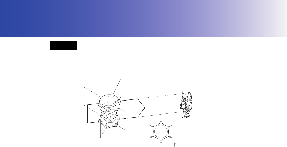
Sighting can be more accurately performed by facing the 360° Prism toward the total station. The 360°
Prism should be set up so that a pair of diametrically-opposed hexagonal points on its rubber flanges
are aligned with the sighting direction of the total station (see the diagram below).
14.1 High Accuracy with the 360° Prism
: Hexagonal points

54
15. REGULATIONS
Users must ensure that their instrument is compliant with the relevant regulations and legal restrictions
in place in the country of use.
For users in the US
WARNING: Changes or modifications to this unit not expressly approved by the party responsible for
compliance could void the user's authority to operate the equipment.
NOTE: This equipment has been tested and found to comply with the limits for a Class A digital device
pursuant to Part 15 of the FCC Rules. These limits are designed to provide reasonable protection
against harmful inter-ference when the equipment is operated in a commercial environment. This
equipment generates, uses, and can radiate radio frequency energy and, if not installed and used in
accordance with the instruction manual, may cause harmful interference to radio communications.
Operation of this equipment in a residential area is likely to cause harmful interference in which case
the user will be required to correct the interference at his own expense.
This transmitter must not be co-located or operated in conjunction with any other antenna or
transmitter.
This equipment complies with FCC radiation exposure limits set forth for uncontrolled equipment and
meets the FCC radio frequency (RF) Exposure Guidelines in Supplement C to OET65. This equipment
should be installed and operated with at least 20cm and more between the radiator and person’s body
(excluding extremeties: hands, wrists, feet and ankles).
For users in Canada
This Class A digital apparatus meets all requirements of Canadian Interference-Causing Equipment
Regulations.
Cet appareil numérique de la Class A respecte toutes les exigences du Règlement sur le matériel
brouilleur du Canada.
This class A digital apparatus complies with Canadian ICES-003.
Cet appareil numerique de la classe A est conforme a la norme NMB-003 du Canada.
Operation is subject to the following two conditions: (1) this device may not cause interference, and
(2) this device must accept any interference, including interference that may cause undesired
operation of this device.
This equipment complies with IC radiation exposure limits set forth for uncontrolled equipment and
meets RSS-102 of the IC radio frequency (RF) Exposure rules. This equipment should be installed
and operated with at least 20cm and more between the radiator and person’s body (excluding
extremeties: hands, wrists, feet and ankles).
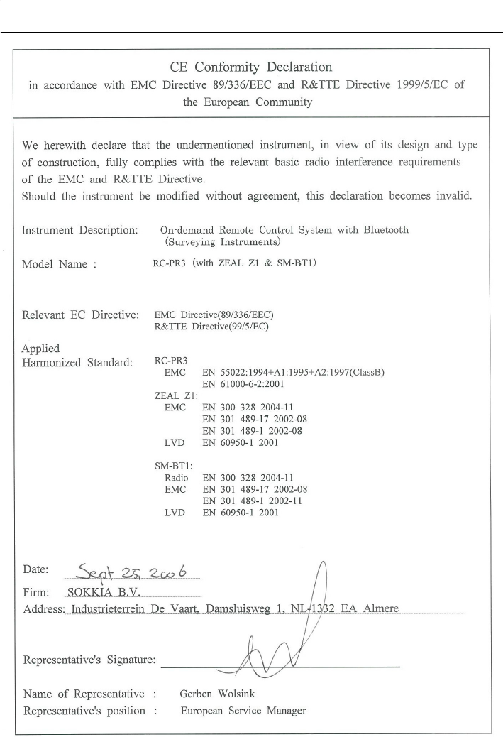
55
15. REGULATIONS
For users in the European Economic Area (EEA)
15. REGULATIONS
56
RC-PR3
57
15. REGULATIONS
For users in Mexico
Este equipo opera a titulo secundario, consecuentemente, debe aceptar interferencias perjudiciales
incluyendo equipos de la misma clase y puede no causar interferencias a sistemas operando a titulo
primario.
COFETEL + RCPSOSM07-290
COFETEL + RCPSOZE06-471
15. REGULATIONS
58
For users in the People’s Republic of China
For users in the Republic of Korea
ᷛᯢ䰘ӊЁ᠔㾘ᅮⱘᡔᴃᣛᷛՓ⫼㣗ೈˈ䇈ᯢ᠔᳝ࠊǃ䇗ᭈঞᓔ݇ㄝ
Փ⫼ᮍ⊩˗
ع
Փ⫼乥⥛
㧦2.4 - 2.4835 GHz
ع䷘㟗⏷⚠戟⺓┮䘖(EIRP)᧶
⮸兎⬭䥙᧸10dBi 㢅᧶ื100 mW 㒥ื20 dBm
ع㦏⮶┮䘖廀⹕ㄵ᧶
⮸兎⬭䥙᧸10dBi 㢅᧶ื20 dBm / MHz(EIRP)
ع戌欠⹈棟᧶20 ppm
ϡᕫ᪙㞾ᬍথᇘ乥⥛ǃࡴথᇘࡳ⥛ࣙᣀ乱ࡴ㺙ᇘ乥ࡳ⥛ᬒ఼ˈ
ϡᕫ᪙㞾㒓ᬍ⫼݊ᅗথᇘ㒓˗
Փ⫼ᯊϡᕫᇍ⾡ড়⊩ⱘ᮴㒓⬉䗮ֵϮࡵѻ⫳᳝ᆇᑆᡄ˗ϔᮺথ⦄᳝ᑆᡄ
⦄䈵ᯊˈᑨゟेذℶՓ⫼ˈᑊ䞛পᮑ⍜䰸ᑆᡄৢᮍৃ㒻㓁Փ⫼˗
Փ⫼ᖂࡳ⥛᮴㒓⬉䆒ˈᖙ乏ᖡফ⾡᮴㒓⬉ϮࡵⱘᑆᡄᎹϮǃ⾥ᄺঞ
ए⭫ᑨ⫼䆒ⱘ䕤ᇘᑆᡄ˗
ϡᕫ亲ᴎᴎഎ䰘䖥Փ⫼DŽ
A12-RC1(A)
A12-SM-BT1
A12-Z1
MADE IN JAPAN
59
15. REGULATIONS
For users in Singapore
For users in Taiwan
For users in the United Arab Emirates
Approved by TRA
Complies with
IDA Standards
DB101547

MEMO
60
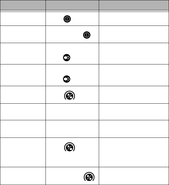
Button Operations
Operation Button Operation Indication
POWER ON Press once ●POWER is Lit
POWER OFF Press and hold ●POWER Flashes then turns
Off
Far Mode
When ●FAR is Off,
press once
●FAR is Lit
Standard Mode
When ●FAR is Lit,
press once
●FAR is Off
Start Turning Press once
Turning in
operation ●SEARCH Flashes
Turning complete ●SEARCH is Lit for 2
seconds
Cancel Turning
Press once
while Turning in
operation
●SEARCH is Off
Continue Turning Press and hold ●SEARCH Flashes

©2006 SOKKIA CO., LTD.
JAPAN