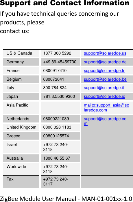
SolarEdge Technologies SEZB Zigbee Module for communication between products User Manual ZigBee Module MAN 01 001xx 1 0

SolarEdge Technologies Ltd Zigbee Module for communication between products ZigBee Module MAN 01 001xx 1 0

User manual

 ZigBee Module User Manual - MAN-01-001xx-1.0 Disclaimers Important Notice Copyright © SolarEdge Inc. All rights reserved. No part of this document may be reproduced, stored in a retrieval system, or transmitted, in any form or by any means, electronic, mechanical, photographic, magnetic, or otherwise, without the prior written permission of SolarEdge Inc. This document is solely for the use of SolarEdge customers and employees. The material furnished in this document is believed to be accurate and reliable. However, SolarEdge assumes no responsibility for the use of this material. SolarEdge reserves the right to make changes to the material at any time and without notice. You may refer to the SolarEdge web site (www.solaredge.com) for the most updated version.
 ZigBee Module User Manual - MAN-01-001xx-1.0 All company and brand products and service names are trademarks or registered trademarks of their respective holders. Patent marking notice: http://www.solaredge.com/groups/patent The general terms and conditions of purchase of SolarEdge products shall apply. The content of these documents is continually reviewed and amended, where necessary. However, discrepancies cannot be excluded. No guarantee is made for the completeness of these documents.
 ZigBee Module User Manual - MAN-01-001xx-1.0
 ZigBee Module User Manual - MAN-01-001xx-1.0 Table of Contents Disclaimers ..........................................................................2 Important Notice ............................................................ 2 Table of Contents ................................................................5 About This Manual ..............................................................6 Support and Contact Information ...................................... 13 Chapter 1: Introducing the ZigBee Communication ............ 15 Overview ....................................................................... 15 Package Contents ......................................................... 15 Installation Procedure .................................................. 15 Chapter 2: Technical information of the SolarEdge ZigBee . 17 General ......................................................................... 17 Module Features ........................................................... 17 SolarEdge Supported Productse ................................... 18 Mechanical Information ............................................... 18 Chapter 3: Installing the ZigBee Module and Antenna ....... 19 Installing the Antenna and Cable .................................. 19 Mounting the Module in the Inverter ........................... 23 Appendix A: Configuring ZigBee Communication ............... 27 Appendix B: Technical Specifications ................................. 32 Appendix C: Agency Certifications ..................................... 35
 ZigBee Module User Manual - MAN-01-001xx-1.0 About This Manual This user manual is intended for Photovoltaic (PV) system owners, installers, technicians, maintainers, and integrators who use the SolarEdge power harvesting system. This manual describes how to install and set up ZigBee™ communication in a SolarEdge device (inverter or Safety and Monitoring Interface – SMI). The manual instructions and graphics refer to the inverter; however apply to SMI as well.  This guide assumes that the SolarEdge power harvesting system is already installed and commissioned. For additional information about how to install and commission the SolarEdge power harvesting system, refer to the relevant installation guide.
 ZigBee Module User Manual - MAN-01-001xx-1.0 The guide includes the following chapters:  Chapter 1: Introducing the ZigBee Communication, page 11, describes the SolarEdge ZigBee slave module functionality and connection.  Chapter 2: Technical information of the SolarEdge ZigBee  General The SolarEdge ZigBee Module (SE ZB Module) is a Zigbee Module, enabling Zigbee communication between SolarEdge products – Inverter, Gateway, Home Gateway etc. The Main usage of the SE ZB is to create a ZigBee link between user's products, enabling the user to connect to all ZigBee products via one link, and transfer the data to the Server. By creating a ZigBee link, the user can spare the use of communication cable between his products, enabling easy installation in any place.
 ZigBee Module User Manual - MAN-01-001xx-1.0 Module Features  Point-to-point connection  Point-to-Multipoint connection  Indoor\Outdoor communication   AT Command control  No configuration needed SolarEdge Supported Productse  SolarEdge Portia (all versions)  SolarEdge Gateway (all versions)  SolarEdge Home Gateway (all versions)  Mechanical Information
 ZigBee Module User Manual - MAN-01-001xx-1.0  Size (W) : 26.2 mm  Size (L) : 50 mm  Size (H) : 10.2 mm   Chapter 3: Installing the ZigBee Module and Antenna, page 13, describes the module electrical specifications, pinout description, supported devices and mechanical information.  Chapter 2: Technical information of the SolarEdge ZigBee General The SolarEdge ZigBee Module (SE ZB Module) is a Zigbee Module, enabling Zigbee communication between SolarEdge products – Inverter, Gateway, Home Gateway etc. The Main usage of the SE ZB is to create a ZigBee link between user's products, enabling the user to connect to all ZigBee products via one link, and transfer the data to the Server. By creating a ZigBee link, the user can spare the use of communication cable between
 ZigBee Module User Manual - MAN-01-001xx-1.0 his products, enabling easy installation in any place.  Module Features  Point-to-point connection  Point-to-Multipoint connection  Indoor\Outdoor communication   AT Command control  No configuration needed SolarEdge Supported Productse  SolarEdge Portia (all versions)  SolarEdge Gateway (all versions)  SolarEdge Home Gateway (all versions)
 ZigBee Module User Manual - MAN-01-001xx-1.0 Mechanical Information    Size (W) : 26.2 mm  Size (L) : 50 mm  Size (H) : 10.2 mm   Chapter 3: Installing the ZigBee Module and Antenna, page 15, describes how to mount, connect and verify the connection of the ZigBee slave module.  Appendix A: Configuring ZigBee Communication, page 23, describes how to set up the ZigBee communication type in the inverter, if necessary.
 ZigBee Module User Manual - MAN-01-001xx-1.0  Appendix B: Technical Specifications page 28, provides the electrical and mechanical specifications of the SolarEdge ZigBee slave module.  Appendix C: Agency Certifications page 31, Provides all relevant module approvals. For further information, datasheets and the most up-to-date certifications for various products in different countries, please visit the SolarEdge website: www.solaredge.com
 ZigBee Module User Manual - MAN-01-001xx-1.0 Support and Contact Information If you have technical queries concerning our products, please  contact us:  US & Canada 1877 360 5292 support@solaredge.us Germany +49 89-45459730  support@solaredge.de France 0800917410 support@solaredge.fr Belgium 080073041 support@solaredge.be Italy 800 784 824 support@solaredge.it Japan +81.3.5530.9360 support@solaredge.jp Asia Pacific   mailto:support_asia@solaredge.com Netherlands 08000221089 support@solaredge.com United Kingdom  0800 028 1183 Greece 00800125574 Israel +972 73 240-3118 Australia 1800 46 55 67 Worldwide +972 73 240-3118  Fax +972 73 240-3117
 ZigBee Module User Manual - MAN-01-001xx-1.0 Before contacting SolarEdge, ensure you have the product serial number as appears on its label.
 ZigBee Module User Manual - MAN-01-001xx-1.0 Chapter 1: Introducing the ZigBee Communication  Overview ZigBee is a technology that enables wireless connection between several SolarEdge devices. Up to 32 devices may be inter-connected, in a master-slave configuration. One device is the master (either by having a master ZigBee module pre-installed, or by installing the SolarEdge ZigBee master kit (sold separately). All the other modules act as slaves. Package Contents  ZigBee slave module  Antenna   Mounting clip with RF cable  This installation guide Installation Procedure The following illustrates the steps required for the home gateway installation:
 ZigBee Module User Manual - MAN-01-001xx-1.0   Page 17   Refer to the Home Gateway or ZigBee master kit manuals   Refer to Home Gateway or ZigBee master kit manuals Device discoveryInstall  the home gateway or a ZigBee master on one of the devices Install a slave module in all slave devices
 ZigBee Module User Manual - MAN-01-001xx-1.0 Chapter 2: Technical information of the SolarEdge ZigBee General The SolarEdge ZigBee Module (SE ZB Module) is a Zigbee Module, enabling Zigbee communication between SolarEdge products – Inverter, Gateway, Home Gateway etc. The Main usage of the SE ZB is to create a ZigBee link between user's products, enabling the user to connect to all ZigBee products via one link, and transfer the data to the Server. By creating a ZigBee link, the user can spare the use of communication cable between his products, enabling easy installation in any place.  Module Features  Point-to-point connection  Point-to-Multipoint connection  Indoor\Outdoor communication   AT Command control  No configuration needed
 ZigBee Module User Manual - MAN-01-001xx-1.0 SolarEdge Supported Productse  SolarEdge Portia (all versions)  SolarEdge Gateway (all versions)  SolarEdge Home Gateway (all versions)  Mechanical Information    Size (W) : 26.2 mm  Size (L) : 50 mm  Size (H) : 10.2 mm
 ZigBee Module User Manual - MAN-01-001xx-1.0 Chapter 3: Installing the ZigBee Module and Antenna Install a slave module in all the devices that will communicate with the master ZigBee device (e.g. home gateway).  Installing the Antenna and Cable  1 Connect the antenna to the mounting clip.  Figure 1: Connecting the antenna to the mounting clip 2 Attach the mounting clip with the antenna vertically to the top of the inverter. You may attach the clip to the heat sink fins or the inverter side.
 ZigBee Module User Manual - MAN-01-001xx-1.0   Figure 2: Antenna mounted on the inverter For other SolarEdge devices, or if mounting the antenna not on the inverter top, install the clip on the wall using two screws (not supplied). The antenna must be vertical and far from metal surfaces (including the inverter side). 3 Route the antenna cable along the inner fins or the inverter side, in the bracket. Make sure the cable is not hanging loose outside the inverter enclosure. Single phase inverter           Three phase inverter
 ZigBee Module User Manual - MAN-01-001xx-1.0  Figure 3: Routing the antenna cable (Three phase inverter) 4 Disconnect the AC power to the inverter and wait 5 minutes. 5 Open the inverter cover as described in its manual. 6 Open the gland numbered 1 at the bottom of the SolarEdge inverter.  Figure 4: Inverter sealing glands
 ZigBee Module User Manual - MAN-01-001xx-1.0 7 Remove the rubber seal from the gland and insert the RF cable through the gland cover and the opened connection of the inverter.  8 Push the cable into the cut opening of the rubber seal.  Figure 5: Rubber seal  9 Insert the rubber seal with the cable into to the gland body and reconnect the gland to the inverter. Tighten the sealing gland.  10 Insert the excess of cable length into the inverter until the cable can be tightly attached to the inverter side.    Cut opening
 ZigBee Module User Manual - MAN-01-001xx-1.0 Mounting the Module in the Inverter 1 Connect the ZigBee slave module in its place on the communication board, as shown in Figure 6.  Follow these guidelines:   Use the marking on the communication board to plug in the ZigBee slave module with the correct orientation   Insert the ZigBee module such that all pins are correctly positioned in the communication board socket, and no pins are left out of their socket.  Make sure that the module is firmly in place. 2 Install the two cable holders on the communication board.
 ZigBee Module User Manual - MAN-01-001xx-1.0  Figure 6: Cable holders on the communication board  3 Route the cable towards the ZigBee module while snapping it into the two cable holders at the side of the communication board.  4 Connect the RF cable to the ZigBee slave module and tighten manually.  Cable holder
 ZigBee Module User Manual - MAN-01-001xx-1.0  Figure 7 ZigBee and RF cable on the communication board 5 Close the SolarEdge device cover as described in its manual. Check for proper cover fastening to ensure sealing.  6 Turn the SolarEdge device AC power ON. 7 The inverter is configured as the slave device by default; therefore, no further configuration is required, unless the default has been changed. In this case, refer to Appendix A: Configuring ZigBee on page 27. RF cable ZigBee module  Communication board Cable holders
 ZigBee Module User Manual - MAN-01-001xx-1.0  NOTE: ZigBee is automatically enabled during the discovery of the inverter by the master. Enabling or configuring ZigBee is not required.
 ZigBee Module User Manual - MAN-01-001xx-1.0 Appendix A: Configuring ZigBee Communication  The inverter is set by default to slave for the ZigBee connection. ZigBee is automatically enabled during the discovery of the inverter by the master. Enabling or configuring ZigBee is not required. Use this procedure only if the default settings have been changed.  The inverter can be configured using the external LCD light button. When using this option, opening the inverter cover is not required in order to set it up. It is recommended to keep the gateway close to the inverter during configuration. ► To configure the Inverter Using the LCD Light Button: The following figure illustrates the inverter connector panel:
 ZigBee Module User Manual - MAN-01-001xx-1.0  Figure 8: Inverter connector panel Use the LCD button to toggle through the informative status screens, and for communication setup.  1 Verify that the inverter ON/OFF switch is OFF. 2 Press the LCD Light button once to turn ON the backlight. If the inverter worked properly before this action, the following message is displayed:  DC VOLTAGE NOT SAFE  DO NOT DISCONNECT    V D C :       7 2 . 0  On/Off Switch       LCD Button
 ZigBee Module User Manual - MAN-01-001xx-1.0 This message is displayed until the DC is below the safety voltage threshold. The default safety voltage is 50 V.  3 Access the Setup mode: Press and hold down the LCD button until the following message is displayed: Keep holding button For pairing, release To enter menu… Remaining     3 sec Release the button within three seconds to access the Setup Mode. When using setup menus, short press to scroll down to the next menu option and long press to select the item. You can use the Exit option in these menus to move up one menu level. Language Communication Information Maintenance Exit
 ZigBee Module User Manual - MAN-01-001xx-1.0 4 Scroll down to the Communication submenu and select it. (Some of the menu items may vary depending on device and configuration). Server<LAN> LAN Conf RS485–1   C o n f <S> RS485–2   C o n f < >  ZigBee Conf<> RS232 Conf Slave Detect 5 Select the Server submenu, scroll down to the Zigbee option and select it.  LAN R S 2 3 2  R S 4 8 5  Zigbee None 6 Scroll down to the ZigBee Conf submenu and select it. If Zigbee Conf <N/A> indication appears, and ZigBee Conf submenu is not accessible, the ZigBee module is not installed correctly. Device Type<SE > P r o t o c o l < P 2 P >
 ZigBee Module User Manual - MAN-01-001xx-1.0 Dev i c e   I D < 1 >  PAN ID Scan Channel Load ZB Defaults Slave Detect 7 Select Protocol and set it to Multi-Point Slave (MPS). 8 Select Load ZB Defaults. The default settings are applied to the inverter.  9 Exit the Setup mode by selecting the Exit option in each submenu screen or wait for the device to automatically exit Setup mode, if no buttons are pressed for more than two minutes.  This concludes the slave configuration using the LCD button.
 ZigBee Module User Manual - MAN-01-001xx-1.0 Appendix B: Technical Specifications Electrical   Unit Operating Voltage (Typ) 3.0-3.6 V Current Consumption  (Tx Mode) 180 mA Current Consumption  (Rx Mode) 30 mA Operating Temperature -40 to +85 C Interfaces RF connector RPSMA Interface Connector  2X10 Header, 2mm Interface Protocal UART \ SPI Performance   North America Worldwide Unit Transmit power 21.1 11.8 dBm Receiver sensitivity -102 dBm EIRP with antenna 26.1 16.8 dBm
 ZigBee Module User Manual - MAN-01-001xx-1.0 Outdoor (LOS) range* 250 m Indoor range* 15 m Regulatory approvals FCC (USA)  IC (Canada)  ETSI (Europe)  C-Tick (Australia)  Telec (Japan)                                                                      * Approximate values, may differ depending on specific installation conditions
 ZigBee Module User Manual - MAN-01-001xx-1.0  Pinout Description: P2 Pin # Function 11 GPIO1_6 12 GPIO1_2 13 GPIO1_7 14 GPIO1_4 15 GPIO2_0 16 GPIO1_3 17 GPIO0_4 18 GPIO0_5 19 GPIO0_6 20 NC   P1  Pin # Function 1 VCC 2 UART0_TX 3 UART0_RX 4 POWER_EN 5 RESETn 6 GPIO0_1 7 GPIO1_5 8 DEBUG_DD 9 DEBUG_DC 10 GND
 ZigBee Module User Manual - MAN-01-001xx-1.0 Appendix C: Agency Certifications  Labelling requirement for OEM and small device statement (FCC15.19(3))  This device complies with part 15 of the FCC Rules. Operation is subject to the following two conditions: (1) This device may not cause harmful interference, and (2) this device must accept any interference received, including interference that may cause undesired operation  Modular approval labeling(FCC 15.212)  When integrating the module into the final product, it must be ensured that the  FCC labelling requirements, as specified below, are satisfied.  Based on the Public Notice from FCC, the final product must display a label referring to the enclosed module. The label should use wording such as the following:  Contains Transmitter Module  FCC ID: 2AGPT-SEZB IC: 20916-SEZB
 ZigBee Module User Manual - MAN-01-001xx-1.0 Radio Frequency Interference (RFI) (FCC 15.105)  This equipment has been tested and found to comply with the limits for Class B digital devices pursuant to Part 15 of the FCC Rules. These limits are designed to provide reasonable protection against harmful interference in a residential environment. This equipment generates, uses, and can radiate radio frequency energy, and if not installed and used in accordance with the instruction manual, may cause harmful interference to radio communications. However, there is no guarantee that interference will not occur in a particular installation. If this equipment does cause harmful interference to radio or  television reception, which can be determined by turning the equipment off and on, the user is encouraged to try and correct the interference by one or more of the following measures:   Reorient or relocate the receiving antenna.   Increase the separation between the equipment and the receiver.
 ZigBee Module User Manual - MAN-01-001xx-1.0  Connect the equipment into an outlet on a circuit different from that to which the receiver is connected.   Consult the dealer or an experienced radio/TV technician for help.    Modifications (FCC 15.21)  Changes or modifications to this equipment not expressly approved by SolarEdge Technologies Ltd. may void the user’s authority to operate this equipment.   RF Exposure info ( FCC 2.1093)  This equipment has been approved for mobile applications where the equipment should be used at distances greater than 20cm from the human body (with the Exception of hands, wrists, feet and ankles). Operation at distances less than 20cm is strictly prohibited   Canadian Compliance  This device complies with Industry Canada license-exempt RSS standard(s). Operation is subject to the
 ZigBee Module User Manual - MAN-01-001xx-1.0 following two conditions: (1) this device may not cause interference, and (2) this device must accept any interference, including interference that may cause undesired operation of the device.   Le présent appareil est conforme aux CNR d'Industrie Canada applicables aux appareils radio exempts de licence. L'exploitation est autorisée aux deux conditions suivantes: (1) l'appareil ne doit pas produire de brouillage, et (2) l'utilisateur de l'appareil doit accepter tout brouillage radioélectrique subi, même si le brouillage est susceptible d'en compromettre le fonctionnement.   The device meets the exemption from the routine evaluation limits in section 2.5 of RSS 102 and compliance with RSS-102 RF exposure, users can obtain Canadian information on RF exposure and compliance.   Le dispositif rencontre l'exemption des limites courantes d'évaluation dans la section 2.5 de RSS 102 et la conformité à l'exposition de RSS-102 rf,
 ZigBee Module User Manual - MAN-01-001xx-1.0 utilisateurs peut obtenir l'information canadienne sur l'exposition et la conformité de rf.   This transmitter must not be co-located or operating in conjunction with any other antenna or transmitter. This equipment should be installed and operated with a minimum distance of 20 centimeters between the radiator and your body.   Cet émetteur ne doit pas tre Co-placé ou ne fonctionnant en même temps qu'aucune autre antenne ou émetteur. Cet équipement devrait être installé et actionné avec une distance minimum de 20 centimètres entre le radiateur et votre corps.   This radio transmitter with model: SE ZB has been approved by Industry Canada to operate with the antenna type listed below with the maximum permissible gain and required antenna impedance for each antenna type indicated. Antenna type not included in this list, having a gain greater than the maximum gain indicated for that type, are strictly prohibited for use with this device.  IC ID: 20916-SEZB
 ZigBee Module User Manual - MAN-01-001xx-1.0  Le présent émetteur radio with model: SE ZB a été approuvé par Industrie Canada pour fonctionner avec les types d'antenne énumérés ci-dessous et ayant un gain admissible maximal et l'impédance requise pour chaque type d'antenne. Les types d'antenne non inclus dans cette liste, ou dont le gain est supérieur au gain maximal indiqué, sont strictement interdits pour l'exploitation de l'émetteur. IC ID: 20916-SEZB  Antenna Manufacturer Brand Module Name Antenna Type Connector Gain (dBi) Frequency Band xxxx FT-RF FT-RF OI-242505-NM Omni SMA 5dBi 2.4-2.5GHz      RF Exposure info (IC RSS-102)
 ZigBee Module User Manual - MAN-01-001xx-1.0 The installer of this radio equipment must ensure that the antenna is located or pointed such that it does not emit RF field in excess of Health Canada limits for the general population; consult Safety Code 6, obtainable from Heath Canada’s website www.hc-sc.gc.ca/rpb .   Class B Notice for Canada  This Class B digital apparatus complies with Canadian ICES-003.  Cet appareil numérique de la classe B est conforme à la norme NMB-003 du Canada.
 ZigBee Module User Manual - MAN-01-001xx-1.0

Navigation menu