Solectek 24WAN5 Wireless LAN Bridge User Manual SkyWay Wireless Bridge Router User s Guide
Solectek Corporation Wireless LAN Bridge SkyWay Wireless Bridge Router User s Guide
Solectek >
Contents
- 1. Soletek Skyway Final User Guide
- 2. Revised System Specification Output levels
- 3. Solectek Revised User Guide Rev 101c
Soletek Skyway Final User Guide


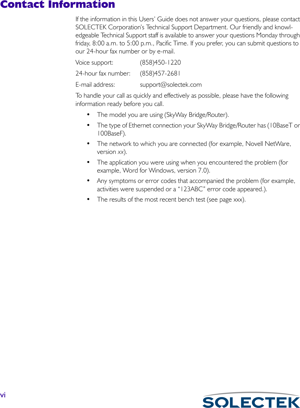


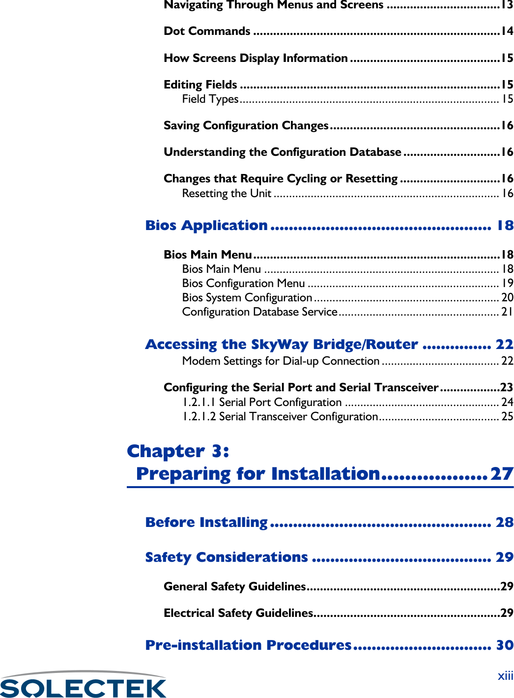


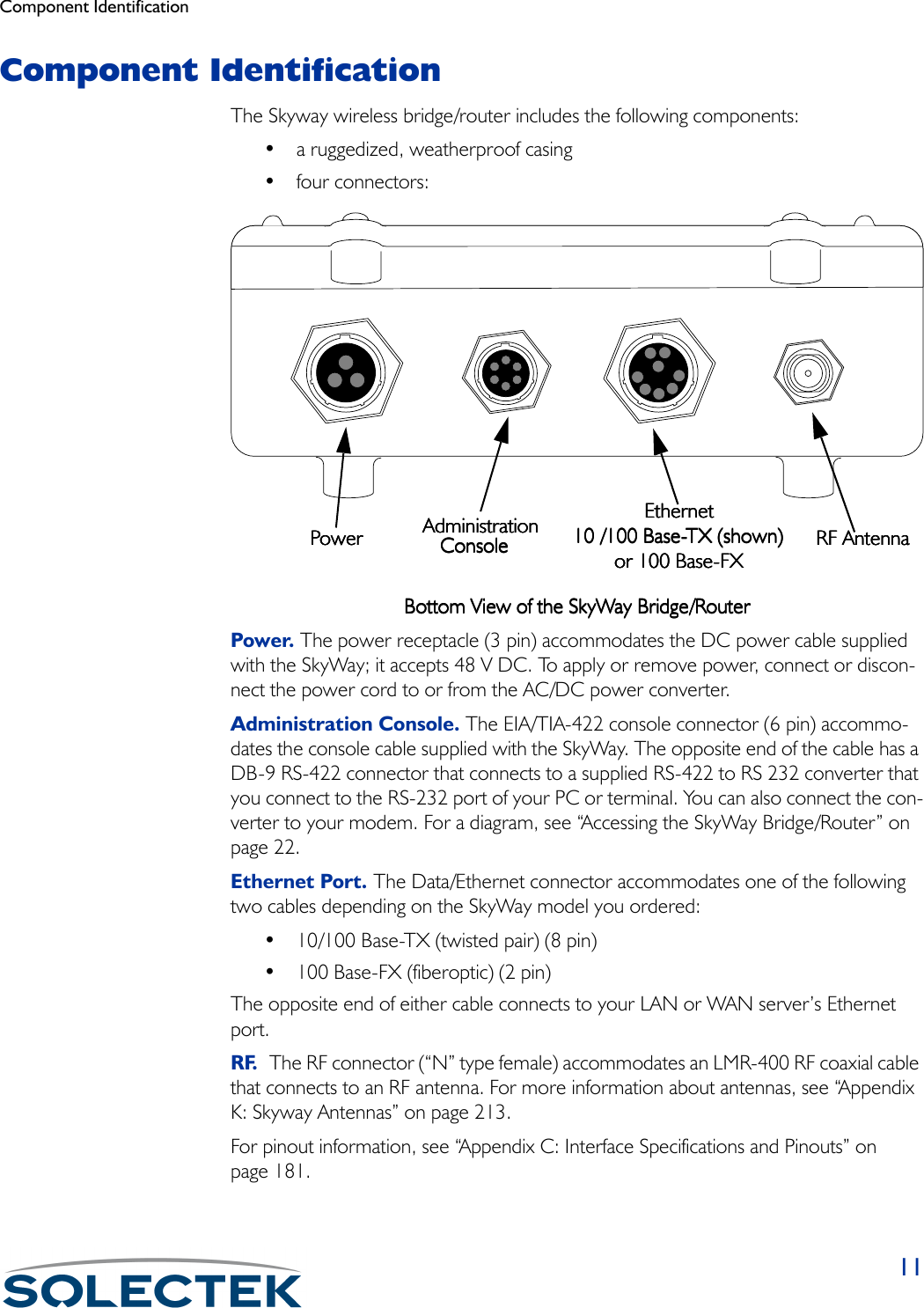


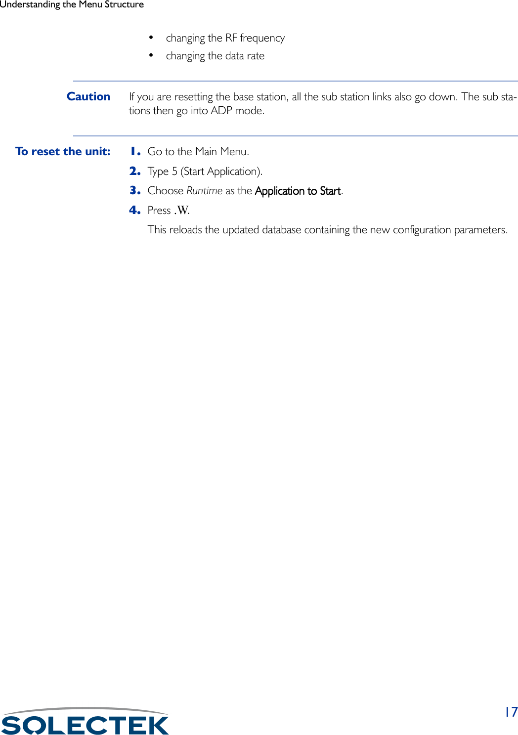

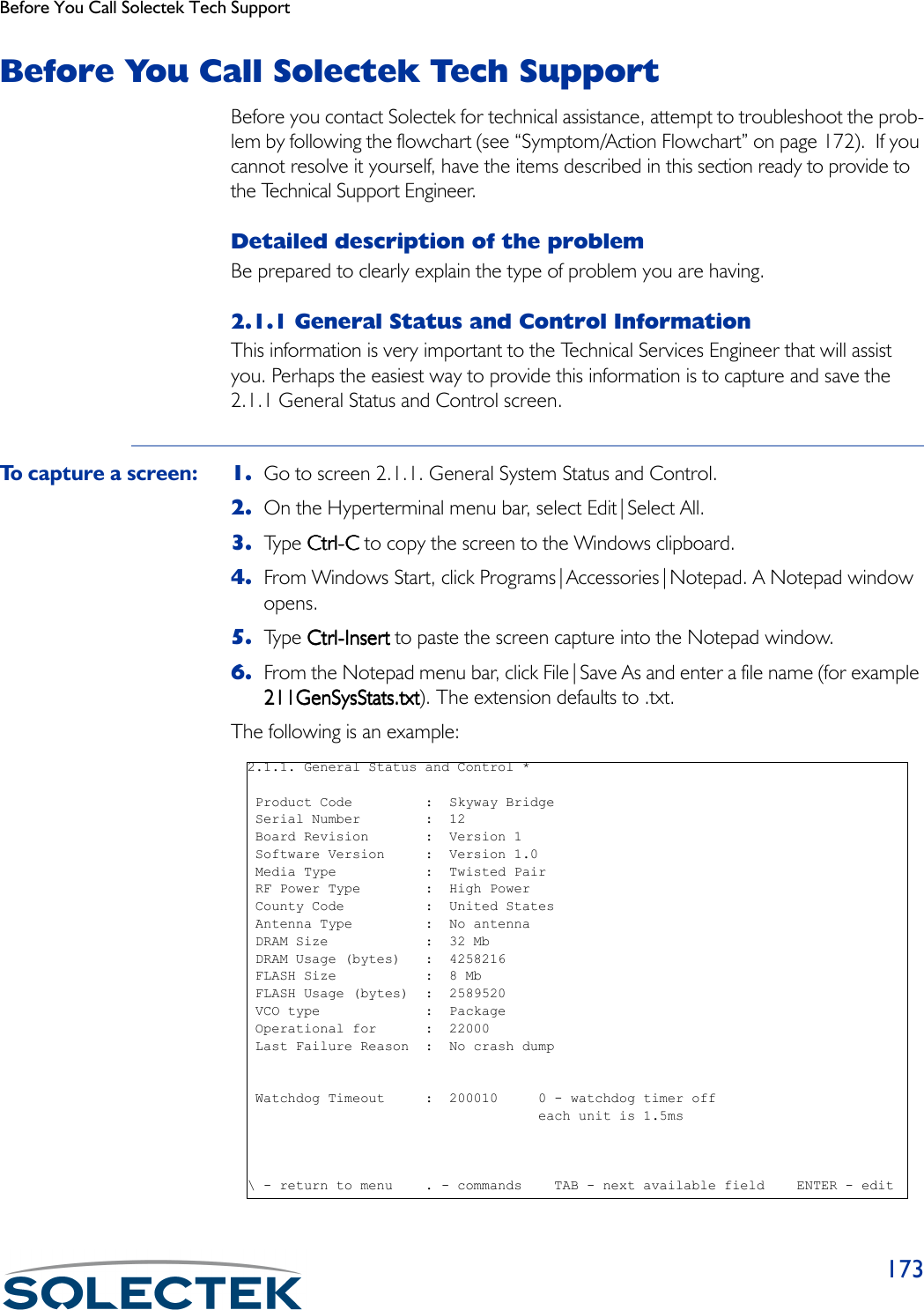
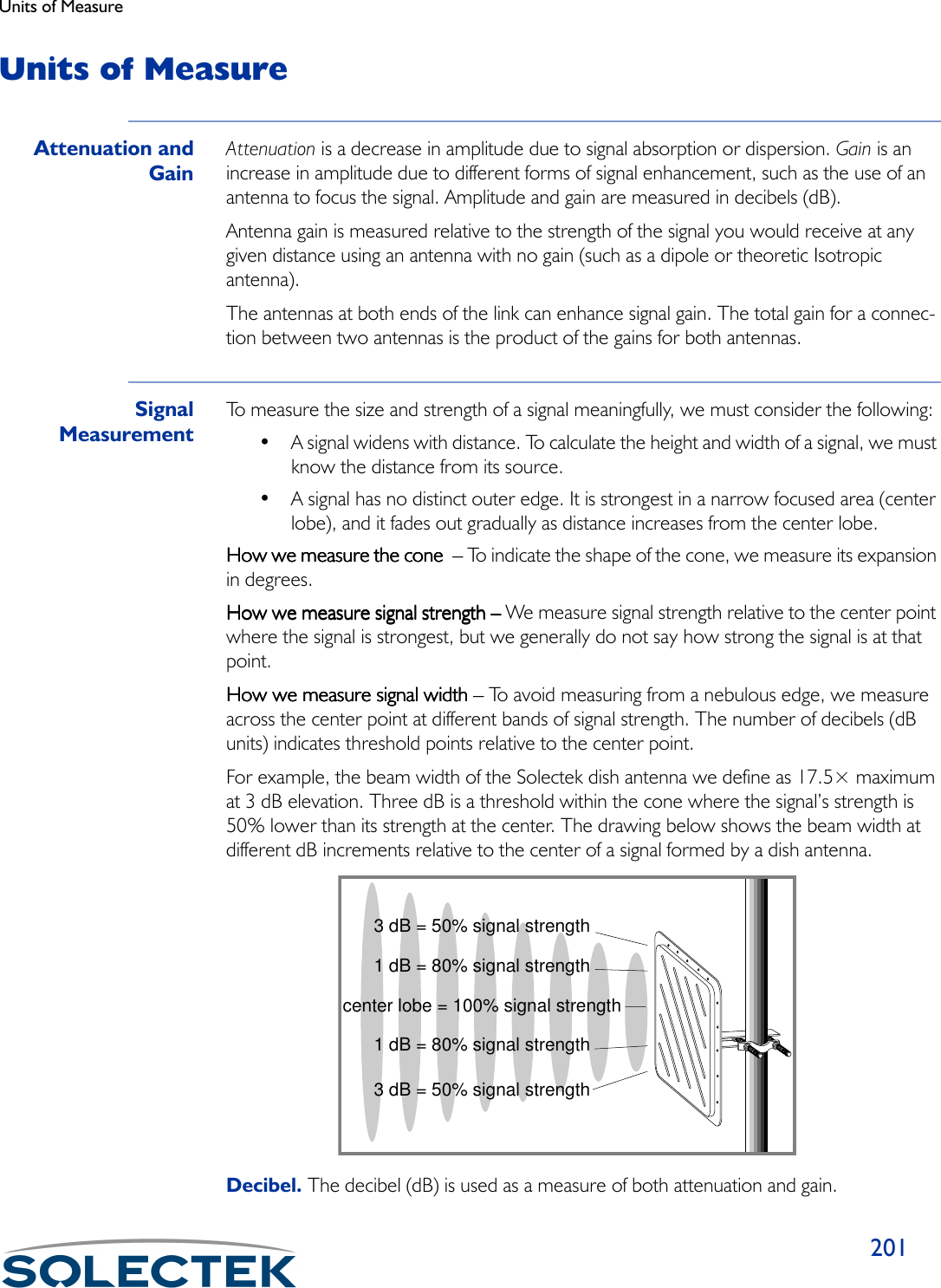
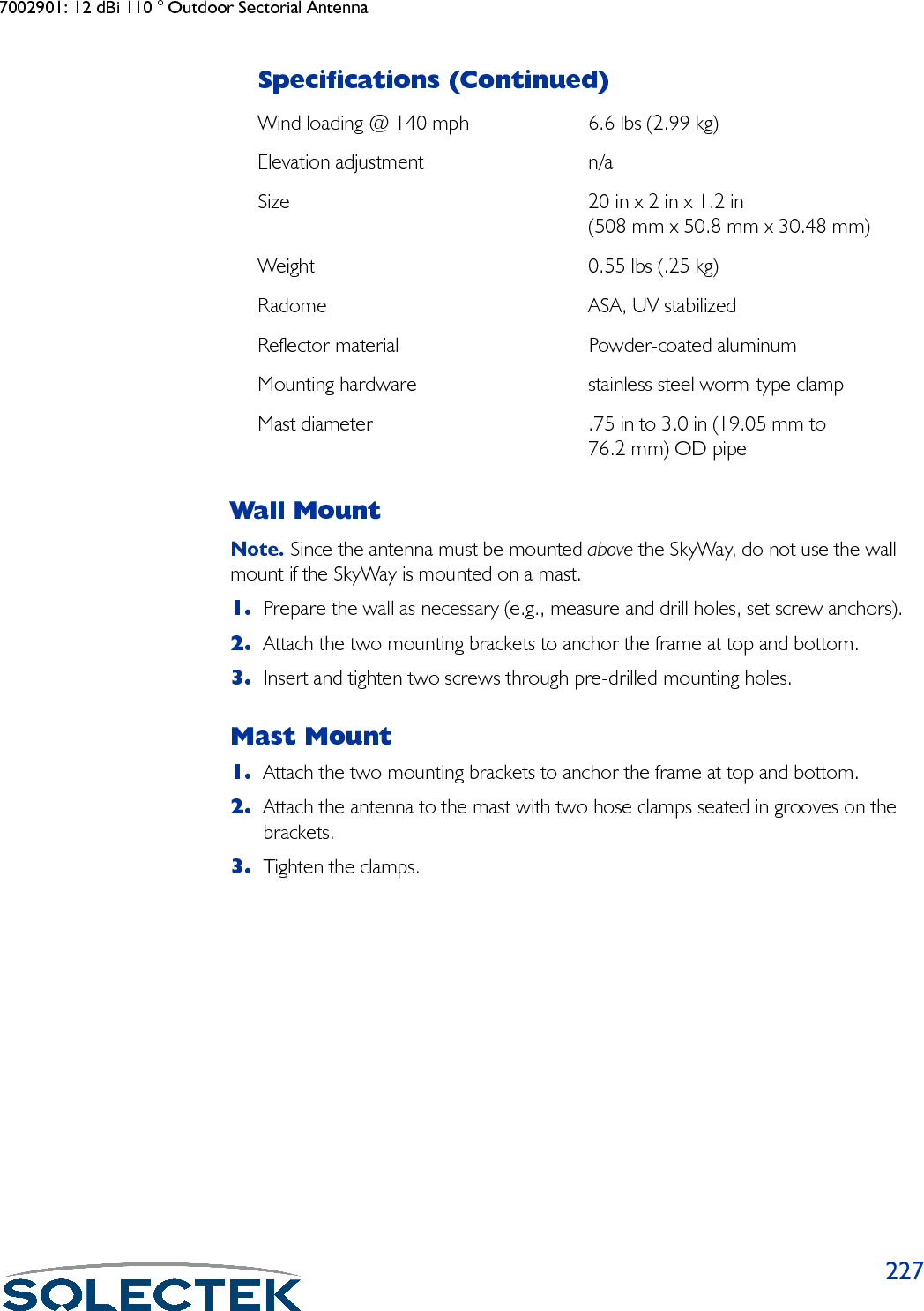
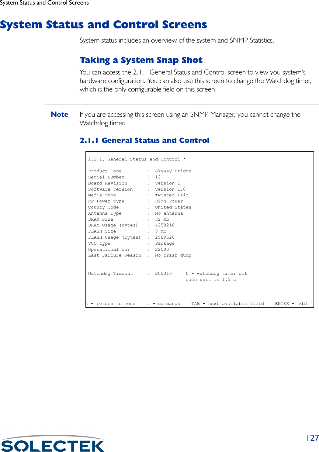
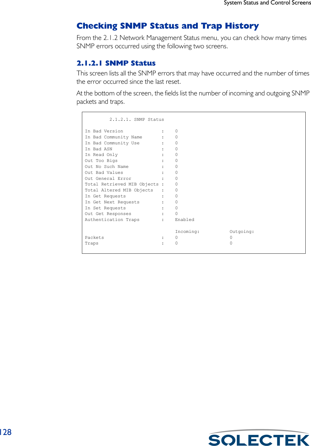
![241.2.1.1 Serial Port ConfigurationField Name MIB Default SettingPort Number [swSerialPortIndex] 1The serial port number is 1.Configuration Status [swSerialPortConfigSta-tus]On-lineWhether this port configuration initializes upon reset. On-line means the port comes up as a serial port when the unit is reset; Off-line means the port does not initialize upon reset.Buffers [swSerialPortMaxBuffers] 80Serial port buffers.Transmit Buffers [swSerialPortTransDesc] 16Serial port transmit buffers.Receive Buffers [swSerialPortRecvDesc] 16Serial port receive buffers.Maximum Frame Size [swSerialPortMaxFrame-Size]512Largest frame that can be transmitted vial the serial port 1.2.1.1 Serial Port Configuration Port Number : 1 Configuration Status : On-line Buffers : 80 Transmit Buffers : 12 Receive Buffers : 12 Maximum Frame Size : 512\ - return to menu . - commands TAB - next available field ENTER - edit](https://usermanual.wiki/Solectek/24WAN5.Soletek-Skyway-Final-User-Guide/User-Guide-91948-Page-50.png)
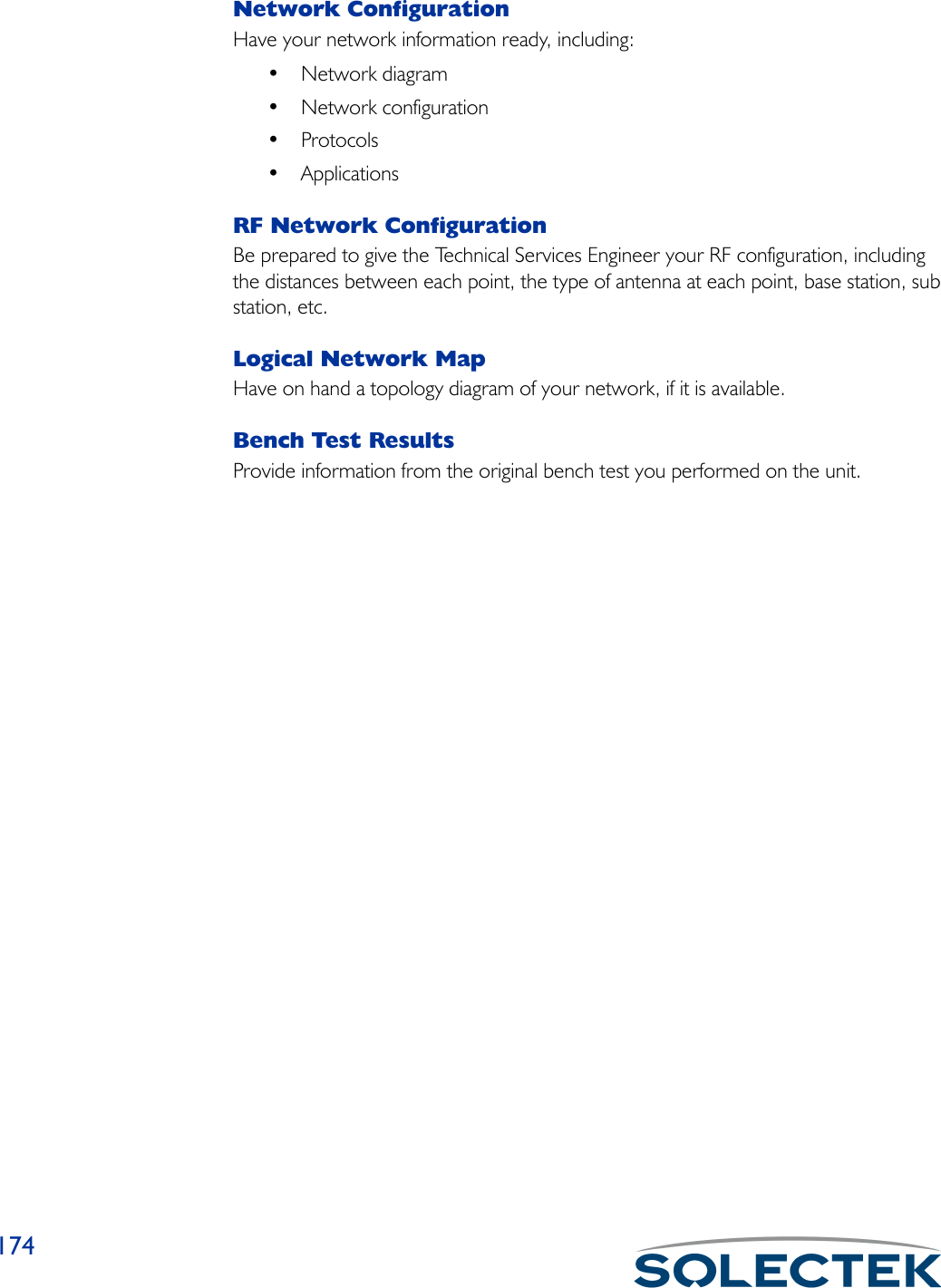
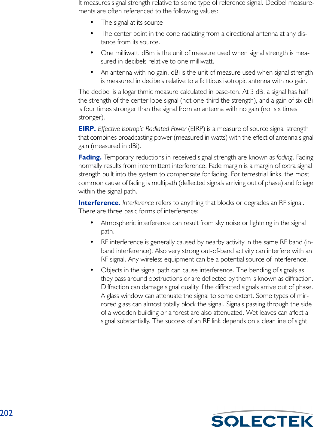
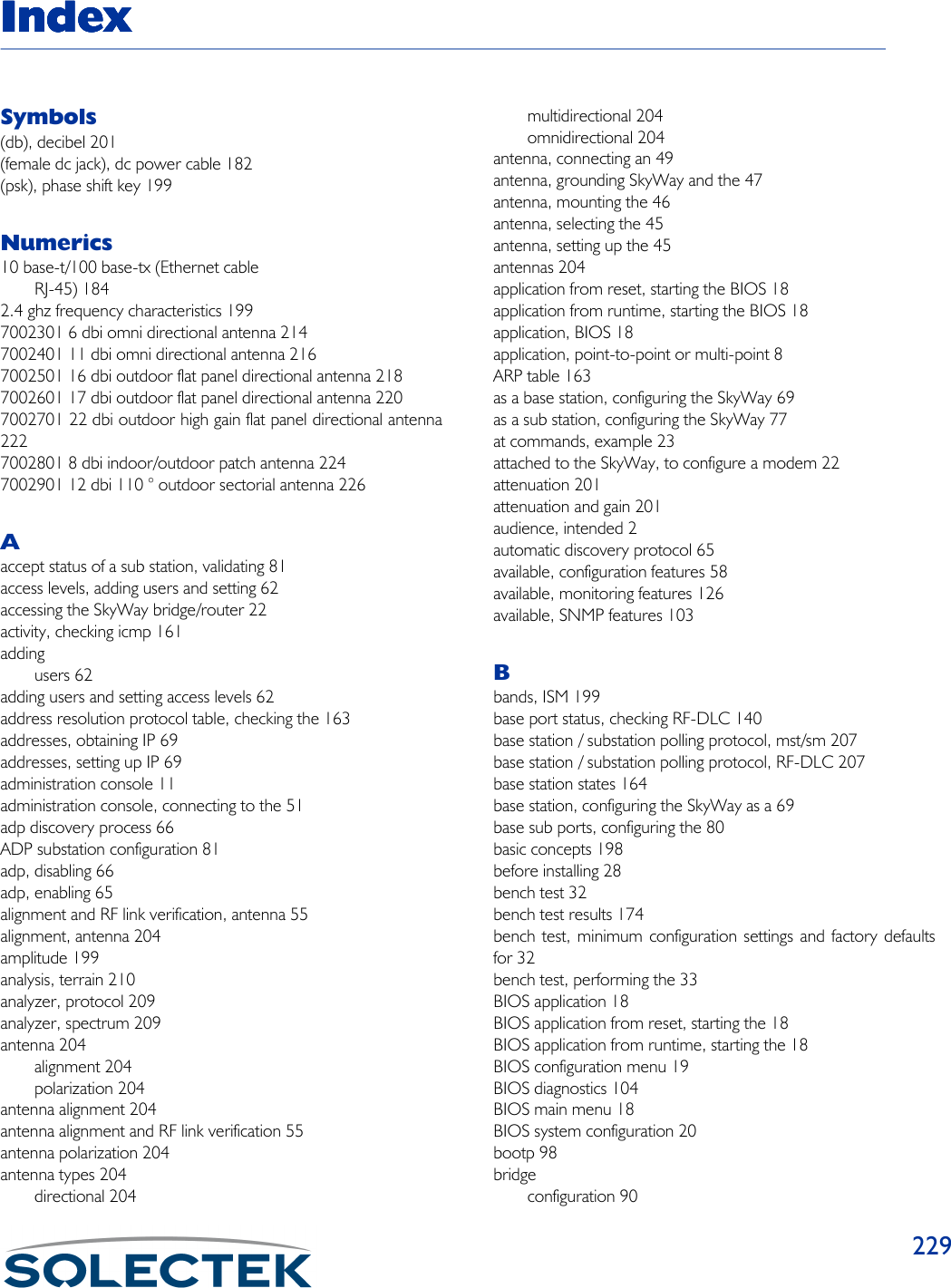
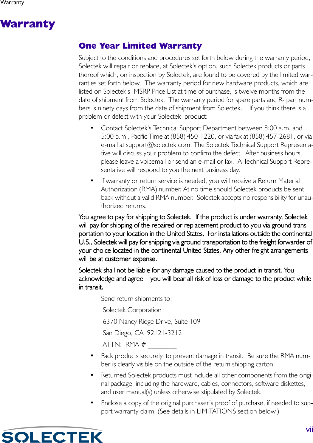
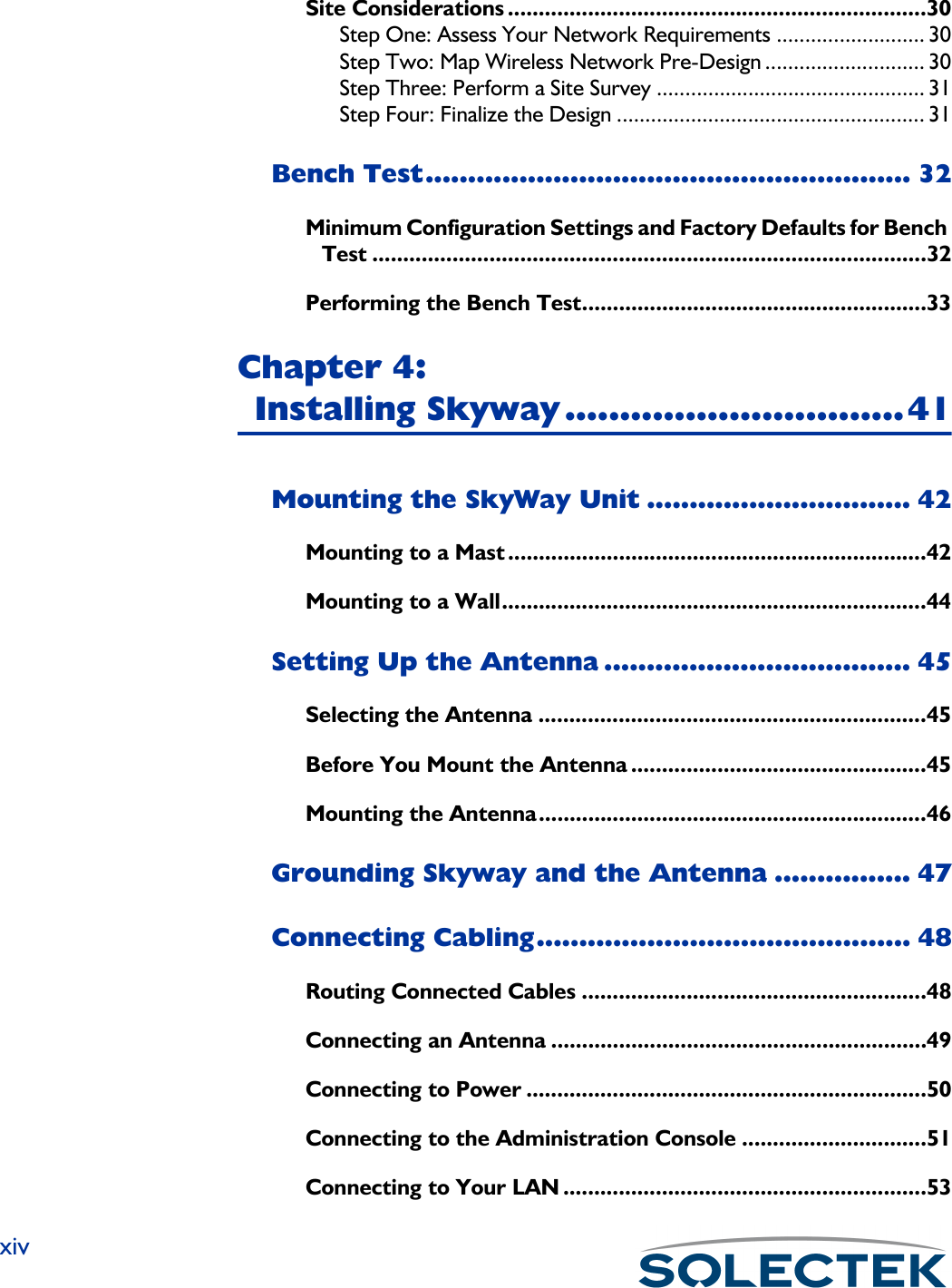
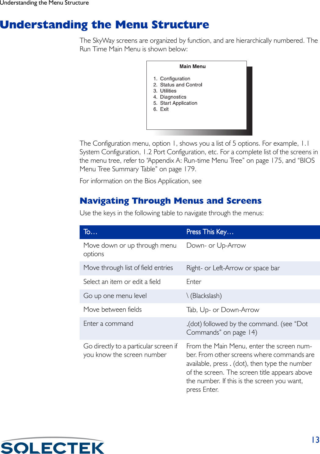
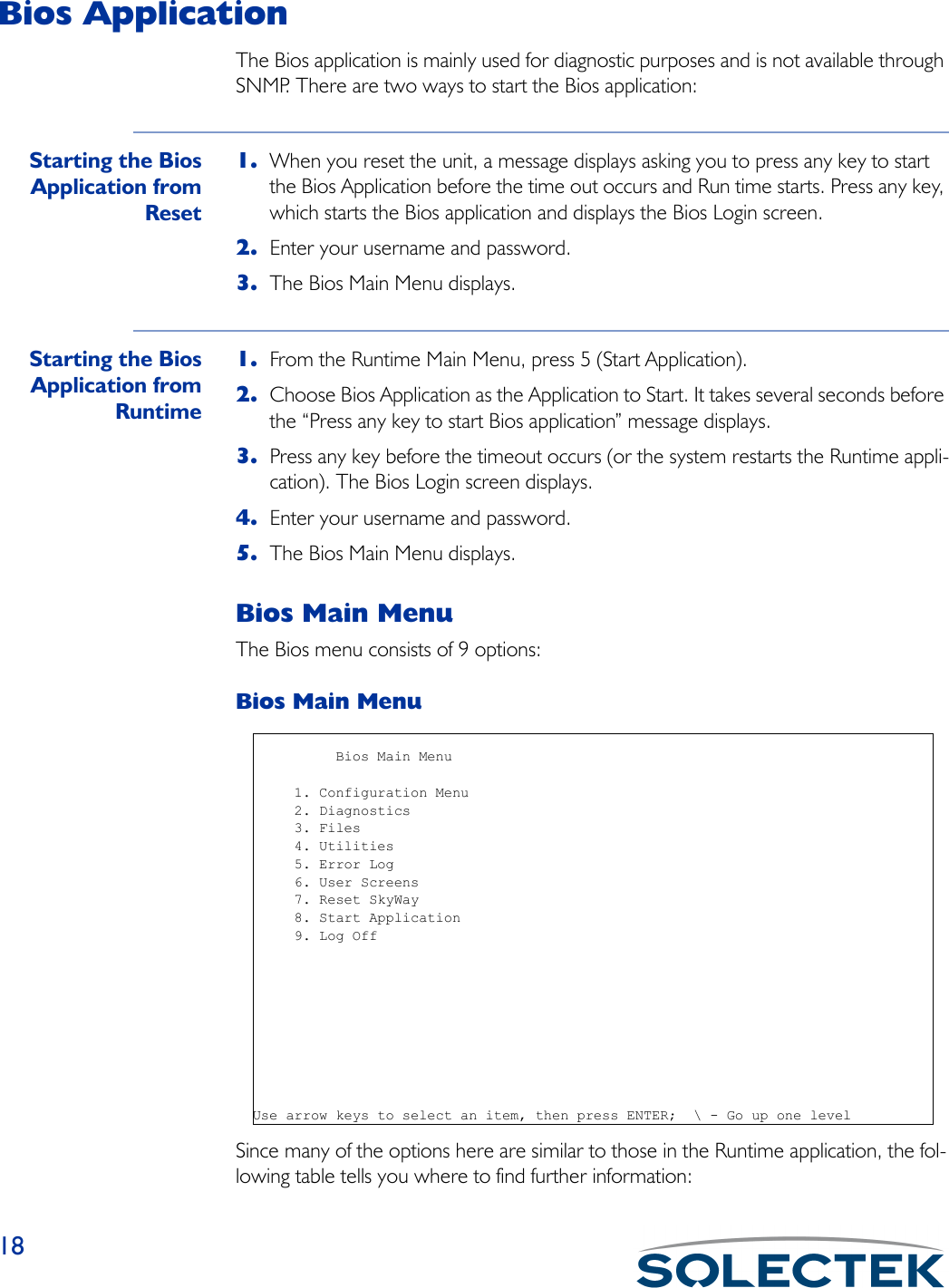
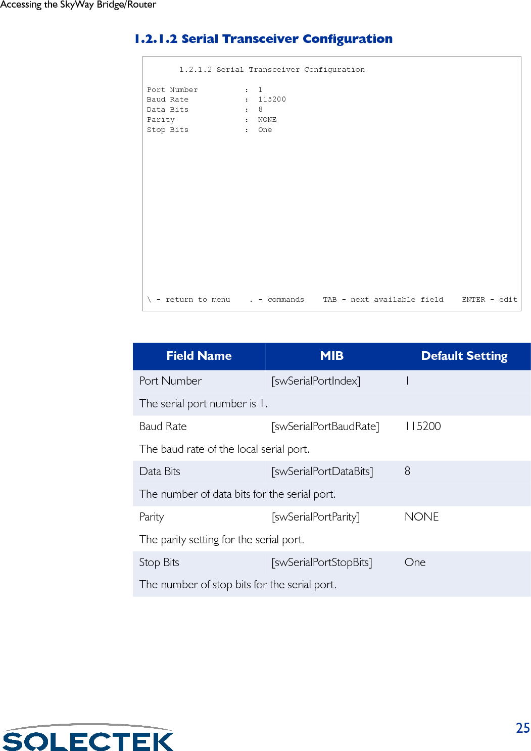
![Accessing the SkyWay Bridge/Router251.2.1.2 Serial Transceiver ConfigurationField Name MIB Default SettingPort Number [swSerialPortIndex] 1The serial port number is 1.Baud Rate [swSerialPortBaudRate] 115200The baud rate of the local serial port.Data Bits [swSerialPortDataBits] 8The number of data bits for the serial port.Parity [swSerialPortParity] NONEThe parity setting for the serial port.Stop Bits [swSerialPortStopBits] OneThe number of stop bits for the serial port. 1.2.1.2 Serial Transceiver Configuration Port Number : 1 Baud Rate : 115200 Data Bits : 8 Parity : NONE Stop Bits : One \ - return to menu . - commands TAB - next available field ENTER - edit](https://usermanual.wiki/Solectek/24WAN5.Soletek-Skyway-Final-User-Guide/User-Guide-91948-Page-51.png)


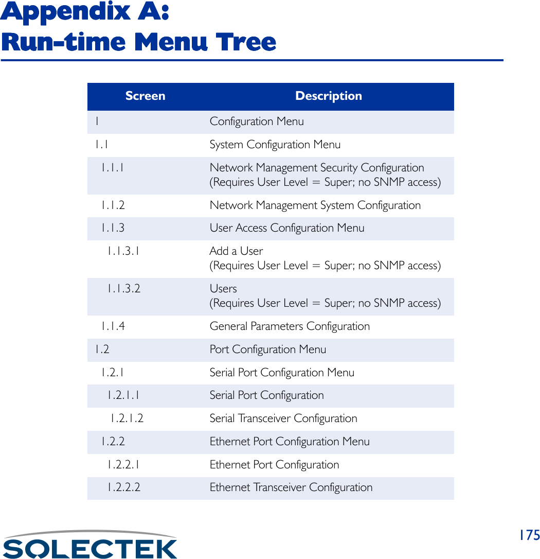
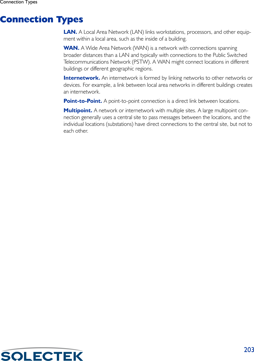
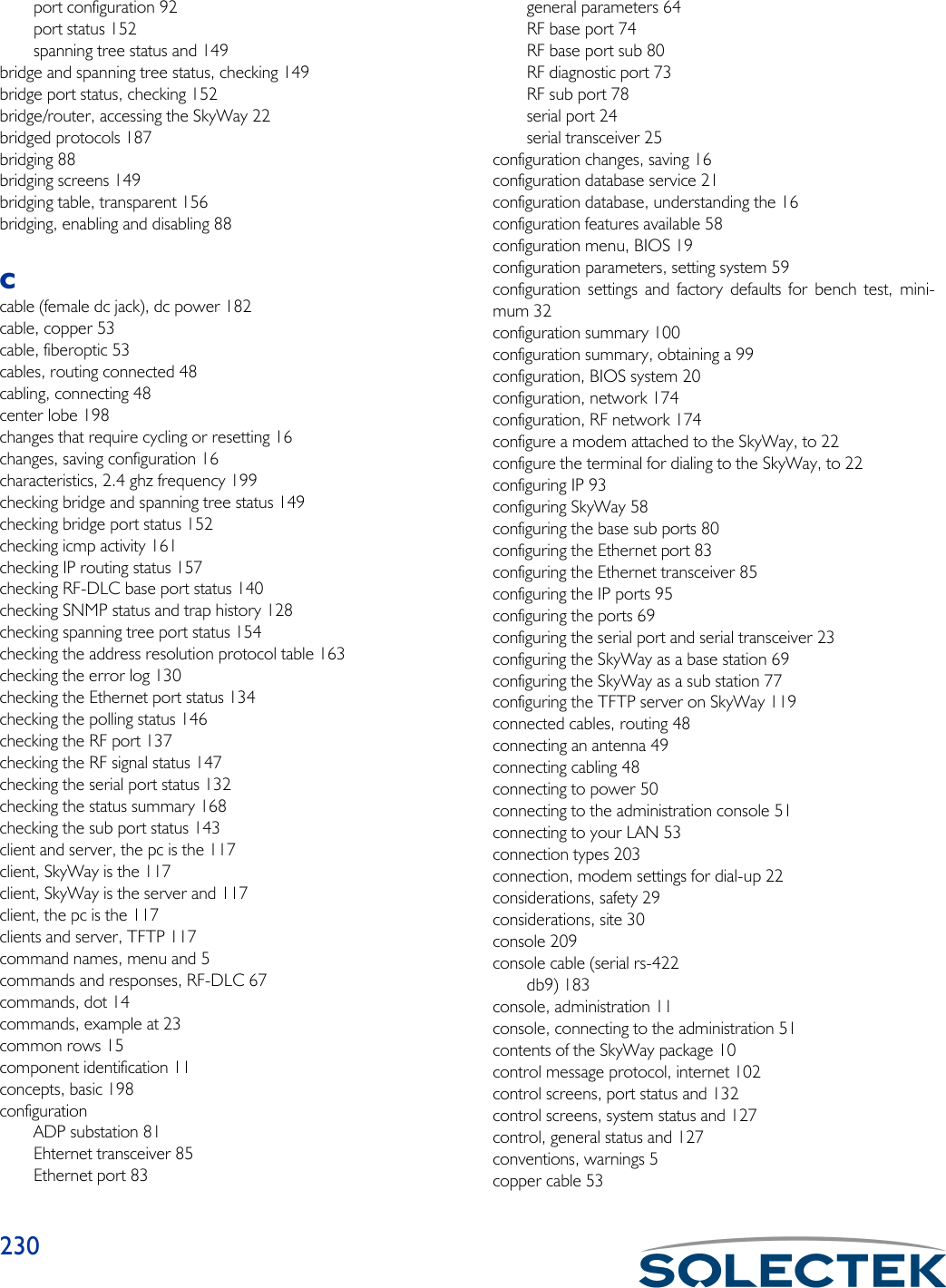
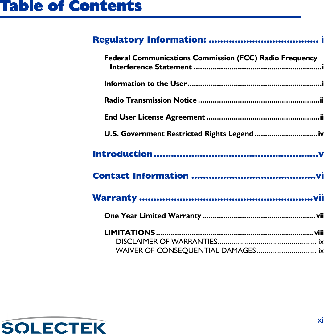
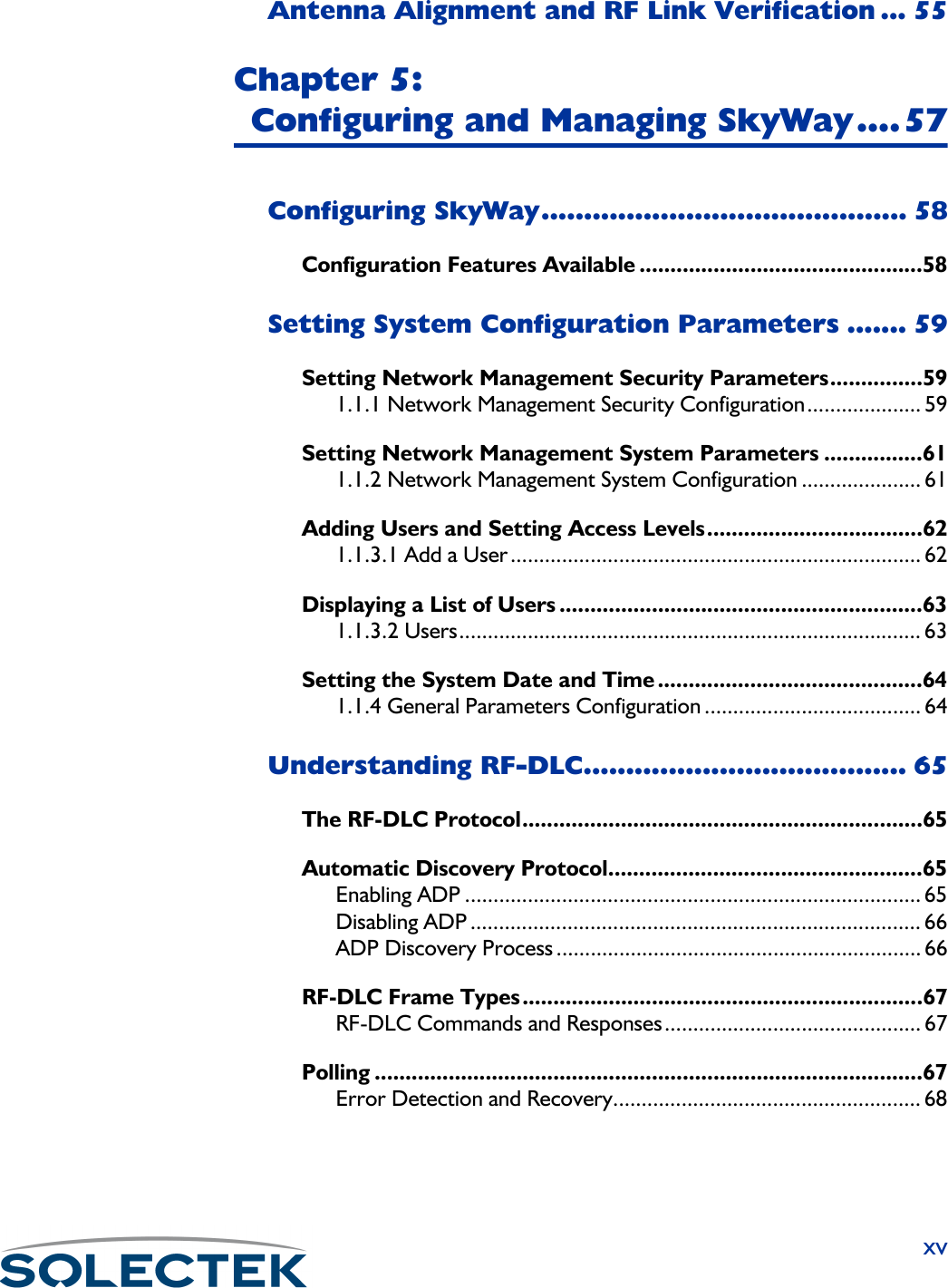
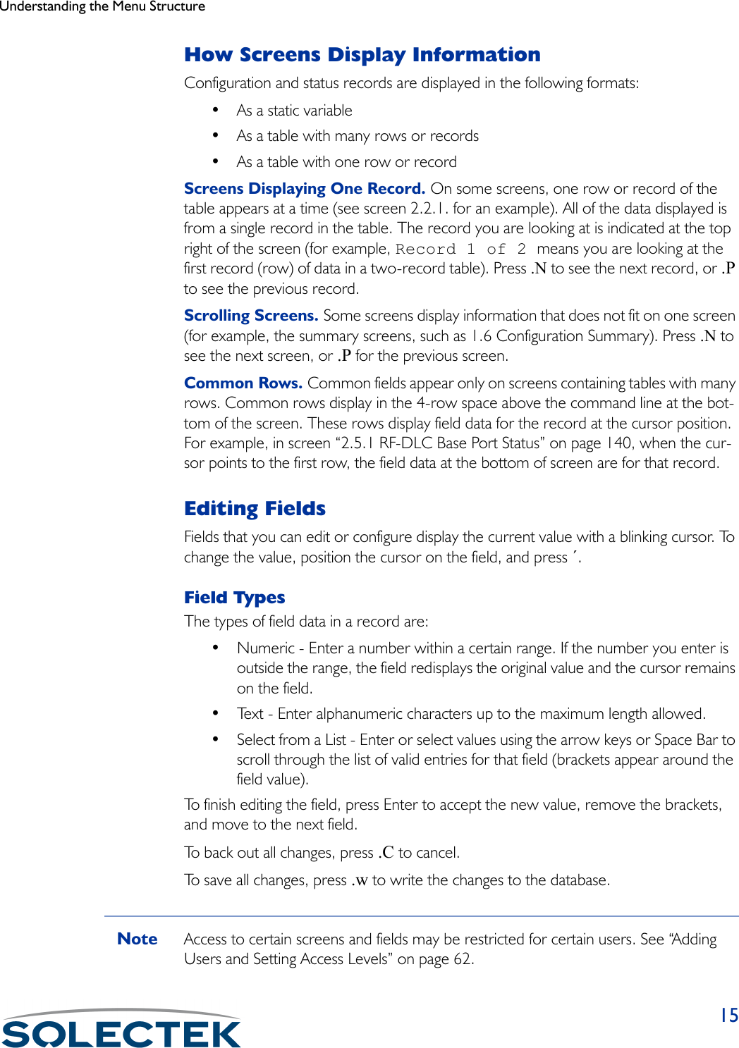
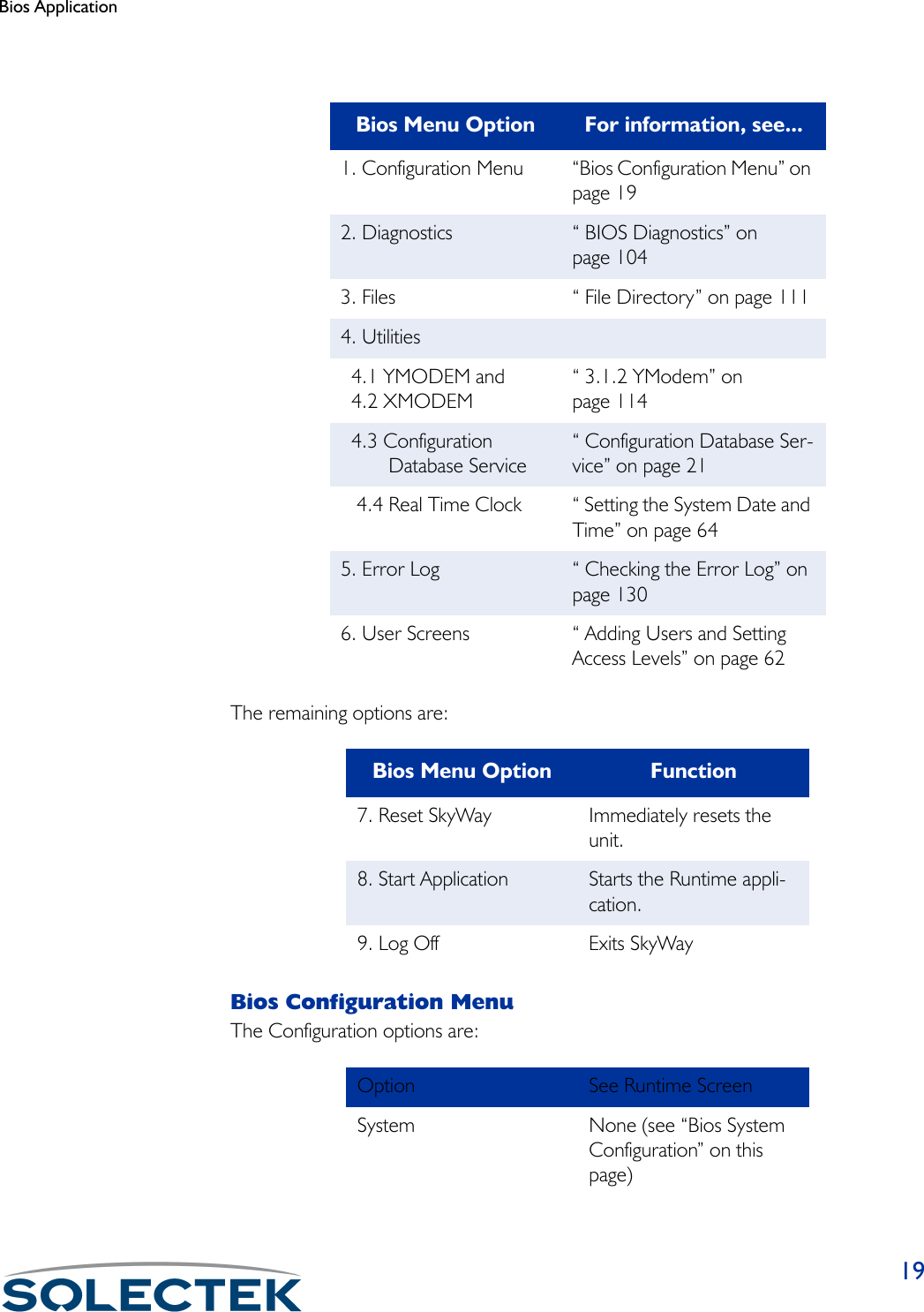
![721.2.3.3 RF Transceiver ConfigurationUse this screen to set RF Frequency, RF Data Rate, and Scrambler Tap values.Field Name MIB Settings (default in bold)RF Port [swRFTransCfgIndex] 3The RF port number is 3.RF Frequency [swRFTransCfgFre-quency]2468 MhzThe transmitted and received frequency for this SkyWay. This setting must match all other stations communicating with this SkyWay.RF Data Rate [swRFTransCfgDataRate] • 2 Mbps• 5.5 Mbps• 11 MbpsThis setting must match all other stations communicating with this SkyWay.Scrambler Tap [swRFTransCfgScramb-lerTap]72Determines how the SkyWay scrambles data between two units. This setting must match all other stations communicating with this SkyWay.1.2.3.3. RF Transceiver Configuration Record 1 of 1 RF Port RF Frequency RF Data Rate Scrambler Tap ------- ------------ ----------- ------------ 3 2468 Mhz 2 Mbps 72\ - return to menu . - commands TAB - next available field ENTER - edit](https://usermanual.wiki/Solectek/24WAN5.Soletek-Skyway-Final-User-Guide/User-Guide-91948-Page-98.png)
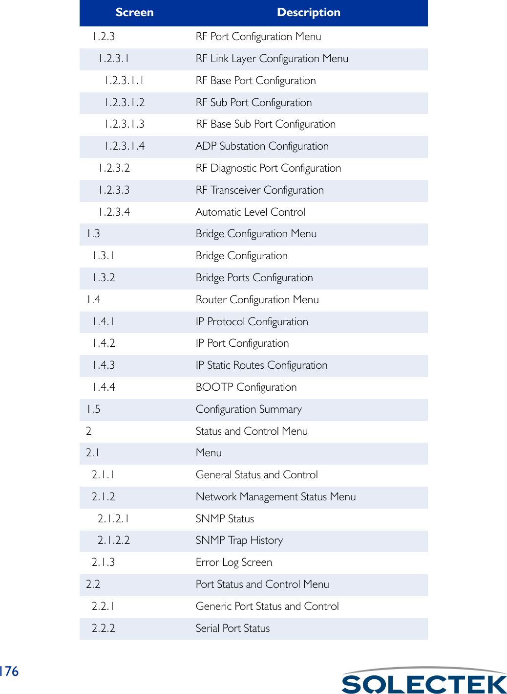
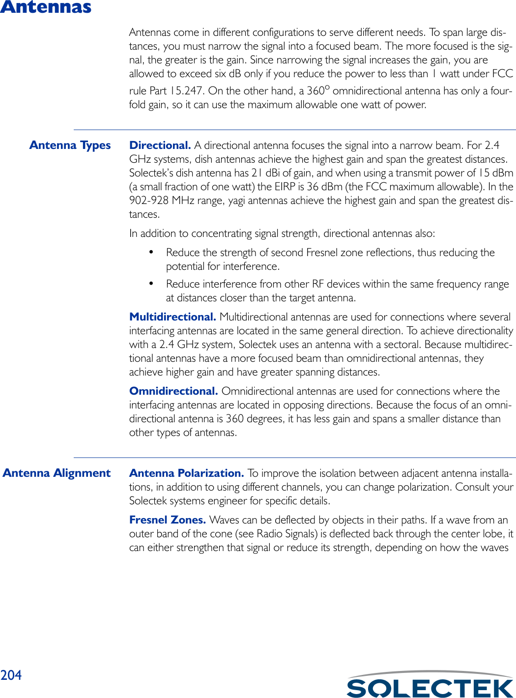
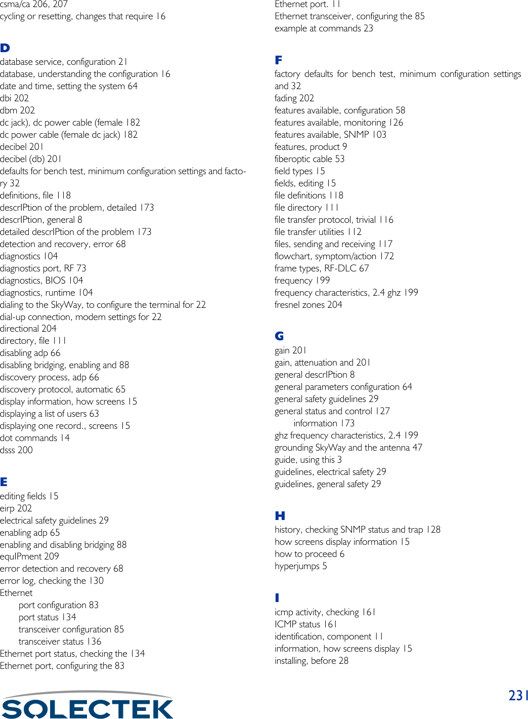
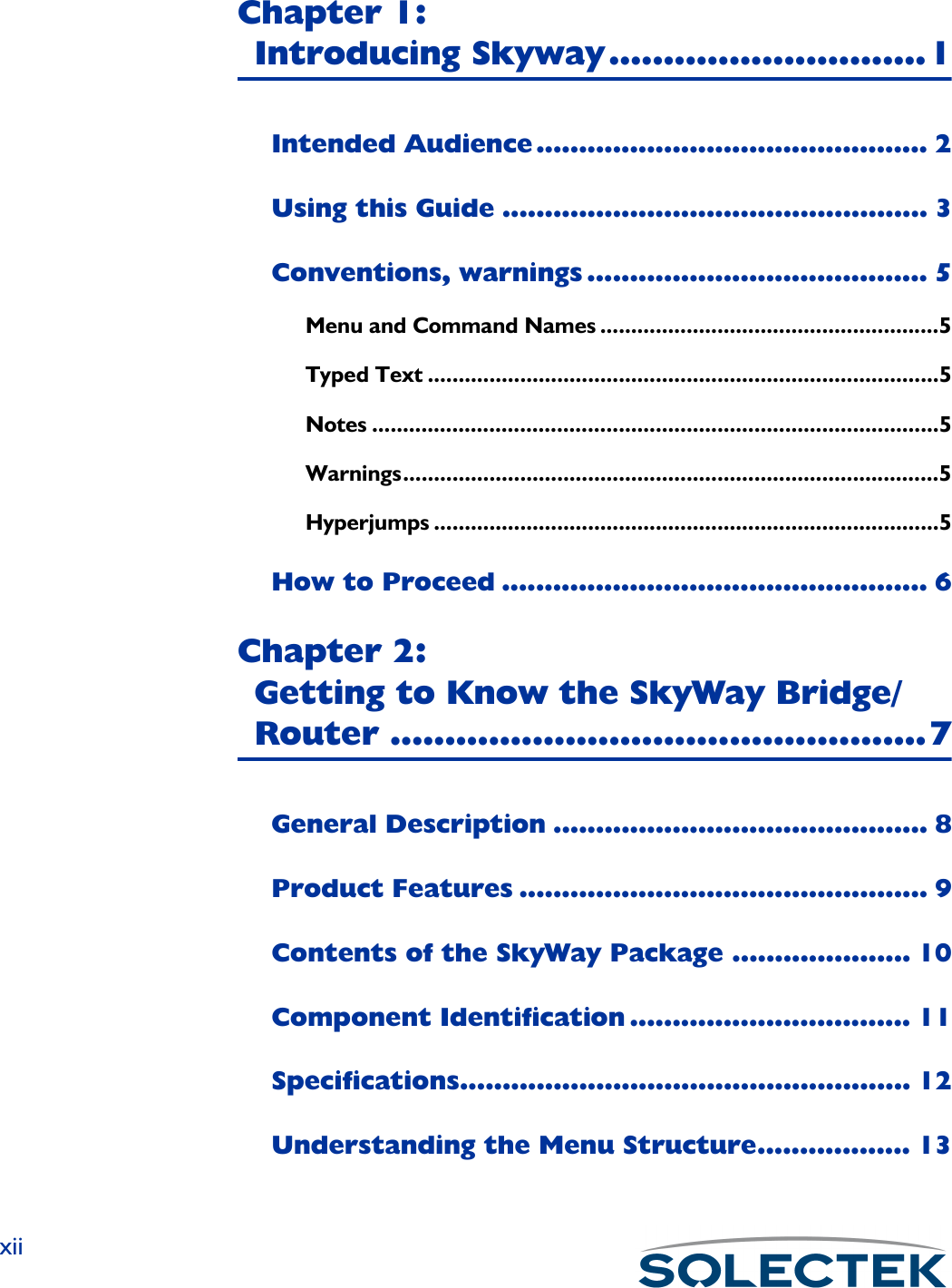
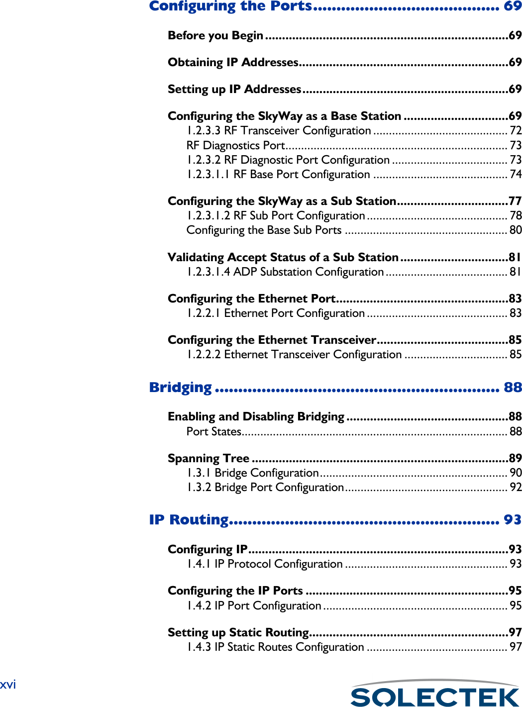
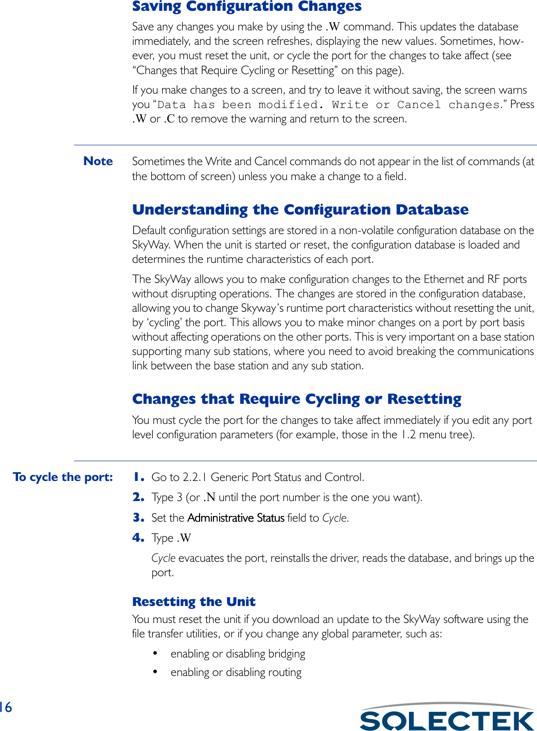
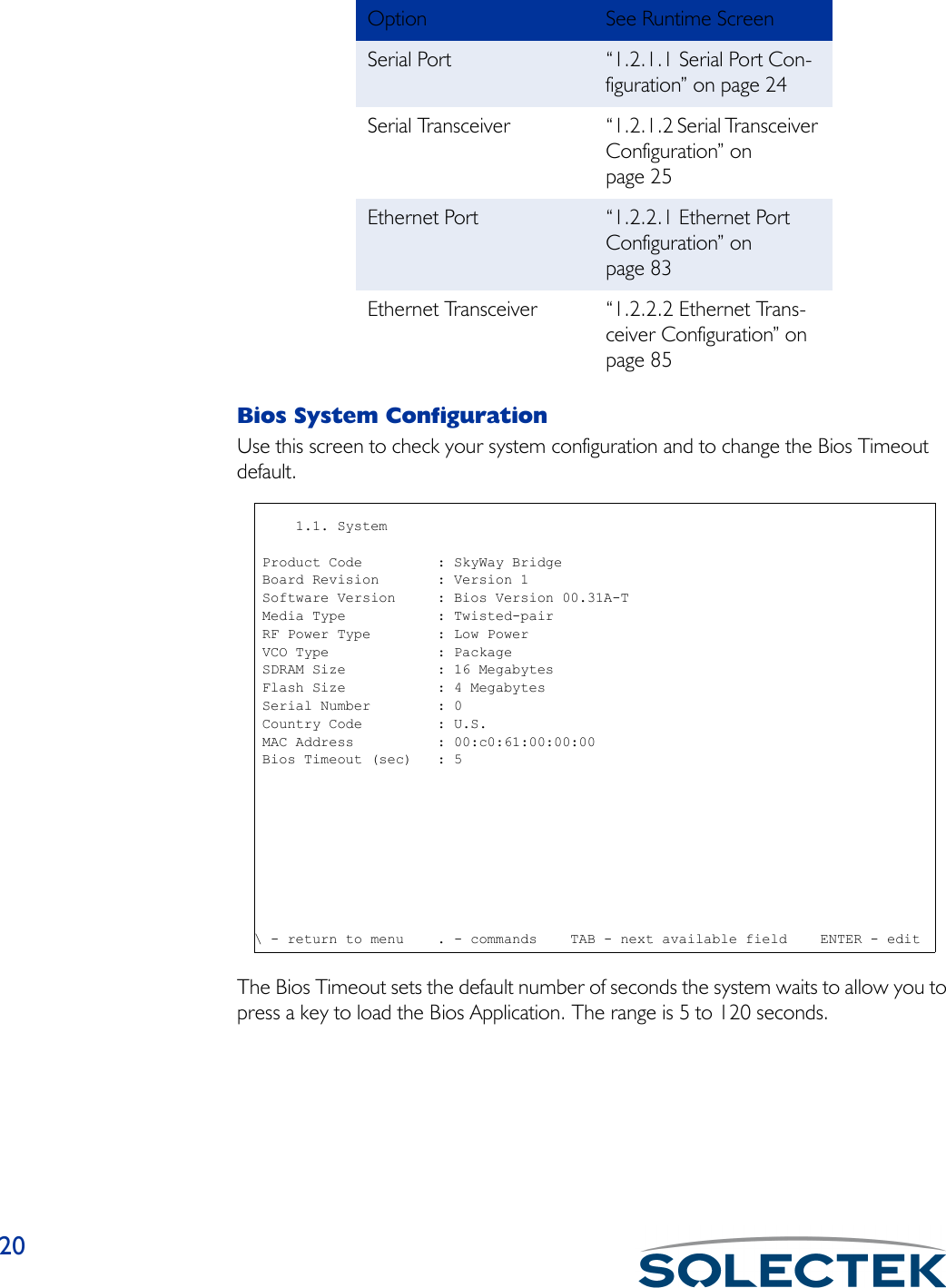
![Configuring the Ports73RF Diagnostics PortThere are two diagnostic ports, the RF-DLC Base Diagnostic port and the RF-DLC Sub Diagnostic port. Both of these use the control interface of the RF driver to perform RF diagnostics.1.2.3.2 RF Diagnostic Port ConfigurationThe following table lists the field name, the MIB name, and field options with the default setting in bold:Field Name MIB Settings (default in bold)Port Number [swRFDiagPortIndex] 3The RF port number.Configuration Status [swRFDiagPortConfigSta-tus]• On-line• Off-lineDetermines if this port is initialized upon reset. Off-line prevents the port from being initialized upon reset.Port Type [swRFDiagPortPorttype] RF Sub Diagnostics PortRF Sub Diagnostic port.Max Buffers [swRFDiagPortMax-Buffers]800The number of message buffers.Transmit Buffers [swRFDiagPortTransDesc] 240The number of transmit buffers.1.2.3.2 RF Diagnostic Port Configuration Record 1 of 3 Port Number :3 Configuration Status :On-line Port Type :RF-DLC SUB Diagnostic Port Max Buffers :800 Transmit Buffers :240 Receive Buffers :180 Maximum Frame Size :1549 Record Type :Valid\ - return to menu . - commands TAB - next available field ENTER - edit](https://usermanual.wiki/Solectek/24WAN5.Soletek-Skyway-Final-User-Guide/User-Guide-91948-Page-99.png)
![741.2.3.1.1 RF Base Port ConfigurationThe following table lists the field name, MIB, and settings with the default setting in bold. If only one setting is shown, it is the default:Receive Buffers [swRFDiagPortRecvDesc] 180The number of receive buffers.Maximum Frame Size [swRFDiagPortmax-FrameSize]3200The physical MTU, or largest frame that can be transmitted. This field is not config-urable.Record Type [swRFDiagPort] • Valid• InvalidThe status of this configuration.Field Name MIB Settings (default in bold)Port Number [swRFBasePortIndex] 3The RF port number.Field Name MIB Settings (default in bold) 1.2.3.1.1 RF Base Port Configuration Record 1 of 1 Port Number : 3 Configuration Status : Off-line Port Type : RF-DLC Base Port Max Buffers : 800 Transmit Buffers : 240 Receive Buffers : 180 Maximum Frame Size : 3200 Slow Polling Timeout-seconds : 15 First Sub Station Number : 256 Last Sub Station Number : 287 Automatic Discovery Protocol : Enabled ADP Mode : Auto Acceptance ADP Timeout Interval-seconds : 60 Record Type : Valid\ - return to menu . - commands TAB - next available field ENTER - edit](https://usermanual.wiki/Solectek/24WAN5.Soletek-Skyway-Final-User-Guide/User-Guide-91948-Page-100.png)
![Configuring the Ports75Configuration Status [swRFBasePortConfigSta-tus•••• Off-lineOff-lineOff-lineOff-line• On-lineDetermines if the port is initialized upon reset. Off-line prevents the port from initial-izing upon reset.Port Type [swRFBasePortPortType] RF-DLC Base PortThis is a read-only field that defines this port as a base port.Max Buffers [swRFBasePortMax-Buffers]800The number of message buffers allocated to this base port.Transmit Buffers [swRFBasePortTrans-Desc]240The number of transmit buffers.Receive Buffers [swRFBasePortRecvDesc] 180The number of receive buffers.Maximum Frame Size [swRFBasePortMax-FrameSize]3200This is a read-only field that sets the physical MTU, or largest frame that can be transmitted from this port.Slow Polling Timeout [swRFBasePortSlow-PollTO]15 secondsThe slow poll time out interval in seconds.First Sub Station Number [swRFBasePortFirstSub-Addr]256The first possible sub station number. Last Sub Station Number [swRFBasePortLastSub-Addr]287The last possible sub station number.Automatic Discovery Pro-tocol[swRFBasePortADP] ••••EnabledEnabledEnabledEnabled• DisabledDetermines if Automatic Discovery Protocol is running. If enabled, you must also specify the ADP mode.Field Name MIB Settings (default in bold)](https://usermanual.wiki/Solectek/24WAN5.Soletek-Skyway-Final-User-Guide/User-Guide-91948-Page-101.png)
![76ADP Mode [swRFBasePortADP-Mode]Auto AcceptanceApplies only if ADP is enabled. Auto Acceptance means the base station automati-cally accepts sub stations. Manual Acceptance means you must manually accept the sub stations (see “1.2.3.1.4 ADP Substation Configuration” on page 81).ADP Timeout Interval - seconds[swRFBasePortADPTO] 60Applies only if ADP is enabled. Determines how often (in seconds) the base stations sends an ADP broadcast.Record Type: [swRFBasePortType] • Invalid• ValidIndicates the status of this base port configuration. If valid, this base port configura-tion is enabled. If invalid, this port is removed as a base port after the next reset.Field Name MIB Settings (default in bold)](https://usermanual.wiki/Solectek/24WAN5.Soletek-Skyway-Final-User-Guide/User-Guide-91948-Page-102.png)
![781.2.3.1.2 RF Sub Port ConfigurationNote Ty p e .A to begin editing the screen.Use this screen to set the sub station port parameters. The following table lists the field name, MIB, and the default, or field options with the default in bold:1.2.3.1.2 RF Sub Port Configuration Record 0 of 0 Port Number :3 Configuration Status :On-line Port Type :RF-DLC Sub Port Max Buffers :800 Transmit Buffers :240 Receive Buffers :180 Maximum Frame Size :3200 Sub Station Number :0 Link down Timeout Interval (1.5 msec) :320 Record Type :Valid\ - return to menu . - commands TAB - next available field ENTER - editField Name MIB Settings (default in bold)Port Number: [swRFSubPortIndex] 3The RF physical port number is 3.Configuration Status: [swRFSubPortConfigSta-tus]•••• On-lineOn-lineOn-lineOn-line• Off-lineDetermines if the port is initialized when a reset occurs. Set Off-line to prevent the port from initializing upon reset. Online initializes the port upon reset.Port Type [swRFSubPortPortType] Sub PortThis read-only field defines this port as a sub station port.Max Buffers: [swRFSubPortMaxBuffers] 800The number of message buffers allocated to this sub station port.Transmit Buffers: [swRFSubPortTransDesc] 338The number of transmit buffers.Receive Buffers: [swRFSubPortRecvDesc] 140](https://usermanual.wiki/Solectek/24WAN5.Soletek-Skyway-Final-User-Guide/User-Guide-91948-Page-104.png)
![Configuring the Ports79The number of receive buffers.Maximum Frame Size: [swRFSubPortMaxFrame-Size] 3200This read-only field sets the maximum frame size for each frame originating from this port.Sub Station Number [swRFSubPortStation-Num]0Sub Station number for this sub station. If ADP is enabled, set this parameter to zero.Link Down Timeout Interval [swRFSubPortLinkTO] SecondsThe length of time this substation tries to link up to the base station.Record Type [swRFSubPortType] • Valid• InvalidIndicates the status of this port configuration. If valid, this port configuration is enabled. If marked as invalid, after the next reset or port cycle, this port will not exist as a sub station port.Field Name MIB Settings (default in bold)](https://usermanual.wiki/Solectek/24WAN5.Soletek-Skyway-Final-User-Guide/User-Guide-91948-Page-105.png)
![80Configuring the Base Sub PortsIf you have disabled ADP, you must manually configure the base sub ports on the base station using the 1.2.3.1.3 RF Base Sub Port Configuration screen. If you have ADP enabled, you do not need to configure base sub ports.1.2.3.1.3 RF Base Sub Port ConfigurationNote Ty p e .A to add a base sub port and to begin editing.The following table lists the field name, MIB, and the default or field options with the default setting in bold:1.2.3.1.3 RF Base Sub Port Configuration Record 1 of 1 Sub Station Number :256 Configuration Status :On-line Port Type :RF-DLC Base to Sub Port Corresponding Substation RF Port IP Address :000.000.000.000 Record Type :Valid\ - return to menu . - commands TAB - next available field ENTER - editField Name MIB Settings (default in bold)Sub Station Number [swRFBaseSubPortIndex] 256The sub station number for this Base to Sub station port.Configuration Status [swRFBaseSubPortCon-figStatus]•••• On-lineOn-lineOn-lineOn-line• Off-lineDetermines if the port is enabled during initialization (On-line). Set to off-line to dis-able the port.Port Type [swRFBaseSubPortPort-Ty p e ]RF-DLC Base to Sub PortThis read-only field defines this port as a RF-DLC Base to Sub station port.Corresponding Substation RF Port IP Address [swRFBaseSubPortSub-RFIPAddr]000.000.000.000The IP address of the sub station.](https://usermanual.wiki/Solectek/24WAN5.Soletek-Skyway-Final-User-Guide/User-Guide-91948-Page-106.png)
![Configuring the Ports81Validating Accept Status of a Sub StationThis section applies only if you set ADP mode to Manual Acceptance. Use screen 1.2.3.1.4 ADP Substation Configuration to validate the accept status for each sub sta-tion listed. The screen only shows sub stations that have not yet been accepted by the base station. Once they are accepted, they appear in screen 2.5.2 RF-DLC Sub Port Status, described in detail on page 143.1.2.3.1.4 ADP Substation ConfigurationRecord Type [swRFBaseSubPortType] •••• ValidValidValidValid• InvalidIndicates the status of this RF Sub station port configuration. If valid, this port config-uration is enabled. If marked as invalid, this record will be deleted after the next reset.Field Name MIB Settings (default in bold)Sub Station Number [swADPStationIndex]The base sub port number of the sub station.Field Name MIB Settings (default in bold) 1.2.3.1.4 ADP Substation Configuration Record 1 of 1 Sub Station IP Accept Number Address Status--------- --------- ------- 256 196.028.145.069 No\ - return to menu . - commands TAB - next available field ENTER - edit](https://usermanual.wiki/Solectek/24WAN5.Soletek-Skyway-Final-User-Guide/User-Guide-91948-Page-107.png)
![82IP Address [swADPStationNetAd-dress]The IP address of the sub station.Accept Status [swADPStationStatus] • Yes••••NoNoNoNoEnter Yes to enable acceptance.Field Name MIB Settings (default in bold)](https://usermanual.wiki/Solectek/24WAN5.Soletek-Skyway-Final-User-Guide/User-Guide-91948-Page-108.png)
![Configuring the Ports83Configuring the Ethernet Port1.2.2.1 Ethernet Port ConfigurationField Name MIB Settings (default in bold)Port Number [swEtherPortIndex] 2The Ethernet port is 2.Configuration Status [swEtherPortConfigSta-tus]• On-line• Off-lineDetermines whether the port comes up at initialization time. You must reset the unit for changes to take affect.MAC Address [swEtherPortPhysAd-dress]The MAC address of this Ethernet port.Bridging Encap Type [swEtherPortBridgingEn-capType]• Ethernet II encap• Ethernet 802.3 encapEncapsulation used for bridging.Port Type [swEtherPortPortType] Ethernet 802.3This field is not configurable.1.2.2.1. Ethernet Port Configuration Record 1 of 1 Port Number : 2 Configuration Status : On-line MAC Address : 00:ba:d0:ba:be:00 Bridging Encap Type : Ethernet 802.3 encap Port Type : Ethernet 802.3 Buffers : 1200 Transmit Buffers : 256 Receive Buffers : 512 Maximum Frame Size : 1518 Record Type : Valid\ - return to menu . – commands TAB - next available field ENTER - edit](https://usermanual.wiki/Solectek/24WAN5.Soletek-Skyway-Final-User-Guide/User-Guide-91948-Page-109.png)
![84Buffers [swEtherPortMaxBuffers] 780The number of message buffers allocated to this Ethernet port.Transmit Buffers [swEtherPortTransDesc] 256The number of transmit buffers.Receive Buffers [swEtherPortRecvDesc] 256The number of receive buffers.Maximum Frame Size [swEtherPortMaxFrame-Size]1518The physical MTU.Record Type [swEtherPortType] • Valid• InvalidIf valid, this configuration is enabled upon reset. If invalid, this configuration record is deleted at the next reset.Field Name MIB Settings (default in bold)](https://usermanual.wiki/Solectek/24WAN5.Soletek-Skyway-Final-User-Guide/User-Guide-91948-Page-110.png)
![Configuring the Ports85Configuring the Ethernet Transceiver1.2.2.2 Ethernet Transceiver ConfigurationField Name MIB Settings (default in bold)Ethernet Port Number [swEtherTransCfgIndex] 2The Ethernet port number is 2.Interface Type [swEtherTransCfgInter-face]••••Auto-NegotiationAuto-NegotiationAuto-NegotiationAuto-Negotiation• 10BASE-T• 100BASE-TX• 100BASE-FXType of interface connected to the Ethernet port. Duplex Mode [swEtherTransCfgDuplex] •••• Full DuplexFull DuplexFull DuplexFull Duplex•Half DuplexDuplex Mode for the Ethernet transceiver.SQE (10Base-T) [swEtherTransCfgSQE] •Enabled •••• DisabledDisabledDisabledDisabledWhen SQE (heartbeat) function is enabled, the transceiver will assert COL output for 5-15 BT after each packet. Valid only for 10Base-T. 1.2.2.2. Ethernet Transceiver Configuration Record 1 of 1 Ethernet Port Number : 2 Interface Type : Auto-Negotiation Duplex Mode : Full Duplex SQE (10Base-T) : Disabled Jabber (10Base-T) : Enabled Auto Negotiate : Enabled Remote Fault : Disabled Pause : Enabled 100BASE-TX full-duplex : Enabled 100BASE-TX : Enabled 10BASE-T full-duplex : Enabled 10BASE-T : Enabled Selector Field : IEEE 802.3 Record type : Valid\ - return to menu . - commands TAB - next available field ENTER - e](https://usermanual.wiki/Solectek/24WAN5.Soletek-Skyway-Final-User-Guide/User-Guide-91948-Page-111.png)
![86Jabber (10Base-T) [swEtherTransCfgJabber] • EnabledEnabledEnabledEnabled • DisabledDisables transmit and loopback on the Ethernet transceiver if the MA transmission exceeds the jabber timer. Valid only for 10Base-T.Auto Negotiate [swEtherTransCfgAuto-Negotiation]••••EnabledEnabledEnabledEnabled• DisabledStatus field indicating if Auto-negotiation for the Ethernet port is enabled as deter-mined by the Interface Type setting.Remote Fault: [swEtherTransCfgRe-moteFault]•Enabled•••• DisabledDisabledDisabledDisabledModifiable only is Auto-negotiation is enabled. Enables/disables remote fault report-ing.Pause: [swEtherTransCfPause] ••••EnabledEnabledEnabledEnabled• DisabledModifiable only is Auto-negotiation is enabled. Enables pause operation for full duplex link or disables pause operation.100BASE-TX full-duplex: [swEtherTransCfg100BaseTXFullDuplex]••••EnabledEnabledEnabledEnabled• DisabledModifiable only is Auto-negotiation is enabled. Enables 100Base-TX full duplex for DTE capability.100BASE-TX: [swEtherTransCfg100BaseTX]••••EnabledEnabledEnabledEnabled• DisabledModifiable only is Auto-negotiation is enabled. Enables 100Base-TX f for DTE capa-blility.10BASE-T full-duplex: [swEtherTransCfg10BaseTFullDuplex]••••EnabledEnabledEnabledEnabled• DisabledModifiable only is Auto-negotiation is enabled. Enables 10Base-T full duplex for DTE capability.10BASE-T: [swEtherTransCfg10BaseT]••••EnabledEnabledEnabledEnabled• DisabledModifiable only is Auto-negotiation is enabled. Enables 10Base-T for DTE capability.Field Name MIB Settings (default in bold)](https://usermanual.wiki/Solectek/24WAN5.Soletek-Skyway-Final-User-Guide/User-Guide-91948-Page-112.png)
![Configuring the Ports87Selector Field: [swEtherTransCfgSelec-tor]•••• IEEE 802.3IEEE 802.3IEEE 802.3IEEE 802.3• IEEE 902.9 ISLAN 16TModifiable only is Auto-negotiation is enabled. This is the IEEE Selector Field. Typical users can accept the default of IEEE 802.3.Record Type: [swEtherTransCfgType] •••• ValidValidValidValid• InvalidIndicates the status of this particular ethernet transceiver configuration. If valid, this configuration is enabled. If marked as invalid, this record will be deleted and will not exist after the next reset.Field Name MIB Settings (default in bold)](https://usermanual.wiki/Solectek/24WAN5.Soletek-Skyway-Final-User-Guide/User-Guide-91948-Page-113.png)
![901.3.1 Bridge ConfigurationUse this screen to set global bridging parameters, disable bridging, or enable the Span-ning Tree function.Note The SkyWay does not support Port Priority [dotIdStpPortPriority] as defined in RFC1493.The following table lists the field name, the MIB name, and the default setting: 1.3.1. Bridge Configuration Bridging : Enabled Forwarding Table Timeout : 300 Spanning Tree : Enabled Bridge Priority : 16961 Bridge Max Age : 20 Bridge Hello Timeout : 2 Bridge Forward Delay : 15 Multicast Address : 01:80:c2:00:00:00\ -return to menu . - commands TAB - next available field ENTER - editField Name MIB Settings (default in bold)Bridging [swBridgeEnable] ••••EnabledEnabledEnabledEnabled• DisabledEnables or disables bridging on the system. If you disable bridging on this screen, it is disabled for all ports. If you change this parameter, you must reset the unit. Bridging supersedes spanning tree function, that is, if you disable bridging, spanning tree is also disabled. Fowarding Table Timeout [dotldTpAgingTime] 300The timeout period in seconds for aging out dynamically learned forwarding infor-mation.Spanning Tree [swBridgeSTPEnable] • Enabled•••• DisabledDisabledDisabledDisabledEnables or disables spanning tree function.](https://usermanual.wiki/Solectek/24WAN5.Soletek-Skyway-Final-User-Guide/User-Guide-91948-Page-116.png)
![Bridging91Bridge Priority [dotIdStpPriority] 32768This allows you to influence the choice of root bridge and designated bridge. A lower numerical value means the bridge is closer to becoming the root. and thereby change the topology of the spanning tree.Bridge Max Age [dotIdStpBridgeMaxAge] 20The amount of time in seconds the bridge waits before it discards configuration BPDUs.Bridge Hello Timeout [dotIdStpBridgeHello-Time]2The amount of time in seconds before the bridge issues a configuration BPDU.BPDU Forward Delay [dotIdStpBridgeForward-Delay]15The amount of time a port waits before going into a forwarding state.Multicast Address [swBridgeMulticastAddr]The spanning tree multicast address contained in the configuration BPDU (mes-sage). This is the MAC address of packets intended for a bridge.Field Name MIB Settings (default in bold)](https://usermanual.wiki/Solectek/24WAN5.Soletek-Skyway-Final-User-Guide/User-Guide-91948-Page-117.png)
![921.3.2 Bridge Port ConfigurationUse this screen to configure the port for bridging.The following table lists the field name, the MIB name, and the default setting: Field Name MIB Settings (default in bold)Port Number [swBridgePortIndex]This is the port number used as a bridging port.Bridging State [swBridgePortBridging-State]•Enabled• DisabledSpecify if bridging is enabled or disabled for this port. This controls the port’s bridg-ing operation if Spanning Tree is disabled.STP State [swBridgePortSTPState] • Disabled• Blocking•Listening•Learning•ForwardingThis is a status field which tells you the current state for this port. For example, in the screen above, both ports are in the Forwarding state.STP Port Cost [swBridgePortSTPCost]Determines the cost of the path to the root through this port.1.3.2. Bridge Port Configuration Record 1 of 1 Port Bridging STP STP Port Number State State Cost ------ -------- -------- -------- 2 Enabled Forwarding 10 256 Enabled Forwarding 100\ - return to menu . - commands TAB - next available field ENTER - edit](https://usermanual.wiki/Solectek/24WAN5.Soletek-Skyway-Final-User-Guide/User-Guide-91948-Page-118.png)
![IP Routing93IP RoutingIP routing is a global parameter. It is disabled by default, but you can enable the unit for IP routing only or in addition to bridging. You cannot configure routing on a port to port basis.Configuring IPUse the 1.4.1 IP Protocol Configuration screen to enable IP routing and set global routing parameters.1.4.1 IP Protocol ConfigurationThe following table lists the field name, the MIB name, and the default setting:Field Name MIB Settings (default in bold)Routing [ipForwarding] DisabledEnables or disables IP routing on this unit.Time to Live [ipDefaultTTL] 64Specified the number of hops a packet can be forwarded before it is discarded.ICMP Redirect Route Clearing Interval[swIpIcmpredirectdlear-ingInterval]1800The interval of time, in seconds, in which routes learned from ICMP redirect mes-sages are cleared.1.4.1. IP Protocol Configuration Routing : Disabled Time To Live : 64 ICMP Redirect Route Clearing Interval : 1800 Forward Broadcasts : Enabled IP Reassembly Timeout : 8 Default Gateway: Default Gateway Enabled : No Default Gateway Ip Address : 000.000.000.000 Default Gateway Port Number : 3](https://usermanual.wiki/Solectek/24WAN5.Soletek-Skyway-Final-User-Guide/User-Guide-91948-Page-119.png)
![94Forward Broadcasts [swIpBcastforwarding] •Enabled• DisabledIndicates whether IP broadcast messages are forwarded (Enabled) or not forwarded (Disabled) if they are received.IP Reassembly Timeout [swIpReasTimeout] 8Determines how many seconds to wait before discarding a packet when all frag-ments have not yet arrived.Default Gateway Enabled [swDefaultGateway] ••••NoNoNoNo•YesSet to Yes to set a default gateway.Default Gateway IP Address[swDefaultGatewayI-PAddr]Enter the IP address to send IP datagrams for which no route was foundDefault Gateway Port Number[swDefaultGatewayInter-face]The SkyWay port number to use when forwarding IP datagrams with unknown routes.Field Name MIB Settings (default in bold)](https://usermanual.wiki/Solectek/24WAN5.Soletek-Skyway-Final-User-Guide/User-Guide-91948-Page-120.png)
![IP Routing95Configuring the IP PortsBefore you begin you need to have the IP Address and the IP Mask for the unit you are configuring.1.4.2 IP Port ConfigurationThe following table lists the field name, the MIB name, and the default setting:Field Name MIB Settings (default in bold)Port Number [swIpPortIndex] 2The port number for this IP configuration.Proxy ARP [swIpPortProxyArp] •Enabled• DisabledDetermines whether proxy Address Resolution Protocol (ARP) is enabled.IP Address [swIpPortAddr]This is the IP address for this IP port (configurable).IP Mask [swIpPortMask]This is the subnet mask.1.4.2. IP Port Configuration Record 1 of 2 Port Number : 2 Proxy ARP : Enabled IP Address : 134.196.034.001 IP Mask : 255.255.000.000 IP Encapsulation : Standard Ethernet IP MTU : 1492 Arp Retry Timeout : 30 Arp Aging Timeout : 300 Arp Max Retries : 5 Configuration Status : Valid\ - return to menu . - commands TAB - next available field ENTER - edit](https://usermanual.wiki/Solectek/24WAN5.Soletek-Skyway-Final-User-Guide/User-Guide-91948-Page-121.png)
![96IP Encapsulation [swIpPortEncap] ••••Standard EthernetStandard EthernetStandard EthernetStandard Ethernet•DOD Ethernet• SNAP 802.3• DOD 802.3This defines the IP encapsulation type for this network.IP MTU [swIpPortMTU] 1492This sets the maximum transfer unit size.Arp Retry Timeout [swIpPortArpRetryTO] 10The amount of time in seconds to wait for an ARP reply before sending the next ARP request.Arp Aging Timeout [swIpPortArpAgingTO] 300The amount of time in seconds to hold an entry in the ARP table before removing it.Arp Max Retries [swIpPortArpMaxRetries] 5The number of times an ARP request is repeated without receiving an ARP reply. The minimum value is 1, the maximum value is 15 and the default should be 5.Configuration Status [swIpPortType] • Valid• InvalidSet to Invalid to delete an entry in the IP ports table.Field Name MIB Settings (default in bold)](https://usermanual.wiki/Solectek/24WAN5.Soletek-Skyway-Final-User-Guide/User-Guide-91948-Page-122.png)
![IP Routing97Setting up Static RoutingSet up IP static routes in 1.4.3 IP Static Routes Configuration, described in detail on page 97.Note For more information about IP Static Routes, see Static Routing is the Best Choice for Service Providers, a white paper published by Solectek.1.4.3 IP Static Routes ConfigurationField Name MIB Settings (defaults in bold)Network Address [swIpRouteNetAddr]The destination IP address.Network Mask [swIpRouteNetMask]The destination network subnet mask.Gateway Address [swIpRouteGateway]The IP address of the gateway to use as the next hop.Prt [swIpRouteIndex] 3The physical port number that is used to reach the gateway address.1.4.3. IP Static Routes Configuration * Record 0 of 0 Rte Over Record Network Address Network Mask Gateway Address Prt Cost Ride Type --------------- --------------- --------------- --- ---- ---- ------ 200.100.100.000 255.255.255.000 196.028.145.069 3 2 True Valid\ - return to menu . - commands TAB - next available field ENTER - edit](https://usermanual.wiki/Solectek/24WAN5.Soletek-Skyway-Final-User-Guide/User-Guide-91948-Page-123.png)
![98BOOTPBOOTP is part of the IP Protocol suite and is described in RFC 951 anf RFC 1542.1.4.4 BOOTP ConfigurationRte Cost [swIpRouteCost] 2The route cost.Override [swIpRouteOverride Tr u e / F a l s eIndicates if cost override is enabled.Record Type [swIpRouteType] • Valid• InvalidIf valid, this configuration will initialize upon reset. If invalid, this record is deleted from the database upon the next reset.Field Name MIB Settings (defaults in bold) 1.4.4. BOOTP Configuration Relaying : Disabled Destination Address : 255.255.255.255 Maximum Hops : 4 Broadcast Reply : No\ - return to menu . - commands TAB - next available field ENTER - edit](https://usermanual.wiki/Solectek/24WAN5.Soletek-Skyway-Final-User-Guide/User-Guide-91948-Page-124.png)
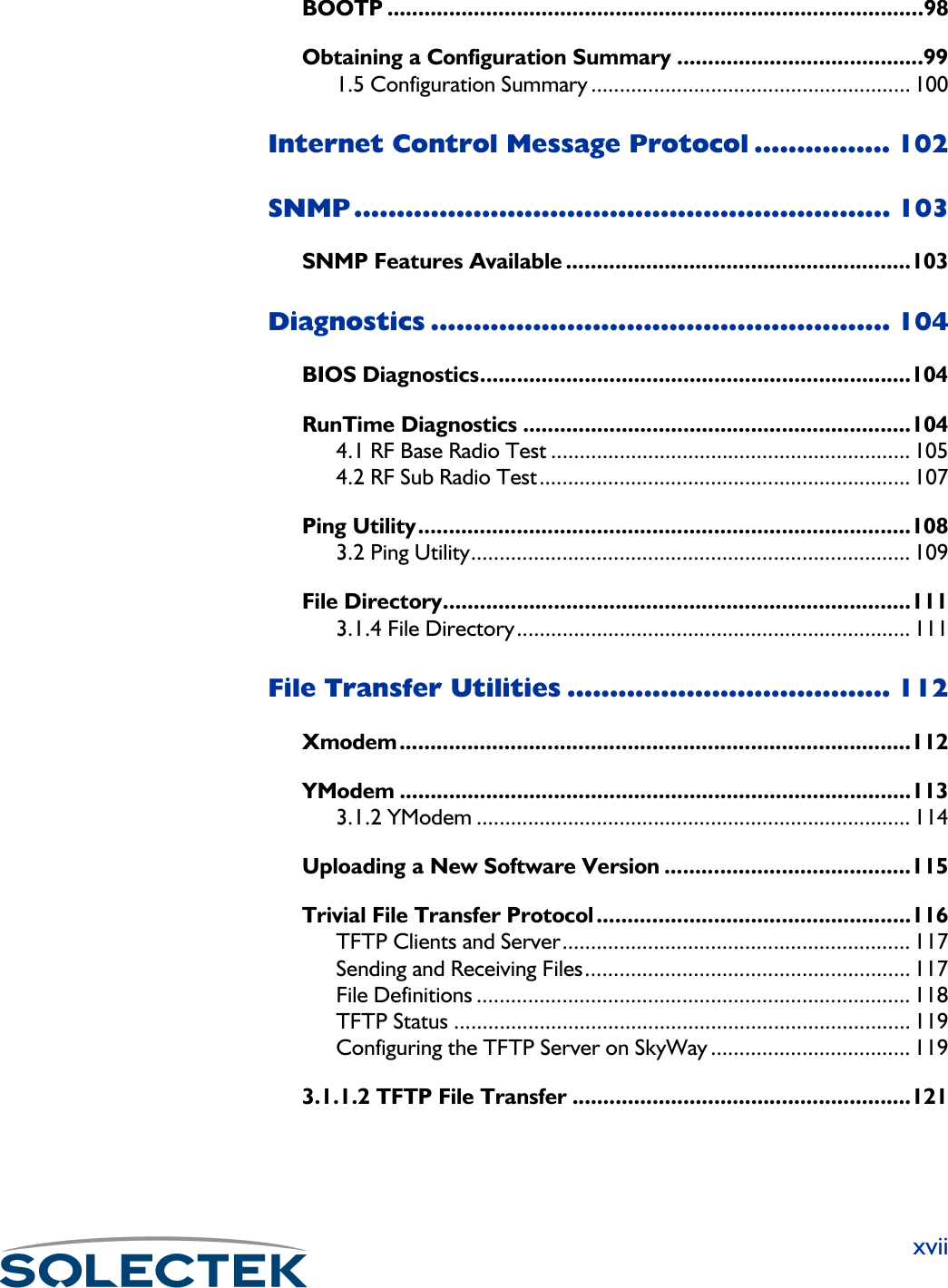
![IP Routing99Obtaining a Configuration SummaryUse screen 1.5 Configuration Summary to check system, port, bridging, routing, and RF port configuration settings.Field Name MIB Settings (default in bold)Relaying [swBootpCfgRelayAgen-tEnabled]•Enabled•••• DisabledDisabledDisabledDisabledSet this field to Enabled to enable BOOTP functionality.Destination Address [swBootpCfgRelayAgent-ForwardIpAddr]255.255.255.255This is the server’s IP address. The default is the limited broadcast address.Maximum Hops [swBootpCfgRelayAgent-MaxHops]4This field sets the maximum number of times a BOOTP request can be routed. The range is 1 - 16.Broadcast Reply [swBootpCfgRelayAgent-BroadcastReplyFlg]••••NoNoNoNo•YesThis field, if set to yes, forces all relayed BOOTP replies to be returned to the client using the limited broadcast IP address.](https://usermanual.wiki/Solectek/24WAN5.Soletek-Skyway-Final-User-Guide/User-Guide-91948-Page-125.png)

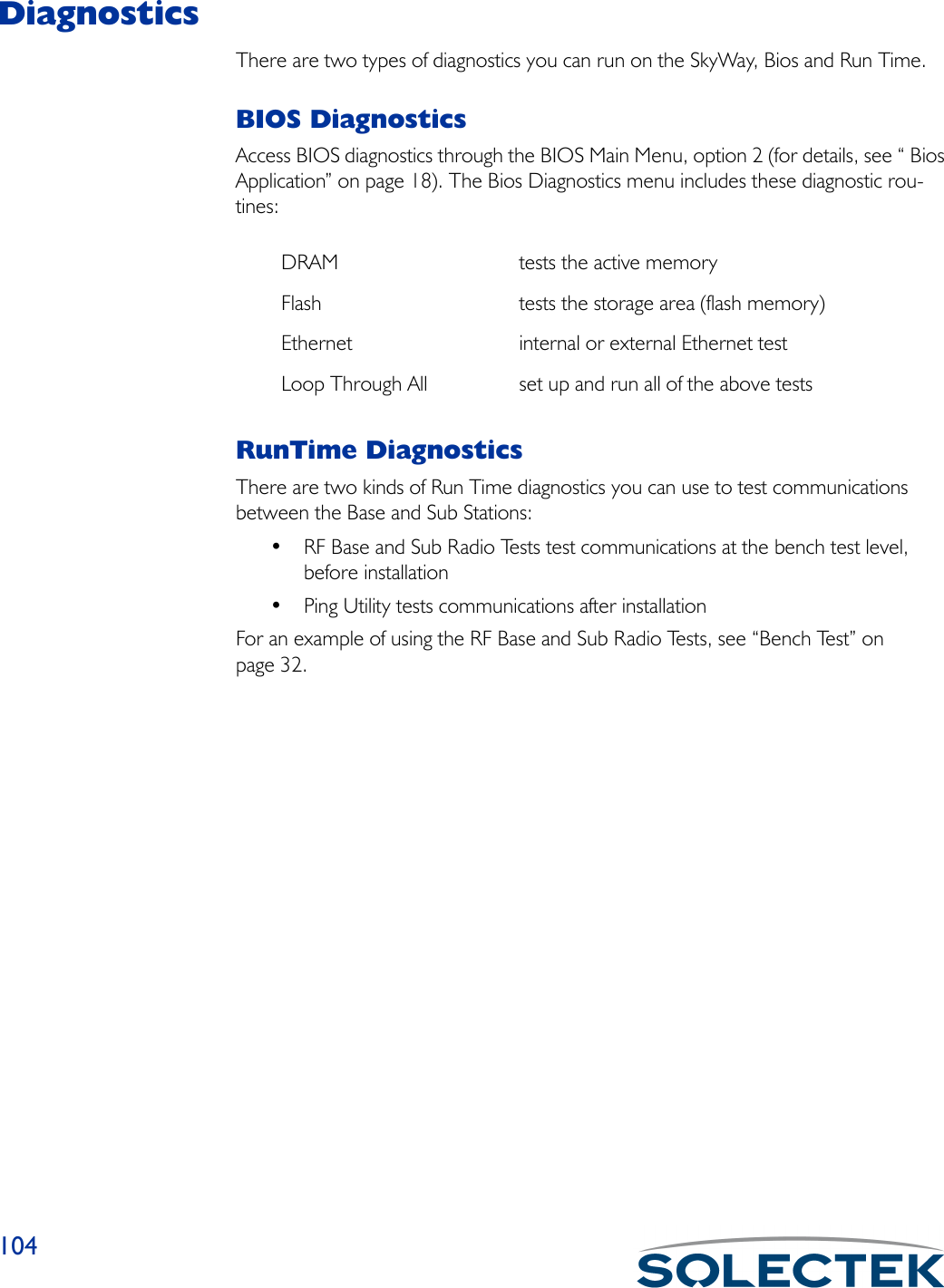
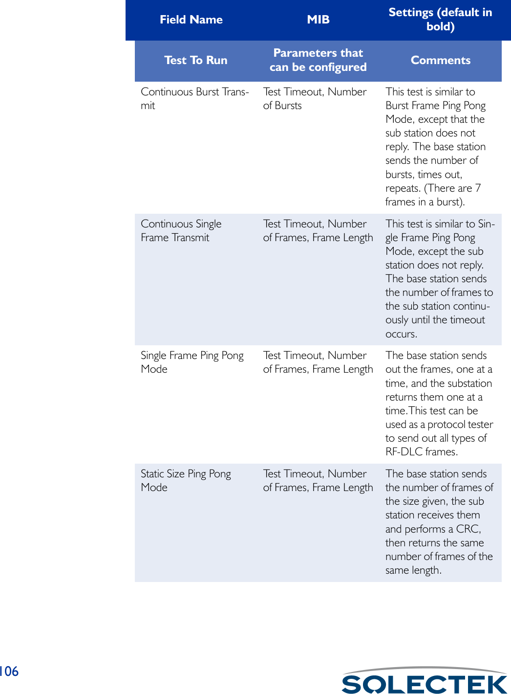
![Diagnostics1054.1 RF Base Radio TestThe following lists the field name, the MIB name, and the default setting:Field Name MIB Settings (default in bold)RF Port Number [swRFBaseTestIndex] 3The RF port number is 3.Te s t T i m e o u t [swRFBaseTestTO] 8The timeout value in milliseconds. This is the amount of time the test will run before terminating on its own.Test to Run: [swRFBaseTestToRun] See the following table:Select a test to run and press .W to begin the test. There are five tests you can run on the base port as described in the following table. To end the test, set Test to Run t o Te r m i n a t e Te s t a n d p r e s s .W.Te s t To R u n Parameters that can be configured CommentsBurst Frame Ping Pong ModeTest Timeout, Number of Bursts, Maximum Burst SizeThe base station sends the specified number of bursts, and the sub sta-tion returns the same number. 4.1 RF Base Radio Test ** Note - diagnostic driver must be installed ** RF Port Number : 3 Test Timeout : 8 milliseconds Test To Run : Terminate Test Number of Frames or Bursts, 1 - 65535 or 0 for Continuous. :0 Frame Length or Maximum Burst Size, 3 - 3200 :1530\ - return to menu . - commands TAB - next available field ENTER - edit](https://usermanual.wiki/Solectek/24WAN5.Soletek-Skyway-Final-User-Guide/User-Guide-91948-Page-131.png)
![Diagnostics1074.2 RF Sub Radio TestThe following lists the field name, the MIB name, and the default setting:Te r m i n a t e Te s t Ends the currently run-ning test.Number of Frames or Bursts[swRFBaseTestFrames] 0The number of frames or bursts to transmit when running the Continuous Single Frame Transmit test.Frame Length or Maxi-mum Burst Size[swRFBaseTestFrame-Length]1530The frame length to transmit when running the Continuous Single Frame Transmit test. The range is 3 to 3200.Field Name MIB Settings (default in bold)RF Port Number [swRFSubTestIndex] 3The RF Port number is 3.Field Name MIB Settings (default in bold)4.2 RF Sub Radio Test ** Note - diagnostic driver must be installed ** RF Port Number : 3 Test To Run : Terminate Test\ - return to menu . - commands TAB - next available field ENTER - edit](https://usermanual.wiki/Solectek/24WAN5.Soletek-Skyway-Final-User-Guide/User-Guide-91948-Page-133.png)
![108Ping UtilityThe Ping utility tests communications between units in a system that is already opera-tional. Ping generates an ICMP Echo Request packet and expects to receive an ICMP Echo Reply packet.Te s t t o R u n [swRFSubTestToRun] • Burst Frame Ping Pong Mode• Continuous Burst Receive• Continuous Single Frame Receive• Single Frame Ping Pong Mode• Static Size Ping Pong ModeNote: Note: Note: Note: See “4.1 RF Base Radio Test” on page 105 for test descriptions.Field Name MIB Settings (default in bold)](https://usermanual.wiki/Solectek/24WAN5.Soletek-Skyway-Final-User-Guide/User-Guide-91948-Page-134.png)
![Diagnostics1093.2 Ping UtilityThe following table lists the field name, the MIB name, and field options with the default setting, if any, in bold:Field Name MIB Settings (default in bold)Destination IP Address [swPingDestIPAddr]The IP address of the unit you want to send an ICMP Echo Request to.Ping Payload Size [swPingPacketSize] 64646464The ping packet size.Number of Packets [swPingNumPackets] 0The number of packets to be sent during the ping session or operation.Reply Timeout [swPingReplyTimeout] 1The number of seconds to wait before this ping session times out.Delay Between Packets [swPingDelay] 0The delay in milliseconds between each ping sent out during this ping session.Ping Operation [swPingOperation] •Start Ping•Abort PingStarts or stops the ping operation.3.2. Ping Utility Destination IP Address : 000.000.000.000 Ping Payload Size : 64 Number of Packets : 0 Reply Timeout : 1 Delay Between Packets : 0 Ping Operation : Start Ping Ping Session Status : Idle Packets Sent : 0 Correct Responses Received : 0 Incorrect Responses Received : 0 Number of Timed Out Packets : 0 Longest Round Trip Delay : 0 Shortest Round Trip Delay : 0 Average Round Trip Delay : 0\ - return to menu . - commands TAB - next available field ENTER - edit](https://usermanual.wiki/Solectek/24WAN5.Soletek-Skyway-Final-User-Guide/User-Guide-91948-Page-135.png)
![110Ping Session Status [swPingStatus] • Idle•PingingThe current status of the last ping session started. Pinging indicates the session is operating, and Idle indicates the last session has finished or no session has been started.Packets Sent [swPingPacketsSent] 0Total number of packets or pings sent in this session.Correct Responses Received[swPingCorrectRR] 0Total number of correct ping responses received.Incorrect Responses Received[swPingIncorrectRR] 0Total number of incorrect ping responses received.Number of Timed Out Packets[swPingNumPacketsTim-eout]0The number of packets that timed out during this ping session.Longest Round Trip Delay [swPingLongestRTD] 0The longest round trip delay. The amount of time in milliseconds that has passed between the time the ping was sent and the response for that ping is returned.Shortest Round Trip Delay[swPingShortestRTD] 0The shortest round trip delay. The amount of time in milliseconds that has passed between the time the ping was sent and the response for that ping is returned.Average Round Trip Delay[swPingAverageRTD] 0The average round trip delay. The amount of time in milliseconds that has passed between the time the ping was sent and the response for that ping is returned.Field Name MIB Settings (default in bold)](https://usermanual.wiki/Solectek/24WAN5.Soletek-Skyway-Final-User-Guide/User-Guide-91948-Page-136.png)
![1143.1.2 YModemThe following table lists the field name, the MIB name, and the default setting:Field Name MIB Settings (default in bold)Port Number [swXmodemIFIndex][swYmodemIFIndex]1The port number is 1, the serial port.File Type [swXmodemFileType][swYmodemFileType]•Boot loader•FGPA•Crash dump• Error log• Bios data base•Saved data base• Default data base• Boot Application• Runtime ApplicationThe type of file to be transferred.Session Type [swXmodemAction][swYmodemAction]Send/ReceiveThe action to be performed by the file transfer task, Download (Send), or Upload (Receive).3.1.2. Ymodem File Transfer Port Number : 1 File Type : Runtime Application Session Type : Choose Action File Name : Status : Idle Bytes Transferred : 0 Number of Retries : 0 Error Message :\ - return to menu . - commands TAB - next available field ENTER - edit](https://usermanual.wiki/Solectek/24WAN5.Soletek-Skyway-Final-User-Guide/User-Guide-91948-Page-140.png)
![File Transfer Utilities115Uploading a New Software VersionThis procedure describes how to upload a new software version to the SkyWay Bridge/Router, and assumes you are running the SkyWay Administrative Console in a HyperTerminal window using the Ymodem protocol.1. From the SkyWay main menu, go to screen 3.1.2 - Ymodem File Transfer.Note Follow steps 2 and 3, even if the screen appears to have the correct values, or the file transfer might not take place properly.2. Enter the following values in the fields:Port Number: 1 (this is non-configurable, 1 is the serial port).File Type: Runtime ApplicationFile Name [swYmodemFileName]The file name of the file to be transferred. The Xmodem screen does not have the File Name field.Status [swXmodemStatus][swYmodemStatus]•Receiving•Transmitting• Failed•IdleThe current status of this file transfer.Bytes Transferred [swXmodemBytesTrans-ferred][swYmodemBytesTrans-ferred]0 – 4,294,967,295Counts the number of bytes as the file is currently being transferred and dynamically displays it. If there is not a current transfer running, the number of bytes transferred in the last file transfer is displayed.Number of Retries [swXmodemNumRe-tries][swYmodemNumRetries]0 – 4,294,967,295 (only after an error)The number of retries for the current or last file transfer.Error MessageA text message which displays the reason the file transfer failed.Field Name MIB Settings (default in bold)](https://usermanual.wiki/Solectek/24WAN5.Soletek-Skyway-Final-User-Guide/User-Guide-91948-Page-141.png)
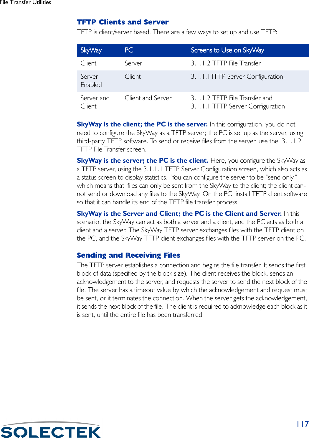
![File Transfer Utilities119TFTP StatusThe 3.1.1.1 TFTP Server Configuration screen is also a status screen that provides information about the current or last file transfer that occurred on the SkyWay TFTP server.Configuring the TFTP Server on SkyWayUse 3.1.1.1 TFTP Server Configuration screen to set up the SkyWay as a TFTP Server.3.1.1.1 TFTP Server ConfigurationThe following table lists the field name, MIB, and the settings (default in bold):Field Name MIB Settings (default in bold)Server Status [swTFTPServerStatus] • Enabled•Send only•••• DisabledDisabledDisabledDisabledSet Server Status to Enabled or Send only to configure the SkyWay as a TFTP server. Send only means the TFTP server is enabled to send files only and cannot receive files.Time_out [swTFTPServerTO] 20The amount of time in seconds the TFTP Server will wait before a timeout occurs. For example, if the server sends a packet and it is not acknowledged by the client before the timeout expires, the server shuts down the connection. 3.1.1.1 TFTP Server Configuration Server Status : Disabled Time_out : 20 Current State : Idle Current File : Use Filename Read Requests : 0 Write Requests : 0 Aborted Sessions : 0 Reset Statistics : No\ - return to menu . - commands TAB - next available field ENTER - edit](https://usermanual.wiki/Solectek/24WAN5.Soletek-Skyway-Final-User-Guide/User-Guide-91948-Page-145.png)
![120Current State [swTFTPServerState] • Receiving•Sending••••IdleIdleIdleIdleThe current status of the TFTP Server.Current File [swTFTPServerFile] Use filenameThe type of file currently being transferred. Read Requests [swTFTPServerRRQ]Number of read requests received by the TFTP Server.Write requests [swTFTPServerWRQ]Number of write requests received by the TFTP Server.Aborted Sessions [swTFTPServerAborts]The number of times an upload was aborted since the last reboot.Reset Statistics [swTFTPServerStatsRe-set]•Yes••••NoNoNoNoReset the statistics each time a file transfer is started.Field Name MIB Settings (default in bold)](https://usermanual.wiki/Solectek/24WAN5.Soletek-Skyway-Final-User-Guide/User-Guide-91948-Page-146.png)
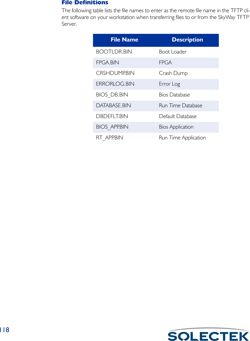
![File Transfer Utilities1213.1.1.2 TFTP File TransferThe following table lists the field name, the MIB name, and the default setting:Field Name MIB Settings (default in bold)IP Host Address [swTFTPIPAddr] 000.000.000.000This is the IP address of the PC that is running the server.File Type [swTFTPFileType] •Boot loader•FGPA•Crash dump• Error log• Bios data base•Saved data base• Default data base• Boot Application• Runtime Application•Use FilenameThe type of file to be transferred.File Name [swTFTPFileName]The file name of the file to be transferred.Timeout [swTFTPTO] 20Tells the server what the timeout parameter will be, that is, how long the server should wait to receive an acknowledgement before terminating the connection. 3.1.1.2. TFTP File Transfer IP Host Address : 000.000.000.000 File Type : Runtime Application File Name : Timeout : 20 Block Size : 512 Session Type : Receive Status : Idle Bytes Transferred : 0 Number of Retries : 0 Error Message :\ - return to menu . - commands TAB - next available field ENTER - edit](https://usermanual.wiki/Solectek/24WAN5.Soletek-Skyway-Final-User-Guide/User-Guide-91948-Page-147.png)
![122Block Size [swTFTPBlockSize] 512The amount of data that is sent over at one time (80-1400 bytes).Session Type [swTFTPAction] •Receive•Send••••AbortAbortAbortAbortThe action to be performed by the client, that is, either send a file to the server or receive a file from the server.Status [swTFTPStatus] • Receiving•Transmitting• Failed••••IdleIdleIdleIdleThe current status of the transfer.Bytes Transferred [swTFTPBytesTrans-ferred]0Counts the number of bytes as the file is currently being transferred and dynamically displays it. If a file isn’t currently transferring, this field displays the number of bytes transferred in the last file transfer.Number of Retries [swTFTPNumRetries] 0 (only after an error)The number of retries for the current or last file transfer.Error Message [swTFTPErrMsg]A text message which displays the reason the file transfer failed.Field Name MIB Settings (default in bold)](https://usermanual.wiki/Solectek/24WAN5.Soletek-Skyway-Final-User-Guide/User-Guide-91948-Page-148.png)
![System Status and Control Screens1292.1.2.2 SNMP Trap HistoryThis screen displays the trap number, description, value (OID), and date and time the error occured.)Field Name MIB CommentsTr a p # [ s w Tr a p H i s t o r y I n d e x ]A number that corresponds to the trap log table index.Trap Description [swTrapHistoryName]A description of the type of trap that occurred. For a list of trap messages, see “Appendix G: SNMP Trap Messages” on page 191.Value [swTrapHistoryValue]The value of the first trap variable or zero.Date & Time [swTrapHistoryDateAnd-Time]The date and time the trap occurred. 2.1.2.2. SNMP Trap History Record 1 of 6 Trap# Trap Description Value Date & Time ----- -------------------------------- ----- --------------------- 0 Link_Down 2 02 Mar 1999 21:58:45 1 New_Root 0 02 Mar 1999 21:58:45 2 New_Root 0 02 Mar 1999 21:58:45 3 Link_Up 8 02 Mar 1999 21:58:45 4 Link_Down 3 02 Mar 1999 21:58:45 5 Link_Up 8 02 Mar 1999 21:58:45 \ - return to menu . - commands TAB - next available field ENTER - edit](https://usermanual.wiki/Solectek/24WAN5.Soletek-Skyway-Final-User-Guide/User-Guide-91948-Page-155.png)
![System Status and Control Screens130Checking the Error LogUse the 2.1.3 Error Log Status screen to check the error log.Field Name MIB CommentsEr# [swErrorLogIndex]The number of the error corresponding to the error log index.Partial Error Description [swErrorLogEntry]The first 40 characters of the error description.Log Level [swErrorLogLevel] • Notification•Warning•Recoverable•FatalThe severity of the error. Notification is informational, Warning indicates there may be a possible problem, Recoverable is an error, but indicates the system is still func-tional, and Fatal is an error indicating an unstable system or a crash.Date & Time [swErrorLogDateAnd-Time]The date and time the error occurred. 2.1.3. Error Log Screen Record 1 of 14 Er# Partial Error Description Log Level Date & Time --- ---------------------------------------- ------------ --------------------- 0 Link Up Trap for port 1 Notification 14 Jan 2001 20:44:19 1 Link Up Trap for port 2 Notification 14 Jan 2001 20:44:19 2 Cold Start Trap Notification 14 Jan 2001 20:44:50 3 Link Down Trap for port 2 Notification 14 Jan 2001 20:46:44 4 New root detected. Notification 14 Jan 2001 20:46:44 5 New root detected. Notification 14 Jan 2001 20:46:45 6 Link Up Trap for port 2 Notification 14 Jan 2001 20:46:45 7 Link Up Trap for port 3 Notification 14 Jan 2001 20:47:20 8 Link Down Trap for port 2 Notification 14 Jan 2001 21:12:13 9 New root detected. Notification 14 Jan 2001 21:12:13 10 New root detected. Notification 14 Jan 2001 21:12:13 11 Link Up Trap for port 2 Notification 14 Jan 2001 21:12:13 12 Link Down Trap for port 3 Notification 14 Jan 2001 23:24:13 13 Link Up Trap for port 3 Notification 14 Jan 2001 23:24:18 Link Up Trap for port 1 File: up_port.c Line: 355 TrapOid: 4\ - return to menu . - commands TAB - next available field ENTER - edit](https://usermanual.wiki/Solectek/24WAN5.Soletek-Skyway-Final-User-Guide/User-Guide-91948-Page-156.png)
![System Status and Control Screens131Error message at the bot-tom of the screen[swErrorLogEntry]A more complete description of the error at the cursor position.File: [swErrorLogFileName]The source file where the error occurred.Line: [swErrorLogLineNum-ber]The line of code in the source file where the error occurred.Tr a p O i d : [swErrorLogTrapOid]The Trap Object Identifier (OID).Field Name MIB Comments](https://usermanual.wiki/Solectek/24WAN5.Soletek-Skyway-Final-User-Guide/User-Guide-91948-Page-157.png)
![Port Status and Control Screens132Port Status and Control ScreensThe Port Status and Control screens allow you to check the status of the following:• Serial port• Ethernet port• Ethernet Transceiver•RF PortsChecking the Serial Port StatusUse the 2.2.2 Serial Port Status screen to check serial port parameters and errors,2.2.2 Serial Port StatusField Name MIBPort Number [rs232AsyncPortIndex] 1The serial port number is 1.Data Bits [rs232AsyncPortBits]The number of bits in a character.Parity [rs232AsyncPortParity]The port’s sense of a character parity bit.Stop Bits [rs232AsyncPortStopBits] 2.2.2. Serial Port Status Port Number : 0 Data Bits : 8 Parity : NONE Stop Bits : 1 Parity Errors : 0 Framing Errors : 0 Overrun Errors : 0 \ - return to menu . - commands TAB - next available field ENTER - edit](https://usermanual.wiki/Solectek/24WAN5.Soletek-Skyway-Final-User-Guide/User-Guide-91948-Page-158.png)
![Port Status and Control Screens133The number of stop bits.Parity Errors [rs232AsyncPortParityErrs]The total number of characters with a parity error, input from the port since system re-initialization and while the port state was “up” or “test”.Framing Errors [rs232AsyncPortFramingErrs]The total number of characters with a framing error, input from the port since sys-tem re-initialization and while the port state was “up” or “test”.Overrun Errors [rs232AsyncPortOverrunErrs]The total number of characters with an overrun error, input from the port since sys-tem re-initialization and while the port state was “up” or “test”.Field Name MIB](https://usermanual.wiki/Solectek/24WAN5.Soletek-Skyway-Final-User-Guide/User-Guide-91948-Page-159.png)
![Port Status and Control Screens134Checking the Ethernet Port StatusFrom the 2.2.3 Ethernet Port Status menu, you can check how many times Ethernet Port errors or conditions occurred, and the status of the Ethernet Transceiver.2.2.3.1 Ethernet Port StatusField Name MIB 2Port Number [dot3StatsIndex]The physical port number is 2.Alignment Errors [dot3StatsAlignmentErrors]The number of frames received on a particular interface that are not an integral number of octets in length and do not pass the FCS check.FCS Errors [dot3StatsFCSErrors]The number of frames received on a particular interface that are an integral number of octets in length but do not pass the FCS check.Single Collision Frames [dot3StatsSingleCollisionFrames]The number of successfully transmitted frames on a particular interface for which transmission is inhibited by exactly one collision 2.2.3.1. Ethernet Port Status Record 1 of 1 Port Number : 2 Alignment Errors : 0 FCS Errors : 0 Single Collisions : 0 Multiple Collisions : 0 SQE Test Errors : 0 Frames Deferred : 0 Late Collisions : 0 Excessive Collisions : 0 Internal MAC Transmit Errors : 0 Carrier Sense Lost : 0 Frames Too Long : 0 Internal MAC Receive Errors : 0\ - return to menu . - commands TAB - next available field ENTER - edit](https://usermanual.wiki/Solectek/24WAN5.Soletek-Skyway-Final-User-Guide/User-Guide-91948-Page-160.png)
![Port Status and Control Screens135Multiple Collision Frames [dot3StatsMultipleCollisionFrames]The number of successfully transmitted frames on a particular interface for which transmission is inhibited by more than one collision.SQE Test Errors [dot3StatsSQETestErrors]The number of times that the SQE TEST ERROR message is generated by the PLS sublayer for a particular interface.Deferred Transmissions [dot3StatsDeferredTransmissions]The number of frames which experience a delay for the first transmission attempt on a particular interface because the medium is busy.Late Collisions [dot3StatsLateCollisions]The number of times a collision is detected on a particular interface later than 512 bit-times into the transmission of a packet.Excessive Collisions [dot3StatsExcessiveCollisions]The number of frames which could not be transmitted on a particular interface due to excessive collisions.Internal MAC Transmit Errors[dot3StatsInternalMacTransmitErrors]The number of frames which could not be transmitted on a particular interface due to an internal MAC sublayer transmit error.Carrier Sense Lost [dot3StatsCarrierSenseErrors]The number of times that the carrier sense condition was lost or never asserted when attempting to transmit a frame on a particular interface.Frames Too Long [dot3StatsFrameTooLongs]The number of frames received on a particular interface that exceed the maximum permitted frame size.Internal MAC Receive Errors[dot3StatsInternalMacReceiveErrors]The number of frames for which reception on a particular interface fails due to an internal MAC sublayer receive error.Field Name MIB 2](https://usermanual.wiki/Solectek/24WAN5.Soletek-Skyway-Final-User-Guide/User-Guide-91948-Page-161.png)
![Port Status and Control Screens1362.2.3.2 Ethernet Transceiver StatusField Name MIB CommentsPort Number [swEtherTransStatusIn-dex]2The Ethernet port number is 2.Link Status [swEtherTransLinkStatus]Tells you if the link is up or down.Chip Speed [swEtherTransSpeedSta-tus]If you have the Ethernet transceiver set to auto-negotiate the chip speed, this tells you at what speed it actually came up.Duplex Mode [swEtherTransDuplexSta-tus]Displays the configuration status of the Transceiver at either full or half duplex mode. 2.2.3.2. Ethernet Transceiver Status Record 1 of 1 Port Link Chip Duplex Number Status Speed Mode ------ ------ ----- ------ 2 Up 10 Mbps Half Duplex\ - return to menu . - commands TAB - next available field ENTER - edi](https://usermanual.wiki/Solectek/24WAN5.Soletek-Skyway-Final-User-Guide/User-Guide-91948-Page-162.png)
![Port Status and Control Screens137Checking the RF PortUse the 2.2.4 RF Port Status screen to list RF ports and monitor link statistics. The screen displays the information and statistics for a given port.2.2.4 RF Port StatusField Name MIB CommentsPort Number [swRFPortIndex] 3RF physical port number.Port Type [swRFPortType] •Base Port•Sub Port•Base Port Diag•Sub Port DiagThe type of port (driver) this status is displaying.Port Status [swRFPortStatus] • On-line• Off-lineThe operational status of the port.RF data rate [swRFPortBW] •2 Mbs• 5.5 Mbs• 11 MbsThe RF data rate for this port. 2.2.4. RF Port Status Record 1 of 1 Port Number : 3 Port Type : RF Base Port Port Status : Online RF data rate : 5.5 Mbps RF Channel : 2414 Mhz Bytes IN : 0 Bytes OUT : 2703 Frames IN : 749 Frames OUT : 901 Discards IN : 0 Discards OUT : 0 Digital Phase Lock Loop : 0 Frame Length Violation : 0 Non Octet Aligned Frame : 0 Abort Sequence : 0 CRC error : 0 Overrun : 0 Carrier Detect Lost : 0 Underrun : 0 CTS Lost : 0\ - return to menu . - commands TAB - next available field ENTER - edit](https://usermanual.wiki/Solectek/24WAN5.Soletek-Skyway-Final-User-Guide/User-Guide-91948-Page-163.png)
![Port Status and Control Screens138RF Channel [swRFPortChannel]]The channel frequency in MHz.Bytes IN and OUT [swRFPortInBytes] and [swRFPortOutBytes]The total number of incoming and outgoing bytes on this port.Frames IN and OUT [swRFPortInFrames] and[swRFPortOutFrames]The total number of incoming and outgoing frames on this port.Discards IN and OUT [swRFPortInDiscards] and [swRFPortOutDiscards]The total number of incoming and outgoing discarded frames (for any reason) on this port.Digital Phase Lock Loop [swRFPortDPLLErrors]The number of Digital Phase Lock Loop error that occurred on this port.Frame Length Violation [swRFPortFrameLength-Errors]The total number of frames with Frame Length Error received on this port.Non Octet Aligned Frame [swRFPortFrameAlign-mentErrors]The total number of Framing Alignment errors on the port.Abort Sequence [swRFPortAbortErrors]The total number of RF frames aborted for any reason on the port.CRC Error [swRFPortCRCErrors]The total number of CRC errors on the port.Overrun [swRFPortOverrunErrors] Reception errorThe number of buffer overflows for this port. Carrier Detect Lost [swRFPortCarrier Detect-Lost]Reception errorThe number of times carrier detect was lost.Field Name MIB Comments](https://usermanual.wiki/Solectek/24WAN5.Soletek-Skyway-Final-User-Guide/User-Guide-91948-Page-164.png)
![Port Status and Control Screens139Underrun [swRFPortUnderrunEr-rors]Transmission errorThe number of incomplete buffer errors in the communication processor for the port.CTS Lost [swRFPortCTSLost] Transmission errorThe number of times clear to send was lost for the port.Field Name MIB Comments](https://usermanual.wiki/Solectek/24WAN5.Soletek-Skyway-Final-User-Guide/User-Guide-91948-Page-165.png)
![RF-DLC Screens140RF-DLC ScreensUse these screens to monitor the status of RF-DLC Base and Sub ports. They provide information about frames sent and received, port states, events, actions, etc. The screens in this section are all read-only.Note The base station sends commands to the sub station and receives responses from the sub station.Checking RF-DLC Base Port StatusThe 2.5.1 RF-DLC Base Port Status screen displays statistics that show the number of frames transmitted or received as a response from all sub stations. On the base station, this screen shows a summary of activity from all the sub stations. On sub stations, the values all will be zero.2.5.1 RF-DLC Base Port StatusField Name MIB CommentsPort No. [swRFDLCBasePortIn-dex]3This is the physical RF port. 2.5.1. RF-DLC Base Port Status Record 1 of 1 Prt SNRME FRMR IFrames RR No. TX REC TX REC --- ---------- ---------- ---------- ---------- ---------- ---------- 3 4 0 127 655 120654 120434 REJ TX 10 UA 2 REJ REC 0 DISC 0 RNR TX 0 UI TX 0 XID TX 1 RD 0 RNR REC 0 UI REC 0 XID REC 1 DM 0 \ - return to menu . - commands TAB - next available field ENTER - edit](https://usermanual.wiki/Solectek/24WAN5.Soletek-Skyway-Final-User-Guide/User-Guide-91948-Page-166.png)
![RF-DLC Screens141SNRME [swRFDLCBasePortSN-RME]The number of Set Normal Response Mode Extended (SNRME) commands sent to all sub stations. A UA is the expected response.FRMR [swRFDLCBasePort-FRMR]The number of Frame reject responses sent from the sub station when it receives an invalid frame.IFrames TX [swRFDLCBase-PortOutIFrame]The number of IFrames transmitted.IFrames REC [swRFDLCBasePortInI-Frame]The number of IFrames received.RR - TX [swRFDLCBase-PortOutRR]The number of Receive ready commands sent to all sub stations.RR - REC [swRFDLCBasePort-INRR]The number of Receive ready responses received from all sub stations.REJ TX [swRFDLCBase-PortOutREJ]The number of Reject commands sent to all sub stations.REJ REC [swRFDLCBasePortInREJ]The number of Reject responses received from all sub stations.RNR TX [swRFDLCBase-PortOutRNR]The number of Receive not ready commands sent to all sub stations.RNR REC [swRFDLCBasePortIn-RNR]The number of Receive not ready responses received from all sub stations.Field Name MIB Comments](https://usermanual.wiki/Solectek/24WAN5.Soletek-Skyway-Final-User-Guide/User-Guide-91948-Page-167.png)
![RF-DLC Screens142UI TX [swRFDLCBasePortOu-tUI]The number of Unnumbered information commands sent to all sub stations.UI REC [swRFDLCBasePortInUI]The number of Unnumbered information responses received from all sub stations.XID TX [swRFDLCBase-PortOutXID]The number of Exchange station identification commands sent to all sub stations.XID REC [swRFDLCBasePort-InXID]The number of Exchange station identification responses received from all sub sta-tions.UA [swRFDLCBasePortUA]The number of Unnumbered acknowledgement responses received from the sub station.DISC [swRFDLCBasePort-DISC]The number of Disconnect commands sent to all sub stations.RD [swRFDLCBasePortRD]The number of Request disconnect responses received from all sub stations.DM [swRFDLCBasePortDM]The number of Disconnect mode responses received from all sub stations.Field Name MIB Comments](https://usermanual.wiki/Solectek/24WAN5.Soletek-Skyway-Final-User-Guide/User-Guide-91948-Page-168.png)
![RF-DLC Screens143Checking the Sub Port StatusYou can access the 2.5.2 RF-DLC Sub Port Status screen on either the base station or the sub station. On the base station, this screen shows the status of all the base sub ports (sub station numbers). On the sub station, this screen shows the status of that sub station.2.5.2 RF-DLC Sub Port StatusField Name MIB CommentsPort No. [swRFDLCSubPortIndex]This is the physical RF port or sub station number.SNRME [swRFDLCSubPortSN-RME]The number of Set normal response mode extended (SNRME) commands sent to the sub station. A UA is the expected response.FRMR [swRFDLCSubPortFRMR]The number of Frame reject responses sent from the sub station when it receives an invalid frame.IFrames TX [swRFDLCSub-PortOutIFrame]The number of IFrames transmitted. 2.5.2. RF-DLC Sub Port Status Record 1 of 1Prt SNRME FRMR IFrames RR StateNo. TX REC TX REC--- ---------- ---------- ---------- ---------- ---------- ---------- -----3 4 0 655 127 120434 120654 NRM REJ TX 0 UA 2 REJ REC 10 DISC 0 RNR TX 0 UI TX 0 XID TX 1 RD 0 RNR REC 0 UI REC 0 XID REC 1 DM 0\ - return to menu . - commands TAB - next available field ENTER - edit](https://usermanual.wiki/Solectek/24WAN5.Soletek-Skyway-Final-User-Guide/User-Guide-91948-Page-169.png)
![RF-DLC Screens144IFrames REC [swRFDLCSubPortInI-Frame]The number of IFrames received.RR - TX [swRFDLCSub-PortOutRR]The number of Receive ready commands sent to the sub station.RR - REC [swRFDLCSubPortINRR]The number of Receive ready responses received from the sub station.State [swRFDLCSubPortState] •ADP•NRM•NRM-W•NDM•NRDThe current state of the connection with the sub to the base. ADP is Automatic Dis-covery Protocol, NRM is Normal Response Mode, NRM-W is Normal Response Mode-Waiting, NDM is Normal Disconnect Mode, and NRD is Normal Request Disconnect.REJ TX [swRFDLCSub-PortOutREJ]The number of Reject commands sent to the sub station.REJ REC [swRFDLCSubPortInREJ]The number of Reject responses received from the sub station.RNR TX [swRFDLCSub-PortOutRNR]The number of Receive not ready commands sent to the sub station.RNR REC [swRFDLCSubPortIn-RNR]The number of Receive not ready responses received from the sub station.UI TX [swRFDLCSubPortOu-tUI]The number of Unnumbered information commands sent to the sub station.UI REC [swRFDLCSubPortInUI]The number of Unnumbered information responses received from the sub station.Field Name MIB Comments](https://usermanual.wiki/Solectek/24WAN5.Soletek-Skyway-Final-User-Guide/User-Guide-91948-Page-170.png)
![RF-DLC Screens145XID TX [swRFDLCSub-PortOutXID]The number of Exchange station identification commands sent to the sub station.XID REC [swRFDLCSubPortInXID]The number of Exchange station identification responses received from the sub sta-tion.UA [swRFDLCSubPortUA]The number of Unnumbered acknowledgement responses received from the sub station.DISC [swRFDLCSubPortDISC]The number of Disconnect commands sent to the sub station.RD [swRFDLCSubPortRD]The number of Request disconnect reponses received from the sub station.DM [swRFDLCSubPortDM]The number of Disconnect mode responses received from the sub station.Field Name MIB Comments](https://usermanual.wiki/Solectek/24WAN5.Soletek-Skyway-Final-User-Guide/User-Guide-91948-Page-171.png)
![RF-DLC Screens147Checking the RF Signal StatusYou can check the RF signal status for the RF Base Sub Ports.2.5.4 RF Signal StatusField Name MIB CommentsPort Number [swSignalStatusIndex]The port number of the unit for which you are viewing this status.Signal Level (-dBm) [swSignalStatusSig-nalLevel]]The detected signal level for this port. For example, a value of 55 is -55 dBm.Noise Level (-dBm) [swSignalStatus-NoiseLevel]The detected noise level for this port. For example, a value of 85 is -85 dBm. A value of 95 is no noise detected.Signal/Noise (dB) [swSignalStatusSignal-To N o i s e ]The signal to noise ratio. The value indicates Noise Level minus Signal Level. 2.5.4. RF-DLC Signal Status Record 0 of 0 Signal NoisePort Level (-dBm) Level (-dBm) Signal/Noise (dB) Rcv Timeouts/Sec---- ------------ ------------ ----------------- ----------------256 95 95 0 0\ - return to menu . - commands TAB - next available field ENTER - edit](https://usermanual.wiki/Solectek/24WAN5.Soletek-Skyway-Final-User-Guide/User-Guide-91948-Page-173.png)
![RF-DLC Screens148Rcv Timeouts/Sec [swSignalStatusRcvToR-ate]The rate of receiver timeouts.Field Name MIB Comments](https://usermanual.wiki/Solectek/24WAN5.Soletek-Skyway-Final-User-Guide/User-Guide-91948-Page-174.png)
![Bridging Screens149Bridging ScreensChecking Bridge and Spanning Tree StatusThe 2.3.1 Bridge and Spanning Tree Status screen is divided into two parts:• Bridge Status shows you the bridge settings• (If Spanning Tree is enabled) Spanning Tree Status shows you the settings for the Spanning Tree.2.3.1 Bridge and Spanning Tree StatusField Name MIB CommentsBridge Status:Bridge Status:Bridge Status:Bridge Status:Bridge MAC Address [dot1dBaseBridgeAddress]The MAC address used by the bridge as its unique identifier. The bridge MAC Address concatenated with Bridge Priority creates a unique Bridge ID which the Spanning Tree Protocol uses.Number of Bridge Ports [dot1dBaseNumPorts]Minimum of 2 per unit, the Ethernet and the RF ports. On the base station, the number of bridge ports is equal to one plus the number of base sub ports. 2.3.1. Bridge & Spanning Tree Status Bridge Status ------------- Bridge MAC Address : 00:ba:d0:ba:be:00 Number of Bridge Ports : 2 Bridging Type : Transparent only Spanning Tree Status -------------------- Root ID : 4241 00:ba:d0:ba:be:00 Bridge Priority : 16961 Root Port : 0 Bridge Max Age : 20 Root Cost : 0 Bridge Hello Time : 2 Maximum Age : 20 Bridge Forward Delay : 15 Hello Time : 2 Forward Table Timeout: 300 Hold Time : 1 Forward Delay : 15 Time Since Last Topology Change : 2108 Topology Changes : 1\ - return to menu . - commands TAB - next available field ENTER - edit](https://usermanual.wiki/Solectek/24WAN5.Soletek-Skyway-Final-User-Guide/User-Guide-91948-Page-175.png)
![Bridging Screens150Bridging Type [dot1dBaseType]Currently Transparent only.Spanning Tree Status:Spanning Tree Status:Spanning Tree Status:Spanning Tree Status:Root ID [dot1dStpDesignatedRoot]The bridge identifier of the root of the Spanning Tree. This value is used as the Root Identifier in all Configuration Bridge PDUs originating from this node.Root Port [dot1dStpRootPort]The number of the port offering the lowest cost path from this bridge to the root bridge.Root Cost [dot1dStpRootCost]The cost of the path to the root bridge from this bridge.Maximum Age [dot1dStpMaxAge] This is the actual value the bridge is currently using.The maximum age of Spanning Tree protocol information learned from the network on any port before it is discarded, in seconds.Hello Time [dot1dStpHelloTime] This is the actual value the bridge is currently using.The amount of time between the transmission of Configuration bridge PDUs by this node on any port when it is the root of the Spanning Tree or trying to become so, in seconds.Hold Time [dot1dStpHoldTime]The interval length during which no more than two Configuration bridge PDUs can be transmitted by this node, in hundredths of a second.Forward Delay [dot1dStpForwardDelay] This is the actual value the bridge is currently using.Controls how fast a port changes its spanning state when moving towards the For-warding state. This value determines how long the port stays in each of the Listening and Learning states, which precede the Forwarding state. This value is also used when a topology change has been detected and is underway to age all dynamic entries in the Forwarding database.Bridge Priority [dot1dStpPriority]A value which is concatenated to the Bridge MAC address and the result is the Bridge ID. The Bridge ID is used in the Spanning Tree Protocol.Field Name MIB Comments](https://usermanual.wiki/Solectek/24WAN5.Soletek-Skyway-Final-User-Guide/User-Guide-91948-Page-176.png)
![Bridging Screens151For more information about these configuration settings, see “1.3.1 Bridge Configura-tion” on page 90Bridge Max Age [dot1dStpBridgeMaxAge]The value that all bridges use for Max Age when this bridge is acting as the root.Bridge Hello Time [dot1dStpBridgeHelloTime]The value that all bridges use for Hello Time when this bridge is acting as the root.Bridge Forward Delay [dot1dStpBridgeForwardDelay]The value that all bridges use for Forward Delay when this bridge is acting as the root.Forward Table Timeout [dot1dTpAgingTime]The timeout period in seconds for aging out dynamically learned forwarding infor-mation.Time Since last Topology Change[dot1dStpTimeSinceTopologyChange]The time since the last time a topology change was detected by the bridge entity.Topology Changes [dot1dStpTopologyChanges]The total number of topology changes detected by the bridge since the manage-ment entity was last reset or initialized.Field Name MIB Comments](https://usermanual.wiki/Solectek/24WAN5.Soletek-Skyway-Final-User-Guide/User-Guide-91948-Page-177.png)
![Bridging Screens152Checking Bridge Port StatusUse this screen 2.3.2 Bridge Port Status to monitor frame activity on the bridge port.2.3.2 Bridge Port StatusField Name MIB CommentsPort No. [swBridgePortStatusIn-dex]The physical port number or base sub port (sub station) number. On a sub station, the bridge ports are 2 and 3. On a base station, the bridge ports are 2 and the sub station numbers.Max Info [swBridgePortStatusMax-Info]Maximum size of the information field that this port can transmit or receive.In Frames [swBridgePortStatusIn-Frames]Frames, including bridge management frames, are added into the count only if processed by the bridg-ing function.Total number of frames received on this port. 2.3.2. Bridge Port Status Record 1 of 1 Port Max In Out In MTU Exceeded No. Info Frames Frames Discards Discards ---- ---- ------------- ------------- ------------- ------------- 2 1492 0 0 0 0\ - return to menu . - commands TAB - next available field ENTER - edi](https://usermanual.wiki/Solectek/24WAN5.Soletek-Skyway-Final-User-Guide/User-Guide-91948-Page-178.png)
![Bridging Screens153Out Frames [swBridgePortStatusOut-Frames]Frames, including bridge management frames, are added into the count only if processed by the bridg-ing function.Total number of frames transmitted on this port. In Discards [swBridgePortStatusInDis-cards]In Discards is incremented when a packet comes in on a port that is not forwarding, or is destined for a non-forwarding port.MTU Exceeded Discards [swBridgePortStatusMtu-ExceededDiscards]Number of frames that were discarded because they exceeded the maximum trans-fer unit size.Field Name MIB Comments](https://usermanual.wiki/Solectek/24WAN5.Soletek-Skyway-Final-User-Guide/User-Guide-91948-Page-179.png)
![Bridging Screens154Checking Spanning Tree Port StatusUse screen 2.3.3 Spanning Tree Port Status to check if a port is enabled for Spanning Tree and other statistics. To see the status of each port, press .N for the next port.2.3.3 Spanning Tree Port StatusField Name MIB CommentsPort NumberThe physical port number or base sub port (sub station) number. On a sub station, the bridge ports are 2 and 3. On a base station, the bridge ports are 2 and the sub station numbers.Port State ForwardingThe current state of this bridge port.Port Status EnabledWhether this port is configured for bridging (enabled).Port Path Cost [dot1dStpPortPathCost]The contribution to the path cost towards the Spanning Tree root which includes this port.2.3.3. Spanning Tree Port Status Record 1 of 1 Port Number : 2 Port State : Forwarding Port Status : Enabled Port Path Cost : 10 Designated Root ID : 4241 00:ba:d0:ba:be:00 Designated Cost : 0 Designated Bridge : 4241 00:ba:d0:ba:be:00 Designated Port : 0002 Port Forward Transitions : 1\ - return to menu . - commands TAB - next available field ENTER - edit](https://usermanual.wiki/Solectek/24WAN5.Soletek-Skyway-Final-User-Guide/User-Guide-91948-Page-180.png)
![Bridging Screens155Designated Root ID [dot1dStpPortDesignatedRoot]The unique Bridge ID of the root bridge in the Configuration BPDUs transmitted by the Designated Bridge for the segment to which the port is attached.Designated Cost [dot1dStpPortDesignatedCost]The path cost of the Designated port of the segment connected to this port. This value is compared to the Root Path cost field in received bridge PDUs.Designated Bridge [dot1dStpPortDesignatedBridge]The Bridge ID of the bridge which this port considers to be the Designated Bridge for this port’s segment.Designated Port [dot1dStpPortDesignatedPort]The Port Identifier of the port on the Designated Bridge for this port’s segment.Port Forward Transitions [dot1dStpPortForwardTransitions]The number of times this port has transitioned from the Learning state to the For-warding state.Field Name MIB Comments](https://usermanual.wiki/Solectek/24WAN5.Soletek-Skyway-Final-User-Guide/User-Guide-91948-Page-181.png)
![Bridging Screens156Transparent Bridging Table2.3.4 Transparent Bridging TableField Name MIB CommentsMAC Address [dot1dTPFdbAddress]The Ethernet MAC address learned from the transmitting station.Port [dot1dTPFdbPort]The port number where MAC address was learned.Status [dot1dTPFdbStatus] • Other• Invalid•Learned•Self•MgmtThe status of this entry. Other means none of the following. Invalid means this entry is no longer valid, but has not been flushed from the table. Learned means the MAC Address was learned from the network. Self means the MAC Address represents the port’s MAC address. Mgmt means this entry was statically entered. 2.3.4. Transparent Bridging Table Record 1 of 2 MAC Address Port Status ----------- ---- ------00:00:c4:1c:91:45 3 self00:ba:d0:ba:be:00 2 self\ - return to menu . - commands TAB - next available field ENTER - edi](https://usermanual.wiki/Solectek/24WAN5.Soletek-Skyway-Final-User-Guide/User-Guide-91948-Page-182.png)
![IP Routing Screens157IP Routing ScreensThe IP Routing status screens include:• IP Protocol Status• IP Address Table•ICMP Status•Arp TableChecking IP Routing StatusUse the 2.4.1.1 IP Protocol Status screen to check the routing configuration, if packets are being forwarded correctly, and to troubleshoot routing problems.This screen also provides you with information on the number and type of packets being routed.2.4.1.1 IP Protocol StatusThis screen is read-only. The RoutingRoutingRoutingRouting field displays “Forwarding” when routing is enabled. To enable routing or change other parameters, go to screen “1.4.1 IP Proto-col Configuration” on page 93, Field Name MIB CommentsIncoming Packets [ipInReceives]The total number of datagrams received from interfaces, including those received in error. 2.4.1.1. IP Protocol Status Incoming Packets : 0 Incoming Discards : 0 Incoming Deliveries : 0 Outgoing Discards : 0 Forwarding Requests : 0 Routing Discards : 0 Outgoing Requests : 0 No Route : 0 Header Errors : 0 Address Error : 0 Unknown Protocol : 0 Fragments Created : 0 Reassembly Requests : 0 Packets Fragmented OK : 0 Packets Reassembled OK : 0 Fragmentation Failures : 0 Reassembly Failure : 0 Reassembly Timeout : 8 Default Time to Live : 64 Routing : Not Forwarding IP Forward Table Entries : 0\ - return to menu . - commands TAB - next available field ENTER - edit](https://usermanual.wiki/Solectek/24WAN5.Soletek-Skyway-Final-User-Guide/User-Guide-91948-Page-183.png)
![IP Routing Screens158Incoming Deliveries [ipInDelivers]The total number of input datagrams successfully delivered to IP user-protocols (including ICMP).Forwarding Requests [ipForwDatagramsThe number of input datagrams for which this entity was not their final IP destina-tion, and an attempt was made to find a route toward their final destination.Outgoing Requests [ipOutRequests]The total number of IP datagrams which local IP user-protocols (including ICMP0 supplied to IP in requests for transmission.Incoming Discards [ipInDiscards]The total number of incoming packets that are discarded due to header, address, unknown protocol or reassemble failure errors.Header Errors [ipInHdrErrors]The total number of input datagrams discarded due to errors in their IP headers, including bad checksums, version number mismatches, other format errors, time-to-live exceededs, errors discovered in processing their IP options, etc. Address Errors [ipInAddrErrors]The number of input datagrams discarded because the IP address in their IP header’s destination field was not a valid address to be received at this entity.Unknown Protocol [ipInUnknownProtos]The number of locally-addressed datagrams received successfully but discarded because of an unknown or unsupported protocol.Reassembly Failures [ipReasmFails]The number of packets which could not be reassembled.Outgoing Discards [ipOutDiscards]The total number of IP datagrams for which no problem was found to prevent their transmission to their destination, but which were discarded (e.g., for lack of buffer space).No Route [ipOutNoRoutes]The number of IP datagrams discarded because no route could be found to transmit them to their destination.Field Name MIB Comments](https://usermanual.wiki/Solectek/24WAN5.Soletek-Skyway-Final-User-Guide/User-Guide-91948-Page-184.png)
![IP Routing Screens159Fragmentation Failures [ipFragFails]The number of IP datagrams that have been discarded because they could not be fragmented as required.Fragments Created [ipFragCreates]The number of IP datagram fragments that have been generated as a result of frag-mentation at this entity.Packets Fragmented OK [ipFragOKs]The number of IP datagrams that have been successfully fragmented at this entity.Reassembly Requests [ipReasmReqds]The number of IP fragments received which needed to be reassembled at this entity.Packets Reassembled OK [ipReasmOKs]The number of IP packets successfully reassembled.Reassembly Timeout [ipReasmTimeout]The maximum number of seconds which received fragments are held while they are awaiting reassembly at this entity.Default Time to Live [ipDefaultTTL]A number which together with the Route Cost determines how many hops a packet is allowed to make before it is discarded. Each time a packet is forwarded, the Default Time to Live (TTL) is decremented by the Route Cost. The packet can continue to be forwarded as long as the Default TTL is not zero. This prevents packets from being forwarded in an endless loop.Routing [ipForwarding]Indicates that this entity is acting as an IP gateway in that it is forwarding datagrams it receives that are not addressed to it.Field Name MIB Comments](https://usermanual.wiki/Solectek/24WAN5.Soletek-Skyway-Final-User-Guide/User-Guide-91948-Page-185.png)
![IP Routing Screens1602.4.1.2 IP Address TableField Name MIB CommentsIP Port [ipAdEntIPIndex]The physical port configured for IP routing. The Ethernet port is 2; the RF port is 3.IP Address [ipAdEntAddr]The IP address used to route packets on this port.IP Mask [ipAdEntNetMask]The IP Mask to be used for the IP address.IP Broadcast [ipAdEntBcastAddr] 1=Yes; 2=NoWhether IP broadcasts can be sent or received on this port.Reasm. Size [ipAdEntReasmMask] 65535The maximum size a reassembled packet can reach. 2.4.1.2. IP Address Table Record 1 of 2IP Port IP Address IP Mask IP Broadcast Reasm.Size------- --------------- --------------- ------------ ----------2 134.196.034.002 255.255.000.000 1 655353 196.028.145.069 255.255.255.000 1 65535\ - return to menu . - commands TAB - next available field ENTER - edi](https://usermanual.wiki/Solectek/24WAN5.Soletek-Skyway-Final-User-Guide/User-Guide-91948-Page-186.png)
![IP Routing Screens161Checking ICMP ActivityThe 2.4.1.4 ICMP Status screen provides details on the type of ICMP datagrams that are received and transmitted.2.4.1.4 ICMP StatusIn this screen, the Incoming column reflects the number of ICMP packets received by the SkyWay, and the Outgoing column displays the number transmitted.This screen is read-only.Field Name MIB (Incoming) MIB (Outgoing)Packets [icmpInMsgs] [icmpOutMsgs]This is the total of all ICMP events (Incoming and Outgoing) listed in the rest of this table, including errors.Timestamp Requests [icmpInTimestamps] [icmpOutTimestamps]The number of ICMP Timestamp request messages received.Timestamp Replies [icmpInTimestampReps] [icmpOutTimestam-pReps]The number of ICMP Timestamp reply messages received.ICMP-Specific Errors [icmpInErrors] [icmpOutErrors]The number of ICMP messages which the entity received but determined as having ICMP-specific errors (bad ICMP checksums, bad length, etc.) 2.4.1.4. ICMP Status Incoming: Outgoing: Packets : 0 0 Timestamp Requests : 0 0 Timestamp Replies : 0 0 ICMP-Specific Errors : 0 0 Destination Unreachable Errors : 0 0 Time Exceed Errors : 0 0 Address Mask Requests : 0 0 Address Mask Replies : 0 0 Echo Requests : 0 0 Echo Replies : 0 0 Source Quenches : 0 0 Router Redirects : 0 0 Parameter Problems : 0 0\ - return to menu . - commands TAB - next available field ENTER - edi](https://usermanual.wiki/Solectek/24WAN5.Soletek-Skyway-Final-User-Guide/User-Guide-91948-Page-187.png)
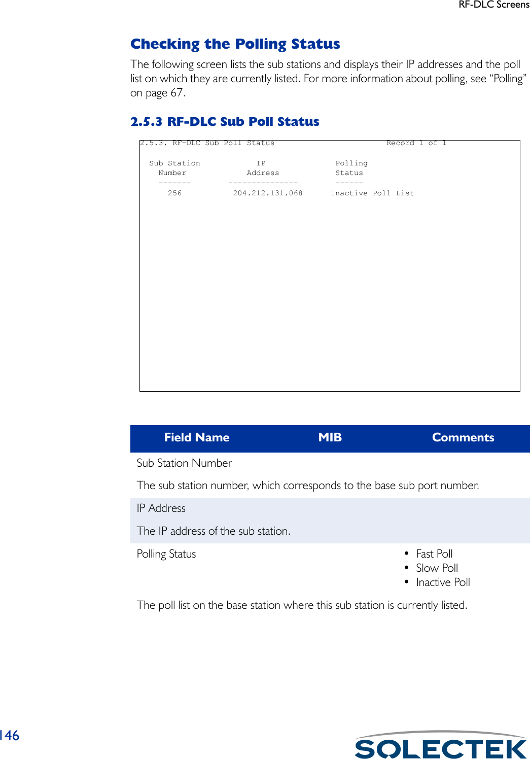
![IP Routing Screens162Destination Unreachable Errors[icmpInDestUnreachs] [icmpOutDestUnreachs]The number of ICMP Destination Unreachable messages received. This error is generated if the Default Time to Live count = 0 or less.Time Exceeded Errors [icmpInTimeExcds] [icmpOutTimeExcds]The number of ICMP Time Exceeded messages received.Address Mask Requests [icmpInAddrMasks] [icmpOutAddrMasks]The number of ICMP Address Mask Request messages received.Address Mask Replies [icmpInAddrMaskReps] [icmpOutAddrMaskReps]The number of ICMP Address Mask Reply messages received.Echo Requests [icmpInEchos] [icmpOutEchos]The number of ICMP Echo Request messages received. The Ping utility generates an Echo Request to test communications with another unit.Echo Replies [icmpInEchoReps] [icmpOutEchoReps]The number of ICMP Echo Request messages received. The Ping utility expects to receive this type of packet in response to an Echo Request.Source Quenches [icmpInSrcQuenchs] [icmpOutSrcQuenchs]The number of ICMP Source Quenches messages received.Router Redirects [icmpInRedirects] [icmpOutRedirects]The number of ICMP Redirect messages sent.Parameter Problems [icmpInParmProbs] [icmpOutParmProbs]The number of ICMP Parameter Problem messages received.Field Name MIB (Incoming) MIB (Outgoing)](https://usermanual.wiki/Solectek/24WAN5.Soletek-Skyway-Final-User-Guide/User-Guide-91948-Page-188.png)
![IP Routing Screens163Checking the Address Resolution Protocol TableThe Address Resolution Protocol (ARP) table contains the physical mapping of MAC to IP addresses. Use this table to add static IP ARP entries. Press .A to begin editing.2.4.1.5 ARP TableField Name MIB (Incoming) MIB (Outgoing)Port [ipNetToMediaIPIndex]The IP port at which the IP address can be reached.IP Address [ipNetToMediaNetAd-dress]The IP address.MAC Address [ipNetToMediaPhysAd-dress]The physical or MAC address.Ty p e [ipNetToMediaType] •STATIC•DYNAMIC•INVALIDWhether this entry is static or dynamic. Static values are user-entered, and dynamic entries are learned from the network. 2.4.1.5. ARP Table Record 0 of 0 Port IP Address MAC Address Type ---- --------------- ----------------- ------\ - return to menu . - commands TAB - next available field ENTER - edit](https://usermanual.wiki/Solectek/24WAN5.Soletek-Skyway-Final-User-Guide/User-Guide-91948-Page-189.png)