Solectek 24WAN5 Wireless LAN Bridge User Manual SkyWay Wireless Bridge Router User s Guide
Solectek Corporation Wireless LAN Bridge SkyWay Wireless Bridge Router User s Guide
Solectek >
Contents
- 1. Soletek Skyway Final User Guide
- 2. Revised System Specification Output levels
- 3. Solectek Revised User Guide Rev 101c
Soletek Skyway Final User Guide
i
www.solectek.com
SOLECTEK CORPORATION
6370 Nancy Ridge Dr.
Suite 109
San Diego, CA 92121
858-450-1220
fax 858-457-2681

ii
Ó Copyright Solectek Corporation 2000
All rights reserved. Reproduction, adaptation, or translation without prior written per-
mission is prohibited, except as allowed under the copyright laws.
Revision number 1.01
First edition, March 2000
Printed in USA
The information contained in this document is subject to change without notice.
Solectek Corporation makes no warranty of any kind with regard to this material,
including, but not limited to, the implied warranties or merchantability and fitness for a
particular purpose.
Solectek Corporation shall not be liable for errors contained herein or for incidental or
consequential damage in connection with the furnishing, performance, or use of this
material.

i
Regulatory Information
The SkyWay Series Wireless Bridge/Router operates in the 2.4 GHz band, complies
with the IEEE 802.1D MAC bridging standard and supports SNMP monitoring if IP
routing is enabled.
Federal Communications Commission (FCC) Radio
Frequency Interference Statement
This device complies with Part 15 of FCC Rules. Operation of this device is subject to
the following two conditions:
• It may not cause harmful interference.
• It must accept any interference that may cause undesired operation.
Information to the User
In order to comply with FCC RF exposure requirements, a minimum separation dis-
tance of 27 in. must be maintainted between the antenna and any persons. When
installing the antenna, ensure that this clearance is maintained while the product is in
operation.
This device must be installed and used in strict accordance with the manufacturer's
instructions. However, there is no guarantee that interference to radio communica-
tions will not occur in a particular commercial installation. In case the device does cause
harmful interference with an authorized radio service, the user/operator shall promptly
stop operating the device until harmful interference has been limited. Solectek Corpo-
ration is not responsible for any radio or television interference caused by unautho-
rized modification of this device or the substitution or attachment of connecting cables
and equipment other than specified by Solectek Corporation. The correction of inter-
ference caused by such unauthorized modification, substitution, or attachment will be
the responsibility of the user.

ii
Steps for
minimizing or
eliminating radio
and television
interference:
• Change the channel
• Reorient the radio or TV receiving antenna.
• Relocate the computer and SkyWay Series Wireless Bridge/Router unit with
respect to the receiver.
• Plug the computer and SkyWay Series Wireless Bridge/Router into a different
outlet so the computer and bridge/router are on different branch circuits.
If necessary, consult the dealer or an experienced radio/TV technician for additional
suggestions. You may find the booklet called "How to Identify and Resolve Radio-TV
Interference Problems" prepared by the Federal Communications Commission helpful.
The booklet is available from the U.S. Government Printing Office, Washington, D.C.,
20402, as stock number 004-000-00345-4.
This product was FCC certified under test conditions that included the use of shielded
I/O cables and connectors between system components. To be in compliance with
FCC regulations, the user must use shielded cables and connectors and install them
properly.
Radio Transmission Notice
This product is a low power (less than 1 Watt), direct-sequence, spread-spectrum
radio system pre-set to transmit and receive signals in the 2.4-2.4835 GHz frequency
band. This product has been certified by the U.S. Federal Communications Commis-
sion for use in the United States of America in that band. The manufacturer makes no
representation as to the availability of the above-mentioned frequency band for such
use in other countries.
Any prospective user of this product outside the United States of America should, prior
to such use, contact the government department or other agency responsible for
assigning radio frequencies in the country in which use is proposed to determine
whether such department or agency has any objection to operation of the product in
the 2.4-2.4835 GHz band, and whether there are any other local devices generating
signals in that band which might be expected to interfere with the operation of this
product.
The manufacturer shall not be responsible for any operation of this product which is in
violation of local law, creates interference harmful to other local devices, or results in a
malfunction of this product caused by outside interference.
End User License Agreement
Notice: Read below before installing and using this device. Installing and using this
device indicates your acceptance of these terms and conditions. If you do not accept
the terms, you must return the unused device and all related software immediately.
You may not use, copy, modify, or transfer the enclosed device, related documenta-
tion, or any software programs residing in or included with the device (collectively, the
"product"), except as expressly provided in this license.

Regulatory Information:
iii
License. The technology and intellectual property embodied in the Product (the
"Technology") are licensed, not sold, to you. You have a nonexclusive and nontransfer-
able right only to connect the Product to and to use the Technology with a single
license control utility. You may not modify or make inoperable authorization keys or
license control utilities. You may not transfer, sublicense or assign a license to the Prod-
uct or the Technology to another party except in accordance with Solectek's Product
License Transfer Policy in effect at the time of such license grant.
You understand that the Technology belongs to Solectek or its third party licensors (col-
lectively, "Solectek"), and they have the right to enforce this license. You agree to keep
confidential and use your best efforts to prevent and protect the contents of the Tech-
nology from unauthorized disclosure or use. Solectek reserves all rights not expressly
granted to you.
Limitations on use. You may not disclose or make available the Product or the
Technology to any other party or permit others to use it except your employees and
agents who use it on your behalf and who have agreed to these license terms. You
may not do any of the following with or to the Product or the Technology: (a) make
copies (except for backup or archival copies); (b) rent, lease or distribute copies; (c)
make any alteration, modification, translation or the like without the prior written con-
sent of Solectek; or (d) reverse engineer, reverse assemble, reverse compile or other-
wise engage in similar manipulation. Any full or partial copy of the Product must include
all copyright and other proprietary notices which appear on or in the Product.
You must maintain adequate records to be able to control use of the Product and the
Technology according to these license terms. These records must match the use of the
Product and the Technology to the license grants. Solectek may require you to make
these records available to Solectek or the third party developer or owner of the appli-
cable portion of the Product.
The term "authorization key" includes any unique series of data elements that is to be
installed and enabled in a license control utility to allow use of the Product. Authoriza-
tion keys may be installed and enabled for use in only one license control utility at any
one time. Authorization keys are non-transferable and confidential and must be
destroyed on termination of this license. Unless otherwise specified, you may print
electronic Product documentation as reasonably necessary to exercise your right to
use the Product.
Terms and Limitations. This license is effective until terminated. You may terminate
this license at any time by returning the Product to Solectek. This license automatically
terminates if you fail to comply with its terms and conditions. You agree that upon such
termination you will return the Product to Solectek, together with any other material
you have received from Solectek in connection with the Product.
U.S. governing law and export restrictions. This license will be governed by
the laws (other than choice of law principles) of the State of California, and in no event
will it be governed by the U.N. convention of the international sale of goods. You
acknowledge that the laws and regulations of the United States restrict the export and
re-export of the Product and any related technical data. You agree that you will not
export or re-export the Product or any related technical data in any form without first
obtaining the appropriate United States and foreign government approval.

iv
U.S. Government Restricted Rights Legend
The Product is provided with Restricted Rights. Use, duplication, reproduction or dis-
closure by the Government is subject to restrictions in subdivision (c)(1)(ii) of the Rights
in Technical Data and Computer Product clause at 252.227-7013 and in subpara-
graphs (a) through (d) of the Commercial Product-Restricted Rights Clause at 52.227-
19. Contractor/Manufacturer is Solectek, 6370 Nancy Ridge Drive, Suite 109, San
Diego, California.

Introduction
v
Introduction
The products and software programs described in this Users’ Guide are licensed prod-
ucts of SOLECTEK and are fully copyrighted. The information within this Operator’s
Guide is proprietary and also is copyrighted.
Information in this Operator’s Guide is subject to change without notice. While every
precaution has been taken in the preparation of this Guide, SOLECTEK assumes no
responsibility for inaccuracies. The Operator’s Guide may not be reproduced or trans-
mitted in any form or by any means, electronic or mechanical, including photocopying,
recording, or information retrieval systems, for any purpose other than the purchaser’s
personal use, without the expressed, written permission of SOLECTEK.
It is the policy of SOLECTEK to improve its products as new technology, components,
software, and firmware become available. SOLECTEK Corporation, therefore,
reserves the right to change specifications without prior notice. Furthermore, all fea-
tures, functions, and operations described herein may not be marketed by SOLECTEK
in all parts of the world.
SOLECTEK is the name and trademark of SOLECTEK Corporation. SkyWay is a
trademark of SOLECTEK Corporation.
SOLECTEK does not warrant that the hardware and software of its product will func-
tion as intended in every environment and application, and makes no warranty and
representation, either implied or expressed, with respect to the quality, performance,
merchantability, or fitness for every purpose.
Other trademarks:
IBM and AT are registered trademarks of International Business Machines Corporation.
Microsoft and MS-DOS are registered trademarks of Microsoft Corporation. Novell
and NetWare are registered trademarks of Novell, Inc. Other trademarks are the
property of their respective holders.
Copyright January 2000 SOLECTEK Corporation, San Diego, California, U.S.A.
All Rights Reserved. Printed in the U.S.A.
Tel: (858)450-1220
Web Site: www.solectek.com
Part Number:

vi
Contact Information
If the information in this Users’ Guide does not answer your questions, please contact
SOLECTEK Corporation’s Technical Support Department. Our friendly and knowl-
edgeable Technical Support staff is available to answer your questions Monday through
friday, 8:00 a.m. to 5:00 p.m., Pacific Time. If you prefer, you can submit questions to
our 24-hour fax number or by e-mail.
Voice support: (858)450-1220
24-hour fax number: (858)457-2681
E-mail address: support@solectek.com
To handle your call as quickly and effectively as possible, please have the following
information ready before you call.
• The model you are using (SkyWay Bridge/Router).
• The type of Ethernet connection your SkyWay Bridge/Router has (10BaseT or
100BaseF).
• The network to which you are connected (for example, Novell NetWare,
version xx).
• The application you were using when you encountered the problem (for
example, Word for Windows, version 7.0).
• Any symptoms or error codes that accompanied the problem (for example,
activities were suspended or a “123ABC” error code appeared.).
• The results of the most recent bench test (see page xxx).

Warranty
vii
Warranty
One Year Limited Warranty
Subject to the conditions and procedures set forth below during the warranty period,
Solectek will repair or replace, at Solectek’s option, such Solectek products or parts
thereof which, on inspection by Solectek, are found to be covered by the limited war-
ranties set forth below. The warranty period for new hardware products, which are
listed on Solectek’s MSRP Price List at time of purchase, is twelve months from the
date of shipment from Solectek. The warranty period for spare parts and R- part num-
bers is ninety days from the date of shipment from Solectek. If you think there is a
problem or defect with your Solectek product:
• Contact Solectek’s Technical Support Department between 8:00 a.m. and
5:00 p.m., Pacific Time at (858) 450-1220, or via fax at (858) 457-2681, or via
e-mail at support@solectek.com. The Solectek Technical Support Representa-
tive will discuss your problem to confirm the defect. After business hours,
please leave a voicemail or send an e-mail or fax. A Technical Support Repre-
sentative will respond to you the next business day.
• If warranty or return service is needed, you will receive a Return Material
Authorization (RMA) number. At no time should Solectek products be sent
back without a valid RMA number. Solectek accepts no responsibility for unau-
thorized returns.
You agree to pay for shipping to Solectek. If the product is under warranty, Solectek
You agree to pay for shipping to Solectek. If the product is under warranty, Solectek You agree to pay for shipping to Solectek. If the product is under warranty, Solectek
You agree to pay for shipping to Solectek. If the product is under warranty, Solectek
will pay for shipping of the repaired or replacement product to you via ground trans-
will pay for shipping of the repaired or replacement product to you via ground trans-will pay for shipping of the repaired or replacement product to you via ground trans-
will pay for shipping of the repaired or replacement product to you via ground trans-
portation to your location in the United States. For installations outside the continental
portation to your location in the United States. For installations outside the continental portation to your location in the United States. For installations outside the continental
portation to your location in the United States. For installations outside the continental
U.S., Solectek will pay for shipping via ground transportation to the freight forwarder of
U.S., Solectek will pay for shipping via ground transportation to the freight forwarder of U.S., Solectek will pay for shipping via ground transportation to the freight forwarder of
U.S., Solectek will pay for shipping via ground transportation to the freight forwarder of
your choice located in the continental United States. Any other freight arrangements
your choice located in the continental United States. Any other freight arrangements your choice located in the continental United States. Any other freight arrangements
your choice located in the continental United States. Any other freight arrangements
will be at customer expense.
will be at customer expense.will be at customer expense.
will be at customer expense.
Solectek shall not be liable for any damage caused to the product in transit. You
Solectek shall not be liable for any damage caused to the product in transit. You Solectek shall not be liable for any damage caused to the product in transit. You
Solectek shall not be liable for any damage caused to the product in transit. You
acknowledge and agree you will bear all risk of loss or damage to the product while
acknowledge and agree you will bear all risk of loss or damage to the product while acknowledge and agree you will bear all risk of loss or damage to the product while
acknowledge and agree you will bear all risk of loss or damage to the product while
in transit.
in transit.in transit.
in transit.
Send return shipments to:
Solectek Corporation
6370 Nancy Ridge Drive, Suite 109
San Diego, CA 92121-3212
ATTN: RMA # ________
• Pack products securely, to prevent damage in transit. Be sure the RMA num-
ber is clearly visible on the outside of the return shipping carton.
• Returned Solectek products must include all other components from the origi-
nal package, including the hardware, cables, connectors, software diskettes,
and user manual(s) unless otherwise stipulated by Solectek.
• Enclose a copy of the original purchaser’s proof of purchase, if needed to sup-
port warranty claim. (See details in LIMITATIONS section below.)

viii
After inspecting the failed unit, Solectek will repair or replace materially defective parts
or components. All products that are replaced become the property of Solectek. If
upon inspection by Solectek, a unit returned under warranty is deemed to be damaged
or out of warranty for any reason, (see LIMITATIONS section below), Solectek will
contact the customer with a price for the repair or replacement unit. Upon receipt of
payment (wire transfer, certified check, credit card, etc.) for the replacement unit plus
outbound shipping fees, Solectek will send a repaired or replacement unit to the cus-
tomer. Customers who do not accept the repair offer may receive their failed equip-
ment back by prepaying an inspection fee of $300 and the return freight cost.
If upon inspection by Solectek, a unit returned under warranty is found to be defect
free, Solectek reserves the right to charge the customer a $500 test fee.
SOLECTEK’S SOLE AND EXCLUSIVE OBLIGATION, AND YOUR SOLE AND
EXCLUSIVE REMEDY, UNDER THIS LIMITED WARRANTY SHALL BE THE REPAIR
OR REPLACEMENT OF THE APPLICABLE SOLECTEK PRODUCT IN ACCOR-
DANCE WITH THE TERMS SET FORTH HEREIN.
LIMITATIONS
As the original purchaser, you receive these warranties from Solectek Corporation,
subject to the terms and limitations set forth below.
Solectek warrants that your Solectek products will be free from defects in material and
workmanship and will perform in substantial compliance with the operator’s guide(s)
accompanying Solectek products. Warranty is given for twelve (12) months from the
date of product shipment from Solectek for new hardware products and ninety (90)
days for spare parts and R- part numbers. Solectek will honor this warranty upon
receiving proof of purchase. “Proof of purchase” is a copy of the original sales transac-
tion, showing complete name and address of seller, complete name and address of
purchaser, date of purchase, model number, and serial number.
Solectek does not cover or accept liability for any injury, damage or failure caused by
misuse, misapplication, abuse, acts of nature, accidents (e.g., dropping the Solectek
products or software diskettes), electrical mishaps, causes beyond our control, or
claims by other than the original purchaser.
Solectek will not honor, and will consider this limited warranty voided, if, in Solectek’s
reasonable judgment, there has been any (1) tampering with the Solectek product’s
external label or serial number, (2) attempt to open the Solectek product’s case with-
out prior written consent from Solectek, (3) attempted or actual repair by anyone
other than an authorized Solectek technician, (4) installation or use with any power
supply component(s) other than the original Solectek power supply components pro-
vided in the product package, (5) for installations within the U.S., installation or use
with any cables or antenna(s) other than original Solectek products, (6) installation or
use in environmental conditions that are outside Solectek’s published environmental
specifications (including but not limited to temperature range, humidity, cable lengths,
proximity to other devices, etc.).
This warranty is available only to the initial end user purchaser of the product and is not
transferable. This warranty is applicable only to products purchased using Solectek’s

Warranty
ix
MSRP Price List. Warranty is void if a Solectek product is installed at a destination other
than the stated destination at time of purchase.
DISCLAIMER OF WARRANTIES
EXCEPT AS EXPRESSLY SET FORTH HEREIN, SOLECTEK HEREBY EXPRESSLY
DISCLAIMS ANY AND ALL WARRANTIES, EXPRESS OR IMPLIED, INCLUDING
WITHOUT LIMITATION THE IMPLIED WARRANTIES OF MERCHANTABILITY
OR FITNESS FOR A PARTICULAR USE.
WAIVER OF CONSEQUENTIAL DAMAGES
SOLECTEK HEREBY DISCLAIMS ANY AND ALL SPECIAL, INDIRECT, OR CONSE-
QUENTIAL DAMAGES (INCLUDING WITHOUT LIMITATION, LOST PROFITS,
LOSS OF OR DAMAGE TO ANY OTHER COMPUTER EQUIPMENT OR RELATED
DATA) WHICH MAY RESULT FROM BREACH OF ANY WARRANTY, OR ARISING
OUT OF THE USE OR INABILITY TO USE ANY SOLECTEK PRODUCT, EVEN IF
SOLECTEK HAS BEEN ADVISED OF THE POSSIBILITY OF SUCH DAMAGES.

x

xi
Table of Contents
Table of ContentsTable of Contents
Table of Contents
Regulatory Information: ...................................... i
Federal Communications Commission (FCC) Radio Frequency
Interference Statement .............................................................i
Information to the User................................................................i
Radio Transmission Notice ..........................................................ii
End User License Agreement ......................................................ii
U.S. Government Restricted Rights Legend ..............................iv
Introduction .........................................................v
Contact Information ...........................................vi
Warranty ............................................................vii
One Year Limited Warranty ...................................................... vii
LIMITATIONS ........................................................................... viii
DISCLAIMER OF WARRANTIES................................................... ix
WAIVER OF CONSEQUENTIAL DAMAGES............................... ix

xii
Chapter 1:
Introducing Skyway.............................1
Intended Audience .............................................. 2
Using this Guide .................................................. 3
Conventions, warnings ........................................ 5
Menu and Command Names .......................................................5
Typed Text ...................................................................................5
Notes ............................................................................................5
Warnings.......................................................................................5
Hyperjumps ..................................................................................5
How to Proceed .................................................. 6
Chapter 2:
Getting to Know the SkyWay Bridge/
Router .................................................7
General Description ............................................ 8
Product Features ................................................ 9
Contents of the SkyWay Package ..................... 10
Component Identification ................................. 11
Specifications..................................................... 12
Understanding the Menu Structure.................. 13

xiii
Navigating Through Menus and Screens ..................................13
Dot Commands ..........................................................................14
How Screens Display Information .............................................15
Editing Fields ..............................................................................15
Field Types.................................................................................... 15
Saving Configuration Changes...................................................16
Understanding the Configuration Database .............................16
Changes that Require Cycling or Resetting ..............................16
Resetting the Unit ......................................................................... 16
Bios Application ................................................ 18
Bios Main Menu..........................................................................18
Bios Main Menu ............................................................................ 18
Bios Configuration Menu .............................................................. 19
Bios System Configuration ............................................................ 20
Configuration Database Service.................................................... 21
Accessing the SkyWay Bridge/Router ............... 22
Modem Settings for Dial-up Connection ...................................... 22
Configuring the Serial Port and Serial Transceiver ..................23
1.2.1.1 Serial Port Configuration .................................................. 24
1.2.1.2 Serial Transceiver Configuration....................................... 25
Chapter 3:
Preparing for Installation..................27
Before Installing ................................................ 28
Safety Considerations ....................................... 29
General Safety Guidelines..........................................................29
Electrical Safety Guidelines........................................................29
Pre-installation Procedures.............................. 30

xiv
Site Considerations ....................................................................30
Step One: Assess Your Network Requirements .......................... 30
Step Two: Map Wireless Network Pre-Design ............................ 30
Step Three: Perform a Site Survey ............................................... 31
Step Four: Finalize the Design ...................................................... 31
Bench Test......................................................... 32
Minimum Configuration Settings and Factory Defaults for Bench
Test ..........................................................................................32
Performing the Bench Test........................................................33
Chapter 4:
Installing Skyway ...............................41
Mounting the SkyWay Unit ............................... 42
Mounting to a Mast ....................................................................42
Mounting to a Wall.....................................................................44
Setting Up the Antenna .................................... 45
Selecting the Antenna ...............................................................45
Before You Mount the Antenna ................................................45
Mounting the Antenna...............................................................46
Grounding Skyway and the Antenna ................ 47
Connecting Cabling............................................ 48
Routing Connected Cables ........................................................48
Connecting an Antenna .............................................................49
Connecting to Power .................................................................50
Connecting to the Administration Console ..............................51
Connecting to Your LAN ...........................................................53

xv
Antenna Alignment and RF Link Verification ... 55
Chapter 5:
Configuring and Managing SkyWay....57
Configuring SkyWay........................................... 58
Configuration Features Available ..............................................58
Setting System Configuration Parameters ....... 59
Setting Network Management Security Parameters...............59
1.1.1 Network Management Security Configuration.................... 59
Setting Network Management System Parameters ................61
1.1.2 Network Management System Configuration ..................... 61
Adding Users and Setting Access Levels...................................62
1.1.3.1 Add a User ........................................................................ 62
Displaying a List of Users ...........................................................63
1.1.3.2 Users................................................................................. 63
Setting the System Date and Time ...........................................64
1.1.4 General Parameters Configuration ...................................... 64
Understanding RF-DLC...................................... 65
The RF-DLC Protocol.................................................................65
Automatic Discovery Protocol...................................................65
Enabling ADP ................................................................................ 65
Disabling ADP ............................................................................... 66
ADP Discovery Process ................................................................ 66
RF-DLC Frame Types.................................................................67
RF-DLC Commands and Responses............................................. 67
Polling .........................................................................................67
Error Detection and Recovery...................................................... 68

xvi
Configuring the Ports........................................ 69
Before you Begin ........................................................................69
Obtaining IP Addresses..............................................................69
Setting up IP Addresses.............................................................69
Configuring the SkyWay as a Base Station ...............................69
1.2.3.3 RF Transceiver Configuration ........................................... 72
RF Diagnostics Port....................................................................... 73
1.2.3.2 RF Diagnostic Port Configuration ..................................... 73
1.2.3.1.1 RF Base Port Configuration ........................................... 74
Configuring the SkyWay as a Sub Station.................................77
1.2.3.1.2 RF Sub Port Configuration ............................................. 78
Configuring the Base Sub Ports .................................................... 80
Validating Accept Status of a Sub Station ................................81
1.2.3.1.4 ADP Substation Configuration ....................................... 81
Configuring the Ethernet Port...................................................83
1.2.2.1 Ethernet Port Configuration ............................................. 83
Configuring the Ethernet Transceiver.......................................85
1.2.2.2 Ethernet Transceiver Configuration ................................. 85
Bridging ............................................................. 88
Enabling and Disabling Bridging ................................................88
Port States..................................................................................... 88
Spanning Tree ............................................................................89
1.3.1 Bridge Configuration............................................................ 90
1.3.2 Bridge Port Configuration.................................................... 92
IP Routing.......................................................... 93
Configuring IP.............................................................................93
1.4.1 IP Protocol Configuration .................................................... 93
Configuring the IP Ports ............................................................95
1.4.2 IP Port Configuration ........................................................... 95
Setting up Static Routing...........................................................97
1.4.3 IP Static Routes Configuration ............................................. 97

xvii
BOOTP .......................................................................................98
Obtaining a Configuration Summary ........................................99
1.5 Configuration Summary ........................................................ 100
Internet Control Message Protocol ................ 102
SNMP ............................................................... 103
SNMP Features Available ........................................................103
Diagnostics ...................................................... 104
BIOS Diagnostics......................................................................104
RunTime Diagnostics ...............................................................104
4.1 RF Base Radio Test ............................................................... 105
4.2 RF Sub Radio Test................................................................. 107
Ping Utility................................................................................108
3.2 Ping Utility............................................................................. 109
File Directory............................................................................111
3.1.4 File Directory..................................................................... 111
File Transfer Utilities ...................................... 112
Xmodem...................................................................................112
YModem ...................................................................................113
3.1.2 YModem ............................................................................ 114
Uploading a New Software Version ........................................115
Trivial File Transfer Protocol ...................................................116
TFTP Clients and Server............................................................. 117
Sending and Receiving Files......................................................... 117
File Definitions ............................................................................ 118
TFTP Status ................................................................................ 119
Configuring the TFTP Server on SkyWay ................................... 119
3.1.1.2 TFTP File Transfer .......................................................121

xviii
Security ........................................................... 123
Multi-level Password Security .................................................123
SNMP Security .........................................................................123
Chapter 6:
Monitoring SkyWay..........................125
Monitoring Features Available........................ 126
System Status and Control Screens ................ 127
Taking a System Snap Shot .....................................................127
2.1.1 General Status and Control ............................................... 127
Checking SNMP Status and Trap History ..............................128
2.1.2.1 SNMP Status ................................................................... 128
2.1.2.2 SNMP Trap History ........................................................ 129
Checking the Error Log............................................................130
Port Status and Control Screens .................... 132
Checking the Serial Port Status ..............................................132
2.2.2 Serial Port Status................................................................ 132
Checking the Ethernet Port Status.........................................134
2.2.3.1 Ethernet Port Status ....................................................... 134
2.2.3.2 Ethernet Transceiver Status............................................ 136
Checking the RF Port...............................................................137
2.2.4 RF Port Status .................................................................... 137
RF-DLC Screens ............................................... 140
Checking RF-DLC Base Port Status ........................................140
2.5.1 RF-DLC Base Port Status................................................... 140
Checking the Sub Port Status .................................................143
2.5.2 RF-DLC Sub Port Status .................................................... 143
Checking the Polling Status.....................................................146

xix
2.5.3 RF-DLC Sub Poll Status ..................................................... 146
Checking the RF Signal Status.................................................147
2.5.4 RF Signal Status .................................................................. 147
Bridging Screens.............................................. 149
Checking Bridge and Spanning Tree Status ...........................149
2.3.1 Bridge and Spanning Tree Status ....................................... 149
Checking Bridge Port Status ...................................................152
2.3.2 Bridge Port Status .............................................................. 152
Checking Spanning Tree Port Status......................................154
2.3.3 Spanning Tree Port Status.................................................. 154
Transparent Bridging Table.....................................................156
2.3.4 Transparent Bridging Table ............................................... 156
IP Routing Screens .......................................... 157
Checking IP Routing Status .....................................................157
2.4.1.1 IP Protocol Status ........................................................... 157
2.4.1.2 IP Address Table ............................................................. 160
Checking ICMP Activity ...........................................................161
2.4.1.4 ICMP Status .................................................................... 161
Checking the Address Resolution Protocol Table ..................163
2.4.1.5 ARP Table ....................................................................... 163
Base Station States ......................................... 164
Sub Station States ...................................................................166
Status Summary .............................................. 168
Checking the Status Summary ................................................168
2.6 Status Summary .................................................................... 168

xx
Chapter 7:
Troubleshooting Skyway .................171
Symptom/Action Flowchart ............................ 172
Before You Call Solectek Tech Support.......... 173
Detailed description of the problem........................................... 173
2.1.1 General Status and Control Information............................ 173
Network Configuration .............................................................. 174
RF Network Configuration ......................................................... 174
Logical Network Map ................................................................. 174
Bench Test Results...................................................................... 174
Appendix A:
Run-time Menu Tree .......................175
Appendix B:
BIOS Menu Tree Summary Table.....179
Appendix C:
Interface Specifications and
Pinouts.............................................181
DC Power Cable (Female DC Jack).................. 182
Console Cable (Serial RS-422: DB9)................ 183
10 Base-T/100 Base-TX (Ethernet Cable:
RJ-45) ............................................................ 184

xxi
Appendix D:
Detailed Product Specifications ......185
Appendix E:
Supported Protocols .......................187
Bridged Protocols.....................................................................187
Routed Protocols......................................................................187
Management Protocols ............................................................187
Appendix F:
Error Codes .....................................189
Appendix G:
SNMP Trap Messages.......................191
Appendix H:
Installation Recording Form............193
Appendix I:
Sources of SNMP Management
Software ..........................................195

xxii
Appendix J:
Glossary and Basic Concepts ...........197
Basic Concepts ................................................ 198
Units of Measure ............................................. 201
Connection Types............................................ 203
Antennas ......................................................... 204
Protocols ......................................................... 208
Equipment ....................................................... 209
Site Survey ...................................................... 210
Appendix K:
Skyway Antennas ............................213
7002301: 6 dBi Omni Directional Antenna..... 214
Specifications............................................................................214
Wall Mount ...............................................................................215
Mast Mount ..............................................................................215
7002401: 11 dBi Omni Directional Antenna... 216
Specifications............................................................................216
Wall Mount ...............................................................................217
Mast Mount ..............................................................................217
7002501: 16 dBi Outdoor Flat Panel Directional

xxiii
Antenna......................................................... 218
Specifications............................................................................218
Wall Mount ...............................................................................219
Mast Mount ..............................................................................219
7002601: 17 dBi Outdoor Flat Panel Directional
Antenna......................................................... 220
Specifications............................................................................220
Wall Mount ...............................................................................221
Mast Mount ..............................................................................221
7002701: 22 dBi Outdoor High gain Flat Panel Di-
rectional Antenna ......................................... 222
Specifications............................................................................222
Wall Mount ...............................................................................223
Mast Mount ..............................................................................223
7002801: 8 dBi Indoor/Outdoor Patch Antenna ..
224
Specifications............................................................................224
Wall Mount ...............................................................................225
Mast Mount ..............................................................................225
7002901: 12 dBi 110 ° Outdoor Sectorial Antenna
226
Specifications............................................................................226
Wall Mount ...............................................................................227
Mast Mount ..............................................................................227


1
Chapter 1:
Chapter 1: Chapter 1:
Chapter 1:
Introducing Skyway
Introducing SkywayIntroducing Skyway
Introducing Skyway
This User's Guide helps you install, configure, and manage the SkyWay Wireless
Bridge/Router. This Guide also covers selected SkyWay Bridge/Router maintenance
and troubleshooting procedures.
This chapter includes the following information:
Intended Audience.............................................................. 2
Using this Guide ................................................................. 3
Conventions, warnings ....................................................... 5
How to Proceed................................................................. 6

2
Intended Audience
This Users’ Guide contains everything you need to know to prepare for installation,
install, and configure a SkyWay Wireless Bridge/Router. It assumes the following:
• You are functioning in an Information Services or Building Facilities capacity
• You have more than one year’s experience with networking, either wireless or
traditional
• You are familiar with basic networking concepts such as bridging, IP routing,
WAN protocols, etc.
• You are familiar with your LAN or WAN’s topology, configuration, and design
• If you will be using Simple Network Management Protocol to manage SkyWay,
you are familiar with the protocol’s terms and usage
• You are familiar with basic RF/wireless network design, even if you are not
familiar with the particulars of any specific system
Note If you do not have the knowledge listed above, we recommend that you hire a con-
sultant to assist you with installing and configuring your SkyWay and network.

Using this Guide
3
Using this Guide
This guide contains the following chapters and appendixes:
•Chapter 1 (this chapter)
• Chapter 2: Getting to Know the SkyWay Bridge/Router
This chapter provides an overview of the features and physical elements of the
SkyWay Wireless Bridge/Router, including how to use the Administrative Con-
sole.
• Chapter 3: Preparing for Installation
This chapter explains how to plan a successful SkyWay installation, including a
brief discussion of site design and detailed bench testing instructions.
• Chapter 4: Installing Skyway
This chapter discusses how to mount and connect SkyWay.
• Chapter 5: Configuring and Managing SkyWay
This chapter discusses how to configure SkyWay as a bridge, a router, or both,
including instructions for setting up base and substations.
• Chapter 6: Monitoring SkyWay
This chapter describes the SkyWay utilities you can use to monitor transmis-
sion and routing performance.
• Chapter 7: Troubleshooting Skyway
This chapter presents a method for diagnosing problems you may have with
the unit. It also includes instructions for contacting Solectek Technical Support.
• Appendix A: Run-time Menu Tree
This appendix provides a summary of the SkyWay menu structure, including
cross-reference to more detailed information.
• Appendix B: BIOS Menu Tree Summary Table
This appendix provides a list of the BIOS menu tree, including cross-reference
to more detailed information.
• Appendix C: Interface Specifications and Pinouts
This appendix explains the pins and wire color for each of the SkyWay connec-
tors, in case you ever need to repair a cable.
• Appendix D: Detailed Product Specifications
This appendix lists the specifications for SkyWay components and connectors.
• Appendix E: Supported Protocols
This appendix details the routing and bridging protocols SkyWay supports.
• Appendix F: Error Codes
This appendix describes the error codes the SkyWay administration console
may provide.

4
• Appendix G: SNMP Trap Messages
This appendix lists the standard and enterprise SNMP traps.
• Appendix H: Installation Recording Form
This appendix provides the forms you should use to record installation param-
eters.
• Appendix I: Sources of SNMP Management Software
This appendix explains where to obtain SNMP management software.
• Appendix J: Glossary and Basic Concepts
This appendix lists and defines important terms used in this manual.
• Appendix K: Skyway Antennas
This appendix lists antenna specifications.
• Index

Conventions, warnings
5
Conventions, warnings
The following conventions are used in this Operator's Guide.
Menu and Command Names
Menu and command names appear in a bold typeface
bold typefacebold typeface
bold typeface.
Typed Text
Screen commands and text you are to type appear in a Courier typeface.
Notes
Notes are information requiring your attention.
Warnings
Warnings are statements that, if you ignore them, can damage the SkyWay
Bridge/Router or cause injury to yourself or others.
Hyperjumps
This guide contains hyperjumps to make it easy to navigate the PDF version of this
book. Click on cross-references, TOC listings, or index entries to go to the appropri-
ate page. The chapter number and names under “Using this Guide” on page 3, are
examples of hyperjumps. For example, if you click “Chapter 2: Getting to Know the
SkyWay Bridge/Router” you go to the first page in Chapter 2.

6
How to Proceed
Review this manual before proceeding further. The chapters present the information
you need to begin in the order you will need it.

7
Chapter 2:
Chapter 2: Chapter 2:
Chapter 2:
Getting to Know the SkyWay
Getting to Know the SkyWay Getting to Know the SkyWay
Getting to Know the SkyWay
Bridge/Router
Bridge/RouterBridge/Router
Bridge/Router
Before setting up, configuring, and testing your new bridge/router, take a minute to
review its components and features.
This chapter includes the following information:
General Description ........................................................... 8
Product Features................................................................. 9
Contents of the SkyWay Package....................................... 10
Component Identification ................................................. 11
Specifications .................................................................... 12
Understanding the Menu Structure ................................... 13
Bios Application ................................................................ 18
Accessing the SkyWay Bridge/Router................................. 22

8
General Description
SkyWay -- The Long Distance Connection. The SkyWay series of products
allows you to set up high-speed, wide area networks over long distances. SkyWay
gives you the power to establish LAN-to-LAN connections over distances of up to 30
miles (48 km) - with superior performance. Each SkyWay unit is a compact, single,
integrated outdoor unit designed to withstand harsh environments—there is no need
for an indoor unit. SkyWay can be mounted on a mast or tower up to 4,000 feet
(1200m)away from the LAN. This reach enables you to deploy far less equipment to
cover your service area.
Point-to-Point or Multi-Point Application. SkyWay products can be used any-
where high speed data transfer or Internet access is required including corporate
offices, educational campuses, healthcare facilities, manufacturing, or retail. Configura-
tions can be set for Point-to-Point or Multi-Point applications.
Each SkyWay can function as a base station (central site), a substation (remote site), or
either end of a point-to-point link. Solectek’s broad selection of certified antennas
ensures that you get exactly the radio coverage you need.
Remote Operations. With SkyWay Series products, all management functions,
monitoring, and software updates can be performed remotely from any desired loca-
tion.
Support. Solectek offers a world-wide network of factory trained resellers as well as
on-site and on-line technical assistance programs.

Product Features
9
Product Features
The SkyWay Bridge/Router include the following key features:
• Up to 11 Mbps wireless data rate (up to 64 sub-stations)
• Links of distances up to 30 miles (48 km)
• Single, ruggedized, mast-mounted unit (UL Outdoor rated)
• Fiber-optic and copper Ethernet options
• Bridging and static IP routing
• SNMP compliant
• Optional fiber link for extra long distances or EMI protection
• Remote software updates via TFTP, Xmodem, or Ymodem
• FCC, Industrie Canada, ETSI, and UL certified
• Milspec connectors/industrial components for ultra-reliable service
• Secure Authentication Features
• Spanning Tree Configurations
• Supports DC voltage

10
Contents of the SkyWay Package
Before unpacking the SkyWay, examine the shipping containers and contents for dam-
age. If you spot container damage, notify your shipper immediately.
Report any missing parts and any damage not related to shipping to your place of pur-
chase immediately.
The SkyWay shipment includes three packages:
• The SkyWay Bridge/Router (including pole or wall mounting kit)
• The SkyWay cable kit:
a. A DC power cable and AC/DC converter
b. A console cable (RS-422 cable and RS-422 to RS-232 converter)
c. An Ethernet cable (either 10 Base-T/100 Base-TX or 100 Base-FX,
depending on the configuration ordered)
d. A LMR-400 RF cable
• The SkyWay antenna kit (omni or directional, as ordered by customer) and a
test antenna
This User’s Guide will also be enclosed.
Note: Keep the packing materials for future use. All components returned under warranty
must be packed in their original packing materials.
Component Identification
11
Component Identification
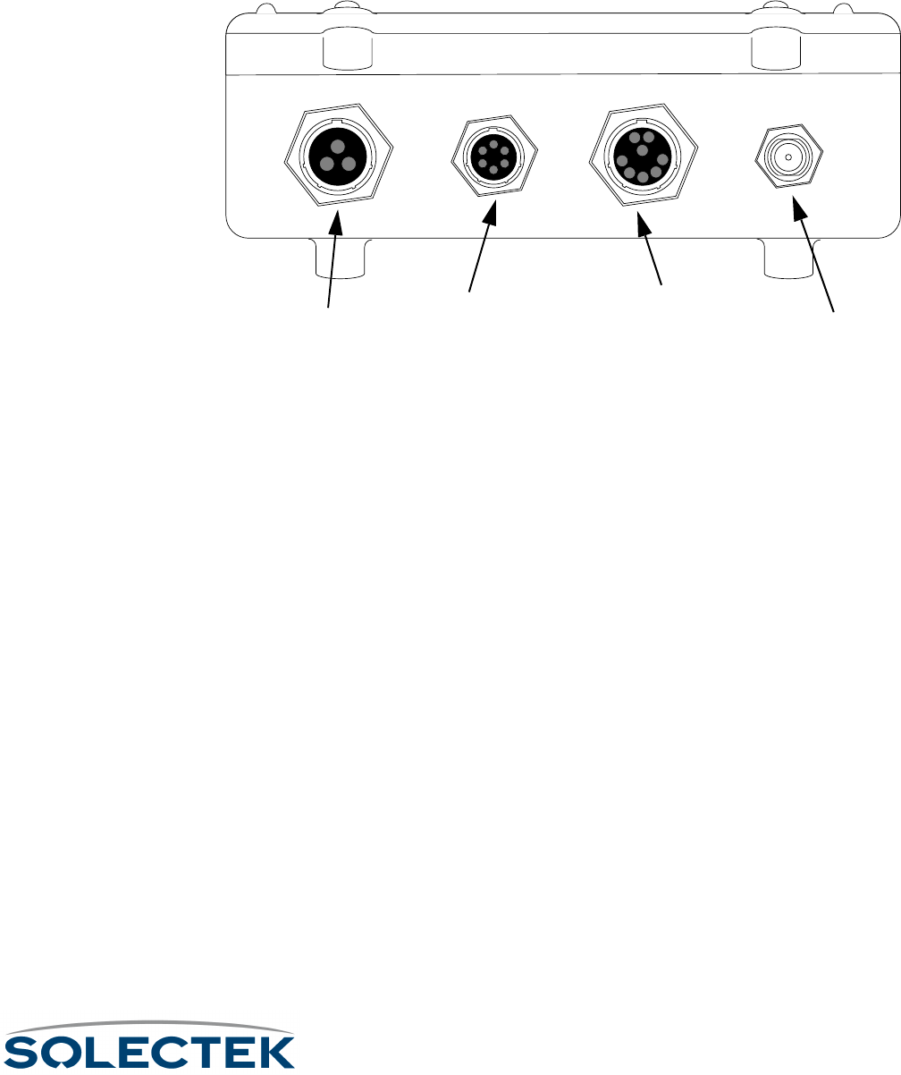
The Skyway wireless bridge/router includes the following components:
• a ruggedized, weatherproof casing
• four connectors:
Bottom View of the SkyWay Bridge/Router
Bottom View of the SkyWay Bridge/RouterBottom View of the SkyWay Bridge/Router
Bottom View of the SkyWay Bridge/Router
Power. The power receptacle (3 pin) accommodates the DC power cable supplied
with the SkyWay; it accepts 48 V DC. To apply or remove power, connect or discon-
nect the power cord to or from the AC/DC power converter.
Administration Console. The EIA/TIA-422 console connector (6 pin) accommo-
dates the console cable supplied with the SkyWay. The opposite end of the cable has a
DB-9 RS-422 connector that connects to a supplied RS-422 to RS 232 converter that
you connect to the RS-232 port of your PC or terminal. You can also connect the con-
verter to your modem. For a diagram, see “Accessing the SkyWay Bridge/Router” on
page 22.
Ethernet Port. The Data/Ethernet connector accommodates one of the following
two cables depending on the SkyWay model you ordered:
• 10/100 Base-TX (twisted pair) (8 pin)
• 100 Base-FX (fiberoptic) (2 pin)
The opposite end of either cable connects to your LAN or WAN server’s Ethernet
port.
RF. The RF connector (“N” type female) accommodates an LMR-400 RF coaxial cable
that connects to an RF antenna. For more information about antennas, see “Appendix
K: Skyway Antennas” on page 213.
For pinout information, see “Appendix C: Interface Specifications and Pinouts” on
page 181.
Power
PowerPower
Power Administration
AdministrationAdministration
Administration
Console
ConsoleConsole
Console
Ethernet
EthernetEthernet
Ethernet
10 /100 Base-TX (shown)
10 /100 Base-TX (shown)10 /100 Base-TX (shown)
10 /100 Base-TX (shown)
or 100 Base-FX
or 100 Base-FXor 100 Base-FX
or 100 Base-FX RF Antenna
RF Antenna RF Antenna
RF Antenna


Understanding the Menu Structure
13
Understanding the Menu Structure
The SkyWay screens are organized by function, and are hierarchically numbered. The
Run Time Main Menu is shown below:
The Configuration menu, option 1, shows you a list of 5 options. For example, 1.1
System Configuration, 1.2 Port Configuration, etc. For a complete list of the screens in
the menu tree, refer to “Appendix A: Run-time Menu Tree” on page 175, and “BIOS
M e n u Tr e e S u m m a r y Ta b l e ” o n p ag e 1 7 9 .
For information on the Bios Application, see
Navigating Through Menus and Screens
Use the keys in the following table to navigate through the menus:
To …
To …To …
To … Press This Key…
Press This Key…Press This Key…
Press This Key…
Move down or up through menu
options
Down- or Up-Arrow
Move through list of field entries Right- or Left-Arrow or space bar
Select an item or edit a field Enter
Go up one menu level \ (Blackslash)
Move between fields Tab, Up- or Down-Arrow
Enter a command .(dot) followed by the command. (see “Dot
Commands” on page 14)
Go directly to a particular screen if
you know the screen number
From the Main Menu, enter the screen num-
ber. From other screens where commands are
available, press . (dot), then type the number
of the screen. The screen title appears above
the number. If this is the screen you want,
press Enter.

14
Dot Commands
You can access commands from all non-menu screens. When they are available,
. - commands appears at the bottom of the screen. Press . to display the com-
mand line which lists the available commands for that screen, that is, not all commands
are available on every screen. The following table describes the commands:
.H Go to the HELP screen, which lists arrow keys
and . commands.
.M Monitor Mode on or off. Monitor mode con-
tinuously refreshes the data displayed, allowing
you to see the system operating in real time.
.R Update screen data (refresh)
.W Save screen data to the database (write). This
is usually required after you make a configura-
tion change before the change takes affect.
.A Add a new record to a table
.N Display the next record in a table.
.P Display the previous record in a table.
.C Cancel any changes made to this screen
before
beforebefore
before you press .W
.G Go to the specific table record by key value
(for example, port number).
.Z Clears the statistics on the current status
screen (zero)
.F Flushes tables. Available for these screens:
• 2.1.3 Error Log Screen
• 2.3.4 Transparent Bridging Table
• 2.4.1.5 ARP Table
This is functionally the same as accessing the
3.3 Flush utility, which allows you to flush one
or more of the above tables at a time.
.(dot) Use to go to a particular screen number. Type
. (dot), then type the screen number you
want to go to (for example, 224) and press
Enter. You cannot use this method at a menu
screen.

Understanding the Menu Structure
15
How Screens Display Information
Configuration and status records are displayed in the following formats:
• As a static variable
• As a table with many rows or records
• As a table with one row or record
Screens Displaying One Record. On some screens, one row or record of the
table appears at a time (see screen 2.2.1. for an example). All of the data displayed is
from a single record in the table. The record you are looking at is indicated at the top
right of the screen (for example, Record 1 of 2 means you are looking at the
first record (row) of data in a two-record table). Press .N to see the next record, or .P
to see the previous record.
Scrolling Screens. Some screens display information that does not fit on one screen
(for example, the summary screens, such as 1.6 Configuration Summary). Press .N to
see the next screen, or .P for the previous screen.
Common Rows. Common fields appear only on screens containing tables with many
rows. Common rows display in the 4-row space above the command line at the bot-
tom of the screen. These rows display field data for the record at the cursor position.
For example, in screen “2.5.1 RF-DLC Base Port Status” on page 140, when the cur-
sor points to the first row, the field data at the bottom of screen are for that record.
Editing Fields
Fields that you can edit or configure display the current value with a blinking cursor. To
change the value, position the cursor on the field, and press ´.
Field Types
The types of field data in a record are:
• Numeric - Enter a number within a certain range. If the number you enter is
outside the range, the field redisplays the original value and the cursor remains
on the field.
• Text - Enter alphanumeric characters up to the maximum length allowed.
• Select from a List - Enter or select values using the arrow keys or Space Bar to
scroll through the list of valid entries for that field (brackets appear around the
field value).
To finish editing the field, press Enter to accept the new value, remove the brackets,
and move to the next field.
To back out all changes, press .C to cancel.
To save all changes, press .w to write the changes to the database.
Note Access to certain screens and fields may be restricted for certain users. See “Adding
Users and Setting Access Levels” on page 62.

16
Saving Configuration Changes
Save any changes you make by using the .W command. This updates the database
immediately, and the screen refreshes, displaying the new values. Sometimes, how-
ever, you must reset the unit, or cycle the port for the changes to take affect (see
“Changes that Require Cycling or Resetting” on this page).
If you make changes to a screen, and try to leave it without saving, the screen warns
you “Data has been modified. Write or Cancel changes.” Press
.W or .C to remove the warning and return to the screen.
Note Sometimes the Write and Cancel commands do not appear in the list of commands (at
the bottom of screen) unless you make a change to a field.
Understanding the Configuration Database
Default configuration settings are stored in a non-volatile configuration database on the
SkyWay. When the unit is started or reset, the configuration database is loaded and
determines the runtime characteristics of each port.
The SkyWay allows you to make configuration changes to the Ethernet and RF ports
without disrupting operations. The changes are stored in the configuration database,
allowing you to change Skyway’s runtime port characteristics without resetting the unit,
by ‘cycling’ the port. This allows you to make minor changes on a port by port basis
without affecting operations on the other ports. This is very important on a base station
supporting many sub stations, where you need to avoid breaking the communications
link between the base station and any sub station.
Changes that Require Cycling or Resetting
You must cycle the port for the changes to take affect immediately if you edit any port
level configuration parameters (for example, those in the 1.2 menu tree).
To cycle the port: 1. Go to 2.2.1 Generic Port Status and Control.
2. Ty p e 3 ( o r .N until the port number is the one you want).
3. Set the Administrative Status
Administrative StatusAdministrative Status
Administrative Status field to Cycle.
4. Ty p e .W
Cycle evacuates the port, reinstalls the driver, reads the database, and brings up the
port.
Resetting the Unit
You must reset the unit if you download an update to the SkyWay software using the
file transfer utilities, or if you change any global parameter, such as:
• enabling or disabling bridging
• enabling or disabling routing

Understanding the Menu Structure
17
• changing the RF frequency
• changing the data rate
Caution If you are resetting the base station, all the sub station links also go down. The sub sta-
tions then go into ADP mode.
To reset the unit: 1. Go to the Main Menu.
2. Type 5 (Start Application).
3. Choose Runtime as the Application to Start
Application to StartApplication to Start
Application to Start.
4. Press .W.
This reloads the updated database containing the new configuration parameters.

18
Bios Application
The Bios application is mainly used for diagnostic purposes and is not available through
SNMP. There are two ways to start the Bios application:
Starting the Bios
Application from
Reset
1. When you reset the unit, a message displays asking you to press any key to start
the Bios Application before the time out occurs and Run time starts. Press any key,
which starts the Bios application and displays the Bios Login screen.
2. Enter your username and password.
3. The Bios Main Menu displays.
Starting the Bios
Application from
Runtime
1. From the Runtime Main Menu, press 5 (Start Application).
2. Choose Bios Application as the Application to Start. It takes several seconds before
the “Press any key to start Bios application” message displays.
3. Press any key before the timeout occurs (or the system restarts the Runtime appli-
cation). The Bios Login screen displays.
4. Enter your username and password.
5. The Bios Main Menu displays.
Bios Main Menu
The Bios menu consists of 9 options:
Bios Main Menu
Since many of the options here are similar to those in the Runtime application, the fol-
lowing table tells you where to find further information:
Bios Main Menu
1. Configuration Menu
2. Diagnostics
3. Files
4. Utilities
5. Error Log
6. User Screens
7. Reset SkyWay
8. Start Application
9. Log Off
Use arrow keys to select an item, then press ENTER; \ - Go up one level

Bios Application
19
The remaining options are:
Bios Configuration Menu
The Configuration options are:
Bios Menu Option For information, see...
1. Configuration Menu “Bios Configuration Menu” on
page 19
2. Diagnostics “ BIOS Diagnostics” on
page 104
3. Files “ File Directory” on page 111
4. Utilities
4.1 YMODEM and
4.2 XMODEM
“ 3.1.2 YModem” on
page 114
4.3 Configuration
Database Service
“ Configuration Database Ser-
vice” on page 21
4.4 Real Time Clock “ Setting the System Date and
Time” on page 64
5. Error Log “ Checking the Error Log” on
page 130
6. User Screens “ Adding Users and Setting
Access Levels” on page 62
Bios Menu Option Function
7. Reset SkyWay Immediately resets the
unit.
8. Start Application Starts the Runtime appli-
cation.
9. Log Off Exits SkyWay
Option See Runtime Screen
System None (see “Bios System
Configuration” on this
page)

20
Bios System Configuration
Use this screen to check your system configuration and to change the Bios Timeout
default.
The Bios Timeout sets the default number of seconds the system waits to allow you to
press a key to load the Bios Application. The range is 5 to 120 seconds.
Serial Port “1.2.1.1 Serial Port Con-
figuration” on page 24
Serial Transceiver “1.2.1.2 Serial Transceiver
Configuration” on
page 25
Ethernet Port “1.2.2.1 Ethernet Port
Configuration” on
page 83
Ethernet Transceiver “1.2.2.2 Ethernet Trans-
ceiver Configuration” on
page 85
Option See Runtime Screen
1.1. System
Product Code : SkyWay Bridge
Board Revision : Version 1
Software Version : Bios Version 00.31A-T
Media Type : Twisted-pair
RF Power Type : Low Power
VCO Type : Package
SDRAM Size : 16 Megabytes
Flash Size : 4 Megabytes
Serial Number : 0
Country Code : U.S.
MAC Address : 00:c0:61:00:00:00
Bios Timeout (sec) : 5
\ - return to menu . - commands TAB - next available field ENTER - edit

Bios Application
21
Configuration Database Service
This utility allows you to work with the Bios and Runtime configuration databases.
Field Name MIB Default Setting
Bios DB Action •
••
•None
NoneNone
None • Initialize
Select Initialize to clear out the present Bios configuration database and restore the
default shipped configuration.
Runtime DB Action •
••
•None
NoneNone
None
•Initialize
•Save
•Restore
Select Initialize to clear out the present Runtime configuration database and load the
default factory configuration database. Select Save to save the current Runtime con-
figuration database as the new default Runtime configuration database. Select
Restore to clear out the present Runtime configuration database and load the Saved
Runtime configuration database.
Bios DB Status •
••
•Present
PresentPresent
Present •Absent
A status field which tells you whether the Bios database is loaded.
Runtime DB Status •
••
•Present
PresentPresent
Present • Absent
A status field which tells you whether the Runtime database is loaded.
Saved DB Status •
••
•Absent
AbsentAbsent
Absent •Present
A status field which tells you whether a Saved database is loaded.
4.3. Configuration Database Service
Bios DB Action : None
Runtime DB Action: None
Bios DB Status : Present
Runtime DB Status: Present
Saved DB Status : Absent
\ - return to menu . - commands TAB - next available field ENTER - edit
22
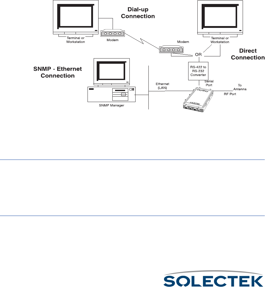
Accessing the SkyWay Bridge/Router
There are three ways to access the SkyWay Bridge/Router:
• Direct Connection.
Direct Connection.Direct Connection.
Direct Connection. Use a terminal that is directly connected to the unit's
RS-422 port. This is called the local console, and it allows you to directly
access all of the Skyway’s configuration and management screens.
• Dial-up Connection.
Dial-up Connection.Dial-up Connection.
Dial-up Connection. Use a dial-up modem attached to the SkyWay to access
the local console. Functionally, it is the same as being directly connected.
•SNMP Connection.
SNMP Connection.SNMP Connection.
SNMP Connection. Use an SNMP Manager to access most of the Skyway’s
configuration screens. The SNMP Manager accesses the SkyWay over Ether-
net or a SkyWay’s RF link with another SkyWay. For Configuration and Status
screens not accessible via SNMP, see “Appendix A: Run-time Menu Tree” on
page 175.
The following diagram shows these three methods:
For more information about connecting the SkyWay to a console, see “Connecting to
the Administration Console” on page 51.
Modem Settings for Dial-up Connection
To configure a
modem attached to
the SkyWay
1. Set the modem to Auto Answer.
2. Set the modem’s RS-232 port speed to Fixed. It cannot follow the connection
speed, because SkyWay’s serial port is a manually configurable fixed speed.
3. Set DTR to High to Always On. This is necessary for some modems.
To c o n f i g u r e t h e
Terminal for dialing
to the SkyWay
1. Set the terminal to type VT-100.
2. Set the baud rate to the SkyWay-configured baud rate (default is 115200 bps). To
change the SkyWay’s baud rate, go to “1.2.1.1 Serial Port Configuration” on
page 24.

Accessing the SkyWay Bridge/Router
23
3. Set the terminal to 8-bits, No Parity, 1 Stop Bit.
4. Dial the modem attached to the SkyWay.
Example AT
Commands
You may need to write a command line to configure your modem for use with the
SkyWay. The example command line below is listed for your convenience and is not
configured through a screen on the SkyWay. The following is an example of the AT
command settings for a USRobotics V.Everything modem attached to the SkyWay.
The AT command line reads: ATQ1&A0&B1&D0&F0&H0&R1S0=1&W
The above command line disables any flow control, fixes the speed of the serial port,
and disables any response codes back to the SkyWay unit. Make adjustments or addi-
tions to these settings based on your local configuration.
These change the default configuration; however, the modem should then boot from
the NVRAM settings.
Configuring the Serial Port and Serial Transceiver
Go to the 1.2.1.1 Serial Port Configuration, or 1.2.1.2 Serial Transceiver Configuration
screen.
Where…
Where…Where…
Where… Means…
Means…Means…
Means…
Q1 Suppress result codes
&A0 Don’t display ARQ result codes
&B1 Fixed DTE speed
&D0 Ignore DTR
&F0 Load no flow control template settings
&H0 Disable transmit data flow control
&R1 Ignore RTS
S0=1 Answer on first ring
&W Write to NVRAM

24
1.2.1.1 Serial Port Configuration
Field Name MIB Default Setting
Port Number [swSerialPortIndex] 1
The serial port number is 1.
Configuration Status [swSerialPortConfigSta-
tus]
On-line
Whether this port configuration initializes upon reset. On-line means the port
comes up as a serial port when the unit is reset; Off-line means the port does not
initialize upon reset.
Buffers [swSerialPortMaxBuffers] 80
Serial port buffers.
Transmit Buffers [swSerialPortTransDesc] 16
Serial port transmit buffers.
Receive Buffers [swSerialPortRecvDesc] 16
Serial port receive buffers.
Maximum Frame Size [swSerialPortMaxFrame-
Size]
512
Largest frame that can be transmitted vial the serial port
1.2.1.1 Serial Port Configuration
Port Number : 1
Configuration Status : On-line
Buffers : 80
Transmit Buffers : 12
Receive Buffers : 12
Maximum Frame Size : 512
\ - return to menu . - commands TAB - next available field ENTER - edit

Accessing the SkyWay Bridge/Router
25
1.2.1.2 Serial Transceiver Configuration
Field Name MIB Default Setting
Port Number [swSerialPortIndex] 1
The serial port number is 1.
Baud Rate [swSerialPortBaudRate] 115200
The baud rate of the local serial port.
Data Bits [swSerialPortDataBits] 8
The number of data bits for the serial port.
Parity [swSerialPortParity] NONE
The parity setting for the serial port.
Stop Bits [swSerialPortStopBits] One
The number of stop bits for the serial port.
1.2.1.2 Serial Transceiver Configuration
Port Number : 1
Baud Rate : 115200
Data Bits : 8
Parity : NONE
Stop Bits : One
\ - return to menu . - commands TAB - next available field ENTER - edit

26

27
Chapter 3:
Chapter 3: Chapter 3:
Chapter 3:
Preparing for Installation
Preparing for InstallationPreparing for Installation
Preparing for Installation
Since the Skyway bridge/router is a ruggedized device installed outside the building,
Solectek recommends spending some time planning the installation and testing the
configuration before permanently mounting the units.
This chapter contains the following information:
Before Installing ................................................................ 28
Safety Considerations ....................................................... 29
General Safety Guidelines........................................... 29
Electrical Safety Guidelines.......................................... 29
Pre-installation Procedures................................................ 30
Site Considerations..................................................... 30
Bench Test ................................................................. 32

28
Before Installing
To complete your SkyWay installation, you need the following items:
• A pair of cellular telephones or walkie-talkies, so installers can communicate
when aligning SkyWay antennas during the installation process
• (Optional: Needed only if you find it absolutely necessary to cut the indoor
connectors off to accommodate pulling the cable through conduit):
•Ethernet cable: an RJ-45 cable crimper to terminate the RJ-45 connection
to the Ethernet LAN during the installation process
•Serial cable: a small screwdriver to disassemble the DB-9 case, a pin
removal extractor tool or a replacement DB-9 jack
•Power cable: a soldering iron
For pin-out information, see “Appendix C: Interface Specifications and Pinouts”
on page 181.
• VT-100 console or a workstation with VT-100 emulation capability and termi-
nal emulation software such as Hyperterm™ or Procomm™ to configure the
SkyWay Bridge/Router
• (Optional) a modem, if you want to operate the SkyWay Bridge/Router
through a dial-up connection
• 13 mm hex socket wrench for mounting bracket
• Slotted screw driver for mounting clamps

Safety Considerations
29
Safety Considerations
The following sections provide guidelines to ensure your safety when installing and
working with the SkyWay Bridge/Router.
General Safety Guidelines
Observe the following guidelines to ensure general safety:
• Keep tools away from walk areas where you and others could trip over them.
• Do not wear loose clothing that could get caught in the chassis mounting hard-
ware. Fasten your tie or scarf and roll up your sleeves.
• Wear safety glasses when working under any conditions that might be hazard-
ous to your eyes.
• Do not perform any action that creates a potential hazard to people or makes
the equipment unsafe.
Electrical Safety Guidelines
Observe the following electrical guidelines when working on the SkyWay Bridge/
Router.
• Do not work on the system or connect or disconnect cables under these con-
ditions:
• during a thunderstorm
• when wearing a wool sweater or other heavy wool clothing
• when power is applied
• Do not touch the SkyWay power supply when the power cord is connected.
Because the SkyWay Bridge/Router does not have a power switch, line volt-
ages are present within the power supply when the power cord is connected
to the Bridge/Router.
• The SkyWay’s Bridge/Router relies on the building’s installation for short-circuit
(overcurrent) protection. Make sure that a fuse or circuit breaker not larger
than 120 VAC, 15A U.S. (240 VAC, 10A international) is used on the phase
conductors (all current-carrying conductors).
• Before working on the SkyWay chassis, unplug the power cord from the AC
outlet or disconnect the fuse or circuit breaker.
• Locate the emergency power-off switch for the AC source connected to the
SkyWay Bridge/Router. If an electrical accident occurs, use this switch to turn
off power to the bridge.
• Identify possible hazards in your work area, such as moist floor, ungrounded
power extension cables, and missing safety grounds. Do not work alone if
potentially hazardous conditions exist.

30
Pre-installation Procedures
Planning and feasibility studies are critical to successfully integrate the SkyWay Bridge/
Router with your network. There are additional factors, for example, Radio Line of
Sight and overall RF environmental issues, which must be taken into account for wire-
less connectivity.
Site Considerations
Deploying a successful network requires feasibility studies and careful planning, particu-
larly for wireless connectivity solutions where additional factors must be considered.
Radio Line of Sight and overall RF environment must be assessed and documented to
assist in determining the initial installation as well as providing a baseline for future RF
environmental measurements when suspected local RF environment changes occur.
Step One: Assess Your Network Requirements
Solectek recommends the following steps in determining the feasibility of a wireless
internetworking solution using Solectek wireless bridges and routers:
• Identify, list and classify the data resource centers by type and number of users
• Layout the topology of voice, data and video networks indicating bandwidth
requirements, protocols, and media of each network segment.
• Plan and layout the IP addressing scheme for IP and IPX networks
• Ensure all protocols deployed in the planned network, including planned wire-
less segments, can be encapsulated in Ethernet frames 802.1d, 802.3, and
802.2.
• Identify protocols and network segments which will require encapsulation in IP
packets and consequent routing.
Step Two: Map Wireless Network Pre-Design
You then provide details about locations to be connected, for example, building-to-
building, or server-to-ISP.
• Identify and mark the locations of the main nodes of the network on a geo-
graphical map of the region. Attach full street addresses and building character-
istics to each location.
• Gather site coordinates (latitude and longitude) for each location
• Use the site coordinates to determine optimal geographical layout of desired
link paths for wireless network segments, and complete the wireless network
geographical map.
• Determine minimum antenna height requirement for each location, which
guarantees that in each link’s path, at least 60% of Fresnel zone is unob-
structed.

Pre-installation Procedures
31
Step Three: Perform a Site Survey
In this step, you assess the Line of Sight and RF environmental factors.
• Check for the existence of competing RF signals, using a spectrum analyzer.
• Detect and measure the potential sources of interference in selected RF bands
for each site
• Mark the direction and nature of detected RF interference on the wireless net-
work map (created in step two).
• Determine the height of obstacles (trees, buildings, highways) in each link’s
path.
Step Four: Finalize the Design
The final step includes adjusting your plan and selecting equipment.
• Adopt changes in the network layout to overcome RF interference, and to
guarantee the minimum required bandwidth for each link.
• Adjust antenna height requirements based on identified obstacles in the site
survey.
• Select the antenna types for each site, based on the link distance and minimum
antenna co-location requirements.
• Select an RF channel and antenna polarity plan for each link.
• Select cable types and lengths.

32
Bench Test
Solectek strongly recommends using the Bench Test for testing the SkyWay Bridge/
Router prior to installing it in its permanent location. The test provides a means to
install and configure the equipment to your requirements. It allows you to become
familiar with the equipment’s operation and capabilities in a user-friendly environment.
Installers who bench test all equipment and configurations have a significantly higher
success rate during field installation than those who skip the test.
The following are required for the bench test:
• At least 2 SkyWay units
• SkyWay power cable and AC/DC converter
• Console cable and RS-422 to RD-232 converter
• Test antenna for each SkyWay RF port
• Two terminals or workstations with VT-100 emulation capability (one for each
Skyway), or one workstation with two RS-232 ports to accommodate two
SkyWays (see “Step One: Connecting Components” on page 33).
Minimum Configuration Settings and Factory
Defaults for Bench Test
•RF frequency
RF frequencyRF frequency
RF frequency: Use the most efficient RF frequency for your SkyWay as deter-
mined during the site survey.
• Tap Value
Ta p Va lu eTa p Va lu e
Tap Value: During installation, the installer decides on an appropriate tap value
for your SkyWay so that there is no interference with other SkyWay traffic.
•Mode
ModeMode
Mode: Designate one SkyWay as the base station, and the other as the sub
station.
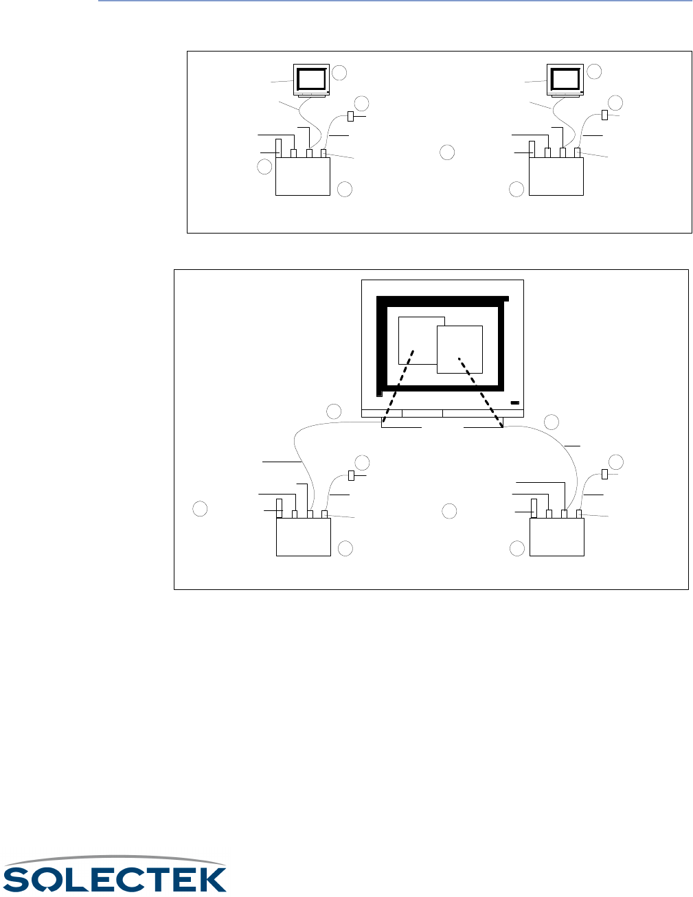
Bench Test
33
Performing the Bench Test
Step One:
Connecting
Components
Use the following to connect the components in a bench test environment. There are
two possible scenarios:
1. Position two SkyWays side by side.
2. Connect the DC power cables to the rear panels of the SkyWays. Connect the
other ends to two AC/DC converters. Plug in the converters to power.
3. Connect two console cable connectors to the rear panels of the SkyWays. Con-
nect the opposite ends (RS-422/RS-232 converters) to the COM1 ports of two
computer workstations or to the COM1 and COM2 ports on one computer
workstation.
4. Connect the test antenna to the RF ports of the SkyWays.
AC/DC converter
DC Power
connector
Power cable
Test Antenna
Console cable
Terminal or PC
Ethernet Port Serial port
DC Power
connector
1 1
2
SkyWay 2
AC/DC converter
Power cable
Test Antenna
Console cable
Terminal or PC
Ethernet Port Serial port
3
4
2
3
4
Scenario 1: Two SkyWay units connected to two terminals or PCs
AC/DC converter
DC Power
connector
Power cable
test antenna
Console cable
Ethernet Port
Serial port
DC Power
connector
1 1
2
SkyWay 2
AC/DC converter
Power cable
test antenna
Console cable
Ethernet Port
Serial port
3
4
2
3
4
Scenario 2: Two SkyWay units Connected to One PC
PC running
Hyperterm
COM1
COM2
SkyWay 1
SkyWay 1

34
Step Two:
Preparing the
Computer
Workstation for the
Bench Test
Use the following steps to set up the administration console that you will use to moni-
tor and configure the test. The following shows an example using a PC with Hyper-
term set for VT-100 terminal emulation.
1
2
3
4
Start a Hyperterminal Session:
Under Windows, click Start,
Accessories, Hyperterminal.
Set up COM 1:
In Connection Description:
Select an icon
Enter a name - for example:
COM1 - SkyWay 1;
COM2 - SkyWay 2
Connect to COM1:
In Connect To Dialog, at
Connect Using:
Select COM1
Set up COM1 properties:
In COM1 Properties: choose
these port settings:
BPS - 115200
Data bits - 8
Parity - none
Stop bit - 1
Flow control - none
Set VT-100 Emulation:
In Hyperterminal, click File--
Properties--settings tab
Choose VT-100 Emulation
Click ASCII button
Uncheck Wrap lines.... box.
5
6
DONE
Repeat Steps 1 - 5 for the
second SkyWay:
lf you are using only one PC, set
up COM 2 port on the PC.
If you are using two terminals or
PCs, set up the other terminal or
COM 1 on the other PC.

Bench Test
35
1. Start Hyperterminal on one of the workstations. (For Windows, go to Start|Acces-
sories|Hyperterminal.)
2. In the Connection Description
Connection DescriptionConnection Description
Connection Description box, select a name and icon.
3. In the Connect To
Connect ToConnect To
Connect To box, at “Connect using”, select COM 1.
4. In the COM 1 Properties
COM 1 PropertiesCOM 1 Properties
COM 1 Properties box, select the following port settings:
• Bits per second: 115200
• Data bits: 8
• Parity: None
• Stop: 1
• Flow control: None
5. From the Hyperterminal top menu, select File|Properties|Settings tab, and do the
following:
• From the Emulation menu, select “VT-100”.
• Type the ASCII setup button, and clear the wrap lines
wrap lineswrap lines
wrap lines box.
6. Start Hyperterminal again on the same workstation to open a new screen (if you
have connected the SkyWay to two COM ports), or start Hyperterminal on a sec-
ond workstation linked to the second SkyWay. Do the following:
• In the Connection Description
Connection DescriptionConnection Description
Connection Description box, select a new name and icon.
• In the Connect To
Connect ToConnect To
Connect To box, at “Connect Using,” select COM 2 if you are using one
computer and two com ports. If you are using a second workstation, select
COM 1.
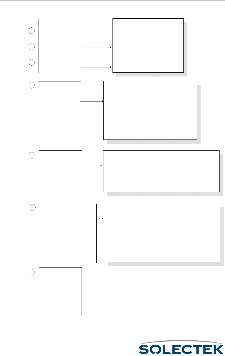
36
Step Three:
Configuring the
Bench Test
Use the following steps to set the parameters for running the bench test.
Configure the RF Sub
Diagnostic Port:
Go to the other
Hyperterminal blank screen
OR the other terminal.
Repeat steps 1 thru 6,
except the Port Type = RF
Sub Diagnostic Port for
each sub station unit.
1.2.3.2 RF Diagnostic Port Configuration
Port Number 3
Configuration Status On-line
Port Type RF-DLC Base Diagnostic Port
Max Buffers 800
Transmit Buffers 240
Receive Buffers 180
Maximum Frame Size 3200
Record Type Valid
1
7
2
3
4
6
Login to SkyWay1:
Go to the first Hyperterminal
blank screen (this will be the
Base station).
Press Enter to bring up the
SKYWAY Login Screen.
Enter "Solectek" as the
default for both username
and password.
Cycle the port:
Go to screen 2.2.1Generic Port and
Status Control
Port Number = 3
Port Type = RF-DLC Base Diagnostic
Admin Status = Cycle
Type
Kt
to write the changes and
cycle the port. After a few seconds,
Operation Status changes from
"Transitioning...
Up" to "Up Port."
SkyWay
Model_xxx
Version 1.0
Solectek Corporation
Copyright 1999 - All Rights Reserved
System Name :
System Location :
User Name :
Password :
Configure the RF Base
Diag Port:
At the Main Menu, type
1232 to get to this screen
Port Type=RF Base Diag
Type .W to write the
changes to the database
2.2.1 Generic Port Status and Control
Port Number 3
Port Type RF-DLC Base Diagnostic Port
Port Baud Rate 2 Mbps
Largest Datagram Size 1492
Physical Address 00:00:c4:1cc:91:45
Administrative Status Cycle
Operational Status Up Port
Last Status Change 0.01 seconds
Maximum Transmit Buffers 512
Configure the RF Sub
Diagnostic Port:
Go to screen 1.2.3.3 to set
the RF Transceiver values
based on your Site Survey.
Type .W to write the
changes to the database
5 1.2.3.3 RF Transceiver Configuration
RF Port RF Frequency RF Data Rate Scrambler Tap
---------- -------------------- ------------------ ---------------------
3 2468 2 Mbps 72

Bench Test
37
1. Go to the first Hyperterminal blank screen (which will serve as the “Base”).
2. Ty p e E N T E R
ENTERENTER
ENTER to bring up the Login screen.
3. Enter “Solectek” as the default for both username and password.
Note To access a screen from another non-menu screen, press . followed by the screen
number and press Enter, or return to the main menu and type the screen number. For
tips on navigating the screens, see “ Navigating Through Menus and Screens” on
page 13.
4. The Main Menu for Run Time Application will appear. Type 1232 to access the RF
Diagnostic Port Configuration screen. Make the following changes (setting may
already be correct):
• Port Type: RF-DLC Base Diagnostic Port
• RF data rate: depends on configuration setting (2, 5.5 or 11 Mbps)
Ty p e . W to apply the change. Return to the Main Menu.
5. Press 1233 to access the RF Transceiver Configuration screen. Configure the fol-
lowing values, based on information obtained during the site survey process:
•RF Frequency
• RF Data Rate
•Scrambler Tap
Ty p e .W to apply the change.
6. Press 221 to access the Generic Port Status and Control screen. Make the follow-
ing changes:
•Port Number: 3 (RF Port)
• Administrative Status: Install Port
Ty p e .W to apply the change. Make sure Administrative Status
Administrative StatusAdministrative Status
Administrative Status changes to Up Port.
This demonstrates that the port is active.
7. Go to the sub station screen. Repeat steps 2 through 6. In the RF Diagnostic Port
Configuration screen (1232; step 4), Port Type
Port TypePort Type
Port Type must be RF-DLC Sub Diagnostic
Port. Do this for each sub station included in the bench test.

38
Step 4: Starting the
Bench Test
The two SkyWay units will now transmit information back and forth to test wireless
performance.
1
2
4
3
4.1 RF Base Radio Test
* Note - diagnostic driver must be installed *
RF Port Number 3
Test Timeout (NSL List) Milliseconds
Test To Run Single Frame Ping Pong Mode
Number of Frames or Bursts, 1 to 65535 or 0 for continuous : 0
Frame Length or Maximum Burst Size, 3 - 3200 bytes : 1530
Set up the Base Station Test:
Go to SkyWay1 (the base
station).
Type
QN
to access this
screen
Test to Run = Single Frame
Ping Pong Mode
Test Timeout = depends on
the bandwidth:
36 ms for 2 Mbs
12 ms for 5.5 Mbs
9 ms for 11 Mbs
Type
Kª
to write the changes
Set up the Sub Station Test:
Go to SkyWay2 (the sub
station).
Type
QO
to access this
screen
Test to Run = Single Frame
Ping Pong Mode
Type
Kª
to write the changes
4.2 RF Sub Radio Test
* Note - diagnostic driver must be installed *
RF Port Number 3
Test to Run Single Frame Ping Pong Mode
Monitor the test on the Sub:
You are still at SkyWay2 (sub).
Type
OOQ
to access this
screen
Type
Kw
to clear the
statistics
Type
Kj
to enter monitor
mode
5
2.2.4 RF Port Status
Port Number 3
Port Type Sub Port Diagnostic
Port Status On-line
RF data rate 2 Mbps
RF Channal 2468 Mhz
Bytes IN 0 OUT 0
Frames IN 0 OUT 0
Discards IN 0 OUT 0
Digital Phase Lock Loop
Frame Length Violation
Non Octet Aligned Frame
Abort Sequence
CRC Error
Overrun
Carrier Detect Lost
Underrun
CTS Lost
Monitor the test on the Base:
Go to SkyWay1 (the base
station)
Repeat Step 5 - the Port Type is
Base Port Diag
6
7
Check the results:
Wait at least 30 seconds for an
accurate reading
Total the sum of the errors in
the errors column. The sum
should be less than 1% of the
total number of frames
received (IN).
8
9
Terminate the test:
Go to screen 4.1.2 and change
Test to Run = Terminate Test
Type
Kt
to write the change

Bench Test
39
1. Return to the base station.
2. Access screen 4.1 Base Radio Test. Change the following:
• Test to Run: Single Frame Ping Pong Mode
This mode means that the base station sends out frames one at a time, and the
sub station returns them one at a time.
• Test Timeout to the appropriate ms selection. Select 36 ms for 2 mb, 12 ms
for 5.5 mb, and 9 ms for 11 mb.
3. Go to the sub station.
4. Access screen 4.2 (Sub Radio Test). Make the following change:
Test to Run: Single Frame Ping Pong Mode
5. Access the 224 screen (RF Port Status).
•Type .Z to zero test values.
•Type .M to monitor.
You should see the numbers incrementing in the bytes and frames row, reflecting
transmission of frames back and forth between base and sub. Wait at least 30 sec-
onds to get an accurate reading.
6. In the errors column on the lower left of the screen, total the sum of the errors.
The sum should be less than 1% of the total number of frames received (in the
“IN” location). To terminate the test, return to the “Base” screen, access screen
224, and change Test to Run
Te s t t o R u nTe s t t o R u n
Test to Run to Terminate.
7. Go to the other screen (“Base”).
8. Access the 224 screen (RF Port Status).
• Press .Z to zero the data.
• Press .M to enter monitor mode. Wait at least 30 seconds to get an accurate
reading.
• In the errors column on the lower left of the screen, total the sum of the
errors. The sum should be less than 1% of the total number of frames
received (in the “IN” location). To terminate the test, access screen 224, and
change Test to Run
Te s t t o R u nTe s t t o R u n
Test to Run to Terminate.
Step 5: Configure
the SkyWay for
Installation
To complete the configuration process, go to “Chapter 5: Configuring and Managing
SkyWay” on page 57.

40

41
Chapter 4:
Chapter 4: Chapter 4:
Chapter 4:
Installing Skyway
Installing SkywayInstalling Skyway
Installing Skyway
Once you have performed a successful bench test and configured the units to your sat-
isfaction, you are ready to install and connect them.
This chapter contains the following information:
Mounting the SkyWay Unit ............................................... 42
Mounting to a Mast..................................................... 42
Mounting to a Wall ..................................................... 44
Setting Up the Antenna..................................................... 45
Grounding Skyway and the Antenna.................................. 47
Connecting Cabling .......................................................... 48
Connecting an Antenna .............................................. 49
Connecting to Power ................................................. 50
Connecting to the Administration Console.................. 51
Connecting to Your LAN ............................................ 53
Routing Connected Cables ......................................... 48
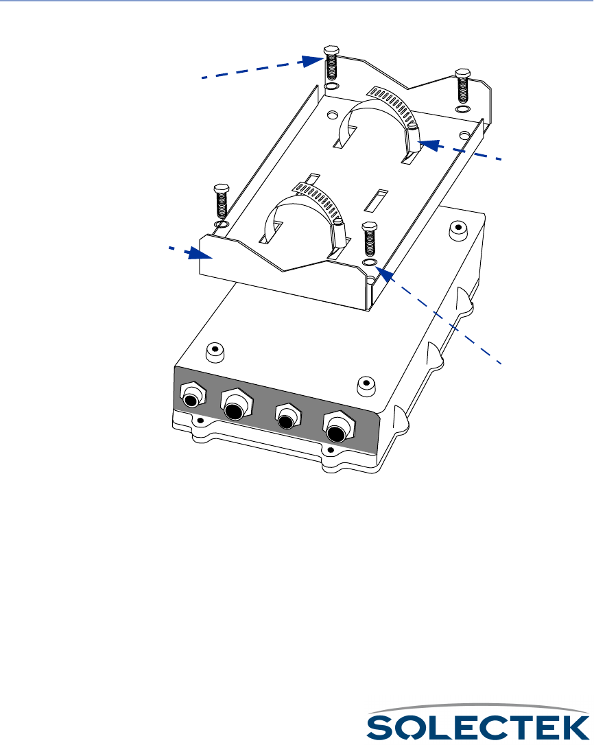
42
Mounting the SkyWay Unit
Mount The SkyWay Bridge/Router to an outdoor mast or wall.
Mounting to a Mast
To o l s :
To o l s :To o l s :
To o l s :
• 13 mm hex socket wrench
• Slotted screwdriver
To m o u n t t h e
SkyWay to a mast:
1. Place the mast-mounting bracket on a table with the flat side down.
Use the third central pair
of slots for seating a third
clamp if you want extra
clamp security.
2. Thread two clamps into the outside pair of slots on the bracket. Make sure to
thread them in the same direction.
3. Place the SkyWay face down. Place the bracket and clamp assembly over the rear
of the SkyWay so that the four mounting holes align.
4. Place one spring lock washer (P/N 1225201) on each mounting bolt.
5. Using a 13 mm hex socket wrench, tighten a bolt and washer into each hole of the
bracket to a maximum torque of 15-20 ft-lbs (to prevent stripping).
P/N 1225001
P/N 1225001P/N 1225001
P/N 1225001
P/N 1225501
P/N 1225501P/N 1225501
P/N 1225501
P/N 1225401
P/N 1225401P/N 1225401
P/N 1225401
P/N 1225201
P/N 1225201P/N 1225201
P/N 1225201

Mounting the SkyWay Unit
43
6. Position the bracketed SkyWay against the mast with the connectors facing down-
ward.
Note: The mast should be a minimum of 1 in. (25.4 mm) outside diameter.
7. Feed the end of each clamp around the mast into the locking mechanism at the
other end. Using a slotted screwdriver or nut driver, tighten the clamp screws to a
maximum torque of 45 ± 5 in-lbs.
CAUTION: The mast to which you mount the Skyway and/or antenna should be
grounded. If the mast is not grounded, see “Grounding Skyway and the Antenna” on
page 47.
Connector side down
Connector side downConnector side down
Connector side down
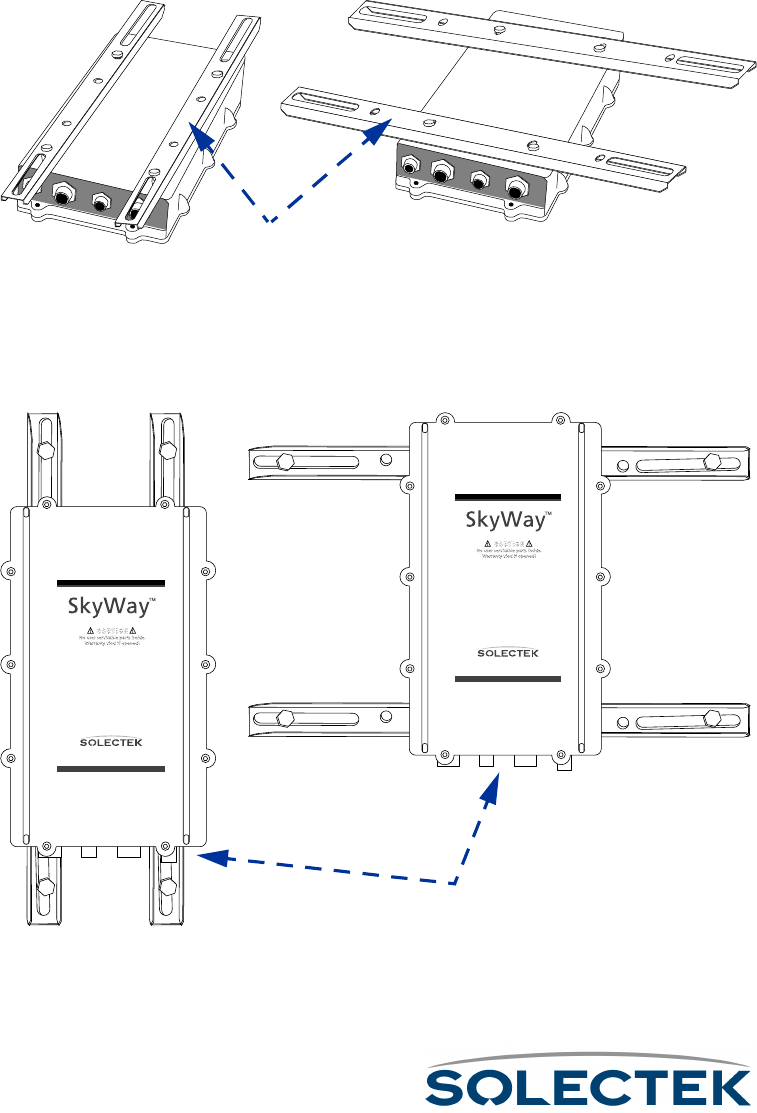
44
Mounting to a Wall
The wall mount kit is optional and may be purchased separately.
To o l s :
To o l s :To o l s :
To o l s :
• 13 mm wrench
1. Place the SkyWay face down.
2. Align the two brackets over the SkyWay unit’s bolt holes, either along the length or
width of the unit.
3. Insert bolts and tighten with a 13 mm wrench.
Note: The bolts can be found in the Mast Kit, which is always shipped with SkyWay.
4. Fasten the SkyWay to the wall using the slider slots and bolts (not supplied), making
sure the SkyWay’s connectors face downward.
CAUTION: The surface to which you mount the Skyway and/or antenna should be
grounded. If the surface is not grounded, see “Grounding Skyway and the Antenna” on
page 47.
P/N 1225101
P/N 1225101P/N 1225101
P/N 1225101
www.solectek.com
www.solectek.com
Connector side down
Connector side downConnector side down
Connector side down

Setting Up the Antenna
45
Setting Up the Antenna
Skyway requires an RF antenna to receive and transmit signal effectively.
Selecting the Antenna
Solectek supplies one of several different antennas, including both sectoral and omni
models. Solectek’s systems engineers will assist you with antenna selection, taking into
account factors such as usage (point-to-point or multi-point), distance to substations,
and interference from nearby antennas.
Apart from the two omnidirectional antennas (7002301 6 dBi and 7002401 11 dBi), all
Solectek antennas are designed to be used as bridge antennas between two networks
or for point-to-point communications in the ISM band (2.4 GHz) only.
Before You Mount the Antenna
Follow these guidelines before and during installation of the SkyWay antennas:
1. Avoid reflective environments:
Avoid reflective environments: Avoid reflective environments:
Avoid reflective environments: Where possible, avoid mounting antennas in a
“reflective environment” (i.e., near objects that can reflect radio energy back to the
antenna). Signal reflections from nearby objects are seen as noise by radio trans-
ceivers, and can adversely affect the range or quality of your wireless link. Exam-
ples of such objects include the following:
• Trees or bushes
•Buildings
• Air conditioning units and ductwork
•Other radio antennas
• Building structures made of any material such as steel, brick, or wood
• Construction vehicles and equipment
2. Follow precise and safe handling procedures:
Follow precise and safe handling procedures:Follow precise and safe handling procedures:
Follow precise and safe handling procedures:
• Do not perform antenna installation by yourself. Some antennas are large and
hard to handle, especially when changing polarity or performing the final
mounting on the mast. You need a second person to align the antenna, so try
to schedule as much antenna work as possible when at least two workers are
available.
• Use a bubble level (carpenter’s level) to make sure all antennas are level with
the horizon. See Appendix K for details related to specific antennas. For anten-
nas mounted to the wall, you may need additional spacers or washers to
obtain a level installation.

46
3. Mount antennas securely:
Mount antennas securely: Mount antennas securely:
Mount antennas securely: A small movement of the antenna caused by an insecure
mount or weak mast results in a huge sweep at the other end of the link miles
away.
• Make sure the antenna is bolted securely to the mast.
• Always use appropriate guy wires (see your local building codes for recom-
mendations and requirements).
• Weight non-penetrating roof mounts securely with concrete blocks or other
ballast.
4. Handle the antenna RF cable carefully:
Handle the antenna RF cable carefully: Handle the antenna RF cable carefully:
Handle the antenna RF cable carefully: Maintain a 12-inch bend radius if possible.
Do not walk on or kink the cable. A kinked cable causes severe signal attenuation,
and can cause the link to fail.
Mounting the Antenna
Connect one of the available antennas to the mast using the appropriate clamping or
bolting apparatus. For more information, see “Appendix K: Skyway Antennas” on
page 213.

Grounding Skyway and the Antenna
47
Grounding Skyway and the Antenna
Warning: Ungrounded or improperly grounded antennas constitute a hazard to personnel and
Ungrounded or improperly grounded antennas constitute a hazard to personnel and Ungrounded or improperly grounded antennas constitute a hazard to personnel and
Ungrounded or improperly grounded antennas constitute a hazard to personnel and
equipment. A lightning strike on or near an improperly grounded antenna can cause
equipment. A lightning strike on or near an improperly grounded antenna can cause equipment. A lightning strike on or near an improperly grounded antenna can cause
equipment. A lightning strike on or near an improperly grounded antenna can cause
severe injury or death as well as equipment destruction. Any Solectek equipment
severe injury or death as well as equipment destruction. Any Solectek equipment severe injury or death as well as equipment destruction. Any Solectek equipment
severe injury or death as well as equipment destruction. Any Solectek equipment
damaged by lightning is considered to have been damaged by an Act of God, and is not
damaged by lightning is considered to have been damaged by an Act of God, and is not damaged by lightning is considered to have been damaged by an Act of God, and is not
damaged by lightning is considered to have been damaged by an Act of God, and is not
covered under warranty.
covered under warranty.covered under warranty.
covered under warranty.
Solectek antennas (2.4 GHz) and the SkyWay Bridge/Router do not require additional
grounding when mounted on antenna masts that are properly grounded per local elec-
trical and building codes.
Supply grounding if the SkyWay and its antenna are mounted on a non-penetrating
roof mount, a wall, or an ungrounded wooden mast. In these cases, attach one end of
a bond wire to one of the bolts on the SkyWay bracket. Attach the other end to
another mast (properly grounded), a building ground, or an NEC ground.
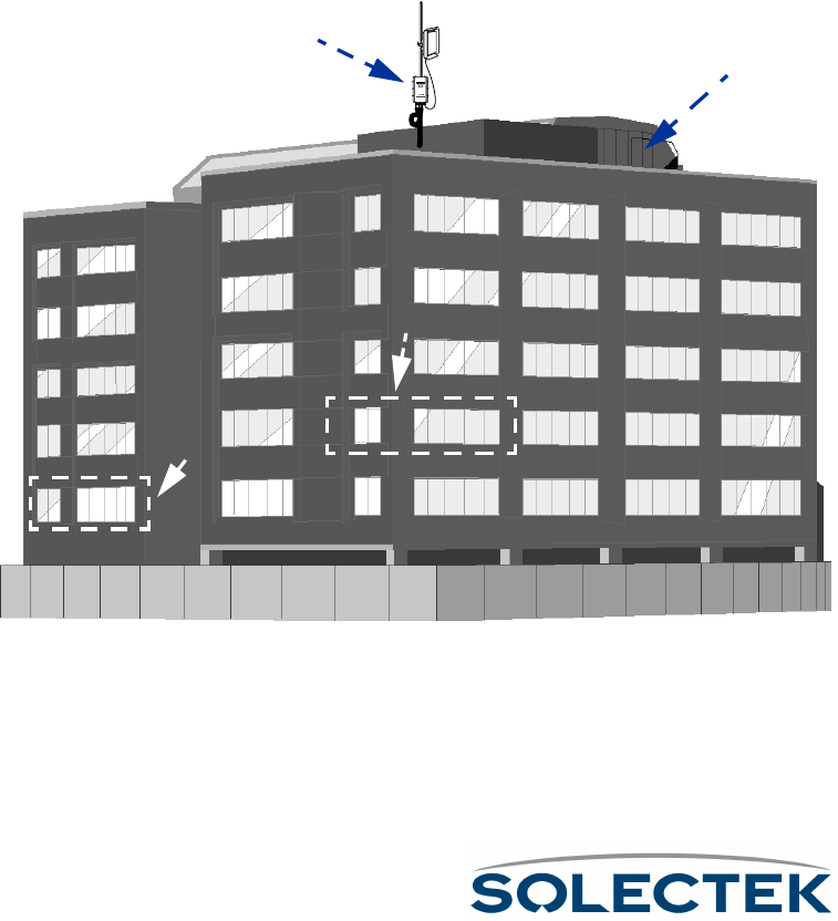
48
Connecting Cabling
The SkyWay connects to the antenna by means of a LMR-400 RF cable.
The SkyWay connects to power and to the terminal, terminal emulator or LAN by
means of three cables:
•power
•console
• data (Ethernet copper or fiber)
The three cables route into the building.
Routing Connected Cables
Before you begin connecting the SkyWay, consider where the cables should be routed.
within the building. SkyWay’s design enables you to route each cable to its most logi-
cal/convenient location. These locations may not be in the same room or even on the
same floor. For example, it may make the most sense to route the power to a utility
room on the top floor, the console to a secured room on the second floor, and the
Ethernet to your LAN room on the first floor:
The length of the cables you ordered determines the maximum distance for each
connection.Be sure to secure the cables to the mast at intervals to protect the cables
and the connection.
www.solectek.com
Utility Room for Power
Utility Room for PowerUtility Room for Power
Utility Room for Power
Secured Room for Console
Secured Room for ConsoleSecured Room for Console
Secured Room for Console
LAN
LANLAN
LAN
room
roomroom
room
SkyWay
SkyWaySkyWay
SkyWay
mount
mountmount
mount
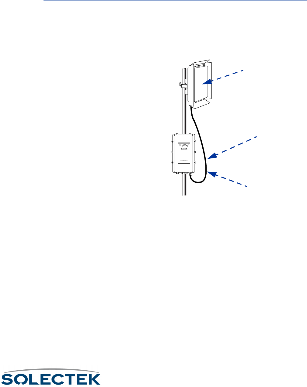
Connecting Cabling
49
Connecting an Antenna
The LMR-400 RF cable connects the SkyWay with the antenna above it on the mast.
To connect an RF
cable:
1. Making sure the threads are properly aligned, tighten the cable’s connector bolt
snugly over the SkyWay’s RF connector port using a 13/16 in wrench. Hand-
tighten another 1/4 turn to lock it in place.
2. Similarly connect the other end of the RF cable to the antenna’s connector.
Note: Allow sufficient slack in the cable for a maximum turning radius of 1 ft.
3. Seal the connections to both the antenna and the SkyWay with “Coax Seal”
(P/N 10702) to prevent water entry.
www.solectek.com
Slack for 1 ft turning radius
Slack for 1 ft turning radiusSlack for 1 ft turning radius
Slack for 1 ft turning radius
Antenna
AntennaAntenna
Antenna
LMR-400 cable
LMR-400 cableLMR-400 cable
LMR-400 cable
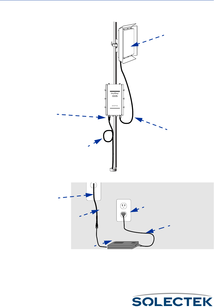
50
Connecting to Power
SkyWay requires DC power to operate. Solectek supplies an AC-to-DC converter
and a weather-rated DC power cable.
To c o n n e c t S k y Wa y
to power:
1. Connect the power cable’s 3-pin connector to the SkyWay power port. Plug in
and lock clockwise.
2. Connect the opposite (indoor) end to the supplied AC/DC converter.
Note: For extra power protection, plug the AC power cord into a UPS (200 W
minimum).
www.solectek.com
Power port
Power portPower port
Power port
Antenna
AntennaAntenna
Antenna
LMR-400 cable
LMR-400 cableLMR-400 cable
LMR-400 cable
Drip loop and
Drip loop andDrip loop and
Drip loop and
Cable slack
Cable slackCable slack
Cable slack
Conduit
Conduit Conduit
Conduit
exit
exitexit
exit
or routing
or routingor routing
or routing
AC source
AC sourceAC source
AC source
Cable from roof
Cable from roofCable from roof
Cable from roof AC power cord
AC power cordAC power cord
AC power cord
AC/DC converter
AC/DC converterAC/DC converter
AC/DC converter

Connecting Cabling
51
Connecting to the Administration Console
Use this connection to:
• make and apply configuration settings to the unit
• monitor performance
• obtain transmission statistics
Solectek supplies an RS-422 weather-rated cable and an RS-422-to-RS-232 converter
for connecting to a serial communications port on the console or modem.
Connect a terminal directly to the unit's RS-422 port to provide secure access for a sin-
gle console.
Note: You can use a modem to provide remote console access to all of SkyWay’s configura-
tion features. You may also use SNMP Manager on a workstation connected to the
LAN to access most of Skyway’s configuration objects. For security reasons, however,
not all SkyWay’s features are available using SNMP.
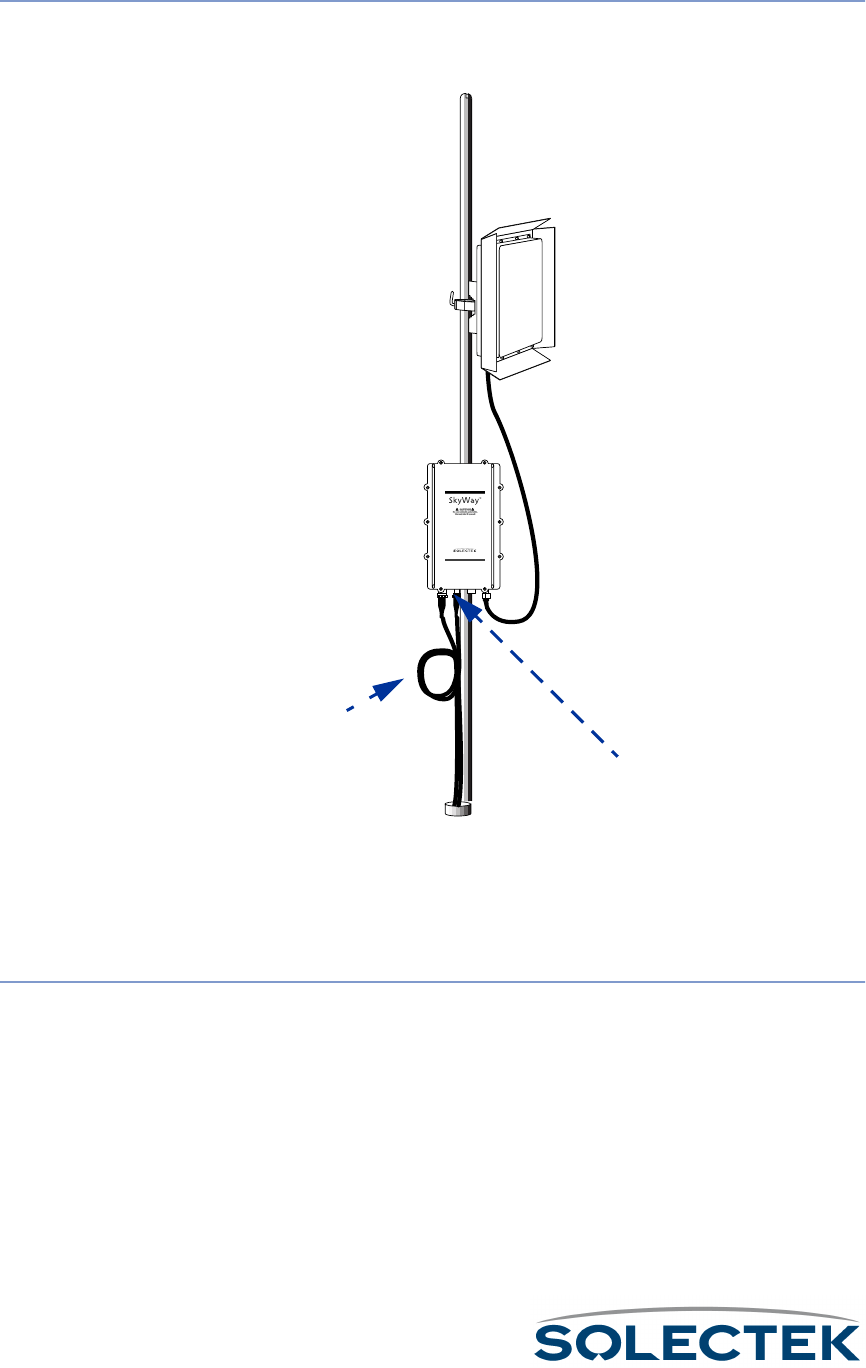
52
To c o n n e c t d i r e c t l y
to a administration
console:
1. Connect the console cable’s 6-pin connector to the SkyWay console port. Plug in
and lock clockwise.
2. Route the cable to the console, being sure to create a drip loop.
3. Connect the cable at the opposite (indoor) end of the console cable (DB-9 con-
nector) to the RS-422 converter, then to the serial communication port on the
console terminal or terminal emulator.
To c o n n e c t t o a
dedicated modem
and data line:
1. Connect and route the console cable as described above, except that you will con-
nect the cable to a modem, rather than the terminal or terminal emulator.
2. Connect a standard phone cable from the modem to the dedicated data line wall
jack. For more information on configuring the modem and accessing the SkyWay
remotely, see “Accessing the SkyWay Bridge/Router” on page 22.
www.solectek.com
Administration Console
Administration ConsoleAdministration Console
Administration Console
port
portport
port
Drip loop and
Drip loop andDrip loop and
Drip loop and
Cable slack
Cable slackCable slack
Cable slack
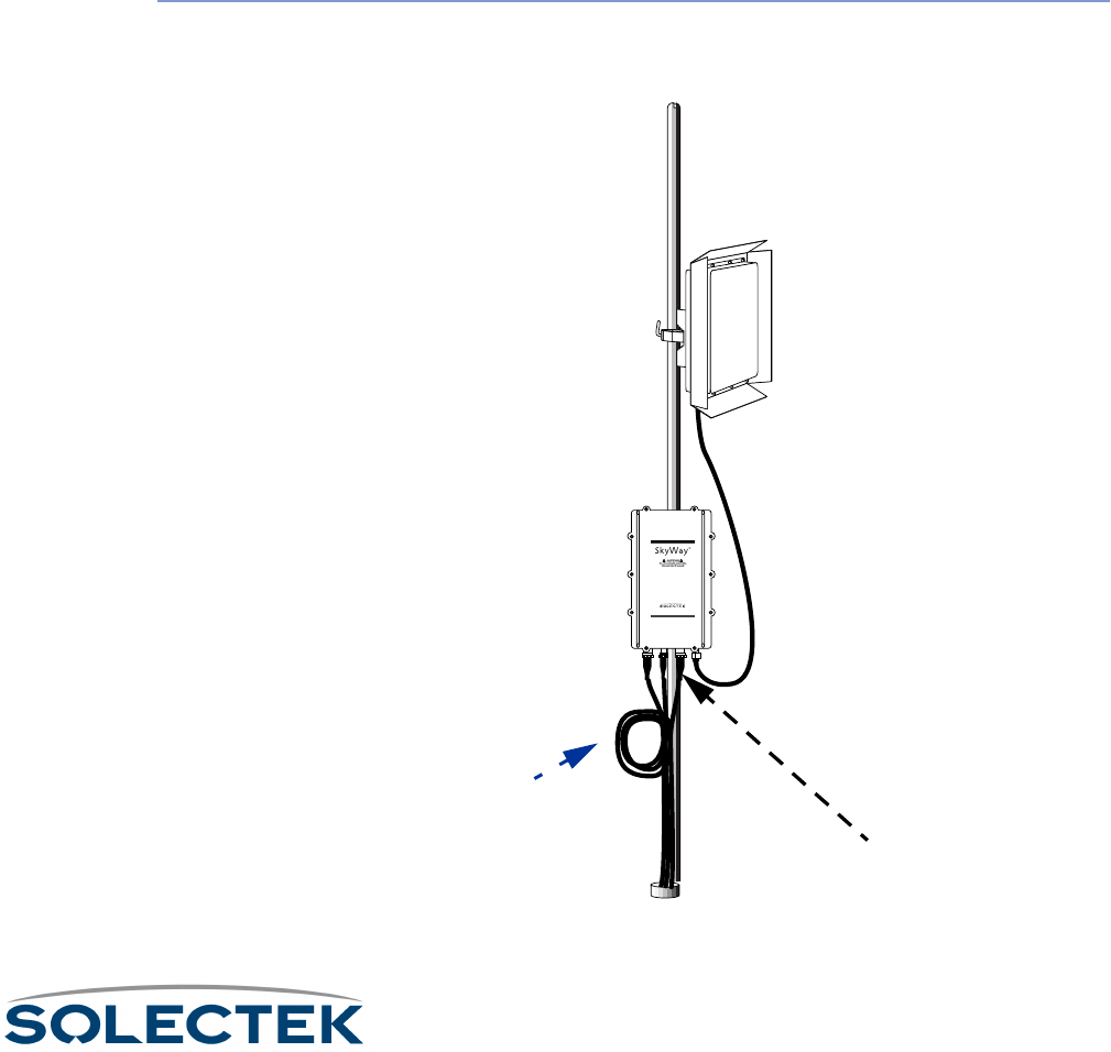
Connecting Cabling
53
Connecting to Your LAN
Connect the SkyWay to your LAN via copper or fiber optic cable.
Copper cable. The 10 Base-T/100 Base-TX (twisted pair) cable is available in 100,
200, and 300 foot lengths. This cable is terminated on the indoor side with a standard
RJ-45 connector and is intended to be connected to an Ethernet hub or switch. If a
cable length of longer than 300 feet is needed, you must order the SkyWay configured
to use a fiberoptic LAN connection. See “Fiberoptic cable” on this page for more infor-
mation.
Fiberoptic cable. Fiberoptic cable is available in longer lengths. Fiberoptic cable
transmission is not affected by the noise that can affect a copper cable, because electri-
cal transmission is converted into optical transmission. This cable is terminated on the
indoor side with a standard S/C fiberoptic connector and is intended to be connected
to a fiberoptic port on an Ethernet hub or switch.
To connect an
Ethernet cable:
1. Connect the Ethernet cable’s 8-pin connector (10 Base-T/100 Base-TX) or 2-pin
connector (100 Base-FX) to the Ethernet port. Plug in and lock clockwise.
2. Route the cable to the console, being sure to create a drip loop.
www.solectek.com
Ethernet port
Ethernet portEthernet port
Ethernet port
(copper or fiber)
(copper or fiber)(copper or fiber)
(copper or fiber)
Drip loop and
Drip loop andDrip loop and
Drip loop and
Cable slack
Cable slackCable slack
Cable slack

54
3. Connect the opposite (indoor) end of the Ethernet cable to the appropriate Ether-
net port (RJ-45 or S/C) on your LAN hub or switch.

Antenna Alignment and RF Link Verification
55
Antenna Alignment and RF Link Verification
Once the system is installed and the antennas are mounted, you must ensure that you
have proper antenna alignment to maximize the efficiency of your RF Links. To verify
that the original antenna placement was satisfactory to bring up the RF link before start-
ing, use the 2.5.2 RF-DLC Sub Port Status screen (described on page 143). If not,
check the azimuth settings from your design and realign the antennas. Once you have
established a link, you can utilize the ICMP Ping Utility located on the 3.2 screen
(described on page 109) to help establish your baseline settings as viewed in the 2.5.4
RF-DLC Signal Status screen (described on page 147).
Note You will need two people for this operation.
1. At the base station configure ICMP for the IP address of the substation you are
going to align.
2. Set the payload size to “64”.
3. Set the Maximum Number of Packets to “9999999”.
4. Set Delay between Packets to “0”.
5. Set Ping Operation to “Start Ping”.
6. Press .W to initiate the process.
At the base station, monitor the 2.5.4 RF-DLC Signal Status screen. Have the other
person adjust the sub station antenna while you monitor the link for the largest SL
value and the fewest number of Time-outs.
Once you have the best values you can acquire, record these readings. Then repeat
the above steps for each sub station in the cluster.

56

57
Chapter 5:
Chapter 5: Chapter 5:
Chapter 5:
Configuring and Managing SkyWay
Configuring and Managing SkyWayConfiguring and Managing SkyWay
Configuring and Managing SkyWay
You can access the SkyWay Bridge/Router locally or remotely for configuration and
management. The local console provides a menu-based user interface you can use to
set up all of the SkyWay’s configuration features and to run diagnostics.
This chapter gives you step-by-step procedures for configuring the SkyWay Bridge/
Router for your implementation.
This chapter contains the following information:
Setting System Configuration Parameters........................... 59
Understanding RF-DLC .................................................... 65
Configuring the Ports ........................................................ 69
Bridging ............................................................................ 88
IP Routing......................................................................... 93
Internet Control Message Protocol.................................. 102
SNMP ............................................................................ 103
Diagnostics ..................................................................... 104
File Transfer Utilities ........................................................ 112
Security .......................................................................... 123

58
Configuring SkyWay
SkyWay configuration can be divided into this sequence:
• Configuring System, Network Management, and User parameters
• Configuring the Port Parameters, which includes the RF Link Layer
• Configuring for Bridging and Spanning Tree
• Configuring for IP Routing
For many of the parameters, you can simply accept the default values. In this Guide,
each configuration parameter is described in a table following the screen. The table
includes the field name, MIB OID, and valid configuration settings, with the default set-
ting in bold if applicable.
Configuration Features Available
The following table provides an overview of the configuration features available from
both the Administrative Console and SNMP for each of the SkyWay’s major functions:
Function
FunctionFunction
Function Console
ConsoleConsole
Console SNMP
SNMPSNMP
SNMP Comment
CommentComment
Comment
Network Man-
agement System,
Date and Time
XXAllows you to configure the network
management system, date and time.
Network Man-
agement Secu-
rity, Adding Users
XScreens 1.1.1 Network Management
Security and 1.1.3 User Access Con-
figuration Menu are not accessible via
SNMP.
Port Configura-
tion
X X Allows you to configure the serial
port, Ethernet port, RF ports, and
manually accept sub stations.
Configuring for
Bridging
X X Allows you to configure bridging and
spanning tree operations.
Configuring for
Routing
X X Allows you to enable and configure IP
routing
Configuration
Summary
X X Allows you to obtain a summary of
system configuration, bridge configu-
ration, and router configuration.

Setting System Configuration Parameters
59
Setting System Configuration Parameters
SkyWay’s system parameters fall into four main areas:
•Network Management Security
• Network Management System
• User Access
• General Parameters
Setting Network Management Security Parameters
Use screen 1.1.1 to set up security parameters for network management. To access
this screen, you must have an access level of Super. This screen is not accessible via
SNMP.
1.1.1 Network Management Security Configuration
The following table lists the field name and settings (there are no MIB OIDs for this
screen):
Field Name Settings (default in
bold)
Read Community Name public
The read-only community name of the SkyWay agent. Must match community
name configured on the Network Management Station (NMS).
Write Community Name
The read-write community name of the SkyWay agent. Must match community
name configured on the NMS.
1.1.1. Network Management Security Configuration
Network Management Configuration:
---------------------------------
Read Community Name : public
Write Community Name :
Trap Community Name :
Enable Traps : No
Authentication Traps : No
NMS IP Address 1 : 000.000.000.000
NMS IP Address 2 : 000.000.000.000
Trap Destination IP Address 1 : 000.000.000.000
Trap Destination IP Address 2 : 000.000.000.000
\ - return to menu . - commands TAB - next available field ENTER - edit

60
Trap Community Name
The trap community name of the SkyWay agent. If you set Enable Traps to Yes and
the NMS expects SNMP traps with community name, this field must match com-
munity name configured on the NMS.
Enable Traps •
••
•No
NoNo
No
•Yes
Set to Yes to enable SkyWay to log and transmit SNMP traps. Set a Trap Destina-
tion Address to send traps to the NMS.
Authentication Traps No
Set to Yes to cause a trap when an SNMP packet is received with an incorrect com-
munity name.
NMS IP Address 1
The IP address of the first NMS. This address setting is optional when using a NMS.
This provides an extra layer of security by forcing the IP addresses to match.
NMS IP Address 2
The IP address of the second Network Management station. This address setting is
optional when using a NMS. This provides an extra layer of security by forcing the
IP addresses to match.
Trap Destination IP
Address 1
The IP address of the first NMS to receive SkyWay SNMP traps. Enable Traps must
be set to Yes.
Trap Destination IP
Address 2
The IP address of the second NMS to receive SkyWay SNMP traps. Enable Traps
must be set to Yes.
Field Name Settings (default in
bold)

Setting System Configuration Parameters
61
Setting Network Management System Parameters
Use screen 1.1.2 to set up the system parameters for network management.
1.1.2 Network Management System Configuration
Field Name MIB Settings (default in
bold)
System Description sysDescr Solectek Corporation
SkyWay
A read-only field describing the entity.
System Contact sysContact
This is an optional field where you can specify the person to contact, plus phone,
pager, or email information.
System Name sysName
This is an optional field where you can specify the name of this unit. It appears on
the Login screen.
System Location sysLocation
This is an optional field where you can specify the physical location of this unit. It
appears on the Login screen.
1.1.2. Network Management System Configuration
System Description : Solectek Corporation SkyWay
System Contact :
System Name :
System Location :
\ - return to menu . - commands TAB - next available field ENTER - edit

62
Adding Users and Setting Access Levels
To access this screen, you must have an access level of Super. This screen is not acces-
sible via SNMP.
1.1.3.1 Add a User
Field Name
User
A 16-character field where you can enter a user name. This field is case-sensitive.
Password
A 20-character field where you can enter the user’s password. This field is case-sen-
sitive.
Confirm Password
Use this field to confirm the password.
User Level •Standard
•Super
Super users can enter security screens and create other users.
Current Number of
Users
The total number of defined users in the database.
1.1.3.1. Add a User
User :
Password :
Confirm Password :
User Level : Standard
Current number of users: 2
\ - return to menu . - commands TAB - next available field ENTER - edit

Setting System Configuration Parameters
63
Displaying a List of Users
Use screen 1.1.3.2 to see a list of users and their access levels. To access this screen,
you must have an access level of Super. This screen is not accessible via SNMP.
1.1.3.2 Users
Field Name Settings (default in
bold)
User
Name of the user.
Password
The user’s password.
Confirm password
A confirmation of the user’s password.
Level •
••
•Standard
StandardStandard
Standard
•Super
Access level for this user.
Status •
••
• Valid
ValidValid
Valid
• Invalid
Indicates if this user is currently a valid user.
1.1.3.2. Users Record 1 of 2
User Password Confirm Password Level Status
---------------- ---------------- ---------------- -------- -------
Super Valid
Standard Valid
\ - return to menu . - commands TAB - next available field ENTER - edit

64
Setting the System Date and Time
Use 1.1.4 General Parameters Configuration to set the system date and time.
1.1.4 General Parameters Configuration
Field Name MIB Settings
Date swCurrDay, swCurr-
Month, SwCurrYear
The system date in DD-MMM-YYYY format.
Time swCurrTime
The system time in HH:MM:SS format.
1.1.4. General Parameters Configuration
Date : 10 Feb 2000
Time : 14:24:36
\ - return to menu . - commands TAB - next available field ENTER - edit
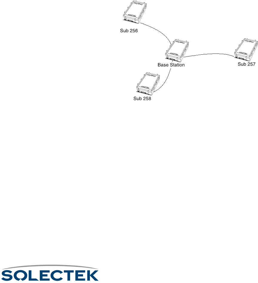
Understanding RF-DLC
65
Understanding RF-DLC
The following is a discussion of the RF-DLC protocol, which provides you with back-
ground information before you begin configuration.
The RF-DLC Protocol
RF-DLC is a proprietary protocol based on the HDLC protocol. It is a polling protocol
for star-based networks with a base station and one or more substations, and partici-
pates in transmitting frames from one station to another. The base station controls
communications with each sub station and maintains the RF link. The base station com-
municates with one sub station at a time. The sub stations communicate only with the
base station and not with each other.
In the following diagram showing a point-to-multipoint configuration, the base station
communicates with the sub stations in a star topology.
In a point-to-point configuration, there is one base station and one sub station.
Automatic Discovery Protocol
When a sub station begins operation, it can receive packets but may not be able to fully
communicate with the base station until the base station is configured to recognize it.
RF-DLC uses another protocol called Automatic Discovery Protocol (ADP) to learn
about a sub station and begin communicating with it. Once the base station assigns a
sub-station number to the sub station, the base station then uses the RF-DLC protocol
to continue communications.
Enabling ADP
The base station is enabled for ADP on the RF-DLC base port by default. With ADP
enabled, the base station can use ADP to identify and set up an unassigned sub station.
The discovery process is outlined below.
With ADP enabled, you must choose the ADP mode, which specifies how the sub sta-
tion handles broadcasts: either Auto Acceptance or Manual Acceptance.
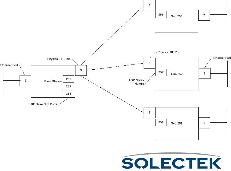
66
•Using Auto Acceptance, the base station automatically accepts the sub station.
•Using Manual Acceptance, you must manually accept each sub station by
enabling the Accept Status field (in “1.2.3.1.4 ADP Substation Configuration” on
page 81) for that Sub Station Number.
Disabling ADP
When configuring the base station, you may choose to disable ADP, which can result in
reduced overhead. If you disable ADP, you must manually assign the base sub ports for
the sub stations by using 1.2.3.1.3 RF Base Sub Port Configuration, described in detail on
page 80. to enter the Sub-Station Number and IP address information. On the sub station,
you must also manually set up the RF sub ports, entering in the same Sub-Station Number
in “1.2.3.1.2 RF Sub Port Configuration” on page 78.
If ADP is disabled, the ADP polling operation does not apply (see “ADP Discovery Pro-
cess” on this page).
ADP Discovery Process
The discovery process is as follows when ADP is enabled:
• The base station is not yet aware of the sub station, and the sub station is waiting
for an ADP request from the base. The base station sends out a broadcast
request at the broadcast address of 255.
• The sub station replies to the broadcast with its IP address.
• The base station sends another broadcast to assign the station address (Sub-sta-
tion Number). The base station assigns the next available address to the sub sta-
tion. This is the base sub port address for the sub station in the range of 256 to
512.
• The base station can now communicate with the sub station using RF-DLC
frames:

Understanding RF-DLC
67
RF-DLC Frame Types
RF-DLC frames contain an address field which defines the sub station address, broad-
cast address, or group address. RF-DLC frames also contain a control field containing
commands, responses, and counts used to maintain the link. The control field formats
are:
• Unnumbered - used to initialize the sub station and send information using an
unreliable mechanism.
• Supervisory - used to acknowledge the receipt of information frames, convey
ready or busy conditions, and report frame numbering errors.
• Information Transfer - used to transfer data using a reliable mechanism. Infor-
mation frames are numbered, meaning the control field contains Ns counts,
which ensure frames are received in their proper order, and Nr counts, which
confirm that information frames were received and accepted.
The RF-DLC frame also contains a CRC bit for error checking.
RF-DLC Commands and Responses
The base station sends a command to the sub station, which sends back a response.
Commands and Responses are of Unnumbered, Supervisory, or Information format.
Note The 2.5.1 Base Port Status screen provides the status of frame activity. For descriptions
of RF-DLC commands and responses, see 2.5.1 RF-DLC Base Port Status, described
in detail on page 140, and 2.5.2 RF-DLC Sub Port Status, described in detail on
page 143.
Polling
The base station polls the substations one at a time to see if they have packets to send
to the base station.The base station manages three poll lists to which it assigns devices,
based on their activity:
•Substations on
the Fast Poll
Fast PollFast Poll
Fast Poll list are constantly being polled one at a time in
order by the base. The polling frequency is contingent upon the number of
substations.
• A substation drops to Slow Poll
Slow PollSlow Poll
Slow Poll if it does not respond to the base station in 4
times with no response. A sub can also drop to Slow Poll if it responds with “n”
RRs and there is no data in either direction.
• A substation drops to Inactive Poll
Inactive PollInactive Poll
Inactive Poll if either of the following events occurs:
•While being on Slow Poll, the sub does not respond to the base in 8 tries.
•It is the only sub station to respond to the base with RR responses and no
data in either direction.
Consider a base station with three sub stations on the fast poll list, two substations on
the slow poll list, and one on the inactive poll list. The slow poll timer is set to one

68
minute and the inactive timer is set to five minutes. The slow poll timer’s value is
always less then that of the inactive timer.
The base station polls the fast poll sub stations until one minute has passed. Then it
polls the sub stations on the slow poll list, then moves back to poll the fast poll sub sta-
tions, and continues in this fashion until five minutes has passed. The base station then
polls the inactive sub station and always broadcasts an ADP packet, if ADP is enabled.
Error Detection and Recovery
I-frames (data frames) can contain several Bridged-Ethernet frames or routed IP data-
grams. They are sequence numbered: Ns is the frame number, Nr is an ACK, meaning
all frames 'r' were received.
If the base station gets an I-frame out of sequence, it assumes one was missed and
sends out a reject packet. Errors are handled as follows:
• If Ns gets ahead by one, the packet is rejected. The other side retransmits.
• If Nr changes and a frame is acknowledged but was not sent out, the base
sends back a disconnect to the sub station, or the sub station sends a FRMR
(Frame reject response) to the base station. This is a logical disconnect, the RF
physical link is maintained.
• The sub station resets and the base makes an attempt to re-establishes the RF-
DLC session on the next polling cycle.

Configuring the Ports
69
Configuring the Ports
How you configure the SkyWay Bridge/Router depends on your network topology.
Configure each unit separately depending on its role as a base station or sub station,
and its function as a bridge, router, or both bridge and router.
Note Serial Port configuration is discussed in Chapter 2 (see “1.2.1.1 Serial Port Configura-
tion” on page 24).
Before you Begin
The following helps you determine how to configure the unit:
1. Decide if the unit will be a base station or a sub station.
2. Decide if the unit will perform bridging, routing, or both bridging and routing. The
default configuration is bridging enabled, routing disabled.
3. If you are configuring the unit for routing, have the IP configuration data ready (IP
address, IP Mask, etc.).
When you make changes to the screens and type .W, you update the configuration
database. However, for some changes, such as configuring the RF ports, you must
cycle the port to start the new configuration. This is described in “Configuring the Sky-
Way as a Base Station” on page 69.
Obtaining IP Addresses
IP network addresses are unique numbers assigned by the Internet Assigned Numbers
Authority (IANA) (see RFC 2050). See your system manager to obtain IP addresses. If
your network is not connected to the Internet directly or indirectly, see RFC 1918,
which defines class C addresses in the range of 192.168.0.0 - 192.168.255.0 that you
may use.
Setting up IP Addresses
Each unit, whether a base station or a sub station, must have a unique IP address for
the RF port, even if you are enabling bridging only. The system derives the RF MAC
address from the RF IP address. If you are enabling routing, you also need to set up the
IP address for the Ethernet port (for more information, see “1.4.2 IP Port Configura-
tion” on page 95).
Configuring the SkyWay as a Base Station
1. Set up a unique IP address for the RF Port.
a. Go to screen 1.4.2 IP Port Configuration, described in detail on page 95.
b. For Port # 3 (the RF port), enter the IP Address and the IP Mask.
c. Press .W to update the database.

70
2. Configure the RF Transceiver settings: RF Frequency, RF Data Rate, and Scrambler
Ta p Va lu e s .
a. Go to screen 1.2.3.3 RF Transceiver Configuration, described in detail on
page 72.
b. Set the RF Frequency, RF Data Rate, and Scrambler Tap values.
c. Press .W to update the database.
3. Invalidate the RF Diagnostics Port configuration. As shipped, the default RF port is
the RF-DLC Sub Diagnostics Port. You must invalidate it before setting the RF port
up as a base port.
a. Go to 1.2.3.2 RF Diagnostic Port Configuration, described in detail on
page 73. The port number is 3, and the port type is Sub Diag, which is the
default.
b. Set the Record Type field to Invalid.
c. Press .W to remove this configuration record from the database.
4. Configure the RF port as a base port.
a. Go to 1.2.3.1.1 RF Base Port Configuration, described in detail on
page 74.
b. Press .A. This automatically adds port 3 as a base port. The fields now
contain the default settings.
5. Accept the defaults or change the base port configuration settings:
• Configuration Status - You might want to set this Off-line to complete configur-
ing all your units, then change the configuration status of all units to On-line
before rebooting (see step 5).
• Max Buffers - these are the message buffers for the system.
• Transmit and Receive Buffers - these are shared between the serial and RF
ports. There are 512 total.
• Maximum Frame Size - The physical MTU (not configurable).
• Slow Polling Timeout - number of seconds that elapse before the base station
checks the sub stations on the slow poll list.
• First Sub Station Number - logical address of the first sub station (default is
256).
• Last Sub Station Number - logical address of the last sub station in the topol-
ogy.
• Automatic Discovery Protocol - if enabled, the base station uses ADP to send
broadcasts to the sub stations. You must also configure the ADP mode. If dis-
abled, ADP mode does not apply, there fore you must manually configure the
base station for the base sub ports (see “Configuring the Base Sub Ports” on
page 80).

Configuring the Ports
71
• ADP mode - applies only if Automatic Discovery Protocol is enabled. Auto
Acceptance is the default. If you set ADP mode to Manual Acceptance, you
must configure the base station to manually accept the sub stations.
• ADP Timeout Interval - applies only if Automatic Discovery Protocol is
enabled.
When finished setting the base port configuration, type .W to update the database.
6. Initialize the RF port. At this point, you have made the changes to the database, but
before the changes take affect, you must initialize the port. There are two ways to
do this:
• Cycle the port:
a. Go to 2.2.1 Generic Port Status and Control.
b. Type 3 (or .N until the port number is 3).
c. Set the Administrative Status field to Cycle.
d. Type .W
Cycle evacuates the port, eliminates the driver, reads the database, reinstalls the driver,
and brings up the port.
• Reset the unit:
a. Go to the Main Menu
b. Type 5 (Start Application).
c. Choose Run Time as the Application to Start.
This reloads the updated database containing the new configuration parame-
ters.
You can configure only one base station, but you can configure as many as 64 sub
stations.

72
1.2.3.3 RF Transceiver Configuration
Use this screen to set RF Frequency, RF Data Rate, and Scrambler Tap values.
Field Name MIB Settings (default in
bold)
RF Port [swRFTransCfgIndex] 3
The RF port number is 3.
RF Frequency [swRFTransCfgFre-
quency]
2468 Mhz
The transmitted and received frequency for this SkyWay. This setting must match all
other stations communicating with this SkyWay.
RF Data Rate [swRFTransCfgDataRate] • 2 Mbps
• 5.5 Mbps
• 11 Mbps
This setting must match all other stations communicating with this SkyWay.
Scrambler Tap [swRFTransCfgScramb-
lerTap]
72
Determines how the SkyWay scrambles data between two units. This setting must
match all other stations communicating with this SkyWay.
1.2.3.3. RF Transceiver Configuration Record 1 of 1
RF Port RF Frequency RF Data Rate Scrambler Tap
------- ------------ ----------- ------------
3 2468 Mhz 2 Mbps 72
\ - return to menu . - commands TAB - next available field ENTER - edit

Configuring the Ports
73
RF Diagnostics Port
There are two diagnostic ports, the RF-DLC Base Diagnostic port and the RF-DLC
Sub Diagnostic port. Both of these use the control interface of the RF driver to perform
RF diagnostics.
1.2.3.2 RF Diagnostic Port Configuration
The following table lists the field name, the MIB name, and field options with the
default setting in bold:
Field Name MIB Settings (default in
bold)
Port Number [swRFDiagPortIndex] 3
The RF port number.
Configuration Status [swRFDiagPortConfigSta-
tus]
• On-line
• Off-line
Determines if this port is initialized upon reset. Off-line prevents the port from being
initialized upon reset.
Port Type [swRFDiagPortPorttype] RF Sub Diagnostics Port
RF Sub Diagnostic port.
Max Buffers [swRFDiagPortMax-
Buffers]
800
The number of message buffers.
Transmit Buffers [swRFDiagPortTransDesc] 240
The number of transmit buffers.
1.2.3.2 RF Diagnostic Port Configuration Record 1 of 3
Port Number :3
Configuration Status :On-line
Port Type :RF-DLC SUB Diagnostic Port
Max Buffers :800
Transmit Buffers :240
Receive Buffers :180
Maximum Frame Size :1549
Record Type :Valid
\ - return to menu . - commands TAB - next available field ENTER - edit

74
1.2.3.1.1 RF Base Port Configuration
The following table lists the field name, MIB, and settings with the default setting in
bold. If only one setting is shown, it is the default:
Receive Buffers [swRFDiagPortRecvDesc] 180
The number of receive buffers.
Maximum Frame Size [swRFDiagPortmax-
FrameSize]
3200
The physical MTU, or largest frame that can be transmitted. This field is not config-
urable.
Record Type [swRFDiagPort] • Valid
• Invalid
The status of this configuration.
Field Name MIB Settings (default in
bold)
Port Number [swRFBasePortIndex] 3
The RF port number.
Field Name MIB Settings (default in
bold)
1.2.3.1.1 RF Base Port Configuration Record 1 of 1
Port Number : 3
Configuration Status : Off-line
Port Type : RF-DLC Base Port
Max Buffers : 800
Transmit Buffers : 240
Receive Buffers : 180
Maximum Frame Size : 3200
Slow Polling Timeout-seconds : 15
First Sub Station Number : 256
Last Sub Station Number : 287
Automatic Discovery Protocol : Enabled
ADP Mode : Auto Acceptance
ADP Timeout Interval-seconds : 60
Record Type : Valid
\ - return to menu . - commands TAB - next available field ENTER - edit

Configuring the Ports
75
Configuration Status [swRFBasePortConfigSta-
tus
•
••
• Off-line
Off-lineOff-line
Off-line
• On-line
Determines if the port is initialized upon reset. Off-line prevents the port from initial-
izing upon reset.
Port Type [swRFBasePortPortType] RF-DLC Base Port
This is a read-only field that defines this port as a base port.
Max Buffers [swRFBasePortMax-
Buffers]
800
The number of message buffers allocated to this base port.
Transmit Buffers [swRFBasePortTrans-
Desc]
240
The number of transmit buffers.
Receive Buffers [swRFBasePortRecvDesc] 180
The number of receive buffers.
Maximum Frame Size [swRFBasePortMax-
FrameSize]
3200
This is a read-only field that sets the physical MTU, or largest frame that can be
transmitted from this port.
Slow Polling Timeout [swRFBasePortSlow-
PollTO]
15 seconds
The slow poll time out interval in seconds.
First Sub Station Number [swRFBasePortFirstSub-
Addr]
256
The first possible sub station number.
Last Sub Station Number [swRFBasePortLastSub-
Addr]
287
The last possible sub station number.
Automatic Discovery Pro-
tocol
[swRFBasePortADP] •
••
•Enabled
EnabledEnabled
Enabled
• Disabled
Determines if Automatic Discovery Protocol is running. If enabled, you must also
specify the ADP mode.
Field Name MIB Settings (default in
bold)

76
ADP Mode [swRFBasePortADP-
Mode]
Auto Acceptance
Applies only if ADP is enabled. Auto Acceptance means the base station automati-
cally accepts sub stations. Manual Acceptance means you must manually accept the
sub stations (see “1.2.3.1.4 ADP Substation Configuration” on page 81).
ADP Timeout Interval -
seconds
[swRFBasePortADPTO] 60
Applies only if ADP is enabled. Determines how often (in seconds) the base stations
sends an ADP broadcast.
Record Type: [swRFBasePortType] • Invalid
• Valid
Indicates the status of this base port configuration. If valid, this base port configura-
tion is enabled. If invalid, this port is removed as a base port after the next reset.
Field Name MIB Settings (default in
bold)

Configuring the Ports
77
Configuring the SkyWay as a Sub Station
Configure the sub station in much the same way as you set up the base station. Config-
uration is simpler, however, because you do not have as many configuration parame-
ters to set up.
1. Configure the RF Transceiver settings: RF Frequency, RF Data Rate, and Scrambler
Tap Values. Make sure these settings correspond to the base station settings for
these fields.
a. Go to screen 1.2.3.3 RF Transceiver Configuration, described in detail on
page 72.
b. Set the RF Frequency, RF Data Rate, and Scrambler Tap values.
c. Press .W to update the database.
2. Invalidate the RF Diagnostics Sub Port. As shipped, the default RF port is set to the
RF diagnostics sub port. You must invalidate it before setting the RF port up as a
base port.
a. Go to 1.2.3.2 RF Diagnostic Port Configuration, described in detail on
page 73. The port number is 3, and the default port type is Sub Diag.
b. Set the Record Type field to Invalid to remove this configuration record
from the database.
c. Type .W to update the database.
3. Configure the RF port as a sub port.
a. Go to “1.2.3.1.2 RF Sub Port Configuration” on page 78.
b. Press .A. This automatically adds port 3 as a sub port and allows you to
begin editing the screen.
c. Leave Max Buffers, Transmit and Receive Buffers at the default settings.
d. Set the Sub-Station Number. This is the base sub port address; for exam-
ple, 256. If ADP is enabled, you do not need to enter a sub-station num-
ber. If ADP is disabled, you must enter a station number. It is the next
available RF Base Sub Port number determined during network setup.
e. Set RF data rate to the same value as the base station.
f. Set Link Down Timeout Interval (only if ADP is enabled). This timer speci-
fies the amount of time in milliseconds the sub station can be inactive
before going into ADP mode.
g. Type .W to update the database.
4. Set up a unique IP address for the RF Port.
a. Go to screen 1.4.2 IP Port Configuration, described in detail on page 95.
b. For Port # 3 (the RF port), enter the IP Address and the IP Mask.
c. Type .W to update the database.
5. Reset or cycle the port as described in step 5 of “Configuring the SkyWay as a Base
Station” on page 69.

78
1.2.3.1.2 RF Sub Port Configuration
Note Ty p e .A to begin editing the screen.
Use this screen to set the sub station port parameters. The following table lists the field
name, MIB, and the default, or field options with the default in bold:
1.2.3.1.2 RF Sub Port Configuration Record 0 of 0
Port Number :3
Configuration Status :On-line
Port Type :RF-DLC Sub Port
Max Buffers :800
Transmit Buffers :240
Receive Buffers :180
Maximum Frame Size :3200
Sub Station Number :0
Link down Timeout Interval (1.5 msec) :320
Record Type :Valid
\ - return to menu . - commands TAB - next available field ENTER - edit
Field Name MIB Settings (default in
bold)
Port Number: [swRFSubPortIndex] 3
The RF physical port number is 3.
Configuration Status: [swRFSubPortConfigSta-
tus]
•
••
• On-line
On-lineOn-line
On-line
• Off-line
Determines if the port is initialized when a reset occurs. Set Off-line to prevent the
port from initializing upon reset. Online initializes the port upon reset.
Port Type [swRFSubPortPortType] Sub Port
This read-only field defines this port as a sub station port.
Max Buffers: [swRFSubPortMaxBuffers] 800
The number of message buffers allocated to this sub station port.
Transmit Buffers: [swRFSubPortTransDesc] 338
The number of transmit buffers.
Receive Buffers: [swRFSubPortRecvDesc] 140

Configuring the Ports
79
The number of receive buffers.
Maximum Frame Size: [swRFSubPortMaxFrame-
Size]
3200
This read-only field sets the maximum frame size for each frame originating from
this port.
Sub Station Number [swRFSubPortStation-
Num]
0
Sub Station number for this sub station. If ADP is enabled, set this parameter to
zero.
Link Down Timeout
Interval
[swRFSubPortLinkTO] Seconds
The length of time this substation tries to link up to the base station.
Record Type [swRFSubPortType] • Valid
• Invalid
Indicates the status of this port configuration. If valid, this port configuration is
enabled. If marked as invalid, after the next reset or port cycle, this port will not exist
as a sub station port.
Field Name MIB Settings (default in
bold)

80
Configuring the Base Sub Ports
If you have disabled ADP, you must manually configure the base sub ports on the base
station using the 1.2.3.1.3 RF Base Sub Port Configuration screen. If you have ADP
enabled, you do not need to configure base sub ports.
1.2.3.1.3 RF Base Sub Port Configuration
Note Ty p e .A to add a base sub port and to begin editing.
The following table lists the field name, MIB, and the default or field options with the
default setting in bold:
1.2.3.1.3 RF Base Sub Port Configuration Record 1 of 1
Sub Station Number :256
Configuration Status :On-line
Port Type :RF-DLC Base to Sub Port
Corresponding Substation RF Port
IP Address :000.000.000.000
Record Type :Valid
\ - return to menu . - commands TAB - next available field ENTER - edit
Field Name MIB Settings (default in
bold)
Sub Station Number [swRFBaseSubPortIndex] 256
The sub station number for this Base to Sub station port.
Configuration Status [swRFBaseSubPortCon-
figStatus]
•
••
• On-line
On-lineOn-line
On-line
• Off-line
Determines if the port is enabled during initialization (On-line). Set to off-line to dis-
able the port.
Port Type [swRFBaseSubPortPort-
Ty p e ]
RF-DLC Base to Sub Port
This read-only field defines this port as a RF-DLC Base to Sub station port.
Corresponding Substation
RF Port IP Address
[swRFBaseSubPortSub-
RFIPAddr]
000.000.000.000
The IP address of the sub station.

Configuring the Ports
81
Validating Accept Status of a Sub Station
This section applies only if you set ADP mode to Manual Acceptance. Use screen
1.2.3.1.4 ADP Substation Configuration to validate the accept status for each sub sta-
tion listed. The screen only shows sub stations that have not yet been accepted by the
base station. Once they are accepted, they appear in screen 2.5.2 RF-DLC Sub Port
Status, described in detail on page 143.
1.2.3.1.4 ADP Substation Configuration
Record Type [swRFBaseSubPortType] •
••
• Valid
ValidValid
Valid
• Invalid
Indicates the status of this RF Sub station port configuration. If valid, this port config-
uration is enabled. If marked as invalid, this record will be deleted after the next
reset.
Field Name MIB Settings (default in
bold)
Sub Station Number [swADPStationIndex]
The base sub port number of the sub station.
Field Name MIB Settings (default in
bold)
1.2.3.1.4 ADP Substation Configuration Record 1 of 1
Sub Station IP Accept
Number Address Status
--------- --------- -------
256 196.028.145.069 No
\ - return to menu . - commands TAB - next available field ENTER - edit

82
IP Address [swADPStationNetAd-
dress]
The IP address of the sub station.
Accept Status [swADPStationStatus] • Yes
•
••
•No
NoNo
No
Enter Yes to enable acceptance.
Field Name MIB Settings (default in
bold)

Configuring the Ports
83
Configuring the Ethernet Port
1.2.2.1 Ethernet Port Configuration
Field Name MIB Settings (default in
bold)
Port Number [swEtherPortIndex] 2
The Ethernet port is 2.
Configuration Status [swEtherPortConfigSta-
tus]
• On-line
• Off-line
Determines whether the port comes up at initialization time. You must reset the unit
for changes to take affect.
MAC Address [swEtherPortPhysAd-
dress]
The MAC address of this Ethernet port.
Bridging Encap Type [swEtherPortBridgingEn-
capType]
• Ethernet II encap
• Ethernet 802.3 encap
Encapsulation used for bridging.
Port Type [swEtherPortPortType] Ethernet 802.3
This field is not configurable.
1.2.2.1. Ethernet Port Configuration Record 1 of 1
Port Number : 2
Configuration Status : On-line
MAC Address : 00:ba:d0:ba:be:00
Bridging Encap Type : Ethernet 802.3 encap
Port Type : Ethernet 802.3
Buffers : 1200
Transmit Buffers : 256
Receive Buffers : 512
Maximum Frame Size : 1518
Record Type : Valid
\ - return to menu . – commands TAB - next available field ENTER - edit

84
Buffers [swEtherPortMaxBuffers] 780
The number of message buffers allocated to this Ethernet port.
Transmit Buffers [swEtherPortTransDesc] 256
The number of transmit buffers.
Receive Buffers [swEtherPortRecvDesc] 256
The number of receive buffers.
Maximum Frame Size [swEtherPortMaxFrame-
Size]
1518
The physical MTU.
Record Type [swEtherPortType] • Valid
• Invalid
If valid, this configuration is enabled upon reset. If invalid, this configuration record is
deleted at the next reset.
Field Name MIB Settings (default in
bold)

Configuring the Ports
85
Configuring the Ethernet Transceiver
1.2.2.2 Ethernet Transceiver Configuration
Field Name MIB Settings (default in
bold)
Ethernet Port Number [swEtherTransCfgIndex] 2
The Ethernet port number is 2.
Interface Type [swEtherTransCfgInter-
face]
•
••
•Auto-Negotiation
Auto-NegotiationAuto-Negotiation
Auto-Negotiation
• 10BASE-T
• 100BASE-TX
• 100BASE-FX
Type of interface connected to the Ethernet port.
Duplex Mode [swEtherTransCfgDuplex] •
••
• Full Duplex
Full DuplexFull Duplex
Full Duplex
•Half Duplex
Duplex Mode for the Ethernet transceiver.
SQE (10Base-T) [swEtherTransCfgSQE] •Enabled
•
••
• Disabled
DisabledDisabled
Disabled
When SQE (heartbeat) function is enabled, the transceiver will assert COL output
for 5-15 BT after each packet. Valid only for 10Base-T.
1.2.2.2. Ethernet Transceiver Configuration Record 1 of 1
Ethernet Port Number : 2
Interface Type : Auto-Negotiation
Duplex Mode : Full Duplex
SQE (10Base-T) : Disabled
Jabber (10Base-T) : Enabled
Auto Negotiate : Enabled
Remote Fault : Disabled
Pause : Enabled
100BASE-TX full-duplex : Enabled
100BASE-TX : Enabled
10BASE-T full-duplex : Enabled
10BASE-T : Enabled
Selector Field : IEEE 802.3
Record type : Valid
\ - return to menu . - commands TAB - next available field ENTER -
e

86
Jabber (10Base-T) [swEtherTransCfgJabber] • Enabled
EnabledEnabled
Enabled
• Disabled
Disables transmit and loopback on the Ethernet transceiver if the MA transmission
exceeds the jabber timer. Valid only for 10Base-T.
Auto Negotiate [swEtherTransCfgAuto-
Negotiation]
•
••
•Enabled
EnabledEnabled
Enabled
• Disabled
Status field indicating if Auto-negotiation for the Ethernet port is enabled as deter-
mined by the Interface Type setting.
Remote Fault: [swEtherTransCfgRe-
moteFault]
•Enabled
•
••
• Disabled
DisabledDisabled
Disabled
Modifiable only is Auto-negotiation is enabled. Enables/disables remote fault report-
ing.
Pause: [swEtherTransCfPause] •
••
•Enabled
EnabledEnabled
Enabled
• Disabled
Modifiable only is Auto-negotiation is enabled. Enables pause operation for full
duplex link or disables pause operation.
100BASE-TX full-duplex: [swEtherTransCfg100Bas
eTXFullDuplex]
•
••
•Enabled
EnabledEnabled
Enabled
• Disabled
Modifiable only is Auto-negotiation is enabled. Enables 100Base-TX full duplex for
DTE capability.
100BASE-TX: [swEtherTransCfg100Bas
eTX]
•
••
•Enabled
EnabledEnabled
Enabled
• Disabled
Modifiable only is Auto-negotiation is enabled. Enables 100Base-TX f for DTE capa-
blility.
10BASE-T full-duplex: [swEtherTransCfg10Base
TFullDuplex]
•
••
•Enabled
EnabledEnabled
Enabled
• Disabled
Modifiable only is Auto-negotiation is enabled. Enables 10Base-T full duplex for DTE
capability.
10BASE-T: [swEtherTransCfg10Base
T]
•
••
•Enabled
EnabledEnabled
Enabled
• Disabled
Modifiable only is Auto-negotiation is enabled. Enables 10Base-T for DTE capability.
Field Name MIB Settings (default in
bold)

Configuring the Ports
87
Selector Field: [swEtherTransCfgSelec-
tor]
•
••
• IEEE 802.3
IEEE 802.3IEEE 802.3
IEEE 802.3
• IEEE 902.9 ISLAN 16T
Modifiable only is Auto-negotiation is enabled. This is the IEEE Selector Field. Typical
users can accept the default of IEEE 802.3.
Record Type: [swEtherTransCfgType] •
••
• Valid
ValidValid
Valid
• Invalid
Indicates the status of this particular ethernet transceiver configuration. If valid, this
configuration is enabled. If marked as invalid, this record will be deleted and will not
exist after the next reset.
Field Name MIB Settings (default in
bold)

88
Bridging
The SkyWay Bridge/Router can function as either a bridge or a router or both. When a
packet arrives at the bridge, SkyWay examines it and determines its protocol type. The
packet is then forwarded or discarded, depending on the functions enabled on the
bridge:
• Bridging only - All packets are forwarded without regard to protocol
• Routing only - Only IP suite packets are forwarded; all other protocols are dis-
carded
• Bridging and routing - IP suite packets are routed; all other protocols are
bridged
However, if IP packets are sent to the bridge itself (its own IP address), it will accept
them even if it is configured for bridging only.
Enabling and Disabling Bridging
Bridging is a global parameter, and the SkyWay Bridge/Router is configured by default
with bridging. Disable bridging in “1.3.1 Bridge Configuration” on page 90. In this
screen you also set the global bridge parameters when bridging is enabled. Then set
up the ports for bridging operation in “1.3.2 Bridge Port Configuration” on page 92.
If you enable bridging, the bridge receives the frame and determines what action
should be taken, that is, to forward or “filter” (drop the packet), based on the state of
the bridge ports.
Port States
Each bridge port has a state associated with it. The port state is set by management or
dynamically by other means (such as the Spanning Tree algorithm). There are five port
states:
Port State Description
Blocking The port does not forward frames,
but is included in the Spanning Tree
topology.
Listening The port is ready to forward frames,
and Learning is disabled.
Learning The port is ready to forward frames,
and Learning is enabled. The port is
still not forwarding.
Forwarding The port is forwarding frames.
Disabled The port does not forward frames,
and is not included in the Spanning
Tree topology.

Bridging
89
As shown in the above table, the state determines if the bridge will allow the port to
transmit frames. If you disable the port, it is excluded from bridge operation altogether.
However, a port that is not disabled can be dynamically excluded by the Spanning Tree
algorithm (see “Spanning Tree” on page 89).
Topology Support.
Topology Support.Topology Support.
Topology Support. The bridge supports the topology by determining which ports are
‘eligible’ to transmit frames. The bridge enables each port and allows it to transmit
frames if all of the following conditions apply:
• The port that received the frame was in a forwarding state.
• The port eligible for transmission is in a forwarding state.
• The port eligible for transmission is not the same as the port the packet was
received on.
• The size of the MTU conveyed by the frame does not exceed the maximum
size of MTU supported by the LAN to which the port eligible for transmission
is attached.
The frame is discarded if the port does not meet the above conditions.
Spanning Tree
Spanning Tree allows the bridge to determine which ports to shut down (put in Block-
ing mode) to break any loops which may occur in the topology. It uses an algorithm
that figures out the best route and determines which ports will be included in the Span-
ning Tree. If the Spanning Tree algorithm sets the port state to Blocking, the port will
not allow duplicate frames which result from multiple paths (loops) in the active topol-
ogy of the bridge to be transmitted. If you disable bridging, you also disable Spanning
Tree, as it applies to the bridging function only. You can then set the ports manually if
Spanning Tree is disabled but bridging is enabled in 1.3.2 Bridge Port Configuration,
described in detail on page 92.

90
1.3.1 Bridge Configuration
Use this screen to set global bridging parameters, disable bridging, or enable the Span-
ning Tree function.
Note The SkyWay does not support Port Priority [dotIdStpPortPriority] as defined in
RFC1493.
The following table lists the field name, the MIB name, and the default setting:
1.3.1. Bridge Configuration
Bridging : Enabled
Forwarding Table Timeout : 300
Spanning Tree : Enabled
Bridge Priority : 16961
Bridge Max Age : 20
Bridge Hello Timeout : 2
Bridge Forward Delay : 15
Multicast Address : 01:80:c2:00:00:00
\ -return to menu . - commands TAB - next available field ENTER - edit
Field Name MIB Settings (default in
bold)
Bridging [swBridgeEnable] •
••
•Enabled
EnabledEnabled
Enabled
• Disabled
Enables or disables bridging on the system. If you disable bridging on this screen, it is
disabled for all ports. If you change this parameter, you must reset the unit. Bridging
supersedes spanning tree function, that is, if you disable bridging, spanning tree is
also disabled.
Fowarding Table Timeout [dotldTpAgingTime] 300
The timeout period in seconds for aging out dynamically learned forwarding infor-
mation.
Spanning Tree [swBridgeSTPEnable] • Enabled
•
••
• Disabled
DisabledDisabled
Disabled
Enables or disables spanning tree function.

Bridging
91
Bridge Priority [dotIdStpPriority] 32768
This allows you to influence the choice of root bridge and designated bridge. A
lower numerical value means the bridge is closer to becoming the root. and thereby
change the topology of the spanning tree.
Bridge Max Age [dotIdStpBridgeMaxAge] 20
The amount of time in seconds the bridge waits before it discards configuration
BPDUs.
Bridge Hello Timeout [dotIdStpBridgeHello-
Time]
2
The amount of time in seconds before the bridge issues a configuration BPDU.
BPDU Forward Delay [dotIdStpBridgeForward-
Delay]
15
The amount of time a port waits before going into a forwarding state.
Multicast Address [swBridgeMulticastAddr]
The spanning tree multicast address contained in the configuration BPDU (mes-
sage). This is the MAC address of packets intended for a bridge.
Field Name MIB Settings (default in
bold)

92
1.3.2 Bridge Port Configuration
Use this screen to configure the port for bridging.The following table lists the field
name, the MIB name, and the default setting:
Field Name MIB Settings (default in
bold)
Port Number [swBridgePortIndex]
This is the port number used as a bridging port.
Bridging State [swBridgePortBridging-
State]
•Enabled
• Disabled
Specify if bridging is enabled or disabled for this port. This controls the port’s bridg-
ing operation if Spanning Tree is disabled.
STP State [swBridgePortSTPState] • Disabled
• Blocking
•Listening
•Learning
•Forwarding
This is a status field which tells you the current state for this port. For example, in the
screen above, both ports are in the Forwarding state.
STP Port Cost [swBridgePortSTPCost]
Determines the cost of the path to the root through this port.
1.3.2. Bridge Port Configuration Record 1 of 1
Port Bridging STP STP Port
Number State State Cost
------ -------- -------- --------
2 Enabled Forwarding 10
256 Enabled Forwarding 100
\ - return to menu . - commands TAB - next available field ENTER - edit

IP Routing
93
IP Routing
IP routing is a global parameter. It is disabled by default, but you can enable the unit for
IP routing only or in addition to bridging. You cannot configure routing on a port to
port basis.
Configuring IP
Use the 1.4.1 IP Protocol Configuration screen to enable IP routing and set global
routing parameters.
1.4.1 IP Protocol Configuration
The following table lists the field name, the MIB name, and the default setting:
Field Name MIB Settings (default in
bold)
Routing [ipForwarding] Disabled
Enables or disables IP routing on this unit.
Time to Live [ipDefaultTTL] 64
Specified the number of hops a packet can be forwarded before it is discarded.
ICMP Redirect Route
Clearing Interval
[swIpIcmpredirectdlear-
ingInterval]
1800
The interval of time, in seconds, in which routes learned from ICMP redirect mes-
sages are cleared.
1.4.1. IP Protocol Configuration
Routing : Disabled
Time To Live : 64
ICMP Redirect Route Clearing Interval : 1800
Forward Broadcasts : Enabled
IP Reassembly Timeout : 8
Default Gateway:
Default Gateway Enabled : No
Default Gateway Ip Address : 000.000.000.000
Default Gateway Port Number : 3

94
Forward Broadcasts [swIpBcastforwarding] •Enabled
• Disabled
Indicates whether IP broadcast messages are forwarded (Enabled) or not forwarded
(Disabled) if they are received.
IP Reassembly Timeout [swIpReasTimeout] 8
Determines how many seconds to wait before discarding a packet when all frag-
ments have not yet arrived.
Default Gateway Enabled [swDefaultGateway] •
••
•No
NoNo
No
•Yes
Set to Yes to set a default gateway.
Default Gateway IP
Address
[swDefaultGatewayI-
PAddr]
Enter the IP address to send IP datagrams for which no route was found
Default Gateway Port
Number
[swDefaultGatewayInter-
face]
The SkyWay port number to use when forwarding IP datagrams with unknown
routes.
Field Name MIB Settings (default in
bold)

IP Routing
95
Configuring the IP Ports
Before you begin you need to have the IP Address and the IP Mask for the unit you are
configuring.
1.4.2 IP Port Configuration
The following table lists the field name, the MIB name, and the default setting:
Field Name MIB Settings (default in
bold)
Port Number [swIpPortIndex] 2
The port number for this IP configuration.
Proxy ARP [swIpPortProxyArp] •Enabled
• Disabled
Determines whether proxy Address Resolution Protocol (ARP) is enabled.
IP Address [swIpPortAddr]
This is the IP address for this IP port (configurable).
IP Mask [swIpPortMask]
This is the subnet mask.
1.4.2. IP Port Configuration Record 1 of 2
Port Number : 2
Proxy ARP : Enabled
IP Address : 134.196.034.001
IP Mask : 255.255.000.000
IP Encapsulation : Standard Ethernet
IP MTU : 1492
Arp Retry Timeout : 30
Arp Aging Timeout : 300
Arp Max Retries : 5
Configuration Status : Valid
\ - return to menu . - commands TAB - next available field ENTER - edit

96
IP Encapsulation [swIpPortEncap] •
••
•Standard Ethernet
Standard EthernetStandard Ethernet
Standard Ethernet
•DOD Ethernet
• SNAP 802.3
• DOD 802.3
This defines the IP encapsulation type for this network.
IP MTU [swIpPortMTU] 1492
This sets the maximum transfer unit size.
Arp Retry Timeout [swIpPortArpRetryTO] 10
The amount of time in seconds to wait for an ARP reply before sending the next
ARP request.
Arp Aging Timeout [swIpPortArpAgingTO] 300
The amount of time in seconds to hold an entry in the ARP table before removing it.
Arp Max Retries [swIpPortArpMaxRetries] 5
The number of times an ARP request is repeated without receiving an ARP reply.
The minimum value is 1, the maximum value is 15 and the default should be 5.
Configuration Status [swIpPortType] • Valid
• Invalid
Set to Invalid to delete an entry in the IP ports table.
Field Name MIB Settings (default in
bold)

IP Routing
97
Setting up Static Routing
Set up IP static routes in 1.4.3 IP Static Routes Configuration, described in detail on
page 97.
Note For more information about IP Static Routes, see Static Routing is the Best Choice for
Service Providers, a white paper published by Solectek.
1.4.3 IP Static Routes Configuration
Field Name MIB Settings (defaults in
bold)
Network Address [swIpRouteNetAddr]
The destination IP address.
Network Mask [swIpRouteNetMask]
The destination network subnet mask.
Gateway Address [swIpRouteGateway]
The IP address of the gateway to use as the next hop.
Prt [swIpRouteIndex] 3
The physical port number that is used to reach the gateway address.
1.4.3. IP Static Routes Configuration * Record 0 of 0
Rte Over Record
Network Address Network Mask Gateway Address Prt Cost Ride Type
--------------- --------------- --------------- --- ---- ---- ------
200.100.100.000 255.255.255.000 196.028.145.069 3 2 True Valid
\ - return to menu . - commands TAB - next available field ENTER - edit

98
BOOTP
BOOTP is part of the IP Protocol suite and is described in RFC 951 anf RFC 1542.
1.4.4 BOOTP Configuration
Rte Cost [swIpRouteCost] 2
The route cost.
Override [swIpRouteOverride Tr u e / F a l s e
Indicates if cost override is enabled.
Record Type [swIpRouteType] • Valid
• Invalid
If valid, this configuration will initialize upon reset. If invalid, this record is deleted
from the database upon the next reset.
Field Name MIB Settings (defaults in
bold)
1.4.4. BOOTP Configuration
Relaying : Disabled
Destination Address : 255.255.255.255
Maximum Hops : 4
Broadcast Reply : No
\ - return to menu . - commands TAB - next available field ENTER - edit

IP Routing
99
Obtaining a Configuration Summary
Use screen 1.5 Configuration Summary to check system, port, bridging, routing, and
RF port configuration settings.
Field Name MIB Settings (default in
bold)
Relaying [swBootpCfgRelayAgen-
tEnabled]
•Enabled
•
••
• Disabled
DisabledDisabled
Disabled
Set this field to Enabled to enable BOOTP functionality.
Destination Address [swBootpCfgRelayAgent-
ForwardIpAddr]
255.255.255.255
This is the server’s IP address. The default is the limited broadcast address.
Maximum Hops [swBootpCfgRelayAgent-
MaxHops]
4
This field sets the maximum number of times a BOOTP request can be routed. The
range is 1 - 16.
Broadcast Reply [swBootpCfgRelayAgent-
BroadcastReplyFlg]
•
••
•No
NoNo
No
•Yes
This field, if set to yes, forces all relayed BOOTP replies to be returned to the client
using the limited broadcast IP address.

100
1.5 Configuration Summary
The system configuration area describes the current settings for the system and ports.
Port 1 displays the serial port settings, including type, baud rate, data bits, parity, and
stop bits. Port 2 displays the Ethernet port settings, including the MAC address for the
port, Interface Type, and configuration status. Port 3 displays the RF port settings,
including the Port Type, MAC address for the port, data rate, and configuration status.
Bridge Configuration displays Bridging and Spanning Tree status (enabled or disabled)
and number of currently configured bridge ports.
Press .N to see the next page:
1.5. Configuration Summary
System Configuration:
---------------------
System Description Solectek Corporation SkyWay
System Date & Time 18 Jan 2000 20:35:01
Port - 1 RS-422 115200 8 NONE One
Port - 2 Ethernet 802.3 00:ba:d0:ba:be:00
Auto Negotiation On-line
Port - 3 RF Base Port 00:00:c4:1c:91:45
2 Mbps On-line
Bridge Configuration:
---------------------
Bridging Enabled
Spanning Tree Enabled
Number of Bridge Ports 1
\ - return to menu . - commands TAB - next available field ENTER - edit
1.5. Configuration Summary
Router Configuration:
---------------------
IP Routing Enabled
IP Port Configuration
Port 2 104.100.002.001 255.255.000.000
Port 3 104.099.001.001 255.255.000.000
RF Configuration:
-----------------
Number of Substations 0
RF Frequency 2468 Mhz
\ - return to menu . - commands TAB - next available field ENTER - edit

IP Routing
101
Routing Configuration displays IP routing status (enabled or disabled), and the IP
addresses and network masks for each port.
The RF Configuration displays the number of sub stations and the RF Frequency set-
ting.

102
Internet Control Message Protocol
The Internet Control Message Protocol (ICMP) is part of the IP Protocol suite. The
implementation of ICMP on the SkyWay Bridge/Router follows the standard as
described in RFC 792.
The Ping utility generates an ICMP Echo Request and expects to receive an ICMP Echo
Reply packet. For more information, see 3.2 Ping Utility, described in detail on
page 109.

SNMP
103
SNMP
Use Simple Network Management Protocol (SNMP) to access and manage the Sky-
Way remotely using such SNMP management platforms as HP OpenView™ and
SNMPc™. The console functions through SNMP and contains standard MIBs for sup-
ported protocols and private MIBs for SkyWay’s proprietary functions. However,
because of the need for security, not all functions are available through SNMP.
SNMP Features Available
The following is a list of RFCs that the SkyWay supports:
RFC Description Not supported
RFC 1213 MIB-II • Excluded nt group
• Excluded ipRouteTa-
ble - replaced by RFC
1354
• Excluded tcp group?
• Excluded egp group?
RFC 1215 SNMP Trap Definition
RFC 1317 RS-232-like MIB • Autobaud in
rs232AsynPortTable
RFC 1493 Bridge MIB •dot1dStaticTable
• dot1dStpPortPriority -
port priority in the
Spanning Tree table
RFC 1643 Ethernet-like MIB
RFC 1905 SNMP Errors
RFC 2089 SNMPv2 errors mapped
in SNMPv1
Solectek Proprietary MIB-
sw.mib
Solectek defined SNMP
objects registered tree =
2890.

104
Diagnostics
There are two types of diagnostics you can run on the SkyWay, Bios and Run Time.
BIOS Diagnostics
Access BIOS diagnostics through the BIOS Main Menu, option 2 (for details, see “ Bios
Application” on page 18). The Bios Diagnostics menu includes these diagnostic rou-
tines:
RunTime Diagnostics
There are two kinds of Run Time diagnostics you can use to test communications
between the Base and Sub Stations:
• RF Base and Sub Radio Tests test communications at the bench test level,
before installation
• Ping Utility tests communications after installation
For an example of using the RF Base and Sub Radio Tests, see “Bench Test” on
page 32.
DRAM tests the active memory
Flash tests the storage area (flash memory)
Ethernet internal or external Ethernet test
Loop Through All set up and run all of the above tests

Diagnostics
105
4.1 RF Base Radio Test
The following lists the field name, the MIB name, and the default setting:
Field Name MIB Settings (default in
bold)
RF Port Number [swRFBaseTestIndex] 3
The RF port number is 3.
Te s t T i m e o u t [swRFBaseTestTO] 8
The timeout value in milliseconds. This is the amount of time the test will run before
terminating on its own.
Test to Run: [swRFBaseTestToRun] See the following table:
Select a test to run and press .W to begin the test. There are five tests you can run
on the base port as described in the following table. To end the test, set Test to Run
t o Te r m i n a t e Te s t a n d p r e s s .W.
Te s t To R u n Parameters that
can be configured Comments
Burst Frame Ping Pong
Mode
Test Timeout, Number
of Bursts, Maximum
Burst Size
The base station sends
the specified number of
bursts, and the sub sta-
tion returns the same
number.
4.1 RF Base Radio Test
** Note - diagnostic driver must be installed **
RF Port Number : 3
Test Timeout : 8 milliseconds
Test To Run : Terminate Test
Number of Frames or Bursts, 1 - 65535 or 0 for Continuous. :0
Frame Length or Maximum Burst Size, 3 - 3200 :1530
\ - return to menu . - commands TAB - next available field ENTER - edit

106
Te s t To R u n Parameters that
can be configured Comments
Continuous Burst Trans-
mit
Test Timeout, Number
of Bursts
This test is similar to
Burst Frame Ping Pong
Mode, except that the
sub station does not
reply. The base station
sends the number of
bursts, times out,
repeats. (There are 7
frames in a burst).
Continuous Single
Frame Transmit
Test Timeout, Number
of Frames, Frame Length
This test is similar to Sin-
gle Frame Ping Pong
Mode, except the sub
station does not reply.
The base station sends
the number of frames to
the sub station continu-
ously until the timeout
occurs.
Single Frame Ping Pong
Mode
Test Timeout, Number
of Frames, Frame Length
The base station sends
out the frames, one at a
time, and the substation
returns them one at a
time.This test can be
used as a protocol tester
to send out all types of
RF-DLC frames.
Static Size Ping Pong
Mode
Test Timeout, Number
of Frames, Frame Length
The base station sends
the number of frames of
the size given, the sub
station receives them
and performs a CRC,
then returns the same
number of frames of the
same length.
Field Name MIB Settings (default in
bold)

Diagnostics
107
4.2 RF Sub Radio Test
The following lists the field name, the MIB name, and the default setting:
Te r m i n a t e Te s t Ends the currently run-
ning test.
Number of Frames or
Bursts
[swRFBaseTestFrames] 0
The number of frames or bursts to transmit when running the Continuous Single
Frame Transmit test.
Frame Length or Maxi-
mum Burst Size
[swRFBaseTestFrame-
Length]
1530
The frame length to transmit when running the Continuous Single Frame Transmit
test. The range is 3 to 3200.
Field Name MIB Settings (default in
bold)
RF Port Number [swRFSubTestIndex] 3
The RF Port number is 3.
Field Name MIB Settings (default in
bold)
4.2 RF Sub Radio Test
** Note - diagnostic driver must be installed **
RF Port Number : 3
Test To Run : Terminate Test
\ - return to menu . - commands TAB - next available field ENTER - edit

108
Ping Utility
The Ping utility tests communications between units in a system that is already opera-
tional. Ping generates an ICMP Echo Request packet and expects to receive an ICMP
Echo Reply packet.
Te s t t o R u n [swRFSubTestToRun] • Burst Frame Ping Pong
Mode
• Continuous Burst
Receive
• Continuous Single
Frame Receive
• Single Frame Ping Pong
Mode
• Static Size Ping Pong
Mode
Note:
Note: Note:
Note: See “4.1 RF Base Radio Test” on page 105 for test descriptions.
Field Name MIB Settings (default in
bold)

Diagnostics
109
3.2 Ping Utility
The following table lists the field name, the MIB name, and field options with the
default setting, if any, in bold:
Field Name MIB Settings (default in
bold)
Destination IP Address [swPingDestIPAddr]
The IP address of the unit you want to send an ICMP Echo Request to.
Ping Payload Size [swPingPacketSize] 64
6464
64
The ping packet size.
Number of Packets [swPingNumPackets] 0
The number of packets to be sent during the ping session or operation.
Reply Timeout [swPingReplyTimeout] 1
The number of seconds to wait before this ping session times out.
Delay Between Packets [swPingDelay] 0
The delay in milliseconds between each ping sent out during this ping session.
Ping Operation [swPingOperation] •Start Ping
•Abort Ping
Starts or stops the ping operation.
3.2. Ping Utility
Destination IP Address : 000.000.000.000
Ping Payload Size : 64
Number of Packets : 0
Reply Timeout : 1
Delay Between Packets : 0
Ping Operation : Start Ping
Ping Session Status : Idle
Packets Sent : 0
Correct Responses Received : 0
Incorrect Responses Received : 0
Number of Timed Out Packets : 0
Longest Round Trip Delay : 0
Shortest Round Trip Delay : 0
Average Round Trip Delay : 0
\ - return to menu . - commands TAB - next available field ENTER - edit

110
Ping Session Status [swPingStatus] • Idle
•Pinging
The current status of the last ping session started. Pinging indicates the session is
operating, and Idle indicates the last session has finished or no session has been
started.
Packets Sent [swPingPacketsSent] 0
Total number of packets or pings sent in this session.
Correct Responses
Received
[swPingCorrectRR] 0
Total number of correct ping responses received.
Incorrect Responses
Received
[swPingIncorrectRR] 0
Total number of incorrect ping responses received.
Number of Timed Out
Packets
[swPingNumPacketsTim-
eout]
0
The number of packets that timed out during this ping session.
Longest Round Trip Delay [swPingLongestRTD] 0
The longest round trip delay. The amount of time in milliseconds that has passed
between the time the ping was sent and the response for that ping is returned.
Shortest Round Trip
Delay
[swPingShortestRTD] 0
The shortest round trip delay. The amount of time in milliseconds that has passed
between the time the ping was sent and the response for that ping is returned.
Average Round Trip
Delay
[swPingAverageRTD] 0
The average round trip delay. The amount of time in milliseconds that has passed
between the time the ping was sent and the response for that ping is returned.
Field Name MIB Settings (default in
bold)

Diagnostics
111
File Directory
Use screen 3.1.4 to see a list of Solectek file types and sizes.
3.1.4 File Directory
3.1.4 File Directory Record 1 of 8
File Type Version File Size Date And Time Status
-------------------- ---------- --------- -------------------- --------
Boot Loader 0.30 2316 16 Feb 2000 13:56:55 Valid
FPGA 0.3 31146 17 Feb 2000 12:31:04 Valid
Crash Dump 0.0 81788 26 Jan 2001 00:00:56 Valid
Error Log 0.0 130816 26 Jan 2001 00:00:57 Valid
Bios DB 0.0 131072 25 Jan 2001 22:23:22 Valid
Runtime DB 0.0 1048576 25 Jan 2001 22:23:57 Valid
Bios Application 0.30 393216 22 Feb 2000 12:21:08 Valid
Runtime Application 0.30.3 983039 22 Feb 2000 13:28:04 Valid
Source Information: YMODEM on 01/25/2001 22:19:27
\ - return to menu . - commands TAB - next available field ENTER - edit

112
File Transfer Utilities
At times it is necessary to upgrade the SkyWay Bridge/Router software. You can do this
remotely using the file transfer utilities, Xmodem, Ymodem, or TFTP. Typically you will
need to upgrade the Runtime Application with a new release of the software.
The three file transfer utilities are Xmodem, Ymodem, and TFTP.
Xmodem
Xmodem is a file transfer protocol with the following ASCII character definitions:
Xmodem is a receiver-driven, asynchronous, 8 data bit protocol. Each packet has the
following format:
where:
When the receiver is ready, it sends a NAK every 10 seconds (up to one minute) until
the transmitter acknowledges the NAK by sending the first packet. The transmitter
continues by sending each packet in turn, always waiting for the packet to be acknowl-
<SOH> 01H This is always the first byte in
each block.
<EOT> 04H This is sent instead of SOH to
mark the end of transmission.
<ACK> 06H Positive Acknowledgement.
<NAK> 15H Negative Acknowledgement
<CAN> 18H Cancel transfer.
<SOH> <packet> <compliment #> <data> <checksum>
<SOH> =01H
<packet> = Packet number, starting at 01, incre-
menting by 1, and wrapping from
0FFH to 00H (not 01H)
<compliment #> = 255 minus the packet number
<data> = 128 bytes of binary data
<checksum> = The sum of the data bytes. Starting
with zero, add each data byte to the
checksum and use only the rightmost
8 bits.

File Transfer Utilities
113
edged before sending the next. When the transmitter has no more data to send, it
sends an EOT to complete the transfer.
The XModem/CRC Protocol.
The XModem/CRC Protocol.The XModem/CRC Protocol.
The XModem/CRC Protocol. The XModem/CRC protocol is similar to the XModem
protocol, but the receiver specifies CRC-16 by sending C (Hex 43) instead of NAK
when requesting the first block. A two-byte CRC is sent in place of the one-byte arith-
metic checksum.
Note The XModem and YModem screens are almost identical, except that XModem does
not have a File Name field, that is, it supports multi-file transfers with packet sizes of
128 to 1024 bytes. The remainder of Xmodem and Ymodem fields have identical
descriptions. Therefore, only the YModem screen is shown, and one table containing
field descriptions is presented. Both MIBs are given.
YModem
The Ymodem batch protocol is an extension to the Xmodem/CRC protocol. It allows
zero or more files to be transmitted in a single session and supports 1024 data size
packets. Ymodem always sends an information packet containing the filename and file
length with each file.

114
3.1.2 YModem
The following table lists the field name, the MIB name, and the default setting:
Field Name MIB Settings (default in
bold)
Port Number [swXmodemIFIndex]
[swYmodemIFIndex]
1
The port number is 1, the serial port.
File Type [swXmodemFileType]
[swYmodemFileType]
•Boot loader
•FGPA
•Crash dump
• Error log
• Bios data base
•Saved data base
• Default data base
• Boot Application
• Runtime Application
The type of file to be transferred.
Session Type [swXmodemAction]
[swYmodemAction]
Send/Receive
The action to be performed by the file transfer task, Download (Send), or Upload
(Receive).
3.1.2. Ymodem File Transfer
Port Number : 1
File Type : Runtime Application
Session Type : Choose Action
File Name :
Status : Idle
Bytes Transferred : 0
Number of Retries : 0
Error Message :
\ - return to menu . - commands TAB - next available field ENTER - edit

File Transfer Utilities
115
Uploading a New Software Version
This procedure describes how to upload a new software version to the SkyWay
Bridge/Router, and assumes you are running the SkyWay Administrative Console in a
HyperTerminal window using the Ymodem protocol.
1. From the SkyWay main menu, go to screen 3.1.2 - Ymodem File Transfer.
Note Follow steps 2 and 3, even if the screen appears to have the correct values, or the file
transfer might not take place properly.
2. Enter the following values in the fields:
Port Number: 1 (this is non-configurable, 1 is the serial port).
File Type: Runtime Application
File Name [swYmodemFileName]
The file name of the file to be transferred. The Xmodem screen does not have the
File Name field.
Status [swXmodemStatus]
[swYmodemStatus]
•Receiving
•Transmitting
• Failed
•Idle
The current status of this file transfer.
Bytes Transferred [swXmodemBytesTrans-
ferred]
[swYmodemBytesTrans-
ferred]
0 – 4,294,967,295
Counts the number of bytes as the file is currently being transferred and dynamically
displays it. If there is not a current transfer running, the number of bytes transferred
in the last file transfer is displayed.
Number of Retries [swXmodemNumRe-
tries]
[swYmodemNumRetries]
0 – 4,294,967,295 (only
after an error)
The number of retries for the current or last file transfer.
Error Message
A text message which displays the reason the file transfer failed.
Field Name MIB Settings (default in
bold)

116
File Name: (the name of the file you are retrieving. You can enter it now or under
step 4 below).
Session Type: Receive (indicates that the SkyWay is receiving the file from the
source, for example, the PC hard drive or a network drive.)
3. Press .W to save and implement the changes.
This prepares the SkyWay to receive the file. You might see “Receiving a
file...CCC”, a series of Cs displays on the screen. This occurs during a Receive ses-
sion type.
4. From the HyperTerm menu, click Transfer
Tr a n s f e rTr a n s f e r
Transfer, Send File
Send File Send File
Send File and a dialog box appears (that
is, the PC will be sending the file to the SkyWay).
For Filename: browse to the Rt_App.bin file.
Choose Ymodem as the protocol.
5. Click Send
SendSend
Send.
A few seconds may elapse before the transfer begins, then in the File field you
should see blocks start to appear, and the Packet number incrementing. These two
events indicate that the file transfer has begun. Another indication is the Bytes
Tran sfe rr ed field begins to dynamically display the number of bytes being trans-
ferred. The cps/bps
cps/bpscps/bps
cps/bps button allows you to toggle the displayed transfer rate as
either characters per second or bits per second.
If the system does not begin transferring the file, and a time out occurs, you may
see a message indicating the transfer was cancelled by the remote system. In this
case, the system retries the file transfer up to the number of times specified by the
Number of Retries field.
6. To start the new software version:
a. Go to the Main Menu.
b. Type 5 (Start Application).
c. Choose Run Time application and type .W.
This loads the new application. You should see “Press any key to start
login.”
d. Press Enter, and the SkyWay Login screen displays. Check to make sure
the new version number appears on the Login screen.
Trivial File Transfer Protocol
Trivial File Transfer Protocol (TFTP) is a simple file transfer protocol. It was designed to
have fewer features than FTP; for example, it only reads and writes files to or from a
remote server. It cannot list directories or authenticate users.

File Transfer Utilities
117
TFTP Clients and Server
TFTP is client/server based. There are a few ways to set up and use TFTP:
SkyWay is the client; the PC is the server. In this configuration, you do not
need to configure the SkyWay as a TFTP server; the PC is set up as the server, using
third-party TFTP software. To send or receive files from the server, use the 3.1.1.2
TFTP File Transfer screen.
SkyWay is the server; the PC is the client. Here, you configure the SkyWay as
a TFTP server, using the 3.1.1.1 TFTP Server Configuration screen, which also acts as
a status screen to display statistics. You can configure the server to be “send only,”
which means that files can only be sent from the SkyWay to the client; the client can-
not send or download any files to the SkyWay. On the PC, install TFTP client software
so that it can handle its end of the TFTP file transfer process.
SkyWay is the Server and Client; the PC is the Client and Server. In this
scenario, the SkyWay can act as both a server and a client, and the PC acts as both a
client and a server. The SkyWay TFTP server exchanges files with the TFTP client on
the PC, and the SkyWay TFTP client exchanges files with the TFTP server on the PC.
Sending and Receiving Files
The TFTP server establishes a connection and begins the file transfer. It sends the first
block of data (specified by the block size). The client receives the block, sends an
acknowledgement to the server, and requests the server to send the next block of the
file. The server has a timeout value by which the acknowledgement and request must
be sent, or it terminates the connection. When the server gets the acknowledgement,
it sends the next block of the file. The client is required to acknowledge each block as it
is sent, until the entire file has been transferred.
SkyWay
SkyWaySkyWay
SkyWay PC
PCPC
PC Screens to Use on SkyWay
Screens to Use on SkyWayScreens to Use on SkyWay
Screens to Use on SkyWay
Client Server 3.1.1.2 TFTP File Transfer
Server
Enabled
Client 3.1.1.1TFTP Server Configuration.
Server and
Client
Client and Server 3.1.1.2 TFTP File Transfer and
3.1.1.1 TFTP Server Configuration

118
File Definitions
The following table lists the file names to enter as the remote file name in the TFTP cli-
ent software on your workstation when transferring files to or from the SkyWay TFTP
Server.
File Name Description
BOOTLDR.BIN Boot Loader
FPGA.BIN FPGA
CRSHDUMP.BIN Crash Dump
ERRORLOG.BIN Error Log
BIOS_DB.BIN Bios Database
DATABASE.BIN Run Time Database
DBDEFLT.BIN Default Database
BIOS_APP.BIN Bios Application
RT_APP.BIN Run Time Application

File Transfer Utilities
119
TFTP Status
The 3.1.1.1 TFTP Server Configuration screen is also a status screen that provides
information about the current or last file transfer that occurred on the SkyWay TFTP
server.
Configuring the TFTP Server on SkyWay
Use 3.1.1.1 TFTP Server Configuration screen to set up the SkyWay as a TFTP Server.
3.1.1.1 TFTP Server Configuration
The following table lists the field name, MIB, and the settings (default in bold):
Field Name MIB Settings (default in
bold)
Server Status [swTFTPServerStatus] • Enabled
•Send only
•
••
• Disabled
DisabledDisabled
Disabled
Set Server Status to Enabled or Send only to configure the SkyWay as a TFTP
server. Send only means the TFTP server is enabled to send files only and cannot
receive files.
Time_out [swTFTPServerTO] 20
The amount of time in seconds the TFTP Server will wait before a timeout occurs.
For example, if the server sends a packet and it is not acknowledged by the client
before the timeout expires, the server shuts down the connection.
3.1.1.1 TFTP Server Configuration
Server Status : Disabled
Time_out : 20
Current State : Idle
Current File : Use Filename
Read Requests : 0
Write Requests : 0
Aborted Sessions : 0
Reset Statistics : No
\ - return to menu . - commands TAB - next available field ENTER - edit

120
Current State [swTFTPServerState] • Receiving
•Sending
•
••
•Idle
IdleIdle
Idle
The current status of the TFTP Server.
Current File [swTFTPServerFile] Use filename
The type of file currently being transferred.
Read Requests [swTFTPServerRRQ]
Number of read requests received by the TFTP Server.
Write requests [swTFTPServerWRQ]
Number of write requests received by the TFTP Server.
Aborted Sessions [swTFTPServerAborts]
The number of times an upload was aborted since the last reboot.
Reset Statistics [swTFTPServerStatsRe-
set]
•Yes
•
••
•No
NoNo
No
Reset the statistics each time a file transfer is started.
Field Name MIB Settings (default in
bold)

File Transfer Utilities
121
3.1.1.2 TFTP File Transfer
The following table lists the field name, the MIB name, and the default setting:
Field Name MIB Settings (default in
bold)
IP Host Address [swTFTPIPAddr] 000.000.000.000
This is the IP address of the PC that is running the server.
File Type [swTFTPFileType] •Boot loader
•FGPA
•Crash dump
• Error log
• Bios data base
•Saved data base
• Default data base
• Boot Application
• Runtime Application
•Use Filename
The type of file to be transferred.
File Name [swTFTPFileName]
The file name of the file to be transferred.
Timeout [swTFTPTO] 20
Tells the server what the timeout parameter will be, that is, how long the server
should wait to receive an acknowledgement before terminating the connection.
3.1.1.2. TFTP File Transfer
IP Host Address : 000.000.000.000
File Type : Runtime Application
File Name :
Timeout : 20
Block Size : 512
Session Type : Receive
Status : Idle
Bytes Transferred : 0
Number of Retries : 0
Error Message :
\ - return to menu . - commands TAB - next available field ENTER - edit

122
Block Size [swTFTPBlockSize] 512
The amount of data that is sent over at one time (80-1400 bytes).
Session Type [swTFTPAction] •Receive
•Send
•
••
•Abort
AbortAbort
Abort
The action to be performed by the client, that is, either send a file to the server or
receive a file from the server.
Status [swTFTPStatus] • Receiving
•Transmitting
• Failed
•
••
•Idle
IdleIdle
Idle
The current status of the transfer.
Bytes Transferred [swTFTPBytesTrans-
ferred]
0
Counts the number of bytes as the file is currently being transferred and dynamically
displays it. If a file isn’t currently transferring, this field displays the number of bytes
transferred in the last file transfer.
Number of Retries [swTFTPNumRetries] 0 (only after an error)
The number of retries for the current or last file transfer.
Error Message [swTFTPErrMsg]
A text message which displays the reason the file transfer failed.
Field Name MIB Settings (default in
bold)

Security
123
Security
Multi-level Password Security
There are two user levels:
• Super user
•Standard user
A Super user can assign other Super users and Standard users.
A Standard user cannot add other users.
SNMP Security
To secure the system against illegal access, certain screens are not available via SNMP:
1.1.1 Network Management Security Configuration
1.1.3 User Access Configuration Menu - all screens in this menu tree
4.3 Field Support Menu - all screens in this menu tree

124

125
Chapter 6:
Chapter 6: Chapter 6:
Chapter 6:
Monitoring SkyWay
Monitoring SkyWayMonitoring SkyWay
Monitoring SkyWay
You can monitor SkyWay’s operations and errors by using the status and control
screens available from option 2 of the Main Menu. Many of the monitoring screens are
read-only, however some contain configurable parameters that are noted in their
descriptions.
You can use the status screens to monitor protocol operations, to test whether a con-
figuration change is in effect, and to troubleshoot problems on the system.
This chapter provides information on:
Monitoring Features Available.......................................... 126
System Status and Control Screens ................................. 127
Port Status and Control Screens...................................... 132
RF-DLC Screens............................................................. 140
Bridging Screens ............................................................. 149
IP Routing Screens.......................................................... 157
Base Station States.......................................................... 164
Status Summary.............................................................. 168

Monitoring Features Available
126
Monitoring Features Available
The following table provides an overview of the monitoring features available from
both the Administrative Console and SNMP for each of the SkyWay’s major functions:
Console
ConsoleConsole
Console SNMP
SNMPSNMP
SNMP Comment
CommentComment
Comment
System Status
and Control
XX*
*. Screen 2.1.1. General Status and Control is read-only via SNMP.
Allows you to check the status of
SNMP packets, traps, and error log.
Port Status and
Control
X X Allows you to check all port statistics
and gives you operational control over
them.
Bridge Status X X Allows you to check the status of
bridging and spanning tree operation.
Router Status X X Allows you to check the status of IP,
ICMP, and ARP packets received and
transmitted.
RF-DLC Status X X Allows you to check the status of the
RF-DLC base port, all sub station
ports, ADP polling state, and RF Sig-
nals.

System Status and Control Screens
127
System Status and Control Screens
System status includes an overview of the system and SNMP Statistics.
Taking a System Snap Shot
You can access the 2.1.1 General Status and Control screen to view you system’s
hardware configuration. You can also use this screen to change the Watchdog timer,
which is the only configurable field on this screen.
Note If you are accessing this screen using an SNMP Manager, you cannot change the
Watchdog timer.
2.1.1 General Status and Control
2.1.1. General Status and Control *
Product Code : Skyway Bridge
Serial Number : 12
Board Revision : Version 1
Software Version : Version 1.0
Media Type : Twisted Pair
RF Power Type : High Power
County Code : United States
Antenna Type : No antenna
DRAM Size : 32 Mb
DRAM Usage (bytes) : 4258216
FLASH Size : 8 Mb
FLASH Usage (bytes) : 2589520
VCO type : Package
Operational for : 22000
Last Failure Reason : No crash dump
Watchdog Timeout : 200010 0 - watchdog timer off
each unit is 1.5ms
\ - return to menu . - commands TAB - next available field ENTER - edit

System Status and Control Screens
128
Checking SNMP Status and Trap History
From the 2.1.2 Network Management Status menu, you can check how many times
SNMP errors occurred using the following two screens.
2.1.2.1 SNMP Status
This screen lists all the SNMP errors that may have occurred and the number of times
the error occurred since the last reset.
At the bottom of the screen, the fields list the number of incoming and outgoing SNMP
packets and traps.
2.1.2.1. SNMP Status
In Bad Version : 0
In Bad Community Name : 0
In Bad Community Use : 0
In Bad ASN : 0
In Read Only : 0
Out Too Bigs : 0
Out No Such Name : 0
Out Bad Values : 0
Out General Error : 0
Total Retrieved MIB Objects : 0
Total Altered MIB Objects : 0
In Get Requests : 0
In Get Next Requests : 0
In Set Requests : 0
Out Get Responses : 0
Authentication Traps : Enabled
Incoming: Outgoing:
Packets : 0 0
Traps : 0 0

System Status and Control Screens
129
2.1.2.2 SNMP Trap History
This screen displays the trap number, description, value (OID), and date and time the
error occured.
)
Field Name MIB Comments
Tr a p # [ s w Tr a p H i s t o r y I n d e x ]
A number that corresponds to the trap log table index.
Trap Description [swTrapHistoryName]
A description of the type of trap that occurred. For a list of trap messages, see
“Appendix G: SNMP Trap Messages” on page 191.
Value [swTrapHistoryValue]
The value of the first trap variable or zero.
Date & Time [swTrapHistoryDateAnd-
Time]
The date and time the trap occurred.
2.1.2.2. SNMP Trap History Record 1 of 6
Trap# Trap Description Value Date & Time
----- -------------------------------- ----- ---------------------
0 Link_Down 2 02 Mar 1999 21:58:45
1 New_Root 0 02 Mar 1999 21:58:45
2 New_Root 0 02 Mar 1999 21:58:45
3 Link_Up 8 02 Mar 1999 21:58:45
4 Link_Down 3 02 Mar 1999 21:58:45
5 Link_Up 8 02 Mar 1999 21:58:45
\ - return to menu . - commands TAB - next available field ENTER - edit

System Status and Control Screens
130
Checking the Error Log
Use the 2.1.3 Error Log Status screen to check the error log.
Field Name MIB Comments
Er# [swErrorLogIndex]
The number of the error corresponding to the error log index.
Partial Error Description [swErrorLogEntry]
The first 40 characters of the error description.
Log Level [swErrorLogLevel] • Notification
•Warning
•Recoverable
•Fatal
The severity of the error. Notification is informational, Warning indicates there may
be a possible problem, Recoverable is an error, but indicates the system is still func-
tional, and Fatal is an error indicating an unstable system or a crash.
Date & Time [swErrorLogDateAnd-
Time]
The date and time the error occurred.
2.1.3. Error Log Screen Record 1 of 14
Er# Partial Error Description Log Level Date & Time
--- ---------------------------------------- ------------ ---------------------
0 Link Up Trap for port 1 Notification 14 Jan 2001 20:44:19
1 Link Up Trap for port 2 Notification 14 Jan 2001 20:44:19
2 Cold Start Trap Notification 14 Jan 2001 20:44:50
3 Link Down Trap for port 2 Notification 14 Jan 2001 20:46:44
4 New root detected. Notification 14 Jan 2001 20:46:44
5 New root detected. Notification 14 Jan 2001 20:46:45
6 Link Up Trap for port 2 Notification 14 Jan 2001 20:46:45
7 Link Up Trap for port 3 Notification 14 Jan 2001 20:47:20
8 Link Down Trap for port 2 Notification 14 Jan 2001 21:12:13
9 New root detected. Notification 14 Jan 2001 21:12:13
10 New root detected. Notification 14 Jan 2001 21:12:13
11 Link Up Trap for port 2 Notification 14 Jan 2001 21:12:13
12 Link Down Trap for port 3 Notification 14 Jan 2001 23:24:13
13 Link Up Trap for port 3 Notification 14 Jan 2001 23:24:18
Link Up Trap for port 1
File: up_port.c Line: 355 TrapOid: 4
\ - return to menu . - commands TAB - next available field ENTER - edit

System Status and Control Screens
131
Error message at the bot-
tom of the screen
[swErrorLogEntry]
A more complete description of the error at the cursor position.
File: [swErrorLogFileName]
The source file where the error occurred.
Line: [swErrorLogLineNum-
ber]
The line of code in the source file where the error occurred.
Tr a p O i d : [swErrorLogTrapOid]
The Trap Object Identifier (OID).
Field Name MIB Comments

Port Status and Control Screens
132
Port Status and Control Screens
The Port Status and Control screens allow you to check the status of the following:
• Serial port
• Ethernet port
• Ethernet Transceiver
•RF Ports
Checking the Serial Port Status
Use the 2.2.2 Serial Port Status screen to check serial port parameters and errors,
2.2.2 Serial Port Status
Field Name MIB
Port Number [rs232AsyncPortIndex] 1
The serial port number is 1.
Data Bits [rs232AsyncPortBits]
The number of bits in a character.
Parity [rs232AsyncPortParity]
The port’s sense of a character parity bit.
Stop Bits [rs232AsyncPortStopBits]
2.2.2. Serial Port Status
Port Number : 0
Data Bits : 8
Parity : NONE
Stop Bits : 1
Parity Errors : 0
Framing Errors : 0
Overrun Errors : 0
\ - return to menu . - commands TAB - next available field ENTER - edit

Port Status and Control Screens
133
The number of stop bits.
Parity Errors [rs232AsyncPortParityErrs
]
The total number of characters with a parity error, input from the port since system
re-initialization and while the port state was “up” or “test”.
Framing Errors [rs232AsyncPortFramingE
rrs]
The total number of characters with a framing error, input from the port since sys-
tem re-initialization and while the port state was “up” or “test”.
Overrun Errors [rs232AsyncPortOverrun
Errs]
The total number of characters with an overrun error, input from the port since sys-
tem re-initialization and while the port state was “up” or “test”.
Field Name MIB

Port Status and Control Screens
134
Checking the Ethernet Port Status
From the 2.2.3 Ethernet Port Status menu, you can check how many times Ethernet
Port errors or conditions occurred, and the status of the Ethernet Transceiver.
2.2.3.1 Ethernet Port Status
Field Name MIB 2
Port Number [dot3StatsIndex]
The physical port number is 2.
Alignment Errors [dot3StatsAlignmentError
s]
The number of frames received on a particular interface that are not an integral
number of octets in length and do not pass the FCS check.
FCS Errors [dot3StatsFCSErrors]
The number of frames received on a particular interface that are an integral number
of octets in length but do not pass the FCS check.
Single Collision Frames [dot3StatsSingleCollisionF
rames]
The number of successfully transmitted frames on a particular interface for which
transmission is inhibited by exactly one collision
2.2.3.1. Ethernet Port Status Record 1 of 1
Port Number : 2
Alignment Errors : 0
FCS Errors : 0
Single Collisions : 0
Multiple Collisions : 0
SQE Test Errors : 0
Frames Deferred : 0
Late Collisions : 0
Excessive Collisions : 0
Internal MAC Transmit Errors : 0
Carrier Sense Lost : 0
Frames Too Long : 0
Internal MAC Receive Errors : 0
\ - return to menu . - commands TAB - next available field ENTER - edit

Port Status and Control Screens
135
Multiple Collision Frames [dot3StatsMultipleCollisio
nFrames]
The number of successfully transmitted frames on a particular interface for which
transmission is inhibited by more than one collision.
SQE Test Errors [dot3StatsSQETestErrors]
The number of times that the SQE TEST ERROR message is generated by the PLS
sublayer for a particular interface.
Deferred Transmissions [dot3StatsDeferredTrans
missions]
The number of frames which experience a delay for the first transmission attempt
on a particular interface because the medium is busy.
Late Collisions [dot3StatsLateCollisions]
The number of times a collision is detected on a particular interface later than 512
bit-times into the transmission of a packet.
Excessive Collisions [dot3StatsExcessiveCollisi
ons]
The number of frames which could not be transmitted on a particular interface due
to excessive collisions.
Internal MAC Transmit
Errors
[dot3StatsInternalMacTran
smitErrors]
The number of frames which could not be transmitted on a particular interface due
to an internal MAC sublayer transmit error.
Carrier Sense Lost [dot3StatsCarrierSenseEr
rors]
The number of times that the carrier sense condition was lost or never asserted
when attempting to transmit a frame on a particular interface.
Frames Too Long [dot3StatsFrameTooLongs
]
The number of frames received on a particular interface that exceed the maximum
permitted frame size.
Internal MAC Receive
Errors
[dot3StatsInternalMacRec
eiveErrors]
The number of frames for which reception on a particular interface fails due to an
internal MAC sublayer receive error.
Field Name MIB 2

Port Status and Control Screens
136
2.2.3.2 Ethernet Transceiver Status
Field Name MIB Comments
Port Number [swEtherTransStatusIn-
dex]
2
The Ethernet port number is 2.
Link Status [swEtherTransLinkStatus]
Tells you if the link is up or down.
Chip Speed [swEtherTransSpeedSta-
tus]
If you have the Ethernet transceiver set to auto-negotiate the chip speed, this tells
you at what speed it actually came up.
Duplex Mode [swEtherTransDuplexSta-
tus]
Displays the configuration status of the Transceiver at either full or half duplex mode.
2.2.3.2. Ethernet Transceiver Status Record 1 of 1
Port Link Chip Duplex
Number Status Speed Mode
------ ------ ----- ------
2 Up 10 Mbps Half Duplex
\ - return to menu . - commands TAB - next available field ENTER - edi

Port Status and Control Screens
137
Checking the RF Port
Use the 2.2.4 RF Port Status screen to list RF ports and monitor link statistics. The
screen displays the information and statistics for a given port.
2.2.4 RF Port Status
Field Name MIB Comments
Port Number [swRFPortIndex] 3
RF physical port number.
Port Type [swRFPortType] •Base Port
•Sub Port
•Base Port Diag
•Sub Port Diag
The type of port (driver) this status is displaying.
Port Status [swRFPortStatus] • On-line
• Off-line
The operational status of the port.
RF data rate [swRFPortBW] •2 Mbs
• 5.5 Mbs
• 11 Mbs
The RF data rate for this port.
2.2.4. RF Port Status Record 1 of 1
Port Number : 3
Port Type : RF Base Port
Port Status : Online
RF data rate : 5.5 Mbps
RF Channel : 2414 Mhz
Bytes IN : 0 Bytes OUT : 2703
Frames IN : 749 Frames OUT : 901
Discards IN : 0 Discards OUT : 0
Digital Phase Lock Loop : 0
Frame Length Violation : 0
Non Octet Aligned Frame : 0
Abort Sequence : 0
CRC error : 0
Overrun : 0
Carrier Detect Lost : 0
Underrun : 0
CTS Lost : 0
\ - return to menu . - commands TAB - next available field ENTER - edit

Port Status and Control Screens
138
RF Channel [swRFPortChannel]]
The channel frequency in MHz.
Bytes IN and OUT [swRFPortInBytes] and
[swRFPortOutBytes]
The total number of incoming and outgoing bytes on this port.
Frames IN and OUT [swRFPortInFrames] and
[swRFPortOutFrames]
The total number of incoming and outgoing frames on this port.
Discards IN and OUT [swRFPortInDiscards] and
[swRFPortOutDiscards]
The total number of incoming and outgoing discarded frames (for any reason) on
this port.
Digital Phase Lock Loop [swRFPortDPLLErrors]
The number of Digital Phase Lock Loop error that occurred on this port.
Frame Length Violation [swRFPortFrameLength-
Errors]
The total number of frames with Frame Length Error received on this port.
Non Octet Aligned Frame [swRFPortFrameAlign-
mentErrors]
The total number of Framing Alignment errors on the port.
Abort Sequence [swRFPortAbortErrors]
The total number of RF frames aborted for any reason on the port.
CRC Error [swRFPortCRCErrors]
The total number of CRC errors on the port.
Overrun [swRFPortOverrunErrors] Reception error
The number of buffer overflows for this port.
Carrier Detect Lost [swRFPortCarrier Detect-
Lost]
Reception error
The number of times carrier detect was lost.
Field Name MIB Comments

Port Status and Control Screens
139
Underrun [swRFPortUnderrunEr-
rors]
Transmission error
The number of incomplete buffer errors in the communication processor for the
port.
CTS Lost [swRFPortCTSLost] Transmission error
The number of times clear to send was lost for the port.
Field Name MIB Comments

RF-DLC Screens
140
RF-DLC Screens
Use these screens to monitor the status of RF-DLC Base and Sub ports. They provide
information about frames sent and received, port states, events, actions, etc. The
screens in this section are all read-only.
Note The base station sends commands to the sub station and receives responses from the
sub station.
Checking RF-DLC Base Port Status
The 2.5.1 RF-DLC Base Port Status screen displays statistics that show the number of
frames transmitted or received as a response from all sub stations. On the base station,
this screen shows a summary of activity from all the sub stations. On sub stations, the
values all will be zero.
2.5.1 RF-DLC Base Port Status
Field Name MIB Comments
Port No. [swRFDLCBasePortIn-
dex]
3
This is the physical RF port.
2.5.1. RF-DLC Base Port Status Record 1 of 1
Prt SNRME FRMR IFrames RR
No. TX REC TX REC
--- ---------- ---------- ---------- ---------- ---------- ----------
3 4 0 127 655 120654 120434
REJ TX 10 UA 2
REJ REC 0 DISC 0
RNR TX 0 UI TX 0 XID TX 1 RD 0
RNR REC 0 UI REC 0 XID REC 1 DM 0
\ - return to menu . - commands TAB - next available field ENTER - edit

RF-DLC Screens
141
SNRME [swRFDLCBasePortSN-
RME]
The number of Set Normal Response Mode Extended (SNRME) commands sent to
all sub stations. A UA is the expected response.
FRMR [swRFDLCBasePort-
FRMR]
The number of Frame reject responses sent from the sub station when it receives
an invalid frame.
IFrames TX [swRFDLCBase-
PortOutIFrame]
The number of IFrames transmitted.
IFrames REC [swRFDLCBasePortInI-
Frame]
The number of IFrames received.
RR - TX [swRFDLCBase-
PortOutRR]
The number of Receive ready commands sent to all sub stations.
RR - REC [swRFDLCBasePort-
INRR]
The number of Receive ready responses received from all sub stations.
REJ TX [swRFDLCBase-
PortOutREJ]
The number of Reject commands sent to all sub stations.
REJ REC [swRFDLCBasePortInREJ]
The number of Reject responses received from all sub stations.
RNR TX [swRFDLCBase-
PortOutRNR]
The number of Receive not ready commands sent to all sub stations.
RNR REC [swRFDLCBasePortIn-
RNR]
The number of Receive not ready responses received from all sub stations.
Field Name MIB Comments

RF-DLC Screens
142
UI TX [swRFDLCBasePortOu-
tUI]
The number of Unnumbered information commands sent to all sub stations.
UI REC [swRFDLCBasePortInUI]
The number of Unnumbered information responses received from all sub stations.
XID TX [swRFDLCBase-
PortOutXID]
The number of Exchange station identification commands sent to all sub stations.
XID REC [swRFDLCBasePort-
InXID]
The number of Exchange station identification responses received from all sub sta-
tions.
UA [swRFDLCBasePortUA]
The number of Unnumbered acknowledgement responses received from the sub
station.
DISC [swRFDLCBasePort-
DISC]
The number of Disconnect commands sent to all sub stations.
RD [swRFDLCBasePortRD]
The number of Request disconnect responses received from all sub stations.
DM [swRFDLCBasePortDM]
The number of Disconnect mode responses received from all sub stations.
Field Name MIB Comments

RF-DLC Screens
143
Checking the Sub Port Status
You can access the 2.5.2 RF-DLC Sub Port Status screen on either the base station or
the sub station. On the base station, this screen shows the status of all the base sub
ports (sub station numbers). On the sub station, this screen shows the status of that
sub station.
2.5.2 RF-DLC Sub Port Status
Field Name MIB Comments
Port No. [swRFDLCSubPortIndex]
This is the physical RF port or sub station number.
SNRME [swRFDLCSubPortSN-
RME]
The number of Set normal response mode extended (SNRME) commands sent to
the sub station. A UA is the expected response.
FRMR [swRFDLCSubPortFRMR]
The number of Frame reject responses sent from the sub station when it receives
an invalid frame.
IFrames TX [swRFDLCSub-
PortOutIFrame]
The number of IFrames transmitted.
2.5.2. RF-DLC Sub Port Status Record 1 of 1
Prt SNRME FRMR IFrames RR State
No. TX REC TX REC
--- ---------- ---------- ---------- ---------- ---------- ---------- -----
3 4 0 655 127 120434 120654 NRM
REJ TX 0 UA 2
REJ REC 10 DISC 0
RNR TX 0 UI TX 0 XID TX 1 RD 0
RNR REC 0 UI REC 0 XID REC 1 DM 0
\ - return to menu . - commands TAB - next available field ENTER - edit

RF-DLC Screens
144
IFrames REC [swRFDLCSubPortInI-
Frame]
The number of IFrames received.
RR - TX [swRFDLCSub-
PortOutRR]
The number of Receive ready commands sent to the sub station.
RR - REC [swRFDLCSubPortINRR]
The number of Receive ready responses received from the sub station.
State [swRFDLCSubPortState] •ADP
•NRM
•NRM-W
•NDM
•NRD
The current state of the connection with the sub to the base. ADP is Automatic Dis-
covery Protocol, NRM is Normal Response Mode, NRM-W is Normal Response
Mode-Waiting, NDM is Normal Disconnect Mode, and NRD is Normal Request
Disconnect.
REJ TX [swRFDLCSub-
PortOutREJ]
The number of Reject commands sent to the sub station.
REJ REC [swRFDLCSubPortInREJ]
The number of Reject responses received from the sub station.
RNR TX [swRFDLCSub-
PortOutRNR]
The number of Receive not ready commands sent to the sub station.
RNR REC [swRFDLCSubPortIn-
RNR]
The number of Receive not ready responses received from the sub station.
UI TX [swRFDLCSubPortOu-
tUI]
The number of Unnumbered information commands sent to the sub station.
UI REC [swRFDLCSubPortInUI]
The number of Unnumbered information responses received from the sub station.
Field Name MIB Comments

RF-DLC Screens
145
XID TX [swRFDLCSub-
PortOutXID]
The number of Exchange station identification commands sent to the sub station.
XID REC [swRFDLCSubPortInXID]
The number of Exchange station identification responses received from the sub sta-
tion.
UA [swRFDLCSubPortUA]
The number of Unnumbered acknowledgement responses received from the sub
station.
DISC [swRFDLCSubPortDISC]
The number of Disconnect commands sent to the sub station.
RD [swRFDLCSubPortRD]
The number of Request disconnect reponses received from the sub station.
DM [swRFDLCSubPortDM]
The number of Disconnect mode responses received from the sub station.
Field Name MIB Comments

RF-DLC Screens
146
Checking the Polling Status
The following screen lists the sub stations and displays their IP addresses and the poll
list on which they are currently listed. For more information about polling, see “Polling”
on page 67.
2.5.3 RF-DLC Sub Poll Status
Field Name MIB Comments
Sub Station Number
The sub station number, which corresponds to the base sub port number.
IP Address
The IP address of the sub station.
Polling Status • Fast Poll
• Slow Poll
• Inactive Poll
The poll list on the base station where this sub station is currently listed.
2.5.3. RF-DLC Sub Poll Status Record 1 of 1
Sub Station IP Polling
Number Address Status
------- --------------- ------
256 204.212.131.068 Inactive Poll List

RF-DLC Screens
147
Checking the RF Signal Status
You can check the RF signal status for the RF Base Sub Ports.
2.5.4 RF Signal Status
Field Name MIB Comments
Port Number [swSignalStatusIndex]
The port number of the unit for which you are viewing this status.
Signal Level (-dBm) [swSignalStatusSig-
nalLevel]]
The detected signal level for this port. For example, a value of 55 is -55 dBm.
Noise Level (-dBm) [swSignalStatus-
NoiseLevel]
The detected noise level for this port. For example, a value of 85 is -85 dBm. A
value of 95 is no noise detected.
Signal/Noise (dB) [swSignalStatusSignal-
To N o i s e ]
The signal to noise ratio. The value indicates Noise Level minus Signal Level.
2.5.4. RF-DLC Signal Status Record 0 of 0
Signal Noise
Port Level (-dBm) Level (-dBm) Signal/Noise (dB) Rcv Timeouts/Sec
---- ------------ ------------ ----------------- ----------------
256 95 95 0 0
\ - return to menu . - commands TAB - next available field ENTER - edit

RF-DLC Screens
148
Rcv Timeouts/Sec [swSignalStatusRcvToR-
ate]
The rate of receiver timeouts.
Field Name MIB Comments

Bridging Screens
149
Bridging Screens
Checking Bridge and Spanning Tree Status
The 2.3.1 Bridge and Spanning Tree Status screen is divided into two parts:
• Bridge Status shows you the bridge settings
• (If Spanning Tree is enabled) Spanning Tree Status shows you the settings for
the Spanning Tree.
2.3.1 Bridge and Spanning Tree Status
Field Name MIB Comments
Bridge Status:
Bridge Status:Bridge Status:
Bridge Status:
Bridge MAC Address [dot1dBaseBridgeAddress
]
The MAC address used by the bridge as its unique identifier. The bridge MAC
Address concatenated with Bridge Priority creates a unique Bridge ID which the
Spanning Tree Protocol uses.
Number of Bridge Ports [dot1dBaseNumPorts]
Minimum of 2 per unit, the Ethernet and the RF ports. On the base station, the
number of bridge ports is equal to one plus the number of base sub ports.
2.3.1. Bridge & Spanning Tree Status
Bridge Status
-------------
Bridge MAC Address : 00:ba:d0:ba:be:00
Number of Bridge Ports : 2
Bridging Type : Transparent only
Spanning Tree Status
--------------------
Root ID : 4241 00:ba:d0:ba:be:00 Bridge Priority : 16961
Root Port : 0 Bridge Max Age : 20
Root Cost : 0 Bridge Hello Time : 2
Maximum Age : 20 Bridge Forward Delay : 15
Hello Time : 2 Forward Table Timeout: 300
Hold Time : 1
Forward Delay : 15
Time Since Last Topology Change : 2108
Topology Changes : 1
\ - return to menu . - commands TAB - next available field ENTER - edit

Bridging Screens
150
Bridging Type [dot1dBaseType]
Currently Transparent only.
Spanning Tree Status:
Spanning Tree Status:Spanning Tree Status:
Spanning Tree Status:
Root ID [dot1dStpDesignatedRoot
]
The bridge identifier of the root of the Spanning Tree. This value is used as the Root
Identifier in all Configuration Bridge PDUs originating from this node.
Root Port [dot1dStpRootPort]
The number of the port offering the lowest cost path from this bridge to the root
bridge.
Root Cost [dot1dStpRootCost]
The cost of the path to the root bridge from this bridge.
Maximum Age [dot1dStpMaxAge] This is the actual value the
bridge is currently using.
The maximum age of Spanning Tree protocol information learned from the network
on any port before it is discarded, in seconds.
Hello Time [dot1dStpHelloTime] This is the actual value the
bridge is currently using.
The amount of time between the transmission of Configuration bridge PDUs by this
node on any port when it is the root of the Spanning Tree or trying to become so, in
seconds.
Hold Time [dot1dStpHoldTime]
The interval length during which no more than two Configuration bridge PDUs can
be transmitted by this node, in hundredths of a second.
Forward Delay [dot1dStpForwardDelay] This is the actual value the
bridge is currently using.
Controls how fast a port changes its spanning state when moving towards the For-
warding state. This value determines how long the port stays in each of the Listening
and Learning states, which precede the Forwarding state. This value is also used
when a topology change has been detected and is underway to age all dynamic
entries in the Forwarding database.
Bridge Priority [dot1dStpPriority]
A value which is concatenated to the Bridge MAC address and the result is the
Bridge ID. The Bridge ID is used in the Spanning Tree Protocol.
Field Name MIB Comments

Bridging Screens
151
For more information about these configuration settings, see “1.3.1 Bridge Configura-
tion” on page 90
Bridge Max Age [dot1dStpBridgeMaxAge]
The value that all bridges use for Max Age when this bridge is acting as the root.
Bridge Hello Time [dot1dStpBridgeHelloTim
e]
The value that all bridges use for Hello Time when this bridge is acting as the root.
Bridge Forward Delay [dot1dStpBridgeForward
Delay]
The value that all bridges use for Forward Delay when this bridge is acting as the
root.
Forward Table Timeout [dot1dTpAgingTime]
The timeout period in seconds for aging out dynamically learned forwarding infor-
mation.
Time Since last Topology
Change
[dot1dStpTimeSinceTopol
ogyChange]
The time since the last time a topology change was detected by the bridge entity.
Topology Changes [dot1dStpTopologyChang
es]
The total number of topology changes detected by the bridge since the manage-
ment entity was last reset or initialized.
Field Name MIB Comments

Bridging Screens
152
Checking Bridge Port Status
Use this screen 2.3.2 Bridge Port Status to monitor frame activity on the bridge port.
2.3.2 Bridge Port Status
Field Name MIB Comments
Port No. [swBridgePortStatusIn-
dex]
The physical port number or base sub port (sub station) number. On a sub station,
the bridge ports are 2 and 3. On a base station, the bridge ports are 2 and the sub
station numbers.
Max Info [swBridgePortStatusMax-
Info]
Maximum size of the information field that this port can transmit or receive.
In Frames [swBridgePortStatusIn-
Frames]
Frames, including bridge
management frames, are
added into the count only
if processed by the bridg-
ing function.
Total number of frames received on this port.
2.3.2. Bridge Port Status Record 1 of 1
Port Max In Out In MTU Exceeded
No. Info Frames Frames Discards Discards
---- ---- ------------- ------------- ------------- -------------
2 1492 0 0 0 0
\ - return to menu . - commands TAB - next available field ENTER - edi

Bridging Screens
153
Out Frames [swBridgePortStatusOut-
Frames]
Frames, including bridge
management frames, are
added into the count only
if processed by the bridg-
ing function.
Total number of frames transmitted on this port.
In Discards [swBridgePortStatusInDis-
cards]
In Discards is incremented when a packet comes in on a port that is not forwarding,
or is destined for a non-forwarding port.
MTU Exceeded Discards [swBridgePortStatusMtu-
ExceededDiscards]
Number of frames that were discarded because they exceeded the maximum trans-
fer unit size.
Field Name MIB Comments

Bridging Screens
154
Checking Spanning Tree Port Status
Use screen 2.3.3 Spanning Tree Port Status to check if a port is enabled for Spanning
Tree and other statistics. To see the status of each port, press .N for the next port.
2.3.3 Spanning Tree Port Status
Field Name MIB Comments
Port Number
The physical port number or base sub port (sub station) number. On a sub station,
the bridge ports are 2 and 3. On a base station, the bridge ports are 2 and the sub
station numbers.
Port State Forwarding
The current state of this bridge port.
Port Status Enabled
Whether this port is configured for bridging (enabled).
Port Path Cost [dot1dStpPortPathCost]
The contribution to the path cost towards the Spanning Tree root which includes
this port.
2.3.3. Spanning Tree Port Status Record 1 of 1
Port Number : 2
Port State : Forwarding
Port Status : Enabled
Port Path Cost : 10
Designated Root ID : 4241 00:ba:d0:ba:be:00
Designated Cost : 0
Designated Bridge : 4241 00:ba:d0:ba:be:00
Designated Port : 0002
Port Forward Transitions : 1
\ - return to menu . - commands TAB - next available field ENTER - edit

Bridging Screens
155
Designated Root ID [dot1dStpPortDesignated
Root]
The unique Bridge ID of the root bridge in the Configuration BPDUs transmitted by
the Designated Bridge for the segment to which the port is attached.
Designated Cost [dot1dStpPortDesignated
Cost]
The path cost of the Designated port of the segment connected to this port. This
value is compared to the Root Path cost field in received bridge PDUs.
Designated Bridge [dot1dStpPortDesignated
Bridge]
The Bridge ID of the bridge which this port considers to be the Designated Bridge
for this port’s segment.
Designated Port [dot1dStpPortDesignated
Port]
The Port Identifier of the port on the Designated Bridge for this port’s segment.
Port Forward Transitions [dot1dStpPortForwardTra
nsitions]
The number of times this port has transitioned from the Learning state to the For-
warding state.
Field Name MIB Comments

Bridging Screens
156
Transparent Bridging Table
2.3.4 Transparent Bridging Table
Field Name MIB Comments
MAC Address [dot1dTPFdbAddress]
The Ethernet MAC address learned from the transmitting station.
Port [dot1dTPFdbPort]
The port number where MAC address was learned.
Status [dot1dTPFdbStatus] • Other
• Invalid
•Learned
•Self
•Mgmt
The status of this entry. Other means none of the following. Invalid means this entry
is no longer valid, but has not been flushed from the table. Learned means the MAC
Address was learned from the network. Self means the MAC Address represents
the port’s MAC address. Mgmt means this entry was statically entered.
2.3.4. Transparent Bridging Table Record 1 of 2
MAC Address Port Status
----------- ---- ------
00:00:c4:1c:91:45 3 self
00:ba:d0:ba:be:00 2 self
\ - return to menu . - commands TAB - next available field ENTER - edi

IP Routing Screens
157
IP Routing Screens
The IP Routing status screens include:
• IP Protocol Status
• IP Address Table
•ICMP Status
•Arp Table
Checking IP Routing Status
Use the 2.4.1.1 IP Protocol Status screen to check the routing configuration, if packets
are being forwarded correctly, and to troubleshoot routing problems.This screen also
provides you with information on the number and type of packets being routed.
2.4.1.1 IP Protocol Status
This screen is read-only. The Routing
RoutingRouting
Routing field displays “Forwarding” when routing is
enabled. To enable routing or change other parameters, go to screen “1.4.1 IP Proto-
col Configuration” on page 93,
Field Name MIB Comments
Incoming Packets [ipInReceives]
The total number of datagrams received from interfaces, including those received in
error.
2.4.1.1. IP Protocol Status
Incoming Packets : 0 Incoming Discards : 0
Incoming Deliveries : 0 Outgoing Discards : 0
Forwarding Requests : 0 Routing Discards : 0
Outgoing Requests : 0 No Route : 0
Header Errors : 0
Address Error : 0
Unknown Protocol : 0
Fragments Created : 0 Reassembly Requests : 0
Packets Fragmented OK : 0 Packets Reassembled OK : 0
Fragmentation Failures : 0 Reassembly Failure : 0
Reassembly Timeout : 8
Default Time to Live : 64
Routing : Not Forwarding
IP Forward Table Entries : 0
\ - return to menu . - commands TAB - next available field ENTER - edit

IP Routing Screens
158
Incoming Deliveries [ipInDelivers]
The total number of input datagrams successfully delivered to IP user-protocols
(including ICMP).
Forwarding Requests [ipForwDatagrams
The number of input datagrams for which this entity was not their final IP destina-
tion, and an attempt was made to find a route toward their final destination.
Outgoing Requests [ipOutRequests]
The total number of IP datagrams which local IP user-protocols (including ICMP0
supplied to IP in requests for transmission.
Incoming Discards [ipInDiscards]
The total number of incoming packets that are discarded due to header, address,
unknown protocol or reassemble failure errors.
Header Errors [ipInHdrErrors]
The total number of input datagrams discarded due to errors in their IP headers,
including bad checksums, version number mismatches, other format errors, time-
to-live exceededs, errors discovered in processing their IP options, etc.
Address Errors [ipInAddrErrors]
The number of input datagrams discarded because the IP address in their IP
header’s destination field was not a valid address to be received at this entity.
Unknown Protocol [ipInUnknownProtos]
The number of locally-addressed datagrams received successfully but discarded
because of an unknown or unsupported protocol.
Reassembly Failures [ipReasmFails]
The number of packets which could not be reassembled.
Outgoing Discards [ipOutDiscards]
The total number of IP datagrams for which no problem was found to prevent their
transmission to their destination, but which were discarded (e.g., for lack of buffer
space).
No Route [ipOutNoRoutes]
The number of IP datagrams discarded because no route could be found to transmit
them to their destination.
Field Name MIB Comments

IP Routing Screens
159
Fragmentation Failures [ipFragFails]
The number of IP datagrams that have been discarded because they could not be
fragmented as required.
Fragments Created [ipFragCreates]
The number of IP datagram fragments that have been generated as a result of frag-
mentation at this entity.
Packets Fragmented OK [ipFragOKs]
The number of IP datagrams that have been successfully fragmented at this entity.
Reassembly Requests [ipReasmReqds]
The number of IP fragments received which needed to be reassembled at this
entity.
Packets Reassembled OK [ipReasmOKs]
The number of IP packets successfully reassembled.
Reassembly Timeout [ipReasmTimeout]
The maximum number of seconds which received fragments are held while they
are awaiting reassembly at this entity.
Default Time to Live [ipDefaultTTL]
A number which together with the Route Cost determines how many hops a
packet is allowed to make before it is discarded. Each time a packet is forwarded,
the Default Time to Live (TTL) is decremented by the Route Cost. The packet can
continue to be forwarded as long as the Default TTL is not zero. This prevents
packets from being forwarded in an endless loop.
Routing [ipForwarding]
Indicates that this entity is acting as an IP gateway in that it is forwarding datagrams it
receives that are not addressed to it.
Field Name MIB Comments

IP Routing Screens
160
2.4.1.2 IP Address Table
Field Name MIB Comments
IP Port [ipAdEntIPIndex]
The physical port configured for IP routing. The Ethernet port is 2; the RF port is 3.
IP Address [ipAdEntAddr]
The IP address used to route packets on this port.
IP Mask [ipAdEntNetMask]
The IP Mask to be used for the IP address.
IP Broadcast [ipAdEntBcastAddr] 1=Yes; 2=No
Whether IP broadcasts can be sent or received on this port.
Reasm. Size [ipAdEntReasmMask] 65535
The maximum size a reassembled packet can reach.
2.4.1.2. IP Address Table Record 1 of 2
IP Port IP Address IP Mask IP Broadcast Reasm.Size
------- --------------- --------------- ------------ ----------
2 134.196.034.002 255.255.000.000 1 65535
3 196.028.145.069 255.255.255.000 1 65535
\ - return to menu . - commands TAB - next available field ENTER - edi

IP Routing Screens
161
Checking ICMP Activity
The 2.4.1.4 ICMP Status screen provides details on the type of ICMP datagrams that
are received and transmitted.
2.4.1.4 ICMP Status
In this screen, the Incoming column reflects the number of ICMP packets received by
the SkyWay, and the Outgoing column displays the number transmitted.
This screen is read-only.
Field Name MIB (Incoming) MIB (Outgoing)
Packets [icmpInMsgs] [icmpOutMsgs]
This is the total of all ICMP events (Incoming and Outgoing) listed in the rest of this
table, including errors.
Timestamp Requests [icmpInTimestamps] [icmpOutTimestamps]
The number of ICMP Timestamp request messages received.
Timestamp Replies [icmpInTimestampReps] [icmpOutTimestam-
pReps]
The number of ICMP Timestamp reply messages received.
ICMP-Specific Errors [icmpInErrors] [icmpOutErrors]
The number of ICMP messages which the entity received but determined as having
ICMP-specific errors (bad ICMP checksums, bad length, etc.)
2.4.1.4. ICMP Status
Incoming: Outgoing:
Packets : 0 0
Timestamp Requests : 0 0
Timestamp Replies : 0 0
ICMP-Specific Errors : 0 0
Destination Unreachable Errors : 0 0
Time Exceed Errors : 0 0
Address Mask Requests : 0 0
Address Mask Replies : 0 0
Echo Requests : 0 0
Echo Replies : 0 0
Source Quenches : 0 0
Router Redirects : 0 0
Parameter Problems : 0 0
\ - return to menu . - commands TAB - next available field ENTER - edi

IP Routing Screens
162
Destination Unreachable
Errors
[icmpInDestUnreachs] [icmpOutDestUnreachs]
The number of ICMP Destination Unreachable messages received. This error is
generated if the Default Time to Live count = 0 or less.
Time Exceeded Errors [icmpInTimeExcds] [icmpOutTimeExcds]
The number of ICMP Time Exceeded messages received.
Address Mask Requests [icmpInAddrMasks] [icmpOutAddrMasks]
The number of ICMP Address Mask Request messages received.
Address Mask Replies [icmpInAddrMaskReps] [icmpOutAddrMaskReps]
The number of ICMP Address Mask Reply messages received.
Echo Requests [icmpInEchos] [icmpOutEchos]
The number of ICMP Echo Request messages received. The Ping utility generates
an Echo Request to test communications with another unit.
Echo Replies [icmpInEchoReps] [icmpOutEchoReps]
The number of ICMP Echo Request messages received. The Ping utility expects to
receive this type of packet in response to an Echo Request.
Source Quenches [icmpInSrcQuenchs] [icmpOutSrcQuenchs]
The number of ICMP Source Quenches messages received.
Router Redirects [icmpInRedirects] [icmpOutRedirects]
The number of ICMP Redirect messages sent.
Parameter Problems [icmpInParmProbs] [icmpOutParmProbs]
The number of ICMP Parameter Problem messages received.
Field Name MIB (Incoming) MIB (Outgoing)

IP Routing Screens
163
Checking the Address Resolution Protocol Table
The Address Resolution Protocol (ARP) table contains the physical mapping of MAC to
IP addresses. Use this table to add static IP ARP entries. Press .A to begin editing.
2.4.1.5 ARP Table
Field Name MIB (Incoming) MIB (Outgoing)
Port [ipNetToMediaIPIndex]
The IP port at which the IP address can be reached.
IP Address [ipNetToMediaNetAd-
dress]
The IP address.
MAC Address [ipNetToMediaPhysAd-
dress]
The physical or MAC address.
Ty p e [ipNetToMediaType] •STATIC
•DYNAMIC
•INVALID
Whether this entry is static or dynamic. Static values are user-entered, and dynamic
entries are learned from the network.
2.4.1.5. ARP Table Record 0 of 0
Port IP Address MAC Address Type
---- --------------- ----------------- ------
\ - return to menu . - commands TAB - next available field ENTER - edit

Base Station States
164
Base Station States
The following table describes base station states:
The following table describes base station events:
States
StatesStates
States Description
DescriptionDescription
Description
Initialization No communications session exists between the base
station and the sub station. The base station initializes
the session.
Wait for Initial Response The base station has sent an RR command frame (with
poll bit set) and is waiting for a response.
Wait for Set Mode
Response
The base station has sent an SNRME command frame
and is waiting for a response.
Wait for XID Response The base station has sent an XID command frame and
is waiting for a response.
Connected The session has been established and I-Frames may be
exchanged.
Wait for any Response The base station has sent an supervisory (RR, RNR,
REJ) or I-Frame and is waiting for a response.
Disconnected The base station has sent a DISC command and is
waiting for a response.
Events:
Events:Events:
Events: Description:
Description:Description:
Description:
Poll timer timeout The poll timer has timed out indicating that it is now
time to poll the sub station.
DM Received A DM response frame was received from the sub sta-
tion.
RR Received A RR response frame was received from the sub sta-
tion.
UA Received A UA response frame was received from the sub sta-
tion.
XID Received A XID response frame was received from the sub sta-
tion.
Data to transmit The base station has a frame queued to transmit to the
sub station.
I-Frame Received An I-Frame was received from the sub station.

Base Station States
165
The following table describes base station actions:
RNR Received An RNR frame was received from the sub station.
REJ Received An REJ frame was received from the sub station.
FRMR Received An FRMR frame was received from the sub station.
RD Received An RD frame was received from the sub station.
Response TO The response timer expired indicating that the sub sta-
tion did not send a response frame within the expected
time frame.
Actions:
Actions:Actions:
Actions: Description:
Description:Description:
Description:
Send RR Poll The RR command frame with poll bit set queries the
sub station to see if it has data to send or if it has a
change in status. Also, the RR carries the Nr count
acknowledging the Nr-1 frame sent by the sub station.
Send SNRME The SNRME frame starts the communications session
with the sub station. It resets the Nr and Ns counts.
Send XID The XID command sends configuration information to
the sub station.
Set Poll Timer The poll timer generates a poll timeout event upon
expiration of the poll timer.
Set Response Timer The response timer generates a response timeout
event upon expiration of the response timer.
Send DISC The DISC command terminates the communications
session with the sub station.
Send I-Frame I-Frames carry bridged and routed LAN traffic.
Send UI-Frame UI-Frames carry bridged and routed broadcast LAN
traffic.
Send RNR Frame The RNR frame indicates to the sub station that the
base station is congested and will have to retransmit
previously sent I-Frames.
Events:
Events:Events:
Events: Description:
Description:Description:
Description:

Base Station States
166
The following table describes base station timers:
Sub Station States
The following table describes sub station states:
The following table describes sub station events:
Timers:
Timers:Timers:
Timers: Description:
Description:Description:
Description:
Poll Timer The poll timer determines when the base station
should send a poll frame to the sub station.
Response Timer The response timer is set every time a frame is trans-
mitted to the sub station and a response frame is
expected back. If this timer expires, it indicates that the
sub station did not respond within the expected time
frame.
States:
States:States:
States: Description:
Description:Description:
Description:
Disconnected No communications session exists between the base
station and the sub station.
Connected The sub station has an active communication session
with the base station. I-Frames may be exchanged only
in the connected state.
Events:
Events:Events:
Events: Description:
Description:Description:
Description:
RR Command Received Receive Ready command received from the base sta-
tion.
RNR Command
Received
Receive Not Ready command received from the base
station.
REJ Command Received Reject Command received from the base station.
SNRME Command
Received
Send Normal Response Mode Extended command
received from the base station.
XID Command Received Exchange station identification command received
from the base station.
I-Frame Received Information frame received from the base station.
UI-Frame Received Unnumbered frame received from the base station.
Shutdown Event Disconnect received from the base station.

Base Station States
167
The following table describes sub station actions:
Actions:
Actions:Actions:
Actions: Description:
Description:Description:
Description:
Send DM A DM response frame replies to all frames received
when in the Disconnected state except for a UI or a
SNRME frame.
Send UA A UA response frame replies to a received DISC or
SNRME command frame.
Send XID An XID response frame replies to a received XID
command frame.
Send RD An RD response frame replies to any poll frame in
order to initiate a disconnect with the base station.
Send RR An RR response frame acknowledges the reception of
I-Frames.
Send RNR An RNR response frame indicates to the base station
that the receiver is congested.
Send REJ An REJ response frame indicates to the base station
that an error has been detected in a received frame.
Send I-Frame The I-Frame carries bridged and routed LAN traffic and
is sent in response to either a supervisory or I-Frame.

Status Summary
168
Status Summary
Checking the Status Summary
The 2.6 Status Summary screen is useful when you want to check the global parame-
ters for all ports.
2.6 Status Summary
Field Name MIB (Incoming) MIB (Outgoing)
Port Number • 1 - Serial port
• 2 - Ethernet port
•3 - RF port
• 256 - 512 (base sub
ports)
The port number for this record.
Port Type
The type of port to which this row of statistics apply.
Address
The MAC address of this port.
2.6. Status Summary Record 1 of 3
Port Port Physical
Number Type Address Bridging IP
------ -------------------- ----------------- -------- --
1 Serial RS-422 00:00:00:00:00:00 No No
2 Ethernet 100Mbit 00:ba:d0:ba:be:00 No Yes
3 RF-DLC Base Port 00:00:c4:1c:91:45 No Yes
\ - return to menu . - commands TAB - next available field ENTER - edit

Status Summary
169
Bridging
Whether bridging is enabled for this port.
IP
Whether IP routing is enabled for this port.
Field Name MIB (Incoming) MIB (Outgoing)

Status Summary
170

171
Chapter 7:
Chapter 7: Chapter 7:
Chapter 7:
Troubleshooting Skyway
Troubleshooting SkywayTroubleshooting Skyway
Troubleshooting Skyway
Troubleshooting your SkyWay system isn’t as complicated as you may think. Although
there are a number of different elements that may be the source of the problem, if you
approach troubleshooting systematically, you can often correct the problem yourself,
or perhaps with a little help from Solectek Technical Support.
This chapter contains a flow chart to help you troubleshoot your system. It also gives
you a list of items to have ready when you need to call Solectek for assistance.
This chapter provides information on:
Symptom/Action Flowchart............................................. 172
Before You Call Solectek Tech Support............................ 173

172
Symptom/Action Flowchart
Wireless Link
Operating?
Recent changes
in network ?
Initial Install
Is Routing
working?
Is Bridging
working?
Is wireless link
stable?
Compare with
original
configuration
RF LOS Clear?
Problem
Solved?
Clear RF
Spectrum?
Bench Test
Pass?
Call Solectek
Technical
Support
Hardware
Failure?
Initial
Configuration
Pass?
Revert to last
known good
configuration
Hardware
problem?
Call Solectek
Technical
Support
END
Recent changes
in network ?
Revert to last
known good
configuration
Start
Y
N
Y
Y
Y
Y
Y
Y
Y
YYY
Y
N
N
N
N
N
NNN
N
Y
Y
N
N
Is RF-DLC
working?
Y
N
N
N
Initialize and
reconfigure units

Before You Call Solectek Tech Support
173
Before You Call Solectek Tech Support
Before you contact Solectek for technical assistance, attempt to troubleshoot the prob-
lem by following the flowchart (see “Symptom/Action Flowchart” on page 172). If you
cannot resolve it yourself, have the items described in this section ready to provide to
the Technical Support Engineer.
Detailed description of the problem
Be prepared to clearly explain the type of problem you are having.
2.1.1 General Status and Control Information
This information is very important to the Technical Services Engineer that will assist
you. Perhaps the easiest way to provide this information is to capture and save the
2.1.1 General Status and Control screen.
To capture a screen: 1. Go to screen 2.1.1. General System Status and Control.
2. On the Hyperterminal menu bar, select Edit|Select All.
3. Ty p e C t r l - C
Ctrl-CCtrl-C
Ctrl-C to copy the screen to the Windows clipboard.
4. From Windows Start, click Programs|Accessories|Notepad. A Notepad window
opens.
5. Ty p e C t r l - I n s e r t
Ctrl-InsertCtrl-Insert
Ctrl-Insert to paste the screen capture into the Notepad window.
6. From the Notepad menu bar, click File|Save As and enter a file name (for example
211GenSysStats.txt
211GenSysStats.txt211GenSysStats.txt
211GenSysStats.txt). The extension defaults to .txt.
The following is an example:
2.1.1. General Status and Control *
Product Code : Skyway Bridge
Serial Number : 12
Board Revision : Version 1
Software Version : Version 1.0
Media Type : Twisted Pair
RF Power Type : High Power
County Code : United States
Antenna Type : No antenna
DRAM Size : 32 Mb
DRAM Usage (bytes) : 4258216
FLASH Size : 8 Mb
FLASH Usage (bytes) : 2589520
VCO type : Package
Operational for : 22000
Last Failure Reason : No crash dump
Watchdog Timeout : 200010 0 - watchdog timer off
each unit is 1.5ms
\ - return to menu . - commands TAB - next available field ENTER - edit

174
Network Configuration
Have your network information ready, including:
• Network diagram
• Network configuration
•Protocols
• Applications
RF Network Configuration
Be prepared to give the Technical Services Engineer your RF configuration, including
the distances between each point, the type of antenna at each point, base station, sub
station, etc.
Logical Network Map
Have on hand a topology diagram of your network, if it is available.
Bench Test Results
Provide information from the original bench test you performed on the unit.

175
Appendix A:
Appendix A: Appendix A:
Appendix A:
Run-time Menu Tree
Run-time Menu TreeRun-time Menu Tree
Run-time Menu Tree
Screen Description
1Configuration Menu
1.1 System Configuration Menu
1.1.1 Network Management Security Configuration
(Requires User Level = Super; no SNMP access)
1.1.2 Network Management System Configuration
1.1.3 User Access Configuration Menu
1.1.3.1 Add a User
(Requires User Level = Super; no SNMP access)
1.1.3.2 Users
(Requires User Level = Super; no SNMP access)
1.1.4 General Parameters Configuration
1.2 Port Configuration Menu
1.2.1 Serial Port Configuration Menu
1.2.1.1 Serial Port Configuration
1.2.1.2 Serial Transceiver Configuration
1.2.2 Ethernet Port Configuration Menu
1.2.2.1 Ethernet Port Configuration
1.2.2.2 Ethernet Transceiver Configuration

176
1.2.3 RF Port Configuration Menu
1.2.3.1 RF Link Layer Configuration Menu
1.2.3.1.1 RF Base Port Configuration
1.2.3.1.2 RF Sub Port Configuration
1.2.3.1.3 RF Base Sub Port Configuration
1.2.3.1.4 ADP Substation Configuration
1.2.3.2 RF Diagnostic Port Configuration
1.2.3.3 RF Transceiver Configuration
1.2.3.4 Automatic Level Control
1.3 Bridge Configuration Menu
1.3.1 Bridge Configuration
1.3.2 Bridge Ports Configuration
1.4 Router Configuration Menu
1.4.1 IP Protocol Configuration
1.4.2 IP Port Configuration
1.4.3 IP Static Routes Configuration
1.4.4 BOOTP Configuration
1.5 Configuration Summary
2 Status and Control Menu
2.1 Menu
2.1.1 General Status and Control
2.1.2 Network Management Status Menu
2.1.2.1 SNMP Status
2.1.2.2 SNMP Trap History
2.1.3 Error Log Screen
2.2 Port Status and Control Menu
2.2.1 Generic Port Status and Control
2.2.2 Serial Port Status
Screen Description

177
2.2.3 Ethernet Port Status Menu
2.2.3.1 Ethernet Port Status
2.2.3.2 Ethernet Transceiver Status
2.2.4 RF Port Status
2.3 Bridge Status Menu
2.3.1 Bridge & Spanning Tree Status
2.3.2 Bridge Port Status
2.3.3 Spanning Tree Port Status
2.3.4 Transparent Bridging Table
2.4 Router Status Menu
2.4.1 IP/ICMP/ARP Menu
2.4.1.1 IP Protocol Status
2.4.1.2 IP Address Table
2.4.1.3 ICMP Status
2.4.1.4 ARP Table
2.4.2 UDP/BOOTP Menu
2.4.2.1 UDP Status
2.4.2.2 UDP Listen Table
2.4.2.3 BOOTP Status
2.5 RF-DLC Status Menu
2.5.1 RF-DLC Base Port Status
2.5.2 RF-DLC Sub Port Status
2.5.3 RF-DLC Sub Poll Status
2.5.4 RF-DLC Signal Status
2.6 Status Summary
3Utilities Menu
3.1 File Transfer Utilities Menu
3.1.1 TFTP File Transfer Menu
Screen Description

178
3.1.1.1 TFTP Server Configuration
3.1.1.2 TFTP File Transfer
3.1.2 Ymodem File Transfer
3.1.3 Xmodem File Transfer
3.1.4 File Directory
3.2 Ping Utility
3.3 Flush Tables
4Diagnostics Menu
4.1 RF Base Radio Test
4.2 RF Sub Radio Test
4.3 Field Support
4.3.1 LMX Synthesizer Field Support
4.3.2 Modulator/Demodulator Field Support
4.3.3 Baseband Processor Registers Field Support
4.3.4 Automatic Level Control Field Support
5Start Application
6Log Off
Screen Description

179
Appendix B:
Appendix B: Appendix B:
Appendix B:
BIOS Menu Tree Summary Table
BIOS Menu Tree Summary TableBIOS Menu Tree Summary Table
BIOS Menu Tree Summary Table
Screen Description
1Configuration Menu
1.1 System
1.2 Serial Port
1.3 Serial Transceiver
1.4 Ethernet Port
1.5 Ethernet Transceiver
1.6 Factory Configuration
2Diagnostics
2.1 DRAM Diagnostics
2.2 Flash Diagnostics
2.3 Ethernet Diagnostics
2.4 Loop Through All Diagnostics
3 Files
4Utilities
4.1 YMODEM
4.2 XMODEM
4.3 Configuration Database Service

180
4.4 Real Time Clock
5Error Log
6User Screens
6.1 Add a User
6.2 Users
7 Reset SkyWay
8Start Application
9Log Off
Screen Description

181
Appendix C:
Appendix C: Appendix C:
Appendix C:
Interface Specifications and
Interface Specifications and Interface Specifications and
Interface Specifications and
Pinouts
PinoutsPinouts
Pinouts
The SkyWay bridge/router uses these cables:
• an LMR-400 RF cable connects to the antenna
• a DC Power cable connects to an DC converter inside the building
• an Administration Console (serial) cable connects to a terminal, workstation,
or dedicated modem inside the building
• either a 10 Base-T/100 Base-TX or 100 Base-FX Ethernet cable connects to a
LAN server inside the building
Caution Although Solectek does not recommend it, you may find it necessary to cut the con-
nectors off the cables so that you can feed the cables through conduit in the roof inside
the building. Cut only the connectors on the indoor
indoorindoor
indoor side (not those that connect
directly to the SkyWay) from the ends of the DC power cable, serial cable, and 10
Base-T/100 Base-TX Ethernet cables only - never
nevernever
never cut the RF cable or the 100 Base-FX
fiber optic cable. After feeding the cable through the conduit, use the pinout informa-
tion provided in this Appendix to reattach the connectors to the cables.

182
DC Power Cable (Female DC Jack)
Note If you find it necessary to cut this connector, cut the cable and not into the molded area
around the connector.
Pin Number
Pin NumberPin Number
Pin Number Purpose
PurposePurpose
Purpose Color
ColorColor
Color
Barrel Ground WHT
Center Hot BLK
Drain Not Connected
Center
Barrel
Drain

Console Cable (Serial RS-422: DB9)
183
Console Cable (Serial RS-422: DB9)
Pin Number
Pin NumberPin Number
Pin Number Color
ColorColor
Color
1ORN/WHT
2WHT/ORN
3GRN/WHT
4WHT/GRN
5BLU/WHT
6Not connected
7Not connected
8Not connected
9BRN/WHT
1
9

184
10 Base-T/100 Base-TX (Ethernet Cable: RJ-45)
Note: Do not cut
Note: Do not cut Note: Do not cut
Note: Do not cut the 100 Base-FX (fiber optic) cable.
Pin Number Color
1WHT/ORN
2ORN/WHT
3WHT/GRN
4BLU/WHT
5 WHT/BLU
6GRN/WHT
7WHT/BRN
8BRN/WHT
81

185
Appendix D:
Appendix D: Appendix D:
Appendix D:
Detailed Product Specifications
Detailed Product Specifications Detailed Product Specifications
Detailed Product Specifications
Features and Interfaces:
RF Modem Speeds: 11 Mbps, 5.5 Mbps, and 2 Mbps (by menu selection)
RF Protocol: Solectek polling protocol for reliable links of any distance
without RF “signal capture” or “hidden node” effects.
Wide Area Network
Architectures:
Point-to Point (one-to-one) and/or Multi-Point (one-to-
many), 64 sub station maximum, standard with all SkyWay
models. Multiple systems may be co-located and run back-
to-back to extend link distances and/or cover multiple sec-
tors from the same mast.
Wireless Link Dis-
tance:
Up to 30 miles (48 Km) per pair with clear radio line of
sight depending on antenna selected. All equipment
(except antenna and cables) included with standard system.
No additional amplifiers required.
Media Interfaces,
Bridging, and Routing
Protocols:
IEEE 802.3 Ethernet: IEEE 802.1D Spanning Tree, trans-
parent MAC layer bridging, IP static routing.
LAN Interfaces: Ethernet only:
10/100 Mbps twisted-pair
100Base-FX (fiber optic)
Management Capa-
bilities:
• SNMP MIB II, Custom MIB in-band
•TFTP in-band
• RS-422, ANSI Console, X-modem, Y-modem

186
Radio Characteristics:
Frequency: 2.4 to 2.4835 GHz
Radio Channels: From 2.4 to 2.475 GHz @6 MHz intervals--11 channels
RF Coding: Direct Sequence Spread Spectrum (DSSS)
Bit Error Rate (BER): • 11 Mbps 1x10⁻⁸ @-83 dBm
• 5.5 Mbps - 1x10⁻⁸ @ -86 dBm
• 2 Mbps - 1x10⁻⁸ @ -90 dBm
RF Security Codes: 128 variations available
Radio License
Required:
No user license required. Certified for user installation and
unlicensed operation per FCC 15.247 and FCC 15.203.
Hardware:
Chassis Type: Single, sealed, mast-mounted unit. UL Outdoor certifica-
tions.
Chassis Specifications: 8.5” W x 14” L x 3.5” H (.21m W x .35m L x .08m H)
Chassis
Environmental:
-30C to +70C
Power Supply: Input: Autosensing 100-250 VAC / Output: +48 VDC
Power Consumption: .5 amps @ 48 VDC
Certifications: FCC Class A, UL Outdoor, Industrie Canada, ETSI
SkyWay to Antenna
Cable:
8 foot (2.4m) chassis-to-antenna cable supplied
SkyWay to Hub/
Router:
Standard cable available in lengths of 100 feet, 200 feet,
and 300 feet (30m, 60m, and 90m)
Antennas: Various types of FCC certified grid, flat panel, sectoral, and
omni-directional antennas are available from Solectek
depending on wireless link distance and application
requirements. Antennas sold separately.
Options: 100Base-FX Fiber, or country-specific RF power levels
(e.g., ETSI for Europe)

187
Appendix E:
Appendix E: Appendix E:
Appendix E:
Supported Protocols
Supported Protocols Supported Protocols
Supported Protocols
Supported protocols are those that are bridged or routed, and those used for manag-
ing SkyWay and file transfer.
Bridged Protocols
SkyWay supports all standard protocols on standard Ethernet for bridging:
•NetBEUI
•NetBIOS
•DECNet
•Ethertalk
• Any IEEE 802.3 or EtherII Ethernet Frame
• 802.1d Spanning Tree Protocol (STP)
Routed Protocols
SkyWay supports the following protocols that are routed:
• IP Version 4 with support for BOOTP Relay and Proxy ARP
• Static IP Routing only
Management Protocols
SkyWay supports the following protocols for managing the SkyWay or for file transfer:
• SMNPv1 and SNMPv2
•TFTP
•PING (ICMP Echo)
• Xmodem and Ymodem (serial file transfer)
• VT100 console (serial console)

188

189
Appendix F:
Appendix F: Appendix F:
Appendix F:
Error Codes
Error Codes Error Codes
Error Codes
The following table contains the error status codes for SNMPv2 and their correspond-
ing codes for SNMPv1:
Error
Number
Error Status
(SNMPv2)
Error Status
(SNMPv1)
0 No Error No Error
1To o B i g To o B i g
2 No Such Name No Such Name
3Bad Value Bad Value
4 Read Only Read Only
5General Error General Error
6 No Access No Such Name
7Wrong Type Bad Value
8 Wrong Length Bad Value
9Wrong Encoding Bad Value
10 Wrong Value Bad Value
11 No Creation No Such Name
12 Inconsistent Value No Such Name
13 Resource
Unavailable
General Error

190
14 Commit Failed General Error
15 Undo Failed General Error
16 Authorization
Error
No Such Name
17 Not Writable No Such Name
18 Inconsistent
Name
No Such name
Error
Number
Error Status
(SNMPv2)
Error Status
(SNMPv1)

191
Appendix G:
Appendix G: Appendix G:
Appendix G:
SNMP Trap Messages
SNMP Trap Messages SNMP Trap Messages
SNMP Trap Messages
The following table contains the SNMP traps, and a short description.
SNMP Trap Name Description
coldStart Indicates the unit is reinitializing.
linkDown Indicates a failure in one of the com-
munication links.
linkUp Indicates a communication link has
been reestablished.
authenticationFailure Indicates the intended recipient of a
packet was not properly authenti-
cated.
newRoot Indicates that the sending entity has
become the new root of the Spanning
Tree.
topologyChange Indicates that the bridge’s ports transi-
tioned from the Learning state to the
Forwarding state, or from the For-
warding state to the Blocking state,
except when a newRoot trap is sent
for the same transition.

192

193
Appendix H:
Appendix H: Appendix H:
Appendix H:
Installation Recording Form
Installation Recording FormInstallation Recording Form
Installation Recording Form
Use this form to record installation information.
Date Installed:
Location/Address:
Location Coordinates:
MAC Address:
Serial Number:
Base or Sub: RF Port Mode:
For Sub Station: Sub Station Number:
RF IP Address: IP Address: Network Mask:
IP Address: Port 3 Port 3
RF Channel Number: Port 2 Port 2
Antenna Type:
Antenna Polarization:
Signal Level:
Signal/Noise Ratio:
For Base Station: Number of attached Sub Stations

194
Antenna Mounting Height:
Azimuth of Antenna Centerline:
Is Antenna Mast or Tower Grounded?
Cable Length: RS-422:
Ethernet:
Power:
Routing: Enabled or Disabled

195
Appendix I:
Appendix I: Appendix I:
Appendix I:
Sources of SNMP Management
Sources of SNMP Management Sources of SNMP Management
Sources of SNMP Management
Software
SoftwareSoftware
Software
The following SNMP managers are available:
1. HP Open View (Hewlett-Packard)
Visit www.openview.hp.com/contact/ and look for an authorized reseller near
you.
2. SNMPC Network Management for Windows
Castle Rock Computing
12930 Saratoga Ave.
Saratoga, CA 95070
www.castlerock.com
3. Catalyst
Visit www.catalyst.com and either purchase online or look for an authorized
reseller near you.

196

197
Appendix J:
Appendix J: Appendix J:
Appendix J:
Glossary and Basic Concepts
Glossary and Basic ConceptsGlossary and Basic Concepts
Glossary and Basic Concepts
This chapter provides a list of important terms and basic concepts you should under-
stand while working with SkyWay.
It includes the following information:
Basic Concepts ............................................................... 198
Units of Measure ............................................................ 201
Connection Types........................................................... 203
Antennas ........................................................................ 204
Protocols........................................................................ 208
Equipment...................................................................... 209
Site Survey ..................................................................... 210
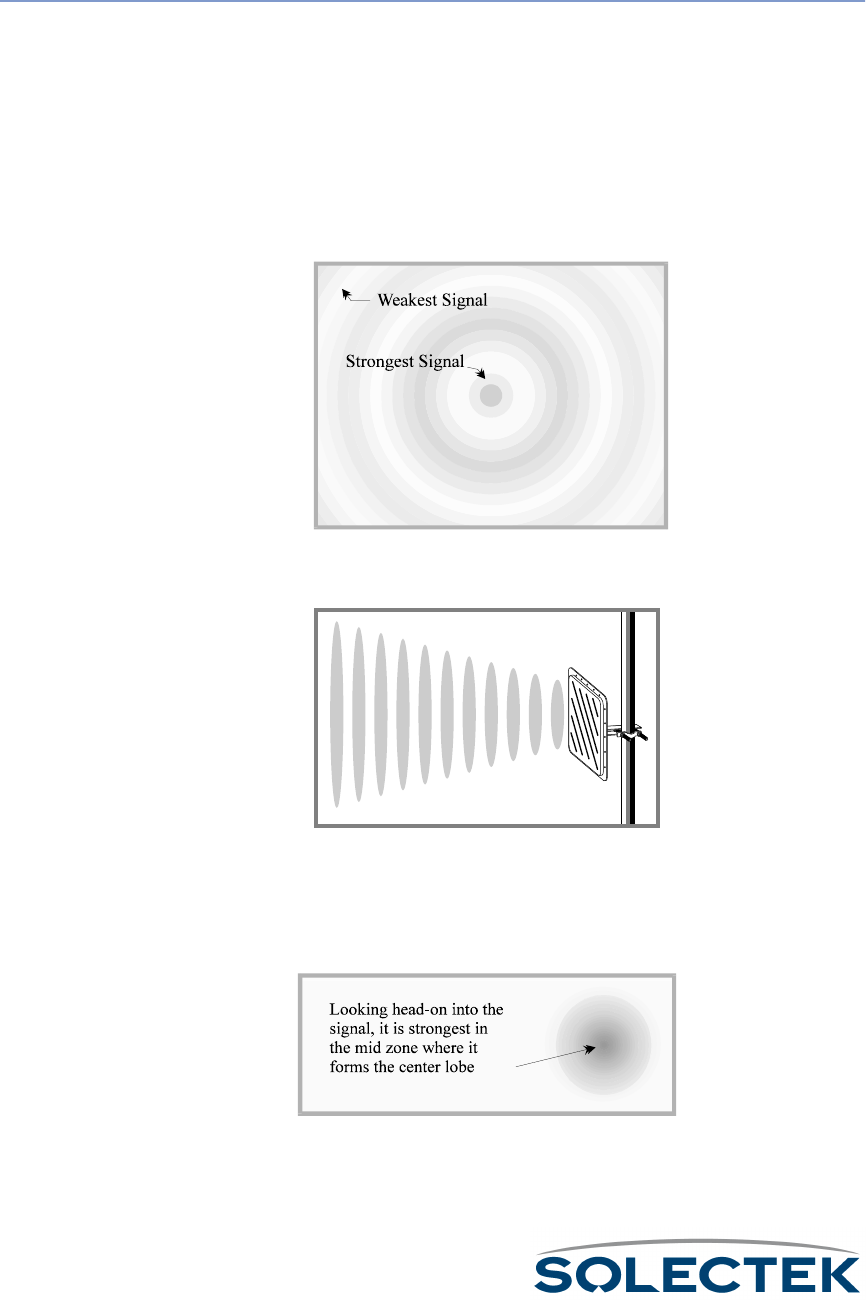
198
Basic Concepts
Radio Signals To visualize radio (RF) waves, consider the waves created when an object moves in
water. Water waves are strongest near their source, but they decrease in size as they
spread in all directions.
Radio waves fan out from their source in a similar manner. They travel best in empty
space, but they can also pass through gasses, such as air, and many other substances.
The lower the frequency of an RF signal, the more substances it can penetrate. The
ability of a directional antenna to focus radio waves is analogous to a magnifying glass
focusing sunlight into a very concentrated hot spot.
A directional antenna focuses the waves in one direction. It forms them into a conical
shape that makes them stronger and enables them to travel greater distances.
In the same way that light is focused by a magnifying glass, an RF signal shaped by an
antenna is strongest within a narrow area at the center of the cone. We call this area
the center lobe. For optimum long-distance reception, an antenna must be aligned to
receive the center lobe signal, and the signal path must be free of obstructions.
The signal forms a cone as
it leaves the antenna.
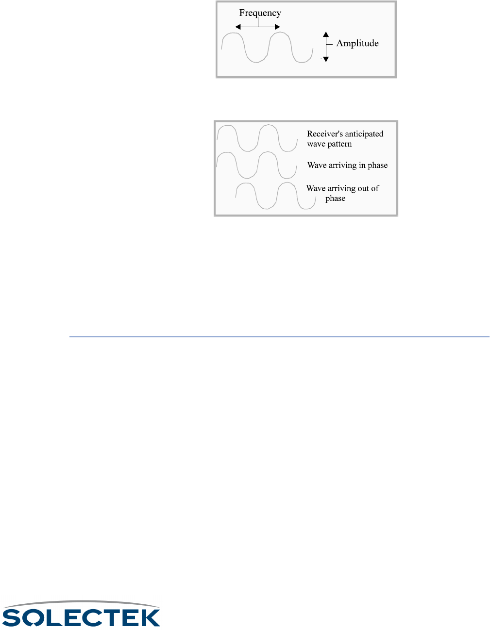
Basic Concepts
199
Frequency is the cycling rate of the signal wave. Amplitude is the height or strength of
the signal wave.
A radio can be tuned to a frequency so that the receiver is aligned with the peaks and
valleys of the RF wave. The receiver can then detect when the wave is out of phase.
Radio waves can carry messages in different ways. The radios in our homes and cars
convey sounds in a continuous stream (analog). The signals are strong, and the sounds
are inscribed in the wave as small variations in the amplitude (AM) or frequency (FM).
Phase Shift Key. There are also many ways to carry digital radio signals. One of the
common choices is Phase Shift Key (PSK). PSK shifts the phase of the signal to indicate
the status for each bit of data in the message. Digital, on/off, phase-shift signals are eas-
ier to decipher than the countless variations in an analog sound signal.
ISM Bands The FCC regulates the available frequencies to support a maximum number of users.
By placing limits on signal strength (wattage and gain), the FCC has been able to
accommodate the needs of multiple broadcasters in high-use areas with three small
bands of frequency. If you comply with FCC restrictions, you may broadcast within the
Industry, Science, and Medicine (ISM) bands without a license. The ISM bands include
the 2.4 GHz band, the 902-928 MHz band, and the 5.725-5.850 GHz band.
Solectek products are approved for unlicensed broadcasting within the ISM bands if
used in the packaged configurations approved by the FCC. To avoid FCC penalties and
maintain your warranty, you must use Solectek products in their FCC-approved config-
urations. It is illegal to substitute cables, antennas, or other system components.
2.4 GHz Frequency Characteristics. The 2.4 GHz band is good for long-distance
transmissions. It is rarely affected by static interference. There are multiple channels
within the 2.4 GHz band.

200
Spread Spectrum Spread spectrum spreads the transmission over different frequencies within its assigned
bands. There are four variations of spread spectrum technology, but for internetwork-
ing purposes Direct Sequence Spread Spectrum (DSSS) with DPSK is the one most
frequently used. DSSS continuously distributes the signal across a portion of the fre-
quency band. DSSS resists interference from other RF signals, static from nearby elec-
tronic devices, and fading. DSSS is also highly secure because the signal appears as
noise to non-DSSS receivers or DSSS receivers that are set to process a different spec-
trum.
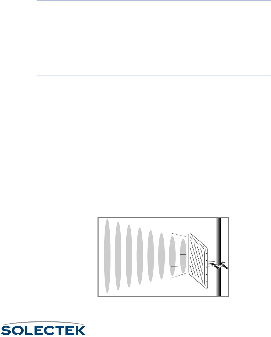
Units of Measure
201
Units of Measure
Attenuation and
Gain
Attenuation is a decrease in amplitude due to signal absorption or dispersion. Gain is an
increase in amplitude due to different forms of signal enhancement, such as the use of an
antenna to focus the signal. Amplitude and gain are measured in decibels (dB).
Antenna gain is measured relative to the strength of the signal you would receive at any
given distance using an antenna with no gain (such as a dipole or theoretic Isotropic
antenna).
The antennas at both ends of the link can enhance signal gain. The total gain for a connec-
tion between two antennas is the product of the gains for both antennas.
Signal
Measurement
To measure the size and strength of a signal meaningfully, we must consider the following:
• A signal widens with distance. To calculate the height and width of a signal, we must
know the distance from its source.
• A signal has no distinct outer edge. It is strongest in a narrow focused area (center
lobe), and it fades out gradually as distance increases from the center lobe.
How we measure the cone –
How we measure the cone –How we measure the cone –
How we measure the cone – To indicate the shape of the cone, we measure its expansion
in degrees.
How we measure signal strength –
How we measure signal strength –How we measure signal strength –
How we measure signal strength – We measure signal strength relative to the center point
where the signal is strongest, but we generally do not say how strong the signal is at that
point.
How we measure signal width –
How we measure signal width –How we measure signal width –
How we measure signal width – To avoid measuring from a nebulous edge, we measure
across the center point at different bands of signal strength. The number of decibels (dB
units) indicates threshold points relative to the center point.
For example, the beam width of the Solectek dish antenna we define as 17.5× maximum
at 3 dB elevation. Three dB is a threshold within the cone where the signal’s strength is
50% lower than its strength at the center. The drawing below shows the beam width at
different dB increments relative to the center of a signal formed by a dish antenna.
Decibel. The decibel (dB) is used as a measure of both attenuation and gain.
3 dB = 50% signal strength
1 dB = 80% signal strength
center lobe = 100% signal strength
1 dB = 80% signal strength
3 dB = 50% signal strength

202
It measures signal strength relative to some type of reference signal. Decibel measure-
ments are often referenced to the following values:
• The signal at its source
• The center point in the cone radiating from a directional antenna at any dis-
tance from its source.
• One milliwatt. dBm is the unit of measure used when signal strength is mea-
sured in decibels relative to one milliwatt.
• An antenna with no gain. dBi is the unit of measure used when signal strength
is measured in decibels relative to a fictitious isotropic antenna with no gain.
The decibel is a logarithmic measure calculated in base-ten. At 3 dB, a signal has half
the strength of the center lobe signal (not one-third the strength), and a gain of six dBi
is four times stronger than the signal from an antenna with no gain (not six times
stronger).
EIRP. Effective Isotropic Radiated Power (EIRP) is a measure of source signal strength
that combines broadcasting power (measured in watts) with the effect of antenna signal
gain (measured in dBi).
Fading. Temporary reductions in received signal strength are known as fading. Fading
normally results from intermittent interference. Fade margin is a margin of extra signal
strength built into the system to compensate for fading. For terrestrial links, the most
common cause of fading is multipath (deflected signals arriving out of phase) and foliage
within the signal path.
Interference. Interference refers to anything that blocks or degrades an RF signal.
There are three basic forms of interference:
• Atmospheric interference can result from sky noise or lightning in the signal
path.
• RF interference is generally caused by nearby activity in the same RF band (in-
band interference). Also very strong out-of-band activity can interfere with an
RF signal. Any wireless equipment can be a potential source of interference.
• Objects in the signal path can cause interference. The bending of signals as
they pass around obstructions or are deflected by them is known as diffraction.
Diffraction can damage signal quality if the diffracted signals arrive out of phase.
A glass window can attenuate the signal to some extent. Some types of mir-
rored glass can almost totally block the signal. Signals passing through the side
of a wooden building or a forest are also attenuated. Wet leaves can affect a
signal substantially. The success of an RF link depends on a clear line of sight.

Connection Types
203
Connection Types
LAN. A Local Area Network (LAN) links workstations, processors, and other equip-
ment within a local area, such as the inside of a building.
WAN. A Wide Area Network (WAN) is a network with connections spanning
broader distances than a LAN and typically with connections to the Public Switched
Telecommunications Network (PSTW). A WAN might connect locations in different
buildings or different geographic regions.
Internetwork. An internetwork is formed by linking networks to other networks or
devices. For example, a link between local area networks in different buildings creates
an internetwork.
Point-to-Point. A point-to-point connection is a direct link between locations.
Multipoint. A network or internetwork with multiple sites. A large multipoint con-
nection generally uses a central site to pass messages between the locations, and the
individual locations (substations) have direct connections to the central site, but not to
each other.

204
Antennas
Antennas come in different configurations to serve different needs. To span large dis-
tances, you must narrow the signal into a focused beam. The more focused is the sig-
nal, the greater is the gain. Since narrowing the signal increases the gain, you are
allowed to exceed six dB only if you reduce the power to less than 1 watt under FCC
rule Part 15.247. On the other hand, a 360o omnidirectional antenna has only a four-
fold gain, so it can use the maximum allowable one watt of power.
Antenna Types Directional. A directional antenna focuses the signal into a narrow beam. For 2.4
GHz systems, dish antennas achieve the highest gain and span the greatest distances.
Solectek’s dish antenna has 21 dBi of gain, and when using a transmit power of 15 dBm
(a small fraction of one watt) the EIRP is 36 dBm (the FCC maximum allowable). In the
902-928 MHz range, yagi antennas achieve the highest gain and span the greatest dis-
tances.
In addition to concentrating signal strength, directional antennas also:
• Reduce the strength of second Fresnel zone reflections, thus reducing the
potential for interference.
• Reduce interference from other RF devices within the same frequency range
at distances closer than the target antenna.
Multidirectional. Multidirectional antennas are used for connections where several
interfacing antennas are located in the same general direction. To achieve directionality
with a 2.4 GHz system, Solectek uses an antenna with a sectoral. Because multidirec-
tional antennas have a more focused beam than omnidirectional antennas, they
achieve higher gain and have greater spanning distances.
Omnidirectional. Omnidirectional antennas are used for connections where the
interfacing antennas are located in opposing directions. Because the focus of an omni-
directional antenna is 360 degrees, it has less gain and spans a smaller distance than
other types of antennas.
Antenna Alignment Antenna Polarization. To improve the isolation between adjacent antenna installa-
tions, in addition to using different channels, you can change polarization. Consult your
Solectek systems engineer for specific details.
Fresnel Zones. Waves can be deflected by objects in their paths. If a wave from an
outer band of the cone (see Radio Signals) is deflected back through the center lobe, it
can either strengthen that signal or reduce its strength, depending on how the waves

Antennas
205
align when they collide. A glancing deflection changes the angle of the wave very little,
so it remains generally in phase with the wave at the center lobe.
Within the signal span, there are zones where deflected signals are generally in phase
with the center lobe signal, and there are other zones where deflected signals are gen-
erally out of phase with the center lobe signal. We refer to these zones as Fresnel
(frËnl) zones.
The first Fresnel zone surrounds the center lobe where the RF signal is strongest. If
more than 40% of the first Fresnel zone is obstructed, your RF line of sight is not suffi-
ciently clear. In the first Fresnel zone and all the odd numbered Fresnel zones,
deflected signals are generally in phase with or the center lobe signal.
In the second Fresnel zone, and all even-numbered Fresnel zones, deflected signals are
up to 180× out of phase with the center lobe signal. Signals deflected from the second
Fresnel zone can cause Inter Symbol Interference (ISI) which can result in great losses
of the center lobe signal. To avoid this problem, you must place your antenna at a
height that is out of range from F2 deflections. (An antenna can be set too high as well
as too low.) Where deflection and diffraction from ground-based objects cause inter-
ference, even a small relocation of the antenna often produces a substantial improve-
ment.
Line of Sight. Radio transmission requires a clear path between antennas known as
radio line of sight. It is necessary to understand the requirements for radio line of sight
when designing a network using Solectek equipment. Radio line of sight and visual
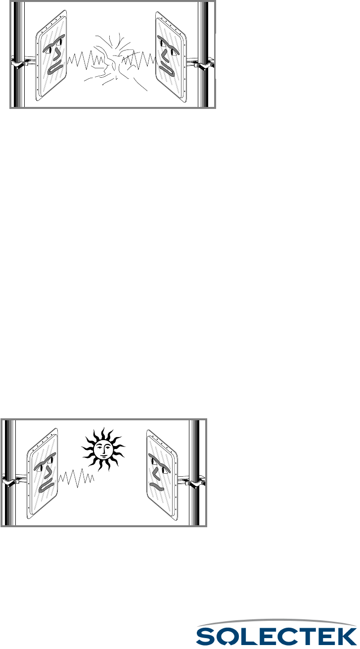
206
(optical) line of sight are different. Consult your Solectek dealer or Solectek’s Web site
at www.solectek.com for more information.
If any one station is beyond the listening range of any other station, both of these sta-
tions might transmit simultaneously. The result is called a collision, and it generally
results in lost data.
The CSMA/CA protocol was created to resolve this problem.
CSMA/CA. Some manufacturers use Carrier Sense Multiple Access with Collision
Avoidance (CSMA/CA) protocol to avoid collisions in communications between sub-
stations on lightly loaded wireless systems. Solectek products do not use CSMA/CA,
however, because this protocol suffers from severe limitations described in the follow-
ing paragraphs.
To avoid collisions, a station wanting to transmit listens first for other stations. If the air-
way is busy, it tries again later. As more sites are added, throughput demands increase,
and stations may repeatedly try to send data as other stations are transmitting. Under
these circumstances CSMA/CA collision avoidance breaks down, and the following
problems can occur:
Capture effect –
Capture effect – Capture effect –
Capture effect – Sites with strong signals overpower sites with weak signals and domi-
nate the bandwidth used for transmission.
Collision Avoidance locks –
Collision Avoidance locks – Collision Avoidance locks –
Collision Avoidance locks – Stations waiting for an open airway get stuck in Collision
Avoidance mode.
“Hidden Node” Effect –
“Hidden Node” Effect – “Hidden Node” Effect –
“Hidden Node” Effect – All stations must have clear radio line of sight to all other sta-
tions to have direct communications. This is often impossible to achieve.
Because of these limitations, CSMA/CA has problems supporting wireless inter-building
applications that require continuous, high data throughput between multiple sites. Due
to these CSMA/CA limitations, Solectek products DO NOT use CSMA/CA.
Signal collisions occur
when two stations trans-
mit at the same time.
If strong stations over-
power weaker stations,
weaker stations may never
get to broadcast.

Antennas
207
RF-DLC Base Station / Substation Polling Protocol. To overcome the CSMA/
CA limitations mentioned above, Solectek has developed a base station / substation
polling protocol called RF-DLC. The RF-DLC protocol allows for higher throughput
under heavy load than systems using CSMA/CA or other similar protocols.
The base station allocates substation access to the internetwork. It polls each substation
and allows a designated time for the substation to respond. This polling protocol has
the following advantages:
• To avoid the capture effect where strong stations dominate, the base station
partials out time to substations needing to broadcast.
• If a connection is lost, the disconnected station does not respond to polling.
When a station times out without responding, the connection is recovered.
• Individual substations on the network do not need to listen to each other to
avoid collisions. Since the base station manages all broadcasts, no two substa-
tions can transmit at the same time.

208
Protocols
IP. Internetwork Protocol (IP) is a routing protocol used to direct both outgoing and
incoming messages based on an internetwork addresses.
Spanning Tree. Spanning Tree Protocol (STP) is a bridging protocol based on an
IEEE 802.1 standard technique for ensuring efficient paths between bridged networks.
Where multiple paths exist, the Spanning Tree algorithm calculates the best path to
use. If that path deadends or gets mired in a loop, STP reconfigures the network to use
another path.

Equipment
209
Equipment
Console A VT-100 terminal or workstation with VT-100 terminal emulation capability and ter-
minal emulation software (such as Hyperterm).
Protocol Analyzer A protocol analyzer or LAN analyzer is a device used to analyze LAN system activity. It
receives all frames transmitted over the LAN, regardless of address, and provides a
detailed analysis. This tool is useful for learning the quantity of traffic and the character-
istics and protocols of the data being processed by a wireless bridge.
Spectrum Analyzer A spectrum analyzer is a tunable instrument which graphically displays signals it detects
within a selected band of the RF spectrum. The spectrum analyzer can be used for sev-
eral purposes during site surveys or for problem diagnosis. For example, by detecting
an existing signal in a broadcast band you want to use, the spectrum analyzer can alert
you to a potential source of interference.
Topological Map A topological map allows you to study the terrain between antenna sites that are out of
view from one another. You can purchase inexpensive topological maps from the US
Geographical Survey, Denver, Colorado 802225.

210
Site Survey
A site survey provides the studies and analysis needed to assure success in a wireless
internetwork design. A site survey is particularly important for long distance and multi-
point connections, and it is essential if there is any doubt whether a wireless internet-
work is feasible or practical for the application.
Site surveys may include few or many studies, depending on the difficulty of the instal-
lation and the questions to be answered. Two survey study options include terrain
analysis and spectrum analysis (see spectrum analyzer). The site survey may include
any or all of the following information:
• The types of antennas and other components best suited to achieve the dis-
tance and multipoint spanning requirements
• How high the antennas must be to avoid obstructions and out-of-phase
deflections
• Potential sources of interference in the alternative RF bands
• The best configuration (base/sub station or point-to-point)
• The best location for each component
• The federal, state, and local requirements that apply for mast construction and
electrical grounding in your area.
Terrain Analysis Terrain analysis charts the terrain between antennas in order to calculate the best loca-
tion and height for the antennas. This calculation must consider several factors. For
example:
• The height of the lower half of the first Fresnel zone between the antennas rel-
ative to the highest obstructions
• The distances spanned, the number of sites linked, and the types of antennas
needed to reach all the sites
• The margins required to achieve your reliability objectives
The following chart shows 100% of the lower half of the first Fresnel zone for a link
spanning nearly 13 miles with recommended antenna heights of 240 and 70 feet.
Although a mountain is shown blocking part of the F1 signal path between the anten-
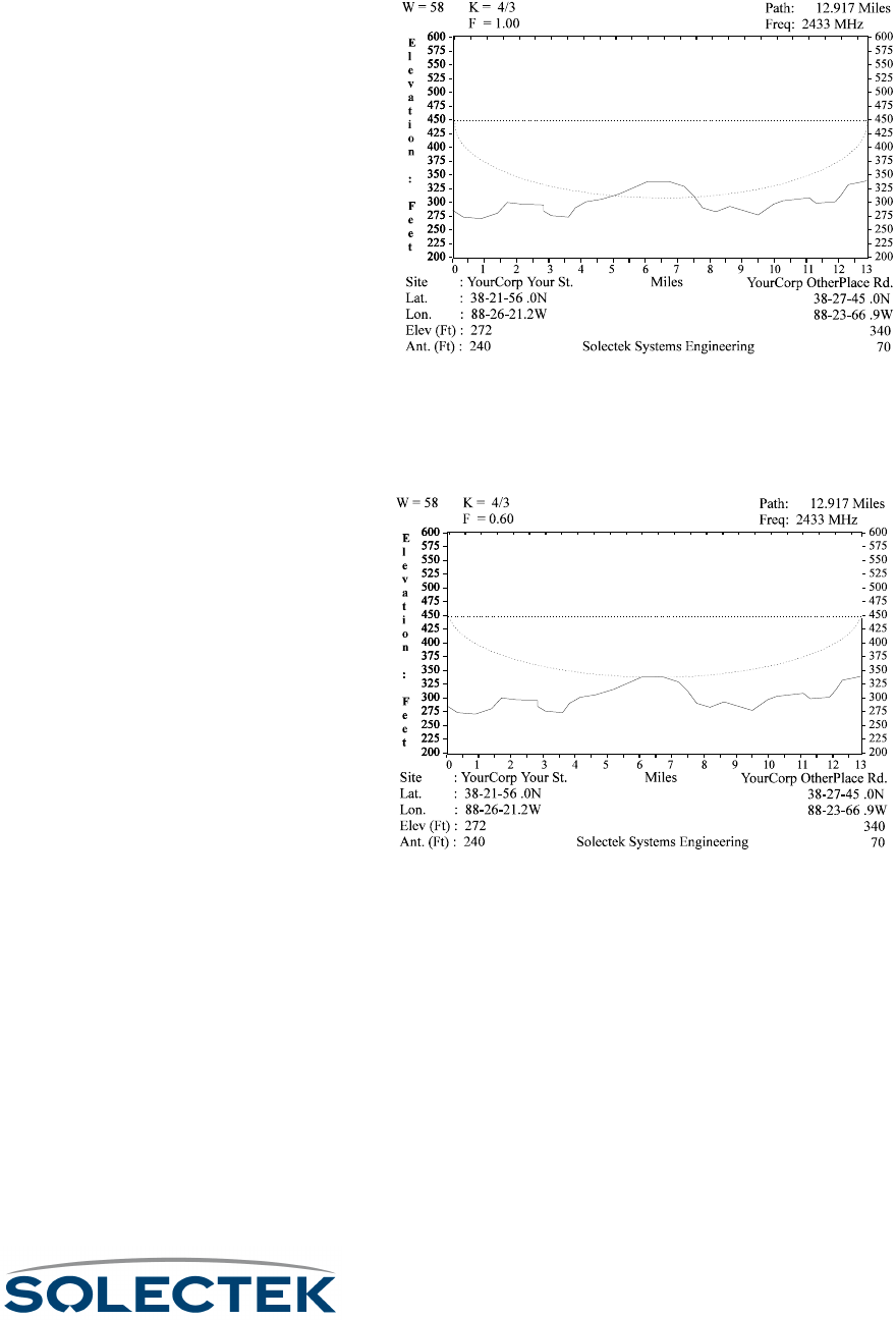
Site Survey
211
nas, it is not essential to maintain a free space path of 100%. Note that this chart does
not show ground cover objects, such as trees or buildings.
The next chart shows the same terrain with the same antenna heights, but it calculates
based on the recommended minimum limit of 60% (.6) free-space in the lower half of
the F1 zone. This graphically shows the minimum RF line of sight requirements for the
antennas.

212

213
Appendix K:
Appendix K: Appendix K:
Appendix K:
Skyway Antennas
Skyway AntennasSkyway Antennas
Skyway Antennas
A good wireless connection depends on the antenna you choose and mount.
This chapter contains information about the following antennas:
7002301: 6 dBi Omni Directional Antenna ..................... 214
7002401: 11 dBi Omni Directional Antenna ................... 216
7002501: 16 dBi Outdoor Flat Panel Directional Antenna 218
7002601: 17 dBi Outdoor Flat Panel Directional Antenna 220
7002701: 22 dBi Outdoor High gain Flat Panel Directional
Antenna.......................................................................... 222
7002801: 8 dBi Indoor/Outdoor Patch Antenna.............. 224
7002901: 12 dBi 110 ° Outdoor Sectorial Antenna ......... 226
Note: All omni antennas should be mounted above the SkyWay bridge/router, near the very
top of the mast.
Note: Antennas are not shown to scale.
Note: Solectek’s antennas are all weather units and we recommend that a professional
installer perform the installation.
Note: All SkyWay Series antenna are supplied with a standard 8 ft coaxial pigtail (LMR400) to
interface with the transceiver.
Installation Instructions

214
7002301: 6 dBi Omni Directional Antenna
Specifications
Frequency 2.4000 to 2.4835 GHz
Net Gain 6.0 dBi
3dB Beam width (E. Plane) 20 °
Front to Back ratio N/A – Omnidirectional
Polarity Vertical, fixed
Cross polarity rejection n/a
VSWR (Average) 1.5:1
Impedance 50 τ
Coaxial pigtail length (to ODU)
Rated wind velocity 125 mph (201 kph)
Wind loading @ rated wind velocity 3.76 lbs (1.71 kg)
Elevation adjustment n/a
Size 10.5 in l x 5/8 in dia.
(266.7 mm l x 15.88 mm dia)
Weight 0.375 lbs (.1701 kg)
Radome UV stabilized fiberglass
Mounting hardware Stainless steel clamp
Mast diameter .75 in to 3.0 in (19.05 mm to
76.2 mm) OD pipe

7002301: 6 dBi Omni Directional Antenna
215
Wall Mount
Note. Since the antenna must be mounted above the SkyWay, do not use the wall
mount if the SkyWay is mounted on a mast.
1. Prepare the wall as necessary (e.g., measure and drill holes, set screw anchors).
2. Insert and tighten two screws through pre-drilled mounting holes.
Mast Mount
1. Attach the antenna to the mast with two hose clamps seated in grooves on the
bracket.

216
7002401: 11 dBi Omni Directional Antenna
Specifications
Frequency 2.4000 to 2.4835 GHz
Net Gain 11.0 dBi
3dB Beam width (E. Plane) 12o
Front to Back ratio N/A – Omnidirectional
Polarity Vertical, fixed
Cross polarity rejection n/a
VSWR (Average) 1.5:1
Impedance 50 τ
Coaxial pigtail length (to ODU)
Rated wind velocity 135 mph (217 kph)
Wind loading @ rated wind velocity 4.0 lbs (1.81 kg)
Elevation adjustment n/a
Size 37 in l x .7 in dia.
(939.8 mm l x 17.78 mm dia.)
Weight 0.88 lbs (0.4 kg)

7002401: 11 dBi Omni Directional Antenna
217
Wall Mount
Note. Since the antenna must be mounted above the SkyWay, do not use the wall
mount if the SkyWay is mounted on a mast.
1. Prepare the wall as necessary (e.g., measure and drill holes, set screw anchors).
2. Use two screws to attach the bracket to a backplate, then attach the back plate to
the wall
Mast Mount
Use the bracket and U-bolt assembly to attach the cable to the mast.
Radome UV stabilized fiberglass
Mounting hardware Galvanized and stainless steel clamp
Mast diameter .75 in to 2.0 in (19.05 mm to
50.8 mm OD pipe
Specifications (Continued)

218
7002501: 16 dBi Outdoor Flat Panel Directional
Antenna
Note: This antenna is designed to be used as a bridge between two networks or for point-to-
point communications in the ISM band (2.4 GHz) only.
Specifications
Frequency 2.4000 to 2.4835 GHz
Net Gain 16.0 dBi
3dB Beam width (E. Plane)
Front to Back ratio
Polarity Vertical (default) or horizontal; field
changeable
Cross polarity rejection
VSWR (Average) 1.5:1
Impedance 50 τ
Coaxial pigtail length (to ODU)
Rated wind velocity
Wind loading @ rated wind velocity
Elevation adjustment
Size
Weight

7002501: 16 dBi Outdoor Flat Panel Directional Antenna
219
Wall Mount
Note. Since the antenna must be mounted above the SkyWay, do not use the wall
mount if the SkyWay is mounted on a mast.
1. Prepare the wall as necessary (e.g., measure and drill holes, set screw anchors).
2. Use four screws to attach the provided wall mount to the wall.
Mast Mount
1. Attach it to the mast with a U-clamp.
2. Tighten the clamp with your fingers.
Radome
Reflector material
Mounting hardware
Mast diameter .75 in to 3.0 in (19.05 mm to
76.2 mm) OD pipe
Specifications (Continued)
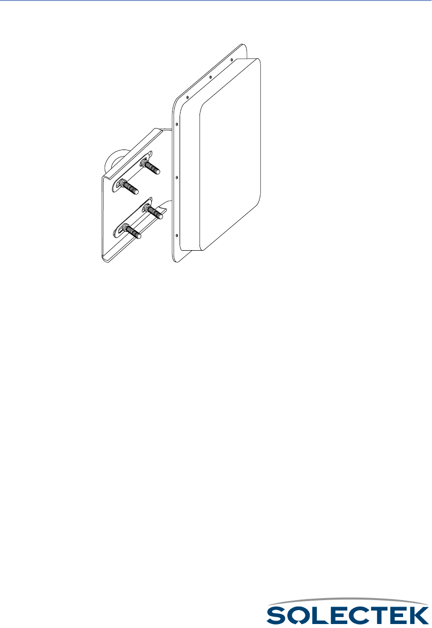
220
7002601: 17 dBi Outdoor Flat Panel Directional
Antenna
Note: This antenna is designed to be used as a bridge between two networks or for point-to-
point communications in the ISM band (2.4 GHz) only.
Specifications
Frequency 2.4000 to 2.4835 GHz
Net Gain 17.0 dBi
3dB Beam width (E. Plane)
Front to Back ratio
Polarity Vertical (default) or horizontal; field
changeable
Cross polarity rejection
VSWR (Average) 1.5:1
Impedance 50 τ
Coaxial pigtail length (to ODU)
Rated wind velocity
Wind loading @ rated wind velocity
Elevation adjustment

7002601: 17 dBi Outdoor Flat Panel Directional Antenna
221
Wall Mount
Not available.
Mast Mount
Note: Use a 9/16 in wrench to tighten the bolts.
1. Use four bolts to attach the lower part of the bracket to the square antenna.
2. Adjust the tilt on the center section using the 2 bolts.
3. Use four bolts to anchor the bracket to the mast with two U-bolts.
Size
Weight
Radome
Reflector material
Mounting hardware
Mast diameter .75 in to 3.0 in (19.05 mm to
76.2 mm) OD pipe
Specifications (Continued)
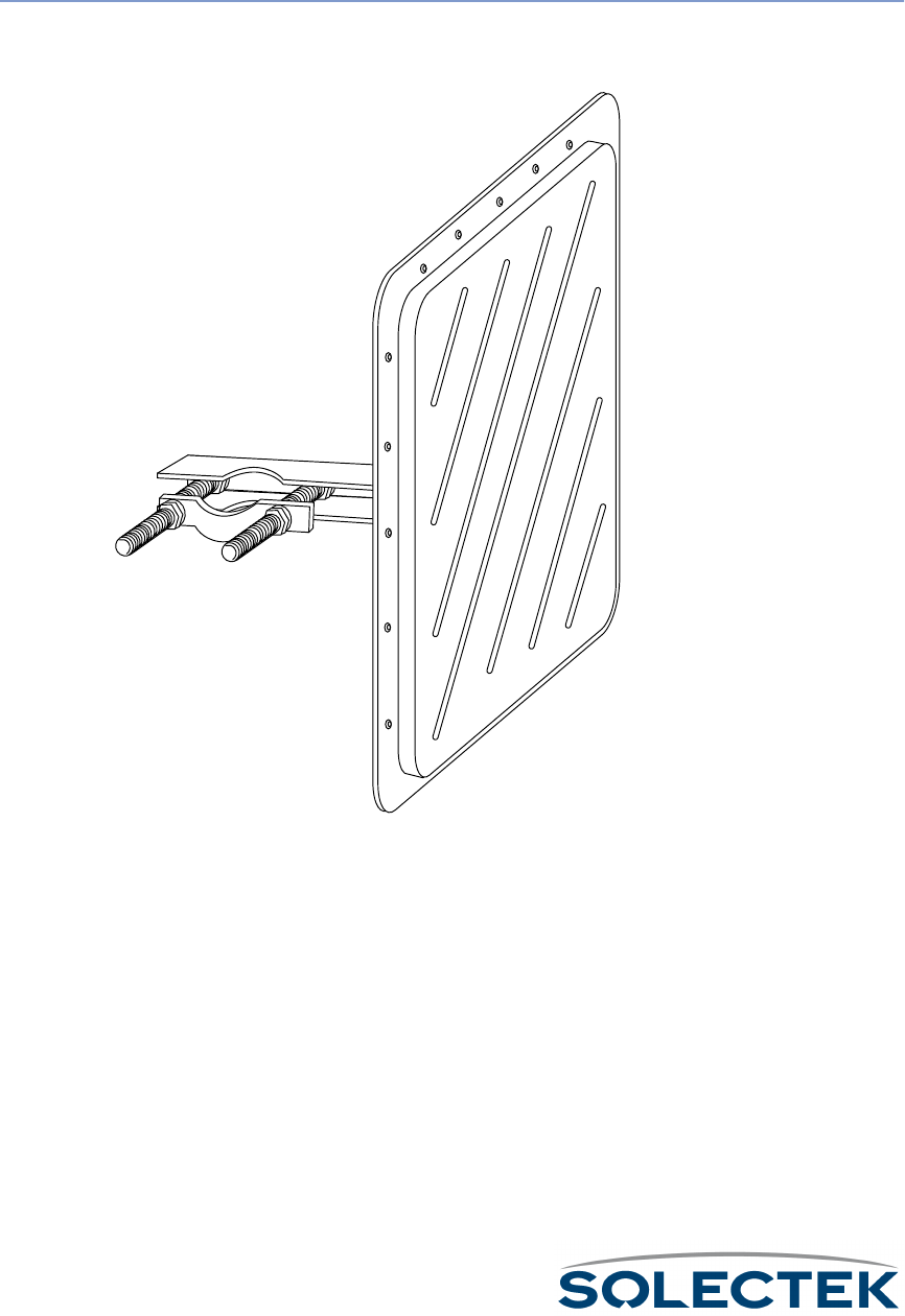
222
7002701: 22 dBi Outdoor High gain Flat Panel
Directional Antenna
Note: This antenna is designed to be used as a bridge between two networks or for point-to-
point communications in the ISM band (2.4 GHz) only.
Specifications
Frequency 2.4000 to 2.4835 GHz
Net Gain 21.2 dBi
3dB Beam width (E. Plane) 10 °
Front to Back ratio > 32 dB
Polarity Vertical (default) or horizontal; field
changeable
Cross polarity rejection > 30 dB

7002701: 22 dBi Outdoor High gain Flat Panel Directional Antenna
223
Wall Mount
Not available.
Mast Mount
1. Attach the square part of the bracket to the square antenna with two bolts and
washers.
Attach two bolts at the end of the boom to clamp the fixture to the mast.
VSWR (Average) 1.5:1
Impedance 50 τ
Coaxial pigtail length (to ODU) 36 in (914.4 mm)
Rated wind velocity 100 mph/140 mph (161 kph/225 kph)
Wind loading @ rated velocity 30 lbs/140 lbs (13.61 kg/63.5 kg)
Elevation adjustment 45 °
Size 24.0 in x 24.0 in x 1.5 in
(609.6 mm x 609.6 mm x 38.1 mm)
Weight 15 lbs (6.8 kg)
Radome n/a
Reflector material Aluminum/plastic
Mounting hardware aluminum/steel clamp
Mast diameter 2.375 in (60.33 mm) OD pipe
Specifications (Continued)

224
7002801: 8 dBi Indoor/Outdoor Patch Antenna
Note: This antenna is designed to be used as a bridge between two networks or for point-to-
point communications in the ISM band (2.4 GHz) only.
Specifications
Frequency 2.4000 to 2.4835 GHz
Net Gain 8.0 dBi
3dB horizontal beam width 60 °
3 dB vertical beam width 60 °
Front to Back ratio 25 dB
Polarity Linear
Cross polarity rejection n/a
VSWR (Average) 1.5:1
Impedance 50 τ
Connector N female
Rated wind velocity 125 mph (201 kph)
Wind loading @ rated wind velocity 20 lbs (9.072 kg)
Elevation adjustment n/a
Size 4.77 in x 1.14 in x 6.25 in
(121.2 mm x 29 mm x 158.8 mm)
Weight 1.5 lbs (.68 kg)
Radome UV stabilized
Mounting hardware screw mount base, snap-in radome

7002801: 8 dBi Indoor/Outdoor Patch Antenna
225
Wall Mount
Note. Since the antenna must be mounted above the SkyWay, do not use the wall
mount if the SkyWay is mounted on a mast.
1. Prepare the wall as necessary (e.g., measure and drill holes, set screw anchors).
2. Insert and tighten two screws through pre-drilled mounting holes.
Mast Mount
1. Attach the antenna to the mast with two hose clamps seated in grooves on the
bracket.
2. Tighten the clamps.
3.
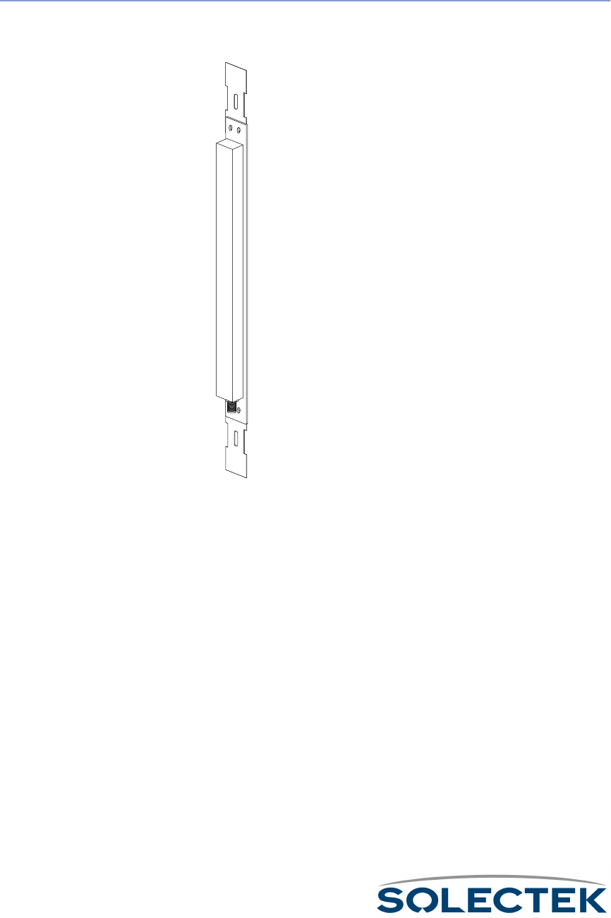
226
7002901: 12 dBi 110 ° Outdoor Sectorial Antenna
Note: This antenna is designed to be used as a bridge between two networks or for point-to-
point communications in the ISM band (2.4 GHz) only.
Specifications
Frequency 2.4000 to 2.4835 GHz
Net Gain 12.0 dBi
3dB Beam width (E. Plane) 12 °
Front to Back ratio > 17 dB
Polarity Vertical, fixed
Cross polarity rejection n/a
VSWR (Average) 1.5:1
Impedance 50 τ
Coaxial pigtail length (to ODU)
Rated wind velocity 124 mph (200 kph)

7002901: 12 dBi 110 ° Outdoor Sectorial Antenna
227
Wall Mount
Note. Since the antenna must be mounted above the SkyWay, do not use the wall
mount if the SkyWay is mounted on a mast.
1. Prepare the wall as necessary (e.g., measure and drill holes, set screw anchors).
2. Attach the two mounting brackets to anchor the frame at top and bottom.
3. Insert and tighten two screws through pre-drilled mounting holes.
Mast Mount
1. Attach the two mounting brackets to anchor the frame at top and bottom.
2. Attach the antenna to the mast with two hose clamps seated in grooves on the
brackets.
3. Tighten the clamps.
Wind loading @ 140 mph 6.6 lbs (2.99 kg)
Elevation adjustment n/a
Size 20 in x 2 in x 1.2 in
(508 mm x 50.8 mm x 30.48 mm)
Weight 0.55 lbs (.25 kg)
Radome ASA, UV stabilized
Reflector material Powder-coated aluminum
Mounting hardware stainless steel worm-type clamp
Mast diameter .75 in to 3.0 in (19.05 mm to
76.2 mm) OD pipe
Specifications (Continued)

228

229
Index
IndexIndex
Index
Symbols
(db), decibel 201
(female dc jack), dc power cable 182
(psk), phase shift key 199
Numerics
10 base-t/100 base-tx (Ethernet cable
RJ-45) 184
2.4 ghz frequency characteristics 199
7002301 6 dbi omni directional antenna 214
7002401 11 dbi omni directional antenna 216
7002501 16 dbi outdoor flat panel directional antenna 218
7002601 17 dbi outdoor flat panel directional antenna 220
7002701 22 dbi outdoor high gain flat panel directional antenna
222
7002801 8 dbi indoor/outdoor patch antenna 224
7002901 12 dbi 110 ° outdoor sectorial antenna 226
A
accept status of a sub station, validating 81
access levels, adding users and setting 62
accessing the SkyWay bridge/router 22
activity, checking icmp 161
adding
users 62
adding users and setting access levels 62
address resolution protocol table, checking the 163
addresses, obtaining IP 69
addresses, setting up IP 69
administration console 11
administration console, connecting to the 51
adp discovery process 66
ADP substation configuration 81
adp, disabling 66
adp, enabling 65
alignment and RF link verification, antenna 55
alignment, antenna 204
amplitude 199
analysis, terrain 210
analyzer, protocol 209
analyzer, spectrum 209
antenna 204
alignment 204
polarization 204
antenna alignment 204
antenna alignment and RF link verification 55
antenna polarization 204
antenna types 204
directional 204
multidirectional 204
omnidirectional 204
antenna, connecting an 49
antenna, grounding SkyWay and the 47
antenna, mounting the 46
antenna, selecting the 45
antenna, setting up the 45
antennas 204
application from reset, starting the BIOS 18
application from runtime, starting the BIOS 18
application, BIOS 18
application, point-to-point or multi-point 8
ARP table 163
as a base station, configuring the SkyWay 69
as a sub station, configuring the SkyWay 77
at commands, example 23
attached to the SkyWay, to configure a modem 22
attenuation 201
attenuation and gain 201
audience, intended 2
automatic discovery protocol 65
available, configuration features 58
available, monitoring features 126
available, SNMP features 103
B
bands, ISM 199
base port status, checking RF-DLC 140
base station / substation polling protocol, mst/sm 207
base station / substation polling protocol, RF-DLC 207
base station states 164
base station, configuring the SkyWay as a 69
base sub ports, configuring the 80
basic concepts 198
before installing 28
bench test 32
bench test results 174
bench test, minimum configuration settings and factory defaults
for 32
bench test, performing the 33
BIOS application 18
BIOS application from reset, starting the 18
BIOS application from runtime, starting the 18
BIOS configuration menu 19
BIOS diagnostics 104
BIOS main menu 18
BIOS system configuration 20
bootp 98
bridge
configuration 90

230
port configuration 92
port status 152
spanning tree status and 149
bridge and spanning tree status, checking 149
bridge port status, checking 152
bridge/router, accessing the SkyWay 22
bridged protocols 187
bridging 88
bridging screens 149
bridging table, transparent 156
bridging, enabling and disabling 88
C
cable (female dc jack), dc power 182
cable, copper 53
cable, fiberoptic 53
cables, routing connected 48
cabling, connecting 48
center lobe 198
changes that require cycling or resetting 16
changes, saving configuration 16
characteristics, 2.4 ghz frequency 199
checking bridge and spanning tree status 149
checking bridge port status 152
checking icmp activity 161
checking IP routing status 157
checking RF-DLC base port status 140
checking SNMP status and trap history 128
checking spanning tree port status 154
checking the address resolution protocol table 163
checking the error log 130
checking the Ethernet port status 134
checking the polling status 146
checking the RF port 137
checking the RF signal status 147
checking the serial port status 132
checking the status summary 168
checking the sub port status 143
client and server, the pc is the 117
client, SkyWay is the 117
client, SkyWay is the server and 117
client, the pc is the 117
clients and server, TFTP 117
command names, menu and 5
commands and responses, RF-DLC 67
commands, dot 14
commands, example at 23
common rows 15
component identification 11
concepts, basic 198
configuration
ADP substation 81
Ehternet transceiver 85
Ethernet port 83
general parameters 64
RF base port 74
RF base port sub 80
RF diagnostic port 73
RF sub port 78
serial port 24
serial transceiver 25
configuration changes, saving 16
configuration database service 21
configuration database, understanding the 16
configuration features available 58
configuration menu, BIOS 19
configuration parameters, setting system 59
configuration settings and factory defaults for bench test, mini-
mum 32
configuration summary 100
configuration summary, obtaining a 99
configuration, BIOS system 20
configuration, network 174
configuration, RF network 174
configure a modem attached to the SkyWay, to 22
configure the terminal for dialing to the SkyWay, to 22
configuring IP 93
configuring SkyWay 58
configuring the base sub ports 80
configuring the Ethernet port 83
configuring the Ethernet transceiver 85
configuring the IP ports 95
configuring the ports 69
configuring the serial port and serial transceiver 23
configuring the SkyWay as a base station 69
configuring the SkyWay as a sub station 77
configuring the TFTP server on SkyWay 119
connected cables, routing 48
connecting an antenna 49
connecting cabling 48
connecting to power 50
connecting to the administration console 51
connecting to your LAN 53
connection types 203
connection, modem settings for dial-up 22
considerations, safety 29
considerations, site 30
console 209
console cable (serial rs-422
db9) 183
console, administration 11
console, connecting to the administration 51
contents of the SkyWay package 10
control message protocol, internet 102
control screens, port status and 132
control screens, system status and 127
control, general status and 127
conventions, warnings 5
copper cable 53

231
csma/ca 206, 207
cycling or resetting, changes that require 16
D
database service, configuration 21
database, understanding the configuration 16
date and time, setting the system 64
dbi 202
dbm 202
dc jack), dc power cable (female 182
dc power cable (female dc jack) 182
decibel 201
decibel (db) 201
defaults for bench test, minimum configuration settings and facto-
ry 32
definitions, file 118
descrIPtion of the problem, detailed 173
descrIPtion, general 8
detailed descrIPtion of the problem 173
detection and recovery, error 68
diagnostics 104
diagnostics port, RF 73
diagnostics, BIOS 104
diagnostics, runtime 104
dialing to the SkyWay, to configure the terminal for 22
dial-up connection, modem settings for 22
directional 204
directory, file 111
disabling adp 66
disabling bridging, enabling and 88
discovery process, adp 66
discovery protocol, automatic 65
display information, how screens 15
displaying a list of users 63
displaying one record., screens 15
dot commands 14
dsss 200
E
editing fields 15
eirp 202
electrical safety guidelines 29
enabling adp 65
enabling and disabling bridging 88
equIPment 209
error detection and recovery 68
error log, checking the 130
Ethernet
port configuration 83
port status 134
transceiver configuration 85
transceiver status 136
Ethernet port status, checking the 134
Ethernet port, configuring the 83
Ethernet port. 11
Ethernet transceiver, configuring the 85
example at commands 23
F
factory defaults for bench test, minimum configuration settings
and 32
fading 202
features available, configuration 58
features available, monitoring 126
features available, SNMP 103
features, product 9
fiberoptic cable 53
field types 15
fields, editing 15
file definitions 118
file directory 111
file transfer protocol, trivial 116
file transfer utilities 112
files, sending and receiving 117
flowchart, symptom/action 172
frame types, RF-DLC 67
frequency 199
frequency characteristics, 2.4 ghz 199
fresnel zones 204
G
gain 201
gain, attenuation and 201
general descrIPtion 8
general parameters configuration 64
general safety guidelines 29
general status and control 127
information 173
ghz frequency characteristics, 2.4 199
grounding SkyWay and the antenna 47
guide, using this 3
guidelines, electrical safety 29
guidelines, general safety 29
H
history, checking SNMP status and trap 128
how screens display information 15
how to proceed 6
hyperjumps 5
I
icmp activity, checking 161
ICMP status 161
identification, component 11
information, how screens display 15
installing, before 28

232
intended audience 2
interference 202
internet control message protocol 102
internetwork 203
IP 208
address table 160
port configuration 95
protocol configuration 93
protocol status 157
static routes configuration 97
IP addresses, obtaining 69
IP addresses, setting up 69
IP ports, configuring the 95
IP routing 93
IP routing screens 157
IP routing status, checking 157
IP, configuring 93
ISM bands 199
J
jack), dc power cable (female dc 182
K
key (psk), phase shift 199
key, phase shift 199
L
LAN 203
analyzer 209
LAN, connecting to your 53
levels, adding users and setting access 62
line of sight 205
link verification, antenna alignment and RF 55
list of users, displaying a 63
lobe, center 198
log, checking the error 130
logical network map 174
M
main menu, BIOS 18
management protocols 187
management security parameters, setting network 59
management system parameters, setting network 61
map, logical network 174
map, topological 209
mast mount 215, 217, 219, 221, 223, 225, 227
mast, mounting to a 42
measure, units of 201
measurement, signal 201
menu and command names 5
menu structure, understanding the 13
menu, BIOS configuration 19
menu, BIOS main 18
menus and screens, navigating through 13
message protocol, internet control 102
minimum configuration settings and factory defaults for bench test
32
modem attached to the SkyWay, to configure a 22
modem settings for dial-up connection 22
monitoring features available 126
mount, mast 215, 217, 219, 221, 223, 225, 227
mount, wall 215, 217, 219, 221, 223, 225, 227
mounting the antenna 46
mounting the SkyWay unit 42
mounting to a mast 42
mounting to a wall 44
mst/sm base station / substation polling protocol 207
multidirectional 204
multi-level password security 123
multIPoint 203
multi-point application, point-to-point or 8
N
names, menu and command 5
navigating through menus and screens 13
network configuration 174
network configuration, RF 174
network management
security configuration 59
system configuration 61
network management security parameters, setting 59
network management system parameters, setting 61
network map, logical 174
new software version, uploading a 115
notes 5
O
obtaining a configuration summary 99
obtaining IP addresses 69
omnidirectional 204
one record., screens displaying 15
operations, remote 8
or multi-point application, point-to-point 8
or resetting, changes that require cycling 16
P
package, contents of the SkyWay 10
parameters configuration, general 64
parameters, setting network management security 59
parameters, setting network management system 61
parameters, setting system configuration 59
password security, multi-level 123
pc is the client and server, the 117
pc is the client, the 117
pc is the server., the 117

233
performing the bench test 33
phase shift key 199
phase shift key (psk) 199
ping utility 108, 109
point-to-point 203
point-to-point or multi-point application 8
polarization, antenna 204
polling 67
polling protocol, mst/sm base station / substation 207
polling protocol, RF-DLC base station / substation 207
polling status, checking the 146
port and serial transceiver, configuring the serial 23
port configuration
Ethernet 83
RF base 74
RF base sub 80
RF diagnostic 73
RF sub 78
serial 24
port states 88
port status and control screens 132
port status, checking bridge 152
port status, checking RF-DLC base 140
port status, checking spanning tree 154
port status, checking the Ethernet 134
port status, checking the serial 132
port status, checking the sub 143
port status, serial 132
port, checking the RF 137
port, configuring the Ethernet 83
port, RF diagnostics 73
port., Ethernet 11
ports, configuring the 69
ports, configuring the base sub 80
ports, configuring the IP 95
power 11
power cable (female dc jack), dc 182
power, connecting to 50
pre-installation procedures 30
problem, detailed descrIPtion of the 173
procedures, pre-installation 30
proceed, how to 6
process, adp discovery 66
product features 9
protocol
analyzer 209
csma/ca 207
protocol analyzer 209
protocol table, checking the address resolution 163
protocol, automatic discovery 65
protocol, internet control message 102
protocol, mst/sm base station / substation polling 207
protocol, RF-DLC base station / substation polling 207
protocol, the RF-DLC 65
protocol, trivial file transfer 116
protocols 208
csma/ca 206
mst/sm 207
routing 208
spanning tree 208
protocols, bridged 187
protocols, management 187
protocols, routed 187
R
radio
signals 198
radio signals 198
receiving files, sending and 117
record., screens displaying one 15
recovery, error detection and 68
remote operations 8
require cycling or resetting, changes that 16
reset, starting the BIOS application from 18
resetting the unit 16
resetting, changes that require cycling or 16
resolution protocol table, checking the address 163
responses, RF-DLC commands and 67
results, bench test 174
RF
base port configuration 74
sub port configuration 80
base radio test 105
diagnostic port configuration 73
port status 137
signal status 147
sub port configuration 78
sub radio test 107
transceiver configuration 72
RF diagnostics port 73
RF link verification, antenna alignment and 55
RF network configuration 174
RF port, checking the 137
RF signal status, checking the 147
RF. 11
RF-DLC
base port status 140
sub poll status 146
sub port status 143
RF-DLC base port status, checking 140
RF-DLC base station / substation polling protocol 207
RF-DLC commands and responses 67
RF-DLC frame types 67
RF-DLC protocol, the 65
RF-DLC screens 140
RF-DLC, understanding 65
routed protocols 187

234
routing connected cables 48
routing protocols
IP 208
routing screens, IP 157
routing status, checking IP 157
routing, IP 93
routing, setting up static 97
rows, common 15
runtime diagnostics 104
runtime, starting the BIOS application from 18
S
safety considerations 29
safety guidelines, electrical 29
safety guidelines, general 29
saving configuration changes 16
screens display information, how 15
screens displaying one record. 15
screens, bridging 149
screens, IP routing 157
screens, navigating through menus and 13
screens, port status and control 132
screens, RF-DLC 140
screens, scrolling 15
screens, system status and control 127
scrolling screens 15
security 123
security parameters, setting network management 59
security, multi-level password 123
security, SNMP 123
selecting the antenna 45
sending and receiving files 117
serial port and serial transceiver, configuring the 23
serial port configuration 24
serial port status 132
serial port status, checking the 132
serial transceiver configuration 25
serial transceiver, configuring the serial port and 23
server and client, SkyWay is the 117
server on SkyWay, configuring the TFTP 119
server, SkyWay is the 117
server, TFTP clients and 117
server, the pc is the client and 117
server., the pc is the 117
service, configuration database 21
setting access levels, adding users and 62
setting network management security parameters 59
setting network management system parameters 61
setting system configuration parameters 59
setting the system date and time 64
setting up IP addresses 69
setting up static routing 97
setting up the antenna 45
settings and factory defaults for bench test, minimum configura-
tion 32
settings for dial-up connection, modem 22
shift key (psk), phase 199
shift key, phase 199
shot, taking a system snap 127
sight, line of 205
signal
measurement 201
strength 201
signal measurement 201
signal status, checking the RF 147
signals, radio 198
site considerations 30
site survey 210
SkyWay and the antenna, grounding 47
SkyWay as a base station, configuring the 69
SkyWay as a sub station, configuring the 77
SkyWay bridge/router, accessing the 22
SkyWay is the client 117
SkyWay is the server 117
SkyWay is the server and client 117
SkyWay package, contents of the 10
SkyWay unit, mounting the 42
SkyWay, configuring 58
SkyWay, configuring the TFTP server on 119
SkyWay, to configure a modem attached to the 22
SkyWay, to configure the terminal for dialing to the 22
snap shot, taking a system 127
SNMP 103
status 128
trap history 129
SNMP features available 103
SNMP security 123
SNMP status and trap history, checking 128
software version, uploading a new 115
spanning tree 89, 208
port status 154
spanning tree port status, checking 154
spanning tree status, checking bridge and 149
spectrum analyzer 209
spectrum, spread 199, 200
spread spectrum 199, 200
starting the BIOS application from reset 18
starting the BIOS application from runtime 18
states, base station 164
states, port 88
states, sub station 166
static routing, setting up 97
station / substation polling protocol, mst/sm base 207
station / substation polling protocol, RF-DLC base 207
station states, base 164
station states, sub 166
station, configuring the SkyWay as a base 69
station, configuring the SkyWay as a sub 77
station, validating accept status of a sub 81

235
status and control screens, port 132
status and control screens, system 127
status and control, general 127
status and trap history, checking SNMP 128
status of a sub station, validating accept 81
status summary 168
status summary, checking the 168
status, checking bridge and spanning tree 149
status, checking bridge port 152
status, checking IP routing 157
status, checking RF-DLC base port 140
status, checking spanning tree port 154
status, checking the Ethernet port 134
status, checking the polling 146
status, checking the RF signal 147
status, checking the serial port 132
status, checking the sub port 143
status, ICMP 161
status, serial port 132
status, TFTP 119
structure, understanding the menu 13
sub port status, checking the 143
sub ports, configuring the base 80
sub station states 166
sub station, configuring the SkyWay as a 77
sub station, validating accept status of a 81
substation configuration, ADP 81
substation polling protocol, mst/sm base station / 207
substation polling protocol, RF-DLC base station / 207
summary, checking the status 168
summary, configuration 100
summary, obtaining a configuration 99
summary, status 168
support 8
survey, site 210
symptom/action flowchart 172
system configuration parameters, setting 59
system configuration, BIOS 20
system date and time, setting the 64
system parameters, setting network management 61
system snap shot, taking a 127
system status and control screens 127
T
table, ARP 163
table, checking the address resolution protocol 163
table, transparent bridging 156
taking a system snap shot 127
terminal for dialing to the SkyWay, to configure the 22
terrain analysis 210
test results, bench 174
test, bench 32
test, minimum configuration settings and factory defaults for
bench 32
test, performing the bench 33
text, typed 5
TFTP
file transfer 121
server configuration 119
TFTP clients and server 117
TFTP server on SkyWay, configuring the 119
TFTP status 119
the pc is the client 117
the pc is the client and server 117
the pc is the server. 117
the RF-DLC protocol 65
through menus and screens, navigating 13
time, setting the system date and 64
to capture a screen
173
to configure a modem attached to the SkyWay 22
to configure the terminal for dialing to the SkyWay 22
to connect an Ethernet cable
53
to connect an RF cable
49
to connect directly to a administration console
52
to connect SkyWay to power
50
to connect to a dedicated modem and data line
52
to cycle the port
16
to mount the SkyWay to a mast
42
to reset the unit
17
topological map 209
transceiver configuration
Ethernet 85
serial 25
transceiver, configuring the Ethernet 85
transceiver, configuring the serial port and serial 23
transfer protocol, trivial file 116
transfer utilities, file 112
transparent bridging table 156
trap history, checking SNMP status and 128
tree port status, checking spanning 154
tree status, checking bridge and spanning 149
tree, spanning 89, 208
trivial file transfer protocol 116
typed text 5
types, antenna 204
types, connection 203
types, field 15
types, RF-DLC frame 67

236
U
understanding RF-DLC 65
understanding the configuration database 16
understanding the menu structure 13
unit, mounting the SkyWay 42
unit, resetting the 16
units of measure 201
up IP addresses, setting 69
up static routing, setting 97
up the antenna, setting 45
uploading a new software version 115
users 63
users and setting access levels, adding 62
users, displaying a list of 63
using this guide 3
utilities, file transfer 112
utility, ping 108, 109
V
validating accept status of a sub station 81
verification, antenna alignment and RF link 55
version, uploading a new software 115
W
wall mount 215, 217, 219, 221, 223, 225, 227
wall, mounting to a 44
WAN 203
warnings 5
X
Xmodem 112
Y
Ymodem 113, 114
your LAN, connecting to 53
Z
zones, fresnel 204