Solectek 59WAN1 Broadband PTP and Multipoint Radio Units User Manual XL100t User Guide v1 2x
Solectek Corporation Broadband PTP and Multipoint Radio Units XL100t User Guide v1 2x
UserManual.wiki
>
Solectek
>
59WAN1 User Manual
revised manual
Navigation menu
Upload a User Manual
Namespaces
Wiki Guide
HTML
PDF
Info
Views
User Manual
Discussion / Help
Navigation
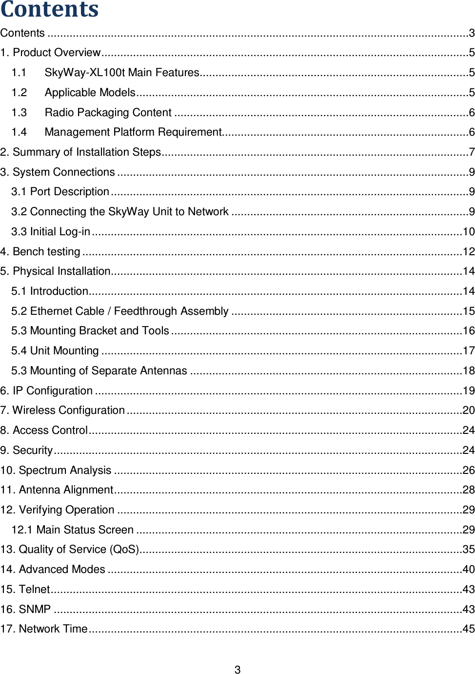


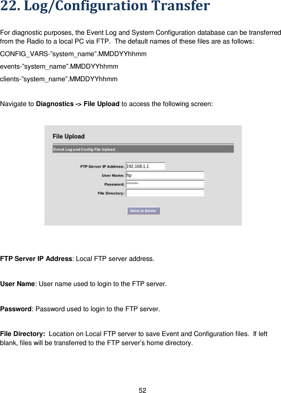
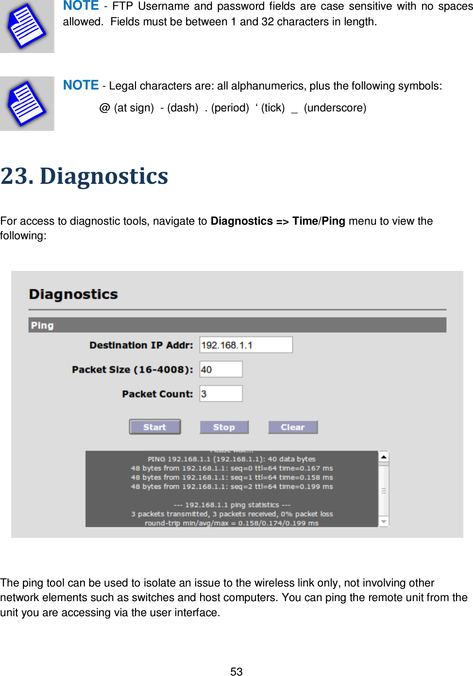
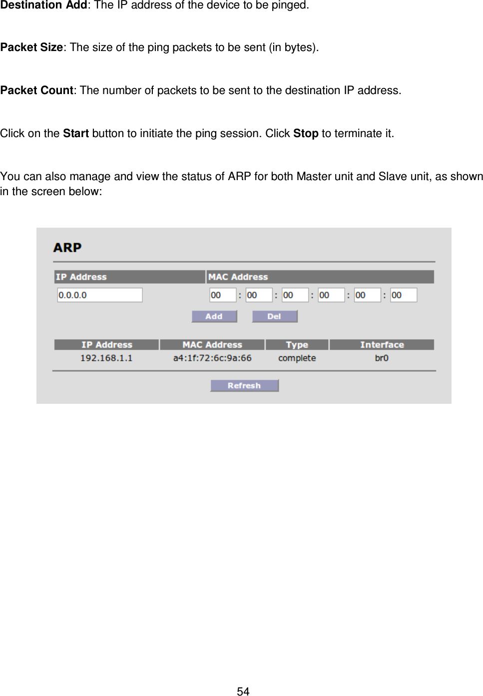
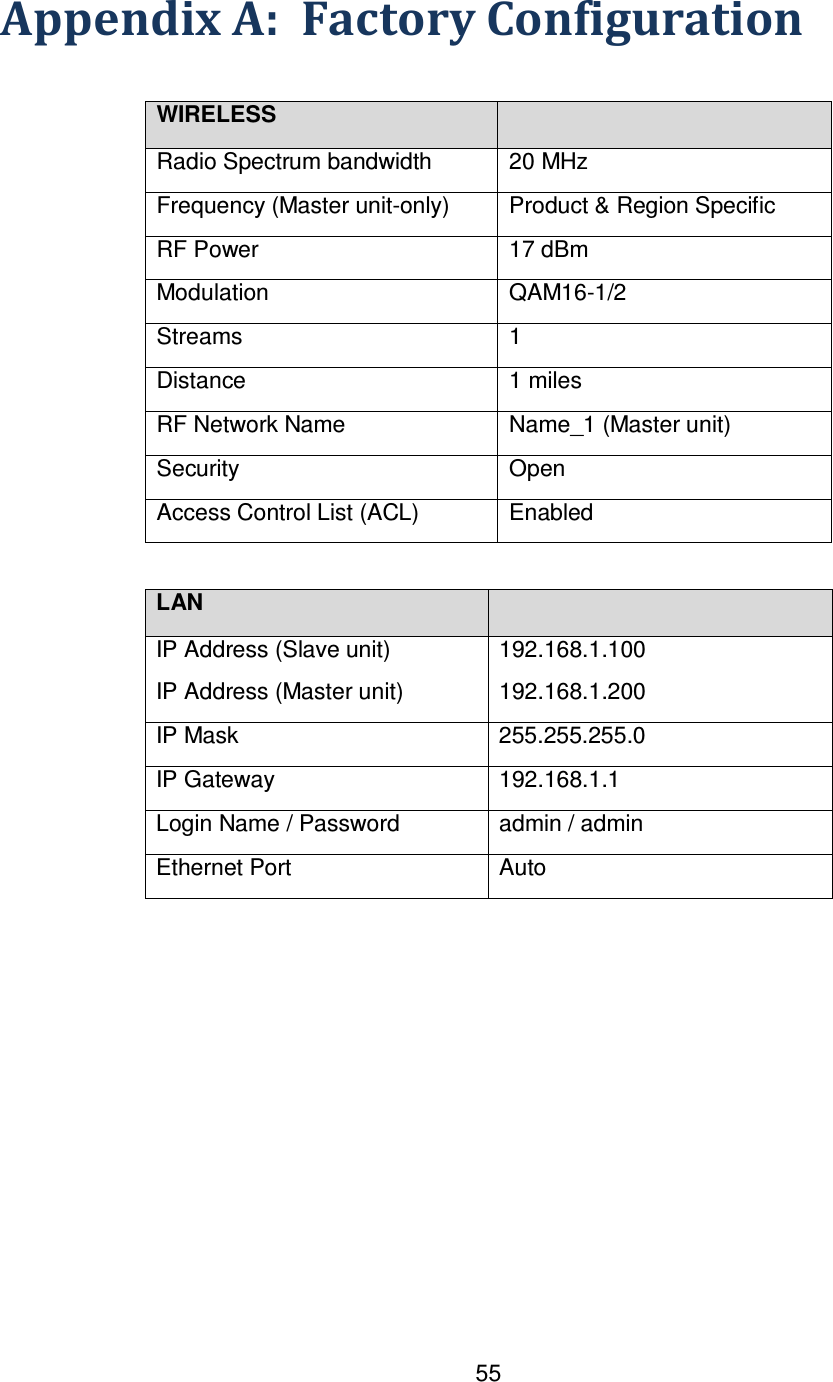
![56 Appendix B: Telnet Commands Command R/W Default Usage Description acl RW enabled acl add [mac] [client-name] acl del [mac] acl show acl [enable | disable] Master unit only Add/Delete/Show entries in the RF access control list. Enable or Disable acl function arp RW arp [OPTION] Options: -a Display (all) hosts -s Set new ARP entry -d Delete a specified entry -v Verbose -n Don't resolve names -i IF Network interface -D Read [hwaddr] from given device -A, -p AF Protocol family Manipulate the system ARP cache audioalign RW 1800 secs set audioalign [duration_secs] show audioalign Set/show Audio Antenna Alignment duration in seconds. Duration 0 disables alignment tone. bridge R show bridge Show Bridge Table bw RW 20 set bw [20 | 40] show bw Set RF bandwidth in MHz chanplan R Varies by Model, Region show chanplan Show channel plan. cfgdiff R cfgdiff [boot] Shows differences between current configuration and default clear W clear Clears all Ethernet & RF Port counters clearevtlog W clearevtlog Clear event log clientcfg R/W clientcfg <mac> [--name <name>] [--dlmod <dlmod>] [--dlstr <dlstr>] [--Show status of and make changes to configured](https://usermanual.wiki/Solectek/59WAN1/User-Guide-2434576-Page-56.png)
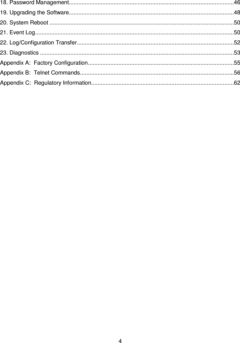
![57 ulmod <ulmod>] [--ulstr <ulstr>] clients clientstat R clientstat <mac> clientstat show - show the status of all connected clients Show status of connected clients connections R show connections Show active connections counters R show counters Show RF statistics date RW date [-u]... [MMDDhhmmYYYY Options: -u Apply the UTC time zone offset to the date Display or set current date default W default Restores system to factory defaults distance RW 16 set distance [miles_or_kilometers] - based on metric setting show distance Set distance in miles or kilometers encrypt RW open set encrypt [open | AES | radius] show encrypt Open: no authentication/encryption AES: PSK authentication / AES encryption Radius: 802.1x authentication / AES encryption ethcfg RW auto set ethcfg [auto-neg | 10baseT-HD | 10baseT-FD | 100baseTx-HD | 100baseTx-FD] show ethcfg Set ethernet speed and duplex exit W Exit Logout from Telnet session freq RW Varies by region set freq [frequency] show freq Set RF frequency in MHz ftppass RW p set ftppass [password] show ftppass Set remote ftp server password ftpuser RW ftp set ftpuser [user] show ftpuser Set remote ftp server username](https://usermanual.wiki/Solectek/59WAN1/User-Guide-2434576-Page-57.png)
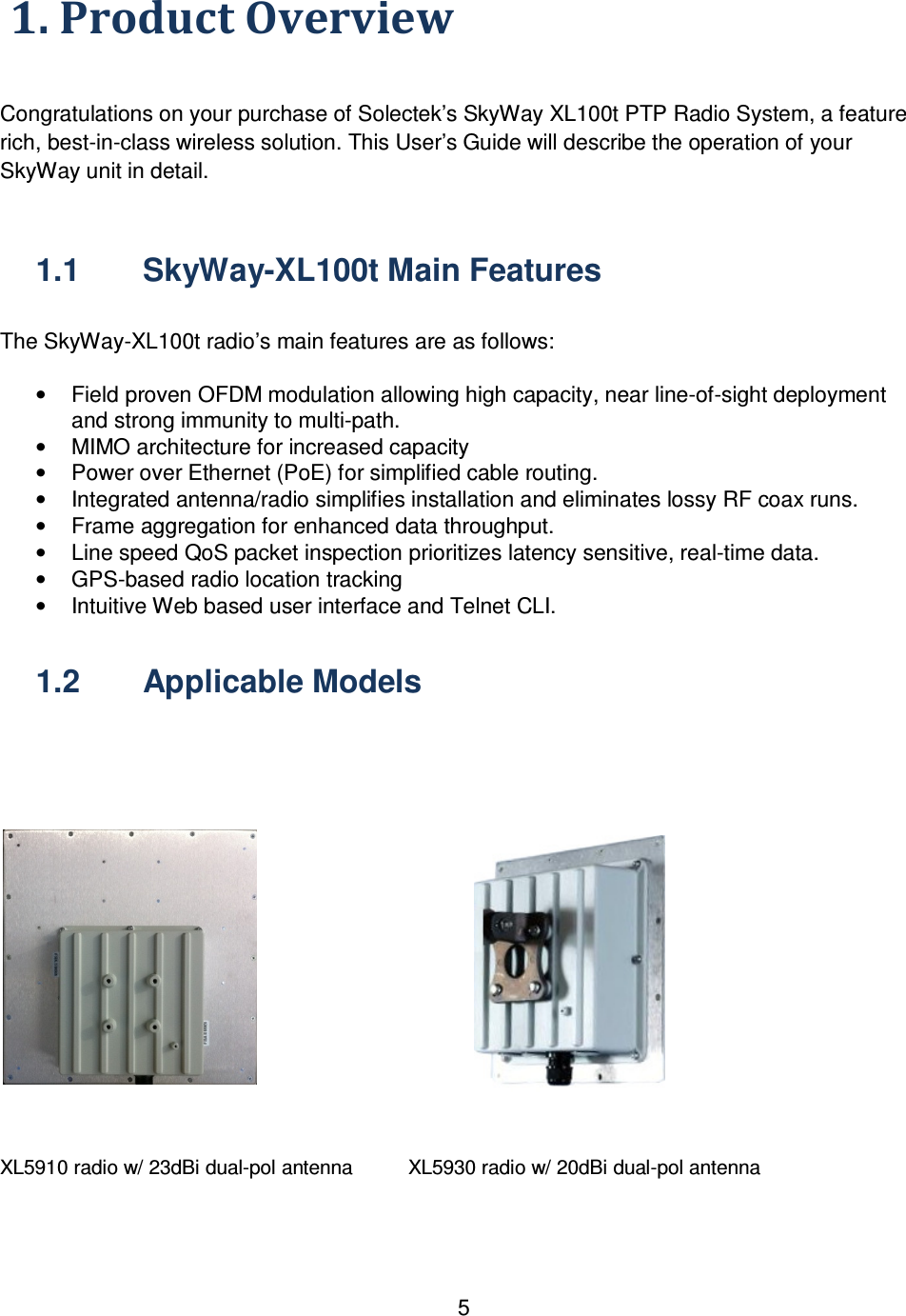
![58 get R Get Get commands gwaddr RW 192.168.1.1 set gwaddr [a.b.c.d] show gwaddr Set default gateway IP address help R help Show commands history R history Show command history ipaddr RW 192.168.1.100 Slave unit 192.168.1.200 Master unit set ipaddr [a.b.c.d] show ipaddr Set IP address ipmask RW 255.255.255.0 set ipmask [a.b.c.d] show ipmask Set IP netmask log R show log Show Event Log logout W logout Logout from Telnet session macaddrs R show macaddrs Show Ethernet and RF MAC addresses metric W miles set metric [miles | kilometers] Set Distance metric mod RW QAM16 ½ show mod set mod [bpsk-1/2 | qpsk-1/2 | qpsk-3/4 | qam16-1/2 | qam16-3/4 | qam64-2/3 | qam64-3/4 | AUTO] Show Current Modulation name RW (blank) set name [name] show name Set system name ntpaddr RW 192.168.1.1 set ntpadd [a.b.c.d] show ntpaddr Set NTP server address password W Factory default: admin Customer default: retains password password [guest] Change admin password or guest password patchlist R show patchlist Show system patches](https://usermanual.wiki/Solectek/59WAN1/User-Guide-2434576-Page-58.png)
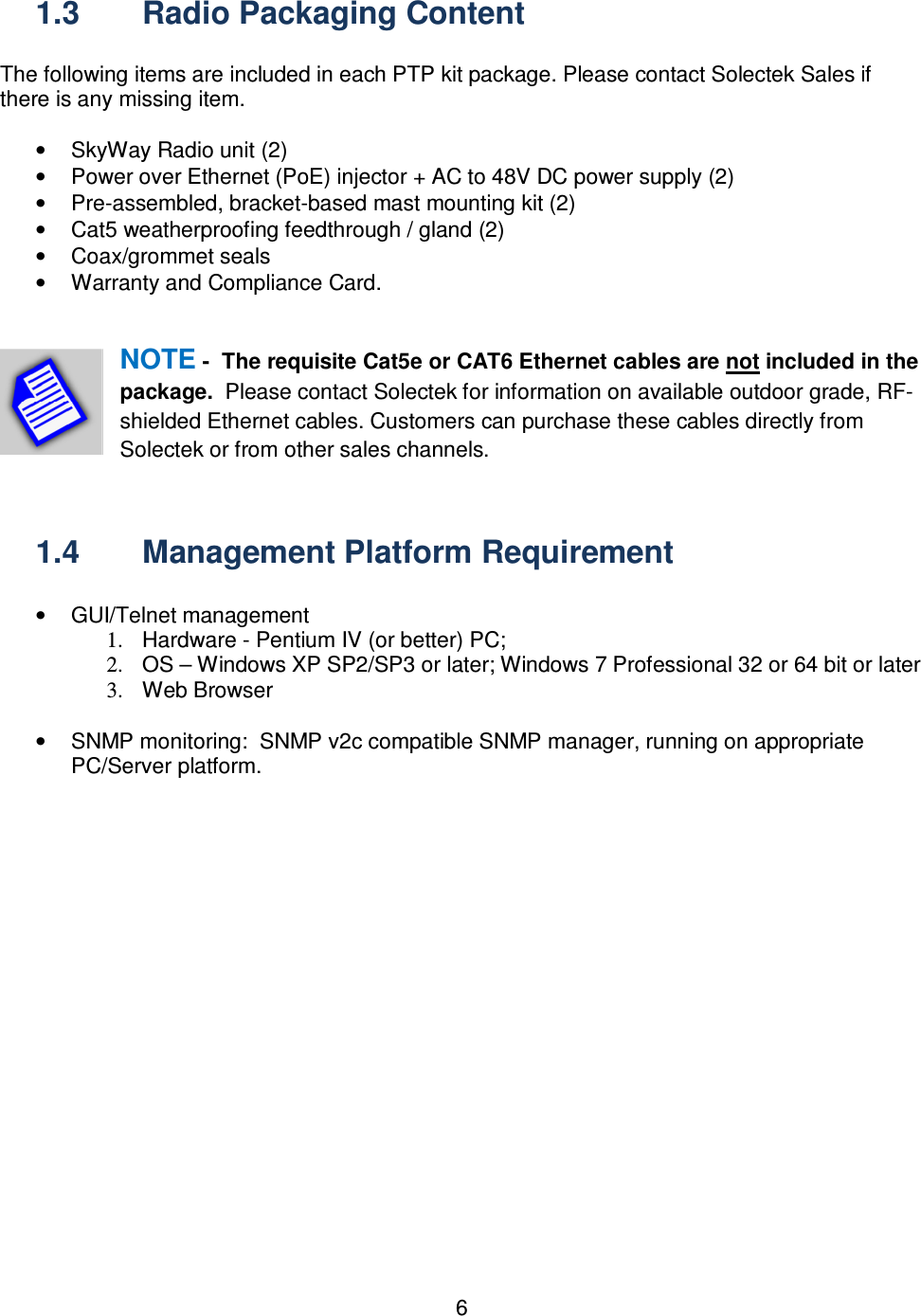
![59 ping W ping [OPTION]... Host Options: -c CNT Send only CNT pings -s SIZE Send SIZE data bytes in packets (default=56) -I iface/IP Use interface or IP address as source -q Quiet, only displays output at start and when finished Test network connectivity power RW 17 set power [rfpower] show power Set RF Transmit power, in dBm product R retains product show product Show product type psk_phrase RW my-big-secret-01 set psk_phrase [phrase] show psk_phrase Set pre-shared key passphrase radius_pass RW abcd1234 set radius_pass [password] show radius_pass Slave unit only Set Radius user password radius_secret RW my-big-secret-01 set radius_secret [secret] show radius_secret Master unit only Set Radius secret radius_server RW 10.20.20.3 set radius_server [server_ipaddr] show radius_server Master unit only. Sets Radius Server IP address radius_timer RW 86400 set radius_timer [period] show radius_timer Master unit only Set Radius reauthentication period, in Seconds radius_user RW wpa1@host.local set radius_user [name] show radius_user Slave unit only Set Radius client user name reboot W reboot Reboot system rfnetname RW NAME_1 set rfnetname [netname] show rfnetname Set RF Network Name rmod RW set rmod [macaddr] [streams] [bpsk-1/2 | qpsk-1/2 | qpsk-3/4 | qam16-1/2 | qam16-3/4 | qam64-2/3 | qam64-3/4| AUTO] Set Remote Modulation/Streams on](https://usermanual.wiki/Solectek/59WAN1/User-Guide-2434576-Page-59.png)
![60 route R show route Show IP route table rssi R show rssi Show Local Recv Signal Strength savecfg W savecfg Save configuration to permanent memory serialnum R show serialnum Show system serial number set R set ? Set ? for commands show R show Show commands snmp RW enabled public – for all strings 192.168.1.1 for trap manager set snmp enable=[yes|no] set snmp [read-community|rc]=[abcdef] set snmp [trap-community|tc]=[abcdef] set snmp [trap-manager|tm]=[a.b.c.d] show snmp Set SNMP configuration parameters status R status Show system status streams RW 1 show streams set streams [1 | 2] Show / Set the number of MIMO data streams. Limited to 1 for Access 50. sysmode RW retains sysmode show sysmode set sysmode [MULTIPOINT_MASTER | MULTIPOINT_SLAVE] Show / Set the MULTIPOINT operating mode tz RW “+00:00” tz [+hh:mm | -hh:mm] Set/Show time zone updatesw W updatesw [options] [swver] Options: -v -verbose output -b -update uboot -k -update kernel -r -update rootfs -h -use http -i -ignore existing configuration -f -force the update Download and install new system software upload W upload config [remotefile] upload syslog [remotefile] Upload files to remote server uptime R uptime Display current system uptime version R version Display current software](https://usermanual.wiki/Solectek/59WAN1/User-Guide-2434576-Page-60.png)
![61 version vlan RW disabled vlan [enable | disable] Enable/Disable management via VLAN vlanid RW 1 set vlanid [vlan id] show vlanid Set VLAN ID for management channel](https://usermanual.wiki/Solectek/59WAN1/User-Guide-2434576-Page-61.png)