Solectek 59WAN1 Broadband PTP and Multipoint Radio Units User Manual XL100t User Guide v1 2x
Solectek Corporation Broadband PTP and Multipoint Radio Units XL100t User Guide v1 2x
Solectek >
revised manual

1
SKYWAY-XL100t 5.9GHz
Point-to-Point (PTP) Wireless Kit
User’s Guide
October, 2014
Rev 1.2

2
Notice
This document contains information that is proprietary to Solectek Corporation.
No part of this publication may be reproduced, modified, or distributed without prior written authorization
of Solectek Corporation.
This document is provided as is, without warranty of any kind.
Registered Trademarks
Solectek® is a registered trademark of Solectek Corporation.
SkyWay® is a registered trademark of Solectek Corporation.
Other trademark names mentioned in this publication are owned by their respective holders.
Statement of Conditions
The information contained in this document is subject to change without notice.
Solectek Corporation shall not be liable for errors contained herein or for incidental or consequential
damage in connection with the furnishing, performance, or use of this document or equipment supplied
with it.
Information to User
Any changes or modifications of equipment not expressly approved by the manufacturer could void the
user’s authority to operate the equipment and the warranty for such equipment.
Disclaimer
In accordance with Solectek’s continuing efforts for improving its products, the information contained in
this document is subject to change without notice. However, Solectek assumes no responsibility or
liability for any errors or inaccuracies that may appear in this document.
Copyright © 2011-2014 by Solectek Corporation. All rights reserved.
Headquarters:
Solectek Corporation
8969 Kenamar Dr, Suite 113
San Diego, CA 92121
858.450.1220 (tel)
www.solectek.com
sales@solectek.com
3
Contents
Contents .....................................................................................................................................3
1. Product Overview ....................................................................................................................5
1.1 SkyWay-XL100t Main Features .....................................................................................5
1.2 Applicable Models .........................................................................................................5
1.3 Radio Packaging Content .............................................................................................6
1.4 Management Platform Requirement..............................................................................6
2. Summary of Installation Steps .................................................................................................7
3. System Connections ...............................................................................................................9
3.1 Port Description .................................................................................................................9
3.2 Connecting the SkyWay Unit to Network ...........................................................................9
3.3 Initial Log-in .....................................................................................................................10
4. Bench testing ........................................................................................................................12
5. Physical Installation ...............................................................................................................14
5.1 Introduction ......................................................................................................................14
5.2 Ethernet Cable / Feedthrough Assembly .........................................................................15
5.3 Mounting Bracket and Tools ............................................................................................16
5.4 Unit Mounting ..................................................................................................................17
5.3 Mounting of Separate Antennas ......................................................................................18
6. IP Configuration ....................................................................................................................19
7. Wireless Configuration ..........................................................................................................20
8. Access Control ......................................................................................................................24
9. Security .................................................................................................................................24
10. Spectrum Analysis ..............................................................................................................26
11. Antenna Alignment ..............................................................................................................28
12. Verifying Operation .............................................................................................................29
12.1 Main Status Screen .......................................................................................................29
13. Quality of Service (QoS)......................................................................................................35
14. Advanced Modes ................................................................................................................40
15. Telnet ..................................................................................................................................43
16. SNMP .................................................................................................................................43
17. Network Time ......................................................................................................................45
4
18. Password Management.......................................................................................................46
19. Upgrading the Software.......................................................................................................48
20. System Reboot ...................................................................................................................50
21. Event Log ............................................................................................................................50
22. Log/Configuration Transfer ..................................................................................................52
23. Diagnostics .........................................................................................................................53
Appendix A: Factory Configuration ...........................................................................................55
Appendix B: Telnet Commands ................................................................................................56
Appendix C: Regulatory Information .........................................................................................62
5
1. Product Overview
Congratulations on your purchase of Solectek’s SkyWay XL100t PTP Radio System, a feature
rich, best-in-class wireless solution. This User’s Guide will describe the operation of your
SkyWay unit in detail.
1.1 SkyWay-XL100t Main Features
The SkyWay-XL100t radio’s main features are as follows:
• Field proven OFDM modulation allowing high capacity, near line-of-sight deployment
and strong immunity to multi-path.
• MIMO architecture for increased capacity
• Power over Ethernet (PoE) for simplified cable routing.
• Integrated antenna/radio simplifies installation and eliminates lossy RF coax runs.
• Frame aggregation for enhanced data throughput.
• Line speed QoS packet inspection prioritizes latency sensitive, real-time data.
• GPS-based radio location tracking
• Intuitive Web based user interface and Telnet CLI.
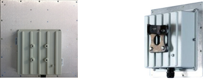
1.2 Applicable Models
XL5910 radio w/ 23dBi dual-pol antenna XL5930 radio w/ 20dBi dual-pol antenna

6
1.3 Radio Packaging Content
The following items are included in each PTP kit package. Please contact Solectek Sales if
there is any missing item.
• SkyWay Radio unit (2)
• Power over Ethernet (PoE) injector + AC to 48V DC power supply (2)
• Pre-assembled, bracket-based mast mounting kit (2)
• Cat5 weatherproofing feedthrough / gland (2)
• Coax/grommet seals
• Warranty and Compliance Card.
NOTE - The requisite Cat5e or CAT6 Ethernet cables are not included in the
package. Please contact Solectek for information on available outdoor grade, RF-
shielded Ethernet cables. Customers can purchase these cables directly from
Solectek or from other sales channels.
1.4 Management Platform Requirement
• GUI/Telnet management
1. Hardware - Pentium IV (or better) PC;
2. OS – Windows XP SP2/SP3 or later; Windows 7 Professional 32 or 64 bit or later
3. Web Browser
• SNMP monitoring: SNMP v2c compatible SNMP manager, running on appropriate
PC/Server platform.

7
2. Summary of Installation Steps
This section summarizes the steps needed to properly configure and install the SkyWay
XL100t Radio. As the background and guidelines for much of the radio installation process
are well covered in many in-depth publications and training classes, only those steps that
uniquely relate to the SkyWay product are covered in this User Guide.
NOTE: Per FCC Part 90.377, this product should NOT be installed at a height not
exceeding 8 meters above the roadway bed surface.
A. System Design
• Requirements analysis
• Site Survey
• RF System Design
• IP Network Design
• Physical/Electrical engineering design
B. Unit Preparation
• Unit connection
• Initial Configuration
• Bench testing
C. Site Preparation
• Physical mounting prep
• Electrical prep
• Cable routing
D. Installation
• Unit Mounting
• Spectrum Analysis
• Antenna alignment
E. Verification
• Link status + metrics
• Ping connectivity
• Performance testing

8
• Reliability monitoring
F. Optimization
• RF channel tuning
• Data rate tuning
• QoS
G. Management + Maintenance
• Upgrades
• Access Methods
• Tools
• Diagnostics
9
3. System Connections
3.1 Port Description
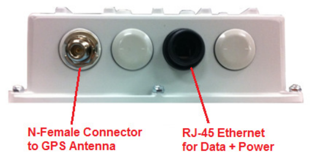
SkyWay-XL100t radio unit has the following access ports:
• (1) 10/100/ Fast Ethernet + Power Connector
• (1) GPS RF port to be connected to a GPS antenna
The RJ45 connector is accessed at the bottom of the unit, through a multi-piece
waterproofing feed-through. If included, the RF Ports are accessed on the bottom of the unit,
which is shown below.
Unit Bottom View – physical interfaces shown
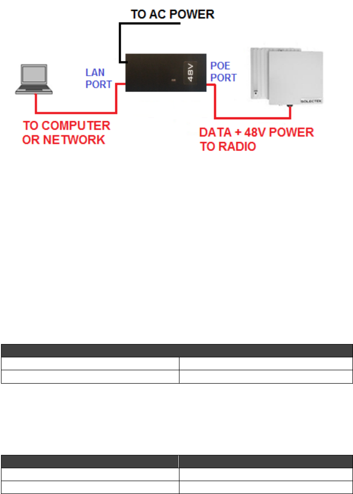
3.2 Connecting the SkyWay Unit to Network
Use the diagram below as a guide to cable your SkyWay test system using a PC or Laptop
and a pair of Cat5e/6 cables. An auto-MDIX feature eliminates the need for cross-over
cables.
10
C
ONNECTION
D
IAGRAM FOR
M
ASTER UNIT AND
S
LAVE
PTP
UNITS
3.3 Initial Log-in
• Open networking properties in your Windows OS. Enter the TCP/IP setup window of
your wired Ethernet adapter properties page. Set the IP addresses to the following
values.
IP Address Setup on your Computer
Ethernet IP Address 192.168.1.1
Subnet Mask 255.255.255.0
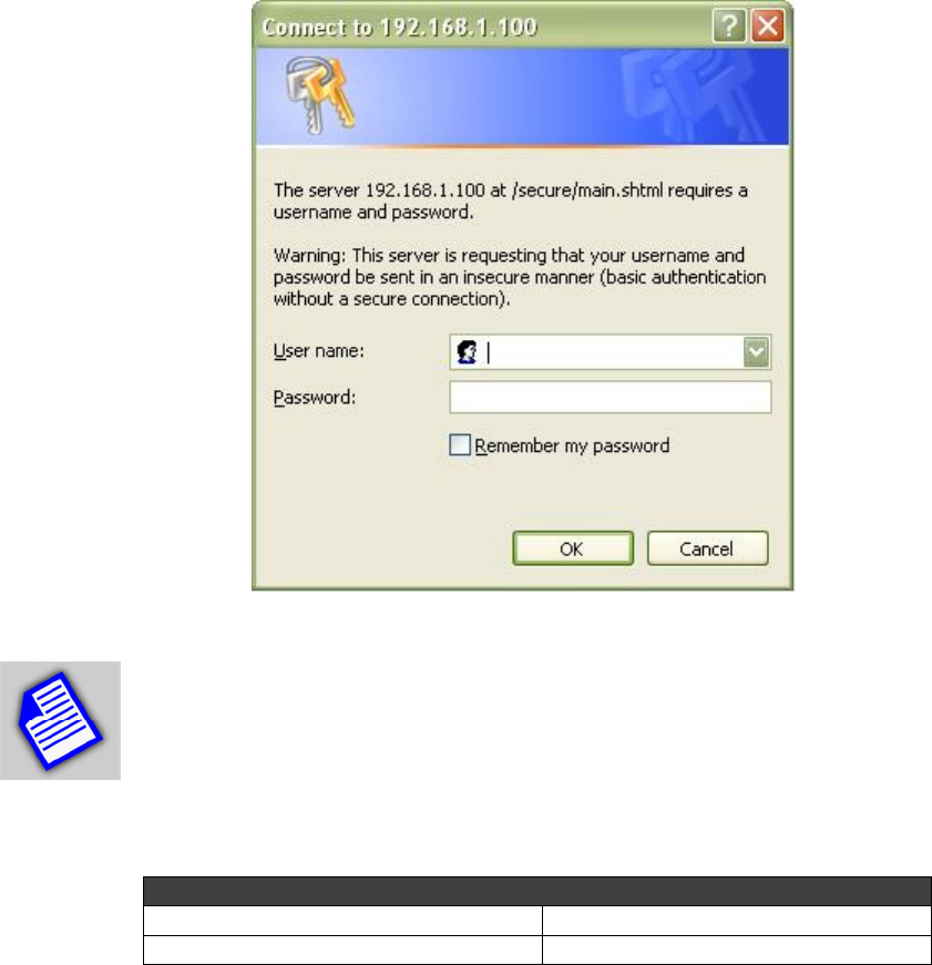
• Open a Web Browser on the Test PC
At the URL line, type in the following:
Type of Unit Default IP Address
Slave Unit 192.168.1.100
Master Unit 192.168.1.200
11
NOTE – Depending on your computer OS, the above screen may look different.
Also, appearance of your GUI will depend on the type and version of your web
browser. Please contact Solectek sales and support for detailed information.
• The access username is admin and the default password is admin.
Default Radio Log-in Info
User Name admin
Password admin
• Click OK on the above Windows screen and the Main Status screen will be displayed, as
shown below (Master unit version):

12
4. Bench testing
Before mounting units into their final location, it is recommended that the system be bench
tested to verify basic operation. The following bench test steps are suggested:
Setup. Each radio should be connected and configured per the previous Sections, with a laptop
or PC connected to each radio directly (or through a hub/switch).

13
WARNING – DO NOT connect two radios to the same switch or a loop will be
created, which will create a failure of the
NOTE – Make sure that Access Control MAC addresses are correct and that
units share the same bandwidth, data rate and security settings. Access Control
List (ACL) is enabled as a factory default setting.
It is also important to have identified and prepared the antenna, RF coax and Cat5 solutions that
will be used in the intended application.
Positioning. It is important to remember that the SkyWay radio and antenna system generate
and transmit a great deal of RF power. During bench testing, antennas should not be pointed
directly at each other. Rather, establish a position so there is approximately 180 degrees
angular separation and 6 to 10 feet between units. Fine tune the antenna position so that the
Local RSSI is between -30 and -60 dBm.
Testing. If the system has been properly configured, the radios will begin communicating
immediately. The following steps are recommended to verify operation:
• Link State. On the Main Status screen, verify that the RF Link State is Green
(connected).
• Local ping. From each laptop/PC be sure a ping to the local radio is successful.
• Link ping. Now ping from one laptop/PC to the other laptop/PC. This will verify the end-
to-end link.
• Traffic test. Using IPERF or equivalent utility, verify traffic can be passed successfully
across the link.
NOTE - Keep in mind that the SkyWay-XL100t data rates will stress the
performance of the PC hardware, operating system and IP stack. To ensure that
this test equipment is not a performance bottleneck, pre-testing PCs, by connecting
them directly to each other, is strongly recommended.

14
NOTE -Using a file transfer to a shared volume or an FTP session on a typical
Windows/Intel machine is not adequate to accurately measure throughput.
NOTE - Units bench tested in an indoor configuration should not be
expected to deliver full rated throughput. Benchmarking is typically
performed after a system is deployed.
WARNING – When it is not in use, the GPS port of the GPS-ready Master unit
must be sealed to prevent water intrusion. The port is factory configured with a
sealing pin. Please leave it in place until you are ready to connect to a GPS
controller.
5. Physical Installation
5.1 Introduction
Your SkyWay radio is designed with a mounting system with two degrees of freedom. The radio
can be mast, tower, pole or wall mounted using the appropriate hardware. After determining the
best location for your radio, installation can begin.
To mount a SkyWay-XL100t radio unit, both the mast mounting kit and Ethernet cable
feedthrough need to be correctly assembled. The recommended approach consists of 3 or 4
steps, detailed in the following sections:
• Ethernet cable / feedthrough assembly
• Bracket preparation
• Mounting
• Antenna mounting (for connectorized units, only)
With the exception of the CAT5 cable, all parts and hardware described in the following sections
are included with your SkyWay radio.
15
5.2 Ethernet Cable / Feedthrough Assembly
Only a single Ethernet cable is needed to connect the SkyWay radio to the indoor PoE Injector.
Since the cable is exposed to the outdoor elements (heat, moisture, and UV light), only outdoor
rated, shielded Cat5 Ethernet cable should be used. To ensure all-weather operation, the
weatherproofing cable feedthrough (also known as grommet or gland) must be properly
assembled onto the Ethernet cable and radio.
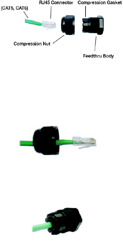
The following diagram depicts each of the feed-through parts:
Assembly Steps:
1. Remove the Compression Nut and slip it over the Ethernet CAT5 cable as shown below.
2. Feed the Ethernet CAT5 Cable through the Feedthrough Body (pre-installed on the
enclosure at the factory) and insert the RJ-45 connector to the female connector inside the
enclosure.
3. Install the Compression Nut and hand tighten until the cable resists slipping when gently
pushed or pulled. Lightly wrench-tighten, being careful not to overtorque the Compression
Nut.
16
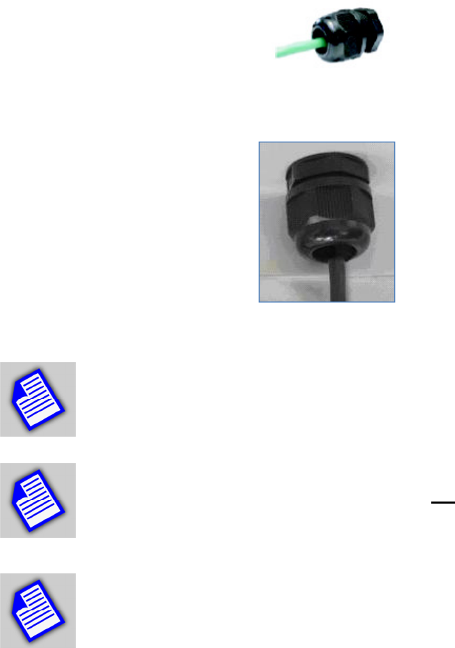
The unit with properly installed feedthrough appears as follows:
NOTE - Removal of the RJ45 plug from the radio requires a tool such as a thin
screwdriver, or opened paperclip. Care must be taken not to damage the
Feedthrough Body or RJ45 plug.
NOTE - The total combined length of the Ethernet cables between the radio and
your network access device (hub/switch/PC) must not exceed 300 feet.
NOTE - Once mounted in a permanent location, additional weatherproofing tape
(included) should be applied around the assembled fitting to further enhance
durability.
5.3 Mounting Bracket and Tools
The following figure shows all components of the mounting kit.
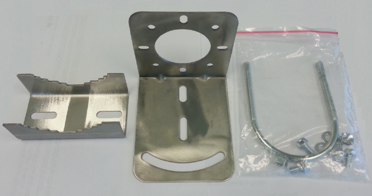
17
The installation steps will be shown in the next section.
Tools necessary for tightening bolts and nuts are:
• 10mm wrench for bolts to fasten the L-bracket to the radio enclosure
• 13mm wrench for nuts to tighten U-bolt nuts.
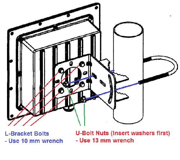
5.4 Unit Mounting
The final installation step involves mounting your SkyWay radio to an outdoor mast.
Refer to the following diagram to perform the installation steps:
• Fasten the L-bracket on the back of the radio enclosure. The hole patterns are
symmetric and you can rotate the enclosure by 90 degrees before installing the L-
bracket for establishing the radio link with horizontal polarization.
• Using the step bracket and U-bolt, fasten the L-bracket to the mast.
18
Azimuth alignment – Rotate the enclosure assembly in the horizontal direction
Vertical alignment - The L-bracket has a curved groove which can be used to tilt the enclosure
up or down.
Once the alignment is complete, tighten the bolts and nuts firmly.
5.3 Mounting of Separate Antennas
Tower or mast mounting of the antenna should proceed according to the antenna
manufacturer’s guidelines.
For interfacing to the Solectek radio, the following should be considered:
• To minimize loss, only short lengths of high quality, LMR-400 (or equivalent) RF coax
cables should be used.
19
• For Master unit radios, there are no requirements to connect specific radio ports to
specific polarizations on the antenna. Solectek’s MIMO system will auto-adjust to
accommodate the chosen configuration.
Weatherproofing Ethernet and/or antenna connections is essential. This process prevents water
from entering the chassis or cables through the connectors.
In order to provide an adequate seal, it is advisable to apply three wrappings:
1. electrical tape
2. sealant (such as the butyl mastic which is provided with the product)
3. electrical tape
The first wrapping of tape should be a single layer, followed by a generous wrap of butyl
mastic. Finally, apply two layers of electrical tape, completely covering the mastic layer. Wrap
the last layer of tape such that water is always directed down and away from connections.
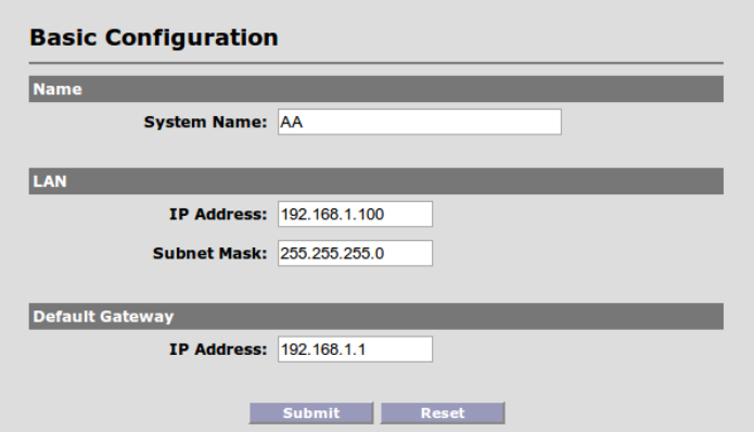
6. IP Configuration
Navigate to Configuration -> Basic to access the Basic Configuration screen. The top one is
for the Master unit and the bottom one is for the Slave unit.
20
• System Name This is an optional description of the unit used to simplify the
identification of a particular radio in the wireless network. This parameter is not related
to the identification of the unit on your wired local area network. For security purposes,
the System Name is not broadcast across the RF link. Name can be up to 32 characters
long, and consist of all alphanumerics, plus the following symbols: @ (at sign), -
(dash), .(period), ‘ (tick), _ (underscore). Name may not include spaces.
LAN /Default Gateway Configuration
• IP Address: IP address of the local unit.
• Subnet Mask: Subnet mask of the local unit.
• Default Gateway: Default gateway for the local unit.
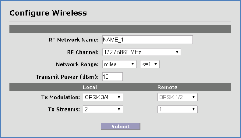
7. Wireless Configuration
Navigate to Configuration -> Wireless to access the Wireless Configuration screen. This
screen is for initial parameter settings only (for Slave unit configuration, go to Configuration ->
Clients). The top screen shown below is for the Master unit and the bottom one is for the Slave
unit:

21
Bandwidth Allows selection of the bandwidth (BW), in MHz, of the RF network. The standard
channel is 10 MHz and there are two channels with 20MHz bandwidth.
Both Master and Slave units must be configured with the same Bandwidth setting.
Frequency Allows selection of the center frequency of the RF link, based on the model
purchased, region of operation and operating bandwidth. The Frequency setting is available on
the Master unit only. The slave unit will follow that of the Master unit.
A sample frequency list for the US FCC ITS band, is as follows:
Channel Number and BW Frequency Center Application Product
# 172 – 10MHz 5860 MHz XL5910 and XL5930
# 174 – 10MHz 5870 MHz XL5910 and XL5930
# 176 – 10MHz 5880 MHz XL5910 and XL5930
# 178 – 10MHz 5890 MHz XL5910 and XL5930
# 180 – 10MHz 5900 MHz XL5930 Only
# 182 – 10MHz 5910 MHz XL5930 Only
# 184 – 10MHz 5920 MHz XL5910 and XL5930
# 175 – 20MHz 5875 MHz XL5930 Only
# 181 – 20MHz 5905 MHz XL5930 Only
NOTE – Due to the FCC EIRP regulations, XL5910 PTP kits with 23 dBi antenna
cannot be used in certain channels as indicated above (#180, 182, 175, and 181).
Link Distance Should be set to the link distance, rounded up to the nearest mile or km. This
parameter is used to optimize the performance across long distance links, accounting for the
time of flight of packets from one side to the other.
RF Network Name The wireless network name assigned to this PTP kit only.

22
NOTE - The RF Network Name should be changed from the default settings, and
each PTP link should use a unique RF Network Name.
NOTE - RF Network Name can be up to 32 characters long, and consist of all
alphanumerics, plus the following symbols: @ (at sign) - (dash) . (period) ‘ (tick) _
(underscore). RF Network Name may not include spaces.
Transmit Power This parameter sets the RF output power of the radio. Increasing this value
will extend the range of the PTP system. However, the maximum available power is limited by
the chosen RF modulation and the regulatory entities in each country. The available values are
6, 7, 8, 9 and 10 dBm
Modulation Used to establish the transmit modulation and FEC rate of the OFDM radio. The
higher the modulation setting (or “density”), the higher the link data rate, but the lower the
receive sensitivity.
From lowest to highest data rates, the available modulation/FEC settings are:
• BPSK- ½
• QPSK- ½
• QPSK- ¾
• QAM16- ½
• QAM16- ¾
• QAM64- ⅔
• QAM64- ¾
• AUTO
From the above screen on the Master unit, Tx/Rx modulations for each client can be set
individually. The values can be a specific modulation type or AUTO, using the ACM feature
shown below.
Adaptive Coding and Modulation (ACM) The AUTO setting above will enable the ACM
function in the network. This feature allows the system to determine the best TX modulation and
MIMO settings based on current RF conditions. At power-up (or reset), the ACM function will
begin operation at the most robust modulation and MIMO settings (BPSK-1/2, 1 stream). If link
conditions warrant, higher order settings will be tested and selected for use.
23
The ACM function operates continuously, i.e. – if RF link conditions change, then the
modulation and MIMO settings will respond in order to maximize link capability without
compromising reliability.
The system relies upon user traffic to determine the optimal modulation settings. When ACM is
enabled, user traffic must be available in order to bring link performance up to its maximum
capability.
ACM is a feature that is enabled on a per-radio basis. It is not necessary for both radios to
share the same state ACM enable/disable configuration.
ACM seeks to optimize the TX modulation of the radio on which it has been enabled. Since RF
conditions may not be the same on either side of the link, due to impairments such as
interference, the system may not select the same TX modulation/MIMO settings for each side.
The RF power settings will not be adjusted by the ACM system.
If the RF power is set above one of the power/modulation thresholds listed in the Transmit
Power section, the ACM system will not likely reach higher order modulations. For example, if
the radio power is set to 23dBm, then the ACM will not be capable of achieving QAM16 or
QAM64 operation.
Tx Streams The power of MIMO technology rests on the ability to define the number of data
streams that are carried across the two (2) RF links. At all times, the XL100t radios utilize a 2x2
dual-chain MIMO format where 2 RF transmit and 2 RF receive chains are enabled and active.
However, these dual chains can be used to carry 1 or 2 data streams. XL100t systems are fixed
to 1 stream operation only.
In a 2 stream configuration, unique data is carried across each RF chain, greatly increasing the
amount of data capacity over a non-MIMO system. The 100 Mbps capability of the product
requires that 2 streams operation be configured.
In contrast, when increased link robustness and noise immunity is desired, MIMO can be used
in a 1 stream configuration. In this scenario, the same information is carried across both RF
chains, increasing the reliability of reception.
It is recommended that both Master unit and Slave unit share the same Modulation and Stream
settings.
24
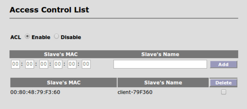
8. Access Control
In order to match up with the Slave unit, the Master unit must be configured properly for the
Slave unit. Navigate to Configuration -> ACL on the Master unit to access the following screen:
Access Control List (ACL) – enabling the ACL means that the Master unit only accepts Slave
unit whose MAC addresses are registered at the Master unit. Disabling the ACL allows any
Slave unit that operates with the same RF parameters as the Master unit.
In order to add a new Slave unit, enter the MAC address and the client name (name of your
choice) and click the ADD button.
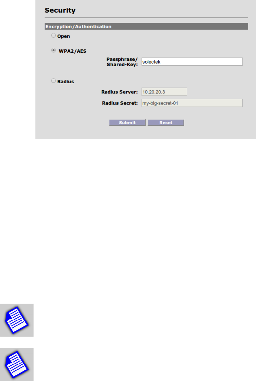
9. Security
Navigate to Configuration -> Security to access the Security Configuration screen a shown
below.
25
Three security options are available: Open, AES and Radius. All units on a wireless network
must share the same security settings.
Open: Removes all encryption and formal authentication methods. Note that even with the
“Open” setting, there is still a MAC address based Access Control system which provides a
basic level of security. (See the section on Access Control)
WPA2/AES: Provides 128-bit WPA2/AES data encryption with passphrase/shared-key based
authentication.
Radius: This option combines AES data encryption with Radius/802.1x authentication capability,
compatible with MS-CHAPv2/EAP authentication servers.
NOTE
- AES passphrase and Radius identity / secret / password fields are case
sensitive with no spaces allowed. Passphrase must be between 8 and 63
characters in length. The shared-key must be 64 Hex digits.
NOTE
- Radius identity must contain an ‘@’ symbol, and is typically in email
address format.

26
10. Spectrum Analysis
Once the radio has been mounted in its intended location, an embedded RF spectrum analysis
tool can be used to survey the site and to aid with the initial channel selection process.
Prior to enabling a spectrum analysis session, ensure that the units are mounted at the desired
location and aligned in the general direction of the target radio.
NOTE - If a noise and interference only analysis is desired, do not turn on the
remote unit during the spectrum analysis, as the presence of the remote unit will
affect the sweep data.
NOTE - Enabling a spectrum sweep will disable RF traffic until (a) the scan is
manually stopped, (b) the run time set by the user runs out or (c) the 5 minute test
period is complete. The 5 minute test period is based the US channel plan (FCC).
International channel plans with larger number of channels may take longer time.
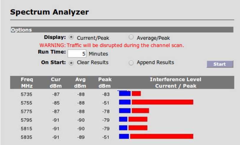
Click Installation -> Spectrum Analysis on the Toolbar to access the Spectrum Analysis
screen:
27
In the example screen shown above, the scan shows high levels of interference at 5755 and
5835 MHz, and these channels would be unsuitable choices for satisfactory performance. While
any of the remaining 20 MHz channels would be preferable, the channel centered on 5795 is a
better candidate, as it is further from the strongest interferers.
There are two display options (Current/Peak and Average/Peak) to assist with analysis.
Alternating between the two modes will not erase the collected data.
There are also two scan modes. The first, Clear Results, removes all historical scan data and
reports only information gathered during the current scan. Alternatively Append Results can be
selected if displaying aggregated results across multiple scans is desired.
To begin spectrum analysis, click Start button. The unit will scan through the available channels
and display the results on the bottom of the screen. Numerical results, measured in absolute
power (dBm) will indicate the interference and noise levels based on received signals from each
channel. The blue bar indicates either the current or average power level (depending on mode
selected) and the red bar indicates peak power received during the test interval.
After 5 minutes of scanning, the radio will automatically disable the scan and return to normal
operation when the configured Run Time expires. A scan can be terminated sooner by clicking
the Stop button on radios with local Ethernet access.

28
11. Antenna Alignment
SkyWay XL100t contains several tools to aid with the antenna alignment process that is
essential for Slave units.
Audible Alignment: The radio produces an audible tone allowing antenna alignment without
the need for additional monitoring hardware.
CAUTION - A ping, or other network traffic is needed to ensure reliable operation
of the alignment feature, in which case the Activity indicated will be in a green state.
If no network traffic is detected, the Activity indicator will be in a red state.
The pulsed tone will begin once an RF link has been established, regardless of quality. It is
useful to reduce the RF modulation setting to its lowest value (BPSK) during the antenna
alignment procedure to maximize the system’s link capture envelope/angle.
The audible repetition rate will increase as RSSI improves; a higher value will cause a faster
rate. To assist with both coarse and fine tuning, the rate is NOT a simple function of RSSI value.
Rather, the rate will continue to increase as long as adjustments deliver an improved RSSI. As
soon as any degradation (alignment ‘overshoot’) is detected, the rate quickly falls, regardless of
the amount of reduction. Thus, the system is useful for both coarse and fine tuning of the
antenna position.
To ensure the system will deliver adequate link reliability, it is recommended that the operator
verify the numerical RSSI following antenna alignment.
The audible function is enabled for the first 30 minutes of operation following a power cycle. If
desired, the audible function can be manually disabled using the telnet command: set
audioalign 0 or via the Alignment Page (below).
Regardless of whether the audible function is enabled or disabled, the unit will emit a short
audible tone upon initial power-up.
Alignment Page: An alternative tool to assist with antenna alignment is the Antenna Alignment
page. Navigate to Installation -> Antenna Alignment to display the following page:
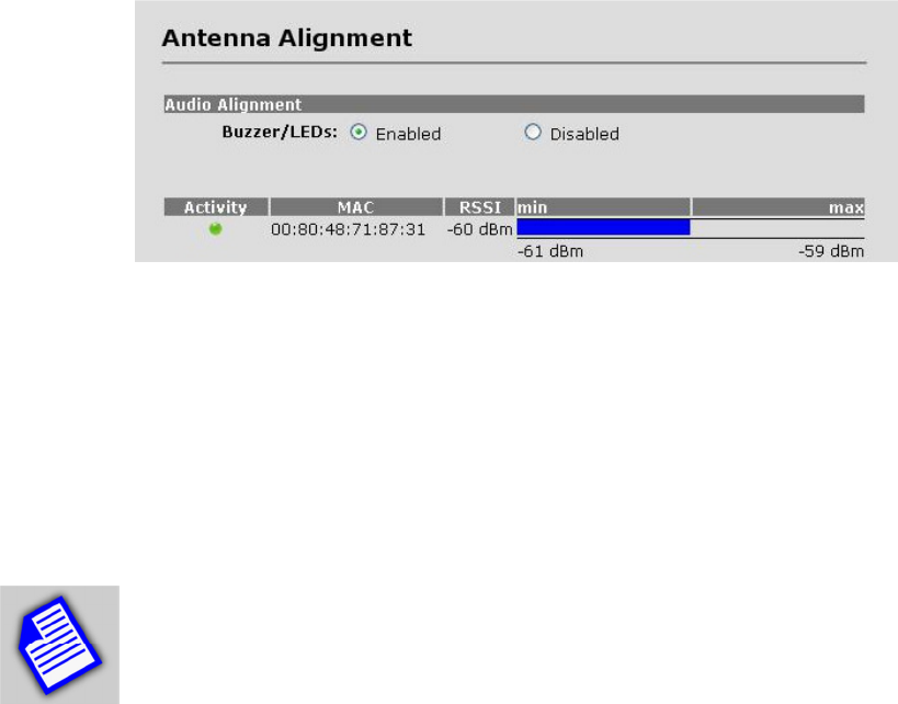
29
On this page is a dynamic display of the RF link state and local RSSI, in both numerical and
graphical format. In addition to displaying current RSSI, the bar graph format has an auto-scale
function which tracks the minimum and maximum achieved RSSI values since power-up.
NOTE – Fluctuations in RSSI values up to ±2 dB should be expected. This should
be considered normal behavior of the radio.
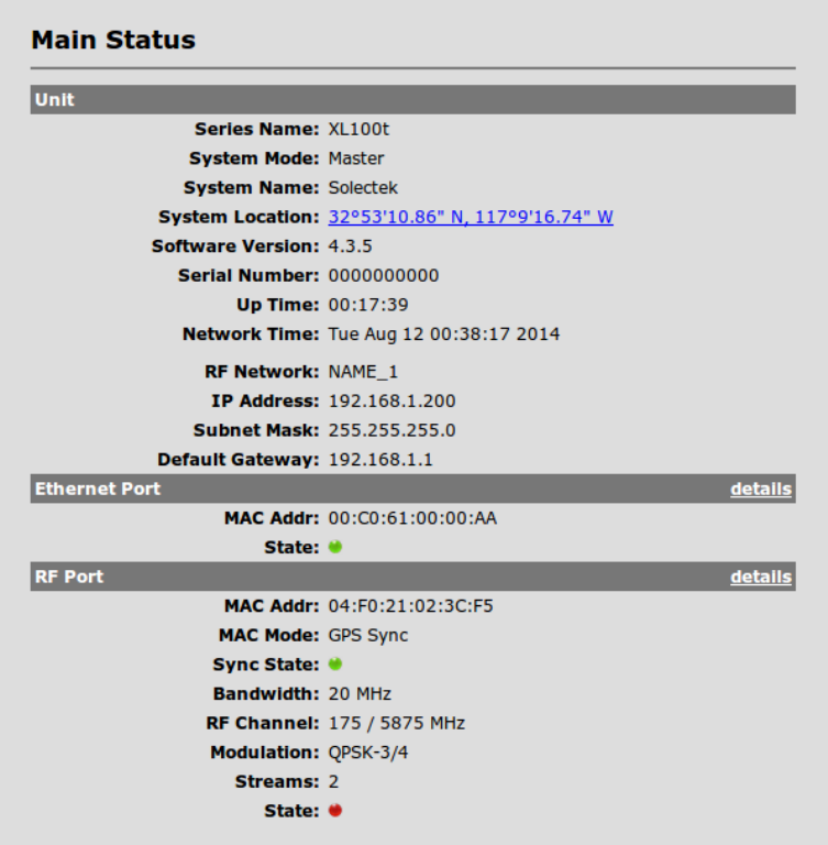
12. Verifying Operation
12.1 Main Status Screen
The basic status can be viewed in the Main Status screen:
30
This screen updates periodically and thus displays current field values. Navigate to the
Configuration screen if setting changes are necessary.
There are several noteworthy items:
Software Version The currently installed, operating image version.
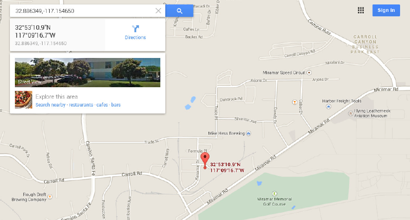
System Location Each radio unit included a built-in GPS module and the administrator can
locate the unit’s location real-time for asset tracking purposes. The current GPS coordinates are
displayed here and clicking the hyperlink will open up a Google map in another window such as
the following:
31
Up Time The elapsed time that the unit has been running since the last reboot or power cycle.
Ethernet Port – details of the Ethernet port status can be viewed by clicking the details on the
right side of the screen. The actual screen is shown in Section C below. The Ethernet Port MAC
address is shown for diagnostics purposes, but has no effect on the Master unit to client
wireless connection.
RF Port – The RF Port MAC address is what is used by access control and thus must be
entered into the access control list at the Master unit.
State (RF Port) The link state has two values.
Green – An RF link has been established
Red – An RF link is NOT established.
Clicking on the details button on the Ethernet port and RF port will show the following screen.
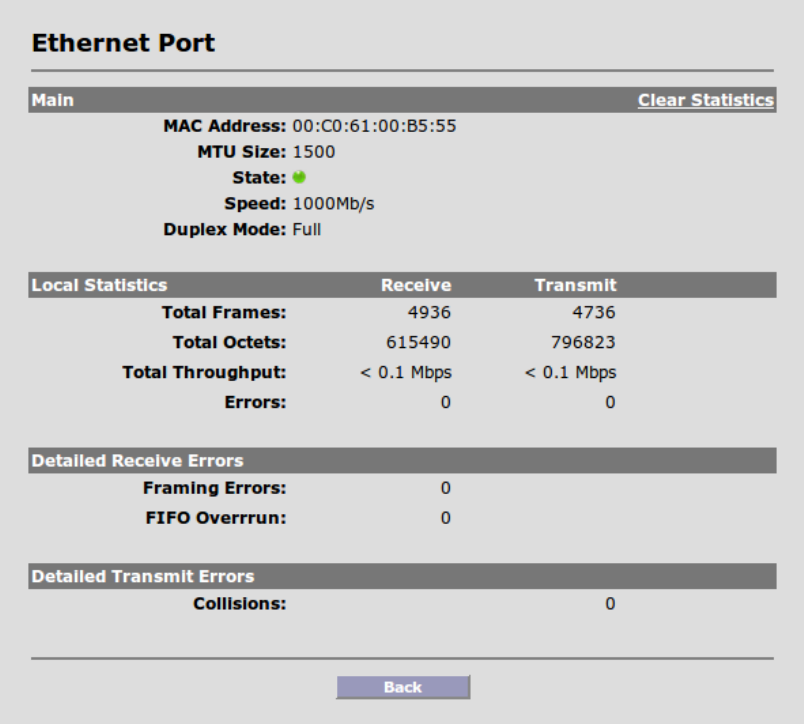
32
MTU Size The maximum datagram size that the system is able to transmit. Note that this refers
to Ethernet payload not total Ethernet frame size. This parameter is not user configurable.
State: There are two states, Green – Port Up. Red – Port Down.
Total Frames: Total number of frames received and transmitted by the Ethernet port.
Total Octets: Total number of octets (bytes) received and transmitted by the Ethernet port.
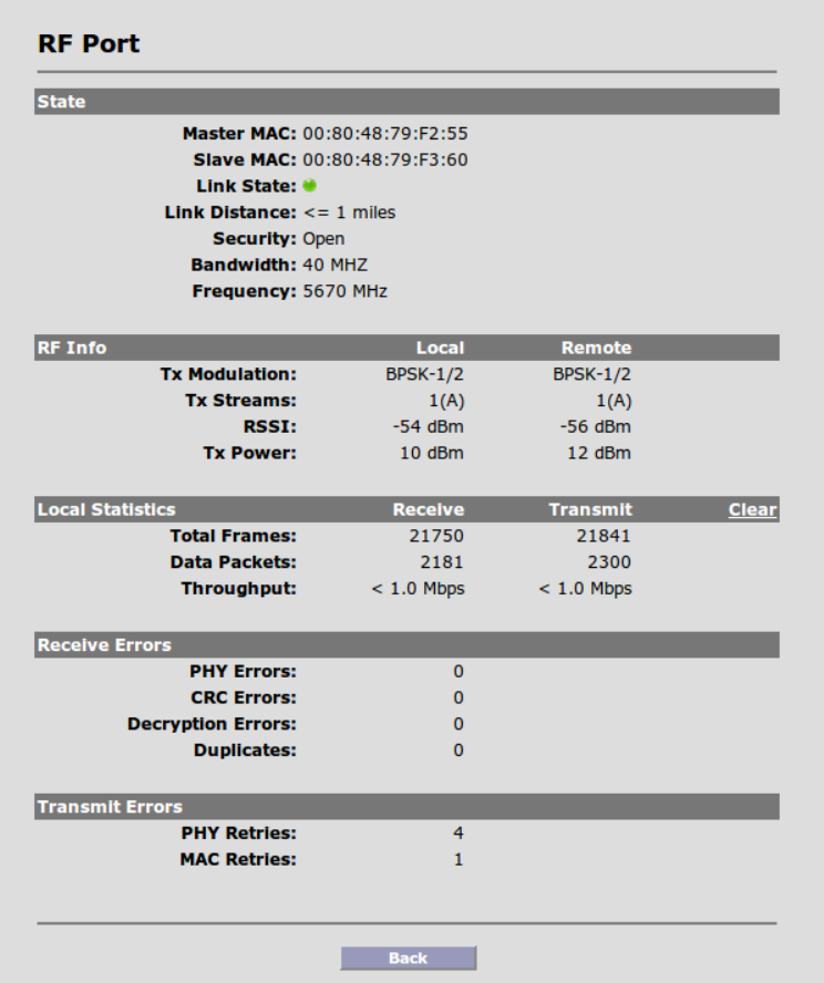
The RF Port (navigate to the details button on the Main Status screen next to each client’s
description) also has its own detailed screen:
33
RF Info – This section shows values seen from local and remote unit. Values are displayed
from its own perspective. Local RSSI, for example, means the RSSI read from the local receiver.
Tx Streams – This indicates whether the unit is being operated with 1 data stream or 2 data
streams over the RF channel. The ACM operation is indicated by the designation of an ‘A’ in
parenthesis. Fixed operation is indicated by an ‘F.’
Local Statistics – These are values experienced by the local unit. Receive Column details
values at the local unit receiver and Transmit Column details values at the local unit transmitter.

34
Throughput – Please note that the throughput value displayed here do not refer to the radio
link capacity. Rather, it refers to the instantaneous throughput over a short time period
measured by the unit. The value here is meaningful for estimating the traffic amount if such
traffic can be sustained over some time period. Due to framing overhead, actual IP throughput
will be less.
Total Frames: Total number of aggregated RF data frames received and sent by the unit.
NOTE – Total Frames number from RF port number should not be expected to
match the Ethernet frames count. Packet framing, aggregation and QoS operations
will all affect the manner in which data is transported from Ethernet to RF port.
Data Packets: Total number of data packets prior to aggregation, on the transmit side, and
following de-aggregation, on the receive side.
Receive Errors: Total number of Errored Frames received by the local unit.
NOTE - When diagnosing link problems, it’s useful to clear the RF statistics and
allow 5-20 minutes of new data to accumulate. This will provide an accurate
picture of the current link conditions. On occasion, it may be useful to sample a
longer time period, up to 24 hours in some cases, as the influence of external
interference sources can vary across time due to usage patterns. In many situations, some
amount of errors may be expected and unavoidable.
NOTE - RF Frames which are significantly damaged can not be accurately
attributed to a paired radio and will not be counted towards receiver errors.
NOTE - Some amount of error is expected and unavoidable in most wireless link.
Retransmissions will be transparently handled by the radios and by any TCP-IP
hosts connected to the link. For evaluating link quality, the figure of interest is the
Frame Error Rate, which can be obtained by dividing the number of errored frames
by the total number of frames.
In general, a Frame Error Rate less than 10% will have little or no noticeable effect on
throughput.
35
Transmit Errors: Total number of frames transmitted by the local radio that were not
successfully acknowledged by the remote radio.
Errors of this type can be attributed to two causes: (a) Data packet not received by remote
radio, or (b) Acknowledgement packet from remote radio not received by local radio.
NOTE -
Because the SkyWay XL100t radio is a TDD system and uses the same
frequency for both transmit and receive, it is often instructive to compare RX and
TX error counts on both sides of the link so that RF impairments can be isolated to
the appropriate link direction and radio.
For example, if Radio A has a large number of TX errors and Radio B has a large number of RX
errors, one could conclude that the RF link from A => B was impaired. Sources of potential
interference at Radio B could then been investigated.
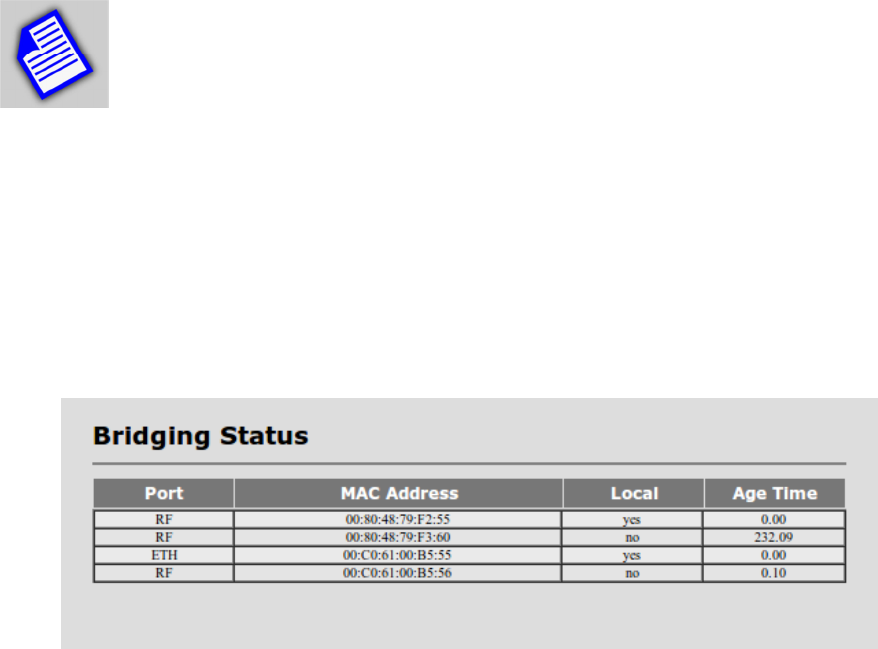
Bridging Status of the RF and Ethernet ports can be monitored by going to Status->Bridging:
13. Quality of Service (QoS)
Introduction
The XL100t QoS model is based on the Wireless Multimedia Extensions (WME). This is also
known as Wi-Fi Multimedia (WMM) and is a Wi-Fi Alliance inter-operability certification, derived
from the IEEE 802.11e standard. It provides basic Quality of service (QoS) features to IEEE
36
802.11 networks. WMM prioritizes traffic according to four Access Categories (AC) - voice,
video, best effort, and background. However, it does not provide guaranteed throughput.
QoS Implementation in Access
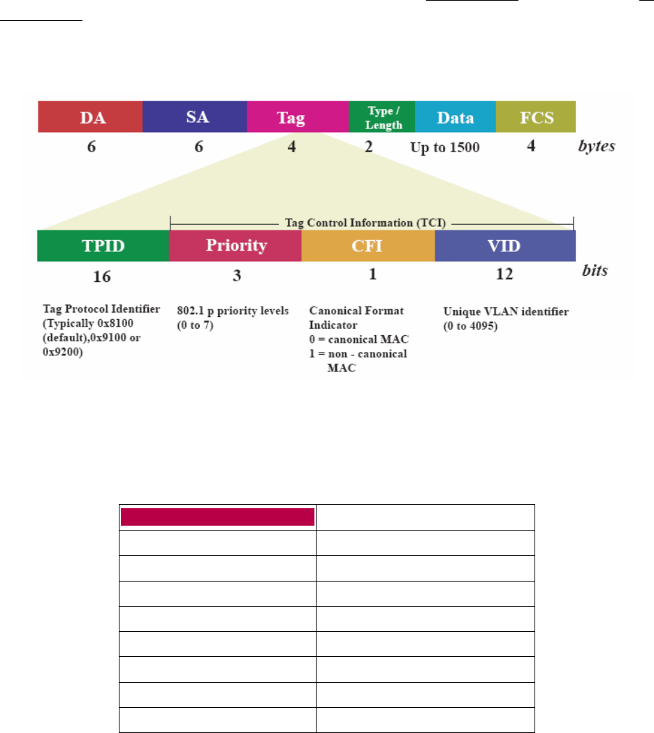
The software driver basically classifies the PDU's based on VLAN priority (if present) and IP
Precedence bits. The first classification is with VLAN priority bits. If the incoming traffic has a
VLAN ID present the classification is done as shown in the figure and table below.
VLAN P
riority
Class of Service
0 Best Effort
1 Background
2 Background
3 Best Effort
4 Video
5 Video
6 Voice
7 Voice
37
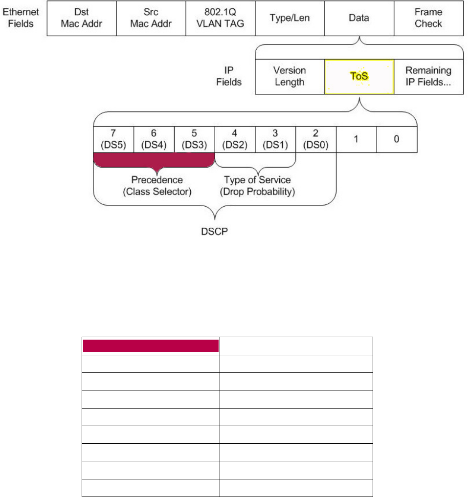
After the VLAN classification, the IP packets are classified according to Precedence bits (3 bits)
of the IP TOS field. These precedence bits map to Diff Serve Code Points (DSCP) bits (DS5-
DS3). Bits 0 and 1 of the TOS field are reserved and are always 0.
Voice Video Normal Background
Precedence
Class of Service
0 Best Effort
1 Background
2 Background
3 Best Effort
4 Video
5 Video
6 Voice
7 Voice

38
If there is no classification, (no VLAN and IP TOS 0) the packet falls under the Best Effort class.
If the packet has both VLAN and IP precedence values, the maximum of the two priorities
(VLAN/IP) is used.
The following table shows the mapping of class of service on various DSCP/TOS values.
Class of Service
IP
Precedence
(3 bits)
DSCP (6 bits)
TOS (8 bits)
Best Effort 0,3 0x0 (0)
0x18 (24)
0x1A (26)
0x1C (28)
0x1E (30)
0x0
0x60
0x68
0x70
0x78
Background 1,2 0x8 (8)
0xA (10)
0xC (12)
0xE (14)
0x10 (16)
0x12 (18)
0x14 (20)
0x16 (22)
0x20
0x28
0x30
0x38
0x40
0x48
0x50
0x58
Video 4,5 0x20 (32)
0x22 (34)
0x24 (36)
0x26 (38)
0x28 (40)
0x2E (46)
0x80
0x88
0x90
0x98
0xA0
0xB8
Voice 6,7 0x30 (48)
0x38 (56)
0xC0
0xE0
Queue mapping
The table below shows the mapping of different types of traffic to hardware queues. The
Hardware MAC consists of 10 Queues starting from 0 to 9. Highest priority Queue is 9 and
typically used for beacons. Next highest priority is 8 and is associated with beacon gated frames.
The remaining 8 queues are used for different types of traffic classes. XL100t only uses queues
0-3 and 9.

39
Queue number
Traffic Type
0 Best Effort
1 Background
2 Video
3 Voice
4 Not used
5 Not used
6 Not used
7 UAPSD - Not used
8 CAB - Not used
9 Beacon
Highest Priority
Lowest Priority
40
14. Advanced Modes
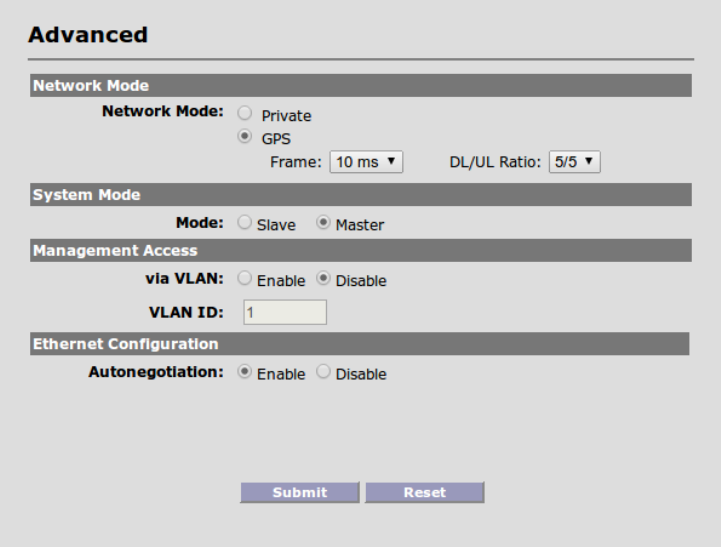
An advanced configuration section is available under Configuration -> Advanced, as shown
below, the top picture is for the base and the bottom picture is for the Slave unit:
Network Mode
The PTP system has two MAC layer operating modes:
Polling MAC: Polling MAC is superior when the application case involves heavy traffic.
Private Network Mode: In certain situations, customers may prefer to use Private network
Mode. For example, performance may be better in a private network where there is a lot of
Slave unit to Slave unit traffic (office branches, server located at a Slave unit building, etc)
41
GPS Mode: This mode should be used when there are co-located Master units at the same time.
In order to use this mode, the Master unit must be a GPS-ready version, e.g. AS5802 instead of
AS5800. The GPS port on the Master unit must be connected to a GPS sync controller.
• Frame – This refers to the time slot (frame) duration that the Master unit allows for each
downlink / uplink cycle. The default value is 10ms. The other choice is 20ms.
• DL/UL Ratio – Each time slot is divided into downlink traffic (DL) and a uplink traffic (UL).
The default is 5:5 (most Enterprise network). Available DL/UL radios are 9:1, 8:2, 7:3,
6:4, 5:5, 4:6, 3:7, 2:8, and 1:9.
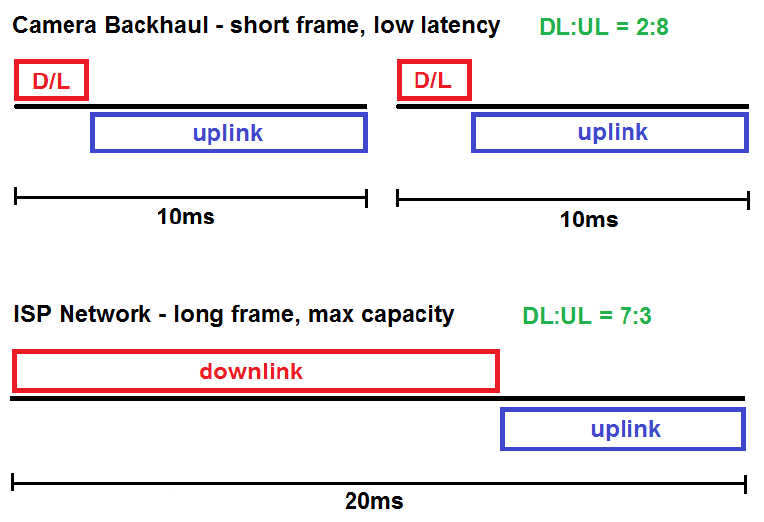
The concepts of frame sizes and DL/UL ratios are explained in the following diagram. The
Master unit operates in a 10ms or 20ms cycle during which downlink and uplink portions are
defined by the DL/UP ratio. During the downlink portion, the Master unit will send data to Slave
units using polling MAC and then the Master unit switches to the uplink portion and Slave units
will send data during that portion of the cycle. This cycle continues during the period defined by
the frame size (10ms or 20ms).
DL/UP ratios should be set in accordance with the application. For example, ISP networks tend
to be downlink heavy with subscriber downloading web contents. In that case, the 7:3 ratio may
be appropriate. For IP camera backhaul, the traffic is dominated by uplink traffic coming from
cameras attached to Slave units. In that case, the 2:8 ratio may be suitable.

42
The longer 20ms frame size reduces the overhead and increase the throughput, but the
drawback is a higher overall latency due to longer cycles. It may not be suitable for latency-
sensitive, real-time applications.
CAUTION – Extreme ratios such as 9:1 and 1:9 should be avoided for most
applications, particularly with the 40MHz channel size operation.
System Mode
A PTP unit can be either a Master unit or Slave unit. One side must be chosen as Master and
the other as Slave. The functions are very similar between the two units, but the Master unit has
a few more control parameters, for which the Slave unit will follow the Base configuration.
Management Access
Via VLAN Enable/Disable. If access to the Web GUI will be from a PC within a VLAN, then
this feature should be Enabled. If access is from a PC outside of a VLAN, then this feature
should be Disabled.
VLAN ID: The ID should be set to match the VLAN ID used on your management PC. This
setting does not affect any other VLANs running on your network or the ability to pass VLAN
traffic.
WARNING - Enabling Management Access via VLAN will lock-out HTTP and
Telnet access if attempting to connect from a PC without the proper VLAN
configuration. Access to units with an unknown VLAN configuration can be
recovered through the use of Solectek’s Recovery utility software on radios running
recent revisions of software. Check with Solectek Support for details.
Ethernet Configuration – This section allows users to configure the Ethernet port manually,
particularly for interfacing with older hardware. Solectek strongly recommends using auto-
negotiation default mode in most cases.
NOTE - Autonegotiation is REQUIRED for 1000BASE-T operation, per the IEEE
802.3-2002 standard: "a) To negotiate that the PHY is capable of supporting
1000BASE-T half duplex or full duplex transmission. b) To determine the
MASTER-SLAVE relationship between the PHYs at each end of the link."
43
15. Telnet
Using the radio’s IP address, the system can be managed using a Telnet connection. The login
and password are the same for a Telnet session as for the HTTP GUI.
Sessions can be initiated from both the Ethernet and RF side of the Network, and multiple
sessions are permitted.
Commonly used commands include:
>status
>get rssi
>get counters
>show log
>uptime
>get <to see read commands>
>set <to see write commands>
>? <to see other commands>
See Appendix B for a complete Telnet command set, syntax and usage.
16. SNMP
The SkyWay management system includes ‘get’ support for SNMP v2c via standard and private
MIB tables. This screen is available at the Master unit only.
Navigate to Management -> SNMP to access the SNMP Configuration screen:
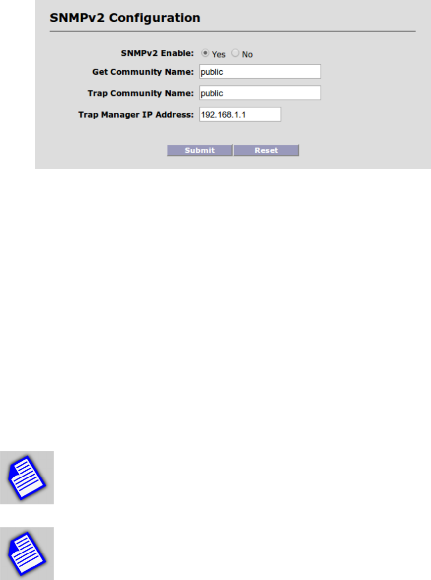
44
SNMP Enable: For security purposes, the SNMP engine can be disabled, if not used.
Community Names and Trap Manager IP Address fields should be entered based on the
configuration of your SNMP Manager software.
The private MIB is available on Solectek’s Support website or from Solectek Technical Support
personnel.
For further information about SNMP management, the following documents available on
Solectek’s Support Website may be helpful:
• SkyWay SNMP Usage Guide
• SNMP Objects for Monitoring SkyWay
NOTE
- SNMP community fields are case sensitive with no spaces allowed.
Fields must be between 1 and 64 characters in length.
NOTE
- Legal characters are: all alphanumerics, plus the following symbols:
@ (at sign) - (dash) . (period) ‘ (tick) _ (underscore)
45
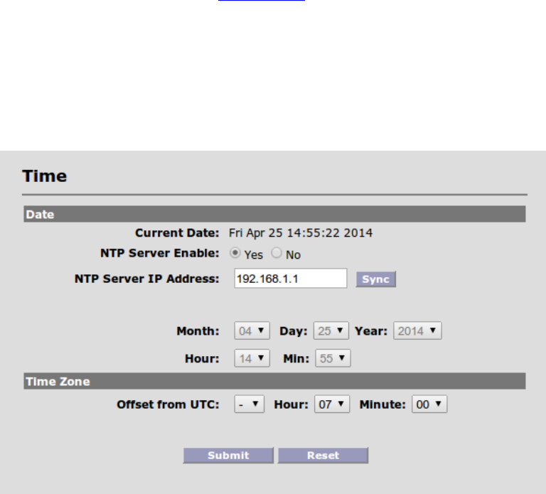
17. Network Time
Using the Network Time Protocol (NTP), the SkyWay XL100t radio can be time synchronized to
an NTP v3/v4 time server as defined by www.ntp.org.
To setup this feature, navigate to Configuration -> Advanced to access the Date and Time
feature configuration:
To time synchronize the radio, the NTP server IP address must be established and the ‘sync’
button pressed. If connection is successful, the local time/date will be updated to match NTP
time.
An NTP resync will occur automatically twice per day.
If the NTP server is off-line, time is still kept locally on the radio. However, a reboot of the unit
will blank the time. A re-connection to the NTP server or manual re-configuration of the time is
required to correct the time/date.
Time zone information must be entered manually as a fixed offset from UTC. Once entered,
this information is stored in non-volatile local memory and does not need to be re-entered.
All changes, except for the NTP Sync function, should be followed by a ‘Submit’ to make active.
46
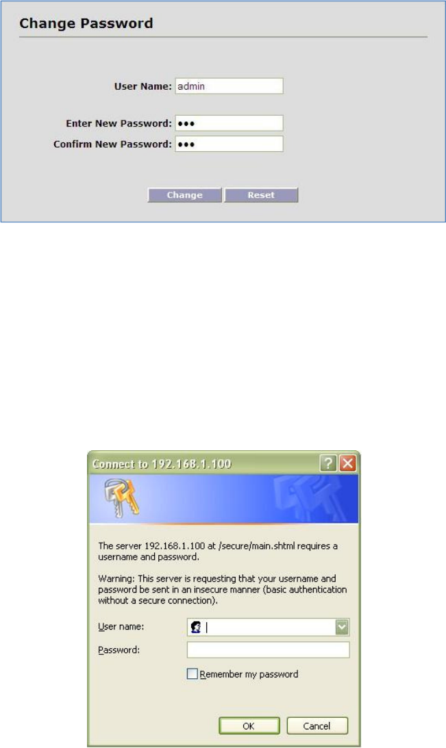
18. Password Management
Navigate to Management -> Password to access the Login configuration screen:
Enter New Password: Enter the new password.
Confirm Password: Re-enter the new password for confirmation.
Select the “Change” button.
The browser will popup a new login window. You must log back in to the system with the new
password.
47
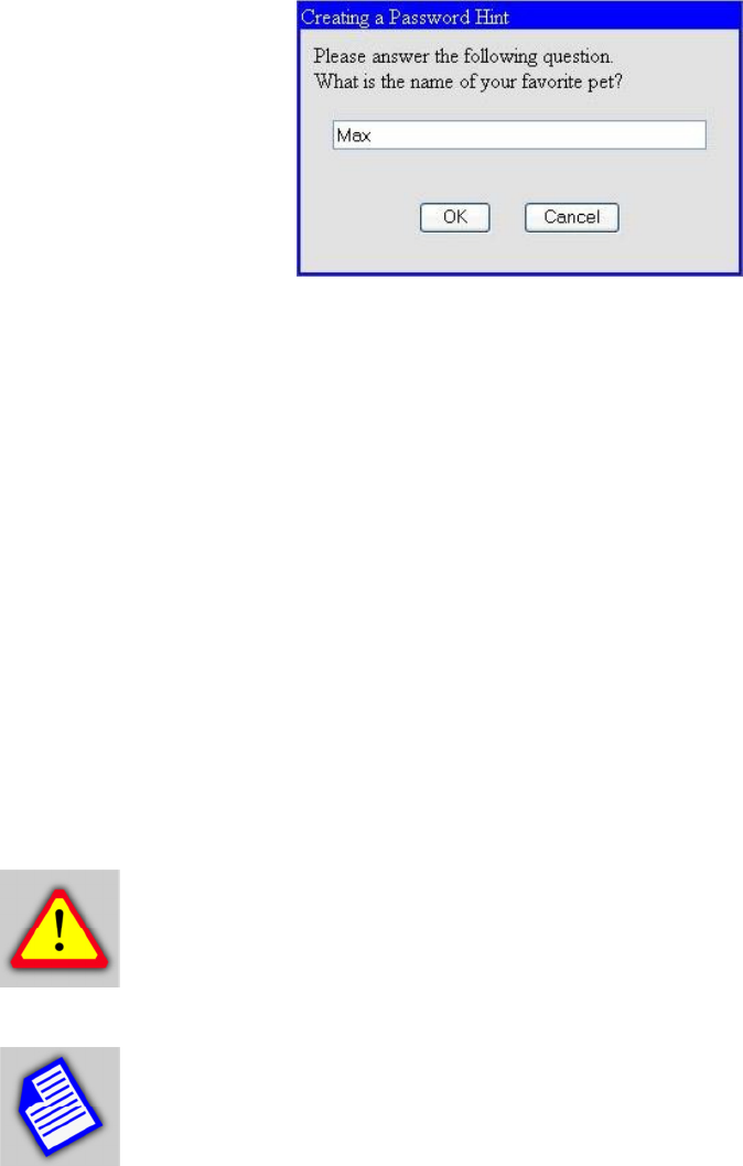
At the time of the first password change, a password ‘hint’ prompt will be displayed.
Once established, this hint answer can be used to reset the admin password, if it has been
forgotten, via the ‘recover’ Telnet login, as follows:
> Login: recover
> Password: (default)
Once logged in as ‘recover’, the hint will be given:
> What is the name of your favorite pet?
Upon successful answer, the admin password can then be changed.
CAUTION - It is strongly advised that the admin password, and hint answer
be recorded and stored in a secure location.
NOTE - Password & hint fields are case sensitive and no spaces are allowed.
Password & hint should be 6-32 characters in length. To avoid a ‘weak password’
warning when changing the password via Telnet, it is required that passwords
contain a mix of uppercase letters, lowercase letters, numbers and symbols.
48
19. Upgrading the Software
There may be new software releases from Solectek periodically posted on Solectek’s support
portal and available from Solectek Technical Support.
The software is comprised of three sections: Firmware, Kernel and Bootloader. However, only
a single upgrade operation is required to bring all three up to the latest revision.
Upgrading the software will not affect the system configuration, but does require a short period
of system downtime to complete the process.
NOTE - A PC based FTP server program running on a locally connected PC
is required to complete the following upgrade procedure. Solectek
recommends FileZilla, a free, open-source FTP server program available via
http://filezilla-project.org/
Once the FTP server is installed, the following procedure should be followed:
1. Copy .zip software release package from Solectek website or Technical Support to FTP
Server desktop.
2. Unzip / extract files to any convenient directory.
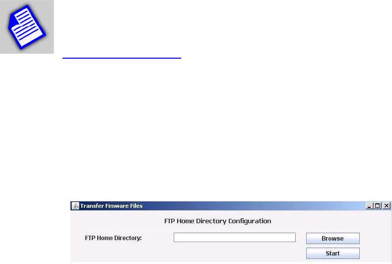
3. Navigate into the extracted fileset to reach the SetupFirmware.exe tool.
4. Launch tool by double-clicking on tool icon; the following screen will be displayed:
5. Press the ‘Browse’ button and select the folder that has been configured as Home
Directory in the FTP server software.
6. Press the ‘Start’ button. This begins a file copy operation and ensures that all upgrade
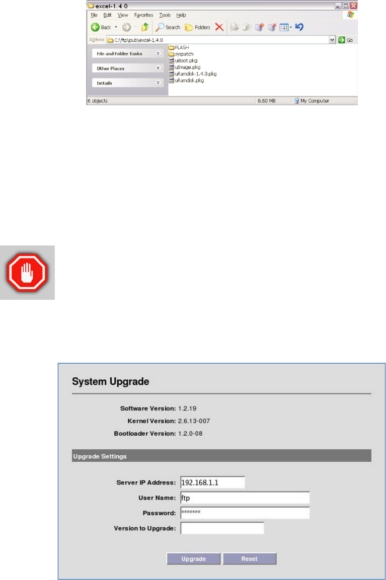
files and folders are properly moved into the FTP directory. Once complete, the resulting
FTP file structure should appear as follows:
49
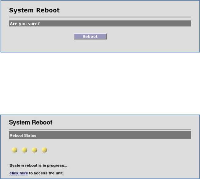
7. On the Radio management GUI, navigate to Management -> Upgrade to access the
Upgrade screen (see sample below).
8. Enter the FTP Server IP Address, Username and Password information as requested.
9. Enter the three digit software version to be loaded onto the Radio. Format will be x.y.0
(e.g. – 1.4.0).
10. Press the ‘Upgrade’ button to begin the file transfer process.
11. Once complete, the unit must be rebooted for the upgrade to take effect.
WARNING - Do not power down or unplug the unit during the upgrade
process. Software image corruption may occur if power is disrupted
during the flash write process.
If the upgrade fails to complete, or times out:
50
- Verify the FTP user account has read permission on the target folder.
- Verify that the FTP server’s software firewall is disabled. For example, Windows XP has an
integrated firewall that can block the upgrade.
- Retry Upgrade procedure.
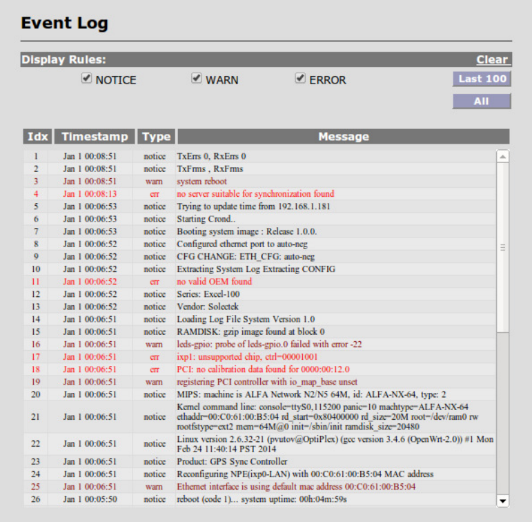
20. System Reboot
Navigate to Reboot to access the System Reboot function:
Click on the Reboot button to reset/reboot. The reboot process will take approximately 60
seconds. Once the rebooting is done, you can use the Click Here button below to access the
user interface again.
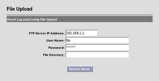
21. Event Log
The Event Log displays all major events that may be noteworthy for the system administrator for
both monitoring and troubleshooting purposes.
51
Navigate to Status -> Event Log to access the Event Log Screen:
There are three categories of events:
Notice: This is informational in monitoring the operation of the unit. A Notice entry is part of the
normal operation.
WARN: This may indicate something wrong with the unit or operation. For example, downing of
the RF port may be due to malfunction or user intervention (power off).
ERROR: This is indicative of unanticipated or erroneous operating conditions.
52
22. Log/Configuration Transfer
For diagnostic purposes, the Event Log and System Configuration database can be transferred
from the Radio to a local PC via FTP. The default names of these files are as follows:
CONFIG_VARS-”system_name”.MMDDYYhhmm
events-”system_name”.MMDDYYhhmm
clients-”system_name”.MMDDYYhhmm
Navigate to Diagnostics -> File Upload to access the following screen:
FTP Server IP Address: Local FTP server address.
User Name: User name used to login to the FTP server.
Password: Password used to login to the FTP server.
File Directory: Location on Local FTP server to save Event and Configuration files. If left
blank, files will be transferred to the FTP server’s home directory.
53
NOTE
- FTP Username and password fields are case sensitive with no spaces
allowed. Fields must be between 1 and 32 characters in length.
NOTE
- Legal characters are: all alphanumerics, plus the following symbols:
@ (at sign) - (dash) . (period) ‘ (tick) _ (underscore)
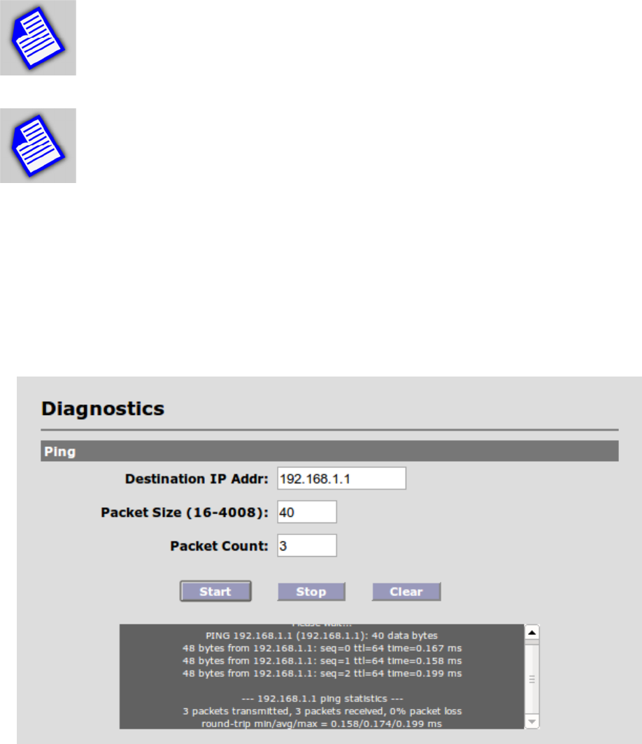
23. Diagnostics
For access to diagnostic tools, navigate to Diagnostics => Time/Ping menu to view the
following:
The ping tool can be used to isolate an issue to the wireless link only, not involving other
network elements such as switches and host computers. You can ping the remote unit from the
unit you are accessing via the user interface.
54
Destination Add: The IP address of the device to be pinged.
Packet Size: The size of the ping packets to be sent (in bytes).
Packet Count: The number of packets to be sent to the destination IP address.
Click on the Start button to initiate the ping session. Click Stop to terminate it.
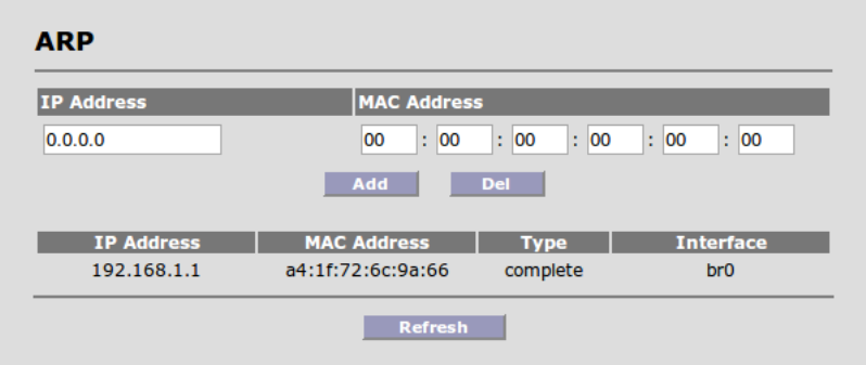
You can also manage and view the status of ARP for both Master unit and Slave unit, as shown
in the screen below:

55
Appendix A: Factory Configuration
WIRELESS
Radio Spectrum bandwidth 20 MHz
Frequency (Master unit-only) Product & Region Specific
RF Power 17 dBm
Modulation QAM16-1/2
Streams 1
Distance 1 miles
RF Network Name Name_1 (Master unit)
Security Open
Access Control List (ACL) Enabled
LAN
IP Address (Slave unit)
IP Address (Master unit)
192.168.1.100
192.168.1.200
IP Mask 255.255.255.0
IP Gateway 192.168.1.1
Login Name / Password admin / admin
Ethernet Port Auto

56
Appendix B: Telnet Commands
Command R/W Default Usage Description
acl RW enabled
acl
add [mac] [client
-
name]
acl del [mac]
acl show
acl [enable | disable]
Master unit only
Add/Delete/Show entries in
the RF access control list.
Enable or Disable acl
function
arp RW arp [OPTION]
Options:
-a Display (all) hosts
-s Set new ARP entry
-d Delete a specified entry
-v Verbose
-n Don't resolve names
-i IF Network interface
-D Read [hwaddr] from
given device
-A, -p AF Protocol family
Manipulate the system ARP
cache
audioalign RW 1800 secs set audioalign [duration_secs]
show audioalign
Set/show Audio Antenna
Alignment duration in
seconds. Duration 0
disables alignment tone.
bridge R
show
bridge
Show Bridge Table
bw RW 20
set
bw
[20 | 40]
show bw
Set RF bandwidth in MHz
chanplan R Varies by Model,
Region
show chanplan Show channel plan.
cfgdiff R cfgdiff [boot] Shows differences between
current configuration and
default
clear W
clear
Clears all Ethernet & RF
Port counters
clearevtlog W
clearevtlog
Clear event log
clientcfg R/W clientcfg <mac> [--name <name>] [--
dlmod <dlmod>] [--dlstr <dlstr>] [--
Show status of and make
changes to configured

57
ulmod <ulmod>
] [
--
ulstr <ulstr>]
clients
clientstat R
client
stat
<mac>
clientstat show - show the status of
all connected clients
Show status of connected
clients
connections R
show connections
Show active connections
counters R
show
counters
Show RF statistics
date RW date [-u]... [MMDDhhmmYYYY
Options:
-u Apply the UTC time zone
offset to the date
Display or set current date
default W
default
Restores system to factory
defaults
distance RW 16 set distance [miles_or_kilometers] -
based on metric setting
show distance
Set distance in miles or
kilometers
encrypt RW open
set
encrypt
[open | AES | radius]
show encrypt
Open: no
authentication/encryption
AES: PSK authentication /
AES encryption
Radius: 802.1x
authentication / AES
encryption
ethcfg RW auto set ethcfg [auto-neg | 10baseT-HD |
10baseT-FD | 100baseTx-HD |
100baseTx-FD]
show ethcfg
Set ethernet speed and
duplex
exit W
Exit
Logout from Telnet session
freq RW Varies by region
set
freq
[frequency]
show freq
Set RF frequency in MHz
ftppass RW p
set
ftppass
[password]
show ftppass
Set remote ftp server
password
ftpuser RW ftp
set
ftpuser
[user]
show ftpuser
Set remote ftp server
username

58
get R
Get
Get commands
gwaddr RW 192.168.1.1
set
gwaddr [a.b.c.d]
show gwaddr
Set default gateway IP
address
help R
help
Show commands
history R
history
Show command history
ipaddr RW 192.168.1.100
Slave unit
192.168.1.200
Master unit
set
ipaddr
[a.b.c.d]
show ipaddr
Set IP address
ipmask RW 255.255.255.0
set
ipmask
[a.b.c.d]
show ipmask
Set IP netmask
log R
show
log
Show Event Log
logout W
logout
Logout from Telnet session
macaddrs R show macaddrs Show Ethernet and RF MAC
addresses
metric W miles set metric [miles | kilometers] Set Distance metric
mod RW QAM16 ½ show mod
set mod [bpsk-1/2 | qpsk-1/2 | qpsk-3/4 |
qam16-1/2 | qam16-3/4 | qam64-2/3 |
qam64-3/4 | AUTO]
Show Current Modulation
name RW (blank)
set
name
[name]
show name
Set system name
ntpaddr RW 192.168.1.1 set ntpadd [a.b.c.d]
show ntpaddr
Set NTP server address
password W Factory default:
admin
Customer
default: retains
password
password
[guest]
Change admin password or
guest password
patchlist R show patchlist Show system patches

59
ping W ping [OPTION]... Host
Options:
-c CNT Send only CNT pings
-s SIZE Send SIZE data bytes
in packets (default=56)
-I iface/IP Use interface or IP
address as source
-q Quiet, only displays
output at start
and when finished
Test network connectivity
power RW 17
set
power
[rfpower]
show power
Set RF Transmit power, in
dBm
product R retains product
show
product
Show product type
psk_phrase RW my-big-secret-
01
set
psk_phrase
[phrase]
show psk_phrase
Set pre-shared key
passphrase
radius_pass RW abcd1234
set
radius_pass
[password]
show radius_pass
Slave unit only
Set Radius user password
radius_secr
et
RW my-big-secret-
01
set
radius_secret
[secret]
show radius_secret
Master unit only
Set Radius secret
radius_serv
er
RW 10.20.20.3 set radius_server [server_ipaddr]
show radius_server
Master unit only. Sets
Radius Server IP address
radius_timer RW 86400
set
radius_timer
[period]
show radius_timer
Master unit only
Set Radius reauthentication
period, in Seconds
radius_user RW wpa1@host.loca
l
set
radius_user
[name]
show radius_user
Slave unit only
Set Radius client user name
reboot W
reboot
Reboot system
rfnetname RW NAME_1
set
rfnetname
[netname]
show rfnetname
Set RF Network Name
rmod RW set rmod [macaddr] [streams] [bpsk-1/2
| qpsk-1/2 | qpsk-3/4 | qam16-1/2 |
qam16-3/4 | qam64-2/3 | qam64-3/4|
AUTO]
Set Remote
Modulation/Streams on

60
route R
show
route
Show IP route table
rssi R
show
rssi
Show Local Recv Signal
Strength
savecfg W
savecfg
Save configuration to
permanent memory
serialnum R
show
serialnum
Show system serial number
set R
set ?
Set ? for commands
show R
show
Show commands
snmp RW
enabled
public – for all
strings
192.168.1.1 for
trap manager
set snmp enable=[yes|no]
set snmp [read-community|rc]=[abcdef]
set snmp [trap-community|tc]=[abcdef]
set snmp [trap-manager|tm]=[a.b.c.d]
show snmp
Set SNMP configuration
parameters
status R
status
Show system status
streams RW 1 show streams
set streams [1 | 2]
Show / Set the number of
MIMO data streams. Limited
to 1 for Access 50.
sysmode RW retains sysmode show sysmode
set sysmode [MULTIPOINT_MASTER |
MULTIPOINT_SLAVE]
Show / Set the MULTIPOINT
operating mode
tz RW “+00:00”
tz
[+hh:mm |
-
hh:mm]
Set/Show time zone
updatesw W updatesw [options] [swver]
Options: -v -verbose output
-b -update uboot
-k -update kernel
-r -update rootfs
-h -use http
-i -ignore existing
configuration
-f -force the update
Download and install new
system software
upload W
upload
config [remotefile]
upload syslog [remotefile]
Upload files to remote server
uptime R
uptime
Display current system
uptime
version R
version
Display current software

61
version
vlan RW disabled
vlan
[enable | disable]
Enable/Disable management
via VLAN
vlanid RW 1
set
vlanid
[vlan id] show vlanid
Set VLAN ID for
management channel
62
Appendix C: Regulatory Information
1. FCC Radio Frequency Interference Statement (5.9 GHz version)
FCC ID: KA359WAN1
This device is certified to comply with Part 15 of Federal Communications Commission (FCC) Rules. Operation is subject to the
following two conditions:
1. It may not cause harmful interference.
2. It must accept any interference that may cause undesired operation.
Changes or modifications not expressly approved by Solectek could void the user’s authority to operate the
equipment.
2. U.S. Government Restricted Rights Legend
The Product is provided with Restricted Rights. Use, duplication, reproduction or disclosure by the Government is
subject to restrictions in subdivision (c)(1)(ii) of the Rights in Technical Data and Computer Product clause at
252.227-7013 and in subparagraphs (a) through (d) of the Commercial Product-Restricted Rights Clause at
52.227-19. Contractor/Manufacturer is Solectek, 8969 Kenamar Dr, Suite 113, San Diego, CA 92121.
3. Radio Transmission Notice
This product is a low power (less than 1 Watt), OFDM radio system pre-set to transmit and receive signals in the
5.850 – 5.925 GHz frequency bands. This product has been certified by the U.S. Federal Communications
Commission for use in the United States of America in that band. Other markings on the unit label shall indicate
regulatory compliance in other international areas.
Any prospective user of this product outside the United States of America should, prior to such use, contact the
government department or other agency responsible for assigning radio frequencies in the country in which use is
proposed to determine whether such department or agency has any objection to operation of the product given
current regulatory label markings on said product, and whether there are any other local devices generating signals
in that band which might be expected to interfere with the operation of this product.
Solectek shall not be responsible for any operation of this product which is in violation of local law, creates
interference harmful to other local devices, or results in a malfunction of this product caused by outside
interference.
This device must be professionally installed and used in strict accordance with the manufacturer's
instructions. The installer shall be responsible for ensuring that the proper antenna is employed so
that the limits in this part are not exceeded, including the requirements of FCC Part 15.203
However, there is no guarantee that interference to radio communications will not occur in a particular commercial
installation. In case the device does cause harmful interference with an authorized radio service, the user/ operator
shall promptly stop operating the device until harmful interference has been limited. Solectek Corporation is not

63
responsible for any radio or television interference caused by unauthorized modification of this device or the
substitution or attachment of connecting cables and equipment other than specified by Solectek Corporation. The
correction of interference caused by such unauthorized modification, substitution, or attachment will be the
responsibility of the user.
4. Warning
The antennas used for this transmitter must be installed to provide a separation distance of at least 100 cm from all
persons and must not be co-located or operating in conjunction with any other antenna or transmitter
This device has been designed to operate with the antennas listed below, and having a maximum gain
of 23 dBi. Antennas not included in this list or having a gain greater than 23 dBi are strictly prohibited
for use with this device. The required antenna impedance is 50 ohms.
• MTI Wireless 5.9 GHz 60, 90, and 120 deg Sector antenna
• ARC Wireless Solutions 5.9 GHz 23dBi/20dBi Dual Polarization Panel Antenna
The use of the last two Antennas above shall be restricted to Point-to-Point use only.
This equipment has been tested and found to comply with the limits for a Class A digital device, pursuant to part
15 of the FCC Rules. These limits are designed to provide reasonable protection against harmful interference when
the equipment is operated in a commercial environment. This equipment generates, uses and can radiate radio
frequency energy and, if not installed and used in accordance with the instruction manual, may cause harmful
interference to radio communications. Operation of this equipment in a residential area is likely to cause harmful
interference in which case the user will be required to correct the interference at his own expense.
Information contained in this document is subject to change without notice.
Solectek Corporation shall not be liable for errors contained herein or for
incidental or consequential damage in connection with the furnishing,
performance, or use of this material. Reproduction, adaptation, or translation
without prior written permission is prohibited, except as allowed under the
copyright laws.
Solectek Corporation makes no warranty of any kind with regard to this material,
including, but not limited to, the implied warranties or merchantability and fitness
for a particular purpose.
NOTE: Changes or modifications not expressly approved by Solectek could void the user’s authority to
operate the equipment.
SkyWay and Solectek are registered trademarks of Solectek Corporation. Windows is the
trademark of Microsoft Corp. Google is a trademark of Google, Inc.
Copyright 2014, Solectek Corp. All rights reserved.