Solectek 70MOB1 Broadband Wireless Base Station User Manual KA370MOB1
Solectek Corporation Broadband Wireless Base Station KA370MOB1
UserManual.wiki
>
Solectek
>
70MOB1 User Manual
Users Manual
Navigation menu
Upload a User Manual
Namespaces
Wiki Guide
HTML
PDF
Info
Views
User Manual
Discussion / Help
Navigation
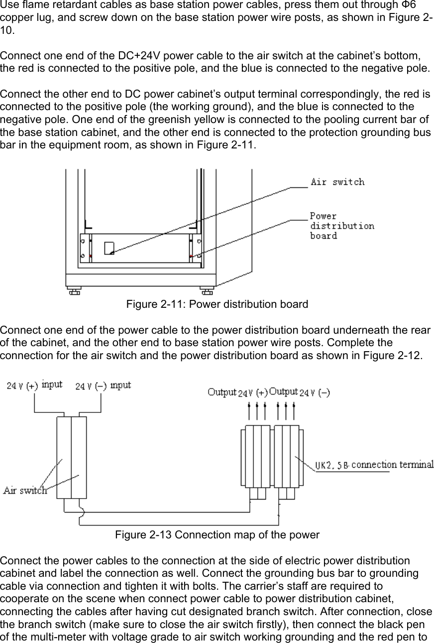
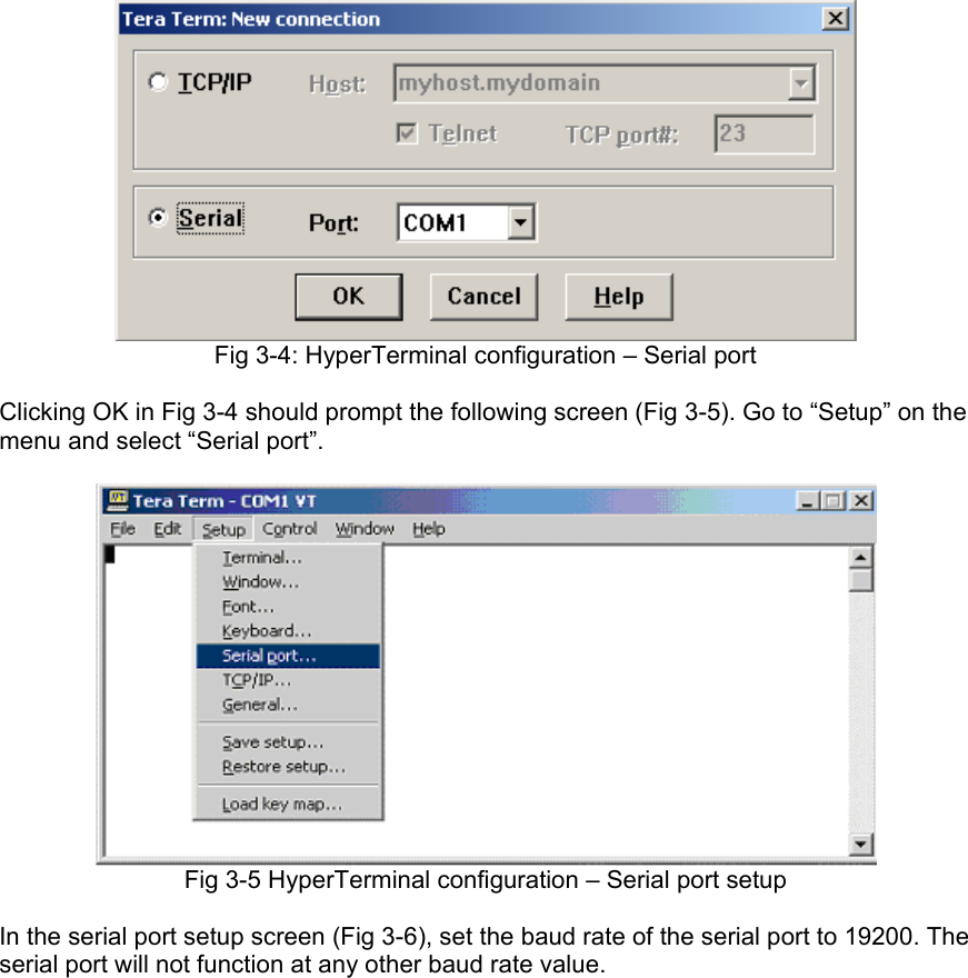
![Fig 3-2: Window to specify the server path 3.2.3 HyperTerminal configuration Make sure that the computer is furnished with HyperTerminal software. Tera Term Pro software is strongly recommended and it can be downloaded from a shareware website. Click desktop shortcut to run HyperTerminal software. The following screen will show upon startup: Fig 3-3 HyperTerminal configuration Select “serial”, “COM1” port and click [OK] button (Fig 3-4)](https://usermanual.wiki/Solectek/70MOB1/User-Guide-1170071-Page-14.png)
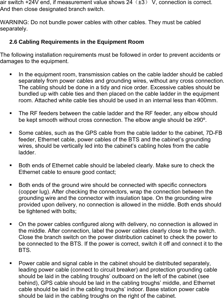
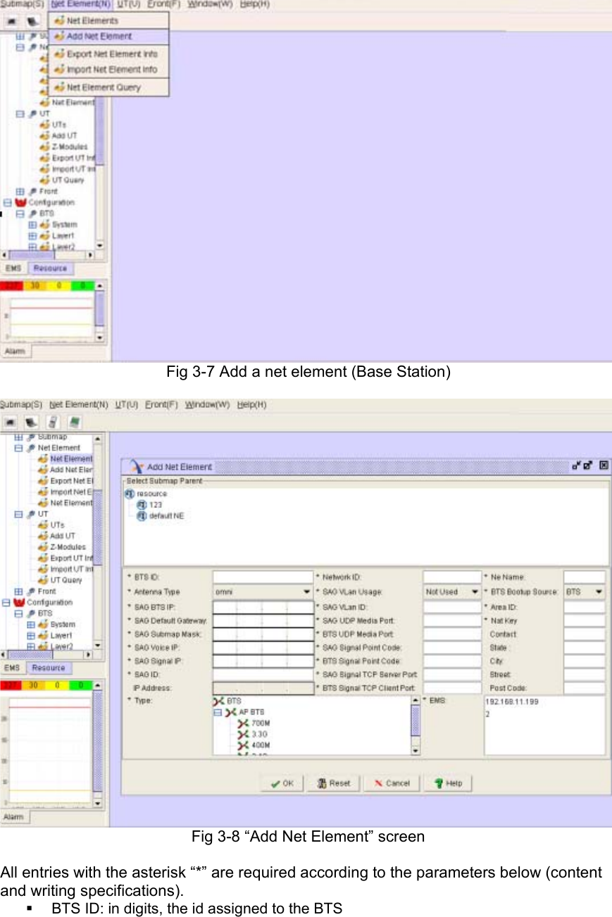
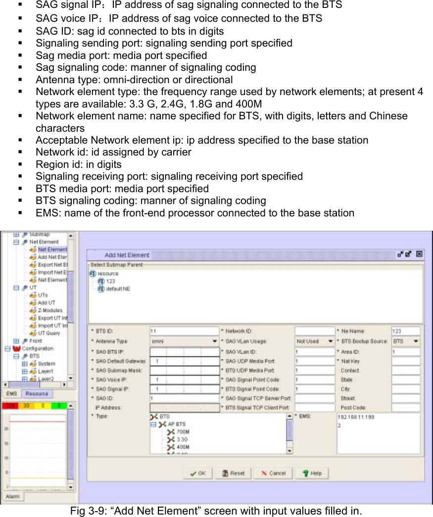
![Fig 3-6 HyperTerminal configuration (4) The serial port is now successfully configured and can be used for configuring information (such as IP address) for connected base station so that the base station is linked to the EMS server. 3.3 Add a BTS in EMS Server If the client program is running in EMS Server computer, click [Resource Management] to add new base station. Here only some necessary configurations are required, such as base station name, ID, IP address, subnet mask and network gateway, etc, which should be filled in according to your system network plan design. Go to “Net Element” and select “Add Net Element” (Fig 3-7) and the “Add Net Element” screen will be shown (Fig 3-8).](https://usermanual.wiki/Solectek/70MOB1/User-Guide-1170071-Page-16.png)
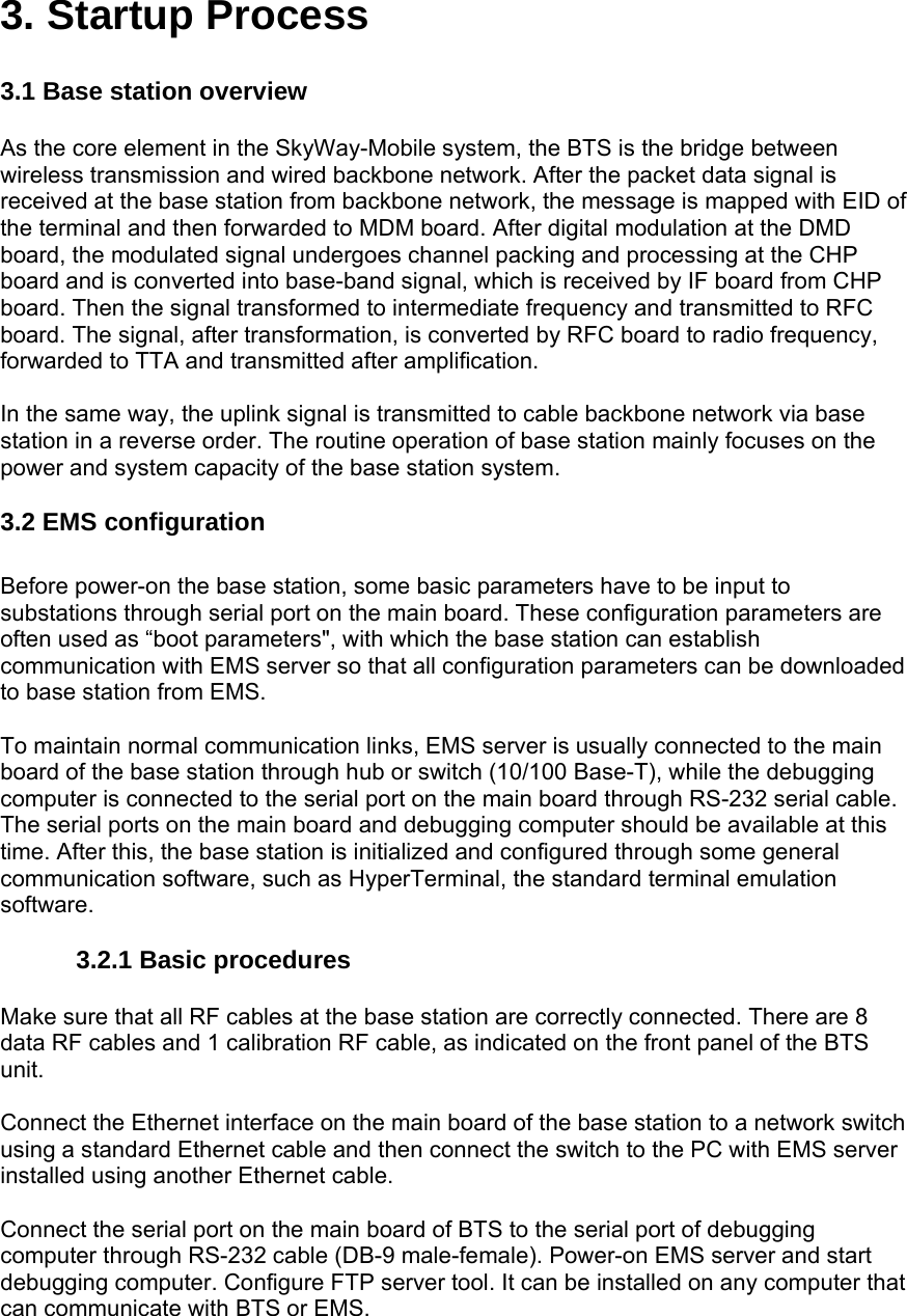
![Press any key on the keyboard to stop automatic startup and input configuration information to configure base station: Now there will be a boot message in HyperTerminal screen: [VxWorks Boot]: This message provides some operations of simple commands. Input “?” or “h” and press [Enter] to display a set of commands (and examples). To use any command, just input character command with optional parameters and press [Enter]. Boot Commands [VxWorks Boot]: ? ? - print this list @ - boot (load and go) p - print L3 boot params P - print L2 boot params c - change L3 boot params C - change L2 boot params l - load boot file g adrs - go to adrs d adrs[,n] - display memory m adrs - modify memory f adrs, nbytes, value - fill memory t adrs, adrs, nbytes - copy memory e - print fatal exception v - print boot logo with version n netif - print network interface device address $dev(0,procnum)host:/file h=# e=# b=# g=# u=usr [pw=passwd] f=# tn=targetname s=script o=other boot device: ata=ctrl,drive file name: /ata0/vxWorks Boot flags: 0x02 - load local system symbols 0x04 - don't autoboot 0x08 - quick autoboot (no countdown) 0x20 - disable login security 0x40 - use bootp to get boot parameters 0x80 - use tftp to get boot image 0x100 - use proxy arp available boot devices:Enhanced Network Devices mv0 ata Explanations of all commands: @ -Used when all parameters are set as required. This command will continue to execute previously cancelled boot initialization process. p - This command will display a brief description of L3 parameters in current boot configuration. P - This command will display a brief description of L2 parameters in current boot configuration. c - This command can be used to change current L3 boot parameters. Once this command is selected, a detailed option list will be displayed. Modify and overwrite it. When all options are modified, the system will return to [VxWorks Boot]: message. During these processes, press [Enter] to accept current parameters value or input new parameters value and press [Enter] to confirm. Besides, input “.” and press [Enter] to clear current value of this entry and restore it to default. If any error occurs, process “-(hyphen)” and [Enter] to return to previous option. Or you can continue this erroneous entry and modify it when returning to [VxWorks Boot]: command line.](https://usermanual.wiki/Solectek/70MOB1/User-Guide-1170071-Page-20.png)
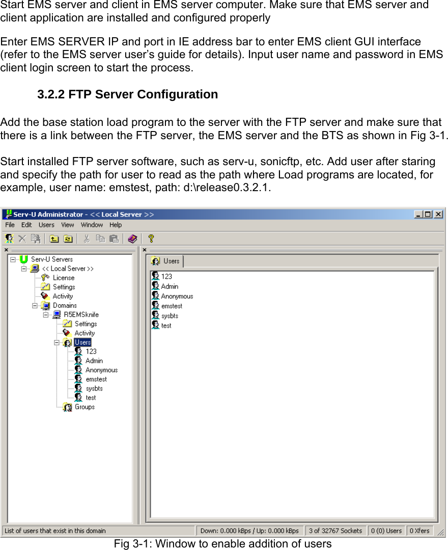
![ C - This command can be used to change current L2 boot parameters. Once this command is selected, a detailed option list will be displayed. Modify and overwrite it. When all options are modified, the system will return to [VxWorks Boot]: message. During these processes, press [Enter] to accept current parameters value or input new parameters value and press [Enter] to confirm. Besides, input “.” and press [Enter] to clear current value of this entry and restore it to default. If any error occurs, process “-(hyphen)” and [Enter] to return to previous option. Or you can continue this erroneous entry and modify it when returning to [VxWorks Boot]: command line. d - display memory usage; the user-defined base station memory to be displayed can be viewed here. This operation can only be conducted by Solectek certified technical support engineer. m - modify memory. This option allows the user to change allocation of base station memory as per the user’s requests. This operation can only be conducted by Solectek certified technical support engineer. f - fill memory. This option allows changing BTS memory with a set mode. This operation can only be conducted by Solectek certified technical support engineer. t - fill memory. This option allows changing BTS memory with a set mode from other memory area. This operation can only be conducted by Solectek certified technical support engineer. Input “c” to configure L3. [VxWorks Boot]: c '.' = clear field; '-' = go to previous field; ^D = quit boot device : mv0 :Boot BTS from ftp server processor number : 0 host name : hy :host username file name : l3_image :filename of L3 startup inet on ethernet (e) : 192.168.17.160:ffffff00 :IP and subnet mask of L3 inet on backplane (b): 10.0.0.1 :IP of L3’s BP host inet (h) : 192.168.11.199 :IP of ftp server gateway inet (g) : 192.168.17.1 :IP of L3’s gateway user (u) : emstest :username of ftp server ftp password (pw) (blank = use rsh): emstest :FTP password flags (f) : 0x0 target name (tn) : startup script (s) : other (o) : [VxWorks Boot]: Input “C” to configure L2. [VxWorks Boot]: C '.' = clear field; '-' = go to previous field; ^D = quit boot device : mv0 :Boot BTS from ftp server processor number : 0 host name : hy :host username file name : l2_image.bin :filename of L2 startup inet on ethernet (e) : 192.168.17.161:ffffff00 :IP and subnet mask of L2 inet on backplane (b): 10.0.0.2 :IP of L2’s BP host inet (h) : 192.168.11.199 :IP of ftp server](https://usermanual.wiki/Solectek/70MOB1/User-Guide-1170071-Page-21.png)
![gateway inet (g) : 192.168.17.1 :IP of L3’s gateway user (u) : emstest :username of ftp server ftp password (pw) (blank = use rsh): emstest :FTP password flags (f) : 0x0 target name (tn) : startup script (s) : other (o) : 0.250.0.37 [VxWorks Boot]: Input “p” to view L3 configuration. [VxWorks Boot]: p boot device : mv unit number : 0 processor number : 0 host name : hy file name : l3_image inet on ethernet (e) : 192.168.17.160:ffffff00 inet on backplane (b): 10.0.0.1 host inet (h) : 192.168.11.199 gateway inet (g) : 192.168.17.1 user (u) : emstest ftp password (pw) : emstest flags (f) : 0x0 Input “P” to view L2 configuration. [VxWorks Boot]: P boot device : mv unit number : 0 processor number : 0 host name : hy file name : l2_image.bin inet on ethernet (e) : 192.168.17.161:ffffff00 inet on backplane (b): 10.0.0.2 host inet (h) : 192.168.11.199 gateway inet (g) : 192.168.17.1 user (u) : emstest ftp password (pw) : emstest flags (f) : 0x0 other (o) : 0.250.0.37 Boot process [VxWorks Boot]: @ boot device : mv unit number : 0 processor number : 0 host name : hy file name : l3_image inet on ethernet (e) : 192.168.17.160:ffffff00 inet on backplane (b): 10.0.0.1 host inet (h) : 192.168.11.199 gateway inet (g) : 192.168.17.1 user (u) : emstest ftp password (pw) : emstest flags (f) : 0x0 Attached TCP/IP interface to mv0.](https://usermanual.wiki/Solectek/70MOB1/User-Guide-1170071-Page-22.png)
![Attaching network interface lo0... done. Loading... 4365424 Starting at 0x10000... ataDrv returned ERROR from usrRoot. ataDrv returned ERROR from usrRoot. Error during ataDevCreate: d0003 Attached TCP/IP interface to mv unit 0 Attaching interface lo0...done Adding 8580 symbols for standalone. ]]]]]]]]]]]]]]]]]]]]]]]]]]]]]]]]]]]]]]]] ]]]]]]]]]]]]]]]]]]]]]]]]]]]]]]]]]]]]]]] ]]]]]]]]]]]]]]]]]]]]]]]]]]]]]]]]]]]]]] ]]]]]]]]]]] ]]]] ]]]]]]]]]] ]] ]]]] (R) ] ]]]]]]]]] ]]]]]] ]]]]]]]] ]] ]]]] ]] ]]]]]]] ]]]]]]]] ]]]]]] ] ]] ]]]] ]]] ]]]]] ] ]]] ] ]]]] ]]] ]]]]]]]]] ]]]] ]] ]]]] ]] ]]]]] ]]]] ]]] ]] ] ]]] ]] ]]]]] ]]]]]] ]] ]]]]]]] ]]]] ]] ]]]] ]]]]] ] ]]]] ]]]]] ]]]]]]]] ]]]] ]] ]]]] ]]]]]]] ]]]] ]]]]]] ]]]]] ]]]]]] ] ]]]]] ]]]] ]] ]]]] ]]]]]]]] ]]]] ]]]]]]] ]]]]] ] ]]]]]] ] ]]] ]]]] ]] ]]]] ]]]] ]]]] ]]]] ]]]]]]]] ]]]]] ]]] ]]]]]]] ] ]]]]]]] ]]]] ]]]] ]]]] ]]]]] ]]]]]]]]]]]]]]]]]]]]]]]]]]]]]] ]]]]]]]]]]]]]]]]]]]]]]]]]]]]] Development System ]]]]]]]]]]]]]]]]]]]]]]]]]]]] ]]]]]]]]]]]]]]]]]]]]]]]]]]] VxWorks version 5.5.1 ]]]]]]]]]]]]]]]]]]]]]]]]]] KERNEL: WIND version 2.6 ]]]]]]]]]]]]]]]]]]]]]]]]] Copyright Wind River Systems, Inc., 1984-2003 CPU: 7447A Power PC. Processor #0. Memory Size: 0xe000000. BSP version 1.0/ 0. WDB Comm Type: WDB_COMM_END WDB: Ready. Note that there are only 3 seconds to modify configuration: if the first letter is not “m”, the system will automatically start up, causing configuration failure. L3 booting c -config, p - display, b -boot parameter, h/? - help, @ boot [BOOT]: c '.' = clear field; '-' = go to previous field; ^D = quit btsId : 160 :Configure base station ID specified in EMS vlanId (0~4095) : 0 :Configure vlan port dataSource(0-bts/1ems): 0 :Configure base station startup source ems IP : 192.168.17.125 192.168.11.199 :Configure EMS server IP emsRcvPort(D=3999) : 3999 :EMS port number, usually d efault btsRcvPort(D=8002) : 8002 :bts port number, usually d efault](https://usermanual.wiki/Solectek/70MOB1/User-Guide-1170071-Page-23.png)
![rtc year : 2006 :Configure year rtc month : : 11 :Configure month rtc day : 8 :Configure date rtc hour : 11 :Configure hour rtc minute : : 11 : Configure minute rtc second : : 2 :Configure second [BOOT]:BS booting [BOOT]: @ L3 Application booting.............................. Done Now bts is successfully started. bts(160) L3->3b55bae0 tCleanUp:0000 L3DataEB.cpp( 840) : CleanUp sta rt monitoring. SatellitesVisible = 0 StatellitesTrack = 0 BootSrc = 0 RfMask = 0X00FF SyncCardTemperature = 0 DigitalBoardTemperature = 0 TimePassedSinceBtsBoot = 0 seconds [2006/11/08 11:11:0] [tSys] BTS software version: 0.3.2.1 :Display BTS software version [2006/11/08 11:11:0] [tSys] BTS boot normal! [2006/11/08 11:11:0] tSys create ok! [2006/11/08 11:11:0] tEmsRx create ok! [2006/11/08 11:11:0] tEmsTx create ok! [2006/11/08 11:11:0] [tDiagL2L3EMS] create m_sfdl2l3[15] ok! [2006/11/08 11:11:0] [tDiagL2L3EMS] create m_sfdl3ems[16] ok! [2006/11/08 11:11:0] tDiagL2L3Ems create ok! [2006/11/08 11:11:0] [tDiagEMSL3L2] create m_sfdemsl3[17] ok! [2006/11/08 11:11:0] [tDiagEMSL3L2] create m_sfdl3l2[18] ok! [2006/11/08 11:11:0] tDiagEmsL3L2 create ok!. [2006/11/08 11:11:0] tAlarm create ok! [2006/11/08 11:11:0] tCfg create ok! [2006/11/08 11:11:0] mode = tFileM create ok! 0 [2006/11/08 11:11:0] tFtpC create ok! [2006/11/08 11:11:0] tCpeM create ok!. mode 0: no hold; 1: enable position hold; 2:enable altitude hold; 3: autosite survey [2006/11/08 11:11:0] tGps create ok! [2006/11/08 11:11:0] tPM create ok! [2006/11/08 11:11:0] [tSys] All OAM tasks create ok! :system se lf-test over [2006/11/08 11:11:0] [tSys] Send Register Notify to EMS[192.168.11. 199] @state[0] bts send register message to ems server [2006/11/08 11:11:0] [BTS boot] ==> BTS booting from FTP server [2006/11/08 11:11:0] [tSys] BTS send to EMS register response, stat e[0] [2006/11/08 11:11:0] [tSys] BTS register SUCCEED. Bts register succeed [2006/11/08 11:11:0] [BTS boot] ==> Download file :l2_image.bin fin ished [2006/11/08 11:11:0] [BTS boot] ==> Download file :app_mcp.out fini shed [2006/11/08 11:11:0] [BTS boot] ==> Download file :app_aux.out fini shed [2006/11/08 11:11:0] [BTS boot] ==> Download file :app_fep.out fini shed](https://usermanual.wiki/Solectek/70MOB1/User-Guide-1170071-Page-24.png)
![[2006/11/08 11:11:0] [BTS boot] ==> Download file :fpga_L2.out fini shed [2006/11/08 11:11:0] [BTS boot] ==> Download file :fpga_L1.out fini shed [2006/11/08 11:11:0] [BTS boot] ==> Download file :fpga_FEP0.out fi nished [2006/11/08 11:11:0] [BTS boot] ==> Download file :fpga_FEP1.out fi nished Download booting file is now completed. [2006/11/08 11:11:0] [BTS boot] ==> FPGA download started [2006/11/08 11:11:0] [BTS boot] ==> FPGA download succeed [2006/11/08 11:11:0] [BTS boot] ==> Reset FPGA Start the FPGA circuit module. [2006/11/08 11:11:0] [BTS boot] ==> Reset AUX :Start AUX cir cuit module. [2006/11/08 11:11:0] [BTS boot] ==> Reset L2 PowerPC system [2006/11/08 11:11:0] [BTS boot] ==> L2 PreLoader is ready to accept L2 Image [2006/11/08 11:11:0] [BTS boot] ==> L2 PPC image download finished [2006/11/08 11:11:0] L2 PCI interface is ready for message exchange [2006/11/08 11:11:0] [tSys] BTS L2 boot up SUCCESS BTS L2 boot is now completed [2006/11/08 11:11:0] [BTS boot] ==> MCP 0 reset, start code download [2006/11/08 11:11:0] [BTS boot] ==> MCP 1 reset, start code download [2006/11/08 11:11:0] [BTS boot] ==> MCP 2 reset, start code download [2006/11/08 11:11:0] [BTS boot] ==> MCP 3 reset, start code download [2006/11/08 11:11:0] [BTS boot] ==> MCP 4 reset, start code download [2006/11/08 11:11:0] [BTS boot] ==> MCP 5 reset, start code download [2006/11/08 11:11:0] [BTS boot] ==> MCP 6 reset, start code download [2006/11/08 11:11:0] [BTS boot] ==> MCP 7 reset, start code download [2006/11/08 11:11:0] [BTS boot] ==> AUX Reset, start AUX code download [2006/11/08 11:11:0] [tSys] BTS MCP[0] boot up SUCCESS [2006/11/08 11:11:0] [tSys] BTS MCP[1] boot up SUCCESS [2006/11/08 11:11:0] [tSys] BTS MCP[2] boot up SUCCESS [2006/11/08 11:11:0] [tCpeM] receive msg[0x3706] from task[57] [2006/11/08 11:11:0] [tSys] BTS MCP[3] boot up SUCCESS [2006/11/08 11:11:0] [tSys] BTS MCP[4] boot up SUCCESS [2006/11/08 11:11:0] [tSys] BTS MCP[5] boot up SUCCESS [2006/11/08 11:11:0] [tSys] BTS MCP[6] boot up SUCCESS [2006/11/08 11:11:0] [tSys] BTS MCP[7] boot up SUCCESS MSP circuit module boot is now completed [2006/11/08 11:11:0] [tSys] BTS AUX boot up SUCCESS [2006/11/08 11:11:0] [BTS boot] ==> Reset FEP 0 [2006/11/08 11:11:0] [BTS boot] ==> Reset FEP 1 [2006/11/08 11:11:0] [BTS boot] ==> FEP 0 reset, start code download [2006/11/08 11:11:0] [BTS boot] ==> FEP 1 reset, start code download [2006/11/08 11:11:0] [tSys] BTS FEP[0] boot up SUCCESS [2006/11/08 11:11:0] [tSys] BTS FEP[1] boot up SUCCESS](https://usermanual.wiki/Solectek/70MOB1/User-Guide-1170071-Page-25.png)
![FEP circuit module boot is now completed [2006/11/08 11:11:0] [BTS boot] ==> Whole BTS boot finished [2006/11/08 11:11:0] [tSys] BTS standby version: 0 [2006/11/08 11:11:0] [tSys] Send BTS Reset Notify to EMS. [2006/11/08 11:11:0] [tSys] BTS boot from NvRam. L2 AIR LINK DATA:#################################### btsid = 000000A0 networkid = 00000001 reset cnt = 0017 seqid = 00 subcgmask = 1F timeslotn = 08 dltsnum = 04 BCHSCG = 02 FF FF FF FF FF FF FF FF FF BCHTS = 01 FF FF FF FF FF FF FF FF FF RRCHSCG = 02 FF FF FF FF FF FF FF FF FF RRCHTS = 03 FF FF FF FF FF FF FF FF FF RACHSCG = 02 FF FF FF FF FF FF FF FF FF FF FF FF FF FF FF FF FF FF F F RACHTS = 02 FF FF FF FF FF FF FF FF FF FF FF FF FF FF FF FF FF FF F F maxscale = 2000 premscale = E4F BCHSCALE = 0EAE 0C8E 0EAE[2006/11/08 11:11:0] [tSys] BTS boot up SU CCESS. 0EAE 0000 0000 0000 0000 TCHSCALE = 03D7 03D7 03D7 03D7 0000 0000 0000 0000 W0I = 1DB1 D8B5 E4BD 2CAB 2CAB E4BD D8B5 1DB1 W0Q = DF1B EBE8 2312 0000 0000 2312 EB65 0000 [2006/11/08 11:11: 0] [tCfg] receive msg = 0x2012 [2006/11/08 11:11:0] [tCfg]Boot from NvRam! please wait... [2006/11/08 11:11:0] [tCfg] receive msg = 0x2028 [2006/11/08 11:11:0] [tCfg] receive msg = 0x2025 [2006/11/08 11:11:0] [tCfg] receive msg = 0x2022 [2006/11/08 11:11:0] [tCfg] receive msg = 0x202b [2006/11/08 11:11:0] [tCfg] receive msg = 0x0011 [2006/11/08 11:11:0] [tCfg] receive msg = 0x0029 [2006/11/08 11:11:0] [tCfg] receive msg = 0x0015 [2006/11/08 11:11:0] [tCfg] receive msg = 0x3038 [2006/11/08 11:11:0] [tCfg] receive msg = 0x3002 [2006/11/08 11:11:0] [tCfg] receive msg = 0x3005 [2006/11/08 11:11:0] [tCfg] receive msg = 0x3008 [2006/11/08 11:11:0] [tCfg] receive msg = 0x300b [2006/11/08 11:11:0] [tCfg] receive msg = 0x3015 [2006/11/08 11:11:0] [tCfg] receive msg = 0x3018 [2006/11/08 11:11:0] [tCfg] receive msg = 0x301b [2006/11/08 11:11:0] [tCfg] receive msg = 0x301b [2006/11/08 11:11:0] [tCfg] receive msg = 0x301b [2006/11/08 11:11:0] [tCfg] receive msg = 0x301b [2006/11/08 11:11:0] [tCfg] receive msg = 0x301b [2006/11/08 11:11:0] [tCfg] receive msg = 0x301b [2006/11/08 11:11:0] [tCfg] receive msg = 0x301b [2006/11/08 11:11:0] [tCfg] receive msg = 0x301b [2006/11/08 11:11:0] [tCfg] receive msg = 0x301b [2006/11/08 11:11:0] [tCfg] receive msg = 0x301b [2006/11/08 11:11:0] [tCfg] receive msg = 0x301b [2006/11/08 11:11:0] [tCfg] receive msg = 0x301b [2006/11/08 11:11:0] [tCfg] receive msg = 0x301b [2006/11/08 11:11:0] [tCfg] receive msg = 0x301b](https://usermanual.wiki/Solectek/70MOB1/User-Guide-1170071-Page-26.png)
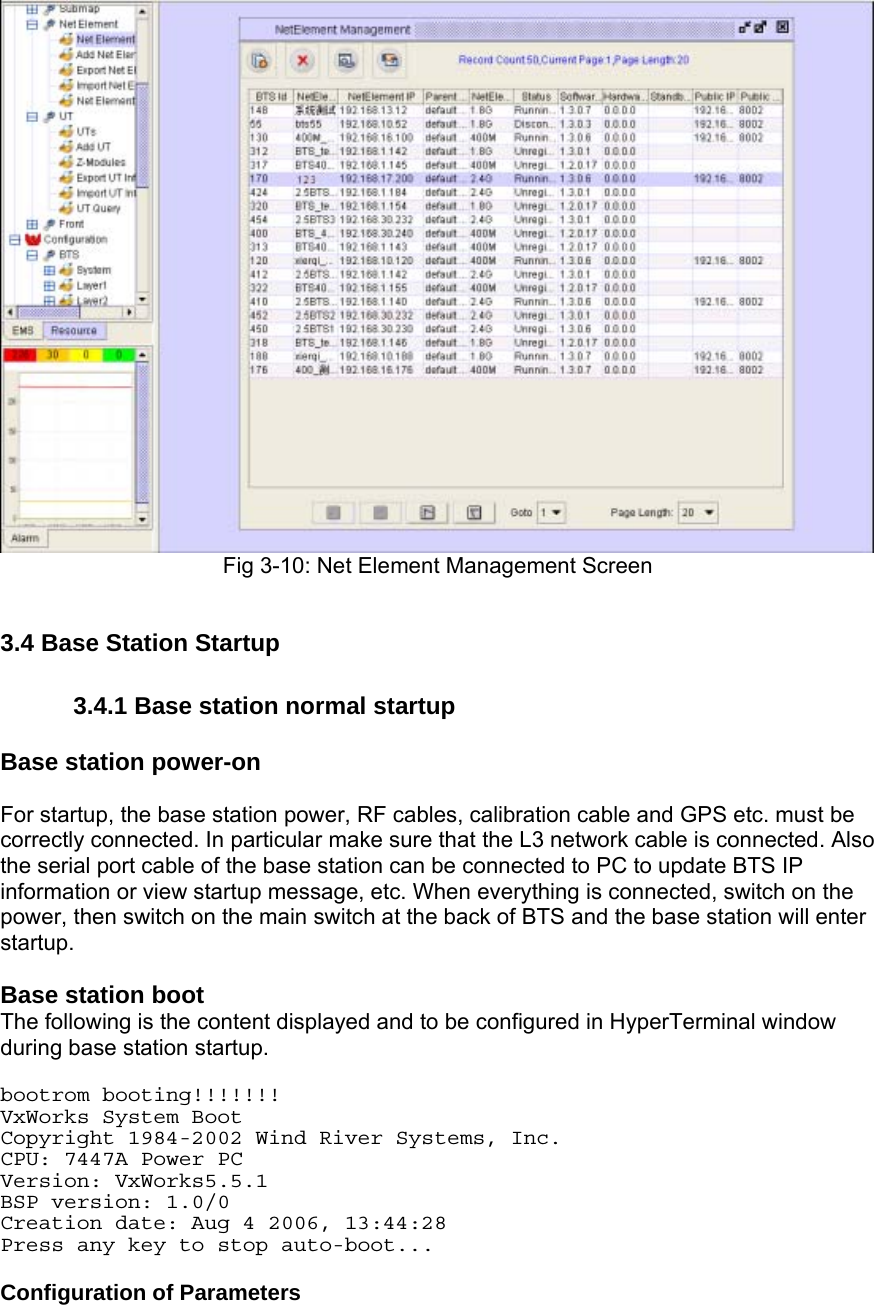
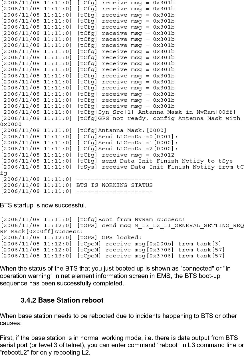
![[2006/11/08 11:11:0] [tCfg] receive msg = 0x301b [2006/11/08 11:11:0] [tCfg] receive msg = 0x301b [2006/11/08 11:11:0] [tCfg] receive msg = 0x301b [2006/11/08 11:11:0] [tCfg] receive msg = 0x301b [2006/11/08 11:11:0] [tCfg] receive msg = 0x301b [2006/11/08 11:11:0] [tCfg] receive msg = 0x301b [2006/11/08 11:11:0] [tCfg] receive msg = 0x301b [2006/11/08 11:11:0] [tCfg] receive msg = 0x301b [2006/11/08 11:11:0] [tCfg] receive msg = 0x301b [2006/11/08 11:11:0] [tCfg] receive msg = 0x301b [2006/11/08 11:11:0] [tCfg] receive msg = 0x301b [2006/11/08 11:11:0] [tCfg] receive msg = 0x301b [2006/11/08 11:11:0] [tCfg] receive msg = 0x301b [2006/11/08 11:11:0] [tCfg] receive msg = 0x301b [2006/11/08 11:11:0] [tCfg] receive msg = 0x301b [2006/11/08 11:11:0] [tCfg] receive msg = 0x301b [2006/11/08 11:11:0] [tCfg] receive msg = 0x301b [2006/11/08 11:11:0] [tCfg] receive msg = 0x301b [2006/11/08 11:11:0] [tCfg]Syn_Src[1] Antanna Mask in NvRam[00ff] [2006/11/08 11:11:0] [tCfg]GPS not ready, config Antenna Mask with 0x0000 [2006/11/08 11:11:0] [tCfg]Antanna Mask:[0000] [2006/11/08 11:11:0] [tCfg]Send L1GenData0[0001]: [2006/11/08 11:11:0] [tCfg]Send L1GenData1[0000]: [2006/11/08 11:11:0] [tCfg]Send L1GenData2[0000]: [2006/11/08 11:11:0] [tCfg] receive msg = 0x3012 [2006/11/08 11:11:0] [tCfg] send Data Init Finish Notify to tSys [2006/11/08 11:11:0] [tSys] receive Data Init Finish Notify from tC fg [2006/11/08 11:11:0] ===================== [2006/11/08 11:11:0] BTS IS WORKING STATUS [2006/11/08 11:11:0] ===================== BTS startup is now successful. [2006/11/08 11:11:0] [tCfg]Boot from NvRam success! [2006/11/08 11:12:0] [tGPS] send msg M_L3_L2_L1_GENERAL_SETTING_REQ RF Mask[0x00ff]success! [2006/11/08 11:12:0] [tGPS] GPS locked! [2006/11/08 11:12:0] [tCpeM] receive msg[0x200b] from task[3] [2006/11/08 11:12:0] [tCpeM] receive msg[0x3706] from task[57] [2006/11/08 11:13:0] [tCpeM] receive msg[0x3706] from task[57] When the status of the BTS that you just booted up is shown as “connected" or “In operation warning” in net element information screen in EMS, the BTS boot-up sequence has been successfully completed. 3.4.2 Base Station reboot When base station needs to be rebooted due to incidents happening to BTS or other causes: First, if the base station is in normal working mode, i.e. there is data output from BTS serial port (or level 3 of telnet), you can enter command “reboot” in L3 command line or “rebootL2” for only rebooting L2.](https://usermanual.wiki/Solectek/70MOB1/User-Guide-1170071-Page-27.png)
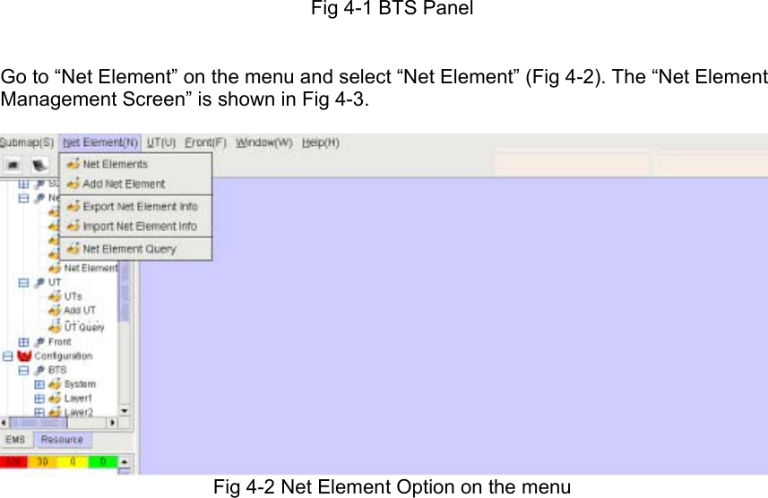
![4. Calibration When BTS is successfully started, some of its initializing data can be configured via EMS client so that BTS is calibrated for normal work. During base station calibration, the inter-antenna phase difference can be measured and the all output power from RFS to antenna can be matched. The calibration should be conducted at least three times to ensure its effectiveness. At least 20 minutes are required for loading new software in RFC. Complete calibration As there may be changes in the system due to temperature and climate changes as well as normal equipment aging in normal operation, the base station must be completely calibrated before power-on after implementation. The calibration is based on the target data set in EMS. In the SkyWay-Mobile BTS system complete calibration is adopted. In complete calibration, calculation is conducted of the power and gain in each antenna to get data for calibrating base station antenna. The calibration result covers calibration data of the eight antennas, current sending and receiving amplitude and phase diagrams of the current calibration results, comparison with history calibration data, etc. In complete calibration a log file will be generated in the “calibration” folder in the “system” of EMS installation folder (standard file location), with standard file name in 154_20061206163046 format. Here,154 is the base station ID and the digits are the time of calibration (year, month, day, hour, minute, second, or YYYYMMDDhhmmss). Calibration method In EMS client computer, open IE and start EMS client GUI in IE address bar; input user name and password in EMS client login window. Click [Resource Management| Network Element Management] and select the bts just added and successfully started. Double click to open BTS panel (Fig 4-1).](https://usermanual.wiki/Solectek/70MOB1/User-Guide-1170071-Page-29.png)
![Fig 4-3: Net Element Management Screen Some basic configurations are needed at this point: Click [System Management-GPS Settings] and select the time zone of the base station in [GMT difference] as shown in Fig 4-4. Click [OK] and the configuration is successful.](https://usermanual.wiki/Solectek/70MOB1/User-Guide-1170071-Page-31.png)
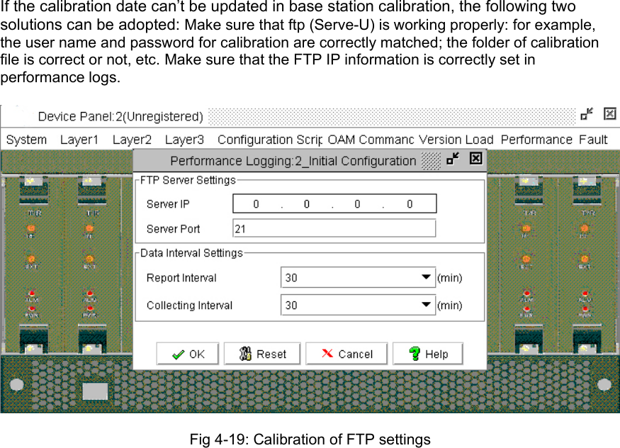
![Fig 4-4: BTS configuration for GPS time Click [OK] in the confirmation window, as shown in Fig 4-5. Fig 4-5: GPS Confirmation Window Enter [System Configuration / Performance Log settings] and fill in [Server IP] with the server IP for performance log uploading and storage. Please make sure that this IP matches the IP address in front-end processor configuration. For other entries, just keep the default value.](https://usermanual.wiki/Solectek/70MOB1/User-Guide-1170071-Page-32.png)
![Fig 4-6: FTP server IP configuration Click [Ok] and the configuration is successful. [L1 Configuration—L1 Configuration]: Antenna mask: Check or uncheck for each one of the 8 antenna masks. Sync Source: “Local” or “GPS”. Please select “GPS” if GPS is connected. Fig 4-7: Antenna Mask and GPS Configuration Click [Ok] and the configuration is successful. Drag the slider to select central frequency used by base station, as shown in Fig 4-8. The values shown for antenna power, receiving sensitivity, cable loss and power splitter loss are factory assigned.](https://usermanual.wiki/Solectek/70MOB1/User-Guide-1170071-Page-33.png)
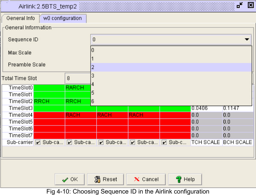
![Fig 4-8: RF Calibration Setting Configuration Click [Ok] and the configuration is successful in the confirmation window (Fig 4-9). Fig 4-9: Calibration setting confirmation window [L2 configuration—Air link] In this screen, the “Fronting Serial ID" supports intra-frequency network. Different numbers should be used for Cell bits;](https://usermanual.wiki/Solectek/70MOB1/User-Guide-1170071-Page-34.png)
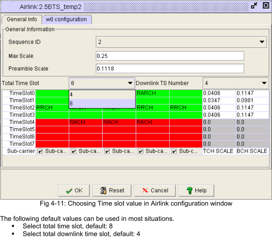
![Fig 4-12: Airlink configuration window Click [Ok] and the configuration is successful. [L2 Configuration| Radio Resource Management Policy Configuration]: Configure the modulation mode, power control and minimum bandwidth. The default, factory assigned values are recommended.](https://usermanual.wiki/Solectek/70MOB1/User-Guide-1170071-Page-37.png)
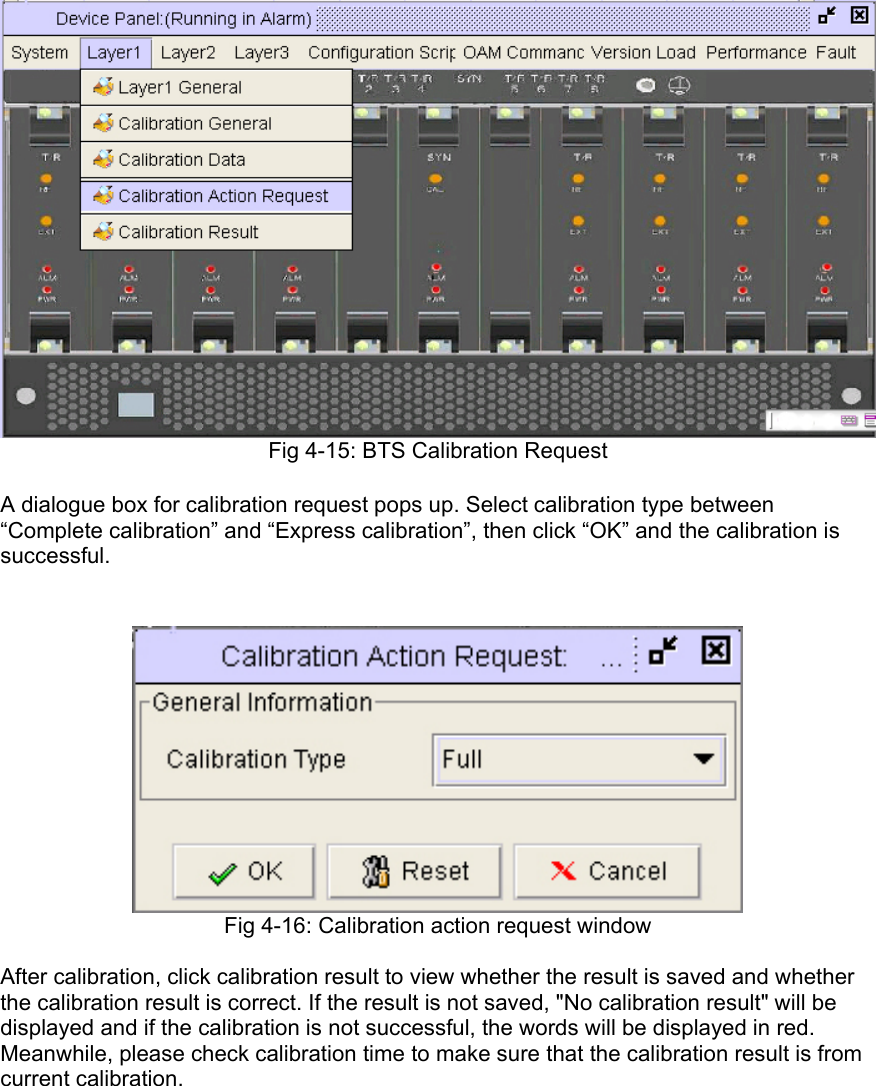
![Fig 4-13: Resource Management Policy Screen Click the base station to be calibrated and select it. Fig 4-14: BTS Calibration Screen Click [L1 Configuration—Calibration Request]](https://usermanual.wiki/Solectek/70MOB1/User-Guide-1170071-Page-38.png)
![Fig 4-17: Calibration Status The calibration process should be executed more than twice. Make sure that the values are relatively stable(+/-3) and there is no “zero” in the result. After the second calibration is conducted, click [Calibration Data] to show the data for second calibration in the window. Fig 4-18: Calibration Data: General Info Calibrate Date](https://usermanual.wiki/Solectek/70MOB1/User-Guide-1170071-Page-40.png)
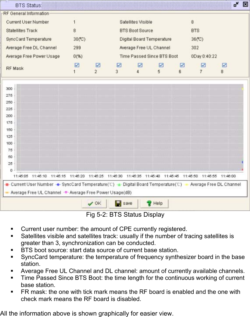
![5. Operating Status Any communication equipments must work within a certain range of temperatures because over-high and over-low temperatures will affect its performance. For SkyWay-Mobile BTS system the working temperature is between 0 and 50 centigrade degree. At the digital panel of the base station there is temperature sensor for real time monitoring of digital chipset board and transmitting detected temperature to EMS network management system. General steps for viewing base station status: Enter the EMS screen and double click the base station to view, then select [OAM Command—BTS System Status] and the corresponding information will pop up. Fig 5-1: Accessing the BTS System Status](https://usermanual.wiki/Solectek/70MOB1/User-Guide-1170071-Page-42.png)
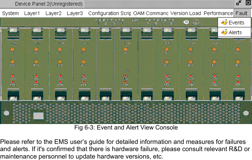
![6. System Alert Similar to any system management system, EMS maintains and stores messages of failures or alerts from the base station, which can be viewed from failure console or alert console. Enter the EMS system and select [Fault—Console—Fault Console] to enter the screen as below. Click the network element to view and click [View] button in the left top and the detailed information of alert will be displayed. Fig 6-1: Failure Console window The operation of alert console is similar with failure console. For a simplified information display, click a tab to sort, for example, sorting by network element. Fig 6-2: Alert console window Enter corresponding network element management and view by selecting the right end [Failure Management—Events/Alerts] in its information panel.](https://usermanual.wiki/Solectek/70MOB1/User-Guide-1170071-Page-44.png)