Somfy Systems DECOFLEX DECOFLEX RTS Switch User Manual decoflex
Somfy Systems DECOFLEX RTS Switch decoflex
User manual
2
1-
- Power: 3V lithium battery, CR 2450 type
o o o o
- Operating temperature: +5 C/41 F to +40 C/104 F
- Range: Up to 65 Ft.
- Fits into standard Decora Wall Plates
Commands are transmitted by radio waves at 433.42 MHz.
Operating Instructions
DECOFLEX RTS SWITCH
DESCRIPTION
PROGRAMMING
The DecoFlex RTS Switch is a wireless radio transmitter compatible with
all Somfy RTS Motors and externally mounted RTS receivers.
This is a low voltage device which does not need to be mounted inside an
electrical box. It can be mounted adjacent to an existing Decora style light
switch or as a stand alone device using the specific SOMFY low voltage
bracket (included).
White: 1810813
Ivory: 1810814
Black: 1810830
A. ADDING A DECOFLEX RTS WALL SWITCH - INITIAL INSTALLATION
IMPORTANT: for initial programming provide power only to the motor or receiver being programmed
1. Set the RTS Receiver or Motor into its Programming Mode (Refer to the installation instructions of the relevant
RTS receiver or motor for this procedure).
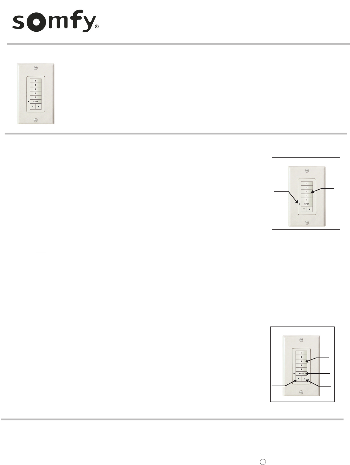
2. Select the Channel to be memorized by pressing the appropriate button. The button will light. Refer to Figure 1.
3. Using a paperclip or similar device, briefly press the programming button (1 sec max) located on the DecoFlex Switch
4. The receiver/motor will confirm the addition of the new DecoFlex Switch in their respective manners.
FIGURE 1
C. REMOVING A DECOFLEX RTS SWITCH FROM THE MOTOR OR RECEIVER’S MEMORY
1. Place the receiver or motor into programming mode by pressing and holding the programming button (for 3 sec.) of a DecoFlex RTS Switch or Telis
Transmitter that has been previously memorized. It should NOT be the one to be removed from memory.
2. The receiver/motor will confirm PROGRAMMING MODE in their respective manners.
3. Select the RTS Switch or Channel to be removed from memory. Press the programming button (1 sec. max.) on the RTS switch.
4. The receiver/motor will confirm the removal of the RTS Switch or Channel in their respective manners.
Ref. No. 2501819 SOMFY SYSTEMS, INC. 3/08
C
SOMFY SYSTEMS, INC.
47 Commerce Drive
Cranbury, NJ 08512
SOMFY CANADA
6315 Shawson Drive, Unit #1
Mississauga, Ontario L5T1J2
SOMFY SYSTEMS, INC. reserves the right to change,
update or improve this document without prior notice.
B. ADDING MULTIPLE DECOFLEX WALL SWITCHES
1. Place the receiver or motor into programming mode by pressing and holding the programming button (for 3 sec.) of a
DecoFlex switch or Telis Transmitter that has been previously memorized. There is no need to access the external receiver
for this operation.
2. The receiver/motor will confirm PROGRAMMING MODE in their respective manners.
3. Select the NEW channel or RTS Switch to be memorized. Press the programming button (1 sec. max.) on the DecoFlex RTS switch.
4. The receiver/motor will confirm the addition of the new RTS Switch or Channel in their respective manners.
Programming
Button
Select the
Channel
3OPERATION
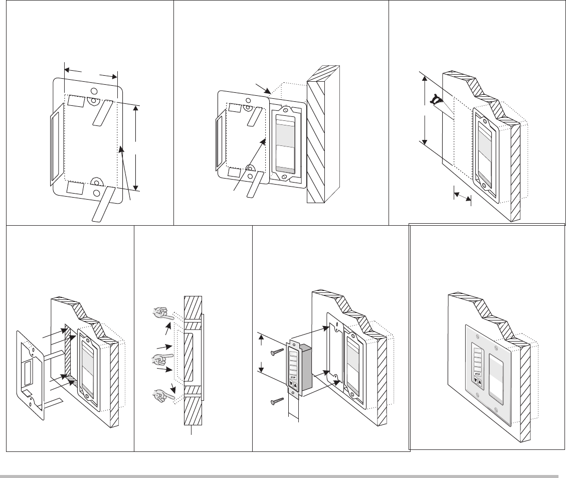
1. Select the channel of the window treatment to be operated by pressing the appropriate button. The button will light.
Refer to Figure 2.
2. To raise the window treatment, press the UP button. Similarly, to lower the window treatment, press the DOWN button.
3. To stop the window treatment at any time, simply press the STOP button.
FIGURE 2
Select the
Channel
STOP
Button
UP
Button
DOWN
Button
BATTERY LIFE
The DecoFlex RTS Switches are powered by a 3V battery (type 2450)
which provides about 25 years operation assuming 4
operations per day. When the battery becomes discharged,
the control LED no longer lights up when a command is
sent, and the command is not carried out.
HOW TO REPLACE THE BATTERY
1. Remove the screws on the back cover of the RTS Switch.
2. Slide the battery out of its holder by pushing it with a screwdriver.
3. Insert the new battery, maintaining its correct polarity.
NOTE: Do not throw the battery in the trash, but dispose of it properly.
INSTALLATION PROCEDURE
MOUNTING METHOD
1. Orient the brackets flat side against
the wall keeping the thin side closest to
and centered with the existing electrical
switch box.
drywall
6. Mount low voltage switch into
bracket, with its edge flush
against electrical switch box.
7. Finish the installation by mounting
a standard double gang Decora
switch cover plate, over both
switches.
5. To keep the bracket in
o
place, bend tabs 90 around
drywall, as tightly as
possible.
4. Insert bracket (as shown) into
hole, keeping the thin side
closest to the existing switch
box, and laying flat on drywall.
2. Align the inside edge of the thin side of the bracket with
the outside edge of the switch box. Then trace the
inside shape (as shown by the dashed line in the
diagram) of the bracket. (sheetrock not shown for clarity)
3. Cut traced opening into drywall. Be careful
not to make the opening larger than
necessary, to ensure a tight fit. Use
dimensions in diagram below. Do not exceed
these dimensions to ensure a proper fit of
the bracket
thin side
of bracket
7
3 /16
7
3 /16
5
1 /8
5
1 /8
1.30
Inside
Edge
Existing Electrical Box
wood 2x4
NOTE: This bracket is designed for an existing electrical box already behind the sheetrock. If a retrofit electrical box was used, it is
recommended to remove the single gang and replace it with a double gang retrofit box.
The special SOMFY low voltage bracket is specifically designed to mount the DecoFlex RTS wall switch next to an existing Decora
light switch with an electrical box already behind the drywall. This bracket differs from other off-the-shelf low voltage brackets
because it is offset on one side. This allows a double gang Decora style cover plate to fit over both switches without installing a
double gang electrical box behind the drywall. It is also possible to mount this bracket as a stand alone low voltage device.
4
5
2.61
This device complies with part 15 of the FCC Rules. Operation is subject to the following two conditions: (i). This device may not cause harmful
interference, and (ii). This device must accept any interference received, including interference that may cause undesired operation.
G
G
G
G
G
G
G
G
G
G
G