Sonic Technology LCT100 Loud and Clear Wireless Auditory Assistance System User Manual LoudandClear Manual 9 11 15
Sonic Technology Products, Inc. Loud and Clear Wireless Auditory Assistance System LoudandClear Manual 9 11 15
user manual

16
Manufactured and Distributed by:
Sonic Technology Products, Inc.
P.O. Box 539
Grass Valley, CA 95945 USA
1-800-247-5548
www.sonictechnology.com
Model LCS110/LCT100/LCR100
Wireless Auditory
Assistance System
Operating Manual
16
Manufactured and Distributed by:
Sonic Technology Products, Inc.
P.O. Box 539
Grass Valley, CA 95945 USA
1-800-247-5548
www.sonictechnology.com
and
Model LCS110/LCT100/LCR100
Wireless Auditory
Assistance System
Operating Manual
®
®
TM
TM
and
Thank you for purchasing the SuperEar® Loudand
Clear FM Transmitter/Receiver Wireless Auditory Assis-
tance System. The SuperEar® LoudandClear is designed
and manufactured to provide clear, crisp stereo sound from
either of two sources: (1) Transmission of normal voice
using the supplied microphone or (2) Transmission of
television, MP3 programming or any other sound source
using the supplied 3.5mm auxiliary cable. The Transmitter
then sends the signal, using one of three pre-selected FM
Radio frequencies, to the Receiver.
The Receiver unit receives the audio signal from up
to 150 feet away and converts it to sound waves that can
be heard through the supplied earbuds and adjusted to the
desired volume.
THE LOUDandCLEAR IS NOT AN FM RADIO!
FOR BEST RESULTS, USE IN LINE-OF-SIGHT
COMMUNICATIONS. SOUND QUALITY WILL
DEGRADE AS WALLS AND OTHER OBSTACLES
MAY INTERFERE WITH SOUND TRANSMISSION.
The LoudandClear is ideal for
• Classroom or Lecture environments
• Worship Services
• Tour Groups
• Hospitals and Long Term Care Facilities
• Television Viewing 2 15
2 15
Thank you for purchasing the SuperEar® Loudand
Clear FM Transmitter/Receiver Wireless Auditory Assis-
tance System. The SuperEar® LoudandClear is designed
and manufactured to provide clear, crisp stereo sound from
either of two sources: (1) Transmission of normal voice
using the supplied microphone or (2) Transmission of
television, MP3 programming or any other sound source
using the supplied 3.5mm auxiliary cable. The Transmitter
then sends the signal, using one of three pre-selected FM
Radio frequencies, to the Receiver.
The Receiver unit receives the audio signal from up
to 150 feet away and converts it to sound waves that can
be heard through the supplied earbuds and adjusted to the
desired volume.
THE LOUDandCLEAR IS NOT AN FM RADIO!
FOR BEST RESULTS, USE IN LINE-OF-SIGHT
COMMUNICATIONS. SOUND QUALITY WILL
DEGRADE AS WALLS AND OTHER OBSTACLES
MAY INTERFERE WITH SOUND TRANSMISSION.
The LoudandClear is ideal for
• Classroom or Lecture environments
• Worship Services
• Tour Groups
• Hospitals and Long Term Care Facilities
• Television Viewing
CONTENTS (LCS110 Only)
1 – FM Transmitter (LCT100)
1 – FM Receiver (LCR100)
1 – Recharging Wall Plug
2 – USB (USB to Mini USB) Recharging Cable
4 – AA Rechargeable Batteries
2 – Belt Clips
1 – Microphone Assembly
1 – Auxilliary (3.5mm jack to 3.5mm jack) Cable
1 – EarBud Assembly
1 – Instruction Manual
USE OF MULTIPLE TRANSMITTERS
AND RECEIVERS
If two transmitters are operating on the same
channel within 200 feet of one another, static and
interference will result. Changing Channels on the
Transmitter and Receiver will resolve this problem.
Important: The SuperEar® LoudandClear is designed
so that the Transmitter can be used with several Receivers
set to the same Channel. Should you desire additional
Receivers for multiple listeners, please contact your
SuperEar® retailer or call, write or e-mail Sonic Technology
Products, Inc.
14 3
Warranty
Sonic Technology Products warrants this product to
be free from defects in workmanship and material under
normal use and conditions for a period of three years from
date of original purchase. Batteries and cables are not
covered by this warranty. Warranty is void if damage is
due to misuse, abuse, negligence, damage caused by heat
or water, or unauthorized modifications or repairs. Sonic
Technology is not liable for consequential damages arising
out of any failure of the equipment to perform as intended.
Sonic Technology shall bear no responsibility or obligation
with respect to the manner or use of equipment sold by it.
Sonic Technology specifically disclaims and negates any
warranty of merchantability or fitness for a particular
purpose of such equipment including, without limitation,
any warranty that the use of such equipment for any
purpose will comply with applicable laws and regulations.
Equipment may be repaired or replaced at the
discretion of Sonic Technology. Should it be necessary to
send in your SuperEar® LoudandClear, return it in a well-
packaged carton and ship postage prepaid to to P.O. Box
539, Grass Valley, CA 95945. Returns made under this
warranty must be accompanied by US$5.00 to handle the
handling and return postage cost.
CONTENTS (LCS110 Only)
1 – FM Transmitter (LCT100)
1 – FM Receiver (LCR100)
1 – Recharging Wall Plug
2 – USB (USB to Mini USB) Recharging Cable
4 – AA Rechargeable Batteries
2 – Belt Clips
1 – Microphone Assembly
1 – Auxilliary (3.5mm jack to 3.5mm jack) Cable
1 – EarBud Assembly
1 – Instruction Manual
USE OF MULTIPLE TRANSMITTERS
AND RECEIVERS
If two transmitters are operating on the same
channel within 200 feet of one another, static and
interference will result. Changing Channels on the
Transmitter and Receiver will resolve this problem.
Important: The SuperEar® LoudandClear is designed
so that the Transmitter can be used with several Receivers
set to the same Channel. Should you desire additional
Receivers for multiple listeners, please contact your
SuperEar® retailer or call, write or e-mail Sonic Technology
Products, Inc.
14 3
Warranty
Sonic Technology Products warrants this product to
be free from defects in workmanship and material under
normal use and conditions for a period of three years from
date of original purchase. Batteries and cables are not
covered by this warranty. Warranty is void if damage is
due to misuse, abuse, negligence, damage caused by heat
or water, or unauthorized modifications or repairs. Sonic
Technology is not liable for consequential damages arising
out of any failure of the equipment to perform as intended.
Sonic Technology shall bear no responsibility or obligation
with respect to the manner or use of equipment sold by it.
Sonic Technology specifically disclaims and negates any
warranty of merchantability or fitness for a particular
purpose of such equipment including, without limitation,
any warranty that the use of such equipment for any
purpose will comply with applicable laws and regulations.
Equipment may be repaired or replaced at the
discretion of Sonic Technology. Should it be necessary to
send in your SuperEar® LoudandClear, return it in a well-
packaged carton and ship postage prepaid to P.O. Box
539, Grass Valley, CA 95945. Returns made under this
warranty must be accompanied by US$5.00 to handle the
handling and return postage cost.
FCC Statement
This device complies with Part 15 of the FCC Rules. Operation
is subject to the following two conditions:
(1) This device may not cause harmful interference, and (2) This
device must accept any interference received, including interference
that may cause undesired operation.
This equipment has been tested and found to comply with the
limits for a Class B digital device, pursuant to part 15 of the FCC Rules.
These limits are designed to provide reasonable protection against
harmful interference in a residential installation. This equipment
generates, uses and can radiate radio frequency energy and, if not
installed and used in accordance with the instructions, may cause
harmful interference to radio communications. However, there is no
guarantee that interference will not occur in a particular installation. If
this equipment does cause harmful interference to radio or television
reception, which can be determined by turning the equipment off and
on, the user is encouraged to try to correct the interference by one or
more of the following measures
—Reorient or relocate the receiving antenna.
—Increase the separation between the equipment and receiver.
—Connect the equipment into an outlet on a circuit different from
that to which the receiver is connected.
—Consult the dealer or an experienced radio/TV technician for
help.
Caution: Any changes or modifications not expressly approved
by the party responsible for compliance could void the user's authority
to operate the equipment.
4 13
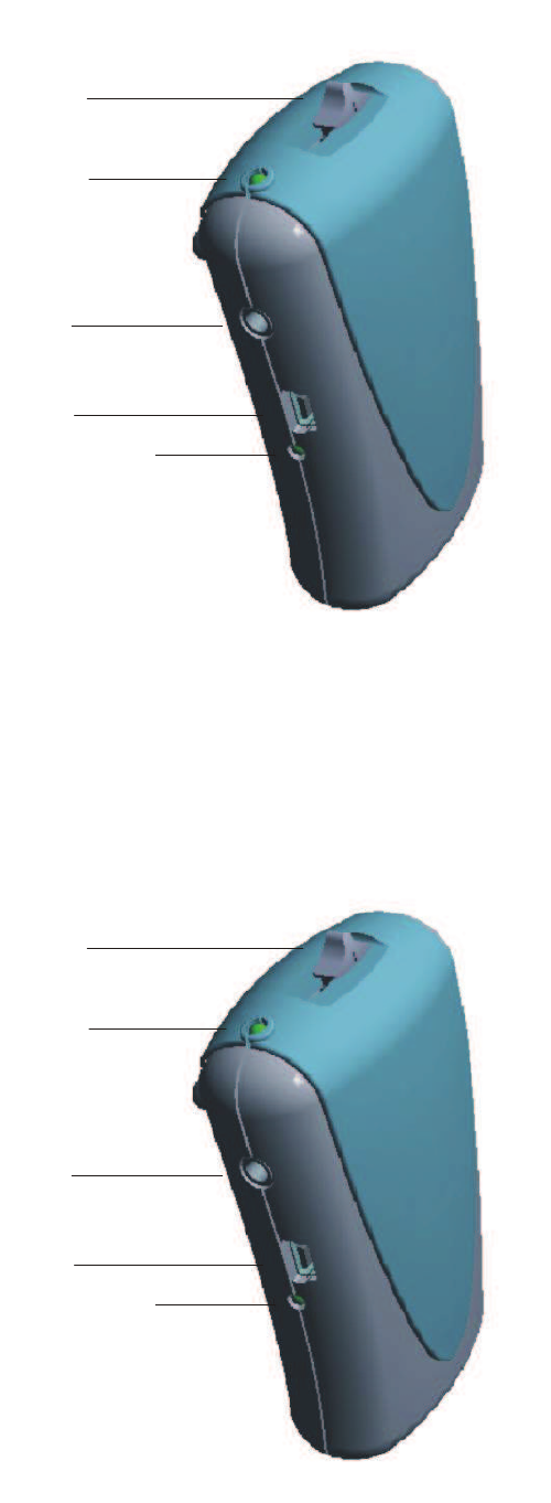
On/Off /Mute
Switch
On/Off/Mute
LED
Microphone
Jack
USB Recharging
Port
Recharging
Indicator LED
TRANSMITTER
On/Mute/Off
On/Off /Mute
Switch
On/Off/Mute
LED
Microphone
Jack
USB Recharging
Port
Recharging
Indicator LED
TRANSMITTER
On/Mute/Off
12 5
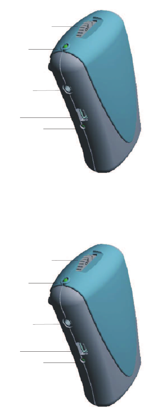
On/Off Volume
Control Wheel
On/Off LED
Headphone/
Ear Bud Jack
USB Recharging
Port
Recharging
Indicator LED
RECEIVER
CARE AND MAINTENANCE
Avoid excessive heat. Do not leave the
Transmitter or Receiver in hot sun or near
other sources of high temperature.
Avoid dropping. The Receiver and
Transmitter may be damaged if dropped.
Keep battery terminals and contacts
clean. Inspect to ensure they are not corroded.
Polish with a pencil eraser to clean.
Remove rechargeable batteries when Receivers
and Transmitters are being stored. Inspect
batteries periodically for leakage.
Use care when removing Ear Buds and
Microphones. Do not pull on wire leads, as
this may loosen connections and cause failure.
12 5
On/Off Volume
Control Wheel
On/Off LED
Headphone/
Ear Bud Jack
USB Recharging
Port
Recharging
Indicator LED
RECEIVER
CARE AND MAINTENANCE
Avoid excessive heat. Do not leave the
Transmitter or Receiver in hot sun or near
other sources of high temperature.
Avoid dropping. The Receiver and
Transmitter may be damaged if dropped.
Keep battery terminals and contacts
clean. Inspect to ensure they are not corroded.
Polish with a pencil eraser to clean.
Remove rechargeable batteries when Receivers
and Transmitters are being stored. Inspect
batteries periodically for leakage.
Use care when removing Ear Buds and
Microphones. Do not pull on wire leads, as
this may loosen connections and cause failure.
611
GETTING STARTED
Battery Placement
Open the battery compartment by sliding the battery
door on the back of the Receiver down and insert the 2
Rechargeable batteries as indicated (+ and – symbols are
molded into the bottom of the battery compartment to
ensure proper placement). Repeat the process for the
Transmitter.
Channel Selection
The SuperEar LoudandClear provides a choice of
three channels, with the Frequency Selector Switch located
inside the battery compartment, above the batteries:
Channel 1 – Far Left Position – 72.2 MHz
Channel 2 - Center Position – 72.8 MHz
Channel 3 – Far Right Position – 75.8 MHz
The Channel Frequency can be easily changed for
the best possible reception. THE SAME CHANNEL
FREQUENCY MUST BE SELECTED FOR BOTH THE
RECEIVER AND THE TRANSMITTER. IF CHANNEL
FREQUENCIES ARE NOT SYNCHRONIZED,
TRANSMISSION AND RECEPTION WILL FAIL.
Channel frequencies are printed on the inside of the
battery compartment door for quick reference.
Belt Clip Installation/Removal
1) Place belt clip over the Battery Compartment
Door, with the top hinge centered between the two anti-
scuff pads and the clips over the retaining slots.
2) Slip the small joint into the slot located above the
Battery Compartment Door.
3) Apply pressure on both sides of the clip until the
clip retainers snap into the slots on the sides of the unit.
4) To remove, flex out one side of the clip retainer,
unsnap from the retaining slot and remove the clip.
Troubleshooting
If noise, distortion or static is present, check that:
• batteries are high quality and fully charged.
• Transmitter and Receiver are set to the same
Channel.
• there are no other Transmitters in the immediate
vicinity transmitting on the same frequency.
• all cables are fully connected.
• the Microphone has not been damaged with
excessive heat or moisture.
• Ear Buds have not been damaged by pulling on the
wires.
If the above steps do not correct the problem,
contact Sonic Technology Products, Inc. for repair or
replacement.
611
GETTING STARTED
Battery Placement
Open the battery compartment by sliding the battery
door on the back of the Receiver down and insert the 2
Rechargeable batteries as indicated (+ and – symbols are
molded into the bottom of the battery compartment to
ensure proper placement). Repeat the process for the
Transmitter.
Channel Selection
The SuperEar LoudandClear provides a choice of
three channels, with the Frequency Selector Switch located
inside the battery compartment, above the batteries:
Channel 1 – Far Left Position – 72.2 MHz
Channel 2 - Center Position – 72.8 MHz
Channel 3 – Far Right Position –75.8 MHz
The Channel Frequency can be easily changed for the
best possible reception. THE SAME CHANNEL FRE-
QUENCY MUST BE SELECTED FOR BOTH THE RE-
CEIVER AND THE TRANSMITTER. IF CHANNEL
FREQUENCIES ARE NOT SYNCHRONIZED,
TRANSMISSION AND RECEPTION WILL FAIL.
Channel frequencies are printed on the inside of the battery
compartment door for quick reference.
Belt Clip Installation/Removal
1) Place belt clip over the Battery Compartment
Door, with the top hinge centered between the two anti-
scuff pads and the clips over the retaining slots.
2) Slip the small joint into the slot located above the
Battery Compartment Door.
3) Apply pressure on both sides of the clip until the
clip retainers snap into the slots on the sides of the unit.
4) To remove, flex out one side of the clip retainer,
unsnap from the retaining slot and remove the clip.
Troubleshooting
If noise, distortion or static is present, check that:
• batteries are high quality and fully charged.
• Transmitter and Receiver are set to the same
Channel.
• there are no other Transmitters in the immediate
vicinity transmitting on the same frequency.
• all cables are fully connected.
• the Microphone has not been damaged with
excessive heat or moisture.
• Ear Buds have not been damaged by pulling on the
wires.
If the above steps do not correct the problem,
contact Sonic Technology Products, Inc. for repair or
replacement.
710
Battery Charging
To charge the batteries in the Receiver or Transmit-
ter, place the rechargeable batteries in the battery compart-
ment as explained above. Plug the recharging Mini USB
end of the Recharging cable into the recharging port. The
other end of the cable with the USB connector may be
either plugged into a USB port on your computer or plugged
into the Recharging Wall Plug, which is in turn plugged into
a 110VAC outlet. Once charging begins, the green Re-
charging Indicator LED will flash until the LED turns to
solid green. This indicates charging is complete.
• Allow Ni-MH Batteries (provided) to charge 12-16
hours for up to 11 hours of useage for Transmitter (102 mA/
hour) and up to 15 hours useage for Receiver (55 mA/hour).
• Excessive charging may reduce the life expect-
ancy and capacity
• The LED light will flash red when the unit is in a
low battery state.
• Charging may be accomplished with the “Power”
either ON or OFF.
• Normal operation may continue while recharging,
if the “Power” mode is ON.
TRANSMITTER OPERATION FOR
TELEVISION/MP3/AUXILLIARY SOUND
TRANSMISSION
Transmitter
1) Install Rechargeable Batteries and charge as
indicated
2) Select Channel Option
3) Plug in the 3.5mm Auxillary Cable Jack into the
Microphone Plug
4) Plug in the other end of the Auxillary Cable into
the Speaker/Aux. Output plug of the television, radio,
computer or MP3 Player.
5) Position the “On/Off/Mute” Switch to the “On”
position. The Green LED will light to indicate the unit is
operating.
Receiver
1) Install Rechargeable Batteries and charge as
indicated
2) Select Channel Option to match Transmitter
Channel
3) Plug in the 3.5mm Headphone or Earbud jack
into the Headphone plug
4) Turn the “On/Off/Volume” Control wheel until it
clicks and the Green LED light goes on. Adjust volume to
preferred level.
89
OPERATION WITHOUT USING
RECHARGEABLE BATTERIES
The SuperEar® LoudandClear was designed to operate
using batteries or 110VAC household current. To power the
Transmitter or Receiver using household current, plug in the
Recharging cable to the unit and the Recharging Wall Plug
just as you would for recharging. Batteries must be in the
unit to operate while plugged into 110v wall plug. If batteries
are not in the unit, it will not operate.
Any rechargeable Ni-MH AA batteries or premium
Alkaline batteries may be used in the SuperEar®
LoudandClear.CAUTION: DO NOT ATTEMPT TO RE-
CHARGE NON-RECHARGEABLE BATTERIES. THIS
MAY DAMAGE THE UNIT.
LED Indicators
Power LED
Green indicates “Power” is ON
Red indicates “Mute” is ON
No light indicates “Power” is OFF
Charging LED
Red Flashing (when “Power” is ON) indicates Low
Battery Status
Green Flashing indicates Batteries are Charging
Solid Green indicates Batteries Fully Charged
No light indicates Batteries are NOT Charging
OPERATION FOR VOICE TRANSMISSION
Transmitter
1) Install Rechargeable Batteries and charge as
indicated
2) Select Channel Option
3) Plug in the 3.5 mm microphone jack into the
microphone plug on the transmitter
4) Clip the microphone to a lapel or collar near the
mouth. HOLDING THE MICROPHONE, AND NOT
CLIPPING IT TO CLOTHING, WILL RESULT IN
SCRATCHY AND DEGRADED SOUND QUALITY.
5) Position the “On/Off/Mute” Switch to the “On”
position. The Green LED will light to indicate the unit is
operating.
6) To disable the transmission momentarily, turn the
Switch to “Mute”. This will cause the transmitter audio
output to cease, without transmitting any static or back-
ground noise. In the “Mute” position, the LED light will
indicate Red.
Receiver
1) Install Batteries and charge as indicated above
2) Select Channel Option to match Transmitter Channel
3) Plug in the 3.5mm Earbud jack into the plug
4) Turn the “On/Off/Volume” Control wheel until it
clicks and the Green LED light goes on. Adjust volume to
preferred level
89
OPERATION WITHOUT USING
RECHARGEABLE BATTERIES
The SuperEar® LoudandClear was designed to operate
using batteries or 110VAC household current. To power the
Transmitter or Receiver using household current, plug in the
Recharging cable to the unit and the Recharging Wall Plug
just as you would for recharging. Batteries must be in the
unit to operate while plugged into 110v wall plug. If batteries
are not in the unit, it will not operate.
Any rechargeable Ni-MH AA batteries or premium
Alkaline batteries may be used in the SuperEar®
LoudandClear.CAUTION: DO NOT ATTEMPT TO RE-
CHARGE NON-RECHARGEABLE BATTERIES. THIS
MAY DAMAGE THE UNIT.
LED Indicators
Power LED
Green indicates “Power” is ON
Red indicates “Mute” is ON
No light indicates “Power” is OFF
Charging LED
Red Flashing (when “Power” is ON) indicates Low
Battery Status
Green Flashing indicates Batteries are Charging
Solid Green indicates Batteries Fully Charged
No light indicates Batteries are NOT Charging
OPERATION FOR VOICE TRANSMISSION
Transmitter
1) Install Rechargeable Batteries and charge as
indicated
2) Select Channel Option
3) Plug in the 3.5 mm microphone jack into the
microphone plug on the transmitter
4) Clip the microphone to a lapel or collar near the
mouth. HOLDING THE MICROPHONE, AND NOT
CLIPPING IT TO CLOTHING, WILL RESULT IN
SCRATCHY AND DEGRADED SOUND QUALITY.
5) Position the “On/Off/Mute” Switch to the “On”
position. The Green LED will light to indicate the unit is
operating.
6) To disable the transmission momentarily, turn the
Switch to “Mute”. This will cause the transmitter audio
output to cease, without transmitting any static or back-
ground noise. In the “Mute” position, the LED light will
indicate Red.
Receiver
1) Install Rechargeable Batteries and charge as
indicated
2) Select Channel Option to match Transmitter Channel
3) Plug in the 3.5mm Earbud jack into the plug
4) Turn the “On/Off/Volume” Control wheel until it
clicks and the Green LED light goes on. Adjust volume to
preferred level