ZF6 6R60 ZIP IN
2016-11-22
: Sonnax Zf6-6R60-Zip-In ZF6-6R60-ZIP-IN 1874 file instruction uploads
Open the PDF directly: View PDF ![]() .
.
Page Count: 11
ZF6HP19/26/32 (Generation 1),
Ford 6R60, 6R75, 6R80,
ZF6HP21/28/34 (Generation 2)
IDENTIFICATION GUIDE
©2016 Sonnax Industries, Inc. ZF6-GEN1-GEN2-ZIP-Identify_A.indd 11-22-16
800-843-2600 • 802-463-9722 • F: 802-463-4059 • www.sonnax.com
1. identify!
Valve Body
Identi cation
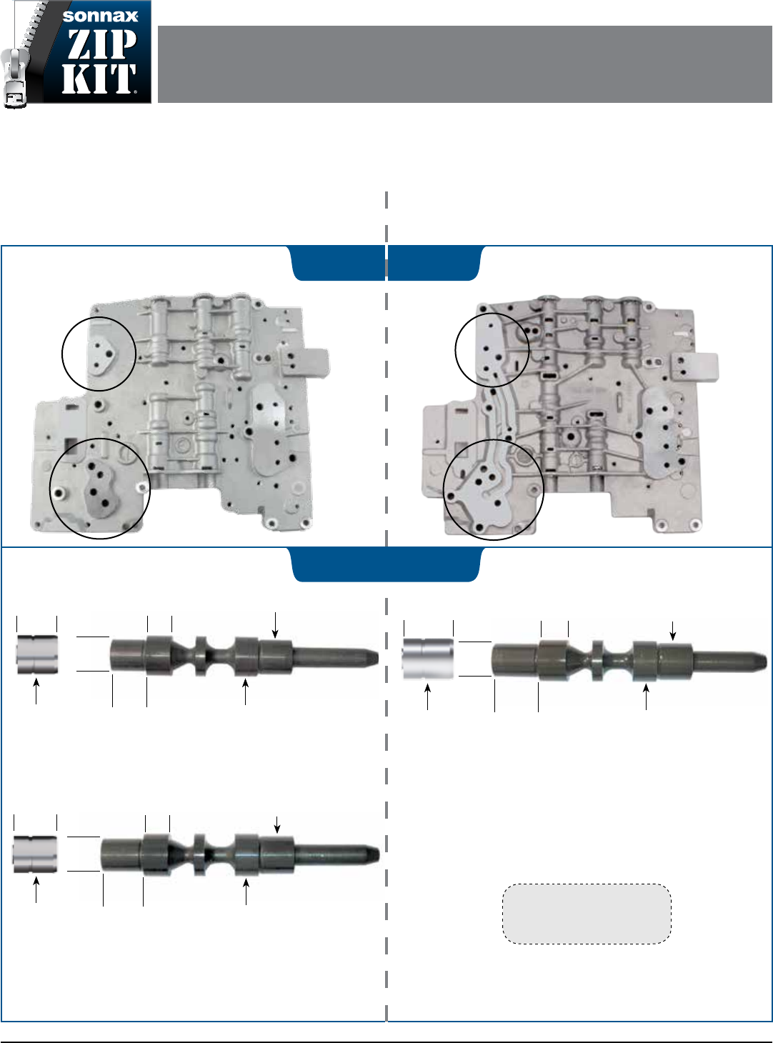
Valve components differ between Generation 1 (ZF6HP19/26/32), Ford 6R60, 6R75, 6R80 and
Generation 2 (ZF6HP21/28/34) valve bodies. Please use this identi cation guide to determine which generation you have
to ensure correct valve kits and components are selected for your rebuild.
NOTE: Some BMW 6 & 7 series with six accumulators have a different
sized pressure regulator valve. This is most commonly seen on the
A053/B053 separator plate applications.
CAUTION: Some valve sizes and locations differ from non-053 plate
Generation 1 units. Reference 053 plate vacumm test guide and
exploded view for details.
.657" dia.
.586" dia.
.511"
dia.
.649"
.378"
.657" dia.
.725"
Pressure Regulator Valves and Sleeves
Cannot Be Interchanged
.629" dia.
.562" dia.
.511"
dia.
.725"
.418"
.629" dia.
.804"
.629" dia.
.550" dia.
.495"
dia.
.568"
.378"
.629" dia.
.645"
Different Sized Pressure Regulator
Valves and Sleeves
2nd Generation Case Side
Includes 21, 28 & 34
1st Generation Case Side
Includes 19, 26 & 32
Verify OE dimensions
indicated in order to select
correct Sonnax parts.
2. VERify!
Generation 1 (ZF6HP19, 26 & 32),
Ford 6R60, 6R75, 6R80 Generation 2 (ZF6HP21, 28 & 34)
Generation 1 (ZF6HP19, 26 & 32),
with 053 Separator Plate
ZF6HP19, ZF6HP26, ZF6HP32 (Gen. 1),
FORD 6R60, 6R75, 6R80 ZIP KIT
PART NUMBER ZF6-6R60-ZIP QUICK GUIDE
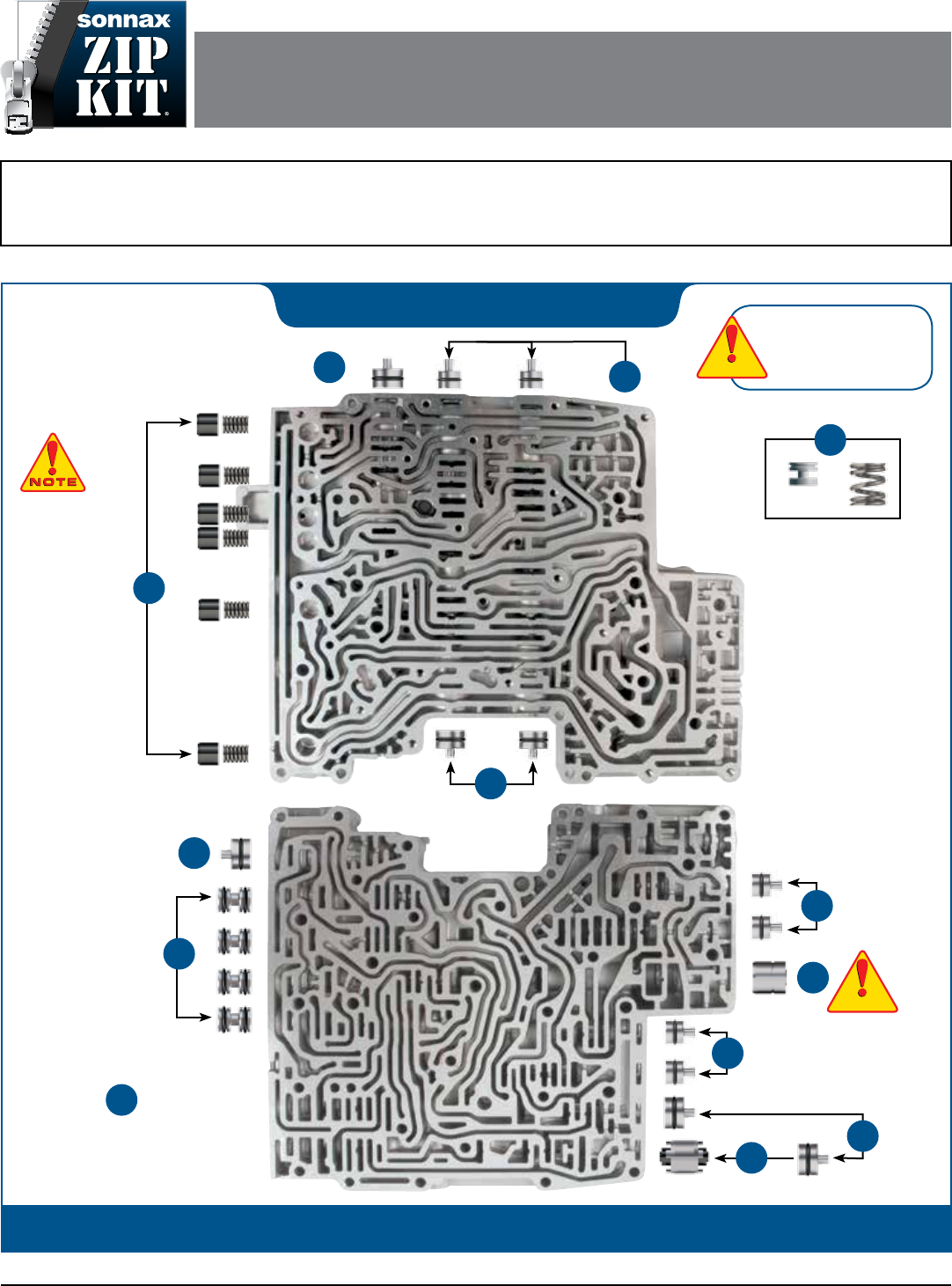
Parts are labeled here in order of installation. See other side of sheet for details on Zip Kit contents.
©2016 Sonnax Industries, Inc. ZF6-6R60-ZIP-Guide_G 11-22-16
800-843-2600 • 802-463-9722 • F: 802-463-4059 • www.sonnax.com Page 1
installation Diagram
In addition to general rebuilding tips and technical information, the technical booklet included in this kit contains vacuum testing
and additional repair options for higher mileage units or for repairing specific complaints which are beyond the scope of this kit.
Valve Body
Identication
This Zip Kit ZF6-6R60-ZIP is designed for ZF6HP19, ZF6HP26, ZF6HP32 (Generation 1) units without an 053 separator plate,
and Ford 6R60, 6R75, 6R80 applications only.
A separate Zip Kit ZF6-GEN2-ZIP is available for ZF6HP21, ZF6HP28, ZF6HP34 (Generation 2), and ZF6-053-ZIP is available
for ZF6HP19, ZF6HP26, ZF6HP32 (Generation 1) units with an 053 separator plate. See separate identication guide for details.
Lower Valve Body
Upper Valve Body
8
7
Solenoid O-Rings
Not Shown Here
See Page 3 of Booklet
Large
4
4
Large
6
Small
5
4
3
1
Large
Small
Small
5
5
Large
4
Verify valve body is a
Generation 1 model. See
separate identication
guide for details.
CAUTIONCAUTION
CAUTIONCAUTION
2
NOTE: Some
6R60 and 6R80
models only have
2 accumulators.
CAUTIONCAUTION
CAUTIONCAUTION
ZF6HP19, ZF6HP26, ZF6HP32 (Gen. 1),
FORD 6R60, 6R75, 6R80 ZIP KIT
Quick Guide
©2016 Sonnax Industries, Inc. ZF6-6R60-ZIP-Guide_G 11-22-16
800-843-2600 • 802-463-9722 • F: 802-463-4059 • www.sonnax.com Page 2
Step Replace OE Sleeve
CAUTION: Verify OE pressure regulator valve and sleeve
measurements. See separate Identication Guide for details.
Packaging Pocket 1
• Sleeve (.629" dia. x .645" length)
Step Replace OE Sleeve & Valve
Packaging Pocket 2
• Valve
• Sleeve
Step Replace Internal
OE End Plugs
Packaging Pocket 3
• Internal End Plugs (4)
• O-Rings (11) 3 extra
Step Replace Large OE
End Plugs
Packaging Pocket 4
• End Plugs, Large (6)
• O-Rings, Large (9) 3 extra
Step Replace Small OE
End Plugs
Packaging Pocket 5
• End Plugs, Small (6)
• O-Rings, Small (9) 3 extra
1
CAUTIONCAUTION
CAUTIONCAUTION
2
3
4
5
Step Replace OE Pistons
Packaging Pocket 6 Patent No. 8,794,108
• Accumulator Pistons (6)
• Matching Springs (6)
NOTE: Some 6R60 and 6R80 models only have 2 accumulators.
Step Replace OE
Solenoid O-Rings
Packaging Pocket 7
• O-Rings, Size 10.5 x 2mm thick, Smaller (8)
• O-Rings, Size 13 x 2mm thick, Larger (7)
Packaging Pocket 8
• O-Rings, Size 13.5 x 2mm thick (4)
Packaging Pocket 9
• O-Rings, Size 14.5 x 1.5mm thick (5)
Packaging Pocket 10
• O-Rings, Size 14.5 x 2mm thick (3)
Packaging Pocket 11
• O-Ring, OR-014, Smaller (2)
• O-Ring, OR-016, Larger (2)
NOTE: See page 3 in the technical booklet included with this Zip Kit for
details on replacement solenoid O-ring locations.
Step Vacuum Testing
Packaging Pocket 12
• Testing Spring
• Testing End Plug
NOTE: See page 4 in the technical booklet included with this Zip Kit for
instructions on how to vacuum test with these two parts.
6
7
8
Zip Kit Contents & Installation Steps
Cautions
Electronics
Do not use an ohm meter with more than .6 voltage supply. e TCM is capable
of limited solenoid adaptation without reprogramming. After any service, resetting
adapts/clearing KAM is suggested. In many instances, solenoids can be replaced with
new OE or with qualied used. Original solenoids, if reused, should be returned to
their same location due to a learned ow rate by the TCM. Make every eort to
avoid mixing up the solenoids.
It is not advised to attempt circuit testing through the 16-pin connector. Check the
solenoid resistance (5.0 ohms at 20C/68F) with the circuit board removed.
Visual Identication
e ZF6 has two generations:
• 2002–2005 ZF6HP19, ZF6HP26, ZF6HP32 = Generation 1
• 2006-later ZF6HP21, ZF6HP28, ZF6HP34 = Generation 2
e 19, 26 and 32 of Generation 1 ZF6 units refer to the sequentially larger amounts
of torque capacity. In 2006, the mechatronic was upgraded to increase oil ow,
which reduced the duration of the shift. ese units became known as Generation 2,
and were given the numbers 21, 28 and 34. e photos on the separate identication
guide show how to identify and verify the valve body as a Generation 1 or Generation 2
version with the updated solenoids.
Within both vintages, there is an “M” version for the manual valve and an “E” solenoid
controlled manual valve. e “E” version in both the early and late generations will
have two additional solenoids, for a total of 9.
Technical Tips
2-1 Clunk (6R60 & 6R80 Only)
Ford 6R60 and 6R80 units commonly display a
2-1 down shift clunk. In mid-2010, a manufac-
turing change was made eliminating this clunk
on models produced after mid-2010. However,
in mid-2010 and earlier models, there is NO known OE or aftermarket remedy.
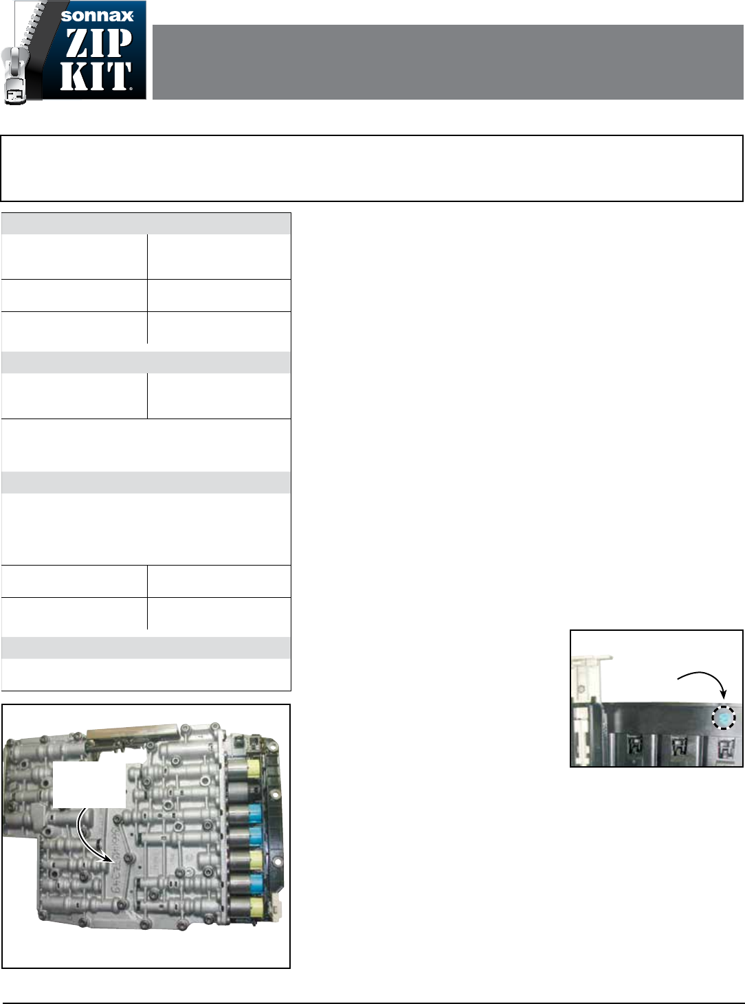
Reprogramming
As indicated on the photo (Figure 1) an engraved number identies this mechatronic
as a service unit. is exchange unit may also have a blue paint dot, (Figure 2) on
the solenoid end of the plastic frame, next to the bar code part number. is blue
dot indicates it is NOT programmed and that the unit must be ashed with vehicle
application prior to installation.
A white dot in the same area indicates the unit HAS been programmed without the
transmission.
A pin dot identication in the same area with a fth, sixth or seventh digit of 128
indicates this is a NEW unit, not a serviced mechatronic.
Torque Specifications
Mechatronic-to-Case or
Valve Body Halves Bolts
8Nm/71 in-lb
Metal Oil Pan to Case
14Nm/10 ft-lb
Plastic Oil Pan to Case
10Nm/89 in-lb
Pump Bolts to Case
10Nm/89 in-lb
Output Shaft Flange Nut
60Nm/44 ft-lb
Clearance & Endplay
Rear Unit Endplay
(flanged output)
0.15-0.35mm/.006-.013"
Input Shaft Endplay
0.2-0.4mm/.008-.015"
Clutch clearance and material is critical (refer to OE
clutch travel specifications). These have fluid balanced
clutch pistons.
Fluid
Ford 6R60 extension housing has an allen head fill
plug and/or the front corner of the case has a hex head
fill plug. A dipstick lives within this plug.
Note: The thermal element must open (88C, 190F) to
purge the cooler before verifying the fluid level!
Complete Fill Required
9.5 qt./9 ltr.
Service Fill Approx.
4.2 qt./4 ltr.
Ford Fluid
XT-6-QSP, Mercon SP
ZF Fluid S671 090 0255-
Shell M-1375.4
Drive-Cycle Relearn
Ford requires six light throttle up and coastdown shift
cycles (after obtaining 80C/175F) for a partial relearn.
Figure 1
Engraved
Number I.D.
Location
OE Serviced Valve Body
Figure 2
Blue Paint
Dot
Location
Valve Body
Identication
This Zip Kit ZF6-6R60-ZIP is designed for ZF6HP19, ZF6HP26, ZF6HP32 (Generation 1) units without an 053 separator plate,
and Ford 6R60, 6R75, 6R80 applications only.
A separate Zip Kit ZF6-GEN2-ZIP is available for ZF6HP21, ZF6HP28, ZF6HP34 (Generation 2), and ZF6-053-ZIP is available
for ZF6HP19, ZF6HP26, ZF6HP32 (Generation 1) units with an 053 separator plate. See separate identification guide for details.
ZF6HP19, ZF6HP26, ZF6HP32 (Gen. 1),
FORD 6R60, 6R75, 6R80 ZIP KIT
PART NUMBER ZF6-6R60-ZIP TECHNICAL BOOKLET
©11-22-16 Sonnax Industries, Inc. ZF6-6R60-ZIP-Booklet_G 11-22-16
800-843-2600 • 802-463-9722 • F: 802-463-4059 • www.sonnax.com Page 1
11-22-16 ZF6-6R60-ZIP-Booklet_G ©2016 Sonnax Industries, Inc.
Page 2 800-843-2600 • 802-463-9722 • F: 802-463-4059 • www.sonnax.com
TIME TESTED • INDUSTRY TRUSTED
ZF6HP19, ZF6HP26, ZF6HP32 (Gen. 1),
FORD 6R60, 6R75, 6R80 ZIP KIT Technical Booklet
Technical Tips (continued)
Transmission Specications & Reassembly Tips
ZF suggests the body-to-case, pump in/out adapter seal be replaced on every valve
body R-R (Figure 3). e overall seal height on these vary depending on application.
Make sure you have the correct size.
ere are four mechatronic-to-case center support seals. e longest (blue) resides
next to the manual linkage, medium (green) next to it. e two shortest ones (black)
are furthest from the linkage (Figure 3).
e Ford 6R60 thermal bypass valve lives in the front corner, between case and valve
body. e spring installs into the case, followed by the thermal valve – small tip end up.
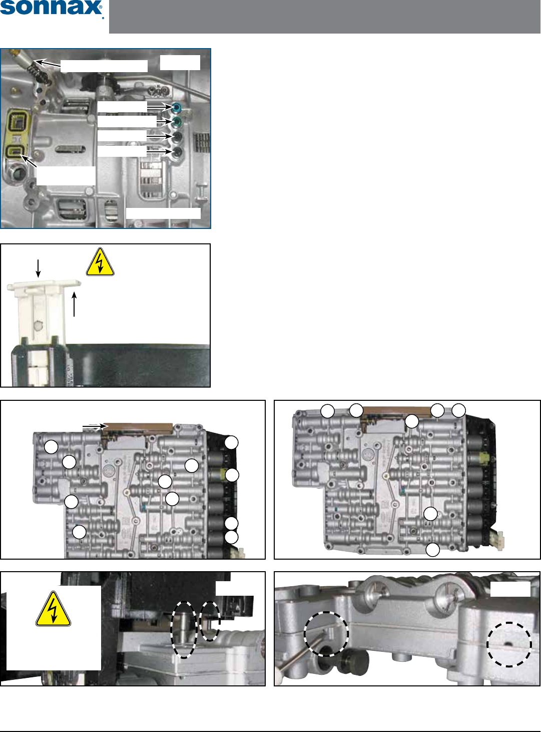
Zip Kit Instructions
1. Valve Body Removal from Case
a. Press release tab and lift connector retainer (Figure 4).
b. Pull connector sleeve out of case.
c. Remove 10 or 11 bolts to drop valve body from case (Figure 5).
2. Valve Body Disassembly
a. Remove seven bolts to remove TCM from valve body (Figure 6).
b. Remove TCM (Figure 7).
c. Pry valve body halves from separator plate where indicated (Figure 8).
ESD (Electro-Static Discharge)
WARNING! Do NOT touch pins
or contacts! Wear ground strap
when handling TCM.
Connector
Retainer
Release Tab
Figure 4
M-Circuit = shown E-Circuit = same AWD unit = extra bolt, #11
10
1
8
9
2
6
4
7
5
3
11
Circuit I.D Location
Figure 5
Figure 8
Blue, Long
Green, Medium
Black, Short
Black, Short
Thermal Bypass Valve
Pump Adapter
Seal
Transmission Case
Figure 3
Figure 7
ESD (Electro-Static
Discharge) WARNING!
Wear ground strap
when handling TCM.
12
6
4 5
3Figure 6
7
©2016 Sonnax Industries, Inc. ZF6-6R60-ZIP-Booklet_G 11-22-16
800-843-2600 • 802-463-9722 • F: 802-463-4059 • www.sonnax.com Page 3
ZF6HP19, ZF6HP26, ZF6HP32 (Gen. 1),
FORD 6R60, 6R75, 6R80 ZIP KIT Technical Booklet
3. Installation
Install Zip Kit parts as shown on diagram of separate
quick guide sheet included in this Zip Kit. e loca-
tions of the replacement solenoids O-rings are shown at
left (Figure 13). For additional solenoid information see
Solenoid O-Ring Sizes charts and Solenoid Function
charts (Figures 14–17) on page 8 of this booklet.
Sonnax recommends vacuum testing critical wear
areas not covered by this kit to determine whether
additional Sonnax parts are required (see pages 4–5).
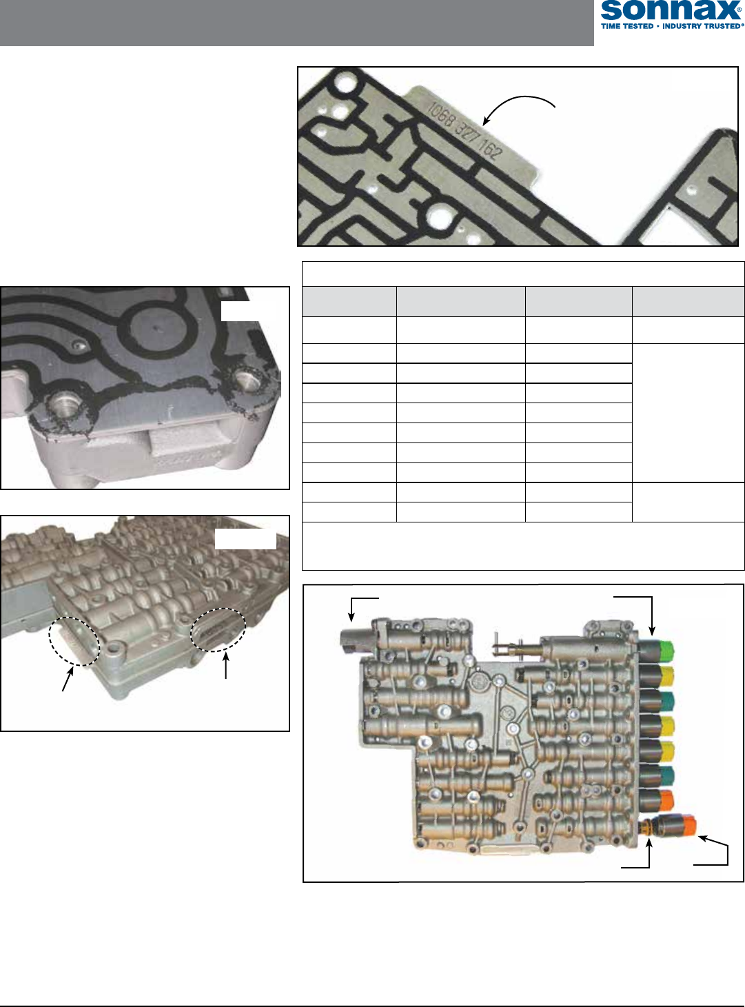
2. Valve Body Disassembly
(continued)
NOTES: The separator plate has a bonded gasket which
may delaminate during disassembly (Figure 9). If any
damage or delamination to the gasket is present, a new
Sonnax separator plate should be used.
These separator plates are specifically calibrated, requiring
either the OE valve body code or an identification number
stamped on original plate (Figures 10 & 11) for reorder.
See Sonnax application chart for cross-reference numbers
(Figure 12).
Figure 13
NOTE: O-ring sizes vary depending upon solenoid, location, make, model and generation
version. Included in this Zip Kit are 31 standard replacement-size O-rings for the various
solenoids. It is recommended to verify the size of the replacement O-ring by physically
comparing it against the OE. The chart (Figure 14, page 8) provides some general guidance.
MV3
EDS6
MV1 (EDS7
on Gen2)
EDS4
EDS5
EDS3
EDS2
EDS1
MV2
These two solenoids on E-Shift versions only.
Snout
Connector
End
Figure 9
Original Number
Stamped on OE Plate
OE Valve
Body Code
Figure 10
Figure 11
Original Number
Stamped on OE Plate
Valve Body Separator Plate Application Chart
OE Valve
Body Code
Number Stamped on
Original Plate
Order Sonnax
Part Number
Valve Body
Generation
E510F 6L2P-7Z490-FC or
6L2P-7Z490-FB 95740-510** Ford 6R60
A035/B035 1068-327-141 95740-035
ZF6HP19/26/32
(Generation 1)
A036/B036 1068-327-145 95740-051*
A046/B046 1068-327-162 95740-046
A047/B047 1068-327-163 95740-047
A051/B051 1068-327-179 95740-051*
A052/B052 1068-327-180 95740-052
A053/B053 1068-327-189 95740-053
A063/B063 1068-327-210 95740-063 ZF6HP21/28/34
(Generation 2)
A065/B065 1068-327-224 95740-065
*Sonnax valve body plate 95740-051 is a direct replacement for both OE valve body codes A036/B036
and A051/B051, due to supersession by ZF.
**Sonnax valve body plate 95740-510 is a replacement for OE plates stamped with part number
6L2P-7Z490-FB or 6L2P-7Z490-FC.
Figure 12
11-22-16 ZF6-6R60-ZIP-Booklet_G ©2016 Sonnax Industries, Inc.
Page 4 800-843-2600 • 802-463-9722 • F: 802-463-4059 • www.sonnax.com
TIME TESTED • INDUSTRY TRUSTED
ZF6HP19, ZF6HP26, ZF6HP32 (Gen. 1),
FORD 6R60, 6R75, 6R80 ZIP KIT Technical Booklet
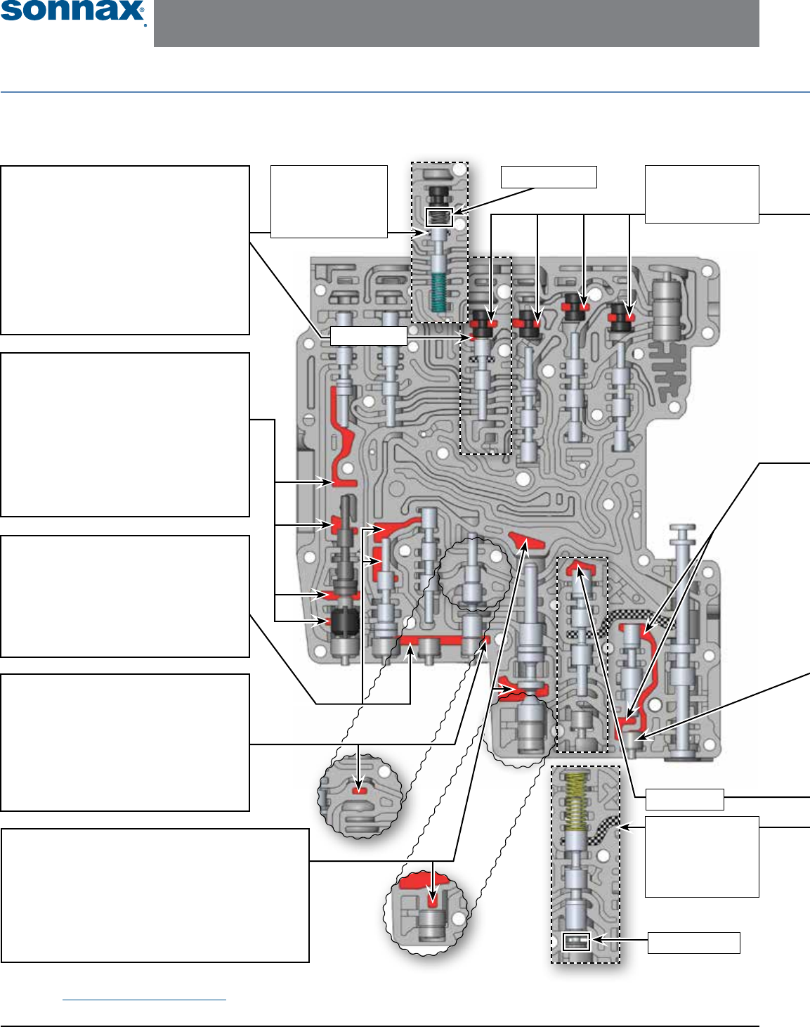
Critical Wear Areas & Vacuum Test Locations
NOTE: OE valves are shown in rest position and should be tested in rest position unless otherwise indicated. Test locations are pointed to with an
arrow. Springs are not shown for visual clarity. Low vacuum reading indicates wear and Sonnax parts noted for replacement.
Lower Valve Body • Jaguar ZF6HP26, M-Shift Shown Here
Test 1: In Rest
Test 2: Test this port
with valve in regulating
position. Block valve
inboard with enclosed
testing spring.
Test 2: Test this port
with valve in inverted
position. Hold valve
and spring in place
with enclosed testing
end plug.
Test 1: In Rest
Use Test End Plug
Use Testing Spring
Solenoid Pressure
Regulator Valve
• Soft Shifts, poor line rise
• High line pressure during stall test
• Loss of 1-2 or 4-5 upshift
• Delayed forward/reverse engagement
• 5-4 or 4-3 Flare
• Gear ratio codes
Replace with Sonnax Part No.
95740-17K Requires F-95740-TL17 & VB-FIX
Clutch A Control Pressure
Regulator Valve
• Delayed/Harsh forward engagement
• Flare/Neutral on 5-4 downshift
• No 4-5 Shift
• VFS 1/A solenoid control code
Replace with Sonnax Part Nos.
95740-09K Oversized Clutch A Control Valve Kit
95740-21K* Clutch A Control Boost Valve Kit
95740-09K: Requires F-95740-TL8 & VB-FIX
Clutch E Control
Pressure Regulator Valve**
• Bumpy 1-2 upshift
• 2-1 Downshift flare or neutral
• EDS 3 control code
Replace with Sonnax Part No.
95740-08K** Requires F-95740-TL8 & VB-FIX
Bypass Clutch Control
Regulator Valve
• Converter overheat & low release pressure
• Excessive TCC slip/cycling RPM
• Firm up/downshifts
• TCC related codes
Replace with Sonnax Part No.
95740-13K Requires F-95740-TL13 & VB-FIX
Main Pressure Regulator Valve**
• Delayed/No reverse • Poor shift quality
• Slip forward/reverse • Erratic or high/low line pressure
Replace with Sonnax Part Nos.
95740-01K OR 95740-78K Oversized PR Valve Kits
95740-03* OR 95740-79* Pressure Regulator Sleeves
95740-01K Requires F-95740-TL & VB-FIX
95740-78K Requires F-95740-TL78 & VB-FIX
Vacuum test these
plugs at the retainer
slot. This checks both
diameters of the plug.
** NOTE: ZF6HP19/26/32 (Gen. 1) applications with an 053 separator plate have significantly different valve lineups and locations.
Reference Vacuum Test Guide for 053 plate for test locations and replacement parts.
©2016 Sonnax Industries, Inc. ZF6-6R60-ZIP-Booklet_G 11-22-16
800-843-2600 • 802-463-9722 • F: 802-463-4059 • www.sonnax.com Page 5
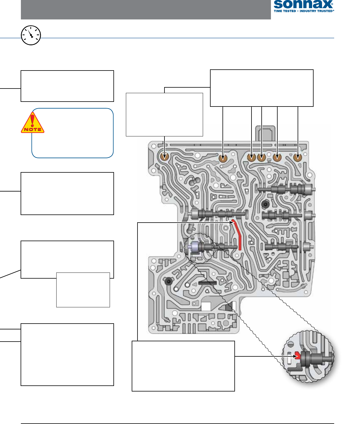
ZF6HP19, ZF6HP26, ZF6HP32 (Gen. 1),
FORD 6R60, 6R75, 6R80 ZIP KIT Technical Booklet
*Part numbers with an asterisk (*) are included in this Zip Kit. Other part numbers are available separately.
*** 6R80 applications, 2012-later, have a different design clutch D1 pressure regulator valve. Sonnax part 95740-08K will not work in that application.
A quick identification of this valve body is lack of clutch D2 latch valve.
Accumulator Pistons
• Firm up/downshifts & harsh engagement
• Erratic EDS solenoid control/EDS codes
Replace with Sonnax Part No.
95740-15K* Patent No. 8,794,108
OE accumulator pistons should be flush
with or approximately .030" lower than
the casting surface. It is common for
the rubber insert to lose tension.
Each of these pistons can be vacuum
tested from the exhaust hole on the
opposite side of the casting.
Clutch D1 Control
Pressure Regulator Valve***
• Bumpy 1-2 upshift
• 2-1 Downshift flare or neutral
• EDS 3 control code
Replace with Sonnax Part No.
95740-08K Requires F-95740-TL8 & VB-FIX
For specific vacuum test information, refer to individual part instructions included in kits and available at www.sonnax.com.
20
25
15
0
10
5
30
VACUUM
TEST
Converter Release
Regulator Valve
• Excessive TCC slip RPM
& related codes
• Harsh lockup apply & release
• Harsh downshifts
• Converter overheat
Replace with Sonnax Part No.
95740-05K Requires F-95740-TL5 & VB-FIX
Upper Valve Body • Jaguar ZF6HP26, M-Shift Shown Here
End Plugs
Inconsistent shift quality
Replace with Sonnax Part No.
95740-25K*
Lubrication Control Valve
• Excessive cooler pressure (ruptured
hoses or cooler)
• Bushing and/or planet overheat
Replace with Sonnax Part No.
95740-11K Requires F-95740-TL11 & VB-FIX
End Plugs,
Multiple Locations
Inconsistent shift quality
Replace with Sonnax Part No.
95740-19K* Can be vacuum tested from
the outside bore face. Use
the large rubber cone
found in many hand pump
kits, or drill a hole through
a rubber ball.
There are numerous OE circuit/
worm-track configurations. They
are make, model, generation
and E- vs M-Shift dependent.
Use the illustrated port loca-
tions as a guide for identifying
specific valve spools to vacuum test
on alternate circuit configurations.
***
11-22-16 ZF6-6R60-ZIP-Booklet_G ©2016 Sonnax Industries, Inc.
Page 6 800-843-2600 • 802-463-9722 • F: 802-463-4059 • www.sonnax.com
TIME TESTED • INDUSTRY TRUSTED
ZF6HP19, ZF6HP26, ZF6HP32 (Gen. 1),
FORD 6R60, 6R75, 6R80 ZIP KIT Technical Booklet
110
111
112
115116
106
108
107 105
104
103
102
113
115116
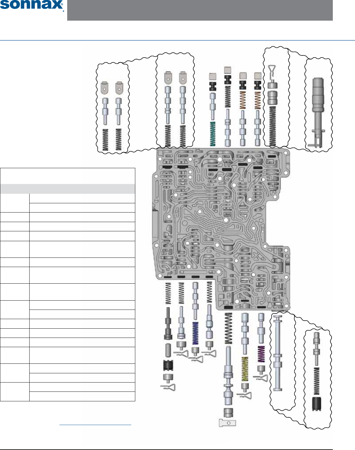
Lower Valve Body Descriptions
I.D No. Description
101 Manual Valve (M-Shift)
Parking Lock Valve (E-Shift)
102 Lubrication Control Valve
103 Converter Release Regulator Valve
104 Main Pressure Regulator Valve
105 Bypass Clutch Control
Regulator Valve
106 Clutch E Latch Valve
107** Clutch E Control Pressure
Regulator Valve
108 Clutch A Control
Pressure Regulator Valve
109 Delay Accumulator Piston (M-Shift)
Park Lock Cylinder (E-Shift)
110 Solenoid Multiplex Valve
111 Drive Enable Valve
112 Clutch D1 Latch Valve
113 Solenoid Pressure
Regulator Valve
115 Clutch B Latch Valve (M-Shift)
Clutch B Latch Valve (E-Shift)
116 Clutch A Latch Valve (M-Shift)
Clutch A Latch Valve (E-Shift)
OE Exploded View
Lower Valve Body • Jaguar ZF6HP26, M-Shift Shown Here
NOTE: Depending upon vehicle application, the OE springs shown
may not be present.
** NOTE: ZF6HP19/26/32 (Gen. 1) applications with an 053
separator plate have significantly different valve line-ups
and locations. Reference Vacuum Test Guide for 053 plate
for test locations and replacement parts.
E-Shift
M-Shift 109
M-Shift
E-Shift
109
101
M-Shift
E-Shift
101
©2016 Sonnax Industries, Inc. ZF6-6R60-ZIP-Booklet_G 11-22-16
800-843-2600 • 802-463-9722 • F: 802-463-4059 • www.sonnax.com Page 7
ZF6HP19, ZF6HP26, ZF6HP32 (Gen. 1),
FORD 6R60, 6R75, 6R80 ZIP KIT Technical Booklet
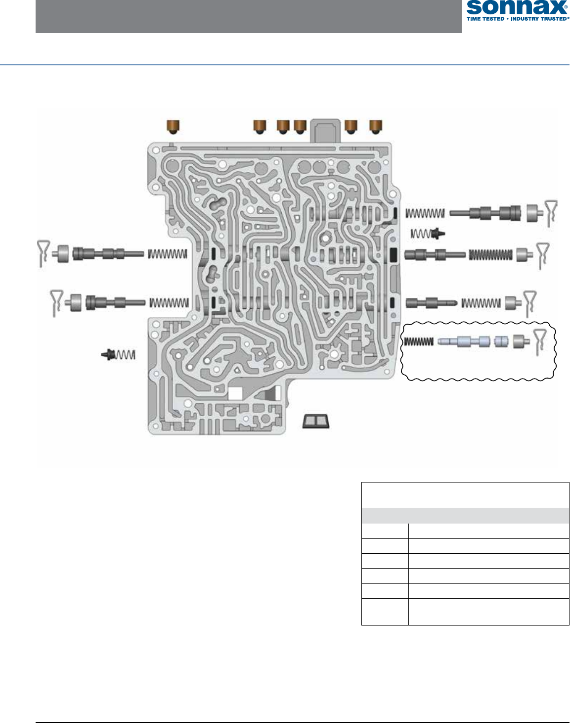
Upper Valve Body • Jaguar ZF6HP26, M-Shift Shown Here
204
203
202
201
Drainback
Clutch Exhaust
Upper Valve Body Descriptions
I.D. No. Description
201 Clutch B Regulator Valve
202 Clutch D2 Regulator Valve
203 Clutch D2 Latch Valve
203A Position D Valve
204 Clutch C Regulator Valve
205 Clutch D1 Control
Pressure Regulator Valve
Accumulator
Pistons
205
203A
E-Shift Only
11-22-16 ZF6-6R60-ZIP-Booklet_G ©2016 Sonnax Industries, Inc.
Page 8 800-843-2600 • 802-463-9722 • F: 802-463-4059 • www.sonnax.com
TIME TESTED • INDUSTRY TRUSTED
ZF6HP19, ZF6HP26, ZF6HP32 (Gen. 1),
FORD 6R60, 6R75, 6R80 ZIP KIT Technical Booklet
Technical Tips (continued from page 3)
TECH TIP: Solenoids in these
units (especially the more
active solenoids) commonly
malfunction, leading to
hydraulic control trouble, requiring
solenoid replacement in many cases.
TECH
TIP!
TECH
TIP!
Ford Solenoid Function
Connector or Snout
Color Location Output Resistance at
68˚F (20˚C) Function
Ford 2007–2009: 6R60
Brown SSA, SSC, TCC, VFS1, VFS3, VFS6 0 psi (0 bar) at 0 mA 5.05 ohms 1 – A Clutch; 3 – C Brake; 6 – TCC
Black SSB, SSD, PCA, VFS2, VFS4, VFS5 67 psi (4.6 bar) at 0 mA 5.05 ohms 2 – B Clutch; 4 – D & E Clutch; 5 – EPC
Cream SSE/SS1 Open/Closed 11.5 ohms Solenoid Multiplex/Drive Enable Valve
Ford 2010 – Later: 6R60/6R80
Brown SSA, SSC, TCC, VFS1, CFS3, VFS6 0 psi @ 0 mA 5.05 ohms 1 – A Clutch; 3 – C Brake; 6 – TCC
Black SSB, SSD, PCA, VFS2, VFS4, VFS5 67 psi (4.6 bar) at 0 mA 5.05 ohms 2 – B Clutch; 4 – D & E Clutch; 5 – EPC
Cream (2010–2011) SSE/SS1 Open/Closed 11.5 ohms Solenoid Multiplex/Drive Enable Valve
Gray (2012–Later) SSE/SS1 Open/Closed 18 ohms Solenoid Multiplex/Drive Enable Valve
Figure 17
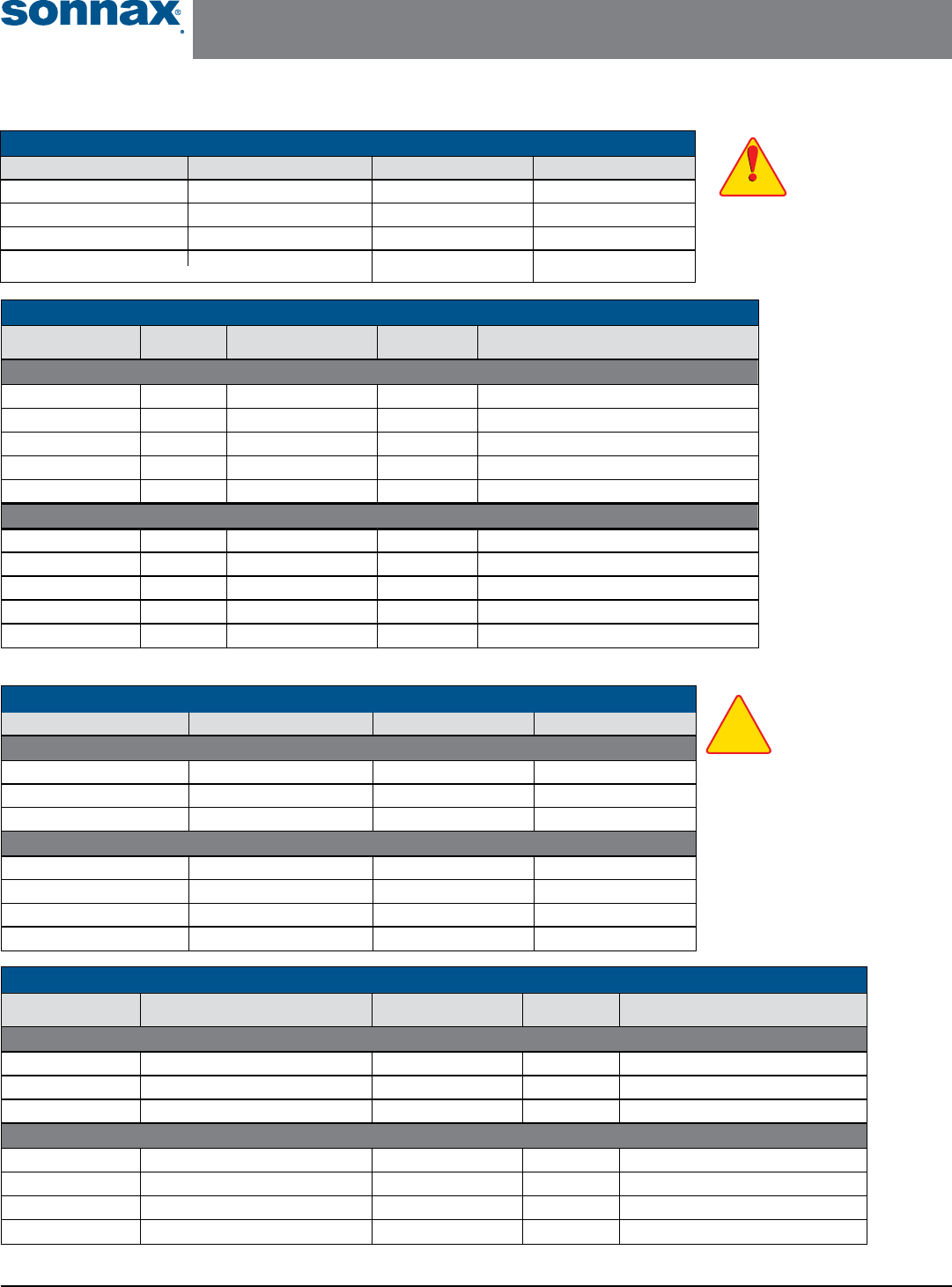
Ford Solenoid O-Ring Sizes
Connector Color Snout Color Inboard O-Ring Size Outboard O-Ring Size
Ford 2007–2009: 6R60
Brown Long Black 10.5 x 2mm 13.5 x 2mm
Black Long Black 10.5 x 2mm 13 x 2mm
Cream White OR-014 OR-016
Ford 2010–Later: 6R60
Tan Brown 10.5 x 2mm 13.5 x 2mm
Tan Black 10.5 x 2mm 13 x 2mm
Tan (2010–2011) White OR-014 OR-016
Tan (2012–Later) Gray OR-014 OR-016
Figure 16
ZF Solenoid Function
Connector Color Location Output Resistance at
68˚F (20˚C) Function
Generation 1: ZF6HP19, ZF6HP26, ZF6HP32
Yellow / Green** EDS 1, 3, 6 0 psi (0 bar) at 0 mA 5.05 ohms 1 – A Clutch; 3 – C Brake; 6 – TCC
Blue / Black /Gray** EDS 2, 4, 5 67 psi (4.6 bar) at 0 mA 5.05 ohms 2 – B Clutch; 4 – D & E Clutch; 5 – EPC
Black MV1 Open/Closed 11.5 ohms Selector Valve
Black MV2 Open/Closed 11.5 ohms Park Lock Valve
Green MV3 Open/Closed 11.5 ohms Park Lock Cylinder
Generation 2: ZF6HP21, ZF6HP28, ZF6HP34
Orange EDS 1, 2 0 psi @ 0mA 5.05 ohms 1 – A Clutch; 2 – TCC
Yellow EDS 4, 5, 6 0 psi @ 0 mA 5.05 ohms 4 – E Clutch; 5 – C Clutch; 6 – D1 & D2 Brake
Blue EDS 3, 7 67 psi @ 0mA 5.05 ohms 3 – B Clutch; 7 – EPC
Black MV2 Open/Closed 11.5 ohms Park Lock Valve
Green MV3 Open/Closed 11.5 ohms Park Lock Cylinder
Figure 15
ZF Solenoid O-Ring Sizes
Connector Color Snout Color Inboard O-Ring Size Outboard O-Ring Size
Yellow / Green** Black 10.5 x 2mm 13.5 x 2mm
Blue / Black / Gray** Yellow 10.5 x 2mm 13 x 2mm
Orange Orange 10.5 x 2mm 14.5 x 2mm
Black Short Black 14.5 x 1.5mm 14.5 x 1.5mm
(Typical MV1 solenoid in Gen 1 & MV2 solenoid on E-Shifts)
Figure 14
** = Found on some
Audi applications
NOTE: Solenoid connector
colors can fade with high
mileage and high temper-
ature. Example: blue can
look like green and yellow can look
like tan.
CAUTIONCAUTION
CAUTIONCAUTION
