Sony Group 1492549 DWAM83 Wireless Audio Module User Manual DWAM83 x
Sony Corporation DWAM83 Wireless Audio Module DWAM83 x
Contents
- 1. 1492549- user manual 2013.7.31
- 2. 1492549-User Manual 2013.12.09
- 3. earphone Use Manual 2013.12.09
1492549- user manual 2013.7.31

GoerTek Confidential Page 1 of 13 7/31/2013
GoerTek
CEP Division
Model or Name: DWAM83
Description: RF Module
Document No.:
Version: 0.5
Issue Date: 2013-07-08
Restricted and Confidential Information Statement:
All information contained in this document is the exclusive property of GoerTek Electronics, Inc.
and its development partners. Any reproduction or disclosure of all or part of this document
without the expressed written consent of GoerTek is strictly prohibited.

GoerTek Confidential Page 2 of 13 7/31/2013
GoerTek
CEP Division
Table of Contents
1Document Scope and Intention .....................................................................................................................5
2Applicable Standards, Documents and References ...................................................................................5
3Glossary ............................................................................................................................................................5
4Product Application Overview ........................................................................................................................6
5Product Outline ................................................................................................................................................6
6Electric Characteristics ...................................................................................................................................7
6.1Block Diagram ........................................................................................................................................................ 7
6.2Key Components List ............................................................................................................................................ 7
7Recommended Operating Conditions ..........................................................................................................8
8DC Characteristics ...........................................................................................................................................8
9Power consumption .........................................................................................................................................8
10RF Characteristics ....................................................................................................................................9
11Interface Definition .................................................................................................................................. 10
12Firmware Version .................................................................................................................................... 12
13Packing and Marks ................................................................................................................................. 12
13.1Module Label ........................................................................................................................................................ 12
GoerTek Confidential Page 3 of 13 7/31/2013
GoerTek
CEP Division
Publication History
No. Version Release issue Prepared by Release date
1 V0.1 Draft version 2013-03-04
2 V0.2 Sensitivity condition modification 2013-05-28
3 V0.3 Packing Proposal Update 2013-06-20
4 V0.4 Add Note1.Note2 for 5.2G 2013-06-26
5 V0.5 Update the typical out power value 2013-07-08
6
7
8
9
10
GoerTek Confidential Page 4 of 13 7/31/2013
GoerTek
CEP Division
Wireless Module
1492549
Type Specification
1. Communication Method: Half Duplex Mode
2. Transmission
a) 2.4G
PARAMETER CONDITION MIN TYP MAX UNITS
RFFrequencyRange 2400‐2483.5MHz
NumberofRF‐channels Carriersin
thespectrum‐ 3‐
TransmissionPower 14dBm
ChannelFrequency
(dynamicorfixed
allocation)
CH1
CH2
CH3
2412
2438
2464
‐ MHz
b) 5.2G
PARAMETER CONDITION MIN TYP MAX UNITS
RFFrequencyRange 5150‐ 5250MHz
NumberofRF‐channels Carriersin
thespectrum‐ 3‐
TransmissionPower 9dBm
ChannelFrequency
(dynamicorfixed
allocation)
CH1
CH2
CH3
5180
5210
(Note1)
5240
‐ MHz
Note 1: For Japan, RF channel 2 will be 5200MHz
c) 5.8G
PARAMETER CONDITION MIN TYP MAX UNITS
RFFrequencyRange 5725‐ 5875MHz
NumberofRF‐channels Carriersin
thespectrum‐ 3‐
TransmissionPower 9dBm
ChannelFrequency
(dynamicorfixed
allocation)
CH1
CH2
CH3
5736
5762
5814
‐ MHz
d) Modulation: QPSK
3. Antenna Peak Gain:2.8dBi
4. Applicant: Sony
5. Product Name: DWAM83 Wireless Module
6. Model Name: 1492549
GoerTek Confidential Page 5 of 13 7/31/2013
GoerTek
CEP Division
1 Document Scope and Intention
The information in this document provides detailed specifications for the Cocoa. All
features and requirements are described hereunder, including mechanical, electrical,
software and reliability.
This document is released to ensure final production units comply with all requirements
and may be updated as necessary.
2 Applicable Standards, Documents and References
STM-1131 Ink and Printed Parts – Quality Standard
STM-1208 Paint and Painted Parts – Quality Standard
STM-1269 Drop Test Methods for Mobile Products
STM-1284 Vapor-Deposited Parts Quality Standards
3 Glossary
Table1 Glossary
FFC Flexible Flat Cable
FPC Flexible Printed Circuit
EMC Electromagnetic Compatibility
FCC Federal Communications Commission
IEC International Electro-technical Commission
RoHS Restriction of Hazardous Substances
UUT Unit Under Test
WEEE Waste Electrical and Electronic Equipment Directive
TBD To Be Determined
GoerTek Confidential Page 6 of 13 7/31/2013
GoerTek
CEP Division
4 Product Application Overview
Cocoa is a digital wireless audio module base on DARR83 wireless audio processor. It is
an uncompressed wireless digital audio transceiver operating in 2.4GHz, 5.2 GHz and 5.8
GHz bands. Cocoa supports point to point connection and bidirectional data transfer. It’s
built in 4M SPI Interface flash, and has a 26pins interface connector for power, digital
audio and control interface and GPIOs. It offers seamless audio connectivity for a wide
range of wireless audio devices.
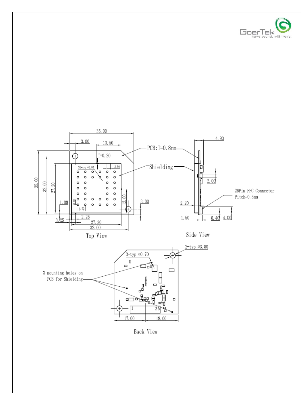
5 Product Outline
Figure1 Cocoa Outline Drawings
Module size: 35 x 35 x 43 mm (±0.15), including 2-Printed Tri-Band antennas
Diameter mounting holes: 3.0mm (±0.05)
GoerTek Confidential Page 7 of 13 7/31/2013
GoerTek
CEP Division
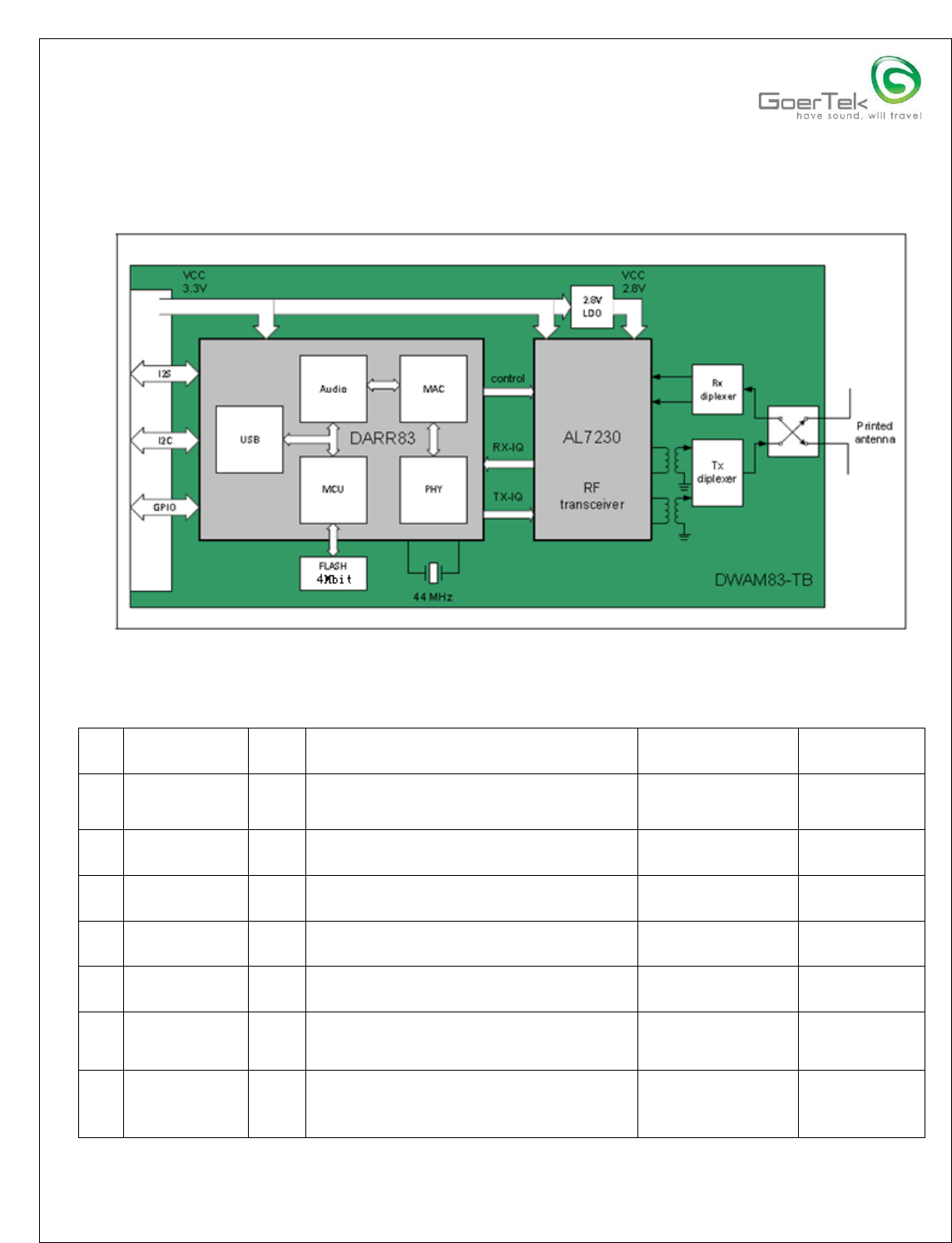
6 Electric Characteristics
6.1 Block Diagram
Figure2 Cocoa Module Block Diagram
6.2 Key Components List
No
. Part Name Qty Description Supplier P/N Supplier
1 BASEBAND
IC 1 STS Audio Baseband Chip DARR83 SMSC
2 RADIO IC 1
802.11a/b/g RF IC,2.4~2.5 GHz and
4.9 ~ 5.9 GHz AL7230S Airoha
3 RF
SWITCH 1 2.4GHz and 6GHz Dual-Band
Wireless Lan Upg2164t5n NEC
4 BALUN 1 Balun 50:100, 2400~2500MHz BL2012-
10B2450T/LF ACX
5 BALUN 1 Balun, 50:50, 5512 ±363MHz LDB215G5105C
-001 MURATA
6 DIPLEXER 2 DIPLEXER,2450.00±50.00MHZ/542
5.00±525.00MHZ LFD212G45DF5
B859 MURATA
7 CRYSTAL 1 44MHz, Frequency
Tolerance:±10ppm, Temperature
Characteristics:±10ppm, CL:6pF
EXS00A-
CS04137 NDK
GoerTek Confidential Page 8 of 13 7/31/2013
GoerTek
CEP Division
No
. Part Name Qty Description Supplier P/N Supplier
8 REGULAT
OR 1 Output voltage: 2.8V, 300mA high
speed, extremely low noise CMOS
LDO regulator
AP2125K-
2.8TRG1 BCD
9 SPI Flash 1
SPI Flash ,4M
bits,2.7~3.6,700,SOP-8 GD25Q40TIGR Gigadevice
Table2 Key Components List
7 Recommended Operating Conditions
SYMBOL PARAMETER MIN TYP MAX UNIT
Vcc Supply Voltage 3.1 3.3 3.5 V
VESD ESD Contact Discharge -2 - +2 KV
Tamb Operating Temperature -10 25 60 ℃
Table3 Recommended Operating Conditions
Connection: 0.5mm*26pin connector
Control Interface: IC
Audio Interface: IS S/PDIF
8 DC Characteristics
SYMBOL PARAMETER MIN TYP MAX UNIT
Vcc Ripple Peak to peak Ripple 0 100 mV
Tr Rise time of Reset 10 ms
Tf Fall time of Reset 10 ms
Treset Reset signal pulse width 1 ms
Table4 DC Characteristics
9 Power consumption
Vcc=3.3V, Ambient temperature 25℃
SYMBOL PARAMETER MIN TYP MAX UNIT
Ii Power down current 23 mA
Im24 Continuous TX current@2.4G 360 mA
Im52 Continuous TX current@5.2G 320 mA
GoerTek Confidential Page 9 of 13 7/31/2013
GoerTek
CEP Division
SYMBOL PARAMETER MIN TYP MAX UNIT
Im58 Continuous TX current@5.8G 320 mA
Table5 Power consumption
10 RF Characteristics
Cocoa transceiver/Receiver operates in 2.4GHz, 5.2 GHz and 5.8 GHz bands.
PARAMETER CONDITION MIN TYP MAX UNITS
RF Frequency Range 2400 - 2483.5 MHz
Number of RF-
channels Carriers in the
spectrum - 3 -
Transmission Power
Depending on
antenna design 13 dBm
Channel Frequency
(dynamic or fixed
allocation)
CH1
CH2
CH3
2412
2438
2464 - MHz
Channel Spacing 26 MHz
RF Bandwidth Null-to-null 22 MHz
RX Sensitivity PER<5% - - -80
Table6 RF Performance of 2.4G Application (Vcc=3.3V, 25℃)
PARAMETER CONDITION MIN TYP MAX UNITS
RF Frequency Range 5150 - 5250 MHz
Number of RF-
channels Carriers in the
spectrum - 3 -
Transmission Power
Depending on
antenna design 9 dBm
Channel Frequency
(dynamic or fixed
allocation)
CH1
CH2
CH3
5180
5210
(Note 1)
5240
- MHz
Channel Spacing 30
(Note 2) MHz
RF Bandwidth Null-to-null 17 MHz
RX Sensitivity PER<5% - - -80
Note 1: For Japan, RF channel 2 will be 5200MHz
Note 2: The Default channel spacing is 30MHz, a 20MHz channel space will be used for Japan
GoerTek Confidential Page 10 of 13 7/31/2013
GoerTek
CEP Division
Table7 RF Performance of 5.2G Application (Vcc=3.3V, 25℃)
PARAMETER CONDITION MIN TYP MAX UNITS
RF Frequency Range 5725 - 5875 MHz
Number of RF-
channels Carriers in the
spectrum - 3 -
Transmission Power
Depending on
antenna design 9 dBm
Channel Frequency
(dynamic or fixed
allocation)
CH1
CH2
CH3
5736
5762
5814 - MHz
Channel Spacing 26 MHz
RF Bandwidth Null-to-null 22 MHz
RX Sensitivity PER<5% -78
Table8 RF Performance of 5.8G Application (Vcc=3.3V, 25℃)
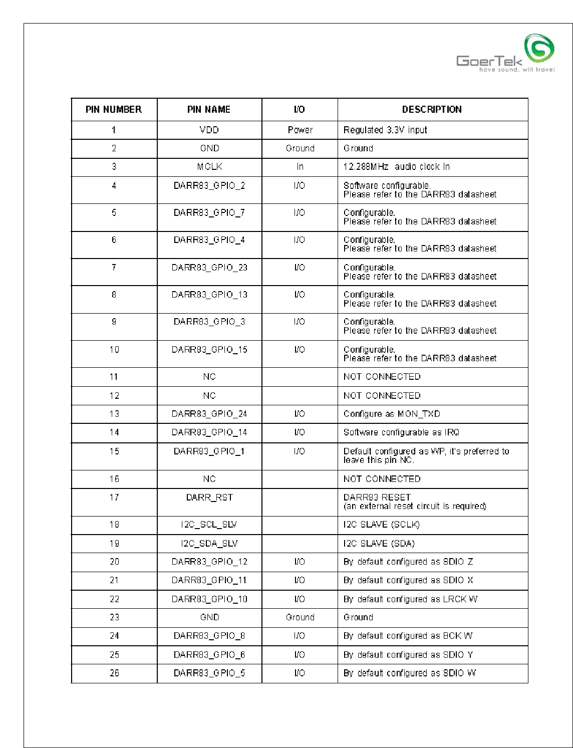
11 Interface Definition
The Module interface is an 26pin FFC .
Spec of FFC connector:
- 0.5mm pitch FPC/FFC connector
- 26 ways, Right Angle Type (double face contact)
- LIF SMT Type
- Tin/Nickel (Lead-Free)
- Halogen Free
GoerTek Confidential Page 11 of 13 7/31/2013
GoerTek
CEP Division
Table9 26pin FFC Definition
GoerTek Confidential Page 12 of 13 7/31/2013
GoerTek
CEP Division
12 Firmware Version
FW is provided by customer.
FW Version: WSLIB_DWAM83_8052_S012.BIN
(Maybe updated base on customer release)
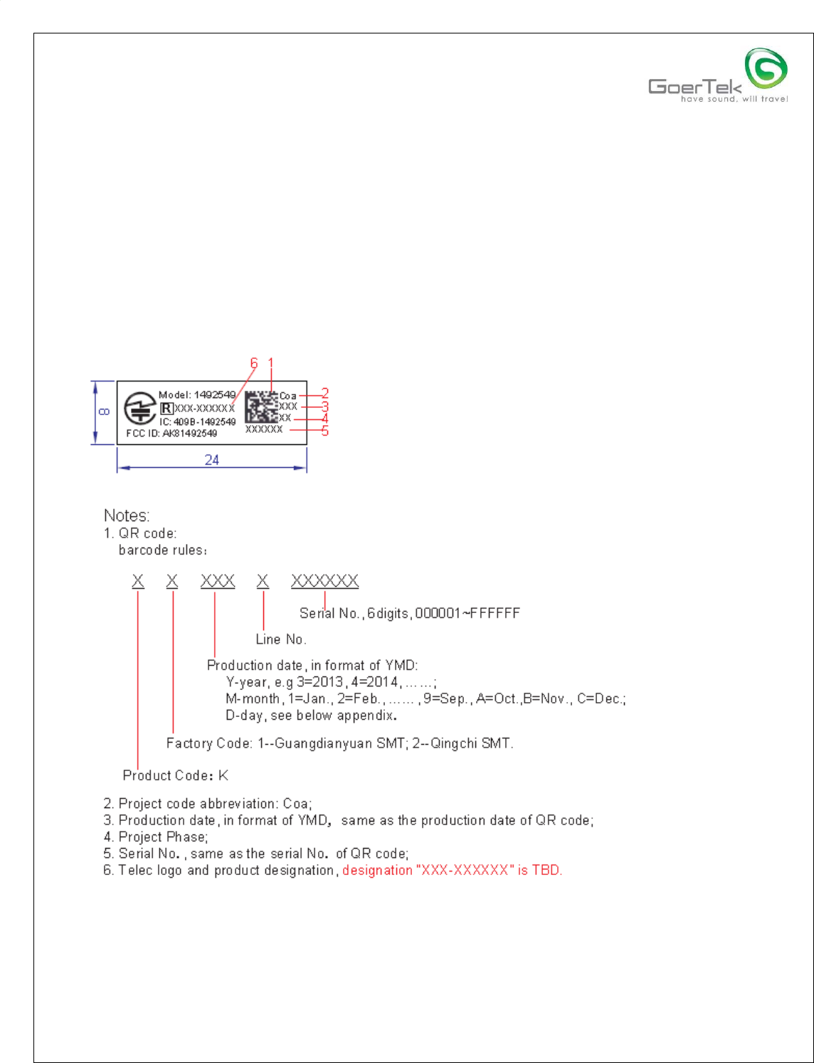
13 Packing and Marks
13.1 Module Label
GoerTek Confidential Page 13 of 13 7/31/2013
GoerTek
CEP Division
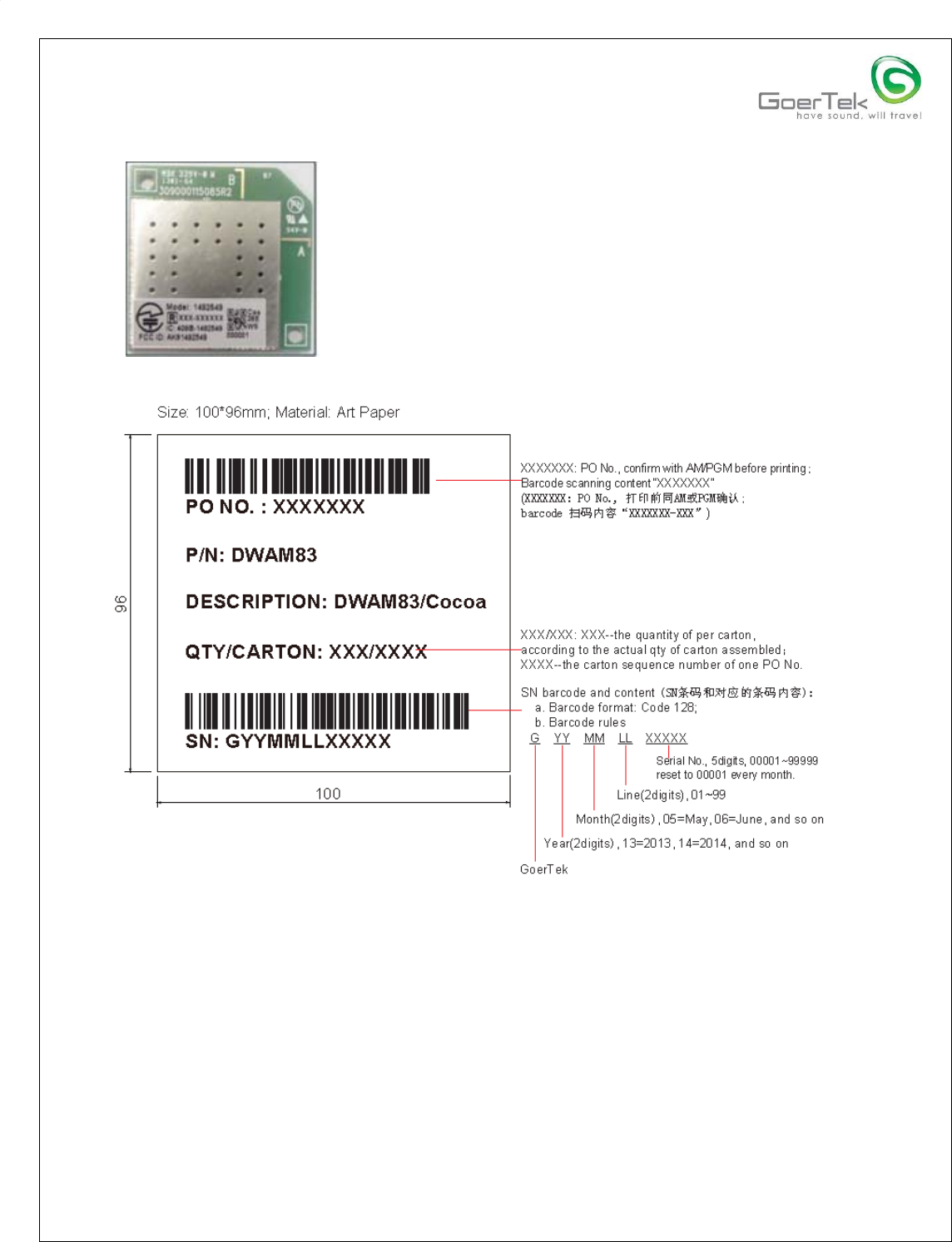
13.2 Carton Label

GoerTek Confidential Page 14 of 13 7/31/2013
GoerTek
CEP Division
FCC Compliance Statement:
This device complies with Part 15 of the FCC Rules. Operation is subject to the following
two conditions:
1. This device may not cause harmful interference, and
2. This device must accept any interference received, including interference that may
cause undesired operation. This device must accept any interference received, including
interference that may cause undesired operation. Product that is a radio transmitter is
labeled with FCC
ID.
FCC Caution:
(1) Any changes or modifications not expressly approved by the grantee of this device
could void the user's authority to operate the equipment.
(2) The modules FCC ID is not visible when installed in the host, or
(3) If the host is marketed so that end users do not have straight forward commonly used
methods for access to remove the module so that the FCC ID of the module is visible; then
an additional permanent label referring to the enclosed module: Contains Transmitter
Module FCC ID: AK81492549 or Contains FCC ID: AK81492549 must be used.
(4) This equipment must be installed and operated in accordance with provided
instructions and the antenna(s) used for this transmitter must be installed to provide a
separation distance of at least 20 cm from all persons and must not be co-located or
operating in conjunction with any other antenna or transmitter. End-users and installers
must be provided with antenna installation instructions and transmitter operating conditions
for satisfying RF exposure compliance.
Note: This equipment has been tested and found to comply with the limits for a Class B
digital device, pursuant to part 15 of the FCC Rules. These limits are designed to provide
reasonable protection against harmful interference in a residential installation. This
equipment generates, uses and can radiate radio frequency energy and, if not installed
and used in accordance with the instructions, may cause harmful interference to radio
communications. However, there is no guarantee that interference will not occur in a
particular installation. If this equipment does cause harmful interference to radio or
television reception, which can be determined by turning the equipment off and on, the
user is encouraged to try to correct the interference by one or more of the following
measures:
—Reorient or relocate the receiving antenna.
—Increase the separation between the equipment and receiver.
—Connect the equipment into an outlet on a circuit different from that to which the receiver
is connected.
—Consult the dealer or an experienced radio/TV technician for help.

GoerTek Confidential Page 15 of 13 7/31/2013
GoerTek
CEP Division
IC Radiation Exposure Statement for Canada
This device complies with Industry Canada licence-exempt RSS standard(s). Operation is
subject to the following two conditions: (1) this device may not cause interference, and (2)
this device must accept any interference, including interference that may cause undesired
operation of the device.
Le présent appareil est conforme aux CNR d'Industrie Canada applicables aux appareils
radio exempts de licence. L'exploitation est autorisée aux deux conditions suivantes : (1)
l'appareil ne doit pas produire de brouillage, et (2) l'utilisateur de l'appareil doit accepter
tout brouillage radioélectrique subi, même si le brouillage est susceptible d'en
compromettre le fonctionnement.
-----------------------------------------------------------------END------------------------------------------------------