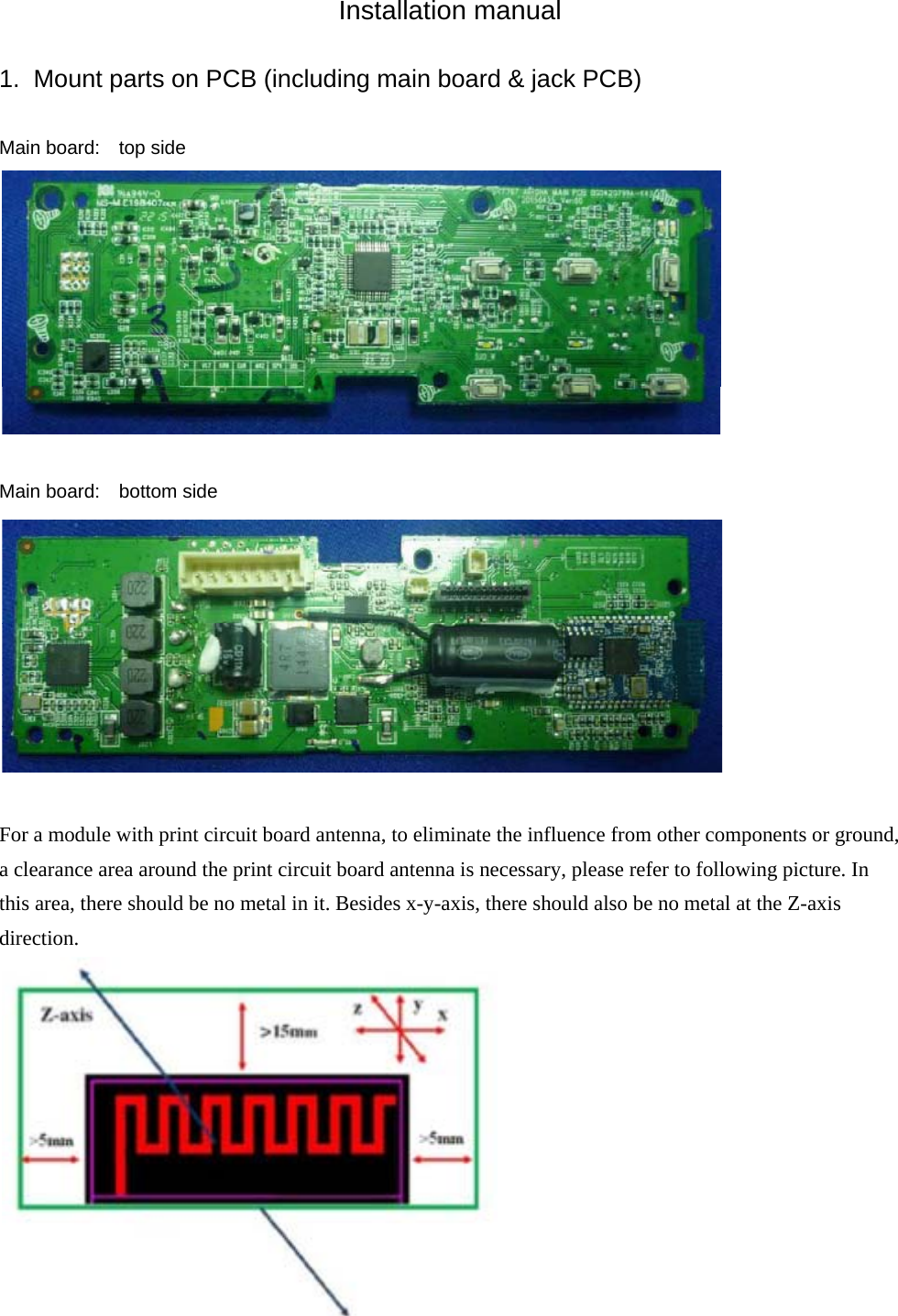
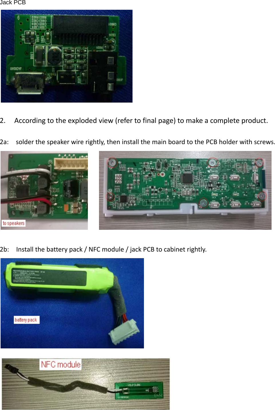
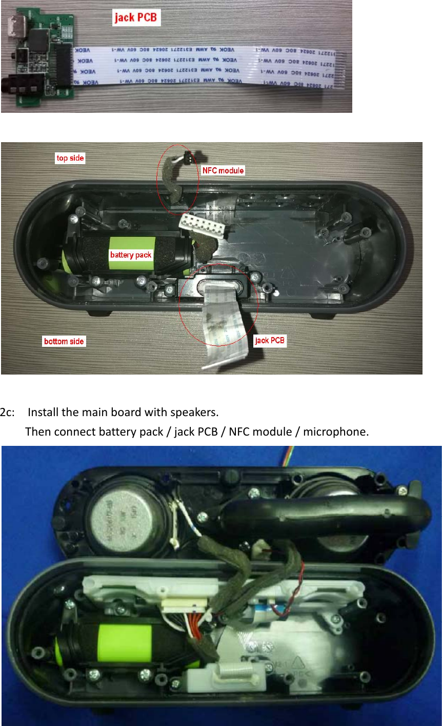
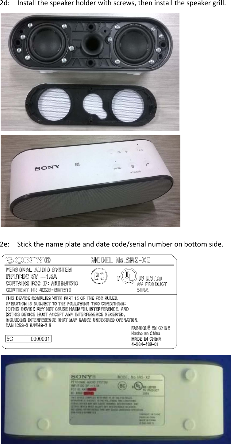
Sony Group BM1510 Bluetooth Module User Manual Installation manual

Sony Corporation Bluetooth Module Installation manual

BM1510_Installation manual Rev1

Installation manual  1.  Mount parts on PCB (including main board & jack PCB)  Main board:    top side  Main board:    bottom side   For a module with print circuit board antenna, to eliminate the influence from other components or ground, a clearance area around the print circuit board antenna is necessary, please refer to following picture. In this area, there should be no metal in it. Besides x-y-axis, there should also be no metal at the Z-axis direction.
Jack PCB2. Accordingtotheexplodedview(refertofinalpage)tomakeacompleteproduct.2a:solderthespeakerwirerightly,theninstallthemainboardtothePCBholderwithscrews. 2b:Installthebatterypack/NFCmodule/jackPCBtocabinetrightly.
2c:Installthemainboardwithspeakers.Thenconnectbatterypack/jackPCB/NFCmodule/microphone.
2d:Installthespeakerholderwithscrews,theninstallthespeakergrill.2e:Stickthenameplateanddatecode/serialnumberonbottomside.
The END host which install this module should bear the label which display “ contains FCC ID:AK8BM1510and contient IC : 409B‐BM1510"


Navigation menu