Sony Group DTPT1000 DTP-T1000 Development Tool User Manual DTP T1000 A
Sony Corporation DTP-T1000 Development Tool DTP T1000 A
Users Manual

Instruction manual
SCE CONFIDENTIAL
DTP-T1000 A
Development Tool
This manual contains safety precautions for the prevention of accidents,
and instructions for the use and handling of this product.
Read this manual carefully and use the product in a safe manner. After
reading the manual, store it in an accessible location for future reference.
2-515-713-11(1)
2
WARNING
WARNING
To avoid electrical shock, do not
open the cabinet. Refer servicing to
qualified personnel only.
Use the supplied AC adaptor only. If
you use other types, it may cause fire,
electrical shocks or a malfunction.
Laser specifications
UMDTM
Wave length: 655-665 nm
Power: max 0.28 mW
Type: Semiconductor, continuous
DVD-ROM
Wave length: 640-660 nm (DVD)
775-805 nm (CD)
Power: max 0.3 mW (DVD)
0.23 mW (CD)
Type: Semiconductor, continuous
For customers in the U.S.A. and Canada
CAUTION
The use of optical instruments with this product will
increase eye hazard. As the laser beams used in the DVD-
ROM and UMD™ drives are harmful to eyes, do not
attempt to disassemble the cabinet.
Refer servicing to qualified personnel only.
This label is located on the DVD-ROM laser protective
housing inside the enclosure.
For customers in the U.S.A.
CAUTION
Use of controls, adjustments or performance of procedures
other than those specified herein may result in hazardous
radiation exposure.
NOTE:
This equipment has been tested and found to comply with
the limits for a Class A digital device, pursuant to Part 15 of
the FCC Rules. These limits are designed to provide
reasonable protection against harmful interference when the
equipment is operated in a commercial enviroment.
This equipment generates, uses, and can radiate radio
frequency energy and, if not installed and used in
accordance with the instructions, may cause harmful
interference to radio communications.
Operation of this equipment in a residential area is likely to
cause harmful interference in which case the user will be
required to correct the interference at his own expense.
You are cautioned that any changes or modifications not
expressly approved in this manual could void your
authority to operate this equipment.
FCC Radio-Frequency Exposure Statement
This equipment complies with FCC radiation exposure
limits set forth for an uncontrolled environment. This
equipment should be installed and operated with minimum
distance 20 cm between the radiator and body (excluding
extremities: hands, wrists and feet).
Owner’s Record
The model and serial numbers are located on the side of the
unit. Record the serial number in the space provided below.
Refer to these numbers whenever you call for technical
assistance at the number shown in "Contact information" on
the back cover of this instruction manual.
Model No. DTP-T1000 A
Serial No.______________
For customers in Canada
This Class A digital apparatus complies with Canadian
ICES-003.
The term “IC” before the equipment certification number
only signifies that the Industry Canada technical
specifications were met.
Pour les utilisateurs au Canada
Cet appareil numérique de la classe A est conforme à la
norme NMB-003 du Canada.
Le terme “IC” avant le numéro d’homologation ne signifie
seulement que les normes d’Industrie Canada ont été
respectées.
For customers in Europe
CAUTION
The use of optical instruments with this product will
increase eye hazard. As the laser beams used in the DVD-
ROM and UMD™ drives are harmful to eyes, do not
attempt to disassemble the cabinet.
Refer servicing to qualified personnel only.
This label is located on the DVD-ROM laser protective
housing inside the enclosure.
WARNING
This part of the manual would be modified
for:
"This equipment complies with FCC radiation
exposure limits set forth for an uncontrolled
environment. This
equipment should be installed and operated with
minimum
distance 20 cm between the radiator and body This
transmitter must no be co-located or operating in
conjunction with any antenna or transmitter"
3
WARNING
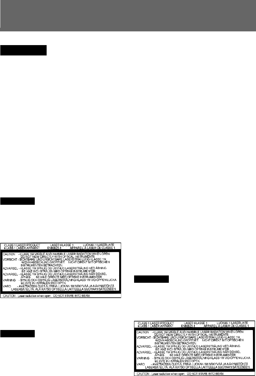
This appliance is classified as a CLASS 1 LASER product.
The CLASS 1 LASER product marking is located on the rear
of the product.
This equipment complies with EN55022 CLASS B and
EN55024 for use in the following areas: residential,
business, and light-industrial.
This equipment has been tested and found to comply with
the limits set out in the EMC Directive using a connection
cable shorter than 3 metres.
Audio and picture distortion may occur if this equipment is
positioned in close proximity to any equipment emitting
electromagnetic radiation.
If this unit is affected by static electricity or burst-noise, it
may not work correctly.
Dit apparaat bevat een vast ingebouwde batterij die niet
vervangen hoeft te worden tijdens de levensduur van het
apparaat. Raadpleeg uw leverancier indien de batterij toch
vervangen moet worden. De batterij mag alleen vervangen
worden door vakbekwaam servicepersoneel.
Gooi de batterij niet weg maar lever deze in als klein
chemisch afval (KCA).
Lever het apparaat aan het einde van de levensduur in voor
recycling, de batterij zal dan op correcte wijze verwerkt
worden.
WARNING
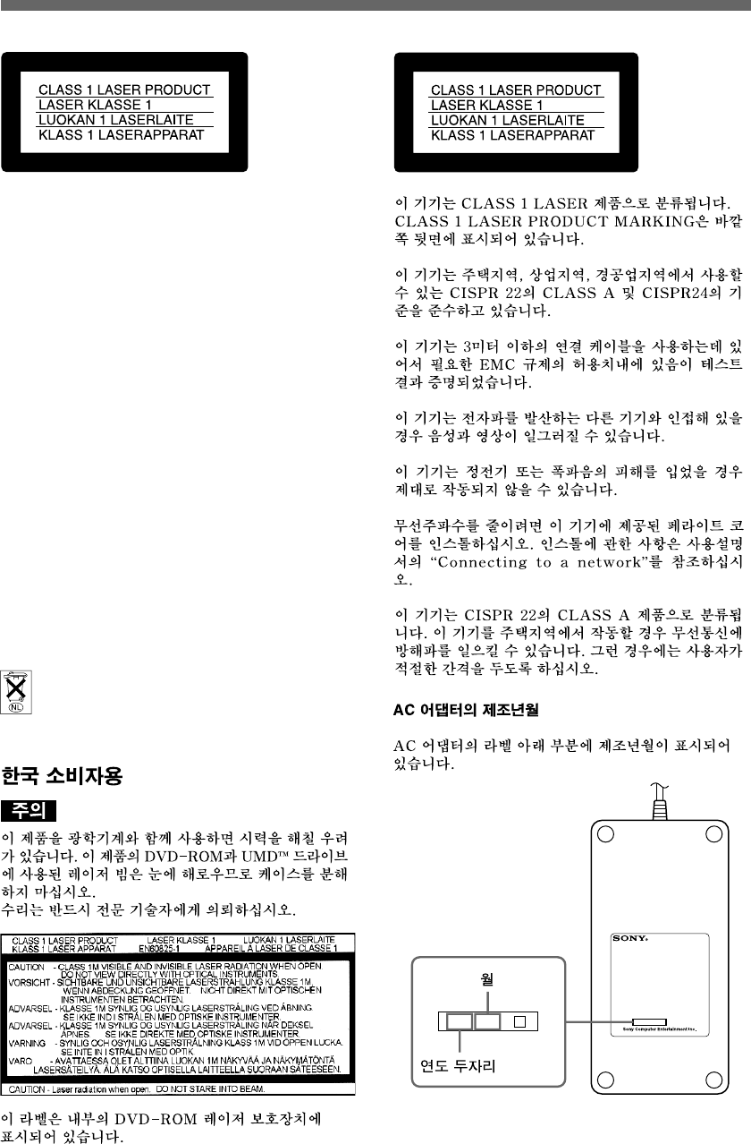
For customers in Korea
0 4 1 2

4
For your protection, please read these
safety instructions completely before
operating the appliance, and keep this
manual for future reference.
Carefully observe all warnings,
precautions and instructions on the
appliance, or those described in the
instruction manual and adhere to them.
USE
Power sources
This unit should be operated only from the type of
power source indicated on the marking label. If you
are not sure of the type of electrical power supplied
to your home, consult your dealer or local power
company. For those units designed to operate from
battery power, or other sources, refer to the
operating instructions.
Overloading
Do not overload wall outlets, extension cords or
convenience receptacles beyond their capacity,
since this can result in fire or electric shock.
Liquid and foreign objects
Never push objects of any kind into the unit through
openings as they may touch dangerous voltage
points or short out parts that could result in a fire or
electric shock. Never spill liquid of any kind on the
unit.
Attachments
Do not use attachments not recommended by the
manufacturer, as they may cause hazards.
Cleaning
Unplug the unit from the wall outlet before cleaning
or polishing it. Do not use liquid cleaners or aerosol
cleaners. Use a cloth lightly dampened with water
for cleaning the unit exterior.
INSTALLATION
Water and moisture
Do not use the powerline operated unit near water –
for example, near a bathtub, washbowl, kitchen
sink, or laundry tub, in a wet basement or near a
swimming pool, etc.
Power cord protection
Route the power cord so that it is not likely to be
walked on or pinched by items placed upon or
against it, paying particular attention to the plugs,
receptacles, and the point where the cord exits from
the unit.
Ventilation
The slots and openings in the cabinet are provided
for necessary ventilation. To ensure reliable
operation of the unit, and to protect it from
overheating, these slots and openings must never be
blocked or covered.
–Never cover the slots and openings with a
cloth or other materials.
– Never block the slots and openings by placing
the unit on a bed, sofa, rug or other similar
surface.
Accessories
Do not place the unit on an unstable cart, stand,
bracket or table. The unit may fall, causing serious
injury to a child or an adult, and serious damage to
the unit.
Use only a cart, stand, tripod, bracket, or table
recommended by the manufacturer.
An appliance and cart combination should be
moved with care. Quick stops, excessive force, and
uneven surfaces may cause the appliance and cart
combination to overturn.
– Never place the unit in a confined space, such
as a bookcase, or built-in cabinet, unless
proper ventilation is provided.
–Do not place the unit near or over a radiator or
heat register, or where it is exposed to direct
sunlight.
Important safeguards
Important safeguards

5
SERVICE
Damage requiring service
Unplug the unit from the wall outlet and refer
servicing to qualified service personnel under the
following conditions:
– When the power cord or plug is damaged or
frayed.
– If liquid has been spilled or objects have fallen
onto the unit.
– If the unit has been exposed to rain or water.
–If the unit has been subject to strong physical
shock by being dropped, or the cabinet has
been damaged.
–If the unit does not operate normally when
following the instruction manual. Adjust only
those controls that are specified in the
instruction manual. Improper adjustment of
other controls may result in damage and will
often require extensive work by a qualified
technician to restore the unit to normal
operation.
– When the unit exhibits a distinct change in
performance – this indicates a need for service.
Servicing
Do not attempt to service the unit yourself as
opening or removing the exterior casing may expose
you to dangerous voltage or other hazards.
Refer all servicing to an authorized service center.
Refer to the contact information on the back cover
to receive instructions on obtaining repair/
replacement services.
Replacement parts
When replacement parts are required, be sure the
service technician has used replacement parts
specified by the manufacturer that have the same
characteristics as the original parts.
Unauthorized substitutions may result in fire,
electric shock, or other hazards.
Safety check
Upon completion of any service or repairs to the
unit, ask the service technician to perform routine
safety checks (as specified by the manufacturer) to
determine that the unit is in safe operating
condition.
Important safeguards
Important safeguards

6Table of contents
Connecting to a network ...................................................... 15
Unit or accessories necessary for connecting ....................... 15
Connection diagrams ............................................................ 15
Connecting peripherals ......................................................... 16
Setting up ............................................................................... 17
Information necessary for setup ........................................... 17
Preparing for setup ............................................................... 17
Turning on the unit ............................................................... 17
Confirming information settings .......................................... 18
Starting the Administration Tool .......................................... 18
Setting up .............................................................................. 19
Showing status ...................................................................... 24
Usage notice ......................................................................... 25
Chapter 3
Appendices
About this product .................................................................. 9
Part names and usage .......................................................... 10
System configuration example ............................................ 14
Chapter 2
Preparing to use
the unit
Table of contents
WARNING ................................................................................. 2
Important safeguards ............................................................. 4
Precautions.............................................................................. 7
Troubleshooting .................................................................... 26
Specifications ........................................................................ 28
R&TTE Directive "Informal DoC" statement ....................... 29
Limitations of liability ........................................................... 30
Chapter 1
Overview

Overview
7
Safety
This product has been designed with the highest concern for safety. However, any electrical device, if
used improperly, has the potential for causing fire, electrical shock or personal injury. To help ensure
accident-free operation, follow these guidelines.
•Observe all warnings, precautions and instructions.
• Stop use and unplug the AC power cord from the electrical outlet if the unit functions in an abnormal
manner, or produces unusual sounds or smells.
• Call the number listed on the back cover for technical assistance if the device does not operate
properly.
• Do not remove the unit’s exterior or disassemble the unit. The laser beam emitted from the lens of this
unit may be harmful to the eyes.
• Do not use the unit near water.
• Stop using the unit immediately if you experience any of the following symptoms. If the condition
persists, consult a doctor.
– Lightheadedness, nausea or a sensation similar to motion sickness
– Tired, uncomfortable or aching hands or arms
– Tired, dry or aching eyes
•Avoid looking at the screen for prolonged periods of time.
• Listening to sound continuously for a long time with a high volume may adversely affect the ears. Be
careful, especially when using headphones. Adjust the volume so that surrounding sounds can be
heard.
• Do not close the disc tray or disc cover in a way that could pinch your hand or fingers, as personal
injury or damage to the unit could result.
Use and handling
•Do not use the unit or accessories outdoors.
• Do not throw or drop the unit or accessories, or expose the devices to strong physical shock.
• Do not place the unit or accessories on surfaces that are unstable, tilted or subject to vibration.
• Do not expose the unit or accessories to high temperatures, high humidity or direct sunlight.
• Do not block the vents.
• Do not wrap the unit in cloth or similar materials.
• Do not allow dust to build up on the unit.
• Do not place the unit in locations of poor ventilation, such as small, enclosed areas, directly against a
wall or on a thick carpet or bedding.
• Do not expose the unit to dust, smoke or steam.
• Do not allow liquid or small particles to get into the unit.
• Do not put heavy objects on the unit.
• Do not place anything in front of the disc tray.
• Do not use damaged, reshaped or repaired discs.
• Do not touch or insert foreign objects into the connectors of the unit or accessories.
• Do not insert cords and cables at an angle. Doing so may damage the connector pins or create the risk
of fire.
• Do not set the unit other than in the vertical position.
• If a spring or screw is provided to secure a cable connector, use the provided spring or screw to secure
it. Take care to prevent making faulty connections.
Precautions
Precautions

Overview
8
AC adaptor and AC power cord use
•To help ensure safe operation, during initial setup and regularly thereafter, inspect the AC adaptor and
AC power cord. If damaged, stop use immediately and call the number on the back cover for
assistance.
• Do not use AC adaptors or AC power cords other than those provided or designated in the instruction
manual. If the provided or designated AC adaptor or power cord is not used, electrical shock may
result or the unit may not operate.
• Do not modify or damage the AC power cord.
• Do not place the AC adaptor between the unit and a wall or shelf.
• Do not place heavy objects on the AC power cord.
• Check that there is no dust or lint on the power plug before inserting into an electrical outlet. If the
plug becomes dirty, wipe it off with a dry cloth before connecting.
• When inserting the AC power cord into an electrical outlet, insert the plug straight into the electrical
outlet and not at an angle.
• Unplug the AC power cord from the electrical outlet before cleaning or moving the unit, or when you
do not intend to use the unit for an extended period of time. When disconnecting, grasp the power cord
by the plug and pull straight out of the electrical socket. Never pull by the cord and do not pull out at
an angle.
• Do not touch the plug of the AC power cord with wet hands.
• Do not touch the power plug during an electrical storm.
• Do not touch the unit or AC adaptor for extended periods of time while the unit is turned on, as
extended contact may cause low-temperature burns.
Cleaning
• For safety reasons, before cleaning the unit or connected accessories, 1) turn off the unit, 2) disconnect
the power plug for the unit from the electrical outlet.
Moisture condensation
• If the unit or disc is brought directly from a cold location to a warm one, moisture may condense on
the lens inside the unit or on the disc. Should this occur, the unit may not operate properly. In this case,
remove the disc and turn off and unplug the unit. Do not put the disc back in until the moisture
evaporates (this may take several hours). If the unit still does not operate properly, obtain technical
assistance using the contact information on the back cover.
Precautions
Precautions

Overview
9
Chapter1
Overview
About this product
This unit is equipped with features for the development of PSPTM software.
The unit can download software or data from a local area network, allowing for the efficient debugging,
running and checking of programs.
• PSPTM features are provided for efficient software development.
• A built-in communication processor allows software, data etc. to be easily sent and received through
the development PCs and networks.
• A direct network connection can be established for easy installation and additions. Also, the load on
development PCs can be reduced.
• Two types of drives are built in: a UMDTM drive, and a DVD-ROM drive, which is used during
development. A switch is used to select the desired drive.
For proper operation, separate development software and a development PC are required.
For details, contact technical support using the contact information on the back cover.
About this product
Overview
10
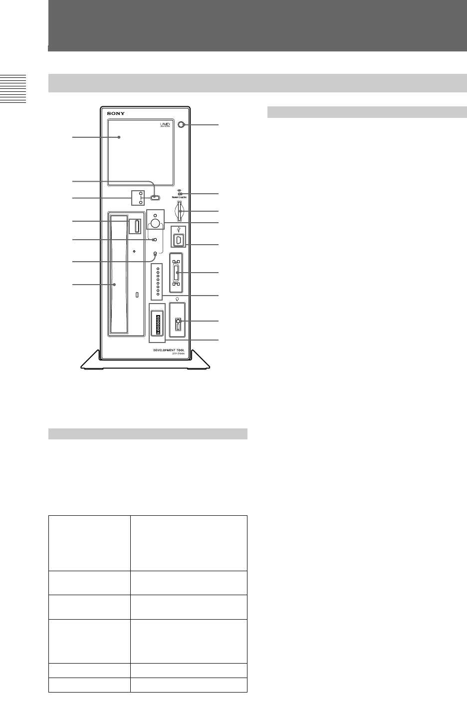
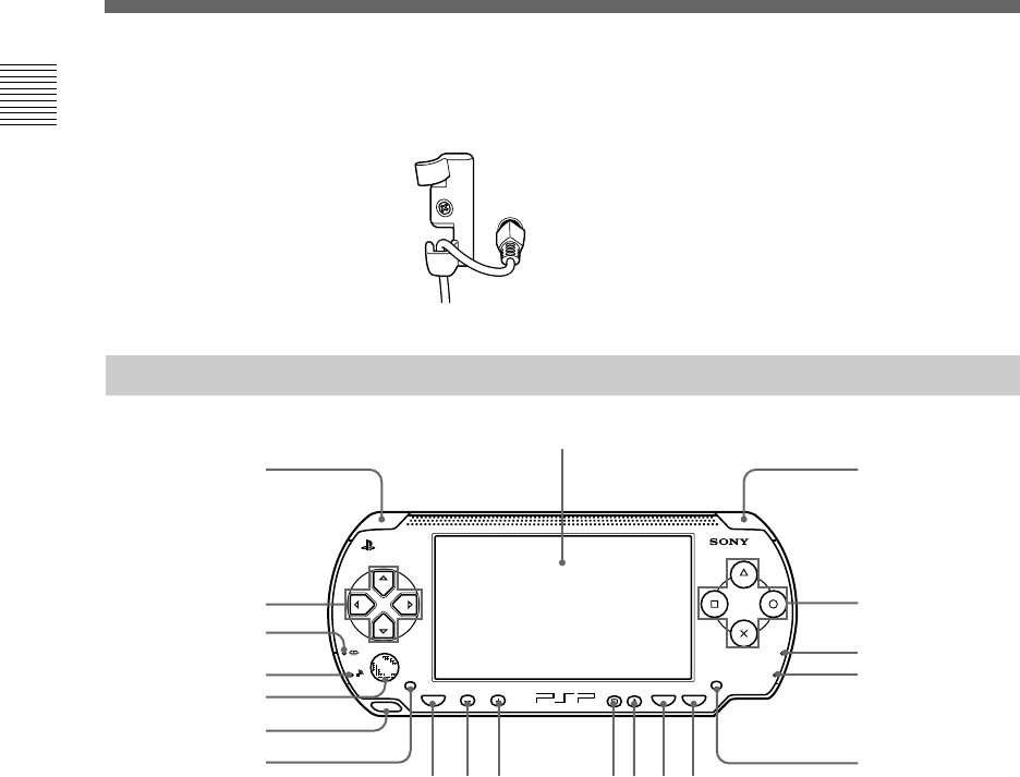
Unit front
Part names and usage
DRIVE SELECT
POWER
SYSTEM INIT
NETWORK INIT
UMD
CONTROLLER
GPO
GPI
ON OFF
DVD
0
7
6
5
4
3
2
1
0
1
2
3
4
5
6
7
1
Z
Z
1
On/standby
button, power
indicator
This button turns the unit on and off.
To turn on the unit
Press the on/standby button while it is in standby
mode. The power indicator flashes green as the
power turns on. The indicator then turns solid
green when the system is ready. The system
status can be determined by the color and status
of the power indicator.
Turning the unit off (standby mode)
•Press the on/standby button and hold it down
for three seconds. The power indicator will
flash and then turn orange, at which point the
power will be turned off (and the system will
enter standby mode).
• Remove the power plug from the electrical
outlet after the power indicator turns a solid
orange. If the plug is removed before the
indicator turns orange, failure of the unit may
result.
2 Disc cover
The open button (3) is used to open the cover
so that UMDTM can be inserted. When closing,
press the middle of the upper edge of the disc
cover.
3 Open button
This button is used to open the disc cover (2).
4 Memory Stick DuoTM access
indicator
Turns orange while the unit is accessing a
Memory Stick DuoTM or Memory Stick PRO
DuoTM that has been inserted into the unit.
5 Memory Stick DuoTM slot
This slot accepts Memory Stick DuoTM or
Memory Stick PRO DuoTM media.
6 USB connector
For connecting USB connectors (mini-B type).
When the included controller is connected to the
USB connector, the controller’s USB connector
becomes functional.
7
Drive select button
Switches between the UMDTM drive and the
DVD-ROM drive.
The selected drive is identified by the UMDTM/
DVD-ROM drive indicators (8). The drive
select button (7) can be used only when the
power indicator of the controller is not lit.
8 UMDTM/DVD-ROM drive indicator
The indicator for the drive, UMDTM or DVD-
ROM, turns orange to indicate which drive is
selected.
9 Open/close button
This button is used to open/close the DVD-ROM
drive.
2
7
8
9
q;
qa
qs
3
4
5
1
6
qd
qf
qg
qh
Flashing green
Solid green
Flashing red
Solid red
Flashing orange
Solid orange
The system is preparing to
start up (flashes until the
system becomes available
after the on/standby button
is pressed)
The system is starting up
(the unit can now be used)
During system initialization
(auto-recovery)
System initialization or
update failure (indicates the
need to initialize the
system)
During network initialization
Standby mode
Part names and usage
Overview
11
q; System initialise button
While holding down this button, pressing the
on/standby button (1) returns the
communication processor software to the factory
default initial state.
qa Network initialise button
While holding down this button, pressing the
on/standby button (1) restores the factory
default values for the IP address settings.
qs DVD-ROM drive
This drive accepts DVD-ROM discs. Use the
open/close button (9) to insert and remove
discs.
qd Controller port
Connects with the commander interface
connector of the attached controller.
qf GPO indicator
These are eight indicators that are user-definable
by PSPTM software developers.
qg Headset connector
A dedicated PSPTM headset remote controller or a
commercially sold headset (with a stereo mini-
plug) can be connected here.
qh GPI switch
These are eight dip switches that are user-
definable by PSPTM software developers.
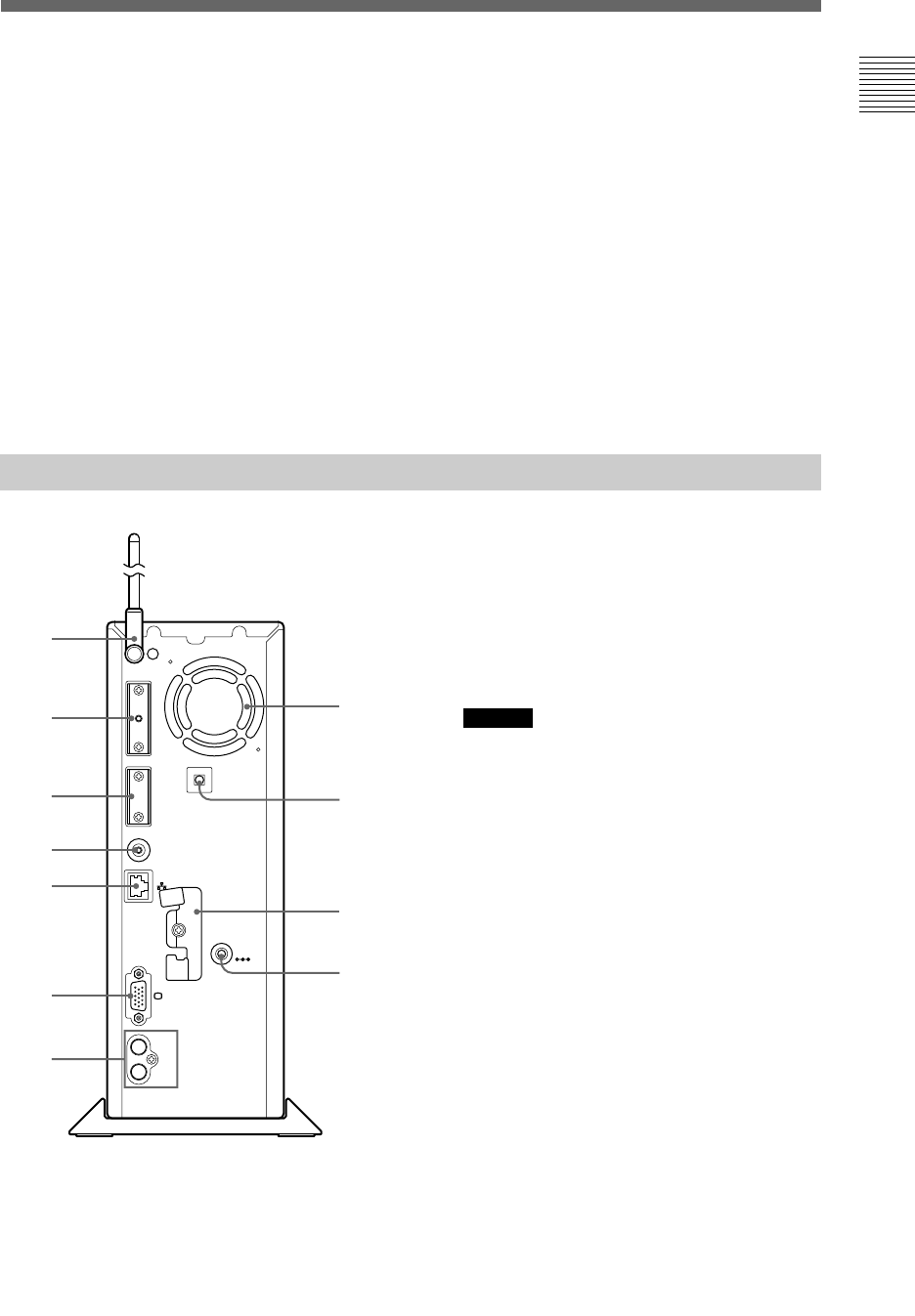
Unit rear
EXT
RF (EXT)
FOOT SW
DC IN
19.5V
L
AUDI O OUT
R
1 Aerial
For wireless LAN use.
2 Extension connector
For use by service personnel only.
3 Serial port
For use by service personnel only.
Caution
Usage of this port may cause irreparable damage to the
system.
4 Foot switch connector
Connects to the supplied foot switch.
5 Network connector
Connector for a network cable. Allows
connection to a local area network.
6 VGA connector
Connects to a device with a VGA IN connector.
7 AUDIO OUT connector
Connects to a device with an AUDIO IN
connector.
8 Vent fan
Vent for internal fan used to cool unit. Be sure
not to obstruct this vent, as doing so may cause a
fire. Also, to prevent any hindrance to air flow,
position the unit an adequate distance from walls.
1
2
3
4
5
6
8
9
q;
7
qa
Part names and usage
Part names and usage
Overview
12
Controller front
1 LCD screen
2 L button
3 R button
4 Up, down, left, right buttons
5 △△
△△
△, ○○
○○
○, ×, □□
□□
□ buttons
6 Power indicator
7 Hold indicator
8 Memory Stick DuoTM access
indicator
9 WLAN access indicator
q; Analog stick
POWER
HOLD
SELECT
HOME VOL START
qa Strap holder
qs Left speaker
qd Right speaker
qf Home button
qg Volume - button
qh Volume + button
qj Display button
qk Sound button
ql Select button
w; Start button
2
4
8
9
q;
qa
qs
1
qf qg qh qjqkqlw;
3
5
6
7
qd
Part names and usage
9 RF (extension) connector
Connects to an access point using a coaxial cable.
q; Clamp
For securing the aerial and
AC adaptor to the unit.
qa DC IN 19.5V connector
For attaching the included AC adaptor.
Part names and usage
Overview
13
Controller front
1 IR port
2 USB connector
LR
2
1
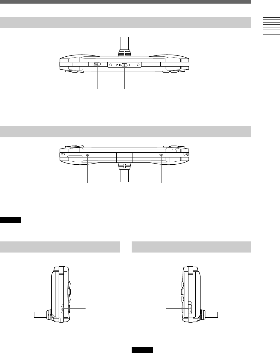
Controller bottom
Controller left Controller right
1 WLAN switch 1 Power/hold switch
Caution
For this product, the debugger (dstdb) reset command cannot
be used when the power/hold switch of the controller is in the
hold position. Make sure that the controller's power/hold
switch is not in the hold position when operating the
debugger.
11
Part names and usage
Part names and usage
2
1
1 Left speaker
2 Right speaker
Caution
Do not cover or insert foreign objects into the speakers as doing so may result in damage to the controller.
Overview
14
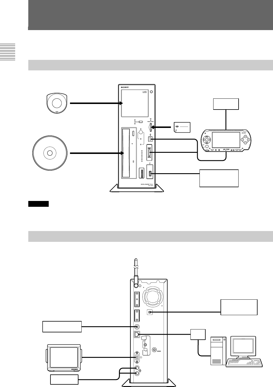
Unit front
DRIVE SELECT
POWER
SYSTEM INIT
NETWORK INIT
UMD
CONTROLLER
GPO
GPI
ON OFF
DVD
0
7
6
5
4
3
2
1
0
1
2
3
4
5
6
7
1
Z
Z
POWER
HOLD
SELECT
HOME VOL START
To UMDTM drive
To DVD-ROM drive
To Memory Stick DuoTM
slot
To headset
connector
Headset
remote controller
USB device
To USB
connector
To controller port
Unit rear
EXT
FOOT SW
L
AUDI O OUT
R
RF (EXT)
DC IN
19.5V
To foot switch
connector
To VGA connector
Foot switch
Monitor
Speaker
To network connector
Wireless LAN
access point
To RF (extension)
connector
To USB connector
Development PC
Hub
System configuration example
The following accessories may be connected to the unit.
System configuration example
To AUDIO OUT
connector
Caution
When you connect or disconnect the controller, turn off power to the unit (keep it in standby mode). If the power is left on, it may
result in damage to the unit or the controller.
Before connecting a cable, rotate the
aerial in a clockwise direction, and raise it
upright. If the cable is connected first, it
may not be possible to rotate the aerial.
Preparing to use the unit
15
Chapter2
Preparing to use
the unit
Connecting to a network
Unit or accessories
necessary for connecting
The following devices and accessories are
necessary in order to use this unit as a
development machine:
•Development Tool
•Network cable
•Hub
•Development PC
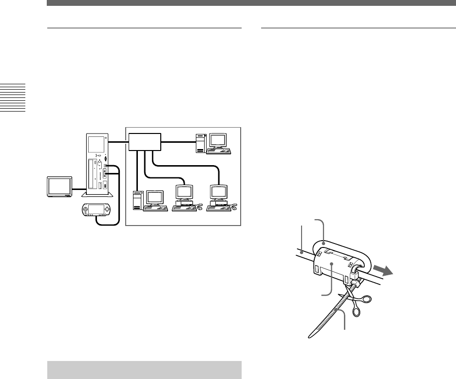
Connection diagrams
Before connecting a cable, rotate the aerial in a
clockwise direction, and raise it upright. If the
cable is connected first, it may not be possible to
rotate the aerial.
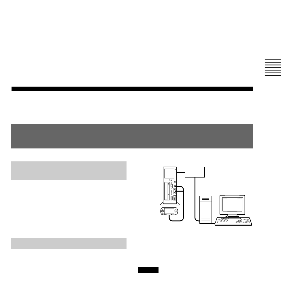
Connecting to a network without a
DHCP server
You can build a local network with this unit and
a development PC in the following manner.
At this time, the following static IP addresses are
automatically set for the unit:
•IP address : 192.168.0.10
•Subnet mask : 255.255.255.0
Caution
• The IP address and subnet mask settings are default factory
settings. When the network settings for the unit are
modified, these settings are also modified accordingly.
• To modify the IP address, start up both the unit and the
development PC, and configure their respective settings to
support the network to which they are to be connected.
After configuration, use a network cable to connect the unit
and the development PC to a hub within the network in use.
Refer to “Setting up” on page 17 for infomation on how to
set up the unit.
Hub
Controller
The unit
Development PC
Connecting to a network
Preparing to use the unit
16
Connecting to a network with a DHCP
server
Connect the unit and a development PC running
the DHCP client software to a hub on the
network.
In this case, the IP address and subnet mask
settings will be obtained automatically when the
unit is turned on. Depending on the settings of
the DHCP server, other network settings, such as
the DNS server and default gateway, may also be
obtained. For details on which settings can be
automatically obtained, contact your network
administrator.
Connecting peripherals
1Connect the unit to a hub using a
network cable.
2Connect the hub to the development
PC using a network cable.
Hub
Controller
The unit
Development PCs
Monitor
Network
Connecting to a network
Connecting to a network
When using the unit in Europe,
Oceania and Korea
Install the supplied RFI filter on the network
cable (unshielded twisted pair cable). Install the
RFI filter near the main unit.
When installing the RFI filter on the cable, wind
the cable once around the RFI filter, as shown
below.
There is a band supplied for use with the RFI
filter. Use the band to attach the RFI filter to the
cable. Fit the band to the cable, as shown below.
cable
RFI filter
Install near the unit
Cut after fitting
Band

Preparing to use the unit
17
Connecting to a network with a DHCP
server
1Turn on the development PC.
2Configure the development PC.
Run the DHCP client software and configure
it so that the development PC can obtain the
IP address and other settings from the DHCP
server. Refer to the instructions supplied with
the development PC for details on how to
configure the PC to run the software and
obtain an IP address. Next, configure the
development PC to run a Web browser.
3Configure the DHCP server.
When the IP address is automatically
obtained by the DHCP server, the specific IP
address allotted to a device is generally
different each time the device is connected to
the network. However, the use of the unit can
be made more convenient by setting the same
IP address to be allotted each time the device
is connected. Contact your network
administrator for details on how to set a static
IP address.
Turning on the unit
After configuring the TCP/IP settings of the
development PC, turn on the unit.
1Connect the AC power cord to the AC
adaptor, then connect the AC adaptor
to the unit.
2Insert the AC power cord into an
electrical outlet.
The power indicator turns orange, and the
unit enters standby mode.
3Press the on/standby button.
This turns on the unit and starts system
initialization. During initialization, the power
indicator flashes green. This indicator stops
flashing when initialization is complete.
Caution
• When turning on the unit, be sure to use the supplied AC
adaptor.
• Do not operate the unit during initialization.
Setting up
Information necessary for
setup
The following information is required for the
setup of the unit.
•DHCP server availability
•IP address
•Subnet mask
•IP address of the default gateway
Check with your network administrator about the
structure of the network to which this unit will be
connected.
Preparing for setup
Before setting up the unit, you need to configure
your development PC.
Connecting to a network without a
DHCP server
1Turn on the development PC.
2Configure the TCP/IP settings of the
development PC.
Configure the TCP/IP settings as follows:
• IP address of the development PC
192.168.0.2
• Subnet mask of the development PC
255.255.255.0
Activate the Web browser on the
development PC, and configure it so that it
does not use a proxy.
Refer to the development PC’s instruction
manual for details.
Setting up
Preparing to use the unit
18
Confirming information
settings
Confirm that the information below is displayed
on the controller LCD:
•IP Address
•Subnet mask
•Broadcast address
•IP address of the default gateway
•Mac address
•Host name
Caution
When you connect or disconnect the controller, turn off
power to the unit (keep it in standby mode). If the power is
left on, it may result in damage to the unit or the controller.
Starting the Administration
Tool
Start up the Administration Tool on the
development PC. The following section assumes
use of the IP address 192.168.0.10 for the unit.
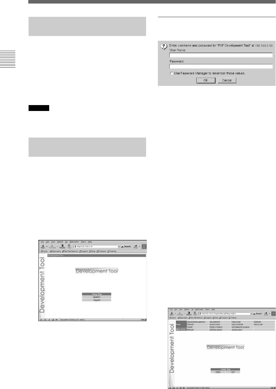
1Start the Web browser on the
development PC.
2Type “http://192.168.0.10/” and press
the “Enter” key.
The language selection screen is displayed.
3Select the display language for the
administration tool.
The login screen is displayed.
Select the language (for example English) here.
Login
Log in with a user name and password.
Enter the user name and password.
1Enter the user name and password as
follows.
To log in as the administrator, enter the
“Administrator” user name and password as
follows:
• user name: Administrator
• password: Administrator
*These are the factory default settings.
When logged in as the administrator, all of
the functions shown in the Administration
Tools menu are active.
To log in as a user, enter the user name and
password as follows:
• user name: User
• password: User
*These are the factory default settings.
When logged in as a user, only the “Status
Display” functions shown in the
Administration Tools menu are active. The
“Settings” functions cannot be used.
2Click [OK].
Upon successfully logging in, the main
screen of the Administration Tool is
displayed.
Setting up
Setting up
Preparing to use the unit
19
Setting up
Setup
These options allow the user to modify settings,
update the software and shut down the unit.
Show status
The following unit settings can be displayed.
Online help
You can view the Help for the Administration
Tool.
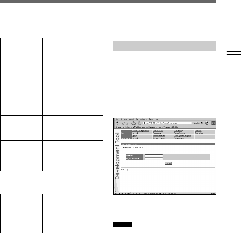
Setting up
Click on the items to the right of “Setup” to
configure each setup.
Administrator password
Upon clicking “Administrator password”, the
following screen is displayed. This screen is
utilized to change the password used for
administrator authentication.
Enter the desired password in the “Password” and
“Retype Password” fields. Click “Setting” to
complete the configuration.
Caution
• For security purposes, be sure to change the default
password.
• The password must be a combination of both letters and
numeric characters. Passwords consisting of all lowercase,
all uppercase or all numeric characters are not allowed.
• A password may be seven or eight characters long.
Passwords fewer than seven characters long are not allowed.
Also, if nine or more characters are entered, only the first
eight characters are set as the password.
• If an error is made in entering the password, or the values
entered into the “Password” and “Retype password” fields
do not match, an error message is displayed. If this occurs,
enter the password again.
Setting up
Network
Softwave version
Access control
Verify the network settings
Verify the version numbers
of installed software
packages
Display dsnet access
control settings
Administrator
password
User password
Date & time
Shutdown
Network
Access control
Reset of setting
Save & load
Update
Restart of dsnetm
Self-diagnostic
program
Change the administrator
password
Change the user password
Configure the time and time
zone
Reboot/Shutdown
Configure the necessary
network settings
Configure dsnet access
control
Initialize the selected
settings
Save settings, and
synchronize the saved
settings with this unit
Update the system
Restart programs
communicating with the
host PC
Conduct a variety of tests
Preparing to use the unit
20
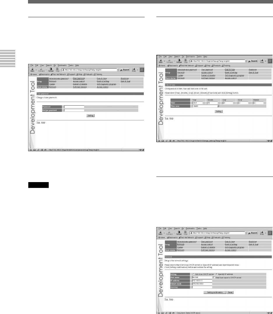
User password
Upon clicking “User password”, the following
screen is displayed. This screen is utilized to
change the user password used to log in to the
system.
Enter the desired password in the “Password” and
“Retype Password” fields. Click “Setting” to
complete the configuration.
Caution
• For security purposes, be sure to change the default
password.
• The password must be a combination of both letters and
numeric characters. Passwords consisting of all lowercase,
all uppercase or all numeric characters are not allowed.
• A password may be seven or eight characters long.
Passwords fewer than seven characters long are not allowed.
Also, if nine or more characters are entered, only the first
eight characters are set as the password.
• If an error is made in entering the password, or the values
entered into the “Password” and “Retype password” fields
do not match, an error message is displayed. If this occurs,
enter the password again.
Date & time
Upon clicking “Date & time”, the following
screen is displayed. This screen is used to
configure the date, time and time zone.
Enter values for the year, month, day and time,
and select the time zone. Click “Setting” to
complete the configuration.
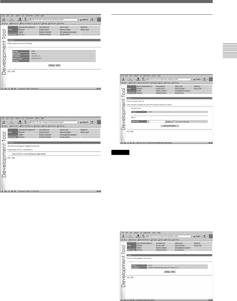
Network
Upon clicking “Network”, the following screen is
displayed. This screen is used to change the
method for obtaining an IP address and to change
the values required for network configuration.
If you want to change the network settings, enter
the new network settings in the appropriate fields
in this screen and then click “Setting
confirmation”. The following confirmation screen
is then displayed.
Setting up
Setting up
Preparing to use the unit
21
Setting up
Click “Setting” to begin processing the settings.
After the configuration is set, the following
screen is displayed.
Modify the network connection mode as needed,
and access the URL displayed on the screen.
Setting up
Update
Upon clicking “Update”, the following screen is
displayed. This screen is used to update the
software required by the unit.
1Place the files to be updated in the
appropriate directories on the
development PC, and click “Update”.
The following screen appears.
Caution
Upon clicking “Setting confirmation” (see the step below),
the versions of files that are already installed and the versions
of the update files are checked to confirm whether the update
files are more recent and to confirm the dependency
relationships between files.
This check is not performed if “No version checking” is
selected. It is recommended that the default setting (“Check
versions”) be used.
2Enter the path to the file to be
updated, and click “Setting
confirmation”.
The following screen is displayed, and the
contents of the update file are displayed.
Preparing to use the unit
22 Setting up
Setting up
3Verify the contents of the files, and
click “Setting”.
The installation will begin.
If the contents are incorrect, click “Back” to
make corrections.
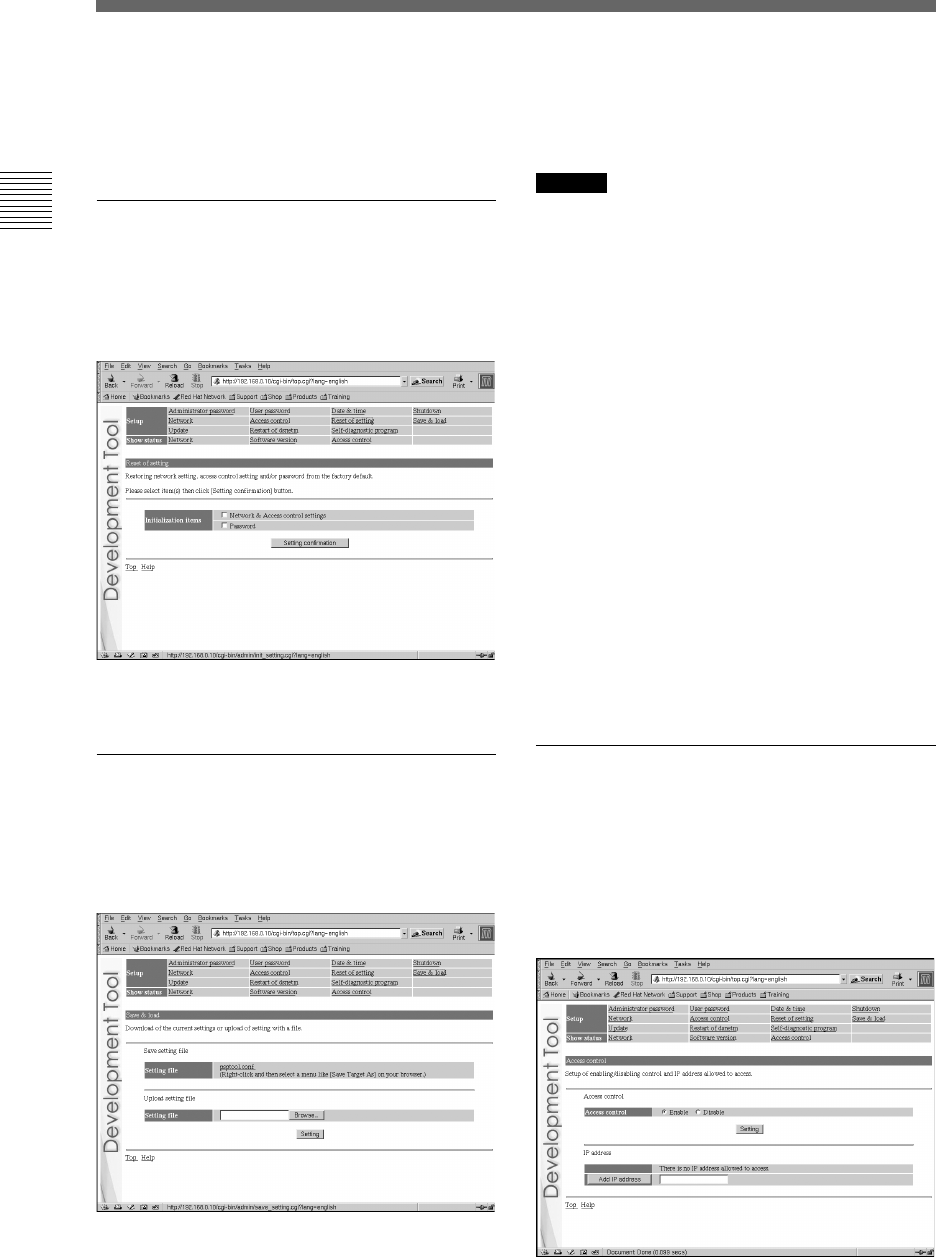
Reset of setting
Upon clicking “Reset of setting”, the following
screen is displayed. This screen is used to restore
the factory default network settings and
administrator password.
Select the setting(s) to be initialized and click
“Setting confirmation” to complete initialization.
Save & load
Upon clicking “Save & load”, the following
screen is displayed. This screen is used to save
the settings and to synchronize the settings with
the unit.
To save the unit’s settings on the
development PC:
Right-click on “psptool.conf” and then select
“Save Target As” or “Save Link As”.
Caution
This procedure may vary depending on the web browser used.
For details, refer to the instructions for the web browser.
To configure the unit using settings
saved on the development PC:
1Check that the IP address defined in
the development PC’s settings file is
the same as the IP address assigned
to the unit.
If the IP address defined in the settings file
and the unit’s IP address are different, use a
text editor to change the IP address in the
settings file of the development PC.
2Click “Browse” and select a file to use
for configuring the unit.
3Click “Setting”.
The settings will be saved on the unit, and
the information will be modified.
Access control
Upon clicking “Access control”, the following
screen is displayed. This screen is used to
configure the PCs that will be allowed to access
dsnet.
“dsnet” is a program package for operating the
unit.
Preparing to use the unit
23
Setting up
Setting up
To deactivate access control:
1Select “Disable”, and click “Setting”.
This allows access from a PC that has been
configured with any IP address.
To activate access control:
1Select “Enable”, and click “Setting”.
This allows access only from a PC that has
been configured with one of the set IP
addresses.
2Enter the IP address to be registered,
and then click “Add IP address”.
This registers the IP address to which access
is permitted.
Click on “Delete” next to an IP address that
has already been registered to delete that
address.
Caution
Enter an IP address using one of the following formats:
• xxx.xxx.xxx.xxx (xxx = 0-255)
• xxx.xxx.xxx.xxx/yy (xxx = 0-255, yy = 0-32)
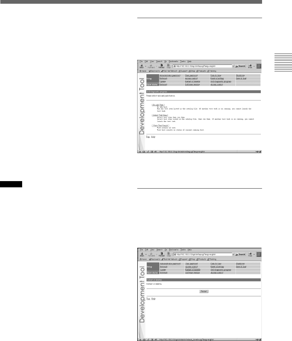
Self-diagnostic program
Upon clicking “Self-diagnostic program”, the
following screen is displayed. This screen is used
to perform a variety of self-diagnostic tests.
1Click on the process to be performed.
The test will begin.
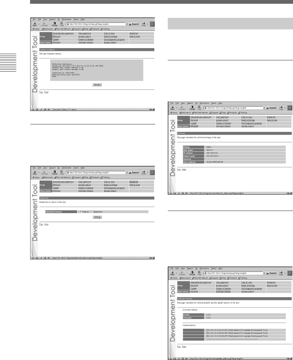
Restart of dsnetm
“dsnetm” is a program used to communicate
between the TCP/IP sockets on the unit and a
host PC.
Upon clicking “Restart of dsnetm”, the following
screen is displayed.
Click “Restart” to restart dsnetm and display the
restart status. After completing the restart, the
following screen is displayed.
Preparing to use the unit
24
Shutdown
Upon clicking “Shutdown”, the following screen
is displayed. This screen is used to reboot or shut
down the unit.
To reboot:
1Select “Reboot” and click “Setting”.
The reboot process will begin. It will take a
few minutes to complete.
To shutdown:
1Select “Shutdown” and click
“Setting”.
This starts the termination process. The
power will be automatically turned off and
the unit will enter standby mode. The power
can also be turned off (thereby putting the
unit into standby mode) by pressing the
on/standby button on the front of the unit.
Setting up
Showing status
Click on the items to the right of “Show status”
to verify the settings.
Network
Upon clicking “Network”, the following screen is
displayed. This screen allows the user to verify
the unit's network settings.
Software version
Upon clicking “Software version”, the following
screen is displayed. This screen displays the
versions of the software packages installed on the
unit and allows the user to verify the unit's update
history.
Setting up
Preparing to use the unit
25
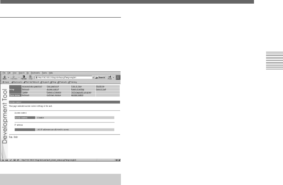
Access control
Upon clicking “Access control”, the following
screen is displayed. This screen lists the dsnet
access control status and the IP addresses that
have been granted access. This allows the user to
verify this information.
Usage notice
For this product, the debugger (dstdb) reset
command cannot be used when the power/hold
switch of the controller is in the hold position.
Make sure that the controller’s power/hold switch
is not in the hold position when operating the
debugger.
Setting up
Setting up

Appendices
26
Chapter3
Appendices
The power does not turn on.
tCheck that the AC adaptor and the AC power cord are securely connected.
The unit cannot be accessed over the network while in use.
tCheck that the power indicator lights up in green to verify that the unit is turned on.
tCheck that the network cable is securely connected.
tCheck that the unit's settings have not been changed by other PCs. Contact your network
administrator for assistance.
When network settings are modified, the unit can no longer be accessed.
tThe network setting may not be correct.
Check the settings displayed on the connected controller. If no settings are displayed on the
controller, disconnect and reconnect the power. The settings will then be displayed on the
controller.
About checking settings
Check that you can access the currently connected network using the values for IP address/subnet mask
that have been configured. For details, please consult your network administrator.
To check whether the development computer and the unit are correctly communicating, start the ping
command from the development computer. For details regarding the use of the ping command, see the
“About the ping command” section below, or refer to the instruction manual supplied with the
development computer.
Also, by pressing the network initialise button, you can return the IP address settings to their factory
default state.
About the ping command
If your development PC’s operating system supports the “ping” command, enter the ping
command as shown below.
# ping (the IP address of the unit)
Troubleshooting
Troubleshooting

Appendices
27
When network communications are functioning, you will see information like the following at a
fixed interval:
PING 192.168.0.10 (192.168.0.10): 56(84) data bytes
64 bytes from 192.168.0.10: icmp_seq=0
ttl=64 time=0.1 ms
64 bytes from 192.168.0.10: icmp_seq=1
ttl=64 time=0.1 ms
64 bytes from 192.168.0.10: icmp_seq=2
ttl=64 time=0.1 ms
(continued below)
When network communications are not functioning, the information will stop after the following:
PING 192.168.0.10 (192.168.0.10): 56 data bytes
If the display appears as shown above, check the following items:
• Is the network cable securely connected to the network connector on the unit?
• Is the network cable securely connected to the hub?
• Is the network cable securely connected to the development PC?
• Do the network settings of the development PC match those of the unit?
After checking the above items, start the ping command from the development PC. Then check
the indicator next to the network connector on the rear of the unit.
• When the indicator flashes orange:
The communications are functioning properly.
• When the indicator is not turned on:
The communications are not functioning properly. This may be due to disconnected
cables, damaged connections, or a unit malfunction.
The unit cannot be accessed, even though five minutes have elapsed since it was
turned on.
tCheck that the power indicator lights up in green.
If so,
there may be a problem with the network cable or the connected hub. Change the network cable
or hub, or contact your network administrator for assistance.
Troubleshooting
Troubleshooting

Appendices
28
Specifications
Main unit (DTP-T1000 A)
Compatible discs
CD-ROM / CD-R / DVD-ROM / DVD-R /
UMDTM
Power
Input voltage DC IN 19.5V
Power consumption 5A
Operating environment
Operating temperature 10°C - 35°C
Operating humidity 30% - 70%
(not condensed)
Dimensions (excluding protrusions)
Development tool 100 x 280 x 298 mm
Controller 170 x 74 x 23 mm
(w/h/d)
Weight
Development tool 5.0 kg or less
Controller 190 ± 30 g
(excluding cables)
Processor
Dedicated processor (max 333 MHz)
Built-in memory
64 MB (fixed)
Built-in peripherals
Communication processor (300 MHz)
External interfaces
USB connector x 1
Memory Stick DuoTM slot x 1
Controller connector x 1
Foot switch connector x 1
Headset connector x 1
RF (extension) connector x 1
Aerial x 1
(For wireless LAN IEEE 802.11b)
Network connector x 1
(100 BASE-TX/10 BASE-T)
VGA connector x 1
(Analog RGB, D-SUB, 15-pin)
AUDIO OUT (audio output) connector x 1
(RCA pin)
Dedicated connector for servicing x 1
(For use by service personnel only.)
Extension connector x 1
(Devices other than those designated
cannot be used.)
Wireless LAN channels
USA and Canada 1-11 ch.
Europe 1-13 ch.
AC adaptor (DTP-H100)
Power
Input voltage AC 100 - 240V (±10%)
Output voltage DC 19.5 V
Rated frequency 50/60Hz (±2%)
Power consumption 1.6A (100V), 0.7A
(240V)
External dimensions
160 x 38 x 80 mm
(w/h/d)
Weight
Approx. 570 g
Supplied accessories
Instruction manual x 1
AC power cord for use in Oceania x 1
AC power cord for use in Europe x 1
AC power cord for use in Korea x 1
AC power cord for use in the UK x 1
AC power cord for use in the USA and
Canada x 1
AC adaptor x 1
Controller x 1
(With controller-interface cable [1.5 m])
Foot switch [1.9 m] x 1
RFI filter for use in Europe, Oceania and
Korea x 1
Fitting band for use in Europe, Oceania and
Korea x 1
Design and specifications are subject to
change without notice.
Specifications

Appendices
29
R&TTE Directive "Informal DoC" statement
For customers in Europe
Language
Dutch
Dutch
English
Finnish
French
German
Greek
Italian
Portuguese
Spanish
Swedish
"Informal DoC"
Undertegnede Sony Computer Entertainment Inc. erklærer herved, at følgende
udstyr DTP-T1000 overholder de væsentlige krav og øvrige relevante krav i direktiv
1999/5/EF. For yderligere information gå ind på følgende hjemmeside:
http://www.compliance.sony.de/
Hierbij verklaart Sony Computer Entertainment Inc. dat het toestel DTP-T1000 in
overeenstemming is met de essentiële eisen en de andere relevante bepalingen
van richtlijn 1999/5/EG. Nadere informatie kunt u vinden op:
http://www.compliance.sony.de/
Hereby, Sony Computer Entertainment Inc. declares that this DTP-T1000 is in
compliance with the essential requirements and other relevant provisions of
Directive 1999/5/EC. For details, please access the following URL:
http://www.compliance.sony.de/
Sony Computer Entertainment Inc. vakuuttaa täten että DTP-T1000 tyyppinen laite
on direktiivin 1999/5/EY oleellisten vaatimusten ja sitä koskevien direktiivin muiden
ehtojen mukainen. Halutessasi lisätietoja, käy osoitteessa:
http://www.compliance.sony.de/
Par la présente Sony Computer Entertainment Inc. déclare que l’appareil
DTP-T1000 est conforme aux exigences essentielles et aux autres dispositions
pertinentes de la directive 1999/5/CE. Pour toute information complémentaire,
veuillez consulter l’URL suivante: http://www.compliance.sony.de/
Hiermit erklärt Sony Computer Entertainment Inc. dass sich dieser/diese/dieses
DTP-T1000 in Übereinstimmung mit den grundlegenden Anforderungen und den
anderen relevanten Vorschriften der Richtlinie 1999/5/EG befindet. Weitere
Informationen erhältlich unter: http://www.compliance.sony.de/
Με την παρούσα η Sony Computer Entertainment Inc. δηλώνει τι DTP-T1000
συµµορφώνεται προς της ουσιώδεις απαιτήσεις και της λοιπές σχετικές
διατάξεις της οδηγίας 1999/5/EK. Για λεπτοµέρειες παρακαλούµε πως
ελένξετε την ακλουθη σελίδα του διαδικτύου:
http://www.compliance.sony.de/
Con la presente Sony Computer Entertainment Inc. dichiara che questo
(DTP-T1000) è conforme ai requisiti essenziali ed alle altre disposizioni pertinenti
stabilite dalla direttiva 1999/5/CE. Per ulteriori dettagli, si prega di consultare il
seguente URL: http://www.compliance.sony.de/
Sony Computer Entertainment Inc. declara que este DTP-T1000 está conforme
com os requisitos essenciais e outras provisões da Directiva 1999/5/CE. Para mais
informacoes, por favor consulte a seguinte URL: http://www.compliance.sony.de/
Por medio de la presente Sony Computer Entertainment Inc. declara que el
(DTP-T1000) cumple con los requisitos esenciales y cualesquiera otras
disposiciones aplicables o exigibles de la Directiva 1999/5/CE. Para mayor
información, por favor consulte el siguiente URL: http://www.compliance.sony.de/
Härmed intygar Sony Computer Entertainment Inc. att denna DTP-T1000 står I
överensstämmelse med de väsentliga egenskapskrav och övriga relevanta
bestämmelser som framgår av direktiv 1999/5/EG. För ytterligare information gå in
på följande hemsida: http://www.compliance.sony.de/
R&TTE Directive "Informal DoC" statement

Appendices
30
This product is supplied pursuant to and subject to the terms of the tool loan agreement with Sony
Computer Entertainment Inc. or its affiliates. Other than as expressly set forth by SCEI and/or any of its
affiliates, except to the extent prohibited by applicable laws, SCEI and/or any of its affiliates shall not be
liable for any damages, including special, incidental or consequential damages, or fees arising out of the
use or inability to use this product.
Limitations of liability
Limitations of liability

Appendices
31

Contact information:
Japan
3rd Party Relations Division
Sony Computer Entertainment Inc.
7-1-1 Akasaka, Minato-ku,
Tokyo 107-0052 Japan
TEL: +81-3-6438-8635 (direct)
Korea
Developer Support
Sony Computer Entertainment Korea Inc.
14Fl. Koosan Tower, 3250, Bangbae2-Dong
Seocho-Gu, Seoul, #137-853 Korea
E-mail: ps2_support@scek.co.kr
TEL: +82-2-6230-3596 (direct)
United Kingdom (Europe)
Technology Group
Sony Computer Entertainment Europe
25 Golden Square
London W1F 9LD UK
TEL: +44-207859-5777 (direct)
http://www.scee.sony.co.uk/
USA
Developer Support
Sony Computer Entertainment America
919 East Hillsdale Boulevard, 2nd Floor
Foster City, CA 94404-2175 USA
TEL: +1-650-655-5566 (direct)
FAX: +1-650-655-5511 (direct)
Without obtaining the consent of the owner, no part of the content of this document may be copied, pursuant
to the provisions of the Copyright Act.
“” is a registered trademark and “ ” and “UMD” are trademarks of Sony Computer
Entertainment Inc.
“SONY” and “ ” are registered trademarks and “Memory Stick Duo”, “Memory Stick PRO Duo” and “ ”
are trademarks of Sony Corporation.
© 2004 Sony Computer Entertainment Inc. All rights reserved.
This product may fall within the scope of national export control legislation.
You must comply fully with the requirements of such legislation and of all other applicable laws of any
jurisdiction in relation to this product.
Printed in Japan