Sony Group J20H084AC WLAN Module User Manual J20H084 00
Sony Corporation WLAN Module J20H084 00
User Manual.pdf
1
Customer Name: Sony Corporation
Project Name WiFi+BT module
Approval Sheet Rev. 1.0
Foxconn Part No. J20H084.00
Sony Part No.
Prepared by Reviewed by Approved by
Clon Liu Eddie Huang
Ambit Microsystems (Shanghai) LTD.
No 1925, Nanle Road Songjiang Export
Processing Zone Shanghai, China
Tel :86-21-61206688 Ext:22165
FAX:86-21-57749230
Approval Sheet of
J20H084ac

2
CONTENTS
1 REVISION HISTORY ..................................................................... 4
2 MANUFACTURING INFORMATION ........................................................ 5
3 PRODUCT OVERVIEW ................................................................... 6
3.1 APPLICATION SCOPE .................................................................... 6
3.2 REGULATION OF EACH COUNTRIES ...................................... 錯誤! 尚未定義書籤。
4 MODULE HARDWARE OVERVIEW ........................................................ 7
4.1 BLOCK DIAGRAM ....................................................................... 7
4.2 FEATURES ............................................................................ 7
4.3 INTERFACE AND CONNECTOR ............................................................. 7
5 ELECTRICAL SPECIFICATION ............................................................ 9
5.1 ABSOLUTE MAXIMUM RATING ............................................................. 9
5.2 RECOMMENDED OPERATING RATING ....................................................... 9
5.3 DC CHARACTERISTICS .................................................................. 9
5.4 ESD INFORMATION ..................................................................... 9
5.5 ENVIRONMENT STORAGE CONDITION ....................................................... 9
6 RF SPECIFICATION .................................................................... 10
6.1 IEEE802.11B ........................................................................ 10
6.2 IEEE802.11G ........................................................................ 11
6.3 IEEE 802.11N HT20 .................................................................. 12
6.4 IEEE 802.11A ........................................................................ 14
6.5 IEEE 802.11AN HT20 ................................................................. 15
6.6 IEEE 802.11AN HT40 ................................................................. 16
6.7 IEEE 802.11AC VHT20 ................................................................ 17
6.8 IEEE 802.11AC VHT40 ................................................................ 18
6.9 IEEE 802.11AC VHT80 ................................................................ 19
6.10 BLUETOOTH 3.0 ....................................................................... 20
6.11 ANTENNA ELECTRICAL SPECIFICATION..................................................... 22
7 MECHANICAL SPECIFICATIONS......................................................... 23
7.1 SHIELDING COVER DIMENSION ........................................................... 23
7.2 PCB ASSEMBLY DIMENSION ............................................................. 25
7.3 MOUNT POSITION OF MATERIALS ....................................... 錯誤! 尚未定義書籤。
8 SCHEMATICS ......................................................... 錯誤! 尚未定義書籤。
9 LAYOUT PATTERN .................................................... 錯誤! 尚未定義書籤。
9.1 MAIN PCB LAYOUT .................................................. 錯誤! 尚未定義書籤。
9.2 ANTENNA PCB LAYOUT ............................................... 錯誤! 尚未定義書籤。
10 BOM (BILL OF MATERIALS) ............................................ 錯誤! 尚未定義書籤。
11 LABEL INFORMATION ................................................. 錯誤! 尚未定義書籤。
11.1 MAC ID LABEL (FOR PVT, MP) ........................................ 錯誤! 尚未定義書籤。
12 PACKAGE AND STACK INFORMATION ................................. 錯誤! 尚未定義書籤。
12.1 CARTON ASSY ..................................................... 錯誤! 尚未定義書籤。
12.2 PALLET ASSY ...................................................... 錯誤! 尚未定義書籤。
12.3 TRAY ID LABEL ..................................................... 錯誤! 尚未定義書籤。

3
12.4 CARTON LABEL ..................................................... 錯誤! 尚未定義書籤。
12.5 PALLET LABEL ...................................................... 錯誤! 尚未定義書籤。
13 RELIABILITY TEST PLAN .............................................. 錯誤! 尚未定義書籤。
14 ESD TEST REPORT ................................................... 錯誤! 尚未定義書籤。
15 NOTIFICATION ........................................................ 錯誤! 尚未定義書籤。

4
1 Revision History
Date Document revision Change Description
2014/02/19 1.0
Initial release

5
2 Manufacturing Information
Manufacture Country:
Made in China
Manufacturer:
Ambit Microsystems (Shanghai) LTD.
Manufacture Address:
No 1925, Nanle Road Songjiang Export Processing Zone Shanghai, China

6
3 Product Overview
The J20H084.00 802.11a/b/g/n/ac 2X2 and BT4.0+LE module provides wireless modem
functionality utilizing direct sequence spread spectrum and OFDM/CCK technology. This
module is based on MTK MT7662U solution .It fully complies with IEEE 802.11n,IEEE
802.11 a/b/g and ,IEEE 802.11 ac standards, Bluetooth v2.1+EDR,
V4.0 standard, offering feature-rich wireless connectivity at high standards, and delivering
reliable, cost-effective throughput from an extended distance. Optimized RF architecture
and baseband algorithms provide superb performance and low power consumption.
Intelligent MAC design deploys a high efficient DMA engine and hardware data processing
accelerators which offloads the host processor.
3.1 Application scope
The wireless LAN is compliant to IEEE 802.11n,IEEE 802.11 a/b/g and IEEE 802.11 ac
standards.
Channel Spacing
2.4GHz -> 5MHz, 5GHz-> 20MHz (BW on 20MHz),40MHz (BW on 40MHz)
Data rate:
1, 2, 5.5, 11Mbps for 802.11b;
6, 9, 12, 18, 24, 36, 48 and 54Mbps for 802.11a/g;
MCS0(6.5Mbps)~MCS7(72.2Mbps) for 802.11n HT20 mode (single chain);
MCS0(13Mbps)~MCS15(144.4Mbps) for 802.11n HT20 mode (dual chains);
MCS0(13Mbps)~MCS7(150Mbps) for 802.11n HT40 (5G only) mode (single chain);
MCS0(26Mbps)~MCS15(300Mbps) for 802.11n HT40 (5G only) mode (dual chains);
MCS0(6.5Mbps)~MCS8(86.7Mbps) for 802.11ac VHT20 mode (single chain);
MCS0(13Mbps)~MCS8(173.3Mbps) for 802.11ac VHT20 mode (dual chains);
MCS0(13.5Mbps)~MCS9(200Mbps) for 802.11ac VHT40 mode (single chain);
MCS0(27Mbps)~MCS9(400Mbps) for 802.11ac VHT40 mode (dual chains);
MCS0(32.5Mbps)~MCS9(433.3Mbps) for 802.11ac VHT80 mode (single chain);
MCS0(65Mbps)~MCS9(866.6Mbps) for 802.11ac VHT80 mode (dual chains);
BT:
The BT Module is compliant to Bluetooth 4.0 and EDR standard:
Carrier Frequency: 2402MHz ~ 2480 MHz
Carrier Spacing: 1.0MHz (classic), 2MHz (LE)
Duplexing: TDD
Modulation: FHSS
1Mbps (GFSK), 2Mbps (π/4-DQPSK), 3Mbps (8DPSK),LE (GFSK)
7
4 Module Hardware Overview
4.1 Block Diagram
NA
4.2 Features
♦ IEEE802.11a/b/g/n/ac (2X2) based on MTK MT7662U solution.
♦ Support BT4.0+LE
♦ USB 2.0 Interface, High and Full Speeds supported.
♦ Module is powered by the host with a 3.3V +/- 5% supply.
♦ External PCB printed antennas.
♦ 4 layers through hole PCB design with FR4 material
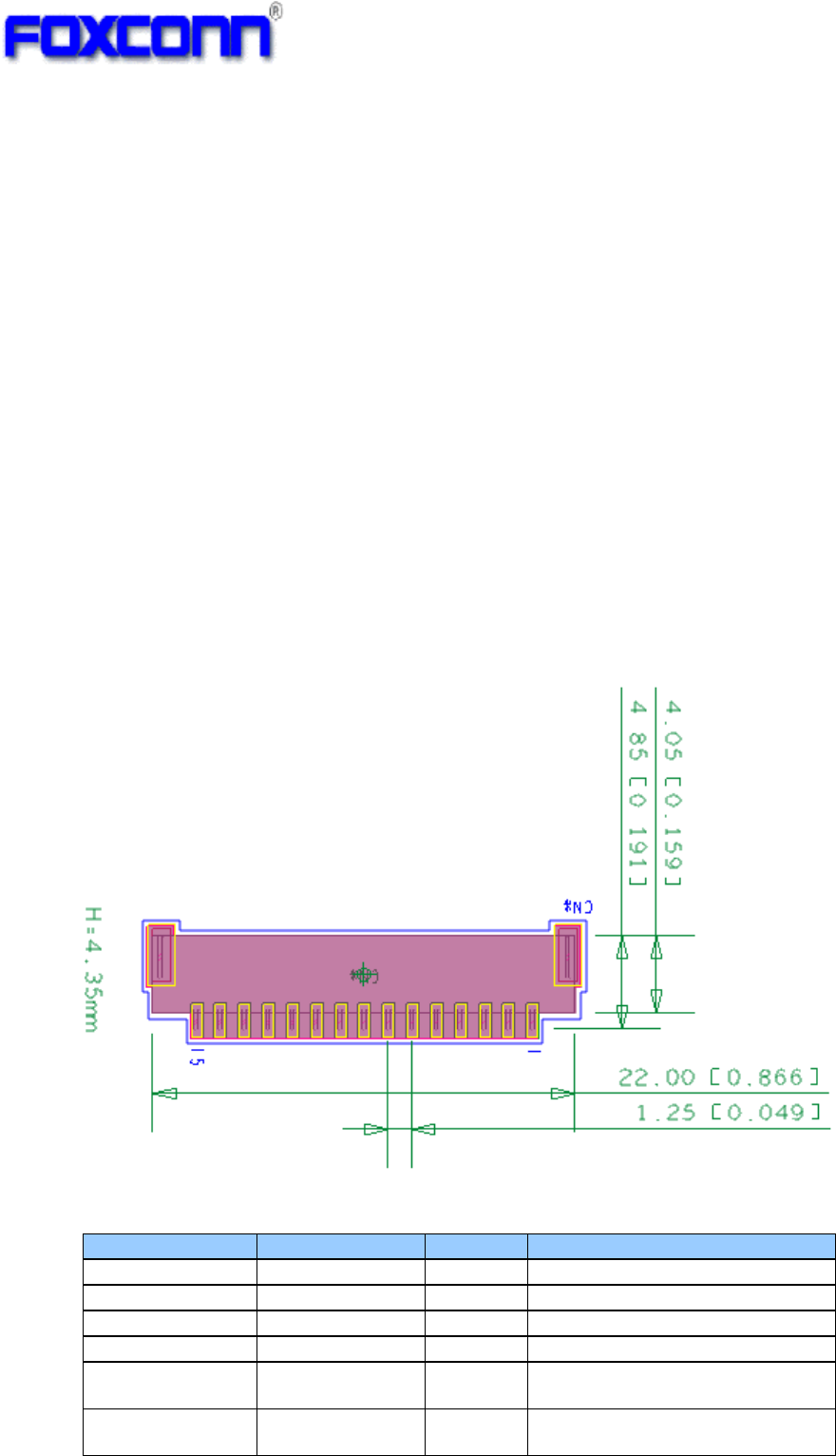
4.3 Interface and Connector
♦ Pin definition:
♦ Vendor: JST
♦ Vendor P/N: SM15B-GHS-TB
Pin Number Symbol Name Status Pin definition
1 UART_RX Input UART_RX for BT
2 UART_TX Output UART_TX for BT
3 GND - Ground
4 RST_L Input “L”-drive reset signal input from Host.
5 WOW_H Output Wake on WLAN signal output.
“H”-drive is hoped when awake Host.
6 WOBT_H Output Wake on Bluetooth signal output.
“H”-drive is hoped when awake Host.

8
(old: Host_wake)
7 GND - Ground
8 DM I/O USB_DATA-
9 DP I/O USB_DATA+
10 GND - Shield Ground
11 VSYNC Input 3D Video sync Signal
12 GND - Ground
13 GND - Ground
14 VCC PWR DC 3.3V
15 VCC PWR DC 3.3V
S1 Ground
S2 Ground
9
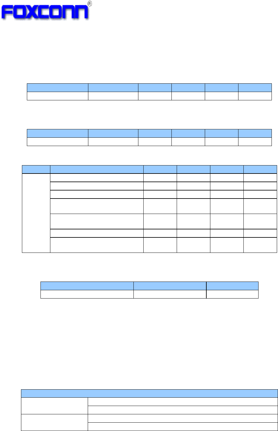
5 Electrical Specification
5.1 Absolute maximum rating
Element Symbol Min Typ Max Unit
DC supply voltage UV+ 3.3
3.65 (V)
5.2 Recommended operating rating
Element Symbol Min Typ Max Unit
DC supply voltage UV+ 2.97 3.3
3.63 (V)
5.3 DC Characteristics
Symbol Parameter Min Typ. Max Unit
UV+
Supply voltage 2.97 3.3 3.63 (V)
2.412GHz Tx Current(1M/16dBm) 470 (mA)
2.412GHz Tx Current(MCS0/15dBm) 440 (mA)
5.18GHz Tx
Current(6M/13Bm/HT20)
580 (mA)
5.19GHz Tx
Current(MCS0/13dBm/HT40)
560 (mA)
Rx Current - (mA)
5.21GHz Tx
Current(MCS9/11dBm/VHT80)
450 (mA)
5.4 ESD Information
Mode Level Unit
HBM +/-1000 V
5.5 Environment Storage Condition
Environment condition
Temperature Operating Temperature: -10 deg.C ~60 deg.C
Storage Temperature: -40 deg.C ~85 deg.C
Humidity Operating Humidity: 20% ~90%
Storage Humidity: 20% ~90%
10
6 RF Specification
6.1 IEEE802.11b
Items Contents
Specification IEEE802.11b
Mode DSSS / CCK
Channel CH1 to CH13
Data rate 1, 2, 5.5, 11Mbps
TX Characteristics Min. Typ. Max. Unit
1. Power Levels (Calibrated)
1) Target Power@1Mbps 14.5 16 17.5 dBm
2) Target Power@2Mbps
14.5 16 17.5 dBm
3) Target Power@5.5Mbps
14.5 16 17.5 dBm
4) Target Power@11Mbps
14.5 16 17.5 dBm
2. Spectrum Mask @15dBm
1) fc-33MHz < f < fc-22MHz - - -50 dBr
2) fc-22MHz < f < fc-11MHz - - -30 dBr
3) fc+11MHz < f < fc+22MHz - - -30 dBr
4) fc+22MHz < f < fc+33MHz - - -50 dBr
3. Frequency Error@25℃ -5 - +5 ppm
4 Modulation Accuracy(EVM)@15dBm
1) 1Mbps - -10 dB
2) 2Mbps - -10 dB
3) 5.5Mbps - -10 dB
4) 11Mbps - -10 dB
RX Characteristics Min. Typ. Max. Unit
5 Minimum Input Level Sensitivity
1) 1Mbps (FER≦8%) - -95 -91 dBm
2) 2Mbps (FER≦8%) --91 -88 dBm
3) 5.5Mbps (FER≦8%) --90 -87 dBm
4) 11Mbps (FER≦8%) --89 -85 dBm
6 Maximum Input Level (FER≦8%) -10 0 - dBm

11
6.2 IEEE802.11g
Items Contents
Specification IEEE802.11g
Mode OFDM
Channel CH1 to CH13
Data rate 6, 9, 12, 18, 24, 36, 48, 54Mbps
TX Characteristics Min. Typ. Max. Unit
1. Power Levels (Calibrated)
1) Target Power@6Mbps
13.5 15 16.5 dBm
2) Target Power@9Mbps
13.5 15 16.5 dBm
3) Target Power@12Mbps
13.5 15 16.5 dBm
4) Target Power@18Mbps
13.5 15 16.5 dBm
5) Target Power@24Mbps
12.5 14 15.5 dBm
6) Target Power@36Mbps
12.5 14 15.5 dBm
7) Target Power@48Mbps
12.5 14 15.5 dBm
8) Target Power@54Mbps
12.5 14 15.5 dBm
2. Spectrum Mask @15dBm
1) at fc +/- 11MHz - - -20 dBr
2) at fc +/- 20MHz - - -28 dBr
3) at fc > +/-30MHz - - -40 dBr
3 Modulation Accuracy(EVM)@15dBm
1) 6Mbps - - -5 dB
2) 9Mbps - - -8 dB
3) 12Mbps - - -10 dB
4) 18Mbps - - -13 dB
5) 24Mbps - - -16 dB
6) 36Mbps - - -19 dB
7) 48Mbps - - -22 dB
8) 54Mbps - -28 -25 dB
4 Frequency Error@25℃ -5 - +5 ppm
RX Characteristics Min. Typ. Max. Unit
5 Minimum Input Level Sensitivity
1) 6Mbps (PER <10%) - -92 -83 dBm
2) 9Mbps (PER < 10%) - -91 -81 dBm
3) 12Mbps (PER < 10%) - -90 -79 dBm
4) 18Mbps (PER < 10%) - -87 -77 dBm
5) 24Mbps (PER < 10%) - -85 -75 dBm
6) 36Mbps (PER < 10%) - -80 -73 dBm
7) 48Mbps (PER < 10%) - -77 -71 dBm
8) 54Mbps (PER < 10%) - -75 -69 dBm
6 Maximum Input Level (PER < 10%) -20 -11 - dBm

12
6.3 IEEE 802.11n HT20
Items Contents
Specification IEEE802.11n HT20
Mode OFDM
Channel CH1 and CH11~CH13
Data rate (MCS index) MCS0/1/2/3/4/5/6/7
TX Characteristics Min. Typ. Max. Unit
1. Power Levels (Calibrated)
1) Target Power@MCS0
13.5 15 16.5 dBm
2) Target Power@ MCS1
13.5 15 16.5 dBm
3) Target Power@ MCS2
13.5 15 16.5 dBm
4) Target Power@ MCS3
13.5 15 16.5 dBm
5) Target Power@ MCS4
12.5 14 15.5 dBm
6) Target Power@ MCS5
12.5 14 15.5 dBm
7) Target Power@ MCS6
12.5 14 15.5 dBm
8) Target Power@ MCS7
12.5 14 15.5 dBm
2. Spectrum Mask @14dBm
1) at fc +/- 11MHz - - -20 dBr
2) at fc +/- 20MHz - - -28 dBr
3) at fc > +/-30MHz - - -45 dBr
3. Modulation Accuracy(EVM)@14dBm
1) MCS0 - - -5 dB
2) MCS1 - - -10 dB
3) MCS2 - - -13 dB
4) MCS3 - - -16 dB
5) MCS4 - - -19 dB
6) MCS5 - - -22 dB
7) MCS6 - - -25 dB
8) MCS7 - - -28 dB
4. Frequency Error@25℃ -5 - +5 ppm
RX Characteristics Min. Typ. Max. Unit
5. Minimum Input Level Sensitivity
1) MCS0 (PER < 10%) - -91 -81 dBm
2) MCS1 (PER < 10%) - -89 -79 dBm
3) MCS2 (PER < 10%) - -87 -77 dBm
4) MCS3 (PER < 10%) - -84 -75 dBm
5) MCS4 (PER < 10%) - -80 -73 dBm
6) MCS5 (PER < 10%) - -75 -71 dBm
7) MCS6 (PER < 10%) - -74 -69 dBm
8) MCS7 (PER < 10%) - -72 -67 dBm
6. Maximum Input Level (PER < 10%) -20 -10 - dBm

13
Items Contents
Specification IEEE802.11n HT20
Mode OFDM
Channel CH2 to CH10
Data rate (MCS index) MCS0/1/2/3/4/5/6/7
TX Characteristics Min. Typ. Max. Unit
1. Power Levels (Calibrated)
1) Target Power@MCS0
13.5 15 16.5 dBm
2) Target Power@ MCS1
13.5 15 16.5 dBm
3) Target Power@ MCS2
13.5 15 16.5 dBm
4) Target Power@ MCS3
13.5 15 16.5 dBm
5) Target Power@ MCS4
12.5 14 15.5 dBm
6) Target Power@ MCS5
12.5 14 15.5 dBm
7) Target Power@ MCS6
12.5 14 15.5 dBm
8) Target Power@ MCS7
12.5 14 15.5 dBm
2. Spectrum Mask @15dBm
1) at fc +/- 11MHz - - -20 dBr
2) at fc +/- 20MHz - - -28 dBr
3) at fc > +/-30MHz - - -45 dBr
3. Modulation Accuracy(EVM)@15dBm
1) MCS0 - - -5 dB
2) MCS1 - - -10 dB
3) MCS2 - - -13 dB
4) MCS3 - - -16 dB
5) MCS4 - - -19 dB
6) MCS5 - - -22 dB
7) MCS6 - - -25 dB
8) MCS7 - - -28 dB
4. Frequency Error@25℃ -5 - +5 ppm
RX Characteristics Min. Typ. Max. Unit
5. Minimum Input Level Sensitivity
1) MCS0 (PER < 10%) - -91 -81 dBm
2) MCS1 (PER < 10%) - -89 -79 dBm
3) MCS2 (PER < 10%) - -87 -77 dBm
4) MCS3 (PER < 10%) - -84 -75 dBm
5) MCS4 (PER < 10%) - -80 -73 dBm
6) MCS5 (PER < 10%) - -75 -71 dBm
7) MCS6 (PER < 10%) - -74 -69 dBm
8) MCS7 (PER < 10%) - -72 -67 dBm
6. Maximum Input Level (PER < 10%) -20 -10 - dBm

14
6.4 IEEE 802.11a
Items Contents
Specification IEEE802.11a
Mode OFDM
Channel CH36 to CH165
Data rate 6, 9, 12, 18, 24, 36, 48, 54Mbps
TX Characteristics Min. Typ. Max. Unit
1. Power Levels (Calibrated)
1) Target Power@6Mbps
11.5 13 14.5 dBm
2) Target Power@9Mbps
11.5 13 14.5 dBm
3) Target Power@12Mbps
11.5 13 14.5 dBm
4) Target Power@18Mbps
11.5 13 14.5 dBm
5) Target Power@24Mbps
10.5 12 13.5 dBm
6) Target Power@36Mbps
10.5 12 13.5 dBm
7) Target Power@48Mbps
10.5 12 13.5 dBm
8) Target Power@54Mbps
10.5 12 13.5 dBm
2. Spectrum Mask @12dBm
1) at fc +/- 11MHz - - -20 dBr
2) at fc +/- 20MHz - - -28 dBr
3) at fc > +/-30MHz - - -40 dBr
3 Modulation Accuracy(EVM)@12dBm
1) 6Mbps - - -5 dB
2) 9Mbps - - -8 dB
3) 12Mbps - - -10 dB
4) 18Mbps - - -13 dB
5) 24Mbps - - -16 dB
6) 36Mbps - - -19 dB
7) 48Mbps - - -22 dB
8) 54Mbps - -28 -25 dB
4 Frequency Error@25℃ -5 - +5 ppm
RX Characteristics Min. Typ. Max. Unit
5 Minimum Input Level Sensitivity
1) 6Mbps (PER <10%) - -92 -83 dBm
2) 9Mbps (PER < 10%) - -91 -81 dBm
3) 12Mbps (PER < 10%) - -90 -79 dBm
4) 18Mbps (PER < 10%) - -87 -77 dBm
5) 24Mbps (PER < 10%) - -85 -75 dBm
6) 36Mbps (PER < 10%) - -80 -73 dBm
7) 48Mbps (PER < 10%) - -77 -71 dBm
8) 54Mbps (PER < 10%) - -75 -69 dBm
6 Maximum Input Level (PER < 10%) -20 -11 - dBm

15
6.5 IEEE 802.11an HT20
Items Contents
Specification IEEE802.11an HT20
Mode OFDM
Channel CH36 to CH165
Data rate (MCS index) MCS0/1/2/3/4/5/6/7
TX Characteristics Min. Typ. Max. Unit
1. Power Levels (Calibrated)
1) Target Power@MCS0
11.5 13 14.5
dBm
2) Target Power@ MCS1
11.5 13 14.5
dBm
3) Target Power@ MCS2
11.5 13 14.5
dBm
4) Target Power@ MCS3
11.5 13 14.5
dBm
5) Target Power@ MCS4
10.5 12 13.5
dBm
6) Target Power@ MCS5
10.5 12 13.5
dBm
7) Target Power@ MCS6
10.5 12 13.5
dBm
8) Target Power@ MCS7
10.5 12 13.5
dBm
2. Spectrum Mask @12dBm
1) at fc +/- 11MHz - - -20 dBr
2) at fc +/- 20MHz - - -28 dBr
3) at fc > +/-30MHz - - -45 dBr
3. Modulation Accuracy(EVM)@12dBm
1) MCS0 - - -5 dB
2) MCS1 - - -10 dB
3) MCS2 - - -13 dB
4) MCS3 - - -16 dB
5) MCS4 - - -19 dB
6) MCS5 - - -22 dB
7) MCS6 - - -25 dB
8) MCS7 - - -28 dB
4. Frequency Error@25℃ -5 - +5 ppm
RX Characteristics Min. Typ. Max. Unit
5. Minimum Input Level Sensitivity
1) MCS0 (PER < 10%) - -91 -81 dBm
2) MCS1 (PER < 10%) - -89 -79 dBm
3) MCS2 (PER < 10%) - -87 -77 dBm
4) MCS3 (PER < 10%) - -84 -75 dBm
5) MCS4 (PER < 10%) - -80 -73 dBm
6) MCS5 (PER < 10%) - -75 -71 dBm
7) MCS6 (PER < 10%) - -74 -69 dBm
8) MCS7 (PER < 10%) - -72 -67 dBm
6. Maximum Input Level (PER < 10%) -20 -10 - dBm

16
6.6 IEEE 802.11an HT40
Items Contents
Specification IEEE802.11an HT40
Mode OFDM
Channel CH38 to CH159
Data rate (MCS index) MCS0/1/2/3/4/5/6/7
TX Characteristics Min. Typ. Max. Unit
1. Power Levels (Calibrated)
1) Target Power@MCS0
10.5 12 13.5 dBm
2) Target Power@ MCS1
10.5 12 13.5 dBm
3) Target Power@ MCS2
10.5 12 13.5 dBm
4) Target Power@ MCS3
10.5 12 13.5 dBm
5) Target Power@ MCS4
10.5 12 13.5 dBm
6) Target Power@ MCS5
10.5 12 13.5 dBm
7) Target Power@ MCS6
10.5 12 13.5 dBm
8) Target Power@ MCS7
10.5 12 13.5 dBm
2. Spectrum Mask @12dBm
1) at fc +/- 21MHz - - -20 dBr
2) at fc +/- 40MHz - - -28 dBr
3) at fc > +/-60MHz - - -45 dBr
3. Modulation Accuracy(EVM)@12dBm
1) MCS0 - - -5 dB
2) MCS1 - - -10 dB
3) MCS2 - - -13 dB
4) MCS3 - - -16 dB
5) MCS4 - - -19 dB
6) MCS5 - - -22 dB
7) MCS6 - - -25 dB
8) MCS7 - - -28 dB
4. Frequency Error@25℃ -5 - +5 ppm
RX Characteristics Min. Typ. Max. Unit
5. Minimum Input Level Sensitivity
1) MCS0 (PER < 10%) - -88 -78 dBm
2) MCS1 (PER < 10%) - -86 -76 dBm
3) MCS2 (PER < 10%) - -84 -74 dBm
4) MCS3 (PER < 10%) - -81 -72 dBm
5) MCS4 (PER < 10%) - -77 -70 dBm
6) MCS5 (PER < 10%) - -72 -68 dBm
7) MCS6 (PER < 10%) - -71 -66 dBm
8) MCS7 (PER < 10%) - -69 -64 dBm
6. Maximum Input Level (PER < 10%) -20 -10 - dBm

17
6.7 IEEE 802.11ac VHT20
Items Contents
Specification IEEE802.11ac VHT20
Mode OFDM
Channel CH36 to CH165
Data rate (MCS index) MCS0/1/2/3/4/5/6/7/8
TX Characteristics Min. Typ. Max. Unit
1. Power Levels (Calibrated)
1) Target Power@MCS0
11.5 13 14.5
dBm
2) Target Power@ MCS1
11.5 13 14.5
dBm
3) Target Power@ MCS2
11.5 13 14.5
dBm
4) Target Power@ MCS3
11.5 13 14.5
dBm
5) Target Power@ MCS4
10.5 12 13.5
dBm
6) Target Power@ MCS5
10.5 12 13.5
dBm
7) Target Power@ MCS6
10.5 12 13.5
dBm
8) Target Power@ MCS7
10.5 12 13.5
dBm
9) Target Power@ MCS8
9.5 11 12.5 dBm
2. Spectrum Mask @11dBm
1) at fc +/- 11MHz - - -20 dBr
2) at fc +/- 20MHz - - -28 dBr
3) at fc > +/-30MHz - - -45 dBr
3. Modulation Accuracy(EVM)@11dBm
1) MCS0 - - -5 dB
2) MCS1 - - -10 dB
3) MCS2 - - -13 dB
4) MCS3 - - -16 dB
5) MCS4 - - -19 dB
6) MCS5 - - -22 dB
7) MCS6 - - -25 dB
8) MCS7 - - -27 dB
9) MCS8 - - -30 dB
4. Frequency Error@25℃ -5 - +5 ppm
RX Characteristics Min. Typ. Max. Unit
5. Minimum Input Level Sensitivity
1) MCS0 (PER < 10%) - -91 -81 dBm
2) MCS1 (PER < 10%) - -89 -79 dBm
3) MCS2 (PER < 10%) - -87 -77 dBm
4) MCS3 (PER < 10%) - -84 -75 dBm
5) MCS4 (PER < 10%) - -80 -73 dBm
6) MCS5 (PER < 10%) - -75 -71 dBm
7) MCS6 (PER < 10%) - -74 -69 dBm
8) MCS7 (PER < 10%) - -72 -67 dBm
8) MCS8 (PER < 10%) - -63 -58 dBm
6. Maximum Input Level (PER < 10%) -20 -10 - dBm

18
6.8 IEEE 802.11ac VHT40
Items Contents
Specification IEEE802.11ac VHT40
Mode OFDM
Channel CH38 to CH159
Data rate (MCS index) MCS0/1/2/3/4/5/6/7/8/9
TX Characteristics Min. Typ. Max. Unit
1. Power Levels (Calibrated)
1) Target Power@MCS0
11.5 13 14.5
dBm
2) Target Power@ MCS1
11.5 13 14.5
dBm
3) Target Power@ MCS2
11.5 13 14.5
dBm
4) Target Power@ MCS3
11.5 13 14.5
dBm
5) Target Power@ MCS4
10.5 12 13.5
dBm
6) Target Power@ MCS5
10.5 12 13.5
dBm
7) Target Power@ MCS6
10.5 12 13.5
dBm
8) Target Power@ MCS7
10.5 12 13.5
dBm
9) Target Power@ MCS8
9.5 11 12.5 dBm
10) Target Power@ MCS9
9.5 11 12.5 dBm
2. Spectrum Mask @11dBm
1) at fc +/- 21MHz - - -20 dBr
2) at fc +/- 40MHz - - -28 dBr
3) at fc > +/- 60MHz - - -45 dBr
3. Modulation Accuracy(EVM)@11dBm
1) MCS0 - - -5 dB
2) MCS1 - - -10 dB
3) MCS2 - - -13 dB
4) MCS3 - - -16 dB
5) MCS4 - - -19 dB
6) MCS5 - - -22 dB
7) MCS6 - - -25 dB
8) MCS7 - - -27 dB
9) MCS8 - - -30 dB
10) MCS9 - - -32 dB
4. Frequency Error@25℃ -5 - +5 ppm
RX Characteristics Min. Typ. Max. Unit
5. Minimum Input Level Sensitivity
1) MCS0 (PER < 10%) - -88 -78 dBm
2) MCS1 (PER < 10%) - -86 -76 dBm
3) MCS2 (PER < 10%) - -84 -74 dBm
4) MCS3 (PER < 10%) - -81 -72 dBm
5) MCS4 (PER < 10%) - -77 -70 dBm
6) MCS5 (PER < 10%) - -72 -68 dBm
7) MCS6 (PER < 10%) - -71 -66 dBm
8) MCS7 (PER < 10%) - -69 -64 dBm
7) MCS8 (PER < 10%) - -64 -59 dBm
8) MCS9 (PER < 10%) - -60 -57 dBm
6. Maximum Input Level (PER < 10%) -20 -10 - dBm

19
6.9 IEEE 802.11ac VHT80
Items Contents
Specification IEEE802.11ac VHT80
Mode OFDM
Channel CH42 to CH155
Data rate (MCS index) MCS0/1/2/3/4/5/6/7/8/9
TX Characteristics Min. Typ. Max. Unit
1. Power Levels (Calibrated)
1) Target Power@ MCS0
11.5 13 14.5
dBm
2) Target Power@ MCS1
11.5 13 14.5
dBm
3) Target Power@ MCS2
11.5 13 14.5
dBm
4) Target Power@ MCS3
11.5 13 14.5
dBm
5) Target Power@ MCS4
10.5 12 13.5
dBm
6) Target Power@ MCS5
10.5 12 13.5
dBm
7) Target Power@ MCS6
10.5 12 13.5
dBm
8) Target Power@ MCS7
10.5 12 13.5
dBm
9) Target Power@ MCS8
9.5 11 12.5 dBm
10) Target Power@ MCS9
9.5 11 12.5 dBm
2. Spectrum Mask @11dBm
1) at fc +/- 41MHz - - -20 dBr
2) at fc +/- 80MHz - - -28 dBr
3) at fc > +/- 120MHz - - -45 dBr
3. Modulation Accuracy(EVM)@11dBm
1) MCS0 - - -5 dB
2) MCS1 - - -10 dB
3) MCS2 - - -13 dB
4) MCS3 - - -16 dB
5) MCS4 - - -19 dB
6) MCS5 - - -22 dB
7) MCS6 - - -25 dB
8) MCS7 - - -27 dB
9) MCS8 - - -30 dB
10) MCS9 - - -32 dB
4. Frequency Error@25℃ -5 - +5 ppm
RX Characteristics Min. Typ. Max. Unit
5. Minimum Input Level Sensitivity
1) MCS0 (PER < 10%) - -80 -75 dBm
2) MCS1 (PER < 10%) - -78 -73 dBm
3) MCS2 (PER < 10%) - -76 -71 dBm
4) MCS3 (PER < 10%) - -74 -69 dBm
5) MCS4 (PER < 10%) - -72 -67 dBm
6) MCS5 (PER < 10%) - -70 -65 dBm
7) MCS6 (PER < 10%) - -68 -63 dBm
8) MCS7 (PER < 10%) - -66 -61 dBm
9) MCS8 (PER < 10%) - -63 -58 dBm
10) MCS9 (PER < 10%) - -59 -54 dBm
6. Maximum Input Level (PER < 10%) -20 -10 - dBm
20
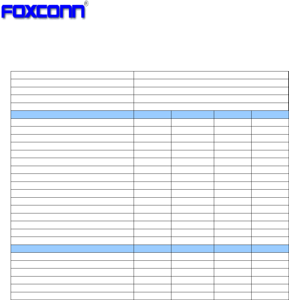
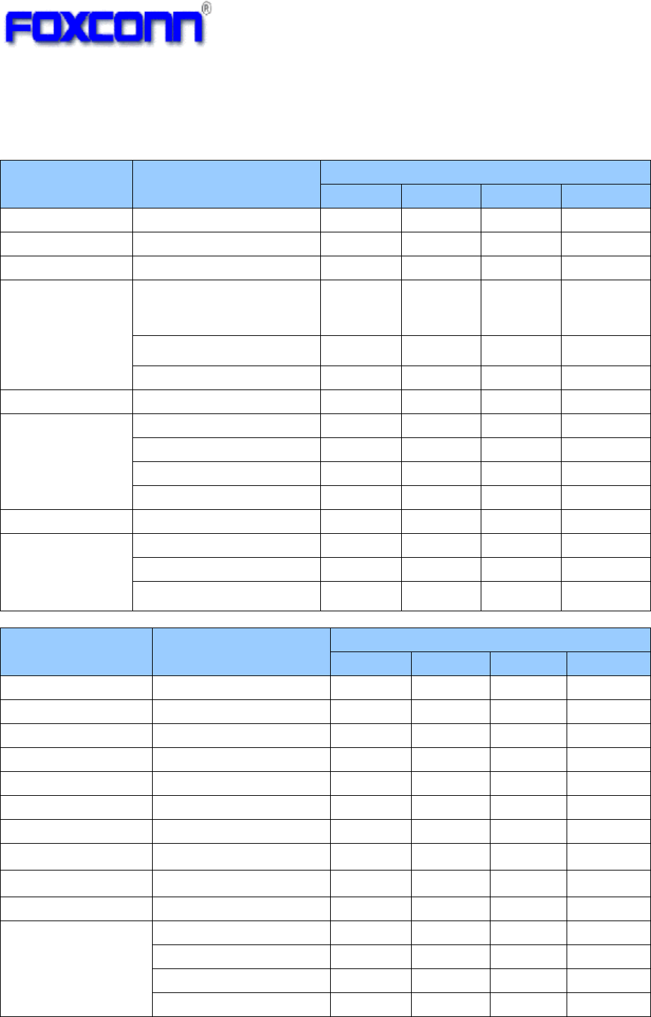
6.10 Bluetooth 3.0
BT specification
BDR TX
PARAMETER DESCRIPTION
PERFORMANCE
MIN TYP MAX Unit
Frequency range 2402 - 2480 MHz
Output power At maximum power output level -1 1 3 dBm
Gain step 2 4 8 dB
Modulation
characteristics
Δf1avg 140 157 175 KHz
Δf2max(For at least 99.9% of allΔ
f2max) 115 140 - KHz
Δf1avg/Δf2avg 0.8 0.98 - KHz
ICFT Initial carrier frequency tolerance -25 25 KHz
Carrier frequency drift
One slot packet(DH1) -25 25 KHz
Three slot packet(DH3) -40 40 KHz
Five slot packet(DH5) -40 40 KHz
Max drift -20 20 KHz/50us
TX output spectrum 20dB bandwidth 922 1000 KHz
In-Band spurious
emission
±2MHz offset -45 -20 dBm
±3MHz offset -48 -40 dBm
>±3MHz offset -48 -40 dBm
BDR RX
PARAMETER DESCRIPTION PERFORMANCE
MIN TYP MAX Unit
Frequency range 2402 - 2480 MHz
Receiver sensitivity BER<0.1% -93.5 -80 dBm
Maximum usable signal BER<0.1% -5 dBm
C/I co-channel (BER<0.1%) Co channel selectivity 4 11 dB
C/I 1MHz (BER<0.1%) Adjacent channel selectivity -14 0 dB
C/I 2MHz (BER<0.1%) 2nd adjacent channel selectivity -42 -30 dB
C/I >=3 MHz (BER<0.1%) 3rd adjacent channel selectivity -49 -40 dB
C/I Image channel
(BER<0.1%) Image channel selectivity -25 -9 dB
C/I Image 1MHz (BER<0.1%) 1MHz adjacent to image channel
selectivity -50 -20 dB
Inter-modulation -13 dBm
Out-of-band blocking
30MHz to 2000MHz -10 dBm
2000MHz to 2399MHz -27 dBm
2498MHz to 3000MHz -27 dBm
3000MHz to 12.75GHz -10 dBm
21
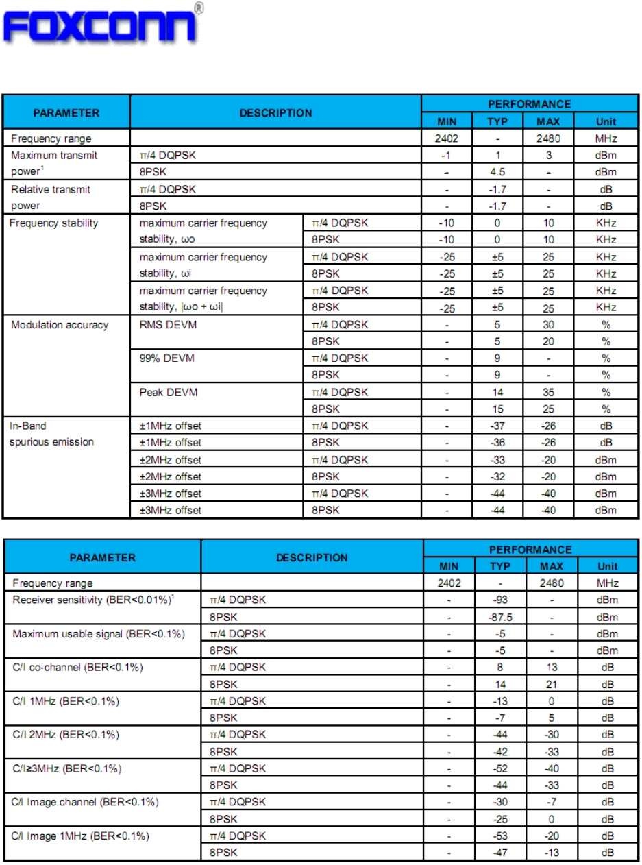
EDR TX
EDR RX
22
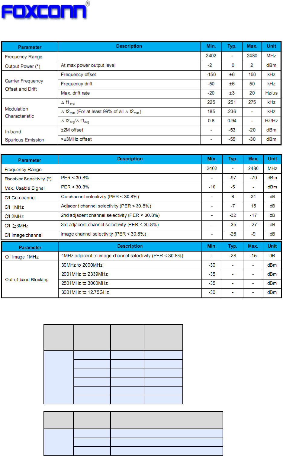
LE TX
LE RX
6.11 Antenna Electrical Specification
WiFi:
Frequency
Ant.1
Peak
Gain (dBi)
Ant.2
Peak Gain
(dBi)
WiFi
antenna
2.40GHz 3.54dBi 3.06dBi
2.45GHz 4.40dBi 3.12dBi
2.50GHz 3.90dBi 3.19dBi
5.15GHz 7.45dBi 7.63dBi
5.45GHz 6.20dBi 6.99dBi
5.85GHz 7.63dBi 7.87dBi
BT:
Frequency Cable Length: 500mm Peak
Gain (dBi)
BT
antenna
2.40GHz 3.45dBi
2.45GHz 3.53dBi
2.50GHz 3.27dBi
23
7 Mechanical Specifications
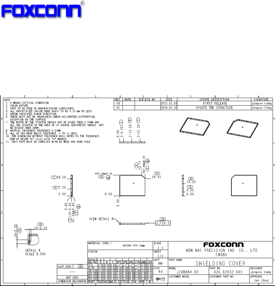
7.1 Shielding Cover Dimension
Dimension (LxWxH): 22.44mm x 27.66mm x 1.5mm
Thickness: 0.2mm
24
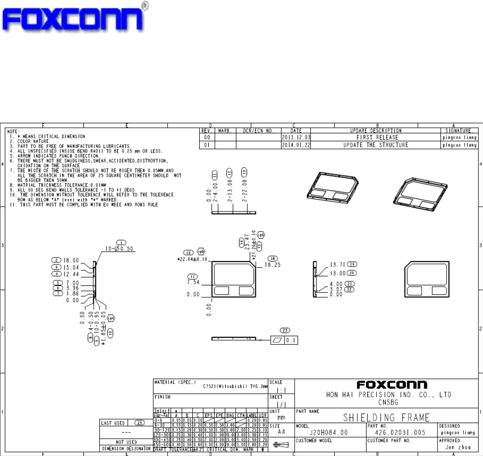
7.2 Shielding frame Dimension
Dimension (LxWxH): 22.04mm x 27.26mm x 1.5mm
Thickness: 0.1mm
25
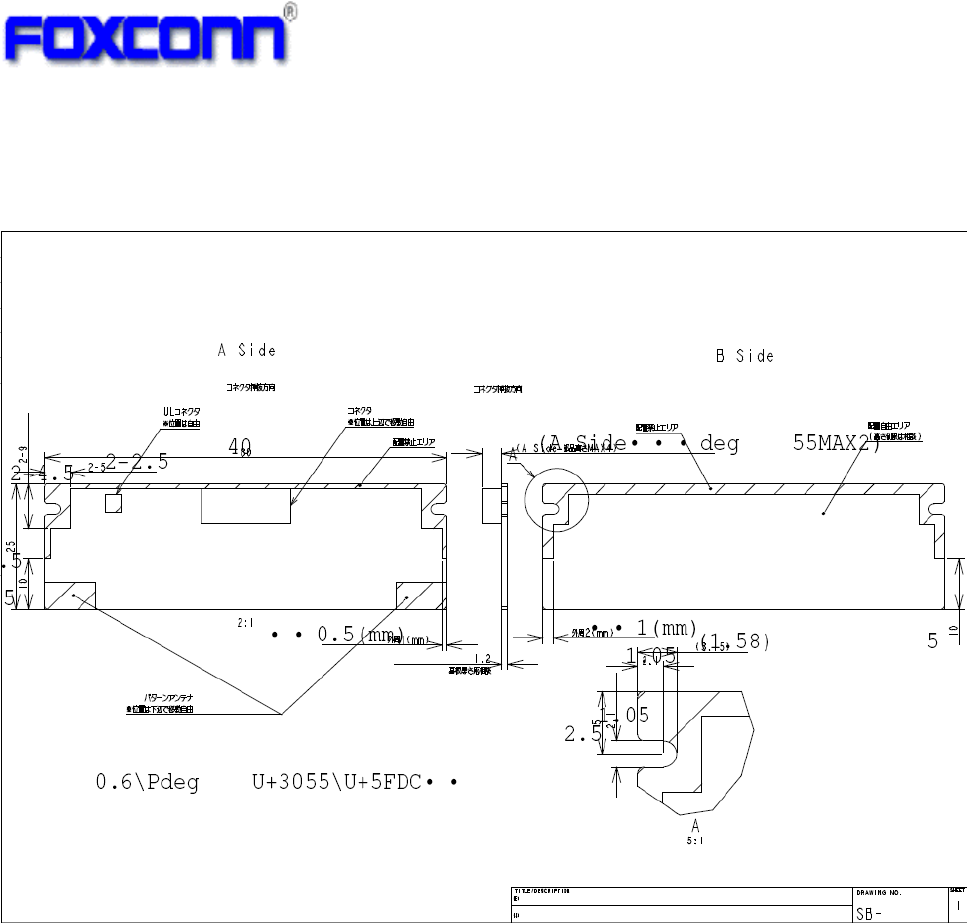
7.3 PCB Assembly Dimension
Dimension (W x Lx H ): 80mmx25mmx1.0mm
PCB: 4 layer FR4 design
Industry Canada statement:
This device complies with RSS-210 of the Industry Canada Rules. Operation is subject to
the following two conditions: (1) This device may not cause harmful interference, and (2)
this device must accept any interference received, including interference that may cause
undesired operation.
Ce dispositif est conforme à la norme CNR-210 d'Industrie Canada applicable aux
appareils radio exempts de licence. Son fonctionnement est sujet aux deux conditions
suivantes: (1) le dispositif ne doit pas produire de brouillage préjudiciable, et (2) ce
dispositif doit accepter tout brouillage reçu, y compris un brouillage susceptible de
provoquer un fonctionnement indésirable.
Radiation Exposure Statement:
This equipment complies with IC radiation exposure limits set forth for an uncontrolled
environment. This equipment should be installed and operated with minimum distance
20cm between the radiator & your body.
Déclaration d'exposition aux radiations:
Cet équipement est conforme aux limites d'exposition aux rayonnements IC établies pour
un environnement non contrôlé. Cet équipement doit être installé et utilisé avec un
minimum de 20 cm de distance entre la source de rayonnement et votre corps.
This device is intended only for OEM integrators under the following conditions:
(For module device use)

!
37!
1) The antenna must be installed such that 20 cm is maintained between the antenna and
users, and
2) The transmitter module may not be co-located with any other transmitter or antenna.
As long as 2 conditions above are met, further transmitter test will not be required.
However, the OEM integrator is still responsible for testing their end-product for any
additional compliance requirements required with this module installed.
Cet appareil est conçu uniquement pour les intégrateurs OEM dans les conditions
suivantes: (Pour utilisation de dispositif module)
1) L'antenne doit être installée de telle sorte qu'une distance de 20 cm est respectée entre
l'antenne et les utilisateurs, et
2) Le module émetteur peut ne pas être coïmplanté avec un autre émetteur ou antenne.
Tant que les 2 conditions ci-dessus sont remplies, des essais supplémentaires sur
l'émetteur ne seront pas nécessaires. Toutefois, l'intégrateur OEM est toujours
responsable des essais sur son produit final pour toutes exigences de conformité
supplémentaires requis pour ce module installé.
IMPORTANT NOTE:
In the event that these conditions can not be met (for example certain laptop configurations
or co-location with another transmitter), then the Canada authorization is no longer
considered valid and the IC ID can not be used on the final product. In these
circumstances, the OEM integrator will be responsible for re-evaluating the end product
(including the transmitter) and obtaining a separate Canada authorization.
NOTE IMPORTANTE:
Dans le cas où ces conditions ne peuvent être satisfaites (par exemple pour certaines
configurations d'ordinateur portable ou de certaines co-localisation avec un autre
émetteur), l'autorisation du Canada n'est plus considéré comme valide et l'ID IC ne peut
pas être utilisé sur le produit final. Dans ces circonstances, l'intégrateur OEM sera chargé
de réévaluer le produit final (y compris l'émetteur) et l'obtention d'une autorisation distincte
au Canada.
End Product Labeling
This transmitter module is authorized only for use in device where the antenna may be
installed such that 20 cm may be maintained between the antenna and users. The final
end product must be labeled in a visible area with the following: “Contains IC:
2878DJ20H084AC”.
Plaque signalétique du produit final
Ce module émetteur est autorisé uniquement pour une utilisation dans un dispositif où
l'antenne peut être installée de telle sorte qu'une distance de 20cm peut être maintenue
entre l'antenne et les utilisateurs. Le produit final doit être étiqueté dans un endroit visible
avec l'inscription suivante: "Contient des IC: 2878D- J20H084AC".
Manual Information To the End User
The OEM integrator has to be aware not to provide information to the end user regarding
how to install or remove this RF module in the user’s manual of the end product which
integrates this module.
The end user manual shall include all required regulatory information/warning as show in
this manual.
Manuel d'information à l'utilisateur final
L'intégrateur OEM doit être conscient de ne pas fournir des informations à l'utilisateur final
quant à la façon d'installer ou de supprimer ce module RF dans le manuel de l'utilisateur
du produit final qui intègre ce module.
Le manuel de l'utilisateur final doit inclure toutes les informations réglementaires requises
et avertissements comme indiqué dans ce manuel.
2878D.J20H084AC”.
2878D.J20H084AC”.

!
38!
Federal Communication Commission Interference Statement
This device complies with Part 15 of the FCC Rules. Operation is subject to the
following two conditions: (1) This device may not cause harmful interference, and
(2) this device must accept any interference received, including interference that
may cause undesired operation.
This equipment has been tested and found to comply with the limits for a Class B
digital device, pursuant to Part 15 of the FCC Rules. These limits are designed to
provide reasonable protection against harmful interference in a residential
installation. This equipment generates, uses and can radiate radio frequency energy
and, if not installed and used in accordance with the instructions, may cause
harmful interference to radio communications. However, there is no guarantee that
interference will not occur in a particular installation. If this equipment does cause
harmful interference to radio or television reception, which can be determined by
turning the equipment off and on, the user is encouraged to try to correct the
interference by one of the following measures:
- Reorient or relocate the receiving antenna.
- Increase the separation between the equipment and receiver.
- Connect the equipment into an outlet on a circuit different from that
to which the receiver is connected.
- Consult the dealer or an experienced radio/TV technician for help.
FCC Caution: Any changes or modifications not expressly approved by the party
responsible for compliance could void the user's authority to operate this equipment.
This transmitter must not be co-located or operating in conjunction with any other
antenna or transmitter.
Radiation Exposure Statement:
This equipment complies with FCC radiation exposure limits set forth for an
uncontrolled environment. This equipment should be installed and operated with
minimum distance 20cm between the radiator & your body.
This device is intended only for OEM integrators under the following conditions:
1) The antenna must be installed such that 20 cm is maintained between the antenna
and users, and 2) The transmitter module may not be co-located with any other transmitter
or antenna.
As long as 2 conditions above are met, further transmitter test will not be required.
However, the OEM integrator is still responsible for testing their end-product for any
additional compliance requirements required with this module installed
IMPORTANT NOTE: In the event that these conditions can not be met (for example
certain laptop configurations or co-location with another transmitter), then the FCC
authorization is no longer considered valid and the FCC ID can not be used on the
final product. In these circumstances, the OEM integrator will be responsible for
reevaluating
the end product (including the transmitter) and obtaining a separate FCC
authorization.
End Product Labeling
This transmitter module is authorized only for use in device where the antenna may be
installed such that 20 cm may be maintained between the antenna and users. The
final end product must be labeled in a visible area with the following: “Contains FCC

!
39!
ID: MCLJ20H084AC”. The grantee's FCC ID can be used only when all FCC compliance
requirements are met.
Manual Information To the End User
The OEM integrator has to be aware not to provide information to the end user
regarding how to install or remove this RF module in the user’s manual of the end
product which integrates this module.
The end user manual shall include all required regulatory information/warning as show
in this manual.
For Taiwan ᤞΚ!(ሽॾጥࠫ୴᙮ᕴޗࠌش)
ᆖীڤᎁᢞٽհ܅פ୴᙮ሽᖲΔॺᆖױΔֆΕᇆࢨࠌشृ݁լᖐ۞᧢ޓ᙮!
ΕףՕפࢨ᧢ޓૠհࢤ֗פ౨Ζ!
܅פ୴᙮ሽᖲհࠌشլᐙଆڜ٤֗եឫٽऄຏॾΙᆖ࿇ڶեឫွழΔᚨم!
ܛೖشΔࠀޏ۟ྤեឫழֱᤉᥛࠌشΖছႈٽऄຏॾΔਐࠉሽॾऄࡳ܂ᄐհྤᒵ!
ሽຏॾΖ܅פ୴᙮ሽᖲႊݴ࠹ٽऄຏॾࢨՠᄐΕઝᖂ֗᠔᛭شሽंᘿ୴ࢤሽᖲໂհ!
եឫΖ!
Note: 1. ءᑓิ࣍࠷ᎁᢞ৵ലࠉࡳ࣍ᑓิء᧯ᑑقᐉ᧭ٽᑑ᧘!2. ߓอᐗᚨ࣍ؓ!
Ղᑑقψءขփܶ୴᙮ᑓิ: XXXyyyLPDzzzz-x (NCC ID) ωڗᑌ!
!
!
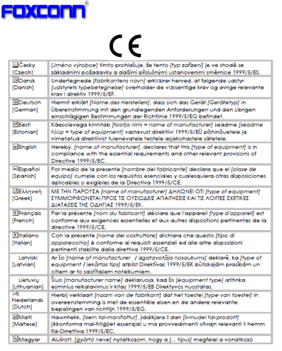
Europe – EU Declaration of Conformity
ThisdevicecomplieswiththeessentialrequirementsoftheR&TTEDirective1999/5/EC.Thefollowingtestmethodshavebeen
appliedinordertoprovepresumptionofconformitywiththeessentialrequirementsoftheR&TTEDirective1999/5/EC:
EN609501:2006+A11:2009+A1:2010+A12:2011
SafetyofInformationTechnologyEquipment
EN62311:2008
Assessmentofelectronicandelectricalequipmentrelatedtohumanexposurerestrictionsforelectromagneticfields(0
Hz300GHz)
(IEC62311:2007(Modified))
EN300328V1.7.1:2006
ElectromagneticcompatibilityandRadiospectrumMatters(ERM);WidebandTransmissionsystems;Datatransmission
equipmentoperatinginthe2,4GHzISMbandandusingspreadspectrummodulationtechniques;HarmonizedENcovering
essentialrequirementsunderarticle3.2oftheR&TTEDirective
EN3014891V1.8.1:2008
ElectromagneticcompatibilityandRadioSpectrumMatters(ERM);ElectroMagneticCompatibility(EMC)standardforradio
equipmentandservices;Part1:Commontechnicalrequirements
EN30148917V2.1.12009
ElectromagneticcompatibilityandRadiospectrumMatters(ERM);ElectroMagneticCompatibility(EMC)standardforradio
equipmentandservices;Part17:Specificconditionsfor2,4GHzwidebandtransmissionsystemsand5GHzhighperformance
RLANequipment
NationalAuthoritieswereinformedaccordingtoArticle6.4ofFrequencyNotification.
SpecialRequirementsareconsidered.TheproductislabeledwithCEMarking.
ID: AK8J20H084AC”.
29