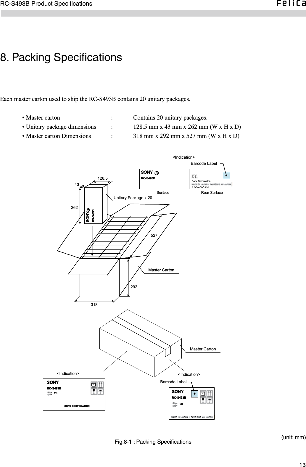
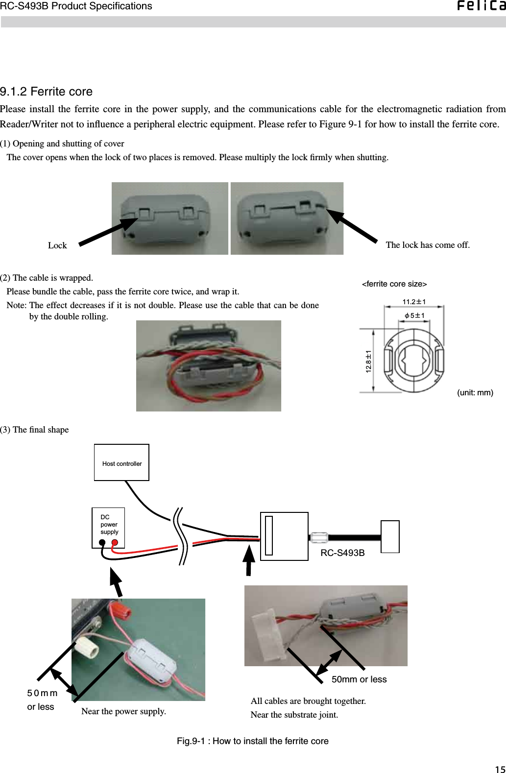
Sony Group RCS493B Contactless IC Card Reader / Writer User Manual

Sony Corporation Contactless IC Card Reader / Writer

User Manual

Version 0.91No.M440-E0.9-10Product Specifications(Preliminary)RC-S493BReader/WriterNote : This document is preliminary and subject to change without notice.
lntroductionThis document  describes the  major features  and specifications  of Sony’s  RC-S493B Reader/Writer.  The following terms used in this document refer to the products or equipment as per the descriptions to the right.  Card    :  An IC card designed in conformity with Sony's FeliCa contactless IC card system.   Reader/writer  :   A device used to read and write cards in Sony's FeliCa contactless IC card system.  Controller  :    An external computer,  gate controller  or  equivalent that is directly connected  to a Reader/Writer using a specific cable.This document does not provide information about pre-operation setup for the Reader/Writer, nor does it contain details of individual commands. Please refer to the “Reader/Writer Command Reference Manual”.  To  ensure optimal  implementation into  your system,  refer  also to  the “RC-S460/490  Series Reader/Writers  Installation Requirements and Evaluation Methods”.Safety Information and CautionFor customers in USA and CanadaYou are cautioned that any changes or  modifications not expressly approved in this manual  could void your authority to operate this equipment.This device complies  with  part 15  of FCC  Rules and  RSS-Gen  of IC  Rules. Operation  is subject  to  the following two conditions: (1) this device may not cause harmful interference, and (2) this device must accept any interference received, including interference that may cause undesired operation.This equipment has  been tested and found to comply with  the limits for a  Class B digital device, pursuant to Part 15 of the  FCC  Rules.  These  limits  are  designed  to  provide  reasonable  protection  against  harmful  interference  in  a  residential installation. This equipment generates, uses, and  can radiate radio frequency energy and, if  not installed and used in accordance with the instructions, may cause harmful interference to radio communications. However, there is no guarantee that interference  will not  occur in a  particular installation.  If this  equipment does  cause harmful  interference to  radio or television reception, which can be determined by turning the equipment off and on, the user is encouraged to try to correct the interference by one or more of the following measures:- Reorient or relocate the receiving antenna.- Increase the separation between the equipment and receiver.- Connect the equipment into an outlet on a circuit different from that to which the receiver is connected.- Consult the dealer or an experienced radio/TV technician for help.The interface cable with ferrite core must be used with the equipment in order to comply with the limits for a digital device pursuant to Subpart B of Part 15 of FCC Rules.This Class B digital apparatus complies with Canadian ICES-003.Cet appareil numérique de la classe B est conforme à la norme NMB-003 du Canada.
- FeliCa is a contactless IC card technology developed by Sony Corporation.- FeliCa is a trademark of Sony Corporation.- All names of companies and products contained herein are trademarks or registered trademarks of the respective companies.- No part of this manual may be copied, or reproduced in any form, without the prior consent of Sony Corporation.- Information in this manual is subject to change without notice. For customers in EuropeSony hereby declares that this equipment is in compliance with the essential requirements and other relevant provisions of European Directive 1999/5/EC.To  obtain a  copy  of the  declaration  of conformity  (DoC)  with  the R&TTE  Directive,  please  access the  following URL address.http://www.compliance.sony.de/This product complies with EN 55022 Class B and EN 55024, for use in following areas: residential, commercial and light industrial.This product has been tested and found compliant with the limits set out in the EMC Directive for using connection cables not longer than 3 meters (9.8 feet).Emissions from this inductive device could cause interference to nearby receivers of other radio services.
Contents1. Major Functions and Features ....................................................................................................................12. Basic Specifications ...................................................................................................................................22.1 Communication Specifications ............................................................................................................................22.1.1 Reader/Writer to Card Wireless Communication Specifications  ........................................................................... 22.1.2 Reader/Writer to Controller Communication Specifications .................................................................................. 32.2 Electrical Specifications ......................................................................................................................................42.3 General Specifications .........................................................................................................................................43. External Dimensions ..................................................................................................................................54. Internal Structure .......................................................................................................................................85. Connection Specifications ..........................................................................................................................96. Basic Reader/Writer Operation/Data Flow ..............................................................................................116.1 Transaction Overview ........................................................................................................................................116.1.1 Communication Protocol ...................................................................................................................................... 116.1.2 ACK Packet ........................................................................................................................................................... 116.1.3 Mutual Authentication .......................................................................................................................................... 117. Security ....................................................................................................................................................128. Packing Specifications .............................................................................................................................139. Precautions ...............................................................................................................................................149.1 Precautions for Installation ................................................................................................................................149.1.1 Reader/Writer ........................................................................................................................................................ 149.1.2 Ferrite core ............................................................................................................................................................ 159.2 Handling Precautions ........................................................................................................................................1610. Command List ........................................................................................................................................17Glossary .......................................................................................................................................................19
RC-S493B Product Specifications1. Major Functions and FeaturesThe RC-S493B Reader/Writer read and write data to and from FeliCa-enabled contactless IC cards. Because operation is contactless, they exhibit no wear due to dirt or friction and maintenance is reduced to a minimum. Major features• Environmentally friendly, with lead-free soldering used for the board. The board also contains no halogen.• Equipped with a high-security LSI conforming to ISO/IEC 15693 EAL4.
RC-S493B Product Specifications 2. Basic SpecificationsThe RC-S493B Reader/Writer is composed of an antenna, an RF/control board and an antenna cable for connecting them to each other. 2.1  Communication Specifications                                                2.1.1 Reader/Writer to Card Wireless Communication Specifications Wireless communication between the Reader/Writer and the card is based on the following specifications.   Maximum communication distance :  30 mm              (when using a card in the RC-S860 Series/RC-S880 Series/RC-S833)            20 mm (when using RC-S890)            *  The communication distance varies depending on the peripheral environment. The figures  shown above  are  the  results of measurements performed in an  ideal  environment unaffected by electromagnetic waves and metallic substances.  Wireless communication system  :  Load modulation system*1  Data transfer rate     :  211.875 kbps or 423.75 kbps*2  Carrier frequency     :  13.56 MHz  Modulation system    :  Transmission - ASK (modulation ratio 11±3%)            Reception - ASK  Bit coding system    :  Transmission - Manchester coding            Reception – Manchester coding  Modulation bandwidth    :  ±300 kHz (at -30 dB carrier level)  Electric field strength (Emissive electric field strength of fundamental wave, 13.56MHz)          :  Less than 300 μV/m (at 10m distance)             (Complies with the regulations in Clause 46-2 Section 1-1 of the Enforcement Ordinance of the Radio Law of Japan.)  Communication system    :  Half-duplex communication, CRC-CCITT  Compatible cards/tokens            FeliCa cards    :  RC-S860 Series (RC-S860, RC-S862, RC-S863, RC-S864)            RC-S880 Series (RC-S880)            RC-S833      * One card can be used at a time.         Tokens      :  RC-S890 Series (RC-S890) *1 Complies with ISO/IEC 18092 (212 kbps Passive Mode) standards.   *2 Available only when the card or mobile device to be used also accommodates the 423.75 kbps transfer mode.
RC-S493B Product SpecificationsFig.2-1 : Maximum Communication Distance to the Card* The antenna of the card or mobile phone is placed in parallel with the antenna of the Reader/Writer,with their centers aligned along the same vertical axis.CardReader/WriterMaximumCommunication DistanceAntenna Surface2.1.2 Reader/Writer to Controller Communication SpecificationsThe Reader/Writer communicates with the controller in accordance with the following specifications.  Signal level    :   CMOS 5V  Communication speed  :  7.2 kbps ~ 1228.8 kbps            (7.2,  8.192,  9.6,  14.4,  19.2,  28.8, 38.4, 57.6,  115.2,  230.4,  460.8,  921.6  and 1228.8 kbps selectable by software, default setting: 115.2 kbps)  Start bit      :   1 bit  Data bits     :   8 bits  Parity bit    :   none  Stop bit      :   1 bit  Flow control    :   None  Communication system  :  Half-duplex communication  Physical connection  :   3-wire connection (Rx, Tx, GND)
RC-S493B Product Specifications 2.2  Electrical SpecificationsTable 2-1: Electrical SpecificationsMIN TYP MAX Unit ConnectorPower supply voltage - 12V system - 11.5 12.0 16.0 VDC12VCurrent consumption (during normal operation) - 12V system - 80 mAAllowable power supply ripple 100*1 mVPower supply voltage - 5V system - 4.75 5.0 5.25 VDC5VCurrent consumption (during normal operation) - 5V system - 100 mACurrent consumption (when rewriting firmware) - 5V system -*2 70 mAAllowable power supply ripple 100*1 mV*1  Peak to peak *2 Communication with the card is interrupted.2.3  General Specifications  Usage environment (No condensation or icing)  Storage environment (No condensation or icing)0℃ 70℃60% RH or less-30℃0℃ 40℃ 50℃20%~90%RH 50% RH or lessPerformance assurance temperature/humidity 0℃ 40℃ 60℃20%~90%RH-10℃* Performance assurance: The guaranteed communication distance to the card is maintained.   Operation assurance: Communication with the card remains possible.Operation assurance temperature/humidity50% RH or less  MTBF    :  More than 100,000 hours        Condition: Usage environment, GF (ground level, fixed)         (Measured in conformity with MIL-HDBK-217 NOTICE2 for evaluating the reliability of electronic components.)  Mass    :  Approx. 110g
RC-S493B Product Specifications3. External Dimensions  Dimensions       Control board      Board size    :  71.8 (±0.4)* mm x 63.6 (±0.4) mm x 12 (±0.5) mm        * These figures contain the hole part for the product installation.    Antenna assembly      Board size    :  50 (±0.5) mm x 25 (±0.5) mm x 1 (±0.2) mm        Thickness    :  Less than 5 mm               (including ferrite and metal plates but not the connector)   Antenna cable      Length      :  125 mm ±3 mm (including the connector housing)       Width      :  12.8 mm ±1 mm (Size in ferrite core)   Mounting hole      RF/control board   :  Ø3.3 mm x 2 (M3 compatible, see Fig. 3-1.)      Antenna     :  None
RC-S493B Product Specifications (unit: mm)Fig.3-1 : RF/Control Board63.618.812111116.532-φ3.332.24-R2122071.871.855812±0.54p Connector connection hole
RC-S493B Product Specifications(unit: mm)Fig.3-2 : AntennaUUUU9125010253.7 2.54.64.314PIN・Antenna Board6ConnectorMetal PlateFerrite+1-0.5+0.5-1+1-0.5+1-0.5(unit: mm)Fig.3-3 : Antenna cable125±3 mm12.8±1 mm
RC-S493B Product Specifications 4. Internal StructureThe RC-S493B Reader/Writers is configured as in Fig. 4-1.Fig.4-1 : Reader/Writer Schematic DiagramVoltageRegulatorDataTransmitterDataReceiverCoilAntennaOscillator12VRC-S940VoltageRegulator5V
RC-S493B Product Specifications5. Connection SpecificationsThis chapter provides details of interfacing with the controller. (Refer to Table 5-1 on the next page.)The RC-S493B  Reader/Writer employs the  HKP-40M1 40-pin interface connector  manufactured by HONDA TSUSHIN KOGYO CO., LTD. As shown in Fig. 3-1, the connector is located on the bottom edge of the RF/control board. Connector pins are 2.54 mm in pitch and gold-plated. Also, they are arranged in double rows and numbered from the lower row’s leftmost pin (pin No. 1). During installation, particular attention must be paid to their polarities.
RC-S493B Product Specifications0 Table 5-1: CN2 Connector Pin AssignmentPin No. Designation Function Remarks1 DC12V DC power supply terminal For RF amplifier2 NC No Connection3 DC12V DC power supply terminal  For RF amplifier4 NC No Connection5 NC No Connection6 GND Ground terminal7 NC No Connection8 GND Ground terminal 9 - (Reserved) Do not connect the signal line.10 SI Serial data I/O (CMOS 5V) 11 - (Reserved) Do not connect the signal line.12 SO Serial data I/O (CMOS 5V) 13 - (Reserved) Do not connect the signal line.14 NC No Connection15 - (Reserved) Do not connect the signal line.16 MODE No need to connect for normal operation. When loading a program, be sure to apply a high level voltage (5V) to this pin prior to powering up the RF/control board.17 - (Reserved) Do not connect the signal line.18 - (Reserved) Do not connect the signal line.19 - (Reserved) Do not connect the signal line.20 - (Reserved) Do not connect the signal line.21 - (Reserved) Do not connect the signal line.22 - (Reserved) Do not connect the signal line.23 - (Reserved) Do not connect the signal line.24 - (Reserved) Do not connect the signal line.25 - (Reserved) Do not connect the signal line.26 - (Reserved) Do not connect the signal line.27 - (Reserved) Do not connect the signal line.28 - (Reserved) Do not connect the signal line.29 - (Reserved) Do not connect the signal line.30 - (Reserved) Do not connect the signal line.31 - (Reserved) Do not connect the signal line.32 - (Reserved) Do not connect the signal line.33 NC No Connection34 DC5V DC power supply terminal 35 NC No Connection36 DC5V DC power supply terminal37 GND Ground terminal 38 NC No Connection39 GND Ground terminal40 NC No Connection
RC-S493B Product Specifications6. Basic Reader/Writer Operation/Data Flow6.1  Transaction Overview                                                      6.1.1 Communication ProtocolThe Reader/Writer returns ACK upon successful reception of a command packet. It remains unresponsive if reception fails.Fig.6-1 : Communication Protocol and Packet StructureController Reader/WriterCommand PacketACKResponse PacketACK00h 00h ffh LEN LCS PD0 PD1 ・・・ PDn DCS 00hPreambleStart of Packet CodePacket LengthPacket Length ChecksumCommand or Response CodePacket DataPacket Data ChecksumPostamble6.1.2 ACK PacketThe ACK packet is formatted as follows.00h 00h ffh 00h ffh 00hLEN LCS(Packet data and DCS are not included.)6.1.3 Mutual AuthenticationMutual authentication* is the process of two units authenticating each other. Between a controller and Reader/Writer, this is performed by using the following elements in order to provide protection against fraudulent access, tampering, spoofing and other illicit data manipulation.   1.  Two 56-bit keys  2.  ISO9798-2 compliant authentication model comprising three paths  3.  Encryption algorithm*  For  more information about mutual authentication and encryption,  refer to the  “Reader/Writer Command Reference Manual”.
RC-S493B Product Specifications 7. SecurityIllicit data access and tampering that may occur during communication are serious security risks to any IC card system. To safeguard against such risks, the Reader/Writer encrypts and  decrypts data transmitted to and received from the card, whereas the same is performed by the controller for security protection of data communication between the controller and the Reader/Writer. More specifically, the following must be observed to ensure secure system operation. 1)  Communication between the controller and the Reader/Writer must always be performed in the encryption mode. Data flows  through the  communication path when  the Reader/Writer  communicates with  the card in  accordance with the command  received  from the controller.  The  path must therefore  be  protected by turning  on  the encryption mode  and performing mutual authentication between the controller and the Reader/Writer.2)  Access keys used for mutual authentication between the controller and the Reader/Writer must be updated periodically. Leakage of key information can result in surreptitious  use or divulgation of eavesdropped data,  and in the worst case, may  seriously affect the operation  of  the entire  system.  Do  not continue  to  use factory-preset  access keys  (Kar,  Kbr) without changing their values, especially for mutual authentication in actual applications.      The access keys can be changed by using the Change Reader/Writer Access Key command.     For more details, refer to the “Reader/Writer Command Reference Manual”.Fig.7-1 : Schematic Diagram of Security ProtectionController Reader/Writer Card1. Mutual Authentication (Kar, Kbr)2. Card Access Keys3. Mutual Authentication(Using Card Access Keys)
RC-S493B Product Specifications8. Packing SpecificationsEach master carton used to ship the RC-S493B contains 20 unitary packages.  • Master carton      :    Contains 20 unitary packages.  • Unitary package dimensions  :  128.5 mm x 43 mm x 262 mm (W x H x D)  • Master carton Dimensions  :  318 mm x 292 mm x 527 mm (W x H x D)Fig.8-1 : Packing SpecificationsSONYRC-S493BRSONYRC-S493BRSONYRC-S493BRSONYRC-S493BRSONYRC-S493BRSONYRC-S493BRSONYRC-S493BRSONYRC-S493BR128.543262318292527Sony CorporationMade in Japan4-XXX-XXX-0□SONYRC-S493BRSONYRC-S493BRSONYRC-S493BRSONYRC-S493B204SONYRC-S493B20SONYRC-S493B202044SONY CORPORATIONSONYRC-S493B204SONY CORPORATIONSONYRC-S493B20SONY CORPORATIONSONYRC-S493B20SONYRC-S493B2044Barcode Label<Indication>Unitary Package x 20Master CartonBarcode Label<Indication> <Indication>Master CartonRear SurfaceSurface(unit: mm)
RC-S493B Product Specifications 9. Precautions9.1  Precautions for Installation                                                The RC-S493B Reader/Writer must be installed with special care as described below. For optimal installation, also refer to the “RC-S460/490 Series Reader/Writers Installation Requirements and Evaluation Methods”.9.1.1 Reader/Writer•  Maximum communication distance can be ensured only when an RF/control board is used in combination with an antenna bearing the same serial number. With other combinations, there is no guarantee of the communication distance.•  Remove  any source of  electromagnetic noise from  the antenna  coverage  area. The same can be  said of any object  that may reflect or interfere with electromagnetic waves. In a system accommodating multiple Reader/Writers, antennas must be separated from each other for a distance of more than 30 cm in order to ensure the max. communication distance of 30 mm (when used with the RC-S860 Series/RC-S880 Series/RC-S833) or 20 mm (when used with the RC-S890). Note, however, data communication remains possible even when the distance between two antennas is less than 30 cm, although the communication distance is shortened. • Connecting the Reader/Writer’s GND terminal to the ground line of its enclosure is not recommended.• Communication performance may be affected by power line noise and the harmonics of the 13.56 MHz carrier signal.   •  Communication performance may also be affected by the high-frequency noise (800 MHz or higher) generated by mobile phones.•  Transmission/reception performance  of  communication  devices  such  as  mobile phones  may  be  affected  when  they are brought very close to the Reader/Writer.
15RC-S493B Product SpecificationsFig.9-1 : How to install the ferrite core(1) Opening and shutting of cover   The cover opens when the lock of two places is removed. Please multiply the lock firmly when shutting. Lock The lock has come off.(2) The cable is wrapped.   Please bundle the cable, pass the ferrite core twice, and wrap it.   Note:  The effect decreases if it is not double. Please use the cable that can be done by the double rolling. (3) The final shape     (unit: mm)11.2±1φ5±112.8±1<ferrite core size>9.1.2 Ferrite corePlease install the  ferrite core  in  the power supply,  and the  communications cable for  the electromagnetic  radiation  from Reader/Writer not to influence a peripheral electric equipment. Please refer to Figure 9-1 for how to install the ferrite core.RC-S493BDCpowersupplyHost controllerNear the power supply.All cables are brought together.Near the substrate joint.50mm or less50mm or less
RC-S493B Product Specifications 9.2   Handling PrecautionsThe RC-S493B is module products designed for built-in use. It must be handled carefully, keeping the following precautions in mind.  • Be careful when handling the board edge and case edge and lead connector so that you do not hurt your hands.• Do not throw the module to a person.•  In order to prevent short-circuiting, do not soil the exposed part of the terminal with metallic substances such as solder residue. •  When plugging and unplugging the connector cable, make sure that it is inserted correctly without any wire disconnection. If connected inversely, the Reader/Writer may ignite or emit smoke. • Handle the module with care as it contains delicate electronic circuits.   •  Do not shut down or reset the Reader/Writer while data is being written into the internal non-volatile memory (EEPROM). In this case, the Reader/Writer cannot be re-started.
RC-S493B Product Specifications10. Command ListTable 10-1 provides a list of commands supported by the RC-S493B Reader/Writer, together with brief descriptions of their functions. Table 10-1 : Command ListCommand NameCommand/Sub Command Code Response/Sub Response CodeFunction OverviewReader/Writer Operation CommandsAttention 00h / - 01h / - Used either to confirm the operation of the Reader/Writer or to terminate the ongoing command execution.Authentication1 02h / - 03h / - Enables the controller to authenticate the Reader/Writer.Authentication2 04h / - 05h / - Enables the Reader/Writer to authenticate the controller.Disconnect 06h / - 07h / - Causes the Reader/Writer to return to Mode 0 from Mode 2.Reader/Writer Management CommandsChange Reader/Writer Access Key *1 20h / - 21h / - Used to change the access keys necessary for mutual authentication.Self Diagnosis 40h / - 41h / - Makes the Reader/Writer perform self-diagnosis and return the results.Firmware Maintenance *1 42h / - 43h / - Used to update the Reader/Writer firmware.Check Firmware Version 44h / - 45h / - Used to check the version of the Reader/Writer firmware.Change Communication Mode *1 46h / - 47h / - Used to change the settings (speed, encryption, etc.) for communication.Reset 4ch / - 4dh / - Places the Reader/Writer in the power-on state.Change Parameter *1,2 26h / - 27h / - Used to change the internal settings of the Reader/Writer.Get Last Error *2 28h / - 29h / - Used to obtain the error code of the error detected in the last executed command.Get Attribute *2 2ah / - 2bh / - Used to obtain the Reader/Writer's internal parameters.
RC-S493B Product Specifications Command NameCommand/Sub Command Code Response/Sub Response CodeFunction OverviewGeneral Card CommandsPolling 80h / - 81h / - Used to poll the card from the Reader/Writer.The captured card returns a response that contains the card's IDm.Request Service 82h / -  83h / - Used  to  check  if  the  card  has  the  specified  area/service.The  card returns the key version data for the specified area/service.Request Response 84h / - 85h / - Used to obtain information on the card mode.Mutual Authentication 86h / - 87h / - Executes  mutual  authentication between the  Reader/Writer and the card, resultantly causing mode transition in the card.Read Block 88h / - 89h / - Used to read data in block units from the authenticated service.Write Block 8ah / - 8bh / - Used to write data in block units to the authenticated service.Read Block Without Encryption 98h / - 99h / - Used to read data in block units from a service that need not be authenticated.Write Block Without Encryption 9ah / - 9bh / - Used to write data in block units to a service that need not be authenticated.Communicate Thru 8ch / - 8dh / - Used  to  transmit  the  specified  packet  data,  in  the  form  of  wireless packet data, to the card.Release 8eh / - 8fh / - Makes it  possible  to  delete  the  card table's  IDt data  specified by  the command.RF Switch *2 48h / - 49h / - Turns on and off the radio frequency.Request System Code a0h / - a1h / - Used to obtain the system code list registered in the card.Search Service Code a2h / - a3h / - Causes the card to return the  area/service  code  of the specified area/service.Request Block Information a4h / - a5h / - Causes the card to return the block number information for the specified area/service.Request Block Information Ex *2 a6h / - a7h / - Causes the card to return 4-byte data containing information about the number of blocks and the number of available empty blocks.Card Issuance CommandsRegister Issue ID c0h / - c1h / - Registers the Issue ID Block, Area 0000 Definition Block and system code in the card and performs data initialization.Register Area c2h / - c3h / - Registers a new area and area key in the card.Register Service c4h / - c5h / - Allows  service  and  service  key  registration,  as  well as  allocation  of data blocks.Register Issue ID Ex c6h / - c7h / - Registers the Issue ID Block, System Definition Block and Area 0000 Definition Block and performs data initialization.Set Relational Service *2 b4h / - b5h / - Allows collaborative authentication.*1  These commands are used to write data in the Reader/Writer’s internal non-volatile memory (EEPROM). Note that the Reader/Writer cannot resume operation if it is shut down or reset during execution of one of these commands, as described in Section 9.2: Handling Precautions.*2 The firmware version must be 5.32 or higher.
RC-S493B Product SpecificationsGlossary<A>Access KeyThe key used for mutual authentication.ACKAbbreviation for the ACKnowledgement message used to confirm that the previous message was received correctly. AreaAllows hierarchical management of services and other areas.Area KeyThe key used to authenticate the use of a specific area.ASK ModulationASK stands for Amplitude Shift Keying. The amplitude of the carrier frequency is modulated according to the logic of the data to be transmitted. The degree of modulation (normally  indicated in  percent) is expressed by (a  - b)/(a + b), where  a and b respectively represent the maximum and minimum amplitudes of the modulated signal waveform. <B>BlockA minimum unit of information used for writing, reading and erasing.<D>DCSAbbreviation for packet Data CheckSum representing the checksum for packet data.<I>Issue ID (IDi)Identification data written when the card is issued.
RC-S493B Product Specifications0 <L>LCSAbbreviation for packet Length CheckSum representing the checksum for the number of data bytes indicated by the LEN byte. LENAbbreviation for packet LENgth indicating the number of data bytes contained in the packet. <M>Manchester EncodingA method of coding bit data. The bit duration time is divided at the transition point in the center and translated into two logical values.Mutual AuthenticationA process of checking that the card and Reader/Writer have the same access key.<S>ServiceDefines the method of accessing user blocks stored in the card. Service KeyThe key used to authenticates the use of a service.<U>User BlockThe block allocated in the memory using a specific service.
No.M440-E0.9-10Sony CorporationFeliCa Business DivisionReader/WriterRC-S493B Product Specifications      Version 0.91    May, 2008     ©2008 Sony Corporation Printed in Japan

Navigation menu