Sony Group RCS620U Contactless IC Card Reader/Writer User Manual
Sony Corporation Contactless IC Card Reader/Writer
UserManual.wiki
>
Sony Group
>
RCS620U User Manual
User Manual
Navigation menu
Upload a User Manual
Namespaces
Wiki Guide
HTML
PDF
Info
Views
User Manual
Discussion / Help
Navigation
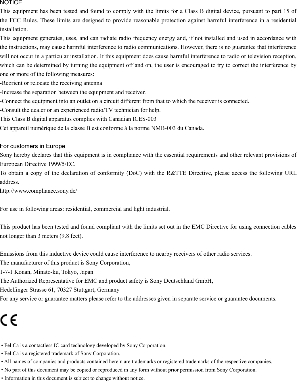
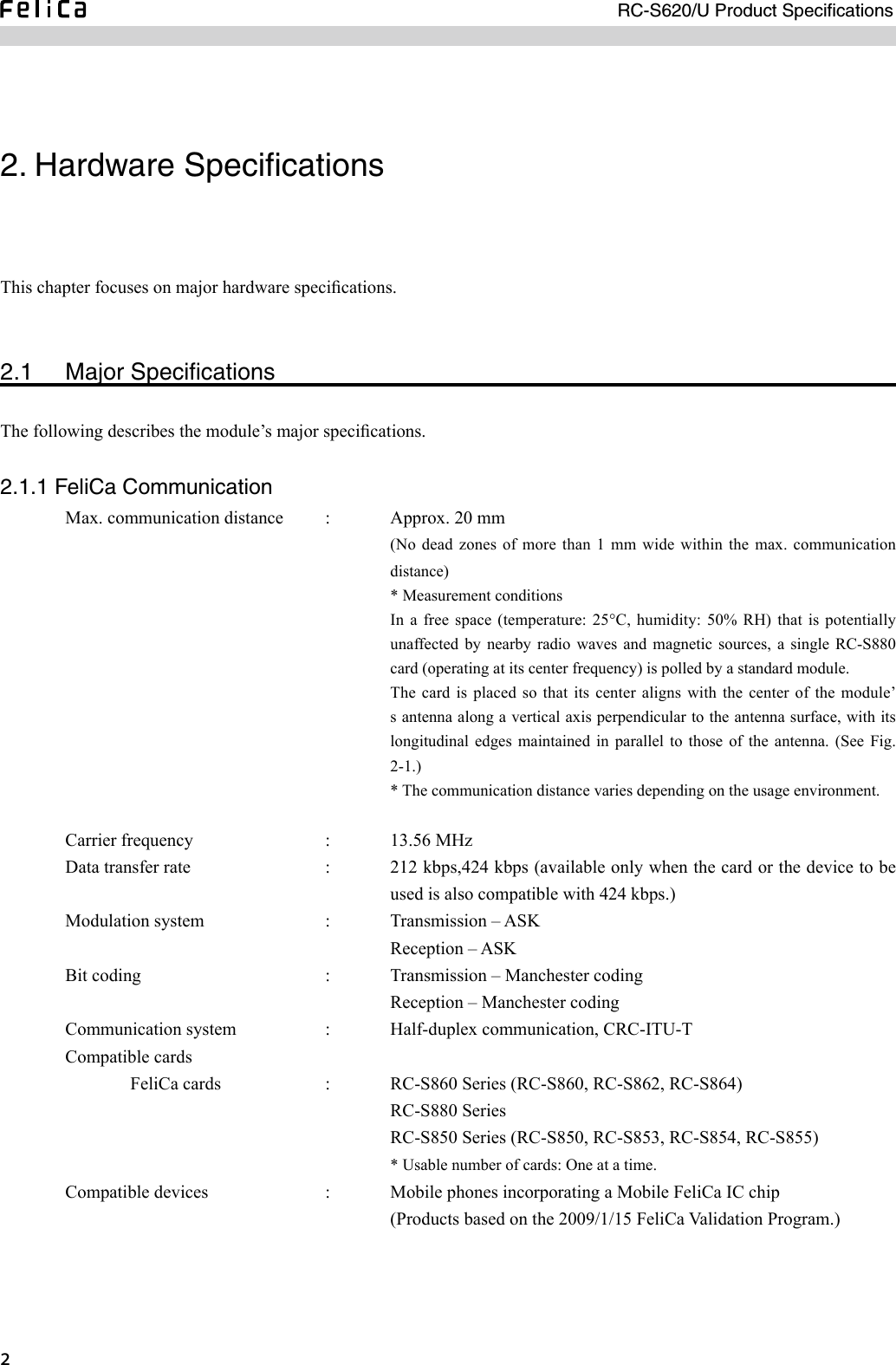
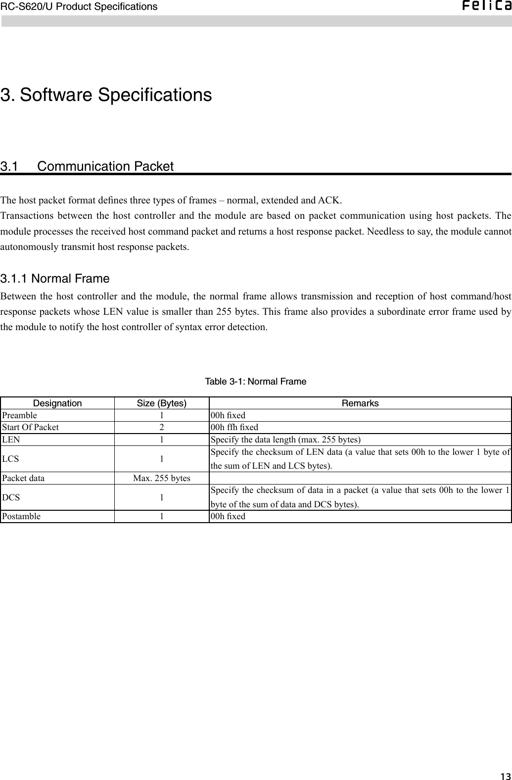
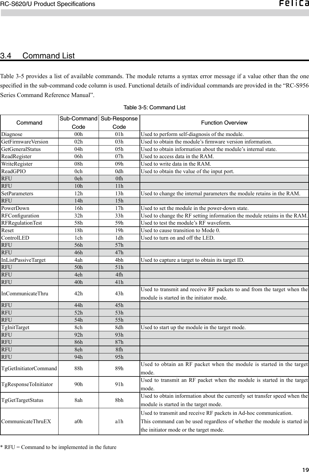
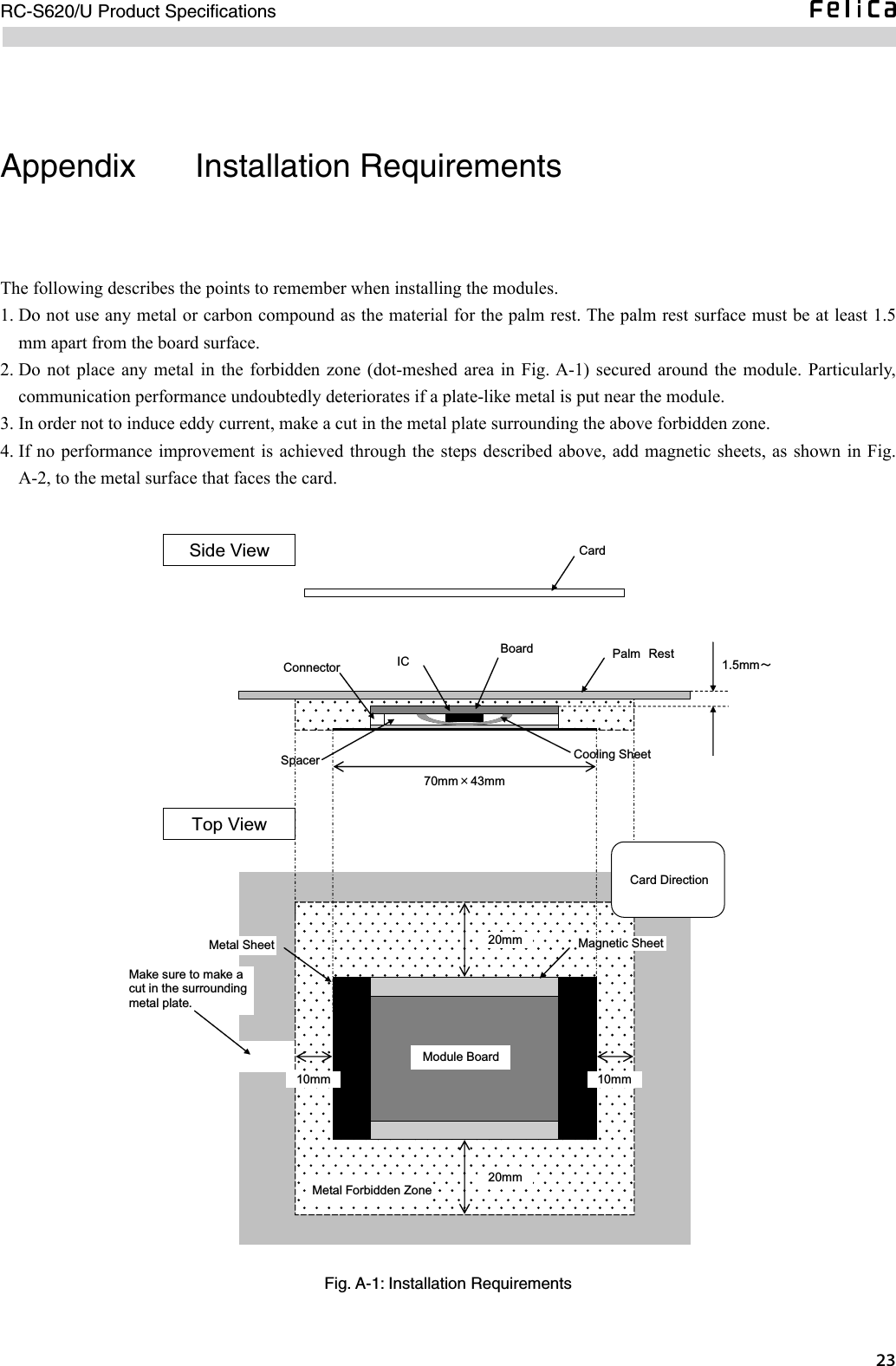
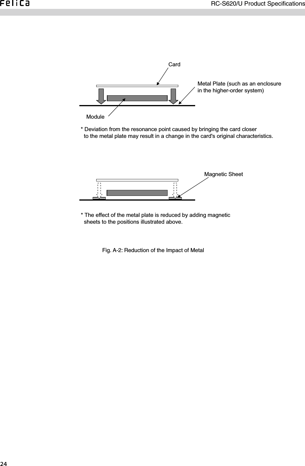
![ RC-S620/U Product Specifications3.2 Communication ProtocolThe communication protocol consists of a data link level and an application level.3.2.1 Data Link LevelThe module uses this level to make sure that the host packet is transmitted or received in accordance with the communication protocol, i.e., without any error. For this purpose, the module veries the following information contained in each host packet.• Host Packet Format - Preamble - Start Of Packet - LEN, LCS - DCS - PostambleIf no error is detected in the received host packet, the module returns an ACK packet to the host controller.A) Fig. 3-1 shows a typical communication sequence on the data link level. ACK Host ControllerResponse TimeHost Command PacketHost Response PacketACK (Optional)ModuleMax. 3.5 [ms]Fig. 3-1: Communication Protocol between Host Controller and Module](https://usermanual.wiki/Sony-Group/RCS620U/User-Guide-1115726-Page-21.png)
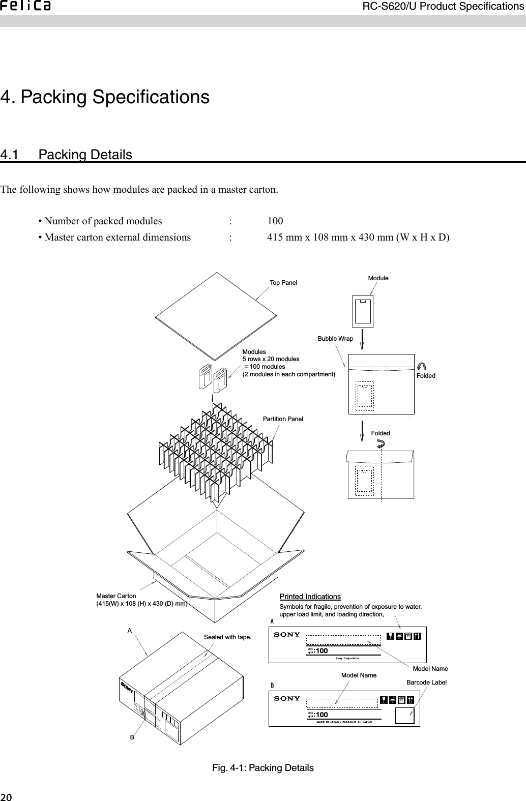
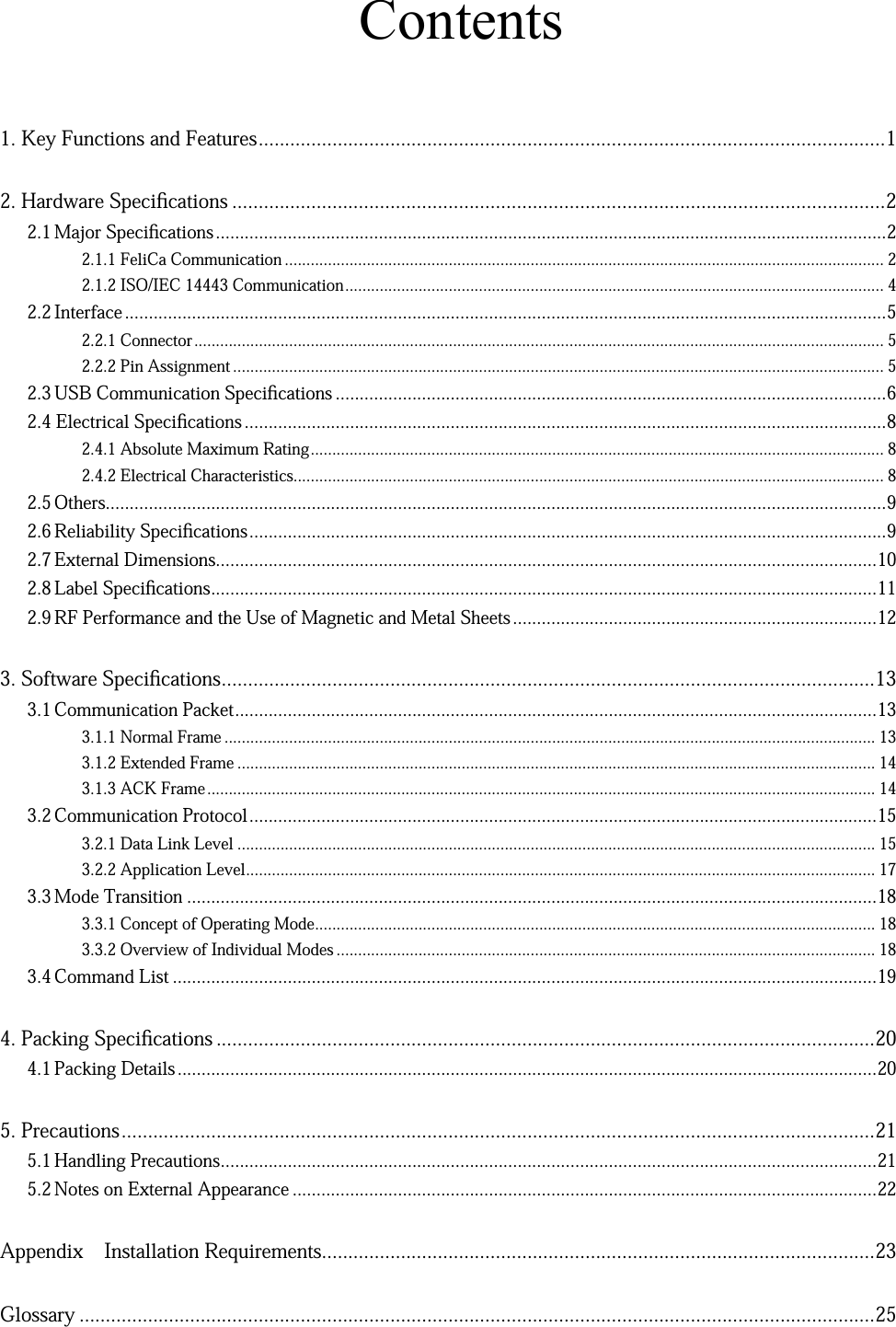
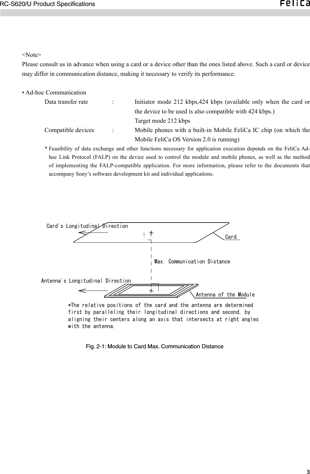
![RC-S620/U Product Specifications3.3 Mode Transition3.3.1 Concept of Operating Mode The module operates in four modes – Mode 0, Mode 1, Mode 5 and Mode 6. Available commands vary according to the mode, while the mode changes as the result of host command execution or RF command reception. For more details, refer to the “RC-S956 Series Command Reference Manual”.3.3.2 Overview of Individual Modes[a] Mode 0[Initial Mode]Used to perform the following functions.• Self diagnosis• Transfer speed setting for host communication• RF waveform test• Various settings for RF communication• Starting up as an initiator or a targetIn Mode 0, the module exists neither as an initiator nor a target. Switching between the initiator and target states cannot be performed without traversing this mode.[b] Mode [Target Initial State]Enables the module to operate as a target to wait for RF command packets.In other words, this is the mode where the TgInitTarget command is executed. Mode 5 is entered as soon as the command execution is normally completed. Reception of a new host command packet terminates and disables the ongoing TgInitTarget command processing and causes transition to Mode 0 for processing of the newly received host command packet.[c] Mode [Target State]The module operates and communicates as a target.[d] Mode [Initiator Operation]The module operates and communicates as an initiator.](https://usermanual.wiki/Sony-Group/RCS620U/User-Guide-1115726-Page-24.png)