Sony Group RCS620U Contactless IC Card Reader/Writer User Manual
Sony Corporation Contactless IC Card Reader/Writer
User Manual

RC-S620 /U
Product Specifications
Reader/Writer Module
Version 1.03
No.M551-E01-03
Introduction
This document describes the major features and specications of Sony’s FeliCa Reader/Writer module, RC-S620/U.
For the purpose of this document, the terms below denote the products or equipment described to the right.
Card : An IC card conforming to Sony's FeliCa contactless IC card technology.
Reader/Writer : A device used to read and write cards based on Sony's FeliCa contactless IC card technology.
Controller : An external computer or an equivalent device that is directly connected to a Reader/Writer via a
specic cable.
User applications use FeliCa libraries to access the RC-S620/U. API specications for these libraries vary depending on
the products used, as well as the intended usage of the system, making it necessary to refer to the appropriate document for
each.
Model Name Description Usage Reference Document
RC-S620/U USB for controller interfacing For Windows PC “SDK for FeliCa User’s Manual”
* “SDK for FeliCa Lite” is also needed to use the RC-S620/U in combination with a Windows PC.
Safety Information and Caution
For customers in USA and Canada
WARNING
You are cautioned that any changes or modications not expressly approved by the party responsible for compliance could
void the user’s authority to operate the equipment.
This device complies with Part 15 of the FCC Rules and RSS-Gen of IC Rules. Operation is subject to the following two
conditions: (1) this device may not cause harmful interference, and (2) this device must accept any interference received,
including interference that may cause undesired operation.

• FeliCa is a contactless IC card technology developed by Sony Corporation.
• FeliCa is a registered trademark of Sony Corporation.
• All names of companies and products contained herein are trademarks or registered trademarks of the respective companies.
• No part of this document may be copied or reproduced in any form without prior permission from Sony Corporation.
• Information in this document is subject to change without notice.
NOTICE
This equipment has been tested and found to comply with the limits for a Class B digital device, pursuant to part 15 of
the FCC Rules. These limits are designed to provide reasonable protection against harmful interference in a residential
installation.
This equipment generates, uses, and can radiate radio frequency energy and, if not installed and used in accordance with
the instructions, may cause harmful interference to radio communications. However, there is no guarantee that interference
will not occur in a particular installation. If this equipment does cause harmful interference to radio or television reception,
which can be determined by turning the equipment off and on, the user is encouraged to try to correct the interference by
one or more of the following measures:
-Reorient or relocate the receiving antenna
-Increase the separation between the equipment and receiver.
-Connect the equipment into an outlet on a circuit different from that to which the receiver is connected.
-Consult the dealer or an experienced radio/TV technician for help.
This Class B digital apparatus complies with Canadian ICES-003
Cet appareil numérique de la classe B est conforme à la norme NMB-003 du Canada.
For customers in Europe
Sony hereby declares that this equipment is in compliance with the essential requirements and other relevant provisions of
European Directive 1999/5/EC.
To obtain a copy of the declaration of conformity (DoC) with the R&TTE Directive, please access the following URL
address.
http://www.compliance.sony.de/
For use in following areas: residential, commercial and light industrial.
This product has been tested and found compliant with the limits set out in the EMC Directive for using connection cables
not longer than 3 meters (9.8 feet).
Emissions from this inductive device could cause interference to nearby receivers of other radio services.
The manufacturer of this product is Sony Corporation,
1-7-1 Konan, Minato-ku, Tokyo, Japan
The Authorized Representative for EMC and product safety is Sony Deutschland GmbH,
Hedelnger Strasse 61, 70327 Stuttgart, Germany
For any service or guarantee matters please refer to the addresses given in separate service or guarantee documents.
Contents
1. Key Functions and Features .......................................................................................................................1
2. Hardware Specications ............................................................................................................................2
2.1 Major Specications ............................................................................................................................................2
2.1.1 FeliCa Communication ........................................................................................................................................... 2
2.1.2 ISO/IEC 14443 Communication ............................................................................................................................. 4
2.2 Interface ...............................................................................................................................................................5
2.2.1 Connector ................................................................................................................................................................ 5
2.2.2 Pin Assignment ....................................................................................................................................................... 5
2.3 USB Communication Specications ...................................................................................................................6
2.4 Electrical Specications ......................................................................................................................................8
2.4.1 Absolute Maximum Rating ..................................................................................................................................... 8
2.4.2 Electrical Characteristics......................................................................................................................................... 8
2.5 Others...................................................................................................................................................................9
2.6 Reliability Specications .....................................................................................................................................9
2.7 External Dimensions..........................................................................................................................................10
2.8 Label Specications ...........................................................................................................................................11
2.9 RF Performance and the Use of Magnetic and Metal Sheets ............................................................................12
3. Software Specications ............................................................................................................................13
3.1 Communication Packet ......................................................................................................................................13
3.1.1 Normal Frame ....................................................................................................................................................... 13
3.1.2 Extended Frame .................................................................................................................................................... 14
3.1.3 ACK Frame ........................................................................................................................................................... 14
3.2 Communication Protocol ...................................................................................................................................15
3.2.1 Data Link Level .................................................................................................................................................... 15
3.2.2 Application Level .................................................................................................................................................. 17
3.3 Mode Transition ................................................................................................................................................18
3.3.1 Concept of Operating Mode .................................................................................................................................. 18
3.3.2 Overview of Individual Modes ............................................................................................................................. 18
3.4 Command List ...................................................................................................................................................19
4. Packing Specications .............................................................................................................................20
4.1 Packing Details ..................................................................................................................................................20
5. Precautions ...............................................................................................................................................21
5.1 Handling Precautions .........................................................................................................................................21
5.2 Notes on External Appearance ..........................................................................................................................22
Appendix Installation Requirements .........................................................................................................23
Glossary .......................................................................................................................................................25

RC-S620/U Product Specifications
1. Key Functions and Features
The RC-S620/U (hereinafter called the module) writes and reads data to and from FeliCa-enabled contactless IC cards. It
can also write and read data based on the ISO/IEC 14443 communication standards. Immune to wear caused by dirt and
friction, contactless operation leads to enhanced maintainability. Key functions and features of the module are detailed
below.
• Based on an inductive read/write system type-certied by the Radio Law of Japan.
• Environmentally friendly, with the adoption of lead-free soldering.
• Compatible with devices such as mobile phones incorporating a Mobile FeliCa IC chip.
* Not all of the processing sequences can be handled.
• Compactly designed with an integral antenna.
• Requires the use of specied magnetic and metal sheets.
• Interface versatility made possible by the use of USB for host controller connection.
• Successful passage of rigorous validation tests by Microsoft’s WHQL (Windows Hardware Quality Labs).

RC-S620/U Product Specifications
2. Hardware Specifications
This chapter focuses on major hardware specications.
2.1 Major Specifications
The following describes the module’s major specications.
2.1.1 FeliCa Communication
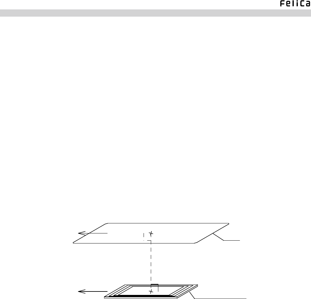
Max. communication distance : Approx. 20 mm
(No dead zones of more than 1 mm wide within the max. communication
distance)
* Measurement conditions
In a free space (temperature: 25°C, humidity: 50% RH) that is potentially
unaffected by nearby radio waves and magnetic sources, a single RC-S880
card (operating at its center frequency) is polled by a standard module.
The card is placed so that its center aligns with the center of the module’
s antenna along a vertical axis perpendicular to the antenna surface, with its
longitudinal edges maintained in parallel to those of the antenna. (See Fig.
2-1.)
* The communication distance varies depending on the usage environment.
Carrier frequency : 13.56 MHz
Data transfer rate : 212 kbps,424 kbps (available only when the card or the device to be
used is also compatible with 424 kbps.)
Modulation system : Transmission – ASK
Reception – ASK
Bit coding : Transmission – Manchester coding
Reception – Manchester coding
Communication system : Half-duplex communication, CRC-ITU-T
Compatible cards
FeliCa cards : RC-S860 Series (RC-S860, RC-S862, RC-S864)
RC-S880 Series
RC-S850 Series (RC-S850, RC-S853, RC-S854, RC-S855)
* Usable number of cards: One at a time.
Compatible devices : Mobile phones incorporating a Mobile FeliCa IC chip
(Products based on the 2009/1/15 FeliCa Validation Program.)
RC-S620/U Product Specifications
Fig. 2-1: Module to Card Max. Communication Distance
<Note>
Please consult us in advance when using a card or a device other than the ones listed above. Such a card or device
may differ in communication distance, making it necessary to verify its performance.
• Ad-hoc Communication
Data transfer rate : Initiator mode 212 kbps,424 kbps (available only when the card or
the device to be used is also compatible with 424 kbps.)
Target mode 212 kbps
Compatible devices : Mobile phones with a built-in Mobile FeliCa IC chip (on which the
Mobile FeliCa OS Version 2.0 is running)
* Feasibility of data exchange and other functions necessary for application execution depends on the FeliCa Ad-
hoc Link Protocol (FALP) on the device used to control the module and mobile phones, as well as the method
of implementing the FALP-compatible application. For more information, please refer to the documents that
accompany Sony’s software development kit and individual applications.
Antenna's Longitudinal Direction
Card's Longitudinal Direction
Max. Communication Distance
Card
Antenna of the Module
*The relative positions of the card and the antenna are determined
first by paralleling their longitudinal directions and second, by
aligning their centers along an axis that intersects at right angles
with the antenna.

RC-S620/U Product Specifications
2.1.2 ISO/IEC 14443 Communication
Carrier frequency : 13.56 MHz
Data transfer rate : 106 kbps
Modulation system
Type A : Transmission – ASK
Reception – ASK
Type B : Transmission – ASK
Reception – BPSK
Bit coding
Type A : Transmission – Modied mirror
Reception – Manchester coding with subcarrier
Type B : Transmission – NRZ
Reception – NRZ with subcarrier
Communication system : Half-duplex communication
Compatible cards : Mifare Standard, Mifare UltraLight, Mifare DESFire,
Innovision Jewel, Calypso CDLight
* Compliant with ISO/IEC 14443 Type A, Mifare and ISO/IEC 14443 Type B
standards.
RC-S620/U Product Specifications
2.2 Interface
Interfacing between the module and the controller utilizes the connector described below.
2.2.1 Connector
Model number: 08 6223 006 101 868+ (Au Plated) made by Kyocera Elco Corporation
Low-prole, 0.5 mm pitch FFC/FPC connector (SMT/right angle/NON-ZIF/6 poles)
* Refer to “Section 2-7: External Dimensions” for the contact point direction.
* Consult the manufacturer for detailed specications.
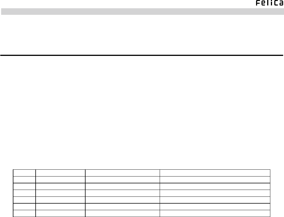
2.2.2 Pin Assignment
Table 2-1: Pin Assignment
Pin No. Designation Function Remarks
1 VDD Power supply connector DC3.3V input
2 D – (USB) USB D – signal USB2.0 (Full Speed)
3 D + (USB) USB D + signal USB2.0 (Full Speed)
4 GND Ground connector For grounding
5 Reserve Non Requires OPEN processing by the controller
6 PRS(GND) Module identication signal Fixed at “L” (with GND grounded)
RC-S620/U Product Specifications
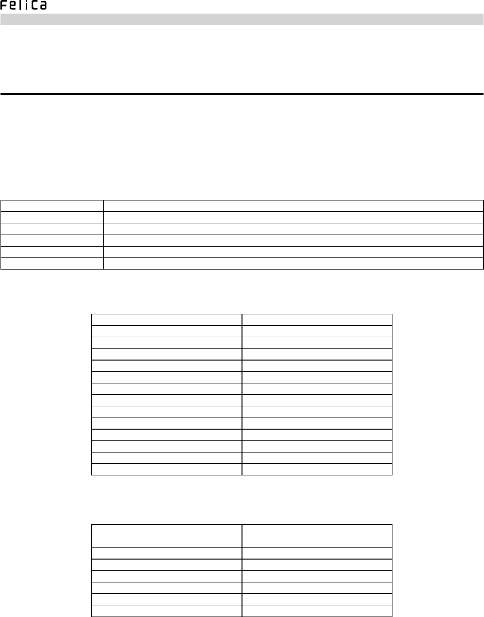
2.3 USB Communication Specifications
A suspend signal from the controller is received through the USB interface to offer the capability for reduced power
consumption.
See the tables below for USB communication specications.
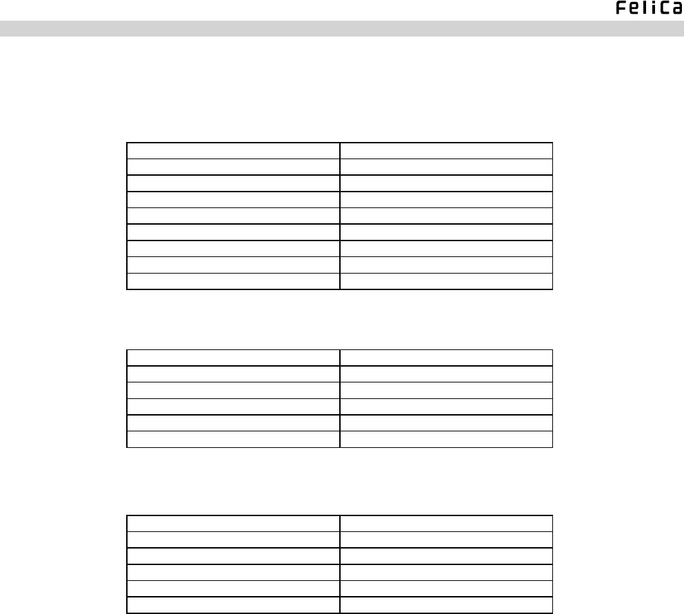
Table 2-2: Communication Specifications
USB transfer speed USB 2.0 compliant, Full Speed
No. of endpoints 2
Endpoint 0 Control transfer using individual 8-byte buffers for IN and OUT directions
Endpoint 4 Bulk transfer using individual 64-byte buffers for IN and OUT directions
Command transfer Data of any given packet length is bulk-transferred to Endpoint 4 (OUT direction).
Response transfer Data of any given packet length is bulk-transferred from Endpoint 4 (IN direction).
Table 2-3: Device Descriptor
bLength 12h
bDescriptorType 01h
bcdUSB 0200h
bDeviceClass 00h
bDeviceSubClass 00h
bDeviceProtocol 00h
bMaxPacketSize0 08h
idVendor 054ch
idProduct 02e1h
bcdDevice 0130h
iManufacturer 01h
iProduct 00h
iSerialNumber 00h
bNumCongurations 01h
Table 2-4: Configuration Descriptor
bLength 09h
bDescriptorType 02h
wTotalLength 0020h
bNumInterfaces 01h
bCongurationValue 01h
iConguration 00h
bmAttributes 80h
MaxPower 32h
RC-S620/U Product Specifications
Table 2-5: Interface Descriptor
bLength 09h
bDescriptorType 04h
bInterfaceNumber 00h
bAlternateSetting 00h
bNumEndpoints 02h
bInterfaceClass ffh
bInterfaceSubClass ffh
bInterfaceProtocol ffh
iInterface 00h
Table 2-6: Endpoint Descriptor (OUT)
bLength 07h
bDescriptorType 05h
bEndpointAddress 04h
bmAttributes 02h
wMaxPacketSize 0040h
bInterval 00h
Table 2-7: Endpoint Descriptor (IN)
bLength 07h
bDescriptorType 05h
bEndpointAddress 84h
bmAttributes 02h
wMaxPacketSize 0040h
bInterval 00h
RC-S620/U Product Specifications
*1 To power the module, use the USB-controlled Vbus power voltage after stepping it down by using a regulator or something
similar.
*2 The module’s max. current consumption is the same as the value set to MaxPower of the USB descriptor
2.4 Electrical Specifications
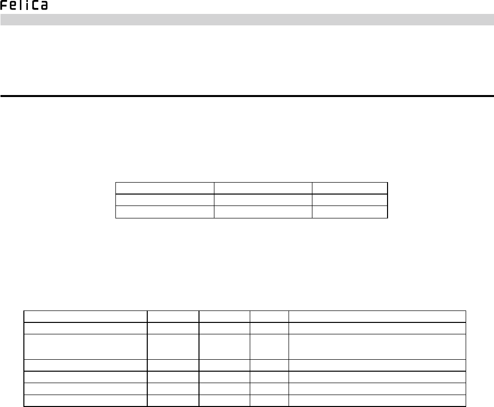
2.4.1 Absolute Maximum Rating
Observe the following ranges of operation in order to avoid irreparable damage to the module.
Item Rating Unit
Power supply voltage +3.9 V
Input voltage +3.9 V
Table 2-8: Absolute Maximum Rating
2.4.2 Electrical Characteristics
Table 2-9: Electrical Characteristics
(Conditions) Temperature: 25°C, Humidity: 50% RH
Item Min Max Unit Remarks
Power supply voltage (VDD)*1 3.15 3.45 V DC 3.3V input
Current consumption (IVDD) *2 —100 mA RF ON: Approx. 70 mA
RF OFF: Approx. 20 mA
H-level output voltage 2.8 VDD V Lower than the power supply voltage (VDD)
L-level output voltage 0 0.3 V
H-level input voltage 2.0 3.6 V VDD = 3.3 V
L-level input voltage 0 0.8 V
RC-S620/U Product Specifications
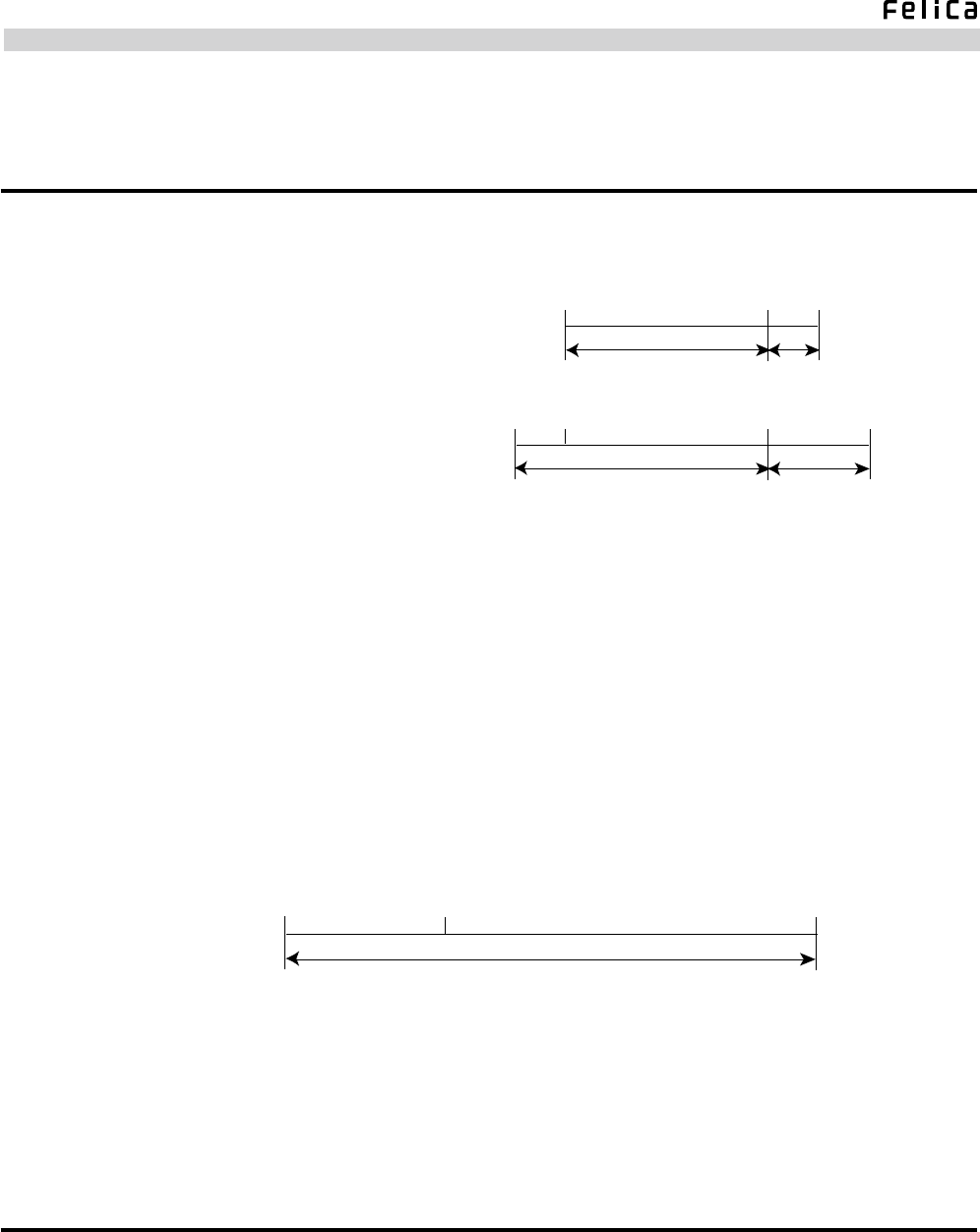
2.5 Others
• Operating environment (no condensation or frost)
• Storage environment (no condensation or frost)
0℃40℃50℃
20%~90%RH Less than 50% RH
Performance Assurance Temperature/Humidity
0℃40℃60℃
20%~90%RH Less than 50% RH
-10℃
Function Assurance Temperature/Humidity
* Performance Assurance Temperature/Humidity :
Guarantees more than 80% of the max. communication distance (25℃, 50%RH) defined in
"Section 2.1.1: FeliCa Communication".
Function Assurance Temperature/Humidity:
Guarantees normal operation of the RF communication processor, although the
communication performance described above cannot be assured in temperature extremes.
* The board temperature inevitably rises if the Reader/Writer is continually transmitting card
access commands (such as when polling a card). Make sure to design the enclosure so
that the internal temperature and humidity can be held within the specified ranges.
• Mass : Approx. 17 g
0℃70℃
Less than 60% RH
-30℃
2.6 Reliability Specifications
• Shock : IEC60068-2-27 Part2 Test Ea
• Vibration : IEC60068-2-6 Part2 Test EC
RC-S620/U Product Specifications
0
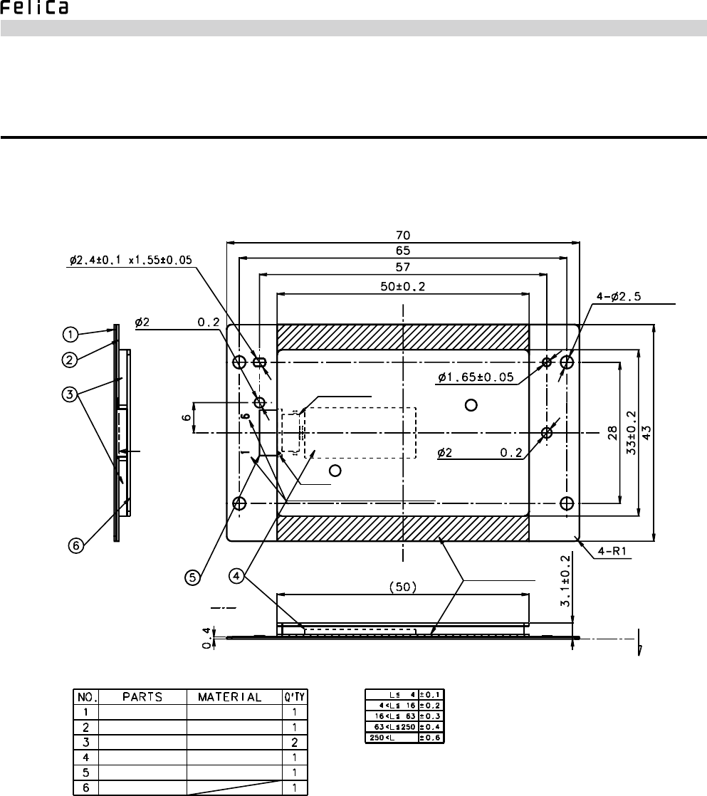
2.7 External Dimensions
External dimensions of the module are illustrated below.
Fig. 2-2: External Dimensions
(Hole)
(Hole)
Convex:
Convex:
Pin 1
Pin 1
Connector Contact Surface: Indicated by
6-Pin Connector
NON-ZIF
Pin Assignment Number (Engraved)
Magnetic Sheet
Trimming Burr Direction
Magnetic sheet
Metal sheet
Spacer
Cooling sheet
Insulating tape
Board
Soft magnetic sheet
SPTE
Polyurethane foam
Silicon sheet
Polyester tape (Unit: mm)
RC-S620/U Product Specifications
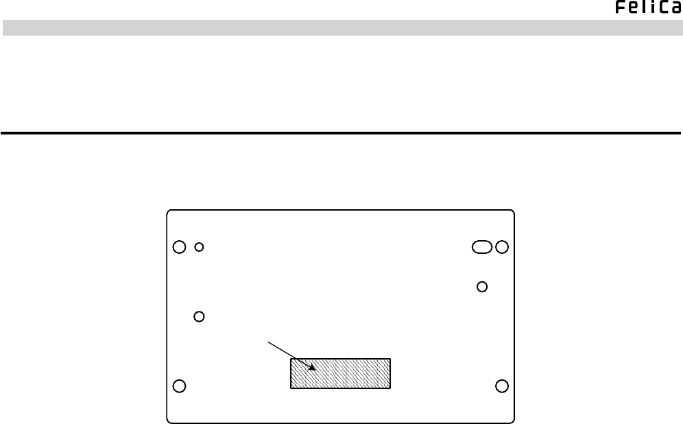
2.8 Label Specifications
The module bears a serial label in the position shown below.
Serial Label
Fig. 2-3: Position of Labels (Metal Sheet)

RC-S620/U Product Specifications
2.9 RF Performance and the Use of Magnetic and Metal Sheets
• RF (communication) performance is closely related to the effectiveness of the magnetic and metal sheets used below and
around the antenna of the module.
• RF performance varies considerably, depending not only on the magnetic permeability (μ’, μ”), dimensions and thickness
of the magnetic sheet but also on the dimensions and material of the metal sheet used. There is also a possibility that it is
affected by metal in the installation environment.
• The module is designed to be used with the specified magnetic and metal sheets attached in advance to control the
magnetic eld generated by the antenna, as well as to minimize the possible effects from the installation environment.
This contributes a great deal to the reduction of the time required for weighing the effects of the installation environment
and evaluating the module’s RF performance.
RC-S620/U Product Specifications
3. Software Specifications
3.1 Communication Packet
The host packet format denes three types of frames – normal, extended and ACK.
Transactions between the host controller and the module are based on packet communication using host packets. The
module processes the received host command packet and returns a host response packet. Needless to say, the module cannot
autonomously transmit host response packets.
3.1.1 Normal Frame
Between the host controller and the module, the normal frame allows transmission and reception of host command/host
response packets whose LEN value is smaller than 255 bytes. This frame also provides a subordinate error frame used by
the module to notify the host controller of syntax error detection.
Table 3-1: Normal Frame
Designation Size (Bytes) Remarks
Preamble 1 00h xed
Start Of Packet 2 00h ffh xed
LEN 1 Specify the data length (max. 255 bytes)
LCS 1 Specify the checksum of LEN data (a value that sets 00h to the lower 1 byte of
the sum of LEN and LCS bytes).
Packet data Max. 255 bytes
DCS 1 Specify the checksum of data in a packet (a value that sets 00h to the lower 1
byte of the sum of data and DCS bytes).
Postamble 1 00h xed
RC-S620/U Product Specifications
3.1.2 Extended Frame
The extended frame is used to send and receive host command/host response packets whose LEN value is greater than 256
bytes and smaller than 265 bytes.
Table 3-2: Extended Frame
Designation Size (Bytes) Remarks
Preamble 1 00h xed
Start Of Packet 2 00h ffh xed
2-byte frame identication code 2 ffh ffh xed
LEN 2 Specify the data length (max. 265 bytes) in the big endian format. All data
greater than 266 bytes is interpreted as 265 bytes.
LCS 1 Specify the checksum of LEN data (a value that sets 00h to the lower 1 byte of
the sum of 2-byte LEN and 1-byte LCS).
Packet data Max. 265 bytes
DCS 1 Specify the checksum of data in a packet (a value that sets 00h to the lower 1
byte of the sum of data and DCS bytes).
Postamble 1 00h xed
Which type of frame is to be used for the host response packet is automatically determined – the normal frame if the LEN
value is below 255 bytes and the extended frame if it is over 256 bytes.
3.1.3 ACK Frame
The ACK frame is intended for use in the following situations.
• Module to Host Controller Transmission
- Informing the host controller that no data link level error is detected in the received host command packet.
* This is the one and only instance the module transmits the ACK frame.
• Host Controller to Module Transmission
- Interrupting host command execution.
- Determining the results on command execution (prerequisite with the Reset command). For more information, refer to
the “RC-S956 Series Command Reference Manual”.
* In the cases other than those above, the module ignores the ACK frame received from the host controller.
Table 3-3: ACK Frame
Designation Size (Bytes) Remarks
Preamble 1 00h xed
Start Of Packet 2 00h ffh xed
LEN 1 00h xed
LCS 1 ffh xed
Postamble 1 00h xed
RC-S620/U Product Specifications
3.2 Communication Protocol
The communication protocol consists of a data link level and an application level.
3.2.1 Data Link Level
The module uses this level to make sure that the host packet is transmitted or received in accordance with the
communication protocol, i.e., without any error. For this purpose, the module veries the following information contained
in each host packet.
• Host Packet Format
- Preamble
- Start Of Packet
- LEN, LCS
- DCS
- Postamble
If no error is detected in the received host packet, the module returns an ACK packet to the host controller.
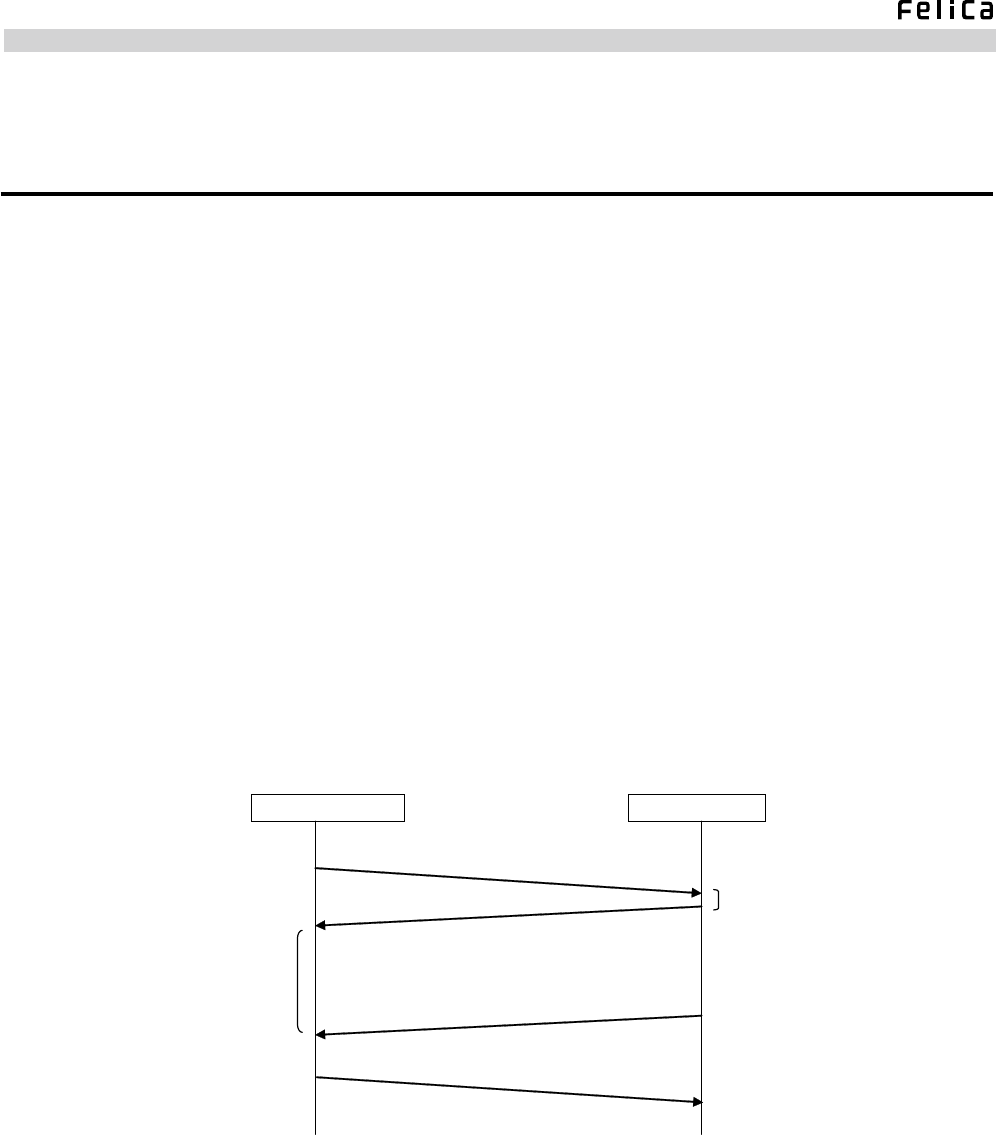
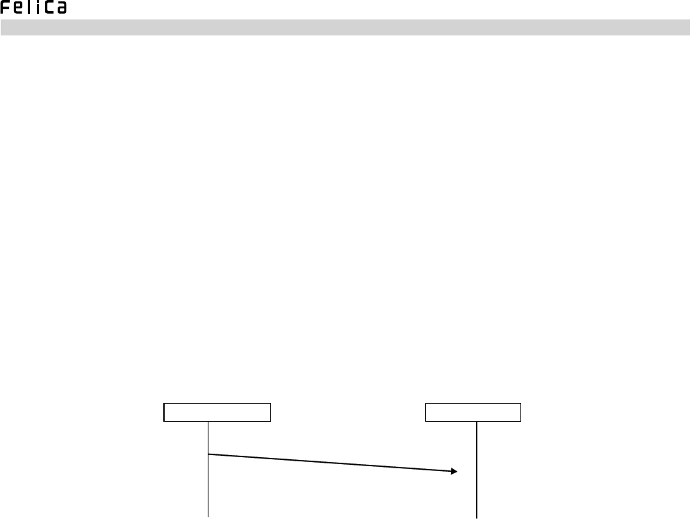
A) Fig. 3-1 shows a typical communication sequence on the data link level.
ACK
Host Controller
Response Time
Host Command Packet
Host Response Packet
ACK (Optional)
Module
Max. 3.5 [ms]
Fig. 3-1: Communication Protocol between Host Controller and Module
RC-S620/U Product Specifications
If the host command packet is veried, the module prepares an ACK frame within 3.5 ms. Stated the other way round, the
module requires a maximum of 3.5 ms in order to be ready to transmit an ACK packet after receiving an IN packet.
Acknowledging packet reception, the module proceeds to host command processing, returns a host response packet, and
waits for the reception of the next host command packet. Accordingly, it is not necessary for the host controller to be
concerned with the time interval between the reception of a host response packet and the transmission of the next host
command packet. Upon detection of a host response packet from the module, the controller optionally transmits an ACK
frame to the module.
B) If a data link level error is detected, the module remains non-responsive to the host controller. Seeing that no ACK frame
is returned, the host controller retransmits a host command packet to recover communication.
Fig. 3-2: Data Link Level Error in Host Command Packet
X
Host Controller Module
Host Command Packet
Major errors encountered during data link level communication are listed below.
1. Start of Packet Error
The second byte of the host command packet is not 00h, or the third byte is not ffh.
2. LCS Error
The lower 1 byte of the sum of LEN and LCS is not 00h.
3. DCS Error
The lower 1 byte of the sum obtained by adding up all data bytes and DCS is not 00h.
4. Postamble Error
The postamble byte is not included.
RC-S620/U Product Specifications
3.2.2 Application Level
This is the level where the module executes the host command specied in the host command packet.
A) When command processing is complete, the module returns a host response packet to the controller.
B) The host controller transmits an ACK frame when it is necessary to interrupt command execution by the module. The
next host command cannot be sent until more than 1 ms elapses from the interruption of host command execution (or the
completion of ACK frame transmission).
• In addition to when an ACK frame is received, the module discontinues host command processing if one of the
following factors is detected. Thereafter, it reacts by performing necessary processing, depending on the detected
factor.
- Reception of a standard USB request (Necessary processing: Responding to the request)
- USB RESET
- USB IDLE of more than 3 ms duration (Necessary processing: Suspending USB communication)
- Reception of a packet bulk-transferred (OUT direction) from Endpoint 4
C) If a syntax error is detected in the received packet, the module noties the controller by returning an error frame.
Table 3-4: Error Frame
Designation Size (Bytes) Remarks
Preamble 1 00h xed
Start Of Packet 2 00h ffh xed
LEN 1 01h xed
LCS 1 ffh xed
Packet data 1 7fh xed
DCS 1 81h xed
Postamble 1 00h xed

RC-S620/U Product Specifications
3.3 Mode Transition
3.3.1 Concept of Operating Mode
The module operates in four modes – Mode 0, Mode 1, Mode 5 and Mode 6. Available commands vary according to the
mode, while the mode changes as the result of host command execution or RF command reception. For more details, refer
to the “RC-S956 Series Command Reference Manual”.
3.3.2 Overview of Individual Modes
[a] Mode 0
[Initial Mode]
Used to perform the following functions.
• Self diagnosis
• Transfer speed setting for host communication
• RF waveform test
• Various settings for RF communication
• Starting up as an initiator or a target
In Mode 0, the module exists neither as an initiator nor a target. Switching between the initiator and target states cannot be
performed without traversing this mode.
[b] Mode
[Target Initial State]
Enables the module to operate as a target to wait for RF command packets.
In other words, this is the mode where the TgInitTarget command is executed. Mode 5 is entered as soon as the command
execution is normally completed. Reception of a new host command packet terminates and disables the ongoing
TgInitTarget command processing and causes transition to Mode 0 for processing of the newly received host command
packet.
[c] Mode
[Target State]
The module operates and communicates as a target.
[d] Mode
[Initiator Operation]
The module operates and communicates as an initiator.

RC-S620/U Product Specifications
3.4 Command List
Table 3-5 provides a list of available commands. The module returns a syntax error message if a value other than the one
specied in the sub-command code column is used. Functional details of individual commands are provided in the “RC-S956
Series Command Reference Manual”.
Table 3-5: Command List
Command Sub-Command
Code
Sub-Response
Code Function Overview
Diagnose 00h 01h Used to perform self-diagnosis of the module.
GetFirmwareVersion 02h 03h Used to obtain the module’s rmware version information.
GetGeneralStatus 04h 05h Used to obtain information about the module’s internal state.
ReadRegister 06h 07h Used to access data in the RAM.
WriteRegister 08h 09h Used to write data in the RAM.
ReadGPIO 0ch 0dh Used to obtain the value of the input port.
RFU 0eh 0fh
RFU 10h 11h
SetParameters 12h 13h Used to change the internal parameters the module retains in the RAM.
RFU 14h 15h
PowerDown 16h 17h Used to set the module in the power-down state.
RFConguration 32h 33h Used to change the RF setting information the module retains in the RAM.
RFRegulationTest 58h 59h Used to test the module’s RF waveform.
Reset 18h 19h Used to cause transition to Mode 0.
ControlLED 1ch 1dh Used to turn on and off the LED.
RFU 56h 57h
RFU 46h 47h
InListPassiveTarget 4ah 4bh Used to capture a target to obtain its target ID.
RFU 50h 51h
RFU 4eh 4fh
RFU 40h 41h
InCommunicateThru 42h 43h Used to transmit and receive RF packets to and from the target when the
module is started in the initiator mode.
RFU 44h 45h
RFU 52h 53h
RFU 54h 55h
TgInitTarget 8ch 8dh Used to start up the module in the target mode.
RFU 92h 93h
RFU 86h 87h
RFU 8eh 8fh
RFU 94h 95h
TgGetInitiatorCommand 88h 89h Used to obtain an RF packet when the module is started in the target
mode.
TgResponseToInitiator 90h 91h Used to transmit an RF packet when the module is started in the target
mode.
TgGetTargetStatus 8ah 8bh Used to obtain information about the currently set transfer speed when the
module is started in the target mode.
CommunicateThruEX a0h a1h
Used to transmit and receive RF packets in Ad-hoc communication.
This command can be used regardless of whether the module is started in
the initiator mode or the target mode.
* RFU = Command to be implemented in the future
RC-S620/U Product Specifications
0
4. Packing Specifications
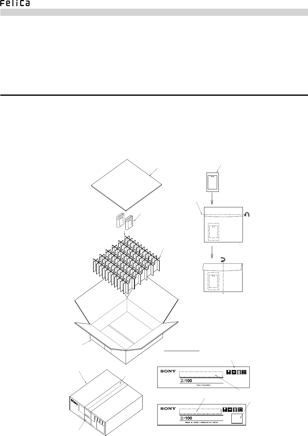
4.1 Packing Details
The following shows how modules are packed in a master carton.
• Number of packed modules : 100
• Master carton external dimensions : 415 mm x 108 mm x 430 mm (W x H x D)
Fig. 4-1: Packing Details
A
B
A
B
100
Qty.
q'te.
Top Panel
Modules
5 rows x 20 modules
= 100 modules
(2 modules in each compartment)
Partition Panel
Master Carton
(415(W) x 108 (H) x 430 (D) mm)
Sealed with tape.
Module
Bubble Wrap
Folded
Folded
Printed Indications
Symbols for fragile, prevention of exposure to water,
upper load limit, and loading direction,
Model Name
Model Name
Barcode Label

RC-S620/U Product Specifications
5. Precautions
5.1 Handling Precautions
The module must be handled with special care, keeping the following precautions in mind.
• This module is an inductive-type read/write communication device that is type-certied in compliance with the Radio Law
of Japan. The operating frequency is 13.56 MHz. Disassembly or modication of the module, removal of the type number
or similar acts are subject to penalties according to applicable laws.
• Be sure to use a stable power supply so that the module can be protected from the effect of noise and excessive voltage
peaks, such as lightning, transmitted through the power supply connector.
• Do not cause any chemical or physical damage to the module.
• Do not subject the module surface to contaminated air or materials.
• Ground all jigs, machines, workbenches and workers’ bodies to prevent static electricity from affecting the module.
• For safety’s sake, be sure to wear gloves when handling the module, although its surfaces are carefully nished.
• Protect the module from interference from other wireless machines.
• Do not install the module in an environment where a strong electromagnetic field may exert deleterious effects on
communication performance. Take special note of the installation location so that interference between the module and
other equipment can be adequately controlled.
• Communication performance may be affected by the harmonics of the 13.56 MHz carrier frequency generated on the
signal line.
• Check in advance the compatibility between the module and your system. The module cannot handle part of the
processing sequences* provided by mobile phones and other portable devices incorporating mobile FeliCa IC chips.
• The interface cable (FFC/FPC) is not supplied, making it necessary to prepare the one appropriate for your system. When
selecting the cable, make sure of the contact point direction because the module uses a single-sided interface connector.
• Measures for static noise and power line noise must be designed and incorporated on your own.
* Among the processing sequences unique to mobile FeliCa compatible portable devices, the module cannot handle the sequence which
allows wireless communication from the Reader/Writer after the mobile FeliCa IC chip was activated by the portable device via a
wired interface. For more information, refer to the “Mobile FeliCa Technical Information” (Japanese only) that explains Reader/Writer
operation in mobile applications.

RC-S620/U Product Specifications
5.2 Notes on External Appearance
Since the module is designed for embedded applications, please realize that aws on the order described below may occur.
• Scratch or stain on the product surface, which has no effect on performance.
• Change in the board color.
RC-S620/U Product Specifications
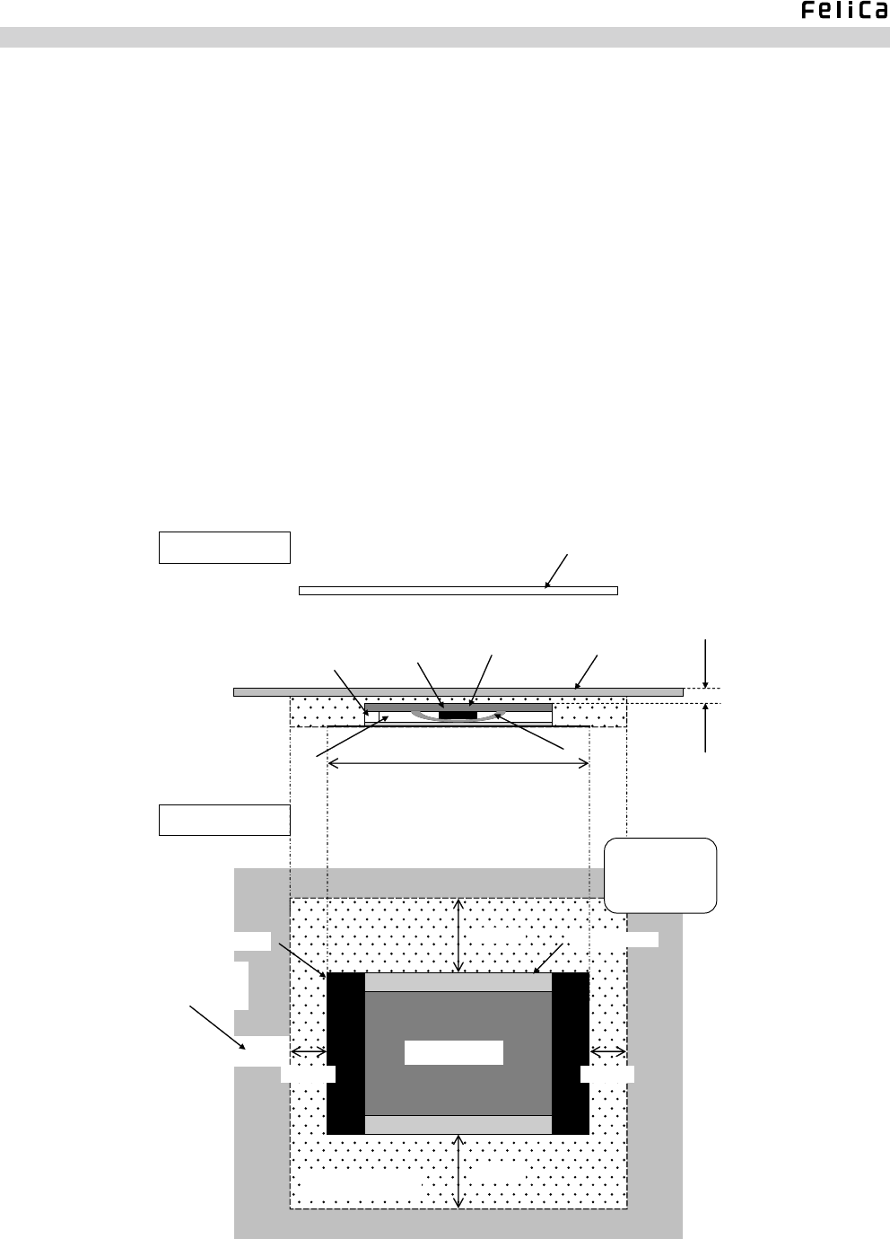
Appendix Installation Requirements
The following describes the points to remember when installing the modules.
1. Do not use any metal or carbon compound as the material for the palm rest. The palm rest surface must be at least 1.5
mm apart from the board surface.
2. Do not place any metal in the forbidden zone (dot-meshed area in Fig. A-1) secured around the module. Particularly,
communication performance undoubtedly deteriorates if a plate-like metal is put near the module.
3. In order not to induce eddy current, make a cut in the metal plate surrounding the above forbidden zone.
4. If no performance improvement is achieved through the steps described above, add magnetic sheets, as shown in Fig.
A-2, to the metal surface that faces the card.
Side View
70mm×43mm
Top View
20mm
20mm
10mm 10mm
Palm Rest
IC 1.5mm~
Card
Connector
Board
Cooling Sheet
Metal Sheet Magnetic Sheet
Card Direction
Module Board
Metal Forbidden Zone
Spacer
Make sure to make a
cut in the surrounding
metal plate.
Fig. A-1: Installation Requirements
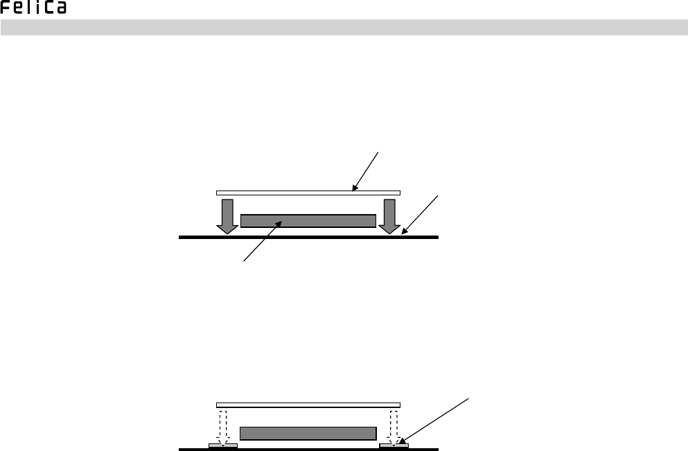
RC-S620/U Product Specifications
Card
Module
Magnetic Sheet
Metal Plate (such as an enclosure
in the higher-order system)
* Deviation from the resonance point caused by bringing the card closer
to the metal plate may result in a change in the card's original characteristics.
* The effect of the metal plate is reduced by adding magnetic
sheets to the positions illustrated above.
Fig. A-2: Reduction of the Impact of Metal

RC-S620/U Product Specifications
Glossary
(In alphabetical Order)
ACK
Abbreviation for ACKnowledgement, which means an afrmative message transmitted when, for example, data transfer is
successfully completed.
ASK
ASK stands for Amplitude Shift Keying. The amplitude of the carrier frequency is modulated according to the logic of the
data to be transmitted.
The degree of modulation (normally indicated in percent) is expressed by (a - b)/(a + b), where a and b respectively
represent the maximum and minimum amplitudes of the modulated signal waveform.
DCS
Abbreviation for packet Data CheckSum representing the checksum for packet data.
Initiator
A device that initiates RF communication transactions by issuing the first RF command packet. Equivalent to the
conventional FeliCa Reader/Writer.
LCS
Abbreviation for packet Length CheckSum representing the checksum for all data bytes specied by the LEN byte.
LEN
Abbreviation for packet LENgth, indicating the number of data bytes contained in the packet.
Manchester Encoding
A method of coding bit data. The bit duration time is divided at the transition point in the center and translated into two
logical values.
Target
A device that returns an RF response packet to the RF command received from the initiator in RF communications.
Equivalent to the conventional card. During Ad-hoc transactions (possible with the use of devices operating on the Mobile
FeliCa OS Version 2.0), there is a case where the target sends a command to the initiator.

RC-S620/U Product Specifications
(Blank Page)

Reader/Writer Module
RC-S620/U Product Specifications Version 1.03
February, 2009 First edition issued FeliCa Business Division
April ,2009 Revised
Sony Corporation
No.M551-E01-03
©2009 Sony Corporation Printed in Japan