Sony Group RMTP100 Low Power Communication Device Transmitter User Manual CAV M1000ES
Sony Corporation Low Power Communication Device Transmitter CAV M1000ES
User Manual

4-253-728-11(1)
Custom Integrated
AV System
2004 Sony Corporation
CAV-M1000ES
Installation Manual
Owner’s Record
The model and serial numbers are located on the rear panel. Record the model
and serial numbers in the spaces provided below. Refer to them whenever you
call upon your Sony dealer regarding this product.
Model No. Serial No.
2
WARNING
To prevent fire or shock
hazard, do not expose the
unit to rain or moisture.
To avoid electrical shock,
do not open the cabinet.
Refer servicing to qualified
personnel only.
This symbol is intended to alert the
user to the presence of uninsulated
“dangerous voltage” within the
product’s enclosure that may be of
sufficient magnitude to constitute a
risk of electric shock to persons.
This symbol is intended to alert the
user to the presence of important
operating and maintenance
(servicing) instructions in the
literature accompanying the
appliance.
WARNING
This equipment has been tested and found
to comply with the limits for a Class B
digital device, pursuant to Part 15 of the
FCC Rules. These limits are designed to
provide reasonable protection against
harmful interference in a residential
installation. This equipment generates,
uses, and can radiate radio frequency
energy and, if not installed and used in
accordance with the instructions, may
cause harmful interference to radio
communications. However, there is no
guarantee that interference will not occur
in a particular installation. If this
equipment does cause harmful interference
to radio or television reception, which can
be determined by turning the equipment
off and on, the user is encouraged to try to
correct the interference by one or more of
the following measures:
– Reorient or relocate the receiving
antenna.
– Increase the separation between the
equipment and receiver.
– Connect the equipment to an outlet on a
circuit different from that to which the
receiver is connected.
– Consult the dealer or an experienced
radio/TV technician for help.
CAUTION
You are cautioned that any changes or
modification not expressly approved in this
manual could void your authority to
operate this equipment.
If you have any questions about this
product, you may call;
Sony Customer Information Services
Center 1-800-222-7669 or
http://www.sony.com
Declaration of Conformity
Trade name: SONY
Model No.: CAV-M1000ES
Responsible Party: Sony Electronics
Inc.
Address: 680 Kinderkamack Road,
Oradell, NJ 07649 USA
Telephone No.: 201-930-6972
This device complies with Part 15 of the
FCC Rules. Operation is subject to the
following two conditions:
(1) This device may not cause harmful
interference, and (2) this device must
accept any interference received,
including interference that may cause
undesired operation.
Declaration of Conformity
Trade name: SONY
Model No.: RM-TP100
Responsible Party: Sony Electronics
Inc.
Address: 680 Kinderkamack Road,
Oradell, NJ 07649 USA
Telephone No.: 201-930-6972
This device complies with Part 15 of the
FCC Rules. Operation is subject to the
following two conditions:
(1) This device may not cause harmful
interference, and (2) this device must
accept any interference received,
including interference that may cause
undesired operation.
Important Safety Instruction
1 Read these instructions.
2 Keep these instructions.
3 Heed all warnings.
4 Follow all instructions.
5 Do not use this apparatus near water.
6 Clean only with dry cloth.
7 Do not block any ventilation openings.
Install in accordance with the
manufacturer’s instrucitons.
8 Do not install near any heat sources such
as radiators, heat registers, stoves, or
other apparatus (including amplifiers)
that produce heat.
9 Do not defeat the safety purpose of the
polarized or grounding-type plug. A
polarized plug has two blades with one
wider than the other. A grounding type
plug has two blades and a third
grounding prong. The wide blade or the
third prong are provided for your safety.
If the provided plug does not fit into
your outlet, consult an electrician for
replacement of the obsolete outlet.
10Protect the power cord from being
walked on or pinched particularly at
plugs, convenience receptacles, and the
point where they exit from the
apparatus.
11Only use attachments/accessories
specified by the manufacturer.
12 Use only with the cart,
stand, tripod, bracket, or
table specified by the
manufacturer, or sold with
the apparatus. When a cart
is used, use caution when
moving the cart/apparatus
combination to avoid injury
from tip-over.
13Unplug this apparatus during lightning
storms or when unused for long periods
of time.
14Refer all servicing to qualified service
personnel. Servicing is required when
the apparatus has been damaged in any
way, such as power-supply cord or plug
is damaged, liquid has been spilled or
objects have fallen into the apparatus,
the apparatus has been exposed to rain
or moisture, does not operate normally,
or has been dropped.
Welcome!
Thank you for purchasing the Sony Custom
Integrated AV System. Before operating the
unit, please read this manual thoroughly
and retain it for future reference.

3
TABLE OF CONTENTS
Chapter 1 Getting Started
Features 4
Unpacking 6
Parts and Controls 7
Before Customizing the System 14
Chapter 2
Setting up the Main Unit
Installing the Main Unit 15
Hooking up the Main Unit 16
Selecting the Source and the Volume Level
of the Main Unit 18
Setting up the Remote Code and the Baud Rate
– SETUP mode 19
Learning the Remote Code for a Connected
Component
– LEARN Mode 20
Testing Learned Remote Code – CHECK Mode 22
Customizing the Main Unit – INSTALLATION
Mode 22
Chapter 3
Setting up the Keypad
Installing the Keypad 25
Hooking up in Each Zone 27
Customizing the Keypad 28
Testing the Components 29
Chapter 4
Other Information
Precautions 30
Troubleshooting 31
Error Messages 32
Specifications 33
Chapter 5
Appendix
LEARN Mode Code List 34
Index 37
Using the RF Remote Control 39
Using the Keypad 40
Using the IR Remote Control for the Keypad 41

4
Chapter 1
Getting
Started
This chapter provides you with
information on the features of the
system, its accessories, and the parts
and controls of each component.
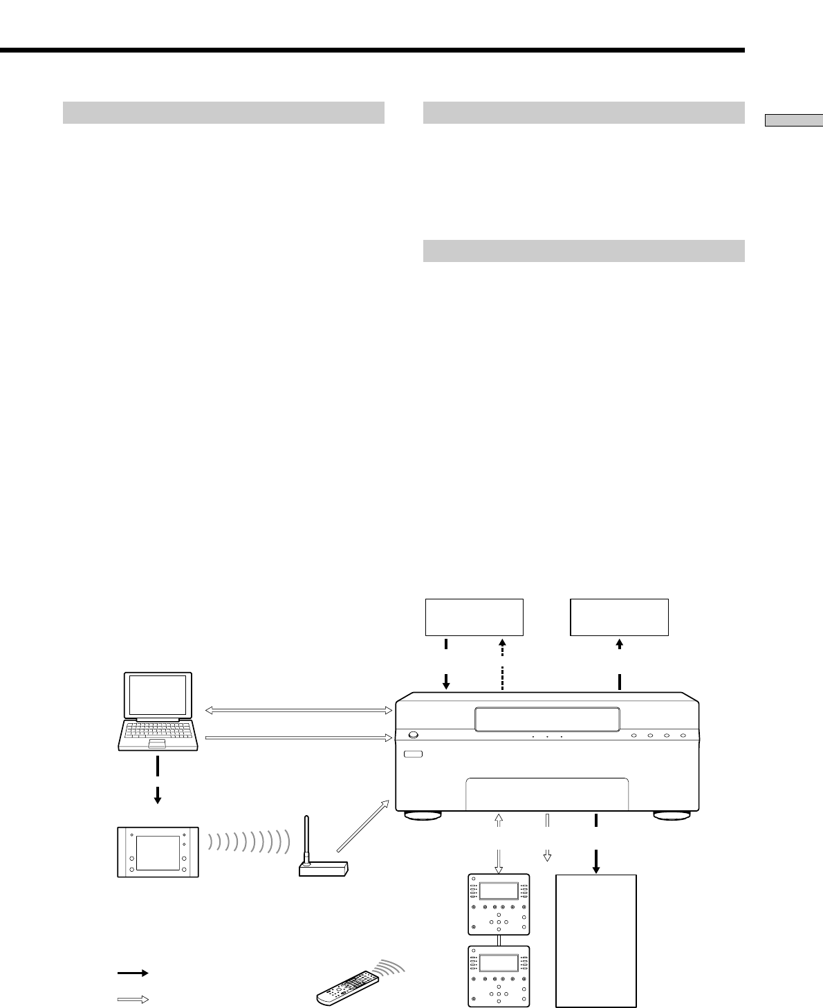
Features
You can control up to eight audio/video sources in up to
six zones with this Custom Integrated AV System. The
system consists of:
– a Main Unit
– an RF Remote Control
– Keypads (optional)
– IR Remote Controls for Keypads (optional)
You can enjoy the audio/video source and the output
components by using a Keypad in each zone and an RF
Remote Control in the main zone. This Custom Integrated
AV System allows you to
–Distribute audio/video signals from eight independent
sources to six separate zones.
–Control volume adjustment, such as muting, bass and
treble adjustments for each of the six zones.
–Control up to eight source components by using an RF
Remote Control, a Keypad, or via RS 232C commands.
5
Getting Started
Main Unit
•Zones: Up to six zones receive up to eight source
audio/video signals.
–Preamp Outs: Four fixed outputs for zones 1 to 4,
and two variable outputs for zones 5 and 6.
–Amplification: All six zones have built-in stereo
audio amplifiers at 30 Watts per channel.
–Video outputs for all six zones
–Keypad connections: RJ45 connectors for all six zones
using CAT5 cables
•Sources: Up to eight audio/video sources can be
selected by all six zones.
•Remote code entry: Remote code commands can be
learned by the Main Unit.
–on your computer
–on the Main Unit
•12 V trigger: Six zone-specific 12 V status outputs; each
300 mA max, total 1.2 A.
•RS232C port (Front): Allows you to connect the Main
Unit to your computer when you update the settings.
•RS232C ports (Rear): Allow you to connect a Sony DVD
Mega Changer and a Sony A/V Receiver to the Main
Unit.
Keypad
•LCD contrast adjustment.
•Connecting IR IN to an IR emitter enables you to use
the IR Remote Control for the additional range.
•RJ45 connectors enable you to use two Keypads in a
single zone.
RF Remote Control
•LCD panel configurable through your computer.
•Controls the audio/video sources in the main zone and
the other zones.
•Customize touch panels via an RS232C cable connected
to your computer.
Audio/Video
Sources 1 – 8
Audio/Video
Signal
Serial
RJ45 Zone
Status Audio/Video
Signal
Zones 1 – 6
IR
Zones 1 – 6
Display/Signal
Main
Keypad
Subsidiary
Keypad
IR Remote Control
for the Keypad
Computer
RS232C
Preset Commands
RF Antenna
Preset Commands
: Signal
: Command
RF Remote Control
AV Receiver
Audio/Video
Signal

6
Getting Started
Unpacking
The CAV-M1000ES system includes the following
components:
•CAV-M1000ES Main Unit
•RM-TP100 RF Remote Control
•Charger cradle for the RF Remote Control
•AN-M1000 RF Antenna
•AC power cord
•Plug-in 4-terminal screw-type connector for speaker (6)
•RF Antenna cable
•Installation Manual (this manual)
Optional Accessories:
RMR-K100 Keypad
•IR Remote Control
•Keypad mounting bracket
•Screws for fixing the Keypad to the Keypad mounting
bracket (2)
•Installation Guide
7
Getting Started
SOURCE SELECTZONE
RS232C
PROGRAM ENTER MODE BACK CANCEL
ZONE VOLUME MUTING
ALL ZONE
CHECK LEARN SETUP
12 3 4 5 6
q
f
q
d
q
s
q
a
q
;
987
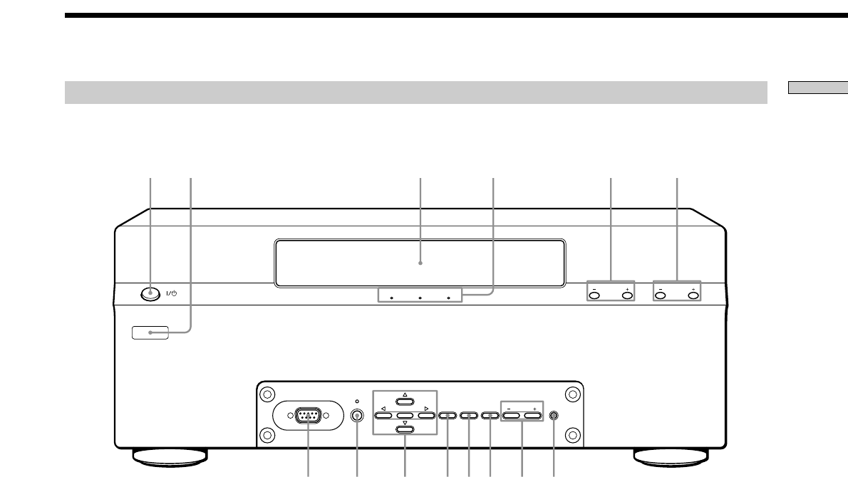
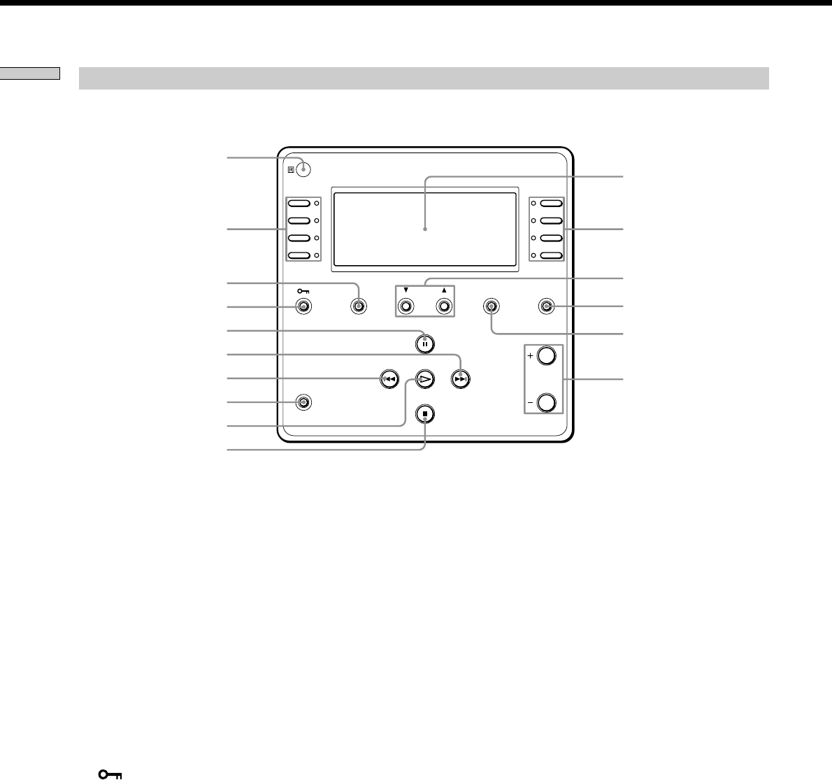
1?/1 (POWER) switch
Press to turn the power on or off.
2Learning IR window
Used to input remote codes into the Main Unit.
3 Display window
Displays various information.
4 Mode indicators
Display the current mode. These indicators turn off in
the NORMAL mode.
5 ZONE +/–
Press to select the zone in the NORMAL mode.
6 SOURCE SELECT +/–
Press to select the source component in the NORMAL
mode.
7RS232C connector
Used to update the firmware of the Main Unit and to
upload/download setup data from a computer using
an RS232C cross cable.
8 PROGRAM
Press to initiate a firmware update.
9 Cursor/ENTER
Press to select a menu.
0 MODE
Press repeatedly to select the mode of the Main Unit.
qa BACK
Press to return to the previous layer of the menu.
qs CANCEL
Press to cancel the present operation and return to the
NORMAL mode.
qd ZONE VOLUME +/–
Press to adjust the volume of the selected zone.
qf ALL ZONE MUTING
Press to set muting on or off in all zones.
Front panel of the Main Unit
Parts and Controls
8
Getting Started
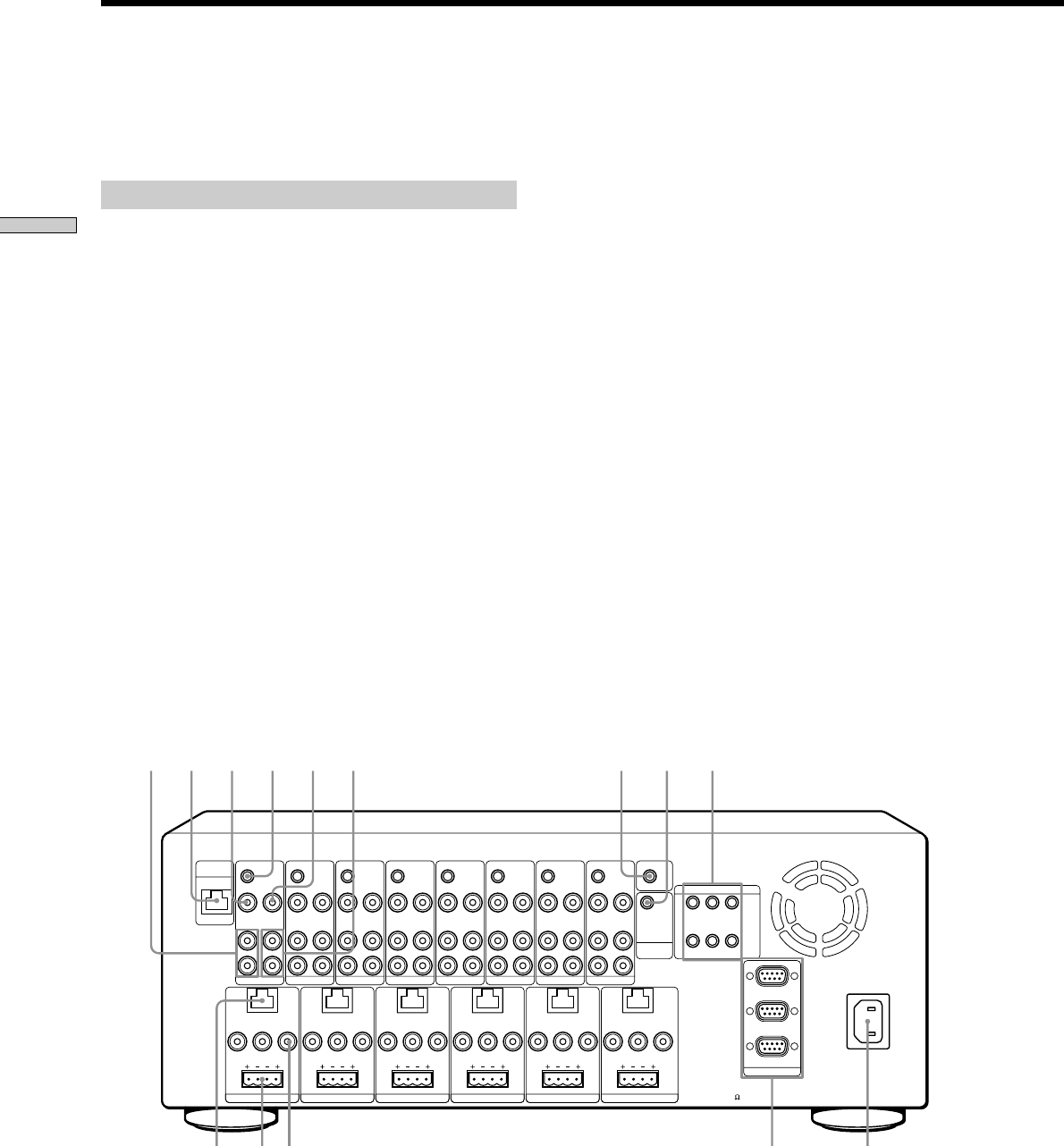
Parts and Controls
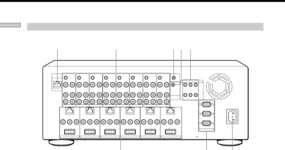
Rear panel of the Main Unit
qg RF ANTENNA (page 17)
Hooks up to the RF Antenna using a CAT5 cable, to
operate the RF Remote Control.
qh SOURCE connection jacks
a) IR OUT (page 16)
A 3.5 mm monaural mini phone jack for the
connection of an IR emitter to control the eight source
components individually. IR signals received from a
zone will be routed to the IR sensor of the source
component .
b) VIDEO IN (page 16)
An RCA jack for composite video input from a source
component.
c) VIDEO OUT (page 17)
An RCA jack for connecting a video source to another
local component.
Note
This is a buffered video connection, and this loop-through is
active even when the Main Unit is turned off, as long as the
AC power cord is plugged in.
d) AUDIO IN (page 16)
RCA jacks for stereo line level audio input from a
source component.
L
VIDEO IN
IR OUT
VIDEO OUT
AUDIO IN
KEYPAD
FIXED
PRE OUT
LR
RL
VIDEO OUT
SPEAKERS (CLASS II WIRING)
AUDIO OUT
R
SOURCE 1
ANTENNA
ZONE 1
L
VIDEO IN
IR OUT
VIDEO OUT
AUDIO IN AUDIO OUT
R
SOURCE 2
L
VIDEO IN
IR OUT
VIDEO OUT
AUDIO IN AUDIO OUT
R
SOURCE 3
L
VIDEO IN
IR OUT
VIDEO OUT
AUDIO IN AUDIO OUT
R
SOURCE 4
L
VIDEO IN
IR OUT
VIDEO OUT
AUDIO IN AUDIO OUT
R
SOURCE 5
L
VIDEO IN
IR OUT
VIDEO OUT
AUDIO IN AUDIO OUT
R
SOURCE 6
L
VIDEO IN
IR OUT IR OUT
COMMON
VIDEO OUT
AUDIO IN AUDIO OUT
R
SOURCE 7
L
123
VIDEO IN
IR OUT
VIDEO OUT
AUDIO IN AUDIO OUT
R
SOURCE 8
RS232C
~AC IN
STR
CONTROL
A1 II
12V TRIGGER
KEYPAD
FIXED
PRE OUT
LR
RL
VIDEO OUT
SPEAKERS (CLASS II WIRING)
ZONE 2
KEYPAD
FIXED
PRE OUT
LR
RL
VIDEO OUT
SPEAKERS (CLASS II WIRING)
ZONE 3
KEYPAD
FIXED
PRE OUT
LR
RL
VIDEO OUT
SPEAKERS (CLASS II WIRING)
ZONE 4
KEYPAD
VARIABLE
PRE OUT VARIABLE
PRE OUT
LR
RL
VIDEO OUT
SPEAKERS (CLASS II WIRING)
ZONE 5
KEYPAD
LR
RL
VIDEO OUT
SPEAKERS (CLASS II WIRING)
ZONE 6
456
DVP
AUX
SPEAKERS IMPEDANCE
USE 4-16
q
g
q
h
q
j
q
k
q
l
w; wa ws
e) AUDIO OUT (page 17)
RCA jacks for connecting an audio source to another
local component.
Note
This is a buffered audio connection, and this loop-through is
active even when the Main Unit is turned off, as long as the
AC power cord is plugged in.
qj IR OUT COMMON (page 17)
A 3.5 mm monaural mini phone jack for the
connection of an IR emitter to control any IR-
controlled component such as a lighting system or
motorized screen.
qk CONTROL A1 II (page 16)
Hooks up to a Sony source component equipped with
a matching jack allowing the Main Unit to control the
source component.
ql 12 V TRIGGER (page 17)
Provide control outputs of +12 V DC that turn devices
on and off in sync with the zone to drive voltage
sensing relay modules and AC strips.
9
Getting Started
w; ZONE connection jacks
a) KEYPAD (page 17)
An RJ-45 jack for the Keypad interface. Each connector
interfaces with the following: power, GND, and data
input/output.
b) VIDEO OUT (page 17)
An RCA jack that sends a source video signal selected
by the zone to the composite video input on a zone
display.
c) FIXED PRE OUT (zones 1 to 4)
An RCA jack for connecting zone audio output to an
external amplifier. For use with applications where
either more power is required for a zone, or for
passing signals to a Dolby Prologic-compatible
receiver for theater quality audio in one or more
zones.
d) VARIABLE PRE OUT (zones 5 and 6)
An RCA jack for connecting zone audio output to an
external power amplifier. The volume is attenuated via
VOLUME +/– on the Keypad.
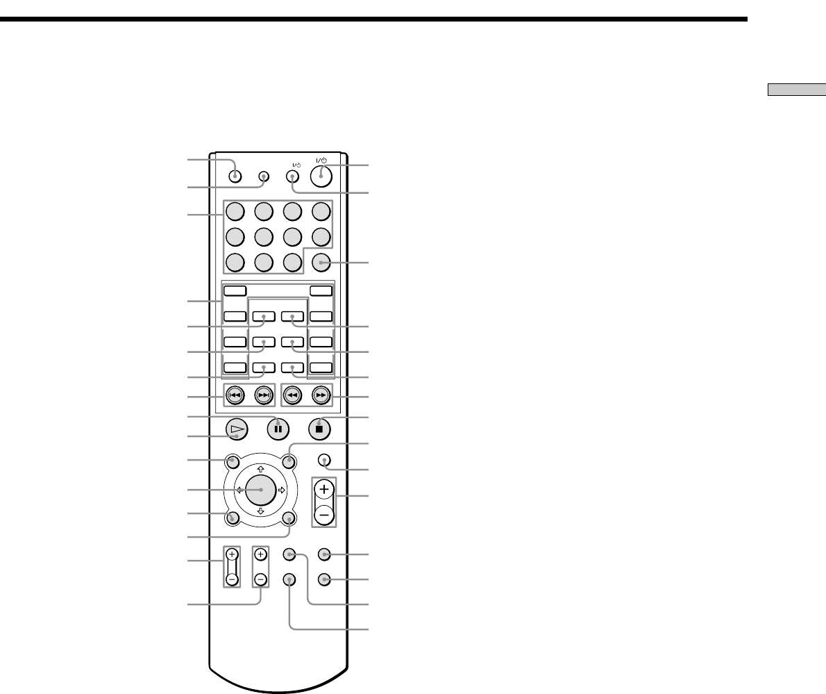
RF Remote Control
1 MUTING
Press to mute the audio.
2 VOLUME +/–
Press to adjust the volume.
3 SYSTEM OFF switch
Press to shut down the system.
CHANNEL
SYSTEM
VOLUME
MUTING
3
4
1
6
52
4 Cursor/ENTER
Press to control the source.
5 CHANNEL +/–
Press to control the source.
6 RS232C connector
Hook up a computer using an RS232C cable.
e) SPEAKERS (page 17)
A Plug-in 4-terminal screw-type jack which accepts
speaker cords sizes up to 12AWG.
Leave the AC power cord unplugged when you hook
up speaker cords.
wa RS232C (page 16)
Hook up to other RS232C components, allowing the
Main Unit to be controlled by other RS232C
components, or to control other components that
communicate via RS232C, such as a Sony DVD Mega
Changer or a Sony A/V Receiver. Use an RS232C cross
cable for the connection.
ws AC IN (page 17)
Hooks up the supplied AC power cord to AC IN.
10
Getting Started
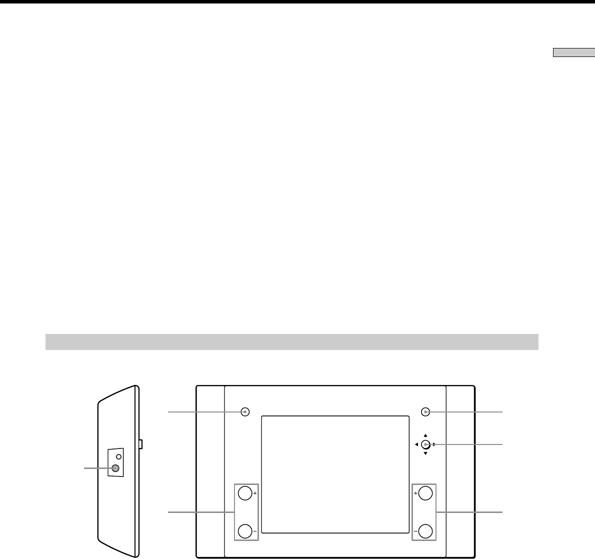
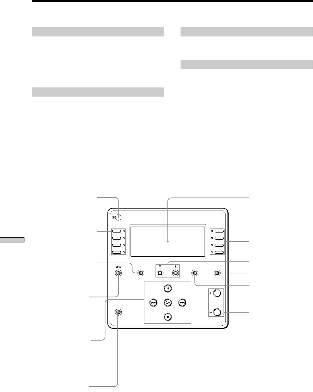
Front panel of the Keypad
1 IR sensor
Receives IR signals from the IR Remote Control for the
Keypad (supplied) to control both source components
and the system.
2 SELECT
Press to select a menu on the LCD display, such as a
source menu, a disc title list, etc.
3 PAGE
Press to return to the previous menu or to view the
current status of the disc title list and the preset station
list. If there is no list, only a source name will be
displayed.
4 (LOCK)
Press to lock the selected source component in.
5 X (PAUSE)
Press to pause the playback.
6 > (AMS)
Press to advance the track or to select a preset station.
7 .(AMS)
Press to go reverse the track or to select a preset
station.
PAGE SOURCE MUTING
VOLUME
POWER
qa
2
qs
qf
qd
qg
1
2
3
4
5
6
7
8
9
q;
8POWER switch
Press to turn the power of the Keypad on or off.
9 N (PLAY)
Press to operate the selected source.
0 x (STOP)
Press to stop playback.
qa Display window
Displays the selected source, the zone volume level,
the zone and the system status, and other system
status information.
qs SCROLL UP/DOWN
Press to scroll the LCD menu.
qd MUTING
Press to mute the speaker output in the zone.
qf SOURCE
Press to return to the source components list screen.
qg VOLUME +/–
Press to adjust the volume in a zone.
Parts and Controls
11
Getting Started
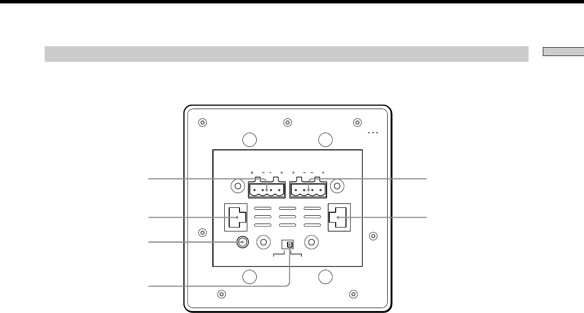
Rear panel of the Keypad
IR IN
OUT
R
TO SPEAKERS
L
IN
R
FROM AMPLIFIER
MODE
SUB
L
MAIN
w;qh
waqj
qk
ql
qh TO SPEAKERS (page 27)
Connects speaker cords to the speakers in a zone.
qj CAT5 OUT (page 27)
Connects a CAT5 cable to the CAT5 IN jack of the
subsidiary Keypad when used in a single room
qk IR IN (page 27)
Connects an optional IR cord so you can operate the IR
Remote Control for the Keypad by pointing it at the IR
sensor of the IR emitter.
ql MODE switch (page 27)
When using two Keypads in a single room, set this
switch to SUB on the subsidiary Keypad.
w; FROM AMPLIFIER (page 27)
Connect speaker cords to the Main Unit.
wa CAT5 IN (page 27)
Connects a CAT5 cable from the Main Unit to the main
Keypad.

12
Getting Started
Parts and Controls
IR Remote Control for Keypads
Buttons marked in grey are used to control the source
components.
1 SLEEP
Press to activate the sleep function that turns off the
Keypad automatically after the specified duration.
The time changes as shown below
2:00 t1:30 t1:00 t0:30 tOFF
2 DIMMER
Press repeatedly to change the brighteness of the LCD
backlight.
3 Numeral
Press to select a number, representing, for example, a
desired track of the source.
4 SELECT
Press to select a menu on the display on the LCD, such
as a source menu, a disc title list, etc.
5 LOCK
Press to lock the selected source component in.
6 PAGE
Press to return to the previous menu or to view the
current status of the disc title list or the preset station
list. If there is no list, only a source name will be
displayed.
7 DOWN
Press to scroll the LCD menu down.
8 ./> (AMS)
Press to locate a specific track of the source or to select
a preset station.
9 X (PAUSE)
Press to pause the playback of the source.
0 N (PLAY)
Press to operate the selected source.
qa TOP MENU/GUIDE
Press to display the top menu while using a source
component such as a DVD player.
qs CURSOR/ENTER
Press to select a menu while using a source component
such as a DVD player.
qd DISPLAY
Press to display on-screen messages from equipment
such as a DVD player.
qf RETURN/EXIT
Press to return to the previous menu screen (level) or
to quit the menu function while using a source
component such as a DVD player.
qg TV VOL +/–
Press to adjust the TV volume.
qh TV CH +/–
Press to change the TV channel.
qj ?/1 switch
Press to turn the Keypad on/off.
qk TV ?/1 switch
Press to turn the TV on/off.
ql ENTER
Press to confirm the selection.
w; DISC
Press to select a disc of a DVD/CD Mega Changer.
wa SOURCE
Press to return to the source components list screen.
ws UP
Press to scroll the LCD menu up.
wd m/M
Press to locate a portion you want to play within a
track of the source.
wf x (STOP)
Press to stop the current playback.
wg MENU
Press to display a menu while using a source
component such as a DVD player.
wh MUTING
Press to mute the speaker output in a zone.
wj VOLUME +/–
Press to adjust the volume in a zone.
wk F1
A button reserved for source components.
wl F2
A button reserved for source components.
e; FOLDER
Press to move to the FOLDER screen while using a
DVD player.
ea TV/VIDEO
Press to switch signals between TV input and Video
input.
13
Getting Started
1234
5678
90
>1 0
SLEEP DIMMER
ENTER
SELECT
LOCK DISC
PAGE SOURCE
DOWN
GUIDE
TOP MENU/ MENU MUTING
VOLUME
RETURN/EXITDISPLAY
TV VOL TV CH FOLDER F1
TV/VIDEO F2
UP
TV
1
2
3
4
5
qj
qk
ql
w;
6wa
7ws
8wd
wf
wg
wh
wj
wk
wl
e;
ea
9
q;
qa
qs
qd
qf
qg
qh
14
Getting Started
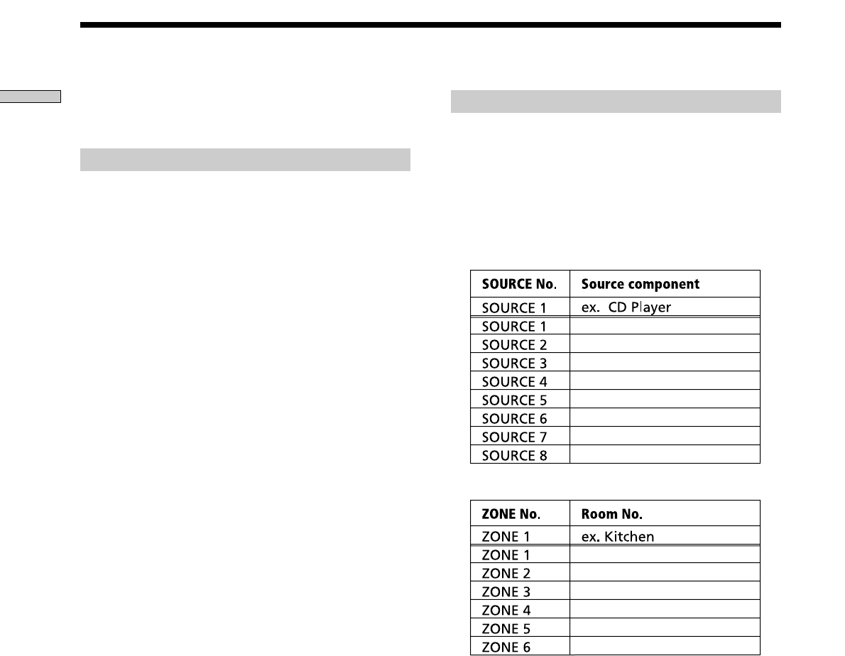
Before Customizing the System
Planning the system
Before setting up the system, plan the system
configuration.
1Decide the source components to be connected to
each SOURCE connection of the Main Unit.
2Decide the allocation of the components to be
used in each zone.
Be sure to read the following procedure thoroughly before
you actually make any settings.
Overview
The following chart gives an overview of how to set up
the Main Unit system.
Setting up the Main Unit
- Install the Main Unit. (page 15)
- Connect components, such as source components and
outut components, to the Main Unit. (page 16)
- Make other connections.
Setting up a Keypad
- Install the Keypad into a junction box. (page 25)
- Connect the Main Unit and the Keypad. (pae 17)
Customizing the Main Unit
- Customize the Main Unit on your computer. (page 19)
- Customize the Main Unit. (page 20)
Testing the components (page 29)
Setting up the RF Remote Control
- Customize the RF Remote Control on your computer.
For detailed information on the RF Remote Control, please
consult your nearest Sony dealer.
15
Setting up the Main Unit
Chapter 2
Setting up the
Main Unit
This chapter provides you with
information on the Main Unit
regarding installation, hookups and
settings.
Installing the Main Unit
When you mount the Main Unit, note the following:
•Place the Main Unit in a location with adequate
ventilation to prevent heat buildup and prolong the life
of the receiver.
•Do not place the Main Unit near heat sources, or in a
place subject to direct sunlight, excessive dust or
mechanical shock.
•Do not place anything on top of the cabinet that might
block the ventilation holes and cause malfunctions.
•Do not cover the rear panel.
•Use caution when placing the unit or speakers on
surfaces that have been specially treated (with wax, oil,
polish, etc.) as staining or discoloration of the surface
may result.
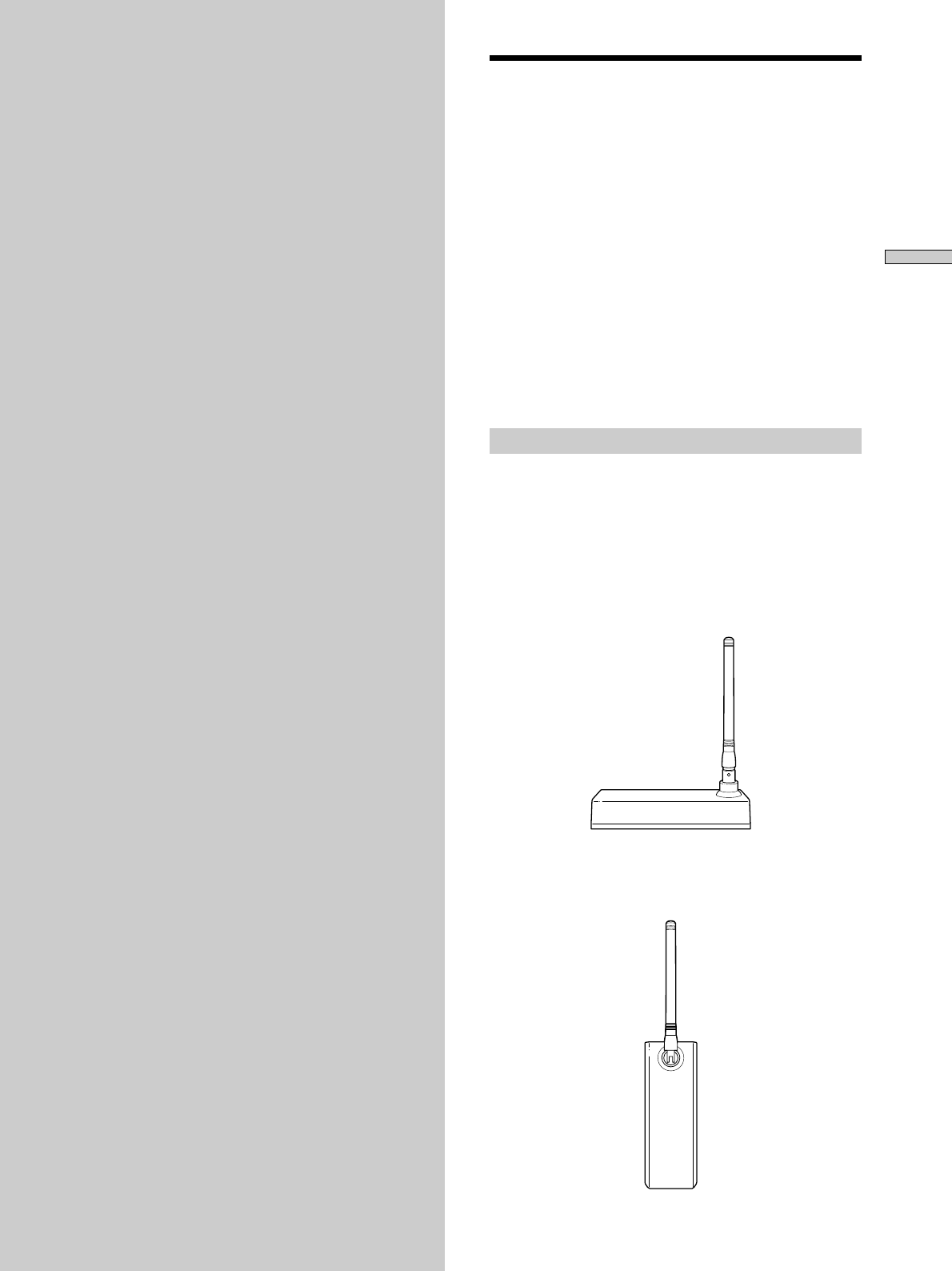
Installing the RF Antenna
Mount the RF Antenna in an appropriate place in the
room where the RF Remote Control is to be used.
For details on how to make the connection, refer to “RF
Antenna hookup” on page 17.
Horizontal position
Vertical position
16
Setting up the Main Unit
Before hooking up the Main Unit, be sure the power cord
is unplugged. Refer to the figures below for the
connections.
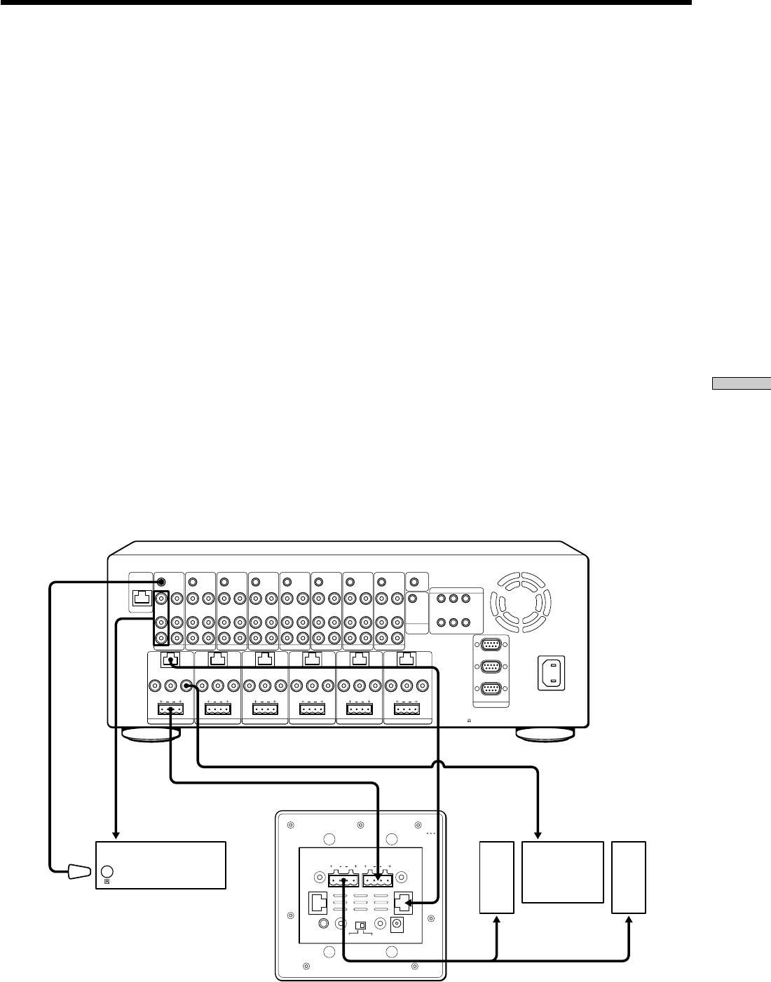
Source component hookups
AUDIO IN jack (A)
Hook up the audio output of each source component and
the AUDIO IN jack of each SOURCE connection jack of
the Main Unit.
Use RCA audio cables.
VIDEO IN jack (B)
Hook up the video output of each source component and
the VIDEO IN jack of each SOURCE connection jack of the
Main Unit.
Use an RCA video cable.
RS232C connector (C)
Hook up any RS232C equipped source component and
the RS232C connector of the Main Unit.
Use a DB9 cross cable.
You can control the connected RS232C components from
the Main Unit by sending commands.
Hooking up the Main Unit
CONTROL A1II jack (D)
Hook up each CONTROL A1II jack of the source
equipment such as XXXX and the Main Unit.
Use a CONTROL A1II cable.
You can control the connected source component from the
Main Unit.
IR OUT jack (E)
Plug the IR emitter into the IR OUT jack of each SOURCE
connection jack of the Main Unit. Be careful to match the
source audio and video connection number on the Main
Unit to the IR emitter connector number.
The IR control signal will be routed to the correct source
component. Find the IR sensor window on the source
component and attach the emitter to the component
sensor.
L
VIDEO IN
IR OUT
VIDEO OUT
AUDIO IN
KEYPAD
FIXED
PRE OUT
LR
RL
VIDEO OUT
SPEAKERS (CLASS II WIRING)
AUDIO OUT
R
SOURCE 1
ANTENNA
ZONE 1
L
VIDEO IN
IR OUT
VIDEO OUT
AUDIO IN AUDIO OUT
R
SOURCE 2
L
VIDEO IN
IR OUT
VIDEO OUT
AUDIO IN AUDIO OUT
R
SOURCE 3
L
VIDEO IN
IR OUT
VIDEO OUT
AUDIO IN AUDIO OUT
R
SOURCE 4
L
VIDEO IN
IR OUT
VIDEO OUT
AUDIO IN AUDIO OUT
R
SOURCE 5
L
VIDEO IN
IR OUT
VIDEO OUT
AUDIO IN AUDIO OUT
R
SOURCE 6
L
VIDEO IN
IR OUT IR OUT
COMMON
VIDEO OUT
AUDIO IN AUDIO OUT
R
SOURCE 7
L
123
VIDEO IN
IR OUT
VIDEO OUT
AUDIO IN AUDIO OUT
R
SOURCE 8
RS232C
~AC IN
STR
CONTROL
A1 II
12V TRIGGER
KEYPAD
FIXED
PRE OUT
LR
RL
VIDEO OUT
SPEAKERS (CLASS II WIRING)
ZONE 2
KEYPAD
FIXED
PRE OUT
LR
RL
VIDEO OUT
SPEAKERS (CLASS II WIRING)
ZONE 3
KEYPAD
FIXED
PRE OUT
LR
RL
VIDEO OUT
SPEAKERS (CLASS II WIRING)
ZONE 4
KEYPAD
VARIABLE
PRE OUT VARIABLE
PRE OUT
LR
RL
VIDEO OUT
SPEAKERS (CLASS II WIRING)
ZONE 5
KEYPAD
LR
RL
VIDEO OUT
SPEAKERS (CLASS II WIRING)
ZONE 6
456
DVP
AUX
SPEAKERS IMPEDANCE
USE 4-16
AMBEGF D LH
KI C N
J

17
Setting up the Main Unit
Output component hookups
AUDIO OUT jack (F)
Hook up the AUDIO OUT jack of each SOURCE
connection jack of the Main Unit and each audio input of
the external A/V receiver.
Use RCA audio cables.
VIDEO OUT jack (G)
Hook up the VIDEO OUT jack of each SOURCE
connection jack of the Main Unit and each video input of
the external A/V receiver.
Use RCA video cables.
IR OUT COMMON jack (H)
Plug the IR emitter into the IR OUT COMMON jack of the
Main Unit.
The IR control signal will be routed to the output
component (an auxiliary device that are not source
specific). Find the IR sensor window on the output
component and attach the emitter to the component
sensor.
Zone related cables hookups
SPEAKERS jack (I)
Hook up the SPEAKERS jack of each ZONE connection
jack of the Main Unit and the FROM AMPLIFIER jack of
each Keypad.
Use speaker cords terminated with plug-in 4-terminal
screw-type connectors.
Leave the AC power cord unplugged when you hook up
speaker cords.
VIDEO OUT jack (J)
Hook up the VIDEO OUT jack of each ZONE connection
jack of the Main Unit and the video input of the TV
monitor in each zone.
Use an RCA video cable.
KEYPAD jack (K)
Hook up the KEYPAD jack of each ZONE connection jack
of the Main Unit and the CAT5 IN jack of each Keypad.
Use a CAT5 cable.
12 V TRIGGER jack (L)
Hook up the 12 V TRIGGER jack of the Main Unit and
the device used to drive a voltage sensing relay module
and an AC strip.
Use a 3.5 mm mini phone cable.
RF Antenna hookup (M)
Hook up the RF ANTENNA jack of the Main Unit and the
jack of the RF Antenna.
Use a CAT5 cable.
AC power cord hookup (N)
Connect the supplied AC power cord to the AC IN jack.
18
Setting up the Main Unit
Selecting the Source and the Volume Level
of the Main Unit
Selecting the source for each zone
In the NORMAL mode, you can select a source
component for each zone. The status information for each
zone appears on the display window.
1Select a zone by pressing the ZONE + or ZONE –
button.
2Select a source component by pressing the SOURCE
+ or SOURCE – button.
The source component is confirmed one second after
you release the SOURCE button.
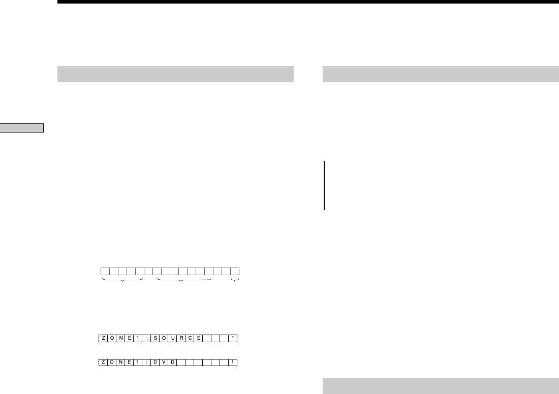
Example 1:
When a source component connected to the
SOURCE 1 Out/In plugs is selected in ZONE 1.
Example 2: When you connect a source component
whose title has changed from SOURCE 1 to
DVD in the PC SETUP mode.
Tip
Even when you connect several DVD players to the Main
Unit, you can distinguish each of them by the source number
displayed on the far right side in the display window.
ZONE1 : SOURCE 1
ZONE SOURCE Title SOURCE No
X
r
Adjusting the volume in each zone
1Press ZONE+ or ZONE – repeatedly to select a zone.
2Press ZONE VOLUME+ or VOLUME – to display the
current volume level.
The display window changes as shown below.
tVOLUME MIN
VOLUME 1
VOLUME 73
tVOLUME MAX
Note
The volume level displayed in the display window varies
depending on the volume limits you have set as described in
“Setting volume limits” on page 28.
3Press ZONE VOLUME+ or VOLUME – repeatedly to
adjust the volume to the desired level.
The display window returns to the NORMAL mode in
a few seconds after you have finished.
Note
In a zone where SOURCE INPUT OFFSET is ON, the actual
volume level is lower than the displayed volume level.
Turning ALL ZONE MUTING on or off
1Press ALL ZONE MUTING on the Main Unit.
“ALL ZONE MUTING” appears in the display
window.
2To turn ALL ZONE MUTING off, press ALL ZONE
MUTING again.
“MUTING OFF” appears for a few seconds, then the
display window returns to the previous display.
…

19
Setting up the Main Unit
Setting the baud rate – BAUD RATE SET
You can adjust the baud rate between the Main Unit and
an FM/AM Receiver (STR) or DVD Mega Changer
connected via an RS232C connection.
1Press MODE repeatedly until ”<<SETUP>>” appears
in the display window, then press ENTER.
2Press the R cursor or r cursor to select ”BAUD RATE
SET”.
3Press ENTER.
”WHICH PORT?” appears for a few seconds.
4Press the R cursor or r cursor to select a port.
Each time you press the R cursor or r cursor, the
display window changes cyclically as shown below.
WHICH PORT? (Appears for a few seconds)
Y
tFRONT RS232C R r
STR RS232C R r
DVP RS232C R r
tAUX RS232C R r
5Press ENTER.
The baud rate setting display appears.
6Press the R cursor or r cursor to select the desired
baud rate.
Each time you press the R cursor or r cursor, the
display window changes cyclically as shown below.
t9600 bps R r
14400 bps R r
19200 bps R r
38400 bps R r
57600 bps R r
115200 bps R r
t128000 bps R r
7Press ENTER when you have finished.
The display window returns to the NORMAL mode.
Setting up the Remote Code and the Baud Rate
– SETUP mode
Setting up the Main Unit connected to a
computer – PC SETUP
You can transfer setting data to the Main Unit and
customize it using an RS232C connection to your
computer.
The items that should be customized on your computer
are the following.
•The information needed to specify the source component,
output component, and remote code settings
•12V Trigger
Note
Do not connect speakers and a TV to the Main Unit while in
the PC SETUP mode.
1Connect the RS232C connector on the Main Unit to
your computer with an RS232C cross cable.
2Press MODE repeatedly until ”<<SETUP>>” appears
in the display window, then press ENTER.
“WHICH MENU?” appears for a few seconds.
3Select “PC SETUP” by pressing the R cursor or r
cursor.
Each time you press the R cursor or r cursor, the
display window changes as follows:
“PC SETUP R r”y“BAUD RATE SET R r”
4Press ENTER.
“READY!” appears in the display window. You are
now ready to transfer data between the Main Unit and
your computer.
5 <TBD> (STEP TAKEN ON THE PC)
6“PLEASE WAIT…” appears while data is being
transferred.
When the data has been transferred successfully,
“COMPLETED!” appears in the display window.
If the data transfer is unsuccessful, “FAILED!” appears
in the display window.
7Press ENTER when you have finished.

20
Setting up the Main Unit
Learning the Remote Code for a Connected Component
– LEARN Mode
You can enter any remote codes, even if the remote code
that you want to enter is not preset in the SETUP mode.
Learning the remote code - CODE
LEARNING
1Press MODE repeatedly until “<<LEARN>>” appears
in the display window, then press ENTER.
“WHICH MENU?” appears for a few seconds.
2Press the cursor R or rrepeatedly to select “CODE
LEARNING”, then press ENTER.
“CONNECT TO?” appears for a few seconds.
3Press the cursor R or r repeatedly to select the
desired component.
Each time you press the cursor R or r , the display
window changes cyclically as shown below.
CONNECT TO? (Appears for a few seconds)
r
tSOURCE 1 R r
SOURCE 8 R r
COMMON 1 R r
tCOMMON 10 R r
Notes
•The SOURCE or COMMON, which has already been
learned by the Main Unit in the PC SETUP mode, appears
with an exclamation mark ( ! ) at the left side of the display
window.
•Components that have not been connected to the Main Unit
are grayed out in the display window. You cannot select
them.
4Press ENTER.
“INPUT IR CODE” appears for a few seconds, then
display window changes to “CODE ID #001 R r”.
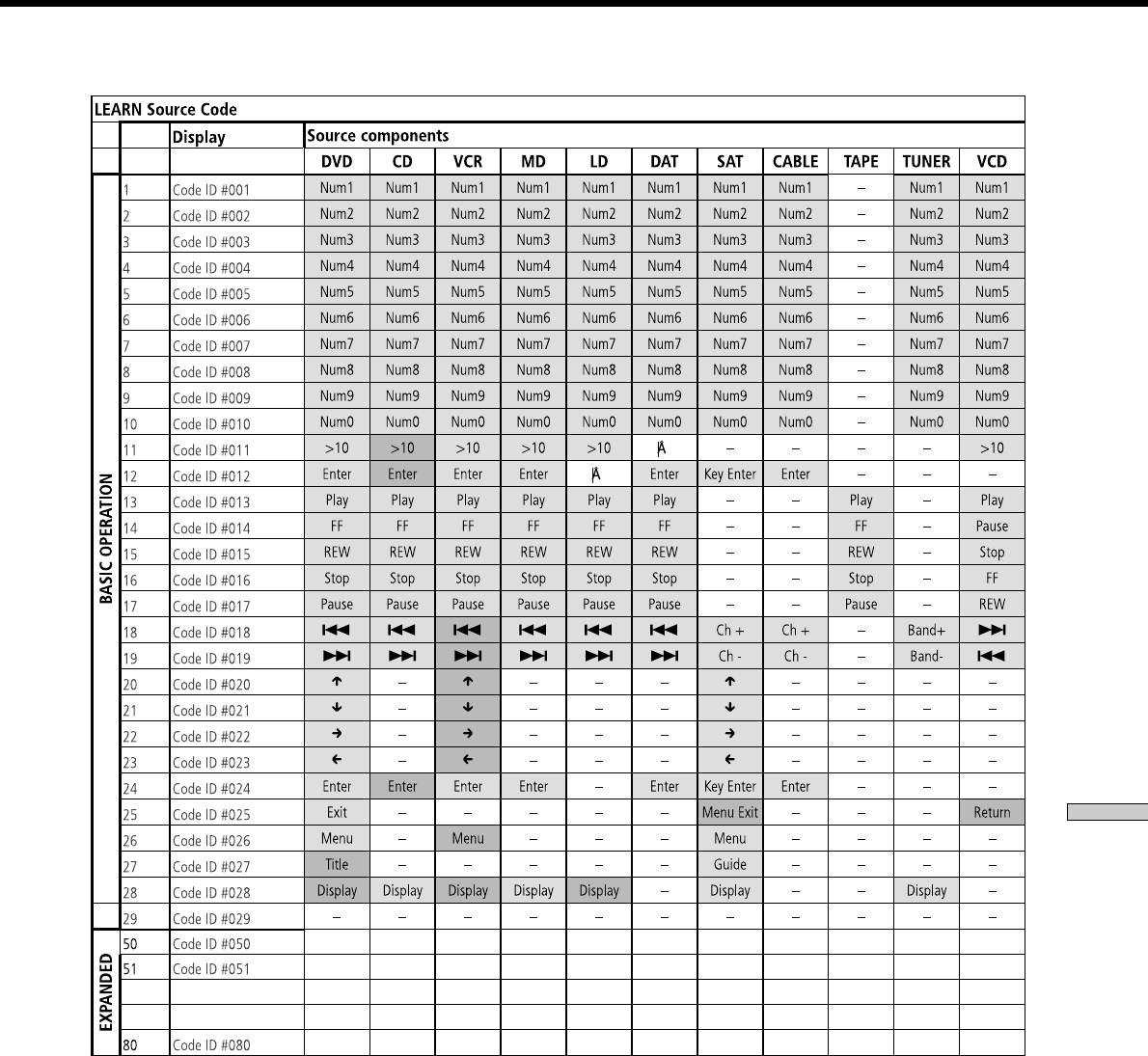
Note
Refer to “LEARN Mode Codes List” on page 34 to see the
code ID number corresponding to each IR command. For
example, “CODE ID #001” indicates “Power”.
5
While the code ID number is displayed in the
display window, press the corresponding button
on the remote control of the component while
pointing it toward the learning IR window of the
Main Unit.
When your entries are confirmed, “COMPLETED!”
appears for a few seconds, then the display window
moves to the next remote code entry.
If your entries are not confirmed, “LEARN FAILED!”
appears for a few seconds, then the failed code ID
number appears.
Tips
•When you want to skip the code ID number, press the
cursor r.
•When you want to re-enter the code ID, press the cursor R.
Notes
•When the remote code has been successfully learned, a “*”
will appear next to the remote code name.
•You can enter up to 50 remote codes into the Main Unit.
• You must complete step 5 within one minute after the
remote code name is displayed in the display window;
otherwise, your entry will not be learned and “LEARN
FAILED!” appears.
6
Repeat step 5 to enter other remote codes.
7
Press ENTER when you have finished.
“SETTING NOW…” appears for a few seconds. Then,
the display window returns to the NORMAL mode.
Notes
•Even if you quit the LEARN mode in the midst of making
the settings, the remote codes that have already been
learned will be stored.
•Some remote codes cannot be learned. In this case,
“MEMORY FULL” appears, then the display window
returns to the previous remote code entry. The remote
codes that have already been learned will be stored.
•The remote codes that have already been learned in the PC
SETUP mode are grayed out in the display window.
……

21
Setting up the Main Unit
You can add new remote codes using EXPAND CODE.
Adding a new remote key - EXPAND CODE
1Press MODE repeatedly until “<<LEARN>>” appears
in the display window, then press ENTER.
“WHICH MENU?” appears for a few seconds.
2Press the R cursor or r cursor to select “EXPAND
CODE”, then press ENTER.
“CONNECT TO?” appears for a few seconds.
3Press the R cursor or r cursor repeatedly to select
the desired component.
Each time you press the R cursor or r cursor, the
display window changes cyclically as shown below.
CONNECT TO? (Appears for a few seconds)
r
tSOURCE 1 R r
SOURCE 8 R r
COMMON 1 R r
tCOMMON 10 R r
Note
Remote codes that have not already been learned by the Main
Unit are grayed out in the display window. You cannot select
them.
4Press ENTER.
“INPUT IR CODE” appears for a few seconds, then
the display window changes to “CODE ID #100”.
5While the code ID number is displayed in the
display window, press the corresponding button
on the remote control of the component while
pointing it toward the learning IR window of the
Main Unit.
When your entries are confirmed, “COMPLETED!”
appears for a few seconds, then the display window
moves to the next remote code entry.
If your entries are not confirmed, “LEARN FAILED!”
appears for a few seconds, then the failed code ID
number appears.
Tips
•When you want to skip the code ID number, press the r
cursor.
•When you want to re-enter the code ID, press the R cursor.
Notes
•When the remote code is successfully learned, a “*” will
appear next to the remote code name.
•You can add up to 10 additional remote codes to the Main
Unit.
• You must complete step 5 within one minute after the
remote code name is displayed in the display window;
otherwise, your entry will not be learned and “LEARN
FAILED!” appears.
6Repeat step 5 to enter other remote codes.
7Press ENTER when you have finished.
“SETTING NOW…” appears for a few seconds.
The display window returns to the NORMAL mode.
Notes
•Even if you quit the LEARN mode in the midst of making
the settings, the remote codes that have already been
learned will be stored.
•Some remote codes cannot be learned. In this case,
“MEMORY FULL” appears, then the display window
returns to the previous remote code entry. The remote
codes that have previously been learned will be stored. You
cannot select them.
……

22
Setting up the Main Unit
You can check to see if the remote code of the source
component have been successfully learned by the Main
Unit.
1Press SOURCE – or SOURCE + to select the source
component that you want to check.
2Press MODE repeatedly until “<<CHECK>>“ appears
in the display window, then press ENTER.
“SET COMMAND” appears for a few seconds, then
the learned remote code appears.
3Press the cursor R or r repeatedly to select the
remote code that you want to check.
4Press ENTER.
The selected remote command will be performed.
Testing Learned Remote
Code – CHECK Mode
Viewing disc information
– DISC SEARCH
By connecting a Sony DVD Mega Changer to an RS232C
jack, or a Sony CD Mega Changer to CONTROL A1II, you
can view disc information, such as a disc title.
1Turn off the power.
2Press and hold MODE and the T cursor
simultaneously, and then turn on the power.
“DISC SEARCH” appears in the display window for a
few seconds, then, “DVD MEGA” appears.
3Press the R cursor or r cursor to select “DVD MEGA”
or “CD MEGA”.
4Press ENTER.
“SEARCHING NOW…” appears and flashes while the
Main Unit is searching for the disc information.
“COMPLETED!” appears after the information has
been received.
“FAILED!” appears when informations is not found or
cannot be read.
5Press ENTER when you have finished.
The display returns to the NORMAL mode.
Customizing the Main Unit
– INSTALLATION Mode

23
Setting up the Main Unit
Adjusting the source input offset
– SOURCE INPUT OFFSET
You can specify the maximum volume level to optimize
the acoustic conditions in each zone.
1Turn off the power.
2Press and hold ZONE + and ALL ZONE MUTING
simultaneously, and then turn on the power.
“SOURCE OFFSET” appears in the display window
for a few seconds.
3Press the R cursor or r cursor repeatedly to select a
source number.
Each time you press the R cursor or r cursor, the
display window changes cyclically as shown below.
SOURCE OFFSET (Appears for a few seconds)
r
tSOURCE 1 R r
Y
SOURCE 2 R r
tSOURCE 8 R r
4Press ENTER.
The display window displays the OFFSET settings.
5Press the R cursor or r cursor to adjust the offset.
Each time you press the R cursor or r cursor, the
display window changes cyclically as shown below.
tOFFSET 0dB R r
OFFSET -1dB R r
OFFSET -2dB R r
OFFSET -3dB R r
OFFSET -4dB R r
tOFFSET -5dB R r
6Press ENTER when you want to adjust the offset
for other source components.
The step goes back to step 3.
7Press CANCEL when you have finished.
The display window returns to the NORMAL mode.
Note
In a zone where SOURCE INPUT OFFSET is ON, the actual
volume level is lower than the displayed volume level.
…
Locking the settings – SETUP LOCK
You can lock in the settings under which have been
entered into the Main Unit.
1Turn off the power.
2Press and hold SOURCE SELECT + and BACK
simultaneously, and then turn on the power.
“SETUP LOCK” appears for a few seconds, then the
display window displays the SETUP LOCK window.
3Press the R cursor or r cursor to turn SETUP LOCK
on or off.
The display window changes as follows:
SETUP LOCK (Appears for a few seconds)
r
LOCK [OFF] R r
LOCK [ON] R r
4Press ENTER when you have finished.
The display window returns to the NORMAL mode.
Notes
•The following are the preferences that can be locked in in
the SETUP LOCK mode.
- All settings in the LEARN mode.
- All settings in the SETUP mode.
- Settings for the Disc Search.
- The adjustment of SOURCE OFFSET.
- All Clear.
•When you select settings that cannot be changed,
“LOCKED!” appears for a few seconds, then the display
window returns to the NORMAL mode.

24
Setting up the Main Unit
Viewing the version information
– CIS VERSION
CIS VERSION provides you the version information of
the Main Unit and other external components, such as an
FM/AM Receiver (STR), a DVD Mega Changer, an RF
Remote Control, or the Keypad.
1Turn off the power.
1Press and hold ZONE – and CANCEL simultaneously,
and then turn on the power.
“CIS VERSION” appears in the display window for a
few seconds.
2Press the cursor R or r to view the version
information.
Each time you press the button, the display window
changes as shown below.
CIS VERSION (Appears for a few seconds)
r
VERSION [X.XX]: displays the version information
of the Main Unit.
Y
STR [X.XX]: displays the version information
of the FM/AM RECEIVER (STR).
Y
DVD SYS. [X.XX]: displays the version information
of the DVD MEGA CHANGER
(system control).
Y
DVD IF. [X.XX]: displays the version information
of the DVD MEGA CHANGER
(interface control).
Y
RF RM [X.XX]: displays the version information
of the RF Remote Control.
Y
KEYPAD [X.XX]: displays the version information
of the Keypad.
r
NORMAL mode
Initializing all the settings – ALL CLEAR
Note that all memory data will be deleted when you
initiate an ALL CLEAR setting.
1Turn off the power.
2Press and hold SOURCE SELECT + and CANCEL
simultaneously, and then turn on the power.
“MEMORY CLEARING” appears in the display
window during the initialization.
When the initialization is completed, “MEMORY
CLEARED!” appears for four seconds, then the
display window returns to the NORMAL mode.
3Power will be turned off automatically after the
display window returns to the NORMAL mode.
Notes
•Any command keys other than POWER are not enabled during
the initialization of the Main Unit. If pressed, they are not
recognized.
•If you turn off the power before the initialization is completed,
the Main Unit will start initializing settings again when you
turn on the power the next time.
Customizing the Main Unit – INSTALLATION Mode
25
Setting up the Keypad
Chapter 3
Setting up the
Keypad
This chapter provides you with
information regarding installation,
hookup and settings for the optional
Keypad.
Installing the Keypad
A Keypad must be installed in a junction box (optional).
Follow the procedures below to mount a Keypad
mounting bracket and a Keypad on the wall.
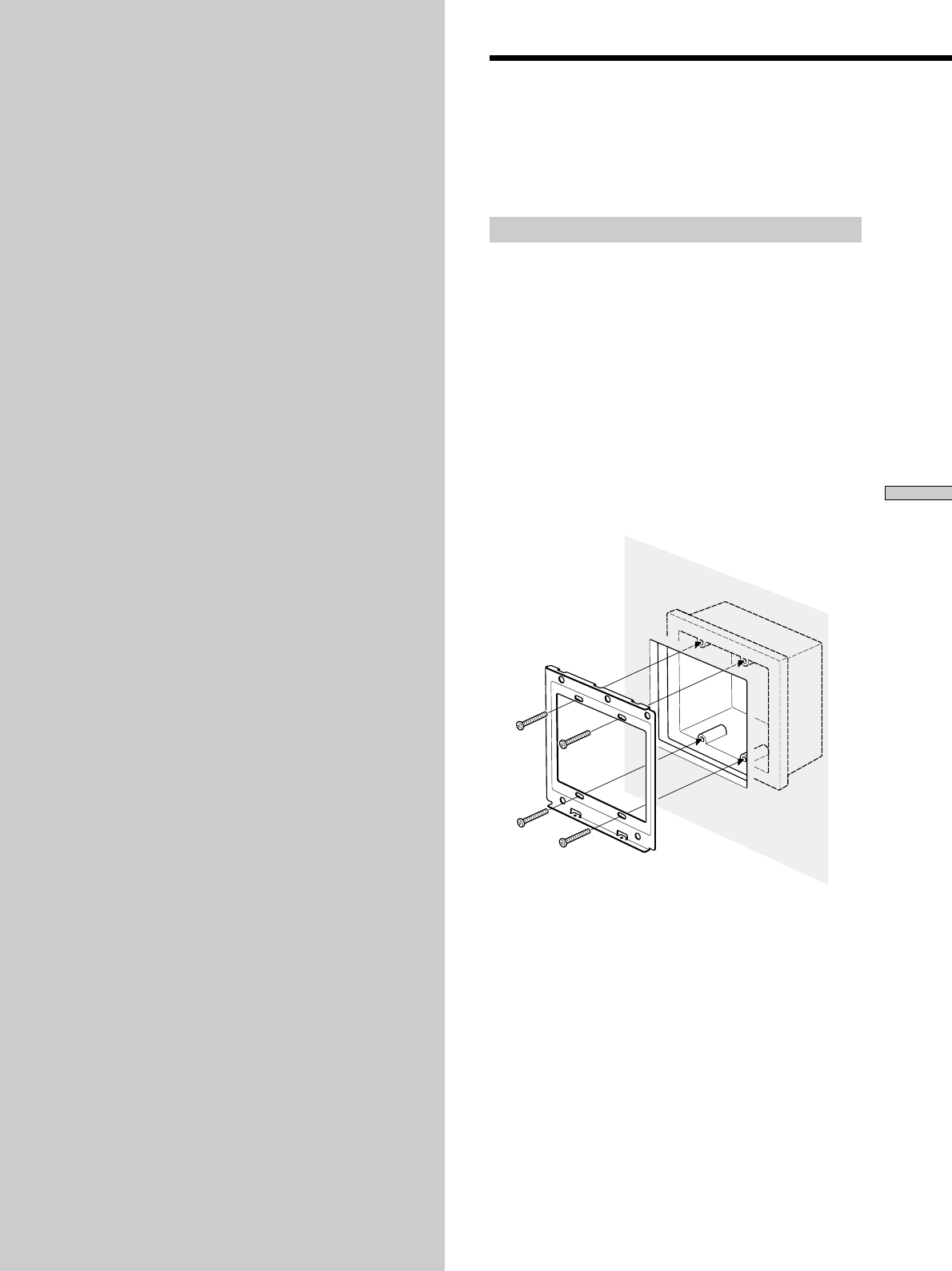
Installing the Keypad
1Place the Keypad mounting bracket over a junction
box which has already been installed on the wall
with the mounting lips facing out.
2Attach the Keypad mounting bracket to the
junction box with the supplied screws at the four
points as shown below.
Proceed to the steps in “Zone related cables hookups”
on page 17 before mounting the Keypad.
Note
The Keypad mounting bracket may not fit easily over some
junction boxes. In this case, loosen the screws and move the
Keypad mounting bracket left to right to center on the
junction box.
Setting up the Keypad
26
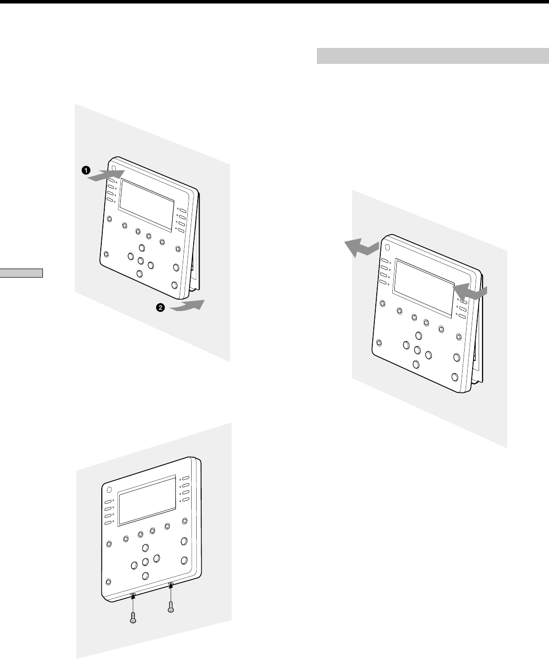
3Insert the top of the Keypad onto the mounting
bracket first, in the direction of the arrow 1 until
it clicks, then push the bottom of the Keypad onto
the bracket in the direction of the arrow 2.
4Fix and tighten the Keypad mounting screws as
shown below.
5When you have finished mounting the Keypad,
check that it operates properly.
Removing the Keypad
1Remove the screws that hold the Keypad and the
Keypad mounting bracket.
2Press and hold the edge of the upper-side of the
Keypad tightly. Pull the lower part of the Keypad
away from the Keypad mounting bracket first,
then pull the upper part of the Keypad out
slightly, lifting it in the direction of the arrow, as
shown below.
Note
You may need some extra effort to remove the Keypad from
the wall since there are various kinds of junction boxes, and
the installation environment of the Keypad differs.
Installing the Keypad
Setting up the Keypad
27
You must install at least one Keypad and a pair of
speakers in each zone. In the zones where both audio and
video will be installed, you must install at least one TV
monitor.
Requirements for these hookups are as follows.
•A CAT5 cable has been installed for each zone's Keypad.
•Two pairs of 12 to 18 AWG speaker cords for each pair of
speakers.
•An RCA video cable for a TV monitor from each zone to
the Main Unit location.
TV monitor hookup
Hook up the video input of the TV monitor in each zone
and the VIDEO OUT of each ZONE connection jack of the
Main Unit.
Use an RCA video cable.
Speakers hookup
1Hook up the speaker cords from the SPEAKERS jack
of each ZONE connection jack of the Main Unit to
the FROM AMPLIFIER jack of the Keypad in each
zone.
2Hook up the speaker cords from the TO SPEAKERS
jack of the Keypad to the speaker terminals in each
zone.
Notes
• Use speakers which have a combined impedance of
between 4 and 16 Ohms loaded.
• Twist the stripped ends of the speaker cords about
2/3 inch (10 mm). Be sure to match the speaker cord
to the appropriate terminal on the components: + to
+ and – to –. If the cords are reversed, the sound will
be distorted and will lack bass.
• 14 AWG speaker cords are recommended for
speaker runs up to 150 feet (45 m). The 4-terminal
connectors accept speaker cords sizes up to 12 AWG,
maximum.
•If you use speakers with a low maximum input
rating, adjust the volume carefully to avoid
excessive output on the speakers.
Hooking up in Each Zone
CAT5 cable hookup
1Set the MODE switch to MAIN on the rear panel of
the Keypad.
2Hook up the CAT5 cable from the KEYPAD jack of
each ZONE connection jack of the Main Unit to the
IN jack of the Keypad in each zone.
To install two Keypads in the same zone
You can install two Keypads in a single room.
1Set the MODE switch to SUB on the rear panel of
the subsidiary Keypad.
2Hook up the CAT5 cable from the OUT jack of the
Keypad for which the MODE switch is set to MAIN,
to the IN jack of the subsidiary Keypad.
Note
Note that the length of CAT5 cables for each connection is
limited. See the figure below for the maximun length of CAT5
cables.
IR emitter hookup
When you want to use the IR Remote Control for the
Keypad without pointing at the IR sensor of the Keypad,
plug an IR emitter (optional) into the IR IN jack of the
Keypad.
You can operate the IR Remote Control for the Keypad
pointing at the IR sensor of the IR emitter.
Main Unit Keypad
275 feet max.
Main Unit Keypad Keypad
150 feet max. 50 feet max.
Setting up the Keypad
28
Customizing the Keypad
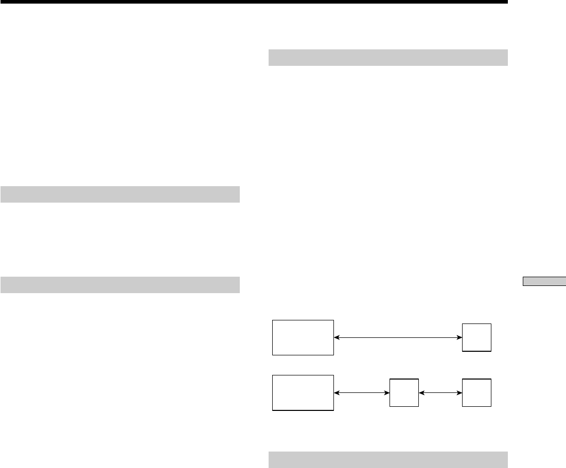
Setting bass and treble
You can adjust bass and treble to optimize the acoustic
conditions in each zone.
1Turn off the power.
2Press and hold MUTING and LOCK simultaneously,
and then press POWER.
The LCD panel changes to the Bass and Treble setup
mode.
3Press the corresponding SELECTION button to
adjust the bass and the treble.
4Turn off the power when you have finished.
The settings are confirmed when the power is turned
off.
Notes
•All buttons, other than VOLUME +, VOLUME –, MUTING
and POWER, are disabled while you are making settings.
•You can adjust Bass and Treble between ± 14 dB and 2 dB.
Setting volume limits
You can customize the volume limits to protect speakers
from being over driven.
1Turn off the power.
2Press SOURCE and PAGE simultaneously, and then
press POWER.
The LCD touch panel changes to the Volume
limitation mode.
3Press the corresponding SELECTION button to
adjust the maximum volume.
4Turn off the power when you have finished.
The settings are confirmed when the power is turned
off.
Notes
•All buttons, other than VOLUME +, VOLUME –, MUTING,
and POWER, are disabled while you are making settings.
•You can adjust the volume limits between level 64 and level
74.
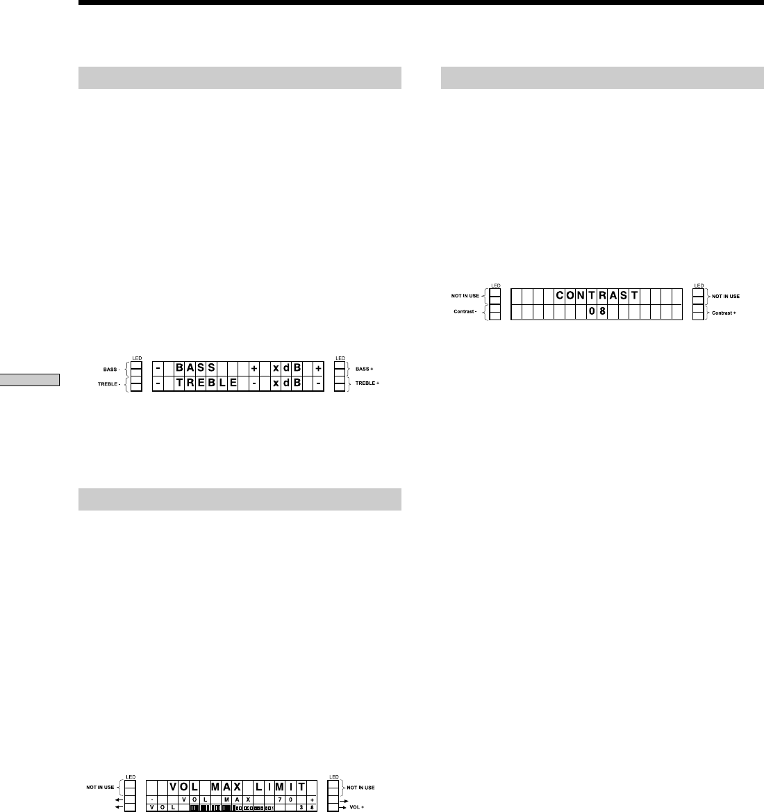
Adjusting LCD contrast
1Turn off the power.
2Press and hold PLAY and the SELECT button in the
left-upper simultaneously, and then press POWER.
The display window enters the contrast setting mode.
3Press the corresponding SELECTION buttons to
adjust the LCD Contrast Value.
4Turn off the power when you have finished.
The settings are confirmed when the power is turned
off.
Notes
•All buttons other than POWER are disabled while settings
are being made.
•You can adjust the LCD contrast between level 01 and level
32.
Setting up the Keypad
29
It is recommended that you test all the components before
you finish with the installation of the entire system in
each zone so as not to encounter any problems after the
installation is completed. Check to see if the Main Unit,
the installed components, and the Keypad operate
properly by testing each operation.
1Check the following connections.
- All the Keypads are connected to the Main Unit via CAT5
cables.
- An audio or a video component is connected between
AUDIO IN Left/Right and VIDEO IN of each SOURCE
connection jack.
- A display (output component) is connected to VIDEO OUT
at each ZONE connection jack.
- Speakers are connected to SPEAKERS at each ZONE
connection jack.
- An IR emitter is connected to IR OUT of each SOURCE
connection jack, and is placed near the IR sensor of the
source component.
- AC power cords for the Main Unit and the other
components are plugged in.
2Turn on the Main Unit.
3Select ZONE 1 by pressing the ZONE button on the
front panel of the Main Unit.
Testing the Components
4Select SOURCE 1 by pressing the SELECT SOURCE
button on the front panel of the Main Unit.
5Turn on the Keypad in zone 1.
6Select SOURCE 1 by pressing the SELECT button on
the Keypad. Then, check the following.
- Power control
Press POWER to turn the Keypad on or off.
- Volume adjustment
Press VOLUME +/– to adjust the volume.
- Muting
Press MUTING to mute the speaker output.
- Playback operation
Press the Play, Stop, Pause, and AMS (./>) buttons
on the Keypad to confirm that the source component
operates properly.
- Remote control operation
Check that the remote control of the SOURCE 1 component
works by pressing any command button while pointing
the Remote Control toward the IR sensor of the Keypad.
Then check that the SOURCE 1 component operates
properly using the remote control.
7Perform the test in each zone from zone 1 through
zone 6 by repeating Steps 3 to 6.
L
VIDEO IN
IR OUT
VIDEO OUT
AUDIO IN
KEYPAD
FIXED
PRE OUT
LR
RL
VIDEO OUT
SPEAKERS (CLASS II WIRING)
AUDIO OUT
R
SOURCE 1
ANTENNA
ZONE 1
L
VIDEO IN
IR OUT
VIDEO OUT
AUDIO IN AUDIO OUT
R
SOURCE 2
L
VIDEO IN
IR OUT
VIDEO OUT
AUDIO IN AUDIO OUT
R
SOURCE 3
L
VIDEO IN
IR OUT
VIDEO OUT
AUDIO IN AUDIO OUT
R
SOURCE 4
L
VIDEO IN
IR OUT
VIDEO OUT
AUDIO IN AUDIO OUT
R
SOURCE 5
L
VIDEO IN
IR OUT
VIDEO OUT
AUDIO IN AUDIO OUT
R
SOURCE 6
L
VIDEO IN
IR OUT IR OUT
COMMON
VIDEO OUT
AUDIO IN AUDIO OUT
R
SOURCE 7
L
123
VIDEO IN
IR OUT
VIDEO OUT
AUDIO IN AUDIO OUT
R
SOURCE 8
RS232C
~AC IN
STR
CONTROL
A1 II
12V TRIGGER
KEYPAD
FIXED
PRE OUT
LR
RL
VIDEO OUT
SPEAKERS (CLASS II WIRING)
ZONE 2
KEYPAD
FIXED
PRE OUT
LR
RL
VIDEO OUT
SPEAKERS (CLASS II WIRING)
ZONE 3
KEYPAD
FIXED
PRE OUT
LR
RL
VIDEO OUT
SPEAKERS (CLASS II WIRING)
ZONE 4
KEYPAD
VAR IABL E
PRE OUT VARIABLE
PRE OUT
LR
RL
VIDEO OUT
SPEAKERS (CLASS II WIRING)
ZONE 5
KEYPAD
LR
RL
VIDEO OUT
SPEAKERS (CLASS II WIRING)
ZONE 6
456
DVP
AUX
SPEAKERS IMPEDANCE
USE 4-16
IR IN
OUT
R
TO SPEAKERS
L
DC IN
IN
R
FROM AMPLIFIER
MODE
SUB
L
MAIN
DVD player
Ke
y
pad
SP TV SP

30
Chapter 4
Other
Information
This chapter provides you with
additional information that will help
you understand and maintain your
system.
Precautions
On safety
•Should any solid object or liquid fall into the cabinet, unplug
the player and have it checked by qualified personnel before
operating it any further.
•The AC power cord must be changed only at a qualified
service shop.
•The unit is not disconnected from the AC power source
(mains) as long as it is connected to the wall outlet, even if the
unit itself has been turned off.
On power sources
•Before operating the unit, check that the operating voltage of
the unit is identical to that of your local power supply. The
operating voltage is indicated on the nameplate on the back of
the unit.
•If you are not going to use the unit for a long time, be sure to
disconnect it from the AC power source (mains). To disconnect
the mains lead, grasp the plug itself; never pull the cord.
On placement
•Place the unit in a location with adequate ventilation to
prevent heat build-up in the Main Unit.
•Do not place the unit on a soft surface such as a rug that might
block the ventilation holes on the bottom.
•Do not place the unit in a location near heat sources, or in a
place subject to direct sunlight, excessive dust, or mechanical
shock.
On adjusting the volume
•Do not turn up the volume too much while listening to audio
with very low input levels or no audio signals. If you do, the
speakers may be damaged when a peak level portion is played.
On cleaning
•Clean the cabinet, panel, and controls with a soft cloth slightly
moistened with a mild detergent solution. Do not use any type
of abrasive pad, scouring powder, or solvent, such as alcohol
or benzine.
If you have any questions or problems concerning the
Main Unit, please consult your nearest Sony dealer.

31
Other Information
Troubleshooting
If you experience any of the following difficulties while
using the player, use this troubleshooting guide to help
you to remedy the problem. Should any problem persist,
consult your nearest Sony dealer.
There is no sound, no matter which component is
selected.
,Check that both the Main Unit and all components
are turned on.
,Check that all speaker cords are connected
correctly.
,Press MUTING to cancel the muting function.
There is no sound from a specific component.
,Check that the component is connected correctly to
the audio input jacks for that component.
,Check that the cord(s) used for the connection is
(are) fully inserted into the jacks on both the
receiver and the component.
There is no sound, or only a very low-level sound
is heard.
,Check that the speakers and components are
connected securely.
,Check that you have selected the correct
component on the Main Unit.
,Press MUTING if the muting function is activated.
,The protective device on the Main Unit has been
activated because of a short circuit. Turn off the
Main Unit, eliminate the short-circuit problem and
turn the power on again.
The left and right sounds are unbalanced or
reversed.
,Check that the speakers and components are
connected correctly and securely.
,Adjust the balance parameters on each Keypad.
There is severe hum or noise.
,Check that the speakers and components are
connected securely.
,Check that the connecting cords are away from a
transformer or motor, and at least 3 meters away
from a TV set or fluorescent light.
,Move your TV away from the audio components.
,The plugs and jacks are dirty. Wipe them with a
cloth slightly moistened with alcohol.
There is no picture, or an unclear picture appears
on the TV screen or monitor.
,Select the appropriate input on the Main Unit.
,Set your TV to the appropriate input mode.
,Move your TV away from the audio components.
The RF Remote Control does not function.
,Make sure the RF antenna is connected securely to
the Main Unit and placed in an appropriate
position.
,Make sure you have selected the correct function
on the Remote Control.
The IR Remote Control for the Keypad does not
function.
,Point the Remote Control at the remote sensor
on the Keypad.
,Remove any obstacles in the path between the
Remote Control and the Keypad.
,Replace both batteries in the Remote Control with
new ones, if they are weak.
,Check that you have selected the correct function
on the Remote Control.
The source component does not respond to the
Keypad operation.
,Check that the IR emitter is connected to the IR
OUT jack of the Main Unit.
,Check that the IR emitter is connected to the
corresponding IR OUT jack of the source
component.
,Check that the IR emitter is connected to the IR
sensor of the source component.
,Check that the remote codes have been
successfully learned by the Main Unit in the PC
SETP mode and the LEARN mode.

32
Other Information
Error Messages
Main Unit
If any of the messages below appear on the Display window of the Main Unit, check the following.
Message Cause Corrective action
PROTECTOR ZONE1 Protective device in zone 1 has been activated. Ask your nearest Sony dealer.
PROTECTOR ZONE2 Protective device in zone 2 has been activated. Ask your nearest Sony dealer.
PROTECTOR ZONE3 Protective device in zone 3 has been activated. Ask your nearest Sony dealer.
PROTECTOR ZONE4 Protective device in zone 4 has been activated. Ask your nearest Sony dealer.
PROTECTOR ZONE5 Protective device in zone 5 has been activated. Ask your nearest Sony dealer.
PROTECTOR ZONE6 Protective device in zone 6 has been activated. Ask your nearest Sony dealer.
FAN STOP
The fan does not rotate. Ask your nearest Sony dealer.
CONNECTION ERROR
A communication error with the AV receiver An error occurred due to an unsupported connection.
STR
has (STR) occurred.
CONNECTION ERROR
A communication error with the DVD MEGA An error occurred due to an unsupported connection.
DVD MEGA
CHANGER has occurred.
CONNECTION ERROR
A communication error with the computer has An error occurred due to an unsupported connection.
PC
occurred.
CONNECTION ERROR
A confirmation error with the RF Remote Ask your nearest Sony dealer.
RF REMOTE
Control has occurred.
EEP ACCESS FAIL
The Main Unit failed to access the EEPROM. Ask your nearest Sony dealer.
MEMORY FULL
The Memory capacity for storing EEPROM Some remote codes cannot be learned even if the memory
code has been exceeded during the remote capacity used for learning has not been exceeded.
code learning.
Keypad
If any of the messages below appear on the display window of the Keypad, check the following.
Message Cause Corrective action
CONNECTION NOT The Keypad failed to communicate with Turn off the Main Unit and check the CAT5 connections.
ESTABLISHED the Main Unit.
PROTECTOR Protector is detected by the Main Unit. Turn off the Main Unit and check the speaker connections.
FAN STOP The fan of the Main Unit does not rotate. Turn off the Main Unit and check that the ventilation holes
are not covered.
PLEASE CHECK Mode selector switch setting is wrong. Check that the Mode switch on the rear panel of the
MODE SELECTOR Keypad is in the correct position.
CANNOT ACCESS NOW Multiple Keypads tried to access Wait for a few seconds and try again.
the same source component.
SOURCE NOT AVAILABLE! An inactive source was selected. Select the appropriate source connected to the Main Unit.
LOCKED BY OTHER ZONE
The selected source was locked by another You cannot operate a locked source until it is unlocked.
zone.
LOCKED BY MAIN ZONE
The selected source was locked by the main You cannot operate a locked source until it is unlocked.
zone.
NOT USED
An inactive button was selected. Some buttons are not assigned for certain sources.
ex.) PLAY cannot be operated in the TUNER position.

33
Other Information
Specifications
CAV-M1000ES Main Unit
Audio (each channel)
Continuous average power output (FTC)
All channels: 30 W per channel min. RMS at 8 ohms,
any two channels driven from 20 Hz
to 20 kHz with no more than 0.09 %
HD.
Frequency response: 5 Hz to 70 kHz ± 3dB
Input sensitivity: 160 mV for 1 W output, 890 mV for full
output (30 W) with volume control
set to maximum.
Input impedance: 20 k ohms
Power output: 35 W RMS (4 - 8 ohms)
Signal-to-noise ratio: >92 dB (A-weighted )
Bass control range: 100 Hz ± 12 dB, 2 dB step
Treble control range: 10 kHz ± 12 dB, 2 dB step
Loop OUT/Pre OUT
Frequency response: 5 Hz to 55 kHz ± 3dB
THD @ 2 V: <0.08 %
Signal-to-noise ratio: 102 dB (A-weighted @ 2 V)
Video
Input/output impedance:
75 ohm
Video insertion loss: 0 dB (50 Hz - 6 MHz)
General
12V trigger: 300mA max each zone, total 1.2A max
Power requirements: 120 V 60 Hz
Power consumption: 540 W
Dimensions: 430 mm ✕ 433 mm ✕ 175 mm
(W ✕ D ✕ H)
Mass: 24 kg
RM-TP100 RF Remote Control
Audio (each channel)
Operating system: Liquid crystal touch panel
Liquid crystal size: 3.8 inches
(256 ✕ 200 dots)
Liquid crystal type: Reflection system
(Monochrome type)
Touch panel: Resistant membrance system
Analog type
Power requirements: Rechargeable
(Ni-MH) battery
Maximum external dimensions:
166 mm ✕ 25 mm ✕ 126 mm (W ✕ D ✕
H, including projecting parts and
controls)
Mass: 392 g (Main unit only, including the
rechargeable battery)
Design and specifications are subject to change without notice.

34
Chapter 5
Appendix
This chapter provides you with
remote code lists and concise
information about operating the
system.
LEARN Mode Code List
35
Appendix

36
Appendix
LEARN Mode Code List

37
Appendix
A
AC IN 9,17
AC power cord 9, 17, 38
Adding a new remote key 21
Adjusting
Volume 38, 39, 40
Source input offset 23
ALL CLEAR 24
ALL ZONE MUTING button 7, 18
AMS button 10, 12
AUDIO IN jack 8, 16
AUDIO OUT jack8, 17
B
BACK button 7
Bass 28
Battery 38
BAUD RATE SET19
C
CANCEL button 7
CAT5 IN jack 11
CAT5 OUT jack 11
Charging the battery 38
CHANNEL +/- button 9
CHECK mode 22
CIS VERSION 24
CODE LEARNING 20
CONTROL A1II jack 8, 16
Cursor/ENTER button 7, 9, 12
Customizing
Keypad 28
Main Unit 22
D, E, F
DIMMER button 12
DISC
Button 12
DISC SEARCH 22
Information 22
DISPLAY button 12
Display window 7,10
ENTER button7,9,12
Error messages 32
EXPAND CODE 21
Index
F1 button 12
F2 button 12
FIXED PRE OUT jack 9
FOLDER button 12
FROM AMPLIFIER jack 11
H, I
Hookup
AC power cord17
Keypad 17,27
IR emitter 17
Output components 27
RF Antenna 17
Source components 16
Speaker 27
TV monitor 27
Zone related cables 17
Initializing all the settings 24
INSTALLATION mode 22
Installing
Keypad 25
Main Unit 15
RF Antenna 15
IR IN jack 11
IR OUT jack 8,16,17
IR Remote Control 12,40
IR sensor 10
K, L, M
Keypad 9, 25, 39
KEYPAD jack 9,17
LCD contrast 28
Learning the remote code 22
LEARN mode code list 34
LOCK button 10
Locking the settings 23
MENU button 12
MODE button 7
MODE switch 11
Mode indicator 7
MUTING button 9,10,12

38
Appendix
P
PAGE button 10, 12
PAUSE button 10, 12
PC SETUP 19
Planning the system 14
PLAY button 10, 12
POWER switch 7, 10
Precautions 30
PROGRAM button 7
R
Removing the Keypad 26
RS232C connector 7, 9, 16
RF Antenna 15 ,17
RF ANTENNA jack 8
RF Remote Control 9, 38
S
SCROLL button 10
SELECT button 10, 12
Selecting the source 18
SETUP LOCK 23
SLEEP button 12
SOURCE button 10, 12
SOURCE INPUT OFFSET 23
SOURCE SELECT button 7
SPEAKERS jack 9, 17
Specifications 33
STOP button 10, 12
SYSTEM OFF switch 9
T, U, V, W, X, Y, Z
Testing
Components 29
Learned remote code 22
TOP MENU/GUIDE button 12
TO SPEAKERS jack 11
Treble28
Troubleshooting 31
TV CH button 12
TV/VIDEO button 12
TV VOL button 12
Using
IR Remote Control for the Keypad 40
Keypad 39
RF Remote Control 38
VARIABLE PREOUT jack 9
Version information 24
VIDEO IN jack 8,16
VIDEO OUT jack 8,9,17
Volume limits 28
VOLUME +/- button 9,10,12
ZONE VOLUME +/- button 7
ZONE button 7
Numeral
12 V TRIGGER jack 8,17
Index
39
Appendix
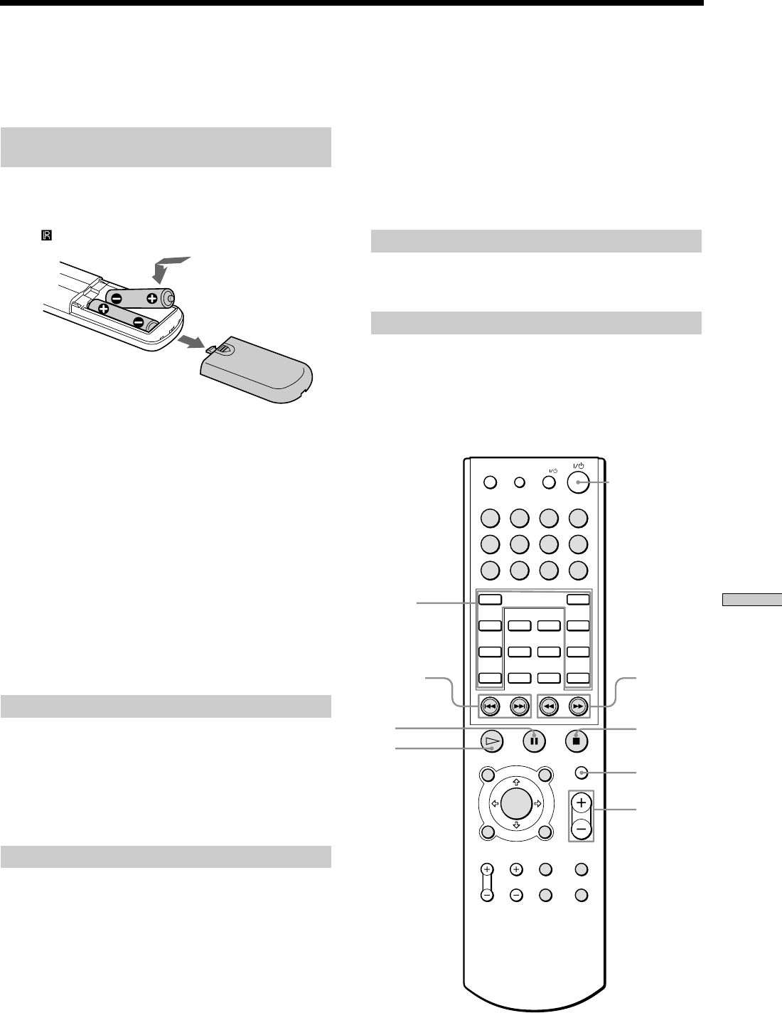
Using the RF Remote Control
Commands on the touch panel vary depending on the RF
Remote Control programming.
Turning the system on or off
1Press SYSTEM OFF.
“ALL OFF”, “MAIN OFF”, and “RETURN” appear on
the touch panel.
2Press “ALL OFF” when you want to turn off all
zones, and press “MAIN OFF” when you want to
turn off the main zone only.
Press “RETURN” when you want to cancel the
operation.
CHANNEL
POWER OFF
VOLUME
MUTING
MUTING SYSTEM OFF
Used for controlling
the source.
Used for controlling
the source.
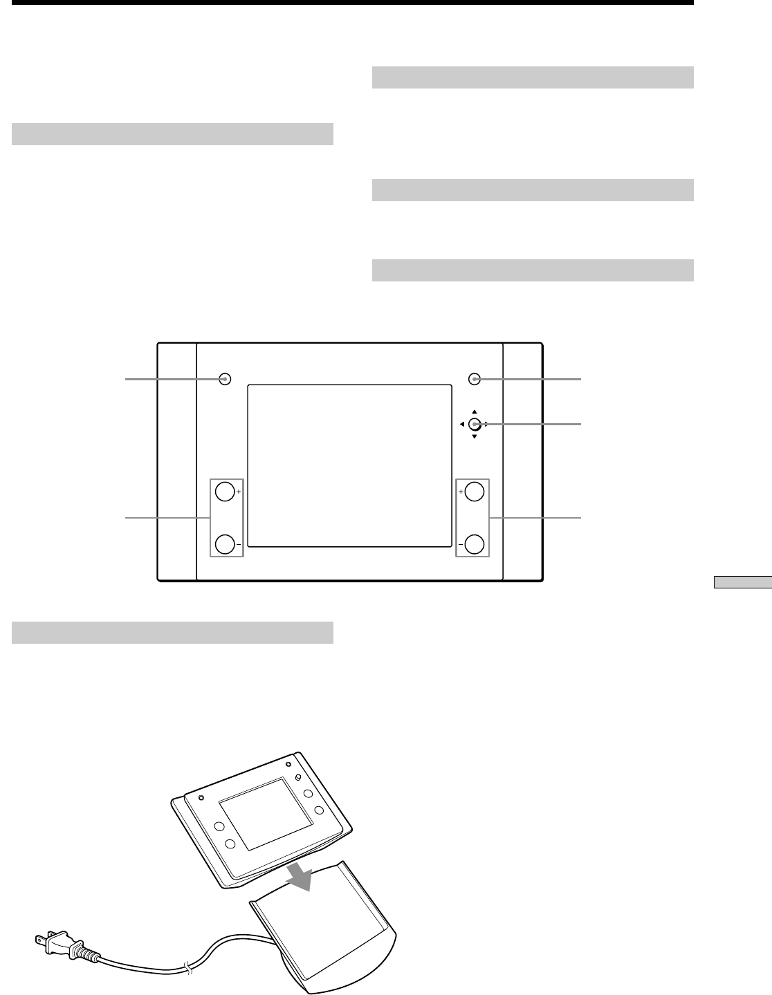
Charging the internal battery
1Connect the AC power cord of the charger cradle to
the wall outlet.
2Place the RF Remote Control on the charger cradle.
The internal battery starts charging.
Turning the RF Remote Control off
Leave the RF Remote Control alone for a few
minutes.
The RF Remote Control turns off automatically.
Adjusting the volume
Press VOLUME +/– to the desired volume level.
Muting the volume
Press MUTING.
To cancel the muting, press MUTING again.
VOLUME +/–
To the wall outlet
1
2
40
Appendix
PAGE SOURCE MUTING
VOLUME
POWER
Using the Keypad
Shows the selected source,
zone volume level, zone
and system status, and
other system status
information.
Press to select a menu on
the display on the LCD,
such as a source menu, disc
title list, tuner preset
station list, etc.
Press to scroll the LCD menu.
Press to mute the speaker
output from the Keypad.
Press to return to the home
screen, while the selected
source component is still
enabled.
Press to increase/decrease
the volume in a zone.
Press to turn the Keypad
on/off.
Turning the Keypad on or off
Press POWER to turn the Keypad on.
The source components also turn on.
To turn the Keypad off, press POWER again.
When the last zone is turned off, all the source
components also turn off.
Selecting and controlling the source
1Press SELECT next to the desired source displayed
in the LCD window.
The selected source is activated.
2Press any of the following buttons to control the
activated source component.
H: Operates the selected source component.
X: Pauses the playback.
x: Stops the playback.
./>: Locates a specific track or preset station.
Adjusting the volume
Press VOLUME +/– to the desired listening level.
Muting the volume
Press MUTING.
To cancel the muting, press MUTING again or VOLUME +.
Receives IR signals from the
IR Remote Control for Keypad
(supplied).
H: Press to operate the
selected source
component.
X: Press to pause playback.
x: Press to stop playback.
./>:Locates a specific
track or preset station.
Press to select a menu on the
display on the LCD, such as a
source menu, disc title list,
tuner preset station list, etc.
Press to return to the
previous menu or to view the
current status of the disc title
list or the preset station list.
If there is no list, only a
source name will be
displayed.
Press to lock the selected
source component.
41
Appendix
Using the IR Remote Control for the Keypad
1234
5678
90
>1 0
SLEEP DIMMER
ENTER
SELECT
LOCK DISC
PAGE SOURCE
DOWN
GUIDE
TOP MENU/ MENU MUTING
VOLUME
RETURN/EXITDISPLAY
TV VOL TV CH FOLDER F1
TV/VIDEO F2
UP
TV
Buttons marked in grey are used to control the source
components.
Inserting batteries into the Remote
Control
Insert two R06 (size-AA) batteries into the battery
compartment with the + and – correctly oriented to the
markings. When using the Remote, point it at the IR
sensor on the Keypad.
zWhen to replace the batteries
Under normal conditions, the batteries should last for about six
months. When the remote no longer operates the player, replace
both batteries with new ones.
Notes
•Do not leave the Remote Control in an extremely hot or a
humid place.
•Do not drop any foreign object into the Remote Control casing,
particularly when replacing the batteries.
•Do not use a new battery with an old one.
•Do not expose the IR sensor to direct sunlight or lighting
equipment. Doing so may cause a malfunction.
•If you do not intend to use the Remote Control for an extended
period of time, remove the batteries to avoid possible damage
from battery leakage and corrosion.
Turning the Keypad on or off
Press ?/1 to turn the Keypad on.
The source components also turn on.
To turn the Keypad off, press ?/1 again.
When the last active zone is turned off, all the source
components also turn off.
Selecting and controlling the source
1Press SELECT next to the desired source displayed
in the LCD window.
The selected source is activated.
2Press any of the following buttons to control the
activated source component.
H: Operates the selected source component.
X: Pauses playback.
x: Stops playback.
./>: Locates a specific track or preset station.
m/M: Locates a section you want to play within a
track.
Adjusting the volume
Press MASTER VOL +/– to the desired volume level.
Muting the volume
Press MUTING.
To cancel the muting, press MUTING again or VOLUME +.
m/M
x
MUTING
VOLUME
X
H
./>
SELECT

42
Appendix

43
Appendix

44
Información complementaria
Sony Corporation Printed in Malaysia