Sony Group SNCM3W Network Camera User Manual SNC M3 M3W
Sony Corporation Network Camera SNC M3 M3W
UserManual.wiki
>
Sony Group
>
SNCM3W User Manual
Manual revised
Navigation menu
Upload a User Manual
Namespaces
Wiki Guide
HTML
PDF
Info
Views
User Manual
Discussion / Help
Navigation
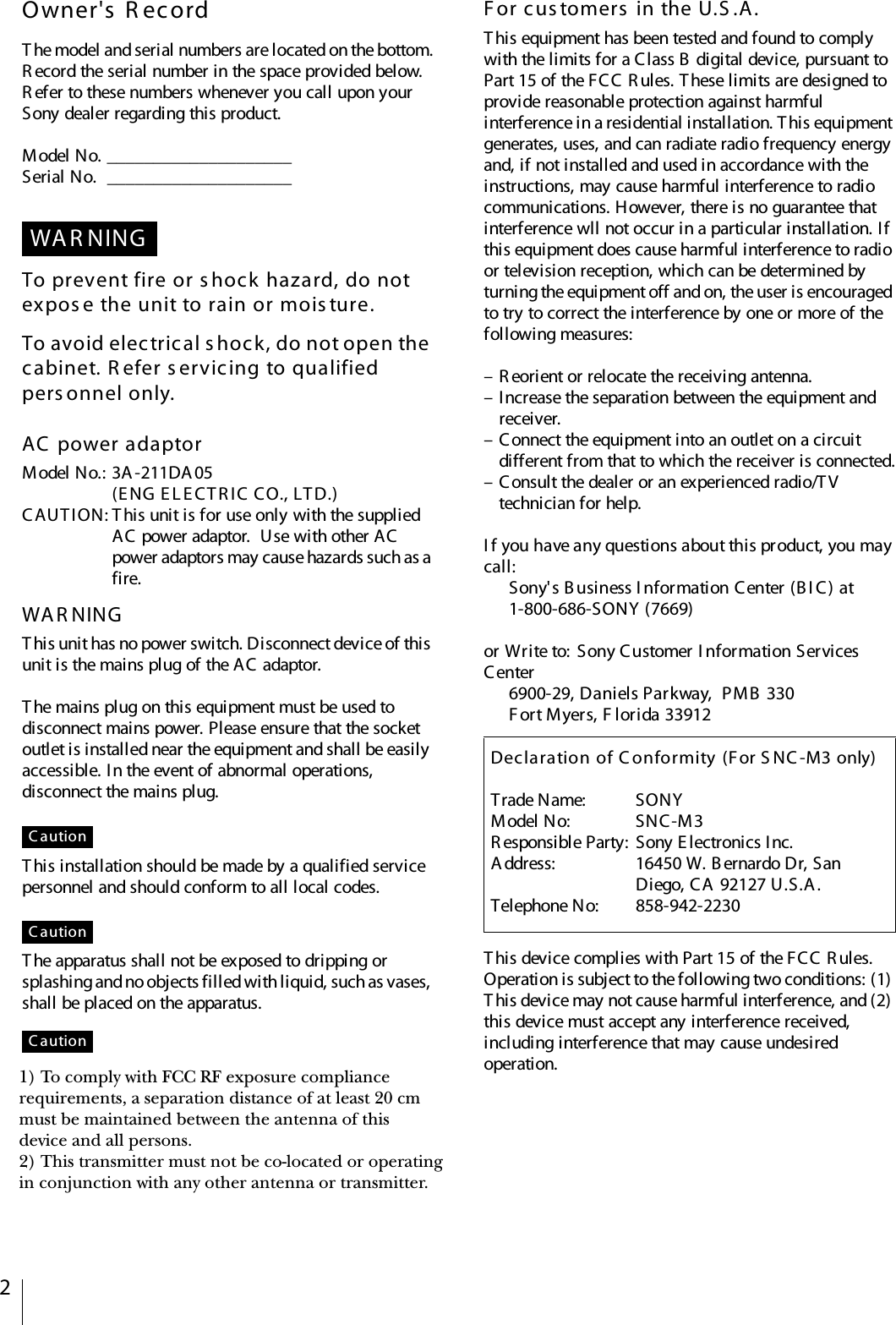

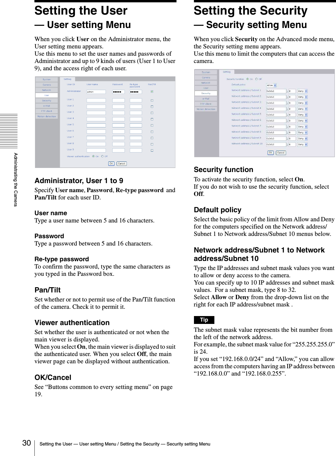
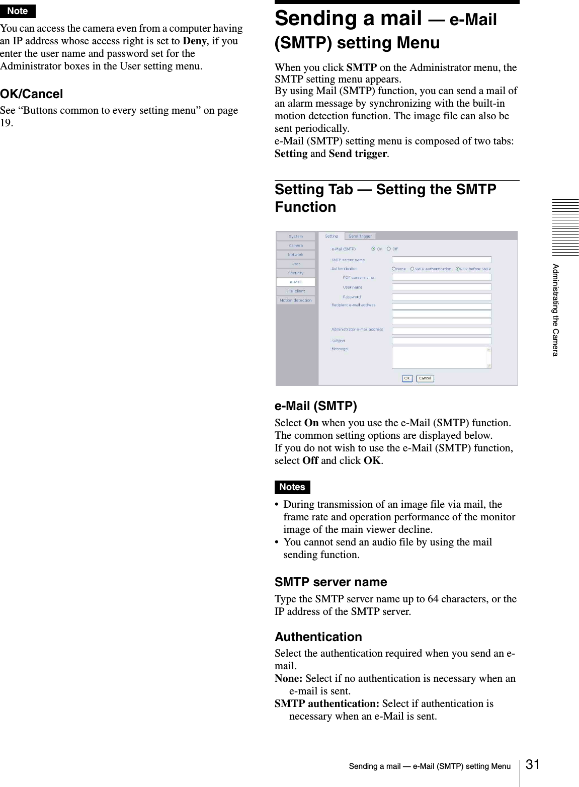
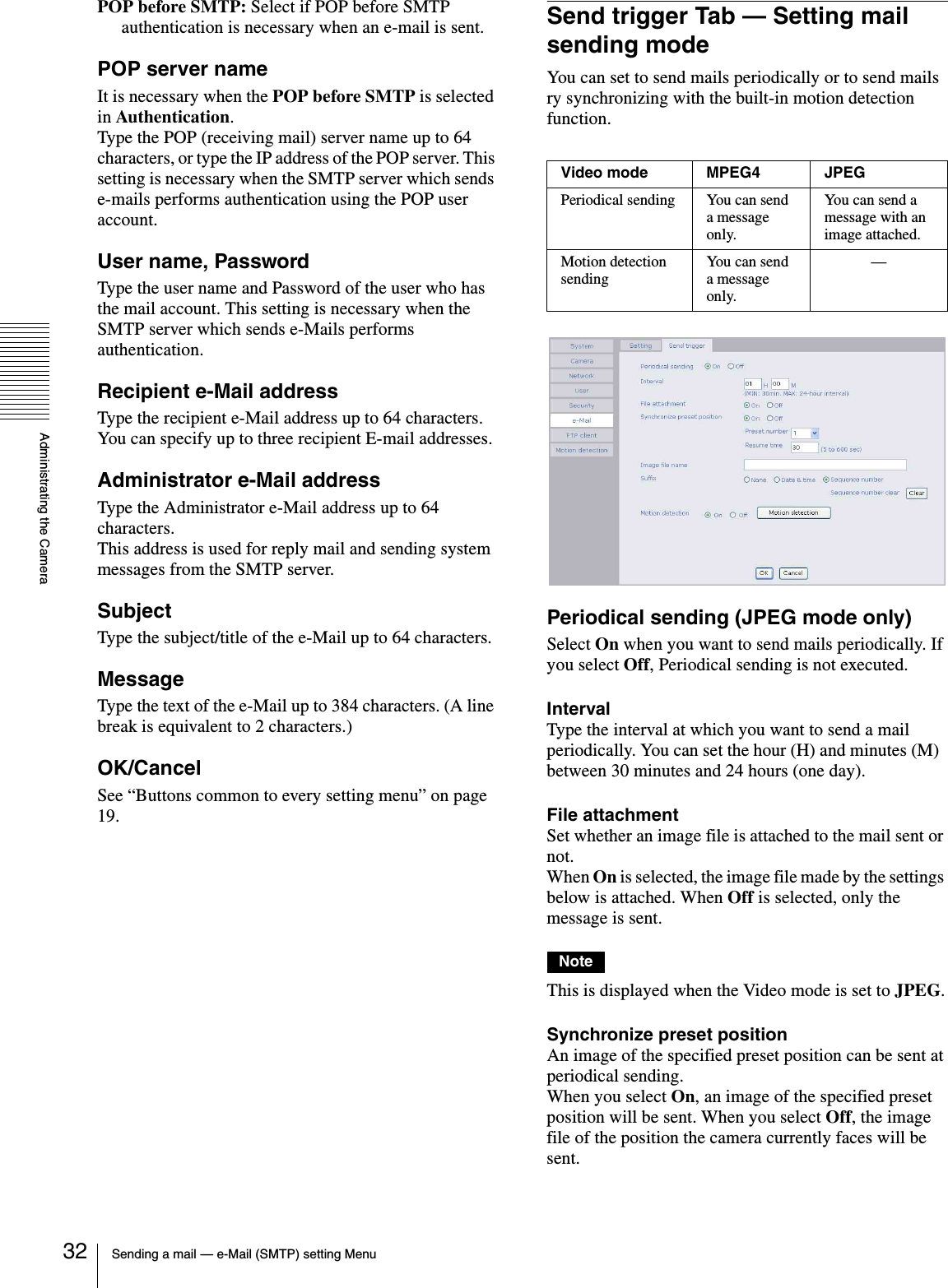
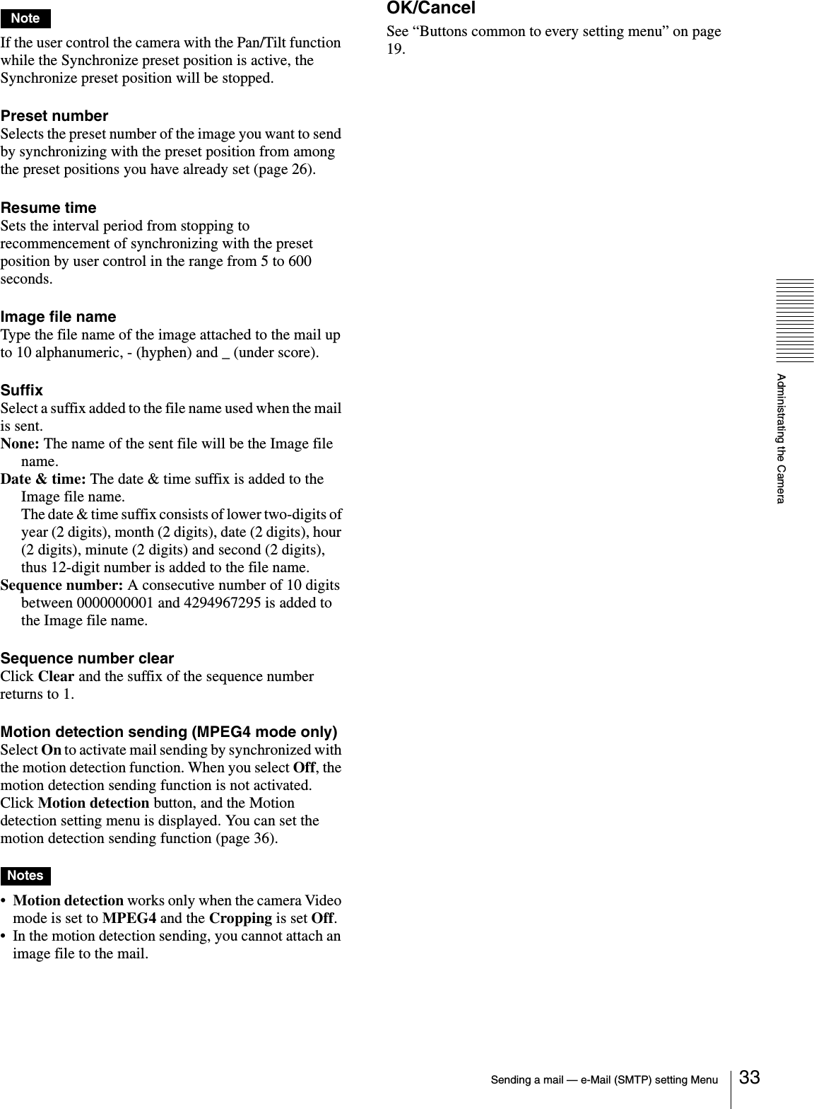
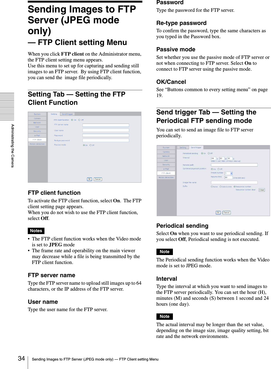
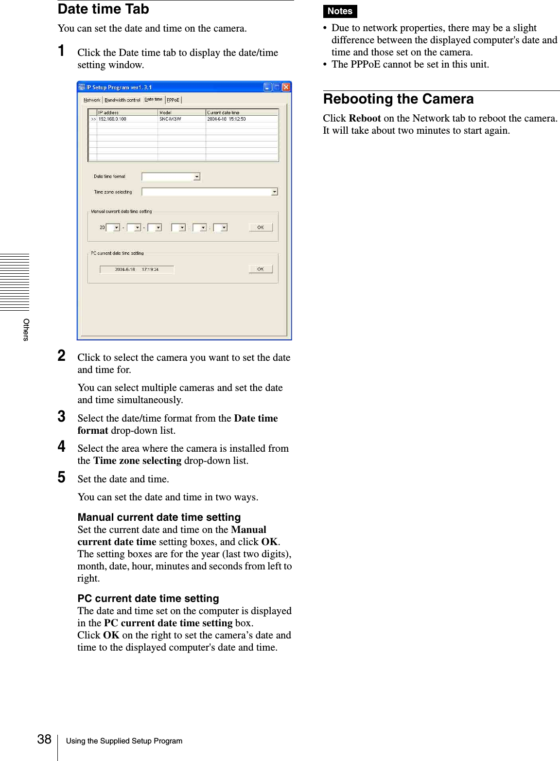
![Administrating the CameraConfiguring the Network — Network setting Menu 29POP server nameIt is necessary when the POP before SMTP is selected in Authentication.Type the POP (receiving mail) server name up to 64 characters. Or type the IP address of the POP server. This setting is necessary when the SMTP server which sends e-mails performs authentication using the POP user account.User name, PasswordType the user name and Password of the user who has the mail account. This setting is necessary when the SMTP server which sends e-Mails performs authentication.Recipient e-Mail addressType the recipient e-Mail address up to 64 characters. You can specify only one recipient e-Mail address.Administrator e-Mail addressType the e-Mail address of the camera administrator, up to 64 characters. This is used as the reply address or the address for a system mail from the mail server.SubjectType the subject/title of the e-Mail up to 64 characters.MessageType the text of the e-Mail up to 384 characters. You can describe the information of the acquired IP address, etc. using the special tags mentioned below.HTTP notificationSelect On to output a command to the HTTP server when the DHCP setting is completed. Using this function, you can configure a useful system, for example, to view the access log stored in the HTTP server or start an external CGI program.URLSpecify the URL to send HTTP commands, up to 256 characters. The URL is normally composed as follows:http://ip_address[:port]/path?parameterip_address: Type the IP address or host name of the host to which you want to connect.:port: Specify the port number to which you want to connect. If you want to use the well-known port number 80, you do not need to input this value.path: Type the command name.parameter: Type the command parameter if necessary. You can use the special tags mentioned below for the parameters.Proxy server nameWhen you send HTTP commands via a proxy server, type the name or IP address of the proxy server, up to 64 characters.Proxy port numberSpecify the port number when you send HTTP commands via the proxy server. Set a port number between 1024 and 65535.MethodSelect the HTTP method GET or POST.OK/CancelSee “Buttons common to every setting menu” on page 19.About the special tagsYou can use the following five special tags to allow the notification of the settings acquired by the DHCP, such as an IP address. Type the tags in the parameter section of the URL that you describe in the Message field of the HTTP.<IP>Use this tag to embed the IP address acquired by the DHCP in the text or parameter.<HTTPPORT>Use this tag to embed the specified HTTP server port number in the text or parameters.<MACADDRESS>Use this tag to embed the MAC address of the interface whose IP address you have acquired by the DHCP, in the text or parameter.<MODELNAME>Use this tag to embed the camera's model name (SNC-M3 or SNC-M3W) in the text or parameter.<SERIAL>Use this tag to embed the camera's serial number in the text or parameter.](https://usermanual.wiki/Sony-Group/SNCM3W/User-Guide-491787-Page-29.png)