Sony Group UTXB03 UHF SYNTHESIZED WIRELESS MICROPHONE User Manual UWP D11 D12 D16
Sony Corporation UHF SYNTHESIZED WIRELESS MICROPHONE UWP D11 D12 D16
Contents
Users manual

Wireless Microphone
Package
Operating Instructions
Before operating the unit, please read this manual thoroughly
and retain it for future reference.
UWP-D11/D12/D16
4-530-735-11 (1)
© 2014 Sony Corporation

Table of Contents
2
Table of Contents
Configuration of the Packages ..................3
UWP-D11 ..................................................... 3
UWP-D12 ..................................................... 4
UWP-D16 ..................................................... 5
Features .......................................................6
UWP-D11 ..................................................... 6
UWP-D12 ..................................................... 6
UWP-D16 ..................................................... 6
Name and Function of Parts.......................7
Body-pack transmitter (UTX-B03)............... 7
Hand-held microphone (UTX-M03)............. 8
Plug-on transmitter (UTX-P03).................. 10
Portable diversity tuner (URX-P03) ........... 11
Power Supply.............................................13
Inserting the batteries.................................. 13
Supplying power from a USB connector.... 14
Charging nickel metal hydride batteries..... 15
Attaching Accessories..............................15
Attaching accessories to the body-pack
transmitter (UTX-B03)...................... 15
Attaching accessories to the hand-held
microphone (UTX-M03) ................... 16
Attaching accessories to the plug-on
transmitter (UTX-P03) ...................... 16
Attaching accessories to the portable
diversity tuner (URX-P03) ................ 17
Operation ...................................................18
If noise is generated .................................... 18
Tuner Settings ...........................................19
Menu structure and operation ..................... 19
Setting the receive channel ......................... 20
Searching for available channels within a
group (Clear Channel Scan) .............. 20
Searching for active channels within a group
(Active Channel Scan) ...................... 21
Adjusting the monitor audio level .............. 21
Configuration menu.................................... 22
Transmitter Settings .................................24
Menu structure and operation ..................... 24
Setting the transmit channel........................ 25
Configuration menu.................................... 26
System Configuration Examples .............29
Error Messages .........................................30
Troubleshooting ........................................31
Important Notes on Use............................33
Usage and storage ....................................... 33
Cleaning...................................................... 33
Specifications............................................33
Transmitter (UTX-B03/M03/P03).............. 33
Tuner........................................................... 35
Configuration of the Packages 3
Configuration of the Packages
This manual is for the UWP-D11/D12/D16 Wireless Microphone Packages. The contents of each package are described
below.
Some of the packages may not be available in certain countries or areas.
For details, consult your Sony dealer.
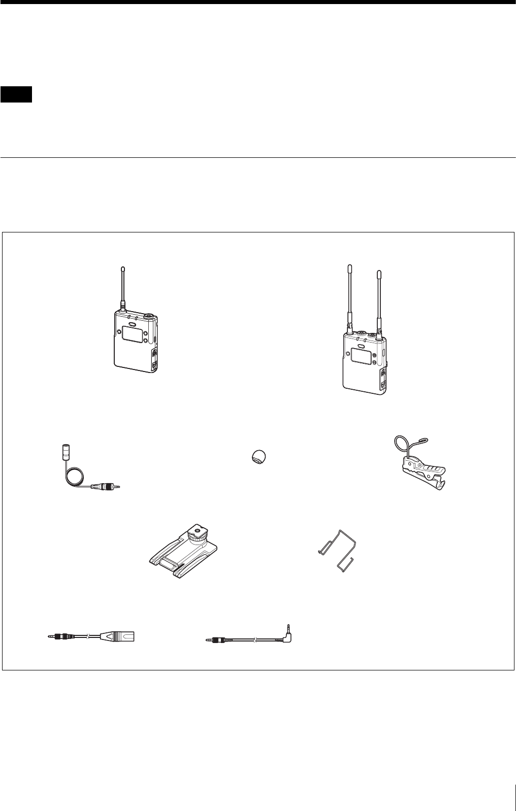
UWP-D11
The package consists of a body-pack transmitter (UTX-B03), a portable diversity tuner (URX-P03), and their accessories.
When used in conjunction with a compact camcorder, a mobile system for ENG (Electronic News Gathering) or EFP
(Electronic Field Production) applications can be constructed.
Note
Body-pack transmitter
(UTX-B03) (1)
Portable diversity tuner
(URX-P03) (1)
Supplied accessories
Wind screen (1)Omni-directional lavalier microphone (1) Holder clip (1)
Shoe mount adapter (1) Belt clip (2)
Battery case (1) (CN models only)
Before Use (1)
Quick Start Guide (1)
CD-ROM (1)
Warranty card (1)
(UC and KR models only)
Stereo mini plug-BMP conversion
cable (1)
XLR-BMP conversion output cable
for the URX-P03 (1)
Configuration of the Packages
4
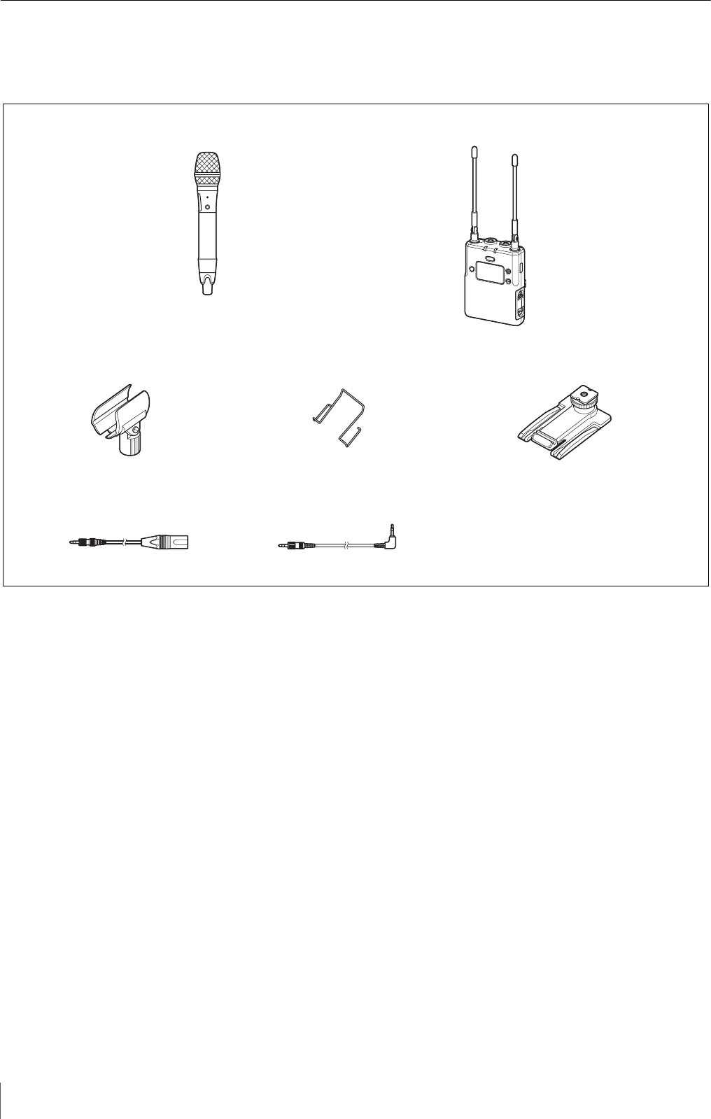
UWP-D12
The package consists of a hand-held microphone (UTX-M03), a portable diversity tuner (URX-P03), and their accessories.
When used in conjunction with a compact camcorder, a mobile system for ENG (Electronic News Gathering) or EFP
(Electronic Field Production) applications can be constructed.
Microphone holder (1)
XLR-BMP conversion output cable
for the URX-P03 (1)
Shoe mount adapter (1)Belt clip (1)
Battery case (1) (CN models only)
Before Use (1)
Quick Start Guide (1)
CD-ROM (1)
Warranty card (1)
(UC and KR models only)
Stereo mini plug-BMP conversion
cable (1)
Supplied accessories
Hand-held microphone
(UTX-M03) (1)
Portable diversity tuner
(URX-P03) (1)
Configuration of the Packages 5
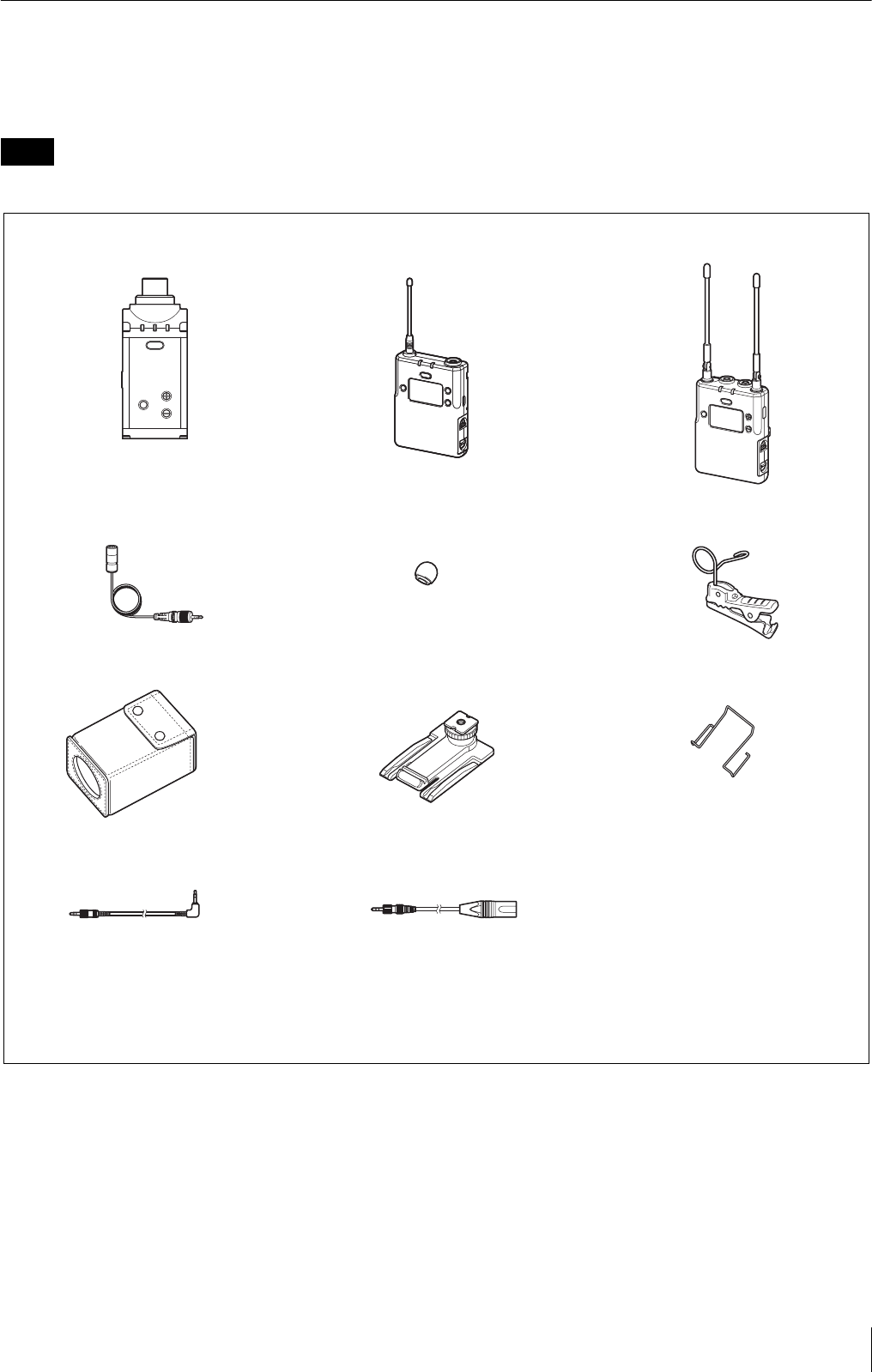
UWP-D16
The UWP-D16 consists of a plug-on transmitter (UTX-P03), a body-pack transmitter (UTX-B03), a portable diversity
tuner (URX-P03), and their accessories. When used in conjunction with a compact camcorder, a mobile system for ENG
(Electronic News Gathering) or EFP (Electronic Field Production) applications can be constructed.
The CN model of this package is not available.
Note
Body-pack transmitter
(UTX-B03) (1)
Portable diversity tuner
(URX-P03) (1)
Supplied accessories
Soft case (1)
Plug-on transmitter
(UTX-P03) (1)
Shoe mount adapter (1) Belt clip (2)
Wind screen (1) Holder clip (1)
Stereo mini plug-BMP
conversion cable (1) XLR-BMP conversion output cable for the
URX-P03 (1)
Omni-directional lavalier microphone (1)
Battery case (1) (CN models only)
Before Use (1)
Quick Start Guide (1)
CD-ROM (1)
Warranty card (1) (UC and KR models only)

Features
6
Features
The UWP-D11/D12/D16 (UWP series) Wireless
Microphone Packages comprise a transmitter (body-pack
transmitter (UTX-B03), hand-held microphone
(UTX-M03), or plug-on transmitter (UTX-P03)) and a
receiver (portable diversity tuner (URX-P03)). They can
be used for ENG (Electronic News Gathering) in
combination with a miniature camcorder.
They are equipped with a DSP for transmission of high-
quality sound using digital compander processing. They
can be used in combination with current Sony wireless
microphone systems (UWP series, WRT series, WRR
series, WRU series) by switching the compander mode.
The frequency and compander mode set on the tuner can
be sent to the transmitter using an infrared
communications link. Used in combination with the Clear
Channel Scan function of the tuner, this greatly reduces
the time required to set channels.
The contents of each package are described below.
UWP-D11
Body-pack transmitter (UTX-B03)
This transmitter is a lightweight, compact transmitter that
employs a crystal-controlled PLL synthesizer. It is
equipped with a muting function and a BMP-type
microphone input connector. The RF power output can be
switched between high and low. It is also equipped with a
MIC/LINE input switching function to support a variety
of input levels.
Portable diversity tuner (URX-P03)
This tuner employs a space diversity method featuring
little signal dropout and an angle-adjustable antenna. It
comes with an adapter for mounting on a compact
camcorder (HXR-NX3, etc.). It also features a Clear
Channel Scan function to search for available channels
automatically.
UWP-D12
Hand-held microphone (UTX-M03)
This microphone features a robust, metallic body. It has a
muting function and attenuator adjustment function to
support a wide audio input level range.
It can be used in diverse applications simply by changing
the microphone capsule. It has a built-in antenna.
* Microphone unit mounting dimensions: 31.3 mm
diameter, 1.0 mm pitch
Portable diversity tuner (URX-P03)
This tuner employs a space diversity method featuring
little signal dropout and an angle-adjustable antenna. It
comes with an adapter for mounting on a compact
camcorder (HXR-NX3, etc.). It also features a Clear
Channel Scan function to search for available channels
automatically.
UWP-D16
Plug-on transmitter (UTX-P03)
This transmitter is a lightweight, compact plug-on type
transmitter that employs a crystal-controlled PLL
synthesizer. It has a muting function and an XLR-type
microphone input connector that can supply +48 V power
for connecting a wide range of microphones. It is also
equipped with a MIC/LINE switching function to support
a variety of input levels.
Body-pack transmitter (UTX-B03)
This transmitter is a lightweight, compact transmitter that
employs a crystal-controlled PLL synthesizer. It is
equipped with a muting function and a BMP-type
microphone input connector. The RF power output can be
switched between high and low. It is also equipped with a
MIC/LINE input switching function to support a variety
of input levels.
Portable diversity tuner (URX-P03)
This tuner employs a space diversity method featuring
little signal dropout and an angle-adjustable antenna. It
comes with an adapter for mounting on a compact
camcorder (HXR-NX3, etc.). It also features a Clear
Channel Scan function to search for available channels
automatically.
Name and Function of Parts 7
Name and Function of
Parts
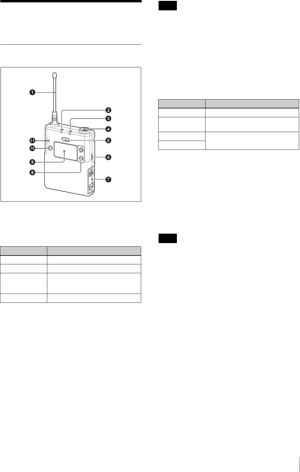
Body-pack transmitter (UTX-B03)
aAntenna
bPOWER indicator
Displays the battery level and charging status.
cAUDIO (audio input level) indicator
Turns on or off according to the audio input level as
follows.
On (red): Audio input level is too high. If the sound is
distorted, adjust the attenuation level to decrease the
audio input level (page 26).
On (green): Audio input level is appropriate.
Off: There is no audio input or the input level is too low.
Flashing (orange): Audio is muted (i.e., disabled).
dAudio input connector (BMP type)
Connect to the supplied lavalier microphone.
• When the audio input level is set to MIC, a voltage for
the lavalier microphone power supply is applied to the
audio input connector. Special electrical wiring is used
inside the audio input connector for this purpose.
• If a lavalier microphone other than the one supplied is
connected, the proper performance may not be
obtained.
ePOWER/MUTING button
Turns the power on/off. You also use this button to turn
the muting function on/off.
fUSB connector (Micro B type)
Connect to a commercially available USB portable power
supply.
When a USB portable power supply is connected while
the power is turned on, the unit automatically operates
with power supplied by the USB portable power supply.
When a USB portable power supply is connected while
nickel metal hydride batteries are inserted and the power
is turned off, the batteries are charged by the USB
portable power supply.
Alkaline batteries and lithium batteries cannot be
recharged.
gBattery compartment
Accepts two AA batteries (alkaline, nickel metal hydride,
or lithium batteries).
For details on how to insert batteries, see “Power
Supply” (page 13).
h+ or – button
Selects functions or values shown on the display.
Indicator display Status
On (green) Sufficient battery level
Flashing (green) Battery is getting low
On (orange) Charging (when nickel metal hydride
rechargeable batteries are inserted
and power is turned off)
Off Power is off or battery is empty
Notes
Function Operation
Supply ON Press button for one second or longer
Supply OFF Press button until the indicator turns
off
Muting ON Press button
Muting OFF
Note
Name and Function of Parts
8
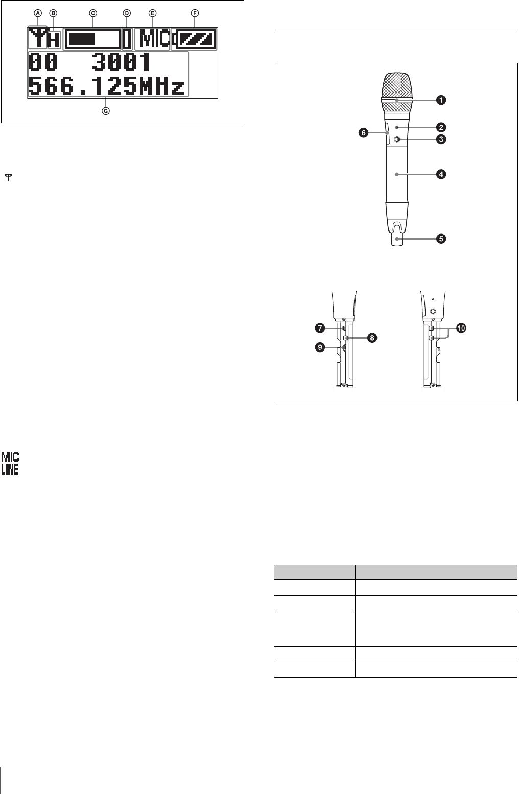
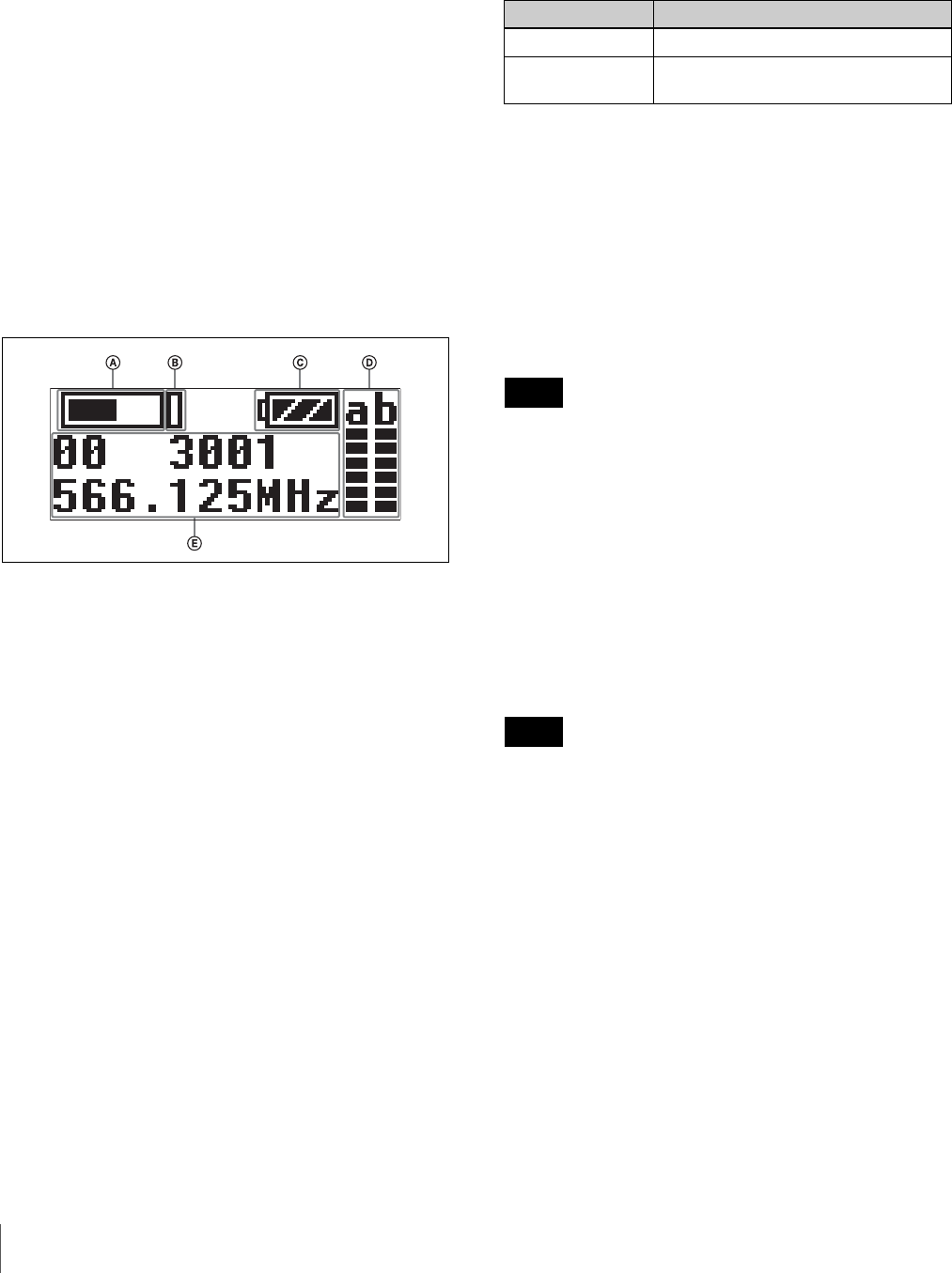
iDisplay section
ARF transmission indicator
Displays the current transmission status.
BRF transmission power indicator
Indicates the current transmission power setting. You can
change the setting with the RF transmission power setting
function.
For details on the RF transmission power setting
function, see “Setting the transmit output level (RF
POWER)” (page 26).
CAudio input level meter
Displays the the audio input level.
DPeak indicator
Lights up when the signal is 3 dB below the level at which
distortion begins as a warning of excessive input level.
EInput level indicator
Displays the input level status.
: Microphone input
: Line input
FBattery level indicator
Displays the battery level. Displays “EXT” when power
is supplied from the USB connector.
For details, see “Battery level indicator” (page 14).
GMenu display section
Displays various functions. Press the + or – button to
switch functions.
For details, see “Configuration menu” (page 22).
jSET button
Adjusts displayed function settings and enters the
displayed value.
Holding down the SET button while turning on the power
turns the transmitter on without transmitting a signal
(transmission stopped mode).
kInfrared detector
Receives the frequency and compander mode set on the
tuner.
Hand-held microphone (UTX-M03)
aMicrophone unit
The standard-equipped microphone unit can be
interchanged with another microphone unit having a
diameter of 31.3 mm and a pitch of 1.0 mm.
For details on attaching and removing the microphone
unit, see “Replacing the microphone unit” (page 16).
bPOWER indicator
Displays the battery level, charging status, and audio
muting (i.e., audio enabled or disabled) status.
: Transmitting
– : Transmission stopped
Indicator display Status
On (green) Sufficient battery level
Flashing (green) Battery is getting low
On (orange) Charging (when nickel metal hydride
rechargeable batteries are inserted
and power is turned off)
Off Power is off or battery is empty
Flashing (orange) Audio is muted (i.e., disabled)
Inside the grip
Name and Function of Parts 9
cPOWER/MUTING button
Turns the power on/off. You also use this button to turn
the muting function on/off.
dBattery compartment
Accepts two AA batteries (alkaline, nickel metal hydride,
or lithium batteries).
For details on how to insert batteries, see “Power
Supply” (page 13).
eAntenna section
fDisplay section
ARF transmission indicator
Displays the current transmission status.
BRF transmission power indicator
Indicates the current transmission power setting. You can
change the setting with the RF transmission power setting
function.
For details on the RF transmission power setting
function, see “Setting the transmit output level (RF
POWER)” (page 26).
CAudio input level meter
Displays the the audio input level.
DPeak indicator
Lights up when the signal is 3 dB below the level at which
distortion begins as a warning of excessive input level.
EBattery level indicator
Displays the battery level.
For details, see “Battery level indicator” (page 14).
FMenu display section
Displays various functions. Press the + or – button to
switch functions.
For details, see “Configuration menu” (page 22).
gInfrared detector
Receives the frequency and compander mode set on the
tuner.
hSET button
Adjusts displayed function settings and enters the
displayed value.
Holding down the SET button while turning on the power
turns the transmitter on without transmitting a signal
(transmission stopped mode).
iUSB connector (Micro B type)
Connect to a commercially available USB portable power
supply.
When a USB portable power supply is connected while
nickel metal hydride batteries are inserted and the power
is turned off, the batteries are charged by the USB
portable power supply.
Alkaline batteries and lithium batteries cannot be
recharged. Also, power cannot be supplied from a USB
portable power supply.
j+ or – button
Selects functions or values shown on the display.
Function Operation
Supply ON Press button for one second or longer
Supply OFF Press button until the indicator turns
off
Muting ON Press button
Muting OFF
: Transmitting
– : Transmission stopped
Note
Name and Function of Parts
10
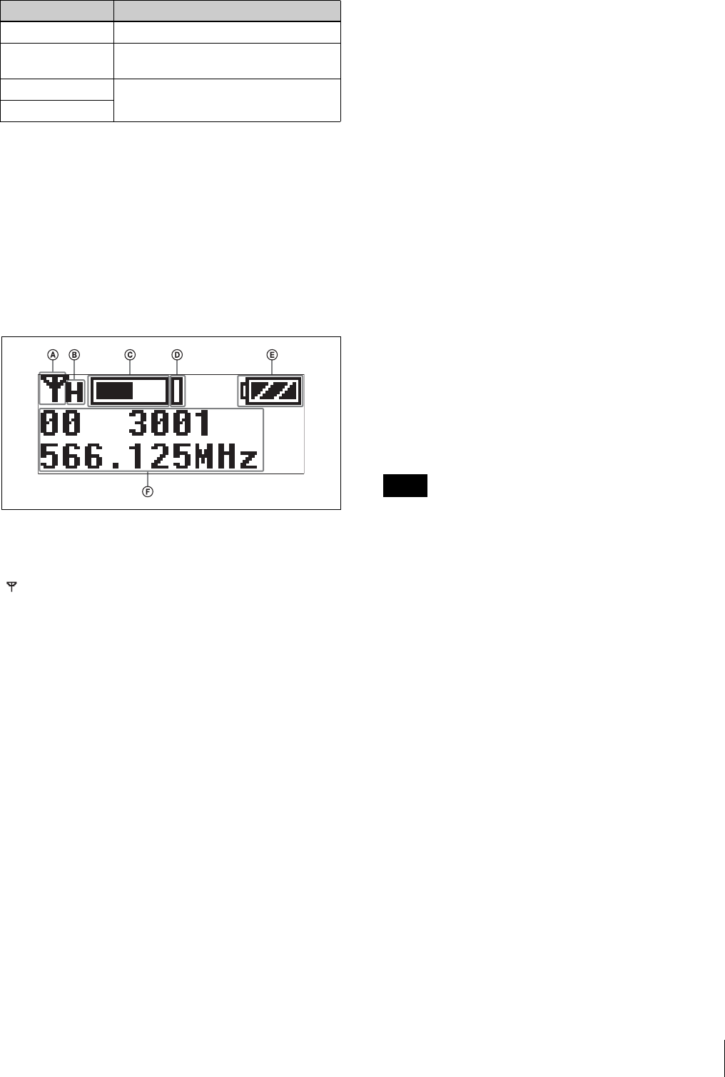
Plug-on transmitter (UTX-P03)
aAudio input connector (XLR type)
Connect to a microphone or the line output of an audio
mixer or other device.
b+48V (+48 V supply) indicator
Lights up when the unit is set to LINE input and is
supplying power to the connected microphone.
cPOWER indicator
Displays the battery level and charging status.
dAUDIO (audio input level) indicator
Turns on or off according to the audio input level as
follows.
On (red): Audio input level is too high. If the sound is
distorted, adjust the attenuation level to decrease the
audio input level (page 26).
On (green): Audio input level is appropriate.
Off: There is no audio input or input level is too low.
Flashing (orange): Audio is muted (i.e., disabled).
ePOWER/MUTING button
Turns the power on/off. You also use this button to turn
the muting function on/off.
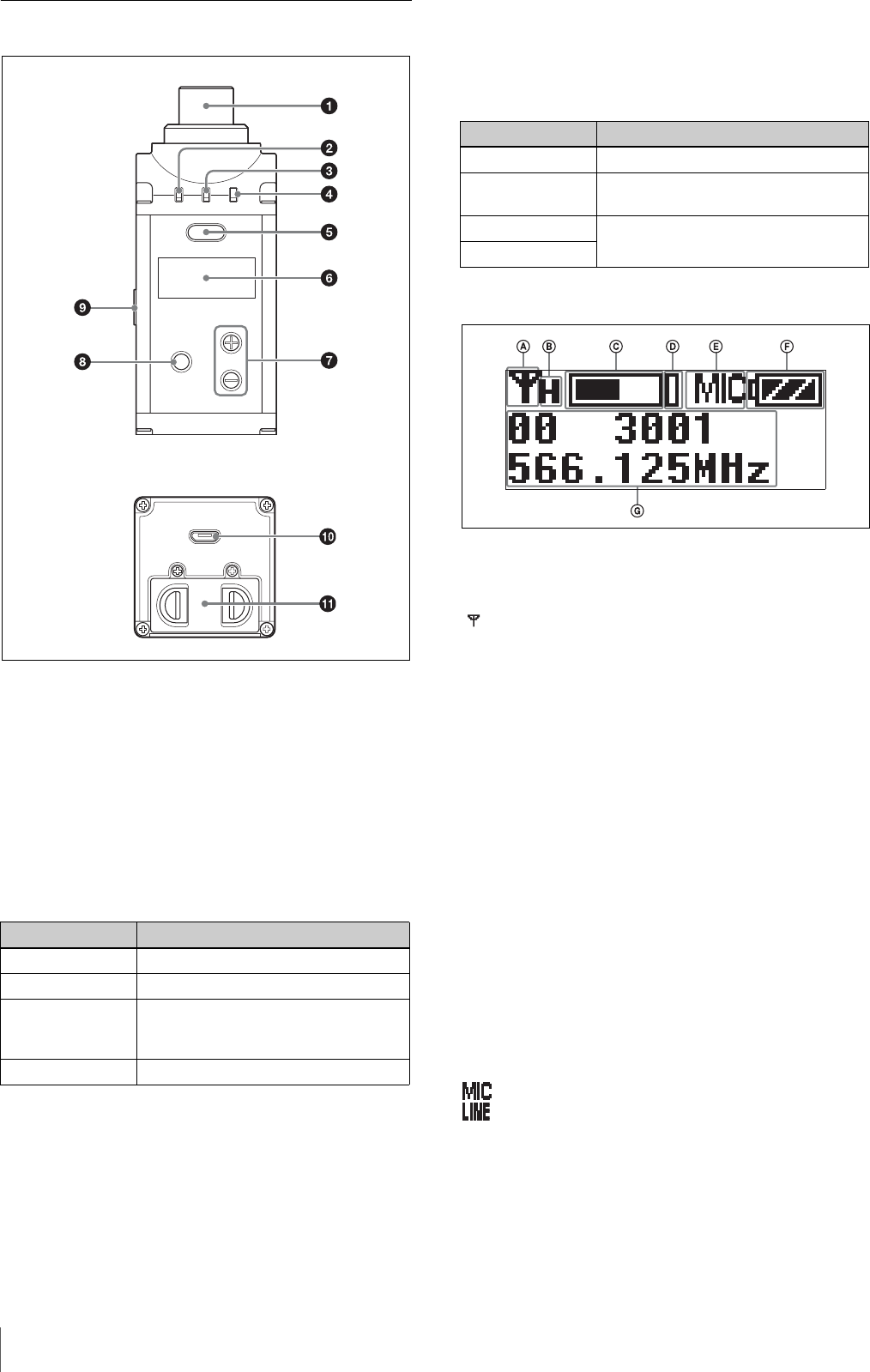
fDisplay section
ARF transmission indicator
Displays the current transmission status.
BRF transmission power indicator
Indicates the current transmission power setting. You can
change the setting with the RF transmission power setting
function.
For details on the RF transmission power setting
function, see “Setting the transmit output level (RF
POWER)” (page 26).
CAudio input level meter
Displays the the audio input level.
DPeak indicator
Lights up when the signal is 3 dB below the level at which
distortion begins as a warning of excessive input level.
EInput level indicator
Displays the input level status.
: Microphone input
: Line input
FBattery level indicator
Displays the battery level. Displays “EXT” when power
is supplied from the USB connector.
For details, see “Battery level indicator” (page 14).
Indicator display Status
On (green) Sufficient battery level
Flashing (green) Battery is getting low
On (orange) Charging (when nickel metal hydride
rechargeable batteries are inserted
and power is turned off)
Off Power is off or battery is empty
Front
Bottom
Function Operation
Supply ON Press button for one second or longer
Supply OFF Press button until the indicator turns
off
Muting ON Press button
Muting OFF
: Transmitting
– : Transmission stopped
Name and Function of Parts 11
GMenu display section
Displays various functions. Press the + or – button to
switch functions.
For details, see “Configuration menu” (page 22).
g+ or – button
Selects functions or values shown on the display.
hSET button
Adjusts displayed function settings and enters the
displayed value.
Holding down the SET button while turning on the power
turns the transmitter on without sending a signal
(transmission stopped mode).
iInfrared detector
Receives the frequency and compander mode set on the
tuner.
jUSB connector (Micro B type)
Connect to a commercially available USB portable power
supply.
When a USB portable power supply is connected while
the power is turned on, the unit automatically operates
with power supplied by the USB portable power supply.
When a USB portable power supply is connected while
nickel metal hydride batteries are inserted and the power
is turned off, the batteries are charged by the USB
portable power supply.
Alkaline batteries and lithium batteries cannot be
recharged.
kBattery compartment
Accepts two AA batteries (alkaline, nickel metal hydride,
or lithium batteries).
For details on how to insert batteries, see “Power
Supply” (page 13).
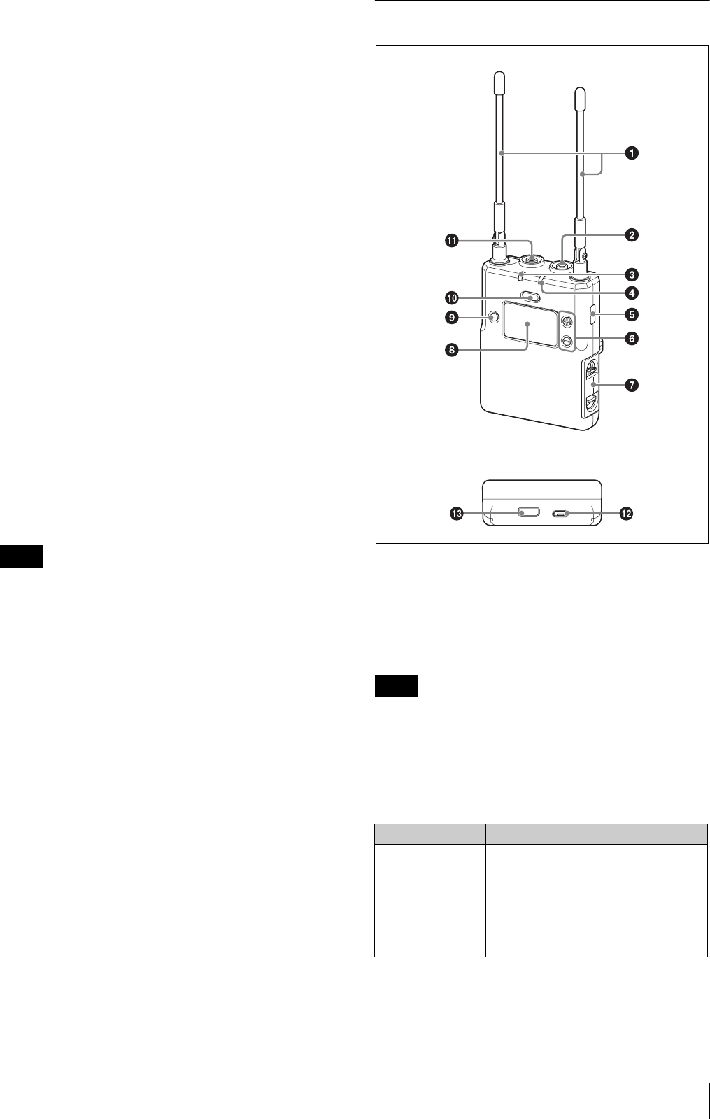
Portable diversity tuner (URX-P03)
aAntenna
bPHONES (monitor) connector (3.5-mm
diameter, stereo mini jack)
Connect to headphones to monitor the audio output.
Do not connect headphones with a monaural mini jack.
This may short-circuit the headphone outputs, resulting in
distorted sound output.
cPOWER indicator
Displays the battery level and charging status.
Note
Note
Indicator display Status
On (green) Sufficient battery level
Flashing (green) Battery is getting low
On (orange) Charging (when nickel metal hydride
rechargeable batteries are inserted
and power is turned off)
Off Power is off or battery is empty
Front
Bottom
Name and Function of Parts
12
dRF (radio frequency input) indicator
Displays the RF input level using the following colors.
On (green): Input level is 25 dBμ or more.
On (red): Input level is 15 to 25 dBμ.
Off: Input level is 15 dBμ or lower.
*0 dBμ = 1 μVEMF
eInfrared transmitter port
Sends the set frequency and compander mode to the
transmitter.
f+ or – button
Selects functions or values shown on the display.
gBattery compartment
Accepts two AA batteries (alkaline, nickel metal hydride,
or lithium batteries).
For details on how to insert batteries, see “Power
Supply” (page 13).
hDisplay section
AAudio input level meter
Displays the the audio input level.
BPeak indicator
Lights up when the signal is 3 dB below the level at which
distortion begins as a warning of excessive input level.
CBattery level indicator
Displays the battery level. Displays “EXT” when power
is supplied from the USB connector.
For details, see “Battery level indicator” (page 14).
DRF level (reception level) indicator
Indicates the current reception level.
EMenu display section
Displays various functions. Press the + or – button to
switch functions.
For details, see “Configuration menu” (page 22).
iSET button
Adjusts displayed function settings and enters the
displayed value.
Holding down the SET button while turning on the power
turns the transmitter on without sending a signal
(transmission stopped mode).
jPOWER button
Turns the power on/off.
kOUTPUT (audio output) connector (3.5-mm
diameter, stereo mini jack)
Connect one end of the supplied XLR-BMP conversion
output cable for the URX-P03 or the stereo mini plug-
BMP conversion cable here and the other end to the
microphone input on a camcorder, mixer, or amplifier. If
the microphone input connector on the connected device
is a stereo mini jack, connect the straight (BMP) plug to
the tuner and the L-shaped (stereo mini) plug to the
microphone input connector on the device.
To prevent damaging the tuner, do not apply a voltage to
this connector from a microphone external power supply
or other source.
lUSB connector (Micro B type)
Connect to a commercially available USB portable power
supply.
When the power is turned on, the unit operates with
power supplied by the USB portable power supply. When
nickel metal hydride batteries are inserted and the power
is turned off, the battery is charged by the USB portable
power supply.
Alkaline batteries and lithium batteries cannot be
recharged.
mAuxiliary connector
Used to connect external accessories.
Function Operation
Supply ON Press button for one second or longer
Supply OFF Press button until the indicator turns
off
Note
Note
Power Supply 13
Power Supply
This section describes the power supply of each device
and the charging of nickel metal hydride batteries.
Body-pack transmitter (UTX-B03) and plug-on
transmitter (UTX-P03)
The unit operates using power supplied from two AA
batteries (alkaline, nickel metal hydride, or lithium
batteries) or from a supply connected to the USB
connector. If power is supplied simultaneously from
batteries and from a supply connected to the USB
connector, power from the USB connector has
precedence. For details about inserting batteries in each
device and displaying the battery level, or supplying
power from a supply connected to the USB connector, see
the following sections.
Hand-held microphone (UTX-M03)
The unit operates from two AA batteries (alkaline, nickel
metal hydride, or lithium batteries). For details about
inserting batteries and displaying the battery level, see the
following sections.
Portable diversity tuner (URX-P03)
The unit operates from two AA batteries (alkaline, nickel
metal hydride, or lithium batteries), power supplied from
a supply connected to the USB connector, or power
supplied from the auxiliary connector. The power supply
that has precedence when both AA battery power and an
external power supply via the USB connector or auxiliary
connector are available can be specified using the
POWER SEL (external power selection) function. Under
the factory default setting, the power supplied from
inserted AA batteries has precedence. For details about
inserting batteries and displaying the battery level, or
supplying power from supply connected to the USB
connector, see the following sections.
For details on the POWER SEL function setting, see
“Selecting the preferred power supply (POWER SEL)”
(page 23).
The use of manganese batteries will result in poor
performance. Do not use manganese batteries.
Inserting the batteries
• Always use sets of the same type of battery. Do not use
batteries of different types or batteries with different
charge level together.
• Replacing the batteries during operation may generate
a large noise. Be sure to turn off the unit before
replacing the batteries.
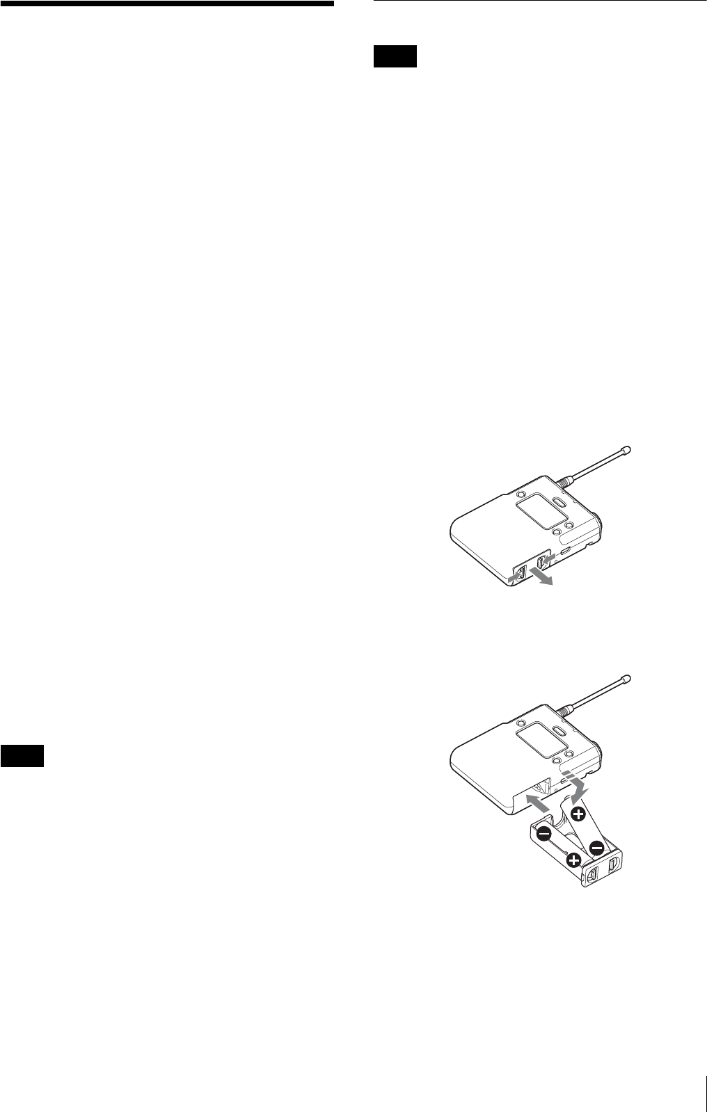
Body-pack transmitter (UTX-B03) / plug-
on transmitter (UTX-P03) / portable
diversity tuner (URX-P03)
The following describes the procedure using illustrations
for the body-pack transmitter (UTX-B03). Batteries can
be inserted in the plug-on transmitter (UTX-P03) and
portable diversity tuner (URX-P03) in the same manner.
1
Press and hold the POWER/MUTING button to turn
the power off.
2
Slide the two catches inward (as indicated) and pull
the battery compartment out.
3
Insert two new AA batteries into the battery
compartment with 3 and # polarities in the correct
orientation, and close the the compartment.
Make sure that the battery compartment is locked
securely.
Note
Notes
Power Supply
14
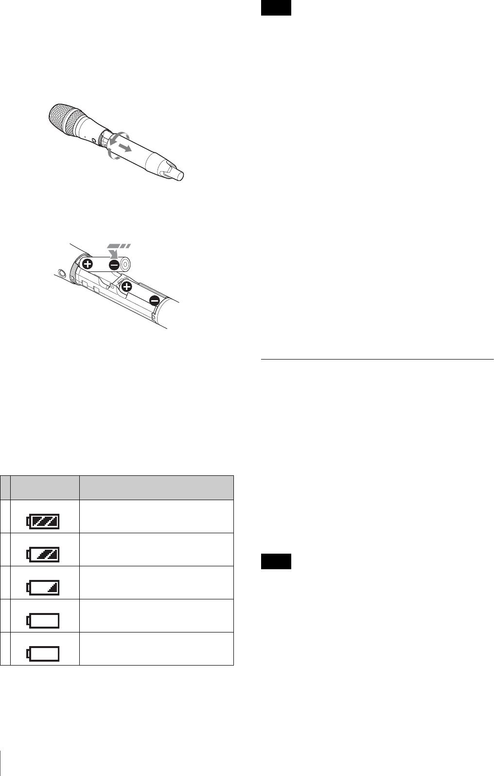
Hand-held microphone (UTX-M03)
1
Press and hold the POWER/MUTING button to turn
the power off.
2
Turn the grip in the direction of the arrow, and pull
the grip down until the battery compartment is
visible.
3
Insert two new AA batteries into the battery
compartment with 3 and # polarities in the correct
orientation.
4
Close the grip, turning it in the reverse direction of
step 2.
Battery level indicator
Press and hold the POWER button for 1 second or longer
to display the battery level on the display.
Immediately replace both batteries with new batteries if
the indicator starts flashing (indication 5 below). If using
new alkaline batteries, use after checking the
recommended time limits.
• When BATTERY is set to TYPE1, the battery level is
indicated based on the use of new LR6 (size AA) Sony
alkaline batteries. The battery level may not be
displayed correctly when different kinds of batteries,
different brand of batteries, or old batteries are used. If
using batteries other than size AA alkaline batteries,
select the battery type using the BATTERY function.
• If you plan to use the transmitter continuously for a long
period of time, it is recommended that you replace the
batteries with brand new ones.
For details on the BATTERY function setting, see “Setting
the battery type (BATTERY)” (page 23).
Battery precautions
Batteries may leak or explode if mistreated. Be sure to
follow these instructions.
• Insert batteries in the correct 3 and # polarity
orientation.
• Always replace the two batteries together with new
ones.
• Do not use different types of batteries or old and new
ones together.
• Dry cells are not rechargeable.
• When not using the device for a long period of time,
remove the batteries. If the batteries leak for any reason,
consult your Sony service representative.
Supplying power from a USB
connector
The transmitter (UTX-B03/P03) and tuner (URX-P03)
can operate from a commercially available portable
power supply (with USB output function) connected to
the USB connector.
Use a portable power supply that satisfies the following
conditions.
• Output connector: USB micro B type
• Rated voltage: 5 V
• Output current: 200 mA or higher
Displays “EXT” when power is supplied from the USB
connector.
The UTX-M03 hand-held microphone cannot be supplied
using a USB connector.
Battery level
indicator
Battery status
1Lights Good
2 Lights Less than 70% charge remaining
3 Lights Less than 40% charge remaining
4 Lights Less than 20% charge remaining
5 Flashes Almost empty
Notes
Note
Attaching Accessories 15
Charging nickel metal hydride
batteries
You can charge nickel metal hydride batteries inserted in
the transmitter (UTX-B03/M03/P03) and tuner
(URX-P03).
When charging nickel metal hydride batteries, turn the
power off and connect a commercially available portable
power supply (with USB output function) to the USB
connector.
The POWER indicator is lit orange while charging
batteries. When charging is finished, the POWER
indicator goes off.
Attaching Accessories
This section describes how to attach the supplied
accessories to each device.
Attaching accessories to the body-
pack transmitter (UTX-B03)
Connecting the microphone
Be sure to attach or remove the microphone after turning
off the transmitter.
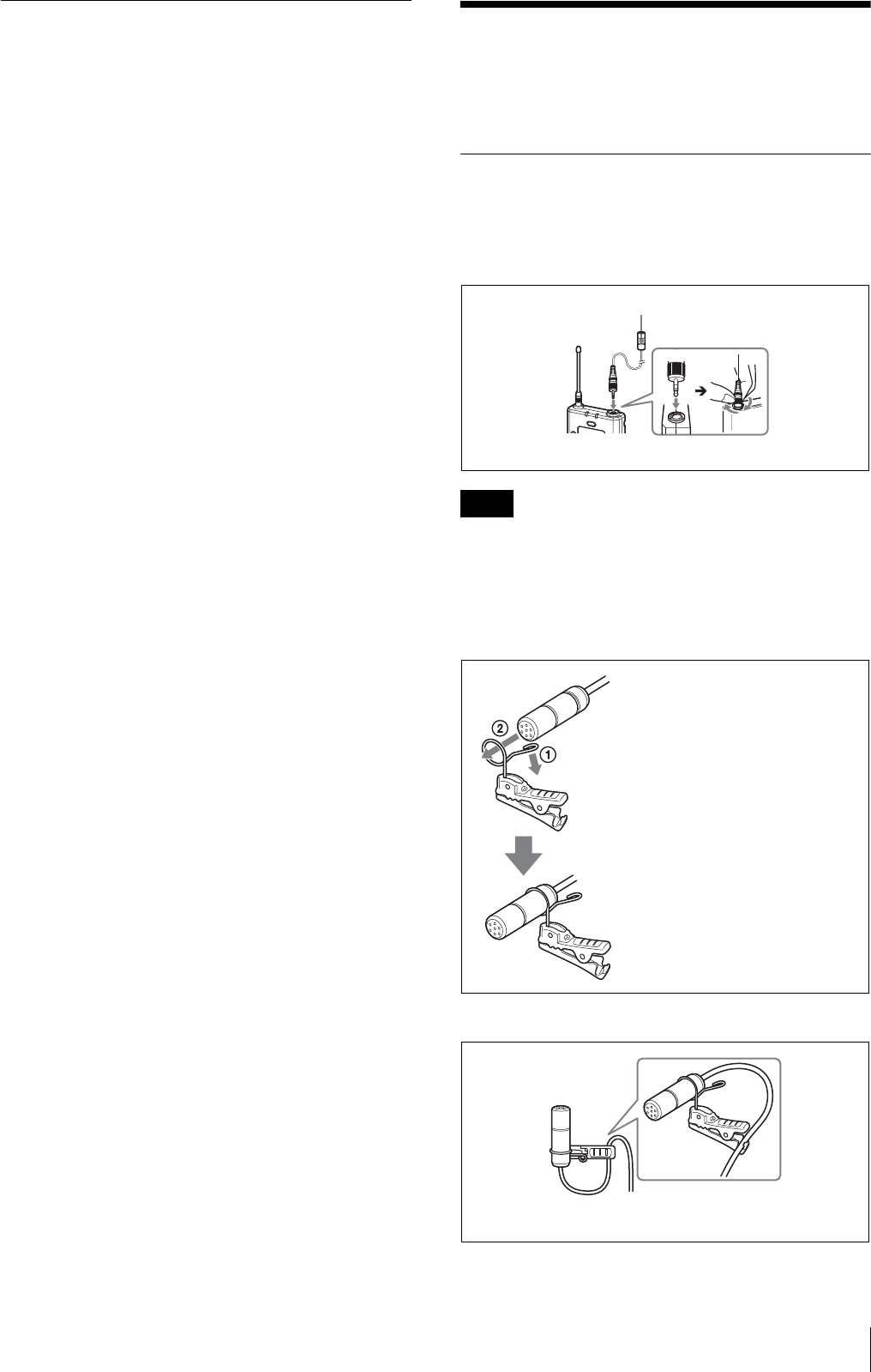
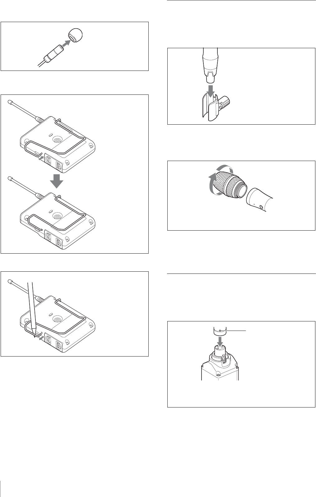
Attaching the holder clip to the
microphone
To secure the microphone cable
Note
For a secure connection, turn to lock the connector.
Microphone (supplied)
Push the end of the microphone
holder to expand the ring opening
(1), and insert the microphone (2).
Align the groove on the base of the
microphone with the ring, then
release the clip to secure the
microphone.
Insert the microphone cable through the
clamp of the holder clip.
Attaching Accessories
16
Attaching the wind screen to the
microphone
Attaching a belt clip
To remove a belt clip
Attaching accessories to the hand-
held microphone (UTX-M03)
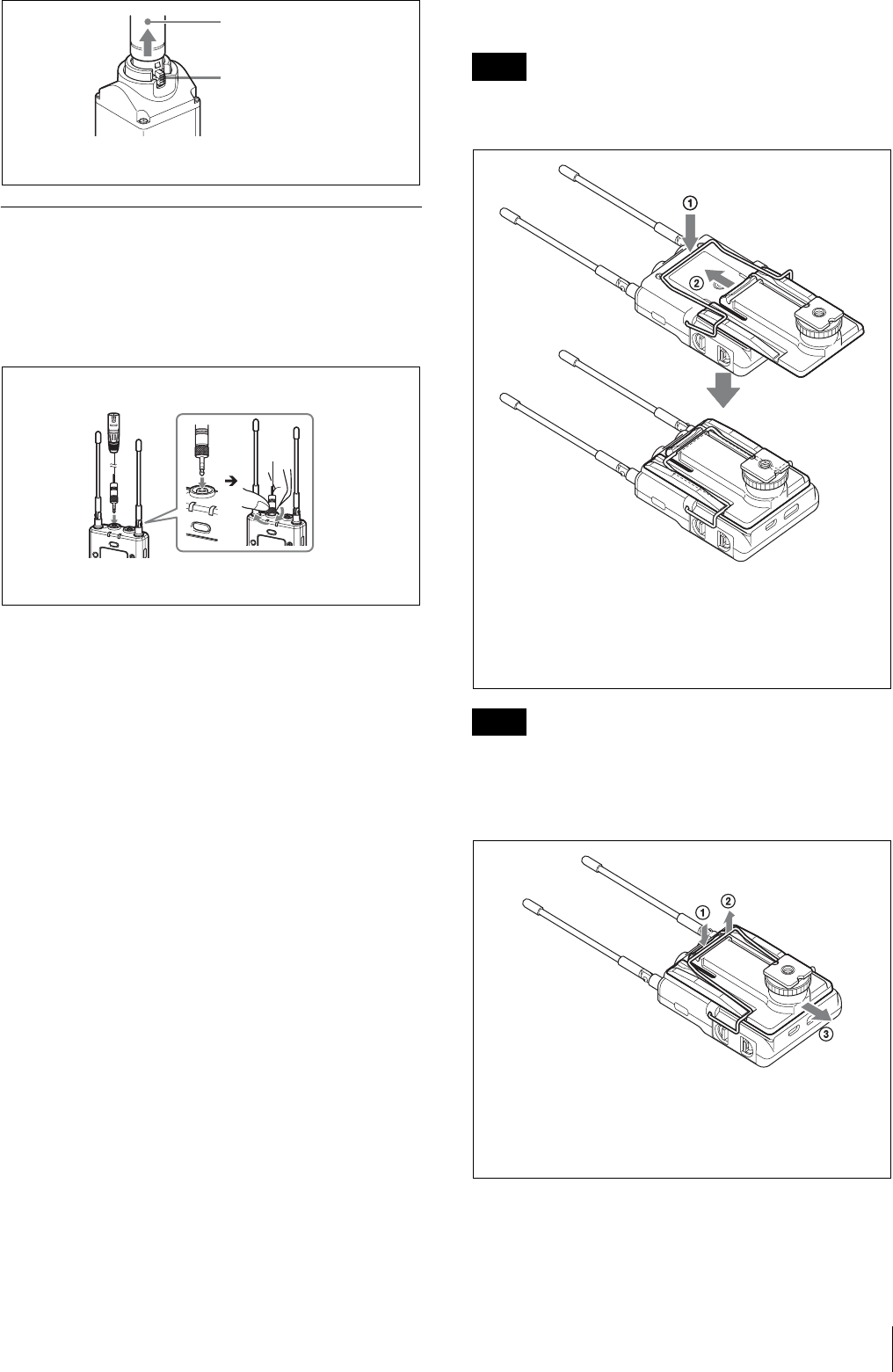
Attaching the microphone holder
Replacing the microphone unit
Removing the microphone unit
Attaching the microphone unit
Turn the microphone unit in the opposite direction from
when you removed it, and make sure that the unit is
securely attached to the microphone.
Attaching accessories to the plug-
on transmitter (UTX-P03)
Attaching a microphone or cable
Align and insert the microphone
into the hole in the wind screen.
Insert one end of the belt
clip into one of two holes
on either side of the
transmitter, and then
insert the other end into
the hole on the other side.
Insert a pointed object, such as
a ball-point pen, between the
belt clip and the transmitter,
and pry the end of the belt clip
from the hole on the side of the
transmitter.
Insert the base of the
microphone into the holder.
Turn the microphone unit in the
direction of the arrow.
Push the microphone or cable connector (XLR-3-12C
connector) into the audio input connector of the
UTX-P03 until it clicks into place.
Microphone or
cable connector
Attaching Accessories 17
Disconnecting a microphone or cable
Attaching accessories to the
portable diversity tuner (URX-P03)
Connecting the conversion cable to the
OUTPUT connector
Attaching a belt clip
See “Attaching a belt clip” (page 16).
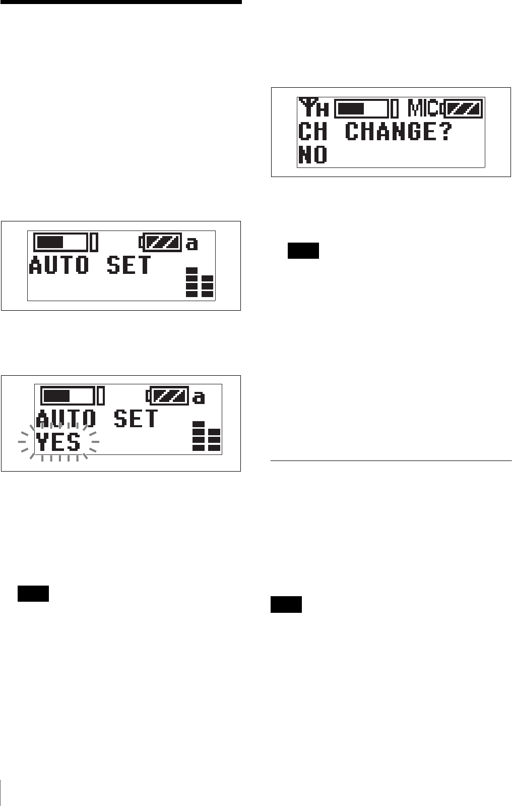
Attaching the shoe mount adapter
Attach the belt clip before attaching the shoe mount
adapter (page 16).
Attach belt clips upside-down if planning to attach the
shoe mount adapter.
If attaching a camcorder, bend the URX-P03 antenna
down so that the antenna is not reflected on the display.
To remove the shoe mount adapter
Press the release button and pull the microphone
or cable out slowly.
Release button
Microphone or
cable connector
Example: XLR-BMP conversion output
cable for the URX-P03
For a secure connection, turn to lock the
connector.
Note
Note
Push the bottom of the belt clip to make some space
between the belt clip and the tuner (1), align the belt clip
with the two vertical grooves on the shoe mount adapter, and
insert the adapter in the direction of the arrow (2). Push the
shoe mount adapter in fully until the belt clip fits into the
horizontal groove on the adapter holds.
ÅuPush and hold the part labeled “PUSH” on the shoe
mount adapter 1, and disengage the horizontal part of the
belt clip from the horizontal groove on the shoe mount
adapter (2). Then, push the shoe mount adapter in the
direction of the arrow (3).
Operation
18
Operation
Procedure for UWP series devices (UTX-B03/
M03/P03 and URX-P03)
1
Connect the tuner as required.
For details about example connections, see “System
Configuration Examples” (page 29).
2
Press and hold the POWER button for at least one
second on the tuner to turn the power on.
3
Use the + or – button to display the AUTO SET
screen on the tuner.
4
Press and hold the SET button on the tuner for at least
one second.
“YES” flashes on the display.
5
Press the SET button on the tuner.
Clear Channel Scan starts searching for an available
channel.
When Clear Channel Scan finishes, the channel with
the least noise and interference will be set.
When the channel is set, infrared transmission starts
automatically.
Some noise may occur when power is turned on.
Accordingly, turn down the audio input level of
devices connected to the tuner when turning the
power on.
6
Press and hold the SET button on the transmitter and
press the POWER/MUTING button to turn the power
on.
7
Place the infrared transmitter port on the tuner near
the infrared detector on the transmitter.
Information about the channel set on the tuner is sent
to the transmitter, and a prompt appears on the
transmitter display asking if you want to change to
that frequency.
8
Use the + or – button to select YES, then press the
SET button on the transmitter.
This sets the transmit channel.
• The infrared transmission from the tuner in step 5
continues for about