Sony Group UTXM03 UHF SYNTHESIZED WIRELESS MICROPHONE User Manual UWP D11 D12 D16
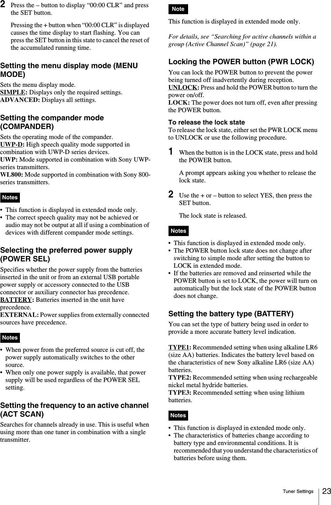
Sony Corporation UHF SYNTHESIZED WIRELESS MICROPHONE UWP D11 D12 D16
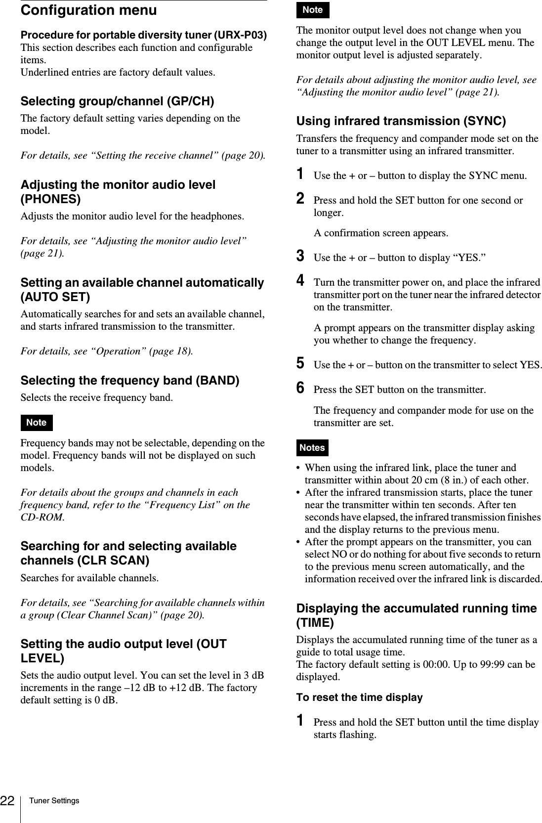
UserManual.wiki
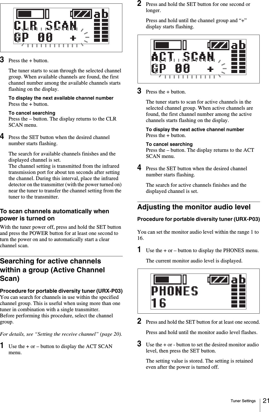
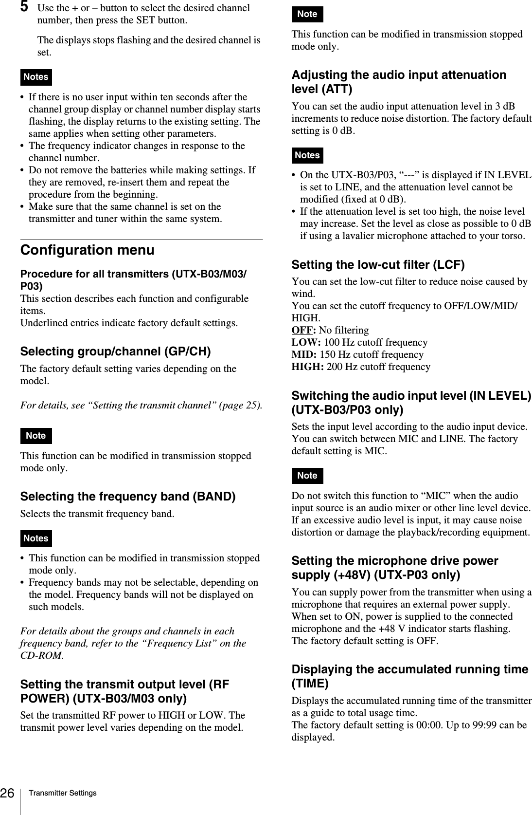
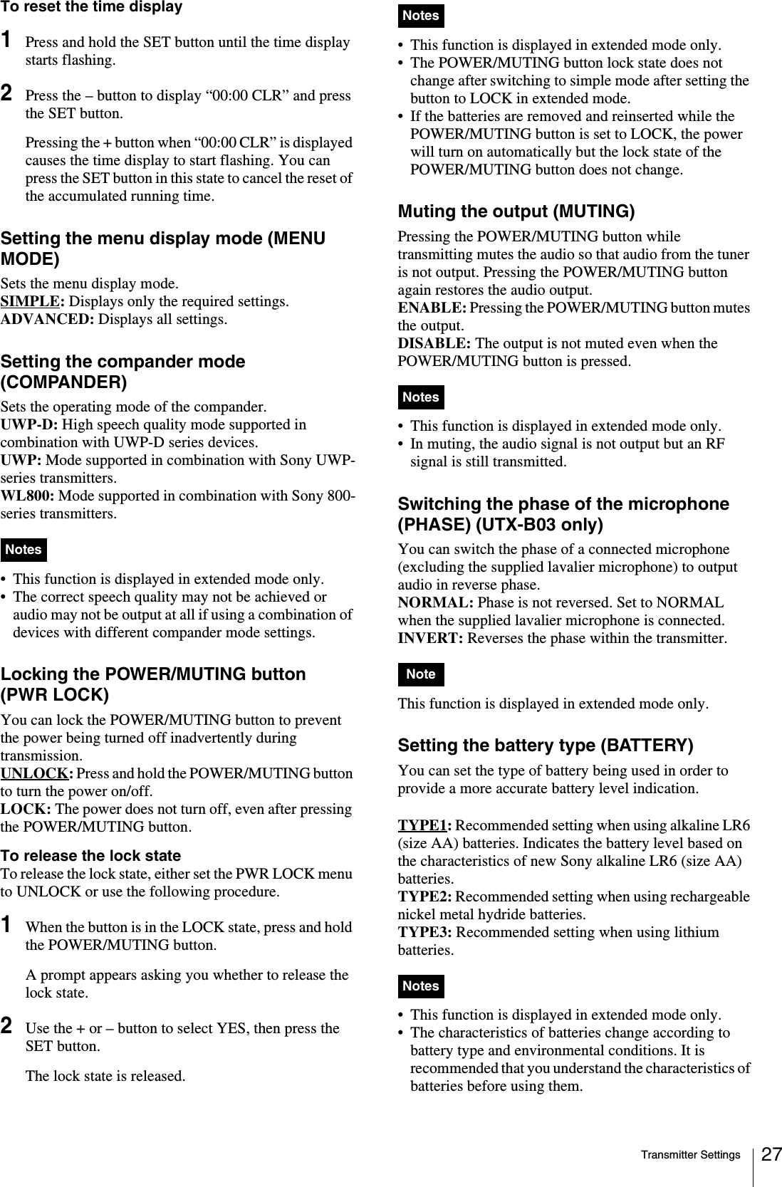
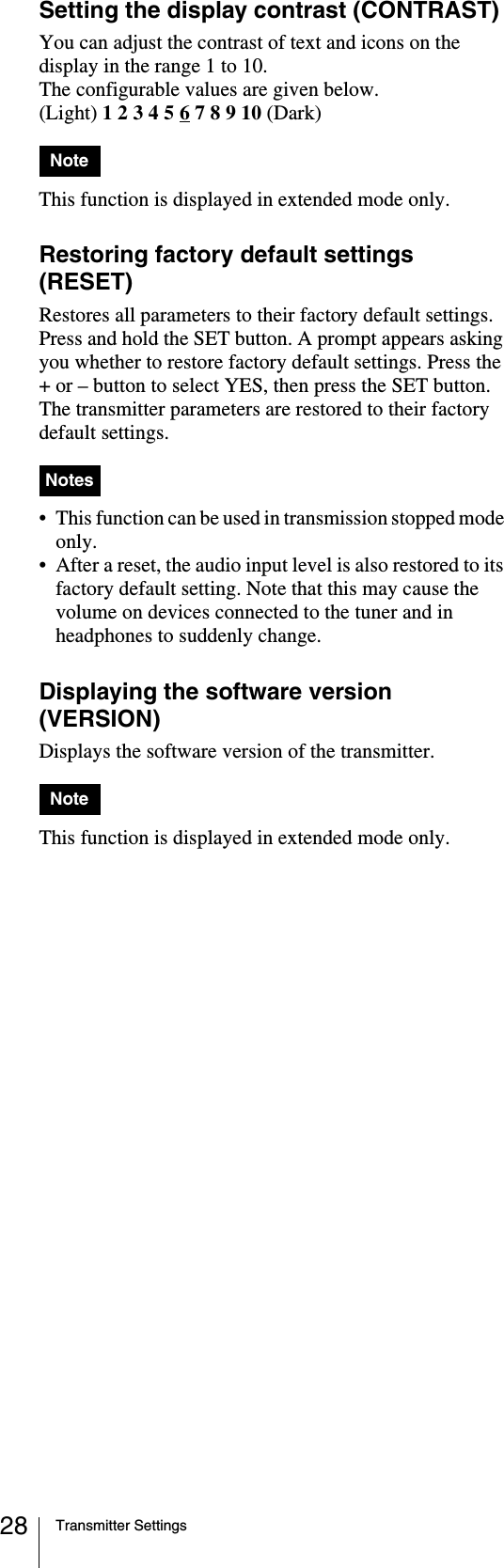
>
Sony Group
>
UTXM03 User Manual
>
Users manual
Contents
1.
Users manual
2.
Users manual(notice)
3.
05 User Manual
4.
05 User Manual_Operating Instructions
Users manual
Navigation menu
Upload a User Manual
Namespaces
Wiki Guide
HTML
PDF
Info
Views
User Manual
Discussion / Help
Navigation