Sony Group UTXM03 UHF SYNTHESIZED WIRELESS MICROPHONE User Manual UWP D11 D12 D16

Sony Corporation UHF SYNTHESIZED WIRELESS MICROPHONE UWP D11 D12 D16

Contents

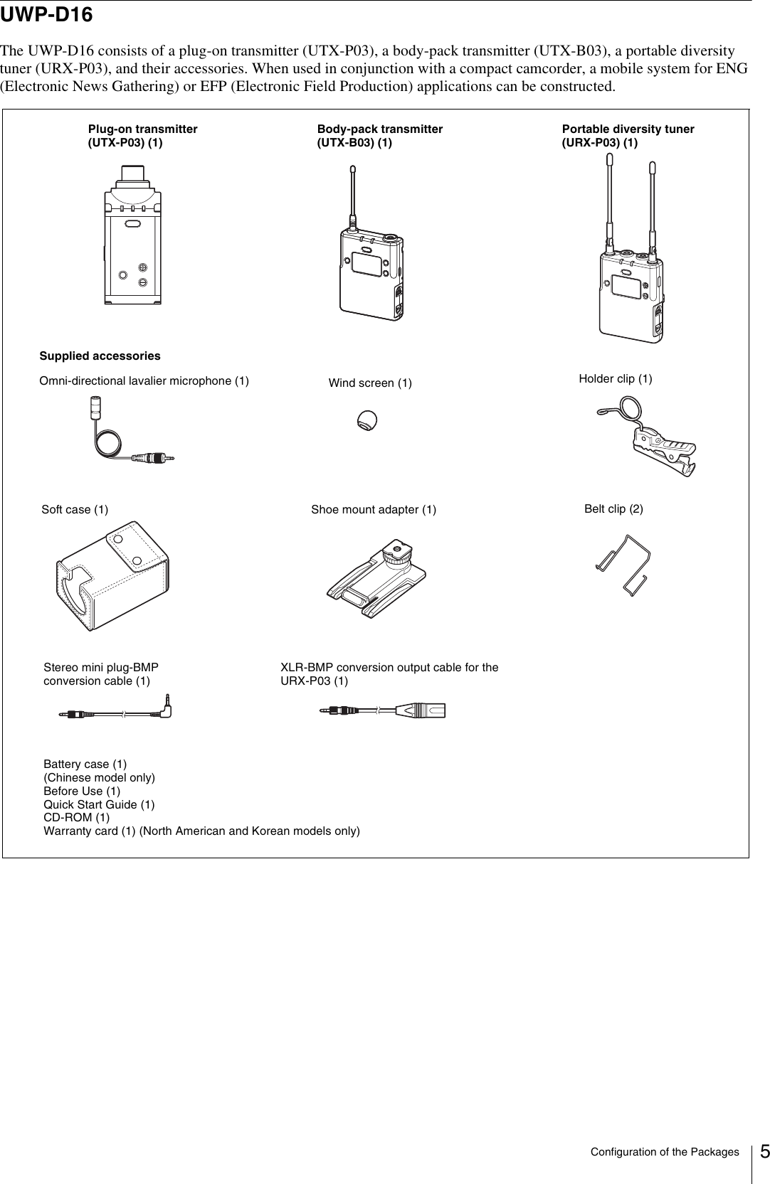
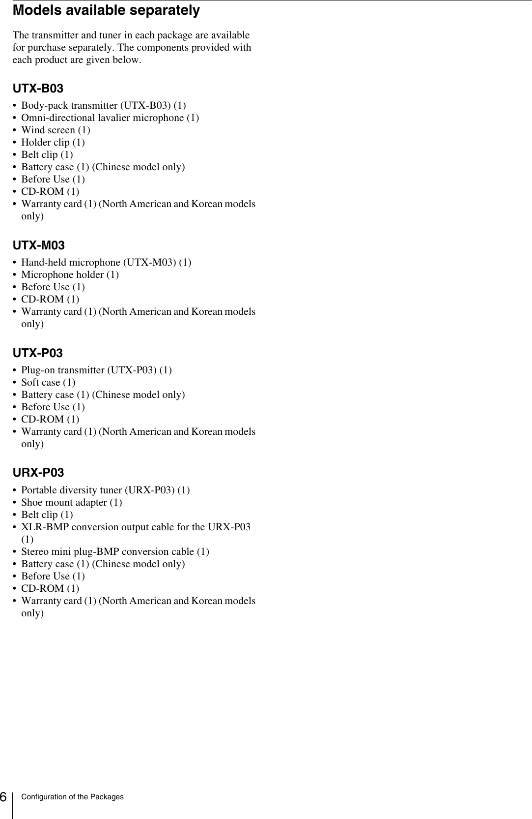
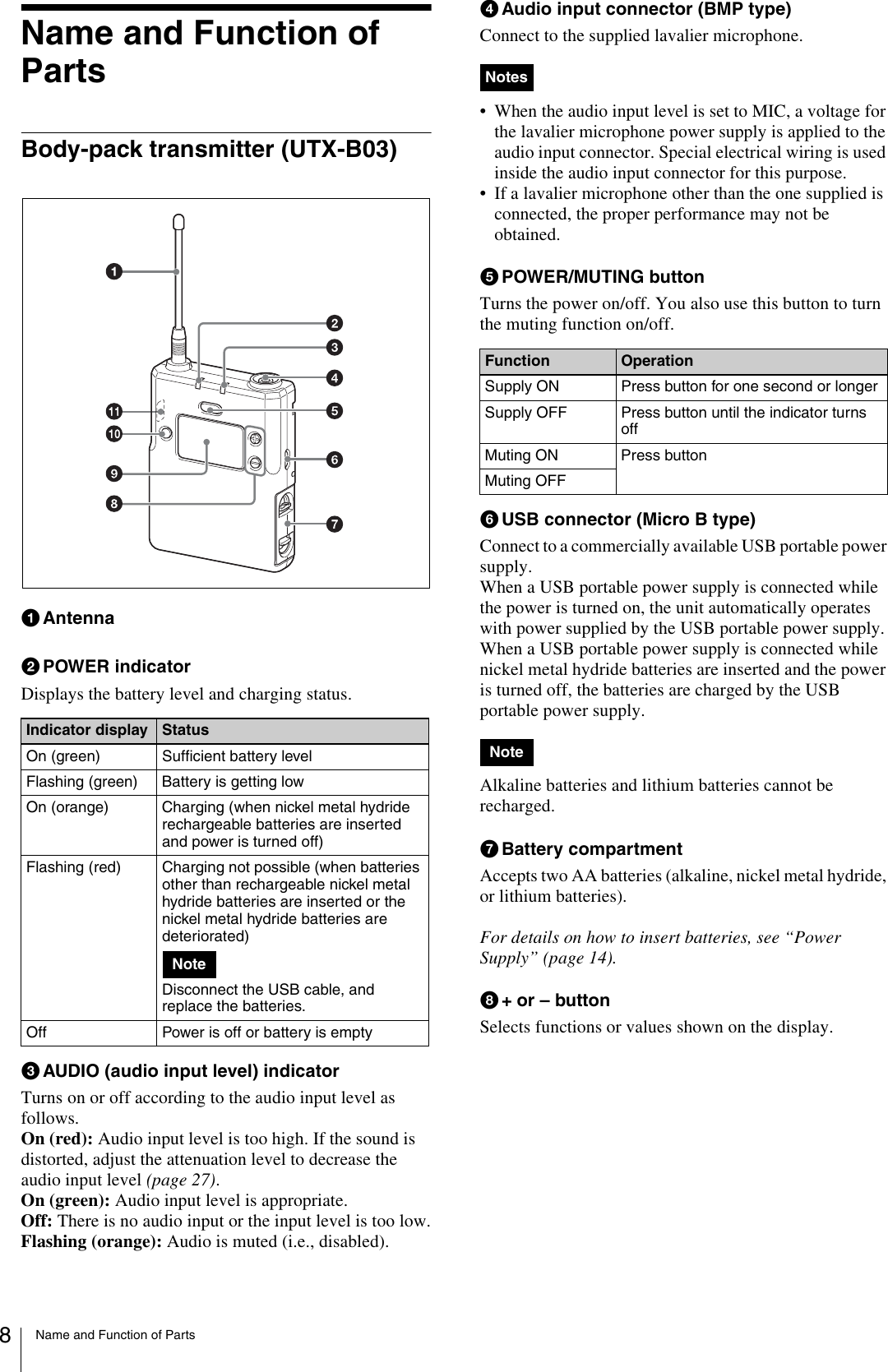
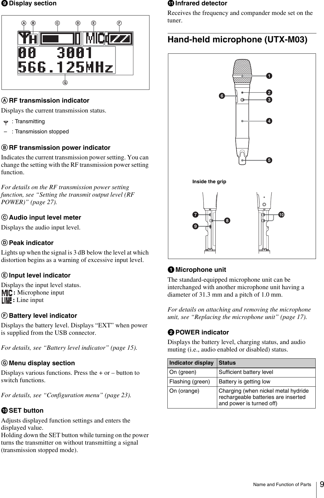
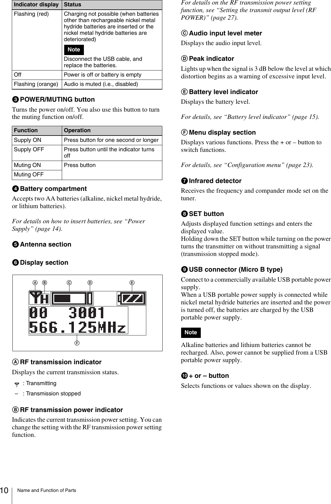
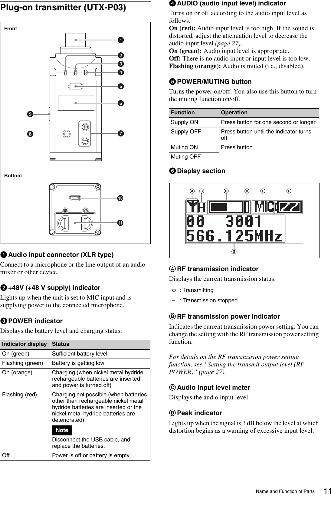
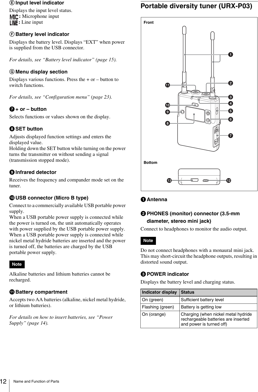
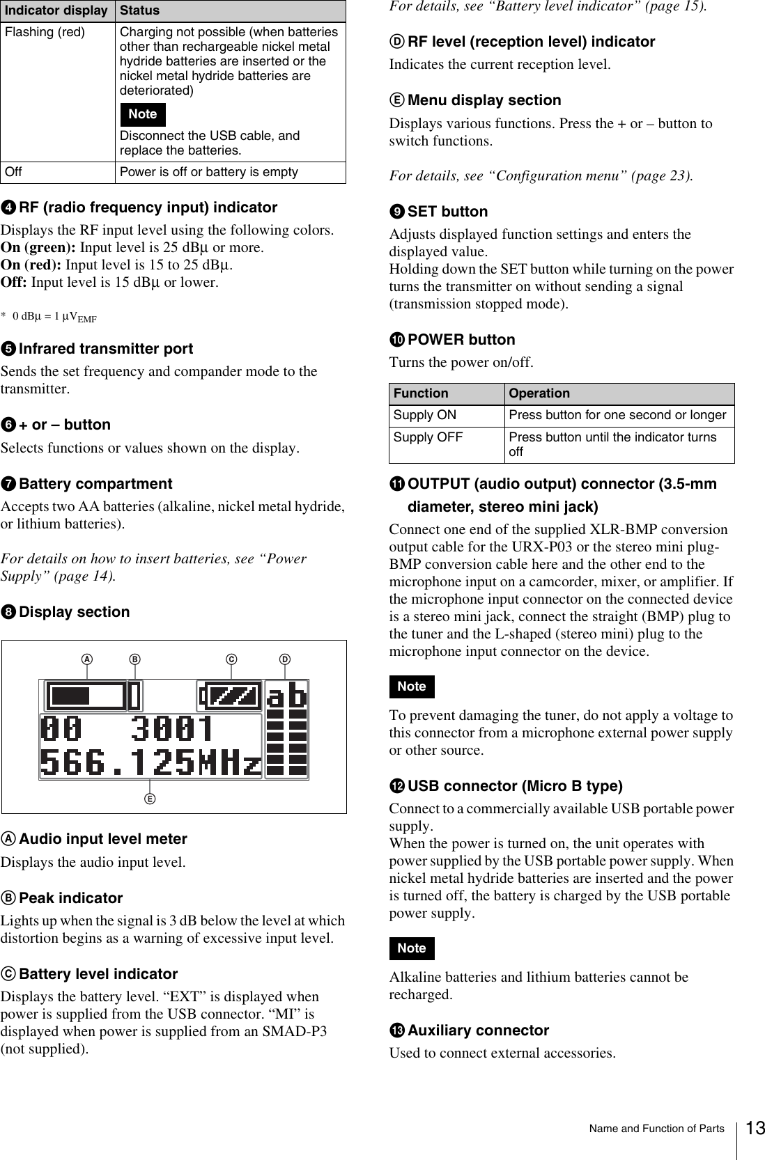
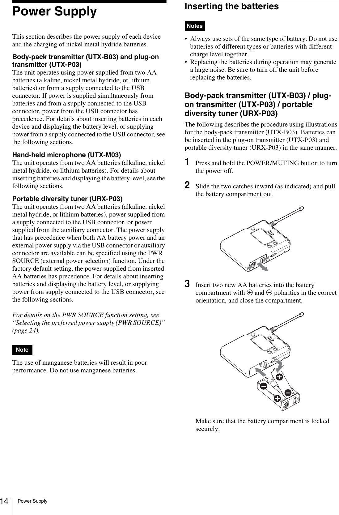
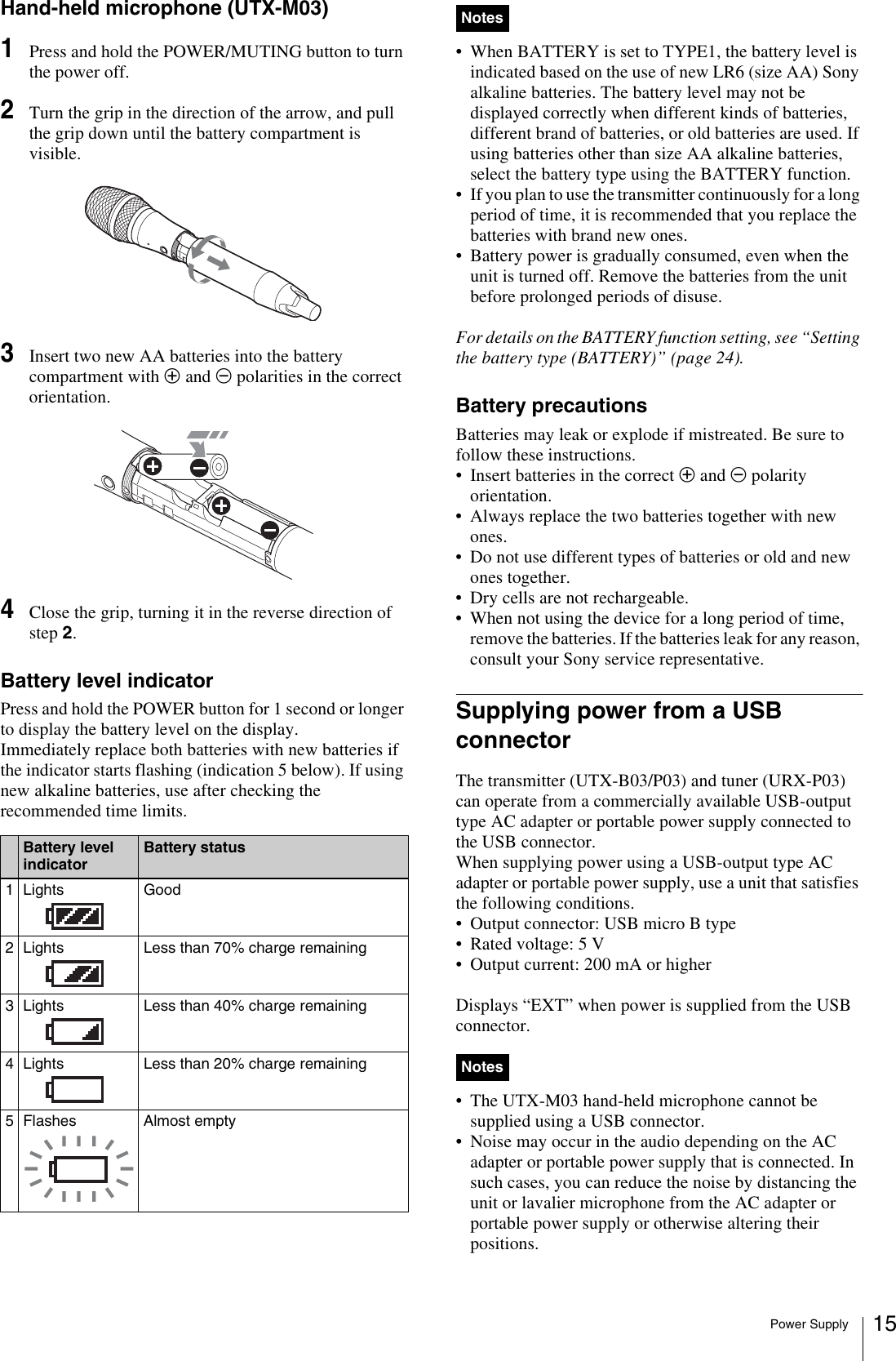
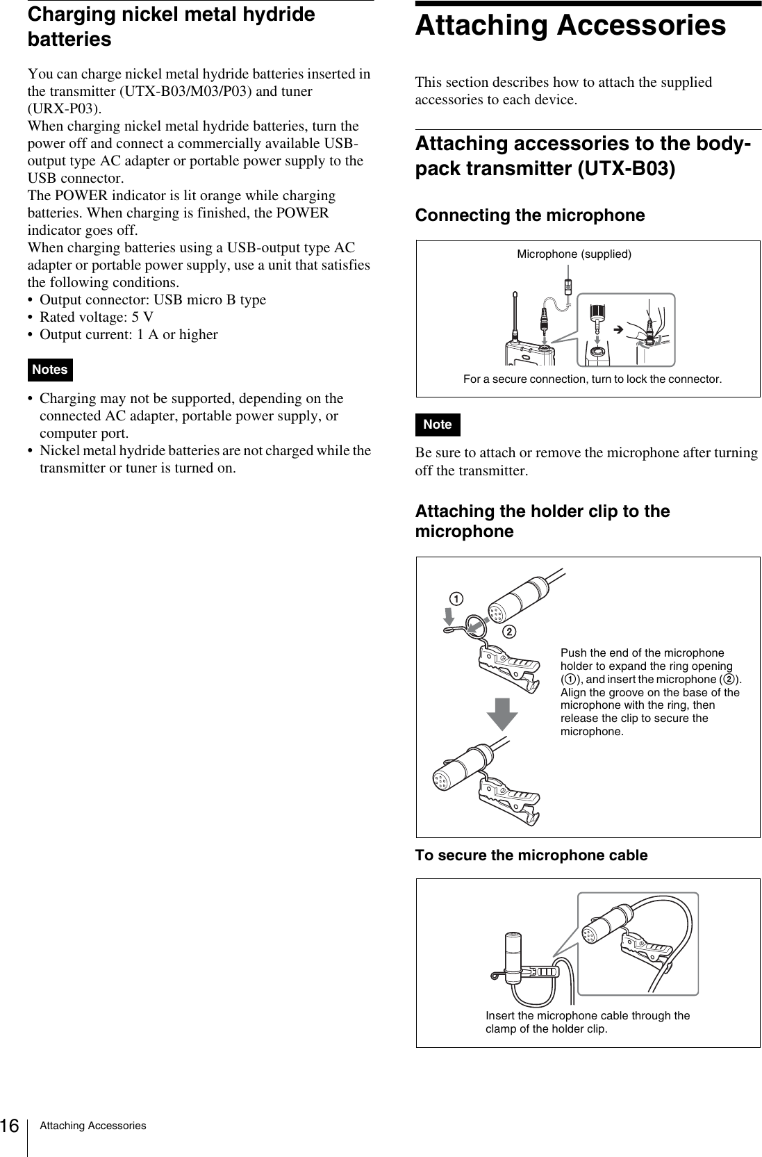
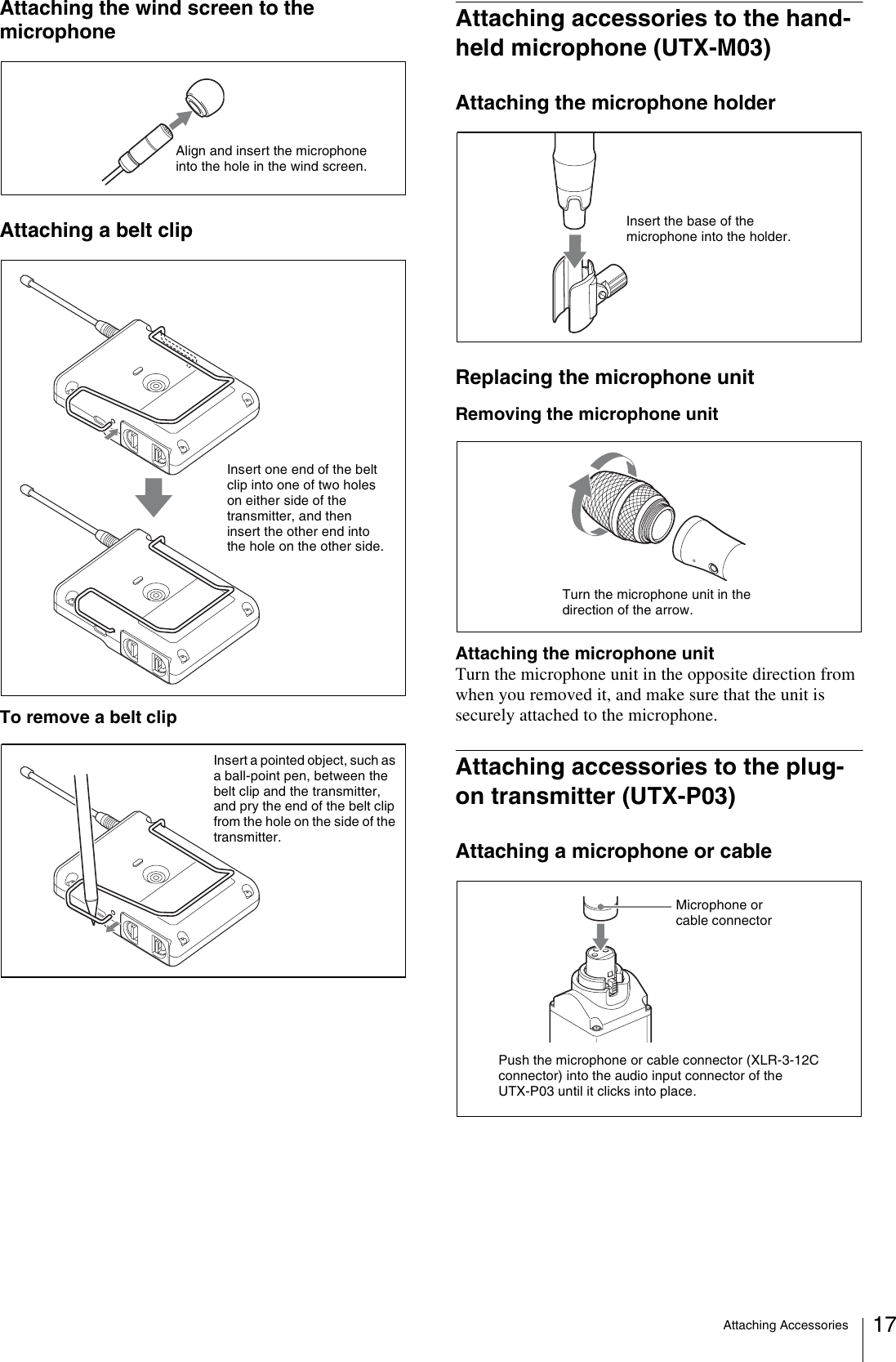
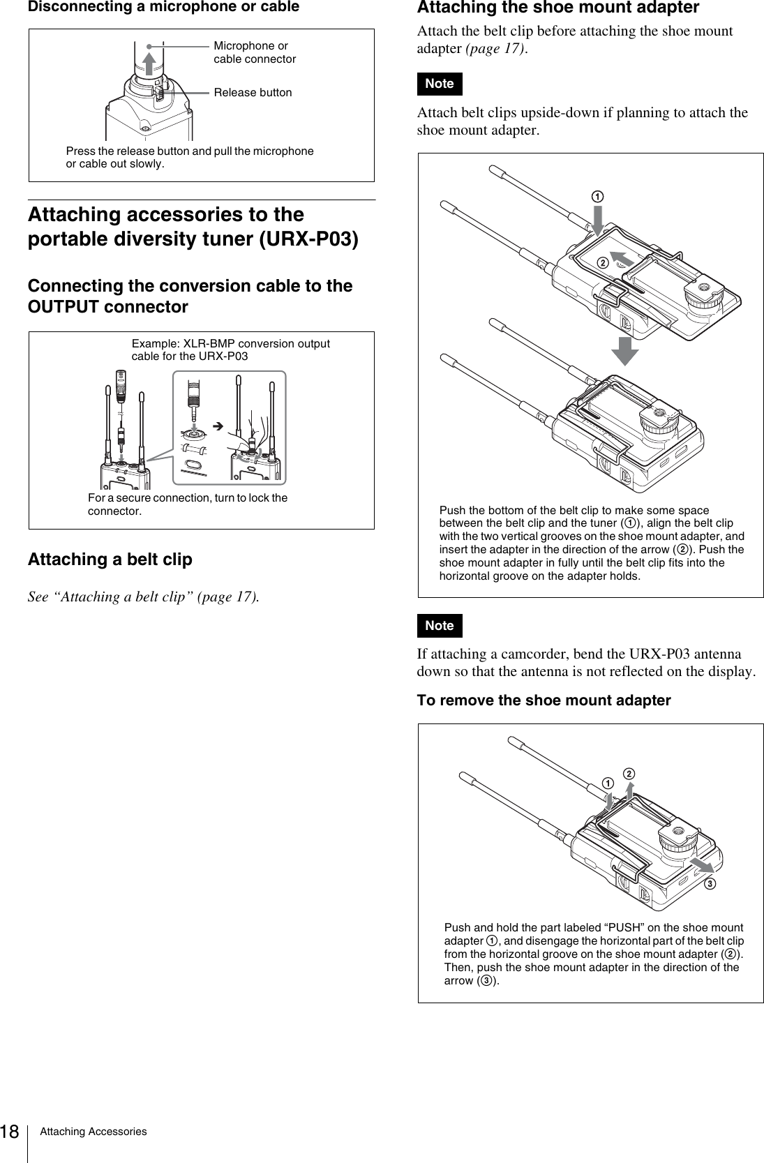
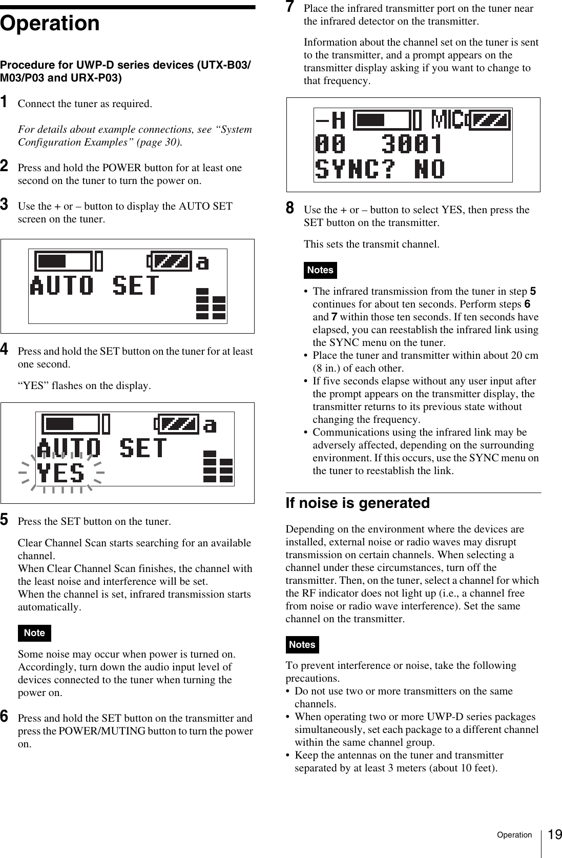
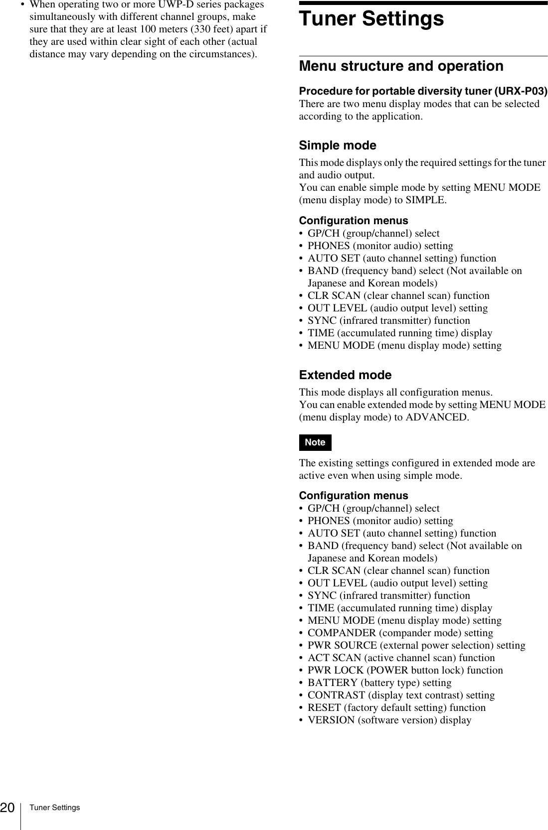
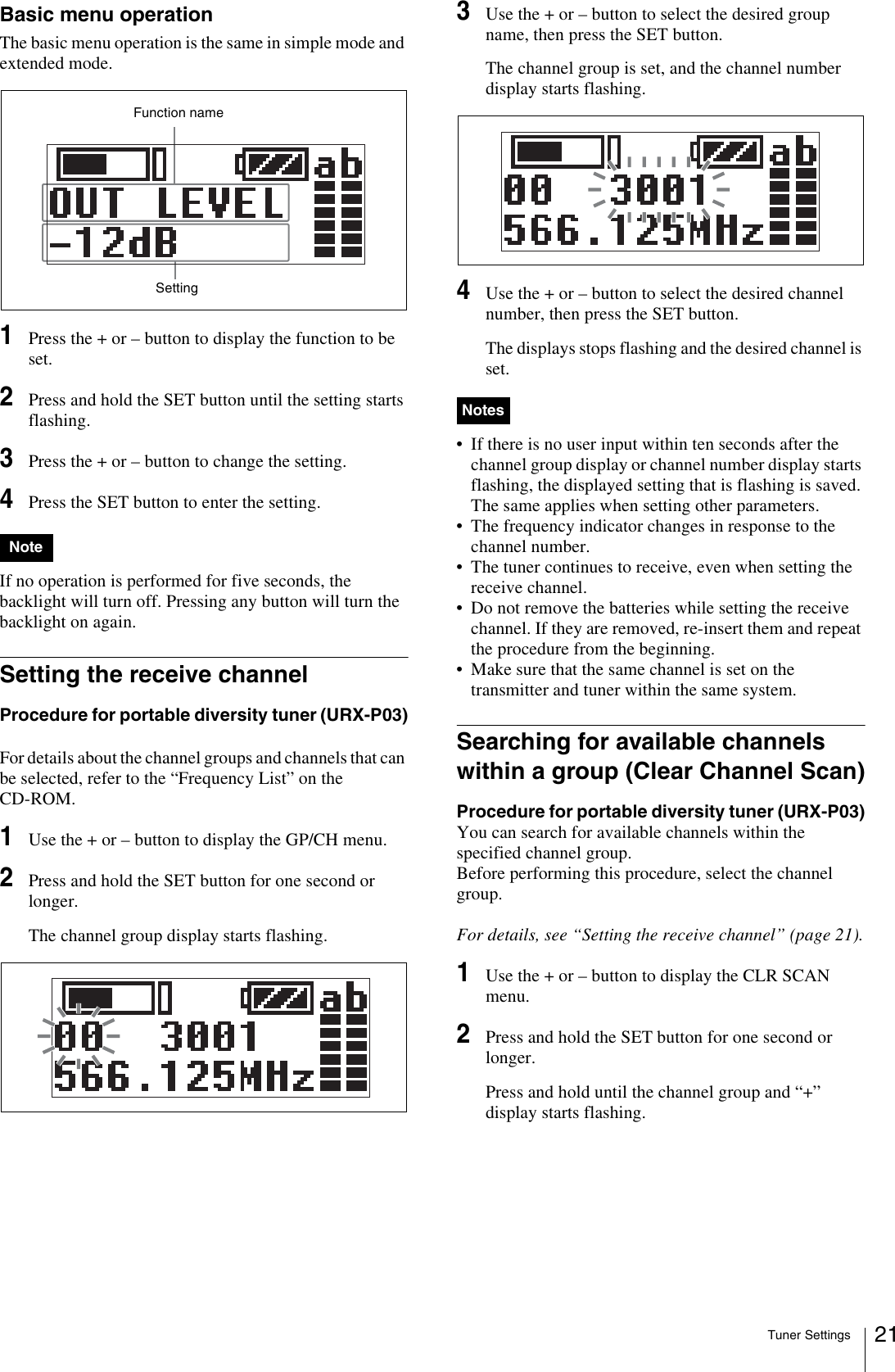
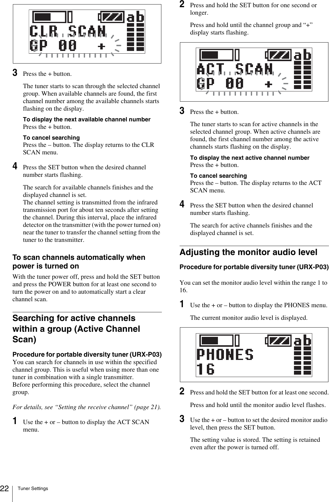
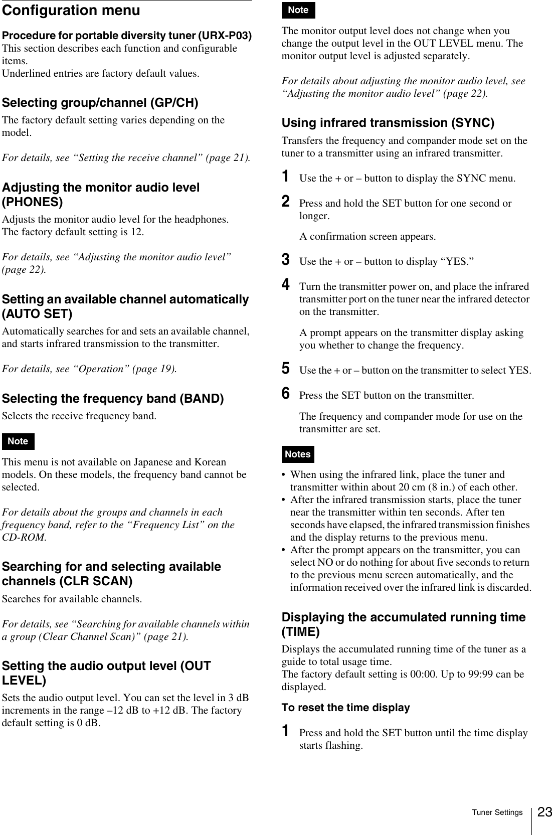
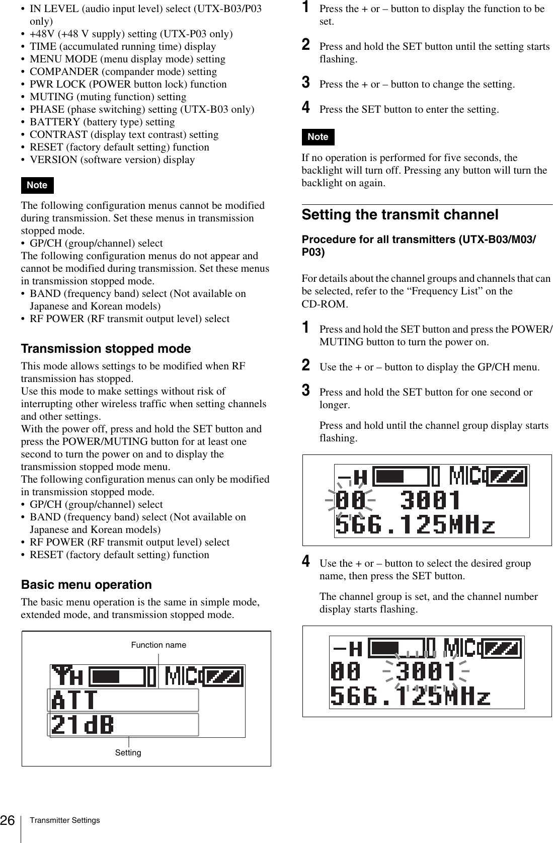
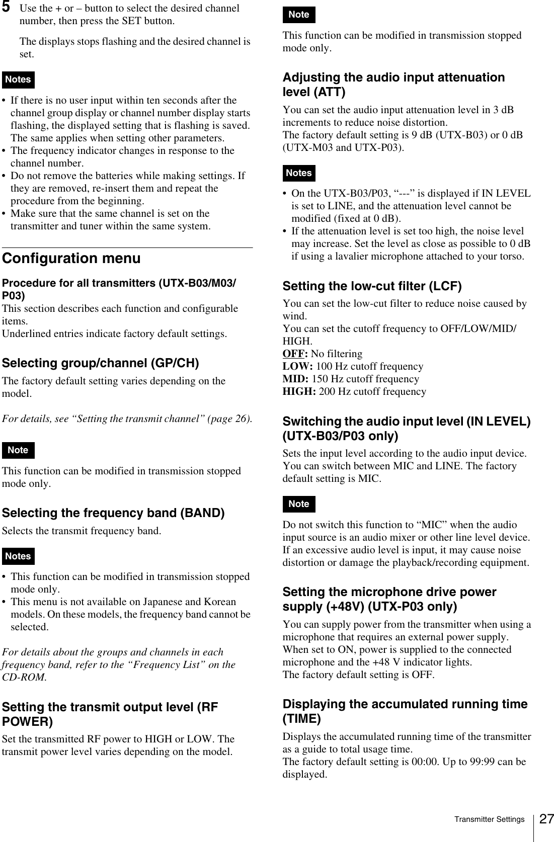
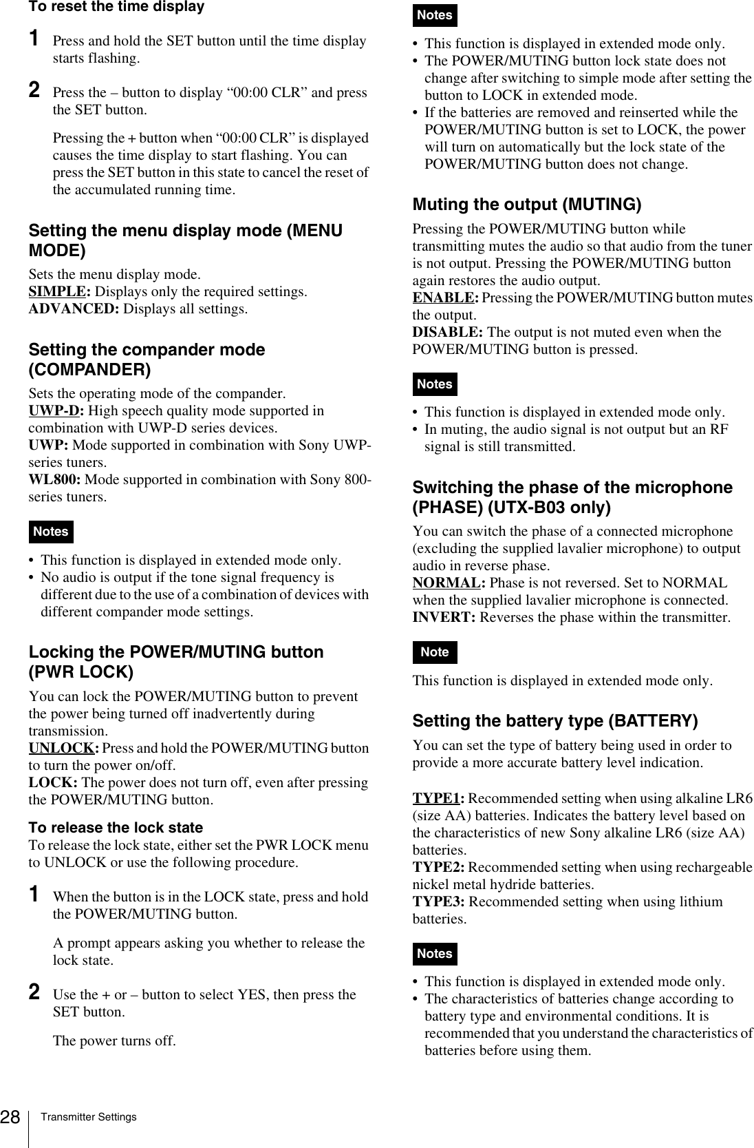
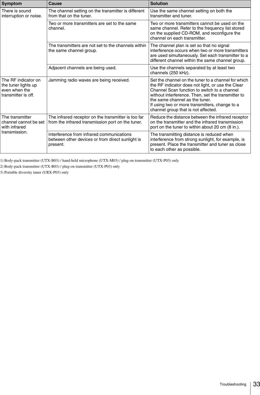
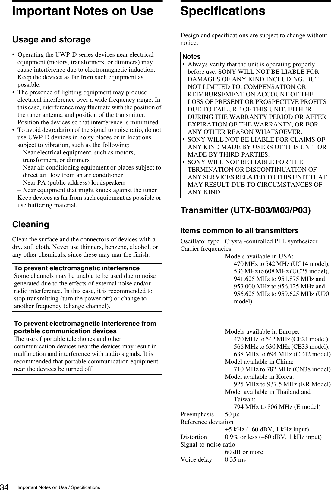
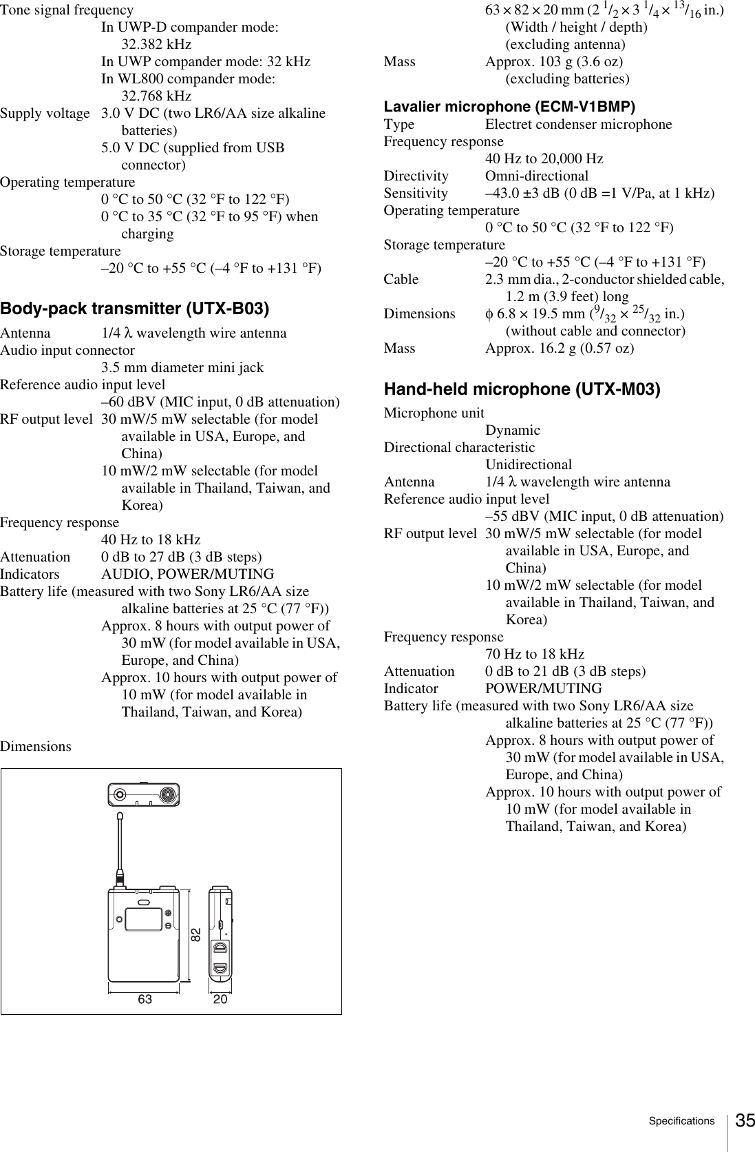
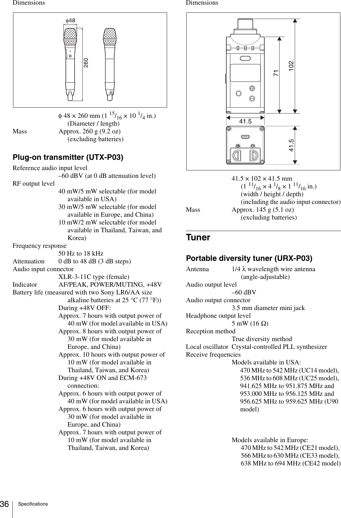
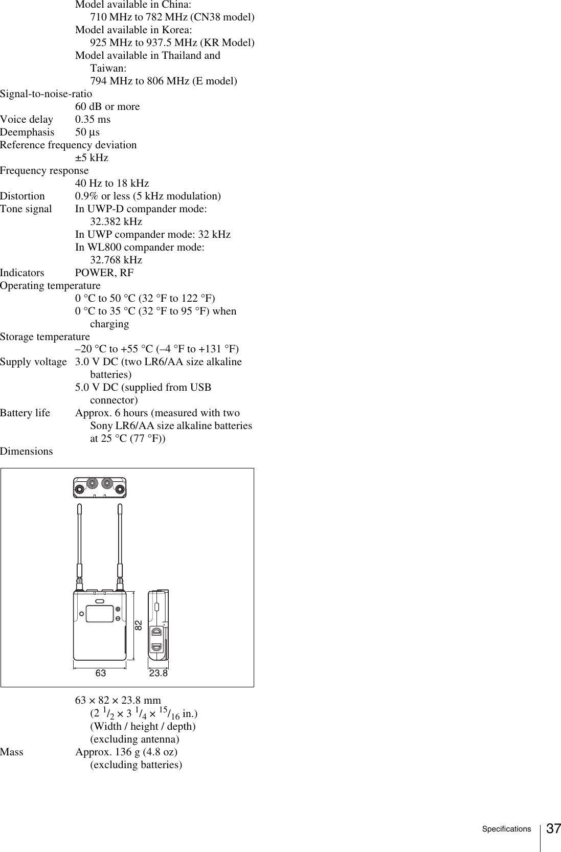
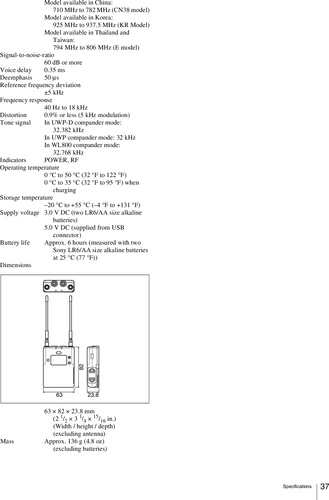
05 User Manual_Operating Instructions

Wireless MicrophonePackageOperating InstructionsBefore operating the unit, please read this manual thoroughly and retain it for future reference.UWP-D11/D12/D16UTX-B03UTX-M03UTX-P03URX-P034-530-735-18 (1)© 2014 Sony Corporation
Table of Contents2Table of ContentsConfiguration of the Packages ..................3UWP-D11 ..................................................... 3UWP-D12 ..................................................... 4UWP-D16 ..................................................... 5Models available separately.......................... 6Features .......................................................7UWP-D11 ..................................................... 7UWP-D12 ..................................................... 7UWP-D16 ..................................................... 7Name and Function of Parts.......................8Body-pack transmitter (UTX-B03)............... 8Hand-held microphone (UTX-M03)............. 9Plug-on transmitter (UTX-P03).................. 11Portable diversity tuner (URX-P03) ........... 12Power Supply.............................................14Inserting the batteries.................................. 14Supplying power from a USB connector.... 15Charging nickel metal hydride batteries..... 16Attaching Accessories..............................16Attaching accessories to the body-pack transmitter (UTX-B03)...................... 16Attaching accessories to the hand-held microphone (UTX-M03) ................... 17Attaching accessories to the plug-on transmitter (UTX-P03) ...................... 17Attaching accessories to the portable diversity tuner (URX-P03) ................ 18Operation ...................................................19If noise is generated .................................... 19Tuner Settings ...........................................20Menu structure and operation ..................... 20Setting the receive channel ......................... 21Searching for available channels within a group (Clear Channel Scan) .............. 21Searching for active channels within a group (Active Channel Scan) ...................... 22Adjusting the monitor audio level .............. 22Configuration menu.................................... 23Transmitter Settings .................................25Menu structure and operation ..................... 25Setting the transmit channel........................ 26Configuration menu.................................... 27System Configuration Examples .............30Error Messages .........................................31Troubleshooting........................................32Important Notes on Use............................34Usage and storage ....................................... 34Cleaning...................................................... 34Specifications............................................34Transmitter (UTX-B03/M03/P03).............. 34Tuner........................................................... 36
Configuration of the Packages 3Configuration of the PackagesThis manual is for the UWP-D11/D12/D16 Wireless Microphone Packages. The contents of each package are described below.Some of the packages may not be available in certain countries or areas. In addition, the U90 model can only be used in the USA.The use of U90 transmitters requires a license and is subject to restrictions on frequency selection and channel spacing.For details, consult your Sony dealer.UWP-D11The package consists of a body-pack transmitter (UTX-B03), a portable diversity tuner (URX-P03), and their accessories. When used in conjunction with a compact camcorder, a mobile system for ENG (Electronic News Gathering) or EFP (Electronic Field Production) applications can be constructed.NoteBody-pack transmitter (UTX-B03) (1)Portable diversity tuner (URX-P03) (1)Supplied accessoriesWind screen (1)Omni-directional lavalier microphone (1) Holder clip (1)Shoe mount adapter (1) Belt clip (2)Battery case (1) (Chinese model only)Before Use (1)Quick Start Guide (1)CD-ROM (1)Warranty card (1) (North American and Korean models only)Stereo mini plug-BMP conversion cable (1)XLR-BMP conversion output cable for the URX-P03 (1)
Configuration of the Packages4UWP-D12The package consists of a hand-held microphone (UTX-M03), a portable diversity tuner (URX-P03), and their accessories. When used in conjunction with a compact camcorder, a mobile system for ENG (Electronic News Gathering) or EFP (Electronic Field Production) applications can be constructed.Microphone holder (1)XLR-BMP conversion output cable for the URX-P03 (1)Shoe mount adapter (1)Belt clip (1)Battery case (1) (Chinese model only)Before Use (1)Quick Start Guide (1)CD-ROM (1)Warranty card (1) (North American and Korean models only)Stereo mini plug-BMP conversion cable (1)Supplied accessoriesHand-held microphone (UTX-M03) (1)Portable diversity tuner (URX-P03) (1)
Configuration of the Packages 5UWP-D16The UWP-D16 consists of a plug-on transmitter (UTX-P03), a body-pack transmitter (UTX-B03), a portable diversity tuner (URX-P03), and their accessories. When used in conjunction with a compact camcorder, a mobile system for ENG (Electronic News Gathering) or EFP (Electronic Field Production) applications can be constructed.Body-pack transmitter (UTX-B03) (1)Portable diversity tuner (URX-P03) (1)Supplied accessoriesSoft case (1)Plug-on transmitter (UTX-P03) (1)Shoe mount adapter (1) Belt clip (2)Wind screen (1) Holder clip (1)Stereo mini plug-BMP conversion cable (1)XLR-BMP conversion output cable for the URX-P03 (1)Omni-directional lavalier microphone (1)Battery case (1) (Chinese model only)Before Use (1)Quick Start Guide (1)CD-ROM (1)Warranty card (1) (North American and Korean models only)
Configuration of the Packages6Models available separatelyThe transmitter and tuner in each package are available for purchase separately. The components provided with each product are given below.UTX-B03• Body-pack transmitter (UTX-B03) (1)• Omni-directional lavalier microphone (1)• Wind screen (1)• Holder clip (1)• Belt clip (1)• Battery case (1) (Chinese model only)• Before Use (1)•CD-ROM (1)• Warranty card (1) (North American and Korean models only)UTX-M03• Hand-held microphone (UTX-M03) (1)• Microphone holder (1)• Before Use (1)•CD-ROM (1)• Warranty card (1) (North American and Korean models only)UTX-P03• Plug-on transmitter (UTX-P03) (1)• Soft case (1)• Battery case (1) (Chinese model only)• Before Use (1)•CD-ROM (1)• Warranty card (1) (North American and Korean models only)URX-P03• Portable diversity tuner (URX-P03) (1)• Shoe mount adapter (1)• Belt clip (1)• XLR-BMP conversion output cable for the URX-P03 (1)• Stereo mini plug-BMP conversion cable (1)• Battery case (1) (Chinese model only)• Before Use (1)•CD-ROM (1)• Warranty card (1) (North American and Korean models only)
Features 7FeaturesThe UWP-D11/D12/D16 (UWP-D series) Wireless Microphone Packages comprise a transmitter (body-pack transmitter (UTX-B03), hand-held microphone (UTX-M03), or plug-on transmitter (UTX-P03)) and a receiver (portable diversity tuner (URX-P03)). In combination with a compact camcorder or interchangeable-lens digital camera, the packages can be used for various purposes, such as ENG (Electronic News Gathering), EFP (Electronic Field Production), sports events, and weddings. They are equipped with a DSP for transmission of high-quality sound using digital compander processing. They can be used in combination with current Sony analog wireless microphone systems (UWP series, WRT series, WRR series, WRU series) by switching the compander mode.The frequency and compander mode set on the tuner can be sent to the transmitter using an infrared communications link. Used in combination with the Clear Channel Scan function of the tuner, this greatly reduces the time required to set channels.The contents of each package are described below.UWP-D11Body-pack transmitter (UTX-B03)This transmitter is a lightweight, compact transmitter that employs a crystal-controlled PLL synthesizer. It is equipped with a muting function and a BMP-type microphone input connector. The RF power output can be switched between high and low. It is also equipped with a MIC/LINE input switching function to support a variety of input levels.Portable diversity tuner (URX-P03)This tuner employs a true diversity method featuring little signal dropout and an angle-adjustable antenna. It comes with an adapter for mounting on a compact camcorder (HXR-NX3, etc.). It also features a Clear Channel Scan function to search for available channels automatically.UWP-D12Hand-held microphone (UTX-M03)This microphone features a robust, metallic body. It has a muting function and attenuator adjustment function to support a wide audio input level range.It can be used in diverse applications simply by changing the microphone capsule. It has a built-in antenna.* Microphone unit mounting dimensions: 31.3 mm diameter, 1.0 mm pitchPortable diversity tuner (URX-P03)This tuner employs a true diversity method featuring little signal dropout and an angle-adjustable antenna. It comes with an adapter for mounting on a compact camcorder (HXR-NX3, etc.). It also features a Clear Channel Scan function to search for available channels automatically.UWP-D16Plug-on transmitter (UTX-P03)This transmitter is a lightweight, compact plug-on type transmitter that employs a crystal-controlled PLL synthesizer. It has a muting function and an XLR-type microphone input connector that can supply +48 V power for connecting a wide range of microphones. It is also equipped with a MIC/LINE switching function to support a variety of input levels.Body-pack transmitter (UTX-B03)This transmitter is a lightweight, compact transmitter that employs a crystal-controlled PLL synthesizer. It is equipped with a muting function and a BMP-type microphone input connector. The RF power output can be switched between high and low. It is also equipped with a MIC/LINE input switching function to support a variety of input levels.Portable diversity tuner (URX-P03)This tuner employs a true diversity method featuring little signal dropout and an angle-adjustable antenna. It comes with an adapter for mounting on a compact camcorder (HXR-NX3, etc.). It also features a Clear Channel Scan function to search for available channels automatically.
Name and Function of Parts8Name and Function of PartsBody-pack transmitter (UTX-B03)aAntennabPOWER indicatorDisplays the battery level and charging status.cAUDIO (audio input level) indicatorTurns on or off according to the audio input level as follows.On (red): Audio input level is too high. If the sound is distorted, adjust the attenuation level to decrease the audio input level (page 27).On (green): Audio input level is appropriate.Off: There is no audio input or the input level is too low.Flashing (orange): Audio is muted (i.e., disabled).dAudio input connector (BMP type)Connect to the supplied lavalier microphone.• When the audio input level is set to MIC, a voltage for the lavalier microphone power supply is applied to the audio input connector. Special electrical wiring is used inside the audio input connector for this purpose.• If a lavalier microphone other than the one supplied is connected, the proper performance may not be obtained.ePOWER/MUTING buttonTurns the power on/off. You also use this button to turn the muting function on/off.fUSB connector (Micro B type)Connect to a commercially available USB portable power supply.When a USB portable power supply is connected while the power is turned on, the unit automatically operates with power supplied by the USB portable power supply. When a USB portable power supply is connected while nickel metal hydride batteries are inserted and the power is turned off, the batteries are charged by the USB portable power supply.Alkaline batteries and lithium batteries cannot be recharged.gBattery compartmentAccepts two AA batteries (alkaline, nickel metal hydride, or lithium batteries).For details on how to insert batteries, see “Power Supply” (page 14).h+ or – buttonSelects functions or values shown on the display.Indicator display StatusOn (green) Sufficient battery levelFlashing (green) Battery is getting lowOn (orange) Charging (when nickel metal hydride rechargeable batteries are inserted and power is turned off)Flashing (red) Charging not possible (when batteries other than rechargeable nickel metal hydride batteries are inserted or the nickel metal hydride batteries are deteriorated)Disconnect the USB cable, and replace the batteries.Off Power is off or battery is emptyNoteNotesFunction OperationSupply ON Press button for one second or longerSupply OFF Press button until the indicator turns offMuting ON Press buttonMuting OFFNote
Name and Function of Parts 9iDisplay sectionARF transmission indicatorDisplays the current transmission status.BRF transmission power indicatorIndicates the current transmission power setting. You can change the setting with the RF transmission power setting function.For details on the RF transmission power setting function, see “Setting the transmit output level (RF POWER)” (page 27).CAudio input level meterDisplays the audio input level.DPeak indicatorLights up when the signal is 3 dB below the level at which distortion begins as a warning of excessive input level.EInput level indicatorDisplays the input level status.: Microphone input: Line inputFBattery level indicatorDisplays the battery level. Displays “EXT” when power is supplied from the USB connector. For details, see “Battery level indicator” (page 15).GMenu display sectionDisplays various functions. Press the + or – button to switch functions.For details, see “Configuration menu” (page 23).jSET buttonAdjusts displayed function settings and enters the displayed value.Holding down the SET button while turning on the power turns the transmitter on without transmitting a signal (transmission stopped mode).kInfrared detectorReceives the frequency and compander mode set on the tuner.Hand-held microphone (UTX-M03)aMicrophone unitThe standard-equipped microphone unit can be interchanged with another microphone unit having a diameter of 31.3 mm and a pitch of 1.0 mm.For details on attaching and removing the microphone unit, see “Replacing the microphone unit” (page 17).bPOWER indicatorDisplays the battery level, charging status, and audio muting (i.e., audio enabled or disabled) status.: Transmitting– : Transmission stoppedIndicator display StatusOn (green) Sufficient battery levelFlashing (green) Battery is getting lowOn (orange) Charging (when nickel metal hydride rechargeable batteries are inserted and power is turned off)Inside the grip
Name and Function of Parts10cPOWER/MUTING buttonTurns the power on/off. You also use this button to turn the muting function on/off.dBattery compartmentAccepts two AA batteries (alkaline, nickel metal hydride, or lithium batteries).For details on how to insert batteries, see “Power Supply” (page 14).eAntenna sectionfDisplay section ARF transmission indicatorDisplays the current transmission status.BRF transmission power indicatorIndicates the current transmission power setting. You can change the setting with the RF transmission power setting function.For details on the RF transmission power setting function, see “Setting the transmit output level (RF POWER)” (page 27).CAudio input level meterDisplays the audio input level.DPeak indicatorLights up when the signal is 3 dB below the level at which distortion begins as a warning of excessive input level.EBattery level indicatorDisplays the battery level.For details, see “Battery level indicator” (page 15).FMenu display sectionDisplays various functions. Press the + or – button to switch functions.For details, see “Configuration menu” (page 23).gInfrared detectorReceives the frequency and compander mode set on the tuner.hSET buttonAdjusts displayed function settings and enters the displayed value.Holding down the SET button while turning on the power turns the transmitter on without transmitting a signal (transmission stopped mode).iUSB connector (Micro B type)Connect to a commercially available USB portable power supply.When a USB portable power supply is connected while nickel metal hydride batteries are inserted and the power is turned off, the batteries are charged by the USB portable power supply.Alkaline batteries and lithium batteries cannot be recharged. Also, power cannot be supplied from a USB portable power supply.j+ or – buttonSelects functions or values shown on the display.Flashing (red) Charging not possible (when batteries other than rechargeable nickel metal hydride batteries are inserted or the nickel metal hydride batteries are deteriorated)Disconnect the USB cable, and replace the batteries.Off Power is off or battery is emptyFlashing (orange) Audio is muted (i.e., disabled)Function OperationSupply ON Press button for one second or longerSupply OFF Press button until the indicator turns offMuting ON Press buttonMuting OFF: Transmitting– : Transmission stoppedIndicator display StatusNoteNote
Name and Function of Parts 11Plug-on transmitter (UTX-P03)aAudio input connector (XLR type)Connect to a microphone or the line output of an audio mixer or other device.b+48V (+48 V supply) indicatorLights up when the unit is set to MIC input and is supplying power to the connected microphone. cPOWER indicatorDisplays the battery level and charging status.dAUDIO (audio input level) indicatorTurns on or off according to the audio input level as follows.On (red): Audio input level is too high. If the sound is distorted, adjust the attenuation level to decrease the audio input level (page 27).On (green): Audio input level is appropriate.Off: There is no audio input or input level is too low.Flashing (orange): Audio is muted (i.e., disabled).ePOWER/MUTING buttonTurns the power on/off. You also use this button to turn the muting function on/off.fDisplay sectionARF transmission indicatorDisplays the current transmission status.BRF transmission power indicatorIndicates the current transmission power setting. You can change the setting with the RF transmission power setting function.For details on the RF transmission power setting function, see “Setting the transmit output level (RF POWER)” (page 27).CAudio input level meterDisplays the audio input level.DPeak indicatorLights up when the signal is 3 dB below the level at which distortion begins as a warning of excessive input level.Indicator display StatusOn (green) Sufficient battery levelFlashing (green) Battery is getting lowOn (orange) Charging (when nickel metal hydride rechargeable batteries are inserted and power is turned off)Flashing (red) Charging not possible (when batteries other than rechargeable nickel metal hydride batteries are inserted or the nickel metal hydride batteries are deteriorated)Disconnect the USB cable, and replace the batteries.Off Power is off or battery is emptyFrontBottomNoteFunction OperationSupply ON Press button for one second or longerSupply OFF Press button until the indicator turns offMuting ON Press buttonMuting OFF: Transmitting– : Transmission stopped
Name and Function of Parts12EInput level indicatorDisplays the input level status.: Microphone input: Line inputFBattery level indicatorDisplays the battery level. Displays “EXT” when power is supplied from the USB connector. For details, see “Battery level indicator” (page 15).GMenu display sectionDisplays various functions. Press the + or – button to switch functions.For details, see “Configuration menu” (page 23).g+ or – buttonSelects functions or values shown on the display.hSET buttonAdjusts displayed function settings and enters the displayed value.Holding down the SET button while turning on the power turns the transmitter on without sending a signal (transmission stopped mode).iInfrared detectorReceives the frequency and compander mode set on the tuner.jUSB connector (Micro B type)Connect to a commercially available USB portable power supply.When a USB portable power supply is connected while the power is turned on, the unit automatically operates with power supplied by the USB portable power supply. When a USB portable power supply is connected while nickel metal hydride batteries are inserted and the power is turned off, the batteries are charged by the USB portable power supply.Alkaline batteries and lithium batteries cannot be recharged.kBattery compartmentAccepts two AA batteries (alkaline, nickel metal hydride, or lithium batteries).For details on how to insert batteries, see “Power Supply” (page 14).Portable diversity tuner (URX-P03)aAntennabPHONES (monitor) connector (3.5-mm diameter, stereo mini jack)Connect to headphones to monitor the audio output.Do not connect headphones with a monaural mini jack. This may short-circuit the headphone outputs, resulting in distorted sound output.cPOWER indicatorDisplays the battery level and charging status.NoteNoteIndicator display StatusOn (green) Sufficient battery levelFlashing (green) Battery is getting lowOn (orange) Charging (when nickel metal hydride rechargeable batteries are inserted and power is turned off)FrontBottom
Name and Function of Parts 13dRF (radio frequency input) indicatorDisplays the RF input level using the following colors.On (green): Input level is 25 dBμ or more.On (red): Input level is 15 to 25 dBμ.Off: Input level is 15 dBμ or lower.*0 dBμ = 1 μVEMFeInfrared transmitter portSends the set frequency and compander mode to the transmitter.f+ or – buttonSelects functions or values shown on the display.gBattery compartmentAccepts two AA batteries (alkaline, nickel metal hydride, or lithium batteries).For details on how to insert batteries, see “Power Supply” (page 14).hDisplay sectionAAudio input level meterDisplays the audio input level.BPeak indicatorLights up when the signal is 3 dB below the level at which distortion begins as a warning of excessive input level.CBattery level indicatorDisplays the battery level. “EXT” is displayed when power is supplied from the USB connector. “MI” is displayed when power is supplied from an SMAD-P3 (not supplied).For details, see “Battery level indicator” (page 15).DRF level (reception level) indicatorIndicates the current reception level. EMenu display sectionDisplays various functions. Press the + or – button to switch functions.For details, see “Configuration menu” (page 23).iSET buttonAdjusts displayed function settings and enters the displayed value.Holding down the SET button while turning on the power turns the transmitter on without sending a signal (transmission stopped mode).jPOWER buttonTurns the power on/off. kOUTPUT (audio output) connector (3.5-mm diameter, stereo mini jack)Connect one end of the supplied XLR-BMP conversion output cable for the URX-P03 or the stereo mini plug-BMP conversion cable here and the other end to the microphone input on a camcorder, mixer, or amplifier. If the microphone input connector on the connected device is a stereo mini jack, connect the straight (BMP) plug to the tuner and the L-shaped (stereo mini) plug to the microphone input connector on the device.To prevent damaging the tuner, do not apply a voltage to this connector from a microphone external power supply or other source.lUSB connector (Micro B type)Connect to a commercially available USB portable power supply.When the power is turned on, the unit operates with power supplied by the USB portable power supply. When nickel metal hydride batteries are inserted and the power is turned off, the battery is charged by the USB portable power supply.Alkaline batteries and lithium batteries cannot be recharged.mAuxiliary connectorUsed to connect external accessories.Flashing (red) Charging not possible (when batteries other than rechargeable nickel metal hydride batteries are inserted or the nickel metal hydride batteries are deteriorated)Disconnect the USB cable, and replace the batteries.Off Power is off or battery is emptyIndicator display StatusNoteFunction OperationSupply ON Press button for one second or longerSupply OFF Press button until the indicator turns offNoteNote
Power Supply14Power SupplyThis section describes the power supply of each device and the charging of nickel metal hydride batteries.Body-pack transmitter (UTX-B03) and plug-on transmitter (UTX-P03)The unit operates using power supplied from two AA batteries (alkaline, nickel metal hydride, or lithium batteries) or from a supply connected to the USB connector. If power is supplied simultaneously from batteries and from a supply connected to the USB connector, power from the USB connector has precedence. For details about inserting batteries in each device and displaying the battery level, or supplying power from a supply connected to the USB connector, see the following sections.Hand-held microphone (UTX-M03)The unit operates from two AA batteries (alkaline, nickel metal hydride, or lithium batteries). For details about inserting batteries and displaying the battery level, see the following sections.Portable diversity tuner (URX-P03)The unit operates from two AA batteries (alkaline, nickel metal hydride, or lithium batteries), power supplied from a supply connected to the USB connector, or power supplied from the auxiliary connector. The power supply that has precedence when both AA battery power and an external power supply via the USB connector or auxiliary connector are available can be specified using the PWR SOURCE (external power selection) function. Under the factory default setting, the power supplied from inserted AA batteries has precedence. For details about inserting batteries and displaying the battery level, or supplying power from supply connected to the USB connector, see the following sections.For details on the PWR SOURCE function setting, see “Selecting the preferred power supply (PWR SOURCE)” (page 24).The use of manganese batteries will result in poor performance. Do not use manganese batteries.Inserting the batteries• Always use sets of the same type of battery. Do not use batteries of different types or batteries with different charge level together.• Replacing the batteries during operation may generate a large noise. Be sure to turn off the unit before replacing the batteries.Body-pack transmitter (UTX-B03) / plug-on transmitter (UTX-P03) / portable diversity tuner (URX-P03)The following describes the procedure using illustrations for the body-pack transmitter (UTX-B03). Batteries can be inserted in the plug-on transmitter (UTX-P03) and portable diversity tuner (URX-P03) in the same manner.1Press and hold the POWER/MUTING button to turn the power off.2Slide the two catches inward (as indicated) and pull the battery compartment out.3Insert two new AA batteries into the battery compartment with 3 and # polarities in the correct orientation, and close the compartment.Make sure that the battery compartment is locked securely.NoteNotes
Power Supply 15Hand-held microphone (UTX-M03)1Press and hold the POWER/MUTING button to turn the power off.2Turn the grip in the direction of the arrow, and pull the grip down until the battery compartment is visible.3Insert two new AA batteries into the battery compartment with 3 and # polarities in the correct orientation.4Close the grip, turning it in the reverse direction of step 2.Battery level indicatorPress and hold the POWER button for 1 second or longer to display the battery level on the display. Immediately replace both batteries with new batteries if the indicator starts flashing (indication 5 below). If using new alkaline batteries, use after checking the recommended time limits.• When BATTERY is set to TYPE1, the battery level is indicated based on the use of new LR6 (size AA) Sony alkaline batteries. The battery level may not be displayed correctly when different kinds of batteries, different brand of batteries, or old batteries are used. If using batteries other than size AA alkaline batteries, select the battery type using the BATTERY function.• If you plan to use the transmitter continuously for a long period of time, it is recommended that you replace the batteries with brand new ones.• Battery power is gradually consumed, even when the unit is turned off. Remove the batteries from the unit before prolonged periods of disuse.For details on the BATTERY function setting, see “Setting the battery type (BATTERY)” (page 24).Battery precautionsBatteries may leak or explode if mistreated. Be sure to follow these instructions.• Insert batteries in the correct 3 and # polarity orientation.• Always replace the two batteries together with new ones.• Do not use different types of batteries or old and new ones together.• Dry cells are not rechargeable.• When not using the device for a long period of time, remove the batteries. If the batteries leak for any reason, consult your Sony service representative.Supplying power from a USB connectorThe transmitter (UTX-B03/P03) and tuner (URX-P03) can operate from a commercially available USB-output type AC adapter or portable power supply connected to the USB connector.When supplying power using a USB-output type AC adapter or portable power supply, use a unit that satisfies the following conditions.• Output connector: USB micro B type• Rated voltage: 5 V• Output current: 200 mA or higherDisplays “EXT” when power is supplied from the USB connector. • The UTX-M03 hand-held microphone cannot be supplied using a USB connector.• Noise may occur in the audio depending on the AC adapter or portable power supply that is connected. In such cases, you can reduce the noise by distancing the unit or lavalier microphone from the AC adapter or portable power supply or otherwise altering their positions.Battery level indicatorBattery status1Lights Good2 Lights  Less than 70% charge remaining3 Lights  Less than 40% charge remaining4 Lights  Less than 20% charge remaining5 Flashes Almost emptyNotesNotes
Attaching Accessories16Charging nickel metal hydride batteriesYou can charge nickel metal hydride batteries inserted in the transmitter (UTX-B03/M03/P03) and tuner (URX-P03).When charging nickel metal hydride batteries, turn the power off and connect a commercially available USB-output type AC adapter or portable power supply to the USB connector. The POWER indicator is lit orange while charging batteries. When charging is finished, the POWER indicator goes off.When charging batteries using a USB-output type AC adapter or portable power supply, use a unit that satisfies the following conditions.• Output connector: USB micro B type• Rated voltage: 5 V• Output current: 1 A or higher• Charging may not be supported, depending on the connected AC adapter, portable power supply, or computer port.• Nickel metal hydride batteries are not charged while the transmitter or tuner is turned on.Attaching AccessoriesThis section describes how to attach the supplied accessories to each device.Attaching accessories to the body-pack transmitter (UTX-B03)Connecting the microphoneBe sure to attach or remove the microphone after turning off the transmitter.Attaching the holder clip to the microphoneTo secure the microphone cableNotesNoteFor a secure connection, turn to lock the connector.Microphone (supplied)Push the end of the microphone holder to expand the ring opening (1), and insert the microphone (2). Align the groove on the base of the microphone with the ring, then release the clip to secure the microphone.Insert the microphone cable through the clamp of the holder clip.
Attaching Accessories 17Attaching the wind screen to the microphoneAttaching a belt clipTo remove a belt clipAttaching accessories to the hand-held microphone (UTX-M03)Attaching the microphone holderReplacing the microphone unitRemoving the microphone unitAttaching the microphone unitTurn the microphone unit in the opposite direction from when you removed it, and make sure that the unit is securely attached to the microphone.Attaching accessories to the plug-on transmitter (UTX-P03)Attaching a microphone or cableAlign and insert the microphone into the hole in the wind screen.Insert one end of the belt clip into one of two holes on either side of the transmitter, and then insert the other end into the hole on the other side.Insert a pointed object, such as a ball-point pen, between the belt clip and the transmitter, and pry the end of the belt clip from the hole on the side of the transmitter.Insert the base of the microphone into the holder.Turn the microphone unit in the direction of the arrow.Push the microphone or cable connector (XLR-3-12C connector) into the audio input connector of the UTX-P03 until it clicks into place.Microphone or cable connector
Attaching Accessories18Disconnecting a microphone or cableAttaching accessories to the portable diversity tuner (URX-P03)Connecting the conversion cable to the OUTPUT connectorAttaching a belt clipSee “Attaching a belt clip” (page 17).Attaching the shoe mount adapterAttach the belt clip before attaching the shoe mount adapter (page 17).Attach belt clips upside-down if planning to attach the shoe mount adapter.If attaching a camcorder, bend the URX-P03 antenna down so that the antenna is not reflected on the display.To remove the shoe mount adapterPress the release button and pull the microphone or cable out slowly.Release buttonMicrophone or cable connectorExample: XLR-BMP conversion output cable for the URX-P03For a secure connection, turn to lock the connector.NoteNotePush the bottom of the belt clip to make some space between the belt clip and the tuner (1), align the belt clip with the two vertical grooves on the shoe mount adapter, and insert the adapter in the direction of the arrow (2). Push the shoe mount adapter in fully until the belt clip fits into the horizontal groove on the adapter holds.Push and hold the part labeled “PUSH” on the shoe mount adapter 1, and disengage the horizontal part of the belt clip from the horizontal groove on the shoe mount adapter (2). Then, push the shoe mount adapter in the direction of the arrow (3).
Operation 19OperationProcedure for UWP-D series devices (UTX-B03/M03/P03 and URX-P03)1Connect the tuner as required.For details about example connections, see “System Configuration Examples” (page 30).2Press and hold the POWER button for at least one second on the tuner to turn the power on.3Use the + or – button to display the AUTO SET screen on the tuner.4Press and hold the SET button on the tuner for at least one second.“YES” flashes on the display.5Press the SET button on the tuner.Clear Channel Scan starts searching for an available channel.When Clear Channel Scan finishes, the channel with the least noise and interference will be set.When the channel is set, infrared transmission starts automatically. Some noise may occur when power is turned on. Accordingly, turn down the audio input level of devices connected to the tuner when turning the power on.6Press and hold the SET button on the transmitter and press the POWER/MUTING button to turn the power on.7Place the infrared transmitter port on the tuner near the infrared detector on the transmitter.Information about the channel set on the tuner is sent to the transmitter, and a prompt appears on the transmitter display asking if you want to change to that frequency.8Use the + or – button to select YES, then press the SET button on the transmitter.This sets the transmit channel. • The infrared transmission from the tuner in step 5 continues for about ten seconds. Perform steps 6 and 7 within those ten seconds. If ten seconds have elapsed, you can reestablish the infrared link using the SYNC menu on the tuner.• Place the tuner and transmitter within about 20 cm (8 in.) of each other.• If five seconds elapse without any user input after the prompt appears on the transmitter display, the transmitter returns to its previous state without changing the frequency.• Communications using the infrared link may be adversely affected, depending on the surrounding environment. If this occurs, use the SYNC menu on the tuner to reestablish the link.If noise is generatedDepending on the environment where the devices are installed, external noise or radio waves may disrupt transmission on certain channels. When selecting a channel under these circumstances, turn off the transmitter. Then, on the tuner, select a channel for which the RF indicator does not light up (i.e., a channel free from noise or radio wave interference). Set the same channel on the transmitter.To prevent interference or noise, take the following precautions.• Do not use two or more transmitters on the same channels.• When operating two or more UWP-D series packages simultaneously, set each package to a different channel within the same channel group.• Keep the antennas on the tuner and transmitter separated by at least 3 meters (about 10 feet).NoteNotesNotes
Tuner Settings20• When operating two or more UWP-D series packages simultaneously with different channel groups, make sure that they are at least 100 meters (330 feet) apart if they are used within clear sight of each other (actual distance may vary depending on the circumstances).Tuner SettingsMenu structure and operationProcedure for portable diversity tuner (URX-P03)There are two menu display modes that can be selected according to the application.Simple modeThis mode displays only the required settings for the tuner and audio output.You can enable simple mode by setting MENU MODE (menu display mode) to SIMPLE.Configuration menus• GP/CH (group/channel) select• PHONES (monitor audio) setting• AUTO SET (auto channel setting) function• BAND (frequency band) select (Not available on Japanese and Korean models)• CLR SCAN (clear channel scan) function• OUT LEVEL (audio output level) setting• SYNC (infrared transmitter) function• TIME (accumulated running time) display• MENU MODE (menu display mode) settingExtended modeThis mode displays all configuration menus.You can enable extended mode by setting MENU MODE (menu display mode) to ADVANCED.The existing settings configured in extended mode are active even when using simple mode.Configuration menus• GP/CH (group/channel) select• PHONES (monitor audio) setting• AUTO SET (auto channel setting) function• BAND (frequency band) select (Not available on Japanese and Korean models)• CLR SCAN (clear channel scan) function• OUT LEVEL (audio output level) setting• SYNC (infrared transmitter) function• TIME (accumulated running time) display• MENU MODE (menu display mode) setting• COMPANDER (compander mode) setting• PWR SOURCE (external power selection) setting• ACT SCAN (active channel scan) function• PWR LOCK (POWER button lock) function• BATTERY (battery type) setting• CONTRAST (display text contrast) setting• RESET (factory default setting) function• VERSION (software version) displayNote
Tuner Settings 21Basic menu operationThe basic menu operation is the same in simple mode and extended mode.1Press the + or – button to display the function to be set.2Press and hold the SET button until the setting starts flashing.3Press the + or – button to change the setting.4Press the SET button to enter the setting.If no operation is performed for five seconds, the backlight will turn off. Pressing any button will turn the backlight on again.Setting the receive channelProcedure for portable diversity tuner (URX-P03)For details about the channel groups and channels that can be selected, refer to the “Frequency List” on the CD-ROM.1Use the + or – button to display the GP/CH menu.2Press and hold the SET button for one second or longer.The channel group display starts flashing. 3Use the + or – button to select the desired group name, then press the SET button.The channel group is set, and the channel number display starts flashing.4Use the + or – button to select the desired channel number, then press the SET button.The displays stops flashing and the desired channel is set.• If there is no user input within ten seconds after the channel group display or channel number display starts flashing, the displayed setting that is flashing is saved. The same applies when setting other parameters.• The frequency indicator changes in response to the channel number.• The tuner continues to receive, even when setting the receive channel.• Do not remove the batteries while setting the receive channel. If they are removed, re-insert them and repeat the procedure from the beginning.• Make sure that the same channel is set on the transmitter and tuner within the same system.Searching for available channels within a group (Clear Channel Scan)Procedure for portable diversity tuner (URX-P03)You can search for available channels within the specified channel group. Before performing this procedure, select the channel group.For details, see “Setting the receive channel” (page 21).1Use the + or – button to display the CLR SCAN menu.2Press and hold the SET button for one second or longer.Press and hold until the channel group and “+” display starts flashing.NoteFunction nameSettingNotes
Tuner Settings223Press the + button.The tuner starts to scan through the selected channel group. When available channels are found, the first channel number among the available channels starts flashing on the display.To display the next available channel numberPress the + button.To cancel searchingPress the – button. The display returns to the CLR SCAN menu.4Press the SET button when the desired channel number starts flashing.The search for available channels finishes and the displayed channel is set.The channel setting is transmitted from the infrared transmission port for about ten seconds after setting the channel. During this interval, place the infrared detector on the transmitter (with the power turned on) near the tuner to transfer the channel setting from the tuner to the transmitter.To scan channels automatically when power is turned onWith the tuner power off, press and hold the SET button and press the POWER button for at least one second to turn the power on and to automatically start a clear channel scan.Searching for active channels within a group (Active Channel Scan)Procedure for portable diversity tuner (URX-P03)You can search for channels in use within the specified channel group. This is useful when using more than one tuner in combination with a single transmitter.Before performing this procedure, select the channel group.For details, see “Setting the receive channel” (page 21).1Use the + or – button to display the ACT SCAN menu.2Press and hold the SET button for one second or longer.Press and hold until the channel group and “+” display starts flashing.3Press the + button.The tuner starts to scan for active channels in the selected channel group. When active channels are found, the first channel number among the active channels starts flashing on the display.To display the next active channel numberPress the + button.To cancel searchingPress the – button. The display returns to the ACT SCAN menu.4Press the SET button when the desired channel number starts flashing.The search for active channels finishes and the displayed channel is set.Adjusting the monitor audio levelProcedure for portable diversity tuner (URX-P03)You can set the monitor audio level within the range 1 to 16.1Use the + or – button to display the PHONES menu.The current monitor audio level is displayed.2Press and hold the SET button for at least one second.Press and hold until the monitor audio level flashes.3Use the + or – button to set the desired monitor audio level, then press the SET button.The setting value is stored. The setting is retained even after the power is turned off.
Tuner Settings 23Configuration menuProcedure for portable diversity tuner (URX-P03)This section describes each function and configurable items.Underlined entries are factory default values.Selecting group/channel (GP/CH)The factory default setting varies depending on the model.For details, see “Setting the receive channel” (page 21).Adjusting the monitor audio level (PHONES)Adjusts the monitor audio level for the headphones.The factory default setting is 12.For details, see “Adjusting the monitor audio level” (page 22).Setting an available channel automatically (AUTO SET)Automatically searches for and sets an available channel, and starts infrared transmission to the transmitter.For details, see “Operation” (page 19).Selecting the frequency band (BAND)Selects the receive frequency band.This menu is not available on Japanese and Korean models. On these models, the frequency band cannot be selected.For details about the groups and channels in each frequency band, refer to the “Frequency List” on the CD-ROM.Searching for and selecting available channels (CLR SCAN)Searches for available channels. For details, see “Searching for available channels within a group (Clear Channel Scan)” (page 21).Setting the audio output level (OUT LEVEL)Sets the audio output level. You can set the level in 3 dB increments in the range –12 dB to +12 dB. The factory default setting is 0 dB.The monitor output level does not change when you change the output level in the OUT LEVEL menu. The monitor output level is adjusted separately.For details about adjusting the monitor audio level, see “Adjusting the monitor audio level” (page 22).Using infrared transmission (SYNC)Transfers the frequency and compander mode set on the tuner to a transmitter using an infrared transmitter.1Use the + or – button to display the SYNC menu.2Press and hold the SET button for one second or longer.A confirmation screen appears.3Use the + or – button to display “YES.”4Turn the transmitter power on, and place the infrared transmitter port on the tuner near the infrared detector on the transmitter.A prompt appears on the transmitter display asking you whether to change the frequency.5Use the + or – button on the transmitter to select YES.6Press the SET button on the transmitter.The frequency and compander mode for use on the transmitter are set.• When using the infrared link, place the tuner and transmitter within about 20 cm (8 in.) of each other.• After the infrared transmission starts, place the tuner near the transmitter within ten seconds. After ten seconds have elapsed, the infrared transmission finishes and the display returns to the previous menu.• After the prompt appears on the transmitter, you can select NO or do nothing for about five seconds to return to the previous menu screen automatically, and the information received over the infrared link is discarded.Displaying the accumulated running time (TIME)Displays the accumulated running time of the tuner as a guide to total usage time. The factory default setting is 00:00. Up to 99:99 can be displayed.To reset the time display1Press and hold the SET button until the time display starts flashing.NoteNoteNotes
Tuner Settings242Press the – button to display “00:00 CLR” and press the SET button.Pressing the + button when “00:00 CLR” is displayed causes the time display to start flashing. You can press the SET button in this state to cancel the reset of the accumulated running time.Setting the menu display mode (MENU MODE)Sets the menu display mode.SIMPLE: Displays only the required settings.ADVANCED: Displays all settings.Setting the compander mode (COMPANDER)Sets the operating mode of the compander.UWP-D: High speech quality mode supported in combination with UWP-D series devices.UWP: Mode supported in combination with Sony UWP-series transmitters.WL800: Mode supported in combination with Sony 800-series transmitters.• This function is displayed in extended mode only.• No audio is output if the tone signal frequency is different due to the use of a combination of devices with different compander mode settings.Selecting the preferred power supply (PWR SOURCE)Specifies whether the power supply from the batteries inserted in the unit or from an external USB portable power supply or accessory connected to the USB connector or auxiliary connector has precedence.BATT -> EXT: Batteries inserted in the unit have precedence.EXT -> BATT: Power supplied from a USB connector or externally connected sources have precedence.BATT ONLY: Batteries inserted in the unit are used, and power supplied from the USB connector or auxiliary connector is not used even after the batteries are discharged.When BATT -> EXT or EXT -> BATT is specified and power from the preferred source is cut off, the power supply automatically switches to the other source. Therefore, when only one power supply is available, that power supply will be used regardless of the PWR SOURCE setting. There may be a brief interruption in the audio when the power supply switches.Setting the frequency to an active channel (ACT SCAN)Searches for channels already in use. This is useful when using more than one tuner in combination with a single transmitter.This function is displayed in extended mode only.For details, see “Searching for active channels within a group (Active Channel Scan)” (page 22).Locking the POWER button (PWR LOCK)You can lock the POWER button to prevent the power being turned off inadvertently during reception.UNLOCK: Press and hold the POWER button to turn the power on/off.LOCK: The power does not turn off, even after pressing the POWER button.To release the lock stateTo release the lock state, either set the PWR LOCK menu to UNLOCK or use the following procedure.1When the button is in the LOCK state, press and hold the POWER button.A prompt appears asking you whether to release the lock state.2Use the + or – button to select YES, then press the SET button.The lock state is released.• This function is displayed in extended mode only.• The POWER button lock state does not change after switching to simple mode after setting the button to LOCK in extended mode.• If the batteries are removed and reinserted while the POWER button is set to LOCK, the power will turn on automatically but the lock state of the POWER button does not change.Setting the battery type (BATTERY)You can set the type of battery being used in order to provide a more accurate battery level indication.TYPE1: Recommended setting when using alkaline LR6 (size AA) batteries. Indicates the battery level based on the characteristics of new Sony alkaline LR6 (size AA) batteries.TYPE2: Recommended setting when using rechargeable nickel metal hydride batteries. TYPE3: Recommended setting when using lithium batteries. NotesNoteNoteNotes
Transmitter Settings 25• This function is displayed in extended mode only.• The characteristics of batteries change according to battery type and environmental conditions. It is recommended that you understand the characteristics of batteries before using them.Setting the display contrast (CONTRAST)You can adjust the contrast of text and icons on the display in the range 1 to 10.The configurable values are given below.(Light) 1 2 3 4 5 6 7 8 9 10 (Dark)This function is displayed in extended mode only.Restoring factory default settings (RESET)Restores all parameters to their factory default settings.Press and hold the SET button. A prompt appears asking you whether to restore factory default settings. Press the + or – button to select YES, then press the SET button. The tuner parameters are restored to their factory default settings.• This function is displayed in extended mode only.• After a reset, the audio output level and monitor output level are also restored to their factory default settings. Note that this may cause the volume on connected devices and in headphones to suddenly change.Displaying the software version (VERSION)Displays the software version of the tuner. This function is displayed in extended mode only.Transmitter SettingsMenu structure and operationProcedure for all transmitters (UTX-B03/M03/P03)There are three menu display modes that can be selected according to the application.Simple modeThis mode displays only the required settings for transmitting audio.You can enable simple mode by setting MENU MODE (menu display mode) to SIMPLE.Configuration menus• GP/CH (group/channel) select• BAND (frequency band) select (Not available on Japanese and Korean models)• RF POWER (RF transmit output level) select• ATT (attenuator) setting• LCF (low-cut filter) setting• IN LEVEL (audio input level) select (UTX-B03/P03 only)• +48V (+48 V supply) setting (UTX-P03 only)• TIME (accumulated running time) display• MENU MODE (menu display mode) settingThe following configuration menus cannot be modified during transmission. Set these menus in transmission stopped mode.• GP/CH (group/channel) selectThe following configuration menus do not appear and cannot be modified during transmission. Set these menus in transmission stopped mode.• BAND (frequency band) select (Not available on Japanese and Korean models)• RF POWER (RF transmit output level) selectExtended modeThis mode displays all configuration menus.You can enable extended mode by setting MENU MODE (menu display mode) to ADVANCED.The existing settings configured in extended mode are active even when using simple mode.Configuration menus• GP/CH (group/channel) select• BAND (frequency band) select (Not available on Japanese and Korean models)• RF POWER (RF transmit output level) select• ATT (attenuator) setting• LCF (low-cut filter) settingNotesNoteNotesNoteNotesNote
Transmitter Settings26• IN LEVEL (audio input level) select (UTX-B03/P03 only)• +48V (+48 V supply) setting (UTX-P03 only)• TIME (accumulated running time) display• MENU MODE (menu display mode) setting• COMPANDER (compander mode) setting• PWR LOCK (POWER button lock) function• MUTING (muting function) setting• PHASE (phase switching) setting (UTX-B03 only)• BATTERY (battery type) setting• CONTRAST (display text contrast) setting• RESET (factory default setting) function• VERSION (software version) displayThe following configuration menus cannot be modified during transmission. Set these menus in transmission stopped mode.• GP/CH (group/channel) selectThe following configuration menus do not appear and cannot be modified during transmission. Set these menus in transmission stopped mode.• BAND (frequency band) select (Not available on Japanese and Korean models)• RF POWER (RF transmit output level) selectTransmission stopped modeThis mode allows settings to be modified when RF transmission has stopped.Use this mode to make settings without risk of interrupting other wireless traffic when setting channels and other settings.With the power off, press and hold the SET button and press the POWER/MUTING button for at least one second to turn the power on and to display the transmission stopped mode menu.The following configuration menus can only be modified in transmission stopped mode. • GP/CH (group/channel) select• BAND (frequency band) select (Not available on Japanese and Korean models)• RF POWER (RF transmit output level) select• RESET (factory default setting) functionBasic menu operationThe basic menu operation is the same in simple mode, extended mode, and transmission stopped mode.1Press the + or – button to display the function to be set.2Press and hold the SET button until the setting starts flashing.3Press the + or – button to change the setting.4Press the SET button to enter the setting.If no operation is performed for five seconds, the backlight will turn off. Pressing any button will turn the backlight on again.Setting the transmit channelProcedure for all transmitters (UTX-B03/M03/P03)For details about the channel groups and channels that can be selected, refer to the “Frequency List” on the CD-ROM.1Press and hold the SET button and press the POWER/MUTING button to turn the power on.2Use the + or – button to display the GP/CH menu.3Press and hold the SET button for one second or longer.Press and hold until the channel group display starts flashing.4Use the + or – button to select the desired group name, then press the SET button.The channel group is set, and the channel number display starts flashing.NoteFunction nameSettingNote
Transmitter Settings 275Use the + or – button to select the desired channel number, then press the SET button.The displays stops flashing and the desired channel is set.• If there is no user input within ten seconds after the channel group display or channel number display starts flashing, the displayed setting that is flashing is saved. The same applies when setting other parameters.• The frequency indicator changes in response to the channel number.• Do not remove the batteries while making settings. If they are removed, re-insert them and repeat the procedure from the beginning.• Make sure that the same channel is set on the transmitter and tuner within the same system.Configuration menuProcedure for all transmitters (UTX-B03/M03/P03)This section describes each function and configurable items.Underlined entries indicate factory default settings.Selecting group/channel (GP/CH)The factory default setting varies depending on the model.For details, see “Setting the transmit channel” (page 26).This function can be modified in transmission stopped mode only.Selecting the frequency band (BAND)Selects the transmit frequency band. • This function can be modified in transmission stopped mode only.• This menu is not available on Japanese and Korean models. On these models, the frequency band cannot be selected.For details about the groups and channels in each frequency band, refer to the “Frequency List” on the CD-ROM.Setting the transmit output level (RF POWER)Set the transmitted RF power to HIGH or LOW. The transmit power level varies depending on the model.This function can be modified in transmission stopped mode only.Adjusting the audio input attenuation level (ATT)You can set the audio input attenuation level in 3 dB increments to reduce noise distortion.The factory default setting is 9 dB (UTX-B03) or 0 dB (UTX-M03 and UTX-P03).• On the UTX-B03/P03, “---” is displayed if IN LEVEL is set to LINE, and the attenuation level cannot be modified (fixed at 0 dB).• If the attenuation level is set too high, the noise level may increase. Set the level as close as possible to 0 dB if using a lavalier microphone attached to your torso.Setting the low-cut filter (LCF)You can set the low-cut filter to reduce noise caused by wind.You can set the cutoff frequency to OFF/LOW/MID/HIGH.OFF: No filteringLOW: 100 Hz cutoff frequencyMID: 150 Hz cutoff frequencyHIGH: 200 Hz cutoff frequencySwitching the audio input level (IN LEVEL) (UTX-B03/P03 only)Sets the input level according to the audio input device. You can switch between MIC and LINE. The factory default setting is MIC.Do not switch this function to “MIC” when the audio input source is an audio mixer or other line level device. If an excessive audio level is input, it may cause noise distortion or damage the playback/recording equipment.Setting the microphone drive power supply (+48V) (UTX-P03 only)You can supply power from the transmitter when using a microphone that requires an external power supply.When set to ON, power is supplied to the connected microphone and the +48 V indicator lights.The factory default setting is OFF.Displaying the accumulated running time (TIME)Displays the accumulated running time of the transmitter as a guide to total usage time. The factory default setting is 00:00. Up to 99:99 can be displayed.NotesNoteNotesNoteNotesNote
Transmitter Settings28To reset the time display1Press and hold the SET button until the time display starts flashing.2Press the – button to display “00:00 CLR” and press the SET button.Pressing the + button when “00:00 CLR” is displayed causes the time display to start flashing. You can press the SET button in this state to cancel the reset of the accumulated running time.Setting the menu display mode (MENU MODE)Sets the menu display mode.SIMPLE: Displays only the required settings.ADVANCED: Displays all settings.Setting the compander mode (COMPANDER)Sets the operating mode of the compander. UWP-D: High speech quality mode supported in combination with UWP-D series devices.UWP: Mode supported in combination with Sony UWP-series tuners.WL800: Mode supported in combination with Sony 800-series tuners.• This function is displayed in extended mode only.• No audio is output if the tone signal frequency is different due to the use of a combination of devices with different compander mode settings.Locking the POWER/MUTING button (PWR LOCK)You can lock the POWER/MUTING button to prevent the power being turned off inadvertently during transmission.UNLOCK: Press and hold the POWER/MUTING button to turn the power on/off.LOCK: The power does not turn off, even after pressing the POWER/MUTING button.To release the lock stateTo release the lock state, either set the PWR LOCK menu to UNLOCK or use the following procedure.1When the button is in the LOCK state, press and hold the POWER/MUTING button.A prompt appears asking you whether to release the lock state.2Use the + or – button to select YES, then press the SET button.The power turns off.• This function is displayed in extended mode only.• The POWER/MUTING button lock state does not change after switching to simple mode after setting the button to LOCK in extended mode.• If the batteries are removed and reinserted while the POWER/MUTING button is set to LOCK, the power will turn on automatically but the lock state of the POWER/MUTING button does not change.Muting the output (MUTING)Pressing the POWER/MUTING button while transmitting mutes the audio so that audio from the tuner is not output. Pressing the POWER/MUTING button again restores the audio output.ENABLE: Pressing the POWER/MUTING button mutes the output.DISABLE: The output is not muted even when the POWER/MUTING button is pressed.• This function is displayed in extended mode only.• In muting, the audio signal is not output but an RF signal is still transmitted.Switching the phase of the microphone (PHASE) (UTX-B03 only)You can switch the phase of a connected microphone (excluding the supplied lavalier microphone) to output audio in reverse phase.NORMAL: Phase is not reversed. Set to NORMAL when the supplied lavalier microphone is connected. INVERT: Reverses the phase within the transmitter.This function is displayed in extended mode only.Setting the battery type (BATTERY)You can set the type of battery being used in order to provide a more accurate battery level indication.TYPE1: Recommended setting when using alkaline LR6 (size AA) batteries. Indicates the battery level based on the characteristics of new Sony alkaline LR6 (size AA) batteries.TYPE2: Recommended setting when using rechargeable nickel metal hydride batteries. TYPE3: Recommended setting when using lithium batteries. • This function is displayed in extended mode only.• The characteristics of batteries change according to battery type and environmental conditions. It is recommended that you understand the characteristics of batteries before using them.NotesNotesNotesNoteNotes
Transmitter Settings 29Setting the display contrast (CONTRAST)You can adjust the contrast of text and icons on the display in the range 1 to 10.The configurable values are given below.(Light) 1 2 3 4 5 6 7 8 9 10 (Dark)This function is displayed in extended mode only.Restoring factory default settings (RESET)Restores all parameters to their factory default settings.Press and hold the SET button. A prompt appears asking you whether to restore factory default settings. Press the + or – button to select YES, then press the SET button. The transmitter parameters are restored to their factory default settings.• This function can be used in transmission stopped mode only.• After a reset, the audio input level is also restored to its factory default setting. Note that this may cause the volume on devices connected to the tuner and in headphones to suddenly change.Displaying the software version (VERSION)Displays the software version of the transmitter. This function is displayed in extended mode only.NoteNotesNote
System Configuration Examples30System Configuration ExamplesThe following are configuration examples for use with UWP-D series devices.Sample configuration for ENG (Electronic News Gathering) or EFP (Electronic Field Production) with a camcorderPortable diversity tuner (URX-P03) (with shoe mount adapter attached)Body-pack transmitter(UTX-B03)XDCAM EX/HDV camcorder (HXR-NX3, etc.)or1 XLR-BMP conversion output cable (supplied)Hand-held microphone(UTX-M03)
Error Messages 31Error MessagesWhen a problem occurs, one of the following error messages may appear on the display.Message Meaning SolutionEEP ERROR An error has occurred in the backup memory data. Contact your point of purchase or Sony service representative.PLL ERROR  An error occurred in the PLL synthesizer circuit. Restart the unit. If the message persists, contact your point of purchase or Sony service representative.NO TONE Audio signal output has been muted, because a tone signal different from the compander mode configured on the tuner was received.Configure the appropriate compander mode based on the transmitters you are using “Setting the compander mode (COMPANDER)” (page 24). When operating in conjunction with UWP-D series transmitters (UTX-B03, UTX-M03, etc.), set the tuner and the transmitters to the same compander mode.
Troubleshooting32TroubleshootingIf you have any problem, use the following checklist before asking for repairs. If the problem persists, contact your point of purchase or Sony service representative.Symptom Cause SolutionThe unit does not turn on.The 3 and # polarity orientation of the batteries is incorrect.Insert the batteries with the correct polarity orientation.The batteries are getting low. Replace the batteries with new ones.The battery terminals are dirty. Clean the 3 and # terminals with a cotton swab.Batteries are not inserted despite PWR SOURCE being set to BATT ONLY.3)Insert batteries, or change the PWR SOURCE setting.The unit does not turn off.The POWER/MUTING button is locked. Release the locked status in the PWR LOCK menu.The batteries become drained quickly.The batteries are getting low. Replace the batteries with new ones.Manganese batteries are being used. Use alkaline batteries. The battery life of a manganese battery is less than half that of an alkaline battery.The device is being used under cold conditions. The batteries drain quickly under cold conditions.The channel cannot be changed.1)The unit is not in transmission stopped mode. Turn off the unit, and then turn it on again while holding down the SET button to switch to transmission stopped mode.There is no sound. The channel setting on the transmitter is different from that on the tuner.Use the same channel setting on both the transmitter and tuner.The transmitter is not transmitting signals, or the transmission output is weak.Confirm that the transmitter is turned on. Alternatively, reduce the distance between the transmitter and tuner.The transmitter is set to line level input.2) Switch to microphone input.The compander mode setting on the transmitter is different from that on the tuner.Use the same compander mode setting on both the transmitter and tuner.The transmitter is muted.2) Press the POWER/MUTING button on the transmitter to release the muted state.The sound is weak. The attenuation level on the transmitter is too high. The input level of the transmitter is low. Set the attenuation of the transmitter to an appropriate level.The volume on the amplifier or mixer is low. Adjust the volume to an appropriate level.The transmitter is set to line level input.2) Switch to microphone input.The compander mode setting on the transmitter is different from that on the tuner.Use the same compander mode setting on both the transmitter and tuner.The sound is distorted.The attenuation level on the transmitter is too low or is set to 0.The input level is extremely high. Set the attenuation on the transmitter so that the audio is not distorted.The channel setting on the transmitter is different from that on the tuner.Use the same channel setting on both the transmitter and tuner.Headphones with a monaural mini jack are being used.3)Use headphones with a stereo mini jack.
Troubleshooting 331) Body-pack transmitter (UTX-B03) / hand-held microphone (UTX-M03) / plug-on transmitter (UTX-P03) only2) Body-pack transmitter (UTX-B03) / plug-on transmitter (UTX-P03) only3) Portable diversity tuner (URX-P03) onlyThere is sound interruption or noise.The channel setting on the transmitter is different from that on the tuner.Use the same channel setting on both the transmitter and tuner.Two or more transmitters are set to the same channel.Two or more transmitters cannot be used on the same channel. Refer to the frequency list stored on the supplied CD-ROM, and reconfigure the channel on each transmitter.The transmitters are not set to the channels within the same channel group.The channel plan is set so that no signal interference occurs when two or more transmitters are used simultaneously. Set each transmitter to a different channel within the same channel group.Adjacent channels are being used. Use the channels separated by at least two channels (250 kHz).The RF indicator on the tuner lights up even when the transmitter is off.Jamming radio waves are being received. Set the channel on the tuner to a channel for which the RF indicator does not light, or use the Clear Channel Scan function to switch to a channel without interference. Then, set the transmitter to the same channel as the tuner.If using two or more transmitters, change to a channel group that is not affected.The transmitter channel cannot be set with infrared transmission.The infrared receptor on the transmitter is too far from the infrared transmission port on the tuner.Reduce the distance between the infrared receptor on the transmitter and the infrared transmission port on the tuner to within about 20 cm (8 in.).Interference from infrared communications between other devices or from direct sunlight is present.The transmitting distance is reduced when interference from strong sunlight, for example, is present. Place the transmitter and tuner as close to each other as possible.Symptom Cause Solution
34 Important Notes on Use / SpecificationsImportant Notes on UseUsage and storage• Operating the UWP-D series devices near electricalequipment (motors, transformers, or dimmers) maycause interference due to electromagnetic induction.Keep the devices as far from such equipment aspossible.• The presence of lighting equipment may produceelectrical interference over a wide frequency range. Inthis case, interference may fluctuate with the position of the tuner antenna and position of the transmitter.Position the devices so that interference is minimized.• To avoid degradation of the signal to noise ratio, do notuse UWP-D devices in noisy places or in locationssubject to vibration, such as the following:– Near electrical equipment, such as motors,transformers, or dimmers– Near air conditioning equipment or places subject todirect air flow from an air conditioner– Near PA (public address) loudspeakers– Near equipment that might knock against the tunerKeep devices as far from such equipment as possible oruse buffering material.CleaningClean the surface and the connectors of devices with a dry, soft cloth. Never use thinners, benzene, alcohol, or any other chemicals, since these may mar the finish.SpecificationsDesign and specifications are subject to change without notice.Transmitter (UTX-B03/M03/P03)Items common to all transmittersOscillator type Crystal-controlled PLL synthesizerCarrier frequenciesModels available in USA:470 MHz to 542 MHz (UC14 model), 536 MHz to 608 MHz (UC25 model),    941.625 MHz to 951.875 MHz and 953.000 MHz to 956.125 MHz and 956.625 MHz to 959.625 MHz (U90 model)Models available in Europe:470 MHz to 542 MHz (CE21 model), 566 MHz to 630 MHz (CE33 model), 638 MHz to 694 MHz (CE42 model)Model available in China:710 MHz to 782 MHz (CN38 model)Model available in Korea:925 MHz to 937.5 MHz (KR Model)Model available in Thailand and Taiwan:794 MHz to 806 MHz (E model)Preemphasis 50 μs Reference deviation±5 kHz (–60 dBV, 1 kHz input)Distortion 0.9% or less (–60 dBV, 1 kHz input)Signal-to-noise-ratio60 dB or moreVoice delay 0.35 msTo prevent electromagnetic interferenceSome channels may be unable to be used due to noise generated due to the effects of external noise and/or radio interference. In this case, it is recommended to stop transmitting (turn the power off) or change to another frequency (change channel).To prevent electromagnetic interference from portable communication devicesThe use of portable telephones and other communication devices near the devices may result in malfunction and interference with audio signals. It is recommended that portable communication equipment near the devices be turned off.Notes• Always verify that the unit is operating properlybefore use. SONY WILL NOT BE LIABLE FORDAMAGES OF ANY KIND INCLUDING, BUTNOT LIMITED TO, COMPENSATION ORREIMBURSEMENT ON ACCOUNT OF THELOSS OF PRESENT OR PROSPECTIVE PROFITSDUE TO FAILURE OF THIS UNIT, EITHERDURING THE WARRANTY PERIOD OR AFTEREXPIRATION OF THE WARRANTY, OR FORANY OTHER REASON WHATSOEVER.• SONY WILL NOT BE LIABLE FOR CLAIMS OFANY KIND MADE BY USERS OF THIS UNIT ORMADE BY THIRD PARTIES.• SONY WILL NOT BE LIABLE FOR THETERMINATION OR DISCONTINUATION OFANY SERVICES RELATED TO THIS UNIT THAT MAY RESULT DUE TO CIRCUMSTANCES OFANY KIND.
Specifications 35Tone signal frequencyIn UWP-D compander mode: 32.382 kHzIn UWP compander mode: 32 kHzIn WL800 compander mode: 32.768 kHzSupply voltage 3.0 V DC (two LR6/AA size alkaline batteries)5.0 V DC (supplied from USB connector)Operating temperature0 °C to 50 °C (32 °F to 122 °F)0 °C to 35 °C (32 °F to 95 °F) when chargingStorage temperature–20 °C to +55 °C (–4 °F to +131 °F)Body-pack transmitter (UTX-B03)Antenna 1/4 λ wavelength wire antennaAudio input connector3.5 mm diameter mini jackReference audio input level–60 dBV (MIC input, 0 dB attenuation)RF output level 30 mW/5 mW selectable (for model available in USA, Europe, and China)10 mW/2 mW selectable (for model available in Thailand, Taiwan, and Korea)Frequency response40 Hz to 18 kHzAttenuation 0 dB to 27 dB (3 dB steps)Indicators AUDIO, POWER/MUTINGBattery life (measured with two Sony LR6/AA size alkaline batteries at 25 °C (77 °F))Approx. 8 hours with output power of 30 mW (for model available in USA, Europe, and China)Approx. 10 hours with output power of 10 mW (for model available in Thailand, Taiwan, and Korea)Dimensions63 × 82 × 20 mm (2 1/2 × 3 1/4 × 13/16 in.)(Width / height / depth) (excluding antenna)Mass Approx. 103 g (3.6 oz) (excluding batteries)Lavalier microphone (ECM-V1BMP)Type Electret condenser microphoneFrequency response40 Hz to 20,000 HzDirectivity Omni-directionalSensitivity –43.0 ±3 dB (0 dB =1 V/Pa, at 1 kHz)Operating temperature0°C to 50°C (32°F to 122°F)Storage temperature–20°C to +55°C (–4°F to +131°F)Cable 2.3 mm dia., 2-conductor shielded cable, 1.2 m (3.9 feet) longDimensions φ6.8 × 19.5 mm (9/32 × 25/32 in.)(without cable and connector)Mass Approx. 16.2 g (0.57 oz)Hand-held microphone (UTX-M03)Microphone unitDynamicDirectional characteristicUnidirectionalAntenna 1/4 λ wavelength wire antennaReference audio input level–55 dBV (MIC input, 0 dB attenuation)RF output level 30 mW/5 mW selectable (for model available in USA, Europe, and China)10 mW/2 mW selectable (for model available in Thailand, Taiwan, and Korea)Frequency response70 Hz to 18 kHzAttenuation 0 dB to 21 dB (3 dB steps)Indicator POWER/MUTINGBattery life (measured with two Sony LR6/AA size alkaline batteries at 25 °C (77 °F))Approx. 8 hours with output power of 30 mW (for model available in USA, Europe, and China)Approx. 10 hours with output power of 10 mW (for model available in Thailand, Taiwan, and Korea)
Specifications36Dimensionsφ48 × 260 mm (1 15/16 × 10 1/4 in.)(Diameter / length)Mass Approx. 260 g (9.2 oz) (excluding batteries)Plug-on transmitter (UTX-P03)Reference audio input level–60 dBV (at 0 dB attenuation level)RF output level40 mW/5 mW selectable (for model available in USA)30 mW/5 mW selectable (for model available in Europe, and China)10 mW/2 mW selectable (for model available in Thailand, Taiwan, and Korea)Frequency response50 Hz to 18 kHzAttenuation 0 dB to 48 dB (3 dB steps)Audio input connectorXLR-3-11C type (female)Indicator AF/PEAK, POWER/MUTING, +48VBattery life (measured with two Sony LR6/AA size alkaline batteries at 25 °C (77 °F))During +48V OFF:Approx. 7 hours with output power of 40 mW (for model available in USA)Approx. 8 hours with output power of 30 mW (for model available in Europe, and China)Approx. 10 hours with output power of 10 mW (for model available in Thailand, Taiwan, and Korea)During +48V ON and ECM-673 connection:Approx. 6 hours with output power of 40 mW (for model available in USA)Approx. 6 hours with output power of 30 mW (for model available in Europe, and China)Approx. 7 hours with output power of 10 mW (for model available in Thailand, Taiwan, and Korea)Dimensions41.5 × 102 × 41.5 mm (1 11/16 × 4 1/8 × 1 11/16 in.)(width / height / depth) (including the audio input connector)Mass Approx. 145 g (5.1 oz) (excluding batteries)TunerPortable diversity tuner (URX-P03)Antenna 1/4 λ wavelength wire antenna (angle-adjustable)Audio output level–60 dBVAudio output connector3.5 mm diameter mini jackHeadphone output level5 mW (16 Ω)Reception methodTrue diversity methodLocal oscillator Crystal-controlled PLL synthesizerReceive frequenciesModels available in USA:470 MHz to 542 MHz (UC14 model), 536 MHz to 608 MHz (UC25 model), 941.625 MHz to 951.875 MHz and 953.000 MHz to 956.125 MHz and 956.625 MHz to 959.625 MHz (U90 model)Models available in Europe:470 MHz to 542 MHz (CE21 model), 566 MHz to 630 MHz (CE33 model), 638 MHz to 694 MHz (CE42 model)
Specifications 37Model available in China:710 MHz to 782 MHz (CN38 model)Model available in Korea:925 MHz to 937.5 MHz (KR Model)Model available in Thailand and Taiwan:794 MHz to 806 MHz (E model)Signal-to-noise-ratio60 dB or moreVoice delay 0.35 msDeemphasis 50 μsReference frequency deviation±5 kHzFrequency response40 Hz to 18 kHzDistortion 0.9% or less (5 kHz modulation)Tone signal In UWP-D compander mode: 32.382 kHzIn UWP compander mode: 32 kHzIn WL800 compander mode: 32.768 kHzIndicators POWER, RFOperating temperature0 °C to 50 °C (32 °F to 122 °F)0 °C to 35 °C (32 °F to 95 °F) when chargingStorage temperature–20 °C to +55 °C (–4 °F to +131 °F)Supply voltage 3.0 V DC (two LR6/AA size alkaline batteries)5.0 V DC (supplied from USB connector)Battery life Approx. 6 hours (measured with two Sony LR6/AA size alkaline batteries at 25 °C (77 °F))Dimensions63 × 82 × 23.8 mm (2 1/2 × 3 1/4 × 15/16 in.)(Width / height / depth) (excluding antenna)Mass Approx. 136 g (4.8 oz) (excluding batteries)
Sony Corporation

Navigation menu