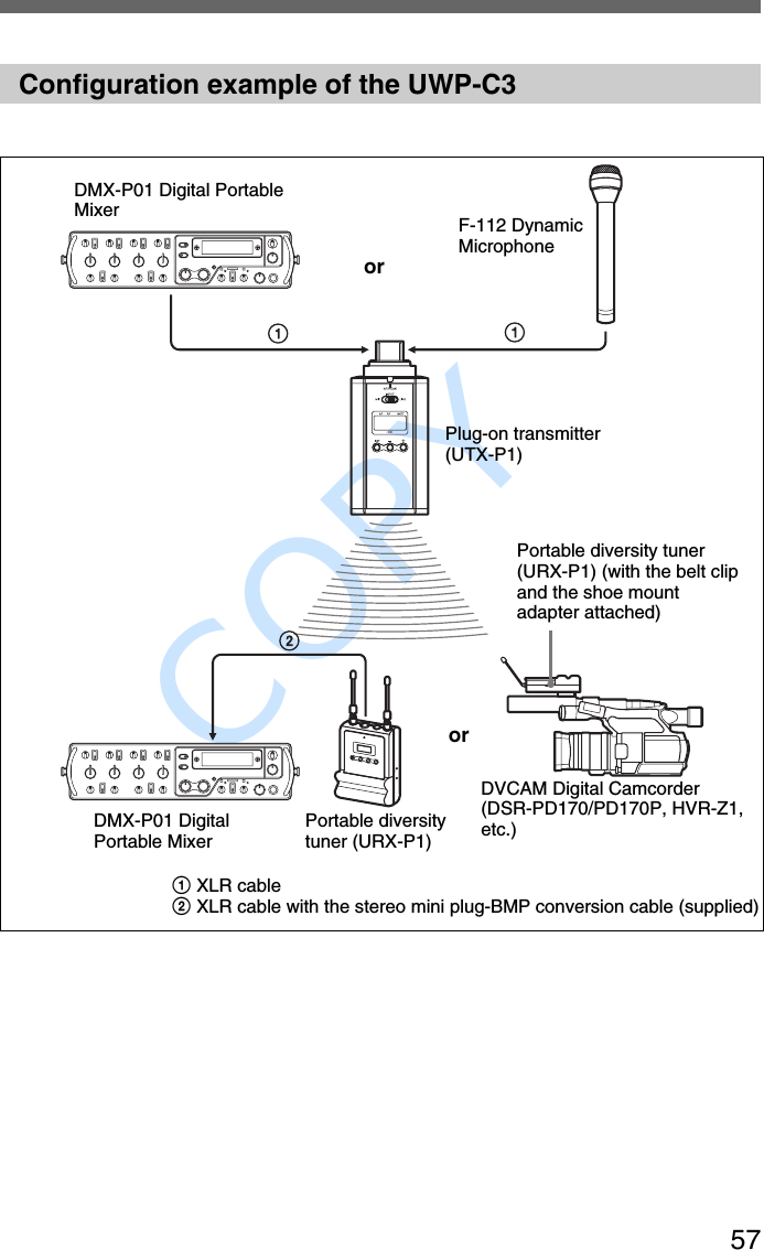
Sony Group UTXP1 UHF Synthesized Transmitter User Manual

Sony Corporation UHF Synthesized Transmitter

User Manual

              COPY 2-347-712-13(1) 2003 Sony CorporationOperating InstructionsBefore operating the unit, please read this manual thoroughly andretain it for future reference.UWP-C1/C2/C3UWP-S1/S2UWP-X1/X2WirelessMicrophone Package
              COPY 2For the AC adapter supplied withUWP-S1/S2Important SafetyInstructions•Read these instructions.•Keep these instructions.•Heed all warnings.•Follow all instructions.•Do not use this apparatus near water.• Clean only with dry cloth.•Do not block any ventilationopenings.  Install in accordance withthe manufacturer’s instructions.•Do not install near any heat sourcessuch as radiators, heat registers,stoves, or other apparatus (includingamplifiers) that produce heat.•Do not defeat the safety purpose ofthe polarized or grounding-type plug.A polarized plug has two blades withone wider than the other.  Agrounding-type plug has two bladesand a third grounding prong.  Thewide blade or the third prong isprovided for your safety.  If theprovided plug does not fit into youroutlet, consult an electrician forreplacement of the obsolete outlet.•Protect the power cord from beingwalked on or pinched particularly atplugs, convenience receptacles, andthe point where they exit from theapparatus.•Only use attachments/accessoriesspecified by the manufacturer.•Use only with the cart, stand, tripod,bracket, or table specified by themanufacturer, or sold with theapparatus.When a cart is used, usecaution when moving thecart/apparatus combinationto avoid injury from tip-over.•Unplug this apparatus duringlightning storms or when unused forlong periods of time.•Refer all servicing to qualifiedservice personnel.  Servicing isrequired when the apparatus hasbeen damaged in any way, such aspower-supply cord or plug isdamaged, liquid has been spilled orobjects have fallen into theapparatus, the apparatus has beenexposed to rain or moisture, does notoperate normally, or has beendropped.WARNINGTo reduce the risk of fire orelectrical shock, do not exposethis apparatus to rain ormoisture.To avoid electrical shock, do notopen the cabinet.  Referservicing to qualified personnelonly.IMPORTANTThe name plate is located on thebottom (AC-911).WARNINGThis unit has no power switch.When installing the unit, incorporate areadily accessible disconnect device inthe fixed wiring, or connect the powercord to socket-outlet which must beprovided near the unit and easilyaccessible.If a fault should occur duringoperation of the unit, operate thedisconnect device to switch the powersupply off, or disconnect the powercord.
              COPY 3This symbol is intended toalert the user to thepresence of uninsulated“dangerous voltage”within the product’senclosure that may be ofsufficient magnitude toconstitute a risk of electricshock to persons.This symbol is intended toalert the user to thepresence of importantoperating andmaintenance (servicing)instructions in theliterature accompanyingthe appliance.CAUTIONTo prevent electric shock, match wideblade of plug to wide slot, fully insert.AVERTISSEMENTAfin de réduire les risquesd’incendie ou d’électrocution, nepas exposer cet appareil à lapluie ou à l’humidité.Afin d’écarter tout risqued’électrocution, garder le coffretfermé. Ne confier l’entretienl’appareil qu’à un technicienqualifié.IMPORTANTLa plaquette signalétique est posée surle dessous de l’appareil (AC-911).AVERTISSEMENTCet appareil ne possède pasd’interrupteur d’alimentation. Lors del’installation de l’appareil, incorporerun dispositif de coupure facilementaccessible dans le câblage fixe oubrancher le cordon d’alimentationdans une prise murale proche del’appareil et facilement accessible.En cas de problème lors dufonctionnement de l’appareil,enclencher le dispositif de coupured’alimentation ou dèbrancher lecordon de la prise.ATTENTIONPour éviter tout choc électrique,ajuster la lame large de la fiche sur lafente large et l’insérer à fond.WARNUNGUm die Gefahr von Brändenoder elektrischen Schlägen zuverringern, darf dieses Gerätnicht Regen oder Feuchtigkeitausgesetzt werden.Um einen elektrischen Schlag zuvermeiden, darf das Gehäusenicht geöffnet werden.Überlassen SieWartungsarbeiten stets nurqualifiziertem Fachpersonal.
              COPY 4WICHTIGAm Boden des Geräts befindet sichdas Typenschild (AC-911).WARNUNGDieses Gerät hat keinen Netzschalter.Beim Einbau des Geräts ist daher imFestkabel ein leicht zugänglicherUnterbrecher einzufügen, oder dasNetzkabel muss mit einer in der Nähedes Geräts befindlichen, leichtzugänglichen Wandsteckdoseverbunden werden.Wenn während des Betriebs eineFunktionsstörung auftritt, ist derUnterbrecher zu betätigen bzw. dasNetzkabel abzuziehen, damit dieStromversorgung zum Gerätunterbrochen wird.ACHTUNGUm die Gefahr elektrischer Schläge zuverhindern, immer den Stecker richtigund vollständig einstecken.ATTENZIONEPer ridurre il rischio di incendi oscosse elettriche, non esporrequesto apparato alla pioggia oall’umidità.Per evitare scosse elettriche,non aprire l’apparecchio.Per le riparazioni, rivolgersi soloa personale qualificato.IMPORTANTELa targhetta con il nome si trova sulfondo (AC-911).AVVERTENZAIl presente apparecchio non è dotato diinterruttore di alimentazione.Quando si installa l’apparecchio,includere nell’impianto fisso undispositivo di disconnessionerapidamente accessibile o collegare ilcavo di alimentazione ad una presa inprossimità dell’apparecchio e che siafacilmente raggiungibile.Nel caso in cui si dovesse verificareuna anomalia durante ilfunzionamento dell’apparecchio, agiresull’interruttore del dispositivo didisconnessione o disconnettere il cavodi alimentazione.ATTENZIONEPer evitare scosse elettriche assicurarsiche la spina sia inserita correttamentee completamente nella presa.ADVERTENCIAPara reducir el riesgo deelectrocución, no exponga esteaparato a la lluvia ni a lahumedad.Para evitar descargas eléctricas,no abra el aparato.Solicite asistencia técnicaúnicamente a personalespecializado.IMPORTANTELa placa de caracteristicas seencuentra en la parte inferior (AC-911).
              COPY 5ADVERTENCIAEsta unidad no tiene interruptoreléctrico.Cuando instale la unidad, incluya undispositivo de desconexión de fácilacceso en el cableado fijo o enchufe elcable eléctrico a un tomacorrientecerca de la unidad y de fácil acceso.Si se produce una falla durante elfuncionamiento de la unidad, utilice eldispositivo de desconexión paradesconectar la electricidad odesenchufe el cable eléctrico.PRECAUCIÓNPara evitar descarga eléctrica, alinee lapata ancha del enchufe en la ranuraancha y enchufe a fondo.
              COPY 6For UTX-B1, UTX-H1, and UTX-P1TransmittersOwner’s RecordThe model and serial numbers arelocated at the rear or on the bottom ofthe unit.  Record the model and serialnumbers in the space provided below.Refer to these numbers whenever youcall upon your Sony dealer regardingthis product.Model No.  _____________________Serial No.   _____________________IMPORTANTThe name plate is located on thebottom and the serial number islocated inside the battery compartment(UTX-P1).IMPORTANTLa plaquette signalétique est posée surle dessous de l’appareil et le numérode série dans le logement des piles(UTX-P1).WICHTIGAm Boden des Geräts befindet sichdas Typenschild und dieSeriennummer befindet sich innen imBatteriefach (UTX-P1).IMPORTANTELa targhetta con il nome si trova sulfondo e il numero di serie si trovaall’interno del vano pile (UTX-P1).IMPORTANTELa placa de caracteristicas seencuentra en la parte inferior y elnúmero de serie está en el interior delcompartimiento de pilas (UTX-P1).Notice for customers in theU.S.A.Use of Sony wireless devices isregulated by the FederalCommunications Commission asdescribed in Part 74 subpart H of theFCC regulations and users authorizedthereby are required to obtain anappropriate license.You are cautioned that any changes ormodifications not expressly approvedin this manual could void yourauthority to operate this equipment.IMPORTANT NOTE:  To complywith the FCC RF exposure compliancerequirements, no change to theantenna or the device is permitted.Any change to the antenna or thedevice could result in the deviceexceeding the RF exposurerequirements and void user’s authorityto operate this device.This device complies with FCCradiation exposure limits set forth foruncontrolled equipment and meets theFCC radio frequency (RF) ExposureGuidelines in Supplement C toOET65. This device has very lowlevels of RF energy that it is deemedto comply without testing of specificabsorption ratio (SAR).
              COPY 7Notice for customers in Canada:Use of Sony wireless devices isregulated by the Industry Canada asdescribed in their Radio StandardSpecification RSS-123.A licence is normally required.  Thelocal district office of Industry Canadashould therefore be contacted.  Whenthe operation of the device is withinthe broadcast band, the licence isissued on no-interference, no-protection basis with respect tobroadcast signals.Operation of this device is subject tothe following two conditions: (1) thisdevice may not cause interference, and(2) this device must accept anyinterference, including interferencethat may cause undesired operation ofthe device.The term “IC:” before the radiocertification number only signifies thatIndustry Canada technicalspecifications were met.Remarque à l’intention desutilisateurs au Canada:L’usage des appareils sans fil Sony estréglementé par l’Industrie Canadacomme décrit dans leur Cahier desNormes Radioélectriques CNR-123.Une licence est normalement requise.Le bureau de l’Industrie Canada doitêtre contacté. Lorsque lefonctionnement de l’appareil respecteles limites de la bande deradiodiffusion, la licence est accordéesur la base d’une non-interférence,non-protection pour les signaux deradiodiffusion.L’utilisation de cet appareil estsoumise aux deux conditionssuivantes:  (1) cet appareil ne peutcauser d’interférences, et (2) cetappareil doit accepter toutes lesinterférences, y compris lesinterférences capables de provoquerun fonctionnement non souhaité del’appareil.L’expression <<IC:>> avant lenuméro d’homologation/enregistrement signifie seulement queles spécifications techniques del’Industrie Canada ont été respectées.Für Kunden in Deutshland (UTX-B1/H1/P1)Entsorgungshinweis:  Bitte werfen Sienur entladene Batterien in dieSammelboxen beim Handel oder denKommunen. Entladen sind Batterienin der Regel dann, wenn das Gerätabschaltet und signalisiert “Batterieleer” oder nach längererGebrauchsdauer der Batterien “nichtmehr einwandfrei funktioniert”. Umsicherzugehen, kleben Sie dieBatteriepole z.B. mit einemKlebestreifen ab oder geben Sie dieBatterien einzeln in einenPlastikbeutel.Voor de Klanten in Nederland(UTX-B1/H1/P1)Gooi de batterij niet wegmaar lever deze in als kleinchemisch afval (KCA).
              COPY 8Notice for customers in EuropeNotification aux clientseuropéensHinweis für die Kunden inEuropaAvvertenza per gli utilizzatori inEuropaAviso para los clientes deEuropaNota para utilizadores daEuropaMededeling voor de klanten inEuropaAtt observera för kunder iEuropaMeddelelse til kunderne iEuropaHuomautus Euroopassa asuvilleasiakkaillemmeU.K. 854.125 - 862 MHzGermany 790 - 814 MHzNorway 800 - 820 MHzLuxembourg 800 - 830 MHz,854.125 - 862 MHzBelgium 854.125 - 862 MHzDenmark 800.100 - 819.900MHzFrance 798 - 830 MHzItaly 800 - 820 MHzSweden 800 - 820 MHzSwitzerland 800 - 820 MHzFinland 800.100 - 819.900MHzIceland 800 - 814 MHzHereby, Sony Corporation declaresthat this UTX-B1/UTX-H1/UTX-P1 isin compliance with the essentialrequirements and other relevantprovisions of Directive 1999/5/EC.For details, please access thefollowing URL:http://www.compliance.sony.de/Note:In some countries additionalfrequency bands may be used with theagreement of the national authority.Sony Corporation déclare par cesprésentes que le UTX-B1/UTX-H1/UTX-P1 est conforme aux exigencesessentielles et aux dispositionsapplicables de la Directive 1999/5/CE.Pour les détails, accédez à l’URLsuivante:http://www.compliance.sony.de/Remarque:Dans certains pays, des bandes defréquences additionnelles pourrontêtre utilisées avec l’accord desautorités nationales.Hiermit erklärt Sony Corporation,dass die vorliegende Einheit UTX-B1/UTX-H1/UTX-P1 den wesentlichenAnforderungen und anderenrelevanten Bestimmungen derRichtlinie 1999/5/EC entspricht. FürEinzelheiten siehe folgende URL:http://www.compliance.sony.de/Hinweis:In manchen Ländern ist mitGenehmigung der zuständigenBehörden u.U. die Nutzung weitererFrequenzbänder möglich.
              COPY 9Con questo Sony Corporation dichiarache questo UTX-B1/UTX-H1/UTX-P1 è in conformità con i requisitiessenziali e altri provvedimenti inmateria della Direttiva 1999/5/CE. Perdettagli, si prega di accedere allaseguente URL:http://www.compliance.sony.de/Nota:In alcuni paesi possono essere usatebande di frequenza supplementari conil permesso delle autorità nazionali.Sony Corporation declara aquí queeste modelo, UTX-B1/UTX-H1/UTX-P1, cumple los requisitos esenciales ydemás provisiones pertinentes de laDirectiva 1999/5/EC.Con respecto alos detalles, realice el acceso a laURL:http://www.compliance.sony.de/Nota:En algunos países pueden utilizarsebandas de frecuencia adicionales deacuerdo con la autoridad nacional.A Sony Corporation declara que omodelo UTX-B1/UTX-H1/UTX-P1está em conformidade com asexigências essenciais e outrasprovisões pertinentes da Directiva1999/5/EC. Mais informações nesteendereço da Internet:http://www.compliance.sony.de/Obs.:Em alguns países uma faixa adicionalde frequências pode ser utilizada comautorização do governo nacional.Sony Corporation verklaart hierbij datde UTX-B1/UTX-H1/UTX-P1voldoet aan de primaire vereisten enandere relevante voorschriften van deEuropese Bepaling 1999/5/EC. Naderebijzonderheden vindt u op de volgendewebsite:http://www.compliance.sony.de/Opmerking:In bepaalde landen kan er gebruikgemaakt worden van aanvullendefrequentiebanden, mits toegestaandoor de nationale instanties.Sony Corporation förkunnar härmedatt denna UTX-B1/UTX-H1/UTX-P1uppfyller de huvudsakliga kraven ochandra relevanta villkor i direktivet1999/5/EC. Se följande URL förnärmare detaljer:http://www.compliance.sony.de/Observera:I vissa länder kan det hända attytterligare frekvensband används efteröverenskommelse med det landetsmyndigheter.Sony Corporation erklærer herved, atdenne UTX-B1/UTX-H1/UTX-P1 er ioverensstemmelse med de essentiellekrav og andre relevante bestemmelseri direktiv 1999/5/EC. Åbn venligst denfølgende URL angående detaljer:http://www.compliance.sony.de/Bemærk:I nogle land kan yderligerefrekvensbånd blive anvendt med denationale autoriteters samtykke.
              COPY 10Sony Corporation julistaa täten, ettätämä UTX-B1/UTX-H1/UTX-P1vastaa direktiivin 1999/5/EColennaisia vaatimuksia ja muitaasiaankuuluvia määräyksiä. Katsotarkemmat tiedot osoitteesta:http://www.compliance.sony.de/Huom!Joissakin maissa lisätaajuuskaistojavoidaan käyttää viranomaistensuostumuksella.Note for customers inSwitzerland:Before use, a request of concession fora wireless microphone (FrequencyClass 3) has to be submitted toBakom.Note concernant les utilisateursen Suisse:Une demande de concession demicrophone sans fil (fréquence classe3) doit être présentée au Bakom avantd’utiliser l’appareil.Hinweis für Kunden in derSchweiz:Vor Inbetriebnahme ist eineKonzessionsanforderung für eindrahtloses Mikrofon (Frequenzklasse3) bei Bakom einzureichen.Note for customers in Finland:To own and use, it is necessary toobtain an individual licence of theTelecommunications AdministrationCenter.Huomautus Suomessa asuvilleasiakkaillemmeOmitusta ja käyttöä varten on tarpeenhankkia henkilökohtainen lupatietoliikennehallintokeskuksesta.Note for customers inLuxembourg:Before any use of an equipment, thefrequencies required have to be, ifnecessary according to the regulationsin force, assigned prior to usage by the“ILT”.Remarque pour les clients auLuxembourg:Avant tout emploi de cet appareil, sinécessaire conformément à laréglementation en vigueur, lesfréquences requises doivent êtreassignées, avant l’usage par le “ILT”.Hinweis für Kunden inLuxemburg:Vor Inbetriebnahme eines Gerätsmüssen die Frequenzengegebenenfalls nach den geltendenVorschriften vor dem Gebrauch vonder „ILT“ zugewiesen werden.
              COPY 11Note for customers in Italy:The use of this product within Italy issubject to article 334 of the Postal andTelecommunications regulations.Nota per i clienti in Italia:L’uso del prodotto sul territorioitaliano è soggetto alleregolamentazioni del Codice Postale edelle Telecomunicazioni art. 334.Note for customers in Belgium:Using the UTX-B1/UTX-H1 with 30mW RF output power is not allowed.Be sure to set the RF output power to5 mW.The UTX-P1’s RF output power is 50mW. Using the UTX-P1 in Belgium isnot allowed.Remarque concernant lesutilisateurs en Belgique:L’emploi du UTX-B1/UTX-H1 avecune puissance de sortie RF 30 mWn’est pas autorisé. Bien régler lapuissance de sortie RF à 5 mW.La puissance de sortie RF du UTX-P1est 50 mW. L’emploi du UTX-P1n’est pas autorisé en Belgique.Hinweis für Kunden in Belgien:Verwendung des UTX-B1/UTX-H1mit 30 mW HF-Ausgangsleistung istnicht zulässig.  Immer die HF-Ausgangsleistung auf 5 mWeinstellen.Die Ausgangsleistung des UTX-P1beträgt 50 mW. Verwendung desUTX-P1 in Belgien ist nicht zulässig.Mededeling voor de klanten inBelgië:Het is niet toegestaan de UTX-B1/UTX-H1 te gebruiken met een RFuitgangsvermogen van 30 mW. Zorgdat het RF uitgangsvermogen isingesteld op 5 mW.Het RF uitgangsvermogen van deUTX-P1 is 50 mW. De UTX-P1 magniet in België worden gebruikt.Note for customers in Norway:Using this transmitter requires theIndividual License.Hinweis für Kunden inDeutschland:Vor Inbetriebnahme muss bei derzuständigen Außenstelle derRegulierungsbehörde (Reg TP) eineKanalzuweisung beantragt werden.Note for customers in Iceland:Using this transmitter requires theIndividual License.Note for customers in Sweden:Using this transmitter requires theIndividual License.Att observera för kunder iSverige:För att använda denna sändare krävsIndividuell Licens.
              COPY 12For URX-P1, URX-M1, and URX-R1TunersOwner’s RecordThe model and serial numbers arelocated at the rear or on the side of theunit.  Record the model and serialnumbers in the space provided below.Refer to these numbers whenever youcall upon your Sony dealer regardingthis product.Model No.  _____________________Serial No.   _____________________Notice for customers in theU.S.A.You are cautioned that any changes ormodifications not expressly approvedin this manual could void yourauthority to operate this equipment.Declaration of ConformityTrade Name: SONYModel No.: URX-P1URX-M1URX-R1Responsible Party:Sony ElectronicsInc.Address: 16450 W.Bernardo Dr, SanDiego, CA. 92127U.S.A.Telephone No.: 858-942-2230This device complies with Part 15of the FCC Rules. Operation issubject to the following twoconditions:(1) This device may not causeharmful interference, and(2) this device must accept anyinterference received, includinginterference that may causeundesired operation.If you have any questions about thisproduct, you may call:Sony Customer Information ServiceCenter1-800-222-7669 or http://www.sony.com/Notice for customers in Canada:Use of Sony wireless devices isregulated by the Industry Canada asdescribed in their Radio StandardSpecification RSS-123.A licence is normally required.  Thelocal district office of Industry Canadashould therefore be contacted.  Whenthe operation of the device is withinthe broadcast band, the licence isissued on no-interference, no-protection basis with respect tobroadcast signals.Operation of this device is subject tothe following two conditions: (1) thisdevice may not cause interference, and(2) this device must accept anyinterference, including interferencethat may cause undesired operation ofthe device.The term “IC:” before the radiocertification number only signifies thatIndustry Canada technicalspecifications were met.Remarque à l’intention desutilisateurs au Canada:L’usage des appareils sans fil Sony estréglementé par l’Industrie Canadacomme décrit dans leur Cahier desNormes Radioélectriques CNR-123.Une licence est normalement requise.Le bureau de l’Industrie Canada doitêtre contacté. Lorsque lefonctionnement de l’appareil respecte
              COPY 13les limites de la bande deradiodiffusion, la licence est accordéesur la base d’une non-interférence,non-protection pour les signaux deradiodiffusion.L’utilisation de cet appareil estsoumise aux deux conditionssuivantes:  (1) cet appareil ne peutcauser d’interférences, et (2) cetappareil doit accepter toutes lesinterférences, y compris lesinterférences capables de provoquerun fonctionnement non souhaité del’appareil.L’expression <<IC:>> avant lenuméro d’homologation/enregistrement signifie seulement queles spécifications techniques del’Industrie Canada ont été respectées.Für Kunden in Deutshland (URX-P1)Entsorgungshinweis:  Bitte werfen Sienur entladene Batterien in dieSammelboxen beim Handel oder denKommunen. Entladen sind Batterienin der Regel dann, wenn das Gerätabschaltet und signalisiert “Batterieleer” oder nach längererGebrauchsdauer der Batterien “nichtmehr einwandfrei funktioniert”. Umsicherzugehen, kleben Sie dieBatteriepole z.B. mit einemKlebestreifen ab oder geben Sie dieBatterien einzeln in einenPlastikbeutel.Voor de Klanten in Nederland(URX-P1)Gooi de batterij niet wegmaar lever deze in als kleinchemisch afval (KCA).Notice for customers in EuropeNotification aux clientseuropéensHinweis für die Kunden inEuropaAvvertenza per gli utilizzatori inEuropaAviso para los clientes deEuropaNota para utilizadores daEuropaMededeling voor de klanten inEuropaAtt observera för kunder iEuropaMeddelelse til kunderne iEuropaHuomautus Euroopassa asuvilleasiakkaillemmeU.K. 854.125 - 862 MHzGermany 790 - 814 MHzNorway 800 - 820 MHzLuxembourg 800 - 830 MHz,854.125 - 862 MHzBelgium 854.125 - 862 MHzDenmark 800.100 - 819.900MHzFrance 798 - 830 MHzItaly 800 - 820 MHzSweden 800 - 820 MHzSwitzerland 800 - 820 MHzFinland 800.100 - 819.900MHzIceland 800 - 814 MHzHereby, Sony Corporation declaresthat this URX-P1/M1/R1 is incompliance with the essential
              COPY 14requirements and other relevantprovisions of Directive 1999/5/EC.For details, please access thefollowing URL:http://www.compliance.sony.de/Sony Corporation déclare par cesprésentes que le URX-P1/M1/R1 estconforme aux exigences essentielles etaux dispositions applicables de laDirective 1999/5/CE. Pour les détails,accédez à l’URL suivante:http://www.compliance.sony.de/Hiermit erklärt Sony Corporation,dass die vorliegende Einheit URX-P1/M1/R1 den wesentlichenAnforderungen und anderenrelevanten Bestimmungen derRichtlinie 1999/5/EC entspricht. FürEinzelheiten siehe folgende URL:http://www.compliance.sony.de/Con questo Sony Corporation dichiarache questo URX-P1/M1/R1 è inconformità con i requisiti essenziali ealtri provvedimenti in materia dellaDirettiva 1999/5/CE. Per dettagli, siprega di accedere alla seguente URL:http://www.compliance.sony.de/Sony Corporation declara aquí queeste modelo, URX-P1/M1/R1 cumplelos requisitos esenciales y demásprovisiones pertinentes de la Directiva1999/5/EC. Con respecto a losdetalles, realice el acceso a la URL:http://www.compliance.sony.de/A Sony Corporation declara pelapresente que o modelo URX-P1/M1/R1 está em conformidade com asexigências essenciais e outrasprovisões pertinentes da Directiva1999/5/EC. Mais informações nesteendereço da Internet:http://www.compliance.sony.de/Sony Corportion verklaart hierbij datde URX-P1/M1/R1 voldoet aan deprimaire vereisten en andere relevantevoorschriften van de EuropeseBepaling 1999/5/EC. Naderebijzonderheden vindt u op de volgendewebsite:http://www.compliance.sony.de/Sony Corporation förkunnar härmedatt denna URX-P1/M1/R1 uppfyllerde huvudsakliga kraven och andrarelevanta villkor i direktivet 1999/5/EC. Se följande URL för närmaredetaljer:http://www.compliance.sony.de/Sony Corporation erklærer herved, atdenne URX-P1/M1/R1 er ioverensstemmelse med de essentiellekrav og andre relevante bestemmelseri direktiv 1999/5/EC. Åbn venligst denfølgende URL angående detaljer:http://www.compliance.sony.de/Sony Corporation julistaa täten, ettätämä URX-P1/M1/R1 vastaadirektiivin 1999/5/EC olennaisiavaatimuksia ja muita asiaankuuluviamääräyksiä. Katso tarkemmat tiedotosoitteesta:http://www.compliance.sony.de/
              COPY 15Para os clientes no BrasilO uso dos modulos UWP-C1, S1, X1 e UWP-C2, S2, X2 atende às normas eresoluções da Anatel, conforme homologação a seguir:
              COPY Table of Contents16Table of ContentsConfiguration of thePackages ........................... 17UWP-C1................................... 17UWP-C2................................... 18UWP-C3................................... 19UWP-S1 ................................... 20UWP-S2 ................................... 21UWP-X1 .................................. 22UWP-X2 .................................. 23Features .................................. 24Using the CD-ROM Manual.... 26CD-ROM systemrequirements............................. 26Preparations ............................. 26To read the operatinginstructions ............................... 26To read the Sony WirelessMicrophone System FrequencyList ........................................... 26Precautions............................. 28Parts Identification ................. 29Body-pack transmitter(UTX-B1)................................. 29Hand-held microphone(UTX-H1) ................................ 30Plug-on transmitter(UTX-P1) ................................. 31Portable diversity tuner(URX-P1) ................................. 33Half-rack size diversity tuner(URX-R1) ................................ 35Diversity tuner module(URX-M1) ............................... 36Power Supply ......................... 38Inserting the batteries ............... 38Attachment and InstallationProcedures ........................ 41Attaching the suppliedaccessories to the body-packtransmitter (UTX-B1) .............. 41Attaching the supplied accessoryto the hand-held microphone(UTX-H1) ................................ 42Inserting the plug-on transmitter(UTX-P1) into the supplied softcase........................................... 42Attaching optional accessoryto the plug-on transmitter(UTX-P1) ................................. 43Attaching the suppliedaccessories to the portablediversity tuner (URX-P1)......... 43Installing the diversity tunermodule (URX-M1) .................. 44Settings ................................... 47Setting the transmissionchannel ..................................... 47Setting the reception channel ... 48Detecting and selecting theavailable channels automatically(diversity tuner module(URX-M1) only) ...................... 50Setting the attenuation levelof the audio input ..................... 50Resetting the accumulatedbattery use time indication ....... 51Setting the RF output level ...... 52Setting the monitor level(portable diversity tuner(URX-P1) only) ....................... 52Operation ................................ 53System Configurations .......... 54Configuration examples of theUWP-C1/C2/S1/S2/X1/X2 ...... 54Configuration example of theUWP-C3................................... 57Error Messages ...................... 58Troubleshooting ..................... 59Specifications ......................... 61
              COPY 17Configuration of the PackagesThis operation manual is for the UWP-C1/C2/C3/S1/S2/X1/X2wireless microphone packages. The contents of each packageare described below.UWP-C1The UWP-C1 consists of a body-pack transmitter (UTX-B1)and a portable diversity tuner (URX-P1). When used inconjunction with a compact camcorder, the UWP-C1 makes amobile system for ENG (Electronic News Gathering) or EFP(Electronic Field Production) purposes.Body-pack transmitter(UTX-B1) (1) Portable diversity tuner(URX-P1) (1)Supplied accessories•Omni-directional lavalier microphone(1) •Wind screen (1)•XLR-BMP conversion cable (1)•Holder clip (1)•Shoe mount adapter (1) •Belt clip (2)•Microphone stand adapter (1) • Operation manual (1)•CD-ROM (1) (for U62, U66, CE62, and CE67models)•Sony Wireless Microphone System FrequencyList (1) (for AU66 and CE67 models)•Warranty card (1) (for U62 and U66 models)•Stereo mini plug-BMP conversioncable (1)
              COPY Configuration of the Packages18UWP-C2The UWP-C2 consists of a hand-held microphone (UTX-H1)and a portable diversity tuner (URX-P1). When used inconjunction with a compact camcorder, the UWP-C2 makes amobile system for ENG (Electronic News Gathering) or EFP(Electronic Field Production) purposes.Hand-held microphone(UTX-H1) (1) Portable diversity tuner(URX-P1) (1)Supplied accessories•Microphone holder (1) • Belt clip (1)•Shoe mount adapter (1) •XLR-BMP conversion cable (1)•Microphone stand adapter (1) •Operation manual (1)•CD-ROM (1) (for U62, U66, CE62, and CE67 models)•Sony Wireless Microphone System Frequency List (1)(for AU66 and CE67 models)•Warranty card (1) (for CE62 and U66 models)•Stereo mini plug-BMP conversion cable (1)
              COPY 19UWP-C3The UWP-C3 consists of a plug-on transmitter (UTX-P1) and aportable diversity tuner (URX-P1). When used in conjunctionwith a compact camcorder, the UWP-C3 makes a mobilesystem for ENG (Electronic News Gathering) or EFP(Electronic Field Production) purposes.Plug-on transmitter(UTX-P1) (1) Portable diversity tuner(URX-P1) (1)Supplied accessories•Soft case (1) • Belt clip (1)•Shoe mount adapter (1) •XLR-BMP conversion cable (1)•Operation manual (1)•CD-ROM (1) (for U62, U66, CE62, and CE67 models)•Sony Wireless Microphone System Frequency List (1) (for CE67 model)•Warranty card (1) (for U62 and U66 models)•Stereo mini plug-BMP conversion cable (1)
              COPY Configuration of the Packages20UWP-S1The UWP-S1 consists of a body-pack transmitter (UTX-B1)and a half-rack size diversity tuner (URX-R1). The UWP-S1 issuitable for constructing a wireless system for AVpresentations.Body-pack transmitter(UTX-B1) (1) Half-rack size diversity tuner(URX-R1) (1)Supplied accessories•Unidirectional lavaliermicrophone (1) •Wind screen (1) •Holder clip (1)•AC adapter (1) • Belt clip (1) •Operation manual (1)•CD-ROM (1) (for U62, U66,CE62, and CE67 models)•Sony Wireless MicrophoneSystem Frequency List (1)(for AU66 and CE67 models)•Warranty card (1) (for U62and U66 models)–AC-S906T (for U62 and U66models)–AC-S906 (for CE62 model)–AC-S911 (for CE67 model)–AC-X1 (for AU66 model)
              COPY 21UWP-S2The UWP-S2 consists of a hand-held microphone (UTX-H1)and a half-rack size diversity tuner (URX-R1). The UWP-S2 issuitable for constructing a wireless system for AVpresentations.Hand-held microphone(UTX-H1) (1) Half-rack size diversity tuner(URX-R1) (1)Supplied accessories•Microphone holder (1) • AC adapter (1)•Operation manual (1)•CD-ROM (1) (for U62, U66, CE62, and CE67 models)•Sony Wireless Microphone System Frequency List (1) (for AU66 and CE67 models)•Warranty card (1) (for U62 and U66 models)–AC-S906T (for U62 and U66 models)–AC-S906 (for CE62 model)–AC-S911 (for CE67 model)–AC-X1 (for AU66 model)
              COPY Configuration of the Packages22UWP-X1The UWP-X1 consists of a body-pack transmitter (UTX-B1)and a diversity tuner module (URX-M1). By installing the tunermodule into a tuner base unit or a powered mixer, the systemconstruction to meet the desired purpose of use and requiredsystem scale becomes possible.Body-pack transmitter(UTX-B1) (1) Diversity tuner module(URX-M1) (1)Supplied accessories•Unidirectional lavaliermicrophone (1) •Wind screen (1) • Holder clip (1)•Belt clip (1) •Operation manual (1)•CD-ROM (1) (for U62, U66, CE62, and CE67 models)•Sony Wireless Microphone System Frequency List (1)(for AU66 and CE67 models)•Warranty card (1) (for U62 and U66 models)
              COPY 23UWP-X2The UWP-X2 consists of a hand-held microphone (UTX-H1)and a diversity tuner module (URX-M1) . By installing thetuner module into a tuner base unit or a powered mixer, thesystem construction to meet the desired purpose of use andrequired system scale becomes possible.Hand-held microphone(UTX-H1) (1) Diversity tuner module(URX-M1) (1)Supplied accessories•Microphone holder (1) •Operation manual (1)•CD-ROM (1) (for U62, U66, CE62, and CE67 models)•Sony Wireless Microphone System Frequency List (1)(for AU66 and CE67 models)•Warranty card (1) (for U62 and U66 models)
              COPY Features24FeaturesEach of the UWP-C1/C2/C3/S1/S2/X1/X2 wireless microphone packages(referred to as the UWP serieshereafter) combines a transmitter(body-pack transmitter (UTX-B1),hand-held microphone (UTX-H1), orplug-on transmitter (UTX-P1)) and areceiver (portable diversity tuner(URX-P1), half-rack size diversitytuner (URX-R1), or diversity tunermodule (URX-M1)). The UWP seriescan be used with a compact camcorderfor ENG (Electronic News Gathering)purposes, and with a powered mixerfor AV presentations or as a PA(public address) system.NoteThe UWP series is not compatiblewith conventional WRT seriestransmitters, WRR series tuners, orWRU series tuner units.The features of each package aredescribed below.UWP-C1Body-pack transmitter (UTX-B1)This is a small and lightweighttransmitter with a crystal-controlledPLL (phase lock loop) synthesizedsystem and a BMP-type microphoneinput connector.  The RF power outputcan be set at 30 mW or at 5 mW.Portable diversity tuner(URX-P1)This tuner employs a space diversitysystem with little signal dropout andtwo angle-adjustable antennas. Itcomes with an adapter for mountingthe tuner on the compact camcorder(DSR-PD170/PD170P, HVR-Z1, etc.).UWP-C2Hand-held microphone (UTX-H1)This microphone is equipped with abuilt-in antenna and a unidirectionaldynamic microphone unit. The RFpower output can be set at 30 mW orat 5 mW.Portable diversity tuner(URX-P1)This tuner employs a space diversitysystem with little signal dropout andtwo angle-adjustable antennas. Itcomes with an adapter for mountingthe tuner on the compact camcorder(DSR-PD170/PD170P, HVR-Z1, etc.).UWP-C3Plug-on transmitter (UTX-P1)This is a small and lightweight plug-on transmitter with a crystal-controlled PLL (phase lock loop)synthesized system and an XLR-typemicrophone input connector. The RFpower output is set at 50 mW.
              COPY 25Portable diversity tuner (URX-P1)This tuner employs a space diversitysystem with little signal dropout andtwo angle-adjustable antennas. Itcomes with an adapter for mountingthe tuner on the compact camcorder(DSR-PD170/PD170P, HVR-Z1, etc.).UWP-S1Body-pack transmitter (UTX-B1)This is a small and lightweighttransmitter with a crystal-controlledPLL (phase lock loop) synthesizedsystem and a BMP-type microphoneinput connector.  The RF power outputcan be set at 30 mW or at 5 mW.Half-rack size diversity tuner(URX-R1)This tuner employs a space diversitysystem with little signal dropout andtwo angle-adjustable antennas. Itcomes with two types of audioconnectors (1/4-inch jack and XLRtype) on the rear panel.UWP-S2Hand-held microphone (UTX-H1)This microphone is equipped with abuilt-in antenna and a unidirectionaldynamic microphone unit. The RFpower output can be set at 30 mW orat 5 mW.Half-rack size diversity tuner(URX-R1)This tuner employs a space diversitysystem with little signal dropout andtwo angle-adjustable antennas. Itcomes with two types of audioconnectors (1/4-inch jack and XLRtype) on the rear panel.UWP-X1Body-pack transmitter (UTX-B1)This is a small and lightweighttransmitter with a crystal-controlledPLL (phase lock loop) synthesizedsystem and a BMP-type microphoneinput connector.  The RF power outputcan be set at 30 mW or at 5 mW.Diversity tuner module(URX-M1)This tuner module can be incorporatedinto the MB-806A Tuner Base Unit orSRP-X500P/X700P Powered Mixer.UWP-X2Hand-held microphone (UTX-H1)This microphone is equipped with abuilt-in antenna and a unidirectionaldynamic microphone unit. The RFpower output can be set at 30 mW orat 5 mW.Diversity tuner module(URX-M1)This tuner module can be incorporatedinto the MB-806A Tuner Base Unit orSRP-X500P/X700P Powered Mixer.
              COPY Using the CD-ROM Manual26Using the CD-ROM ManualThe supplied CD-ROM includesoperating instructions for the UWPseries wireless microphone packages(English, Japanese, French, German,Italian, and Spanish versions) andSony Wireless Microphone SystemFrequency Lists (English, French,German, and Spanish versions).CD-ROM systemrequirementsThe following are required to accessthe supplied CD-ROM disc.•Computer: PC with Intel PentiumCPU— Installed memory: 64 MB or more—CD-ROM drive:  ×8 or faster•Monitor: Monitor supportingresolution of 800 × 600 or higher•Operating system: MicrosoftWindows XP Professional orWindows XP Home EditionWhen these requirements are not met,access to the CD-ROM disc may beslow, or not possible at all.PreparationsOne of the following programs mustbe installed on your computer in orderto use the operating instructionscontained on the CD-ROM disc.•Adobe Acrobat Reader Version 4.0or higher•Adobe Reader Version 6.0 or higherNoteIf Adobe Reader is not installed, youcan download it from the followingURL:http://www.adobe.com/To read the operatinginstructionsTo read the operating instructionscontained in the CD-ROM disc, do thefollowing.1Insert the CD-ROM disc in yourCD-ROM drive.A cover page appearsautomatically in your browser.If it does not appear automaticallyin the browser, open MyComputer, access the CD-ROMdrive, and double-click theindex.htm file.2Select and click the operatinginstructions that you want to read.A PDF file of the operatinginstructions opens.To read the SonyWireless MicrophoneSystem Frequency ListThe frequency lists for U62 and U66models (for the U.S.A.) and CE62 andCE67 models (for Europe) arecontained in the CD-ROM disc.  Toread the frequency lists, do thefollowing.
              COPY 271Insert the CD-ROM disc in yourCD-ROM drive.A cover page appearsautomatically in your browser.2Select and click the frequency listthat you want to read.A PDF file of the frequency listopens.NoteIf you lose the CD-ROM disc orbecome unable to read its content, youcan purchase a new CD-ROM disc toreplace one that has been lost ordamaged. Contact your Sony servicerepresentative.Trademarks•Intel and Pentium are registeredtrademarks of Intel Corporation or itssubsidiaries in the United States andother countries.•Microsoft and Windows areregistered trademarks of MicrosoftCorporation in the United States and/or other countries.•Adobe, Acrobat, and Adobe Readerare trademarks of Adobe SystemsIncorporated in the United Statesand/or other countries.
              COPY Precautions28Precautions•The UWP series product must beused within a temperature range of0°C to 40°C (32°F to 104°F).•Operating the UWP series productnear electrical equipment (motors,transformers, or dimmers) may causeit to be affected by electromagneticinduction. Keep the UWP seriesproduct as far from such equipmentas possible.•The presence of the lightingequipment may produce electricalinterference over the entirefrequency range. Position the UWPseries product so that interference isminimized.•To avoid degradation of the signal-to-noise ratio, do not use the UWPseries product in noisy places or inlocations subject to vibration, such asthe following:—near electrical equipment, such asmotors, transformers or dimmers—near air conditioning equipmentor places subject to direct airflow from an air conditioner—near public address loudspeakers—where adjacent equipment mightknock against the tunerKeep the UWP series product as farfrom such equipment as possible oruse buffering material.•Clean the surface and the connectorsof the UWP series product with adry, soft cloth. Never use thinner,benzene, alcohol or any otherchemicals, since these may mar thefinish.To prevent electromagneticinterference from portablecommunication devicesThe use of portable telephones andother communication devices nearthe UWP series product may resultin malfunction and interference withaudio signals. It is recommendedthat portable communicationdevices near the UWP seriesproduct be turned off.
              COPY 29TransmissionchannelTransmissionfrequencyAttenuationlevel of theinput signalAccumulatedbattery usetimePresstheSETbutton.The channel/frequency indications forU66 model are shown.Parts IdentificationBody-pack transmitter(UTX-B1)1  Antenna2  Audio input connectorConnect the supplied lavaliermicrophone here.3  Power indicatorLights up red when the transmitter istuned on.4  Display sectionA AF (audio frequency) indicationAppears whenever the input audiosignal is stronger than the referencelevel.B RF (radio frequency) indicationAppears during signal transmissionfrom the antenna.C RF (radio frequency) levelindicationShows the RF output level setting.For details, see “Setting the RF outputlevel” on page 52.D BATT (battery) indicationShows the battery condition.For details, see “Power Supply” onpage 38.E CH (channel) indicationShows the transmission channel. Eachtime you press the SET button intransmission mode, the channelindication changes as follows.For details, see “Settings” on page47.ABDEAF RFCHBATTCHLThe E channel indication forU66 model is shown.
              COPY Parts Identification305  + (+ selection) / – (– selection/reset) buttonsPress these buttons to set thetransmission channel, frequency, orattenuation level of the input signal.The “–” button resets the accumulatedbattery use time to “00:00”.6  Battery compartmentAccommodates two LR6 (size AA)alkaline batteries.For details on how to insert thebatteries, see “Power Supply” onpage 38.7  SET buttonPress to change and enter displayparameters.For details, see “Settings” on page47.8  POWER switchTurns the power of the transmitter ONor OFF.Hand-held microphone(UTX-H1)1  Power indicatorLights up red when the microphone isturned on.2  POWER switchTurns the power of the microphoneON or OFF.3  Battery compartmentAccommodates two LR6 (size AA)alkaline batteries.For details on how to insert thebatteries, see “Power Supply” onpage 38.4  Display sectionA AF (audio frequency) indicationAppears whenever the input audiosignal is stronger than the referencelevel.B RF (radio frequency) indicationAppears during signal transmissionfrom the antenna.C RF (radio frequency) levelindicationShows the RF output level setting.For details, see “Setting the RF outputlevel” on page 52.ABDECHLThe E channel indication forU66 model is shown.The rearside of thebatterycompartment
              COPY 31D BATT (battery) indicationShows the battery condition.For details, see “Power Supply” onpage 38.E CH (channel) indicationShows the transmission channel. Eachtime you press the SET button, thechannel indication changes as follows.For details, see “Settings” on page47.5  + (+ selection) / – (– selection/reset) buttonsPress these buttons to set thetransmission channel, frequency, orattenuation level of the input signal.The “–” button resets the accumulatedbattery use time to “00:00”.6  SET buttonPress to change display parameters.For details, see “Settings” on page47.TransmissionchannelTransmissionfrequencyAttenuationlevel of theinput signalAccumulatedbattery usetimePresstheSETbutton.The channel/frequency indications forU66 model are shown.Plug-on transmitter(UTX-P1)1  Audio input connector (XLRtype)Connect a microphone or a line outputconnector of an audio mixer, etc.6Front sideBottom side
              COPY Parts Identification322  AF/PEAK (audio frequency/peak) level indicatorThe color indicates the strength of  theaudio input signal.On in red:  Audio input level is –40dBV or more (when the INPUTselector is set to MIC) or +8 dBVor more (when the INPUTselector is set to LINE).On in green:  Audio input level is–60 dBV or more and less than–40 dBV (when the INPUTselector is set to MIC) or –9 dBVor more and less than +8 dBV(when the INPUT selector is setto LINE).Off:  Audio input level is less than–60 dBV (when the INPUTselector is set to MIC) or lessthan –9 dBV (when the INPUTselector is set to LINE).3  INPUT (input signal) selectorSet this selector to MIC when amicrophone is conneted to the audioinput connector; set it to LINE whenan audio mixer, etc. is conneted to theaudio input connector.Notes•The UTX-P1 does not supportexternal power supply. Do notconnect a mirophone which requiresexternal power supply.•Do not set the INPUT selector toMIC position while the audio signalis being input from the audio mixer,etc. Doing so may cause excessiveaudio input, resulting in distortedplayback or recorded sound ordamage to the playback or recordingequipment.4  Display sectionA AF (audio frequency) indicationAppears whenever the input audiosignal is stronger than the referencelevel.B RF (radio frequency) indicationAppears during signal transmission.C BATT (battery) indicationShows the battery condition.For details, see “Power Supply”onpage 38.D CH (channel) indicationShows the transmission channel. Eachtime you press the SET button intransmission mode, the channelindication changes as follows.For details, see “Settings” on page47.ABAF RFCHBATTThe D channel indication forU66 model is shown.
              COPY 335  + (+ selection) / – (– selection/reset) buttonsPress these buttons to set thetransmission channel, frequency, orattenuation level of the input signal.The “–-” button resets theaccumulated battery use time to“00:00”.6  SET buttonPress to change display parameters.For details, see “Settings” on page47.7  POWER switchTurns the power of the transmitter ONor OFF.8  Battery compartmentAccommodates two LR6 (size AA)alkaline batteries.For details on how to insert thebatteries, see “Power Supply” onpage 38.Portable diversity tuner(URX-P1)1  Antennas a/bThe angle of the antennas can beadjusted manually.2  MONITOR connector (3.5-mmdiameter stereo mini jack)To monitor the tuner output, connectthe headphones to this connector.3  RF (radio frequency) indicatorThe color indicates the strength of theRF input signal.On in green:  RF input is 15 dBµ*or more.Off:  RF input is less than 15 dBµ*.......................................................................................................................................................................*  0 dBµ = 1 µVEMFTransmissionchannelTransmissionfrequencyAttenuationlevel of theinput signalAccumulatedbattery usetimePresstheSETbutton.The channel/frequencyindications for U66 model areshown.
              COPY Parts Identification344  Display sectionA RF (radio frequency) indicationsThe number of dots indicates the RFinput level.B AF (audio frequency) indicationAppears whenever the output audiosignal is stronger than the referencelevel.C BATT (battery) indicationShows the battery condition.For details, see “Power Supply” onpage 38.D GP (group)/CH (channel)indicationShows the reception channel groupand channel number. Each time youpress the SET button, the channelindication changes as follows.For details, see “Settings” on page47.5  + (+ selection) / – (– selection/reset) buttonsPress these buttons to set the receptionchannel and frequency.  The “–”button resets the accumulated batteryuse time to “00:00”. These buttons canalso be used to adjust the monitorlevel.6  Battery compartmentAccommodates two LR6 (size AA)alkaline batteries.For details on how to insert thebatteries, see “Power Supply” onpage 38.7  SET buttonPress to change display parameters.For details, see “Settings” on page47.8  POWER switchTurns the power of the tuner ON orOFF.Receptionchannel groupand numberReceptionfrequencyAccumulatedbattery usetimePresstheSETbutton.AFRF BATTCHABDC
              COPY 359  OUTPUT (audio output)connector (3.5-mm diameter stereomini jack)Connect one end of the supplied XLR-BMP conversion cable or the stereomini plug-BMP conversion cable hereand the other end to the microphoneinput on a camcorder, mixer, oramplifier. If the microphone inputconnector on the device connected tothe tuner is a stereo mini jack, connectthe straight (BMP) plug to the tunerand the L-shaped (stereo mini) plug tothe microphone input connector on thedevice.Half-rack size diversitytuner (URX-R1)1  POWER switchTurns the power of the tuner ON orOFF.2  Antennas a/bThe angle of the antennas can beadjusted manually.3  MONITOR connector (phonejack)To monitor the tuner output, connectthe headphones to this connector andadjust the monitor level with theMONITOR control. Use either stereoor monaural headphones.4  MONITOR controlTurn to adjust the output monitoringlevel (through the headphones).5  + (+ selection) / – (– selection/reset) buttonsPress these buttons to set the receptionchannel and frequency.6  Display sectionA RF (radio frequency) indicationsThe number of dots indicates the RFinput level.AFRFCHABCFront panelRear panel
              COPY Parts Identification36B AF (audio frequency) indicationAppears whenever the output audiosignal is stronger than the referencelevel.C GP (group)/CH (channel)indicationShows the reception channel groupand channel number. Each time youpress the SET button, the channelindication changes as follows.For details, see “Settings” on page47.7  RF (radio frequency) indicatorThe color indicates the strength of theRF input signal.On in green:  RF input is 25 dBµ*or more.Off:  RF input is less than 25 dBµ*.8  SET buttonPress to change display parameters.For details, see “Settings” on page47.9  TUNER OUTPUT (audiooutput) connector (XLR type)Connect to the audio input connectorof a mixer or amplifier, etc.0  LEVEL (audio output level)switchSets the output level of the TUNEROUTPUT connector to –28 dBmor –58 dBm.Select the setting according to theinput level of the equipment connectedto the tuner.qa  TRS PHONE (tuner audiooutput) connector (1/4-inch jack)Connect to the audio input connectorof a mixer or amplifier, etc. Theoutput level from this connector is –30dBm.qs  DC IN 9V (DC power input)connectorConnect the supplied AC adapter here.Diversity tuner module(URX-M1)1  SET buttonPress to change display parameters.For details, see “Settings” on page47.......................................................................................................................................................................*  0 dBµ = 1 µVEMFReceptionchannelgroup andnumberReceptionfrequencyPresstheSETbutton.
              COPY 37Receptionchannelgroup andnumberReceptionfrequencyPresstheSETbutton.AFRFCHABC2  RF (radio frequency) indicatorThe color indicates the strength of theRF input signal.On in green:  RF input is 25 dBµ*or more.Off:  RF input is less than 25 dBµ*.3  Display sectionA RF (radio frequency) indicationsThe number of dots indicates the RFinput level.B AF (audio frequency) indicationAppears whenever the output audiosignal is stronger than the referencelevel.C GP (group)/CH (channel)indicationShows the reception channel groupand channel number. Each time youpress the SET button, the channelindication changes as follows.For details, see “Settings” on page47.......................................................................................................................................................................*  0 dBµ = 1 µVEMF4  + (+ selection) / – (– selection/reset) buttonsPress these buttons to set the receptionchannel and frequency.
              COPY Power Supply38Power SupplyThis section explains the power supplyfor each component.•Half-rack size diversity tuner(URX-R1)Connect the supplied AC adapter tothe DC IN 9V connector on the rearpanel, and then connect the ACadapter to a wall outlet.•Diversity tuner module(URX-M1)When incorporated into anothercomponent (e.g., MB-806A, SRP-X700P, etc.), the tuner module drawsits power from that component.For details on the power supply tothe diversity tuner module, refer tothe operating instructions of thecomponent in which the diversitytuner module is installed.•Body-pack transmitter (UTX-B1), hand-held microphone(UTX-H1), plug-on transmitter(UTX-P1), and portablediversity tuner (URX-P1)These components can be poweredby two LR6 (size AA) alkalinebatteries for about six hours ofcontinuous operation (at 25 ºC(77ºF)).  Details on inserting thebatteries and the battery conditionindication are given below:Inserting the batteriesBody-pack transmitter (UTX-B1)/portable diversity tuner(URX-P1)The procedure below uses the body-pack transmitter (UTX-B1) in theillustrations.  Batteries are, however,inserted in the portable diversity tuner(URX-P1) in the same manner.1Slide the latches on both sides ofthe transmitter/tuner at the sametime and open the batterycompartment.2Align two new LR6 (size AA)alkaline batteries with the polaritymarkings and insert them into thebattery compartment, and thenclose the cover.Latch
              COPY 39Hand-held microphone(UTX-H1)1Turn the grip in the direction ofthe arrow to open the batterycompartment.2Align two new LR6 (size AA)alkaline batteries with the polaritymarkings and insert them into thebattery compartment.3Turn the grip in the directionopposite to the arrow in step 1 toclose the battery compartment.NoteIf you open the battery compartmentduring signal transmission, the noisemay occur. Be sure to turn themicrophone off before opening thebattery compartment.Plug-on transmitter (UTX-P1)1Slide the battery cover to releasethe lock and open the batterycompartment.2Align two new LR6 (size AA)alkaline batteries with the polaritymarkings and insert them into thebattery compartment, and thenclose the cover.
              COPY Power Supply40NoteThe indicated battery condition may not be correct if the batteries were not newwhen installed. If you plan to use the component for a long period, it isrecommended that you replace the batteries with brand new ones.Notes on batteriesBatteries may leak or explode if mistreated.  Be sure to follow these instructions.•Be sure to install the batteries with the correct polarity.•Always replace the two batteries together.•Do not use different types of batteries or old and new one together.•The batteries are not rechargeable.•When not using the component for a long period of time, remove the batteries toavoid leakage.  If the batteries do leak, clean all leakage from the batterycompartment and the component. Leakage left in the compartment and thecomponent may cause poor battery contact.  If there seems to be poor batterycontact, consult your Sony dealer.Battery indicationWhen you turn the power on, the battery condition is shown by the BATTindication in the display section.When the indication in column 4 starts to flash, replace the batteries with newones. Be sure to check the expiration date printed on the new batteries beforeusing them.12 34BATT indication Lights Lights Lights FlashesBattery status Good Less than Less than Almost50% charged  20% charged drained
              COPY 41Attachment and InstallationProceduresThis section describes the proceduresfor attaching the supplied accessoriesto components and the installation ofthe diversity tuner module (URX-M1)into the MB-806A Tuner Base Unit orSRP-X700P Powered Mixer.Attaching the suppliedaccessories to thebody-pack transmitter(UTX-B1)Attaching the microphoneAttaching the holder clip tothe microphoneAttaching the wind screen tothe microphoneAttaching the belt clipMicrophone (supplied)For a secure connection, be sure to turnand lock the connector cover.Push the holder clip against thebottom of the microphone until theholder clip clicks into place.Insert the microphone into the hole atthe bottom of the windscreen.Insert one end of the belt clip into oneof two holes on either side of thetransmitter, and then insert the otherend into the hole on the other side.
              COPY Attachment and Installation Procedures42Removing the belt clipInsert a pointed object such as aballpoint pen between the belt clip andthe transmitter to make some spacebetween them, and then remove theend of the belt clip from the hole onthe side of the transmitter.Attaching the suppliedaccessory to the hand-held microphone(UTX-H1)Attaching the microphoneholderInserting the plug-ontransmitter (UTX-P1)into the supplied softcaseInsert the bottom part of themicrophone into the holder.Insert the UTX-P1 into the supplied softcase with the rear side up, and close theflap.
              COPY 43Attaching optionalaccessory to the plug-on transmitter (UTX-P1)Attaching a microphone or acableDetaching a microphone or acablePress the release button and pull offthe microphone or cable slowly.Microphone orcable connectorPush the microphone or cable connector(XLR-3-12C connector) against the audioinput connector of the UTX-P1 until itclicks into place.Release buttonAttaching the suppliedaccessories to theportable diversity tuner(URX-P1)Connecting a suppliedconversion cable to theOUTPUT connectorAttaching the belt clipSee “Attaching the belt clip” on page41.Example:  XLR-BMP conversion cable(supplied)For a secure connection, be sure toturn and lock the connector cover.
              COPY Attachment and Installation Procedures44Attaching the microphonestand adapterInstalling the diversitytuner module (URX-M1)Notes•Before installing the diversity tunermodule (URX-M1), make sure theunit into which the diversity tunermodule (URX-M1) will be installedis turned off. Do not install oruninstall the diversity tuner module(URX-M1) while the unit is turnedon, as this may damage theconnector or cause noise.Be sure tohold thehorizontalpart of thebelt clip withthehorizontalgroove onthe shoemountadapter.After attaching the belt clip and theshoe mount adapter, insert themicrophone stand adapter into thescrew hole at the top of the shoemount adapter, and then rotate themicrophone stand adapter until it issecurely attached.After attaching the belt clip, insert theshoe mount adapter between theportable diversity tuner (URX-P1) andthe belt clip, with the vertical parts of thebelt clip  aligned with the two verticalparallel grooves on the shoe mountadapter. Then, push the shoe mountadapter in the direction of the arrow, andthen catch the horizontal part of the beltclip with the horizontal groove on theshoe mount adapter to hold the belt clipin place.Attaching the shoe mountadapter
              COPY 45•The buttons and display on the frontpanel of the diversity tuner module(URX-M1) may be damaged if theyare gripped too strongly. Alwayshold the diversity tuner module bythe side.•Do not put your fingers on theconnectors on the rear panel of thediversity tuner module (URX-M1) orinto the slot on the unit into whichthe diversity tuner module (URX-M1) will be installed.•Keep the diversity tuner module(URX-M1) away from staticelectricity.Installing a diversity tunermodule (URX-M1) into an MB-806A Tuner Base UnitThe MB-806A Tuner Base Unit canaccommodate up to 6 diversity tunermodules (URX-M1).1Holding both sides of the diversitytuner module (URX-M1), insert itinto the slot.Push it in until you hear a click.2To install two or more diversitytuner modules (URX-M1) , detachthe necessary number of blankpanels by pressing the top andbottom tabs on each panel towardseach other and pulling the panelout. Then do step 1 for eachmodule.Removing a diversity tunermodule (URX-M1)On the bottom panel of the MB-806A,locate the lever corresponding to theslot of the diversity tuner module(URX-M1) to be removed and pull thelever forward. The diversity tunermodule (URX-M1) is ejected from theslot.Lever
              COPY Attachment and Installation Procedures46Installing a diversity tunermodule (URX-M1) into anSRP-X700P Powered MixerThe SRP-X700P Powered Mixer canaccommodate up to 2 diversity tunermodules (URX-M1).1Remove the tuner slot cover fromthe SRP-X700P and inspect thetop and bottom sides of thediversity tuner module. Then,holding the tuner module on bothsides, insert it into the slot.MASTERSCENERECALLGPAFRFGPCHBATTLINE 4 SELECT AABCDEFBRemoving the diversity tunermodule  (URX-M1)Insert a screwdriver with a shaftdiameter of between 2 to 4 mm and ashaft length of 30 mm or longer intothe hole under the lower part of thetuner slot and remove the tunermodule.Diversitytuner module(URX-M1)Diversitytunermodule(URX-M1)MASTERSCENERECALLGPGPAFAFRFRFGPGP CHCHBATTBATTLINE 4 SELECT AABCDEFB
              COPY 47GroupselectionChannelselection FrequencyselectionV : + button       v : – buttonGroup, channel, and frequencyselection examples for CE62 model areshown.SettingsMicrophone System FrequencyList”  (for AU66 and CE67models).Pressing the – button cycles theindications in the oppositedirection.Hold down the + or – button tochange the channel number (orfrequency) faster.Notes on the European modelSelect the group number beforeselecting the channel number asfollows.1) While the left two digits areflashing, select the groupnumber by pressing the + or –button.2) When the desired groupnumber appears, press the SETbutton.The right four digits start toflash to allow the selection ofthe channel number.3) Select the channel number bypressing the + or – button.Setting thetransmission channelThe procedure below is thesame for all UWP seriestransmitters (UTX-B1/H1/P1).Refer to the pdf files “Sony WirelessMicrophone System Frequency List”on the supplied CD-ROM for detailson the selectable channel groups andchannels (for U62, U66, CE62, andCE67 models) or the supplied leaflet“Sony Wireless Microphone SystemFrequency List” (for AU66 and CE67models).1Turn on the transmitter whilepressing down the SET button.Keep pressing the SET buttonuntil the display sectionparameters that were displayedwhen the unit was last turned offstart to flash.2Press the SET button repeatedlyuntil the channel number (orfrequency) indication appears.3Press the + or – button to selectthe channel number (orfrequency).Pressing the + button cycles theindication in the order shown inthe tables in the pdf files “SonyWireless Microphone SystemFrequency List” on the suppliedCD-ROM (for U62, U66, CE62,and CE67 models) or the suppliedleaflet “Sony Wireless
              COPY Settings484When the desired channel number(or frequency) appears, set thePOWER switch to OFF tocomplete the setting, or press theSET button to set other items.The results are stored in memory.The stored channel number (orfrequency) will appear in thedisplay section the next time youturn on the transmitter by settingthe POWER switch to ON.Notes•When you are setting thetransmission channel, the transmittercannot be used to transmit signals.•Do not remove the batteries whilesetting the transmission channel. Ifthey are inadvertently removed, re-insert them immediately and redothe procedure “Setting thetransmission channel” from step 1.•Make sure that the selected channelis the same on the transmitter andtuner being used in the same system.•If you turn off the transmitter andthen immediately turn it on rightafter setting the transmissionchannel, the unit may not operatenormally. Wait a few seconds beforeturning it on again.Setting the receptionchannelThe procedure below is thesame for all UWP series tuners(URX-P1/R1/M1).Refer to the pdf files “Sony WirelessMicrophone System Frequency List”on the supplied CD-ROM for detailson the selectable channel groups andchannels (for U62, U66, CE62, andCE67 models) or the supplied leaflet“Sony Wireless Microphone SystemFrequency List” (for AU66 and CE67models).1Press down the SET button formore than one second.Keep pressing the SET buttonuntil the display sectionparameters start to flash.2Press the SET button repeatedlyuntil the channel group and thechannel number indicationsappear.The channel group indicationstarts to flash.3Press the + or – button to selectthe channel group.Pressing the + button cycles theindication in the order shown inthe tables in the pdf files “SonyWireless Microphone SystemFrequency List” on the suppliedCD-ROM (for U62, U66, CE62,and CE67 models) or the suppliedleaflet “Sony WirelessMicrophone System FrequencyList” (for AU66 and CE67models).
              COPY 49Pressing the – button cycles theindications in the oppositedirection.Hold down the + or – button tochange the channel group faster.4When the desired channel groupnumber appears, press the SETbutton.The selected group is entered.The right four digits start to flashto allow the selection of thechannel number.5Press the + or – button to selectthe channel number.The channel indication changes inthe order shown in the tables inthe pdf files “Sony WirelessMicrophone System FrequencyList” on the supplied CD-ROM(for U62, U66, CE62, and CE67models) or the supplied leaflet“Sony Wireless MicrophoneSystem Frequency List” (forAU66 and CE67 models).6When the desired channel numberappears, leave the tuner for about10 seconds until the selectedchannel number stops flashing andthe  selection is stored in memory.To select the channel byfrequency indication1Press the SET button for morethan one second.Keep pressing the SET buttonuntil the display secitonparameters start to flash.2Press the SET button repeatedlyuntil the frequency indicationappears and starts flashing.3Press the + or – button to selectthe frequency.4When the desired frequencyappears, leave the tuner for about10 seconds until the selectedchannel frequency stops flashingand the selection is stored inmemory.Notes•When you are setting the receptionchannel, the tuner can be used toreceive signals.•Do not remove the batteries whilesetting the reception channel. If theyare inadvertently removed, re-insertthem immediately and redo theprocedure “Setting the receptionchannel” from step 1.Example:  When the channel group00 is selected
              COPY Settings50•Make sure that the selected channelis the same on the transmitter andtuner being used in the same system.•If you turn off the tuner and thenimmediately turn it on right aftersetting the reception channel, the unitmay not operate normally. Wait afew seconds before turning it onagain.Detecting and selectingthe available channelsautomatically (diversitytuner module (URX-M1)only)When multiple diversity tunermodules (URX-M1) are installed intothe MB-806 to perform simultaneousmultiple-channel operation, select thechannel group on the tuner moduleinstalled into the slot 1 of the MB-806, then all the tuner mudulesinstalled into the MB-806 can be set todifferent channels within the selectedchannel group.1Turn off all the microphones andtransmitters.2Select the channel group on thetuner module installed into theslot 1 of the MB-806.3After confirming that the channelgroup indication has stoppedflashing (about 10 seconds afteryou have selected the channelgroup), keep pressing the + buttonon the tuner module installed intothe slot 1 of the MB-806.All the tuner modules installedinto the MB-806 are set to theavailable channels within theselected channel group.After the automatic detection andselection of available channelsfinish, you can change the groupand channel on each tuner modulemanually.Notes•Do the automatic detection andselection of available channels withthe channel group other than channelgroup 00.•When there are unavailable channelsdue to extraneous radio wave and thechannel could not be selected onsome tuner modules, “NO CH”appears on the display of those tunermodules. If this happens, select thechannel group with no interferencefrom extraneous radio wave, andrepeat the procedure above.Setting the attenuationlevel of the audio inputThe procedure below is thesame for all UWP seriestransmitters (UTX-B1/H1/P1).The attenuation level can be set duringsignal transmission.1Do the following while thereis no signal transmission.Turn on the transmitter whilepressing down the SET button,and press the SET buttonrepeatedly until the attenuationlevel indication appears in thedisplay section.
              COPY 51Do the following while thereis signal transmission.Press the SET button repeatedlyuntil the attenuation levelindication appears in the displaysection.2Press the + or – button to selectthe attenuation level.The selectable range is from 0 dBto 21 dB in steps of 3 dB (thefactory setting is 0 dB).3Do the following while thereis no signal transmission.Set the POWER switch to OFF tocomplete the setting, or press theSET button to set other items.The results are stored in memory.The change becomes effective thenext time you turn on thetransmitter by setting the POWERswitch to ON.Resetting theaccumulated batteryuse time indicationThe procedure below is thesame for all UWP seriestransmitters (UTX-B1/H1/P1) andthe portable diversity tuner(URX-P1).The accumulated battery use time isthe total time (in hours and minutes)that the batteries have been used. It isrecorded whenever the transmitter/microphone/tuner is on.Reset the indication to “00:00”whenever you replace the batteries.1-aFor transmitters (UTX-B1/H1/P1)Turn on the unit while pressingdown the SET button.1-bFor the portable diversitytuner (URX-P1)Press down the SET button formore than one second.Keep pressing the SET buttonuntil the display sectionparameters start to flash.2Press the SET button repeatedlyuntil the accumulated timeindication appears in the displaysection.3Press the – button.The time indication resets to“00:00.”While “00:00” is still displayed,you can return to previous valueby pressing the + button.4-aFor transmitters (UTX-B1/H1)Set the POWER switch to OFF tocomplete the setting, or press theSET button to set other items.The results are stored in memory.
              COPY Settings52The change becomes effective thenext time you turn on the unit bysetting the POWER switch to ON.4-bFor the portable diversitytuner (URX-P1)Leave the tuner for about 10seconds until the time indicationstops flashing and the setting isstored in memory.Setting the RF outputlevelThe procedure below is thesame for the body-packtransmitter (UTX-B1) and thehand-held microphone (UTX-H1).You can select an RF output level ofH (30 mW) or L (5 mW) in settingmode.  Set the RF output level to L (5mW) for simultaneous operation ofmultiple channels, and set it to H (30mW) for long-distance operation.1Turn on the transmitter whilepressing down the SET button.2Press the SET button repeatedlyuntil the RF output levelindication appears in the displaysection.3Press the + button to select H (30mW), or press the – button toselect L (5 mW).4Set the POWER switch to OFF tocomplete the setting, or press theSET button to set other items.The results are stored in memory.The change becomes effective thenext time you turn on thetransmitter by setting the POWERswitch to ON.Setting the monitorlevel (portable diversitytuner (URX-P1) only)You can set the monitor level formonitoring the tuner output within therange of 01 to 24.1While the parameters on thedisplay section are not flashing,press the + or – button once.The monitor level indicationappears in the display section.2Press the + button to increase themonitor level, or press the –button to decrease the level.When you leave the tuner forabout two seconds or more,current monitor level setting isstored in memory and the normaldisplay resumes. Note thatmonitor level setting is effectiveafter you turn off the tuner, thenturn it on again.
              COPY 53OperationThe procedure below is thesame for all UWP seriescomponents (UTX-B1/H1/P1 andURX-P1/R1/M1).1Make all necessary connectionson the tuner.For examples of UWP seriescomponent connections, see“System Configurations” on page54.2Set the transmission channel onthe transmitter, and then turn offthe unit.For details on setting thetransmission channel, see “Settingthe transmission channel” onpage 47.3Turn on the tuner.The parameters that were in thedisplay section when the tunerwas last turned off appear again.NoteBefore turning on the tuner, turndown the volume of theequipment connected to the tuner.Otherwise, noise will be producedwhen the tuner is turned on.4Set the reception channel on thetuner.For details on setting thereception channel, see “Settingthe reception channel” on page48.5Turn on the transmitter.If noise is heardDepending on the environment wherethe UWP series components areinstalled, external noise or radiowaves may disrupt transmission oncertain channels.When selecting a channel under thesecircumstances, turn off the transmitter.Then, on the tuner, select a channel forwhich the RF indications do notappear in the display section or forwhich the RF indicator does not lightup (i.e., a channel free from noise orradio wave interference). Set the samechannel on the transmitter.NoteTo prevent interference or noise,please take the following precautions.•Do not use two or more transmitterswith the same wireless channels.•When operating two or more UWPseries simultaneously, set each seriesto a different channel within thesame channel group.•Keep the reception antenna and thetransmitter separated more than 3meters (9 feet 11 inches).•When operating two or more UWPseries simultaneously with the samechannel group, make sure that theyare at least 100 meters (330 feet)apart, but within clear sight of eachother. (The actual distance maydiffer depending on thecircumstances.)
              COPY System Configurations54System ConfigurationsNoteProduction of the peripheral and relating devices may havebeen discontinued. Upon selecting the devices to be used withthis product, consult your nearest Sony representative or thedealer from whom you purchased the product.Configuration examples of the UWP-C1/C2/S1/S2/X1/X2Sample configurations for ENG (Electronic NewsGathering) or EFP (Electronic Field Production) witha digital camcorderBody-pack transmitter(UTX-B1)Portable diversity tuner (URX-P1)(with the belt clip and the shoemount adapter attached)DVCAM Digital Camcorder (DSR-PD170/PD170P, HVR-Z1, etc .)orPortable diversity tuner (URX-P1)(with the belt clip and the shoemount adapter attached)Hand-held microphone(UTX-H1) DVCAM Digital Camcorder (DSR-PD170/PD170P, HVR-Z1, etc .)1 XLR-BMP conversion cable (supplied)
              COPY 55Sample configurations for AV presentationsorBody-packtransmitter(UTX-B1)Portable diversity tuner (URX-P1) (with the belt clip, the shoemount adapter, and the microphone stand adapter attached)Hand-heldmicrophone(UTX-H1)To DVD player,PC, or VTR, etc.SRP-X500P/X700PPowered MixerHand-heldmicrophone(UTX-H1)Half-rack size diversitytuner (URX-R1)To DVD player,PC, or VTR, etc.Body-pack transmitter(UTX-B1)AN-820 UHFantennaSRP-X500P/X700PPowered MixerDiversity tunermodule (URX-M1)1 XLR cable with the XLR-BMP conversion cable (supplied)2 BNC cable3 XLR cable or pin cable
              COPY System Configurations56Sample configuration of a PA systemHand-held microphone  (UTX-H1)AN-820 UHF antennaDiversitytuner module(URX-M1)Body-pack transmitter(UTX-B1)To DVD player, PC,or VTR, etc. SRP-X500P/X700PPowered MixerDiversity tunermodule (URX-M1)1 BNC cable2 XLR cable3 XLR cable or pin cable*1 WD-820A Antenna Divider*2 MB-806A Tuner Base Unit*3 SRP-X100 Audio Mixer
              COPY 57Configuration example of the UWP-C3DMX-P01 Digital PortableMixer F-112 DynamicMicrophoneorPlug-on transmitter(UTX-P1)DMX-P01 DigitalPortable Mixer Portable diversitytuner (URX-P1)orPortable diversity tuner(URX-P1) (with the belt clipand the shoe mountadapter attached)DVCAM Digital Camcorder(DSR-PD170/PD170P, HVR-Z1,etc.)1 XLR cable2 XLR cable with the stereo mini plug-BMP conversion cable (supplied)
              COPY Error Messages58Error MessagesWhen a problem occurs, one of the following error messages may appear on thedisplay.Messages Meanings RemedyErr 01 An error has occurred in the backup memorydata. Contact your Sony dealer.Err 02 The PLL synthesized circuit is abnormal. Restart the unit. If themessage appears again,contact your Sony dealer.Err 03*The battery voltage exceeds the allowable limit. Use the specified batteries.*Body-pack transmitter (UTX-B1)/hand-held microphone (UTX-H1)/plug-on transmitter (UTX-P1)/portable diversity tuner (URX-P1) only.
              COPY 59TroubleshootingIf you have any problem using the UWP system, use the following checklist.Should any problem persist, consult your Sony dealer.Symptom Meanings/Remedy*Body-pack transmitter (UTX-B1)/hand-held microphone (UTX-H1)/plug-on transmitter (UTX-P1)/portable diversity tuner (URX-P1) only.The unit does not turn on*.The polarity orientation of the batteries in the batterycompartment is incorrect. b Insert the batteries withthe correct polarity orientation.The batteries are exhausted. b Replace the batterieswith new ones.The battery terminals in the transmitter are dirty. bClean the + and – terminals with a cotton swab.The batteries become drainedquickly*.The batteries are exhausted. b Replace the batterieswith new ones.Manganese batteries are being used. b Use alkalinebatteries. The battery life of a manganese battery isless than half that of an alkaline battery.The UWP series is being used under cold conditions.b The batteries drain quickly under cold conditions.The channel cannot be changed. An attempt was made to change the channel bypressing the SET button only. b Restart the unit whileholding down the SET button. Then change thechannel with the + and – buttons.There is no sound. The channel setting on the transmitter is different fromthat on the tuner. b Use the same channel setting onboth the transmitter and tuner.The RF indications (RF indicator) on the tuner do notappear at all (or does not turn on). b Confirm that thetransmitter is turned on.The sound is weak. The attenuation level on the transmitter is too high. bThe output level of the transmitter is low. Press the +button on the transmitter in attenuation level settingmode to decrease the attenuation level.The volume on the amplifier or mixer is low. b Adjustthe volume.
              COPY Troubleshooting60Symptom Meanings/RemedyThere is distortion in the sound. The attenuation level of the transmitter is too low. bThe input level of the tuner is extremely high. Pressthe – button on the transmitter in attenuation levelsetting mode to raise the attenuation level.The transmitter and the tuner are set to differentchannels. b Set the transmitter to the same channel.There is sound interruption ornoise. The RF indications on the tuner appear (the RFindicator lights up) even when the transmitter is off. bJamming radio waves are being received. Determinewhich channels are usable (i.e., channels for whichthe RF indications on the tuner do not appear (or forwhich the RF indicator on the tuner does not light up)and set the tuner and transmitter to the same usablechannel.  When two or more transmitters are usedsimultaneously, use another channel group that isunaffected by jamming radio waves.The transmitter and the tuner are set to differentchannels. b Set the transmitter to the same channel.Two or more transmitters are set to the same channel.b Set each transmitter to a different channel.The transmitters are not set to the channels within thesame channel group. b The channel plan which theUWP series components use is set so that no signalinterference occurs when 2 or more transmitters areused simultaneously. Set each transmitter to adifferent channel within the same channel group.
              COPY 61SpecificationsTransmitters (UTX-B1/H1/P1)Items common to alltransmittersOscillator typeCrystal-controlled PLLsynthesizerCarrier frequenciesModel available in USA:758 to 806 MHzModel available in Europe:798 to 862 MHzModel available inAustralia: 792 to 806MHzOperating frequency bandModel available in USAand Europe:  24 MHz BWModel available inAustralia:  14 MHz BWPre-emphasis50 µsFrequency characteristics50 Hz to 18 kHzSignal-to-noise ratio60 dB or moreTone signal32 kHzAttenuation0 to 21 dB, in 3-dB stepsDisplay Channel, frequency, audiolevel, RF level,accumulated battery usetimePower requirements3.0 V DC (two LR6/AA-size alkaline batteries)Battery lifeApprox. 6 hours (measuredwith two Sony LR6/AA-size alkaline batteries at25°C (77°F), with outputpower of 30 mW (UTX-B1/H1) or 50 mW (UTX-P1))Body-pack transmitter(UTX-B1)Antenna 1/4λ wave length wireAudio input connector3.5-mm dia. mini jackAudio input level–60 dBV to –39 dBVRF output level30 mW/5 mW selectableReference deviation±5 kHzDistortion1.0% or lessIndicator Power onDimensions
              COPY Specifications6263 × 100 × 27 mm (2 1/2 × 4× 1 1/8 inches) (w/h/d)(excluding the antennas)Mass Approx. 140 g (5 oz)including batteriesHand-held microphone(UTX-H1)Microphone unitDynamicDirectivityUnidirectionalAntenna 1/4λ wave length wire(internal)RF output level30 mW/5 mW selectableReference deviation±5 kHzDistortion1.0% or lessIndicator Power onDimensionsφ 52 × 240 mm (2 1/8 × 9 1/2inches) (dia/length)Mass Approx. 300 g (11 oz)including batteriesPlug-on transmitter (UTX-P1)RF output level50 mWReference deviation±10 kHzMaximum deviation±40 kHzDistortion1.0% or less at 1 kHz,–60 dBV (MIC INPUT)Audio reference levelMic:  –60 dBVLine:  +4 dBuAudio input connectorXLR-3-11typeIndicator AF/PEAK levelDimensions44 × 99 × 36 mm (1 3/4 × 4× 1 7/16 inches) (w/h/d)(including the audio inputconnector)Mass Approx. 185 g (6.5 oz)including batteries
              COPY 63Tuners (URX-P1/R1/M1)Items common to all tunersType of receptionSpace diversityOscillator typeCrystal-controlled PLLsynthesizerReception frequenciesModel available in USA:758 to 806 MHzModel available in Europe:798 to 862 MHzModel available inAustralia: 792 to 806MHzOperating frequency bandModel available in USAand Europe:  24 MHz BWModel available inAustralia:  14 MHz BWSignal-to-noise ratio60 dB or moreDe-emphasis50 µsReference deviation±5 kHzFrequency characteristics50 Hz to 18 kHzDistortion1.0% or less at 1 kHzmodulationTone signal32 kHzIndicator RF input levelPortable diversity tuner(URX-P1)Antenna 1/4λ wave length wire(adjustable angle)Squelch level15 dBµAudio output level–58 dBmAudio output connector3.5 mm dia. mini jackHeadphones output level5 mW (16Ω)Display Channel, frequency, audiolevel, RF level,accumulated battery usetime, monitor levelPower requirements3.0 V DC (two LR6/AA-size alkaline batteries)Battery lifeApprox. 6 hours (measuredwith two Sony LR6/AA-size alkaline batteries at25 °C (77°F))Dimensions63 × 100 × 30 mm (2 1/2 × 4× 1 3/16 inches) (w/h/d)(excluding the antennas)Mass Approx. 180 g (6 oz)including batteries
              COPY Half-rack size diversity tuner(URX-R1)Antenna 1/4λ wave length wire(adjustable angle)Squelch level25 dBµAudio output level–28 dBm (LINE level)/–58dBm (MIC level)selectableAudio output connectors1/4-inch jack, unbalanced(LINE level only)XLR-3-32 type, balancedHeadphones output level5 mW (16Ω)Display Channel, frequencyPower requirements9.0 V DCDimensions212 × 44 × 209 mm (8 3/8 ×1 3/4 × 8 1/4 inches) (w/h/d)(excluding the antennas)Mass Approx. 1.3 kg (2 lb 14 oz)Diversity tuner module(URX-M1)Squelch level25 dBµDisplay Channel, frequencyDimensions57 × 26 × 121 mm (2 1/4 × 11/16 × 4 7/8 inches) (w/h/d)Mass Approx. 150 g (5 oz)Design and specifications are subjectto change without notice.Sony Corporation

Navigation menu