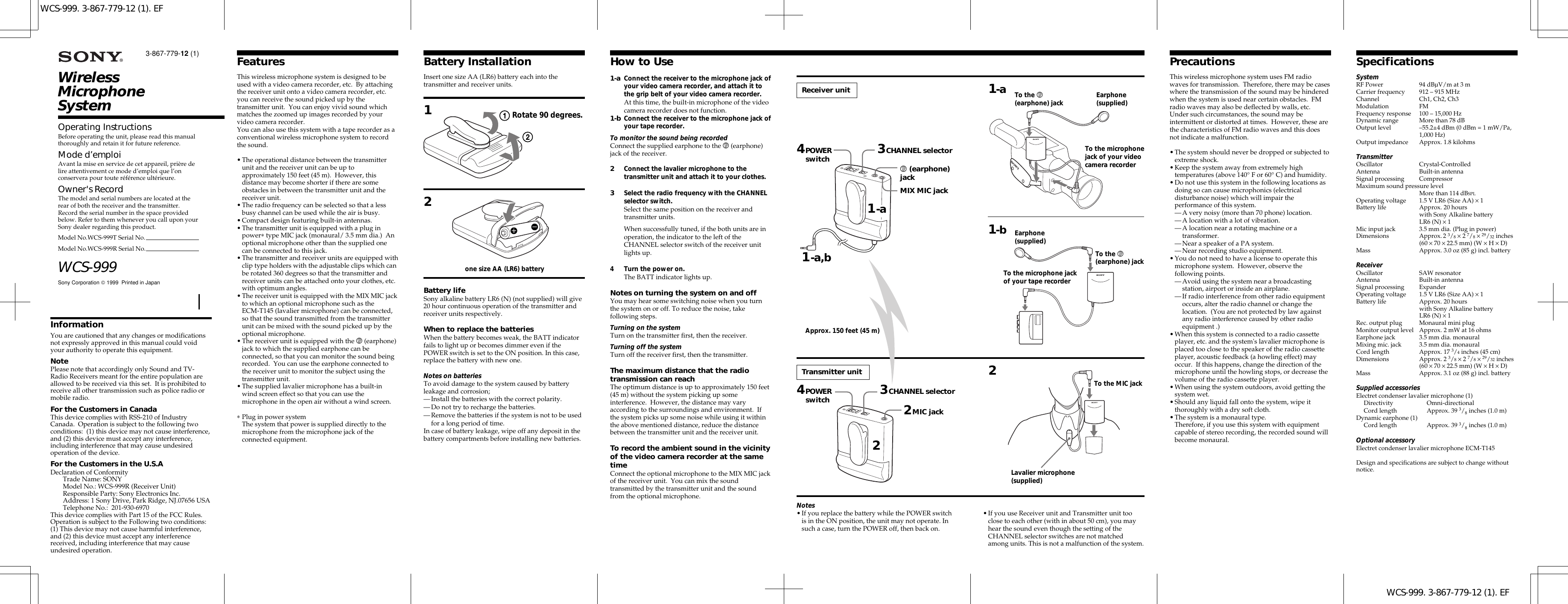
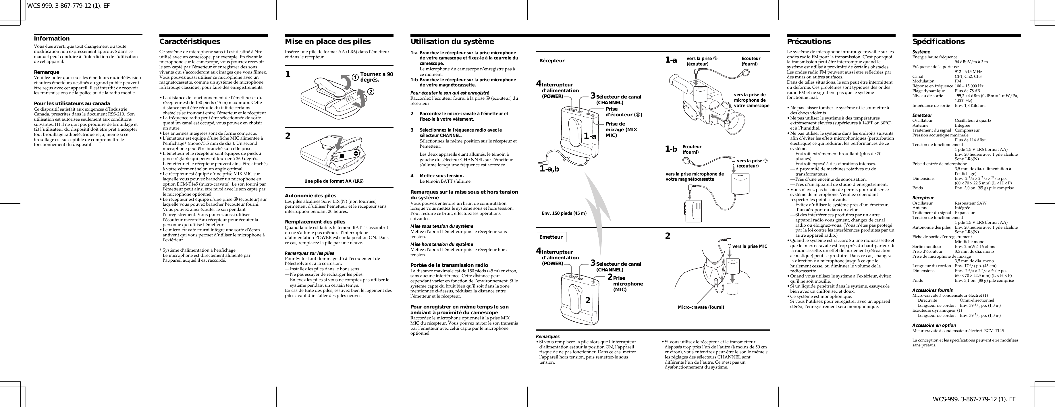
Sony Group WCS999T2 wireless microphone User Manual WCS 999

Sony Corporation wireless microphone WCS 999

Instruction Manual

WCS-999. 3-867-779-12 (1). EFWCS-999. 3-867-779-12 (1). EFWirelessMicrophoneSystemSony Corporation  1999  Printed in JapanWCS-999Operating InstructionsBefore operating the unit, please read this manualthoroughly and retain it for future reference.Mode d’emploiAvant la mise en service de cet appareil, prière delire attentivement ce mode d’emploi que l’onconservera pour toute référence ultérieure.Owner's RecordThe model and serial numbers are located at therear of both the receiver and the transmitter.Record the serial number in the space providedbelow. Refer to them whenever you call upon yourSony dealer regarding this product.Model No.WCS-999T Serial No.Model No.WCS-999R Serial No.3-867-779-12 (1)InformationYou are cautioned that any changes or modificationsnot expressly approved in this manual could voidyour authority to operate this equipment.NotePlease note that accordingly only Sound and TV-Radio Receivers meant for the entire population areallowed to be received via this set.  It is prohibited toreceive all other transmission such as police radio ormobile radio.For the Customers in CanadaThis device complies with RSS-210 of IndustryCanada.  Operation is subject to the following twoconditions:  (1) this device may not cause interference,and (2) this device must accept any interference,including interference that may cause undesiredoperation of the device.For the Customers in the U.S.ADeclaration of ConformityTrade Name: SONYModel No.: WCS-999R (Receiver Unit)Responsible Party: Sony Electronics Inc.Address: 1 Sony Drive, Park Ridge, NJ.07656 USATelephone No.:  201-930-6970This device complies with Part 15 of the FCC Rules.Operation is subject to the Following two conditions:(1) This device may not cause harmful interference,and (2) this device must accept any interferencereceived, including interference that may causeundesired operation.FeaturesThis wireless microphone system is designed to beused with a video camera recorder, etc.  By attachingthe receiver unit onto a video camera recorder, etc.you can receive the sound picked up by thetransmitter unit.  You can enjoy vivid sound whichmatches the zoomed up images recorded by yourvideo camera recorder.You can also use this system with a tape recorder as aconventional wireless microphone system to recordthe sound.•The operational distance between the transmitterunit and the receiver unit can be up toapproximately 150 feet (45 m).  However, thisdistance may become shorter if there are someobstacles in between the transmitter unit and thereceiver unit.•The radio frequency can be selected so that a lessbusy channel can be used while the air is busy.•Compact design featuring built-in antennas.•The transmitter unit is equipped with a plug inpower∗ type MIC jack (monaural/ 3.5 mm dia.)  Anoptional microphone other than the supplied onecan be connected to this jack.•The transmitter and receiver units are equipped withclip type holders with the adjustable clips which canbe rotated 360 degrees so that the transmitter andreceiver units can be attached onto your clothes, etc.with optimum angles.•The receiver unit is equipped with the MIX MIC jackto which an optional microphone such as theECM-T145 (lavalier microphone) can be connected,so that the sound transmitted from the transmitterunit can be mixed with the sound picked up by theoptional microphone.•The receiver unit is equipped with the v (earphone)jack to which the supplied earphone can beconnected, so that you can monitor the sound beingrecorded.  You can use the earphone connected tothe receiver unit to monitor the subject using thetransmitter unit.•The supplied lavalier microphone has a built-inwind screen effect so that you can use themicrophone in the open air without a wind screen.∗Plug in power systemThe system that power is supplied directly to themicrophone from the microphone jack of theconnected equipment.PrecautionsThis wireless microphone system uses FM radiowaves for transmission.  Therefore, there may be caseswhere the transmission of the sound may be hinderedwhen the system is used near certain obstacles.  FMradio waves may also be deflected by walls, etc.Under such circumstances, the sound may beintermittent or distorted at times.  However, these arethe characteristics of FM radio waves and this doesnot indicate a malfunction.•The system should never be dropped or subjected toextreme shock.•Keep the system away from extremely hightemperatures (above 140° F or 60° C) and humidity.•Do not use this system in the following locations asdoing so can cause microphonics (electricaldisturbance noise) which will impair theperformance of this system.—A very noisy (more than 70 phone) location.—A location with a lot of vibration.—A location near a rotating machine or atransformer.—Near a speaker of a PA system.—Near recording studio equipment.•You do not need to have a license to operate thismicrophone system.  However, observe thefollowing points.—Avoid using the system near a broadcastingstation, airport or inside an airplane.—If radio interference from other radio equipmentoccurs, alter the radio channel or change thelocation.  (You are not protected by law againstany radio interference caused by other radioequipment .)•When this system is connected to a radio cassetteplayer, etc. and the system's lavalier microphone isplaced too close to the speaker of the radio cassetteplayer, acoustic feedback (a howling effect) mayoccur.  If this happens, change the direction of themicrophone until the howling stops, or decrease thevolume of the radio cassette player.•When using the system outdoors, avoid getting thesystem wet.•Should any liquid fall onto the system, wipe itthoroughly with a dry soft cloth.•The system is a monaural type.Therefore, if you use this system with equipmentcapable of stereo recording, the recorded sound willbecome monaural.SpecificationsSystemRF Power 94 dBµV/m at 3 mCarrier frequency 912 – 915 MHzChannel Ch1, Ch2, Ch3Modulation FMFrequency response 100 – 15,000 HzDynamic range More than 78 dBOutput level –55.2±4 dBm (0 dBm = 1 mW/Pa,1,000 Hz)Output impedance Approx. 1.8 kilohmsTransmitterOscillator Crystal-ControlledAntenna Built-in antennaSignal processing CompressorMaximum sound pressure levelMore than 114 dBSPLOperating voltage 1.5 V LR6 (Size AA) × 1Battery life Approx. 20 hourswith Sony Alkaline batteryLR6 (N) × 1Mic input jack 3.5 mm dia. (Plug in power)Dimensions Approx. 2 3/8 × 2 7/8 × 29/32 inches(60 × 70 × 22.5 mm) (W × H × D)Mass Approx. 3.0 oz (85 g) incl. batteryReceiverOscillator SAW resonatorAntenna Built-in antennaSignal processing ExpanderOperating voltage 1.5 V LR6 (Size AA) × 1Battery life Approx. 20 hourswith Sony Alkaline batteryLR6 (N) × 1Rec. output plug Monaural mini plugMonitor output level Approx. 2 mW at 16 ohmsEarphone jack 3.5 mm dia. monauralMixing mic. jack 3.5 mm dia. monauralCord length Approx. 17 3/4 inches (45 cm)Dimensions Approx. 2 3/8 × 2 7/8 × 29/32 inches(60 × 70 × 22.5 mm) (W × H × D)Mass Approx. 3.1 oz (88 g) incl. batterySupplied accessoriesElectret condenser lavalier microphone (1)Directivity Omni-directionalCord length Approx. 39 3/8 inches (1.0 m)Dynamic earphone (1)Cord length Approx. 39 3/8 inches (1.0 m)Optional accessoryElectret condenser lavalier microphone ECM-T145Design and specifications are subject to change withoutnotice.1-a1-a Connect the receiver to the microphone jack ofyour video camera recorder, and attach it tothe grip belt of your video camera recorder.At this time, the built-in microphone of the videocamera recorder does not function.1-b Connect the receiver to the microphone jack ofyour tape recorder.To monitor the sound being recordedConnect the supplied earphone to the v (earphone)jack of the receiver.2Connect the lavalier microphone to thetransmitter unit and attach it to your clothes.3Select the radio frequency with the CHANNELselector switch.Select the same position on the receiver andtransmitter units.When successfully tuned, if the both units are inoperation, the indicator to the left of theCHANNEL selector switch of the receiver unitlights up.4 Turn the power on.The BATT indicator lights up.Notes on turning the system on and offYou may hear some switching noise when you turnthe system on or off. To reduce the noise, takefollowing steps.Turning on the systemTurn on the transmitter first, then the receiver.Turning off the systemTurn off the receiver first, then the transmitter.The maximum distance that the radiotransmission can reachThe optimum distance is up to approximately 150 feet(45 m) without the system picking up someinterference.  However, the distance may varyaccording to the surroundings and environment.  Ifthe system picks up some noise while using it withinthe above mentioned distance, reduce the distancebetween the transmitter unit and the receiver unit.To record the ambient sound in the vicinityof the video camera recorder at the sametimeConnect the optional microphone to the MIX MIC jackof the receiver unit.  You can mix the soundtransmitted by the transmitter unit and the soundfrom the optional microphone.How to UseBattery InstallationInsert one size AA (LR6) battery each into thetransmitter and receiver units.12Battery lifeSony alkaline battery LR6 (N) (not supplied) will give20 hour continuous operation of the transmitter andreceiver units respectively.When to replace the batteriesWhen the battery becomes weak, the BATT indicatorfails to light up or becomes dimmer even if thePOWER switch is set to the ON position. In this case,replace the battery with new one.Notes on batteriesTo avoid damage to the system caused by batteryleakage and corrosion;—Install the batteries with the correct polarity.—Do not try to recharge the batteries.—Remove the batteries if the system is not to be usedfor a long period of time.In case of battery leakage, wipe off any deposit in thebattery compartments before installing new batteries.one size AA (LR6) batteryReceiver unit4POWERswitch1-a,b To the v(earphone) jackTo the microphone jackof your tape recorderTransmitter unit2MIC jackLavalier microphone(supplied)To the MIC jack3CHANNEL selector1-a2Earphone(supplied)1-bTo the microphonejack of your videocamera recorderEarphone(supplied)4POWERswitch 3CHANNEL selectorTo the v(earphone) jackv (earphone)jackMIX MIC jackApprox. 150 feet (45 m)Rotate 90 degrees.2Notes•If you replace the battery while the POWER switchis in the ON position, the unit may not operate. Insuch a case, turn the POWER off, then back on.•If you use Receiver unit and Transmitter unit tooclose to each other (with in about 50 cm), you mayhear the sound even though the setting of theCHANNEL selector switches are not matchedamong units. This is not a malfunction of the system.
WCS-999. 3-867-779-12 (1). EFWCS-999. 3-867-779-12 (1). EFInformationVous êtes averti que tout changement ou toutemodification non expressément approuvé dans cemanuel peut conduire à l’interdiction de l’utilisationde cet appareil.RemarqueVeuillez noter que seuls les émetteurs radio-télévisionet autres émetteurs destinés au grand public peuventêtre reçus avec cet appareil. Il est interdit de recevoirles transmissions de la police ou de la radio mobile.Pour les utilisateurs au canadaCe dispositif satisfait aux exigences d’IndustrieCanada, prescrites dans le document RSS-210.  Sonutilisation est autorisée seulement aux conditionssuivantes: (1) il ne doit pas produire de brouillage et(2) l’utilisateur du dispositif doit être prêt à acceptertout brouillage radioeléctrique reçu, même si cebrouillage est susceptible de compromettre lefonctionnement du dispositif.CaractéristiquesCe système de microphone sans fil est destiné à êtreutilisé avec un camescope, par exemple. En fixant lemicrophone sur le camescope, vous pourrez recevoirle son capté par l’émetteur et enregistrer des sonsvivants qui s’accorderont aux images que vous filmez.Vous pouvez aussi utiliser ce microphone avec unmagnétocassette, comme un système de microphoneinfrarouge classique, pour faire des enregistrements.•La distance de fonctionnement de l’émetteur et durécepteur est de 150 pieds (45 m) maximum. Cettedistance peut être réduite du fait de certainsobstacles se trouvant entre l’émetteur et le récepteur.•La fréquence radio peut être sélectionnée de sorteque si un canal est occupé, vous pouvez en choisirun autre.•Les antennes intégrées sont de forme compacte.•L’émetteur est équipé d’une fiche MIC alimentée àl’enfichage* (mono/3,5 mm de dia.). Un secondmicrophone peut être branché sur cette prise.•L’émetteur et le récepteur sont équipés de pieds àpince réglable qui peuvent tourner à 360 degrés.L’émetteur et le récepteur peuvent ainsi être attachésà votre vêtement selon un angle optimal.•Le récepteur est équipé d’une prise MIX MIC surlaquelle vous pouvez brancher un microphone enoption ECM-T145 (micro-cravate). Le son fourni parl’émetteur peut ainsi être mixé avec le son capté parle microphone optionnel.•Le récepteur est équipé d’une prise v (écouteur) surlaquelle vous pouvez brancher l’écouteur fourni.Vous pouvez ainsi écouter le son pendantl’enregistrement. Vous pouvez aussi utiliserl’écouteur raccordé au récepteur pour écouter lapersonne qui utilise l’émetteur.•Le micro-cravate fourni intègre une sorte d’écranantivent qui vous permet d’utiliser le microphone àl’extérieur.*Système d’alimentation à l’enfichageLe microphone est directement alimenté parl’appareil auquel il est raccordé.PrécautionsLe système de microphone infrarouge travaille sur lesondes radio FM pour la transmission. C’est pourquoila transmission peut être interrompue quand lesystème est utilisé à proximité de certains obstacles.Les ondes radio FM peuvent aussi être réfléchies pardes murs ou autres surfaces.Dans de telles situations, le son peut être intermittentou déformé. Ces problèmes sont typiques des ondesradio FM et ne signifient pas que le systèmefonctionne mal.•Ne pas laisser tomber le système ni le soumettre àdes chocs violents.•Ne pas utiliser le système à des températuresextrêmement élevées (supérieures à 140°F ou 60°C)et à l’humidité.•Ne pas utiliser le système dans les endroits suivantsafin d’éviter les effets microphoniques (perturbationélectrique) ce qui réduirait les performances de cesystème.—Endroit extrêmement brouillant (plus de 70phones).—Endroit exposé à des vibrations intenses.—A proximité de machines rotatives ou detransformateurs.—Près d’une enceinte de sonorisation.—Près d’un appareil de studio d’enregistrement.•Vous n’avez pas besoin de permis pour utiliser cesystème de microphone. Veuillez cependantrespecter les points suivants.—Evitez d’utiliser le système près d’un émetteur,d’un aéroport ou dans un avion.—Si des interférences produites par un autreappareil radio vous gênent, changez de canalradio ou éloignez-vous. (Vous n’êtes pas protégépar la loi contre les interférences produites par unautre appareil radio.)•Quand le système est raccordé à une radiocassette etque le micro-cravate est trop près du haut-parleur dela radiocassette, un effet de hurlement (rétroactionacoustique) peut se produire. Dans ce cas, changezla direction du microphone jusqu’à ce que lehurlement cesse, ou diminuer le volume de laradiocassette.•Quand vous utilisez le système à l’extérieur, évitezqu’il ne soit mouillé.•Si un liquide pénétrait dans le système, essuyez-lebien avec un chiffon sec et doux.•Ce système est monophonique.Si vous l’utilisez pour enregistrer avec un appareilstéréo, l’enregistrement sera monophonique.SpécificationsSystèmeEnergie haute fréquence94 dBµV/m à 3 mFréquence de la porteuse912 – 915 MHzCanal Ch1, Ch2, Ch3Modulation FMRéponse en fréquence 100 – 15.000 HzPlage dynamique Plus de 78 dBNiveau de sortie –55,2 ±4 dBm (0 dBm = 1 mW/Pa,1.000 Hz)Impédance de sortie Env. 1,8 KilohmsEmetteurOscillateur Oscillateur à quartzAntenne IntégréeTraitement du signal CompresseurPression acoustique maximalePlus de 114 dBSPLTension de fonctionnement1 pile 1,5 V LR6 (format AA)Env. 20 heures avec 1 pile alcalineSony LR6(N)Prise d’entrée de microphone3,5 mm de dia. (alimentation àl’enfichage)Dimensions Env.  2 3/8 × 2 7/8 × 29/32 po.(60 × 70 × 22,5 mm) (L × H × P)Poids Env. 3,0 on. (85 g) pile compriseRécepteurOscillateur Résonateur SAWAntenne IntégréeTraitement du signal ExpanseurTension de fonctionnement1 pile 1,5 V LR6 (format AA)Autonomie des piles Env. 20 heures avec 1 pile alcalineSony LR6(N)Fiche de sortie d’enregistrementMinifiche monoSortie moniteur Env. 2 mW à 16 ohmsPrise d’écouteur 3,5 mm de dia. monoPrise de microphone de mixage3,5 mm de dia. monoLongueur du cordon Env. 17 3/4 po. (45 cm)Dimensions Env.  2 3/8 × 2 7/8 × 29/32 po.(60 × 70 × 22,5 mm) (L × H × P)Poids Env. 3,1 on. (88 g) pile compriseAccessoires fournisMicro-cravate à condensateur électret (1)Directivité Omni-directionnelLongueur de cordon Env. 39 3/8 po. (1,0 m)Ecouteurs dynamiques  (1)Longueur de cordon Env. 39 3/8 po. (1,0 m)Accessoire en optionMicor-cravate à condensateur électret  ECM-T145La conception et les spécifications peuvent être modifiéessans préavis.1-aUtilisation du systèmeMise en place des pilesInsérez une pile de format AA (LR6) dans l’émetteuret dans le récepteur.12Autonomie des pilesLes piles alcalines Sony LR6(N) (non fournies)permettent d’utiliser l’émetteur et le récepteur sansinterruption pendant 20 heures.Remplacement des pilesQuand la pile est faible, le témoin BATT s’assombritou ne s’allume pas même si l’interrupteurd’alimentation POWER est sur la position ON. Dansce cas, remplacez la pile par une neuve.Remarques sur les pilesPour éviter tout dommage dû à l’écoulement del’électrolyte et à la corrosion;—Installez les piles dans le bons sens.—Ne pas essayer de recharger les piles.—Enlevez les piles si vous ne comptez pas utiliser lesystème pendant un certain temps.En cas de fuite des piles, essuyez bien le logement despiles avant d’installer des piles neuves.Récepteur1-a,b vers la prise v(écouteur)2EmetteurMicro-cravate (fourni)3Sélecteur de canal(CHANNEL)1-aEcouteur(fourni)1-bvers la prise demicrophone devotre camescopeEcouteur(fourni)vers la prise v(écouteur)Prise demixage (MIXMIC)Env. 150 pieds (45 m)1-a Branchez le récepteur sur la prise microphonede votre camescope et fixez-le à la courroie ducamescope.Le microphone du camescope n’enregistre pas àce moment.1-b Branchez le récepteur sur la prise microphonede votre magnétocassette.Pour écouter le son qui est enregistréRaccordez l’écouteur fourni à la prise v (écouteur) durécepteur.2Raccordez le micro-cravate à l’émetteur etfixez-le à votre vêtement.3Sélectionnez la fréquence radio avec lesélecteur CHANNEL.Sélectionnez la même position sur le récepteur etl’émetteur.Les deux appareils étant allumés, le témoin àgauche du sélecteur CHANNEL sur l’émetteurs’allume lorsqu’une fréquence est accordée.4Mettez sous tension.Le témoin BATT s’allume.Remarques sur la mise sous et hors tensiondu systèmeVous pouvez entendre un bruit de commutationlorsque vous mettez le système sous et hors tension.Pour réduire ce bruit, effectuez les opérationssuivantes.Mise sous tension du systèmeMettez d’abord l’émetteur puis le récepteur soustension.Mise hors tension du systèmeMettez d’abord l’émetteur puis le récepteur horstension.Portée de la transmission radioLa distance maximale est de 150 pieds (45 m) environ,sans aucune interférence. Cette distance peutcependant varier en fonction de l’environnement. Si lesystème capte du bruit bien qu’il soit dans la zonementionnée ci-dessus, réduisez la distance entrel’émetteur et le récepteur.Pour enregistrer en même temps le sonambiant à proximité du camescopeRaccordez le microphone optionnel à la prise MIXMIC du récepteur. Vous pouvez mixer le son transmispar l’émetteur avec celui capté par le microphoneoptionnel.vers la prise MICvers la prise microphone devotre magnétocassettePrised’écouteur (v)4Interrupteurd’alimentation(POWER)23Sélecteur de canal(CHANNEL)4Interrupteurd’alimentation(POWER)2Prisemicrophone(MIC)Une pile de format AA (LR6)Tournez à 90degrés.Remarques•Si vous remplacez la pile alors que l’interrupteurd’alimentation est sur la position ON, l’appareilrisque de ne pas fonctionner. Dans ce cas, mettezl’appareil hors tension, puis remettez-le soustension.•Si vous utilisez le récepteur et le transmetteurdisposés trop près l’un de l’autre (à moins de 50 cmenviron), vous entendrez peut-être le son le même siles réglages des sélecteurs CHANNEL sontdifférents l’un de l’autre. Ce n’est pas undysfonctionnement du système.

Navigation menu