Sony Group WCS999T2 wireless microphone User Manual WCS 999
Sony Corporation wireless microphone WCS 999
Instruction Manual
WCS-999. 3-867-779-12 (1). EF
WCS-999. 3-867-779-12 (1). EF
Wireless
Microphone
System
Sony Corporation 1999 Printed in Japan
WCS-999
Operating Instructions
Before operating the unit, please read this manual
thoroughly and retain it for future reference.
Mode d’emploi
Avant la mise en service de cet appareil, prière de
lire attentivement ce mode d’emploi que l’on
conservera pour toute référence ultérieure.
Owner's Record
The model and serial numbers are located at the
rear of both the receiver and the transmitter.
Record the serial number in the space provided
below. Refer to them whenever you call upon your
Sony dealer regarding this product.
Model No.WCS-999T Serial No.
Model No.WCS-999R Serial No.
3-867-779-12 (1)
Information
You are cautioned that any changes or modifications
not expressly approved in this manual could void
your authority to operate this equipment.
Note
Please note that accordingly only Sound and TV-
Radio Receivers meant for the entire population are
allowed to be received via this set. It is prohibited to
receive all other transmission such as police radio or
mobile radio.
For the Customers in Canada
This device complies with RSS-210 of Industry
Canada. Operation is subject to the following two
conditions: (1) this device may not cause interference,
and (2) this device must accept any interference,
including interference that may cause undesired
operation of the device.
For the Customers in the U.S.A
Declaration of Conformity
Trade Name: SONY
Model No.: WCS-999R (Receiver Unit)
Responsible Party: Sony Electronics Inc.
Address: 1 Sony Drive, Park Ridge, NJ.07656 USA
Telephone No.: 201-930-6970
This device complies with Part 15 of the FCC Rules.
Operation is subject to the Following two conditions:
(1) This device may not cause harmful interference,
and (2) this device must accept any interference
received, including interference that may cause
undesired operation.
Features
This wireless microphone system is designed to be
used with a video camera recorder, etc. By attaching
the receiver unit onto a video camera recorder, etc.
you can receive the sound picked up by the
transmitter unit. You can enjoy vivid sound which
matches the zoomed up images recorded by your
video camera recorder.
You can also use this system with a tape recorder as a
conventional wireless microphone system to record
the sound.
•The operational distance between the transmitter
unit and the receiver unit can be up to
approximately 150 feet (45 m). However, this
distance may become shorter if there are some
obstacles in between the transmitter unit and the
receiver unit.
•The radio frequency can be selected so that a less
busy channel can be used while the air is busy.
•Compact design featuring built-in antennas.
•The transmitter unit is equipped with a plug in
power∗ type MIC jack (monaural/ 3.5 mm dia.) An
optional microphone other than the supplied one
can be connected to this jack.
•The transmitter and receiver units are equipped with
clip type holders with the adjustable clips which can
be rotated 360 degrees so that the transmitter and
receiver units can be attached onto your clothes, etc.
with optimum angles.
•The receiver unit is equipped with the MIX MIC jack
to which an optional microphone such as the
ECM-T145 (lavalier microphone) can be connected,
so that the sound transmitted from the transmitter
unit can be mixed with the sound picked up by the
optional microphone.
•The receiver unit is equipped with the v (earphone)
jack to which the supplied earphone can be
connected, so that you can monitor the sound being
recorded. You can use the earphone connected to
the receiver unit to monitor the subject using the
transmitter unit.
•The supplied lavalier microphone has a built-in
wind screen effect so that you can use the
microphone in the open air without a wind screen.
∗Plug in power system
The system that power is supplied directly to the
microphone from the microphone jack of the
connected equipment.
Precautions
This wireless microphone system uses FM radio
waves for transmission. Therefore, there may be cases
where the transmission of the sound may be hindered
when the system is used near certain obstacles. FM
radio waves may also be deflected by walls, etc.
Under such circumstances, the sound may be
intermittent or distorted at times. However, these are
the characteristics of FM radio waves and this does
not indicate a malfunction.
•The system should never be dropped or subjected to
extreme shock.
•Keep the system away from extremely high
temperatures (above 140° F or 60° C) and humidity.
•Do not use this system in the following locations as
doing so can cause microphonics (electrical
disturbance noise) which will impair the
performance of this system.
—A very noisy (more than 70 phone) location.
—A location with a lot of vibration.
—A location near a rotating machine or a
transformer.
—Near a speaker of a PA system.
—Near recording studio equipment.
•You do not need to have a license to operate this
microphone system. However, observe the
following points.
—Avoid using the system near a broadcasting
station, airport or inside an airplane.
—If radio interference from other radio equipment
occurs, alter the radio channel or change the
location. (You are not protected by law against
any radio interference caused by other radio
equipment .)
•When this system is connected to a radio cassette
player, etc. and the system's lavalier microphone is
placed too close to the speaker of the radio cassette
player, acoustic feedback (a howling effect) may
occur. If this happens, change the direction of the
microphone until the howling stops, or decrease the
volume of the radio cassette player.
•When using the system outdoors, avoid getting the
system wet.
•Should any liquid fall onto the system, wipe it
thoroughly with a dry soft cloth.
•The system is a monaural type.
Therefore, if you use this system with equipment
capable of stereo recording, the recorded sound will
become monaural.
Specifications
System
RF Power 94 dBµV/m at 3 m
Carrier frequency 912 – 915 MHz
Channel Ch1, Ch2, Ch3
Modulation FM
Frequency response 100 – 15,000 Hz
Dynamic range More than 78 dB
Output level –55.2±4 dBm (0 dBm = 1 mW/Pa,
1,000 Hz)
Output impedance Approx. 1.8 kilohms
Transmitter
Oscillator Crystal-Controlled
Antenna Built-in antenna
Signal processing Compressor
Maximum sound pressure level
More than 114 dBSPL
Operating voltage 1.5 V LR6 (Size AA) × 1
Battery life Approx. 20 hours
with Sony Alkaline battery
LR6 (N) × 1
Mic input jack 3.5 mm dia. (Plug in power)
Dimensions Approx. 2 3/8 × 2 7/8 × 29/32 inches
(60 × 70 × 22.5 mm) (W × H × D)
Mass Approx. 3.0 oz (85 g) incl. battery
Receiver
Oscillator SAW resonator
Antenna Built-in antenna
Signal processing Expander
Operating voltage 1.5 V LR6 (Size AA) × 1
Battery life Approx. 20 hours
with Sony Alkaline battery
LR6 (N) × 1
Rec. output plug Monaural mini plug
Monitor output level Approx. 2 mW at 16 ohms
Earphone jack 3.5 mm dia. monaural
Mixing mic. jack 3.5 mm dia. monaural
Cord length Approx. 17 3/4 inches (45 cm)
Dimensions Approx. 2 3/8 × 2 7/8 × 29/32 inches
(60 × 70 × 22.5 mm) (W × H × D)
Mass Approx. 3.1 oz (88 g) incl. battery
Supplied accessories
Electret condenser lavalier microphone (1)
Directivity Omni-directional
Cord length Approx. 39 3/8 inches (1.0 m)
Dynamic earphone (1)
Cord length Approx. 39 3/8 inches (1.0 m)
Optional accessory
Electret condenser lavalier microphone ECM-T145
Design and specifications are subject to change without
notice.
1-a
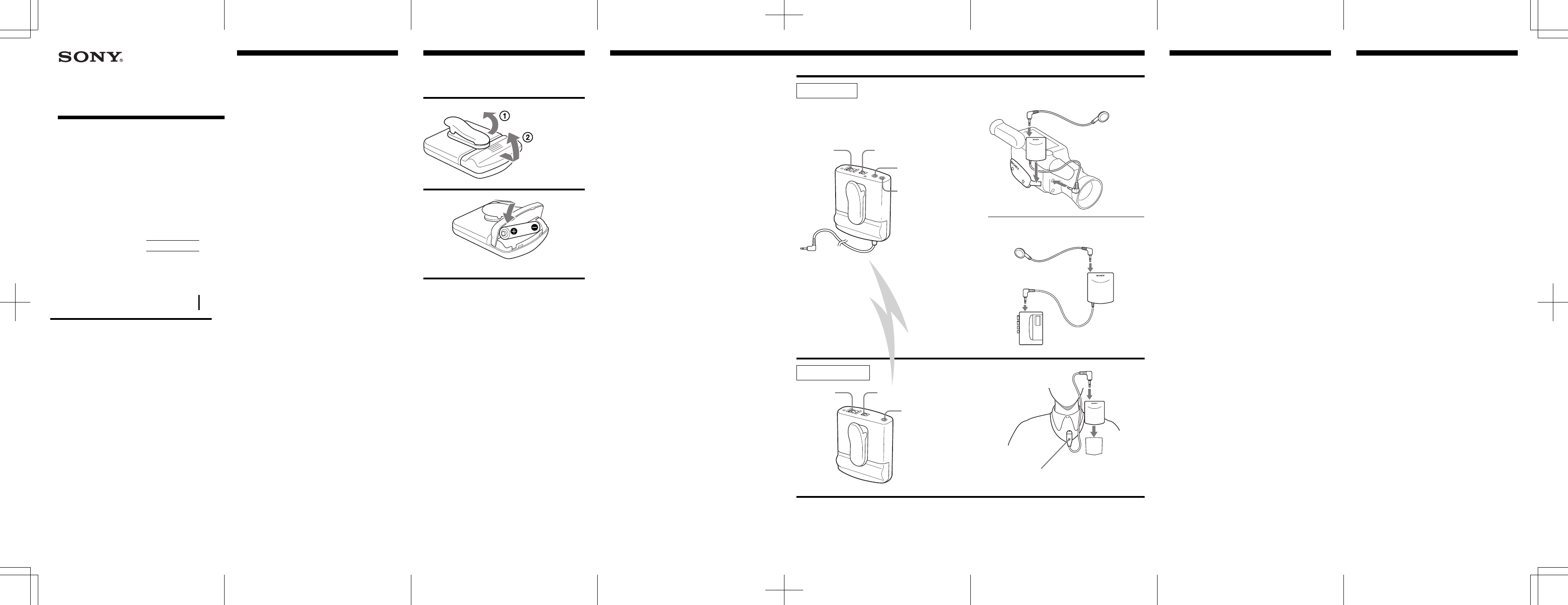
1-a Connect the receiver to the microphone jack of
your video camera recorder, and attach it to
the grip belt of your video camera recorder.
At this time, the built-in microphone of the video
camera recorder does not function.
1-b Connect the receiver to the microphone jack of
your tape recorder.
To monitor the sound being recorded
Connect the supplied earphone to the v (earphone)
jack of the receiver.
2Connect the lavalier microphone to the
transmitter unit and attach it to your clothes.
3Select the radio frequency with the CHANNEL
selector switch.
Select the same position on the receiver and
transmitter units.
When successfully tuned, if the both units are in
operation, the indicator to the left of the
CHANNEL selector switch of the receiver unit
lights up.
4 Turn the power on.
The BATT indicator lights up.
Notes on turning the system on and off
You may hear some switching noise when you turn
the system on or off. To reduce the noise, take
following steps.
Turning on the system
Turn on the transmitter first, then the receiver.
Turning off the system
Turn off the receiver first, then the transmitter.
The maximum distance that the radio
transmission can reach
The optimum distance is up to approximately 150 feet
(45 m) without the system picking up some
interference. However, the distance may vary
according to the surroundings and environment. If
the system picks up some noise while using it within
the above mentioned distance, reduce the distance
between the transmitter unit and the receiver unit.
To record the ambient sound in the vicinity
of the video camera recorder at the same
time
Connect the optional microphone to the MIX MIC jack
of the receiver unit. You can mix the sound
transmitted by the transmitter unit and the sound
from the optional microphone.
How to UseBattery Installation
Insert one size AA (LR6) battery each into the
transmitter and receiver units.
1
2
Battery life
Sony alkaline battery LR6 (N) (not supplied) will give
20 hour continuous operation of the transmitter and
receiver units respectively.
When to replace the batteries
When the battery becomes weak, the BATT indicator
fails to light up or becomes dimmer even if the
POWER switch is set to the ON position. In this case,
replace the battery with new one.
Notes on batteries
To avoid damage to the system caused by battery
leakage and corrosion;
—Install the batteries with the correct polarity.
—Do not try to recharge the batteries.
—Remove the batteries if the system is not to be used
for a long period of time.
In case of battery leakage, wipe off any deposit in the
battery compartments before installing new batteries.
one size AA (LR6) battery
Receiver unit
4POWER
switch
1-a,b To the v
(earphone) jack
To the microphone jack
of your tape recorder
Transmitter unit
2MIC jack
Lavalier microphone
(supplied)
To the MIC jack
3CHANNEL selector
1-a
2
Earphone
(supplied)
1-b
To the microphone
jack of your video
camera recorder
Earphone
(supplied)
4POWER
switch 3CHANNEL selector
To the v
(earphone) jack
v (earphone)
jack
MIX MIC jack
Approx. 150 feet (45 m)
Rotate 90 degrees.
2
Notes
•If you replace the battery while the POWER switch
is in the ON position, the unit may not operate. In
such a case, turn the POWER off, then back on.
•If you use Receiver unit and Transmitter unit too
close to each other (with in about 50 cm), you may
hear the sound even though the setting of the
CHANNEL selector switches are not matched
among units. This is not a malfunction of the system.
WCS-999. 3-867-779-12 (1). EF
WCS-999. 3-867-779-12 (1). EF
Information
Vous êtes averti que tout changement ou toute
modification non expressément approuvé dans ce
manuel peut conduire à l’interdiction de l’utilisation
de cet appareil.
Remarque
Veuillez noter que seuls les émetteurs radio-télévision
et autres émetteurs destinés au grand public peuvent
être reçus avec cet appareil. Il est interdit de recevoir
les transmissions de la police ou de la radio mobile.
Pour les utilisateurs au canada
Ce dispositif satisfait aux exigences d’Industrie
Canada, prescrites dans le document RSS-210. Son
utilisation est autorisée seulement aux conditions
suivantes: (1) il ne doit pas produire de brouillage et
(2) l’utilisateur du dispositif doit être prêt à accepter
tout brouillage radioeléctrique reçu, même si ce
brouillage est susceptible de compromettre le
fonctionnement du dispositif.
Caractéristiques
Ce système de microphone sans fil est destiné à être
utilisé avec un camescope, par exemple. En fixant le
microphone sur le camescope, vous pourrez recevoir
le son capté par l’émetteur et enregistrer des sons
vivants qui s’accorderont aux images que vous filmez.
Vous pouvez aussi utiliser ce microphone avec un
magnétocassette, comme un système de microphone
infrarouge classique, pour faire des enregistrements.
•La distance de fonctionnement de l’émetteur et du
récepteur est de 150 pieds (45 m) maximum. Cette
distance peut être réduite du fait de certains
obstacles se trouvant entre l’émetteur et le récepteur.
•La fréquence radio peut être sélectionnée de sorte
que si un canal est occupé, vous pouvez en choisir
un autre.
•Les antennes intégrées sont de forme compacte.
•L’émetteur est équipé d’une fiche MIC alimentée à
l’enfichage* (mono/3,5 mm de dia.). Un second
microphone peut être branché sur cette prise.
•L’émetteur et le récepteur sont équipés de pieds à
pince réglable qui peuvent tourner à 360 degrés.
L’émetteur et le récepteur peuvent ainsi être attachés
à votre vêtement selon un angle optimal.
•Le récepteur est équipé d’une prise MIX MIC sur
laquelle vous pouvez brancher un microphone en
option ECM-T145 (micro-cravate). Le son fourni par
l’émetteur peut ainsi être mixé avec le son capté par
le microphone optionnel.
•Le récepteur est équipé d’une prise v (écouteur) sur
laquelle vous pouvez brancher l’écouteur fourni.
Vous pouvez ainsi écouter le son pendant
l’enregistrement. Vous pouvez aussi utiliser
l’écouteur raccordé au récepteur pour écouter la
personne qui utilise l’émetteur.
•Le micro-cravate fourni intègre une sorte d’écran
antivent qui vous permet d’utiliser le microphone à
l’extérieur.
*Système d’alimentation à l’enfichage
Le microphone est directement alimenté par
l’appareil auquel il est raccordé.
Précautions
Le système de microphone infrarouge travaille sur les
ondes radio FM pour la transmission. C’est pourquoi
la transmission peut être interrompue quand le
système est utilisé à proximité de certains obstacles.
Les ondes radio FM peuvent aussi être réfléchies par
des murs ou autres surfaces.
Dans de telles situations, le son peut être intermittent
ou déformé. Ces problèmes sont typiques des ondes
radio FM et ne signifient pas que le système
fonctionne mal.
•Ne pas laisser tomber le système ni le soumettre à
des chocs violents.
•Ne pas utiliser le système à des températures
extrêmement élevées (supérieures à 140°F ou 60°C)
et à l’humidité.
•Ne pas utiliser le système dans les endroits suivants
afin d’éviter les effets microphoniques (perturbation
électrique) ce qui réduirait les performances de ce
système.
—Endroit extrêmement brouillant (plus de 70
phones).
—Endroit exposé à des vibrations intenses.
—A proximité de machines rotatives ou de
transformateurs.
—Près d’une enceinte de sonorisation.
—Près d’un appareil de studio d’enregistrement.
•Vous n’avez pas besoin de permis pour utiliser ce
système de microphone. Veuillez cependant
respecter les points suivants.
—Evitez d’utiliser le système près d’un émetteur,
d’un aéroport ou dans un avion.
—Si des interférences produites par un autre
appareil radio vous gênent, changez de canal
radio ou éloignez-vous. (Vous n’êtes pas protégé
par la loi contre les interférences produites par un
autre appareil radio.)
•Quand le système est raccordé à une radiocassette et
que le micro-cravate est trop près du haut-parleur de
la radiocassette, un effet de hurlement (rétroaction
acoustique) peut se produire. Dans ce cas, changez
la direction du microphone jusqu’à ce que le
hurlement cesse, ou diminuer le volume de la
radiocassette.
•Quand vous utilisez le système à l’extérieur, évitez
qu’il ne soit mouillé.
•Si un liquide pénétrait dans le système, essuyez-le
bien avec un chiffon sec et doux.
•Ce système est monophonique.
Si vous l’utilisez pour enregistrer avec un appareil
stéréo, l’enregistrement sera monophonique.
Spécifications
Système
Energie haute fréquence
94 dBµV/m à 3 m
Fréquence de la porteuse
912 – 915 MHz
Canal Ch1, Ch2, Ch3
Modulation FM
Réponse en fréquence 100 – 15.000 Hz
Plage dynamique Plus de 78 dB
Niveau de sortie –55,2 ±4 dBm (0 dBm = 1 mW/Pa,
1.000 Hz)
Impédance de sortie Env. 1,8 Kilohms
Emetteur
Oscillateur Oscillateur à quartz
Antenne Intégrée
Traitement du signal Compresseur
Pression acoustique maximale
Plus de 114 dBSPL
Tension de fonctionnement
1 pile 1,5 V LR6 (format AA)
Env. 20 heures avec 1 pile alcaline
Sony LR6(N)
Prise d’entrée de microphone
3,5 mm de dia. (alimentation à
l’enfichage)
Dimensions Env. 2 3/8 × 2 7/8 × 29/32 po.
(60 × 70 × 22,5 mm) (L × H × P)
Poids Env. 3,0 on. (85 g) pile comprise
Récepteur
Oscillateur Résonateur SAW
Antenne Intégrée
Traitement du signal Expanseur
Tension de fonctionnement
1 pile 1,5 V LR6 (format AA)
Autonomie des piles Env. 20 heures avec 1 pile alcaline
Sony LR6(N)
Fiche de sortie d’enregistrement
Minifiche mono
Sortie moniteur Env. 2 mW à 16 ohms
Prise d’écouteur 3,5 mm de dia. mono
Prise de microphone de mixage
3,5 mm de dia. mono
Longueur du cordon Env. 17 3/4 po. (45 cm)
Dimensions Env. 2 3/8 × 2 7/8 × 29/32 po.
(60 × 70 × 22,5 mm) (L × H × P)
Poids Env. 3,1 on. (88 g) pile comprise
Accessoires fournis
Micro-cravate à condensateur électret (1)
Directivité Omni-directionnel
Longueur de cordon Env. 39 3/8 po. (1,0 m)
Ecouteurs dynamiques (1)
Longueur de cordon Env. 39 3/8 po. (1,0 m)
Accessoire en option
Micor-cravate à condensateur électret ECM-T145
La conception et les spécifications peuvent être modifiées
sans préavis.
1-a
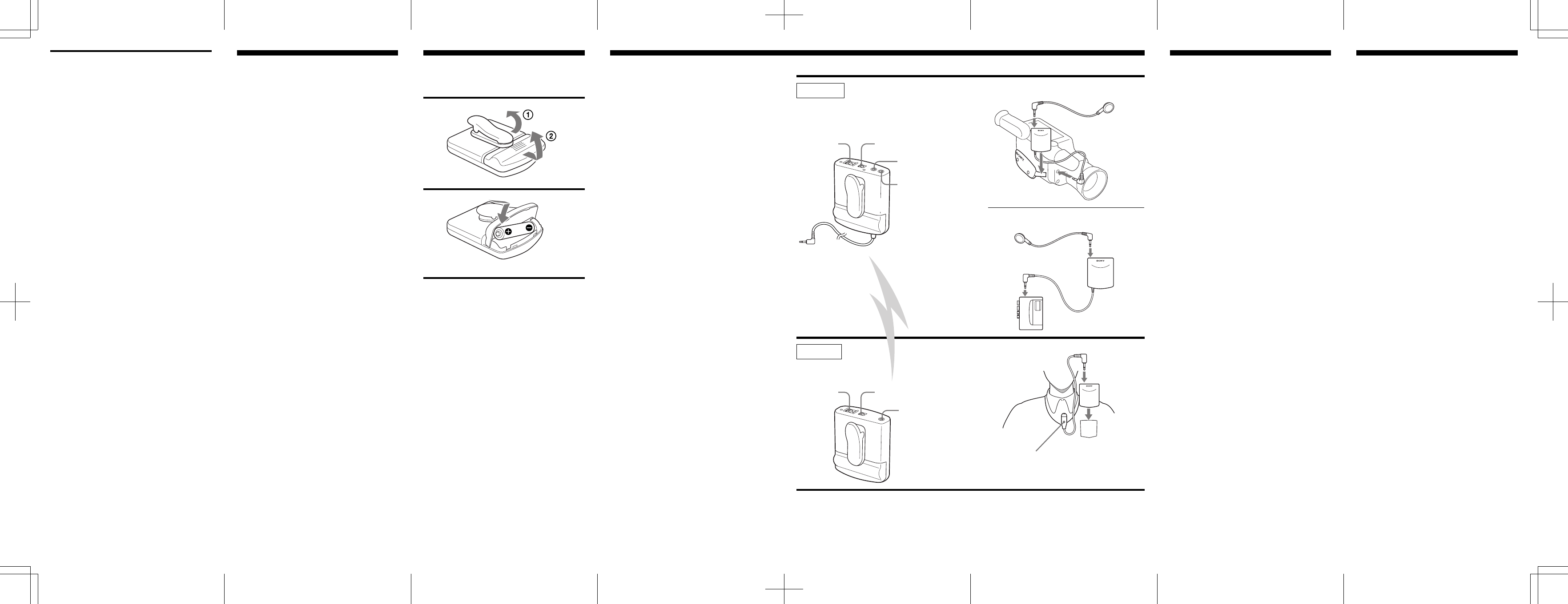
Utilisation du systèmeMise en place des piles
Insérez une pile de format AA (LR6) dans l’émetteur
et dans le récepteur.
1
2
Autonomie des piles
Les piles alcalines Sony LR6(N) (non fournies)
permettent d’utiliser l’émetteur et le récepteur sans
interruption pendant 20 heures.
Remplacement des piles
Quand la pile est faible, le témoin BATT s’assombrit
ou ne s’allume pas même si l’interrupteur
d’alimentation POWER est sur la position ON. Dans
ce cas, remplacez la pile par une neuve.
Remarques sur les piles
Pour éviter tout dommage dû à l’écoulement de
l’électrolyte et à la corrosion;
—Installez les piles dans le bons sens.
—Ne pas essayer de recharger les piles.
—Enlevez les piles si vous ne comptez pas utiliser le
système pendant un certain temps.
En cas de fuite des piles, essuyez bien le logement des
piles avant d’installer des piles neuves.
Récepteur
1-a,b vers la prise v
(écouteur)
2
Emetteur
Micro-cravate (fourni)
3Sélecteur de canal
(CHANNEL)
1-a
Ecouteur
(fourni)
1-b
vers la prise de
microphone de
votre camescope
Ecouteur
(fourni)
vers la prise v
(écouteur)
Prise de
mixage (MIX
MIC)
Env. 150 pieds (45 m)
1-a Branchez le récepteur sur la prise microphone
de votre camescope et fixez-le à la courroie du
camescope.
Le microphone du camescope n’enregistre pas à
ce moment.
1-b Branchez le récepteur sur la prise microphone
de votre magnétocassette.
Pour écouter le son qui est enregistré
Raccordez l’écouteur fourni à la prise v (écouteur) du
récepteur.
2Raccordez le micro-cravate à l’émetteur et
fixez-le à votre vêtement.
3Sélectionnez la fréquence radio avec le
sélecteur CHANNEL.
Sélectionnez la même position sur le récepteur et
l’émetteur.
Les deux appareils étant allumés, le témoin à
gauche du sélecteur CHANNEL sur l’émetteur
s’allume lorsqu’une fréquence est accordée.
4Mettez sous tension.
Le témoin BATT s’allume.
Remarques sur la mise sous et hors tension
du système
Vous pouvez entendre un bruit de commutation
lorsque vous mettez le système sous et hors tension.
Pour réduire ce bruit, effectuez les opérations
suivantes.
Mise sous tension du système
Mettez d’abord l’émetteur puis le récepteur sous
tension.
Mise hors tension du système
Mettez d’abord l’émetteur puis le récepteur hors
tension.
Portée de la transmission radio
La distance maximale est de 150 pieds (45 m) environ,
sans aucune interférence. Cette distance peut
cependant varier en fonction de l’environnement. Si le
système capte du bruit bien qu’il soit dans la zone
mentionnée ci-dessus, réduisez la distance entre
l’émetteur et le récepteur.
Pour enregistrer en même temps le son
ambiant à proximité du camescope
Raccordez le microphone optionnel à la prise MIX
MIC du récepteur. Vous pouvez mixer le son transmis
par l’émetteur avec celui capté par le microphone
optionnel.
vers la prise MIC
vers la prise microphone de
votre magnétocassette
Prise
d’écouteur (v)
4Interrupteur
d’alimentation
(POWER)
2
3Sélecteur de canal
(CHANNEL)
4Interrupteur
d’alimentation
(POWER)
2Prise
microphone
(MIC)
Une pile de format AA (LR6)
Tournez à 90
degrés.
Remarques
•Si vous remplacez la pile alors que l’interrupteur
d’alimentation est sur la position ON, l’appareil
risque de ne pas fonctionner. Dans ce cas, mettez
l’appareil hors tension, puis remettez-le sous
tension.
•Si vous utilisez le récepteur et le transmetteur
disposés trop près l’un de l’autre (à moins de 50 cm
environ), vous entendrez peut-être le son le même si
les réglages des sélecteurs CHANNEL sont
différents l’un de l’autre. Ce n’est pas un
dysfonctionnement du système.