Sony 6220512 Mobile Base Unit User Manual GT47 Integrators Manual
Sony Mobile Communications Inc Mobile Base Unit GT47 Integrators Manual
Sony >
Contents
- 1. Technical Manual
- 2. Integrators Manual
Integrators Manual

Product Photo/Illustration
GT47/GT48
Integrators Manual

The product described in this manual conforms to the Radio and Telecommunication
Terminal Equipment (R&TTE) directive 99/5/EC with requirements covering EMC
directive 89/336/EEC and Low Voltage directive 73/23/EEC. The product fulfils the
requirements according to 3GPP TS 51.010-1, EN 301 489-7 and EN60950.
SAR statement: This product is intended to be used with the antenna or other radiating
element at least 20cm away from any part of the human body.
The information contained in this document is the proprietary information of
Sony Ericsson Mobile Communications International. The contents are confidential
and any disclosure to persons other than the officers, employees, agents or subcontractors
of the owner or licensee of this document, without the prior written consent of
Sony Ericsson Mobile Communications International, is strictly prohibited. Further,
no portion of this publication may be reproduced, stored in a retrieval system, or
transmitted in any form or by any means, electronic or mechanical, including
photocopying and recording, without the prior written consent of Sony Ericsson Mobile
Communications International, the copyright holder.
First edition (August 2003)
Sony Ericsson Mobile Communications International publishes this manual without
making any warranty as to the content contained herein. Further Sony Ericsson Mobile
Communications International reserves the right to make modifications, additions and
deletions to this manual due to typographical errors, inaccurate information, or
improvements to programs and/or equipment at any time and without notice. Such
changes will, nevertheless be incorporated into new editions of this manual.
All rights reserved.
© Sony Ericsson Mobile Communications International, 2003
Publication number: LZT 123 7605 P1C
Printed in UK

3
LZ T 123 7605 P1C
Contents
Overview ...................................................................................................................5
1. Introduction .............................................................................................................. 6
Target Users................................................................................................................ 6
Prerequisites................................................................................................................ 6
Manual Structure......................................................................................................... 6
2. GT47/GT48 Control Terminals................................................................................ 7
Description.................................................................................................................. 7
Highlights .................................................................................................................. 7
Control Terminals in a Communication System........................................................... 8
Main Features and Services ....................................................................................... 10
Service and Support ................................................................................................... 15
Precautions................................................................................................................ 15
3. Abbreviations and Definitions............................................................................... 16
Integrating the Control Terminal ...........................................................................18
4. Mechanical Description.......................................................................................... 19
Overview................................................................................................................... 19
Physical Dimensions.................................................................................................. 21
5. Electrical Description ............................................................................................. 22
Power Supply and Extended I/O Connector ............................................................... 22
RS232 Serial and Extended I/O Interface ................................................................... 25
Audio Connector ....................................................................................................... 31
Antenna Connector.................................................................................................... 33
SIM Card Reader ....................................................................................................... 34
Real Time Clock........................................................................................................ 35
Software Updates....................................................................................................... 35
6. Embedded Applications ......................................................................................... 36
Features..................................................................................................................... 36
Implementation......................................................................................................... 36
7. TCP/IP Stack........................................................................................................... 38
Implementation......................................................................................................... 38
8. Operation................................................................................................................. 39
Switching On the Control Terminal .......................................................................... 39
Switching Off the Control Terminal .......................................................................... 39

4
LZ T 123 7605 P1C
Resetting the Control Terminal................................................................................. 39
Operating States/LED................................................................................................ 39
Power Save ................................................................................................................ 40
Controller Mode ........................................................................................................ 40
9. Safety and Product Care ......................................................................................... 41
Safety Instructions ..................................................................................................... 41
General Precautions................................................................................................... 41
SIM Card Precautions ................................................................................................ 42
Antenna Precautions.................................................................................................. 42
10. Installation of the Control Terminal...................................................................... 44
Where to Install the Control Terminal ...................................................................... 44
How to Install the Control Terminal ......................................................................... 45
Antenna .................................................................................................................... 46
Accessories ................................................................................................................ 47
11. Technical Data ........................................................................................................ 49

Product Photo/Illustration
Overview

6
LZ T 123 7605 P1C
1. Introduction
1.1 Target Users
GT47 and GT48 Control Terminals are designed to be integrated into
machine-machine or man-to-machine communications applications. They
are intended to be used by manufacturers, system integrators, applications
developers and developers of wireless communications equipment.
1.2 Prerequisites
It is assumed that the person integrating the GT47/GT48 into an
application has a basic understanding of the following:
• GSM networking;
• Wireless communication and antennas (aerials);
• AT commands;
• ITU-T standard V.24/V.28;
• Micro controllers and programming;
• Electronic hardware design.
1.3 Manual Structure
The manual is composed of two parts
Part 1- Overview
This section provides a broad overview of the GT47/GT48 and includes a
list of abbreviations used in the manual.
Part 2 - Integrating the Control Terminal
This section describes each of the signals available on the GT47/GT48
Control Terminal, along with mechanical information. The section also
provides you with design guidelines and explains what is needed to
commercialise an application from a regulatory point of view.

2. GT47/GT48 CONTROL TERMINALS
7
LZ T 123 7605 P1C
2. GT47/GT48 Control Terminals
2.1 Description
Two Control Terminals make up the family; GT47 and GT48, for use in
the E-GSM900/GSM1800 and GSM850/GSM1900 bands respectively.
The Control Terminal has a radio device embedded in it. The GT47
incorporates the GR47 radio device; the GT48 incorporates the GR48
radio device.
Note! This manual refers to the GT47 and GT48 as Control Terminals. If there
is a difference in the functionality of the Control Terminals the GT47 and
GT48 information will be listed separately.
The Control Terminal is a powerful and flexible device that can be used in
a wide range of telemetry and telematics applications that rely on the
remote exchange of data, voice, SMS or faxes via the GSM cellular network.
Small and lightweight, the Control Terminal has standard connectors and
an integral SIM card reader making it easy and quick to integrate. As well
as providing a standard RS232 serial communication interface the Control
Terminal also has an audio interface allowing an analogue handset to be
connected. When the Control Terminal is integrated into an external
application, a wireless communications system is created.
A typical end-to-end system consists of a micro controller in an external
application communicating, via the Control Terminal, with a remote
terminal or host using the GSM network. The micro controller uses a set of
AT commands to control the Control Terminal, and to set up the end-to-
end communications link, via its 9-way RS232 serial interface.
These Control Terminals are intended to be used by manufacturers, system
integrators, application developers and developers of a wide range of
equipment and business solutions, typically in the following fields:
• Security and alarms
• Vending
• Monitoring and control
• Utilities
• Fleet Management
2.2 Highlights
• Intelligent, versatile GSM/GPRS Control Terminal
• Dual band, EGSM 900/GSM1800 (GT47);
GSM 850/GSM1900 (GT48)
• Customised applications can be embedded and run independently
• Self contained terminal with standard connectors

2. GT47/GT48 CONTROL TERMINALS
8
LZ T 123 7605 P1C
• 2 x RS232 interfaces with a useful range of configurable IOs
• TCP/IP stack
• Data: GPRS, HSCSD, CSD, SMS
• Voice: full rate, enhanced full rate, half rate; AMR (GT48)
• SMS: mobile-originated, mobile-terminated, cell broadcast
• Fax: Group 3, Classes 1 & 2
• 15 way high density connector
• 5V to 32V d.c. input
• 4-wire audio connection
• Antenna connection (FME male)
• R&TTE type approved (GT47)
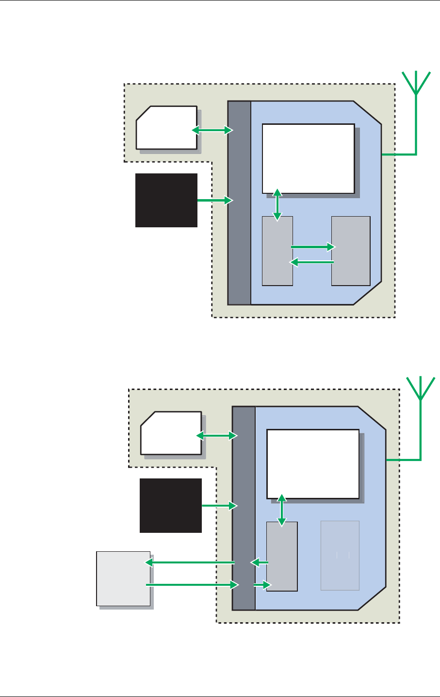
2.3 Control Terminals in a Communication System
Figures 2.1 and 2.2 illustrate the main blocks of a wireless communication
system using the Control Terminal. Figure 2.1 shows the communication
system when the script is embedded on the Control Terminal and figure
2.2 shows the communication system when a micro-controller is used.
They also show the communication principles of the system and the
interface between the Control Terminal and the application. The
definitions in the figures, as used elsewhere in this manual, are in
accordance with the recommendations of GSM 07.07.
• The MS (mobile station) represents the Control Terminal and SIM card.
The Control Terminal excluding SIM card, is known as the ME (mobile
equipment).
• The DTE (data terminal equipment) is the controlling application. This
can be either an external host or an internal embedded application.
• The DCE (data circuit terminating equipment) is the serial
communication interface of the MS.
2. GT47/GT48 CONTROL TERMINALS
9
LZ T 123 7605 P1C
Figure 2.1 Main Blocks in a Wireless System (embedded application)
Figure 2.2 Main Blocks in a Wireless System (external micro-controller)
SIM
MS
POWER
SUPPLY
GT47 / GT48
GSM
ENGINE
DCE DTE
STATUS &
RESPONSE
‘AT’ COMMAND
CONTROL
EMBEDDED
APPLICATION
SYSTEM CONNECTOR
GSM NETWORK
SIM
MS
POWER
SUPPLY
GT47 / GT48
GSM
ENGINE
DCE
SYSTEM CONNECTOR
GSM NETWORK
DTE
EXTERNAL
APPLICATION MS STATUS &
RESPONSE
‘AT’ COMMAND
CONTROL
D
T
E

2. GT47/GT48 CONTROL TERMINALS
10
LZ T 123 7605 P1C
In accordance with the recommendations of ITU-T (International
Telecommunication Union - Telecommunications Standardisation Sector)
V.24, the TE communicates with the MS over a serial interface.
The functions of the radio device follow the recommendations provided by
ETSI (European Telecommunications Standards Institute) and ITU-T.
ETSI specifies a set of AT commands for controlling the GSM element of
the Control Terminal; these commands are supplemented by Sony Ericsson
specific commands.
Note! To find out how to work with AT commands, see the GR47/GR48 AT
Commands Manual.
2.4 Main Features and Services
The Control Terminal performs a set of telecom services (TS) according to
GSM standard phase 2+, ETSI and ITU-T. The services and functions of
the Control Terminal may be implemented using customised applications
embedded on the device, or by AT commands over the RS232 serial
interface.
2.4.1 Types of Mobile Station
The GT47 and GT48 are dual band Control Terminals with the GSM radio
characteristics shown in the table below.
GT47 E-GSM900 GSM1800
Frequency Range (MHz) TX: 880-915
RX: 925-960
TX: 1710-1785
RX: 1805-1880
Channel spacing 200kHz 200kHz
Number of channels 174 carriers *8 time slots 374 carriers *8 time slots
Modulation GMSK GMSK
TX phase accuracy < 5º RMS phase error (burst) < 5º RMS phase error (burst)
Duplex spacing 45MHz 95MHz
Receiver sensitivity at
antenna connector
< –102dBm < –102dBm
Transmitter output power at
antenna connector
Class 4
2W (33dBm)
Class 1
1W (30dBm)
Automatic hand-over between EGSM 900 and GSM1800

2. GT47/GT48 CONTROL TERMINALS
11
LZ T 123 7605 P1C
2.4.2 Short Message Service
The Control Terminal supports the following SMS services:
• Sending; MO (mobile-originated) with both PDU (protocol data unit)
and text mode supported.
• Receiving; MT (mobile-terminated) with both PDU and text mode
supported.
• CBM (cell broadcast message); a service in which a message is sent to all
subscribers located in one or more specific cells in the GSM network
(for example, traffic reports). This feature is network dependent.
• SMS STATUS REPORT according to GSM 03.40.
• SMS COMMAND according to GSM 03.40.
The maximum length of an SMS message is 160 characters when using 7-
bit encoding. For 8-bit data, the maximum length is 140 characters. The
Control Terminal supports up to 6 concatenated messages to extend this
function.
2.4.3 Voice Services
The Control Terminal offers the capability of mobile originated and mobile
terminated voice calls, as well as supporting emergency calls. Multi-party,
call waiting and call divert features are available. Some of these features are
network-operator specific.
For the inter-connection of audio, the Control Terminal offers a balanced
4-wire analogue interface.
DTMF (Dual Tone Multi Frequency) is supported.
GT48 GSM850 GSM1900
Frequency Range (MHz) TX: 824-849
RX: 869-894
TX: 1850-1910
RX: 1930-1990
Channel spacing 200kHz 200kHz
Number of channels 124 carriers *8 time slots 299 carriers *8 time slots
Modulation GMSK GMSK
TX Phase Accuracy < 5º RMS phase error (burst) < 5º RMS phase error (burst)
Duplex spacing 45MHz 80MHz
Receiver sensitivity at
antenna connector
< –102dBm < –102dBm
Transmitter output power
at antenna connector
Class 4
2W (33dBm)
Class 1
1W (30dBm)
Automatic hand-over between GSM850 and GSM1900

2. GT47/GT48 CONTROL TERMINALS
12
LZ T 123 7605 P1C
The Control Terminal supports HR, FR and EFR vocoders. The GT48 also
supports the Adaptive Multi Rate (AMR) type of vocoder.
2.4.4 Data
The Control Terminal supports the following data protocols:
•GPRS (General Packet Radio Service).
The Control Terminal is Class B, which provide simultaneous
activation and attachment of GPRS and GSM services. GT47 is a GPRS
class 8 (4+1) enabled devices, which are capable of transmitting in one
timeslot per frame (up link), and receiving at a maximum of four
timeslots per frame (down link).
•CSD (Circuit Switched Data).
The Control Terminal GT47 is a capable of establishing a CSD
communication at 9.6kbps.
•HSCSD (High Speed Circuit Switched Data).
The Control Terminal supports HSCSD class 2 (2+1) communication,
with one timeslot per frame capacity in the up link and two timeslots
per frame capacity in the down link.
2.4.5 Fax
The Control Terminal allows fax transmissions to be sent and received by
commercial fax software installed on the application computer. Group 3 fax
Classes 1 and 2 are supported.
2.4.6 Supplementary Services
• Call forwarding
• Call hold, waiting and multiparty
• Calling/called number identification
• Advice of charge
• USSD
• Alternate line service
• Customer service profile
• Preferred networks
• Operator selection
• Network registration
• Call barring
• Call transfer

2. GT47/GT48 CONTROL TERMINALS
13
LZ T 123 7605 P1C
2.4.7 Serial Communication
The Control Terminal enables an end-to-end communication path to be
established between the telemetry/telematics application, either hosted
internal or connected externally, and a remote terminal or host, via the
GSM network. Once a path has been set up, voice or data communication
can take place. An RS232 9-signal serial interface is available via the
Control Terminal’s 15-way high density data connector.
This primary serial interface can be used to:
1.Co ntro l the G T47 via an external PC or micro-contro ller u si n g AT
com m ands;
2.Send and rec eive data.
The Control Terminal supports the full set of AT commands according to
GSM 07.05 and GSM 07.07. It also supports an extended set of Ericsson
proprietary AT commands to add extra functionality.
AT commands are used to operate the Control Terminal with a broad range
of functions including:
• configuring general parameters of the Control Terminal
• setting up and controlling communications to and from the GSM
network
• obtaining GSM network status information
Additionally the Control Terminal provides a second RS232 serial
interface, operating as a 4-signal and GND interface, with hardware flow
control (Rx, Tx, CTS and RTS). This 4-signal serial interface is controllable
via embedded applications and may be used to control external accessories
e.g. a GPS receiver.
For more detail on the AT commands supported by the Control Terminal
see GR47/GR48 AT Commands Manual.
2.4.8 Extended I/O Interface
The Control Terminal contains several general purpose, configurable,
input and output signals. Signals may be reconfigured by AT command or
by intrinsic function when using embedded applications.
• 1 analogue input
• 3 digital inputs
• 5 digital outputs
• + 4.8V DC output
In addition, 6 of the control signals on the primary RS232 interface can be
reconfigured for use as digital inputs or outputs if required.

2. GT47/GT48 CONTROL TERMINALS
14
LZ T 123 7605 P1C
The drivers controlling certain outputs have been designed to carry higher
currents than normal logic IOs. They can be used to activate or power
external devices, for example a switch or a relay.
A+4.8V output is available, if required, to power external devices.
2.4.9 Interfacing with the Control Terminal
The Control Terminal uses the following industry standard connectors;
• 15 pin high density socket (RS232 serial port and extended I/O
interface)
• RJ12 (plug-in power supply and extended I/O connector)
• RJ9 (handset audio connector)
• Integral SIM card reader
• FME male (antenna connector)

2. GT47/GT48 CONTROL TERMINALS
15
LZ T 123 7605 P1C
2.5 Service and Support
To contact customer support please use the details below:
Customer Support
Sony Ericsson Mobile Communications
1 Lakeside Road
Aerospace Centre
Farnborough
Hampshire
GU14 6XP
E-mail: modules.support@sonyericsson.com
or
modules.info@sonyericsson.com
Information about Sony Ericsson and its products is available on the
following web site:
http://www.SonyEricsson.com/M2M
2.6 Precautions
As a standalone item, the Control Terminal is designed for indoor use only.
To use outdoors it must be integrated into a weatherproof enclosure. Do
not exceed the environmental and electrical limits as specified in
“Technical Data”, page 49.

3. ABBREVIATIONS AND DEFINITIONS
16
LZ T 123 7605 P1C
3. Abbreviations and Definitions
Abbreviation Explanations
AMR Adaptive Multi Rate
CBM Cell Broadcast Message
CBS Cell Broadcast Service
CSD Circuit Switched Data
DCE Data Circuit Terminating Equipment
DTE Data Terminal Equipment
DTMF Dual Tone Multi Frequency
EFR Enhanced Full Rate
EMC Electro-Magnetic Compatibility
ETSI European Telecommunication Standards Institute
FR Full Rate
GPRS General Packet Radio Service
GSM Global System for Mobile Communication
High Side
Switch
Pin is driven high, to Vin, in the active state
HR Half Rate
HSCSD High Speed Circuit Switched Data
ITU-T International Telecommunication Union - Telecommunications
Standardisation Sector
Low Side
Switch
Pin is driven low in the active state. High state requires external pull up.
ME Mobile Equipment
MO Mobile Originated
MS Mobile Station
MT Mobile Terminated
PDU Protocol Data Unit
RLP Radio Link Protocol
RF Radio Frequency
RTC Real Time Clock
SIM Subscriber Identity Module
SMS Short Message Service

3. ABBREVIATIONS AND DEFINITIONS
17
LZ T 123 7605 P1C
TA Terminal Adapter
TE Terminal Equipment
TS Telecommunication Services
USSD Unstructured Supplementary Service Data
Abbreviation Explanations

Product Photo/Illustration
Integrating the Control
Terminal
19
LZ T 123 7605 P1C
4. Mechanical Description
4.1 Overview
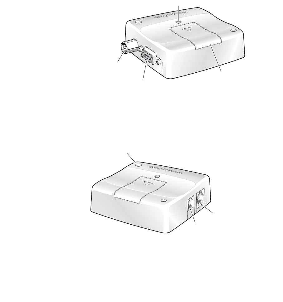
The pictures below show the mechanical design of the Control Terminal
along with the positions of the different connectors and mounting holes.
The Control Terminal case is made of durable PC/ABS plastic.
Figure 4.1 Control Terminal viewed from the left side
Figure 4.2 Control Terminal viewed from the right side
A
ntenna
connector
RS232 serial and
extended I/O connector
LE D
Access to
SIM card
Mounting hole (x2)
Audio
connector
Power supply and
extended I/O connecto
r

4. MECHANICAL DESCRIPTION
20
LZ T 123 7605 P1C
Please note the following:
• Mounting holes positioned at two of the corners make it possible to
securely bolt the Control Terminal into your application.
• Keypad, display, microphone, speaker and battery are not part of the
Control Terminal.
• The SIM card is mounted in the Control Terminal.
• The pins and electrical characteristics of the Control Terminal’s various
connectors are described in
“Electrical Description”, page 22.
• Information about the antenna connector is found in
“Antenna Connector”, page 33.
4. MECHANICAL DESCRIPTION
21
LZ T 123 7605 P1C
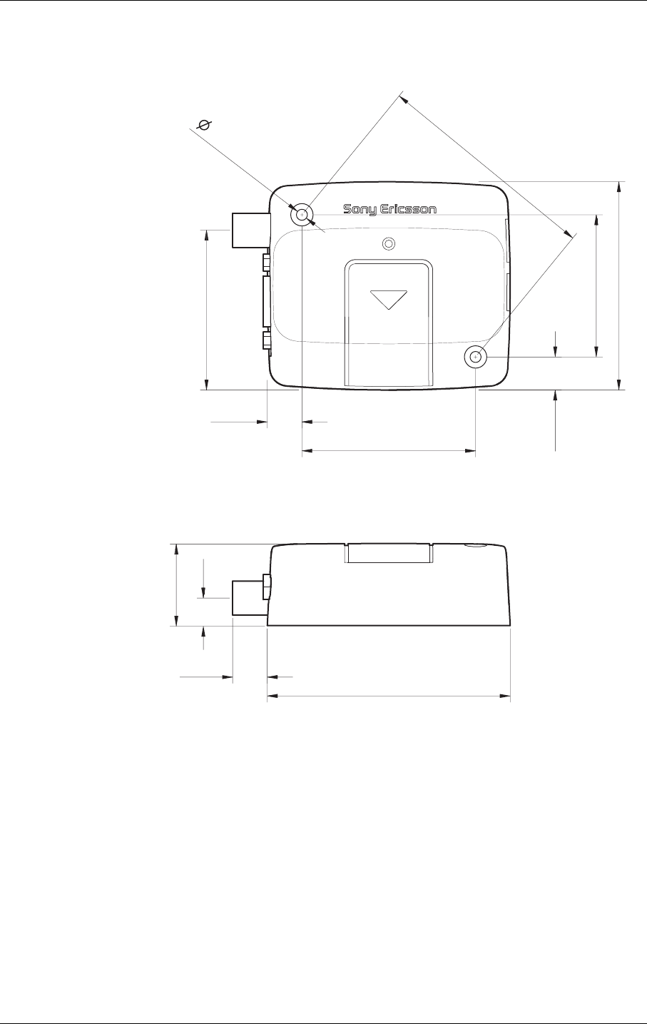
4.2 Physical Dimensions
Measurements are given in millimetres. See also “Technical Data”, page 49.
7 1.5
66.4
77.4
26.2
11.0
55.3
45.3
10.6
11.0
9.0
51.0
(x2)
3.5
5. ELECTRICAL DESCRIPTION
22
LZ T 123 7605 P1C
5. Electrical Description
All electrical connections to the module are protected in compliance with
the standard air (8kV) and contact (4kV) Electrostatic Discharge (ESD)
tests, of EN 61000-4-2.
The module uses the following industry standard connectors:
• High density 15 pin (RS232 serial and extended I/O interface)
• RJ12 6-way (power supply and extended I/O connector)
• RJ9 4-way (handset connector)
• SIM card reader
• FME male coaxial jack (antenna connector)
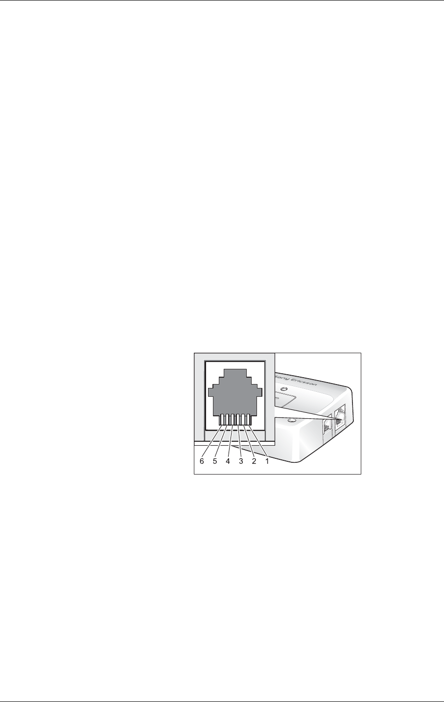
5.1 Power Supply and Extended I/O Connector
An RJ12 6-way connector, as shown and described below, serves as a means
of supplying and controlling d.c. power to the modem. Additionally there
are several extended input/output signals available that can be used to
control or interface external systems and devices.
General signal description:
1 VIN
2 OUT-2
3 IN-1
4 TO_IN
5 OUT-1
6 GND

5. ELECTRICAL DESCRIPTION
23
LZ T 123 7605 P1C
The power connector electrical characteristics are listed below:
Note! Signal OUT-2 on the RJ12 connector is switched in parallel to signal
OUT-4 on the 15-pin high density socket. The individual output signals
are generated by two different low side switches inside the module driven
from a common control signal.
5.1.1 Power Supply Interface
The supply voltage VIN and GND are protected against polarity reversal
and over voltage.
The Control Terminal switches on automatically once the VIN voltage is
applied.
Note! The Control Terminal will not switch on if TO_IN is shorted to ground
when the dc supply is applied.
Note! For more information on switching the Control Terminal on and off please
see section “Operation”, page 39
Note! Please be aware that the total current carried via either the VIN or GND
pins will be the sum of the intrinsic power consumption of the Control
Terminal and any drive current supplied via OUT-1 or OUT-2 (or other
IOs). The current on either of the VIN or GND pins must not exceed 1.5A.
Caution! It is recommended that the system integrator provides appropriate fusing
otherwise the Control Terminal may be damaged. See “Current
Consumption with external +4.8V Supply Active”, page 53 for more
details.
Pin Signal Dir Limits Description
1 VIN I5 to 32V Positive power input
2 OUT-2 O 32V, 0.25A Low side switch, short circuit protected
3IN-1 I–0.5 to 32V Digital Input
VIH > 3V, VIL < 2.8V
Internal Pull Down of 40kΩ
4 TO_IN I –0.5 to 32V Active low control line used to switch
the GT47 off/on.
VIH > 5V, VIL < 2V
Power off/on: t > 0.2s
Internal Pull Up to VIN of 20kΩ
5OUT-1 O VIN, 0.4A High side switch, short circuit protected
6 GND I - Negative power (ground) input and
return path for TO_IN and the extended
inputs and outputs

5. ELECTRICAL DESCRIPTION
24
LZ T 123 7605 P1C
Extended I/O Signals
Digital Inputs
The digital input IN-1 is available on pin 3 of the RJ12 connector. Its state
is detected by IO5 of the embedded Radio Device engine, see Control
Terminal-Radio Device signal cross reference table, page 30.
The distinction between low level and high level signals is at the voltage
level of 3 V. Voltages above 3 V are detected as high level voltages and
voltages below 2.8 V are detected as low level.
Digital Outputs
The RJ12 power supply connector has two different output drivers:
• OUT-1 is driven by a high side switch that applies VIN to pin 5 of the
RJ12 connector. IO1 of the embedded radio device is used to activate
the OUT-1 signal, see Control Terminal - radio device signal cross
reference table, page 30.
• OUT-2 is driven by a low side switch that shorts pin 2 of the RJ12
connector to ground when activated. IO3 of the embedded Radio
Device engine is used to activate OUT-2, see Control Terminal - Radio
Device signal cross reference table, page 30.
VIN Monitoring
The voltage, VIN, can be monitored internally by the Control Terminal, for
example if the Control Terminal is supplied from an external battery.
ADC1 on the Radio Device is used for this purpose, see Control Terminal-
Radio Device signal cross reference table, and is calibrated to operate in the
voltage range 0 – 31.875 V. The resolution of the 8 bit converter, ADC1,
provides a measurement accuracy of approximately 3%.
IMAGE -TBD
5. ELECTRICAL DESCRIPTION
25
LZ T 123 7605 P1C
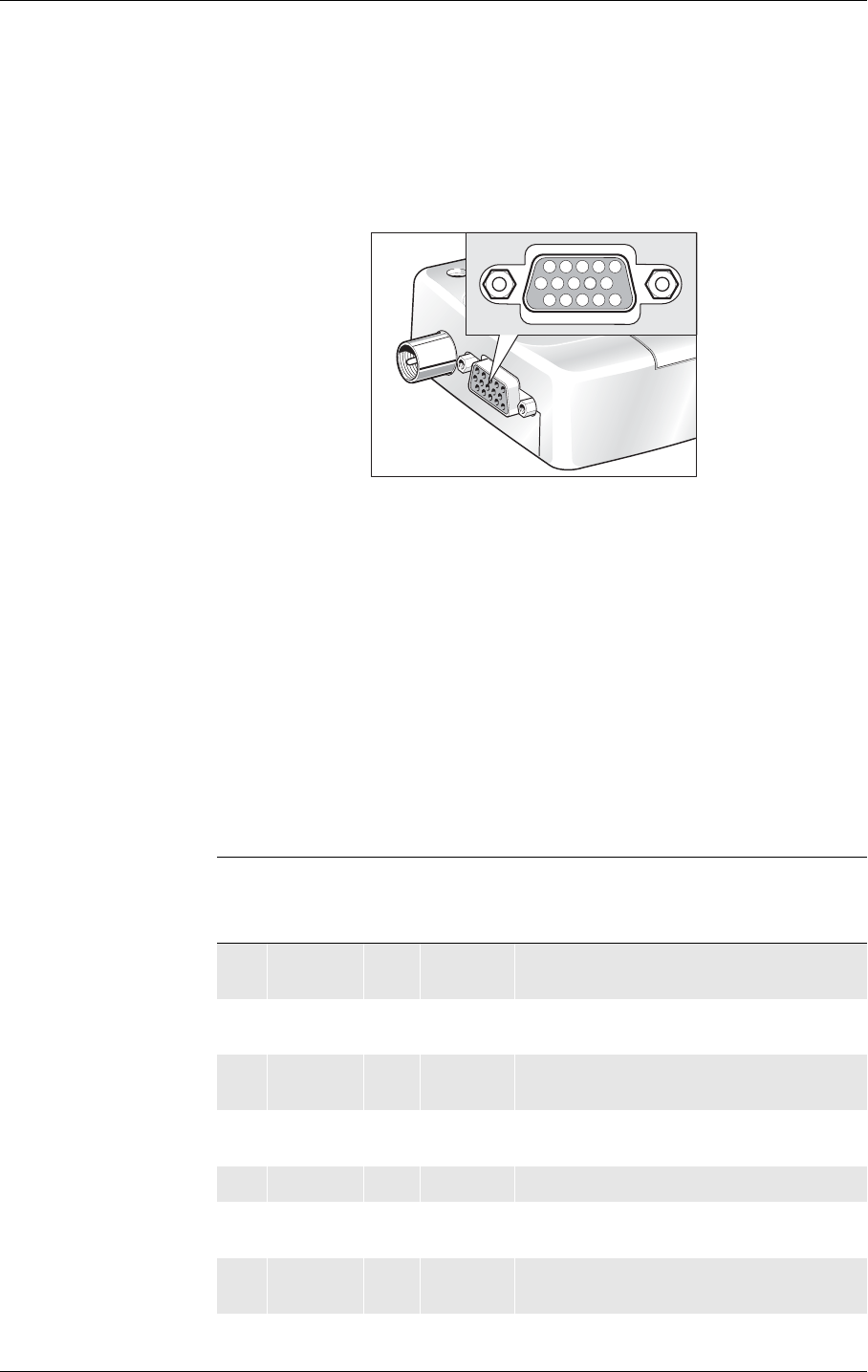
5.2 RS232 Serial and Extended I/O Interface
The Control Terminal supports a standard 9 signal RS232 serial interface
(EIA/TIA 574) on the 15 pin high density connector together with a range
of configurable I/Os including a second 4-wire logic level RS232 interface.
Signals that support an alternative configuration can be reconfigured using
the appropriate AT command (e.g. AT+E2IO) or via an intrinsic function
if using an embedded application.
Note! When reconfiguring a Control Terminal signal, via AT command or
intrinsic function, the corresponding Radio Device signal name must be
used, see Control Terminal-Radio Device signal cross reference table,
page 30.
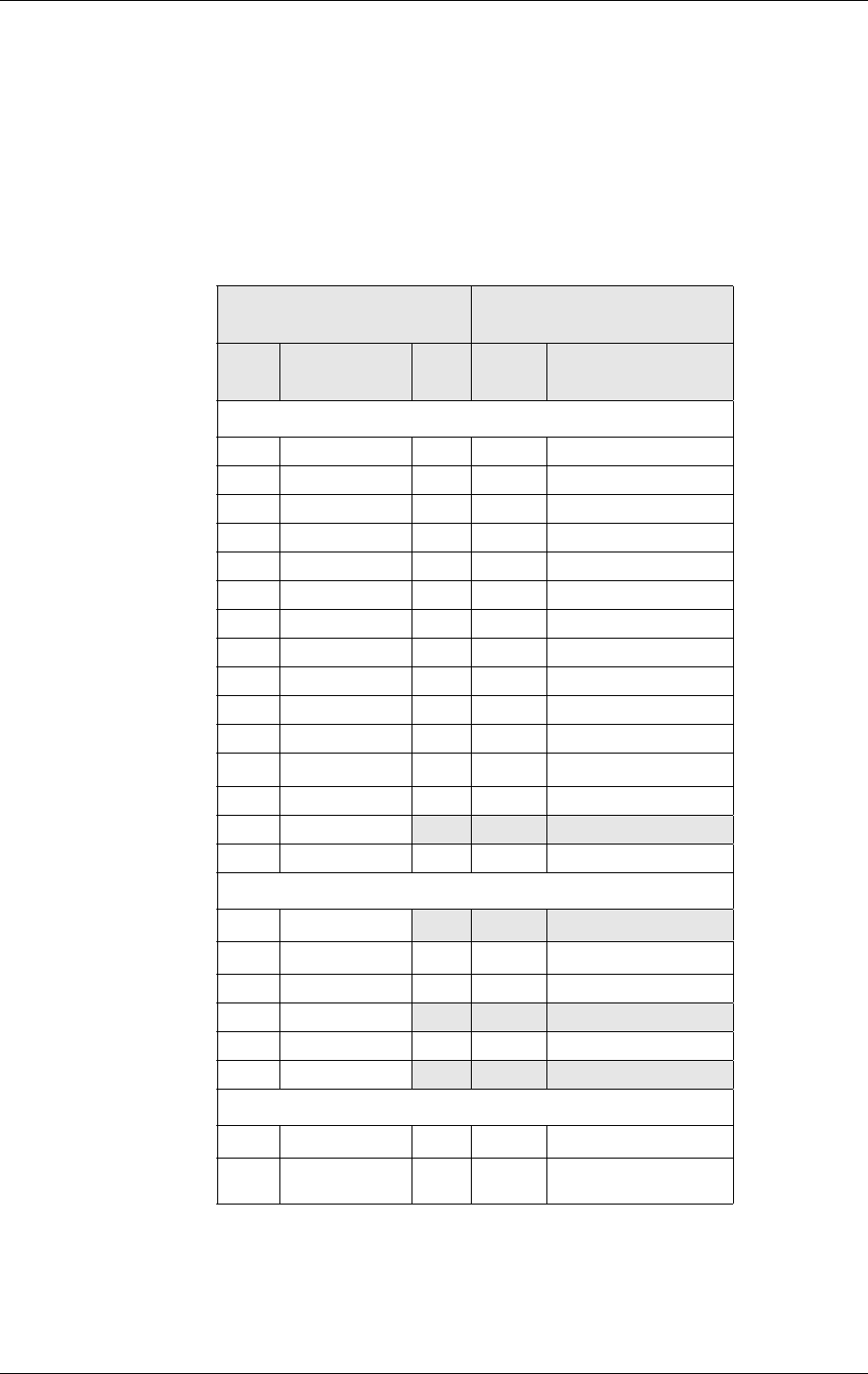
The electrical characteristics of the serial port signals are shown below:
12 OUT-4
7 RTS
2 RD
13 DTR
8 CTS
3 TD
123
678
13 14
10
45
9
11 12 15
11 IN-2
6 DSR
1 DCD
15 ANA_IN
10 RI
5 OUT-3
14 GND
9 4.8V
4 IN-3
Pin Control
Terminal
Signal
Dir Max.
Voltage
limits
Description
1DCD O±13.2V RS232 signal
Data carrier detect Vout ≥ ±5V
2 RD O ±13.2V RS232 signal:
Received data Vout ≥ ±5V
3TD I± 25V RS232 signal:
Transmitted data VIL < 0.6V, VIH > 2.4V
4 IN-3 I -0.5 to 32V Digital input VIH > 3V, VIL < 2.8V
PullDown with 40kΩ
5OUT-3 O32V, 0.25A low side switch, short circuit protected
6 DSR O ±13.2V RS232 signal:
Data set ready Vout ≥ ±5V
7RTS I±25V RS232 signal:
Request to send VIL < 0.6V, VIH > 2.4V

5. ELECTRICAL DESCRIPTION
26
LZ T 123 7605 P1C
5.2.1 Standard RS232 Serial interface and Signals
The module supports a standard RS232 serial interface (EIA/TIA 574) via
its 15 pin high density connector, shown above.
5.2.2 Serial Data
The Control Terminal supports the standard data character format of 1
start bit, 8 bit data, no parity plus 1 stop bit, in total 10 bits per character.
In line with serial communication terminology the module is the data
circuit-terminating equipment (DCE) and the external application or
computer is the data terminating equipment (DTE).
5.2.3 Serial Data Signals - RD, TD
The default baud rate is 9.6kbps, however higher bit rates up to 230.4kbps
are supported and can be set by AT commands. At start-up the module
transmits and receives data at the default rate of 9.6kbps in either standard
AT mode or binary mode (the first received data - AT or binary format -
determines the operating mode).
Serial Data From GT47 (RD) Pin 2
RD is an output signal that the Control Terminal uses to send data to the
external application.
8 CTS O ±13.2V RS232 signal:
Clear to send Vout ≥ ±5V
94.8V O0 to +4.8V,
75mA
Voltage supply for external devices
Supply voltage +4.8V, max. current 75mA
10 RI O ±13.2V RS232 signal:
Ring indicator Vout ≥ ±5V
11 IN-2 I-0.5 to 32V Digital input VIH > 3V, VIL < 2.8V
PullDown with 40kΩ
12 OUT-4 O 32V, 0.25A low side switch, short circuit protected
13 DTR I±25V RS232 signal:
Data Terminal Ready VIL < 0.6V, VIH > 2.4V
14 GND I - Ground connection and return path for
the extended inputs/outputs
15 ANA_IN I-0.5 to 32V Analog input measurement range: 0 to
12.75V
Pin Control
Terminal
Signal
Dir Max.
Voltage
limits
Description

5. ELECTRICAL DESCRIPTION
27
LZ T 123 7605 P1C
Serial Data To Control Terminal (TD) Pin 3
TD is an input signal, used by the external application to send data to the
Control Terminal.
5.2.4 Control Signals - RTS, CTS, DTR, DSR, DCD, RI
Request to Send (RTS) Pin 7
Used to condition the Control Terminal for data transmission. The default
level is inactive by internal pull down.
The exact behaviour of RTS is defined by an AT command. Software or
hardware flow control can be selected. Hardware flow control is the default
selection.
The application must pull RTS high to enable transmission from the
Control Terminal.
Clear To Send (CTS) Pin 8
CTS indicates that the Control Terminal is ready to transmit data. The
default level is high. You can define the exact behaviour of CTS through an
AT command, and can select software or hardware flow control.
Data Terminal Ready (DTR) Pin 13
DTR indicates that the DTE is ready to send and receive data. It also acts
as a hardware ‘hang-up’, terminating calls when switched low. The signal
is active high. You can define the exact behaviour of DTR with an AT
command.
Data Set Ready (DSR) Pin 6
An active DSR signal is sent from the Control Terminal to the application
(DTE) to confirm that a communications path has been established. DSR
has two modes of operation, use the AT command AT&S to set the mode.
Data Carrier Detect (DCD) Pin 1
DCD indicates that the Control Terminal is receiving a valid carrier (data
signal) when high. You can define the exact behaviour of DCD with an AT
command.
Ring Indicator (RI) Pin 10
RI indicates that a ringing signal is being received by the Control Terminal
when high. You can define the exact behaviour of RI with an AT
command.

5. ELECTRICAL DESCRIPTION
28
LZ T 123 7605 P1C
Alternative Configuration
It is possible to reconfigure one or more of the signals in this section (RTS,
CTS, DTR, DSR DCD and RI) to be used as digital inputs or outputs if the
full RS232 serial interface is not required. Configuration is achieved using
AT command (AT+E2IO) or via embedded application intrinsic functions,
please refer to Control Terminal-Radio Device signal cross reference table,
page 30.
To be reconfigured as a digital IO, each signal must retain the direction and
the logic voltage levels attributed to it when used as an RS232 signal. For
example DSR can only be reconfigured as a digital output with Vout ≥ ±5V.
5.2.5 Extended I/O Signals
Please refer to Control Terminal-Radio Device signal cross reference table,
page 30, for more information on the relationship between signal names
and pin numbers of the Control Terminal and the embedded Radio Device
engine.
Digital Inputs Pin 4 & 11
Digital inputs IN-2 and IN-3 are available on the HD15 connector via pins
11 and 4 respectively. The inputs are detected via signals IO4 and IO7 of
the embedded Radio Device engine.
Note! As an alternative configuration signals IN-2 and IN-3 can be used to
support a second RS232 serial interface as RTS-2 and TD-2. Further
information is given below.
Analog Input Pin 15
The signal ANA_IN can be used for measuring analog input values in the
range 0 to 12.75V. ADC2 of the embedded GR47 is used to detect
ANA_IN.
The resolution of the converter is 8 bit with an measurement accuracy of
about 3%.
The input impedance of the ANA_IN pin is 50 kΩ.
Digital Outputs Pin 5 & 12
Digital outputs OUT-3 and OUT-4 are available on the HD15 connector
via pins 5 and 12 respectively. The outputs are controlled via signals IO8
and IO3 of the embedded Radio Device engine.
Signal OUT-4 on the HD15 connector is switched in parallel to signal
OUT-2 on the RJ12 connector. The individual output signals are
generated by two different low side switches inside the terminal driven
from the common control signal, IO3. All Control Terminal output signals

5. ELECTRICAL DESCRIPTION
29
LZ T 123 7605 P1C
driven by low side switches return to open circuit when deactivated. This
allows the external application hardware to determine the desired logic
voltage levels with the appropriate pull-up.
The output drivers are low side switches which short the pin to GND if
they are activated.
Note! As an alternative configuration signals OUT-3 and OUT-4 can be used to
support a second RS232 serial interface as RD-2 and CTS-2. Further
information is given below.
+4.8V Output Supply Pin 9
There is a voltage regulator implemented inside the module that is capable
of supplying an external voltage source of +4.8V with a maximum current
of 75 mA.
The voltage source can be switched on/off with the DAC signal of the
internal Radio Device GSM engine.
By default the voltage source is switched on. A high level of 2.75V at the
DAC output of the Radio Device GSM engine will switch the voltage
source off.
Note! The +4.8V source may be switched on/off via an embedded or external
application and so may be used as an optional digital output with levels of
+4.8V and open circuit.
5.2.6 Second RS232 Serial Interface
IN-3 and OUT-3 can be automatically reconfigured as signals TD-2 and
RD-2, of a second serial interface, by enabling UART3 of the internal
Radio Device. UART 3 may be enabled using AT command or intrinsic
function.
In addition, IN-2 and OUT-4 can be automatically reconfigured as signals
RTS-2 and CTS-2 of the second serial interface by enabling hardware flow
control for UART3 on the internal Radio Device. Hardware flow control
can be enabled using intrinsic function only.
Note! The signal level thresholds for each of the digital inputs of the second serial
interface are: 3V<VIH<32V and VIL< 2.8V.
An external RS232 transceiver component may be used to convert the serial
interface to standard RS232 electrical levels. The Control Terminal's +4.8
V output can be used to provide power for the transceiver.
5. ELECTRICAL DESCRIPTION
30
LZ T 123 7605 P1C
5.2.7 Relationship between Control Terminal and Radio Device signals
When reconfiguring a Control Terminal signal, via AT command or
intrinsic function, the corresponding Radio Device signal name must be
used, see the Control Terminal-Radio Device signal cross reference tables
overleaf.
Control Terminal - Radio Device Signal Cross-reference Table A
† IO3 o n the em bedded Radio Device pro vides the com m on contro l si g n al
for both C o ntro l Term inal sig nals OUT-2 and OUT-4 .
Control Terminal (CT) Relationship to the
Radio Device (RD) engine
CT Pin CT Primary
Signal
Dir. RD Pin Corresponding RD
Signal
HD15 Connector
1 DCD O 38 DCD
2RD O42 RD
3TD I41TD
4IN-3 I 43 IO7
5OUT-3 O44 IO8
6 DSR O 32 DSR
7 RTS I 39 RTS
8 CTS O 40 CTS
9 +4.8V O 20 DAC
10 RI O 36 RI
11 IN-2 I 24 IO4
12 OUT-4 O 23 IO3†
13 DTR I 37 DTR
14 GND
15 ANA_IN I 27 ADC2
RJ12 Connector
1V
IN
2OUT-2 O23 IO3†
3IN-1 I13I05
4TO_IN
5OUT-1 O21 IO1
6GND
Control Terminal Internal Function
VIN Monitoring I26ADC1
Power Save
Mode
O22 IO2
5. ELECTRICAL DESCRIPTION
31
LZ T 123 7605 P1C
Control Terminal - Radio Device Signal Cross-reference Table B
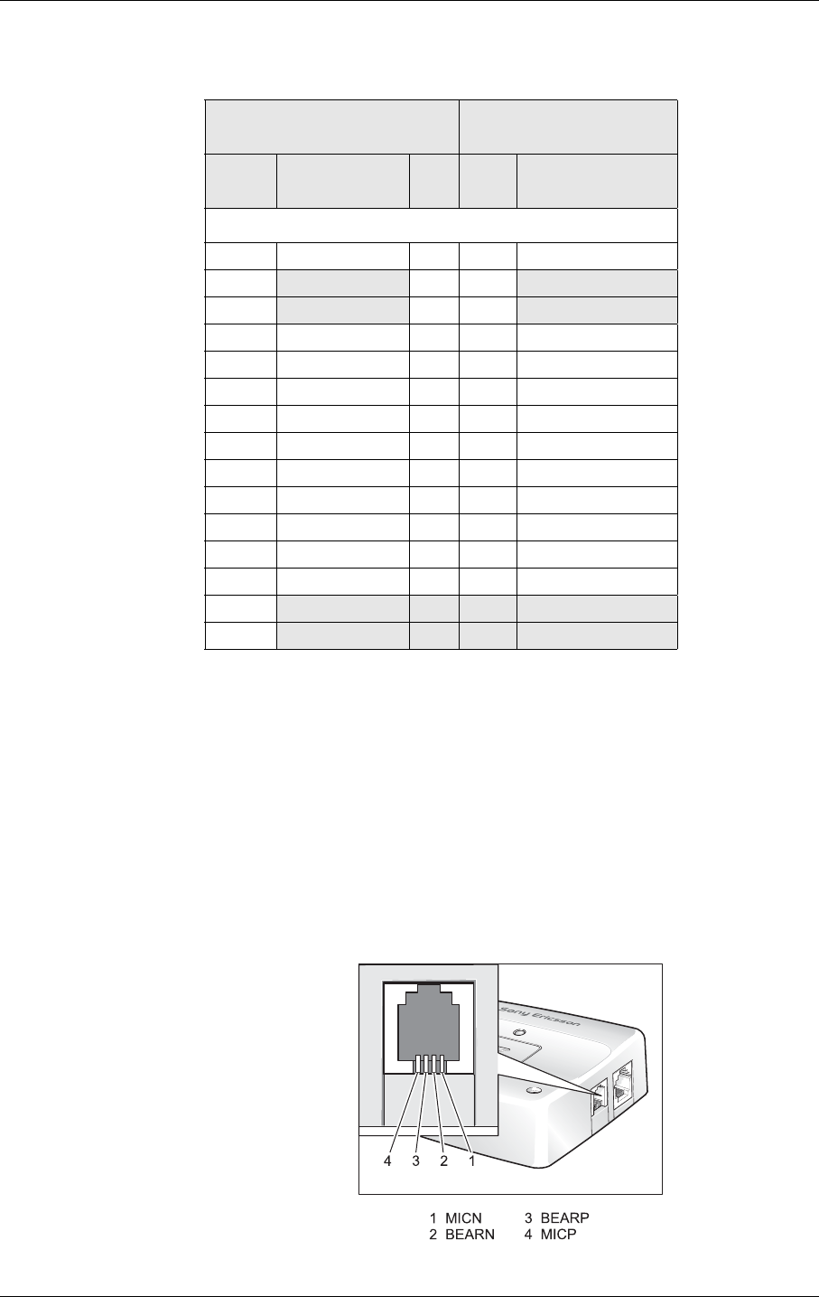
5.3 Audio Connector
A 4-way RJ9 connector, as shown below, allows a telephone handset to be
plugged into the Control Terminal, giving access to the microphone and
earpiece signals. The connector may also be used to drive other analogue
audio sub-systems or devices.
The module is configured to work with a range of handsets. If necessary,
changes can be made to the characteristics of the audio interface by sending
the Control Terminal appropriate AT commands.
Control Device (CT) Relationship to
Radio Device (RD) engine
CT Pin CT Alternative
signal
Dir. Pin Corresponding RD
Signal
HD15 Connector
1OUT-6 O38O1
2I42
3O41
4TD-2 I43TD3
5RD-2 O44RD3
6OUT-7 O32O3
7IN-4 I39IO9
8OUT-8 O40O4
9OUT-5 O20DAC
10 OUT-9 O 36 O2
11 RTS-2 I 24 IO4
12 CTS-2 O 23 IO3
13 IN-5 I 37 IN1
14
15

5. ELECTRICAL DESCRIPTION
32
LZ T 123 7605 P1C
Audio signal descriptions are listed below:
MICP and MICN are balanced differential microphone input signals.
These inputs are compatible with an electret microphone.
BEARP and BEARN are the speaker output signals. These are
differential-mode outputs. The electrical characteristics are given in the
table below.
The following table shows the ear piece impedances that can be connected
to BEARP and BEARN.
Pin Signal Dir Description
1MICN IMicrophone negative input
2 BEARN O Earpiece negative output
3BEARP OEarpiece positive output
4 MICP I Microphone positive input
Parameter Limit
Output level (differential) ≥4.0Vpp
Output level (dynamic load = 32Ω)≥2.8Vpp
Distortion at 1kHz and maximum output level ≤5%
Offset, BEARP to BEARN ±30mV
Ear piece mute switch attenuation ≥40dB
Ear piece model Impedance Tolerance
Dynamic ear piece [32Ω + 800µH] // 100pF ±20%
Dynamic ear piece [150Ω + 800µH] // 100pF ±20%
Piezo ear piece 1kΩ + 60nF ±20%
5. ELECTRICAL DESCRIPTION
33
LZ T 123 7605 P1C
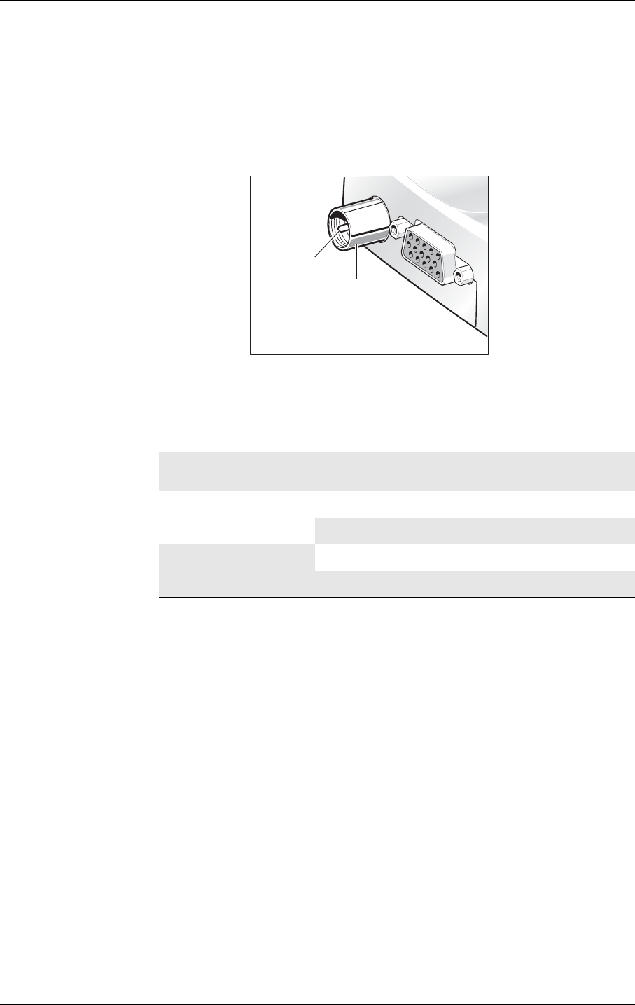
5.4 Antenna Connector
The antenna connector allows transmission of radio frequency (RF) signals
between the Control Terminal and an external customer-supplied antenna.
The module is fitted with a 50Ω, FME male coaxial jack as shown below.
The table below shows the antenna electrical characteristics:
For information on antenna refer to “Antenna”, page 46.
Parameter Limit Description
Nominal impedance 50Ω (SWR better than
2.5:1)
Output Power 2 Watt peak (Class 4) EGSM 850/EGSM 900
1 Watt peak (Class 1) GSM1800/GSM 1900
Static Sensitivity Better than –102dBm EGSM 850/ EGSM 900
Better than –102dBm GSM1800/ GSM 1900
RF Signal
GND
5. ELECTRICAL DESCRIPTION
34
LZ T 123 7605 P1C
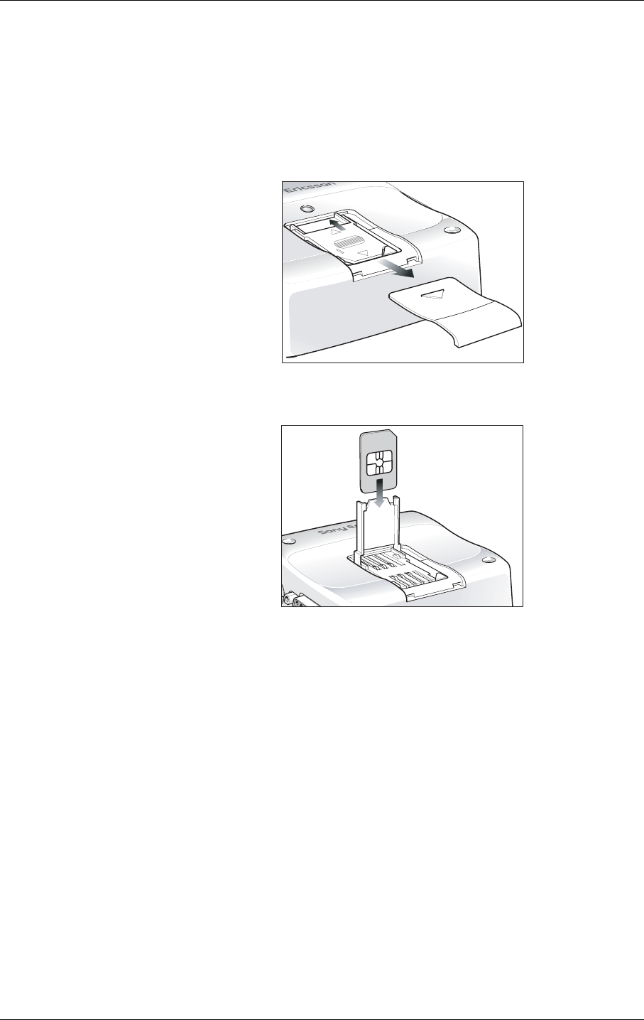
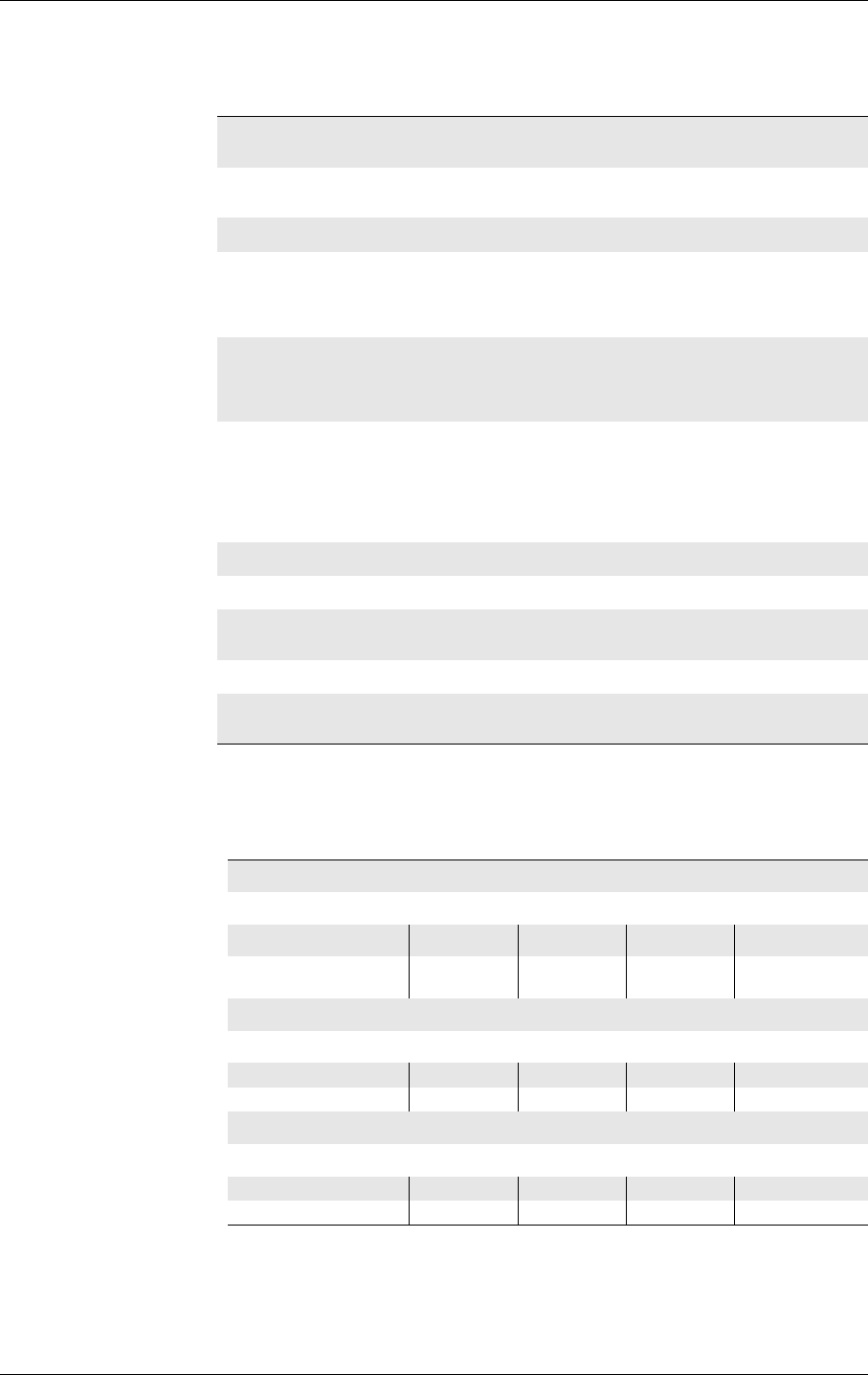
5.5 SIM Card Reader
The module is fitted with a SIM card reader designed for 3V and 5V SIM
cards. It is the flip-up type which is lockable in the horizontal position and
is accessed through a removable panel as shown below.
The SIM card reader incorporates a SIM presence switch which detects
whether a SIM card is inserted. The full operation of the Control Terminal
relies on a SIM card being inserted.
Caution! Some Control Terminal functionality may be lost if you try to operate it
without a SIM card.
The SIM presence switch also ensures that when a SIM card is inserted or
removed the unit is reset, as long as the Control Terminal is switched ON.
Loggin with the SIM In
TBA
Logging with the SIM Out
TBD

5. ELECTRICAL DESCRIPTION
35
LZ T 123 7605 P1C
5.6 Real Time Clock
The module contains a real time clock (RTC) to maintain accurate
timekeeping and to enable “timestamping” of messages.
The RTC is powered all the time that the Control Terminal is turned on.
When the Control Terminal is powered off, a storage energy device within
the module provides back-up power to maintain the RTC for several hours
- please contact Sony Ericsson Customer Support for more information.
The RTC back-up is fully charged after approximately 10 hours with the
control terminal turned on. Once fully charged the RTC back-up will
maintain the Real Time Clock for at least 8 hours.
5.7 Software Updates
It is possible, and sometimes necessary, to update the module software.
Updates must be carried out by a Sony Ericsson approved technician. Please
contact your supplier for details (see “Service and Support”, page 9).

6. EMBEDDED APPLICATIONS
36
LZ T 123 7605 P1C
6. Embedded Applications
The module has the capability to store, and run customer written code in
the form of a script during the processors idle time, through the use of an
on board interpreter.
6.1 Features
Main features of embedded applications are as follows.
• C based scripting language (Sony Ericsson specific)
• Over the air upgrade of scripts (NOT GSM software)
• Library of intrinsic functions
• Two radio device scripts can be stored, but only one can run at any one
time.
6.2 Implementation
The module has up to 44kbytes of space available for storage of two scripts
in the scripting language and 25kbytes of operating RAM. Structures
included in this language are:
• If - then - else statements
• While loops
•For loops
All hardware interfaces that are normally available to the module through
the AT commands are available to the embedded application. Further
drivers have been written such as M bus and I2C for use by the embedded
application (EA) through the use of the I/O pins.
6.2.1 Limitations
Since the module is processing the script using its own memory,
limitations are placed onto the scripts that are run.
• A direct comparison cannot be made to a fully compiled C program in
terms of size but a gauge of script size is that if each line were 128
characters long in the script then the script could be 350 lines long.
• Processing power is something that needs to be considered as the script
is run as a low priority process within the software. However, controller
mode stops GSM operation and provides all the processing power for
the script to be run. See the M2m Power Application Guide for more
details.
• Code cannot be ported directly from an existing application and loaded
directly onto the radio device. It must be re written in the Sony
Ericsson Mobile script language so that the radio device interpreter can
function correctly.

6. EMBEDDED APPLICATIONS
37
LZ T 123 7605 P1C
6.2.2 M2mpower IDE (Integrated Developers Environment)
The IDE is a windows based package which allows the user to write,
simulate, debug and download the application into a radio device with the
embedded application (EA) software. The standard version is designed to
run on Windows XP and 2000, other versions are available for 98 if
required.
A M2m Power application guide is available for implementing applications
using the developers kit and the embedded application (EA) functionality.
This is a required package to be able to implement an embedded
application (EA).
For further information please contact SEM customer support.

7. TCP/IP STACK
38
LZ T 123 7605 P1C
7. TCP/IP Stack
An on board IP/TCP/UDP stack has been integrated into the software
negating the need for the customer to implement one in their own code
base.
This is available through the embedded applications (see previous section)
using intrinsic functions and also through AT commands (see GR47/GR48
AT commands manual).
7.1 Implementation
The following types of commands allow various functions:
• Open/closing IP connection - Negotiates/closes a dynamic IP address
with the web server.
• Send/Receive TCP packets - Performs all TCP operations to send and
receive packets.
• Send/Receive UDP packets - Performs all UDP operations to send and
receive packets.
• Resolve URL to an IP address - Similar to lookup command in DOS
When the unit is set up and controlled using the embedded applications
either the embedded applications or an external application can generate
data to be sent and pass it to the radio device for transmission.
This effectively provides a transparent communication link to an internet
server from the application over GPRS.

8. OPERATION
39
LZ T 123 7605 P1C
8. Operation
8.1 Switching On the Control Terminal
The Control Terminal is turned ON automatically once DC power is
applied. If the Control Terminal is turned OFF, using one of the methods
described in 8.2, the Control Terminal can be turned ON again through
one of two methods:
• pull signal TO_IN to ground for t >0.2s, then release.
• activate the main RS232 control line DTR, low to high for >0.2s
The Control Terminal is fully operational after 4 seconds. Logging onto a
network may take longer than this and is outside the control of the Control
Terminal.
Note! The Control Terminal will not switch on if TO_IN is shorted to ground
when the dc supply is applied.
8.2 Switching Off the Control Terminal
There are two ways to switch off the Control Terminal as described below.
• Use the appropriate AT command (AT+CFUN);
• pull signal TO_IN to ground for t >0.2s, then release.
8.3 Resetting the Control Terminal
A full system reset, independent of the status of the software, may be
applied to the Control Terminal as follows:
• assert HR_IN high for > 3.5s.
8.4 Operating States/LED
The Control Terminal has a green LED, as depicted below, which is used
to indicate various operating states. These states are described in following
table.
LE D

8. OPERATION
40
LZ T 123 7605 P1C
8.5 Power Save
The Control Terminal can power down the main RS232 IC when not
needed in order to minimise power consumption. The IC is powered up
automatically at start-up but can be powered down by setting the output
of IO2 on the embedded Radio Device (pin22) to low via AT command or
embedded application. Once powered down, the IC can be woken up by
setting the output of IO2 high on the Radio Device via AT Command.
Even when powered down the IC is able to pass a DTR signal received on
the serial interface. Therefore an embedded application that monitors
DTR, while the IC is powered down, can be made to wake up the IC, if a
signal is received, by setting IO2 on the Radio Device high.
8.6 Controller Mode
The Control Terminal, when powered up, will normally start up its GSM
signalling software and look to register on the GSM network. Any
embedded application script runs as a background process as and when the
GSM software is idle. A feature available via embedded applications allows
the Control Terminal to be placed in ‘controller mode’ whereby the Control
Terminal powers up with a minimal subset of radio functionality. The
GSM signalling software is halted and the embedded applications script
has full control of the processor.
Controller mode allows an application to run with more predictable
response times.
Operating state LED
After switching on the Control Terminal On after 4s
Control Terminal switched off or power removed from the
module
Off
Standby or talk Flashing
No network, network search, no SIM card, no PIN entered On

9. SAFETY AND PRODUCT CARE
41
LZ T 123 7605 P1C
9. Safety and Product Care
Please read the information in this section and the information in
“Installation of the Control Terminal”, page 44, before starting your
integration work.
9.1 Safety Instructions
PLEASE READ THESE SAFETY INSTRUCTIONS AND KEEP A
COPY OF THEM.
• Always ensure that use of the Control Terminal is permitted. The
Control Terminal may present a hazard if used in proximity to personal
medical electronic devices. As a rule, the Control Terminal must not be
used in hospitals, airports or planes.
• Never use the Control Terminal at a gas station, refuelling point,
blasting area or in any other environment where explosives may be
present.
• Operating the Control Terminal close to other electronic devices, such
as antennas, television sets, and radios may cause electromagnetic
interference.
• This product is intended to be used with the antenna or other radiating
element at least 20cm away from any part of the human body. In
applications where this rule cannot be applied, the application designer
is responsible for providing the SAR measurement test report and
declaration.
• You are responsible for observing your country's safety standards, and
where applicable, the relevant wiring rules.
9.2 General Precautions
• The Control Terminal as a stand alone item is designed for indoor use
only. To use outside it must be integrated into a weatherproof enclosure.
Do not exceed the environmental and electrical limits as specified in
“Technical Data”, page 49.
• Avoid exposing the Control Terminal to lighted cigarettes, naked
flames or to extreme hot or cold temperature.
• Never try to dismantle the Control Terminal yourself. There are no
components inside the Control Terminal that can be serviced by the
user. If you attempt to dismantle the Control Terminal, you may
invalidate the warranty.
• The Control Terminal must not be installed or located where the
surface temperature of the plastic case may exceed 85°C.
• All cables connected to the Control Terminal must be secured or
clamped, immediately adjacent to the Control Terminal's connectors, to

9. SAFETY AND PRODUCT CARE
42
LZ T 123 7605 P1C
provide strain relief and to avoid transmitting excessive vibration to the
Control Terminal in the installation.
• Ensure the d.c. cable, supplying power to the Control Terminal, does
not exceed 3 metres. For longer distances please contact Sony Ericsson
Service and Support.
• To protect power supply cables and meet the fire safety requirements
when the unit is powered from a battery or a high current supply,
connect a fast 1.5A fuse in line with the positive supply. An appropiate
fuse should be used see section “Power Supply”, page 45
• Do not connect any incompatible component or product to the Control
Terminal.
Note! Sony Ericsson may refuse warranty claims where evidence of product
misuse is found.
9.3 SIM Card Precautions
• Before handling the SIM card in your application, ensure that you are
not charged with static electricity. Use proper precautions to avoid
electrostatic discharges.
• When the SIM card hatch is opened, the SIM card connectors lie
exposed under the SIM card holder.
Caution! Do not touch these connectors! If you do, you may release an electrical
discharge that could damage the Control Terminal or the SIM card.
• When designing your application, the SIM card’s accessibility should
be taken into account. We always recommend that you have the SIM
card protected by a PIN code. This will ensure that the SIM card cannot
be used by an unauthorized person.
9.4 Antenna Precautions
• If the antenna is to be mounted outside, consider the risk of lightning.
Follow the instructions provided by the antenna manufacturer.
• Never connect more than one Control Terminal to a single antenna. The
Control Terminal can be damaged by radio frequency energy from the
transmitter of another Control Terminal.
• Like any mobile station, the antenna of the Control Terminal emits
radio frequency energy. To avoid EMI (electromagnetic interference),
you must determine whether the application itself, or equipment in the
application’s proximity, needs further protection against radio emission
and the disturbances it might cause. Protection is secured either by
shielding the surrounding electronics or by moving the antenna away
from the electronics and the external signals cable.

9. SAFETY AND PRODUCT CARE
43
LZ T 123 7605 P1C
• The Control Terminal and antenna may be damaged if either come into
contact with ground potentials other than the one in your application.
Beware, ground potential are not always what they appear to be.

10. INSTALLATION OF THE CONTROL TERMINAL
44
LZ T 123 7605 P1C
10. Installation of the Control Terminal
This chapter gives you advice and helpful hints on how to integrate the
Control Terminal into your application from a hardware perspective.
Please read the information given in “Safety and Product Care”, page 41
and then the read the information in this section before starting your
integration work.
10.1 Where to Install the Control Terminal
There are several conditions which need to be taken into consideration
when designing your application as they might affect the Control Terminal
and its function. They are:
10.1.1 Environmental Conditions
The Control Terminal must be installed so that the environmental
conditions stated in the Technical Data chapter, such as temperature,
humidity and vibration are satisfied. Additionally, the electrical
specifications in the Technical Data section must not be exceeded.
10.1.2 Signal Strength
The Control Terminal has to be placed in a way that ensures sufficient
signal strength. To improve signal strength, the antenna can be moved to
another position. Signal strength may depend on how close the Control
Terminal is to a radio base station. You must ensure that the location at
which you intend to use the Control Terminal, is within the network
coverage area.
Degradation in signal strength can be the result of a disturbance from
another source, for example an electronic device in the immediate vicinity.
More information about possible communication disturbances can be
found in section 10.3.5, page 47.
When an application is completed, you can verify signal strength by
issuing the AT command AT+CSQ. See the GR47/GR48 AT Commands
Manual for more details.
Tip! Before installing the Control Terminal, use an ordinary mobile telephone
to check a possible location for it. In determining the location for the
Control Terminal and antenna, you should consider signal strength as well
as cable length

10. INSTALLATION OF THE CONTROL TERMINAL
45
LZ T 123 7605 P1C
10.1.3 Connection of Components
The integrator is responsible for the final integrated system. Incorrectly
designed or installed, external components may cause radiation limits to be
exceeded. For instance, improperly made connections or improperly
installed antennas can disturb the network and lead to malfunctions in the
Control Terminal or equipment.
10.1.4 Network and Subscription
• Before your application is used, you must ensure that your chosen
network provides the necessary telecommunication services. Contact
your service provider to obtain the necessary information.
• If you intend to use SMS in the application, ensure this is included in
your (voice) subscription.
• Consider the choice of the supplementary services described in section
“Short Message Service”, page 11.
10.2 How to Install the Control Terminal
10.2.1 Power Supply
• Use a high-quality power supply cable with low resistance. This ensures
that the voltages at the connector pins are within the allowed range,
even during the maximum peak current.
• When the unit is powered from a battery or a high current supply,
connect a fast 1.5A fuse in line with the positive supply. This protects
the power cabling and Control Terminal.
10.2.2 Securing the Control Terminal
• Before securing the Control Terminal take into account the amount of
additional space required for the mating connectors and cables that will
be used in the application.
• Where access is restricted, it may be easier to connect all the cables to
the Control Terminal prior to securing it in the application.
• Securely attach the Control Terminal to the host application using two
3mm diameter pan-head screws of appropriate length as shown below.
Caution! Do not exceed a torque of 25Ncm when tightening the fixings screws.
Excessive torque applied to the screws can crack the plastic case.

10. INSTALLATION OF THE CONTROL TERMINAL
46
LZ T 123 7605 P1C
10.3 Antenna
10.3.1 General
The antenna is the component in your system that maintains the radio link
between the network and the Control Terminal. Since the antenna
transmits and receives electromagnetic energy, its efficient function will
depend on:
• the type of antenna (for example, circular or directional);
• the placement of the antenna;
• communication disturbances in the vicinity in which the antenna
operates.
In the sections below, issues concerning antenna type, antenna placement,
antenna cable, and possible communication disturbances are addressed.
In any event, you should contact your local antenna manufacturer for
additional information concerning antenna type, cables, connectors,
antenna placement, and the surrounding area. You should also determine
whether the antenna needs to be grounded or not. Your local antenna
manufacturer might be able to design a special antenna suitable for your
the application.
10.3.2 Antenna Type
Make sure that you choose the right type of antenna for the Control
Terminal. Consider the following requirements:
• the antenna must be designed for the dual frequency bands in use:
EGSM 900/GSM 1800 for GT47, GSM 850/ GSM 1900 for GT48
• the impedance of the antenna and antenna cable must be 50Ω
• the antenna output-power handling must be a minimum of 2W;
• the VSWR value should be less than 3:1 to avoid damage to the Control
Terminal.
10.3.3 Antenna Placement
The antenna should be placed away from electronic devices or other
antennas. The recommended minimum distance between adjacent
antennas, operating in a similar radio frequency band, is at least 50cm.
If signal strength is weak, it is useful to face a directional antenna at the
closest radio base station. This can increase the strength of the signal
received by the Control Terminal.
The Control Terminal’s peak output power can reach 2W. RF field
strength varies with antenna type and distance. At 10cm from the antenna
the field strength may be up to 70V/m and at 1m it will have reduced to
7V/m.

10. INSTALLATION OF THE CONTROL TERMINAL
47
LZ T 123 7605 P1C
In general, CE-marked products for residential and commercial areas, and
light industry can withstand a minimum of 3V/m.
10.3.4 The Antenna Cable
Use 50Ω impedance low-loss cable and high-quality 50Ω impedance
connectors (frequency range up to 2GHz) to avoid RF losses. Ensure that
the antenna cable is as short as possible.
The Voltage Standing-Wave Ratio (VSWR) may depend on the
effectiveness of the antenna, cable and connectors. In addition, if you use an
adapter between the antenna cable and the antenna connector, it is crucial
that the antenna cable is a high-quality, low-loss cable.
Minimize the use of extension cables, connectors and adapters. Each
additional cable, connector or adapter causes a loss of signal power.
10.3.5 Possible Communication Disturbances
Possible communication disturbances include the following:
•Noise can be caused by electronic devices and radio transmitters.
•Path-loss occurs as the strength of the received signal steadily decreases
in proportion to the distance from the transmitter.
•Shadowing is a form of environmental attenuation of radio signals
caused by hills, buildings, trees or even vehicles. This can be a
particular problem inside buildings, especially if the walls are thick and
reinforced.
•Multi-path fading is a sudden decrease or increase in the signal
strength. This is the result of interference caused when direct and
reflected signals reach the antenna simultaneously. Surfaces such as
buildings, streets, vehicles, etc., can reflect signals.
•Hand-over occurs as you move from one cell to another in the GSM
network. Your mobile application call is transferred from one cell to the
next. Hand-over can briefly interfere with communication and may
cause a delay, or at worst, a disruption.
10.4 Accessories
The Control Terminal has been type approved together with a range of
accessories including:
Power Supply (GT47 only)
1. AC-DC Power Adaptor with customised d.c. lead
(Model # AD-0901000BS)
Input: 230Va.c., 50Hz, 2m mains lead (UK and Euro plug
options)

10. INSTALLATION OF THE CONTROL TERMINAL
48
LZ T 123 7605 P1C
Output: 9Vd.c., 1A. 2m d.c. lead with RJ11 connector. CE
marked.
Antennas (GT47 only)
2. Dual Band Minimag Antenna (900/1800MHz)
(Model # 1140.26-FME/F)
Magnetic-mount antenna, 0dB radiator, 2.6m RG174 cable with
FME female connector.
3. Dual Band Antenna (900/1800MHz)
(Model # EHD1890-FME/F)
Bulkhead-mount antenna, 0dB radiator, 0.8m low loss cable with
FME female connector.
Cable (GT47 and GT48)
4. RS232 9-way Serial Cable
(Model # C-E-RS232-2M)
2m, 9-way cable, DB9 (female) to DB9 (male) connectors.
Please contact Sony Ericsson distribution channels for availability.

11. TECHNICAL DATA
49
LZ T 123 7605 P1C
11. Technical Data
Data Features
Short Message Service Features
Voice Features
Fax Features
CSD Up to 9.6kbps, transparent and non-
transparent
HSCSD (2+1) Up to 28.8kbps
GPRS Class B (4+1)
- P channels
- Coding schemes CS1 - CS4
85.6kbps (subject to network support and
terminal location)
GSM 07.10 multiplexing protocol
SMS Text and PDU
Point to point (MT/MO)
Cell broadcast
concatenation of up to 6 SMS
Full Rate, Enhanced Full Rate and Half Rate
(FR/EFR/HR)/GT48 also (AMR) Adaptive Multi
Role
Echo Cancellation and Noise Reduction
Dual Tone Multi Frequency (DTMF)
Group 3
Class 1 and 2

11. TECHNICAL DATA
50
LZ T 123 7605 P1C
Data Storage
Power Supply
Radio Specifications
Audio Specifications
SMS storage capacity 40 in the module
In addition, the unit can handle as many SMS
as the SIM can store
Phone book capacity 100
Supply voltage range 5 to 32V d.c.
Frequency bands GT47: EGSM 900 and GSM 1800 (dual band)
GT48: GSM 850 and GSM 1900 (dual band)
Maximum RF output
power
2W (EGSM 900/GSM 1800)
1W (GSM 850/GSM 1900)
Antenna impedance 50Ω
Static sensitivity Better than –102dBm
Parameter Limit
Output level (differential) ≥4.0Vpp
Output level (dynamic load = 32Ω)≥2.8Vpp
Distortion at 1kHz and maximum output level ≤5%
Offset, BEARP to BEARN ±30mV
Ear-piece mute-switch attenuation ≥40dB
Ear piece model Impedance Tolerance
Dynamic ear piece [32Ω + 800µH] // 100pF ±20%
Dynamic ear piece [150Ω + 800µH] // 100pF ±20%
Piezo ear piece 1kΩ + 60nF ±20%

11. TECHNICAL DATA
51
LZ T 123 7605 P1C
SIM Card Reader
Electrical Connectors and LED
Mechanical Specification
Voltage type Support for 3 V and 5 V SIM cards
Plug-in power supply
connector and extended I/O
RJ12 6-way
Handset audio connector RJ9 4-way
Antenna connector FME male
RS232 port high density socket, 15 pin
LED Green
Length 77.4mm
Width 66.4mm
Height 26.2mm
Weight <110g
11. TECHNICAL DATA
52
LZ T 123 7605 P1C
Environmental specifications
Current Consumption in Standard Operation
Power Down Mode: DC power is applied but the Control Terminal is
switched OFF.
Standby Mode: The module is switched ON and attached on to the
network. No call in progress.
Operating temperature
range
–30°C to +75°C
Storage temperature
range
–40°C to +85°C
Relative humidity 5 to 95%, non-condensing
Stationary vibration,
sinusoidal
Displacement: 7.5mm
Acceleration amplitude: 20m/s² and 40m/s²
Frequency range: 2 to 8Hz, 8 to 200Hz, 200 to
500Hz
Stationary vibration,
random
Acceleration spectral density (m²/s²):
0.96, 2.88, 0.96
Frequency range:
5 to10Hz, 10 to 200Hz, 200 to 500Hz, 60min/axis
Non-stationary vibration,
including shock
Shock response spectrum I, peak acceleration:
3 shocks in each axis and direction;
300m/s², 11ms
Shock response spectrum II, peak acceleration:
3 shocks in each axis and direction;
1000m/s², 6ms
Bump Acceleration: 250m/s²
Free fall transportation 1.2m
Rolling pitching
transportation
Angle: ±35degrees; period: 8s
Static load 10kPa
Low air pressure/high air
pressure
70kPa/106kPa
Supply Voltage 5V 12V 32V
Power Down Mode:
Av Max Av Max Av Max
5 15 5 15 20 50
mA
Standby Mode (typical):
Frequency Av Max Av Max Av Max
850/900 MHz 26 110 943 620 mA
1900/1800 MHz 26 120 9 45 6 19 mA
Talk Mode (typical):
Frequency Av Max Av Max Av Max
850/900 MHz 220 1230 90 520 40 200 mA
1900/1800 MHz 170 960 70 350 30 140 mA
11. TECHNICAL DATA
53
LZ T 123 7605 P1C
Talk Mode: The module is switched ON and a voice/data call is in
progress.
The power consumption during transmission in Talk Mode is measured at
maximum transmit power.
The power consumption in Standby Mode is measured at the maximum
paging rate (Paging Rate 2).
Current Consumption with external +4.8V Supply Active
For the following calculations it was assumed that the external +4.8V load
is 70mA.
These tables do not include the power consumption associated with any
drive current supplied via further Control Terminal outputs, e.g. OUT-1
or OUT-2.
Supply Voltage 5V 12V 32V
Power Down Mode:
Av Max Av Max Av Max
5 15 5 15 20 50 mA
Standby Mode (typical):
Frequency AvMax AvMax AvMax
850/900 MHz 112 196 45 79 19 33 mA
1900/1800 MHz 112 206 45 81 19 32 mA
Talk Mode (typical):
Frequency AvMax AvMax AvMax
850/900 MHz 306 1316 126 556 53 213 mA
1900/1800 MHz 256 1046 106 386 43 153 mA

11. TECHNICAL DATA
54
LZ T 123 7605 P1C
Current Consumption of UART Transceiver in Standard Operation with
active/inactive serial Transmitter1
Note! It is assumed that every driving signal of the UART1 transceiver
component inside the Control Terminal is driving an impedance of 3 KΩ
to its output level of max. 5.4V (see data sheet of RS232 device: e.g.
MAX3237).
The signals that are driven are: RXD, CTS, DSR, DTR, RI
Certification
1) Internal reg ulator efficiency >90 %
Signal Voltage 5V 12V 32V
Power down mode of serial transmitter:
4.3 1.8 0.7 µA
Serial transmitter active (no load):
0.9 0.4 0.15 mA
Serial transmitter active (3 KΩ load):
11.7 4.9 1.8 mA
Directive 1999/5/EC EMC: EN 301 489-1
EMC: EN 301 489-7
Safety: EN 60950-1
GSM 3GPP TS 51.010-1
Tested according to GCF-CC