Sony Pdw R1 Users Manual
PDW-R1 to the manual f87143dc-c5d0-4911-b1c4-642af4814e61
2015-01-23
: Sony Sony-Pdw-R1-Users-Manual-289124 sony-pdw-r1-users-manual-289124 sony pdf
Open the PDF directly: View PDF ![]() .
.
Page Count: 155 [warning: Documents this large are best viewed by clicking the View PDF Link!]
- Table of Contents
- Before Using the Unit
- Chapter 1 Overview
- Chapter 2 Names and Functions of Parts
- Chapter 3 Preparations
- 3-1 Connections and Settings
- 3-1-1 Connecting an External Monitor
- 3-1-2 Connections for Using PDZ-1 Proxy Browsing Software
- 3-1-3 Connecting to a Nonlinear Editing System
- 3-1-4 Connections for Recording in Parallel With a Camcorder
- 3-1-5 Connections for Cut Editing
- 3-1-6 Using the RM-280 Editing Controller
- 3-1-7 Editing Control Unit Settings
- 3-2 Power Preparations
- 3-3 Setup
- 3-4 Setting the Date and Time
- 3-5 Superimposed Text Information
- 3-6 Handling Discs
- 3-1 Connections and Settings
- Chapter 4 Recording/Playback
- Chapter 5 Scene Selection
- Chapter 6 File Operations
- Chapter 7 Menus
- Chapter 8 Maintenance and Troubleshooting
- Appendixes
- Index

PROFESSIONAL DISC RECORDER
PDW-R1
OPERATION MANUAL [English]
1st Edition (Revised 1)
2
• Read these instructions.
• Keep these instructions.
• Heed all warnings.
• Follow all instructions.
• Do not use this apparatus near water.
• Clean only with dry cloth.
• Do not block any ventilation openings.
Install in accordance with the manufacturer’s instructions.
• Do not install near any heat sources such as radiators, heat
registers, stoves, or other apparatus (including amplifiers)
that produce heat.
• Do not defeat the safety purpose of the polarized or
grounding-type plug. A polarized plug has two blades with
one wider than the other. A grounding-type plug has two
blades and a third grounding prong. The wide blade or the
third prong are provided for your safety. If the provided plug
dose not fit into your outlet, consult an electrician for
replacement of the obsolete outlet.
• Protect the power cord from being walked on or pinched
particularly at plugs, convenience receptacles, and the point
where they exit from the apparatus.
• Only use attachments/accessories specified by the
manufacturer.
• Use only with the cart, stand, tripod, bracket, or table
specified by the manufacturer, or sold with the apparatus.
When a cart is used, use caution when moving the cart/
apparatus combination to avoid injury from tip-over.
• Unplug this apparatus during lightning storms or when
unused for long periods of time.
• Refer all servicing to qualified service personnel. Servicing
is required when the apparatus has been damaged in any
way, such as power-supply cord or plug is damaged, liquid
has been spilled or objects have fallen into the apparatus,
the apparatus has been exposed to rain or moisture, does
not operate normally, or has been dropped.
To reduce the risk of fire or electric shock,
do not expose this apparatus to rain or
moisture.
To avoid electrical shock, do not open the
cabinet. Refer servicing to qualified
personnel only.
THIS APPARATUS MUST BE EARTHED.
CAUTION
The apparatus shall not be exposed to dripping or splashing
and no objects filled with liquid, such as vases, shall be placed
on the apparatus.
The unit is not disconnected from the AC power source
(mains) as long as it is connected to the wall outlet, even if the
unit itself has been turned off.
Do not install the appliance in a confined space, such as a
book case or built-in cabinet.
This apparatus is provided with a main switch on the rear
panel. Install this apparatus so that user can access the main
switch easily.
WARNING: THIS WARNING IS APPLICABLE FOR USA
ONLY.
If used in USA, use the UL LISTED power cord specified
below.
DO NOT USE ANY OTHER POWER CORD.
Plug Cap Parallel blade with ground pin
(NEMA 5-15P Configuration)
Cord Type SJT, three 16 or 18 AWG wires
Length Minimum 1.5 m (4 ft. 11 in.), Less than
2.5 m (8 ft. 3 in.)
Rating Minimum 10 A, 125 V
Using this unit at a voltage other than 120 V may require the
use of a different line cord or attachment plug, or both. To
reduce the risk of fire or electric shock, refer servicing to
qualified service personnel.
WARNING: THIS WARNING IS APPLICABLE FOR OTHER
COUNTRIES.
1. Use the approved Power Cord (3-core mains lead)/
Appliance Connector/Plug with earthing-contacts that
conforms to the safety regulations of each country if
applicable.
2. Use the Power Cord (3-core mains lead)/Appliance
Connector/Plug conforming to the proper ratings (Voltage,
Ampere).
Important Safety Instructions
WARNING
This symbol is intended to alert the user to
the presence of uninsulated “dangerous
voltage” within the product’s enclosure that
may be of sufficient magnitude to constitute
a risk of electric shock to persons.
This symbol is intended to alert the user to
the presence of important operating and
maintenance (servicing) instructions in the
literature accompanying the appliance.
3
If you have questions on the use of the above Power Cord/
Appliance Connector/Plug, please consult a qualified service
personnel.
When installing the installation space must be secured in
consideration of the ventilation and service operation.
• Do not block the ventilation slots at the left side and right
side panels, and vents of the fans.
• Leave a space around the unit for ventilation.
• Leave more than 40 cm of space in the rear of the unit to
secure the operation area.
When the unit is installed on the desk or the like, leave at least
4 cm of space in the left and right sides.
Leaving 40 cm or more of space above the unit is
recommended for service operation.
This Professional Disc Recorder is classified as a CLASS 1
LASER PRODUCT.
Laser diode properties
Wavelength: 403 to 410 nm
Emission duration: Continuous
Laser output power: 65 mW (max. of pulse peak), 35 mW
(max. of CW)
Tekniska data för laserdiod
Våglängd: 403 till 410 nm
Emissionslängd: Kontinuerlig
Laseruteffekt: 65 mW (max. för pulstopp), 35 mW (max. för
kontinuerlig våg)
Spesifikasjoner laserdiode
Bølgelengde: 403 til 410 nm
Strålingens varighet: Kontinuerlig
Laserens effekt: 65 mW (maks stråletoppunkt), 35 mW
(maks ved kontinuerlig stråling)
Laserdiodin ominaisuudet
Aallon pituus: 403 - 410 nm
Välityksen kesto: Jatkuva
Laserlähdön teho: 65 mW (sykehuipun maks.), 35 mW
(jatkuvan aallon maks.)
This label is located on the top panel of the drive unit.
Denna etikett finns på ovansidan av driftenheten.
Denne mærkat sidder på drevenhedens øverste panel.
Tämä kyltti sijaitsee ajurilaitteen yläpinnalla.
Dette merket er plassert på oversiden av driverenheten.
CAUTION
The use of optical instruments with this product will increase
eye hazard.
CAUTION
Use of controls or adjustments or performance of procedures
other than those specified herein may result in hazardous
radiation exposure.
VAROITUS!
LAITTEEN KÄYTTÄMINEN MUULLA KUIN TÄSSÄ
KÄYTTÖOHJEESSA MAINITULLA TAVALLA SAATTAA
ALTISTAA KÄYTTÄJÄN TURVALLISUUSLUOKAN 1
YLITTÄVÄLLE NÄKYMÄTTÖMÄLLE LASERSÄTEILYLLE.
VARNING
OM APPARATEN ANVÄNDS PÅ ANNAT SÄTT ÄN I DENNA
BRUKSANVISNING SPECIFICERATS, KAN ANVÄNDAREN
UTSÄTTAS FÖR OSYNLIG LASERSTRÅLNING, SOM
ÖVERSKRIDER GRÄNSEN FÖR LASERKLASS 1.
For the customers in the USA
This equipment has been tested and found to comply with the
limits for a Class B digital device, pursuant to Part 15 of the
FCC Rules. These limits are designed to provide reasonable
protection against harmful interference in a residential
installation. This equipment generates, uses, and can radiate
radio frequency energy and, if not installed and used in
accordance with the instructions, may cause harmful
interference to radio communications. However, there is no
guarantee that interference will not occur in a particular
installation. If this equipment does cause harmful interference
to radio or television reception, which can be determined by
turning the equipment off and on, the user is encouraged to try
to correct the interference by one or more of the following
measures:
- Reorient or relocate the receiving antenna.
- Increase the separation between the equipment and
receiver.
- Connect the equipment into an outlet on a circuit different
from that to which the receiver is connected.
- Consult the dealer or an experienced radio/TV technician for
help.
You are cautioned that any changes or modifications not
expressly approved in this manual could void your authority to
operate this equipment.
All interface cables used to connect peripherals must be
shielded in order to comply with the limits for a digital device
pursuant to Subpart B of Part 15 of FCC Rules.

4
For the customers in the USA and Canada
RECYCLING LITHIUM-ION BATTERIES
For the customers in Europe
This product with the CE marking complies with both the EMC
Directive (89/336/EEC) and the Low Voltage Directive (73/23/
EEC) issued by the Commission of the European Community.
Compliance with these directives implies conformity to the
following European standards:
• EN60065: Product Safety
• EN55103-1: Electromagnetic Interference (Emission)
• EN55103-2: Electromagnetic Susceptibility (Immunity)
This product is intended for use in the following
Electromagnetic Environment(s):
E1 (residential), E2 (commercial and light industrial), E3
(urban outdoors) and E4 (controlled EMC environment, ex. TV
studio).
WARNING
Excessive sound pressure from earphones and headphones
can cause hearing loss.
In order to use this product safely, avoid prolonged listening at
excessive sound pressure levels.
Voor de Klanten in Nederland
• Gooi de batterij niet weg maar lever deze in als klein
chemisch afval (KCA).
• Dit apparaat bevat een vast ingebouwde batterij die niet
vervangen hoeft te worden tijdens de levensduur van het
apparaat.
• Raadpleeg uw leverancier indien de batterij toch vervangen
moet worden.
De batterij mag alleen vervangen worden door vakbekwaam
servicepersoneel.
• Lever het apparaat aan het einde van de levensduur in voor
recycling, de batterij zal dan op correcte wijze verwerkt
worden.
For the Customers in Taiwan only
Lithium-Ion batteries are recyclable.
You can help preserve our environment
by returning your used rechargeable
batteries to the collection and recycling
location nearest you.
For more information regarding recycling of rechargeable
batteries, call toll free 1-800-822-8837, or visit
http://www.rbrc.org/
Caution: Do not handle damaged or leaking lithium-ion
batteries.

5
Table of Contents
Table of Contents
Before Using the Unit .............................. 7
Setting the Line Mode................................7
Chapter 1 Overview
1-1 Features ............................................... 9
Chapter 2 Names and Functions of
Parts
2-1 Configuration .................................... 11
2-2 Control Panel..................................... 12
2-3 LCD Panel .......................................... 17
2-4 Connectors ........................................ 21
Chapter 3 Preparations
3-1 Connections and Settings................ 25
3-1-1 Connecting an External Monitor .....25
3-1-2 Connections for Using PDZ-1 Proxy
Browsing Software ..........................25
3-1-3 Connecting to a Nonlinear Editing
System..............................................27
3-1-4 Connections for Recording in Parallel
With a Camcorder............................27
3-1-5 Connections for Cut Editing............29
3-1-6 Using the RM-280 Editing
Controller .........................................31
3-1-7 Editing Control Unit Settings ..........32
3-2 Power Preparations .......................... 33
3-2-1 Using AC Power..............................33
3-2-2 Using DC Power..............................33
3-2-3 Using a Battery Pack .......................33
3-3 Setup .................................................. 34
3-4 Setting the Date and Time................ 34
3-5 Superimposed Text Information...... 35
3-6 Handling Discs.................................. 38
3-6-1 Discs Used for Recording and
Playback...........................................38
3-6-2 Notes on Handling ...........................38
3-6-3 Write-Protecting Discs ....................38
3-6-4 Loading and Unloading a Disc ........38
3-6-5 Formatting a Disc ............................39
3-6-6 To Eject Discs With the Unit Powered
Off....................................................39
3-6-7 Handling of Discs When Recording
Does Not End Normally (Salvage
Function)..........................................40
Chapter 4 Recording/Playback
4-1 Recording .......................................... 42
4-1-1 Preparations for Recording ..............42
4-1-2 Recording Time Code and User Bit
Values ..............................................44
4-1-3 Recording Operation........................48
4-1-4 Auto Clip List Recording for Automatic
Inclusion of Recorded Clips in Clip
Lists..................................................48
4-2 Playback ............................................ 49
4-2-1 Preparations for Playback................49
4-2-2 Playback Operation..........................51
4-2-3 Thumbnail Search............................52
4-2-4 Clip List Playback............................54
4-2-5 Repeat Playback...............................54
4-2-6 Locking and Deleting Clips.............55
Chapter 5 Scene Selection
5-1 Overview............................................ 58
5-2 Creating Clip Lists ............................ 61
5-2-1 Selecting Clips.................................61
5-2-2 Reordering Sub Clips.......................63
5-2-3 Trimming Sub Clips ........................65
5-2-4 Deleting Sub Clips...........................66
5-2-5 Previewing the Current Clip List.....66
5-2-6 Saving the Current Clip List to Disc66
5-3 Managing Clip Lists (CLIP Menu).... 68
5-3-1 Loading a Clip List From Disc Into Unit
Memory............................................68
5-3-2 Deleting Clip Lists From a Disc ......69
5-3-3 Clearing the Current Clip List From the
Unit Memory....................................69
5-3-4 Presetting the Initial Time Code of the
Current Clip List ..............................69
5-3-5 Sorting Clip Lists.............................70
5-4 Using PDZ-1 Proxy Browsing
Software ............................................ 71
Chapter 6 File Operations
6-1 Overview............................................ 72
6-1-1 Directory Structure ..........................72
6-1-2 File Operation Restrictions..............73

6 Table of Contents
6-1-3 Assigning User-Defined Clip Titles 75
6-1-4 Assigning User-Defined Clip and Clip
List Names .......................................76
6-2 File Access Mode File Operations... 78
6-2-1 Making FAM Connections ..............78
6-2-2 Operating on Files ...........................79
6-2-3 Exiting File Operations....................79
6-3 FTP File Operations .......................... 80
6-3-1 Making FTP Connections................80
6-3-2 Command List .................................82
6-4 Recording Continuous Time Code With
FAM and FTP Connections.............. 88
Chapter 7 Menus
7-1 Menu System Configuration ............ 89
7-2 Basic Setup Menu ............................. 90
7-2-1 Items in the Basic Setup Menu ........90
7-2-2 Basic Menu Operations ...................94
7-3 Extended Menu ................................. 97
7-3-1 Items in the Extended Menu............97
7-3-2 Extended Menu Operations ...........108
7-3-3 Using UMID Data .........................109
7-4 Maintenance Menu.......................... 112
7-4-1 Items in the Maintenance Menu ....112
7-4-2 Maintenance Menu Operations......114
7-5 System Menu................................... 117
7-5-1 Items in the System Menu .............117
7-5-2 System Menu Operations...............117
Chapter 8 Maintenance and
Troubleshooting
8-1 Periodic Maintenance ..................... 120
8-1-1 Digital Hours Meter.......................120
8-2 Condensation .................................. 121
8-3 Error Messages ............................... 121
8-4 Alarms.............................................. 122
8-4-1 Alarm List......................................122
Appendixes
Specifications........................................ 131
Using the Shoulder Belt ....................... 134
Notice Concerning the Software License of
This Unit................................................. 135
MPEG-4 Visual Patent Portfolio
License................................................... 148
Glossary................................................. 149
Index....................................................... 151
7
Before Using the Unit
Before Using the Unit
Setting the Line Mode
This unit is shipped with the line mode still unset.
Therefore you need to set the line mode before using the
unit. (The unit cannot be used unless the line mode is set.)
Once it is set, the line mode is retained even when the unit
is powered off.
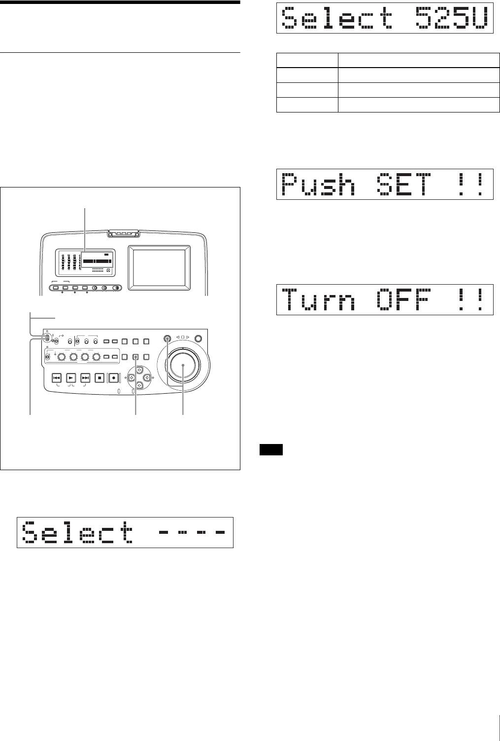
Setting procedure
Use the following procedure to set the line mode.
1
Power the unit on.
“Select ----” appears in the time data display.
2
With the SHUTTLE button held down, rotate the jog
dial.
When you rotate the jog dial in the forward direction,
the “----” part of the display changes in the sequence
525U > 525J > 625. When you rotate it in the reverse
direction, the display changes in the sequence 625 >
525J > 525U.
3
When the desired setting appears, release the
SHUTTLE button.
“Push SET !!” appears.
To redo the selection
Repeat step 2.
4
Press the SET button.
“Turn OFF !!” appears.
5
Power the unit off, and then power it on again.
The selected line mode becomes available for use.
You can change the setting made with this procedure
by using basic menu item 013 “525/625 SYSTEM
SELECT.” See 7-2-2 “Basic Menu Operations” (page
94) for more information about how to make basic
menu settings.
Note
The line mode is not set, or is cleared, in the following
situations. Reset the line mode.
• The unit is powered off before performing step 4 in the
previous procedure.
• The “RESET ALL SETUP” command in the
maintenance menu (see page 112) is executed.
Settings affected by the line mode
The following settings are affected when the line mode is
changed.
• Alarm message language
525(J): Japanese
525(U)/625: English
• The following menu item names, setting values, or
factory default setting values
AUDIO VIDEO
INPUT SEL
WARNING KEY INHI REC INHI
INPUT CH INPUT SEL STATUS
CHARACTER
LIGHT MONITOR
HLOFFOFF ON
OFF ON
-30
dB
-12
-20
-40
-60
0
CH
- 15
DATA
OVER
-30
dB
-12
-20
-40
-60
0
CH-
26
DATA
OVER
-30
dB
-12
-20
-40
-60
0
CH-
37
DATA
OVER
-30
dB
-12
-20
-40
-60
0
CH-
48 BATT E F
DATA
OVER
VITC
HOURS MINUTES SECONDS FRAMES
COUNTER HOLDVIUB
PB EXT-LKNDF
DISC E B
ACCESS
SHUTTLE JOG
THUMB
NAIL
ESSENCE
MARK
MENU
S.SEL
SET RESET
SHIFT
TOP F REV
ALL/CH-1 CH-2 CH-3 CH-4
TC
F FWD
AUDI O
END
REC
PRESET
VARIABLE
PB
PREV NEXTPLAY STOP REC
CLIP
MENU
SYSTEM
MENU
MONITOR
SEL
METER
SEL
HOLD
COUNTER
SEL
SUB
CLIP
MARK1
MARK2
IN OUT
KEY INHI
ON
OFF
NETWORK
LOCAL
REMOTE
F-RUN
R-RUN
PRESET
REGEN
INT
EXT
RP188
L/ST/R
VITC
PROCESS
CONTROL
2,354
1
AC power switch (rear panel) a)
Time data display
a) If you are using DC power or a battery pack, connect the DC power
or mount the battery pack on the battery pack shoe beforehand.
Setting Line mode
525U 525(U): NTSC (areas outside Japan)
525J 525(J): NTSC (Japan)
625 625: PAL

8 Before Using the Unit
a) Underlined values are the factory defaults.
• The following video processing parameters
Item
No.
Item name Settings a)
525 (U)/525 (J) 625
Basic menu
002 CHARACTER
H-POSITION 00 to 0A to 2A 00 to 09 to 29
003 CHARACTER
V-POSITION 00 to 2E to 38 00 to 37 to 43
Extended menu
601 VITC
POSITION
SEL-1
12H to 16H to
20H 9H to 19H to 22H
602 VITC
POSITION
SEL-2
12H to 18H to
20H 9H to 21H to 22H
628 DF MODE Item No item
652 UMID SDI
VANC LINE 12 H to 17 H to
19 H 9 H to 17 H to
18 H
660 ESSENCE
MARK SDI
VANC LINE
12 H to 17 H to
19 H 9 H to 17 H to
18 H
703 BLANK LINE
SELECT Setting range:
ALL LINE, LINE
12 to LINE 20
(525(U))/LINE
12 to LINE 21
(525(J))
Setting range:
ALL LINE, LINE
9, 332 to LINE
22, 335, LINE 23
710 INTERNAL
VIDEO
SIGNAL
GENERATOR
BB, CB75,
CB100 BB, CB75,
CB100
713 VIDEO
SETUP
REFERENCE
Item No item
723 INPUT
VIDEO
BLANK
Setting range:
ALL LINE, LINE
12 to LINE 20
Setting range:
ALL LINE, LINE
9, 332 to LINE
22, 335
Parameter name 525 (U)/525 (J) 625
Setup level Item No item
Black level No item Item

9
1-1 Features
Chapter1
Overview
1-1Features
The PDW-R1 is a convenient, compact, and lightweight
optical disc recorder. It allows you to record to optical
discs, play back optical discs, and record audio and video
data files transferred over the S400 (i.LINK 1)) connector
and (network) connector. It is ideal for field
applications and for desktop viewing by journalists,
producers, and other production staff.
1) i.LINK is a trademark of Sony Corporation.
The features of the PDW-R1 include the following.
MPEG IMX/DVCAM recording
The PDW-R1 offers the capability to record and play back
both MPEG IMX 1) and DVCAM 1) streams. Users have
the flexibility to select from these formats according to
their picture-quality needs, or to match their editing-
format requirements.
1) MPEG IMX and DVCAM are trademarks of Sony Corporation.
Proxy AV data
Proxy AV data is a low-resolution, MPEG-4 based version
of a full-resolution MPEG IMX/DVCAM stream (a video
bandwidth of 1.5 Mbps and an audio bandwidth of 64 kbps
per channel). Whenever a recording is made, the unit
automatically generates proxy AV data from the full-
resolution data and records it on the Professional Disc.
Proxy AV data is much smaller in size than the full-
resolution IMX or DVCAM data. It can be transferred
quickly over computer networks, easily edited in the field
with laptop computers, and readily used in a wide variety
of applications, such as content management on small-
scale servers.
Thumbnail search operation
Simply press the THUMBNAIL button and the PDW-R1
instantly displays thumbnails on the video panel or a
connected monitor. You can easily cue up the desired
scene by guiding the cursor to the corresponding
thumbnail and confirming your selection with the SET
button.
Scene selection
You can create and play back clip lists of selected clips
from the disc, arranged in any order.
One disc can store up to 99 clip lists.
Clip lists make it simple to perform offline editing in the
field for later use with full-scale nonlinear editing systems
(XPRI 1), etc.).
1) XPRI is a trademark of Sony Corporation.
Quick picture search by jog and shuttle
dials
The PDW-R1 has jog and shuttle dials as a conventional
VTR to search picture in a clip. The jog dial is for frame-
by-frame search at –1 to +1 times normal speed and the
shuttle dial is for high-speed search at ±20 times normal
speed.
IT-friendly system
In the PDW-R1, clips are recorded as video and audio data
files 1). This file-based recording system also allows
material to be viewed directly on a computer linked to the
unit via an i.LINK (file access mode, called FAM below)
connection—in the same way that a computer reads data
files on an external drive. The interfaces include the
S400 (i.LINK) connector, supporting AV/C (Audio/
Video Control) and i.LINK (FAM) protocols, and
(network) connector. The (network) connector
supports MXF (Material eXchange Format) file transfer
capability to exchange contents with other equipment
supporting MXF.

Chapter 1 Overview
10 1-1 Features
1) A clip is created every time recording is stopped.
•Video and audio data are always recorded in empty sections of the disc.
Recording begins instantly, even after playback, without overwriting
existing video on the disc.
•Recording is done in clip units, which makes it simple to delete a clip
immediately after shooting if it is judged to be unneeded.
•During playback, thumbnail lists make it easy to identify clips. The
random access nature of the media allows the NEXT and PREV buttons
to jump instantly to clip start frames, making it easy to check the video
and audio in the clips.
•i.LINK (FAM) or network connections make it possible to transfer clip
files at high speed between this unit and remote computers.
Flexible metadata recording
XDCAM 1) can record various types of metadata together
with video and audio data, such as the date and time of
shooting, the cameraman, the recording method, and
comments about the material. This metadata can be used in
applications such as the following.
• The supplied PDZ-1 Proxy Browsing Software can be
used to add titles, comments, and other text data to discs
and clips.
• Computer-readable text files can be recorded on the
Professional Disc, to allow systematic content
management.
• The ability to search metadata for the required audio and
video scenes brings greater efficiency to various stages
of the video production process (editing, archiving, etc.).
1) XDCAM is a trademark of Sony Corporation.
Supports a variety of interfaces
The PDW-R1 supports a variety of interfaces and is
suitable for use with various nonlinear editing systems.
Analog interfaces
Video: The unit can input and output a composite analog
video signal.
Audio: The unit has two audio channels. When in 4-
channel mode, you can input two channels of audio
either as channels 1 and 2 or as channels 3 and 4. The
two audio channels can be output also either as
channels 1 and 2 or as channels 3 and 4.
Digital interfaces
SDI (Serial Digital Interface)/AES/EBU: This allows
the unit to input and output D1 (component) format
digital video and audio signals and also AES/EBU-
format digital audio signals.
Equipped with i.LINK connector
The i.LINK connector of this unit supports the following
two functions.
Input and output of DV streams (AV/C mode)
• DV streams can be output from this unit and recorded on
standard DV equipment.
• During MPEG IMX playback, the playback signals can
be converted and output as DV streams, allowing you to
connect DV-compatible nonlinear editors.
• The output from external DV devices (VTRs, nonlinear
editors, etc.) can be input to this unit and recorded on
Professional Discs.
Computer access to files (file access mode)
Use of application software which supports the XDCAM
series 1) enables random access to video, audio, and
metadata files on Professional Discs, with the ability to
display file lists and perform file-based reads and
overwrites.
Files can be transferred at high speed, and thumbnail lists
of disc contents can be viewed on computer screens.
1) Such software includes the supplied PDZ-1 Proxy Browsing Software and
the XPRI series.
Equipped with network connector
This network connector of unit can be connected to
computers and networks to enable high-speed file transfers
and display of lists of the video, audio, and metadata files
stored on Professional Discs. Workflows can be improved
by the ability to use FTP commands to transfer files to
remote locations.
Color LCD built-in
With the built-in 3.5-inch type color LCD screen, you can
display contents on the disc without an external monitor.
Compact size, lightweight and battery-
powered operation
The PDW-R1 is designed small and light enough to carry
out to the field and it is operable with battery to work
speedily in the field.
Supporting SNMP for service and
maintenance
The PDW-R1 is compatible with Sony remote
maintenance and monitoring software—an SNMP-
compliant application that can monitor and log the
hardware’s status in real time via a TCP/IP network. If a
malfunction is detected, this system can immediately
identify the problem, allowing you to take corrective
action.
11
2-1 Configuration
Chapter2
Names and Functions of
Parts
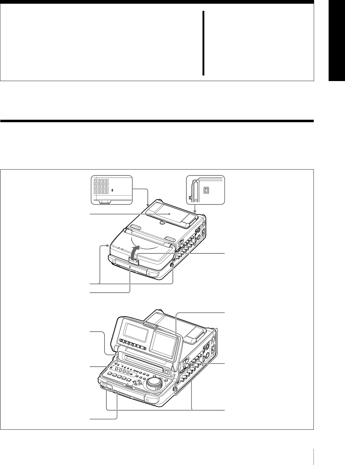
2-1 Configuration
Operation of the PDW-R1 uses the parts shown in the
following figure.
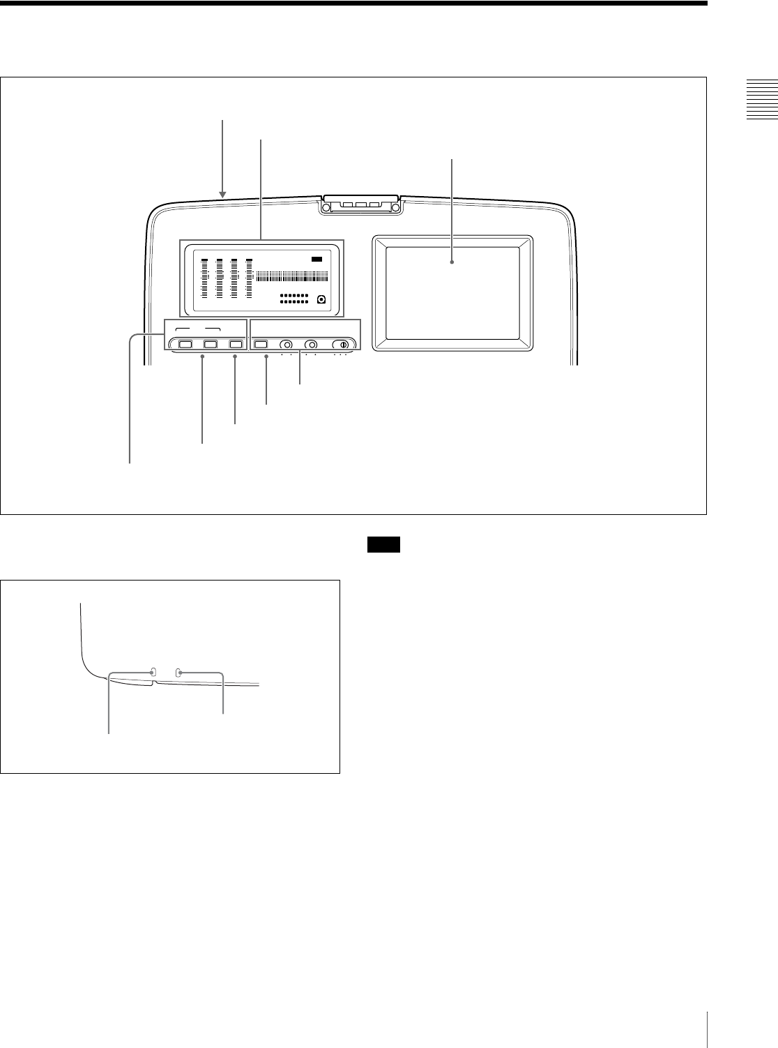
SDI
SDI
Press here to raise the cover.
Security slot
You can fit a commercially available
security cable into this slot. a)
AC power switch (rear panel)
Press " to power on; press a to
power off.
Battery pack shoe (covered)
(see page 33)
Connectors (see page 21)
Disc slot and EJECT button
(see page 38)
Control panel (see page 12)
LCD panel (see page 17)
Shoulder belt posts
(see page 134)
a) For information about how to use your
security cable, refer to the instructions
provided with the security cable.
Built-in speaker (monaural)
Carrying handle
Use this to carry the unit.
Cable clamp (see page 22)
Chapter 2 Names and Functions of Parts
12 2-2 Control Panel
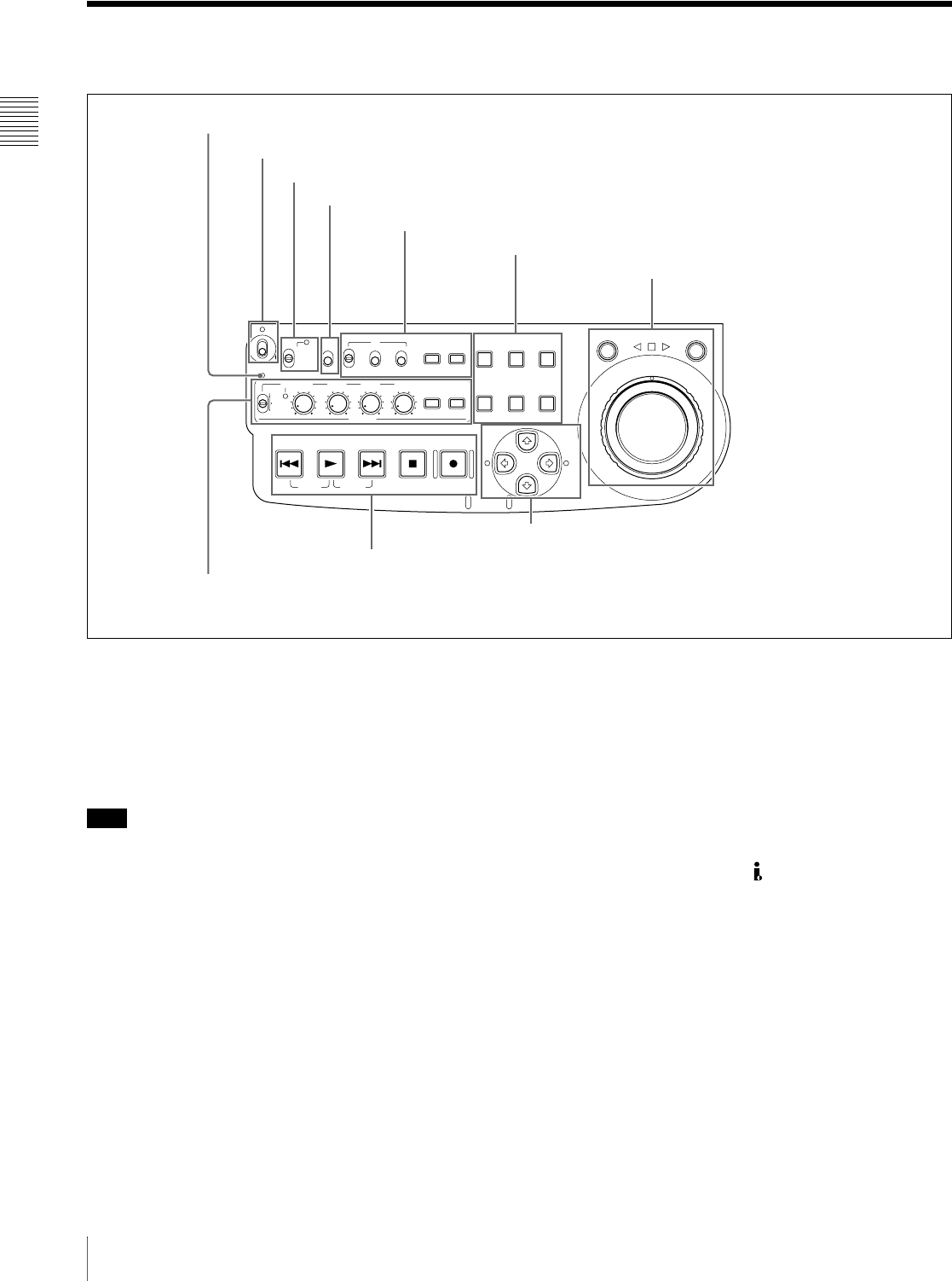
2-2 Control Panel
aACCESS indicator
This lights when the disc is accessed and when a file is
opened by a FAM or FTP connections (see page 72).
If the on/standby switch is set to the 1 position while this
indicator is lit, access to the disc is completed before the
unit switches to the standby state.
Note
While the ACCESS indicator is lit, do not turn off the AC
power switch, disconnect the power cord, or remove the
battery. This could lead to a loss of data from the disc.
bOn/standby ("/1) switch and indicator
When the AC power switch on the rear panel is in the "
position, or a battery is loaded, this switches the PDW-R1
between the operating (") and standby (1) states. When
the switch is moved to the " position, the indicator lights.
When the switch is moved to the 1 position, the indicator
goes off.
When operating the PDW-R1 from an AC power supply,
normally leave the AC power switch in the " position, and
switch the PDW-R1 between the operating and standby
states using the on/standby switch.
cRemote control switch and NETWORK access
indicator
Different positions of the switch allow different operations
as follows.
NETWORK: Enables access to the network. The
indicator lights when an external network device is
being accessed. In this state, operation from the
control panel is not possible.
LOCAL: Enables operation from the control panel.
REMOTE: Enables remote control of the PDW-R1 from
a device connected to the S400 (i.LINK) connector
or REMOTE connector on the side panel.
Use extended menu item 214 “REMOTE
INTERFACE” to select which of the connectors is
used.
See 7-3-2 “Extended Menu Operations” (page 108)
for more information about how to make extended
menu settings.
dKEY INHI (key inhibit) switch
Setting this switch to ON lights the KEY INHI indicator
and disables the switches and buttons that are set to “dis”
with extended menu item 118 “KEY INHIBIT.”
ACCESS
SHUTTLE JOG
THUMB
NAIL
ESSENCE
MARK
MENU
S.SEL
SET RESET
SHIFT
TOP F REV
ALL/CH-1 CH-2 CH-3 CH-4
TC
F FWD
AUDIO
END
REC
PRESET
VARIABLE
PB
PREV NEXTPLAY STOP REC
CLIP
MENU
SYSTEM
MENU
MONITOR
SEL
METER
SEL
HOLD
COUNTER
SEL
SUB
CLIP
MARK1
MARK2
IN OUT
KEY INHI
ON
OFF
NETWORK
LOCAL
REMOTE
F-RUN
R-RUN
PRESET
REGEN
INT
EXT
RP188
L/ST/R
1 ACCESS indicator
2 On/standby switch and indicator
3 Remote control switch and NETWORK access indicator
3Jog/shuttle control block (see page 14)
2Operating mode selection/menu setting section (see page 13)
1 Time data settings section (see page 13)
4 KEY INHI switch
6 Arrow buttons (see page 16)
5 Recording and playback control section (see page 16)
4 Audio settings section (see page 15)
Chapter 2 Names and Functions of Parts
13
2-2 Control Panel
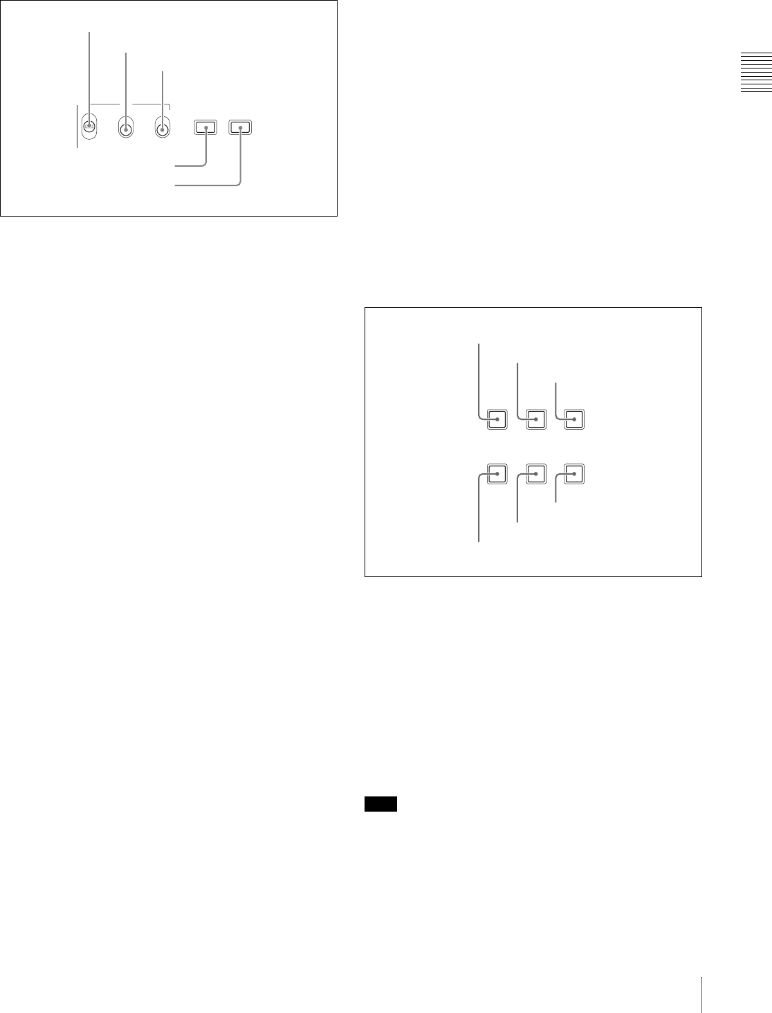
1 Time data settings section
aINT/EXT/RP188 (internal/external/RP188
selector) switch
Before recording time code, select the type of time code
with this switch.
INT: Use time code generated internally by this unit.
EXT: Use time code input from an external source.
RP188: Use SMPTE RP188 LTC in an SDI signal.
bPRESET/REGEN (regeneration) switch
This switch selects whether to preset a new time code
value or follow already recorded time code.
PRESET: Record time code starting with a preset initial
value.
REGEN: Record time code continuous with existing time
code on the disc. Regardless of the setting of the F-
RUN/R-RUN switch, the unit operates in R-RUN
mode.
cF-RUN/R-RUN (free run/recording run) switch
This switch selects the operating mode of the internal time
code generator.
F-RUN: Time code advances regardless of the operating
state of the unit. Use this setting to align the time code
with real time or to synchronize the time code with
external time code.
R-RUN: Time code advances only during recording. Use
this setting to obtain consecutive time code on the disc.
For details, see 4-1-2 “Recording Time Code and User Bit
Values” (page 44).
dCOUNTER SEL button
This cycles the data displayed in the time data display
through the sequence TC, UB, and COUNTER.
TC: The playback time code read by the internal time code
reader, or the time code generated by the internal time
code generator.
Make the TC or VITC selection in extended menu item
629 “TC SELECT.”
UB: The user bits inserted in the playback time code, or
user bits generated by the internal time code generator.
Make the UB or VIUB selection in extended menu
item 629 “TC SELECT.”
COUNTER: The elapsed recording/playback time (hours,
minutes, seconds, frames). This can be reset by
pressing the RESET button (see page 14).
The corresponding indicator above the time data display
lights according to the setting.
You can also synchronize timecode with the time of the
internal clock. For details, see “To set time code to the
time of the internal clock” (page 45).
eHOLD button
Press this button to stop the time code generator.
Also, when setting the time code or user bits to be
recorded, press this button first, to hold the values.
2 Operating mode selection/menu setting
section
aSUBCLIP button
To play back following a clip list, press this button, turning
it on (see page 54). This is also effective for jog and shuttle
operations.
To play clips in the order they are recorded, press this
button again, turning it off.
The CLIP menu (see page 68) appears in the time data
display, in the video panel, and on an external monitor
when you press this button with the SHIFT button held
down. Press the MENU button to escape from the CLIP
menu.
Note
If no clip list is registered, this button does not light when
pressed. The operation is invalid.
bTHUMBNAIL button
To carry out a thumbnail search or create a clip list, press
this button turning it on. Thumbnail images representing
TC
HOLD
COUNTER
SEL
F-RUN
R-RUN
PRESET
REGEN
INT
EXT
RP188
1 INT/EXT/RP188 switch
2 PRESET/REGEN switch
3 F-RUN/R-RUNswitch
4 COUNTER SEL button
5 HOLD button
THUMB
NAIL
ESSENCE
MARK
MENU
S.SEL
SET RESET
SHIFT
CLIP
MENU
SYSTEM
MENU
SUB
CLIP
1 SUBCLIP button
2 THUMBNAIL button
3 SHIFT button
4 MENU button
5 SET button
6 RESET button

Chapter 2 Names and Functions of Parts
14 2-2 Control Panel
each clip or sub-clip appear. Press once more to turn the
button off, and return to a whole-screen display.
To display the thumbnails of essence mark frames (frames
with an essence mark attached), hold down the SHIFT
button, and press this button. The essence mark selection
menu appears. Select the desired type of essence mark, and
the corresponding essence mark frames appear in
thumbnails. Press once more, turning the button off, to
return to a whole-screen display.
cSHIFT button
Use to switch the functions of various buttons.
dMENU button
Use for setup menu and system menu operations. Pressing
this button displays the setting of a setup menu item in the
time data display. The same information is also
superimposed on the displays of the video panel and a
monitor connected to this unit (see page 94). Press once
more to return to the original display. The system menu
(see page 117) appears in the time data display, in the
video panel, and on an external monitor, when you press
this button with the SHIFT button held down. Press this
button again to escape from the system menu.
eSET button
Use for setup menu settings (see page 94), scene selection
(thumbnail search) settings, and so on.
The scene selection window or a menu for sub clip
operations appears when you press this button with the
SHIFT button held down with either of the following
displayed. The window or menu appears in the video
panel, and on an external monitor.
When a thumbnail screen is displayed: The scene
selection window (see page 62) appears.
When a sub clip thumbnail is displayed: A sub clip
operation menu (see page 64) appears.
fRESET button
Press to reset the counter. This is also used to cancel or
abandon setup menu settings and scene selection
(thumbnail search).
3 Jog/shuttle control block
For details of playback operations with these buttons and
dials, see 4-2-2 “Playback Operation” on page 51.
aSHUTTLE button
To play back in shuttle mode using the shuttle dial, press
this button, turning it on.
This button switches to shuttle mode whenever it is
pressed, even during recording. If you do not want
recording to stop with this button, set extended menu item
145 “MODE KEY ENABLE DURING RECORDING” to
“stop.”
Pressing the JOG button or turning the jog dial switches to
jog mode.
bJog/shuttle transport indicators
These show the playback direction in jog or shuttle speed
mode.
b (green): Lights during playback in the reverse direction.
B (green): Lights during playback in the forward direction.
x (red): Lights during still image display.
cJOG button
To play back in jog mode using the jog dial, press this
button, turning it on.
This button switches to jog mode whenever it is pressed,
even during recording. If you do not want recording to stop
wih this button, set extended menu item 145 “MODE KEY
ENABLE DURING RECORDING” to “stop.”
Pressing the SHUTTLE button or turning the shuttle dial
switches to shuttle mode.
dJog dial
Turn this for playback in jog mode. Turn clockwise for
forward direction playback, and counterclockwise for
reverse direction playback. In jog mode, the playback
SHUTTLE JOG
1 SHUTTLE button
2 Jog/shuttle transport
indicators
3 JOG button
4 Jog dial
5 Shuttle dial
Chapter 2 Names and Functions of Parts
15
2-2 Control Panel
speed varies in the range ±1 times normal speed, according
to the rotation rate of the jog dial. There are no detents.
Normally, you press the JOG button before turning the jog
dial, but it is also possible to make a setting to enable jog
mode directly by turning the dial (set extended menu item
101 “SELECTION FOR SEARCH DIAL ENABLE” to
“dial”).
eShuttle dial
Turn this for playback in shuttle mode. Turn clockwise for
forward direction playback, and counterclockwise for
reverse direction playback. In shuttle mode, the playback
speed varies in the range ±20 times normal speed (using
MPEG IMX/DVCAM), according to the angular position
of the shuttle dial. The shuttle dial has a detent at the center
position, for still image playback.
Normally, you press the SHUTTLE button before turning
the shuttle dial, but it is also possible to make a setting to
enable shuttle mode directly by turning the dial (set
extended menu item 101 “SELECTION FOR SEARCH
DIAL ENABLE” to “dial”).
Note
When extended menu item 101 “SELECTION FOR
SEARCH DIAL ENABLE” is set to “dial,” after using the
shuttle dial, return it to the center position. If the shuttle
dial is not in the center position, it is possible occasionally
for vibration from other operations to activate the dial, and
start playback in shuttle mode.
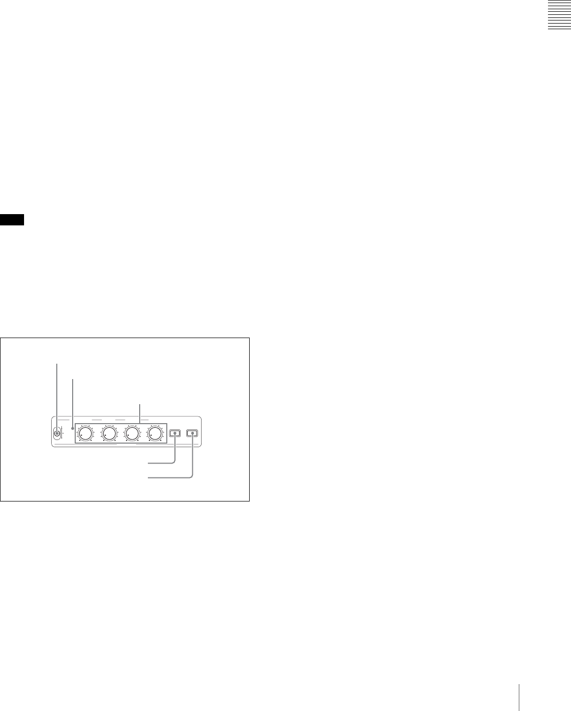
4 Audio settings section
aVARIABLE (audio level adjustment selector)
switch
This selects which of the input audio and playback audio
has the level adjusted by the ALL/CH-1, and CH-2 to CH-
4 adjustment knobs.
REC: Adjust the input audio levels. The playback audio
levels are fixed at their preset values.
PRESET: Do not adjust the audio levels.
PB: Adjust the playback audio levels. The input audio
levels are fixed at their preset values.
bALL/CH-1, CH-2 to CH-4 (audio level) adjustment
knobs
Depending on the setting of the VARIABLE switch, these
adjust the input audio or playback audio levels of channels
1 to 4.
By the setting of extended menu item 131 “AUDIO
VOLUME,” you can enable the ALL/CH-1 knob to
simultaneously adjust all eight channels. When this
simultaneous adjustment is enabled the ALL indicator
lights.
cAUDIO METER SEL (selection) button
When using MPEG IMX format in eight-channel mode,
select whether the audio level meters should display
channels 1 to 4 or channels 5 to 8.
Pressing this button toggles the selection, and the audio
level meter channel display also changes.
The factory default is for channels 1 to 4 to be selected.
dAUDIO MONITOR SEL (selection) button
This button selects two channels from among the up to
eight audio signal channels. You can monitor the audio of
the selected channels (the left and right channels in the
case of stereo output) with the PHONES jack on the front
panel and the built-in speaker.
Pressing this button cycles through the following five
channel combinations.
•tr1/2: Channels 1 (left) and 2 (right)
•tr3/4: Channels 3 (left) and 4 (right)
•tr5/6: Channels 5 (left) and 6 (right)
•tr7/8: Channels 7 (left) and 8 (right)
•MENU: Audio channels selected with extended menu
item 837 and 838 “AUDIO MONITOR CHANNEL
ARRANGE”
The factory default is for channels 1 (left) and 2 (right) to
be selected.
You can select whether to monitor both of the selected
channels or only one, by pressing this button with the
SHIFT button held down. Each press selects stereo, right,
or left.
ST: Stereo audio is output from the PHONES jack.
Monaural audio, the left and right channels mixed, is
output from the built-in speaker.
R: The right channel audio is output from the PHONES
jack and the built-in speaker.
L: The left channel audio is output from the PHONES jack
and the built-in speaker.
ALL/CH-1 CH-2 CH-3 CH-4
AUDIO
REC
PRESET
VARIABLE
PB
MONITOR
SEL
L/ST/R
METER
SEL
1 VARIABLE switch
ALL indicator
2 ALL/CH1, CH-2 to CH4
adjustment knobs
3 AUDIO METER SEL button
4 AUDIO MONITOR SEL button
Chapter 2 Names and Functions of Parts
16 2-2 Control Panel
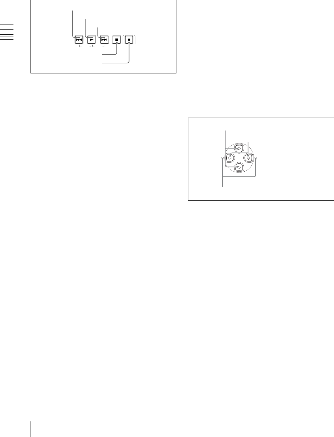
5 Recording and playback control section
aPREV (previous) button
Press this button, turning it on, to show the first frame of
the current clip. While the first frame of a clip is shown,
pressing this button jumps to the beginning of the previous
clip.
This button is also used together with other buttons for the
following operations.
Reverse direction high-speed search: Hold down the
PLAY button, and press this button. A high-speed
search in the reverse direction is carried out.
Displaying the first frame of the first clip: Hold down
the SHIFT button, and press this button.
bPLAY (playback) button
To start playback, press this button, turning it on.
This button stops recording whenever it is pressed, even
during recording. If you do not want recording to stop with
this button, set extended menu item 145 “MODE KEY
ENABLE DURING RECORDING” to “stop.”
cNEXT button
Press this button, turning it on, to jump to the next clip, and
show the first frame.
This button is also used together with other buttons for the
following operations.
Forward direction high-speed search: Hold down the
PLAY button, and press this button. A high-speed
search in the forward direction is carried out.
Displaying the last frame of the last clip: Hold down the
SHIFT button, and press this button.
dSTOP button
To stop recording or playback, press this button, turning it
on. The frame at the stop point appears.
The unit enters standby off mode when you press this
button with the SHIFT button held down. It returns from
standby off mode to the original state when you press this
button again with the SHIFT button held down. (The lit or
unlit status of the STOP button does not change.)
This unit can automatically enter standby off mode
whenever a specified time elapses in disc stop mode. For
details, see the description of extended menu item 501
“STILL TIMER” (page 101).
eREC (record) button
To start recording, hold down this button, and press the
PLAY button. The recording takes place on an unrecorded
part of the disc.
To stop recording, press the STOP button.
This creates a clip of the recorded portion.
6 Arrow buttons
The four arrow buttons are also used as the MARK1
button, MARK2 button, IN button, and OUT button. The
correspondence with the buttons is as follows.
F button: MARK1 button
f button: MARK2 button
G button: IN button
g button: OUT button
You can use these buttons for thumbnail selection, menu
setting operations, setting IN/OUT points, and so on.
aF/MARK1 button and f/MARK2 button
When the THUMBNAIL button (see page 13) is lit, you
can use these for thumbnail selection.
During recording and playback, the F/MARK1 and f/
MARK2 buttons can be pressed with the SET button held
down to record a shot mark 1 or shot mark 2 as an essence
mark.
To delete or change essence marks, use the supplied PDZ-
1 Proxy Browsing Software.
bG/IN button and g/OUT button
When the THUMBNAIL button (see page 13) is lit, you
can use these for thumbnail selection.
An In or Out point is set when you press the SET button
with the G/IN or g/OUT button held down. The In or Out
point setting is deleted when you press the RESET button
with the G/IN or g/OUT button held down.
cIN indicator and OUT indicator
IN indicator: When an IN point is set, this lights.
If an attempt is made to set the IN point after a
recorded OUT point, this flashes.
OUT indicator: When an OUT point is set, this lights.
If an attempt is made to set the OUT point before a
recorded IN point, this flashes.
TOP F REV F FWD END
PREV NEXTPLAY STOP REC
1 PREV button
2 PLAY button
3 NEXT button
4 STOP button
5 REC button
MARK1
MARK2
IN OUT
1 F/MARK1 button and f/MARK2 button
2 G/IN button and g/OUT
button
3 IN indicator and OUT indicator
Chapter 2 Names and Functions of Parts
17
2-3 LCD Panel
2-3 LCD Panel
aIndicators on the back of the LCD panel
There are two indicators, as follows.
OPERATION indicator: Lights when the on/standby
switch on the control panel is in the on (") position.
ACCESS indicator: Lights when the disc is being
accessed. If the on/standby switch is set to the 1
position while this indicator is lit, access to the disc is
completed before the unit switches to the standby
state.
Note
While the ACCESS indicator is lit, do not turn off the AC
power switch, disconnect the power cord, or remove the
battery. This could lead to a loss of data from the disc.
bVideo panel (color)
In recording, playback and editing operations, this shows
recording and playback video, thumbnails, and other
images. A status screen appears here when you press the
STATUS button (see page 19).
cWARNING indicator
This lights when condensation within the PDW-R1, a laser
diode fault, or another hardware error is detected. It goes
off when the error state is cleared. When this indicator is
lit, the time data display and video panel show an error
message.
For details, see 8-3 “Error Messages” (page 121) and 8-
4 “Alarms” (page 122).
dKEY INHI (key inhibit) indicator
This lights when the KEY INHI switch is set to on, with
either “MON./INPUT SEL” or “CONTROL PANEL” set
to “dis” in extended menu item 118 “KEY INHIBIT.”
AUDIO VIDEO
INPUT SEL
WARNING KEY INHI REC INHI
INPUT CH INPUT SEL STATUS CHARACTER LIGHT MONITOR
HLOFFOFF ON
OFF ON
-30
dB
-12
-20
-40
-60
0
CH
- 15
DATA
OVER
-30
dB
-12
-20
-40
-60
0
CH-
26
DATA
OVER
-30
dB
-12
-20
-40
-60
0
CH-
37
DATA
OVER
-30
dB
-12
-20
-40
-60
0
CH-
48 BATT E F
DATA
OVER
VITC
HOURS MINUTES SECONDS FRAMES
COUNTER HOLDVIUB
PB EXT-LKNDF
DISC E B
VITC
PROCESS
CONTROL
1 Indicators on the back of the LCD panel
3 WARNING indicator
3 Display settings section (see page 19)
1 Status display (see page 18)
2 Video panel (color)
4 KEY INHI indicator
5 REC INHI indicator
2 Audio and video settings section (see page 19)
OPERATION ACCESS
ACCESS indicator
OPERATION indicator
Chapter 2 Names and Functions of Parts
18 2-3 LCD Panel
eREC INHI (recording inhibit) indicator
This lights in the following cases.
• When a disc with recording inhibited is loaded.
• When extended menu item 310 “REC INHIBIT” is set to
“on.”
• The format of the recorded part of the disc does not
match the settings of the PDW-R1 (number of recorded
channels, TV system (525/625 selection), and recording
format (DVCAM/IMX50/IMX40/IMX30 selection)).
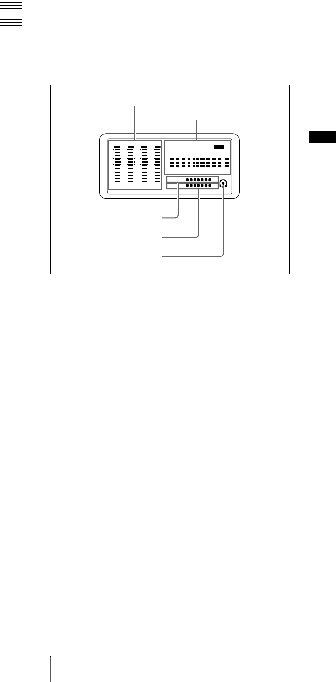
1 Status display
aAudio level meters
Depending on the setting of the AUDIO METER SEL
button (see page 15), these show the audio recording levels
(during recording) or audio playback levels (during
playback) of channels 1 to 4 or channels 5 to 8. If an audio
level exceeds 0 dB, the OVER indicator lights.
The DATA indicator lights when non-audio signals are
played back.
By means of a maintenance menu setting, you can display
a reference level indicator (“-”) to the right of each meter
when recording.
For details of the maintenace menu, see 7-4 “Maintenance
Menu” on page 112.
bTime data display
Normally, this shows the disc playback time, time code, or
user bit information, as selected by the COUNTER SEL
button (see page 13) and extended menu item 629 “TC
SELECT.”
It is also used for error messages, setup menus, and other
displays.
The following indicators are located above the time data
display.
COUNTER indicator: This lights when a counter value
(hours, minutes, seconds, and frames, resettable) is
displayed in the time data display.
HOLD indicator: This lights when the internal time code
generator (TCG) is stopped. Does not light when the
output of the time code reader (TCR) is being
displayed during playback and stop.
TC/VITC (time code type) indicator: This lights when
the COUNTER SEL button (see page 13) is set to TC.
The time data display shows the time code.
When extended menu item 629 “TC SELECT” is set
to “tc,” this shows “TC,” and when “vitc” is selected,
it shows “VITC.”
UB/VIUB (user bit type) indicator: This lights when the
COUNTER SEL button is set to UB. The time data
display shows the user bits.
When extended menu item 629 “TC SELECT” is set
to “tc,” this shows “UB,” and when “vitc” is selected
it shows “VIUB.”
indicator: This lights in the following cases.
• In playback mode, when VITC is being read.
(Regardless of what the time data display is
showing.)
• When VITC is being recorded, or in E-E mode 1)
when VITC is recorded due to one of the following
conditions.
- Extended menu item 619 “VITC” is set to “on.”
- There is VITC in the selected video input signal,
and that line has been set to “thru” with extended
menu item 723 “INPUT VIDEO BLANK.”
PB (playback) indicator: This lights when the output of
the time code reader (TCR) is being displayed.
NDF (non-drop-frame) indicator: This lights in E-E
mode when extended menu item 628 is set to “ndf,”
and during playback when the clip on the disc has non-
drop-frame time code.
EXT-LK (external synchronization) indicator: This
lights when the internal time code generator is locked
to an external signal input to the TC IN connector.
1) E-E mode: Abbreviation of Electric to Electric mode. The mode in which
input video and audio signals are output after passing only through the
electrical circuits.
cDISC remaining capacity indicator
This shows the amount of free capacity on the current disc,
as follows.
xxxxxxx (7 segments lit): All capacity is available.
As clips are recorded, the number of lit LED segments
decreases.
“DISC” flashing: The disc is almost full.
“DISC” and “E” flashing: The disc is full (it must be
replaced).
dBATT (battery) status display
This shows the amount of charge left in the battery, as
follows.
xxxxxxx (7 segments lit): Adequately charged. As
the battery discharges, the number of lit LED segments
decreases.
“BATT” flashing: Almost exhausted. Operation of the
PDW-R1 continues.
-30
dB
-12
-20
-40
-60
0
CH
- 15
DATA
OVER
-30
dB
-12
-20
-40
-60
0
CH-
26
DATA
OVER
-30
dB
-12
-20
-40
-60
0
CH-
37
DATA
OVER
-30
dB
-12
-20
-40
-60
0
CH-
48 BATT E F
DATA
OVER
VITC
HOURS MINUTES SECONDS FRAMES
COUNTER HOLDVIUB
PB EXT-LKNDF
DISC E B
VITC
1 Audio level meters
5 Disc loaded mark
2 Time data display
4 BATT display
3DISC remaining
capacity indicator
VITC
Chapter 2 Names and Functions of Parts
19
2-3 LCD Panel
“BATT” and “E” flashing: Exhausted (charging
required). Operation of the PDW-R1 stops.
eDisc loaded mark
This lights while a disc is loaded in the PDW-R1. It flashes
as the disc is inserted, and while it is being ejected.
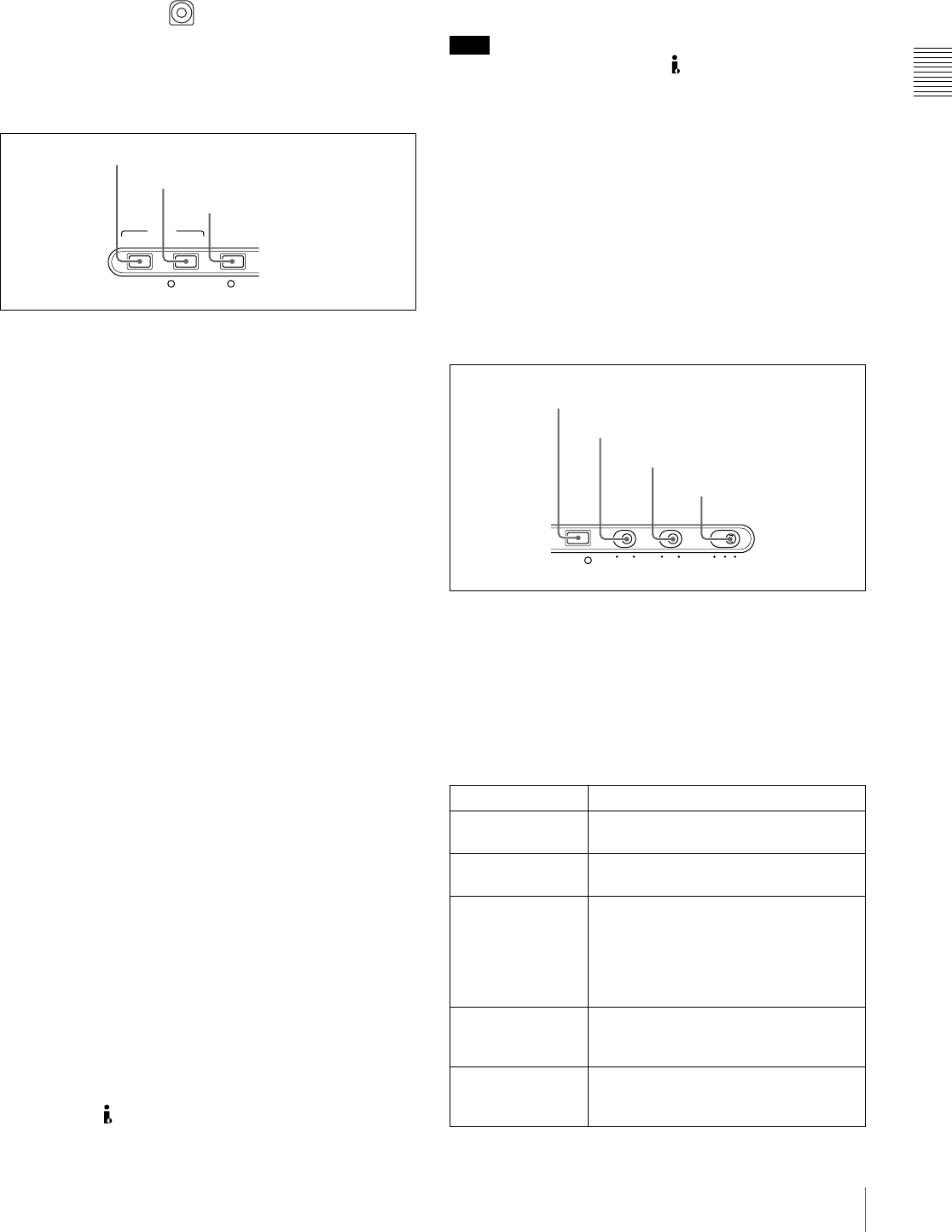
2 Audio and video settings section
aAUDIO INPUT CH (channel) button
This selects the channel to which the audio input signal
selection applies.
Each press of this button selects the next audio input
channel, in the following order.
CH1 t CH2 t CH3 t CH4
The selected channel appears in the time data display and
video panel.
You can use the AUDIO INPUT SEL button to select the
audio input signal for the selected channel.
When audio is in eight-channel mode
On channels 5 to 8, you can input only the audio signals
embedded in an SDI signal.
bAUDIO INPUT SEL (selection) button
This selects the input signal to the channel selected with
the AUDIO INPUT CH button described above.
Each press of this button selects the next audio input
signal, and the audio input indications in the time data
display and video panel change to reflect this.
ANALOG: Analog audio signal input to the AUDIO IN
connector
SDI: SDI audio signal input to the SDI IN connector
AES/EBU: AES/EBU format digital audio signal input to
the DIGITAL AUDIO (AES/EBU) IN connector
SG: Audio test signal generated by the internal signal
generator
cVIDEO INPUT SEL (selection) button
Pressing this button cycles through the following
selections of the video input signal.
• SDI video signal input to the SDI IN connector
• Composite video signal input to the VIDEO IN
connector
• Test video signal from the internal signal generator
• i.LINK-compliant DVCAM format digital signal
(i.LINK input comprising both video and audio signals)
input to the S400 (i.LINK) connector
Signals are selected in the following order. The video input
indication in the video panel changes to reflect this.
SDI t COMPOSITE t SG t i.LINK
Note
Input signals (AV/C) from the S400 (i.LINK) connector
cannot be recorded when the basic menu item 031
“RECORDING FORMAT” is set to “IMX 50,” “IMX40,”
or “IMX 30.” E-E video display and audio output are also
not possible.
Select a signal other than “i.LINK” to record IMX format
video signals. When i.LINK input signals are selected, set
basic menu item 031“RECORDING FORMAT” to
“DVCAM.”
See 7-2-2 “Basic Menu Operations” (page 94) for more
information about how to make basic menu settings.
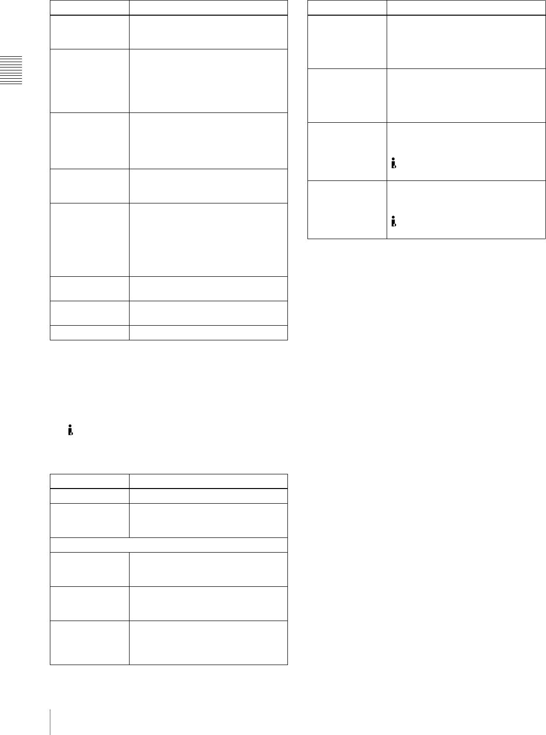
3 Display settings section
aSTATUS button
Displays information about the current settings of this unit
in the video panel.
The displayed information changes in the following order
with each press of the button.
Page 1 t Page 2 t Display off
Items displayed on page 1
AUDIO VIDEO
INPUT SEL
WARNING KEY INHI RE
INPUT CH INPUT SEL
1 AUDIO INPUT CH button
3 VIDEO INPUT SEL button
2 AUDIO INPUT SEL button
Item Description
525, 625 Line mode selected with basic menu
item 013
IMX50, IMX40,
IMX30, DVCAM Video recording format selected with
basic menu item 031
8ch, 4ch Number of audio recording channels
(When the format is IMX50/40/30, this
is the number of channels specified by
maintenance menu item “AUDIO
CONFIG” - “DATA LENGTH.” When the
format is DVCAM, this is always 4ch.)
VIN The video input signal selected with the
VIDEO INPUT SEL button (setting
values: SDI, COMPST, SG, i.LINK)
AINn (n: channel
number 1 to 4) The audio input signal selected with the
AUDIO INPUT SEL button (setting
values: SDI, AES/EBU, SG, ANALOG)
REC INHI
STATUS CHARACTER LIGHT MONITOR
HLOFFOFF ON
OFF ON
PROCESS
CONTROL
1 STATUS button
3 LIGHT switch
2 CHARACTER switch
4 MONITOR switch
Chapter 2 Names and Functions of Parts
20 2-3 LCD Panel
a) This appears when a disc is loaded, and the format of a clip recorded on
the disc is different from the format specified by basic menu item 031 or
the setting of the “AUDIO CONFIG” - “DATA LENGTH” item in the
maintenance menu.
b) 9PIN: When extended menu item 214 is set to “9PIN”
i.LINK: When extended menu item 214 is set to “i.LINK” and menu item
215 is set to “AV/C”
— — —: When extended menu item 214 is set to “i.LINK” and menu item
215 is set to “FAM” (remote control from a device connected to the
S400 (i.LINK) connector is not possible when this combination of
settings is in force)
Items displayed on page 2
When you press this button with the SHIFT button held
down, the process control screen appears in the video
panel. You can use this screen to adjust the following
parameters.
• Video output level
• Chroma output level
• Setup/black level
• Chroma phase
• Output signal sync phase
• Output signal subcarrier phase
See “Adjusting video processing parameters” (page 49)
for more information about how to make the adjustments.
bCHARACTER switch
Selects whether or not to superimpose the time code, menu
settings, alarm messages, or other text information on the
video signals output from the side panel SDI OUT
(SUPER) and VIDEO OUT 2 (SUPER) connectors and
also on the unit’s video panel.
ON: Superimpose character information.
OFF: Do not superimpose character information.
The factory default setting is ON.
cLIGHT switch
Selects whether the status display backlight is on or off.
ON: On.
OFF: Off.
The factory default setting is ON.
dMONITOR switch
Selects whether to display video in the video panel.
H: Display with high brightness.
L: Display with low brightness.
OFF: Do not display.
The factory default setting is H.
PROC This appears when at least 1 video
processing parameter has been set to
“VAR (VARIABLE).”
DISC a) The line mode of the current clip on the
disc (setting values: 525, 625), the
video recording format (setting values:
IMX50, IMX40, IMX30, DVCAM), and
the number of audio recording
channels (setting values: 8ch, 4ch)
RMT When the remote control switch is set
to REMOTE, the control interface
selected with extended menu item 214
(setting values: 9PIN, i.LINK,
— — —) b)
PARA This appears when the parallel
recording with camcorder function is
enabled.
AC IN
DC IN ??.?V
BATT ??% (??.?V)
The type of power supplied to this unit
(AC IN: AC power, DC IN: DC power,
BATT: battery pack). The voltage (units:
V) appears when DC power is used,
and the remaining battery charge (unit:
% or V) appears when the battery pack
is used.
??MIN Free capacity remaining on disc (unit:
minutes)
??? Playback order number of clip being
played back
??h??m??s?? Duration of clip being played back
Item Description
VIDEO INPUT Same as VIN on page 1
AUDIO INPUT n
(n: channel
number 1 to 4)
Same as AINn on page 1
AUDIO OUTPUT
MONITOR L/R Audio channels selected with AUDIO
MONITOR SEL button (setting values:
tr1/2, tr3/4, tr5/6, tr7/8, MENU)
(MONITOR)
L/ST/R Monitor channel selected with SHIFT +
AUDIO MONITOR SEL button (setting
values: STEREO, R, L)
ANALOG 1/2 Audio channels (setting values: tr1/2,
tr3/4, tr5/6, tr7/8) assigned to the
AUDIO OUT 1/3, 2/4 connectors with
extended menu item 824
Item Description
AES/EBU 1/2 Audio channels (setting values: tr1/2,
tr3/4, tr5/6, tr7/8) assigned to the
DIGITAL AUDIO (AES/EBU) OUT 1/2
connectors with sub item 1 of extended
menu item 827
(AES/EBU) 3/4 Audio channels (setting values: tr1/2,
tr3/4, tr5/6, tr7/8) assigned to the
DIGITAL AUDIO (AES/EBU) OUT 3/4
connectors with sub item 2 of extended
menu item 827
SDI/DV 1/2 Audio channels (setting values: tr1/2,
tr3/4, tr5/6, tr7/8) assigned to channels
1 and 2 of the SDI OUT (SUPER) and
S400 (i.LINK) connectors with sub
item 1 of extended menu item 828
(SDI/DV) 3/4 Audio channels (setting values: tr1/2,
tr3/4, tr5/6, tr7/8) assigned to channels
3 and 4 of the SDI OUT (SUPER) and
S400 (i.LINK) connectors with sub
item 2 of extended menu item 828
Item Description
Chapter 2 Names and Functions of Parts
21
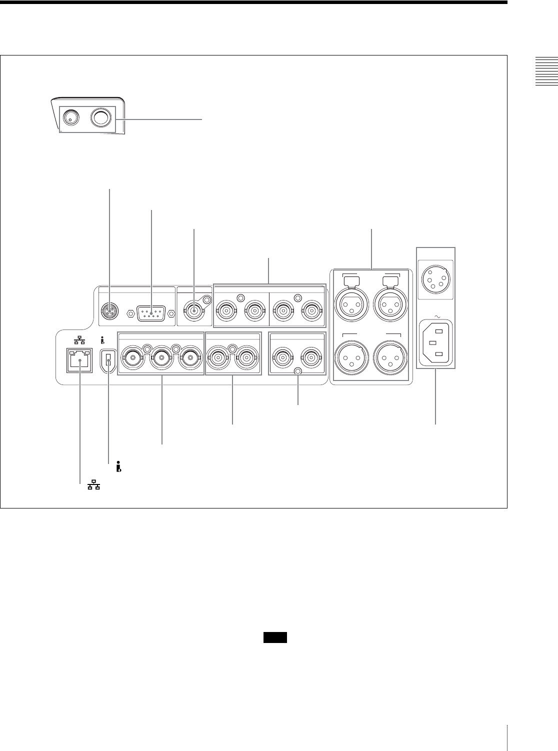
2-4 Connectors
2-4 Connectors
aPHONES jack and LEVEL knob
The jack is a standard stereo jack. Connect stereo
headphones with an impedance of 8 ohms, to monitor the
audio during playback. (Non-audio signals are muted.)
The channels monitored are selected by the AUDIO
MONITOR SEL button.
Adjust the volume with the LEVEL knob. When extended
menu item 820 “AUDIO OUTPUT CH1/CH2 SELECT”
is set to “moni,” you can also cause this to simultaneously
adjust the output volume from the AUDIO OUT 1/3 and 2/
4 connectors on the side panel. To do this, in the setup
menu, set extended menu item 114 “AUDIO MONITOR
OUTPUT LEVEL” to “var.”
When no headphones are connected, you can listen to
audio through the built-in speaker (monaural).
bDC OUT (DC power output) 12V connector (4-pin,
female)
Supplies power to the BVR-3 Remote Control Unit (not
supplied) and the RM-280 Editing Controller (not
supplied). (Max. 5 W)
Note
Do not connect to any external device except those listed
above.
PHONES
REF VIDEO INREMOTE DIGITAL AUDIO (AES/EBU)
AC IN
DC IN
12V
S400
IN
DC OUT 12V 1/2 3/4 OUT 1/2 3/4
SDI
IN OUT(SUPER)
VIDEO
IN OUT1 OUT2(SUPER)
TC
IN OUT
AUDIO OUT
1/3 2/4
1/3 2/4
AUDIO IN
1 PHONES jack and LEVEL knob
2 DC OUT 12V connector
3 REMOTE connector
4 REF VIDEO IN connector
2Analog audio signal inputs/
outputs (see page 23)
3 Analog video signal inputs/outputs (see page 23)
4 SDI signal inputs/outputs (see page 23)
5 (network) connector
6Power supply
section (see
page 24)
5Time code inputs/outputs
(see page 24)
Front
Right side
1Digital audio signal
inputs/outputs (see page
6 S400 (i.LINK) connector
Chapter 2 Names and Functions of Parts
22 2-4 Connectors
cREMOTE (remote control signal) connector (D-
sub 9-pin)
To control the PDW-R1 from a controller or VTR
supporting the RS-422A Sony 9-pin VTR protocol,
connect the device to this connector.
dREF VIDEO IN (reference video signal input)
connector (BNC type)
Input a reference video signal.
e(network) connector (RJ-45 type)
This is a 10Base-T/100Base-TX connector for network
connection.
To transfer files between an external device and the PDW-
R1, connect a network cable to this connector and the
external device.
Caution
For safety, do not connect the connector for peripheral
device wiring that might have excessive voltage to this
port. Follow the instructions in this manual when making
connections.
ATTENTION
Par mesure de sécurité, ne raccordez pas le connecteur
pour le câblage de périphériques pouvant avoir une tension
excessive à ce port. Suivez les instructions pour ce port.
ACHTUNG
Aus Sicherheitsgründen nicht mit einem Peripheriegerät-
Anschluss verbinden, der zu starke Spannung für diese
Buchse haben könnte. Folgen Sie den Anweisungen für
diese Buchse.
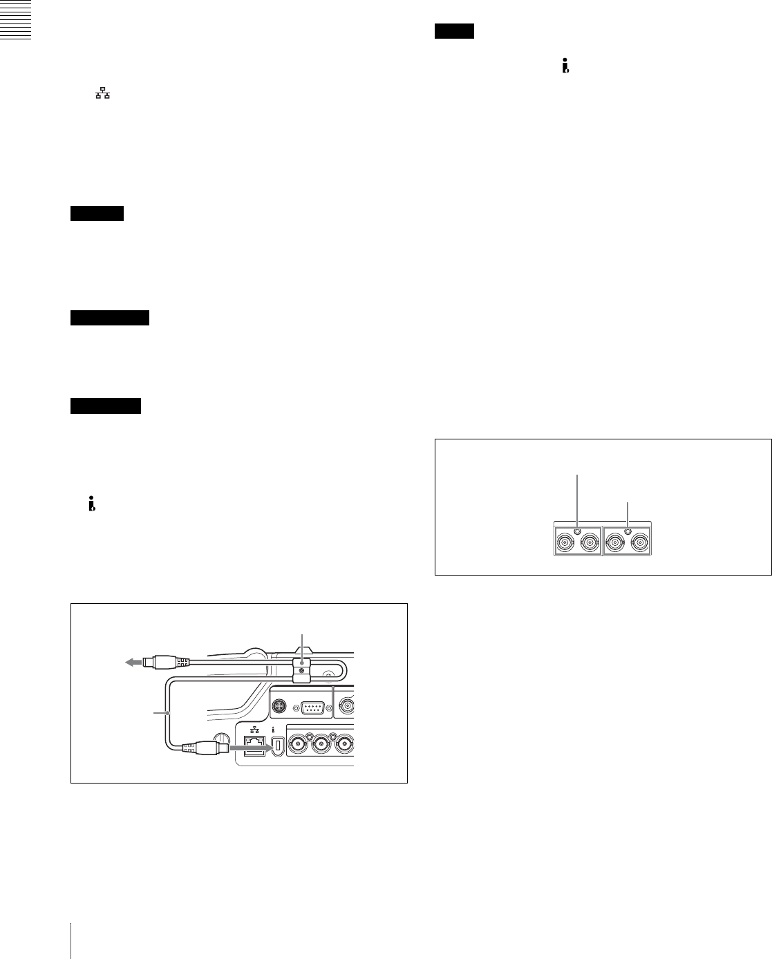
fS400 (i.LINK) connector (6-pin, IEEE1394
compliant)
Connect a DV device, computer, or similar, using an
i.LINK cable. To prevent the connector from coming
loose, we recommend that you secure the cable in the cable
clamp as shown in the following figure.
When the unit is shipped from the factory, the audio output
signal is set to 16 bit/48 kHz/2ch mode. You can change
the audio mode and output channel settings with extended
menu item 831 “DV OUT AUDIO MODE” and extended
menu item 828 “SDI/DV AUDIO OUTPUT SELECT.”
See 7-3-2 “Extended Menu Operations” (page 108) for
more information about how to make these settings.
Notes
• If video or audio signals from an external device
connected with the S400 (i.LINK) connector are not
output, disconnect the i.LINK cable and connect it again,
pushing it straight in.
• When the PDW-R1 is connected to a device with a 6-pin
i.LINK connector by an i.LINK cable, before
unplugging the i.LINK cable, first power off the device
and disconnect the power plug from the outlet. If the
i.LINK cable is unplugged with the device power plug
still connected, a current from an excessive voltage (8 to
40 V) output from the i.LINK connector of the device
flows into the PDW-R1. This may cause a failure of the
PDW-R1.
• When connecting the PDW-R1 to a device with a 6-pin
i.LINK connector, connect to the 6-pin i.LINK
connector of the other device first.
• Except in playback mode (jog and shuttle modes, etc.), if
you are monitoring the audio signal output from this
connector on another device, the audio signal may sound
differently from the audio signal played back on the
PDW-R1.
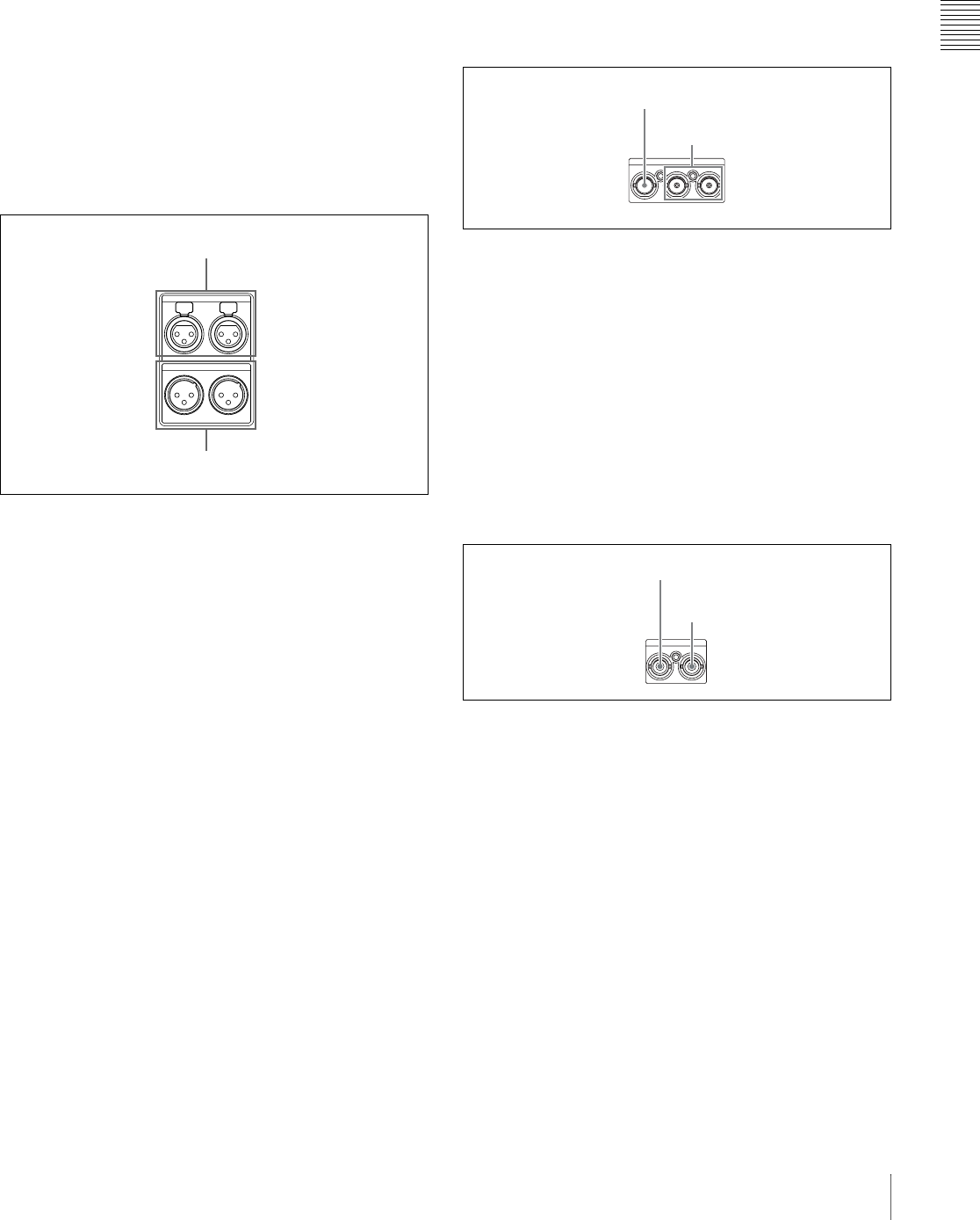
1 Digital audio signal inputs/outputs
aDIGITAL AUDIO (AES/EBU) IN (digital audio
input) 1/2, 3/4 connectors (BNC type)
These input AES/EBU format digital audio signals. The
left connector (1/2) corresponds to audio channels 1 and 2,
and the right connector (3/4) corresponds to audio
channels 3 and 4.
bDIGITAL AUDIO (AES/EBU) OUT (digital audio
output) 1/2, 3/4 connectors (BNC type)
These output AES/EBU format digital audio signals.
When the unit is shipped from the factory, the 1/2
connector is set to audio channel 1/2, and the 3/4 connector
is set to audio channel 3/4. You can change these settings
with extended menu item 827 “AES/EBU AUDIO
OUTPUT SELECT.”
REF VIDE
O
REMOTE
S400
DC OUT 12V
VIDEO
IN OUT1 OUT2(SUPER
To i.LINK (IEEE 1394)
connector of DV device or PC
Cable clamp
i.LINK cable
(not supplied)
DIGITAL AUDIO (AES/EBU)
IN 1/2 3/4 OUT 1/2 3/4
1 DIGITAL AUDIO (AES/EBU) IN 1/2, 3/4 connectors
2DIGITAL AUDIO (AES/EBU)
OUT 1/2, 3/4 connectors
Chapter 2 Names and Functions of Parts
23
2-4 Connectors
To treat the input and output signals of these connectors as
non-audio signals, set the maintenance menu item
“AUDIO CONFIG”-“NON-AUDIO INPUT” (recording)
and extended menu item 823 “NON-AUDIO FLAG PB”
(playback).
See 7-3-2 “Extended Menu Operations” (page 108) for
more information about how to make extended menu
settings.
See 7-4-2 “Maintenance Menu Operations” (page 114)
for more information about how to make maintenance
menu settings.
2 Analog audio signal inputs/outputs
aAUDIO IN (analog audio signal input) 1/3, 2/4
connectors (XLR 3-pin, female)
These input analog audio signals.
With the AUDIO INPUT SEL button (see page 19), you
can select whether the signal input to connector 1/3 is
assigned to audio channel 1or 3, and whether the signal
input to connector 2/4 is assigned to audio channel 2 or 4.
You can set the reference input level with the maintenance
menu item “AUDIO CONFIG.” (Factory default setting:
+4 dB)
For details of the maintenace menu, see 7-4 “Maintenance
Menu” on page 112.
bAUDIO OUT (analog audio signal output) 1/3, 2/4
connectors (XLR 3-pin, male)
These output analog audio signals.
When the unit is shipped from the factory, the 1/3
connector is set to audio channel 1, and the 2/4 connector
is set to audio channel 2. You can change these settings
with extended menu item 824 “ANALOG LINE OUTPUT
SELECT.”
You can set the output level with the maintenance menu
item “AUDIO CONFIG.” (Factory default setting: +4 dB)
Non-audio signals are muted.
You can also output audio monitor signals by setting
extended menu item 820 “AUDIO OUTPUT CH1/CH2
SELECT” to “moni.”
See 7-3-2 “Extended Menu Operations” (page 108) for
more information about how to make these settings.
For details of the maintenace menu, see 7-4 “Maintenance
Menu” on page 112.
3 Analog video signal inputs/outputs
aVIDEO IN (analog video input) connector (BNC
type)
This inputs a composite video signal.
bVIDEO OUT 1, OUT 2 (SUPER) (analog video
output 1, output 2 (superimpose)) connector (BNC
type)
These output composite video signals.
The output from the VIDEO OUT 2 (SUPER) connector
can have time code, menu settings, alarm messages, and
other text information superimposed.
4 SDI signal inputs/outputs
aSDI IN (SDI signal input) connector (BNC type)
This inputs an SDI format video/audio signal.
bSDI OUT (SUPER) (SDI signal output
(superimpose)) connector (BNC type)
This outputs an SDI format video/audio signal.
When the unit is shipped from the factory, audio signal
output is 8 channels with no switching, and RP188 time
code output is set to on. You can change these settings with
extended menu item 828 “SDI/DV AUDIO OUTPUT
SELECT” and extended menu item 920 “SD-SDI H-ANC
CONTROL.”
The output can have time code, menu settings, alarm
messages, and other text information superimposed. To
turn superimposition off, set the maintenance menu item
“OTHERS”-“SDI SUPER” to “OFF.”
To treat the input and output signals of these connectors as
non-audio signals, set the maintenance menu item
AUDIO OUT
1/3 2/4
1/3 2/4
AUDIO IN
1 AUDIO IN 1/3, 2/4 connectors
2 AUDIO OUT 1/3, 2/4 connectors
VIDEO
IN OUT1 OUT2(SUPER)
1 VIDEO IN connector
2VIDEO OUT 1, OUT 2
(SUPER) connectors
SDI
IN OUT(SUPER)
1 SDI IN connector
2SDI OUT (SUPER)
connector
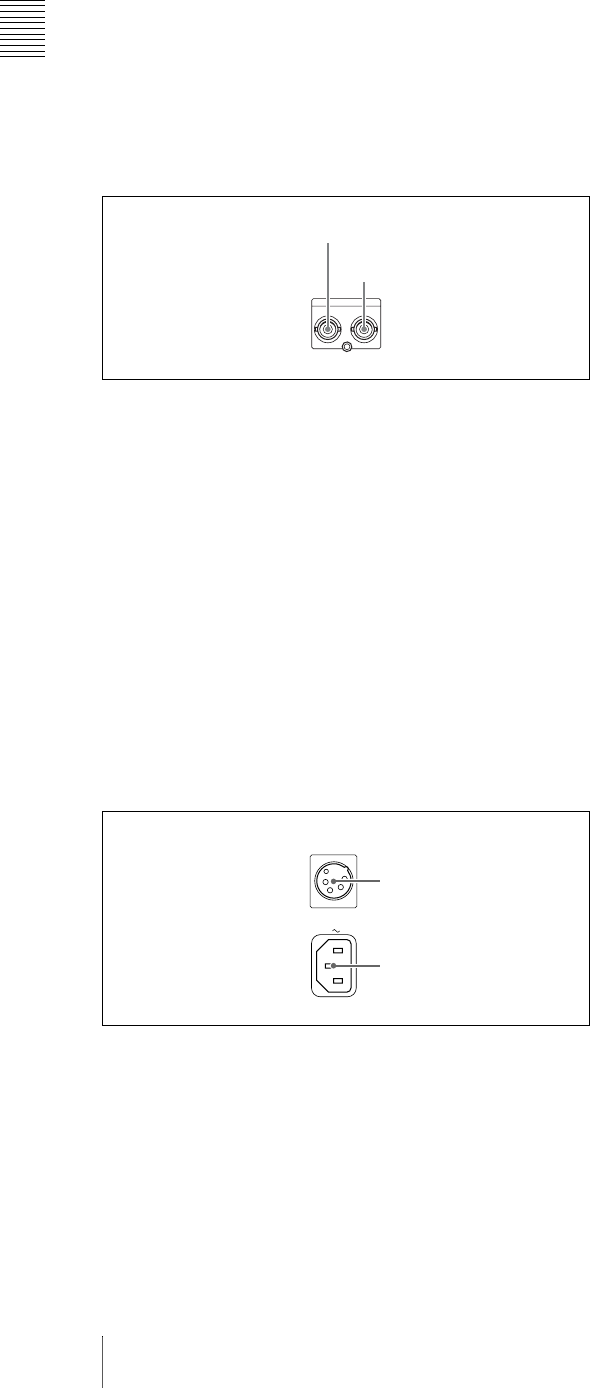
Chapter 2 Names and Functions of Parts
24 2-4 Connectors
“AUDIO CONFIG”-“NON-AUDIO INPUT” (recording)
and extended menu item 823 “NON-AUDIO FLAG PB”
(playback).
See 7-3-2 “Extended Menu Operations” (page 108) for
more information about how to make extended menu
settings.
See 7-4-2 “Maintenance Menu Operations” (page 114)
for more information about how to make maintenance
menu settings.
5 Time code inputs/outputs
aTC IN connector (BNC type)
This inputs an SMPTE time code generated by an external
device.
bTC OUT connector (BNC type)
This outputs the following time code, depending on the
operating state of the PDW-R1.
During playback: playback time code
During recording: the time code from the internal time
code generator or the time code input to the TC IN
connector.
When extended menu item 611 “TC OUTPUT
PHASE IN EE MODE” is set to “muting,” no time
code is output.
6 Power supply section
a DC IN (DC power input) 12V connector (XLR
type, 4-pin, male)
Connect DC power to this connector.
b-AC IN (AC power input) connector
Connect to an AC power supply, using an optional power
cord (see page 133).
TC
IN OUT
1 TC IN connector
2 TC OUT connector
AC IN
DC IN
12V
1 DC IN 12V connector
2 -AC IN connector
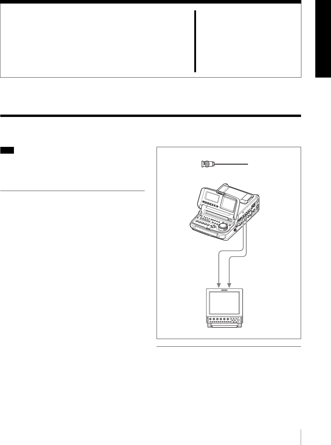
25
3-1 Connections and Settings
Chapter3
Preparations
3-1 Connections and Settings
Note
Production of some of the peripherals and related devices
described in this chapter has been discontinued. For advice
about choosing devices, please contact your Sony dealer or
a Sony sales representative.
3-1-1 Connecting an External
Monitor
Connecting a Sony LCD monitor to the VIDEO OUT 1,
VIDEO OUT 2 (SUPER), or SDI OUT (SUPER)
connector of this unit enables you to see the output video
on the monitor screen.
To superimpose text information, for example, time code
and alarm messages, use the VIDEO OUT 2 (SUPER) or
SDI OUT (SUPER) connector. You can select the kind of
text information to display using basic menu item 005
“DISPLAY INFORMATION SELECT.”
For detailed information about basic menu items and how
to make menu settings, see 7-2 “Basic Setup Menu” on
page 90.
Connect a video monitor as example 1 or 2 shown in the
following figure.
3-1-2 Connections for Using PDZ-1
Proxy Browsing Software
Using the supplied PDZ-1 Proxy Browsing Software, you
can carry out simple editing with proxy AV data.
For an overview of PDZ-1 and how to install the software,
see 5-4 “Using PDZ-1 Proxy Browsing Software” on page
SDI
12
SDI OUT
(SUPER)
VIDEO OUT 2 (SUPER)
PDW-R1
1, 2: 75 Ω coaxial cable (not supplied)
To SDI IN-1/IN-2 connectorTo LINE A/B connector
LMD-9030 LCD monitor
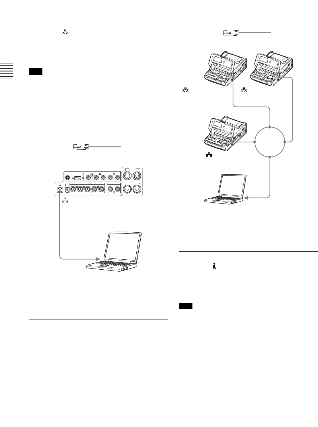
Chapter 3 Preparations
26 3-1 Connections and Settings
71.
For information about how to use the software, refer to the
Help provided in the software.
Using the (network) connector (FTP
connection)
The following shows an example of an FTP (File Transfer
Protocol) connection.
Note
To use PDZ-1 requires the PDW-R1 IP address and other
network-related settings to be made beforehand.
For details of the network-related settings, see “To change
network settings” (page 115).
Using the S400 (i.LINK) connector (FAM
connection)
The following shows an example of a FAM (file access
mode) connection.
Note
The PDZ-1 Proxy Browsing Software must be installed in
advance.
The required FAM driver is also installed when you install
the PDZ-1 software.
See 5-4 “Using PDZ-1 Proxy Browsing Software” (page
71) for more information about installing the PDZ-1
software.
Some limitations apply to FAM connections. For details,
see 6-2 “File Access Mode File Operations” (page 78).
REF VIDEO INREMOTE DIGITAL AUDIO (AES/EBU)
S400
IN
DC OUT 12V 1/2 3/4 OUT 1/2 3/4
SDI
IN OUT(SUPER)
VIDEO
IN OUT1 OUT2(SUPER)
TC
IN OUT
AUDIO OUT
1/3 2/4
1/3 2/4
AUDIO IN
1
PDW-R1
Laptop computer
(network) connector
To network connector
Connecting this unit directly to a laptop computer
1: Network cable (not supplied) a)
Make sure the remote control switch (see page 12) is set to
“NETWORK” and extended menu item 257 “NETWORK
ENABLE” is set to “net.”
a) Use a cross cable.
PDW-R1
PDW-R1
PDW-R1
LAN
1
1
1
1
1: Network cable (not supplied) a)
Laptop computer
(network) connector
To network connector
Connecting three PDW-R1 units to a laptop computer via a
LAN.
Make sure the remote control switch (see page 12) is set to
“NETWORK” on each of the three PDW-R1 units and extended
menu item 257 “NETWORK ENABLE” is set to “net.”
a) Use a straight cable.
(network) connector
(network) connector
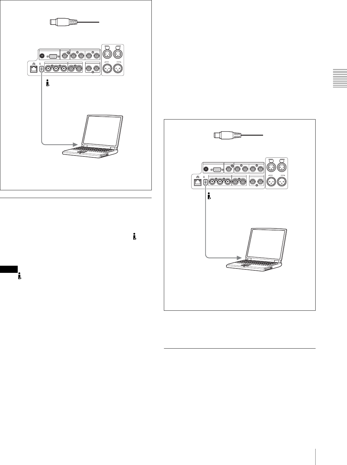
Chapter 3 Preparations
27
3-1 Connections and Settings
3-1-3 Connecting to a Nonlinear
Editing System
You can send video/audio signals (AV/C data) from this
unit to a nonlinear editing system connected to the S400
(i.LINK) connector.
The following figure shows an example connection.
Notes
• The S400 (i.LINK) connector of this unit outputs
video/audio signals in DVCAM format. Data recorded in
MPEG IMX format is output after being converted into
DVCAM format.
• The nonlinear editing system to be used being connected
to this unit requires editing software (not supplied)
supporting DVCAM format.
• Make the following settings before transferring video/
audio signals (AV/C data) from this unit to a nonlinear
editing system.
Audio mode selection
Use extended menu item 831 “DV OUT AUDIO
MODE” to select either of the following.
4ch: 12 bit/32 kHz/4ch
2ch: 16 bit/48 kHz/2ch (Factory default setting)
Audio output channel selection
Select the audio output channels with extended menu
item 828 “SDI/DV AUDIO OUTPUT SELECT.”
For information about how to make extended menu item
settings, see 7-3-2 “Extended Menu Operations” on
page 108.
For the method of transferring video/audio signals (AV/C
data) to a nonlinear editing system, refer to the manual
provided with the editing software to be used.
3-1-4 Connections for Recording in
Parallel With a Camcorder
You can start and stop recording on this unit at the same
time that recording starts and stops on a camcorder. This
allows you to make a backup recording of the video and
audio shot by the camcorder. The following figure shows
an example of the connections to make.
REF VIDEO INREMOTE DIGITAL AUDIO (AES/EBU)
S400
IN
DC OUT 12V 1/2 3/4 OUT 1/2 3/4
SDI
IN OUT(SUPER)
VIDEO
IN OUT1 OUT2(SUPER)
TC
IN OUT
AUDIO OUT
1/3 2/4
1/3 2/4
AUDIO IN
1
PDW-R1
1: i.LINK cable (not supplied)
Laptop computer
To i.LINK (IEEE1394)
connector
Make sure extended menu item 215 “i.LINK MODE” is set to
“FAM (PC REMOTE).”
S400 (i.LINK)
REF VIDEO INREMOTE DIGITAL AUDIO (AES/EBU)
S400
IN
DC OUT 12V 1/2 3/4 OUT 1/2 3/4
SDI
IN OUT(SUPER)
VIDEO
IN OUT1 OUT2(SUPER)
TC
IN OUT
AUDIO OUT
1/3 2/4
1/3 2/4
AUDIO IN
1
PDW-R1
1: i.LINK cable (not supplied)
To i.LINK(IEEE1394)
connector
Laptop computer
(With editing software supporting
DVCAM format installed)
Make sure extended menu item 215 “i.LINK MODE” is set to
“AV/C.”
S400 (i.LINK)
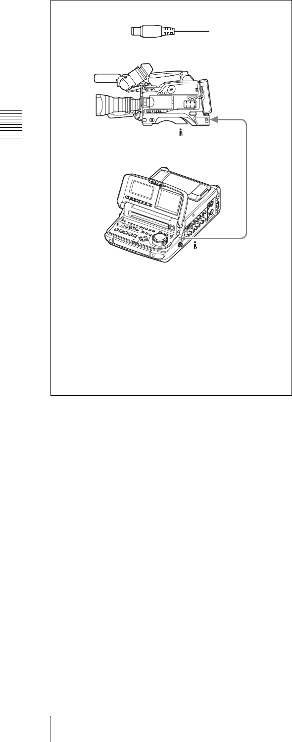
Chapter 3 Preparations
28 3-1 Connections and Settings
SDI
PDW-R1
(i.LINK) DV OUT
1
S400 (i.LINK)
1: i.LINK cable (not supplied)
DSR-400/400P/450WS/450WSP settings
REC TRIGGER switch: INT ONLY
“REC FORMAT” on the VTR MODE page of the
MAINTENANCE menu: DVCAM
PDW-R1 settings
Remote control switch (see page 12): REMOTE
VIDEO INPUT SEL button (see page 19): select i.LINK
Basic menu item 031 “RECORDING FORMAT”: DVCAM
Extended menu item 214 “REMOTE INTERFACE”: i.LINK
Extended menu item 215 “i.LINK MODE”: AV/C
Extended menu item 216 “PARALLEL RECORDING MODE”:
on
DSR-400/400P/450WS/450WSP
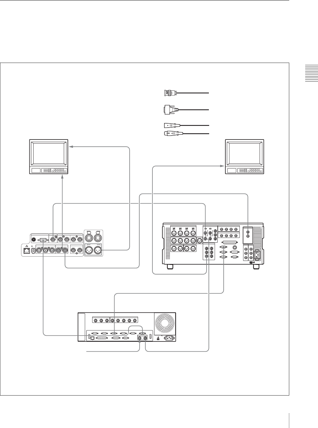
Chapter 3 Preparations
29
3-1 Connections and Settings
3-1-5 Connections for Cut Editing
By connecting this unit to a VTR (for example, MSW-
M2000/M2000P or DSR-2000/2000P) and an editing
control unit, you can make up a cut editing system. Some
example connections are shown in the following.
When making the connections, also refer to the manuals
provided with the equipment to be connected.
See page 32 for more information about editing control
unit settings.
When using an editing control unit
AC IN
REF VIDEO INREMOTE DIGITAL AUDIO (AES/EBU)
S400
IN
DC OUT 12V 1/2 3/4 OUT 1/2 3/4
SDI
IN OUT(SUPER)
VIDEO
IN OUT1 OUT2(SUPER)
TC
IN OUT
AUDIO OUT
1/3 2/4
1/3 2/4
AUDIO IN
REF VIDEO
IN
REF. VIDEO
INPUT
VIDEO OUT 2
(SUPER)
SDI OUT (SUPER)
SDI INPUT
REMOTE 1 IN (9P)
REF VIDEO IN
PLAYER-1
RECORDER
BVE-700
COMPOSITE VIDEO
OUTPUT 3 (SUPER)
AUDIO
OUT
REMOTE
2
2
1
1
11
1
3
PDW-R1
Cut editing system comprising this unit as a player, an
MSW-M2000/M2000P unit as a recorder, and a BVE-700
editing control unit.
1: 75 Ω coaxial cable (not supplied)
2: 9-pin remote control cable (not supplied)
3: Cable with XLR connectors (not supplied) a)
Video monitor Video monitor
To composite video
input connector
To analog audio input connector
To composite video input connector
Reference video signal
MSW-M2000/M2000P (recorder) settings
REMOTE 1(9P) button: Lit
For details about the settings of the MSW-M2000/M2000P, refer
to the operation manual for the unit.
PDW-R1 (player) settings
Remote control switch (see page 12): REMOTE
Extended menu item 214 “REMOTE INTERFACE”: 9PIN
Extended menu item 820 “AUDIO OUTPUT CH1/CH2 SELECT”:
moni
a) Use an XLR/pin converter plug (not supplied) as required.
MSW-M2000/M2000P
(recorder)
(player)
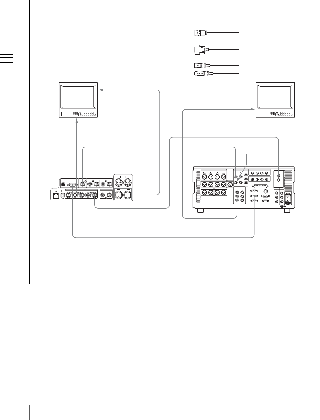
Chapter 3 Preparations
30 3-1 Connections and Settings
When using the editing functions of the recorder
REF VIDEO INREMOTE DIGITAL AUDIO (AES/EBU)
S400
IN
DC OUT 12V 1/2 3/4 OUT 1/2 3/4
SDI
IN OUT(SUPER)
VIDEO
IN OUT1 OUT2(SUPER)
TC
IN OUT
AUDIO OUT
1/3 2/4
1/3 2/4
AUDIO IN
REMOTE 1 OUT (9P)
REMOTE
PDW-R1
2
REF VIDEO
IN
REF. VIDEO
INPUT
VIDEO
OUT 2
(SUPER)
SDI OUT (SUPER)
SDI INPUT
COMPOSITE VIDEO
OUTPUT 3 (SUPER)
AUDIO
OUT
1
11
1
3
1: 75 Ω coaxial cable (not supplied)
2: 9-pin remote control cable (not supplied)
3: Cable with XLR connectors (not supplied) a)
MSW-M2000/M2000P
(recorder)
Video monitor Video monitor
To composite video
input connector
To analog audio input connector
To composite video input connector
Connections using the REMOTE connector (D-sub 9-pin):
Cut editing system comprising this unit as a player and an MSW-
M2000/M2000P unit as a recorder. For cut editing, the system uses
the editing functions of the recorder.
MSW-M2000/M2000P (recorder) settings
REMOTE 1(9P) button: Unlit
For details about the settings of the MSW-M2000/M2000P, refer
to the operation manual for the unit.
PDW-R1 (player) settings
Remote control switch (see page 12): REMOTE
Extended menu item 214 “REMOTE INTERFACE”: 9PIN
Extended menu item 820 “AUDIO OUTPUT CH1/CH2 SELECT”:
moni
a) Use an XLR/pin converter plug (not supplied) as required.
Reference video
signal
(player)
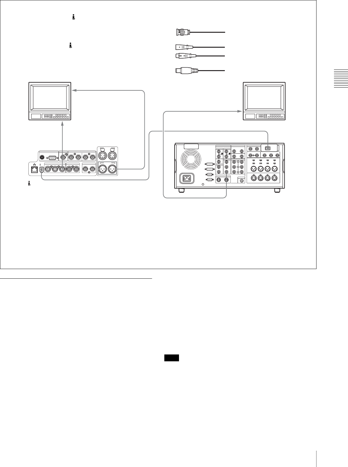
Chapter 3 Preparations
31
3-1 Connections and Settings
3-1-6 Using the RM-280 Editing
Controller
You can connect an RM-280 Editing Controller to this unit
and use it as an editor or as a remote controller.
Using the RM-280 as an editor
You can perform assemble and insert editing by
connecting this unit, a VTR, and an RM-280 Editing
Controller.
When configuring an editing system that includes this unit
and another VTR, use this unit as the player (feeder).
For information about connections, refer to the Operation
Manual for the RM-280.
RM-280 settings
EDITOR/REMOTE CONTROL switch: EDITOR
Setup menu item 11 “P ST DLY”: LEARN
For settings on the recorder VTR, refer to the Operation
Manual for the RM-280.
PDW-R1 settings
Remote control switch (see page 12): REMOTE
Extended menu item 214 “REMOTE INTERFACE”:
9PIN
Note
The RM-280 has not memorized the start delay of this unit.
Before editing, have the RM-280 memorize the start delay
of this unit. (Use the learn function of the RM-280.)
Using the RM-280 as a remote controller
You can connect this unit to the RM-280 with an optional
9-pin remote cable to perform editing operations such as
thumbnail search, scene selection, and essence mark
REF VIDEO INREMOTE DIGITAL AUDIO (AES/EBU)
S400
IN
DC OUT 12V 1/2 3/4 OUT 1/2 3/4
SDI
IN OUT(SUPER)
VIDEO
IN OUT1 OUT2(SUPER)
TC
IN OUT
AUDIO OUT
1/3 2/4
1/3 2/4
AUDIO IN
VIDEO OUT 2
(SUPER)
VIDEO OUT 3 (SUPER)
AUDIO
OUT
13
2
S400 (i.LINK)
1
PDW-R1
Connections using the S400 (i.LINK) connector:
Cut editing system comprising this unit as a player and a DSR-
2000/2000P unit as a recorder. For cut editing, the system uses
the editing functions of the recorder. In this system, all signals
such as the video/audio signals and control signals are
transferred through the S400 (i.LINK) connector.
i.LINK (optional DSBK-190)
(player)
Video monitor Video monitor
To composite video
input connector
To analog audio input connector
To composite video input
connector
DSR-2000/2000P
(recorder)
DSR-2000/2000P (recorder) settings
i.LINK button: Lit
SDTI/i.LINK button: i.LINK
For details about the settings of the DSR-2000/2000P, refer to the
operating instructions for the unit.
PDW-R1 (player) settings
Remote control switch (see page 12): REMOTE
Extended menu item 214 “REMOTE INTERFACE”: i.LINK
Extended menu item 820 “AUDIO OUTPUT CH1/CH2 SELECT”:
moni
a) Use an XLR/pin converter plug (not supplied) as required.
1: 75 Ω coaxial cable (not supplied)
3: i.LINK cable (not supplied)
2: Cable with XLR connectors (not supplied) a)

Chapter 3 Preparations
32 3-1 Connections and Settings
recording from the RM-280 (when XDCAM mode is
selected).
RM-280 settings
EDITOR/REMOTE CONTROL switch: REMOTE
CONTROL
Setup menu item 19 “FNC MODE”: XDCAM
For information about function assignments to PF keys in
XDCAM mode, refer to the Operation Manual for the RM-
280.
PDW-R1 settings
Remote control switch (see page 12): REMOTE
Extended menu item 214 “REMOTE INTERFACE”:
9PIN
3-1-7 Editing Control Unit Settings
When connecting an editing control unit to use with this
unit, make the following settings, depending on the editing
control unit model.
BVE-600/700/900/910/2000/9100
Set VTR constants as follows.
FXE-100/120
Set VTR constants as follows.
RM-450
Set the DIP switches as follows.
• Left switch
• Right switch
PVE-500
No settings required.
Line
mode
VTR CONSTANT 1
12345678
525/60 A0 92 00 96 05 05 03 80
625/50 A1 92 00 7D 05 05 03 80
Line
mode
VTR CONSTANT 2
12345678
525/60 0A 07 FE 00 80 5A FF 5A
625/50 0A 07 FE 00 80 4C FF 4B
Line
mode
12345678
525/60 A0 92 00 96 05 05 03 80
625/50 A1 92 00 7D 05 05 03 80
Line
mode
9 101112131415
525/60 0A 07 FE 00 80 5A FF
625/50 0A 07 FE 00 80 4C FF
Line
mode
76543210
525/60OFF––OFF––––
625/50OFF––OFF––––
Line
mode
76543210
525/60 OFF– OFFON OFFOFFON ON
625/50 ON – OFF ON OFF OFF ON ON
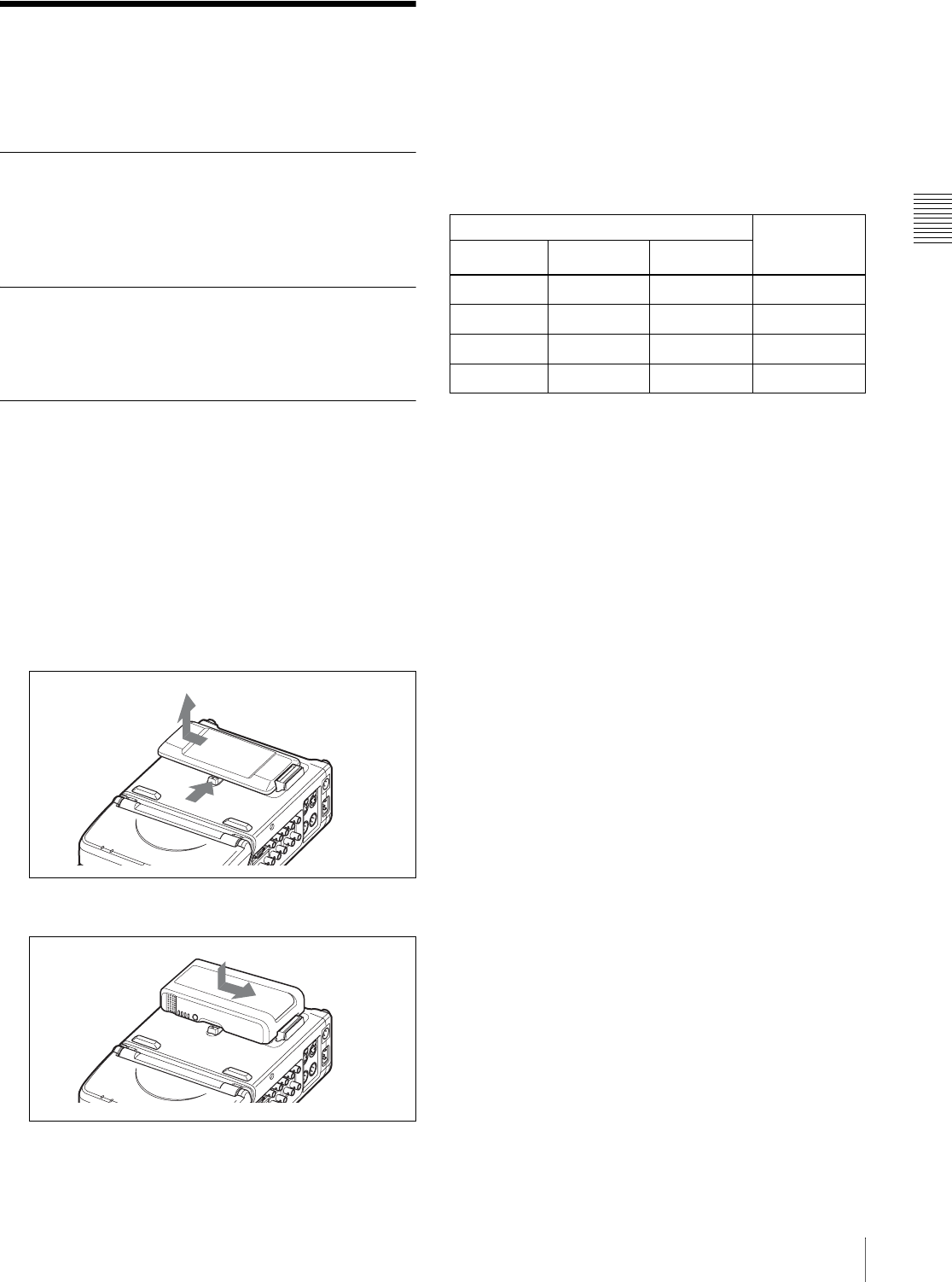
Chapter 3 Preparations
33
3-2 Power Preparations
3-2Power Preparations
This unit can be powered by a battery pack, DC power, or
AC power.
3-2-1 Using AC Power
Connect an AC power source (100 V to 240 V AC, 50/60
Hz) to the ~ AC IN connector on the right side of the unit
with an AC power cord (not supplied, see page 133).
3-2-2 Using DC Power
Connect a DC power source to the DC IN 12V connector
on the right side of the unit.
3-2-3 Using a Battery Pack
Usable battery packs
The battery packs usable with this unit are as follows.
BP-GL95, BP-GL65, BP-L80S, BP-L60S
To attach a battery pack
Proceed as follows.
1
Remove the cover of the battery pack shoe.
2
Fit the battery pack.
To remove the battery pack
Follow the above procedure in the reverse flow. After the
battery pack is removed, replace the cover of the battery
pack shoe.
When several power sources are
connected
The following table shows the automatically selected
power source that drives this unit.
a) Switches to DC power immediately if AC power supply is interrupted.
b) Switches to battery pack power immediately if AC power supply is
interrupted.
c) Does not switch to battery pack power, even if DC power supply is
interrupted. To drive this unit from the battery pack, disconnect the DC
power connector from the DC IN 12V connector.
SDI
2
1
SDI
Power types Power that
drives this
unit
AC power DC power Battery pack
Connected Connected Mounted AC power a)
Connected Connected – AC power a)
Connected – Mounted AC power b)
– Connected Mounted DC power c)
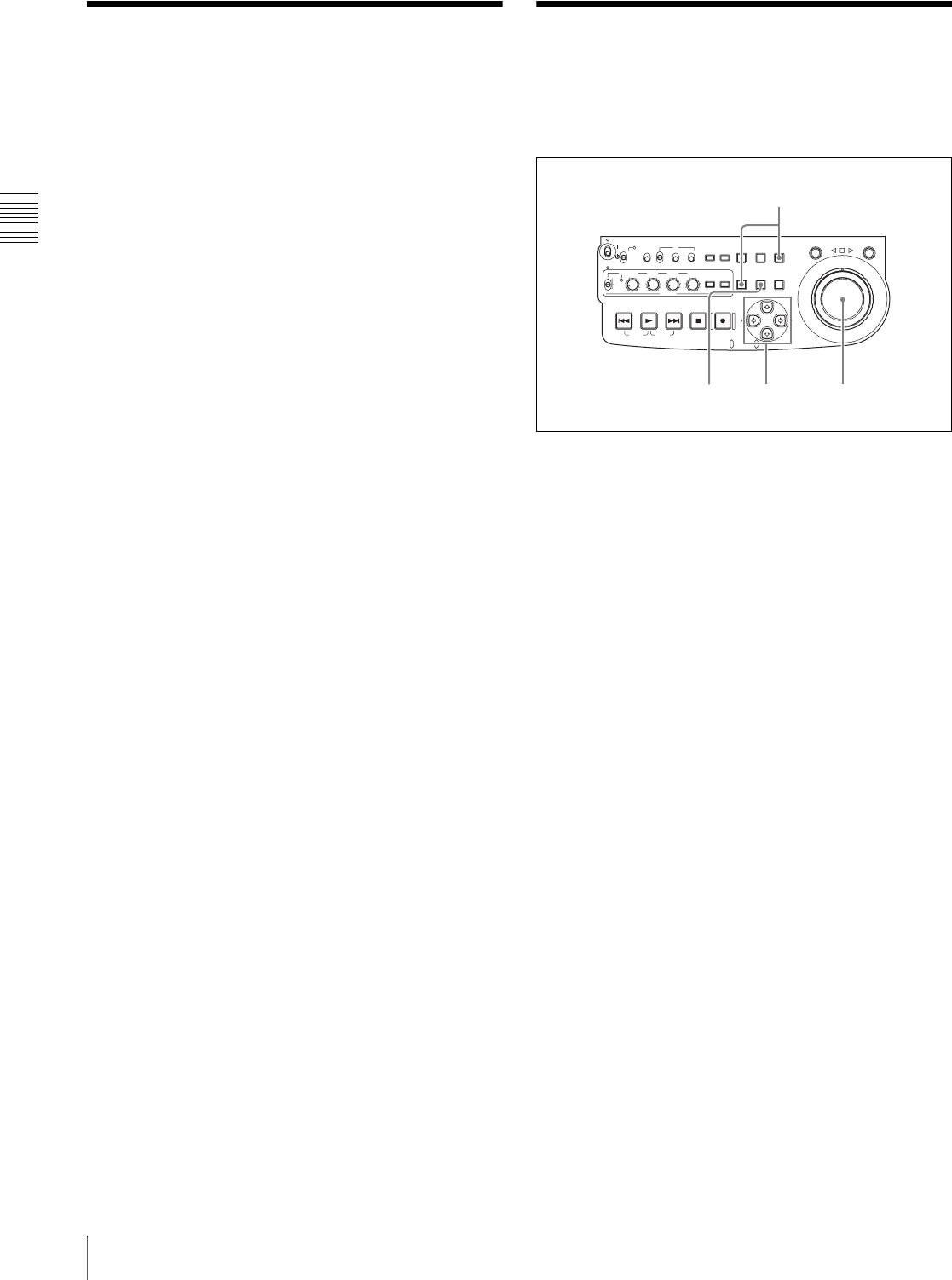
34 3-3 Setup / 3-4 Setting the Date and Time
Chapter 3 Preparations
3-3Setup
The principal setup operations before operating this unit
can be carried out using setup menus.
The setup menus of this unit comprise a basic setup menu
and an extended setup menu. The contents of these menus
are as follows.
Basic setup menu:
• Items relating to the hours meter
• Items relating to operation
• Items relating to menu banks
Extended setup menu:
• Items relating to control panels
• Items relating to the remote control interface
• Items relating to editing operations
• Items relating to preroll
• Items relating to disc protection
• Items relating to the time code, metadata, and UMID
• Items relating to video control
• Items relating to audio control
• Items relating to digital processing
For detailed information about the items, except for the
basic menu items relating to the hours meter, of these
menus and how to use them, see Chapter 7 “Menus” (page
89). For detailed information about menu operations
relating to the hours meter, see 8-1-1 “Digital Hours
Meter” (page 120).
This unit allows four different sets of menu settings to be
saved in what are termed “menu banks” numbered 1 to 4.
Saved sets of menu settings can be recalled for use as
required.
For more information about the menu banks, see “Menu
bank operations (menu items B01 to B13)” (page 96) and
the description of maintenance menu item “SETUP
MAINTENANCE” — “SETUP BANK4” (page 113).
3-4 Setting the Date and
Time
When using this unit for the first time, you should set the
date and time as follows.
1
Holding down the SHIFT button, press the MENU
button.
The system menu appears on the video panel.
2
Select “DATE/TIME PRESET” using the F button or
f button, then press the g button.
The date and time setting screen appears on the
monitor, allowing you to set the following items.
• YEAR: Calendar year
• MONTH: Month
• DAY: Day
• TIME: Time
• TIME ZONE: Time zone (Difference from UTC)
3
Set the date, time and time zone.
You can change the setting of the flashing digits.
To change the flashing digits
Use the arrow buttons (G, g).
To increase or decrease the values of the flashing
digits
Use the arrow buttons (F, f) or jog dial.
4
Press the SET button.
The date, time and time zone settings are stored.
To return to the previous menu page
Press the MENU button.
To exit the menu
Press the MENU button twice in succession.
ACCESS
SHUTTLE JOG
THUMB
NAIL
ESSENCE
MARK
MENU
S.SEL
SET RESET
SHIFT
TOP F REV
ALL/CH-1 CH-2 CH-3 CH-4
TC
F FWD
AUDI O
END
REC
PRESET
VARIABLE
PB
PREV NEXTPLAY STOP REC
CLIP
MENU
SYSTEM
MENU
MONITOR
SEL
METER
SEL
HOLD
COUNTER
SEL
SUB
CLIP
MARK1
MARK2
IN OUT
KEY INHI
ON
OFF
NETWORK
LOCAL
REMOTE
F-RUN
R-RUN
PRESET
REGEN
INT
EXT
RP188
L/ST/R
32,34
1
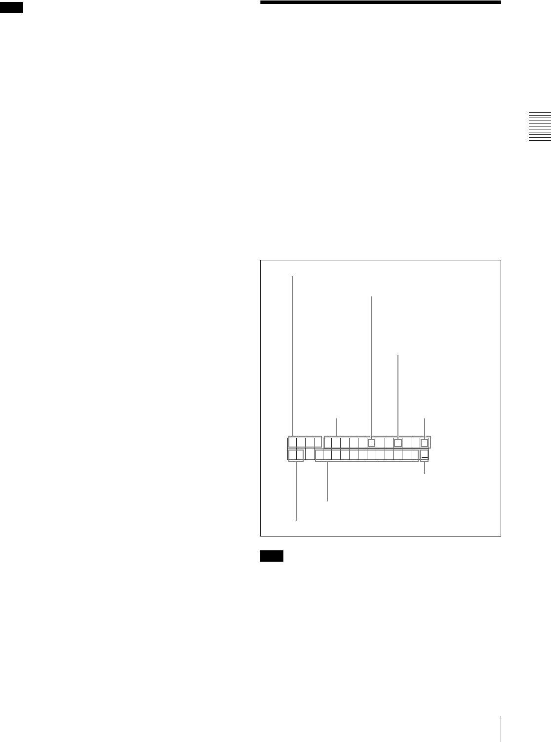
Chapter 3 Preparations
35
3-5 Superimposed Text Information
Note
The time zone is reset to the factory default when you
execute the maintenance menu item “RESET ALL
SETUP.” You will need to set it again. The date and time
are not reset.
3-5Superimposed Text
Information
The video signal output from the VIDEO OUT 2 (SUPER)
connector or the SDI OUT (SUPER) connector contains
superimposed text information, including time code, menu
settings, and alarm messages.
Adjusting the text display
You can adjust the position, size and type of the
superimposed text using basic menu items 002, 003, 005,
009, 011, and 012.
For details, see 7-2-1 “Items in the Basic Setup Menu”
(page 90).
Information displayed
Note
The display shown above corresponds to the factory
default settings of the unit. You can change the type of
information to be displayed in the lower line of the display
by changing the setting of basic menu item 005
“DISPLAY INFORMATION SELECT.”
For details, see 7-2-1 “Items in the Basic Setup Menu”
(page 90).
TCR 00:04.47.07*
B1 PLAY LOCK
5Menu setting states
1Type of time data
2Time code reader drop frame
mark (for 525 line mode only)
3Time code generator drop
frame mark (for 525 line
mode only)
4VITC field mark
Time data
7Playback condition
mark
6Operation mode
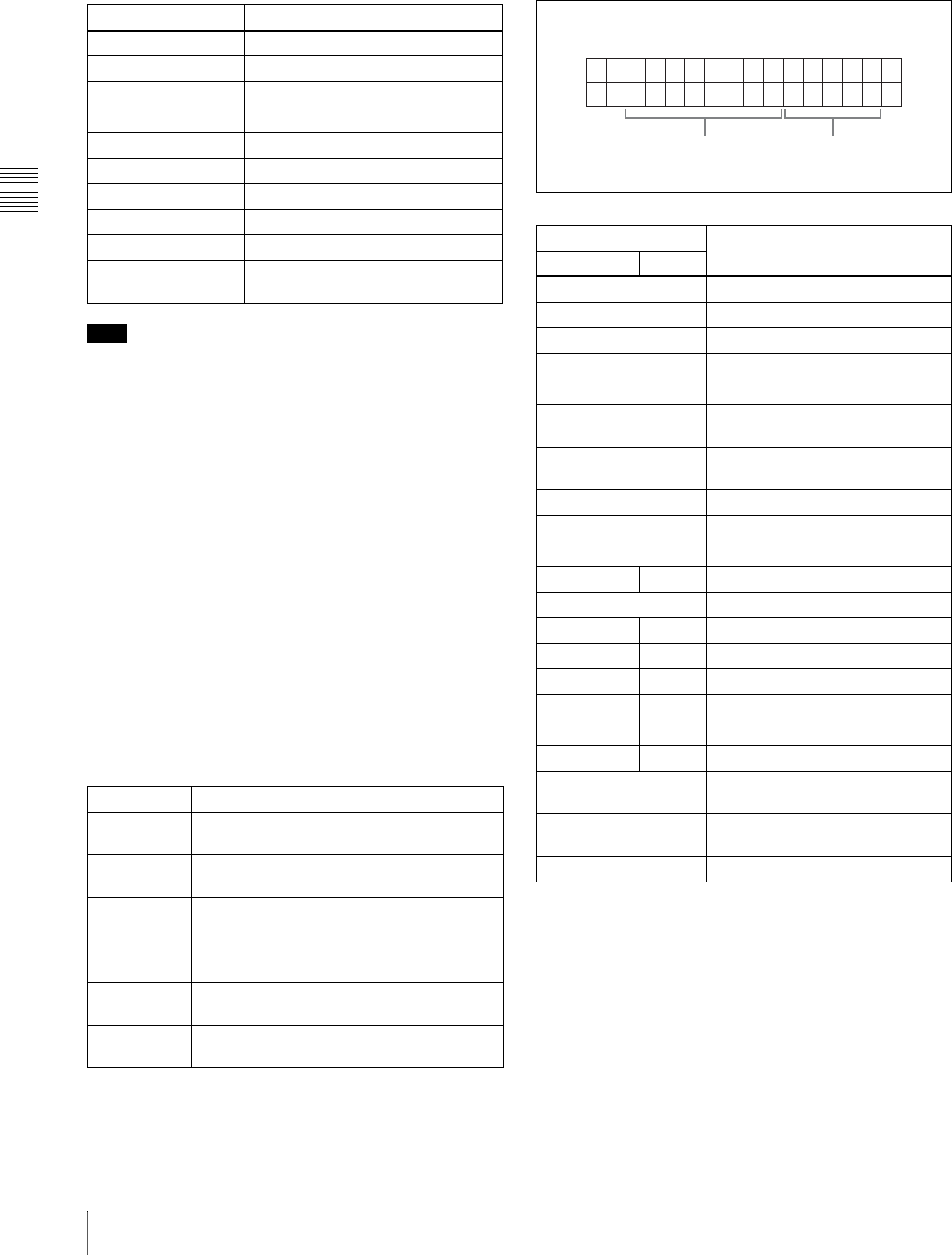
Chapter 3 Preparations
36 3-5 Superimposed Text Information
aType of time data
Note
If the time data or user’s bits cannot be read correctly,
they will be displayed with an asterisk. For example,
“T*R”, “U*R”, “T*R.” or “U*R.”.
bTime code reader drop frame mark (for 525 line
mode only)
“.”: Indicates drop frame mode
“:”: Indicates non-drop-frame mode
cTime code generator drop frame mark (for 525 line
mode only)
“.”: Indicates drop frame mode (factory default setting)
“:”: Indicates non-drop-frame mode
dVITC field mark
“ ” (blank): Fields 1 and 3 (for 525/60 mode) or fields 1, 3,
5 and 7 (for 625/50 mode)
“ * ”: Fields 2 and 4 (for 525/60 mode) or fields 2, 4, 6 and
8 (for 625/50 mode)
eMenu setting states
fOperation mode
The field is divided into two blocks as shown below.
• Block A displays the operation mode.
• Block B displays the servo lock status or playback speed.
gPlayback condition mark
One of three channel condition marks is displayed when
the ACCESS indicator is lit during any mode except
recording. The three channel condition marks indicate the
following three stages.
Display Meaning
CNT Counter data
TCR TC reader time code data
UBR TC reader user bits data
TCR. VITC reader time code
UBR. VITC reader user bits data
TCG TC generator time code
UBG TC generator user bits data
IN IN point time data
OUT OUT point time data
DUR Duration between IN point and OUT
point
Display Description
B1 The current menu settings are the same as
the settings in menu bank 1.
B2 The current menu settings are the same as
the settings in menu bank 2.
B3 The current menu settings are the same as
the settings in menu bank 3.
B4 The current menu settings are the same as
the settings in menu bank 4.
DF The current menu settings are the same as
the factory defaults.
No display The current menu settings are different from
all of the above.
Display Operation mode
Block A Block B
DISC OUT Disc is not loaded.
LOADING Disc is being loaded.
UNLOADING Disc is being unloaded.
STANDBY OFF Standby off mode
STOP Stop mode
NEXT Cuing up to the first frame of the
next clip.
PREV Cuing up to the first frame of the
current clip.
F.FWD Fast forward search
F.REV Fast reverse search
PLAY Playback mode (servo unlocked)
PLAY LOCK Playback mode (servo locked)
REC Record mode (servo unlocked)
REC LOCK Record mode (servo locked)
JOG STILL A still picture in jog mode
JOG FWD Jog mode in forward direction
JOG REV Jog mode in reverse direction
SHUTTLE STILL A still picture in shuttle mode
SHUTTLE (Speed) Shuttle mode
TOP 001/xxx Cuing up to the first frame of the
first clip.
END xxx/xxx Cuing up to the last frame of the
last clip.
PREROLL Cuing up during thumbnail search
BA

Chapter 3 Preparations
37
3-5 Superimposed Text Information
a) Read errors will occur if the playback condition continues to deteriorate.
If a read error occurs, a “Disc Error!” alarm appears in the time data
display, the picture freezes, and audio is muted.
To display playback condition marks, set basic menu item
012 “CONDITION DISPLAY ON VIDEO MONITOR”
to “ena,” and set basic menu item 005 “DISPLAY
INFORMATION SELECT” to “T&sta.”
For details about operation, see 7-2-2 “Basic Menu
Operations” (page 94).
Playback condition displays
You can be alerted in advance to deteriorating playback
conditions and to error correction rates which are
approaching their limits.
Deteriorating playback may be due to the following
causes.
• Scratches and dust on the disc surface
This includes fingerprints, dust from the air, tar from
cigarette smoke, and so on.
Scratches and soiling which occur before recording are
not a problem because they are registered in advance as
defects, and recording avoids them. However, scratches
and soiling which occur after recording can lead to
deteriorating playback conditions.
• Aging of disc recording layers
Over several decades, the recording layers of optical
discs can age and cause deteriorating playback
conditions.
You can use this function to check archival discs and
other discs which have been stored for extended periods,
so that you can take action before the deterioration
progresses further.
• Deteriorating laser diodes performance
The performance of the laser diodes used in optical
heads can worsen with age, leading to deteriorating
playback conditions.
You can use the digital clock to check the total optical
output time of optical heads.
For details, see 8-1-1 “Digital Hours Meter” (page 120)
about this setting.
Refer to the Maintenance Manual for an approximate
guide to when it is time to replace optical heads.
To prevent playback conditions from
deteriorating
Pay attention to the following points when handling discs.
• Do not open disc cartridges and touch discs directly with
your hands.
• Do not store for long periods in locations which are
dusty or exposed to air circulated by fans.
• Do not store for long periods under high temperatures or
in locations exposed to direct sunlight.
If playback conditions have deteriorated
If a yellow or red playback condition mark appears, check
the following points.
Whether the disc displays the same playback condition
on other XDCAM devices: If so, the surface of the
disc may be dirty or scratched, or the performance of
the recording layers on the disc may have worsened
due to age. Do not use discs with these symptoms.
Whether every disc inserted into an XDCAM device
displays the same playback conditions: If so, the
performance of the laser diodes may have deteriorated.
Check the total optical output time.
Display Name Description
Green condition There is no problem with the
playback condition. This unit
and the disc can be used just
as they are. This
corresponds to the “green”
channel condition indicator of
a VTR.
Yellow condition The playback condition has
deteriorated to some degree.
There are no read errors, but
you should take the action
described in the next section.
This corresponds to the
“yellow” channel condition
indicator of a VTR.
Red condition The playback condition has
deteriorated. There are no
read errors,a) but you should
take the action described in
the next section. This
corresponds to the “red”
channel condition indicator of
a VTR.
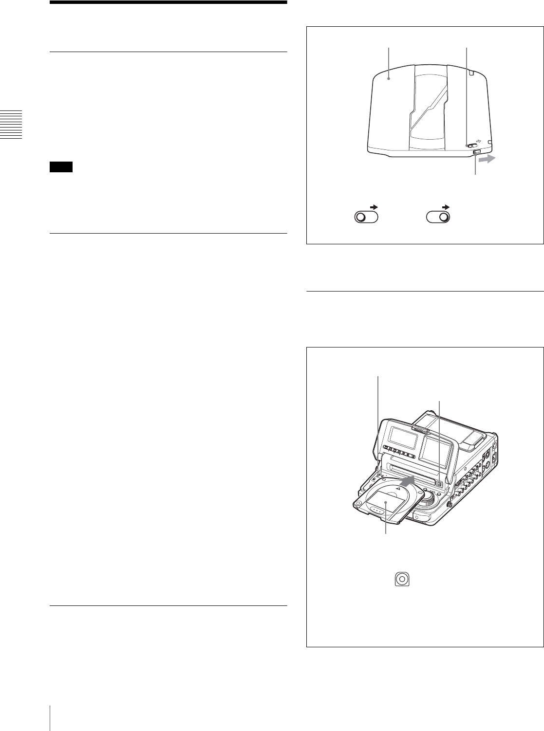
Chapter 3 Preparations
38 3-6 Handling Discs
3-6Handling Discs
3-6-1 Discs Used for Recording and
Playback
This disc recorder uses the following disc for recording
and playback: PFD23 Professional Disc 1) (capacity 23.3
GB)
1) Professional Disc is a trademark of Sony Corporation.
Note
It is not possible to use the following discs for recording or
playback:
•Blu-ray Disc
• Professional Disc for Data
3-6-2 Notes on Handling
Handling
The Professional Disc is housed in a cartridge, and is
designed to allow handling free of risk from dust or
fingerprints. However, if the cartridge is subjected to a
severe shock, for example by dropping it, this can result in
damage or scratching of the disc. If the disc is scratched, it
may be impossible to record video/audio, or to play back
the content recorded on the disc. The discs should be
handled and stored carefully.
• Do not touch the surface of the disc itself within the
cartridge.
• Deliberately opening the shutter may cause damage.
• Do not disassemble the cartridge.
• The supplied adhesive labels are recommended for
indexing discs. Apply the label in the correct position.
Storage
• Do not store discs where they may be subjected to direct
sunlight, or in other places where the temperature or
humidity is high.
• Do not leave cartridges where dust may be able to gain
ingress.
• Store cartridges in their cases.
Care of the discs
• Remove dust and dirt on the outside of a cartridge using
a soft dry cloth.
• If condensation forms, allow ample time to dry before
use.
3-6-3 Write-Protecting Discs
To protect the content recorded on the disc from accidental
erasure, move the Write Inhibit tab on the lower surface of
the disc in the direction of the arrow, as shown in the
following figure.
You can lock individual clips to prevent them from being
deleted. For details, see “Locking clips” (page 55).
3-6-4 Loading and Unloading a Disc
When the on/standby switch indicator is lit green, you can
load and unload a disc as shown in the following figure.
SAVE
SAVE SAVE
Lower surface of the disc Write Inhibit tab
Slide in the direction of the arrow
Write Inhibit tab settings
Recording enabled Recording disabled
SDI
To unload
Press the EJECT button.
To load
Insert a disc face up.
The disc is drawn in.
On/standby switch and
indicator
The disc loaded mark (see page 19) flashes while the
disc is being inserted, and while it is being ejected. Lights
when loading finishes, and goes out when eject finishes.
Recording stops and the disc is ejected if you press the
EJECT button during recording. If you do not want recording
to stop with the EJECT button, set extended menu item 145
“MODE KEY ENABLE DURING RECORDING” to “stop.”
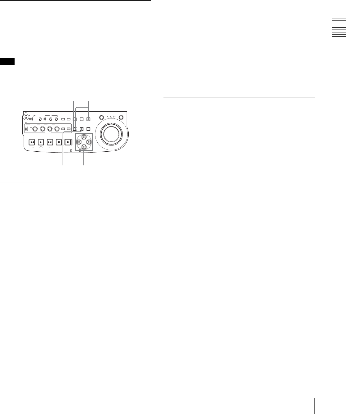
Chapter 3 Preparations
39
3-6 Handling Discs
If message “HUMID!” appears in the time data
display
There is moisture condensation in the unit.
For the steps to take when the message appears, see 8-2
“Condensation” (page 121).
3-6-5 Formatting a Disc
An unused disc requires no formatting operation. The disc
is automatically formatted when loaded into this unit.
To format a recorded disc, load the disc into the unit, then
proceed as follows.
Note
When a recorded disc is formatted, all the data on the disc
is erased. (Locked clips (see page 55) are also erased.)
1
Holding down the SHIFT button, press the MENU
button.
The system menu appears on the monitor screen.
2
Select “DISC MENU” using the F button or f button,
then press the g button.
The menu item “FORMAT” is displayed.
3
Select “FORMAT” using the F button or f button,
then press the g button.
The menu item “QUICK FORMAT” is selected.
4
Press the g button.
The message “QUICK FORMAT OK?” appears.
To return to the previous menu page without
formatting the disc
Press the RESET button.
5
Press the SET button.
Formatting is completed and the message “FORMAT
COMPLETED.” appears.
6
Press the MENU button.
This exits the menu.
To format several discs in succession
1
Carry out steps 1 to 5 in the previous procedure, and
then press the EJECT button to eject the disc.
2
Insert the next disc that you want to format.
The message “QUICK FORMAT OK?” appears.
3
Press the SET button.
4
When the message “FORMAT COMPLETED.”
appears, press the EJECT button to eject the disc.
5
Repeat steps 2 to 4 for all of the discs that you want to
format.
3-6-6 To Eject Discs With the Unit
Powered Off
When battery power is low and at other times, it may not
be possible to eject discs by pressing the EJECT button. In
these situations, you can use the following as an
emergency procedure to eject a disc manually.
1
Power the unit off.
2
Open the rubber cover and, using a Phillips
screwdriver, rotate the red screw in the
counterclockwise direction.
ACCESS
SHUTTLE JOG
THUMB
NAIL
ESSENCE
MARK
MENU
S.SEL
SET RESET
SHIFT
TOP F REV
ALL/CH-1 CH-2 CH-3 CH-4
TC
F FWD
AUDI O
END
REC
PRESET
VARIABLE
PB
PREV NEXTPLAY STOP REC
CLIP
MENU
SYSTEM
MENU
MONITOR
SEL
METER
SEL
HOLD
COUNTER
SEL
SUB
CLIP
MARK1
MARK2
IN OUT
KEY INHI
ON
OFF
NETWORK
LOCAL
REMOTE
F-RUN
R-RUN
PRESET
REGEN
INT
EXT
RP188
L/ST/R
2,3,45
16
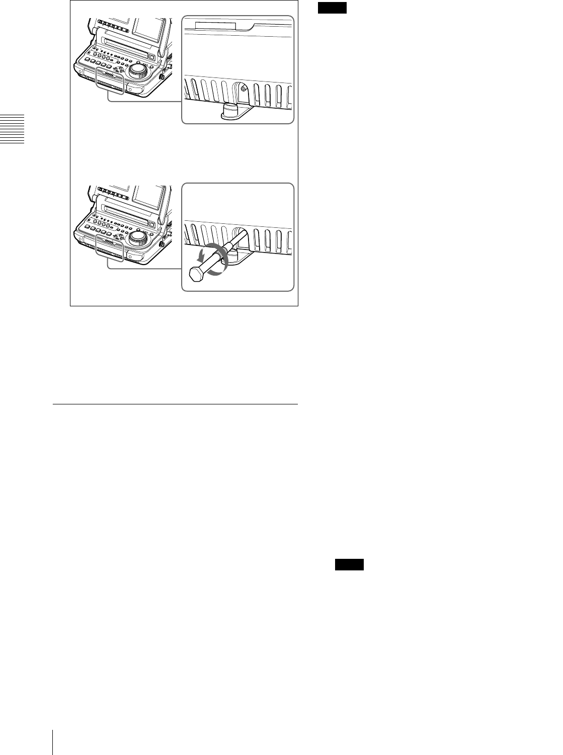
Chapter 3 Preparations
40 3-6 Handling Discs
The disc is ejected.
After removing the disc, you do not need to return the
screw to its original position. Normal operation will
resume when the unit is powered on again.
3
Close the rubber cover firmly.
3-6-7 Handling of Discs When
Recording Does Not End
Normally (Salvage Function)
Recording processing does not end normally when the
primary power 1) of this unit is lost during recording.
Because the file system is not updated, video and audio
data recorded in real time is not recognized as files and clip
contents recorded up to that point are lost.
However, this unit has a salvage function which can hold
losses to the minimum by reconstructing clips on such
discs.
Note that no recorded clip contents are lost when the on/
standby switch on the control panel is set to standby,
because the unit does not enter standby mode until after the
end of recording processing.
1) Primary power is lost when the AC power switch on the rear panel is
turned off, the AC power cord is disconnected, DC power is turned off, the
battery pack is exhausted, the battery pack is removed, and so on.
Notes
• Do not turn this unit’s primary power off until recording
processing has finished and the ACCESS indicator has
gone out.
• This function salvages as much recorded material as
possible after an unforeseen accident, but 100%
restoration cannot be guaranteed.
• Even when this function is used, it is not possible to
recover data from immediately before the interruption of
recording. The amount of data lost is as follows.
- Quick salvage: From 2 to 4 seconds of data before the
interruption of recording.
- Full salvage: From 4 to 6 seconds of data before the
interruption of recording.
Quick salvage
When the unit is powered on again after a recording
interruption due to power off, with the disc still loaded in
the unit, clips are reconstructed on the basis of backup data
stored in nonvolatile memory and markers recorded on the
disc.
Processing time is about 5 seconds.
Full salvage
When a disc that was manually ejected from a device
subjected to a recording interruption due to power off is
loaded into this unit, clips are reconstructed on the basis of
markers recorded on the disc. Nonvolatile memory cannot
be used, so processing takes longer than for a quick
salvage (about 30 seconds, although it depends on the state
of the disc).
Proceed as follows to perform a full salvage.
1
Insert the disc on which recording did not end
normally.
The message “Salvage ?” appears.
2
Do one of the following.
To salvage
Press the SET button.
Processing begins and the message “Executing.”
appears.
Notes
• If the REC INHI indicator (see page 18) is lit, the
message “EJECT?” appears. Eject the disc, set the
Write Inhibit tab to the recording enable position,
and insert the disc again.
• This operation cannot be cancelled once it begins.
The message “Complete” appears when processing
finishes. If the message reads “Incomplete!,” the clips
that failed were lost.

Chapter 3 Preparations
41
3-6 Handling Discs
To exit without salvaging
Press the RESET button.
The state of section where recording was interrupted is
saved, but no salvage processing is done.
Sections which were recorded normally can be played
back, but no new recording can be done on the disc. (A
quick format can be done on the disc, although all of
its contents will be lost.)
Note
Unless clips are salvaged, the message “Salvage ?”
appears again the next time the disc is inserted or the
unit is powered on.
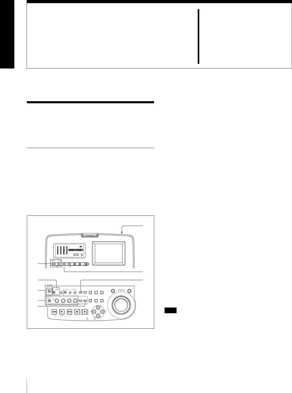
42 4-1 Recording
Chapter4
Recording/Playback
4-1Recording
This section describes video and audio recording on the
unit.
4-1-1 Preparations for Recording
Button/switch settings
Before beginning recording, make any necessary button/
switch settings.
For details of the settings of the buttons/switches, see the
pages indicated in parenthesis.
aAUDIO INPUT CH button (page 19) and AUDIO
INPUT SEL button (page 19)
Select the input audio signal.
bRemote control switch (page 12)
Set to LOCAL.
cOn/standby switch (page 12)
Indicator (`) lit green.
dVARIABLE switch (page 15) and ALL/CH-1, CH-
2 to CH-4 adjustment knobs (page 15)
Adjust the audio recording levels (page 43).
eAUDIO MONITOR SEL button (page 15)
Select the audio channels to monitor.
fAC power switch (rear panel) (page 11)
Set to the ` (on) position.
If you are using DC power or a battery pack, connect the
DC power or mount the battery pack on the battery pack
shoe before recording.
gVIDEO INPUT SEL button (page 19)
Select the input video signal.
hCOUNTER SEL button (page 13)
Select the data (elapsed recording time, time code value or
user bit data) to show in the time data display. When
displaying the time code value, select TC or VITC with
extended menu item 629 “TC SELECT.”
Setting the recording format
Before recording, it is necessary to set the recording format
for each of video and audio.
Note
It is not possible to combine different recording formats on
a single disc. When the format of previously recorded
sections on the disc does not match the current recording
format of this unit, the disc is record inhibited and the REC
INHI lights.
AUDIO VIDEO
INPUT SEL
WARNING KEY INHI REC INHI
INPUT CH INPUT SEL STATUS LIGHT MONITOR
HLOFFOFF ON
OFF ON
-30
dB
-12
-20
-40
-60
0
CH
- 15
DATA
OVER
-30
dB
-12
-20
-40
-60
0
CH-
26
DATA
OVER
-30
dB
-12
-20
-40
-60
0
CH-
37
DATA
OVER
-30
dB
-12
-20
-40
-60
0
CH-
48 BATT E F
DATA
OVER
VITC
HOURS MINUTES SECONDS FRAMES
COUNTER HOLDVIUB
PB EXT-LKNDF
DISC E B
ACCESS
SHUTTLE JOG
THUMB
NAIL
ESSENCE
MARK
MENU
S.SEL
SET RESET
SHIFT
TOP F REV
ALL/CH-1 CH-2 CH-3 CH-4
TC
F FWD
AUDI O
END
REC
PRESET
VARIABLE
PB
PREV NEXTPLAY STOP REC
CLIP
MENU
SYSTEM
MENU
MONITOR
SEL
METER
SEL
HOLD
COUNTER
SEL
SUB
CLIP
MARK1
MARK2
IN OUT
KEY INHI
ON
OFF
NETWORK
LOCAL
REMOTE
F-RUN
R-RUN
PRESET
REGEN
INT
EXT
RP188
L/ST/R
CHARACTER
VITC
PROCESS
CONTROL
1
2
3
4
5
6
7
8

Chapter 4 Recording/Playback
43
4-1 Recording
To set the video recording format
Use basic menu item 031 “RECORDING FORMAT” to
select the video recording format from MPEG IMX 50
Mbps, MPEG IMX 40 Mbps, MPEG IMX 30 Mbps, and
DVCAM.
The factory default setting is IMX50.
For details of the basic menu operations, see 7-2-2 “Basic
Menu Operations” on page 94.
To set the audio recording format
When using the MPEG IMX 50Mbps/40Mbps/30Mbps
for video: Use the maintenance menu item “AUDIO
CONFIG” to select 16 bits/8 channels or 24 bits/4
channels.
The factory default setting is 16 bits/8 channels.
When using the DVCAM format for video: Selection is
not necessary. The format of 16 bits/4 channels is
selected automatically.
For details of the maintenance menu operations, see 7-4-2
“Maintenance Menu Operations” on page 114.
File writing formats with FAM and FTP
connections
It is not necessary to set the video recording format
(IMX50/IMX40/IMX30/DVCAM) and the audio
recording format (16bit × 8ch/24bit × 4ch) before writing
files.
The file formats which can be written to the disc depend on
whether clips are already recorded on the disc.
When you insert a disc with no recorded clips: Files in
all of the above formats can be written.
When you insert a disc with recorded clips: Files in the
same video and audio formats as the clips on the disc
can be written.
Making thumbnail image settings
As required, you can select which frame to display as a
clip’s thumbnail image. (When the unit is shipped from the
factory, it is set up to display the first frame as the
thumbnail.)
For example, if all clips have the same image in their first
frames, you can specify a frame a few seconds after the
start of the clip, so that thumbnails will not all show the
same image.
To specify the frame to use as the thumbnail
image
Set extended menu item 143 “INDEX PICTURE
POSITION” to a number in the range from 0 to 10, in units
of 1 second.
See 7-3-2 “Extended Menu Operations” (page 108) for
more information about how to make extended menu
settings.
To adjust the audio recording levels
When carrying out audio recording at a reference
level
Set the VARIABLE switch (see page 15) to PRESET. The
audio signals will be recorded at a preset reference level.
Use the maintenance menu item “AUDIO CONFIG” to set
the audio input level and reference level.
For details of the maintenance menu operations, see 7-4-2
“Maintenance Menu Operations” on page 114.
Manually adjusting the audio recording
levels
Set the VARIABLE switch (see page 15) to REC and
adjust the ALL/CH-1 and CH-2 to CH-4 adjustment knobs
so that the audio level indications on the audio level meters
(see page 18) do not exceed 0 dB for a maximum volume.
Carry out the adjustment in E-E mode.
To select the E-E mode, see extended menu item 108
“AUTO EE SELECT.”
To adjust the audio recording levels for channels 1 to 8
simultaneously, set extended menu item 131 “AUDIO
VOLUME” to “all” and turn the ALL/CH-1 adjustment
knob.

Chapter 4 Recording/Playback
44 4-1 Recording
4-1-2 Recording Time Code and User Bit Values
There are the following four ways of recording time code:
• Internal Preset mode, which records the output of the
internal time code generator, set beforehand to an initial
value. The following run modes can be selected.
- Free Run: Time code advances continually.
- Rec Run: Time code advances only during recording.
• Internal Regen mode, which records the output of the
internal time code generator, initialized to time code
following continuously upon the time code of the last
frame of the last clip on the disc.
• External Regen mode, which records the output of the
internal time code generator, synchronized to an external
time code generator. As the external input, the time code
input to any of the following connectors can be selected.
- TIME CODE IN connector: LTC
- VIDEO IN connector: VITC
- S400 (i.LINK) connector: TC or VITC
- SDI IN connector: SMPTE RP188 LTC
• External Preset mode, which directly records the input of
an external time code generator. As the external input,
the time code input to any of the following connectors
can be selected.
- TIME CODE IN connector: TC
- S400 (i.LINK) connector: TC
- SDI IN connector: SMPTE RP188 LTC
As shown in the following table, you can switch between
different time code recording modes by combining switch
settings in the time data settings section with the selection
of a video input signal and settings of extended menu item
629.
To record time code after setting an initial
value
Set the following switches beforehand.
• INT/EXT/RP188 switch: INT
• PRESET/REGEN switch: PRESET
• F-RUN/R-RUN switch: F-RUN or R-RUN
See 7-3-2 “Extended Menu Operations” (page 108) for
more information about how to make extended menu
settings.
Then set an initial value as described below, and carry out
recording (see page 48).
To set an initial value
Proceed as follows.
Time code recording mode Time data settings section switch VIDEO INPUT
SEL button
Item
629
Reference
INT/EXT/
RP188
PRESET/
REGEN
F-RUN/
R-RUN
Internal Preset Free Run INT PRESET F-RUN – – “To record time code
after setting an initial
value” (page 44)
Internal Preset Rec Run R-RUN – –
Internal Regen INT REGEN – – – “To record time code
that follows sequentially
upon the last recorded
time code” (page 46)
External Regen (TC IN connector:
LTC) EXT REGEN – SDI/
COMPOSITE/
SG
tc “To record with the
internal time code
generator synchronized
to external time code”
(page 46)
External Regen (VIDEO IN
connector: VITC) vitc
External Regen (i.LINK connector:
TC) i.LINK tc
External Regen (i.LINK connector:
VITC) vitc
External Regen (SDI IN
connector: SMPTE RP188 LTC) RP188 REGEN – SDI –
External Preset (TC IN connector:
TC) EXT PRESET – SDI/
COMPOSITE/
SG
– “To record external time
code directly” (page 47)
External Preset (i.LINK connector:
TC) i.LINK –
External Preset (SDI IN
connector: SMPTE RP188 LTC) RP188 PRESET – SDI –
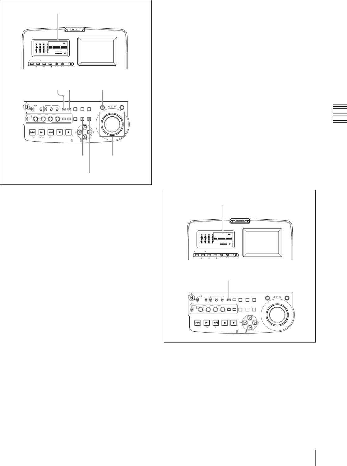
Chapter 4 Recording/Playback
45
4-1 Recording
1
Watching the indicators above the time data display,
press the COUNTER SEL button to select TC.
2
Press the HOLD button.
The SHUTTLE button lights and the first two digits of
the time code shown in the time data display start
flashing.
To set all digits to 0
Press the RESET button.
3
Select the digits to set by rotating the shuttle dial or jog
dial.
The flashing digits change to the next two digits on the
right when you rotate the shuttle dial or jog dial
clockwise, and to the next two digits on the left when
you rotate it counterclockwise.
4
Set the value for the flashing digits by rotating the
shuttle dial or jog dial while holding the SHUTTLE
button.
5
Repeat steps 3 and 4 until you finish setting all digits.
6
Press the SET button.
• An initial time code value is set and the monitor
returns to the time code display before the HOLD
button was pressed in step 2.
• If the F-RUN/R-RUN switch is set to F-RUN, the
time code starts advancing from the initial value
immediately.
To set time code to the time of the internal clock
You can record time code synchronized to the time of the
internal clock.
To do so, set the INT/EXT/RP188 switch to INT, set the
PRESET/REGEN switch to PRESET, and then proceed as
follows.
1
Carry out steps 1 and 2 of the previous section, “To
record time code after setting an initial value.”
2
With the SHUTTLE button held down, rotate the jog
dial in the counterclockwise direction. Stop rotating
when “CLOCK” appears in the time data display and
the video panel.
3
Press the SET button.
To set user bits
You can record up to eight hexadecimal digits of
information (date, time, clip name, etc.) in the time code
track.
Proceed as follows.
1
Watching the indicators above the time data display,
press the COUNTER SEL button to select UB.
2
Carry out steps 2 to 6 of the section “To set an initial
value” (page 44).
Settings are made in hexadecimal (0, 1, 2,... 8, 9, A,
B,... E, F).
AUDIO VIDEO
INPUT SEL
WARNING KEY INHI REC INHI
INPUT CH INPUT SEL STATUS LIGHT MONITOR
HLOFFOFF ON
OFF ON
-30
dB
-12
-20
-40
-60
0
CH
- 15
DATA
OVER
-30
dB
-12
-20
-40
-60
0
CH-
26
DATA
OVER
-30
dB
-12
-20
-40
-60
0
CH-
37
DATA
OVER
-30
dB
-12
-20
-40
-60
0
CH-
48 BATT E F
DATA
OVER
VITC
HOURS MINUTES SECONDS FRAMES
COUNTER HOLDVIUB
PB EXT-LKNDF
DISC E B
ACCESS
SHUTTLE JOG
THUMB
NAIL
ESSENCE
MARK
MENU
S.SEL
SET RESET
SHIFT
TOP F REV
ALL/CH-1 CH-2 CH-3 CH-4
TC
F FWD
AUDI O
END
REC
PRESET
VARIABLE
PB
PREV NEXTPLAY STOP REC
CLIP
MENU
SYSTEM
MENU
MONITOR
SEL
METER
SEL
HOLD
COUNTER
SEL
SUB
CLIP
MARK1
MARK2
IN OUT
KEY INHI
ON
OFF
NETWORK
LOCAL
REMOTE
F-RUN
R-RUN
PRESET
REGEN
INT
EXT
RP188
L/ST/R
CHARACTER
VITC
PROCESS
CONTROL
3,46
12 4
Time data display
SHUTTLE button
RESET button
AUDIO VIDEO
INPUT SEL
WARNING KEY INHI REC INHI
INPUT CH INPUT SEL STATUS LIGHT MONITOR
HLOFFOFF ON
OFF ON
-30
dB
-12
-20
-40
-60
0
CH
- 15
DATA
OVER
-30
dB
-12
-20
-40
-60
0
CH-
26
DATA
OVER
-30
dB
-12
-20
-40
-60
0
CH-
37
DATA
OVER
-30
dB
-12
-20
-40
-60
0
CH-
48 BATT E F
DATA
OVER
VITC
HOURS MINUTES SECONDS FRAMES
COUNTER HOLDVIUB
PB EXT-LKNDF
DISC E B
ACCESS
SHUTTLE JOG
THUMB
NAIL
ESSENCE
MARK
MENU
S.SEL
SET RESET
SHIFT
TOP F REV
ALL/CH-1 CH-2 CH-3 CH-4
TC
F FWD
AUDI O
END
REC
PRESET
VARIABLE
PB
PREV NEXTPLAY STOP REC
CLIP
MENU
SYSTEM
MENU
MONITOR
SEL
METER
SEL
HOLD
COUNTER
SEL
SUB
CLIP
MARK1
MARK2
IN OUT
KEY INHI
ON
OFF
NETWORK
LOCAL
REMOTE
F-RUN
R-RUN
PRESET
REGEN
INT
EXT
RP188
L/ST/R
CHARACTER
VITC
PROCESS
CONTROL
1
Time data display
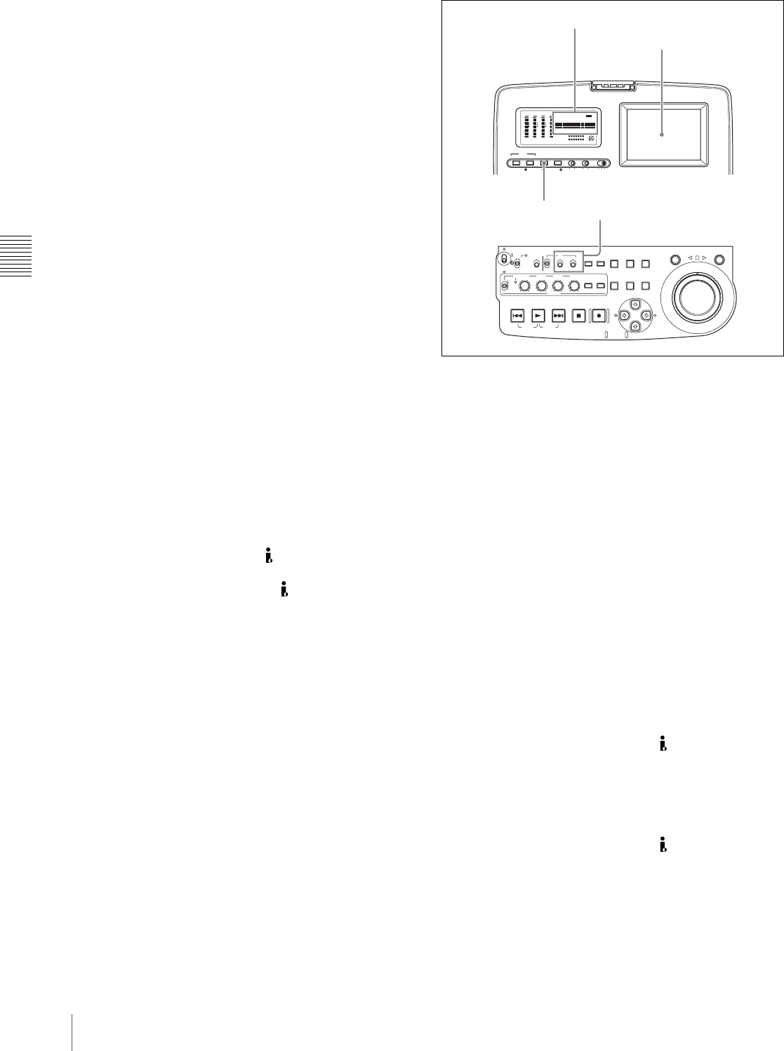
Chapter 4 Recording/Playback
46 4-1 Recording
To record time code that follows
sequentially upon the last recorded time
code
You can record time code so that it is continuous from one
clip to the next on the disc.
Set the INT/EXT/RP188 switch to INT and the PRESET/
REGEN switch to REGEN beforehand. When this setting
is in force, the unit reads the time code of the last frame of
the last recorded clip on the disc before starting to record,
and internally generates time code that follows upon the
recorded time code.
In this case, the setting of extended menu item 628 “DF
MODE” is ignored. New time code is recorded in the drop-
frame mode of the last recorded time code on the disc.
To record with the internal time code
generator synchronized to external time
code
You can record with the internal time code generator
synchronized to time code input from an external device.
Use this method to synchronize the time code generators of
a number of recorders, or to carry out recording
maintaining the synchronization between the source video
and time code.
In this case, the settings of the F-RUN/R-RUN switch and
extended menu item 628 “DF MODE” are ignored.
You can synchronize the internal time code generator to
one of the following external time codes.
• TC input to this unit’s TC IN connector
• VITC in a video signal input to this unit
• SMPTE RP188 LTC in an SDI signal input to this unit
• i.LINK TC input to this unit’s S400 (i.LINK)
connector
• i.LINK VITC input to this unit’s S400 (i.LINK)
connector
Use the following procedure to synchronize the internal
time code generator according to the type of external time
code.
1
Make either of the following connections and settings.
To synchronize to time code input to the TC IN
connector
Connect the time code output from the external device
to the TC IN connector. Press the VIDEO INPUT SEL
button and, while viewing the time data display or the
video panel, select one of SDI, COMPOSITE, or SG.
To synchronize to VITC in an input video signal
Connect a video signal containing VITC to the VIDEO
IN connector or the SDI IN connector. Press the
VIDEO INPUT SEL button and, while viewing the
time data display or the video panel, select
COMPOSITE or SDI.
To synchronize to SMPTE RP188 LTC in an SDI
signal
Connect an SDI signal containing SMPTE RP188
LTC to the SDI IN connector.
To synchronize to i.LINK TC
Connect an i.LINK signal to the S400 (i.LINK)
connector. Press the VIDEO INPUT SEL button and,
while viewing the time data display or the video panel,
select i.LINK.
To synchronize to i.LINK VITC
Connect an i.LINK signal to the S400 (i.LINK)
connector. Press the VIDEO INPUT SEL button and,
while viewing the time data display or the video panel,
select i.LINK.
2
Make the following settings.
AUDIO VIDEO
INPUT SEL
WARNING KEY INHI REC INHI
INPUT CH INPUT SEL STATUS LIGHT MONITOR
HLOFFOFF ON
OFF ON
-30
dB
-12
-20
-40
-60
0
CH
- 15
DATA
OVER
-30
dB
-12
-20
-40
-60
0
CH-
26
DATA
OVER
-30
dB
-12
-20
-40
-60
0
CH-
37
DATA
OVER
-30
dB
-12
-20
-40
-60
0
CH-
48 BATT E F
DATA
OVER
VITC
HOURS MINUTES SECONDS FRAMES
COUNTER HOLDVIUB
PB EXT-LKNDF
DISC E B
ACCESS
SHUTTLE JOG
THUMB
NAIL
ESSENCE
MARK
MENU
S.SEL
SET RESET
SHIFT
TOP F REV
ALL/CH-1 CH-2 CH-3 CH-4
TC
F FWD
AUDI O
END
REC
PRESET
VARIABLE
PB
PREV NEXTPLAY STOP REC
CLIP
MENU
SYSTEM
MENU
MONITOR
SEL
METER
SEL
HOLD
COUNTER
SEL
SUB
CLIP
MARK1
MARK2
IN OUT
KEY INHI
ON
OFF
NETWORK
LOCAL
REMOTE
F-RUN
R-RUN
PRESET
REGEN
INT
EXT
RP188
L/ST/R
CHARACTER
VITC
PROCESS
CONTROL
12
Time data display
Video panel
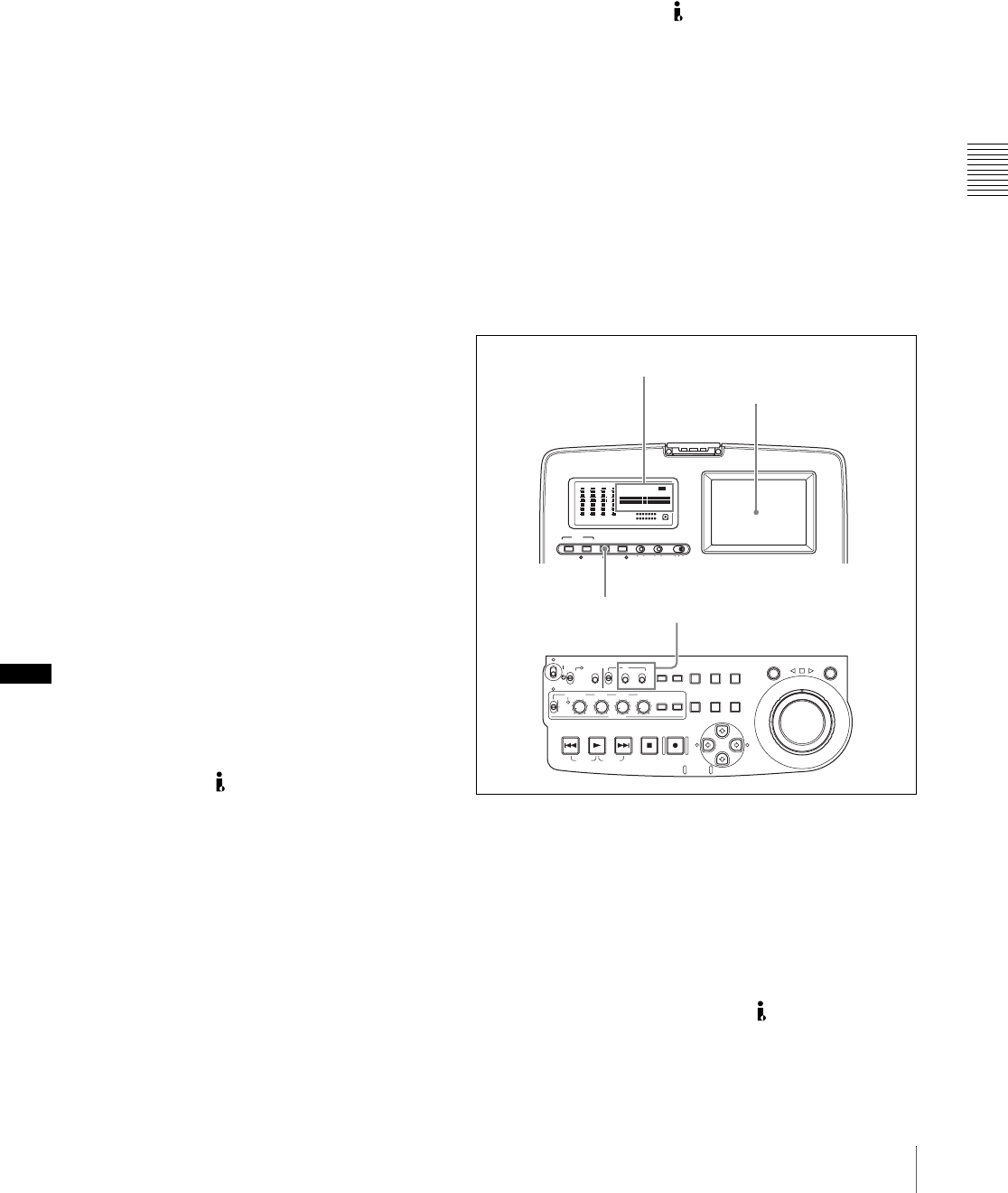
Chapter 4 Recording/Playback
47
4-1 Recording
To synchronize to time code input to the TC IN
connector
• Set the INT/EXT/RP188 switch to EXT and the
PRESET/REGEN switch to REGEN.
• Set extended menu item 629 “TC SELECT” to “tc.”
To synchronize to VITC in an input video signal
• Set the INT/EXT/RP188 switch to EXT and the
PRESET/REGEN switch to REGEN.
• Set extended menu item 629 “TC SELECT” to
“vitc.”
To synchronize to SMPTE RP188 LTC in an SDI
signal
Set the INT/EXT/RP188 switch to RP188 and the
PRESET/REGEN switch to REGEN.
To synchronize to i.LINK TC
• Set the INT/EXT/RP188 switch to EXT and the
PRESET/REGEN switch to REGEN.
• Set extended menu item 629 “TC SELECT” to “tc.”
To synchronize to i.LINK VITC
• Set the INT/EXT/RP188 switch to EXT and the
PRESET/REGEN switch to REGEN.
• Set extended menu item 629 “TC SELECT” to
“vitc.”
For details of menu setting operations, see Chapter 7
“Menus” on page 89.
This starts the internal time code generator running in
synchronization with the external time code generator.
Once the internal time code generator is synchronized
with the external time code generator, even if the
external time code generator connection is removed,
the internal time code generator continues to run.
Notes
• When the input video signal selected is i.LINK or SDI,
setting the INT/EXT/RP188 switch to EXT and the
PRESET/REGEN switch to REGEN automatically
synchronizes the internal time code generator to the time
code received through the S400 (i.LINK) connector or
SDI IN connector.
• When the INT/EXT/RP188 switch is set to EXT and the
PRESET/REGEN switch is set to REGEN, the internal
time code advance mode and frame count mode (for 525
line mode only) are automatically set as follows.
Advance mode: free running
Frame count mode (for 525 line mode only): the same
as the external time code signal (drop frame or non-
drop frame)
To check the synchronization to the external
signal
Press the STOP button to stop this unit, then press the REC
button.
Check that the time code value shown in the time data
display coincides with the external time code value.
To record external time code directly
You can record both of the following types of external time
code directly.
• TC input to the TC IN connector of this unit
• i.LINK TC input to the S400 (i.LINK) connector of
this unit
• SMPTE RP-188 LTC in an SDI signal input to the SDI
IN connector of this unit
When you use this method, the internal time code
generator advances without being affected by the external
time code.
To record the playback time code of external VTRs, the
methods described above in “To record with the internal
time code generator synchronized to external time code”
are recommended.
Use the following procedure to record external time code
directly, according to the type of external time code.
1
Make either of the following connections and settings.
To directly record TC input to the TC IN connector
Connect the time code output from the external device
to the TC IN connector. Press the VIDEO INPUT SEL
button and, while viewing the time data display or the
video panel, select one of SDI, COMPOSITE, or SG.
To directly record i.LINK TC
Connect an i.LINK signal to the S400 (i.LINK)
connector. Press the VIDEO INPUT SEL button and,
while viewing the time data display or the video panel,
select i.LINK.
AUDIO VIDEO
INPUT SEL
WARNING KEY INHI REC INHI
INPUT CH INPUT SEL STATUS LIGHT MONITOR
HLOFFOFF ON
OFF ON
-30
dB
-12
-20
-40
-60
0
CH
- 15
DATA
OVER
-30
dB
-12
-20
-40
-60
0
CH-
26
DATA
OVER
-30
dB
-12
-20
-40
-60
0
CH-
37
DATA
OVER
-30
dB
-12
-20
-40
-60
0
CH-
48 BATT E F
DATA
OVER
VITC
HOURS MINUTES SECONDS FRAMES
COUNTER HOLDVIUB
PB EXT-LKNDF
DISC E B
ACCESS
SHUTTLE JOG
THUMB
NAIL
ESSENCE
MARK
MENU
S.SEL
SET RESET
SHIFT
TOP F REV
ALL/CH-1 CH-2 CH-3 CH-4
TC
F FWD
AUDI O
END
REC
PRESET
VARIABLE
PB
PREV NEXTPLAY STOP REC
CLIP
MENU
SYSTEM
MENU
MONITOR
SEL
METER
SEL
HOLD
COUNTER
SEL
SUB
CLIP
MARK1
MARK2
IN OUT
KEY INHI
ON
OFF
NETWORK
LOCAL
REMOTE
F-RUN
R-RUN
PRESET
REGEN
INT
EXT
RP188
L/ST/R
CHARACTER
VITC
PROCESS
CONTROL
12
Time data display
Video panel
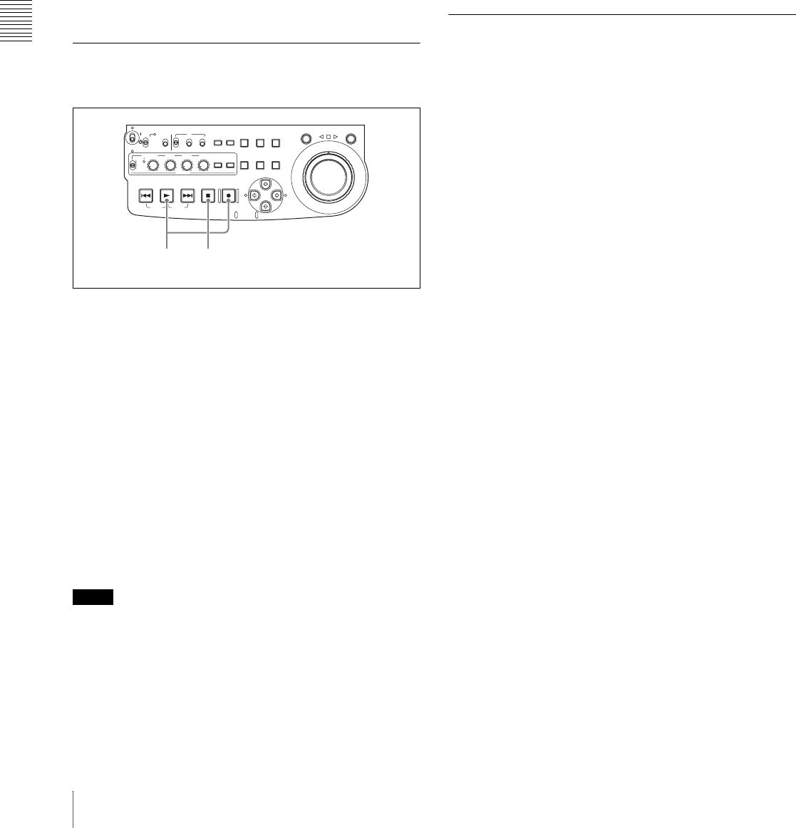
Chapter 4 Recording/Playback
48 4-1 Recording
To directly record SMPTE RP-188 LTC in an SDI
signal
Connect an SDI signal containing SMPTE RP188
LTC to the SDI IN connector. Press the VIDEO
INPUT SEL button and, while viewing the time data
display or the video panel, select SDI.
2
Set the PRESET/REGEN switch to PRESET, and set
the INT/EXT/RP188 to one of the following.
To record TC input to the TC IN connector, or
i.LINK TC: EXT
To record SMPTE RP188 LTC: RP188
For details of menu setting operations, see Chapter 7
“Menus” (page 89).
4-1-3 Recording Operation
To record, proceed as follows.
1
Insert a disc.
For details, see 3-6-4 “Loading and Unloading a
Disc” on page 38.
2
Hold down the REC button, and press the PLAY
button.
Recording starts.
3
To stop recording, press the STOP button.
If the disc becomes full
Recording stops and the message “ALARM DISC END.”
appears on the video panel.
Notes
• The shortest clip that can be recorded is 2 seconds long.
Even if recording start and stop operations are performed
within 2 seconds, a 2-second clip is recorded.
• The maximum number of clips that can be recorded is
300. If the loaded disc already contains 300 clips,
recording with the REC button is not possible. (The
message “Disc Full!” appears in the time data display.)
• Do not allow the unit’s primary power to be lost during
recording. 1) This could cause the clip being recorded to
be lost. (See 3-6-7 “Handling of Discs When Recording
Does Not End Normally (Salvage Function)” on page
40.)
1) Primary power is lost when the AC power switch on the rear panel is
turned off, the AC power cord is disconnected, DC power is turned off, the
battery pack is exhausted, the battery pack is removed, and so on.
To record essence marks
A shot mark 1 essence mark or shot mark 2 essence mark
is recorded if you hold down the F/MARK1 or f/MARK2
button and press the SET button during recording.
4-1-4 Auto Clip List Recording for
Automatic Inclusion of
Recorded Clips in Clip Lists
Auto clip list recording is a function for automatically
including the clips generated by recording operations in a
selected clip list. The updated clip list is saved to the disc.
Proceed as follows.
1
Insert a disc.
2
Load a clip list from the disc.
• To create a new clip list, load a NEW FILE (empty)
clip list.
• To add clips to an existing clip list, load that clip list.
For operations, see 5-3-1 “Loading a Clip List From
Disc Into Unit Memory” (page 68).
3
Press the SUBCLIP button, turning it on.
The unit enters auto clip list recording mode, and the
number of the clip list which is loaded in the current
clip list appears.
4
Press the REC button to start recording.
A clip is generated automatically from the video and
audio recorded in the interval from start to stop of
recording, and added as a sub clip to the current clip
list. When recording stops, the updated clip list is
written to disc.
5
Repeat the process of recording and stopping until you
have included all the required clips.
To change the registered clip list, repeat step 2 to load
the desired clip list.
To exit auto clip list recording mode
Press the SUBCLIP button, turning it off.
ACCESS
SHUTTLE JOG
THUMB
NAIL
ESSENCE
MARK
MENU
S.SEL
SET RESET
SHIFT
TOP F REV
ALL/CH-1 CH-2 CH-3 CH-4
TC
F FWD
AUDI O
END
REC
PRESET
VARIABLE
PB
PREV NEXTPLAY STOP REC
CLIP
MENU
SYSTEM
MENU
MONITOR
SEL
METER
SEL
HOLD
COUNTER
SEL
SUB
CLIP
MARK1
MARK2
IN OUT
KEY INHI
ON
OFF
NETWORK
LOCAL
REMOTE
F-RUN
R-RUN
PRESET
REGEN
INT
EXT
RP188
L/ST/R
2 3

Chapter 4 Recording/Playback
49
4-2 Playback
4-2Playback
This section describes playback of video and audio.
Disc playback start position
Although this unit uses optical discs, it is designed to offer
the most convenient features of tape playback by VTRs.
One of these is the playback start position, which works in
the same way as tape, as described below.
After playback stop
The unit stops at the position where the STOP button was
pressed.
Press the PLAY button to resume playback at the stop
position.
After recording
The unit stops at the position where recording ended.
To play back a clip, press the PREV button to move to the
start frame of any clip, or press the PREV button with the
PLAY button held down to move to any position.
After disc insertion
The unit stops at the position of the disc when it was most
recently ejected.
Press the PLAY button to resume playback at the most
recent position.
The playback position is saved to the disc when the disc is
ejected, which allows playback to start at that position
whenever it is loaded into any XDCAM player.
Note
This function is not available when the Write Inhibit tab of
the disc is set to the recording disabled position, and when
extended menu item 310 “REC INHIBIT” is set to “on.”
The REC INHI indicator may light when neither of the
above are true if the format of recorded sections on the disc
is not the same as the recording settings of this unit. In this
case, the playback position can be saved to the disc.
4-2-1 Preparations for Playback
Button/switch settings
Before beginning playback, make any necessary button/
switch settings.
For details of the settings of the buttons/switches, see the
pages indicated in parenthesis.
aRemote control switch (page 12)
Set to LOCAL.
bOn/standby switch (page 12)
Indicator (`) lit green.
cVARIABLE switch (page 15) and ALL/CH-1, CH-
2 to CH-4 adjustment knobs (page 15)
Adjust the audio playback levels.
dAUDIO MONITOR SEL button (page 15)
Select the audio channels to monitor.
eAC power switch (rear panel) (page 11)
Set to the ` (on) position.
If you are using DC power or a battery pack, connect the
DC power or mount the battery pack on the battery pack
shoe before playback.
fCOUNTER SEL button (page 13)
Select the data (elapsed playback time, time code value or
user bit data) to be displayed in the time data display.
When displaying the time code value, select TC or VITC
with extended menu item 629 “TC SELECT.”
Adjusting video processing parameters
You can adjust the following video processing parameters.
• Video output level
• Chroma output level
• Setup/black level
• Chroma phase
• Output signal sync phase
• Output signal subcarrier phase
AUDIO VIDEO
INPUT SEL
WARNING KEY INHI REC INHI
INPUT CH INPUT SEL STATUS LIGHT MONITOR
HLOFFOFF ON
OFF ON
-30
dB
-12
-20
-40
-60
0
CH
- 15
DATA
OVER
-30
dB
-12
-20
-40
-60
0
CH-
26
DATA
OVER
-30
dB
-12
-20
-40
-60
0
CH-
37
DATA
OVER
-30
dB
-12
-20
-40
-60
0
CH-
48 BATT E F
DATA
OVER
VITC
HOURS MINUTES SECONDS FRAMES
COUNTER HOLDVIUB
PB EXT-LKNDF
DISC E B
ACCESS
SHUTTLE JOG
THUMB
NAIL
ESSENCE
MARK
MENU
S.SEL
SET RESET
SHIFT
TOP F REV
ALL/CH-1 CH-2 CH-3 CH-4
TC
F FWD
AUDI O
END
REC
PRESET
VARIABLE
PB
PREV NEXTPLAY STOP REC
CLIP
MENU
SYSTEM
MENU
MONITOR
SEL
METER
SEL
HOLD
COUNTER
SEL
SUB
CLIP
MARK1
MARK2
IN OUT
KEY INHI
ON
OFF
NETWORK
LOCAL
REMOTE
F-RUN
R-RUN
PRESET
REGEN
INT
EXT
RP188
L/ST/R
CHARACTER
VITC
PROCESS
CONTROL
1
2
3
4
5
6
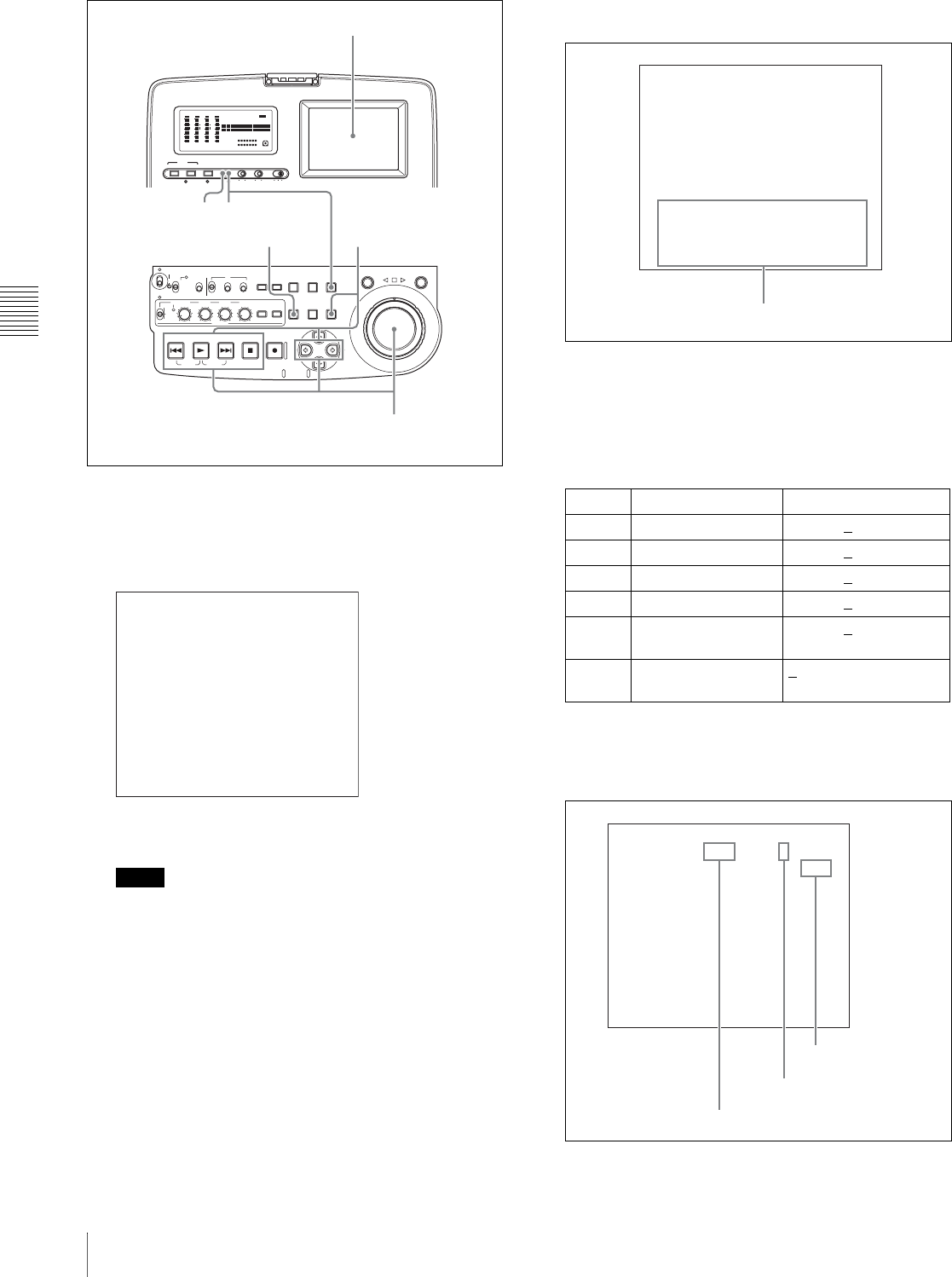
Chapter 4 Recording/Playback
50 4-2 Playback
1
With the SHIFT button held down, press the STATUS
button.
The process control screen 1) appears in the video
panel.
1) When the line mode is 525(U)/525(J), SETUP appears instead of
BLACK.
Notes
• Do the following operations within 30 seconds. The
screen returns to the normal screen if no operation is
done for 30 seconds.
• The process control screen does not appear if either
of the following is true.
- The unit is being controlled from a device
connected to the REMOTE connector, and basic
menu item 006 “LOCAL FUNCTION ENABLE”
is set to “dis” or “st&ej.”
- The unit is connected to a computer by FAM or
FTP, and the computer is logged in to this unit.
To check the assignments to buttons which
select parameters
A list of button assignments appears at the bottom of
the screen when you keep the MENU button pressed.
2
Hold down the following buttons and press the RESET
button to select “PRE” (PRESET: factory preset
setting) or “VAR” (VARIABLE: adjustable setting).
Each press of the button switches between “PRE” and
“VAR.”
a) Underlined values are the factory defaults.
The figure below is an example of the screen that
appears when you hold the PLAY button down.
AUDIO VIDEO
INPUT SEL
WARNING KEY INHI REC INHI
INPUT CH INPUT SEL STATUS LIGHT MONITOR
HLOFFOFF ON
OFF ON
-30
dB
-12
-20
-40
-60
0
CH
- 15
DATA
OVER
-30
dB
-12
-20
-40
-60
0
CH-
26
DATA
OVER
-30
dB
-12
-20
-40
-60
0
CH-
37
DATA
OVER
-30
dB
-12
-20
-40
-60
0
CH-
48 BATT E F
DATA
OVER
VITC
HOURS MINUTES SECONDS FRAMES
COUNTER HOLDVIUB
PB EXT-LKNDF
DISC E B
ACCESS
SHUTTLE JOG
THUMB
NAIL
ESSENCE
MARK
MENU
S.SEL
SET RESET
SHIFT
TOP F REV
ALL/CH-1 CH-2 CH-3 CH-4
TC
F FWD
AUDI O
END
REC
PRESET
VARIABLE
PB
PREV NEXTPLAY STOP REC
CLIP
MENU
SYSTEM
MENU
MONITOR
SEL
METER
SEL
HOLD
COUNTER
SEL
SUB
CLIP
MARK1
MARK2
IN OUT
KEY INHI
ON
OFF
NETWORK
LOCAL
REMOTE
F-RUN
R-RUN
PRESET
REGEN
INT
EXT
RP188
L/ST/R
CHARACTER
VITC
PROCESS
CONTROL
3
4
15 MENU button
Video panel
VIDEO VAR ----- -----
CHROMA-Ph PRE ----- -----
SYNC-Ph PRE ----- -----
CHROMA VAR ----- -----
BLACK PRE ----- -----
SC-Ph PRE 000
PROCESS CONTROL V
-----
KEY ASIGN : MENU
ADJUST : KEY+JOG DIAL
PREST/VAR : KEY+RESET
EXIT : STATUS
Button Parameter Adjustment range a)
PREV Video output level –512 to 0 to 511
PLAY Chroma output level –512 to 0 to 511
NEXT Setup/black level –512 to 0 to 511
STOP Chroma phase –128 to 0 to 127
GOutput signal sync
phase –128 to 0 to 127
gOutput signal
subcarrier phase 0 to 511
VIDEO VAR ----- -----
CHROMA-Ph PRE ----- -----
SYNC-Ph PRE ----- -----
CHROMA VAR ----- -----
BLACK PRE ----- -----
SC-Ph PRE 000
PROCESS CONTROL V
-----
PREV:VIDEO (<):SYS-Ph
PLAY:CHROMA (>):SC-Ph
NEXT:SETUP or BLACK
STOP:CHROMA-ph
List of parameters assigned to buttons
CHROMA PRE ----- -----
000
PROCESS CONTROL V
-
Select “PRE” or “VAR”
Marker indicating the
position of the setting in
the adjustment range
Setting
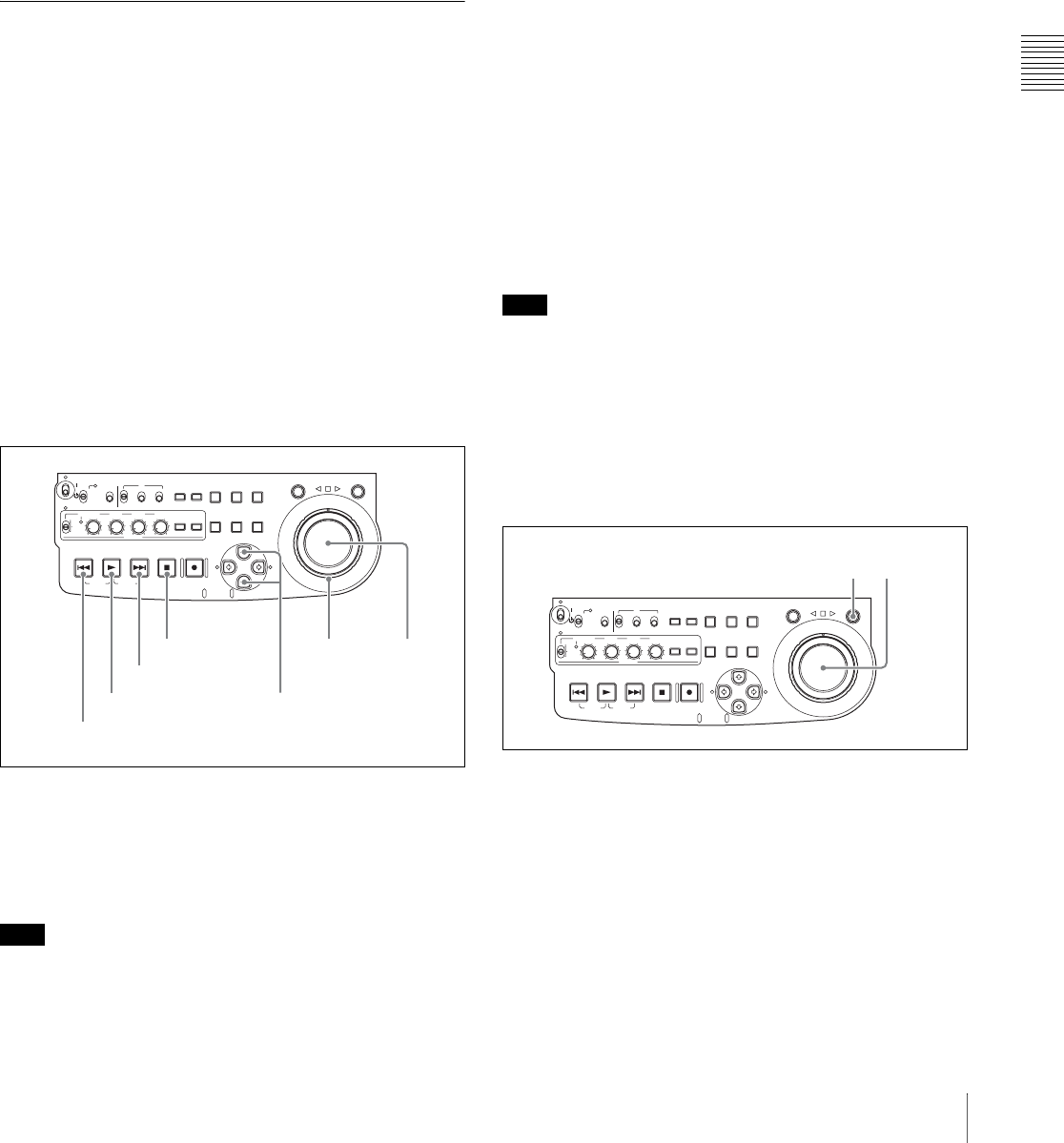
Chapter 4 Recording/Playback
51
4-2 Playback
3
If you selected “VAR” in step 2, set the parameter
value by holding down the corresponding button and
rotating the jog dial, while viewing the video.
Setting values vary with the rotation speed of the jog
dial.
4
Repeat steps 2 and 3 as required to set other
parameters.
5
Press the STATUS button to return to the normal
screen.
4-2-2 Playback Operation
This section describes the following types of playback:
• Normal playback
Playback at normal (±1) speed
• Playback in jog mode
Variable speed playback, with the speed determined by
the speed of turning the jog dial
• Playback in shuttle mode
Variable speed playback, with the speed determined by
the angular position of the shuttle dial
Normal playback
First insert a disc.
For details of how to insert a disc, see 3-6-4 “Loading and
Unloading a Disc” on page 38.
To start playback
Press the PLAY button.
Playback starts.
When two or more clips are recorded on the disc, they are
played back continuously.
Note
No audio is output when non-audio signals are played
back.
To jump to the next or previous clip, then start
playback
Use the PREV button, NEXT button, jog dial, or shuttle
dial.
For information about the functions of these buttons, see
“5 Recording and playback control section” on page 16.
For details of the jog and shuttle dials, see “3 Jog/shuttle
control block” on page 14.
To stop playback
Press the STOP button.
If you play back to the end of the last clip
Playback automatically stops.
If, in this state, you press the PLAY button, the message
“ALARM DISC END.” appears on the monitor.
To carry out playback again, move back to the desired clip
using the PREV button, jog dial or shuttle dial.
To record an essence mark
While playing back a disc, you can record essence marks
such as shot mark 1 and shot mark 2 in desired frames.
To record a shot mark 1 or shot mark 2, hold down the F/
MARK1 or f/MARK2 button and press the SET button.
Note
To erase or change essence marks, use the supplied
PDZ-1 Proxy Browsing Software.
Playback in jog mode
In jog mode, you can control the speed of playback by the
speed of turning the jog dial. The playback speed range is
±1 times normal speed.
To carry out playback in jog mode, proceed as follows.
1
Press the JOG button, turning it on.
2
Turn the jog dial in the desired direction, at the speed
corresponding to the desired playback speed.
Playback in jog mode starts.
3
To stop playback in jog mode, stop turning the jog dial.
When extended menu item 101 “SELECTION FOR
SEARCH DIAL ENABLE” is set to “dial” (factory default
ACCESS
SHUTTLE JOG
THUMB
NAIL
ESSENCE
MARK
MENU
S.SEL
SET RESET
SHIFT
TOP F REV
ALL/CH-1 CH-2 CH-3 CH-4
TC
F FWD
AUDI O
END
REC
PRESET
VARIABLE
PB
PREV NEXTPLAY STOP REC
CLIP
MENU
SYSTEM
MENU
MONITOR
SEL
METER
SEL
HOLD
COUNTER
SEL
SUB
CLIP
MARK1
MARK2
IN OUT
KEY INHI
ON
OFF
NETWORK
LOCAL
REMOTE
F-RUN
R-RUN
PRESET
REGEN
INT
EXT
RP188
L/ST/R
F/MARK1 button and
f/MARK2 button
Jog dial
STOP button
NEXT button
PLAY button
PREV button
Shuttle dial
ACCESS
SHUTTLE JOG
THUMB
NAIL
ESSENCE
MARK
MENU
S.SEL
SET RESET
SHIFT
TOP F REV
ALL/CH-1 CH-2 CH-3 CH-4
TC
F FWD
AUDI O
END
REC
PRESET
VARIABLE
PB
PREV NEXTPLAY STOP REC
CLIP
MENU
SYSTEM
MENU
MONITOR
SEL
METER
SEL
HOLD
COUNTER
SEL
SUB
CLIP
MARK1
MARK2
IN OUT
KEY INHI
ON
OFF
NETWORK
LOCAL
REMOTE
F-RUN
R-RUN
PRESET
REGEN
INT
EXT
RP188
L/ST/R
1 2,3
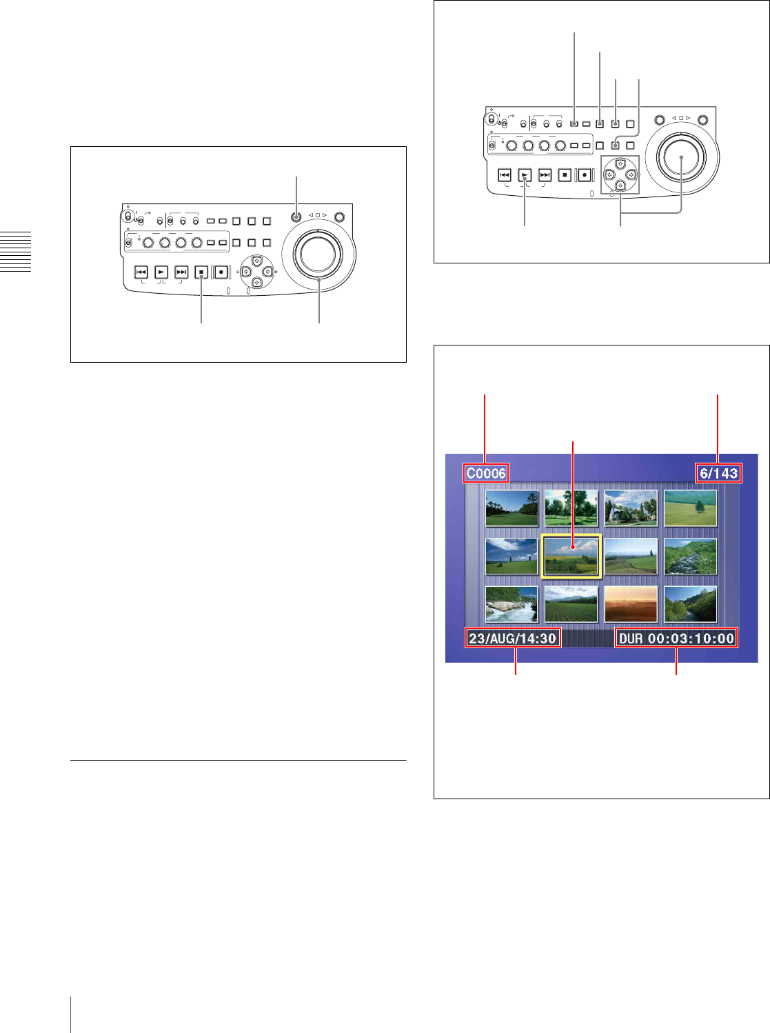
Chapter 4 Recording/Playback
52 4-2 Playback
setting), just turning the jog dial with the JOG button off
starts playback in jog mode.
Playback in shuttle mode
In shuttle mode, you can control the speed of playback by
the angular position of the shuttle dial. The range of
playback speed is ±20 times normal speed.
To carry out playback in shuttle mode, proceed as follows.
1
Press the SHUTTLE button, turning it on.
2
Turn the shuttle dial to the desired angle
corresponding to the desired playback speed.
Playback in shuttle mode starts.
3
To stop playback in shuttle mode, return the shuttle
dial to the center position, or press the STOP button.
When extended menu item 101 “SELECTION FOR
SEARCH DIAL ENABLE” is set to “dial” (factory default
setting), just turning the shuttle dial with the SHUTTLE
button off starts playback in shuttle mode.
To alternate between normal-speed playback and
shuttle mode playback
Set the shuttle dial to the position corresponding to the
desired shuttle playback speed, then switch between
normal-speed playback and shuttle playback by pressing
the PLAY and SHUTTLE buttons alternately.
For intermittent shuttle mode playback, press the STOP
and SHUTTLE buttons alternately.
4-2-3 Thumbnail Search
Cuing up a desired clip
To display the thumbnail images of all clips on the disc,
and cue up a desired clip, proceed as follows.
1
With the SUBCLIP button off, press the
THUMBNAIL button, turning it on.
The thumbnails of clips on the disc appear.
To switch between duration and time code display
in the thumbnail display
Press the COUNTER SEL button. Each press of the
button toggles between duration display and time code
display.
To escape from the thumbnail display to the full-
screen display
ACCESS
SHUTTLE JOG
THUMB
NAIL
ESSENCE
MARK
MENU
S.SEL
SET RESET
SHIFT
TOP F REV
ALL/CH-1 CH-2 CH-3 CH-4
TC
F FWD
AUDI O
END
REC
PRESET
VARIABLE
PB
PREV NEXTPLAY STOP REC
CLIP
MENU
SYSTEM
MENU
MONITOR
SEL
METER
SEL
HOLD
COUNTER
SEL
SUB
CLIP
MARK1
MARK2
IN OUT
KEY INHI
ON
OFF
NETWORK
LOCAL
REMOTE
F-RUN
R-RUN
PRESET
REGEN
INT
EXT
RP188
L/ST/R
2,33
1
ACCESS
SHUTTLE JOG
THUMB
NAIL
ESSENCE
MARK
MENU
S.SEL
SET RESET
SHIFT
TOP F REV
ALL/CH-1 CH-2 CH-3 CH-4
TC
F FWD
AUDI O
END
REC
PRESET
VARIABLE
PB
PREV NEXTPLAY STOP REC
CLIP
MENU
SYSTEM
MENU
MONITOR
SEL
METER
SEL
HOLD
COUNTER
SEL
SUB
CLIP
MARK1
MARK2
IN OUT
KEY INHI
ON
OFF
NETWORK
LOCAL
REMOTE
F-RUN
R-RUN
PRESET
REGEN
INT
EXT
RP188
L/ST/R
2
13
3
COUNTER SEL button
SUBCLIP button
Name of currently
selected clip a)
Thumbnail of currently selected clip
(first frame or specified b) frame)
Sixth clip is
selected from a
total of 143 clips.
Recording date and
time of selected clip Duration of selected clip or
time code of first frame
a) When a title has been assigned to a clip (see page 75), the title
is enclosed in double quotation marks, for example
“TITLE00001.”
b) The thumbnail frame can be specified by a menu selection
when the clip is recorded (see page 98).
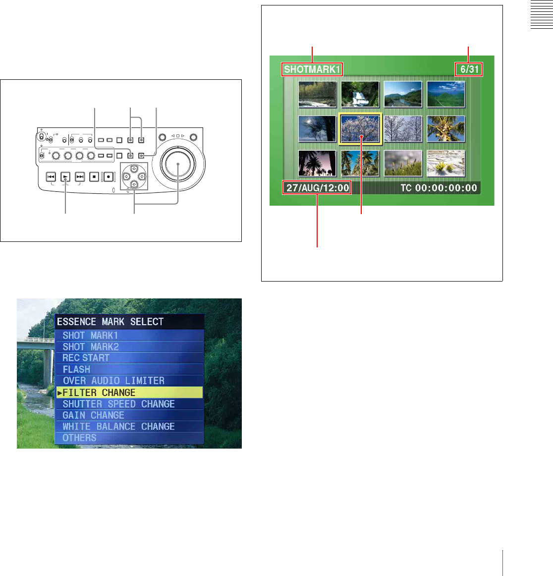
Chapter 4 Recording/Playback
53
4-2 Playback
Press the THUMBNAIL button, turning it off.
2
Use the arrow buttons or the jog dial to select the
desired clip.
You can select clips with the following operations.
Press the PREV or NEXT button: Move to the
previous or next clip.
Press the PREV or NEXT button with the SHIFT
button held down: Move to the first or last clip.
Press the F or f button with the SHIFT button held
down: Switch to the previous or next page.
3
To cue up the selected clip, press the SET button.
To start playback from the selected clip, press the
PLAY button.
Cuing up a frame including an essence
mark
Proceed as follows.
1
Hold down the SHIFT button, and press the
THUMBNAIL button, turning it on.
The essence mark selection screen appears.
To escape from the essence mark selection screen to
the previous screen
Press the RESET button.
2
Use the arrow buttons or the jog dial to select the
desired essence mark.
You can select essence marks with the following
operations.
Press the PREV or NEXT button: Move to the
previous or next essence mark.
3
Press the SET button.
Thumbnails of the frames including the selected
essence mark appear.
(The example shows the case where SHOTMARK1 is
selected as the essence mark.)
4
Use the arrow buttons or the jog dial to select the
desired frame.
You can select frames with the following operations.
Press the PREV or NEXT button: Move to the
previous or next frame.
Press the PREV or NEXT button with the SHIFT
button held down: Move to the first or last frame.
Press the F or f button with the SHIFT button held
down: Switch to the previous or next page.
5
Press the SET button to cue up the selected clip.
To start playback from the selected frame, press the
PLAY button.
ACCESS
SHUTTLE JOG
THUMB
NAIL
ESSENCE
MARK
MENU
S.SEL
SET RESET
SHIFT
TOP F REV
ALL/CH-1 CH-2 CH-3 CH-4
TC
F FWD
AUDI O
END
REC
PRESET
VARIABLE
PB
PREV NEXTPLAY STOP REC
CLIP
MENU
SYSTEM
MENU
MONITOR
SEL
METER
SEL
HOLD
COUNTER
SEL
SUB
CLIP
MARK1
MARK2
IN OUT
KEY INHI
ON
OFF
NETWORK
LOCAL
REMOTE
F-RUN
R-RUN
PRESET
REGEN
INT
EXT
RP188
L/ST/R
2,4
13,5
3
RESET button
This indicates that the thumbnail
images are the frames including the
essence mark (SHOTMARK1).
Sixth frame is selected
from a total of 31
SHOTMARK1 frames
Date and time of recording of the clip
containing the selected frame
Currently selected
SHOTMARK1 frame
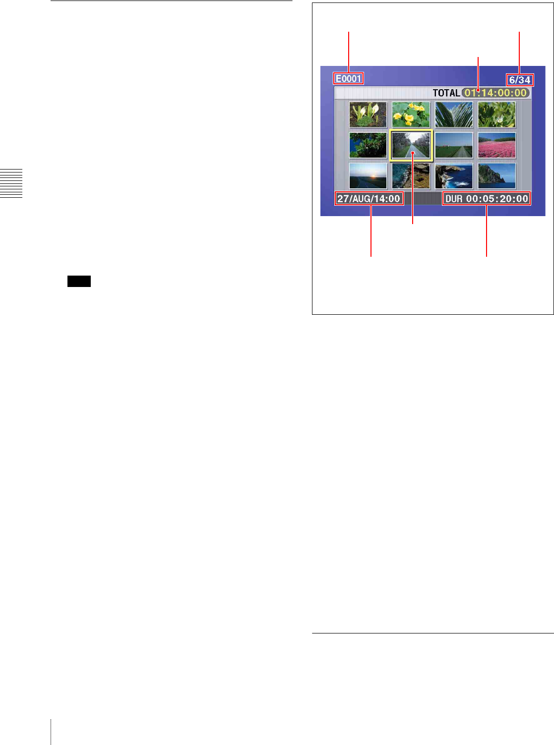
Chapter 4 Recording/Playback
54 4-2 Playback
4-2-4 Clip List Playback
You can play back clips in the order of clip lists created
with the scene selection function (see page 58).
Playing back in clip list order
Proceed as follows.
1
If the clip list that you want to play exists on the disc,
load it into the current clip list.
About the current clip list, see page 60.
For the clip list loading operation, see 5-3-1 “Loading
a Clip List From Disc Into Unit Memory” (page 68).
2
Press the SUBCLIP button, turning it on.
3
Press the PLAY button.
Playback begins from the first sub clip in the current
clip list.
Note
Depending on the length of sub clips in the clip list and
their arrangement on the disc, playback may freeze
momentarily between sub clips.
Cuing up with sub clip thumbnails
With the desired clip list loaded in the current clip list,
proceed as follows.
1
Press the SUBCLIP button and the THUMBNAIL
button, turning them on.
Thumbnails of the first frames in the sub clips appear.
To switch between duration and time code display
in the thumbnail display
Press the COUNTER SEL button. Each press of the
button toggles between duration display and time code
display.
To escape from the thumbnail display to the full-
screen display
Press the THUMBNAIL button, turning it off.
2
Use the arrow buttons or the jog dial to select the sub
clip you want to cue up.
You can select sub clips with the following operations.
Press the PREV or NEXT button: Move to the
previous or next sub clip.
Press the PREV or NEXT button with the SHIFT
button held down: Move to the first or last sub
clip.
Press the F or f button with the SHIFT button held
down: Switch to the previous or next page.
3
To cue up the selected sub clip, press the SET button.
To start playback from the selected sub clip, press the
PLAY button.
4-2-5 Repeat Playback
You can perform repeat playback for normal and clip list
playback.
Name of current clip list a) Sixth frame is selected
from a total of 34 sub clips
Total duration of
sub clips in clip list
Currently
selected sub clip
Recording date and
time of selected sub clip Duration of selected sub clip
or time code of first frame
a) When a title has been assigned to a clip list, the title is
enclosed in double quotation marks, for example “SAKURA.”

Chapter 4 Recording/Playback
55
4-2 Playback
To perform repeat playback, set extended menu item 142
“REPEAT MODE” to “play,” and then proceed as follows.
1
Insert a disc.
To perform repeat playback for normal playback,
proceed to step 3.
2
To perform repeat playback for clip list playback,
press the SUBCLIP button.
3
Press the PLAY button.
Playback starts from the saved playback position.
Normal playback: When playback of the last clip
finishes, it resumes from the start of the disc,
repeatedly playing from the first through the last
clip on the disc.
Clip list playback: When playback of the last sub clip
finishes, it resumes from the start of the clip list,
repeatedly playing from the first through the last
sub clip in the clip list.
If extended menu item 142 “REPEAT MODE” is set
to “play,” repeat playback starts from the first clip
automatically whenever you power the unit on with a
disc loaded. Clip list playback starts from the first sub
clip in the clip list.
To start repeat playback from the device
connected to the REMOTE connector
Set extended menu item 142 “REPEAT MODE” to “play,”
and then send a repeat playback command from the
external device.
For details of commands, refer to REMOTE (9-pin)
Protocol Manual for the PDW series.
To stop repeat playback
Do one of the following.
• Operate any of the playback buttons except the PLAY
button, or operate the jog or shuttle dial.
• From the external device connected to the REMOTE
connector on this unit, send a command other than the
repeat playback start command to this unit.
The unit executes the operation for the button press, jog or
search dial operation, or remote command that stops
playback. (The unit enters search mode when you conduct
a search, and stop mode at the end of the disc.)
To disable repeat playback
Set extended menu item 142 “REPEAT MODE” to “off.”
4-2-6 Locking and Deleting Clips
In the thumbnail screen, you can delete selected clips or
lock them so that they cannot be deleted. 1)
1) This is supported from firmware version 1.5.
Locking clips
Locking prevents the following operations on clips.
• Deletion
• Renaming by FAM or FTP
Notes
• Locked clips are erased along with other clips when you
format a disc.
• Clips cannot be locked or unlocked when the Write
Inhibit tab of the disc is set to the recording disabled
position, or when extended menu item 310 “REC
INHIBIT” is set to “on.”
1
With the SUBCLIP button off, press the
THUMBNAIL button, turning it on.
The thumbnails of the clips on the disc appear.
2
Use the arrow buttons or the jog dial to select the clip
to lock.
You can select clips with the following operations.
Press the PREV or NEXT button: Move to the
previous or next clip.
Press the PREV or NEXT button with the SHIFT
button held down: Move to the first or last clip.
Press the F/f button with the SHIFT button held
down: Switch to the previous or next page.
3
With the SHIFT button held down, press the
SUBCLIP button. Or press the MENU button.
The THUMBNAIL MENU appears.
To escape from the THUMBNAIL MENU to the
previous screen
Press the RESET button.
4
With LOCK/UNLOCK CLIP selected, press the SET
button.
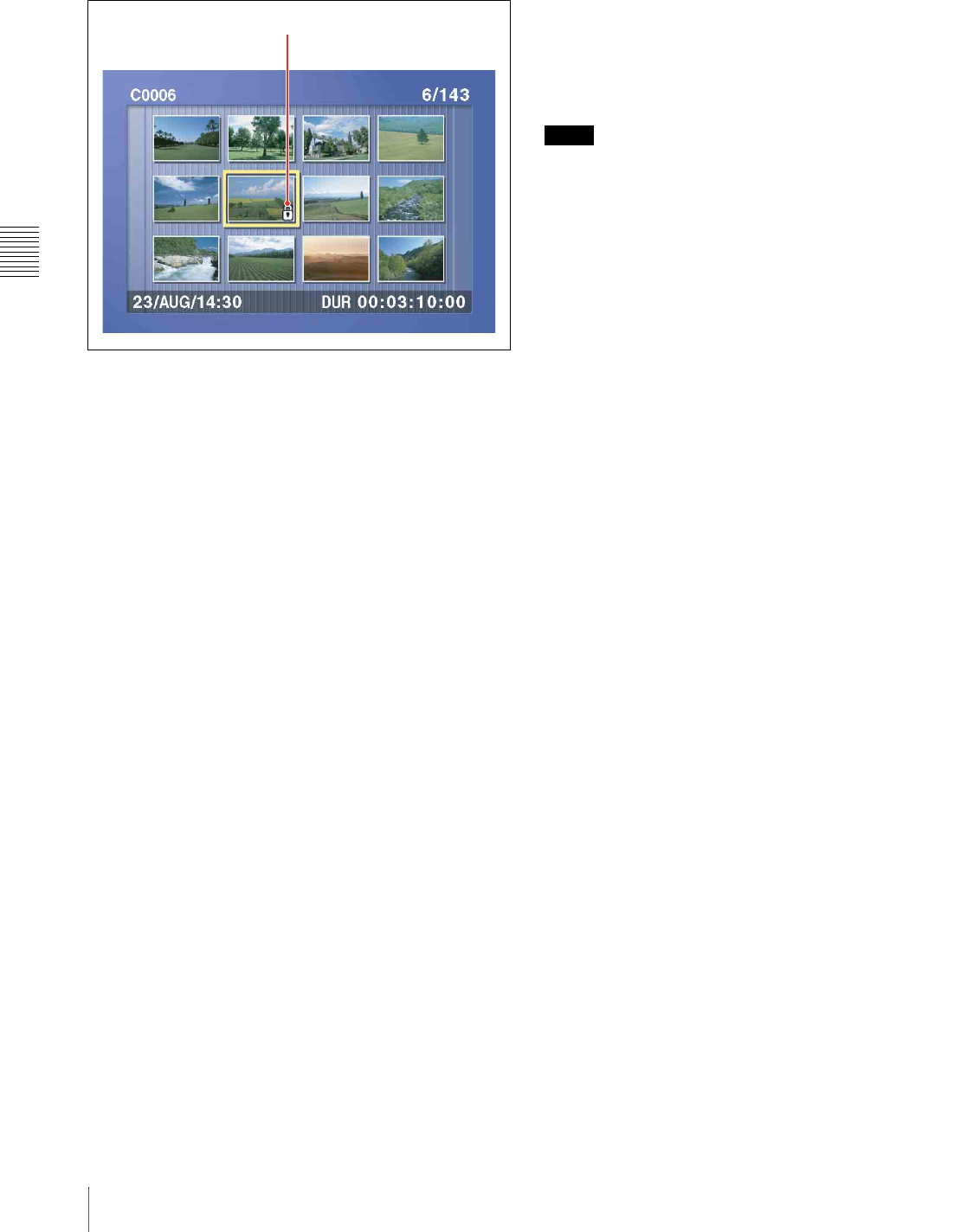
Chapter 4 Recording/Playback
56 4-2 Playback
You return to the thumbnail screen, and a lock icon
appears on the thumbnail of the selected clip to show
that it is locked.
Locked clips cannot be deleted or renamed. Unlock the
clip if you want to perform any of these operations.
To lock clips without displaying the THUMBNAIL
MENU
After carrying out step 2 in the procedure, press the STOP
button with the SHIFT button held down (shortcut
operation).
To unlock clips
Carry out step 2 of “Locking clips” to select a locked clip
(one with the lock icon displayed on its thumbnail). Then
do one of the following.
• Carry out steps 3 and 4 of “Locking clips.”
• Press the STOP button with the SHIFT button held down
(shortcut operation).
To lock all clips
1
Carry out steps 1 and 3 of “Locking clips” to display
the THUMBNAIL MENU.
2
Use the arrow buttons or the jog dial to select LOCK
ALL CLIPS, and then press the SET button.
A confirmation screen appears.
To cancel the lock operation and return to the
thumbnail screen
Do one of the following.
•Use the G or g button to select “CANCEL,” and then
press the SET button.
• Press the RESET button.
3
Use the G or g button to select “OK,” and then press
the SET button.
All clips are locked, and you return to the thumbnail
screen.
To unlock all clips
Carry out the procedure in “To lock all clips,” selecting
UNLOCK ALL CLIPS in step 2.
Deleting clips
Notes
• Clips cannot be deleted when the Write Inhibit tab of the
disc is set to the recording disabled position, or when
extended menu item 310 “REC INHIBIT” is set to “on.”
• Locked clips cannot be deleted.
• When the target clip is referenced in a clip list, the clip
list that references the clip will also be deleted.
You can use the DISC MENU to delete the last clip or all
clips. For details, see page 118.
1
With the SUBCLIP button off, press the
THUMBNAIL button, turning it on.
The thumbnails of the clips on the disc appear.
2
Use the arrow buttons or the jog dial to select the clip
to delete.
You can select clips with the following operations.
Press the PREV or NEXT button: Move to the
previous or next clip.
Press the PREV or NEXT button with the SHIFT
button held down: Move to the first or last clip.
Press the F/f button with the SHIFT button held
down: Switch to the previous or next page.
3
With the SHIFT button held down, press the
SUBCLIP button. Or press the MENU button.
The THUMBNAIL MENU appears (see step 3 of
“Locking clips” (page 55)).
To escape from the THUMBNAIL MENU to the
previous screen
Press the RESET button.
4
Use the arrow buttons or the jog dial to select DELETE
CLIP, and then press the SET button.
Thumbnails of four frames in the target clip appear.
One of the following messages appears in a
confirmation dialog, depending on whether the target
clip is referenced in a clip list.
When the target clip is not referenced in a clip list:
“DELETE CLIP?”
Lock icon

Chapter 4 Recording/Playback
57
4-2 Playback
When the target clip is referenced in a clip list:
“DELETE CLIP & CLIP LIST?” (The clip list that
references the clip will also be deleted.)
To go to the clip deletion screen without displaying
the THUMBNAIL MENU
After step 2, press the RESET button with the SHIFT
button held down (shortcut operation).
To cancel the deletion and return to the thumbnail
screen
Do one of the following.
•Use the F or f button to select “CANCEL,” and then
press the SET button.
• Press the RESET button.
5
Use the F or f button to select “OK,” and then press
the SET button.
The clip is deleted and you return to the thumbnail
screen.
To delete all clips
1
Carry out steps 1 and 3 of “Deleting clips” to display
the THUMBNAIL MENU.
2
Use the arrow buttons or the jog dial to select DELETE
ALL CLIPS, and then press the SET button.
A confirmation screen appears.
To cancel the deletion and return to the thumbnail
screen
Do one of the following.
•Use the F or f button to select “CANCEL,” and then
press the SET button.
• Press the RESET button.
3
Use the F or f button to select “OK,” and then press
the SET button.
All clips are deleted, and you return to the thumbnail
screen.

58 5-1 Overview
Chapter5
Scene Selection
5-1Overview
What is scene selection?
Scene selection is a function which allows you to select
material (clips) from the material recorded on a disc and
perform cut editing. You can do this by operating on this
unit only.
• Scene selection is a convenient way to perform cut
editing in the field and in other offline situations.
• Clip lists (edit data) created with the scene selection
function can be used on XPRI and other full-feature
nonlinear editing systems.
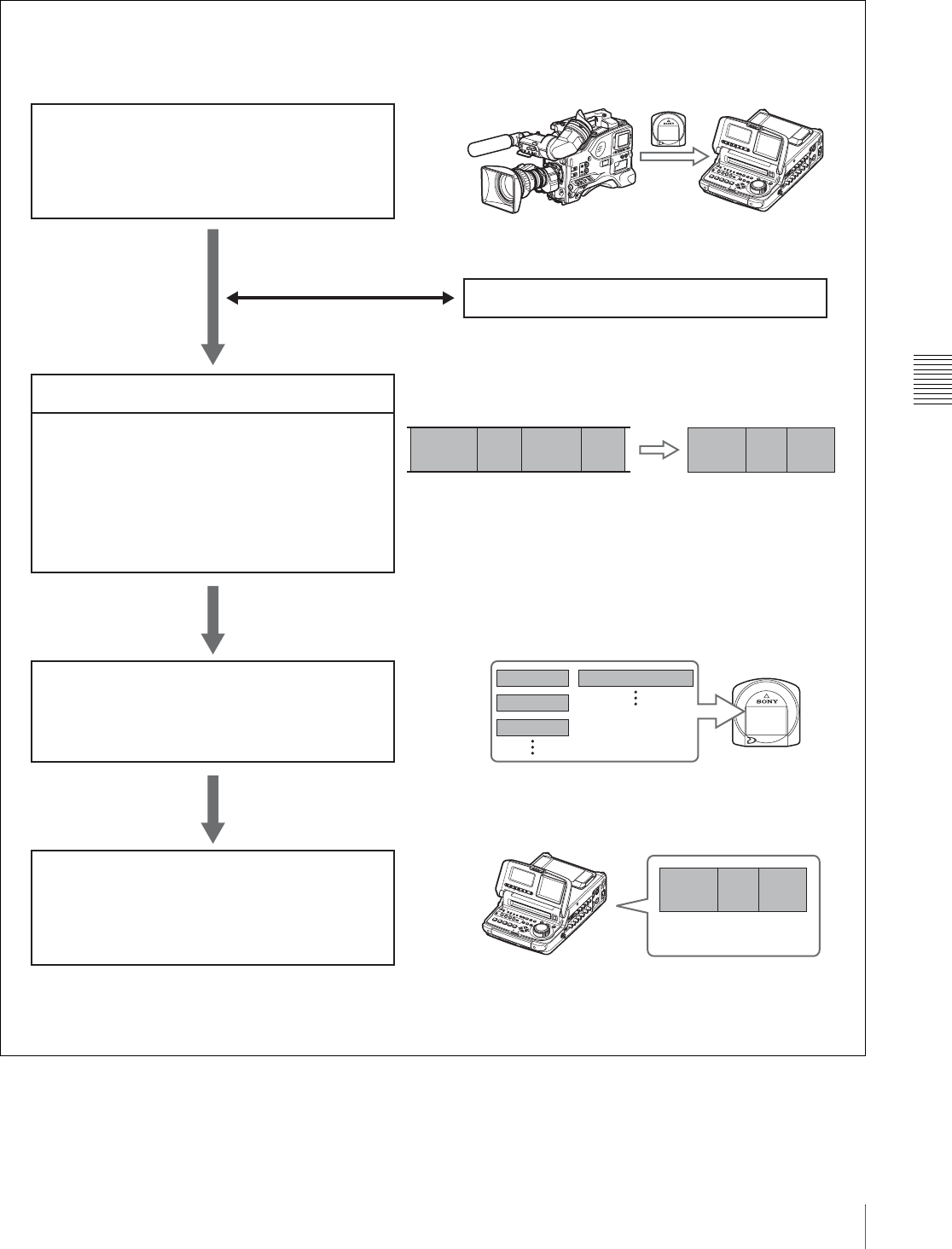
Chapter 5 Scene Selection
59
5-1 Overview
Flow of scene selection editing
SDI
SDI
Insert disc containing recorded
material into this unit
Load clip lists (see page 68)
To edit a clip list
Create and edit a clip list
• Selecting clips (see page 61)
• Reordering sub clips (see page 63)
• Trimming sub clips (see page 65)
• Deleting sub clips (see page 66)
• Previewing clip lists (see page 66)
Save the clip list to disc (see page 66)
Play back the clip list (see page 54)
Disc
PDW-510/530 PDW-R1
Clip 1 Clip 2 Clip 3 Sub
clip 1 Sub
clip 2
Sub
clip 3
Clip 1
Clip 2
Clip 3
Clip list 1
Disc
Sub
clip 1 Sub
clip 2 Sub
clip 3
PDW-R1
Recorded material Clip list 1
Select
clips
Play back clip list
Clip 4
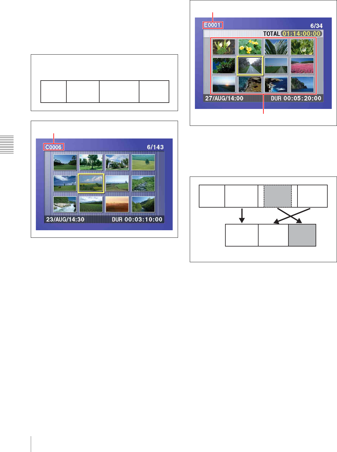
Chapter 5 Scene Selection
60 5-1 Overview
Clips
Material recorded on a disc with this unit is managed in
units called “clips.” A clip contains the material between a
recording start point (In point) and a recording end point
(Out point).
Clips have names beginning with “C” for example
“C0001.”
Clip lists
Data called a “clip list” is created when you use the scene
selection function to select desired clips from the clips
stored on a disc.
Clip lists have names beginning with “E” for example
“E0001.” You can save up to 99 clip lists on a disc.
Sub clips (clips in clip lists)
The specified clips (or parts of clips) in a clip list are called
“sub clips.” Sub clips are virtual data specifying ranges in
the original clips. Clip data in the original clips is not
overwritten.
Clip list editing (current clip list)
Clip lists cannot be edited on disc. To edit clip lists, you
need to load them, one at a time, into the unit memory.
The clip list which is currently loaded into the unit memory
is called the “current clip list.”
The current clip list is always the target of sub clip creation
and editing. Clip list playback also uses the current clip
list.
After creating and editing a clip list, you need to save it to
disc.
Clip 1
(C0001) Clip 2
(C0002) Clip 3
(C0003) Clip 4
(C0004)
In point
r
Out point
In point
r
Out point
In point
r
Out point
In point
r
Out
point
r
Clip name
Clip list name
Thumbnails of selected clips
Clip 1
(C0001) Clip 2
(C0002) Clip 3
(C0003) Clip 4
(C0004)
Sub clip 1 Sub clip 2 Sub clip 3
Example: Clip list (E0001)
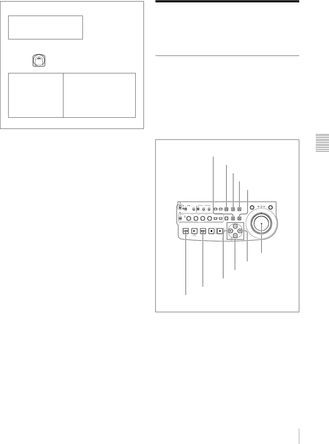
Chapter 5 Scene Selection
61
5-2 Creating Clip Lists
Clip list playback
Clips and clip lists are saved together on a disc.
Clips are played back according to clip list data.
5-2Creating Clip Lists
Before starting
Insert a disc containing recorded clips into the unit.
5-2-1 Selecting Clips
There are two ways to select clips.
• Select from the thumbnail screen.
You can select the desired clips from the thumbnail
screen.
• Select while playing back or searching.
You can select the scene to use while viewing the video.
The clips selected here are added to the current clip list as
sub clips.
To select from the thumbnail screen
1
With the SUBCLIP button off, press the
THUMBNAIL button, turning it on.
Thumbnails of the clips on the disc appear.
Unit memory
Current clip list
Can be edited (adding, deleting,
and reordering sub clips)
SAVE m
tClip list playback
and thumbnail
display
C0001 (Clip 1)
C0002 (Clip 2)
C0003 (Clip 3)
:
:
E0001 (Clip list 1)
E0002 (Clip list 2)
E0003 (Clip list 3)
:
:
E0099 (Clip list 99)
M LOAD
Disc
ACCESS
SHUTTLE JOG
THUMB
NAIL
ESSENCE
MARK
MENU
S.SEL
SET RESET
SHIFT
TOP F REV
ALL/CH-1 CH-2 CH-3 CH-4
TC
F FWD
AUDI O
END
REC
PRESET
VARIABLE
PB
PREV NEXTPLAY STOP REC
CLIP
MENU
SYSTEM
MENU
MONITOR
SEL
METER
SEL
HOLD
COUNTER
SEL
SUB
CLIP
MARK1
MARK2
IN OUT
KEY INHI
ON
OFF
NETWORK
LOCAL
REMOTE
F-RUN
R-RUN
PRESET
REGEN
INT
EXT
RP188
L/ST/R
SUBCLIP button
THUMBNAIL button
SET button
SHIFT button
RESET button
PREV button
NEXT button
G/IN button
Arrow buttons
g/OUT button
Jog dial
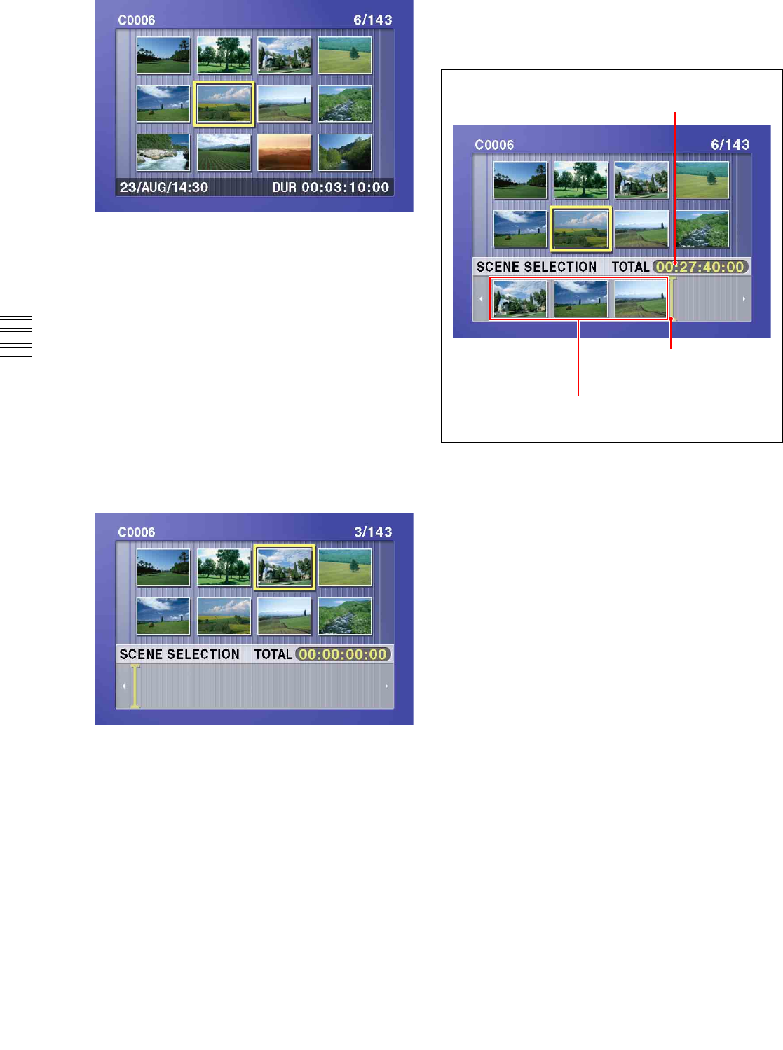
Chapter 5 Scene Selection
62 5-2 Creating Clip Lists
2
Use the arrow buttons or the jog dial to select the
desired clip.
You can also select clips with the following
operations.
Press the PREV or NEXT button: Moves to the
previous or next clip.
Press the PREV or NEXT button with the SHIFT
button held down: Moves to the first or last clip.
Press the F or f button with the SHIFT button held
down: Switches to the previous or next page.
(Does not switch when there is only one page.)
3
With the SHIFT button held down, press the SET
button.
The scene selection window appears.
To return to the original screen
Press the RESET button.
4
Press the SET button.
The selected clip is added to the current clip list as a
sub clip.
At the same time, the scene selection window closes
and you return to the original thumbnail screen.
5
Repeat steps 2 to 4 until you have added all of the
desired clips to the current clip list.
You can select the same clip any number of times.
The scene selection window displays thumbnails of
the sub clips that have been added to the current clip
list. The cursor in the window indicates the position
where the next sub clip will be added.
To move the cursor in the scene selection window
After carrying out step 3 to display the scene selection
window, press the G or g button.
6
When you have finished selecting all the clips you
want, save the current clip list to disc.
See 5-2-6 “Saving the Current Clip List to Disc” (page
66).
To select while playing back and searching
(quick scene selection)
1
With the SUBCLIP button off, and the clip displayed
in full-screen mode, play back the clip or conduct a
search to find the point that you want to set as the In
point.
To display the desired clip in full-screen mode
If the thumbnail screen is displayed, use the arrow
buttons or jog dial to select the clip to display in full-
screen mode, and then press the SET button.
Total duration of sub clips in
the current clip list
Cursor (indicates where the
next sub clip will be added)
Thumbnails of sub clips already
added to the current clip list
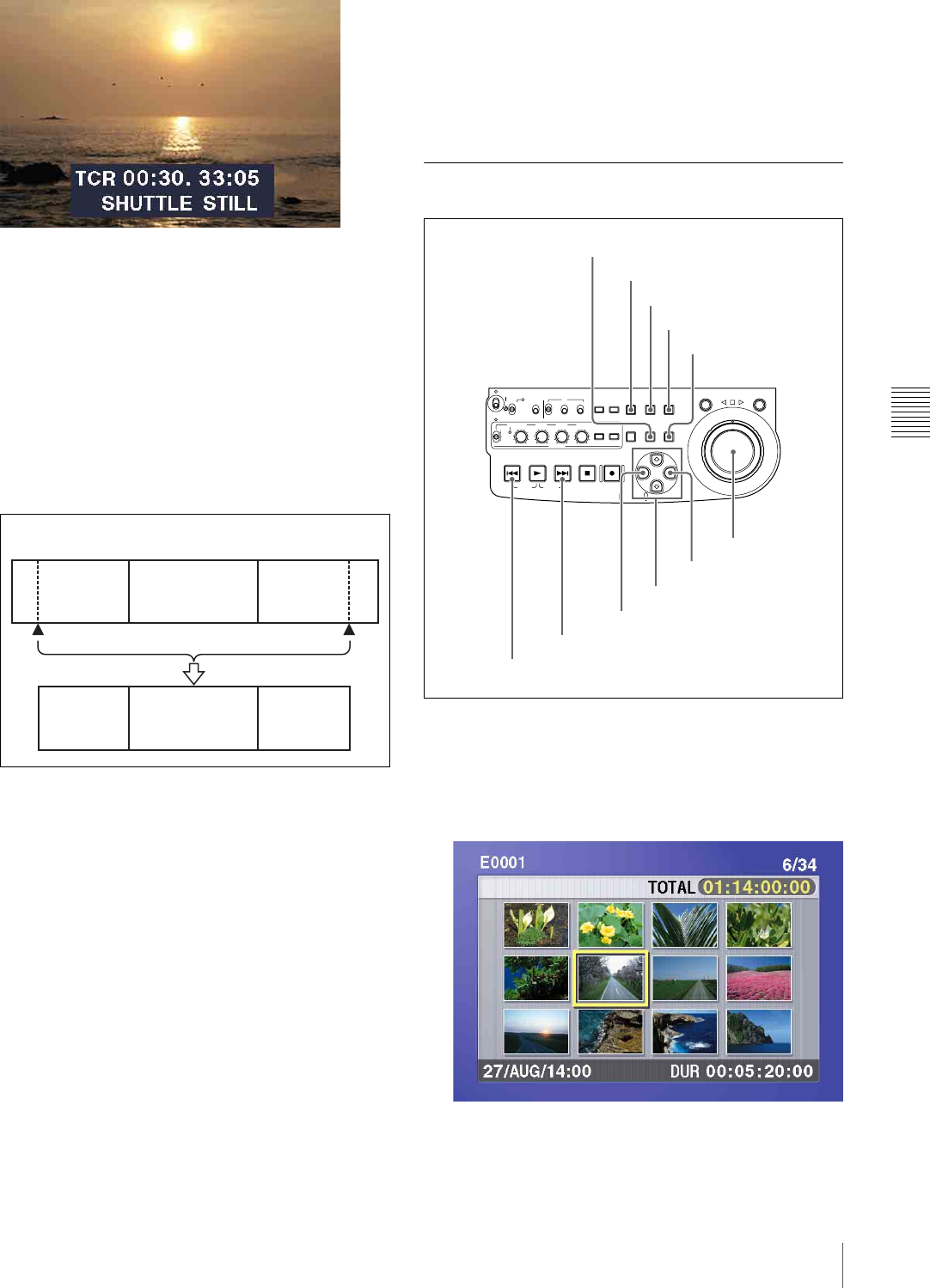
Chapter 5 Scene Selection
63
5-2 Creating Clip Lists
To search
Use the jog and shuttle dials.
2
At the point you want to set as the In point, hold down
the G/IN button and press the SET button.
An In point is set, and the IN indicator lights.
3
In the same way, search for the point you want to set
as the Out point, and then hold down the g/OUT
button and press the SET button.
An Out point is set, and the OUT indicator lights.
To check the duration
Press the G/IN button and the g/OUT button at the
same time.
The duration appears on the screen.
To reset an In point or Out point
With the G/IN button or g/OUT button held down,
press the RESET button.
4
With the SHIFT button held down, press the SET
button.
The section between the In point and Out point is
added to the end of the current clip list as a sub clip.
When you set In and Out points stretching across
several clips
One sub clip is created for each of the clips.
5
Repeat steps 1 to 4 until you have added all of the clips
you want to the current clip list.
6
Save the current clip list to disc.
See 5-2-6 “Saving the Current Clip List to Disc” (page
66).
5-2-2 Reordering Sub Clips
1
Press the SUBCLIP button, turning it on.
2
Press the THUMBNAIL button, turning it on.
Thumbnails of the sub clips in the current clip list
appear.
If the clip list you want to edit is not the current clip
list
Clip 1
Sub clip 1
Clips recorded on the disc
Clip 2 Clip 3
Sub clip 2 Sub clip 3
In point Out point
ACCESS
SHUTTLE JOG
THUMB
NAIL
ESSENCE
MARK
MENU
S.SEL
SET RESET
SHIFT
TOP F REV
ALL/CH-1 CH-2 CH-3 CH-4
TC
F FWD
AUDI O
END
REC
PRESET
VARIABLE
PB
PREV NEXTPLAY STOP REC
CLIP
MENU
SYSTEM
MENU
MONITOR
SEL
METER
SEL
HOLD
COUNTER
SEL
SUB
CLIP
MARK1
MARK2
IN OUT
KEY INHI
ON
OFF
NETWORK
LOCAL
REMOTE
F-RUN
R-RUN
PRESET
REGEN
INT
EXT
RP188
L/ST/R
SUBCLIP button
THUMBNAIL button
SET button
SHIFT button
RESET button
PREV button
NEXT button
G/IN button
Arrow buttons
g/OUT button
Jog dial
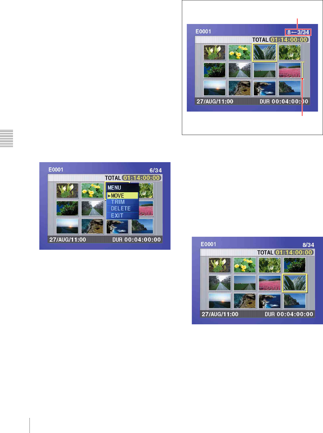
Chapter 5 Scene Selection
64 5-2 Creating Clip Lists
Load the clip list from the disc into the unit memory
(see page 68).
To return to the full-screen display
Press the THUMBNAIL button, turning it on.
3
Use the arrow buttons or the jog dial to select the
desired sub clip.
You can also select sub clips with the following
operations.
Press the PREV or NEXT button: Moves to the
previous or next sub clip.
Press the PREV or NEXT button with the SHIFT
button held down: Moves to the first or last sub
clip.
Press the F or f button with the SHIFT button held
down: Switches to the previous or next page.
(Does not switch when there is only one page.)
4
With the SHIFT button held down, press the SET
button.
The sub clip operation menu appears.
To return to the thumbnail screen without moving
the sub clip
Do one of the following.
• Press the F or f button to select EXIT, and then
press the SET button.
• Press the RESET button.
5
Use the F or f button to select MOVE, and then press
the SET button.
The sub clip movement screen appears. The clip
selected in step 3 appears surrounded by a frame.
To return to the previous screen
Press the RESET button.
6
Use the arrow buttons or the jog dial to move the
cursor to the position where you want to move the
selected sub clip.
To return to the previous screen
Press the THUMBNAIL button.
7
Press the SET button.
The sub clip thumbnail screen appears, allowing you
to check the results of the sub clip movement.
8
Save the current clip list to disc.
See 5-2-6 “Saving the Current Clip List to Disc” (page
66).
Indicates that the third sub clip will be
moved to the position of the eighth sub clip.
Cursor indicating the move destination
for the selected sub clip
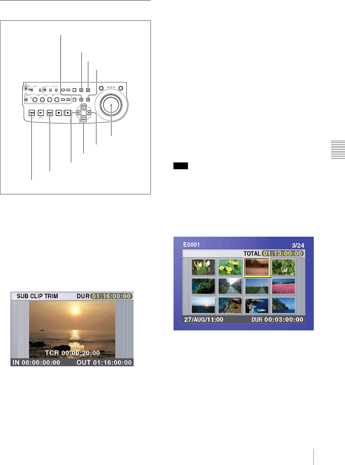
Chapter 5 Scene Selection
65
5-2 Creating Clip Lists
5-2-3 Trimming Sub Clips
1
Carry out steps 1 to 4 of 5-2-2 “Reordering Sub Clips”
to select a sub clip and display the sub clip operation
menu.
2
Use the F or f button to select TRIM, and then press
the SET button.
The first frame of the selected sub clip appears. The
first and last frames are set as provisional In and Out
points, and the IN and OUT indicators light.
In this state, you can play back and search the entire
disc.
To cancel the trim and return to the previous
screen
With the SHIFT button held down, press the SET
button.
3
Play back and search the disc to find scenes to set new
In and Out points.
4
At the scene where you want to set a new In or Out
point, hold down the G/IN button (to change the In
point) or the g/OUT button (to change the Out point)
and press the SET button.
Depending on the button that you pressed, a new In or
Out point is set.
To change both the In and Out points
Carry out steps 3 and 4 for both the In and Out points.
To reset the In or Out point
With the G/IN button or g/OUT button held down,
press the RESET button. The In or Out point is
restored to the value it had before the sub clip trim
screen opened.
To cue up the In or Out point
With the G/IN button held down, press the PREV
button. Or with the the g/OUT button held down, press
the NEXT button.
Note Note
You can escape from the sub clip trim screen to full-
screen display without executing a trim if you press the
THUMBNAIL button.
5
Once you have set the new In point or Out point, hold
down the SHIFT button and press the SET button.
The trim is executed, and you return to the sub clip
thumbnail display.
To cancel the trim
Reset the In or Out point to the value it had before you
entered the sub clip trim screen, and then hold down
the SHIFT button and press the SET button.
6
Save the current clip list to disc.
See 5-2-6 “Saving the Current Clip List to Disc” (page
66).
ACCESS
SHUTTLE JOG
THUMB
NAIL
ESSENCE
MARK
MENU
S.SEL
SET RESET
SHIFT
TOP F REV
ALL/CH-1 CH-2 CH-3 CH-4
TC
F FWD
AUDI O
END
REC
PRESET
VARIABLE
PB
PREV NEXTPLAY STOP REC
CLIP
MENU
SYSTEM
MENU
MONITOR
SEL
METER
SEL
HOLD
COUNTER
SEL
SUB
CLIP
MARK1
MARK2
IN OUT
KEY INHI
ON
OFF
NETWORK
LOCAL
REMOTE
F-RUN
R-RUN
PRESET
REGEN
INT
EXT
RP188
L/ST/R
THUMBNAIL button
SET button
SHIFT button
RESET button
PREV button
NEXT button
G/IN button
F/f buttons
g/OUT button
Jog dial
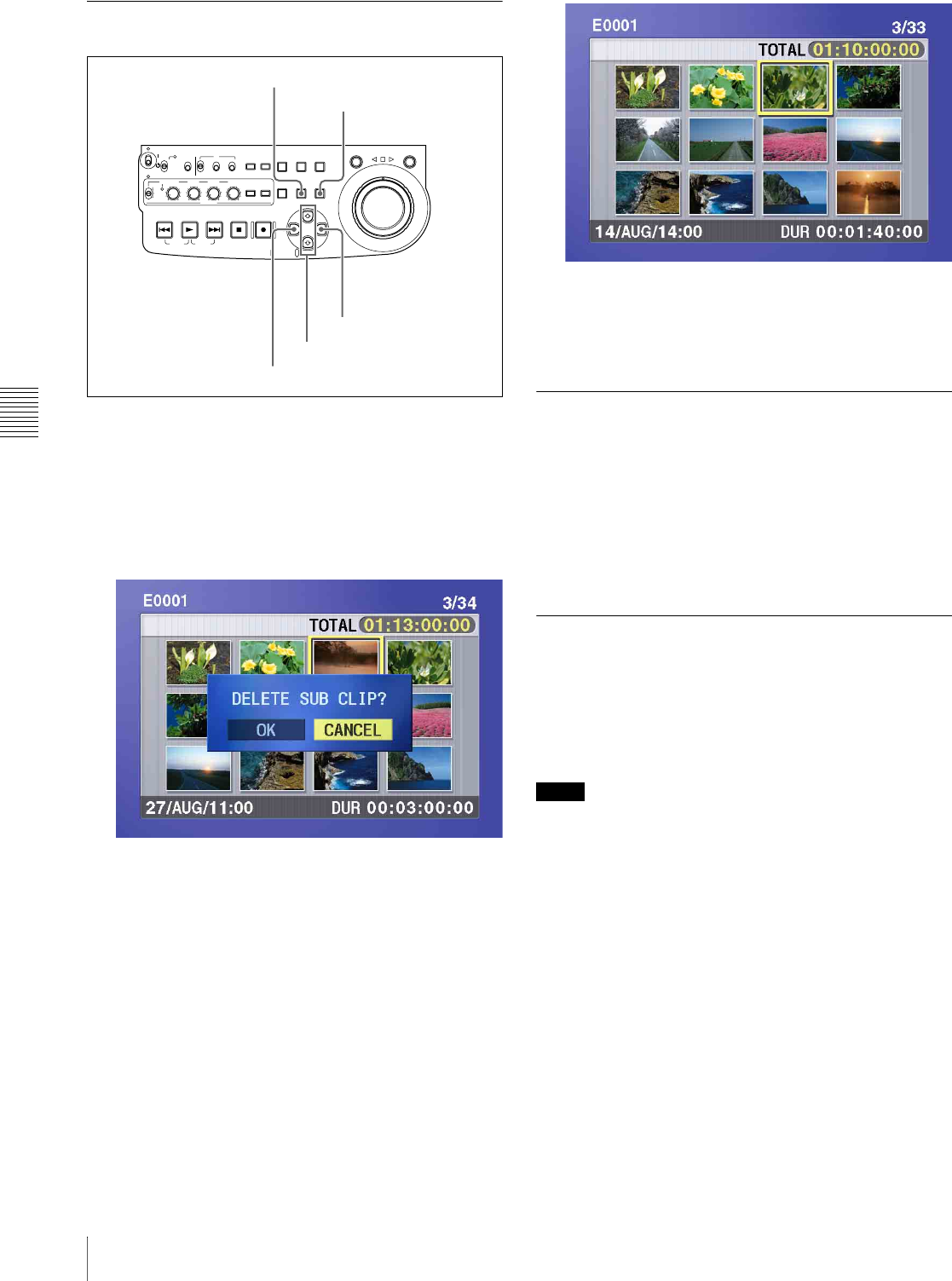
Chapter 5 Scene Selection
66 5-2 Creating Clip Lists
5-2-4 Deleting Sub Clips
1
Carry out steps 1 to 4 of 5-2-2 “Reordering Sub Clips”
to select a sub clip and display the sub clip operation
menu.
2
Use the F or f button to select DELETE, and then
press the SET button.
The sub clip deletion screen appears.
To cancel the deletion and return to the previous
screen
Do one of the following
•Use the G or g button to select CANCEL, and then
press the SET button.
• Press the RESET button.
The screen returns to the sub clip thumbnail display.
3
Use the G or g button to select OK, and then press the
SET button.
The selected sub clip is deleted, and the screen returns
to the sub clip thumbnail display.
4
Save the current clip list to disc.
See 5-2-6 “Saving the Current Clip List to Disc” (page
66).
5-2-5 Previewing the Current Clip
List
Press the SUBCLIP button, turning it on, and then press
the PLAY button.
When the THUMBNAIL button is lit, playback starts from
the beginning of the selected sub clip.
When the THUMBNAIL button is not lit, playback starts
from the first sub clip in the clip list.
5-2-6 Saving the Current Clip List to
Disc
The current clip list is not saved to disc unless you carry
out this procedure. After editing clip list data, you should
always save it to disc.
Notes
• The current clip list is not saved to disc if the disc’s write
protect tab is set to the recording disabled position.
• Unless you carry out this procedure, the unit does not
enter the standby state even if you set the on/standby
switch to the 1 position. Follow the message that
appears and return the on/standby switch to the & side,
and then save the clip list or, if you do not need it, clear
it (see page 69).
ACCESS
SHUTTLE JOG
THUMB
NAIL
ESSENCE
MARK
MENU
S.SEL
SET RESET
SHIFT
TOP F REV
ALL/CH-1 CH-2 CH-3 CH-4
TC
F FWD
AUDI O
END
REC
PRESET
VARIABLE
PB
PREV NEXTPLAY STOP REC
CLIP
MENU
SYSTEM
MENU
MONITOR
SEL
METER
SEL
HOLD
COUNTER
SEL
SUB
CLIP
MARK1
MARK2
IN OUT
KEY INHI
ON
OFF
NETWORK
LOCAL
REMOTE
F-RUN
R-RUN
PRESET
REGEN
INT
EXT
RP188
L/ST/R
SET button
RESET button
G/IN button
g/OUT button
F/f buttons
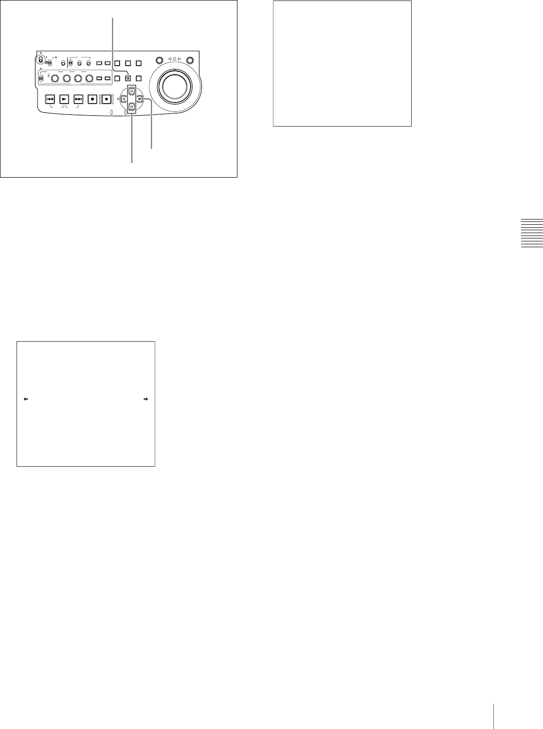
Chapter 5 Scene Selection
67
5-2 Creating Clip Lists
1
Display the CLIP menu.
See “To display the CLIP menu” (page 68).
2
Use the F or f button to move the cursor to SAVE, and
then press the g button.
A list of clip lists appears.
“NEW FILE” is displayed for clip lists without any
registered data.
The date of creation or the title is displayed for each
clip list.
To switch between display of dates of creation,
titles, and clip list names
With the SHIFT button held down, press the SET
button.
With each press, the display changes as follows.
Dates of creation > titles > clip list names > dates of
creation...
3
Use the F or f button or the jog dial to select the
desired clip list, and then press the g button.
A confirmation message like the one shown below
appears.
To cancel the save
Press the MENU button.
4
Press the SET button.
The current clip list is saved to disc.
To assign a title to a clip list
Use the supplied PDZ-1 Proxy Browsing Software.
For details, see the PDZ-1 online help.
ACCESS
SHUTTLE JOG
THUMB
NAIL
ESSENCE
MARK
MENU
S.SEL
SET RESET
SHIFT
TOP F REV
ALL/CH-1 CH-2 CH-3 CH-4
TC
F FWD
AUDI O
END
REC
PRESET
VARIABLE
PB
PREV NEXTPLAY STOP REC
CLIP
MENU
SYSTEM
MENU
MONITOR
SEL
METER
SEL
HOLD
COUNTER
SEL
SUB
CLIP
MARK1
MARK2
IN OUT
KEY INHI
ON
OFF
NETWORK
LOCAL
REMOTE
F-RUN
R-RUN
PRESET
REGEN
INT
EXT
RP188
L/ST/R
SET button
g/OUT button
F/f buttons
SAVE
E0001 04/08/08 21:57
E0002 04/08/24 11:15
E0003 04/08/25 15:30
E0004 NEW FILE
E0005 NEW FILE
E0006 NEW FILE
E0007 NEW FILE
E0009 NEW FILE
TITLE : SHIFT+SET KEY
E0008 NEW FILE
CLIP MENU
SAVE E0005 OK ?
SAVE : SET KEY
TO MENU : MENU KEY
SAVE CLIP LIST
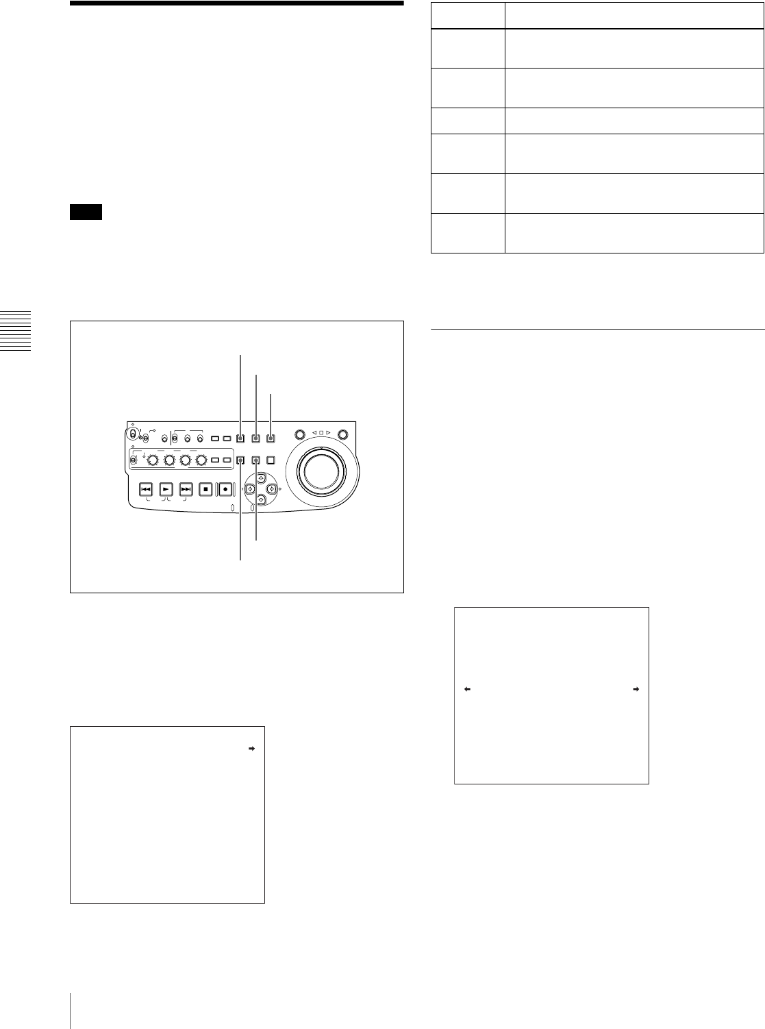
Chapter 5 Scene Selection
68 5-3 Managing Clip Lists (CLIP Menu)
5-3 Managing Clip Lists
(CLIP Menu)
After you create a clip list, you can use the CLIP menu to
save it to disc, load it from disc into the unit memory, and
delete it from the disc.
The CLIP menu also allows you to clear and edit the
current clip list.
Note Note
Carry out CLIP menu operations with the unit stopped. If
the message “STOP ONCE, THEN EXECUTE.” appears,
press the STOP button.
To display the CLIP menu
With the THUMBNAIL button off, hold down the SHIFT
button and press the SUBCLIP button.
If the THUMBNAIL button is lit
Press the THUMBNAIL button to turn it off.
The CLIP menu appears.
To escape from the CLIP menu.
Press the MENU button.
5-3-1 Loading a Clip List From Disc
Into Unit Memory
The clip list loaded with this procedure becomes the
current clip list.
1
Display the CLIP menu.
See “To display the CLIP menu” (page 68).
2
Use the F button to move the cursor to LOAD, and
then press the g button.
A list of clip lists appears.
The date of creation or the title is displayed for each
clip list.
To switch between display of dates of creation,
titles, and clip list names
With the SHIFT button held down, press the SET
button.
With each press, the display changes as follows.
Dates of creation > titles > clip list names > dates of
creation...
ACCESS
SHUTTLE JOG
THUMB
NAIL
ESSENCE
MARK
MENU
S.SEL
SET RESET
SHIFT
TOP F REV
ALL/CH-1 CH-2 CH-3 CH-4
TC
F FWD
AUDI O
END
REC
PRESET
VARIABLE
PB
PREV NEXTPLAY STOP REC
CLIP
MENU
SYSTEM
MENU
MONITOR
SEL
METER
SEL
HOLD
COUNTER
SEL
SUB
CLIP
MARK1
MARK2
IN OUT
KEY INHI
ON
OFF
NETWORK
LOCAL
REMOTE
F-RUN
R-RUN
PRESET
REGEN
INT
EXT
RP188
L/ST/R
MENU button
THUMBNAIL button
SUBCLIP button
SET button
SHIFT button
LOAD
SAVE
DELETE
CLEAR
TC PRESET
SORT BY : name
CLIP MENU
Item Operation
LOAD Load a clip list from the disc into the current
clip list (see page 68)
SAVE Save the current clip list to disc (see page
66)
DELETE Delete a clip list from the disc (see page 69)
CLEAR Clear the current clip list from the unit
memory (see page 69)
TC
PRESET Preset the first time code in the current clip
list (see page 69)
SORT BY Sort clip lists by name or date of creation
(see page 70)
LOAD
E0001 04/08/08 21:57
E0002 04/08/24 11:15
E0003 04/08/25 15:30
E0004 NEW FILE
E0005 NEW FILE
E0006 NEW FILE
E0007 NEW FILE
E0009 NEW FILE
TITLE : SHIFT+SET KEY
E0008 NEW FILE
CLIP MENU

Chapter 5 Scene Selection
69
5-3 Managing Clip Lists (CLIP Menu)
3
Use the F or f button or the jog dial to select the
desired clip list, and then press the g button
A confirmation message like the one shown below
appears.
4
Press the SET button.
The selected clip list is loaded into the unit memory as
the current clip list.
If an unsaved current clip list exists in the unit
memory
A warning message like the following appears.
“CLIP LIST IS NOT SAVED. OVERWRITE CLIP
LIST?”
Press the SET button to overwrite the unsaved current clip
list, or press the MENU button to quit without overwriting.
To display thumbnails of the sub clips in the
newly loaded current clip list
Press the SUBCLIP button, and then press the
THUMBNAIL button.
5-3-2 Deleting Clip Lists From a Disc
1
Display the CLIP menu.
See “To display the CLIP menu” (page 68).
2
Use the F or f button to move the cursor to DELETE,
and then press the g button.
A list of clip lists appears.
The date of creation or the title is displayed for each
clip list. The date of creation is always displayed for
clip lists without titles.
To switch between display of dates of creation,
titles, and clip list names
With the SHIFT button held down, press the SET
button.
With each press, the display changes as follows.
Dates of creation > titles > clip list names > dates of
creation...
3
Use the F or f button or the jog dial to select the
desired clip list, and then press the g button.
A confirmation message like the one shown below
appears.
4
Press the SET button.
The selected clip list is deleted from the disc.
5-3-3 Clearing the Current Clip List
From the Unit Memory
This operation clears the current clip list, so that no clip list
is loaded in the unit memory.
1
Display the CLIP menu.
See “To display the CLIP menu” (page 68).
2
Use the F or f button to move the cursor to CLEAR,
and then press the g button.
A message like the one shown below appears.
3
Press the SET button.
The current clip list is cleared from the unit memory.
5-3-4 Presetting the Initial Time
Code of the Current Clip List
When the unit is powered on, and when you insert a new
disc, the initial time code of the current clip list is set to
LOAD E0002 OK ?
LOAD : SET KEY
TO MENU : MENU KEY
LOAD CLIP LIST
DELETE E0001 OK ?
DELETE : SET KEY
TO MENU : MENU KEY
DELETE CLIP LIST
CLEAR OK ?
CLEAR : SET KEY
TO MENU : MENU KEY
CLEAR CLIP LIST

Chapter 5 Scene Selection
70 5-3 Managing Clip Lists (CLIP Menu)
“00:00.00.00.” You can set the initial time code to any
value.
1
Load an existing clip list for which you want to set the
initial time code into to the unit memory as the current
clip list.
For details, see 5-3-1 “Loading a Clip List From Disc
Into Unit Memory” (page 68).
2
Display the CLIP menu.
See “To display the CLIP menu” (page 68).
3
Use the f button to select TC PRESET, and then press
the g button.
A screen like the one shown below appears.
The time code shown in this screen is the current initial
time code of the current clip list. If you have already
set the initial time code for this clip list, that time code
is displayed.
4
Repeat the following operations to set a time code
value (LTC).
• Press the G or g button to select the digit to replace.
• Rotate the jog dial to set a value.
5
Press the SET button.
The initial time code (LTC) of the current clip list is
set. When the clip list is played back, time code will
start counting from that value.
To check the time code after setting it
Press the SUBCLIP button, turning it on. The initial
time code of the current clip list appears in the TCR
field.
6
Save the current clip list to disc.
See 5-2-6 “Saving the Current Clip List to Disc” (page
66).
5-3-5 Sorting Clip Lists
Proceed as follows to sort the existing clip lists by clip list
name or by date of creation.
1
Display the CLIP menu.
See “To display the CLIP menu” (page 68).
2
Use the F or f button to select SORT BY, and then
press the g button.
A screen like the one shown below appears.
3
Use the F or f button to select NAME or DATE.
NAME: Sort in ascending order by clip list name
(factory default setting).
DATE: Sort by date of creation, with the newest clip
list first.
4
Press the G button to return to the CLIP menu screen.
The clip lists are sorted by the method you chose in
step 3.
Unused clip lists are excluded from the sort.
00:00.00.00
INC/DEC : JOG DIAL
SHIFT : ( )( ) KEY
DATA SAVE : SET KEY
TO MENU : MENU KEY
CLIP LIST TC PRESET
SORT BY : name
*NAME(A-Z)
DATE(NEWEST FIRST)
CLIP MENU

Chapter 5 Scene Selection
71
5-4 Using PDZ-1 Proxy Browsing Software
5-4Using PDZ-1 Proxy
Browsing Software
When a computer with the PDZ-1 Proxy Browsing
Software installed is connected to this unit, you can
transfer the proxy AV data and metadata files recorded on
a disc to the computer. On the computer side, PDZ-1
enables you to browse the proxy AV data, add or modify
metadata (titles, comments, essence marks, etc.), or create
a clip list.
The modified metadata and the created clip list can then be
written back to the disc loaded in this unit.
Live logging function
If you set extended menu item 258 “LIVE LOGGING” to
“on,” you can use PDZ-1 to do the following during
recording of high-resolution data: view proxy AV data,
perform cut editing of the data, and enter metadata.
For more information about PDZ-1 functions and
operations, refer to the PDZ-1 help.
System requirements
The following are required to use PDZ-1.
• Computer:
- When using the live logging function:
PC with Intel Pentium 4 CPU, at least 2 GHz (installed
memory: at least 512 MB)
- When not using the live logging function:
PC with Intel Pentium III CPU, at least 1 GHz
(installed memory: at least 512 MB)
• Operating system: Microsoft Windows 2000 Service
Pack 4 or higher, or Microsoft Windows XP
Professional Service Pack 1 or higher
• Web browser: Internet Explorer 6.0 Service Pack 1 or
higher
• DirectX: DirectX 8.1b or higher
To install PDZ-1
Insert the supplied CD-ROM (PDZ-1 Proxy Browsing
Software) in the CD-ROM drive of the computer and
execute the Setup.exe file, then follow the installation
instructions.
For details, refer to the ReadMe file contained on the CD-
ROM disc.
Notes
• Make sure that the hard disk drive on which the work
folder to store the material transferred from this unit has
adequate free space. The amount of proxy AV data
transferred is about 1.4 GB per disc (when recording in
the DVCAM format).
• To transfer files between the computer and this unit
requires this unit’s IP address and other network-related
settings to be made.
For details of the network-related settings, see “To
change network settings” (page 115).
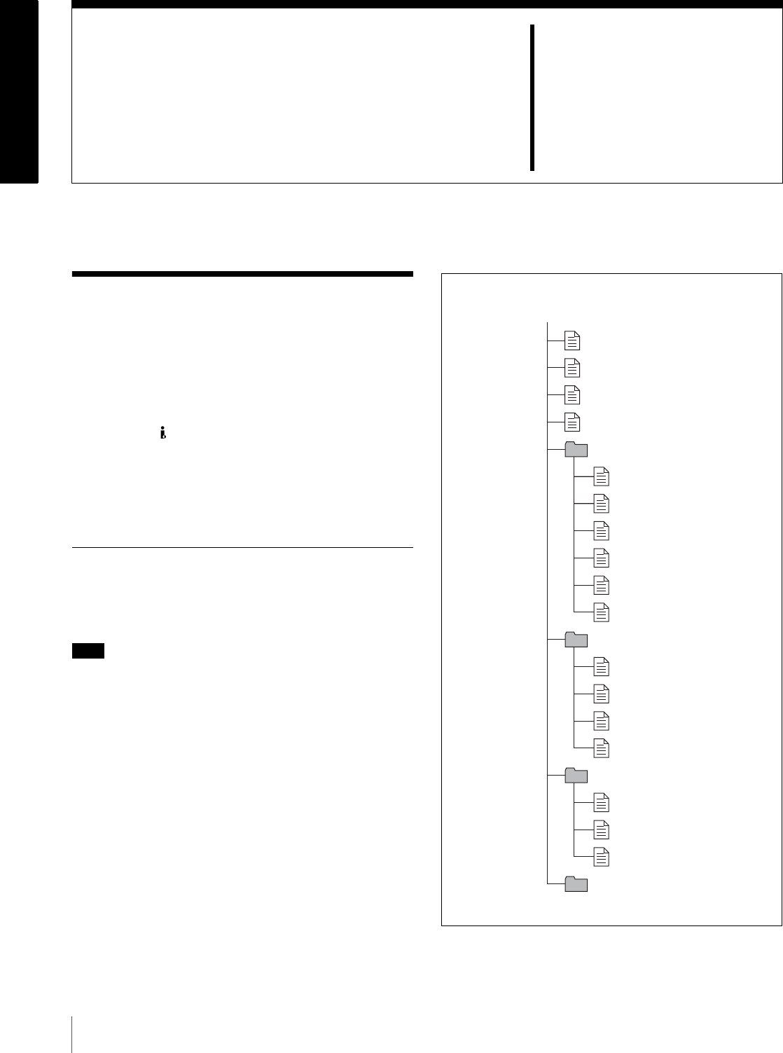
72 6-1 Overview
Chapter6
File Operations
6-1Overview
A remote computer can be connected to this unit and used
to operate on recorded data which has been saved in data
files, such as video and audio data files.
There are two ways to connect a remote computer.
• FAM connection
Connect the S400 (i.LINK) connector on this unit to
the i.LINK (IEEE1394) connector on the remote
computer, using an i.LINK cable (see page 78).
• FTP connection
Connect the network connectors on this unit and the
remote computer, using a network cable (see page 80).
6-1-1 Directory Structure
The following figure shows the directory structure of discs
visible to a remote computer.
Note
This structure is not the same as the actual structure
recorded on the disc.
a) Root directory
b) Only when sub item “NAMING FORM” of basic menu item 036 is set to
“free”
root a)
INDEX.XML
ALIAS.XML b)
Clip
Edit
Sub
General
DISCMETA.XML
MEDIAPRO.XML
C0001.MXF
C0001M01.XML
C0002.MXF
C0002M01.XML
C0003.MXF
C0003M01.XML
E0001E01.SMI
E0001M01.XML
E0002E01.SMI
E0002M01.XML
C0001S01.MXF
C0002S01.MXF
C0003S01.MXF
Chapter 6 File Operations
73
6-1 Overview
6-1-2 File Operation Restrictions
This section explains which operations are possible on
files stored in each directory.
When required, the following operation tables distinguish
reading and overwriting from partial reading and
overwriting.
Read: Read data sequentially from the start to the end
of the file.
Partial read: Read only a part of the data in the file.
Overwrite: Overwrite data sequentially from the start
to the end of the file.
Partial overwrite: Overwrite data to a part of the file
only.
Root directory
a) Only when sub item “NAMING FORM” of basic menu item 036 is set to
“free”
b) Only files which can be overwritten by XDCAM
Notes
• Directories cannot be created in the root directory.
• The directories in the root directory (Clip, Edit, Sub, and
General) cannot be deleted or renamed.
Clip directory
a) With firmware version 1.5 and higher, the unit can handle files with user-
defined names in the “C*” part.
b) Possible with firmware version 1.5 and higher.
c) Only files which are 2 seconds or longer in length, in a format matching
the line mode format (525/625) and recording format (IMX50/IMX40/
IMX30/DVCAM) and number of audio channels of the recorded sections
of the disc, and which can be overwritten by XDCAM.
d) Only when the write inhibit tab on the disc is set to enable recording, and
when extended menu item 310 “REC INHIBIT” is set to “off.” With
firmware version 1.4x and lower, only the most recently recorded clip may
be deleted. With firmware version 1.5 and higher, any clip may be selected
and deleted.
e) Only files which can be overwritten by XDCAM
f) With firmware version 1.5 and higher, when the “C*” part of a C*.MXF
file name is changed, a C*M01.XML with the same name in the “C*” part
is also changed automatically.
g) When a C*.MXF file is created, a C*M01.XML file with the same name
in the “C*” part is created automatically.
File name Content Operations
Read/
Partial read
Overwrite/
Partial
overwrite
Rename Create Delete
INDEX.XML Contains data for management of
the audio/video material on the
disc.
YesNoNoNoNo
ALIAS.XML a) Contains conversion tables for
assigning user-defined names to
clips and clip lists.
YesNoNoNoNo
DISCMETA.XML Contains metadata to indicate the
disc properties. Yes Ye s b) No No No
MEDIAPRO.XML Contains a list of audio/video
material on the disc, basic
properties, related information, and
information about access methods.
YesNoNoNoNo
Other files Files other than the above −No −No −
File name Content Operations
Read/
Partial read
Overwrite/
Partial
overwrite
Rename Create Delete
C*.MXF a) Clip file created by recording (MXF
file)
*: 0001 to 4999
Yes N o No b) Ye s c) Yes d)
C*M01.XML a) Metadata file generated
automatically when C*.MXF file is
created.
*: 0001 to 4999
Yes Ye s e) No f) No g) No h)
Other files Files other than the above −No −No −
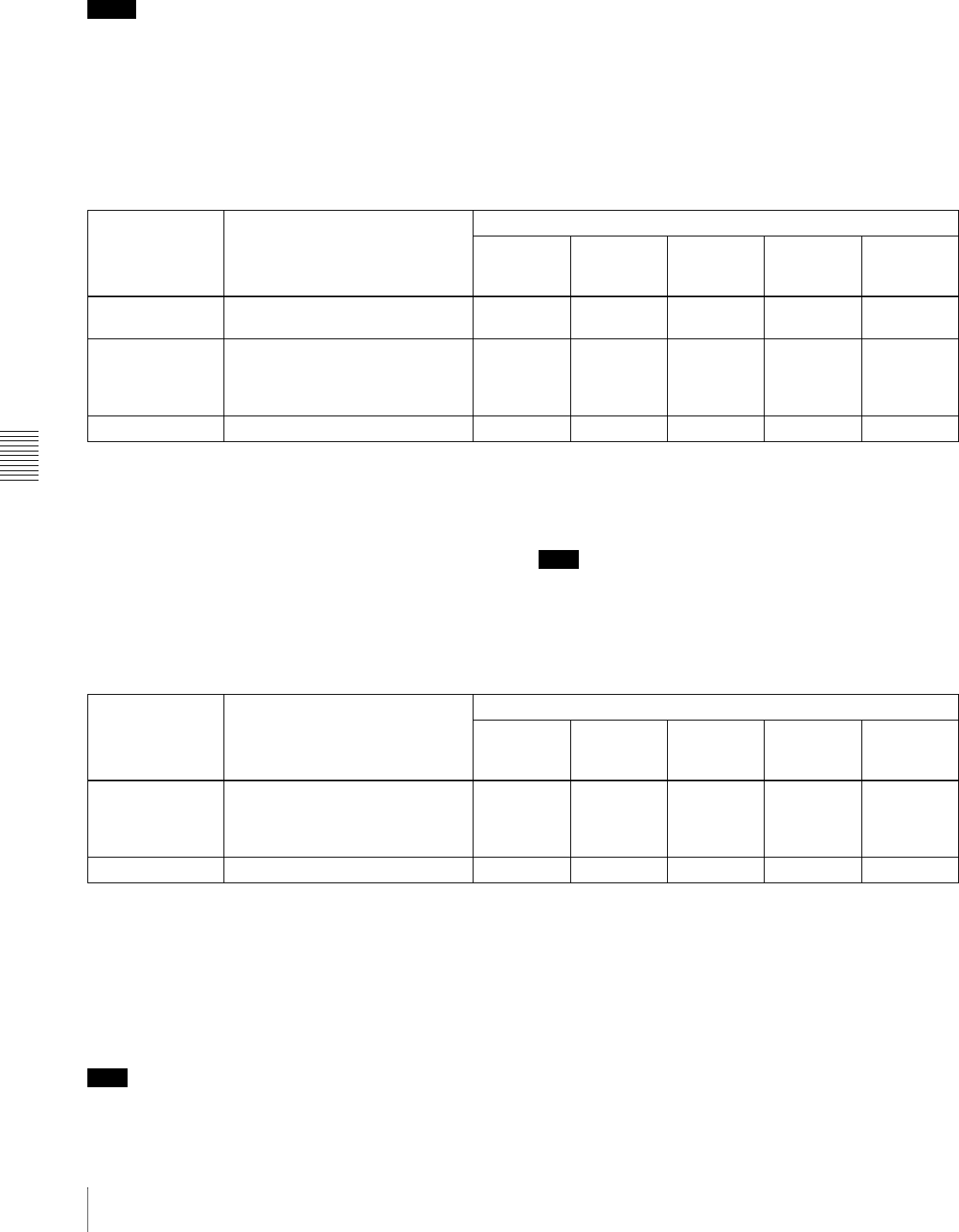
Chapter 6 File Operations
74 6-1 Overview
h) When a C*.MXF file is deleted, the C*M01.XML file with the same name
in the “C*” part is also deleted automatically.
Notes
• Directories cannot be created in the Clip directory.
• When the following operations, supported by version 1.5
and higher XDCAM devices, are carried out on a disc,
then it becomes impossible for version 1.4x and lower
XDCAM devices to record new clips or delete existing
clips on that disc. (The only possible operations are
playback and disc formatting.)
- Writing of clips with user-defined names
- Locking of clips
- Deletion of clips (except the last recorded clip)
• If you attempt to write a C*.MXF file which does not
meet the conditions specified as remark c) on this table
via a FAM connection, a Windows error message
appears to the effect that the file or directory is corrupt
and cannot be read.
Edit directory
a) With firmware version 1.5 and higher, the unit can handle files with user-
defined names in the “E*E01” part.
b) Only files which can be overwritten by XDCAM. Partial overwriting is not
possible.
c) Possible with firmware version 1.5 and higher.
d) Only files which can be overwritten by XDCAM
e) Only when the write inhibit tab on the disc is set to enable recording, and
when extended menu item 310 “REC INHIBIT” is set to “off.”
f) With firmware version 1.5 and higher, when the “E*E01” part of an
E*E01.SMI file name is changed, an E*M01.XML file with the same
name in the “E*” part is generated automatically.
g) When an E*E01.SMI file is created, an E*M01.XML file with the same
name in the “E*” part is created automatically.
h) When an E*E01.SMI file is deleted, the E*M01.XML file with the same
name in the “E*” part is also deleted automatically.
Note
Directories cannot be created in the Edit directory.
Sub directory
a) With firmware version 1.5 and higher, the unit can handle files with user-
defined names in the “C*” part.
b) With firmware version 1.5 and higher, when the “C*” part of a C*.MXF
file name is changed, a C*S01. MXF file with the same name in the “C*”
part is generated automatically.
c) When a C*.MXF file is created, a C*S01.XML file with the same name in
the “C*” part is created automatically.
d) When a C*.MXF file is deleted, the C*S01.XML file with the same name
in the “C*” part is also deleted automatically.
Note
Directories cannot be created in the Sub directory.
File name Content Operations
Read/
Partial read
Overwrite/
Partial
overwrite
Rename Create Delete
E*E01.SMI a) Clip list file
*: 0001 to 0099 Yes Ye s b) No c) Ye s d) Yes e)
E*M01.XML a) Metadata file generated
automatically when E*E01.SMI file
is created.
*: 0001 to 0099
Yes Ye s b) No f) No g) No h)
Other files Files other than the above −No −No −
File name Content Operations
Read/
Partial read
Overwrite/
Partial
overwrite
Rename Create Delete
C*S01.MXF a) Proxy AV data (MXF) file generated
automatically when a C*.MXF file is
created.
*: 0001 to 4999
Yes N o No b) No c) No d)
Other files Files other than the above −No −No −
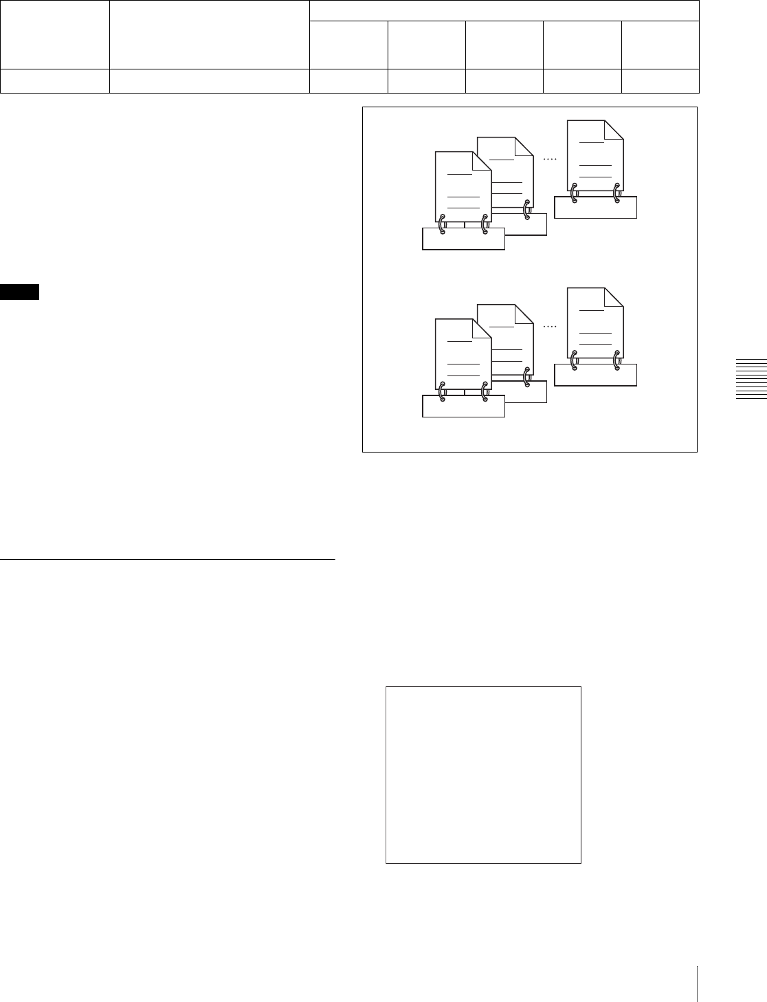
Chapter 6 File Operations
75
6-1 Overview
General directory
a) UTF-8 file names can be up to 63 bytes in length. (Depending on the
character type, file names (including extension) may be limited to 21
characters.)
b) Only when the write inhibit tab on the disc is set to enable recording, and
when extended menu item 310 “REC INHIBIT” is set to “off.”
The following directory operations are possible in the
General directory.
• Directory creation (up to 64 levels, including the
General directory)
• Deletion and renaming of directories
Notes
• The maximum number of files which can be created on
a disc, including directories, is 5,000.
• File names and directory names can use letters, numbers,
and symbols from the Unicode 2.0 (UTF-8) character
set. 1)
However, the following control characters and symbols
cannot be used.
- Control characters: U+0000 to U+001F, U+007F
- Symbols: ", *, /, :, <, >, ', ?, \, |
1) This is supported from firmware version 1.4. However, the following
character codes cannot be used by FAM connections.
U+010000, U+020000, U+030000, U+040000, U+050000, U+060000,
U+070000, U+080000, U+090000, U+0A0000, U+0B0000, U+0C0000,
U+0D0000, U+0E0000, U+0F0000, U+100000
(There are no limits to characters which can be used by FTP connections.)
6-1-3 Assigning User-Defined Clip
Titles
By default, clips on each disc are assigned names in the
range C0001.MXF to C4999.MXF. For this reason, two
discs can contain clips with the same names. The
automatic title generation function allows you to assign
titles to all of the clips on several discs, which facilitates
clip management. For example, if the titles TITLE00001 to
TITLE00020 are assigned to clips C0001.MXF to
C0020.MXF on disc 1, then the titles TITLE00021 to
TITLE00037 are assigned to clips C0001.MXF to
C0017.MXF on disc 2.
Proceed as follows to specify a title and assign it to
recorded clips.
1
Press the MENU button.
2
Rotate the jog or shuttle dial to display menu item 035.
3
With the SHUTTLE button held down, rotate the jog
or shuttle dial to select “on.”
4
Press the SET button.
The clip title naming screen appears.
File name Content Operations
Read/
Partial read
Overwrite/
Partial
overwrite
Rename Create Delete
Any file Yes Yes Yes a) Ye s Yes b)
C0020.MXF
TITLE00020
C0002.MXF
TITLE00002
TITLE00001
C0001.MXF
C0017.MXF
TITLE00037
C0002.MXF
TITLE00022
TITLE00021
C0001.MXF
Clips recorded on Disc 1
Clips recorded on Disc 2
CLIP TITLE NAMING SELECT
*TITLE - disable
PREFIX - TITLE
NUMERIC - 00001
ITEM-035

Chapter 6 File Operations
76 6-1 Overview
5
With the STOP button held down, rotate the jog or
shuttle dial to move the asterisk (*) on the left of the
menu items to “TITLE.”
The asterisk indicates the selected item.
6
With the SHUTTLE button held down, rotate the jog
or shuttle dial to select “enable.”
The automatic title generation function is enabled.
7
With the STOP button held down, rotate the jog or
shuttle dial to move the asterisk to the item that you
want to set first.
PREFIX: A string of up to 10 characters. The
allowable characters are alphanumeric characters,
symbols (! # $ % & ' ( ) + , - . ; = @ [ ] ^ _ { } ~),
and the space character.
NUMERIC: A five-digit number (00001 to 99999) to
serve as the initial value of the serial number.
8
Rotate the jog or shuttle dial to select the character
position to set.
9
With the SHUTTLE button held down, rotate the jog
or shuttle dial to select the character to set.
10
Repeat steps 8 and 9 as required.
When you are setting the “NUMERIC” item, you can
press the RESET button to return the initial value of
the serial number to 00001 (factory default setting).
11
Carry out steps 7 to 10 to set the other item.
12
Press the SET button.
The title is saved.
To check the titles of recorded clips
Press the THUMBNAIL button to display the thumbnail
screen, and select the clip whose title you want to check.
The title of the selected clip appears at the upper left of the
screen.
See “Cuing up a desired clip” (page 52) for more
information about the thumbnail screen.
Notes
• The value of the serial number is incremented by 1 every
time a title is generated. When the value reaches 99999,
the next number restarts from 00001.
• Duplicate clip titles can be generated if you reset the
serial number after recording several clips or the same is
true depending on the value setting. Care should be taken
when setting the serial number.
• The “PREFIX” setting is saved in memory banks, but the
“NUMERIC” setting is not saved (see page 96).
6-1-4 Assigning User-Defined Clip
and Clip List Names
The following standard format names are assigned
automatically to clips and clip lists that are created or
recorded by XDCAM devices.
Clips: C0001.MXF to C4999.MXF
Clip lists: E0001E01.SMI to E0099E01.SMI
This unit can handle clips and clip lists with user-defined
names as well as names in the standard format. 1)
1) This is supported from firmware version 1.5.
Limitations
• Letters, numbers and symbols from the Unicode 2.0
character set can be used.
However, the following control characters and symbols
cannot be used.
- Control characters: U+0000 to U+001F, U+007F
- Symbols: ", *, /, :, <, >, ?, \, |
• Depending on the character type, the length of user-
defined names (the “C*” or “E*E01” part) may be
limited to 14 characters. (The limit for ASCII characters
is 56 characters.)
• All file name extensions are converted automatically to
uppercase.
• Titles are used as user-defined clip names on this unit.
Therefore, the available characters are limited to those
supported by the title function.
• Files generated along with clips and clip lists use the
same names (the “C*” or “E*” part of the following file
names).
- Clips: Metadata files (C*M01.XML), proxy AV data
files (C*S01.MXF)
- Clip lists: Metadata files (E*M01.XML)
• The following names cannot be assigned.
- Clips:C0000.MXF
- Clip lists: E0000E01.SMI, E0100E01.SMI to
E9999E01.SMI, E0000.SMI, E0100.SMI to
E9999.SMI
• The following names should be avoided.
- Clips: C5000.MXF to C9999.MXF
- Clip lists: E0001.SMI to E0099.SMI
To assign clip names on this unit
The title assigned to clip becomes its clip name (file
name).
Notes
• When the first letter of the title setting with basic menu
item 035 “CLIP TITLE NAMING SELECT” is a space
or period (.), the clip name is the title string minus the
first letter.
• An FTP client that supports UTF-8 is required to use
Unicode characters other than ASCII characters.
Command prompt FTP commands do not support UTF-
8.
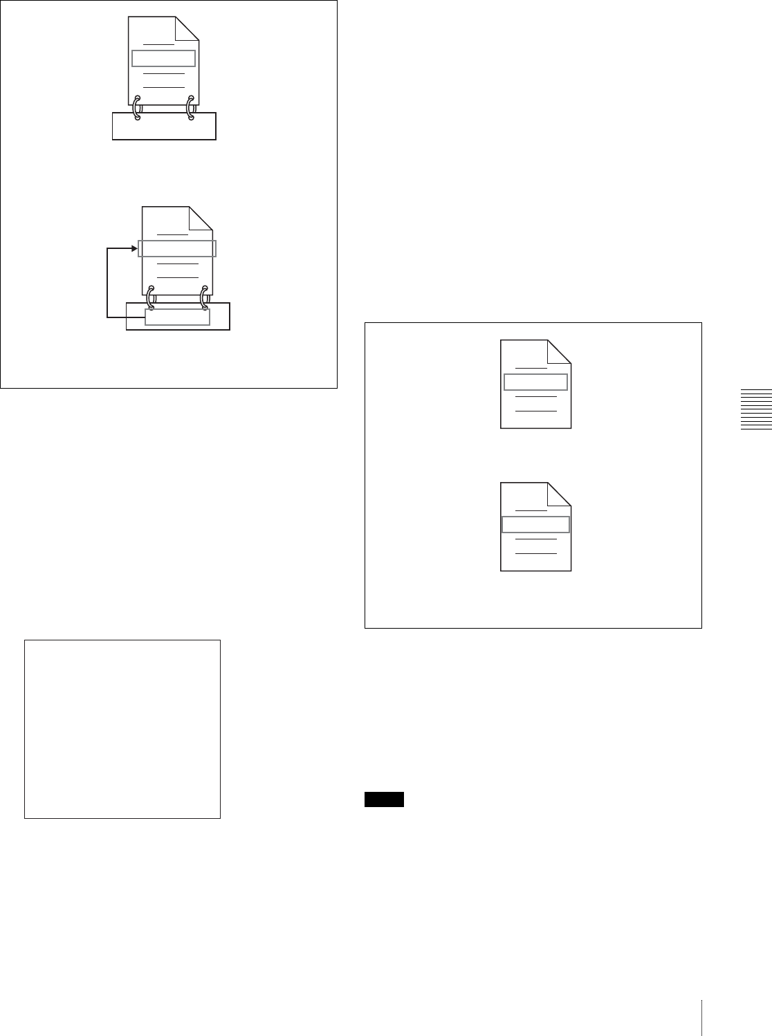
Chapter 6 File Operations
77
6-1 Overview
1
Before you start, set the “TITLE” sub item of basic
menu item 035 “CLIP TITLE NAMING SELECT” to
“enable,” and set a title (see the previous section).
2
Press the MENU button.
3
Rotate the jog dial or the shuttle dial to display menu
item 036.
4
With the STOP button held down, rotate the jog dial or
the shuttle dial to move the “*” to the left of the item
names to “NAMING FORM.”
The “*” indicates the selected item.
5
With the SHUTTLE button held down, rotate the jog
dial or the shuttle dial to select “free.”
You are now able to use clips and clip lists with user-
defined names.
6
With the STOP button held down, rotate the jog dial or
the shuttle dial to move the “*” to the left of “AUTO
NAMING.”
7
With the SHUTTLE button held down, rotate the jog
dial or the shuttle dial to select “title.”
8
Press the SET button.
The same name will now be given to newly recorded
clips.
To use clips and clip lists with user-defined
names over FAM and FTP connections
Carry out steps 2 to 5 of “To assign clip names on this
unit,” and then press the SET button.
It is now possible to write, transfer, and rename clips and
clip lists with user-defined names over file access mode
(FAM) connections (see page 78) and FTP connections
(see page 80).
To check clip names
Press the THUMBNAIL button to display the thumbnail
screen, and select the clip whose name you want to check.
The name of the selected clip appears at the upper left of
the screen.
See “Cuing up a desired clip” (page 52) for more
information about the thumbnail screen.
Notes
• The item at the upper left of the screen is displayed
according to the following order of priority.
Title > User-defined clip name > Standard format clip
name
Therefore, the display of this item changes as following,
depending on whether there is a title.
- When a title has been set as a clip name on this unit,
for clips recorded on this unit, the title is displayed.
C0001.MXF
TITLE00001
TITLE00001.MXF
TITLE00001
When the “AUTO NAMING” sub item of basic menu item
036 is set to “C****”
When the “AUTO NAMING” sub item of basic menu item
036 is set to “title”
FILE NAMING
* NAMING FORM - C****
AUTO NAMING - C****
END
ITEM-036
Fuji.MXF
Sakura.SMI
Able to use clips with user-defined names over FAM and FTP
connections
Able to use clip lists with user-defined names over FAM and FTP
connections

Chapter 6 File Operations
78 6-2 File Access Mode File Operations
- The user-defined name or standard format name is
displayed for clips without a title.
• If the firmware of your XDCAM device is version 1.4x
or lower, clips with user-defined names appear as
“C5000” to “C9999,” in order of recording.
6-2 File Access Mode File
Operations
File access mode operating environment
Operating system requirements for file operations by file
access mode (called FAM below) are as follows.
• Computer operating system: Microsoft Windows 2000
Service Pack 4 or higher, or Microsoft Windows XP
Preparations
Do the following on the remote computer and this unit.
• Install the FAM driver on the remote computer (see the
next section).
• Set extended menu item 215 “i.LINK MODE” to
“FAM.”
See 7-3-2 “Extended Menu Operations” (page 108) for
more information about how to make this setting.
To install the FAM driver
Insert the supplied CD-ROM (PDZ-1 Proxy Browsing
Software) in the CD-ROM drive of the computer and
execute the Setup.exe file, then follow the installation
instructions.
For details, refer to the ReadMe file contained on the CD-
ROM disc.
Note
Use Version 1.4 or higher of the FAM driver. The FAM
driver on the supplied CD-ROM is Version 1.4 or higher.
If a FAM driver is already installed on your computer,
check the version.
To check the version, click “Add or Remove Programs”
(Windows XP) or “Add/Remove Programs” (Windows
2000), select “ProDisc,” and then click “Click here for
support information.”
6-2-1 Making FAM Connections
1
If there is a disc loaded in this unit, put the unit into the
following state.
• Recording, playback, search and other disc
operations (see page 16): Stopped
• THUMBNAIL button (see page 13): Off
• Disc access by DELETE, FORMAT, and so on in
the System menu (see page 117): Stopped
• Unsaved current clip list: Save or clear
• Extended menu item 258 “LIVE LOGGING”: off

Chapter 6 File Operations
79
6-2 File Access Mode File Operations
2
If this unit is connected to a remote computer by FTP,
log out from the FTP session (see page 80).
3
Connect the S400 (i.LINK) connector on this unit to
the i.LINK (IEEE1394) connector on the remote
computer, using an i.LINK cable (see connections
illustration on page 27).
Windows recognizes this unit as a removable disc, and
displays one of the following icons on the remote
computer’s task bar:
•Windows 2000:
•Windows XP:
The remote computer is now able to perform file
operations when a disc is inserted into this unit.
Note
You will not be able to log in if you put the unit into
the state described in step 1 after connecting the cable.
To log in, disconnect the cable, put the unit into the
state described in step 1, and connect it again.
Operation limitations during FAM connections
• Control panel and LCD panel operations are disabled,
except for operations with the EJECT and STATUS
buttons.
• This unit cannot be controlled from devices connected to
the REMOTE connector (D-sub 9-pin) and S400
(i.LINK) connector.
• Signal input to this unit and signal output from this unit
are stopped.
6-2-2 Operating on Files
1
Start Explorer.
Check that a drive letter has been assigned to this unit.
(The drive letter will differ depending on the number
of other peripherals connected to the remote
computer.)
2
Use Explorer to perform file operations on the disc
loaded in this unit.
You can operate in the same way that you operate on
local drives and files on network computers.
Notes
• If you power this unit off during an FAM
connection, the data transferred thus far is discarded.
• All file operations are not possible for some types of
files.
For details, see 6-1-2 “File Operation Restrictions”
(page 73).
To eject discs from a remote computer
Right click the icon representing this unit in Explorer, and
select Eject from the menu which appears.
6-2-3 Exiting File Operations
Note
Do not disconnect the cable before performing steps 1 to 3.
1
Do one of the following on the or icon
displayed in the remote computer’s taskbar.
• Double click.
• Right click, and select one of the following
commands from the menu which appears.
-Windows 2000: Unplug or eject hardware
-Windows XP: Safely Remove Hardware
•Windows 2000: The Unplug or Eject Hardware
dialog appears.
•Windows XP: The Safely Remove Hardware dialog
appears.
2
Select “Sony XDCAM PDW-R1 IEEE 1394 SBP2
Device” and click Stop.
The Stop a Hardware device dialog appears.
3
Select “Sony XDCAM PDW-R1 IEEE 1394 SBP2
Device” and click OK.
•Windows 2000: A confirmation message appears.
•Windows XP: “Sony XDCAM PDW-R1 IEEE
1394 SBP2 Device” is deleted from the Hardware
devices list.
This unit can now resume normal operations. (The
limitations described in “Operation limitations during
FAM connections” (see page 79) no longer apply.)
4
Disconnect the i.LINK cable as required.
To reconnect
To reconnect after exiting file operations, do one of the
following, depending on whether an i.LINK cable is
connected.
i.LINK cable is not connected: Connect this unit and a
remote computer with an i.LINK cable.
i.LINK cable is connected: Disconnect the i.LINK cable
from either this unit or the remote computer, wait for
at least 10 seconds, and then reconnect the
disconnected cable.
The unit is powered off and an i.LINK cable is
connected: Power the unit on.

Chapter 6 File Operations
80 6-3 FTP File Operations
To disable FAM connections
Execute one of the procedures described in the previous
section “Reconnecting” to make a FAM connection
between this unit and the remote computer. To disable
FAM connections, set extended menu item 215 “i.LINK
MODE” to “AV/C.”
For more information about how to make this setting, see
7-3-2 “Extended Menu Operations” (page 108).
6-3 FTP File Operations
File operations between this unit and a remote computer
can be carried out by the File Transfer Protocol (called
FTP below).
Preparations
1
Connect the network connectors of this unit and a
remote computer with a network cable (see
connections illustration on page 26). Or connect this
unit to the network to which the remote computer is
connected (see connections illustration on page 26).
2
Set the IP address and other network setting items for
this unit.
For details, see “To change network settings” (page
115).
If network settings have already been made
Check the IP address of this unit.
For details, see “To check the assigned IP address”
(page 115).
3
Set the remote control switch to “NETWORK” (see
page 12).
6-3-1 Making FTP Connections
FTP connections between this unit and a remote computer
can be made with either of the following.
• The command prompt
•FTP client software
This section explains how to use the command prompt. For
more information about using FTP client software, refer to
the documentation of the FTP client software on your
system.
Note
An FTP client that supports UTF-8 is required to use
Unicode characters other than ASCII characters.
Command prompt FTP commands do not support UTF-8.
To log in
If this unit is connected to a remote computer with a FAM
connection, first exit file operations on the FAM
connection (see page 79).
1
Load a disc into this unit and put the unit into the
following state.

Chapter 6 File Operations
81
6-3 FTP File Operations
• Recording, playback, search and other disc
operations (see page 16): Stopped
• THUMBNAIL button (see page 13): Off
• Disc access by DELETE, FORMAT, and so on in
the System menu (see page 117): Stopped
• Unsaved current clip list: Save or clear
• Extended menu item 258 “LIVE LOGGING”: off
Note
Login is not possible unless a disc is loaded and the
unit is in the state described above.
2
Start the command prompt.
3
Enter “ftp <SP> <IP address>,” and press the Enter
key. (<SP> refers to a space.)
For example, if the IP address of this unit is set to
“192.168.001.010,” enter “ftp 192.168.1.10.”
Refer to the Windows help for more information about
the FTP command.
If the connection succeeds, you are prompted to enter
a user name.
4
Enter the user name “admin” and press the Enter key.
When the user name is verified, you are prompted to
enter a password.
5
Enter the password and press the Enter key.
The password is set to “pdw-r1” when the unit is
shipped from the factory.
The login is complete when the password is verified.
See 6-3-2 “Command List” (page 82) for the FTP
protocol commands supported by this unit.
If the connection times out
This unit terminates FTP connections if no command
is received within 90 seconds of the last command. If
this occurs, log out (see the next section) and repeat
steps 2 to 4.
Note
If you power this unit off during an FTP connection,
the data transferred thus far is discarded.
To log out
To log out after finishing file operations, enter “QUIT” at
the command prompt and press the Enter key.

Chapter 6 File Operations
82 6-3 FTP File Operations
6-3-2 Command List
The FTP protocol commands supported by this unit
include standard commands (see the next section) and
extended commands (see page 86).
Notes
• To execute FTP commands, you must install application
software such as PDZ-1 on your computer.
• The commands supported by application software vary.
Standard commands
The following table shows the standard FTP commands
supported by this unit.
In the command syntax column, <SP> means a space,
entered by pressing the space bar, and <CRLF> means a
new line, entered by pressing the Enter key.
Command name Description Command syntax
USER Send this command to begin the login
process. USER <SP> <username> <CRLF>
Input example: USER admin
PASS After sending the USER command,
send this command to complete the
login process.
PASS <SP> <password> <CRLF>
Input example: PASS pdw-r1
QUIT Terminates the FTP connection. If a file
is being transferred, terminates after
completion of the transfer.
QUIT <CRLF>
PORT Specifies the IP address and port to
which this unit should connect for the
next file transfer (for data transfer from
this unit).
PORT <SP> <h1,h2,h3,h4,p1,p2> <CRLF>
• h1 (most significant byte) to h4 (least significant byte): IP
address
• p1 (most significant byte), p2 (least significant byte): Port
address
Input example: PORT 10,0,0,1,242,48
(IP address: 10.0.0.1, Port number: 62000)
PASV This command requests this unit to
“listen” on a data port (which is not its
default data port). (It puts this unit into
passive mode, waiting for the remote
computer to make a data connection.)
PASV <CRLF>
TYPE Specifies the type of data to be
transferred. TYPE <SP> <type-code (options delimited by <SP>)>
<CRLF>
<type-code> can be any of the following. However, for
XDCAM, data is always transferred as “I,” regardless of the
type-code specification.
• A: ASCII
-N: Non-print
- T: Telnet format
- C: ASA Carriage Control
• E: EBCDIC
-N: Non-print
- T: Telnet format
- C: ASA Carriage Control
• I: IMAGE (Binary) (default)
• L: LOCAL BYTE
- SIZE: byte size
Input example: TYPE I

Chapter 6 File Operations
83
6-3 FTP File Operations
STRU Specifies the data structure. STRU <SP> <structure-code> <CRLF>
<structure-code> can be any of the following. However, for
XDCAM, the structure is always “F,” regardless of the
structure-code specification.
• F: File structure (default)
• R: Record structure
• P: Page structure
Input example: STRU F
MODE Specifies the transfer mode. MODE <SP> <mode-code> <CRLF>
<mode-code> can be any of the following. However, for
XDCAM, the mode is always “S,” regardless of the mode-
code specification.
• S: Stream mode (default)
• B: Block mode
• C: Compressed mode
Input example: MODE S
LIST Sends a list of files from this unit to the
remote computer. LIST <SP> <options> <SP> <path-name> <CRLF>
<options> can be any of the following.
• -a: Also display file names that begin with “.”
• -F: Append “/” to directory names.
The following data is transferred, depending on whether
<path-name> specifies a directory or file.
• Directory specified: A list of the files in the specified
directory
• File specified: Information about the specified file
• No specification: A list of the files in the current directory
The wildcard characters “*” (any string) and “?” (any
character) may be used in <path-name>.
Input example 1: LIST -a Clip
Input example 2: LIST Clip/*.MXF
NLST Sends a list of file names from this unit
to the remote computer, with no other
information.
NLST <SP> <options or path-name> <CRLF>
The following options may be specified when no path name
is specified.
• -a: Also display file names that begin with “.”
• -l: Display information other than file name (gives the same
result as the LIST command).
• -F: Append “/” to directory names.
The following data is transferred, depending on whether
<path-name> specifies a directory or file.
• Directory specified: A list of the file names only in the
specified directory
• No specification: A list of the file names only in the current
directory.
The wildcard characters “*” (any string) and “?” (any
character) may be used in <path-name>.
Input example 1: NLST -l
Input example 2: NLST Clip/*.MXF
RETR Begins transfer of a copy of a file in the
specified path on this unit to the current
directory on the remote computer.
RETR <SP> <path-name> <CRLF>
Input example: RETR Clip/C0001.MXF
Command name Description Command syntax

Chapter 6 File Operations
84 6-3 FTP File Operations
STOR Begins transfer of a copy of a file in the
specified path on the remote computer
to the current directory on this unit.
Depending on the type of file
transferred, the following files are
created.
•C*.MXF file
a) c)
- C*M01.XML file (metadata)
- C*S01.MXF file (proxy AV data)
• E*E01.SMI file b) c)
- E*M01.XML file (metadata)
a) *: 0001 to 4999
b) *: 0001 to 0099
c)With firmware version 1.5 and higher,
the unit can handle files with user-
defined names in the “C*” or “E*E01”
part.
Notes
• For C*.MXF files, the UMID of the
copy source file is not saved.
However, it is saved if an immediately
preceding SITE UMMD extended
command has been issued.
• For C*.MXF files, some data, such as
file header metadata, may be
missing.
• Depending on the transfer
destination directory and the file type,
transfer may not be possible.
For details, see 6-1-2 “File Operation
Restrictions” (page 73).
STOR <SP> <path-name> <CRLF>
Input example: STOR Edit/E0001E01.SMI
RNFR
RNTO Rename a file. Specify the file to be
renamed with the RNFR command,
and specify the new name with the
RNTO command. (Always follow a
RNFR command with a RNTO
command.)
For details, see 6-1-2 “File Operation
Restrictions” (page 73).
RNFR <SP> <path-name (before change)> <CRLF>
RNTO <SP> <path-name (after change)> <CRLF>
Input example:
RNFR General/info.txt
RNTO General/clip_info.txt
DELE Deletes the specified file on this unit.
Note
Depending on the directory and file
type, deletion may not be possible.
For details, see 6-1-2 “File Operation
Restrictions” (page 73).
DELE <SP> <path-name> <CRLF>
Input example: DELE Clip/C0099.MXF
Command name Description Command syntax

Chapter 6 File Operations
85
6-3 FTP File Operations
STAT Sends information about properties of
the specified file, or about data transfer
status, from this unit to the remote
computer.
The following property information is
sent, depending on the file type.
• MXF file
-File name
- File type
-CODEC type
-Frame rate
- Number of audio channels
- Duration
-UMID
• non-MXF file
-File name
STAT <SP> <path-name> <CRLF>
The following data is transferred, depending on whether a file
is specified with <path-name>.
• File specified: The properties of the specified file
• No specification: The size of the data transferred thus far
(unit: bytes)
Input example: STAT Clip/C0001.MXF
ABOR Requests this unit to abort a file
transfer currently in progress. ABOR <CRLF>
SYST Displays the system name of this unit. SYST <CRLF>
HELP Displays a list of the commands
supported by this unit, or an
explanation of the specified command.
HELP <SP> <command-name> <CRLF>
The following data is transferred, depending on whether a
command name is specified with <command-name>.
• Command name specified: Explanation of the specified
command.
• No specification: Command list
Input example: HELP RETR
NOOP Does nothing except return a response.
(Used to check whether this unit is
running.)
NOOP <CRLF>
PWD Displays the current directory (“/” if the
directory is the root directory). PWD <CRLF>
CWD Changes the current directory (moves
from the current directory to another
directory).
CWD <SP> <path-name> <CRLF>
Moves to a directory as follows, depending on whether a
directory is specified with <path-name>.
• Directory specified: To the specified directory
• No specification: To the root directory
Input example: CWD General
CDUP Moves one level up in the directory
structure (makes the parent of the
current directory be the current
directory).
CDUP <CRLF>
MKD Creates a new directory.
Note
Directories can be created only in the
General directory.
For details, see 6-1-2 “File Operation
Restrictions” (page 73).
MKD <SP> <path-name> <CRLF>
RMD Deletes a directory.
Note
Directories can be deleted only in the
General directory.
For details, see 6-1-2 “File Operation
Restrictions” (page 73).
RMD <SP> <path-name> <CRLF>
Command name Description Command syntax

Chapter 6 File Operations
86 6-3 FTP File Operations
Extended commands
The following table shows the extended FTP commands
supported by this unit.
In the Command syntax column, <SP> means a space,
entered by pressing the space bar, and <CRLF> means a
new line, entered by pressing the Enter key.
Command name Description Command syntax
SITE REPF Sends an MXF file from the specified
path on this unit to the remote
computer. This command allows you to
specify a segment in the body of the
MXF file (composed of video and audio
data), for transfer of the required
segment only.
Notes
• A segment greater than the file size
cannot be specified.
• This command cannot be used when
the path names contains a space.
Use the SITE REPFL command
instead.
SITE REPF <SP> <path-name> <SP> <start-frame> <SP>
<transfer-size> <CRLF>
<start-frame> specifies an offset from the start of the file.
Data is transferred from the video frame at the offset (the first
frame is 0).
<transfer-size> specifies the number of video frames to
transfer (specify 0 to transfer to the end of the file).
Input example: SITE REPF Clip/C0001.MXF 5 150 (Transfer
C0001.MXF. Body data is transferred only from frame 6 to
frame 155.)
SITE REPFL a) Sends an MXF file from the specified
path on this unit to the remote
computer. This command allows you to
specify a segment in the body of the
MXF file (composed of video and audio
data), for transfer of the required
segment only.
Note
A segment greater than the file size
cannot be specified.
SITE REPFL <SP> “<path-name>” <SP> <start-frame>
<SP> <transfer-size> <CRLF>
<path-name> specifies the path name of the file to transfer.
Enclose the path name in double quotation marks.
<start-frame> specifies an offset from the start of the file.
Data is transferred from the video frame at the offset (the first
frame is 0).
<transfer-size> specifies the number of video frames to
transfer (specify 0 to transfer to the end of the file).
Input example: SITE REPFL “Clip/sakura 0001.MXF” 5 150
(Transfer sakura 0001.MXF. Body data is transferred only
from frame 6 to frame 155.)
SITE FSTS Acquires the system status of this unit.
One of the following status codes is
sent.
0: Initial state, or no disc is loaded.
1: File system mount is OK.
3: File system mount is not OK.
SITE FSTS <CRLF>
SITE MEID Acquires the media ID of the disc
loaded in this unit. SITE MEID <CRLF>
SITE FUNC Acquires the function and version of the
extended commands.
Information is sent in the following
format.
<main function> <SP> <branch
function> <SP> <branch function
version>
For XDCAM, sent in a format like “200
MXF DISK 1” (“200” is a response
code).
SITE FUNC <CRLF>
SITE UMMD When C*.MXF file is sent with the
STOR command, the copy source
UMID is saved if this command is
invoked immediately before the STOR
command.
SITE UMMD <CRLF>
SITE DF a) Acquires the amount of free disc space. SITE DF <CRLF>

Chapter 6 File Operations
87
6-3 FTP File Operations
a) This is supported from firmware version 1.5.
SITE CHMOD a) Locks and unlocks clips. Also sets
permissions for directories and files in
the General directory.
SITE CHMOD <SP> <flag> <SP> <path-name> <CRLF>
Specify one of the following values in <flag>, according to
the specification in <path-name>.
• When a clip is specified in <path-name>
444: Lock.
666: Unlock.
• When a directory in the General directory is specified in
<path-name>
555: Forbid writing to the directory.
777: Allow writing to the directory.
• When a file in the General directory is specified in <path-
name>
444: Forbid writing to and execution of the file.
555: Forbid writing to the file, but allow execution.
666: Allow writing to the file, but forbid execution.
777: Allow writing to and execution of the file.
Input example: SITE CHMOD 444 Clip/C0001.MXF (Lock
clip C0001.MXF)
Command name Description Command syntax

Chapter 6 File Operations
88 6-4 Recording Continuous Time Code With FAM and FTP Connections
6-4Recording
Continuous Time
Code With FAM and
FTP Connections
When you are connected to the unit by FAM or FTP, you
can create new clips with time code that is continuous with
the time code of the last frame of the last clip on the disc.
To record continuous time code, first set the INT/EXT/
RP188 switch to INT, set the PRESET/REGEN switch to
REGEN, and set extended menu item 629 “TC SELECT”
to “tc.” Then proceed as follows.
Note
Continuous time code cannot be recorded if extended
menu item 629 “TC SELECT” is set to “vitc.”
See 7-3-2 “Extended Menu Operations” (page 108) for
more information about how to make extended menu
settings.
FAM connection
Write clip files to the unit from the computer or other
device that is connected to this unit.
FTP connection
Use the “STOR” command to transfer clip files from the
computer that is connected to this unit.
If you issue the “SITE UMMD” command immediately
before the “STOR” command, the original time code of the
transferred file is recorded, regardless of the settings of the
INT/EXT/RP188 switch and the PRESET/REGEN switch.

89
7-1 Menu System Configuration
Chapter7
Menus
7-1Menu System
Configuration
The settings for this unit use the following menus.
• Setup menu
See the next item.
•Maintenance menu
This provides audio control, and network and setup
menu settings, and also shows version information.
For details, see 7-4 “Maintenance Menu” (page 112).
•System menu
This provides disc formatting, date setting, and similar
operations.
For details, see 7-5 “System Menu” (page 117).
Setup menu
The setup menu system of this unit comprises the basic
setup menu (also referred to simply as “basic menu”) and
extended setup menu (also referred to simply as “extended
menu”).
•Basic menu
This menu is used to make settings relating, for example,
to the following.
- the digital hours meter
- the preroll time
- the text information superimposed on the video output
to the monitor
- the menu banks for retaining menu settings
•Extended menu
This menu is used to make a wide range of settings
relating to the functions of this unit, for example, the
control panel functions, video and audio control, and
digital data processing.
Configuration of the basic setup menu
The basic setup menu comprises the following groups of
items.
Configuration of the extended setup menu
The extended setup menu comprises the following groups
of items.
Item group Function Refer to
Items
H01 to H15 Display of the total number of
hours the unit has been
powered on, and other
information collected by the
digital hours meter
page 120
Items
001 to 099 Settings relating to the preroll
time, superimposed text
information, switching between
525(U) line, 525(J) line and
625 line operation modes, etc.
page 90
Items
B01 to B20 Settings relating to the menu
banks for saving menu settings page 93
Item group Function Refer to
Items
100 to 199 Settings relating to control
panels page 97
Items
200 to 299 Settings relating to the remote
control interface page 98
Items
300 to 399 Settings relating to editing
operations page 99
Items
400 to 499 Settings relating to preroll page 100
Items
500 to 599 Settings relating to disc
protection page 101
Items
600 to 699 Settings relating to the time
code, metadata, and UMID page 101
Items
700 to 799 Settings relating to video
control page 103
Items
800 to 899 Settings relating to audio
control page 106
Items
900 to 999 Settings relating to digital
processing page 108

Chapter 7 Menus
90 7-2 Basic Setup Menu
7-2 Basic Setup Menu
7-2-1 Items in the Basic Setup Menu
The basic menu items (excluding the items related to the
digital hours meter) are listed in the following table.
• Item names are the names which appear in the video
panel and on an external monitor, when the input signals
to the monitor are the video signals output from the
VIDEO OUT 2 (SUPER)/SDI OUT (SUPER)
connector.
An abbreviated name appears in the time data display
section when you press the NEXT button.
• The values in the Settings column are the values which
appear in the time data display section. (The values may
appear in a different format in the video panel and on an
external monitor. In this case, the video panel values are
shown in parentheses.) Underlined values are the factory
defaults.
Item number Item name Settings
001 PREROLL TIME 0 s (0 sec)... 5 s (5 sec)... 30 s (30 sec): Set the preroll time to between 0
and 30 seconds in steps of 1 second.
A preroll time of at least 5 seconds is recommended when using this
unit for editing.
002 CHARACTER H-POSITION Adjust the horizontal screen position (as a hexadecimal value) of the text
information displayed on the monitor. a)
00... 0A ...2A (525(U)/525(J) line modes) /00... 09 ...29 (625 line mode):
The hexadecimal value 00 is for the far left of the screen. Increasing the
value moves the position of the characters to the right.
a) Video panel and external monitor (when the input signals to the monitor are the
video signals output from the VIDEO OUT 2 (SUPER)/SDI OUT (SUPER)
connector)
Set this item by adjusting to the required position while viewing the monitor.
003 CHARACTER V-POSITION Adjust the vertical screen position (as a hexadecimal value) of the text
information displayed on the monitor. a)
00... 2E ...38 (525(U)/525(J) line modes)/00... 37 ...43 (625 line mode):
The hexadecimal value 00 is for the top of the screen. Increasing the
value lowers the position of the characters.
a) Video panel and external monitor (when the input signals to the monitor are the
video signals output from the VIDEO OUT 2 (SUPER)/SDI OUT (SUPER)
connector)
Set this item by adjusting to the required position while viewing the monitor.
005 DISPLAY INFORMATION
SELECT Determine the kind of text information to be displayed on the monitor. a)
off (display off): Do not output text information.
T&sta (time data & status) : Time data and the units status.
T&UB (time data & UB): Time data and user bit data. (When UB (user bit
data) is selected with the COUNTER SEL button, the user bit data and
time data arranged in that order are displayed.)
T&CNT (time data & CNT): Time data and counter count. (When
COUNTER is selected with the COUNTER SEL button, the counter
count and time data arranged in that order are displayed.)
T&T (time data & time data): Time data and time code (TC or VITC).
T&clp (time data & clip name): Time code and clip name
time (time data only): Time data only.
a) Video panel and external monitor (when the input signals to the monitor are the
video signals output from the VIDEO OUT 2 (SUPER)/SDI OUT (SUPER)
connector)

Chapter 7 Menus
91
7-2 Basic Setup Menu
006 LOCAL FUNCTION ENABLE Determine which recording and playback control buttons on the control
panel are enabled when this unit is controlled from external equipment.
dis (all disable): All buttons and switches are disabled.
st&ej (stop & eject) : Only the STOP button and EJECT button are enabled.
ena (all enable): All buttons and switches are enabled.
007 TAPE TIMER DISPLAY Determine whether to display the counter in 12-hour mode or 24-hour mode.
+ –12H (+ /–12H) : 12-hour mode
24H: 24-hour mode
009 CHARACTER TYPE Determine the type of characters such as time code displayed on the
monitor. a)
white: White letters on a black background.
black: Black letters on a white background.
W/out: White letters with black outline.
B/out: Black letters with white outline.
a) Video panel and external monitor (when the input signals to the monitor are the
video signals output from the VIDEO OUT 2 (SUPER)/SDI OUT (SUPER)
connector)
Set this item by selecting the required type while viewing the monitor.
011 CHARACTER V-SIZE Determine the vertical size of characters such as time code displayed on the
monitor. a)
:Standard size
×2:2 times standard size
a) Video panel and external monitor (when the input signals to the monitor are the
video signals output from the VIDEO OUT 2 (SUPER)/SDI OUT (SUPER)
connector)
Set this item by selecting the required size while viewing the monitor.
012 CONDITION DISPLAY ON
VIDEO MONITOR Select whether to display disc condition marks on the monitor. a)
dis (disable): Do not display.
ena (enable): Display.
a) Video panel and external monitor (when the input signals to the monitor are the
video signals output from the VIDEO OUT 2 (SUPER)/SDI OUT (SUPER)
connector)
013 525/625 SYSTEM SELECT Specify whether to enable switching between 525(U) line, 525(J) line and
625 line modes.
off: Do not enable system switching.
on: Enable system switching.
For the switching between 525(U)/525(J)/625 line modes, see page 95.
Note
When you switch line modes, all basic menu and extended menu items are
set to the factory defaults for the selected line mode.
015 LCD CHARACTER TYPE Specify the type of characters used to display information on the monitor a)
when the STATUS button is pressed.
W/out: White letters with black outline.
white: White letters on a black background.
a) Video panel and external monitor (when the input signals to the monitor are the
video signals output from the VIDEO OUT 2 (SUPER)/SDI OUT (SUPER)
connector)
Set this item by selecting the required type while viewing the monitor.
Item number Item name Settings
×
1

Chapter 7 Menus
92 7-2 Basic Setup Menu
016 ALARM DISPLAY Select whether or not to display alarm messages.
off: Do not display alarm messages. (However, certain important alarms are
displayed).
limit (on (limited)): Display only a minimum number of alarm messages.
on: Display all alarm messages.
For details about alarm message display conditions, see 8-4-1 “Alarm List”
(page 122).
017 SUB STATUS DISPLAY SELECT Determine the kind of sub status information to be displayed on the
monitor. a)
off: Do not output sub status information.
rmain (disc remain): Available disc space (unit: minute)
clip (clip no): Order of playback of the selected clip/total number of clips
posi (playback position): Playback position within clip
pbr (playback remain): The remaining playback time of the selected clip
from the current playback position (hours:minutes:seconds:frames).
a) Video panel and external monitor (when the input signals to the monitor are the
video signals output from the VIDEO OUT 2 (SUPER)/SDI OUT (SUPER)
connector)
Note
When menu item 005 is set to “off,” sub status information is not displayed
when this item is set to anything other than “off.”
024 MENU CHARACTER TYPE Determine the type of characters in menu text displayed on the monitor. a)
white: White letters on a black background.
black: Black letters on a white background.
W/out: White letters with black outline.
B/out: Black letters with white outline.
a) Video panel and external monitor (when the input signals to the monitor are the
video signals output from the VIDEO OUT 2 (SUPER)/SDI OUT (SUPER)
connector)
Set this item by selecting the required type while viewing the monitor.
029 STORED OWNERSHIP Specify whether to enable changing UMID ownership information settings
(COUNTRY, ORGANIZATION and USER).
off: Do not enable.
on: Enable.
See 7-3-3 “Using UMID Data” (page 109) for more information about UMID.
031 RECORDING FORMAT Select the recording format.
IMX50 (IMX 50Mbps): MPEG IMX 50 Mbps
IMX40 (IMX 40Mbps): MPEG IMX 40 Mbps
IMX30 (IMX 30Mbps): MPEG IMX 30 Mbps
DVCAM: DVCAM
032 LCD MONITOR MODE Set the aspect ratio for the video panel.
auto: the aspect ratio of the display screen automatically adjusts to the
aspect ratio of the input material.
16:9: set the aspect ratio to 16:9.
4:3: set the aspect ratio to 4:3.
034 MENU STATUS DISPLAY ON
VIDEO MONITOR
Specify whether to display the setup menu status at the left edge of the
status display line when basic menu item 005 “DISPLAY INFORMATION
SELECT” is set to “T&sta.”
dis (disable): Do not display.
ena (enable): Display. (The display is visible only when no disc is loaded,
and during insertion and ejection of a disc.)
Item number Item name Settings
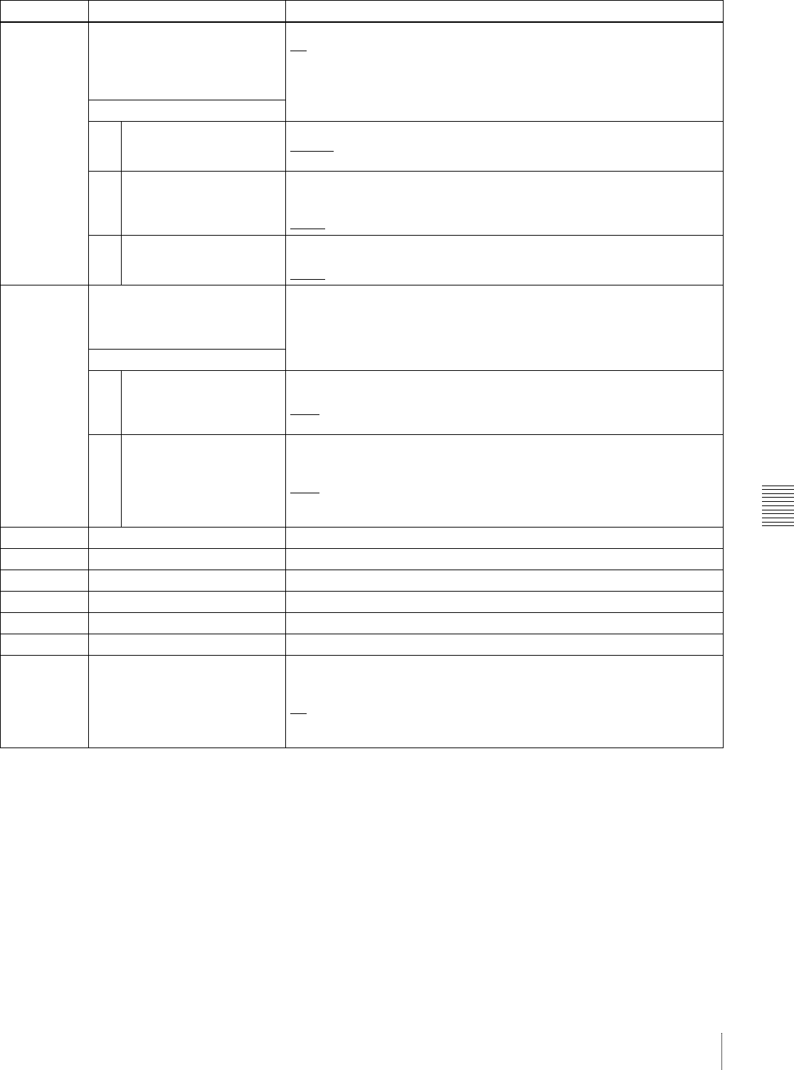
Chapter 7 Menus
93
7-2 Basic Setup Menu
a) This is supported from firmware version 1.5.
035 CLIP TITLE NAMING SELECT Specify whether or not to allow user definition of the titles assigned to clips.
off: Do not allow assignment.
on: Allow assignment.
See 6-1-3 “Assigning User-Defined Clip Titles” (page 75) for more
information about assigning titles.
Sub-item
1 TITLE Specify whether to assign titles to recorded clips.
disable: Do not assign titles to clips.
enable: Assign titles to clips.
2 PREFIX Set the prefix of the title (up to 10 characters). The allowable characters are
alphanumeric characters, symbols (! # $ % & ' ( ) + , - . ; = @ [ ] ^ _ { } ~), and
the space character.
TITLE
3 NUMERIC Set the initial value of the numeric part of the title (00001 to 99999, five-digit
number).
00001
036 FILE NAMING a) Specify whether to allow use of clip and clip list files with user-defined
names.
See 6-1-4 “Assigning User-Defined Clip and Clip List Names” (page 76) for
details about how to make the settings.
Sub-item
1 NAMING FORM Specify the clip and clip list naming format. (Specify whether to allow use of
files with user-defined names.)
C****: Standard format (Do not allow use of files with user-defined names)
free: Free format (Allow use of files with user-defined names)
2 AUTO NAMING When “free” is selected under the sub-item “NAMING FORM,” specify
whether to use the standard format name or the same name as the title for
clips recorded on this unit.
C****: Use the standard format for clip names.
title: Use the title set in basic menu item 035 “CLIP TITLE NAMING
SELECT” for clip names.
B01 RECALL SETUP BANK-1 Set to “on” to recall menu settings from menu bank 1.
B02 RECALL SETUP BANK-2 Set to “on” to recall menu settings from menu bank 2.
B03 RECALL SETUP BANK-3 Set to “on” to recall menu settings from menu bank 3.
B11 SAVE SETUP BANK-1 Set to “on” to save current menu settings to menu bank 1.
B12 SAVE SETUP BANK-2 Set to “on” to save current menu settings to menu bank 2.
B13 SAVE SETUP BANK-3 Set to “on” to save current menu settings to menu bank 3.
B20 RESET SETUP MENU Set to “on” to return the settings of the current menu to the factory default
settings. Set to “bank-4” to set the current menu to the settings saved in
menu bank 4.
off
on (on (default)): Return the current menu to the factory default settings.
bank-4: Set the current menu to the settings saved in menu bank 4.
Item number Item name Settings
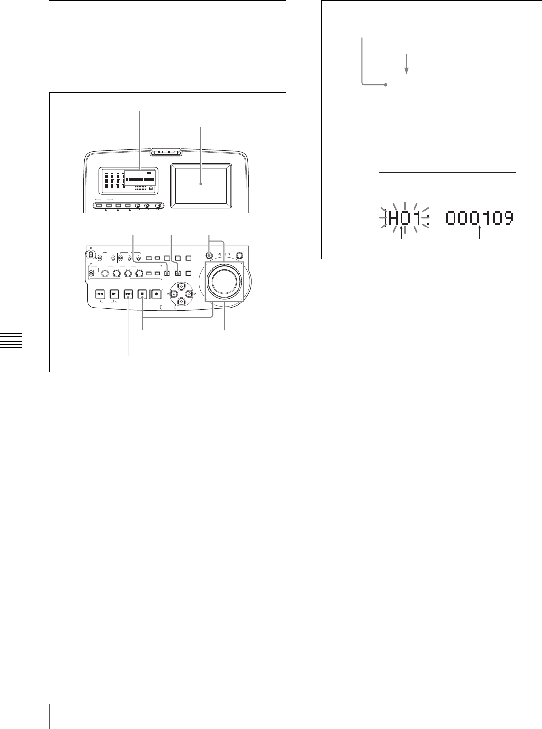
Chapter 7 Menus
94 7-2 Basic Setup Menu
7-2-2 Basic Menu Operations
Basic setup menu operations
This section explains how to select setup menu items and
how to change their values. The operations are common to
both the basic menu and the extended menu.
1
Press the MENU button.
The setup menu appears in the video panel, and on an
external monitor to which the output of the VIDEO
OUT 2 (SUPER)/SDI OUT (SUPER) connector is
input. A cursor indicates the currently selected menu
item.
The item number and current setting (elapsed time in
the case of the digital clock) of the currently selected
menu item also appear in the time data display section.
The item number flashes to indicate that you can
switch to another item.
To display the item name in the time data display
Hold down the NEXT button.
2
Rotate the jog dial or shuttle dial to select a menu item.
Rotate in the clockwise direction to select higher
numbers, and in the counterclockwise direction to
select lower number. The cursor moves in the direction
of the rotation (the screen scrolls when the cursor
reaches the top or bottom of the screen). The speed at
which the cursor moves and speed with which menu
items change vary with the rotation speed of the jog
dial or the rotation angle of the shuttle dial.
The STOP button lights when you select an item that
contains sub items.
3
When the selected item contains sub items, you can
select a sub item by holding down the STOP button
and rotating the jog dial or shuttle dial.
The displays in the video panel, on an external
monitor, and in the time data display section change as
shown below when you hold down the STOP button.
In the time data display section, the currently selected
sub item number flashes to indicate that you can
switch to another sub item.
AUDIO VIDEO
INPUT SEL
WARNING KEY INHI REC INHI
INPUT CH INPUT SEL STATUS LIGHT MONITOR
HLOFFOFF ON
OFF ON
-30
dB
-12
-20
-40
-60
0
CH
- 15
DATA
OVER
-30
dB
-12
-20
-40
-60
0
CH-
26
DATA
OVER
-30
dB
-12
-20
-40
-60
0
CH-
37
DATA
OVER
-30
dB
-12
-20
-40
-60
0
CH-
48 BATT E F
DATA
OVER
VITC
HOURS MINUTES SECONDS FRAMES
COUNTER HOLDVIUB
PB EXT-LKNDF
DISC E B
ACCESS
SHUTTLE JOG
THUMB
NAIL
ESSENCE
MARK
MENU
S.SEL
SET RESET
SHIFT
TOP F REV
ALL/CH-1 CH-2 CH-3 CH-4
TC
F FWD
AUDI O
END
REC
PRESET
VARIABLE
PB
PREV NEXTPLAY STOP REC
CLIP
MENU
SYSTEM
MENU
MONITOR
SEL
METER
SEL
HOLD
COUNTER
SEL
SUB
CLIP
MARK1
MARK2
IN OUT
KEY INHI
ON
OFF
NETWORK
LOCAL
REMOTE
F-RUN
R-RUN
PRESET
REGEN
INT
EXT
RP188
L/ST/R
CHARACTER
VITC
PROCESS
CONTROL
23
4
1,5 5
Video panel
Time data display
NEXT button
*HO1 : OPE HOURS - 109
HOUR METER
H11 : OPE HOURS r- 109
-------
Group name for the currently selected item
Cursor indicating the currently selected item
Item number (flashing)
Display in time data display
Display in video panel and on external monitor
Setting
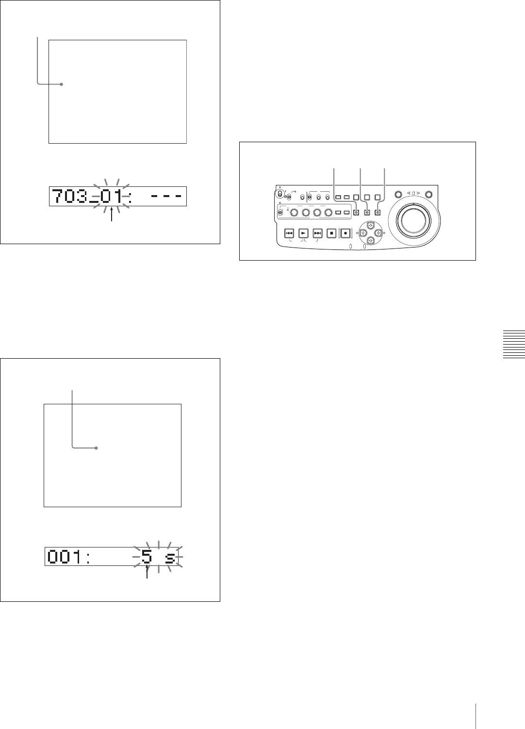
Chapter 7 Menus
95
7-2 Basic Setup Menu
4
With the SHUTTLE button held down, rotate the jog
dial or shuttle dial to change the setting.
The displays in the video panel, on an external
monitor, and in the time data display section change as
shown below when you hold down the SHUTTLE
button. In the time data display section, the currently
selected setting value flashes to indicate that you can
change it to another value.
5
Press the SET button.
This saves the new setting value, and the menu display
disappears from the video panel, the external monitor,
and the time data display section.
To abandon making a change
Press the MENU button before pressing the SET
button.
The menu display disappears from the video panel, the
external monitor, and the time data display section
without the new setting value being saved.
Resetting the menu settings to their
factory default values
To reset the current active menu settings to their factory
default values, proceed as follows.
1
Press the MENU button.
The menu appears in the video panel, on an external
monitor to which the output of the VIDEO OUT 2
(SUPER)/SDI OUT (SUPER) connector is input, and
in the time data display section.
2
Press the RESET button.
The message “INITIALIZE ALL ITEMS TO
FACTORY PRESET VALUES?” appears in the video
panel and on the external monitor.
The message “Init setup?” appears in the time data
display.
To abandon operations and return to the setup
menu display
Press the RESET button again.
3
Press the SET button.
The menu settings are reset to their factory default
settings.
Switching between 525(U) line, 525(J) line
and 625 line modes (menu item 013)
To switch between 525(U) line, 525(J) line and 625 line
operation modes, proceed as follows.
1
Press the MENU button.
2
Turn the jog dial or shuttle dial to display menu item
013 in the time data display.
BLANK LINE SELECT
ITEM-703
* ALL LINE - ---
LINE 12 - blnk
----
Cursor indicating the currently selected sub-item
Sub-item number (flashing while changing)
Display in time data display
Display in video panel and on external monitor
ITEM-001
5 sec
PREROLL TIME
Setting value
Setting value (flashing while changing)
Display in time data display
Display in video panel and on external monitor
ACCESS
SHUTTLE JOG
THUMB
NAIL
ESSENCE
MARK
MENU
S.SEL
SET RESET
SHIFT
TOP F REV
ALL/CH-1 CH-2 CH-3 CH-4
TC
F FWD
AUDI O
END
REC
PRESET
VARIABLE
PB
PREV NEXTPLAY STOP REC
CLIP
MENU
SYSTEM
MENU
MONITOR
SEL
METER
SEL
HOLD
COUNTER
SEL
SUB
CLIP
MARK1
MARK2
IN OUT
KEY INHI
ON
OFF
NETWORK
LOCAL
REMOTE
F-RUN
R-RUN
PRESET
REGEN
INT
EXT
RP188
L/ST/R
132
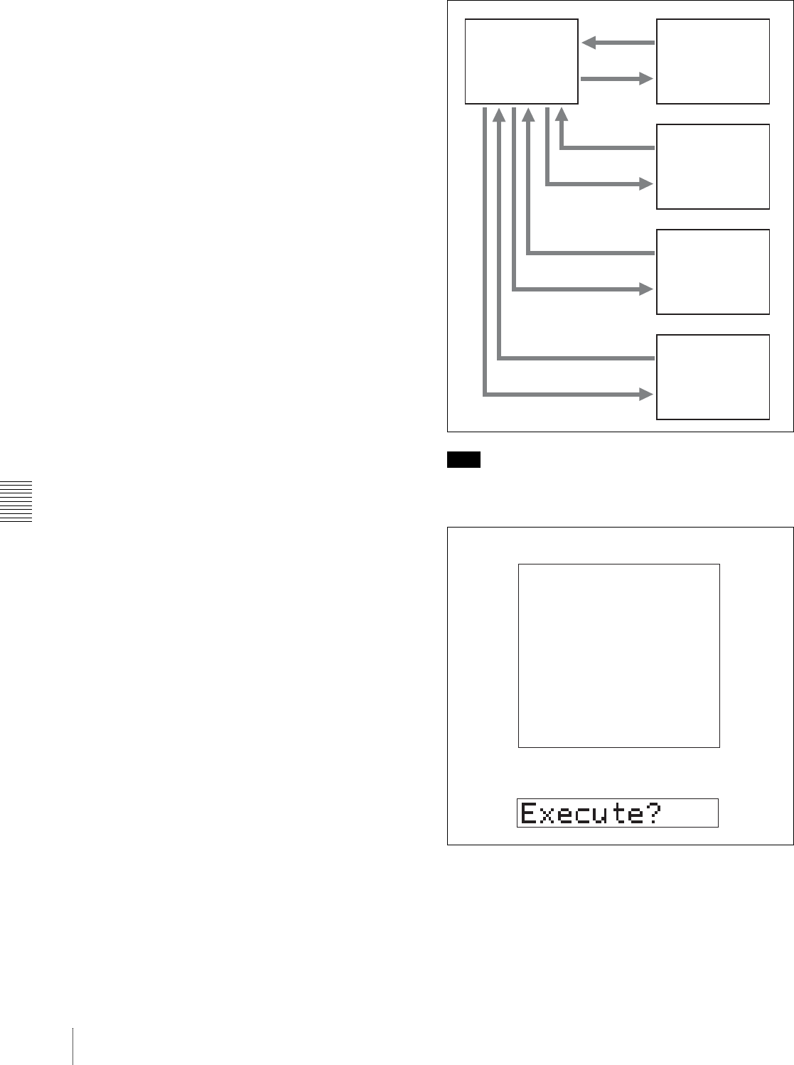
Chapter 7 Menus
96 7-2 Basic Setup Menu
3
Hold down the SHUTTLE button, and turn the jog dial
or shuttle dial to set menu item 013 to “on.”
4
Press the SET button.
5
Hold down the SHUTTLE button, and turn the jog dial
or shuttle dial to select the line mode 525(U), 525(J) or
625.
6
Press the SET button.
7
Turn the unit off (press the on/standby switch to put
the unit in the standby state).
Next time the unit is turned on (when the unit is put in the
operating state by pressing the on/standby switch), it
operates in the new mode.
Menu bank operations (menu items B01 to
B13)
This unit allows menu settings to be saved in what are
termed “menu banks.” Saved sets of menu settings can be
recalled for use as required.
To jump to menu item B01
You can recall any required menu by turning the jog dial
or shuttle dial after pressing the MENU button.
If you press the MENU button first, then the COUNTER
SEL button, you can jump directly to menu item B01 or
H01. The recalled menu item toggles between B01 and
H01 every time you press the COUNTER SEL button.
Saving the current active menu settings
Set one of basic menu items B11 “SAVE SETUP BANK-
1” to B13 “SAVE SETUP BANK-3” to “on,” depending
on which of the menu banks you wish to save in, then press
the SET button.
Recalling settings from a menu bank
Set one of basic menu items B01 “RECALL SETUP
BANK-1” to B03 “RECALL SETUP BANK-3” to “on,”
depending on which of the menu banks you wish to recall
from, then press the SET button.
To recall menu bank 4, select “bank-4” under menu item
B20 “RESET SETUP MENU.”
Refer to the maintenance manual for more information
about menu bank 4.
Note
The following message appears if the line mode of the
menu bank that you are about to recall differs from the
current line mode.
Press the SET button to recall the settings and switch to the
line mode saved in the menu bank. When you power the
unit off and then on again, it will use the line mode and
settings of the selected bank.
To cancel the recall, press the MENU button.
Current active
menu settings Menu bank 1
Menu bank 2
Menu bank 3
Recall
Save
Recall
Save
Recall
Save
Menu bank 4
Recall
Save
RECALL SETUP BANK-1
System will be changed.
Are you sure you want
to execute?
EXECUTE : SET KEY
ABORT : MENU KEY
ITEM-B01
Message in time data display
Display in the video panel and on an external monitor

Chapter 7 Menus
97
7-3 Extended Menu
7-3 Extended Menu
7-3-1 Items in the Extended Menu
The following tables show the items in the extended menu.
• Item names are the names which appear in the video
panel, and on an external monitor to which the output of
the VIDEO OUT 2 (SUPER)/SDI OUT (SUPER)
connector is input.
An abbreviated name appears in the time data display
section when you press the NEXT button.
• The values in the Settings columns are the values which
appear in the time data display section. (The values may
appear in a different format in the video panel and on an
external monitor. In this case, the video panel values are
shown in parentheses.) Underlined values are the factory
defaults.
Menu items in the 100s, relating to the control panels
Item number Item name Settings
101 SELECTION FOR SEARCH DIAL
ENABLE Select how the unit enters the shuttle or jog mode.
dial (dial direct): Press the SHUTTLE or JOG button or, except during
recording/editing, turn the jog dial or shuttle dial.
key (via search key): Press the SHUTTLE or JOG button.
105 REFERENCE SYSTEM ALARM Select whether or not to display a warning when the reference video
signal is not supplied or is out of phase with the input video signal.
off: No warning.
on: Flash the STOP button as a warning.
107 REC INHIBIT LAMP FLASHING Select whether or not to flash the REC INHI indicator when recording is
prevented (see “REC INHI (recording inhibited) indicator” on page 18).
off: Light the REC INHI indicator.
on: Flash the REC INHI indicator.
108 AUTO EE SELECT When a disc is inserted, select the operation modes in which input video
and audio signals are automatically handled in E-E mode.
S/F/R (stop/f.fwd/f.rev): In stop/fast-forward/fast-reverse modes
stop: In stop mode
off: Do not put the unit into E-E mode automatically.
109 FORCED EE WHEN DISC UNLOAD When “off” is selected in menu item 108, during disc loading/unloading
and when no disc is inserted, select whether or not to control the output
signal PB/EE setting.
on: Do not control (the signal is always an E-E signal).
off: Control.
114 AUDIO MONITOR OUTPUT LEVEL When “moni” is selected in menu item 820, select whether or not to
control the level of the audio signal output from the AUDIO OUT 1/3, 2/4
connectors with the volume control knob for the PHONES jack.
var (variable): Control.
fixed: Do not control.
118 KEY INHIBIT When the KEY INHI switch is set to ON, select which buttons can be
operated. The following sub-items control different sets of buttons
independently.
Sub-item
1 MON./INPUT SEL Select whether the AUDIO MONITOR SEL, the AUDIO METER SEL, the
AUDIO INPUT CH, and the VIDEO INPUT SEL buttons are enabled.
dis: Disabled.
ena: Enabled.
2 CONTROL PANEL Select whether all switches and buttons other than the buttons specified
with sub-item 1 and the MENU button are enabled.
dis: Disabled.
ena: Enabled.
121 FRAME PB MODE Specify the frame mode for variable speed playback.
field: Field playback
frame: Frame playback. Compared to field playback, frame playback
gives still pictures with higher precision.
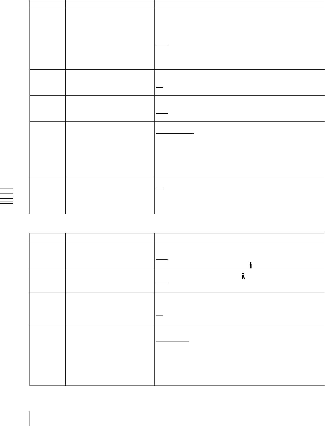
Chapter 7 Menus
98 7-3 Extended Menu
131 AUDIO VOLUME Select whether each of the ALL/CH-1, CH-2 to CH-4 adjustment knobs
on the control panel is effective to control the audio recording level and
playback level on each channel or the ALL/CH-1 adjustment knob alone
functions as a master control to control the audio level on all channels
together.
each: Each of the ALL/CH-1, CH-2 to CH-4 adjustment knobs is effective
to control each channel.
all: The ALL/CH-1 adjustment knob alone functions as a master control.
When “all” is selected, the ALL indicator to the right of the ALL/CH-1
adjustment knob lights up.
142 REPEAT MODE Put the unit into repeat playback mode, or exit from repeat playback
mode.
off: Exits from repeat playback mode.
play: Puts the unit into repeat playback mode.
143 INDEX PICTURE POSITION Select the frame of the clip to use as the thumbnail image (index picture)
when recording.
0sec to 10sec: Can be set in the range from 0 seconds (first frame of the
clip) to10 seconds, in units of 1 second.
145 MODE KEY ENABLE DURING
RECORDING Specify whether only the STOP button stops recording.
ena (all enable): Recording stops when the EJECT button is pressed a)
and when the PLAY, STOP, SHUTTLE, and JOG buttons are
pressed. b)
stop: Recording stops only when the STOP button is pressed.
a) The disc is ejected after recording stops.
b) The unit enters stop mode when the PLAY button is pressed, and enters still
image mode (jog/shuttle mode) when the SHUTTLE or JOG button is pressed.
146 POWER SAVE MODE Specifies whether to put the unit into power save mode.
off: Do not put the unit into power save mode.
on: Put the unit into power save mode. The following operations take
slightly longer to start in power save mode.
• Recording, playback, jog and shuttle mode playback, search
• Display of the thumbnail screen and essence marks
Menu items in the 100s, relating to the control panels
Item number Item name Settings
Menu items in the 200s, relating to the remote control interface
Item number Item name Settings
214 REMOTE INTERFACE When the remote control switch is set to REMOTE, select the device from
which to remote-control this unit.
9PIN: Device connected to the REMOTE connector.
i.LNK (i.LINK): Device connected to the S400 (i.LINK) connector.
215 i.LINK MODE Select the connection method for the S400 (i.LINK) connector.
AV/C: Connect with AV/C.
FAM (FAM (PC REMOTE)): Connect with FAM.
216 PARALLEL RECORDING MODE Specifies whether recording of video and audio on this unit should start
and stop at the same time as recording on a camcorder connected to this
unit by i.LINK(AV/C).
off: Do not conduct parallel recording.
on: Conduct parallel recording.
257 NETWORK ENABLE Select the remote control switch positions which enable network
connections.
net (network): Only when the switch is set to “NETWORK.”
n&9P (network & remote(9PIN)): When the switch is set to
“NETWORK,” and when the switch is set to “REMOTE” and extended
menu item 214 is set to “9PIN.” a)
a) FTP connections can be made only when the device connected to the REMOTE
connector (D-sub 9 pin) is in stop mode. During FTP connections, the device
connected to the REMOTE connector cannot be used to control this unit.
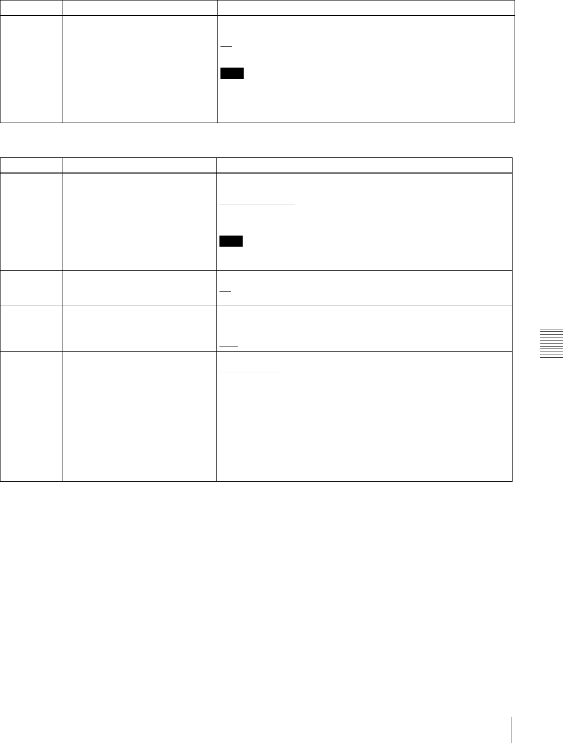
Chapter 7 Menus
99
7-3 Extended Menu
258 LIVE LOGGING Enable or disable the live logging function when using the PDZ-1 Proxy
Browsing Software.
off: Disable.
on: Enable.
Note
During live logging, regardless of the settings of the switches (INT/EXT/
RP188, PRESET/REGEN, and F-RUN/R-RUN) in the time data settings
section, the internal time code generator always runs in free run mode.
Time code cannot be recorded in internal preset mode.
Menu items in the 200s, relating to the remote control interface
Item number Item name Settings
Menu items in the 300s, relating to editing operations
Item number Item name Settings
308 SELECTION OF STD/NON-STD
FOR COMPOSITE VIDEO IN Select the STD or NON-STD mode in accordance with a composite
video or S-video input.
STD (forced STD): The STD mode is always used (forced STD mode).
N-STD (forced non-STD): Use this setting when the input video signal is
unstable (forced NON-STD mode).
Note
When using a VCR with no built-in time base corrector (e.g. a home-use
VHS-system VCR), select N-STD.
310 REC INHIBIT Select whether recording is inhibited.
off: Do not inhibit recording.
on: Inhibit recording.
320 DIGITAL AUDIO PB PROCESS ON
EDIT POINT Select the treatment of audio playback at edit points.
cut: Carry out a cut (possibly resulting in audio discontinuities at the edit
point).
fade: Fade out and fade in.
335 OUTPUT REFERENCE SEL Select the reference signal of this unit.
ref (ref. video): Use the signal input to the REF VIDEO IN connector as
the reference signal.
auto: According to the operation mode, automatically select either the
signal input to the REF VIDEO IN connector or the input video signal
selected with the VIDEO INPUT SEL button as the reference signal.
For more details, see the following item “External synchronization to
reference signal generators” (page 100).
The input digital audio signals and video signals must be synchronized
with the reference signal input to the REF VIDEO IN connector.
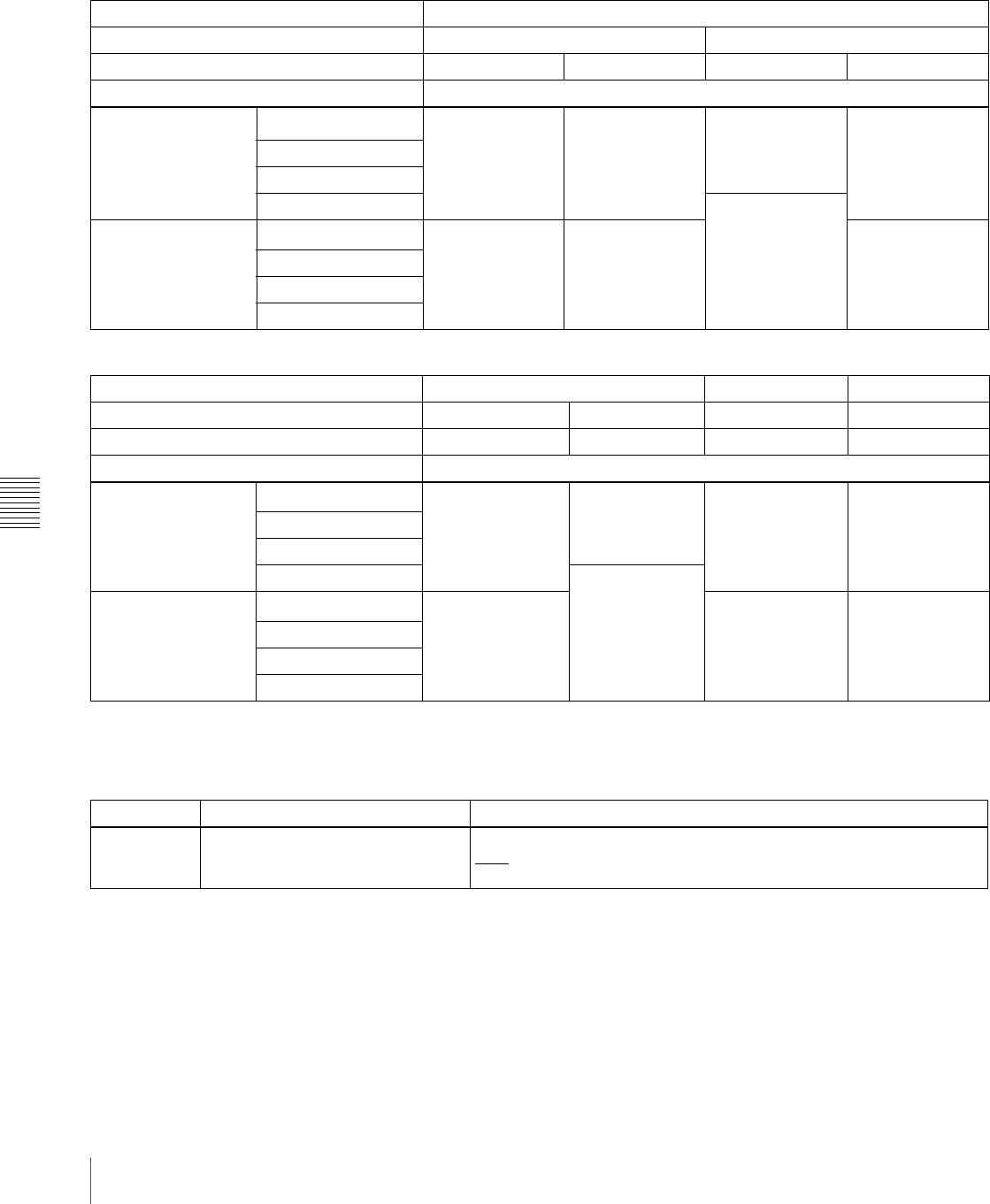
Chapter 7 Menus
100 7-3 Extended Menu
External synchronization to reference signal generators
The internal reference signal generator is synchronized
either to a reference signal input to the REF VIDEO IN
connector or an input video signal. Depending on the
settings of extended menu items 335 and 308, and the input
signal selection, the external synchronization status is as
shown in the following table.
The video signals are output always synchronized to the
internal reference signal.
a) Synchronize to the reference signal input to the REF VIDEO IN connector.
b) Synchronize to the signal input to the VIDEO IN connector. If no signal is
input to the connector, no synchronization is made.
c) Synchronize to the signal input to the SDI IN connector. If no signal is
input to the connector, no synchronization is made.
d) No external synchronization is made.
VIDEO INPUT SEL button setting COMPOSITE
Item 335 setting ref auto
Item 308 setting STD N-STD STD N-STD
Operation mode External synchronization status
When a signal is input
to the REF VIDEO IN
connector
E-E mode REF a) REF a) REF a) REF a)
Normal playback
REC button pressed
Recording INPUT/Free b)
When no signal is
input to the REF
VIDEO IN connector
E-E mode INPUT/Free b) Free RUN d) Free RUN d)
Normal playback
REC button pressed
Recording
VIDEO INPUT SEL button setting SDI i.LINK SG
Item 335 setting ref auto ref/auto ref/auto
Item 308 setting STD/N-STD STD/N-STD STD/N-STD STD/N-STD
Operation mode External synchronization status
When a signal is input
to the REF VIDEO IN
connector
E-E mode REF a) REF a) REF a) REF a)
Normal playback
REC button pressed
Recording SDI IN/Free c)
When no signal is
input to the REF
VIDEO IN connector
E-E mode SDI IN/Free c) Free RUN d) Free RUN d)
Normal playback
REC button pressed
Recording
Menu items in the 400s, relating to preroll
Item number Item name Settings
401 FUNCTION MODE AFTER CUE-UP Select the state that the unit goes into after a cuing-up operation.
stop: Stops (the stop mode).
still: Still playback (in jog and shuttle mode).
Chapter 7 Menus
101
7-3 Extended Menu
Menu items in the 500s, relating to disc protection
Item number Item name Settings
501 STILL TIMER To protect the disc against shock and vibrations, and to lengthen the life
of the laser diodes, the unit automatically enters standby off mode
whenever a specified time elapses in a disc stop mode (stop mode or the
still picture mode of search mode). This allows you to set the time after
which the unit exits a disc stop mode and enters standby off mode.
0.5 s (0.5 sec)... 8 m (8 min)... 30 m (30 min): Can be set in the range
from 0.5 seconds to 30 minutes.
off: Do not put into standby off mode.
Menu items in the 600s, relating to the time code, metadata, and UMID
Item number Item name Settings
601 VITC POSITION SEL-1 Select a line into which to insert VITC signals for IMX recording signals a)
and DVCAM playback signals. b)
12 H (12 line)... 16 H (16 line)... 20 H (20 line) (in 525(U)/525(J) line
modes)
9 H (9 line)... 19 H (19 line)... 22 H (22 line) (in 625 line mode)
Note
You can insert the VITC signal in two places. To insert it in two places,
set both items 601 and 602.
a) In the IMX format, VITC is inserted as video signals in vertical blanking sections.
Because these signals are output as video signals during playback, the insertion
line can be specified only for recording.
b) In the DVCAM format, VITC is recorded as VAUX (Video Auxiliary) data.
Because VITC is inserted into video signals by the VITC generator only during
playback, the insertion line can be specified only for playback.
602 VITC POSITION SEL-2 Select a line into which to insert VITC signals for IMX recording signals a)
and DVCAM playback signals. b)
12 H (12 line)... 18 H (18 line)... 20 H (20 line) (in 525(U)/525(J) line
modes)
9 H (9 line)... 21 H (21 line)... 22 H (22 line) (in 625 line mode)
Note
You can insert the VITC signal in two places. To insert it in two places,
set both items 601 and 602.
a) In the IMX format, VITC is inserted as video signals in vertical blanking sections.
Because these signals are output as video signals during playback, the insertion
line can be specified only for recording.
b) In the DVCAM format, VITC is recorded as VAUX (Video Auxiliary) data.
Because VITC is inserted into video signals by the VITC generator only during
playback, the insertion line can be specified only for playback.
605 TCG REGEN MODE Select the signal to be regenerated when the time code generator is in
the regeneration mode (i.e., when the PRESET/REGEN switch is set to
REGEN).
TC&UB: Both the time code and user bits are regenerated.
TC: Only the time code is regenerated.
UB: Only the user bits are regenerated.
607 U-BIT BINARY GROUP FLAG Select the user bits to be used in the time code generated by the time
code generator.
000 (000:not specified): Character set not specified.
001 (001:iso character): 8-bit characters compliant with ISO 646 and
ISO 2022.
010 (010:unassigned-1): Undefined.
011 (011:unassigned-2): Undefined.
100 (100:unassigned-3): Undefined.
101 (101:page / line): SMPTE 262M page/line multiplex system.
110 (110:unassigned-4): Undefined.
111 (111:unassigned-5): Undefined.

Chapter 7 Menus
102 7-3 Extended Menu
611 TC OUTPUT PHASE IN EE MODE Select the time code output mode for output from the TC OUT connector
in E-E mode.
mutng (muting): Suppress the output.
thru (through): Output the time code input to the TC IN connector as it
is.
v-in (video input phase): Output the time code with the same phase as
the input video signal phase.
v-out (video output phase): Output the time code with the same phase
as the output video signal phase.
612 TC OUTPUT MUTING IN SEARCH
MODE Select whether to suppress the output from the TC OUT connector in jog/
shuttle mode.
on: Suppress.
off: Do not suppress.
619 VITC Specify whether or not to record the VITC generated by the internal time
code generator.
off: Do not record internally generated VITC.
on: Record internally generated VITC.
Note
Even if this item is set to “off,” VITC is recorded if the input video signal
contains VITC and the VITC line is set to “thru” with item 723.
628 DF MODE In 525(U)/525(J) line modes, when the INT/EXT/RP188 switch is set to
INT and the PRESET/REGEN switch is set to PRESET, select the frame
mode of the internal time code generator and counter.
df (on (df)): Drop-frame mode
ndf (off (ndf)): Non-drop frame mode
629 TC SELECT Select the type of time data to show in the time data display, and the type
of external time code when the INT/EXT/RP188 switch is set to EXT and
the PRESET/REGEN switch is set to REGEN.
vitc: Display time code as VITC, or select VITC as the external time
code.
tc: Display time code as TC, or select TC as the external time code.
See 4-1-2 “Recording Time Code and User Bit Values” (page 44) for
more information about selecting external time code.
632 TC UBIT SELECT When item 629 is set to “tc,” specify whether to synchronize the user bits
of the time code generator to the internal clock.
fix: Do not synchronize user bits.
time: Synchronize user bits to the internal clock.
633 VITC UBIT SELECT When item 629 is set to “vitc,” specify whether to synchronize the user
bits of the time code generator to the internal clock.
fix: Do not synchronize user bits.
time: Synchronize user bits to the internal clock.
634 WATCH AUTO ADJUST When external time code input contains real-time clock user bits, specify
whether to adjust the internal clock to match the real-time clock.
off: Do not adjust the internal clock to match the real-time clock.
on: Adjust the internal clock to match the real-time clock.
651 UMID SDI OUTPUT Select whether to output UMID in the VANC of the SDI output.
off: Do not output.
on: Output.
See 7-3-3 “Using UMID Data” (page 109) for more information about
UMID.
Menu items in the 600s, relating to the time code, metadata, and UMID
Item number Item name Settings

Chapter 7 Menus
103
7-3 Extended Menu
652 UMID SDI VANC LINE Select the line in which UMID is output when menu item 651 is set to
“on.”
12 H (12 line), 13 H (13 line), 15 H (15 line), 16 H (16 line), 17 H (17
line), 18 H (18 line), 19 H (19 line) (525(U)/525(J) line modes)
9 H (9 line), 10 H (10 line), 12 H (12 line), 13 H (13 line), 14 H (14 line),
15 H (15 line), 16 H (16 line), 17 H (17 line), 18 H (18 line) (625
line mode)
See 7-3-3 “Using UMID Data” (page 109) for more information about
UMID.
657 ESSENCE MARK SDI OUTPUT Select whether to output essence marks in the SDI output VANC.
off: Do not output.
on: Output.
660 ESSENCE MARK SDI VANC LINE When item 657 is set to “on,” select the line to which to output essence
marks.
12 H (12 line), 13 H (13 line), 15 H (15 line), 16 H (16 line), 17 H (17
line), 18 H (18 line), 19 H (19 line) (525(U)/525(J) line modes)
9 H (9 line), 10 H (10 line), 12 H (12 line), 13 H (13 line), 14 H (14 line),
15 H (15 line), 16 H (16 line), 17 H (17 line), 18 H (18 line) (625
line mode)
Menu items in the 600s, relating to the time code, metadata, and UMID
Item number Item name Settings
Menu items in the 700s, relating to video control
Item
number
Item name Settings
701 SELECTION OF VIDEO/SYNC
DELAY An E-E video signal is output delayed with respect to the video input signal by
the time for video circuit processing.
With this item, select whether or not to delay the sync signal attached to the
output video signal by an amount corresponding to the video signal delay.
sync (sync delay): Delay the sync signal by the corresponding amount
before attaching it.
video (video delay): Attach a sync signal with the same timing as the input
signal.
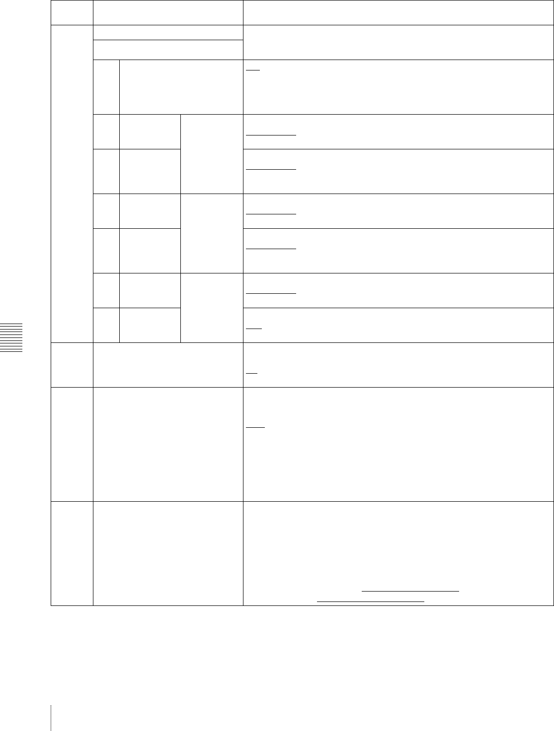
Chapter 7 Menus
104 7-3 Extended Menu
703 BLANK LINE SELECT Switch blanking of the video output signal on or off for individual lines in the
vertical blanking interval.
The Y/C signal and odd/even fields are blanked simultaneously.
Sub-item
1ALL LINE - - -: Specify the blanking for each line separately.
blnk (blank): Regardless of the setting of other sub-items, blank all lines
which can be specified in this menu item.
thru (throu): Regardless of the setting of other sub-items, switch off blanking
for all lines which can be specified in this menu item.
2 ...
9LINE 12 ...
LINE 19 In 525(U) line
mode Specify blanking for lines 12 to 19.
blnk (blank): Carry out blanking.
thru (throu): Switch off blanking.
10 LINE 20 Specify blanking for line 20.
blnk (blank): Carry out blanking.
half: Carry out half-blanking.
thru (throu): Switch off blanking.
2 ...
10 LINE 12 ...
LINE 20 In 525(J) line
mode Specify blanking for lines 12 to 20.
blnk (blank): Carry out blanking.
thru (throu): Switch off blanking.
11 LINE 21 Specify blanking for line 21.
blnk (blank): Carry out blanking.
half: Carry out half-blanking.
thru (throu): Switch off blanking.
2 ...
15 LINE 9, 322
... LINE 22,
335
In 625 line
mode Specify blanking for lines 9, 322 to 22, 335.
blnk (blank): Carry out blanking.
thru (throu): Switch off blanking.
16 LINE 23 Specify blanking for line 23.
half: Carry out half-blanking.
thru (throu): Switch off blanking.
705 EDGE SUBCARRIER REDUCER
MODE Select whether to enable the edge subcarrier reducer (ESR).
on: Enable.
off: Do not enable.
When playing back a composite signal, set this to “on.”
707 FORCED VERTICAL
INTERPOLATION OFF The “Y-add” function is normally switched on automatically during jog or
variable speed playback. This item selects whether or not to force the “Y-add”
function off.
auto: Automatically switch the “Y-add” function on.
off (forced YADD off): Force the “Y-add” function off.
The “Y-add” function is off while a disc image is displayed in stop mode (menu
item 108 “AUTO EE SELECT” is “off”).
The “Y-add” function is a circuit operation to interpolate the video signal
vertically during jog or variable speed playback for the purpose of reducing
the vertical movement of the playback picture.
710 INTERNAL VIDEO SIGNAL
GENERATOR Select the test signal to be output from the internal test signal generator.
When “SG” is selected using the VIDEO INPUT SEL button, the internal test
signal generator operates to output the selected test signal. This signal can
also be recorded.
BB (Black Burst): Black burst signal
CB75 (75% Color Bars): 75% color bar signal
CB100 (100% Color Bars): 100% color bar signal
The factory default settings for each line mode are as follows:
In 525(U)/525(J) line modes: CB75 (75% Color Bars)
In 625 line mode: CB100 (100% Color Bars)
Menu items in the 700s, relating to video control
Item
number
Item name Settings
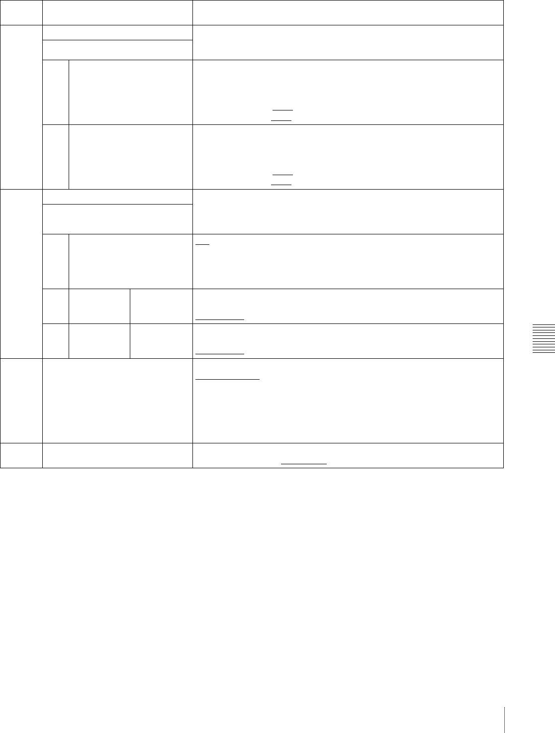
Chapter 7 Menus
105
7-3 Extended Menu
713 VIDEO SETUP REFERENCE Select whether to remove the setup (7.5%) from the input analog video
signals and whether to add the setup (7.5%) to the output analog video
signals (when 525(U) or 525(J) line mode is selected).
Sub-item
1 INPUT LEVEL Whether to remove the setup (7.5%) from the input analog video signals.
0.0%: Do not remove.
7.5%: Remove.
The factory default settings for each line mode are as follows:
525(U) line mode: 7.5%
525(J) line mode: 0.0%
2 OUTPUT LEVEL Whether to add the setup (7.5%) to the output analog video signals.
0.0%: Do not add.
7.5%: Add.
The factory default settings for each line mode are as follows:
525(U) line mode: 7.5%
525(J) line mode: 0.0%
723 INPUT VIDEO BLANK Switch blanking on or off for individual lines in the vertical blanking interval of
an input video signal. The Y/C signal and odd/even fields are blanked
simultaneously.
A signal with blanking carried out according to this setting is recorded.
Sub-item
1ALL LINE - - -: Specify the blanking for each line separately.
blnk (blank): Regardless of the setting of other sub-items, blank all lines
which can be specified in this menu item.
thru (throu): Regardless of the setting of other sub-items, switch off blanking
for all lines which can be specified in this menu item.
2 ...
10 LINE 12 ...
LINE 20 In 525(U)/
525(J) line
modes
Specify blanking for lines 12 to 20.
blnk (blank): Carry out blanking.
thru (throu): Switch off blanking.
2 ...
15 LINE 9, 322
...
LINE 22, 335
In 625 line
mode Specify blanking for lines 9, 322 to 22, 335.
blnk (blank): Carry out blanking.
thru (throu): Switch off blanking.
726 H BLANKING WIDTH Select the horizontal blanking width of the output analog video signal.
narow (narrow): Digital blanking (narrow)
wide: Analog blanking (wide)
When “wide” is selected, the horizontal blanking width complies with RS170A,
and normally the blanking is widened and the image becomes narrower. It is
recommended to select “narow” at the editing stage, then later, for broadcast
transmission to select “wide,” to output a signal conforming to the standard.
Note, however, that “narow” has to be always selected for SDI signals.
728 OUTPUT SCH PHASE Set the subcarrier H phase.
–512 (–512 (DEC))... 0 (0 (DEC))... 511 (511 (DEC))
Menu items in the 700s, relating to video control
Item
number
Item name Settings
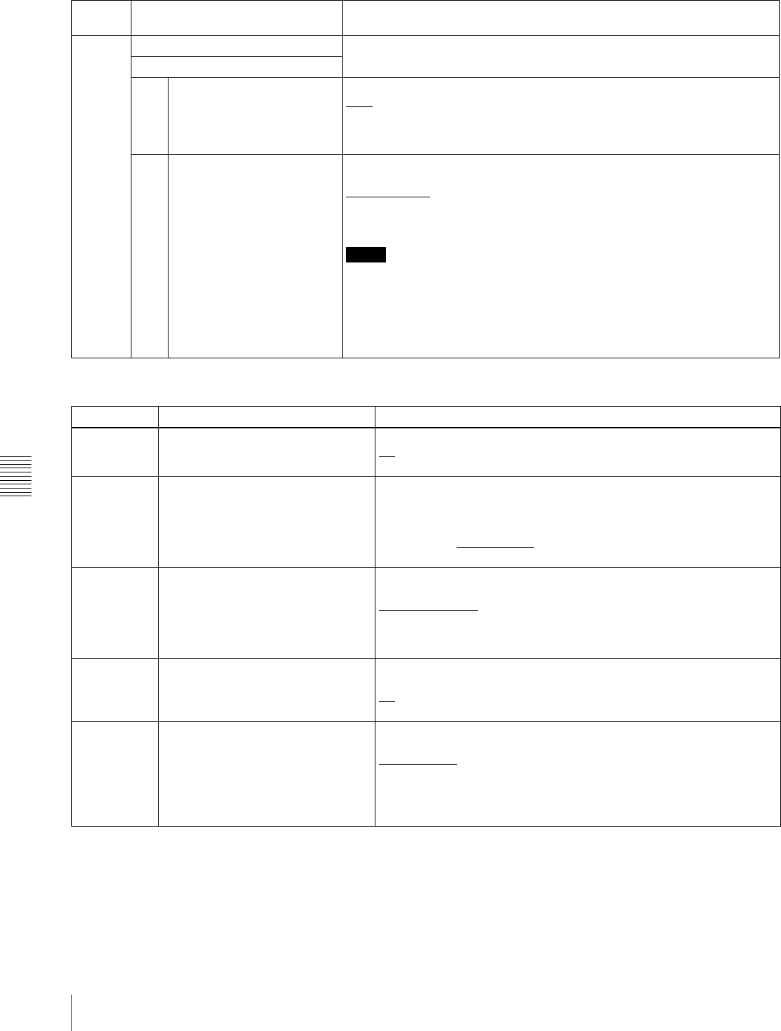
Chapter 7 Menus
106 7-3 Extended Menu
731 WIDE MODE Specify whether to record and play back with the addition of wide picture
information.
Sub-item
1 INPUT Specify whether to save wide picture information on a disc during recording.
auto: Automatically record wide picture information when it is detected in the
selected input video signal.
on: Always record wide picture information.
off: Do not record wide picture information.
2 OUTPUT Specify whether to add wide picture information to the output signal during
MPEG IMX playback.
thru (through): Output the video signals of the disc being played back
without adding wide picture information.
auto: When wide picture information is detected on the disc being played
back, add wide picture information to the output video signals.
Notes
• To add wide picture information to the output signal, it is necessary, in
addition to setting this item to “thru,” to operate extended menu item 703 to
set line 20 (in 525 line mode) to “thru” or set line 23 (in 625 line mode) to
“thru.”
• In 525 line mode, wide picture information may not be output if VITC signal
insertion position is set to line 20 in extended menu item 601 or 602.
Menu items in the 700s, relating to video control
Item
number
Item name Settings
Menu items in the 800s, relating to audio control
Item number Item name Settings
802 DIGITAL AUDIO MUTING IN
SHUTTLE MODE Set the audio muting conditions during shuttle playback.
off: Not muted.
on: Muted.
807 AUDIO OUTPUT PHASE Set the output timing of digital audio playback signals (SDI, AES/EBU
only), with 80H as a reference position. Output timing is earlier for
values smaller than 80H and later for values greater than 80H. (80H,
128 samples = approx. 2.7 ms, 80H, 1 sample = approx. 20 μs)
0 (0 (HEX))... 80 (80 (HEX))... FF (FF (HEX)): Values can be set in this
range.
808 INTERNAL AUDIO SIGNAL
GENERATOR Select the operation of the internal audio test signal generator.
silnc (silence): Silent signal.
1kHz (1kHz sine): 1 kHz, –20 dB FS sine wave signal.
When you select SG as the audio input in the input selection section of
the control panel, the audio test signal generated by the internal audio
test signal generator is input.
815 AUDIO SAMPLING RATE
CONVERTER Select the mode of operation of the sampling rate converter for AES/
EBU input to channels 1 to 4.
off: Do not operate.
on: Operate.
820 AUDIO OUTPUT CH1/CH2 SELECT Select the signals to be output from the AUDIO OUT 1/3 and AUDIO
OUT 2/4 connectors.
line (line out): Output the audio channel signals selected with item 824
“just as they are” from the AUDIO OUT 1/3 and 2/4 connectors.
moni (monitor out): Output the monitor audio L-channel (CH-1) and
monitor audio R-channel (CH-2) signals from the AUDIO OUT 1/3 and
AUDIO OUT 2/4 connectors, respectively.
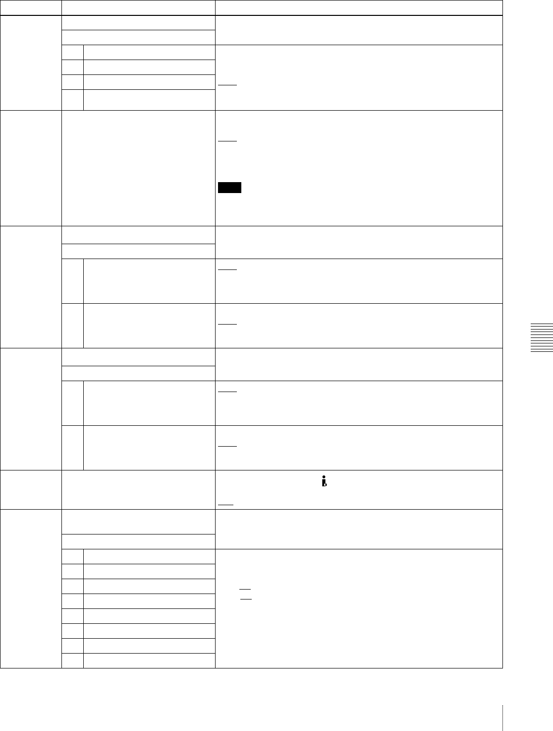
Chapter 7 Menus
107
7-3 Extended Menu
823 NON-AUDIO FLAG PB Control non-audio flags in digital audio output.
Sub-item
1 CH1/CH2 During playback (except E-E mode), set non-audio flags in digital audio
output to the following states.
on: Set to on (data is non-audio)
auto: Set as follows.
• When data is read from disc and confirmed: Follow the data.
• When data from disc is not confirmed: Maintain current state.
2 CH3/CH4
3 CH5/CH6
4 CH7/CH8
824 ANALOG LINE OUTPUT SELECT Select the analog audio signals (tracks 1 to 8) to be assigned to audio
output channels 1 and 2.
tr1/2: Tracks 1 and 2 assigned to audio output channels 1 and 2.
tr3/4: Tracks 3 and 4 assigned to audio output channels 1 and 2.
tr5/6: Tracks 5 and 6 assigned to audio output channels 1 and 2.
tr7/8: Tracks 7 and 8 assigned to audio output channels 1 and 2.
Note
When item 820 is set to “moni,” the left channel (CH-1) and right
channel (CH-2) of monitor audio are output from the AUDIO OUT 1/3
and 2/4 connectors respectively, regardless of the setting of this item.
827 AES/EBU AUDIO OUTPUT SELECT Select the audio signals to assign to AES/EBU audio output channels.
Sub-item
1 CH1/CH2 tr1/2: Tracks 1 and 2 assigned to audio output channels 1 and 2.
tr3/4: Tracks 3 and 4 assigned to audio output channels 1 and 2.
tr5/6: Tracks 5 and 6 assigned to audio output channels 1 and 2.
tr7/8: Tracks 7 and 8 assigned to audio output channels 1 and 2.
2 CH3/CH4 tr1/2: Tracks 1 and 2 assigned to audio output channels 3 and 4.
tr3/4: Tracks 3 and 4 assigned to audio output channels 3 and 4.
tr5/6: Tracks 5 and 6 assigned to audio output channels 3 and 4.
tr7/8: Tracks 7 and 8 assigned to audio output channels 3 and 4.
828 SDI/DV AUDIO OUTPUT SELECT
s
Select the audio signals to assign to SDI and i.LINK(AV/C) audio output
channels.
Sub-item
1 CH1/CH2 tr1/2: Tracks 1 and 2 assigned to audio output channels 1 and 2.
tr3/4: Tracks 3 and 4 assigned to audio output channels 1 and 2.
tr5/6: Tracks 5 and 6 assigned to audio output channels 1 and 2.
tr7/8: Tracks 7 and 8 assigned to audio output channels 1 and 2.
2 CH3/CH4 tr1/2: Tracks 1 and 2 assigned to audio output channels 3 and 4.
tr3/4: Tracks 3 and 4 assigned to audio output channels 3 and 4.
tr5/6: Tracks 5 and 6 assigned to audio output channels 3 and 4.
tr7/8: Tracks 7 and 8 assigned to audio output channels 3 and 4.
831 DV OUT AUDIO MODE Select the audio mode for S400 (i.LINK) connector (output).
4ch: 12 bit/32 kHz/4ch
2ch: 16 bit/48 kHz/2ch
837 AUDIO MONITOR CHANNEL
ARRANGE Together with item 838, select the audio signals (tracks 1 to 4) to assign
to the left and right channels of the audio monitor.
Sub-item
L-1 Lch/tr1 No display: Do not assign.
on: Assign.
The factory default settings are as follows.
Lch: tr1
Rch: tr2
L-2 Lch/tr2
L-3 Lch/tr3
L-4 Lch/tr4
R-1 Rch/tr1
R-2 Rch/tr2
R-3 Rch/tr3
R-4 Rch/tr4
Menu items in the 800s, relating to audio control
Item number Item name Settings
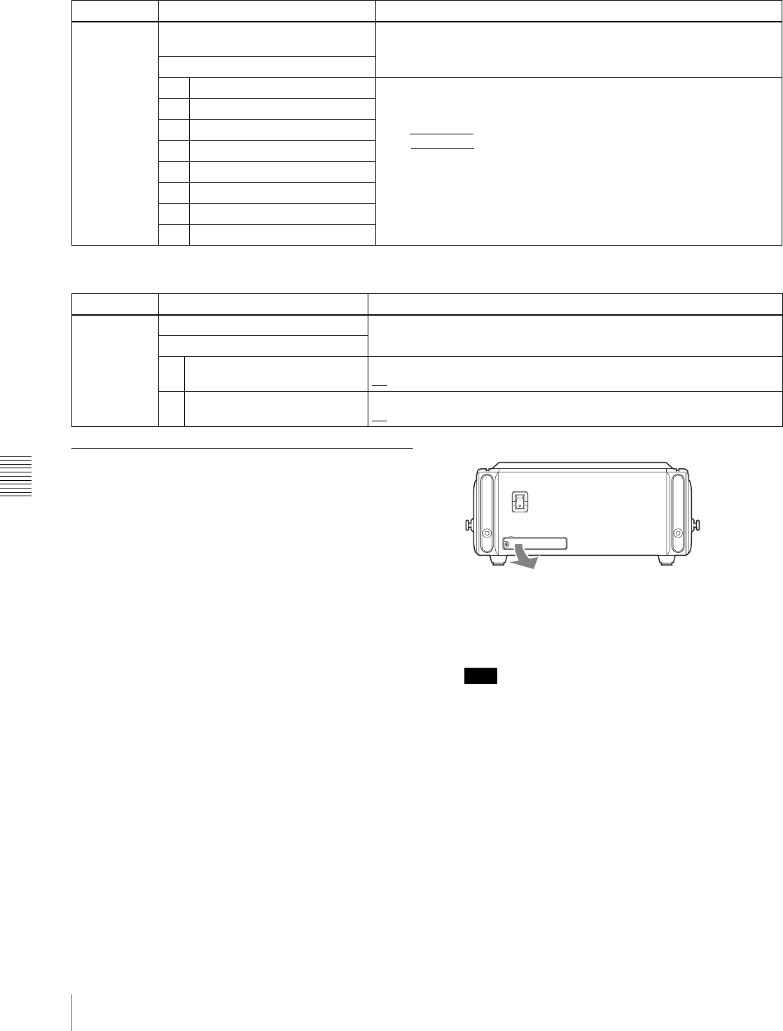
Chapter 7 Menus
108 7-3 Extended Menu
7-3-2 Extended Menu Operations
The extended menu can be used with the same procedures
as in the basic menu.
However, since with the factory default settings the
extended menu is not displayed, it is first necessary to
enable display of the extended menu.
See “Basic setup menu operations” (page 94) for more
information about how to select menu items and how to
change their values.
Enabling display of the extended menu
To enable display of the extended menu, an internal switch
must be set to on, and extended menu display must be
enabled in the maintenance menu. (The internal switch is
set to on when the unit is shipped from the factory. Unless
you have set it to off, there is no need to change the switch
setting.)
To set the internal switch to on
1
Using a Phillips screwdriver, remove the cover on the
rear panel of this unit
2
Use a ballpoint pen or other sharp implement to set the
leftmost of the DIP switches on the right side to the
ON (top) position.
Note
Do not use a pencil for this operation, as graphite
deposits can cause short circuits and lead to failure.
838 AUDIO MONITOR CHANNEL
ARRANGE Together with item 837, select the audio signals (tracks 5 to 8) to assign
to the left and right channels of the audio monitor.
Sub-item
L-5 Lch/tr5 No display: Do not assign.
on: Assign.
The factory default settings are as follows.
Lch: No display
Rch: No display
L-6 Lch/tr6
L-7 Lch/tr7
L-8 Lch/tr8
R-5 Rch/tr5
R-6 Rch/tr6
R-7 Rch/tr7
R-8 Rch/tr8
Menu items in the 800s, relating to audio control
Item number Item name Settings
Menu items in the 900s, relating to digital process
Item number Item name Settings
920 SD-SDI H-ANC CONTROL Select whether or not to add information to the SDI output.
Sub-item
1 AUDIO 5CH-8CH off: Do not add digital audio data channels 5 to 8.
on: Add digital audio data channels 5 to 8.
2 RP188 ATC off: Do not add RP188 time code data.
on: Add RP188 time code data.
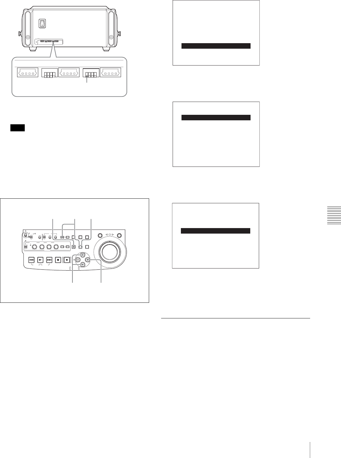
Chapter 7 Menus
109
7-3 Extended Menu
3
Replace the cover.
Note
Tighten the screws firmly.
To enable extended menu display in the
maintenance menu
The menu screens in the following procedure are those that
appear in the video panel, and on a monitor to which the
output of the VIDEO OUT 2 (SUPER)/SDI OUT
(SUPER) connector is input.
Proceed as follows.
1
Press the MENU button.
The setup menu appears in the video panel and on the
external monitor.
2
Hold down the COUNTER SEL button, and press the
SET button.
The screen switches to the maintenance menu.
3
Use the F/f buttons to select “SETUP
MAINTENANCE.”
4
Press the g button.
5
Use the F/f buttons to select “EXTENDED MENU.”
6
Press the g button.
7
Press the f button to select “ENABLE.”
8
Press the SET button.
When you next display the menu and change the item
display, the extended menu will appear after the basic
menu.
7-3-3 Using UMID Data
To perform operations from interviewing to editing
effectively and to detect audio-visual materials easily
when reusing them, metadata that provides additional
information is recorded along with audio-visual data. As
one of application of metadata, the UMID (Unique
Material Identifier) is internationally standardized.
12341234
12341234
Set this switch to “ON.”
ACCESS
SHUTTLE JOG
THUMB
NAIL
ESSENCE
MARK
MENU
S.SEL
SET RESET
SHIFT
TOP F REV
ALL/CH-1 CH-2 CH-3 CH-4
TC
F FWD
AUDI O
END
REC
PRESET
VARIABLE
PB
PREV NEXTPLAY STOP REC
CLIP
MENU
SYSTEM
MENU
MONITOR
SEL
METER
SEL
HOLD
COUNTER
SEL
SUB
CLIP
MARK1
MARK2
IN OUT
KEY INHI
ON
OFF
NETWORK
LOCAL
REMOTE
F-RUN
R-RUN
PRESET
REGEN
INT
EXT
RP188
L/ST/R
4,63,5,7
128
ADJUST
DRIVE MAINTENANCE
MAINTENANCE MENU
BATTERY CONFIG
AUDIO CONFIG
CHECK
NETWORK CONFIG
SETUP MAINTENANCE t
SERVICE SUPPORT
OTHERS
EXTENDED MENU : dis
SETUP MAINTENANCE
MAINTENANCE MENU
SAVE MENU DATA
LOAD MENU DATA
SETUP BANK4
AU BANK RECALL: off
RESET ALL SETUP
T t
EXTENDED MENU : dis
SETUP MAINTENANCE
MAINTENANCE MENU
ENABLE
* DISABLE
T
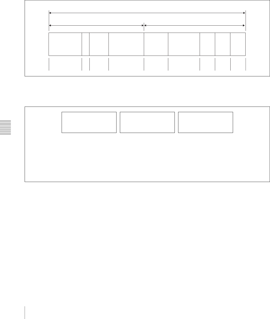
Chapter 7 Menus
110 7-3 Extended Menu
What is a UMID?
The UMID (Unique Material Identifier) is a unique
identifier for audio-visual material defined by the
SMPTE330M-2003 standard.
The UMID may be used either as the 32-byte Basic UMID
or as the Extended UMID, which includes an additional 32
bytes of Source Pack to make a total 64 bytes.
For details, refer to SMPTE 330M.
Globally unique ID is automatically recorded in clip units.
The Extended UMID is metadata that provides additional
information such as location, time/date, company and so
on.
The UMID is applied as follows.
Using the Extended UMID
You have to enter a country code, organization code and
user code. Set the country code referring to the ISO-3166
table, and set the organization code and user code
independently.
For details, see “About UMID ownership information”
(page 111).
Functions of UMID data
The UMID data enables the followings:
• Add a globally unique ID to every clip of audio-visual
material. The unique ID is used to detect the material
source and to link it with the original source material.
• Distinguishing between original material and copied
material. 00 is added to the Instance Number for original
material.
• Recording based on the UTC. The UTC is used when
recording the UMID. This enables uniform control of
source material recorded all over the world based on the
universal time code.
• Calculating the date difference among source materials.
The source material is recorded based on the MJD
(Modified Julian Date), which enables easy calculation
of date difference among source materials.
Setting UMID ownership information
Proceed as follows.
1
Set extended menu item 029 “STORED
OWNERSHIP” to “on.”
See 7-2-2 “Basic Menu Operations” (page 94) for
more information about how to make this setting.
Extended UMID (64 bytes)
Basic UMID (32 bytes) Source Pack (32 bytes)
Universal label L Inst. No. Material Number Time/Date Spatial
Co-ordinates Country Org User
12 bytes 1 3 bytes 16 bytes 8 bytes 12 bytes 4 bytes 4 bytes 4 bytes
Instance No.
Material No.
ID generated when
recording
Same as the above
Source Pack
Shooting information (when,
where and who)
Same as the above
M
Distinguishing between the
original material and copied
material
M
Material source ID/detecting
material
M
Metadata pack that identifies
the source of material unit by
defining the when, where
and who of the material unit
with which it is associated.
Original material: 00 00 00
Copied material: generation number
(1 byte) + random number (2 bytes)

Chapter 7 Menus
111
7-3 Extended Menu
2
Set the following item.
To change the currently selected item
Hold down the STOP button, and turn the jog dial or
shuttle dial.
To select a different digit to be changed
Turn the jog dial or shuttle dial.
To change the value of a digit
Hold down the SHUTTLE button, and turn the jog dial
or shuttle dial.
3
Press the SET button.
About UMID ownership information
COUNTRY (country code)
Enter an abbreviated alphanumeric string (4-byte
alphanumeric strings) according to the values defined in
ISO 3166-1.
There are about 240 country codes.
Find your own country code on the following home page.
Refer to ISO-3166-1:
http://www.evertype.com/standards/iso3166/iso3166-1-
en.html
When the country code is less than 4 bytes, the active part
of the code will occupy the first part of the 4-bytes and the
remainder must be filled with the space character (20h).
Example: In the case of Japan
For Japan, if the country code is JP, it is 2 bytes, if JPN, it
is 3 bytes.
Thus, enter the following:
JP_ _
or
JPN _
where _ represents a space.
ORGANIZATION (organization code)
Enter an abbreviated 4-byte alphanumeric string for the
organization code.
Notes
• Organization codes must be acquired by applying to the
SMPTE registration office.
When no organization code has been acquired, it is
forbidden to enter an arbitrary string. As a rule, the code
“00” must be entered. Freelance operators who do not
belong to an origination should enter “~.”
• There are no problems in recording or playing back
audio-video signals, if ORGANIZATION is not set.
USER (user code)
Enter the 4-byte alphanumeric strings for user
identification.
The user code is registered with each organization locally.
It is usually not centrally registered.
When the country code is less than 4 bytes, enter the
country code from the beginning of the 4 bytes and enter
the space character (20h) in the remaining strings.
This user code is determined by the organization. The
methods used depend on the organization.
Note
User code cannot be entered when no organization code
has been entered.
Item Contents
COUNTRY Country code
ORGANIZATION Organization code
USER User code
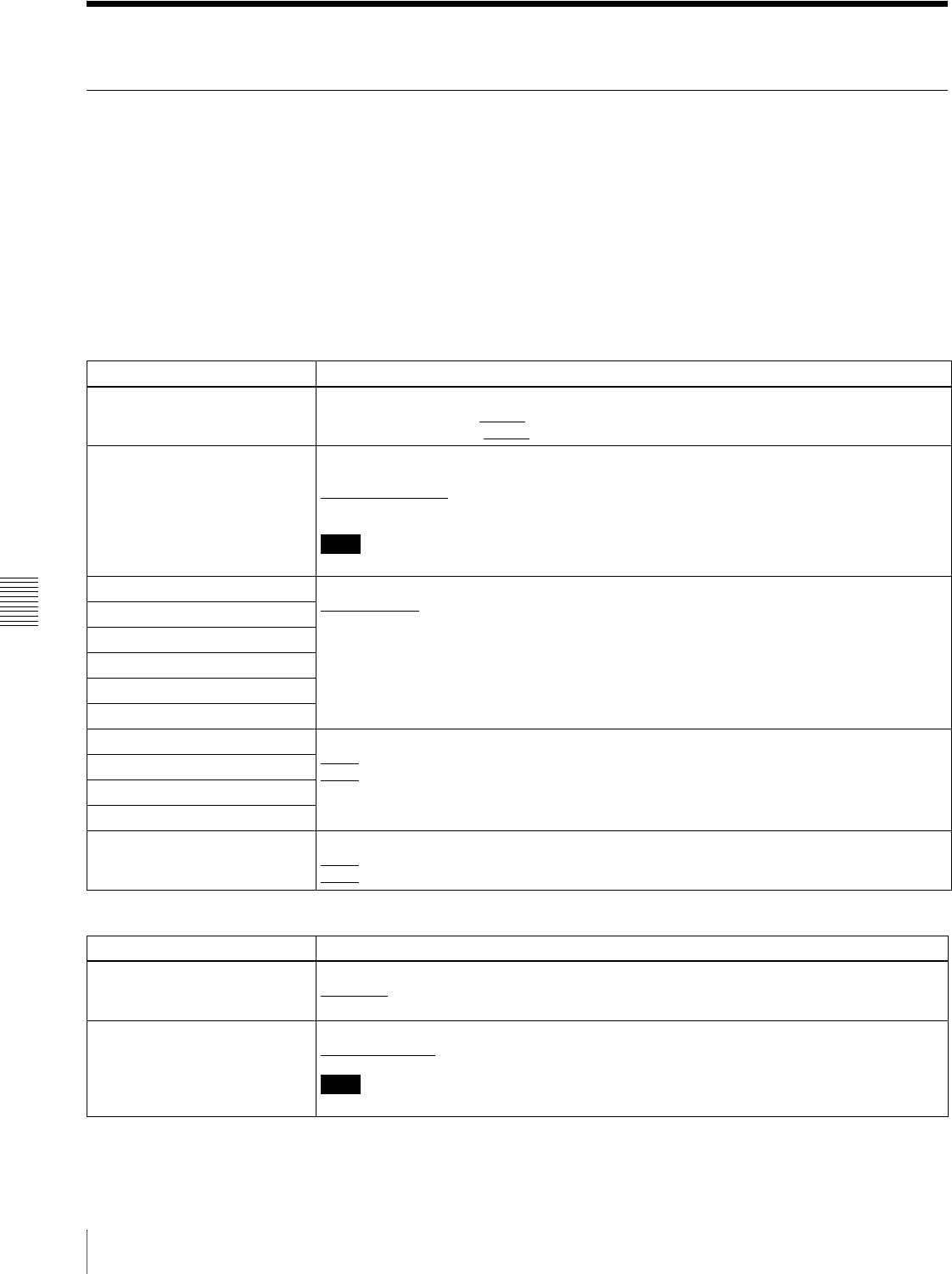
Chapter 7 Menus
112 7-4 Maintenance Menu
7-4 Maintenance Menu
7-4-1 Items in the Maintenance Menu
The following tables show the items in the maintenance
menu.
• Item names are the names which appear in the video
panel, and on an external monitor to which the output of
the VIDEO OUT 2 (SUPER)/SDI OUT (SUPER)
connector is input.
• The values in the Settings columns are the values which
appear in the time data display section. (The values may
appear in a different format in the video panel and on an
external monitor. In this case, the video panel values are
shown in parentheses.) Underlined values are the factory
defaults.
For information about the DRIVE MAINTENANCE,
ADJUST, CHECK, BATTERY CONFIG and SERVICE
SUPPORT items, refer to the Maintenance Manual.
AUDIO CONFIG: items relating to audio control
Item Setting
METR HEAD ROOM Select the audio reference level (headroom).
–12dB,–16dB, –18dB, –20dB (525(U)/525(J) line modes)
–12dB, –16dB, –18dB, –20dB, EBUL (625 line mode)
DATA LENGTH When “IMX50,” “IMX40,” or “IMX30” is selected in setup menu item 031, this selects the
audio quantization bit count and number of recording channels.
16×8 (16bit × 8ch): 16 bits × 8 channels
24×4 (24bit × 4ch): 24 bits × 4 channels
Note
When item 031 is set to “DVCAM,” the setting is automatically fixed at 16 bits × 4 channels.
NON-AUDIO INPUT Select whether to handle digital audio signals as non-audio signals during recording.
Audio (audio): Handle as audio signals.
data: Handle as non-audio signals.
Sub-item
tr1/tr2
tr3/tr4
tr5/tr6
tr7/tr8
INPUT LEVEL Set the upper limit for the signal level input to audio channels 1/3 or 2/4.
+4dB, 0dB, –3dB, –6dB (525(U)/525(J) line modes)
+4dB, 0dB, –3dB, –6dB, EBUL (625 line mode)
Sub-item
CH1/CH3
CH2/CH4
OUTPUT LEVEL Set the reference level for audio output signals.
+4dB, 0dB, –3dB, –6dB (525(U)/525(J) line modes)
+4dB, 0dB, –3dB, –6dB, EBUL (625 line mode)
NETWORK CONFIG: items relating to network settings
Item Setting
DHCP Set whether to assign an IP address automatically with the DHCP server.
DISABLE: Do not assign automatically.
ENABLE: Assign automatically.
IP ADDRESS PRESET Set IP address.
192.168.001.010
Note
When DHCP is set to “ENABLE,” it is not possible to set the IP address.
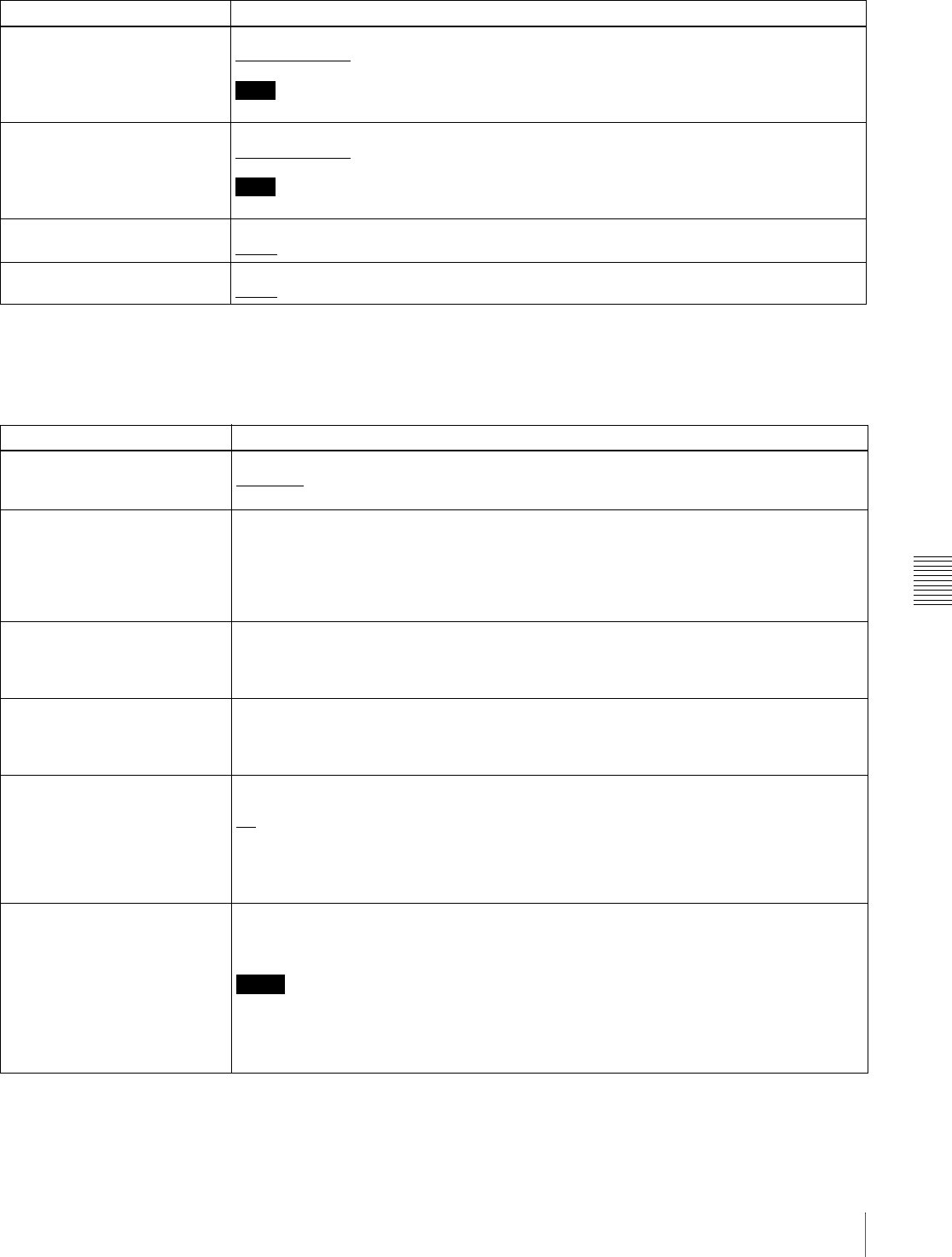
Chapter 7 Menus
113
7-4 Maintenance Menu
For details of how to make settings, see “To change
network settings” (page 115).
SUBNET MASK PRESET Set the subnet mask.
255.255.255.000
Note
When DHCP is set to “ENABLE,” it is not possible to set the subnet mask.
DEFAULT GATEWAY PRESET Set the default gateway.
000.000.000.000
Note
When DHCP is set to “ENABLE,” it is not possible to set the default gateway.
LINK SPEED Set the communications speed.
AUTO, 10Mbps, 100Mbps
DUPLEX Set the communications method.
AUTO, Full (Full Duplex), Half (Half Duplex)
NETWORK CONFIG: items relating to network settings
Item Setting
SETUP MAINTENANCE: items relating to the setup menu
Item Setting
EXTENDED MENU Select whether or not to display the extended menu.
DISABLE: Do not display.
ENABLE: Display.
SETUP BANK4 Select the bank to be stored in menu bank 4, or reset menu bank 4.
Cur to 4 (CURRENT TO BANK4): Store the current menu settings in menu bank 4.
1 to 4 (BANK1 TO BANK4): Store the menu bank 1 settings in menu bank 4.
2 to 4 (BANK2 TO BANK4): Store the menu bank 2 settings in menu bank 4.
3 to 4 (BANK3 TO BANK4): Store the menu bank 3 settings in menu bank 4.
Reset (RESET BANK4): Reset menu bank 4.
SAVE MENU DATA Select whether to temporarily back up (save) setup menu settings before operations such as
software upgrades.
SET button: Back up (save) the settings.
MENU button: Return to next highest menu level without backing up.
LOAD MENU DATA Select whether to restore (load) setting that were backed up (saved) with the “SAVE MENU
DATA” item.
SET button: Restore (load) the settings.
MENU button: Return to the next highest menu level without restoring.
AU BANK RECALL Select whether to recall settings automatically from a menu bank when the system is
powered on, and if so which menu bank to recall from.
off: Do not recall settings from a menu bank.
Bank1 (from BANK1): Recall settings from menu bank 1.
Bank2 (from BANK2): Recall settings from menu bank 2.
Bank3 (from BANK3): Recall settings from menu bank 3.
Bank4 (from BANK4): Recall settings from menu bank 4.
RESET ALL SETUP Reset the current menu settings to the factory settings.
SET button: Reset.
MENU button: Return to the next highest menu level without resetting.
Notes
• The line mode setting is also cleared. If you execute this item, reset the line mode (see
page 7).
• Date and time settings are not cleared, but the time zone setting is cleared. After executing
this item, reset the time zone (see page 34).
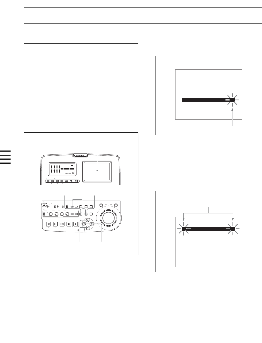
Chapter 7 Menus
114 7-4 Maintenance Menu
For details about OTHERS items other than the above,
refer to the Maintenance Manual.
7-4-2 Maintenance Menu Operations
Basic maintenance menu operations
The following explains how to select maintenance menu
items and how to change their values. The menu screen
shown are those that appear in the video panel and on a
monitor to which the output of the VIDEO OUT 2
(SUPER)/SDI OUT (SUPER) connector is input.
First change the switch setting within the unit, then carry
out the following operations.
For information about how to change the switch setting
within the unit, see page 108.
1
Press the MENU button.
The menu appears in the video panel and on the
external monitor.
2
Hold down the COUNTER SEL button, and press the
SET button.
The group selection screen of the maintenance menu
appears. The currently selected item group is
highlighted, and the arrow (c) flashes to indicate that
you can move to a lower-level menu.
To select the item group
Use the F/f buttons.
3
Press the g button.
A lower-level menu (item selection screen) appears.
The currently selected item is highlighted, and the
arrow (C/c) flashes to indication that you can move to
a higher- or lower-level menu.
To return to the item group
Press the G button.
To select the menu item
Use the F/f buttons.
OTHERS
Item Setting
SDI SUPER Select whether to output superimpose characters to the SDI OUT (SUPER) connector.
ON: Output.
OFF: Do not output.
AUDIO VIDEO
INPUT SEL
WARNING KEY INHI REC INHI
INPUT CH INPUT SEL STATUS LIGHT MONITOR
HLOFFOFF ON
OFF ON
-30
dB
-12
-20
-40
-60
0
CH
- 15
DATA
OVER
-30
dB
-12
-20
-40
-60
0
CH-
26
DATA
OVER
-30
dB
-12
-20
-40
-60
0
CH-
37
DATA
OVER
-30
dB
-12
-20
-40
-60
0
CH-
48 BATT E F
DATA
OVER
VITC
HOURS MINUTES SECONDS FRAMES
COUNTER HOLDVIUB
PB EXT-LKNDF
DISC E B
ACCESS
SHUTTLE JOG
THUMB
NAIL
ESSENCE
MARK
MENU
S.SEL
SET RESET
SHIFT
TOP F REV
ALL/CH-1 CH-2 CH-3 CH-4
TC
F FWD
AUDI O
END
REC
PRESET
VARIABLE
PB
PREV NEXTPLAY STOP REC
CLIP
MENU
SYSTEM
MENU
MONITOR
SEL
METER
SEL
HOLD
COUNTER
SEL
SUB
CLIP
MARK1
MARK2
IN OUT
KEY INHI
ON
OFF
NETWORK
LOCAL
REMOTE
F-RUN
R-RUN
PRESET
REGEN
INT
EXT
RP188
L/ST/R
CHARACTER
VITC
PROCESS
CONTROL
3,42,3,5
126
Video panel
ADJUST
DRIVE MAINTENANCE
MAINTENANCE MENU
BATTERY CONFIG
AUDIO CONFIG
CHECK
NETWORK CONFIG t
SETUP MAINTENANCE
SERVICE SUPPORT
OTHERS
Flashing
Group selection screen
IP ADDRESS
DHCP : dis
NETWORK CONFIG
MAINTENANCE MENU
SUBNET MASK
DEFAULT GATEWAY
LINK SPEED : auto
DUPLEX : auto
T t
Flashing
Item selection screen
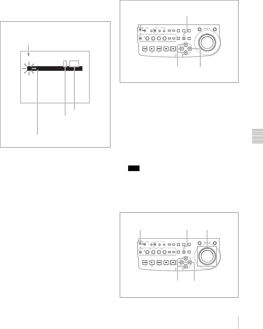
Chapter 7 Menus
115
7-4 Maintenance Menu
4
Press the g button.
A lower-level menu (setting modification screen)
appears. The current setting is highlighted, and the
arrow (C) flashes to indicate that you can move to a
higher-level menu. If the current setting is the factory
default, a colon (:) appears between the item name and
the setting. A midpoint (•) appears if you change the
factory default setting to another value and then
display the setting modification screen again.
To return to the menu item
Press the G button.
When there is a sub-item
Repeat steps 3 and 4 until the setting modification
screen appears.
5
Using the F/f buttons to select the desired setting.
6
Press the SET button.
This saves the new setting, and the menu disappears
from the video panel or an external monitor.
To cancel changing a setting
Before pressing the SET button, press the MENU
button.
The menu disappears from the video panel or an
external monitor, without saving the new setting.
To change network settings
To change network settings, carry out steps 1 to 3 in the
procedure of “Basic maintenance menu operations” above,
to display the NETWORK CONFIG menu item, then carry
out the following operations.
For details of the settings, consult your network
administrator.
When the IP address is assigned automatically
Check that the network cable is connected to this unit
before carrying out the operation.
1
Using the F/f buttons to select “DHCP.”
2
Press the g button.
3
Press the f button to select “ENABLE.”
4
Press the SET button.
To check the assigned IP address
In the NETWORK CONFIG menu, using the F/f
buttons to select “IP ADDRESS,” then press the g
button.
Note
If the IP address cannot be assigned, this is shown as
“000.000.000.000.” In this case, consult the network
administrator.
To set the IP address
First set DHCP to “DISABLE.” (See the previous item,
“When the IP address is assigned automatically.”)
* DISABLE
DHCP : dis
NETWORK CONFIG
MAINTENANCE MENU
ENABLE
T
Flashes
Setting modification screen
Indicates a factory default setting
Indicates that the current setting is
the factory default (change to “•” if
the default setting is changed)
Current setting
ACCESS
SHUTTLE JOG
THUMB
NAIL
ESSENCE
MARK
MENU
S.SEL
SET RESET
SHIFT
TOP F REV
ALL/CH-1 CH-2 CH-3 CH-4
TC
F FWD
AUDI O
END
REC
PRESET
VARIABLE
PB
PREV NEXTPLAY STOP REC
CLIP
MENU
SYSTEM
MENU
MONITOR
SEL
METER
SEL
HOLD
COUNTER
SEL
SUB
CLIP
MARK1
MARK2
IN OUT
KEY INHI
ON
OFF
NETWORK
LOCAL
REMOTE
F-RUN
R-RUN
PRESET
REGEN
INT
EXT
RP188
L/ST/R
21,3
4
ACCESS
SHUTTLE JOG
THUMB
NAIL
ESSENCE
MARK
MENU
S.SEL
SET RESET
SHIFT
TOP F REV
ALL/CH-1 CH-2 CH-3 CH-4
TC
F FWD
AUDI O
END
REC
PRESET
VARIABLE
PB
PREV NEXTPLAY STOP REC
CLIP
MENU
SYSTEM
MENU
MONITOR
SEL
METER
SEL
HOLD
COUNTER
SEL
SUB
CLIP
MARK1
MARK2
IN OUT
KEY INHI
ON
OFF
NETWORK
LOCAL
REMOTE
F-RUN
R-RUN
PRESET
REGEN
INT
EXT
RP188
L/ST/R
2,31,3
4,673

Chapter 7 Menus
116 7-4 Maintenance Menu
1
Using the F/f buttons to select “IP ADDRESS.”
2
Press the g button.
The IP ADDRESS PRESET menu appears, and the
digit that can be changed flashes.
3
Set the IP address.
To select a different digit to be changed
Use the G/g buttons.
To change the value of a digit
Turn the jog dial or shuttle dial.
Turning clockwise increases the value, and turning
counterclockwise decreases the value.
The F/f buttons can be used.
To return to the factory default setting
Press the RESET button.
4
When all digits are set, press the SET button.
This returns to the NETWORK CONFIG menu.
To cancel a setting
Before pressing the SET button, press the MENU
button.
This returns to the NETWORK CONFIG menu,
without saving the new setting.
5
Repeat steps 1 to 4 as required, to set the subnet mask
and default gateway.
6
In the NETWORK CONFIG menu, press the SET
button.
7
When the “NOW SAVING...” message vanishes,
power the unit off and then on again with the on/
standby switch.
Setting the communications speed
Set the communications speed (LINK SPEED) and
communications method (DUPLEX) to match the network
environment.
For details of the operation, see “Basic maintenance menu
operations” (page 114).
IP ADDRESS PRESET
DHCP: disable
IP : 192.168.001.010
SHIFT : (
C
)(
c
)KEY
INC/DEC : JOG DIAL
DATA SET : SET KEY
TO MENU : MENU KEY
CLEAR : RESET KEY
Flashing
Item selection screen
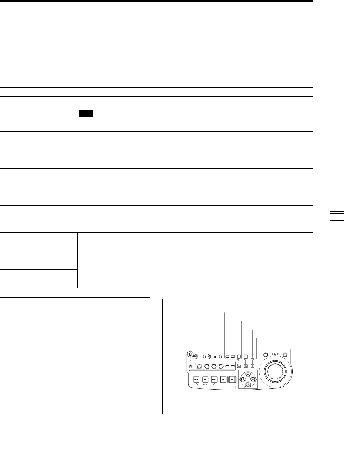
Chapter 7 Menus
117
7-5 System Menu
7-5 System Menu
7-5-1 Items in the System Menu
The following tables show the items in the system menu.
Item names are the names which appear in the video panel,
and on an external monitor to which the output of the
VIDEO OUT 2 (SUPER)/SDI OUT (SUPER) connector is
input.
7-5-2 System Menu Operations
DISC MENU: items relating to disc
Item Setting
STATUS Display disc status or clip status.
Note
Although the PDZ-1 Proxy Browsing Software can write TITLE1 and TITLE2, only TITLE1 is
displayed here.
Sub-item
1 DISC Display disc status.
2 CLIP Display clip status.
DELETE Delete clips on the disc.
Sub-item
1 LAST CLIP Delete the last clip.
2 ALL CLIP Delete all the clips. (Locked files and files in the General directory cannot be deleted.)
FORMAT Select the disc format, and carry out formatting.
Sub-item
1 QUICK FORMAT Quick format (Deletes all data on the disc, including the contents of the General directory.)
DATE/TIME PRESET: items relating to date and time setting
Item Setting
YEAR Set the year, month, day, time, and time zone.
MONTH
DAY
TIME
TIME ZONE
ACCESS
SHUTTLE JOG
THUMB
NAIL
ESSENCE
MARK
MENU
S.SEL
SET RESET
SHIFT
TOP F REV
ALL/CH-1 CH-2 CH-3 CH-4
TC
F FWD
AUDI O
END
REC
PRESET
VARIABLE
PB
PREV NEXTPLAY STOP REC
CLIP
MENU
SYSTEM
MENU
MONITOR
SEL
METER
SEL
HOLD
COUNTER
SEL
SUB
CLIP
MARK1
MARK2
IN OUT
KEY INHI
ON
OFF
NETWORK
LOCAL
REMOTE
F-RUN
R-RUN
PRESET
REGEN
INT
EXT
RP188
L/ST/R
MENU button
SHIFT button
RESET button
Arrow buttons
SET button

Chapter 7 Menus
118 7-5 System Menu
To display disc status and clip status
Insert a disc and proceed as follows.
1
Hold down the SHIFT button and press the MENU
button.
The system menu appears in the video panel or on an
external monitor.
2
Press the F button or f button to select “DISC
MENU,” then press the g button.
The DISC MENU page appears.
3
Press the F button or f button to select “STATUS,”
then press the g button.
The “STATUS” menu item appears.
4
Display the disc status or the status of the current clip.
To display the disc status
Press the F button or f button to select “DISC,” then
press the g button.
The status of the loaded disc appears.
To display the status of the current clip
Press the F button or f button to select “CLIP,” then
press the g button.
The status of the clip at the current position appears.
(When the current clip changes because of playback or
a search, the display switches to the status of the new
clip.)
To return to the previous menu page
Press the MENU button.
To exit the menu system
Press the MENU button twice.
To delete clips
Notes
• Clips cannot be deleted when the Write Inhibit tab of the
disc is set to the recording disabled position, or when
extended menu item 310 “REC INHIBIT” is set to “on.”
• Locked clips (see page 55) are not deleted.
Proceed as follows.
1
Carry out steps 1 and 2 in the previous section “To
display disc status and clip status.”
2
Press the F button or f button to select “DELETE,”
then press the g button.
The “DELETE” menu item appears.
3
Delete the last clip or all clips.
To delete the last clip
Press the F button or f button to select “LAST CLIP,”
then press the g button.
The name of the clip to be deleted appears.
To cancel the deletion and return to the previous page,
press the MENU button.
To delete all clips
Press the F button or f button to select “ALL CLIP,”
then press the g button.
The message “ALL DELETE OK?” appears.
To cancel the deletion and return to the previous page,
press the RESET button.
To cancel the deletion and exit the menu system, press
the MENU button.
4
Press the SET button.
The last clip is deleted, or all clips are deleted.
You can use the THUMBNAIL MENU to delete the
selected clip or all clips. For details, see page 56.
To format discs
See 3-6-5 “Formatting a Disc” (page 39).
USER ID: (no ID)
TITLE : (no name)
REMAIN : 029 min
REWRITE : 0002 times
SALVAGE : OK
FILE SYSTEM : OK
TO MENU : MENU KEY
DISC STATUS
NAME : C0001
TITLE: (no name)
RECORD DEVICE: PDW-R1
SERIAL: 10001
DATE : 01/01/06
TIME : 19:54:38
TO MENU : MENU KEY
CLIP STATUS
CLIP NO : 001/010

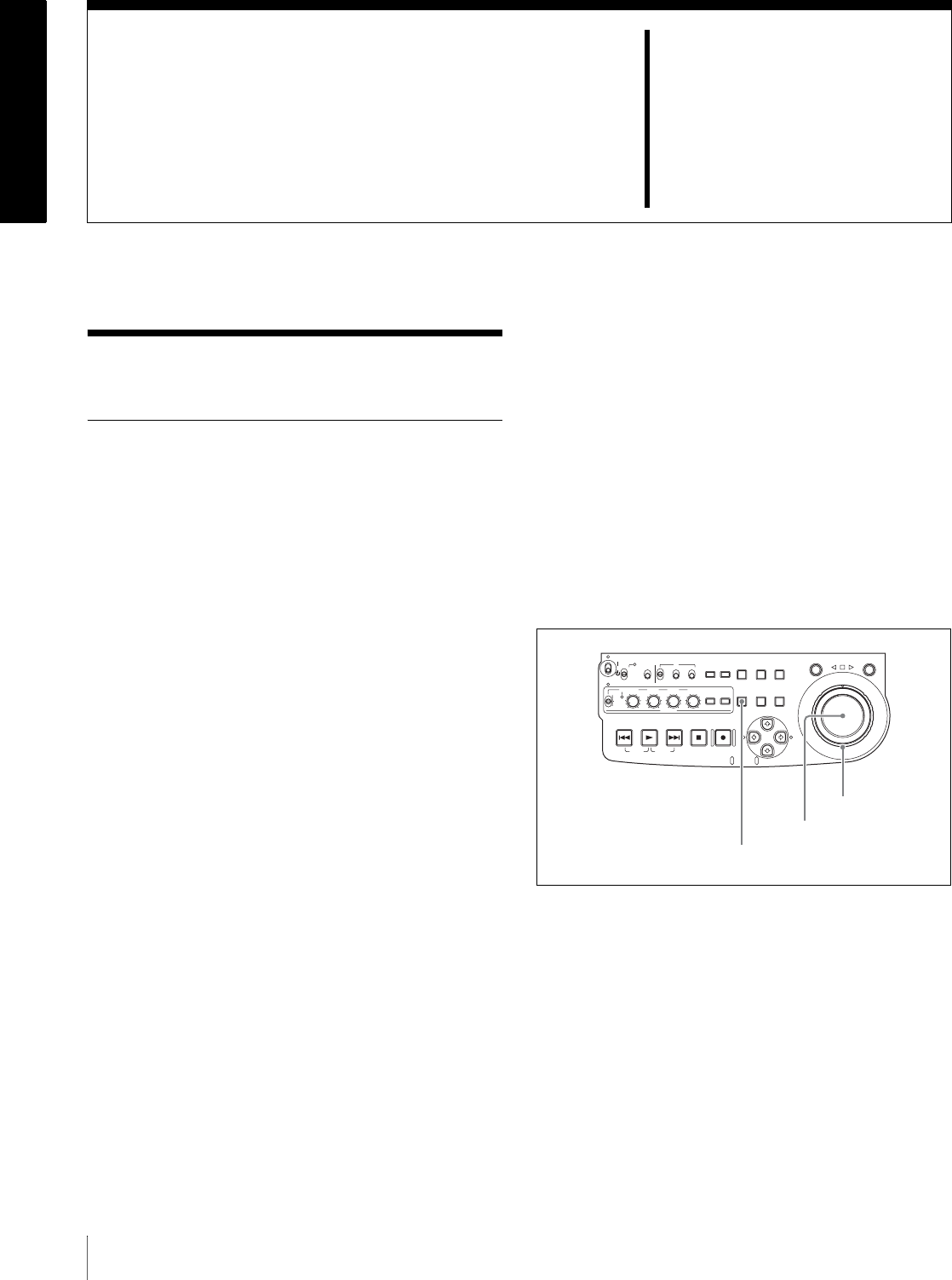
120 8-1 Periodic Maintenance
Chapter8
Maintenance and
Troubleshooting
8-1Periodic Maintenance
8-1-1 Digital Hours Meter
The digital hours meter can provide six items of
information about the operational history of the unit. This
information appears in the time data display section, in the
video panel, and on an external monitor to which the
output of the VIDEO OUT 2 (SUPER)/SDI OUT
(SUPER) connector is input. Use the information as a
guide in scheduling periodic maintenance.
For periodic maintenance, consult your Sony dealer.
Display modes of the digital hours meter
H01: OPERATION mode
Displays the total number of hours the unit has been
powered on in units of 1 hour.
H11: OPERATION mode (resettable)
Same as H01 except that the count is resettable.
This can be used as a guide in determining when to replace
parts.
H12: LASER PARAMETER mode (resettable)
This shows a counter of the cumulative light output time
by the optical head in units of hours. 1) The count is
resettable.
This can be used as a guide in determining when to replace
the optical head.
1) The counter advances at different rates during recording and playback. It
is also affected by the ambient temperature.
H13: SEEK RUNNING mode (resettable)
This shows the cumulative seek operation time for the
optical head in units of hours. The count is resettable.
This can be used as a guide in determining when to replace
the seek motor.
H14: SPINDLE RUNNING mode (resettable)
This shows the cumulative spindle rotation time, in units of
hours. The count is resettable.
This can be used as a guide in determining when to replace
the spindle motor.
H15: LOADING COUNTER mode (resettable)
Display the total number of times disc has been loaded in
the unit. The count is resettable.
To display the digital hours meter
Press the MENU button, then turn the jog dial or shuttle
dial to display the required item in the time data display
and in the video panel or on an external monitor.
To exit from the digital hours meter
Press the MENU button.
To jump to H01
Press the MENU button, then the COUNTER SEL button.
Every time you press the COUNTER SEL button, menu
item H01 or B01 is recalled alternately.
ACCESS
SHUTTLE JOG
THUMB
NAIL
ESSENCE
MARK
MENU
S.SEL
SET RESET
SHIFT
TOP F REV
ALL/CH-1 CH-2 CH-3 CH-4
TC
F FWD
AUDI O
END
REC
PRESET
VARIABLE
PB
PREV NEXTPLAY STOP REC
CLIP
MENU
SYSTEM
MENU
MONITOR
SEL
METER
SEL
HOLD
COUNTER
SEL
SUB
CLIP
MARK1
MARK2
IN OUT
KEY INHI
ON
OFF
NETWORK
LOCAL
REMOTE
F-RUN
R-RUN
PRESET
REGEN
INT
EXT
RP188
L/ST/R
MENU button
Shuttle dial
Jog dial
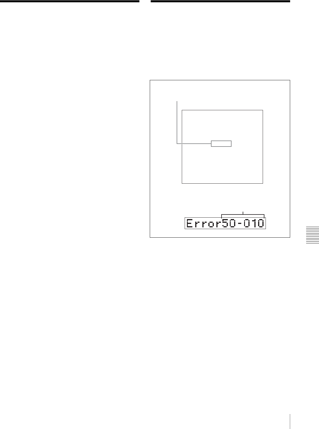
121
8-2 Condensation / 8-3 Error Messages
Chapter 8 Maintenance and Troubleshooting
8-2Condensation
When this unit is moved from a cold place to a warmer
place, or operated in high humidity, condensation may
form on the optical pickup. This is called condensation,
and if the unit is operated in this state, it may make correct
recording and playback impossible.
Note the following points, to avoid problems with
condensation.
• When moving the unit under conditions in which
condensation is likely, first insert the disc, and close the
lid on the disc slot.
• If when you move the on/standby switch to the ` position
the indication “HUMID” appears in the status display,
do not insert a disc until the indication disappears.
8-3Error Messages
Error codes appear in the time data display when an error
(usually a hardware problem) occurs. Error codes and error
messages appear in the video panel, and on an external
monitor to which the output of the VIDEO OUT 2
(SUPER)/SDI OUT (SUPER) connector is input.
When an error message appears, follow the instructions in
the error message to resolve the problem.
AN ERROR HAS BEEN
DETECTED. INFORM SERVICE
OF FOLLOWING CODE:
50-010
PRESS EJECT KEY
TO EJECT DISC.
ERROR
Error code
Display in time data display
Error code
Display in video panel and on external monitor

Chapter 8 Maintenance and Troubleshooting
122 8-4 Alarms
8-4Alarms
An alarm (warning message) appears in the time data
display when an operation is attempted which is
inappropriate for the settings on this unit or the state of the
disc. The video panel and an external monitor to which the
output of the VIDEO OUT 2 (SUPER)/SDI OUT
(SUPER) connector is input displays the alarm message
and also the action to take to resolve the problem.
8-4-1 Alarm List
The following tables list the alarms displayed by this unit,
categorized according to the state of the unit when the
alarms occur.
The setting of basic menu item 016 “ALARM DISPLAY”
determines whether or not some of these alarms appear.
The “Display condition” column in the tables shows
whether the alarm is displayed according to or regardless
of the setting of menu item 016.
See 7-2-2 “Basic Menu Operations” (page 94) for more
information about how to set menu item 016.
REMOTE MODE IS SELECTED.
SET REMOTE/LOCAL/NETWORK
SWITCH TO LOCAL.
ALARM
Display in video panel and on external monitor
Display in time data display

Chapter 8 Maintenance and Troubleshooting
123
8-4 Alarms
When the unit is powered on
a) With respect to setting of basic menu item 016
When a disc is inserted
Message in time
data display
Display
condition a)
Description Action
MENU Ver.UP on, limit, off Setup menu settings were reset,
because this unit was upgraded. Reset the setup menu items.
See 7-2-2 “Basic Menu Operations” (page
94) and 7-3-2 “Extended Menu Operations”
(page 108) for information about making
setup menu settings.
Maintenance menu item “SETUP
MAINTENANCE” - “SAVE MENU DATA/
LOAD MENU DATA” (see page 113) can be
used to temporarily back up and restore the
current menu settings.
ILL. SETUP! on, limit, off Setup menu data is invalid, or data
recalled with the maintenance menu
item “SETUP MAINTENANCE” –
“AUTO BANK RECALL” is invalid.
Reset the items in the setup menu.
Exchg batt! on, limit, off NVRAM battery is exhausted. It is time to exchange the battery on the
board. Contact your Sony service
representative.
LOW BATT! on, limit, off Battery pack power is low. Exchange with a charged battery pack.
See 3-2-3 “Using a Battery Pack” (page 33)
for more information about exchanging
battery packs.
BATT EMPTY! on, limit, off Battery pack power is exhausted.
Message in time
data display
Display
condition a)
Description Action
Unknown FS! on, limit, off The loaded disc was formatted by an
unknown file system. Eject or format the disc.
See 3-6-5 “Formatting a Disc” (page 39) for
more information about formatting.
No FS! on, limit, off The file system cannot be detected. Eject the disc.
ILL. Disc! on, limit, off An unsupported disc was inserted.
Salvage NG on, limit, off Recovery of disc contents (salvage)
failed. See 3-6-7 “Handling of Discs When
Recording Does Not End Normally
(Salvage Function)” (page 40).
525/60 Clip on, limit A disc recorded in NTSC format was
inserted when this unit is in 625 line
mode (PAL system).
Use a disc recorded with the PAL system.
625/50 Clip on, limit A disc recorded in PAL format was
inserted when this unit is in 525(U) or
525(J) line mode (NTSC system).
Use a disc recorded with the NTSC
system.
IMX50 Clip
IMX40 Clip
IMX30 Clip
DVCAM Clip
on, limit The recording format of the loaded disc
differs from the format specified with
basic menu item 031 “RECORDING
FORMAT.”
To record on the disc, change the setting of
basic menu item 031.
See 7-2-2 “Basic Menu Operations” (page
94) about how to change this setting.

Chapter 8 Maintenance and Troubleshooting
124 8-4 Alarms
a) With respect to setting of basic menu item 016
During playback
a) With respect to setting of basic menu item 016
During control panel operations
4CHx24 Clip
8CHx16 Clip on, limit The number of channels and quantizing
bits of the loaded disc differ from the
specifications of maintenance menu item
“AUDIO CONFIG” - “DATA LENGTH.”
To record on the disc, change the setting of
maintenance menu item “AUDIO CONFIG”
- “DATA LENGTH.”
See 7-4-2 “Maintenance Menu Operations”
(page 114) about how to change this
setting.
No Support! on, limit, off A disc recorded in an unsupported
recording format was inserted. Use a disc recorded in the MPEG IMX or
DVCAM format.
ILL. Index! on, limit, off An index file error was detected. Format the disc.
For details, see 3-6-5 “Formatting a Disc”
(page 39).
FORMAT NG! on, limit, off Automatic format failed. Use another disc.
DI read err on, limit, off A disc read error occurred. Try ejecting the disc and inserting it again,
or insert another disc.
DRV ADJ err on, limit, off Adjustment processing failed when a
disc was inserted.
Message in time
data display
Display
condition a)
Description Action
Message in time
data display
Display
condition a)
Description Action
525/60 Disc on, limit An attempt was made to play back a disc
recorded with the NTSC system when
this unit is in 625 line mode (PAL
system).
Use a disc recorded with the PAL system.
625/50 Disc on, limit An attempt was made to play back a disc
recorded with the PAL system when this
unit is in 525(U) or 525(J) line mode
(NTSC system).
Use a disc recorded with the NTSC
system.
Disc Error! on, limit, off Normal playback is not possible because
of a disc defect. Use another disc.
You can check the state of a disc by
checking playback condition marks (see
page 36).
Message in time
data display
Display
condition a)
Description Action
KEY INHI.! on An operation button inhibited by
extended menu item 118 “KEY INHIBIT”
was pressed while the KEY INH
indicator was lit.
Set the corresponding sub-item of
extended menu item 118 to “off.”
See 7-3-2 “Extended Menu Operations”
(page 108) about how to make this setting.
REMOTE! on A button was pressed while the remote
control switch was set to “REMOTE.” To operate from the front panel, wait until
control by the remote device ends and then
set the remote control switch to “LOCAL.”

Chapter 8 Maintenance and Troubleshooting
125
8-4 Alarms
No Disc! on A button was pressed with no disc
loaded. Operate after inserting a disc.
No Disc! on, limit, off An attempt to delete a clip was made
with no disc loaded.
No Disc! on, limit, off An attempt to format a disc was made
with no disc loaded.
REC INHI.! on An attempt was made to record, display
an E-E picture, record an essence mark,
or add a quick scene selection sub clip.
To perform these operations on the disc,
set the Write Inhibit tab of the disc to the
recording enabled position.
REC INHI.! on An attempt was made to record, display
an E-E picture, record an essence mark,
or add a quick scene selection sub clip
while extended menu item 310 “REC
INHIBIT” was set to “on.”
To perform these operations, set extended
menu item 310 to “off.”
See 7-3-2 “Extended Menu Operations”
(page 108) about how to make this setting.
IMX50 Clip
IMX40 Clip
IMX30 Clip
DVCAM Clip
4CHx24 Clip
8CHx16 Clip
on, limit A recording or E-E display operation was
attempted on a disc recorded in a format
different from the setting of basic menu
item 031 “RECORDING FORMAT.”
To perform these operations on the disc,
change the setting of basic menu item 031.
See 7-2-2 “Basic Menu Operations” (page
94) about how to change this setting.
REC INHI.! on, limit An attempt to save the current clip list
was made while the REC INHI indicator
was lit.
To perform these operations, cancel all of
the following write-protect settings.
• Write Inhibit tab of the disc
• Setting of extended menu item 310 “REC
INHIBIT”
• Mismatch between the recorded
sections of the disc and the setting of
basic menu item 031 “RECORDING
FORMAT”
REC INHI.! on, limit, off An attempt to delete a clip was made
while the REC INHI indicator was lit.
REC INHI.! on, limit, off An attempt to format a disc was made
while the REC INHI indicator was lit.
No Clip! on, limit A playback or search button was
pressed for a disc containing no
recorded clips.
These operations are not possible.
No Clip! on, limit, off An attempt was made to delete a clip
from a disc containing no recorded clips.
Disc Top! on The PREV button was pressed while
stopped at the top of the disc, or an
attempt was made to perform a high-
speed reverse search.
Disc End! on The NEXT button was pressed while
stopped at the end of the disc, or an
attempt was made to perform a high-
speed forward search.
MAX # Files on, limit, off The number of files on the disc had
reached the upper limit (5000), or there
was not enough capacity in the General
directory when an attempt was made to
record, display an E-E picture, record an
essence mark, or add a quick scene
selection sub clip.
Insert a different disc with enough free
capacity.
Disc Full! on, limit, off An attempt was made to record or
display an E-E picture when there was
not enough free capacity on the disc, or
when the number of recorded clips had
reached the upper limit (300).
Message in time
data display
Display
condition a)
Description Action

Chapter 8 Maintenance and Troubleshooting
126 8-4 Alarms
MAX# SB CLP on, limit, off An attempt was made to add a sub clip
when the number of registered sub clips
had already reached the upper limit
(300) of the specifications of this unit.
These operations are not possible.
CL OVER DUR on, limit, off An attempt was made to add a sub clip
when the total duration of sub clips in the
clip list had already reached the upper
limit (24 hours) of the specifications of
this unit.
Run Salvage on, limit, off An attempt was made to record, display
an E-E picture, record an essence mark,
or add a quick scene selection sub clip
on a disc which requires clip recovery
(salvage).
Try the operation again after executing the
salvage function.
For details, see 3-6-7 “Handling of Discs
When Recording Does Not End Normally
(Salvage Function)” (page 40).
CNT mode! on A time code or user bits preset operation
was attempted with “COUNTER”
selected by the COUNTER SEL button.
Try the operation again after selecting “TC”
or “UB” with the COUNTER SEL button.
TC EXT! on A time code or user bits preset operation
was attempted with the INT/EXT/RP188
switch is set to EXT and the PRESET/
REGEN switch is set to PRESET.
Try the operation again after setting the
INT/EXT/RP188 switch to INT and the
PRESET/REGEN switch to PRESET.
See 7-3-2 “Extended Menu Operations”
(page 108) about how to make this setting.
REGEN mode! on A time code or user bits preset operation
was attempted with the PRESET/
REGEN switch is set to REGEN.
REC-PAUSE! on A time code or user bits preset operation
was attempted with recording paused. Try the operation again after stopping
recording.
REC mode! on, limit An attempt was made to switch video or
audio signals during recording.
REC mode! on, limit, off An attempt was made to display the
system menu “DISC MENU” during
recording.
REC mode! on, limit The THUMBNAIL button was pressed
during recording.
REC mode! on, limit, off An attempt was made to display DRIVE
MAINTENANCE in the maintenance
menu during recording.
No SEL List on, limit The SUBCLIP button was pressed
without loading a clip list from the disc
into the current clip list.
Try the operation again after loading a clip
list.
For details, see 5-3-1 “Loading a Clip List
From Disc Into Unit Memory” (page 68).
No SUB Clip on, limit A button in the playback control section
was pressed when there were no sub
clips in the current clip list.
Playback is not possible without a sub clip
in the current clip list.
SB CLP mode on, limit The SHIFT button and the THUMBNAIL
button were pressed together with the
SUBCLIP button lit.
Press the SUBCLIP button, turning it off,
and try the operation again.
SUB CLIP NG on, limit The SHIFT and SET buttons were
pressed together when IN and OUT
points were not set correctly (the OUT
point was set before the IN point, etc.).
Set the IN and OUT points correctly and try
the operation again.
No List! on, limit, off An attempt was made to delete a clip list
with no clip lists saved on the disc. This operation is not possible.
Message in time
data display
Display
condition a)
Description Action

Chapter 8 Maintenance and Troubleshooting
127
8-4 Alarms
a) With respect to setting of basic menu item 016
During reception of commands from an external device connected to the REMOTE connector
STOP ONCE! on, limit The SUBCLIP button was pressed
during playback of a clip list. Try the operation again after stopping
playback.
STOP ONCE! on, limit, off An attempt was made to display the
CLIP menu during playback.
No EM Space on, limit, off Recording of an essence mark failed
because the number of essence marks
recorded on the disc reached the upper
limit of the specifications of this unit.
Use the PDZ-1 Proxy Browsing Software to
delete unneeded essence marks.
EM Full! on, limit, off An attempt was made to add an essence
mark with the number of recorded
essence marks at the upper limit of the
specifications of this unit.
Formatting! on, limit, off An attempt was made to display the
DISC MENU page in the system menu
during an auto format.
Wait until the end of the auto format.
Disc Damage on, limit, off An attempt was made to record, display
an E-E picture, record an essence mark,
or add a quick scene selection sub clip
when there was no free sparing area.
This disc cannot be recorded. Exchange
the disc.
Non AV Full on, limit, off An attempt was made to record, display
an E-E picture, record an essence mark,
or add a quick scene selection sub clip
when there was no free Non-Real-Time
space.
Insert a different disc with enough free
capacity.
Index File! on, limit, off An attempt was made to record to a disc
containing an unsupported index file. Exchange the disc for one that contains an
index file supported by this unit.
Alternatively, format the disc (see page
39).
File System on, limit, off An attempt was made to record to a disc
with an unsupported file system. It may be possible to play back the disc, but
recording is not possible. Exchange the
disc for one formatted in a file system
supported by this unit. Alternatively, format
the disc (see page 39).
File System on, limit, off An attempt was made to record to a disc
when its file system was set to inhibit
recording.
Message in time
data display
Display
condition a)
Description Action
Message in time
data display
Display
condition a)
Description Action
No Disc! on A recording, playback, search, or other
command was received with no disc
loaded.
Try the operation again after loading a disc.
REC INHI.! on A recording or E-E display command
was received for a write-protected disc. Try the operation again after setting the
Write Inhibit tab to the recording enabled
position.
REC INHI.! on A recording or E-E display command
was received with extended menu item
310 “REC INHIBIT” set to “on.”
Try the operation again after setting
extended menu item 310 to “off.”
See 7-3-2 “Extended Menu Operations”
(page 108) about how to make this setting.
IMX50 Clip
IMX40 Clip
IMX30 Clip
DVCAM Clip
4CHx24 Clip
8CHx16 Clip
on, limit A recording or E-E display command
was received with basic menu item for a
disc recorded in a format different from
the specification of basic menu item 031
“RECORDING FORMAT.”
Try the operation again after changing the
setting of basic menu item 031.
See 7-2-2 “Basic Menu Operations” (page
94) about how to change this setting.

Chapter 8 Maintenance and Troubleshooting
128 8-4 Alarms
Run Salvage on, limit A recording or E-E display command
was received for a disc that needs clip
recovery (salvage).
Try the operation again after recovering
clips from the disc (salvage function).
See 3-6-7 “Handling of Discs When
Recording Does Not End Normally
(Salvage Function)” (page 40).
MAX # Files on, limit, off The number of files on the disc had
reached the upper limit (5000), or there
was not enough capacity in the General
directory when a command was
received to record, display an E-E
picture, record an essence mark, or add
a quick scene selection sub clip.
Exchange the disc for one with enough
free capacity.
Disc Full! on, limit, off A command was received to record or
display an E-E picture when there was
not enough free capacity on the disc, or
when the number of recorded clips had
reached the upper limit (300).
MAX# SB CLP on, limit, off A command was received to add a sub
clip when the number of registered sub
clips had already reached the upper limit
(300) of the specifications of this unit.
These operations are not possible.
CL OVER DUR on, limit, off A command was received to add a sub
clip when the total duration of sub clips
in the clip list had already reached the
upper limit (24 hours) of the
specifications of this unit.
Disc Damage on, limit, off A command was received to record,
display an E-E picture, record an
essence mark, or add a quick scene
selection sub clip when there was no
free sparing area.
This disc cannot be recorded. Exchange
the disc.
Non AV Full on, limit, off A command was received to record,
display an E-E picture, record an
essence mark, or add a quick scene
selection sub clip when there was no
free Non-Real-Time space.
Insert a different disc with enough free
capacity.
No Clip! on, limit A playback or search command was
received for a disc containing no
recorded clips.
These operations are not possible.
Disc Top! on A PREV or reverse high-speed search
command was received with the disc
stopped at the top.
Disc End! on A NEXT or forward high-speed search
command was received with the disc
stopped at the end.
TC EXT! on A time code or user bits preset
command was received with the INT/
EXT/RP188 switch is set to EXT and the
PRESET/REGEN switch is set to
PRESET.
Try the operation again after setting the
INT/EXT/RP188 switch to INT and the
PRESET/REGEN switch to PRESET.
See 7-3-2 “Extended Menu Operations”
(page 108) about how to make this setting.
REGEN mode! on A time code or user bits preset
command was received with the
PRESET/REGEN switch is set to
REGEN.
Message in time
data display
Display
condition a)
Description Action

Chapter 8 Maintenance and Troubleshooting
129
8-4 Alarms
a) With respect to setting of basic menu item 016
During recording and editing operations
Live Logg! on, limit A time code or user bit preset operation
was attempted with extended menu item
258 “LIVE LOGGING” set to “on.”
Set extended menu item 258 “LIVE
LOGGING” to “off” before performing the
operation.
See 7-3-2 “Extended Menu Operations”
(page 108) about how to make this setting.
REC RUN! on A time code or user bits preset
command was received with the F-RUN/
R-RUN switch is set to R-RUN.
Try the operation again after setting the F-
RUN/R-RUN switch to F-RUN.
See 7-3-2 “Extended Menu Operations”
(page 108) about how to make this setting.
REC-PAUSE! on A time code or user bits preset
command was received with recording
paused.
Try the operation again after stopping
recording.
REC mode! on, limit A command to switch video or audio
signals was received during recording.
REC mode! on, limit A command to switch audio channels
was received during recording.
Message in time
data display
Display
condition a)
Description Action
Message in time
data display
Display
condition a)
Description Action
Disc Error! on, limit, off Normal recording is not possible
because of a disc defect. Use another disc.
You can check the state of a disc by
checking playback condition marks (see
page 36).
525/60 sig! on, limit A 525 system SDI signal was input with
this unit in 625 line mode (PAL system)
and with “SDI” selected with the VIDEO
INPUT SEL button.
Input a 625 system SDI signal.
625/50 sig! on, limit A 625 system SDI signal was input with
this unit in 525(U) or 525(J) line mode
(NTSC system) and with “SDI” selected
with the VIDEO INPUT SEL button.
Input a 525 system SDI signal.
A mode err! on, limit An editing operation was attempted on a
recorded disc, when one of the following
audio settings differed from the settings
of this unit.
• Number of quantizing bits and
recording channels
• Handling of digital audio signals (audio
or non-audio)
To edit this disc, change the following
settings.
• Maintenance menu item “AUDIO
CONFIG” — “DATA LENGTH”
• Maintenance menu item “AUDIO
CONFIG” — “NON-AUDIO INPUT”
See 7-4-2 “Maintenance Menu Operations”
(page 114) about how to make these
settings.
ILL. REF! on, limit, off The playback system and recording
system are not synchronized. Input a reference video signal to the player
and recorder.
ILL. REC! on, limit A sync error between encoder and input
signal occurred during recording. Contact your Sony service representative.
ILL. PLAY! on, limit An audio/video phase error occurred
during playback.
MEM. Full! on, limit A memory write error occurred.
MEM. Empty on, limit Playback data in memory was lost, and
playback stopped.
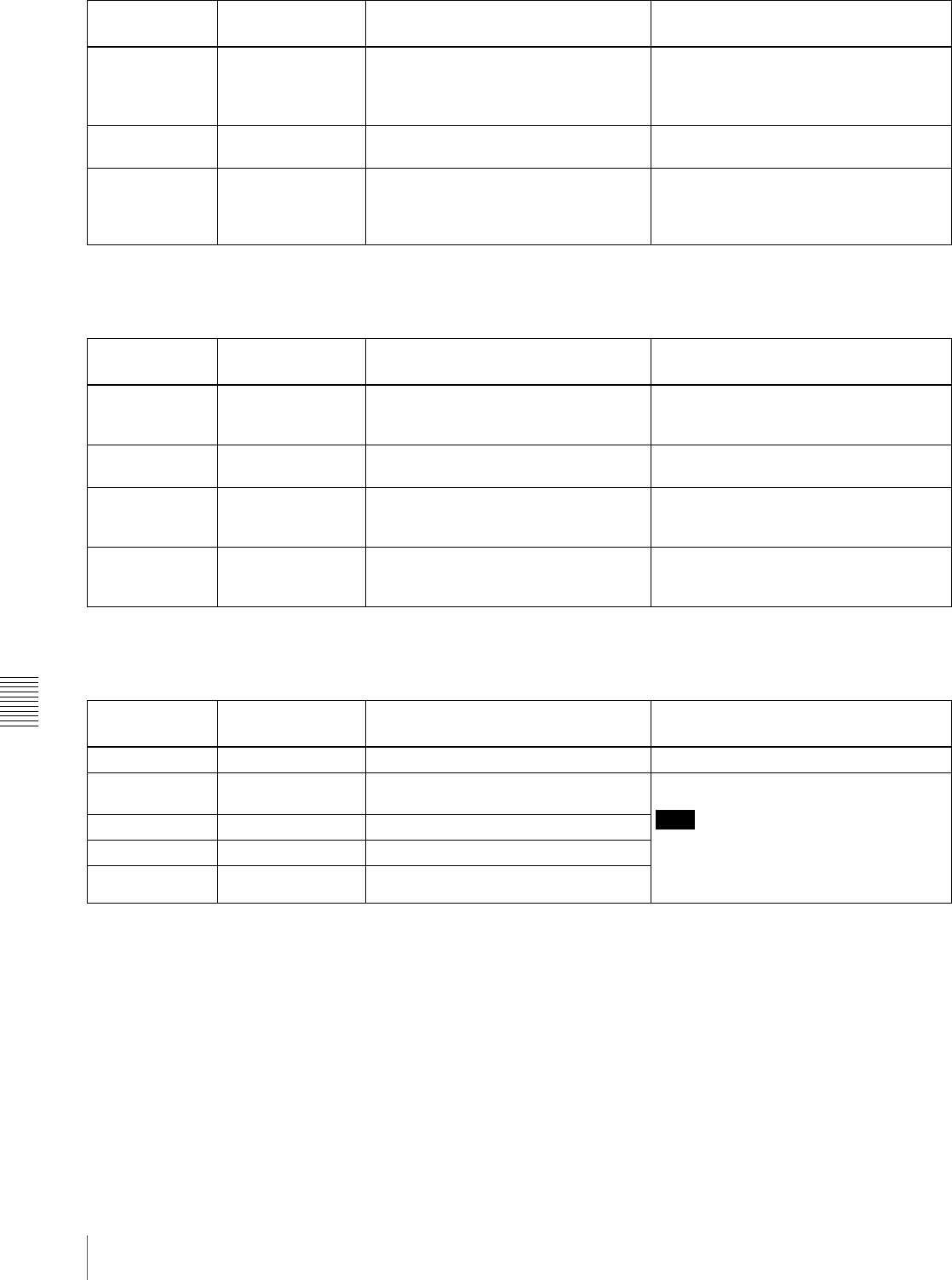
Chapter 8 Maintenance and Troubleshooting
130 8-4 Alarms
a) With respect to setting of basic menu item 016
Alarms relating to audio and video signals
a) With respect to setting of basic menu item 016
Alarms relating to sensors and drives
a) With respect to setting of basic menu item 016
List Exists on, limit, off An attempt was made to edit a clip
referenced by sub clips. Delete all clip lists.
See 5-3-2 “Deleting Clip Lists From a Disc”
(page 69).
Clip End! on, limit, off An attempt was made to edit across clip
boundaries. Editing across multiple clips is not possible.
Recording on, limit More time than normal is required for
recording processing, because
recording is being done while avoiding
defects on the disc.
Wait until recording finishes.
Message in time
data display
Display
condition a)
Description Action
Message in time
data display
Display
condition a)
Description Action
REF NON-STD on, limit, off A signal other than a standard reference
video signal was input to the REF
VIDEO IN connector.
Input a standard reference video signal to
the REF VIDEO IN connector.
No INPUT! on An attempt to record was made with no
input video signal. Input a video signal, and select it.
VIN NON-STD on Recording is being done with a signal
other than a standard video signal input
to the VIDEO IN connector.
Input a standard video signal to the VIDEO
IN connector.
EMPHASIS! on An unsupported audio emphasis signal
(“EMPHASIS ON” signal) was input. This unit does not support “EMPHASIS
ON” audio signals. Input “EMPHASIS OFF”
signal.
Message in time
data display
Display
condition a)
Description Action
HUMID! on, limit, off Condensation was detected in the unit. See 8-2 “Condensation” (page 121).
FAN Stopped on, limit, off The motor of the main unit fan has
stopped. Contact your Sony service representative.
Note
The unit will operate, but continued use in
this state will result in rising temperatures
in the unit or drive, with the risk of fire or
damage to the unit.
DR-FAN Stop on, limit, off The motor of a drive fan has stopped.
High TEMP! on, limit, off Temperatures have risen within the unit.
High TEMP! on, limit, off Temperatures have risen within a drive.
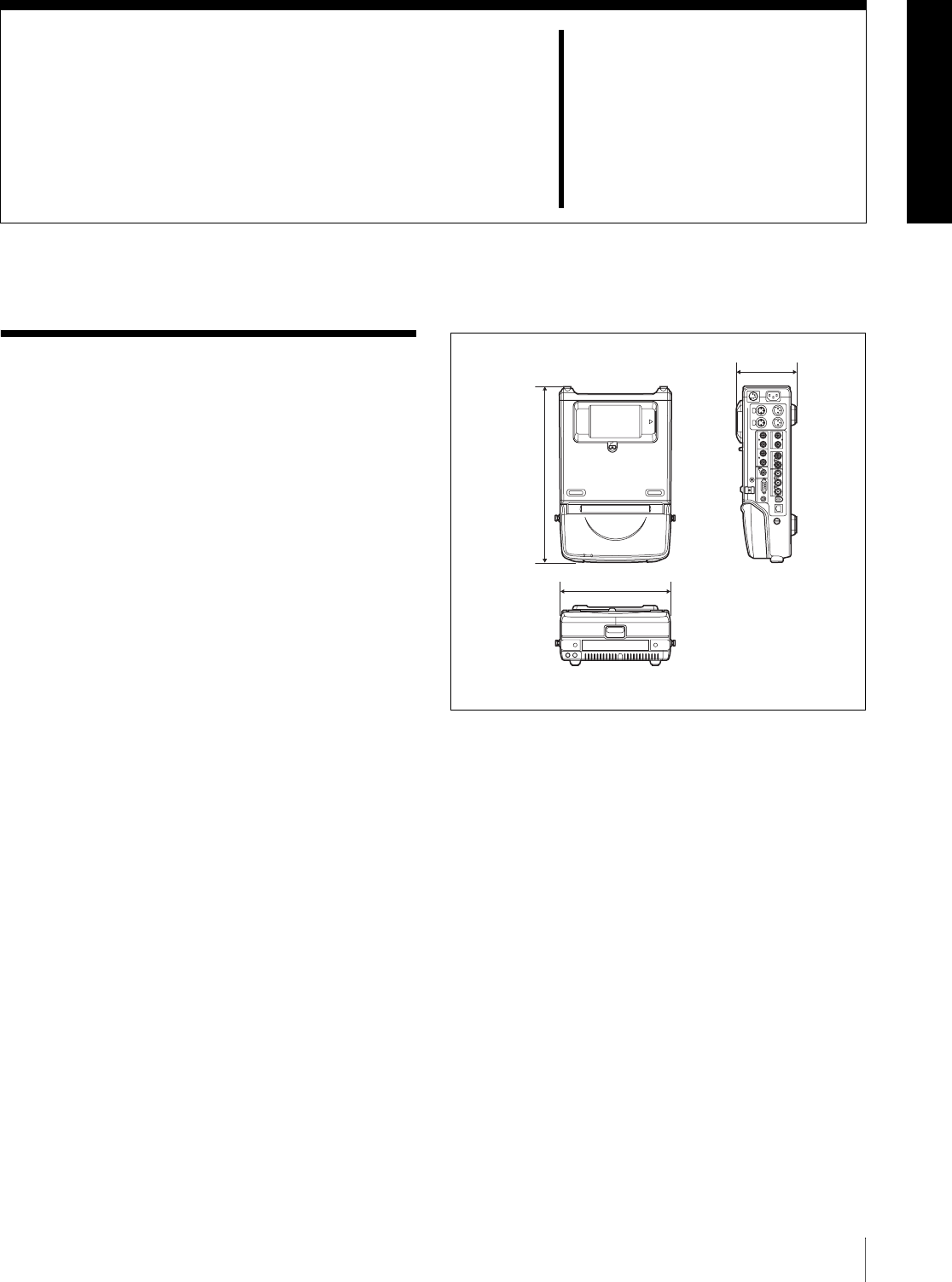
131
Specifications
Appendixes
Specifications
General
Power requirements
100 V to 240 V AC, 50/60 Hz
DC, battery
Power consumption
AC: 37W
DC or battery: 31W
Peak inrush current
(1)Power ON, current probe method: 65
A (240 V), 30 A (100 V)
(2)Hot switching inrush current,
measured in accordance with
European standard EN55103-1: 35 A
(230 V)
Operating temperature
0ºC to 40ºC (32ºF to 104ºF)
Storage temperature
–20ºC to +60ºC (–4ºF to +140ºF)
Operating relative humidity
20% to 90%
Mass 4.7 kg (10 lb 5 oz)
External dimensions (w/h/d, excluding projections)
230 × 105 × 340mm
(91/8 × 41/4 × 131/2 inches)
System
Recording/Playback format
Video MPEG IMX (50/40/30 Mbps), DVCAM
(25 Mbps)
Proxy video
MPEG-4 1)
Audio MPEG IMX: 16 bits/48 kHz (8 channels)
or 24 bits/48 kHz (4 channels)
DVCAM: 16 bits/48 kHz (4 channels)
Proxy audio
A-law (8/4 channels, 8 bits, 8 kHz)
1) The MPEG-4 Codec is a product of Ingenient Technologies, Inc.
Recording/Playback time
MPEG IMX
50 Mbps: 45 min.
40 Mbps: 55 min.
30 Mbps: 68 min.
DVCAM 85 min.
Search speed
Jog mode
340 (13 1/2)
230 (9 1/8)
Unit: mm (inches)
105 (4 1/4)

Appendixes
132 Specifications
±1 times normal speed
Shuttle mode
±20 times normal speed
Video performance
Sampling frequency
Y: 13.5 MHz, R–Y/B–Y: 6.75 MHz
Quantization 10 bits/sample
Analog composite input to analog composite output
Bandwidth: 30 Hz to 4.5 MHz +0.5/–1.5
dB (NTSC), 25 Hz to 5.5 MHz +0.5/–
1.5 dB (PAL)
S/N ratio: 53 dB or more
Differential gain: 2% or less
Differential phase: 2° or less
Y/C delay: 20 ns or less
K-factor (2T pulse): 2% or less
Processor adjustment range
Video level –∞ to +3 dB
Chroma level –∞ to +3 dB
Set up/black level
±30 IRE/±210 mV
Chroma phase/hue
±30°
System sync phase
±3 µs
System SC phase
±200 ns
Audio performance
Frequency response
20 Hz to 20 kHz +0.5/–1.0 dB (0 dB at 1
kHz)
Dynamic range More than 90 dB
Distortion Less than 0.05% (at 1kHz)
Head room 20/18/16/12 dB (Selectable with menu)
Input connectors
Digital signal inputs
SDI IN BNC type (×1)
SDI format (270 Mbps), SMPTE 259M/
CCIR656-III
DIGITAL AUDIO (AES/EBU) IN 1/2, 3/4
BNC type (×2), complying with AES-
3id-1995
S400 (i.LINK)
6-pin (×1), complying with IEEE 1394
Analog video inputs
REF VIDEO IN
BNC type (×1)
Black burst
0.286 V (NTSC), 0.3V (PAL), 75 Ω,
negative sync
Composite sync
VIDEO IN BNC type (×1), composite
1.0 Vp-p, 75 Ω, negative sync
Analog audio inputs
AUDIO IN 1/3, 2/4
XLR 3-pin, female (×2), +4/0/–3/–6 dBu
(selectable with menu), 10 kΩ,
balanced
Time code input
TC IN BNC type (×1), SMPTE time code, 0.5
Vp-p to 18 Vp-p, 3.3 kΩ, unbalanced
(network)
100Base-TX/10Base-T
RJ-45 type (×1)
100BASE-TX: complying with IEEE
802.3u
10BASE-T: complying with IEEE 802.3
Output connectors
Digital signal outputs
SDI OUT (SUPER)
BNC type (×1)
SDI format (270 Mbps), SMPTE 259M/
CCIR656-III
DIGITAL AUDIO (AES/EBU) OUT 1/2, 3/4
BNC type (×2), complying with AES-
3id-1995
S400 (i.LINK)
6-pin (×1), complying with IEEE 1394
Analog video outputs
VIDEO OUT 1, 2(SUPER)
BNC type (×2), composite, 1.0 Vp-p,
75 Ω, sync negative
Analog audio outputs
AUDIO OUT 1/3, 2/4
XLR 3-pin, male (×2), +4/0/–3/–6 dBu
(selectable with menu), 600 Ω loading,
low impedance, balanced
Output for headphones
PHONES JM-60 Stereo phone jack (×1), –∞ to –13
dBu, 8 Ω, unbalanced
Time code output
TC OUT BNC type (×1), SMPTE time code, 2.2
Vp-p ±3 dB, 600 Ω, unbalanced
Remote control connectors
REMOTE D-sub 9-pin (×1), for connection of
editing control unit, RS-422A standard

Appendixes
133
Specifications
S400 (i.LINK)
6-pin (×1), complying with IEEE 1394,
supporting file access mode
Power input/output connectors
DC IN 12V XLR 4-pin, male (×1), 11 to 17 V DC
DC OUT 12V 1)
Round type 4-pin, female (×1)
When driven by AC power: DC 14.5 V,
Max. 5W
When driven by DC power or battery: DC
11 to 17 V, Max. 5W
1) Use as power source for BVR-3 Remote Control Unit (not supplied) and
RM-280 Editing Controller (not supplied).
Others
Video panel Picture: 3.5 type
Pixel resolution: 211,200 pixels (960
wide × 220 high)
Effective picture elements: more than
99.99%
Accessories supplied
Operation manuals
English version (1)
Japanese version (1)
CD-ROM manual (1)
PDZ-1 Proxy Browsing Software (1)
Connector caps For ~AC IN/DC IN 12V connector (1)
For AUDIO IN connectors (2)
For AUDIO OUT connectors (2)
For BNC connectors (12)
For / S400 (i.LINK) connector (1)
For REMOTE connector (1)
For DC OUT 12V connector (1)
Accessories not supplied
AC power cord
• For the customers in the U.S.A and Canada
Part No. 1-551-812-41 (125 V, 10 A, about 2.4 m)
• For the customers in the United Kingdom
Part No. 1-777-823-12 (250 V, 10 A, about 2.0 m)
• For the customers in European countries other than the
United Kingdom
Part No. 1-551-631-61 (250 V, 10 A, about 2.0 m)
Shoulder strap (Part No. A-6772-374-C)
Related products
Battery packs
BP-GL95, BP-GL65, BP-L80S, BP-
L60S
RM-280 editing controller
Design and specifications are subject to change without
notice.
Notes
• Always make a test recording, and verify that it was
recorded successfully.
SONY WILL NOT BE LIABLE FOR DAMAGES OF ANY
KIND INCLUDING, BUT NOT LIMITED TO,
COMPENSATION OR REIMBURSEMENT ON
ACCOUNT OF FAILURE OF THIS UNIT OR ITS
RECORDING MEDIA, EXTERNAL STORAGE SYSTEMS
OR ANY OTHER MEDIA OR STORAGE SYSTEMS TO
RECORD CONTENT OF ANY TYPE.
• Always verify that the unit is operating properly before
use. SONY WILL NOT BE LIABLE FOR DAMAGES OF
ANY KIND INCLUDING, BUT NOT LIMITED TO,
COMPENSATION OR REIMBURSEMENT ON
ACCOUNT OF THE LOSS OF PRESENT OR
PROSPECTIVE PROFITS DUE TO FAILURE OF THIS
UNIT, EITHER DURING THE WARRANTY PERIOD OR
AFTER EXPIRATION OF THE WARRANTY, OR FOR
ANY OTHER REASON WHATSOEVER.
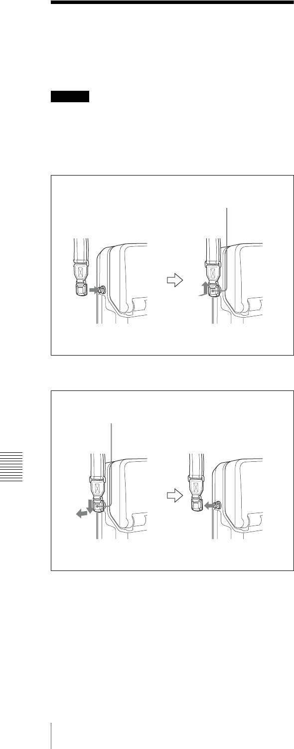
Appendixes
134 Using the Shoulder Belt
Using the Shoulder Belt
The following figures show how to fit the shoulder belt
(not supplied).
Caution
If you fit the shoulder belt incorrectly, the unit may fall
down and cause body injury. Follow the procedures
described below to fit or remove the shoulder belt.
To fit the shoulder belt
To remove the shoulder belt
Press and pull up.
While pressing down the indication PRESS, move the
clip downwards to release it.

Appendixes
135
Notice Concerning the Software License of This Unit
Notice Concerning the Software License of This Unit
Thank you for your purchasing this Sony product. Please read the following notice before using the product. By installing,
copying or otherwise using the product, you will be deemed to have understood and agreed to the content of the notice.
Notice Concerning Software Governed by the GNU GPL/LGPL
This product includes software to which the GNU General Public License (“GPL”) or GNU Lesser General Public License
(“LGPL”) applies. Under the terms of the GPL/LGPL, of which a copy is attached, you have the right to obtain, modify,
and distribute copies of the source code of this software.
Specific instructions for downloading the source code can be found at the following URL:
http://www.sony.net/Products/Linux/
Please note that we cannot respond to inquiries regarding the content of the source code.
GNU GENERAL PUBLIC LICENSE
Version 2, June 1991
Copyright © 1989, 1991 Free Software Foundation, Inc.
59 Temple Place, Suite 330, Boston, MA 02111-1307 USA
Everyone is permitted to copy and distribute verbatim copies of this license document, but changing it is not allowed.
Preamble
The licenses for most software are designed to take away your freedom to share and change it. By contrast, the GNU
General Public License is intended to guarantee your freedom to share and change free software-to make sure the software
is free for all its users. This General Public License applies to most of the Free Software Foundation’s software and to any
other program whose authors commit to using it. (Some other Free Software Foundation software is covered by the GNU
Library General Public License instead.) You can apply it to your programs, too.
When we speak of free software, we are referring to freedom, not price. Our General Public Licenses are designed to make
sure that you have the freedom to distribute copies of free software (and charge for this service if you wish), that you
receive source code or can get it if you want it, that you can change the software or use pieces of it in new free programs;
and that you know you can do these things.
To protect your rights, we need to make restrictions that forbid anyone to deny you these rights or to ask you to surrender
the rights.
These restrictions translate to certain responsibilities for you if you distribute copies of the software, or if you modify it.
For example, if you distribute copies of such a program, whether gratis or for a fee, you must give the recipients all the
rights that you have. You must make sure that they, too, receive or can get the source code. And you must show them these
terms so they know their rights.
We protect your rights with two steps: (1) copyright the software, and (2) offer you this license which gives you legal
permission to copy, distribute and/or modify the software.
Also, for each author’s protection and ours, we want to make certain that everyone understands that there is no warranty
for this free software. If the software is modified by someone else and passed on, we want its recipients to know that what
they have is not the original, so that any problems introduced by others will not reflect on the original authors’ reputations.
Finally, any free program is threatened constantly by software patents. We wish to avoid the danger that redistributors of
a free program will individually obtain patent licenses, in effect making the program proprietary. To prevent this, we have
made it clear that any patent must be licensed for everyone’s free use or not licensed at all.
The precise terms and conditions for copying, distribution and modification follow.

Appendixes
136 Notice Concerning the Software License of This Unit
GNU GENERAL PUBLIC LICENSE
TERMS AND CONDITIONS FOR COPYING, DISTRIBUTION AND MODIFICATION
0. This License applies to any program or other work which contains a notice placed by the copyright holder saying it
may be distributed under the terms of this General Public License. The “Program”, below, refers to any such program
or work, and a “work based on the Program” means either the Program or any derivative work under copyright law:
that is to say, a work containing the Program or a portion of it, either verbatim or with modifications and/or translated
into another language. (Hereinafter, translation is included without limitation in the term “modification”.)
Each licensee is addressed as “you”.
Activities other than copying, distribution and modification are not covered by this License; they are outside its scope.
The act of running the Program is not restricted, and the output from the Program is covered only if its contents
constitute a work based on the Program (independent of having been made by running the Program).
Whether that is true depends on what the Program does.
1. You may copy and distribute verbatim copies of the Program’s source code as you receive it, in any medium, provided
that you conspicuously and appropriately publish on each copy an appropriate copyright notice and disclaimer of
warranty; keep intact all the notices that refer to this License and to the absence of any warranty; and give any other
recipients of the Program a copy of this License along with the Program.
You may charge a fee for the physical act of transferring a copy, and you may at your option offer warranty protection
in exchange for a fee.
2. You may modify your copy or copies of the Program or any portion of it, thus forming a work based on the Program,
and copy and distribute such modifications or work under the terms of Section 1 above, provided that you also meet
all of these conditions:
a) You must cause the modified files to carry prominent notices stating that you changed the files and the date of any
change.
b) You must cause any work that you distribute or publish, that in whole or in part contains or is derived from the
Program or any part thereof, to be licensed as a whole at no charge to all third parties under the terms of this License.
c) If the modified program normally reads commands interactively when run, you must cause it, when started running
for such interactive use in the most ordinary way, to print or display an announcement including an appropriate
copyright notice and a notice that there is no warranty (or else, saying that you provide a warranty) and that users
may redistribute the program under these conditions, and telling the user how to view a copy of this License.
(Exception: if the Program itself is interactive but does not normally print such an announcement, your work based
on the Program is not required to print an announcement.)
These requirements apply to the modified work as a whole. If identifiable sections of that work are not derived from
the Program, and can be reasonably considered independent and separate works in themselves, then this License, and
its terms, do not apply to those sections when you distribute them as separate works. But when you distribute the same
sections as part of a whole which is a work based on the Program, the distribution of the whole must be on the terms
of this License, whose permissions for other licensees extend to the entire whole, and thus to each and every part
regardless of who wrote it.
Thus, it is not the intent of this section to claim rights or contest your rights to work written entirely by you; rather,
the intent is to exercise the right to control the distribution of derivative or collective works based on the Program.
In addition, mere aggregation of another work not based on the Program with the Program (or with a work based on
the Program) on a volume of a storage or distribution medium does not bring the other work under the scope of this
License.
3. You may copy and distribute the Program (or a work based on it, under Section 2) in object code or executable form
under the terms of Sections 1 and 2 above provided that you also do one of the following:

Appendixes
137
Notice Concerning the Software License of This Unit
a) Accompany it with the complete corresponding machine-readable source code, which must be distributed under the
terms of Sections 1 and 2 above on a medium customarily used for software interchange; or,
b) Accompany it with a written offer, valid for at least three years, to give any third party, for a charge no more than
your cost of physically performing source distribution, a complete machine-readable copy of the corresponding
source code, to be distributed under the terms of Sections 1 and 2 above on a medium customarily used for software
interchange; or,
c) Accompany it with the information you received as to the offer to distribute corresponding source code. (This
alternative is allowed only for noncommercial distribution and only if you received the program in object code or
executable form with such an offer, in accord with Subsection b above.)
The source code for a work means the preferred form of the work for making modifications to it. For an executable
work, complete source code means all the source code for all modules it contains, plus any associated interface
definition files, plus the scripts used to control compilation and installation of the executable. However, as a special
exception, the source code distributed need not include anything that is normally distributed (in either source or binary
form) with the major components (compiler, kernel, and so on) of the operating system on which the executable runs,
unless that component itself accompanies the executable.
If distribution of executable or object code is made by offering access to copy from a designated place, then offering
equivalent access to copy the source code from the same place counts as distribution of the source code, even though
third parties are not compelled to copy the source along with the object code.
4. You may not copy, modify, sublicense, or distribute the Program except as expressly provided under this License. Any
attempt otherwise to copy, modify, sublicense or distribute the Program is void, and will automatically terminate your
rights under this License.
However, parties who have received copies, or rights, from you under this License will not have their licenses
terminated so long as such parties remain in full compliance.
5. You are not required to accept this License, since you have not signed it. However, nothing else grants you permission
to modify or distribute the Program or its derivative works. These actions are prohibited by law if you do not accept
this License. Therefore, by modifying or distributing the Program (or any work based on the Program), you indicate
your acceptance of this License to do so, and all its terms and conditions for copying, distributing or modifying the
Program or works based on it.
6. Each time you redistribute the Program (or any work based on the Program), the recipient automatically receives a
license from the original licensor to copy, distribute or modify the Program subject to these terms and conditions. You
may not impose any further restrictions on the recipients’ exercise of the rights granted herein.
You are not responsible for enforcing compliance by third parties to this License.
7. If, as a consequence of a court judgment or allegation of patent infringement or for any other reason (not limited to
patent issues), conditions are imposed on you (whether by court order, agreement or otherwise) that contradict the
conditions of this License, they do not excuse you from the conditions of this License. If you cannot distribute so as
to satisfy simultaneously your obligations under this License and any other pertinent obligations, then as a
consequence you may not distribute the Program at all. For example, if a patent license would not permit royalty-free
redistribution of the Program by all those who receive copies directly or indirectly through you, then the only way you
could satisfy both it and this License would be to refrain entirely from distribution of the Program.
If any portion of this section is held invalid or unenforceable under any particular circumstance, the balance of the
section is intended to apply and the section as a whole is intended to apply in other circumstances.
It is not the purpose of this section to induce you to infringe any patents or other property right claims or to contest
validity of any such claims; this section has the sole purpose of protecting the integrity of the free software distribution
system, which is implemented by public license practices. Many people have made generous contributions to the wide
range of software distributed through that system in reliance on consistent application of that system; it is up to the
author/donor to decide if he or she is willing to distribute software through any other system and a licensee cannot
impose that choice.

Appendixes
138 Notice Concerning the Software License of This Unit
This section is intended to make thoroughly clear what is believed to be a consequence of the rest of this License.
8. If the distribution and/or use of the Program is restricted in certain countries either by patents or by copyrighted
interfaces, the original copyright holder who places the Program under this License may add an explicit geographical
distribution limitation excluding those countries, so that distribution is permitted only in or among countries not thus
excluded. In such case, this License incorporates the limitation as if written in the body of this License.
9. The Free Software Foundation may publish revised and/or new versions of the General Public License from time to
time. Such new versions will be similar in spirit to the present version, but may differ in detail to address new problems
or concerns.
Each version is given a distinguishing version number. If the Program specifies a version number of this License which
applies to it and “any later version”, you have the option of following the terms and conditions either of that version
or of any later version published by the Free Software Foundation. If the Program does not specify a version number
of this License, you may choose any version ever published by the Free Software Foundation.
10. If you wish to incorporate parts of the Program into other free programs whose distribution conditions are different,
write to the author to ask for permission. For software which is copyrighted by the Free Software Foundation, write
to the Free Software Foundation; we sometimes make exceptions for this. Our decision will be guided by the two goals
of preserving the free status of all derivatives of our free software and of promoting the sharing and reuse of software
generally.
NO WARRANTY
11. BECAUSE THE PROGRAM IS LICENSED FREE OF CHARGE, THERE IS NO WARRANTY FOR THE
PROGRAM, TO THE EXTENT PERMITTED BY APPLICABLE LAW. EXCEPT WHEN OTHERWISE STATED
IN WRITING THE COPYRIGHT HOLDERS AND/OR OTHER PARTIES PROVIDE THE PROGRAM “AS IS”
WITHOUT WARRANTY OF ANY KIND, EITHER EXPRESSED OR IMPLIED, INCLUDING, BUT NOT
LIMITED TO, THE IMPLIED WARRANTIES OF MERCHANTABILITY AND FITNESS FOR A PARTICULAR
PURPOSE. THE ENTIRE RISK AS TO THE QUALITY AND PERFORMANCE OF THE PROGRAM IS WITH
YOU. SHOULD THE PROGRAM PROVE DEFECTIVE, YOU ASSUME THE COST OF ALL NECESSARY
SERVICING,REPAIR OR CORRECTION.
12. IN NO EVENT UNLESS REQUIRED BY APPLICABLE LAW OR AGREED TO IN WRITING WILL ANY
COPYRIGHT HOLDER, OR ANY OTHER PARTY WHO MAY MODIFY AND/OR REDISTRIBUTE THE
PROGRAM AS PERMITTED ABOVE, BE LIABLE TO YOU FOR DAMAGES, INCLUDING ANY GENERAL,
SPECIAL, INCIDENTAL OR CONSEQUENTIAL DAMAGES ARISING OUT OF THE USE OR INABILITY TO
USE THE PROGRAM (INCLUDING BUT NOT LIMITED TO LOSS OF DATA OR DATA BEING RENDERED
INACCURATE OR LOSSES SUSTAINED BY YOU OR THIRD PARTIES OR A FAILURE OF THE PROGRAM
TO OPERATE WITH ANY OTHER PROGRAMS), EVEN IF SUCH HOLDER OR OTHER PARTY HAS BEEN
ADVISED OF THE POSSIBILITY OF SUCH DAMAGES.
END OF TERMS AND CONDITIONS
How to Apply These Terms to Your New Programs
If you develop a new program, and you want it to be of the greatest possible use to the public, the best way to achieve this
is to make it free software which everyone can redistribute and change under these terms.
To do so, attach the following notices to the program. It is safest to attach them to the start of each source file to most
effectively convey the exclusion of warranty; and each file should have at least the “copyright” line and a pointer to where
the full notice is found.
Copyright ©
This program is free software; you can redistribute it and/or modify it under the terms of the GNU General Public License
as published by the Free Software Foundation; either version 2 of the License, or (at your option) any later version.

Appendixes
139
Notice Concerning the Software License of This Unit
This program is distributed in the hope that it will be useful, but WITHOUT ANY WARRANTY; without even the implied
warranty of MERCHANTABILITY or FITNESS FOR A PARTICULAR PURPOSE. See the GNU General Public
License for more details.
You should have received a copy of the GNU General Public License along with this program; if not, write to the Free
Software Foundation, Inc., 59 Temple Place, Suite 330, Boston, MA 02111-1307 USA
Also add information on how to contact you by electronic and paper mail.
If the program is interactive, make it output a short notice like this when it starts in an interactive mode:
Gnomovision version 69, Copyright © year name of author Gnomovision comes with ABSOLUTELY NO WARRANTY;
for details type ‘show w’.
This is free software, and you are welcome to redistribute it under certain conditions; type ‘show c’ for details.
The hypothetical commands ‘show w’ and ‘show c’ should show the appropriate parts of the General Public License. Of
course, the commands you use may be called something other than ‘show w’ and ‘show c’, they could even be mouse-
clicks or menu items-whatever suits your program.
You should also get your employer (if you work as a programmer) or your school, if any, to sign a “copyright disclaimer”
for the program, if necessary. Here is a sample; alter the names:
Yoyodyne, Inc., hereby disclaims all copyright interest in the program ‘Gnomovision’ (which makes passes at compilers)
written by James Hacker.
, 1 April 1989
Ty Coon, President of Vice
This General Public License does not permit incorporating your program into proprietary programs. If your program is a
subroutine library, you may consider it more useful to permit linking proprietary applications with the library. If this is
what you want to do, use the GNU Library General Public License instead of this License.
GNU LESSER GENERAL PUBLIC LICENSE
Version 2.1, February 1999
Copyright © 1991, 1999 Free Software Foundation, Inc.
59 Temple Place, Suite 330, Boston, MA 02111-1307 USA
Everyone is permitted to copy and distribute verbatim copies of this license document, but changing it is not allowed.
[This is the first released version of the Lesser GPL. It also counts as the successor of the GNU Library Public License,
version 2, hence the version number 2.1.]
Preamble
The licenses for most software are designed to take away your freedom to share and change it. By contrast, the GNU
General Public Licenses are intended to guarantee your freedom to share and change free software-to make sure the
software is free for all its users.
This license, the Lesser General Public License, applies to some specially designated software packages-typically
libraries-of the Free Software Foundation and other authors who decide to use it. You can use it too, but we suggest you
first think carefully about whether this license or the ordinary General Public License is the better strategy to use in any
particular case, based on the explanations below.
When we speak of free software, we are referring to freedom of use, not price. Our General Public Licenses are designed
to make sure that you have the freedom to distribute copies of free software (and charge for this service if you wish); that
you receive source code or can get it if you want it; that you can change the software and use pieces of it in new free
programs; and that you are informed that you can do these things.
To protect your rights, we need to make restrictions that forbid distributors to deny you these rights or to ask you to
surrender these rights. These restrictions translate to certain responsibilities for you if you distribute copies of the library
or if you modify it.

Appendixes
140 Notice Concerning the Software License of This Unit
For example, if you distribute copies of the library, whether gratis or for a fee, you must give the recipients all the rights
that we gave you. You must make sure that they, too, receive or can get the source code. If you link other code with the
library, you must provide complete object files to the recipients, so that they can relink them with the library after making
changes to the library and recompiling it. And you must show them these terms so they know their rights.
We protect your rights with a two-step method: (1) we copyright the library, and (2) we offer you this license, which gives
you legal permission to copy, distribute and/or modify the library.
To protect each distributor, we want to make it very clear that there is no warranty for the free library. Also, if the library
is modified by someone else and passed on, the recipients should know that what they have is not the original version, so
that the original author’s reputation will not be affected by problems that might be introduced by others.
Finally, software patents pose a constant threat to the existence of any free program. We wish to make sure that a company
cannot effectively restrict the users of a free program by obtaining a restrictive license from a patent holder. Therefore, we
insist that any patent license obtained for a version of the library must be consistent with the full freedom of use specified
in this license.
Most GNU software, including some libraries, is covered by the ordinary GNU General Public License. This license, the
GNU Lesser General Public License, applies to certain designated libraries, and is quite different from the ordinary
General Public License. We use this license for certain libraries in order to permit linking those libraries into non-free
programs.
When a program is linked with a library, whether statically or using a shared library, the combination of the two is legally
speaking a combined work, a derivative of the original library. The ordinary General Public License therefore permits such
linking only if the entire combination fits its criteria of freedom. The Lesser General Public License permits more lax
criteria for linking other code with the library.
We call this license the “Lesser” General Public License because it does Less to protect the user’s freedom than the
ordinary General Public License. It also provides other free software developers Less of an advantage over competing non-
free programs. These disadvantages are the reason we use the ordinary General Public License for many libraries.
However, the Lesser license provides advantages in certain special circumstances.
For example, on rare occasions, there may be a special need to encourage the widest possible use of a certain library, so
that it becomes a de-facto standard. To achieve this, non-free programs must be allowed to use the library. A more frequent
case is that a free library does the same job as widely used non-free libraries. In this case, there is little to gain by limiting
the free library to free software only, so we use the Lesser General Public License.
In other cases, permission to use a particular library in non-free programs enables a greater number of people to use a large
body of free software. For example, permission to use the GNU C Library in non-free programs enables many more people
to use the whole GNU operating system, as well as its variant, the GNU/Linux operating system.
Although the Lesser General Public License is Less protective of the users’ freedom, it does ensure that the user of a
program that is linked with the Library has the freedom and the wherewithal to run that program using a modified version
of the Library.The precise terms and conditions for copying, distribution and modification follow. Pay close attention to
the difference between a “work based on the library” and a “work that uses the library”. The former contains code derived
from the library, whereas the latter must be combined with the library in order to run.
GNU LESSER GENERAL PUBLIC LICENSE
TERMS AND CONDITIONS FOR COPYING, DISTRIBUTION AND MODIFICATION
0. This License Agreement applies to any software library or other program which contains a notice placed by the
copyright holder or other authorized party saying it may be distributed under the terms of this Lesser General Public
License (also called “this License”). Each licensee is addressed as “you”.
A “library” means a collection of software functions and/or data prepared so as to be conveniently linked with application
programs (which use some of those functions and data) to form executables.

Appendixes
141
Notice Concerning the Software License of This Unit
The “Library”, below, refers to any such software library or work which has been distributed under these terms. A “work
based on the Library” means either the Library or any derivative work under copyright law: that is to say, a work
containing the Library or a portion of it, either verbatim or with modifications and/or translated straightforwardly into
another language. (Hereinafter, translation is included without limitation in the term “modification”.)
“Source code” for a work means the preferred form of the work for making modifications to it. For a library, complete
source code means all the source code for all modules it contains, plus any associated interface definition files, plus the
scripts used to control compilation and installation of the library.
Activities other than copying, distribution and modification are not covered by this License; they are outside its scope. The
act of running a program using the Library is not restricted, and output from such a program is covered only if its contents
constitute a work based on the Library (independent of the use of the Library in a tool for writing it). Whether that is true
depends on what the Library does and what the program that uses the Library does.
1. You may copy and distribute verbatim copies of the Library’s complete source code as you receive it, in any medium,
provided that you conspicuously and appropriately publish on each copy an appropriate copyright notice and
disclaimer of warranty; keep intact all the notices that refer to this License and to the absence of any warranty; and
distribute a copy of this License along with the Library.
You may charge a fee for the physical act of transferring a copy, and you may at your option offer warranty protection
in exchange for a fee.
2. You may modify your copy or copies of the Library or any portion of it, thus forming a work based on the Library,
and copy and distribute such modifications or work under the terms of Section 1 above, provided that you also meet
all of these conditions:
a) The modified work must itself be a software library.
b) You must cause the files modified to carry prominent notices stating that you changed the files and the date of any
change.
c) You must cause the whole of the work to be licensed at no charge to all third parties under the terms of this License.
d) If a facility in the modified Library refers to a function or a table of data to be supplied by an application program
that uses the facility, other than as an argument passed when the facility is invoked, then you must make a good
faith effort to ensure that, in the event an application does not supply such function or table, the facility still operates,
and performs whatever part of its purpose remains meaningful.
(For example, a function in a library to compute square roots has a purpose that is entirely well-defined independent
of the application. Therefore, Subsection 2d requires that any application-supplied function or table used by this
function must be optional: if the application does not supply it, the square root function must still compute square
roots.)
These requirements apply to the modified work as a whole. If identifiable sections of that work are not derived from
the Library, and can be reasonably considered independent and separate works in themselves, then this License, and
its terms, do not apply to those sections when you distribute them as separate works. But when you distribute the same
sections as part of a whole which is a work based on the Library, the distribution of the whole must be on the terms of
this License, whose permissions for other licensees extend to the entire whole, and thus to each and every part
regardless of who wrote it.
Thus, it is not the intent of this section to claim rights or contest your rights to work written entirely by you; rather,
the intent is to exercise the right to control the distribution of derivative or collective works based on the Library.
In addition, mere aggregation of another work not based on the Library with the Library (or with a work based on the
Library) on a volume of a storage or distribution medium does not bring the other work under the scope of this License.

Appendixes
142 Notice Concerning the Software License of This Unit
3. You may opt to apply the terms of the ordinary GNU General Public License instead of this License to a given copy
of the Library. To do this, you must alter all the notices that refer to this License, so that they refer to the ordinary GNU
General Public License, version 2, instead of to this License. (If a newer version than version 2 of the ordinary GNU
General Public License has appeared, then you can specify that version instead if you wish.) Do not make any other
change in these notices.
Once this change is made in a given copy, it is irreversible for that copy, so the ordinary GNU General Public License
applies to all subsequent copies and derivative works made from that copy.
This option is useful when you wish to copy part of the code of the Library into a program that is not a library.
4. You may copy and distribute the Library (or a portion or derivative of it, under Section 2) in object code or executable
form under the terms of Sections 1 and 2 above provided that you accompany it with the complete corresponding
machine-readable source code, which must be distributed under the terms of Sections 1 and 2 above on a medium
customarily used for software interchange.
If distribution of object code is made by offering access to copy from a designated place, then offering equivalent
access to copy the source code from the same place satisfies the requirement to distribute the source code, even though
third parties are not compelled to copy the source along with the object code.
5. A program that contains no derivative of any portion of the Library, but is designed to work with the Library by being
compiled or linked with it, is called a “work that uses the Library”. Such a work, in isolation, is not a derivative work
of the Library, and therefore falls outside the scope of this License.
However, linking a “work that uses the Library” with the Library creates an executable that is a derivative of the
Library (because it contains portions of the Library), rather than a “work that uses the library”. The executable is
therefore covered by this License. Section 6 states terms for distribution of such executables.
When a “work that uses the Library” uses material from a header file that is part of the Library, the object code for the
work may be a derivative work of the Library even though the source code is not. Whether this is true is especially
significant if the work can be linked without the Library, or if the work is itself a library. The threshold for this to be
true is not precisely defined by law.
If such an object file uses only numerical parameters, data structure layouts and accessors, and small macros and small
inline functions (ten lines or less in length), then the use of the object file is unrestricted, regardless of whether it is
legally a derivative work. (Executables containing this object code plus portions of the Library will still fall under
Section 6.)
Otherwise, if the work is a derivative of the Library, you may distribute the object code for the work under the terms
of Section 6. Any executables containing that work also fall under Section 6, whether or not they are linked directly
with the Library itself.
6. As an exception to the Sections above, you may also combine or link a “work that uses the Library” with the Library
to produce a work containing portions of the Library, and distribute that work under terms of your choice, provided
that the terms permit modification of the work for the customer’s own use and reverse engineering for debugging such
modifications.
You must give prominent notice with each copy of the work that the Library is used in it and that the Library and its
use are covered by this License. You must supply a copy of this License. If the work during execution displays
copyright notices, you must include the copyright notice for the Library among them, as well as a reference directing
the user to the copy of this License. Also, you must do one of these things:
a) Accompany the work with the complete corresponding machine-readable source code for the Library including
whatever changes were used in the work (which must be distributed under Sections 1 and 2 above); and, if the work
is an executable linked with the Library, with the complete machine-readable “work that uses the Library”, as object
code and/or source code, so that the user can modify the Library and then relink to produce a modified executable

Appendixes
143
Notice Concerning the Software License of This Unit
containing the modified Library. (It is understood that the user who changes the contents of definitions files in the
Library will not necessarily be able to recompile the application to use the modified definitions.)
b) Use a suitable shared library mechanism for linking with the Library. A suitable mechanism is one that (1) uses at
run time a copy of the library already present on the user’s computer system, rather than copying library functions
into the executable, and (2) will operate properly with a modified version of the library, if the user installs one, as
long as the modified version is interface-compatible with the version that the work was made with.
c) Accompany the work with a written offer, valid for at least three years, to give the same user the materials specified
in Subsection 6a, above, for a charge no more than the cost of performing this distribution.
d) If distribution of the work is made by offering access to copy from a designated place, offer equivalent access to
copy the above specified materials from the same place.
e) Verify that the user has already received a copy of these materials or that you have already sent this user a copy.
For an executable, the required form of the “work that uses the Library” must include any data and utility programs
needed for reproducing the executable from it. However, as a special exception, the materials to be distributed need
not include anything that is normally distributed (in either source or binary form) with the major components
(compiler, kernel, and so on) of the operating system on which the executable runs, unless that component itself
accompanies the executable.
It may happen that this requirement contradicts the license restrictions of other proprietary libraries that do not
normally accompany the operating system. Such a contradiction means you cannot use both them and the Library
together in an executable that you distribute.
7. You may place library facilities that are a work based on the Library side-by-side in a single library together with other
library facilities not covered by this License, and distribute such a combined library, provided that the separate
distribution of the work based on the Library and of the other library facilities is otherwise permitted, and provided
that you do these two things:
a) Accompany the combined library with a copy of the same work based on the Library, uncombined with any other
library facilities. This must be distributed under the terms of the Sections above.
b) Give prominent notice with the combined library of the fact that part of it is a work based on the Library, and
explaining where to find the accompanying uncombined form of the same work.
8. You may not copy, modify, sublicense, link with, or distribute the Library except as expressly provided under this
License. Any attempt otherwise to copy, modify, sublicense, link with, or distribute the Library is void, and will
automatically terminate your rights under this License.
However, parties who have received copies, or rights, from you under this License will not have their licenses
terminated so long as such parties remain in full compliance.
9. You are not required to accept this License, since you have not signed it. However, nothing else grants you permission
to modify or distribute the Library or its derivative works. These actions are prohibited by law if you do not accept
this License. Therefore, by modifying or distributing the Library (or any work based on the Library), you indicate your
acceptance of this License to do so, and all its terms and conditions for copying, distributing or modifying the Library
or works based on it.
10. Each time you redistribute the Library (or any work based on the Library), the recipient automatically receives a
license from the original licensor to copy, distribute, link with or modify the Library subject to these terms and
conditions. You may not impose any further restrictions on the recipients’ exercise of the rights granted herein. You
are not responsible for enforcing compliance by third parties with this License.
11. If, as a consequence of a court judgment or allegation of patent infringement or for any other reason (not limited to
patent issues), conditions are imposed on you (whether by court order, agreement or otherwise) that contradict the
conditions of this License, they do not excuse you from the conditions of this License. If you cannot distribute so as

Appendixes
144 Notice Concerning the Software License of This Unit
to satisfy simultaneously your obligations under this License and any other pertinent obligations, then as a
consequence you may not distribute the Library at all. For example, if a patent license would not permit royalty-free
redistribution of the Library by all those who receive copies directly or indirectly through you, then the only way you
could satisfy both it and this License would be to refrain entirely from distribution of the Library.
If any portion of this section is held invalid or unenforceable under any particular circumstance, the balance of the
section is intended to apply, and the section as a whole is intended to apply in other circumstances.
It is not the purpose of this section to induce you to infringe any patents or other property right claims or to contest
validity of any such claims; this section has the sole purpose of protecting the integrity of the free software distribution
system which is implemented by public license practices. Many people have made generous contributions to the wide
range of software distributed through that system in reliance on consistent application of that system; it is up to the
author/donor to decide if he or she is willing to distribute software through any other system and a licensee cannot
impose that choice.
This section is intended to make thoroughly clear what is believed to be a consequence of the rest of this License.
12. If the distribution and/or use of the Library is restricted in certain countries either by patents or by copyrighted
interfaces, the original copyright holder who places the Library under this License may add an explicit geographical
distribution limitation excluding those countries, so that distribution is permitted only in or among countries not thus
excluded. In such case, this License incorporates the limitation as if written in the body of this License.
13. The Free Software Foundation may publish revised and/or new versions of the Lesser General Public License from
time to time. Such new versions will be similar in spirit to the present version, but may differ in detail to address new
problems or concerns.
Each version is given a distinguishing version number. If the Library specifies a version number of this License which
applies to it and “any later version”, you have the option of following the terms and conditions either of that version
or of any later version published by the Free Software Foundation. If the Library does not specify a license version
number, you may choose any version ever published by the Free Software Foundation.
14. If you wish to incorporate parts of the Library into other free programs whose distribution conditions are incompatible
with these, write to the author to ask for permission. For software which is copyrighted by the Free Software
Foundation, write to the Free Software Foundation; we sometimes make exceptions for this. Our decision will be
guided by the two goals of preserving the free status of all derivatives of our free software and of promoting the sharing
and reuse of software generally.
NO WARRANTY
15. BECAUSE THE LIBRARY IS LICENSED FREE OF CHARGE, THERE IS NO WARRANTY FOR THE
LIBRARY, TO THE EXTENT PERMITTED BY APPLICABLE LAW.
EXCEPT WHEN OTHERWISE STATED IN WRITING THE COPYRIGHT HOLDERS AND/OR OTHER
PARTIES PROVIDE THE LIBRARY “AS IS” WITHOUT WARRANTY OF ANY KIND, EITHER EXPRESSED
OR IMPLIED, INCLUDING, BUT NOT LIMITED TO, THE IMPLIED WARRANTIES OF
MERCHANTABILITY AND FITNESS FOR A PARTICULAR PURPOSE. THE ENTIRE RISK AS TO THE
QUALITY AND PERFORMANCE OF THE LIBRARY IS WITH YOU. SHOULD THE LIBRARY PROVE
DEFECTIVE, YOU ASSUME THE COST OF ALL NECESSARY SERVICING, REPAIR OR CORRECTION.
16. IN NO EVENT UNLESS REQUIRED BY APPLICABLE LAW OR AGREED TO IN WRITING WILL ANY
COPYRIGHT HOLDER, OR ANY OTHER PARTY WHO MAY MODIFY AND/OR REDISTRIBUTE THE
LIBRARY AS PERMITTED ABOVE, BE LIABLE TO YOU FOR DAMAGES, INCLUDING ANY GENERAL,
SPECIAL, INCIDENTAL OR CONSEQUENTIAL DAMAGES ARISING OUT OF THE USE OR INABILITY TO
USE THE LIBRARY (INCLUDING BUT NOT LIMITED TO LOSS OF DATA OR DATA BEING RENDERED
INACCURATE OR LOSSES SUSTAINED BY YOU OR THIRD PARTIES OR A FAILURE OF THE LIBRARY
TO OPERATE WITH ANY OTHER SOFTWARE), EVEN IF SUCH HOLDER OR OTHER PARTY HAS BEEN
ADVISED OF THE POSSIBILITY OF SUCH DAMAGES.

Appendixes
145
Notice Concerning the Software License of This Unit
END OF TERMS AND CONDITIONS
How to Apply These Terms to Your New Libraries
If you develop a new library, and you want it to be of the greatest possible use to the public, we recommend making it free
software that everyone can redistribute and change. You can do so by permitting redistribution under these terms (or,
alternatively, under the terms of the ordinary General Public License).
To apply these terms, attach the following notices to the library. It is safest to attach them to the start of each source file
to most effectively convey the exclusion of warranty; and each file should have at least the “copyright” line and a pointer
to where the full notice is found.
Copyright ©
This library is free software; you can redistribute it and/or modify it under the terms of the GNU Lesser General Public
License as published by the Free Software Foundation; either version 2.1 of the License, or (at your option) any later
version. This library is distributed in the hope that it will be useful, but WITHOUT ANY WARRANTY; without even the
implied warranty of MERCHANTABILITY or FITNESS FOR A PARTICULAR PURPOSE. See the GNU Lesser
General Public License for more details.
You should have received a copy of the GNU Lesser General Public License along with this library; if not, write to the
Free Software Foundation, Inc., 59 Temple Place, Suite 330, Boston, MA 02111-1307 USA
Also add information on how to contact you by electronic and paper mail.
You should also get your employer (if you work as a programmer) or your school, if any, to sign a “copyright disclaimer”
for the library, if necessary.
Here is a sample; alter the names:
Yoyodyne, Inc., hereby disclaims all copyright interest in the library ‘Frob’ (a library for tweaking knobs) written by
James Random Hacker.
, 1 April 1990
Ty Coon, President of Vice
That’s all there is to it!
The BSD Copyright
This product includes software to which the BSD license applies.
Please note that we cannot respond to inquiries regarding the content of the source code.
The BSD License
Copyright © The Regents of the University of California.
All rights reserved.
Redistribution and use in source and binary forms, with or without modification, are permitted provided that the following
conditions are met:
1. Redistributions of source code must retain the above copyright notice, this list of conditions and the following
disclaimer.
2. Redistributions in binary form must reproduce the above copyright notice, this list of conditions and the following
disclaimer in the documentation and/or other materials provided with the distribution.
3. Neither the name of the University nor the names of its contributors may be used to endorse or promote products
derived from this software without specific prior written permission.

Appendixes
146 Notice Concerning the Software License of This Unit
THIS SOFTWARE IS PROVIDED BY THE REGENTS AND CONTRIBUTORS “AS IS” AND ANY EXPRESS OR
IMPLIED WARRANTIES, INCLUDING, BUT NOT LIMITED TO, THE IMPLIED WARRANTIES OF
MERCHANTABILITY AND FITNESS FOR A PARTICULAR PURPOSE ARE DISCLAIMED. IN NO EVENT
SHALL THE REGENTS OR CONTRIBUTORS BE LIABLE FOR ANY DIRECT, INDIRECT, INCIDENTAL,
SPECIAL, EXEMPLARY, OR CONSEQUENTIAL DAMAGES (INCLUDING, BUT NOT LIMITED TO,
PROCUREMENT OF SUBSTITUTE GOODS OR SERVICES; LOSS OF USE, DATA, OR PROFITS; OR BUSINESS
INTERRUPTION) HOWEVER CAUSED AND ON ANY THEORY OF LIABILITY, WHETHER IN CONTRACT,
STRICT LIABILITY, OR TORT (INCLUDING NEGLIGENCE OR OTHERWISE) ARISING IN ANY WAY OUT OF
THE USE OF THIS SOFTWARE, EVEN IF ADVISED OF THE POSSIBILITY OF SUCH DAMAGE.
This product includes software thttpd to which the license below applies.
Please note that we cannot respond to inquiries regarding the content of the source code.
Copyright © 1995, 1998, 1999, 2000, 2001 by Jef Poskanzer <jef@acme.com>.
All rights reserved.
Redistribution and use in source and binary forms, with or without modification, are permitted provided that the following
conditions are met:
1. Redistributions of source code must retain the above copyright notice, this list of conditions and the following
disclaimer.
2. Redistributions in binary form must reproduce the above copyright notice, this list of conditions and the following
disclaimer in the documentation and/or other materials provided with the distribution.
THIS SOFTWARE IS PROVIDED BY THE AUTHOR AND CONTRIBUTORS “AS IS” AND ANY EXPRESS OR
IMPLIED WARRANTIES, INCLUDING, BUT NOT LIMITED TO, THE IMPLIED WARRANTIES OF
MERCHANTABILITY AND FITNESS FOR A PARTICULAR PURPOSE ARE DISCLAIMED. IN NO EVENT
SHALL THE AUTHOR OR CONTRIBUTORS BE LIABLE FOR ANY DIRECT, INDIRECT, INCIDENTAL,
SPECIAL, EXEMPLARY, OR CONSEQUENTIAL DAMAGES (INCLUDING, BUT NOT LIMITED TO,
PROCUREMENT OF SUBSTITUTE GOODS OR SERVICES; LOSS OF USE, DATA, OR PROFITS; OR BUSINESS
INTERRUPTION) HOWEVER CAUSED AND ON ANY THEORY OF LIABILITY, WHETHER IN CONTRACT,
STRICT LIABILITY, OR TORT (INCLUDING NEGLIGENCE OR OTHERWISE) ARISING IN ANY WAY OUT OF
THE USE OF THIS SOFTWARE, EVEN IF ADVISED OF THE POSSIBILITY OF SUCH DAMAGE.
This product includes software ucd-snmp to which the license below applies.
Please note that we cannot respond to inquiries regarding the content of the source code.
----- Part 1: CMU/UCD copyright notice: (BSD like) -----
Copyright 1989, 1991, 1992 by Carnegie Mellon University
Derivative Work - 1996, 1998-2000
Copyright 1996, 1998-2000 The Regents of the University of California
All Rights Reserved
Permission to use, copy, modify and distribute this software and its documentation for any purpose and without fee is
hereby granted, provided that the above copyright notice appears in all copies and that both that copyright notice and this
permission notice appear in supporting documentation, and that the name of CMU and The Regents of the University of
California not be used in advertising or publicity pertaining to distribution of the software without specific written
permission.
CMU AND THE REGENTS OF THE UNIVERSITY OF CALIFORNIA DISCLAIM ALL WARRANTIES WITH
REGARD TO THIS SOFTWARE, INCLUDING ALL IMPLIED WARRANTIES OF MERCHANTABILITY AND
FITNESS. IN NO EVENT SHALL CMU OR THE REGENTS OF THE UNIVERSITY OF CALIFORNIA BE LIABLE
FOR ANY SPECIAL, INDIRECT OR CONSEQUENTIAL DAMAGES OR ANY DAMAGES WHATSOEVER
RESULTING FROM THE LOSS OF USE, DATA OR PROFITS, WHETHER IN AN ACTION OF CONTRACT,

Appendixes
147
Notice Concerning the Software License of This Unit
NEGLIGENCE OR OTHER TORTIOUS ACTION, ARISING OUT OF OR IN CONNECTION WITH THE USE OR
PERFORMANCE OF THIS SOFTWARE.
----- Part 2: Networks Associates Technology, Inc. copyright notice (BSD) -----
Copyright © 2001, Networks Associates Technology, Inc.
All rights reserved.
Redistribution and use in source and binary forms, with or without modification, are permitted provided that the following
conditions are met:
• Redistributions of source code must retain the above copyright notice, this list of conditions and the following
disclaimer.
• Redistributions in binary form must reproduce the above copyright notice, this list of conditions and the following
disclaimer in the documentation and/or other materials provided with the distribution.
• Neither the name of the NAI Labs nor the names of its contributors may be used to endorse or promote products derived
from this software without specific prior written permission.
THIS SOFTWARE IS PROVIDED BY THE COPYRIGHT HOLDERS AND CONTRIBUTORS “AS IS” AND ANY
EXPRESS OR IMPLIED WARRANTIES, INCLUDING, BUT NOT LIMITED TO, THE IMPLIED WARRANTIES OF
MERCHANTABILITY AND FITNESS FOR A PARTICULAR PURPOSE ARE DISCLAIMED. IN NO EVENT
SHALL THE COPYRIGHT HOLDERS OR CONTRIBUTORS BE LIABLE FOR ANY DIRECT, INDIRECT,
INCIDENTAL, SPECIAL, EXEMPLARY, OR CONSEQUENTIAL DAMAGES (INCLUDING, BUT NOT LIMITED
TO, PROCUREMENT OF SUBSTITUTE GOODS OR SERVICES; LOSS OF USE, DATA, OR PROFITS; OR
BUSINESS INTERRUPTION)
HOWEVER CAUSED AND ON ANY THEORY OF LIABILITY, WHETHER IN CONTRACT, STRICT LIABILITY,
OR TORT (INCLUDING NEGLIGENCE OR OTHERWISE) ARISING IN ANY WAY OUT OF THE USE OF THIS
SOFTWARE, EVEN IF ADVISED OF THE POSSIBILITY OF SUCH DAMAGE.
---- Part 3: Cambridge Broadband Ltd. copyright notice (BSD) -----
Portions of this code are copyright © 2001, Cambridge Broadband Ltd.
All rights reserved.
Redistribution and use in source and binary forms, with or without modification, are permitted provided that the following
conditions are met:
• Redistributions of source code must retain the above copyright notice, this list of conditions and the following
disclaimer.
• Redistributions in binary form must reproduce the above copyright notice, this list of conditions and the following
disclaimer in the documentation and/or other materials provided with the distribution.
• The name of Cambridge Broadband Ltd. may not be used to endorse or promote products derived from this software
without specific prior written permission.
THIS SOFTWARE IS PROVIDED BY THE COPYRIGHT HOLDER “AS IS” AND ANY EXPRESS OR IMPLIED
WARRANTIES, INCLUDING, BUT NOT LIMITED TO, THE IMPLIED WARRANTIES OF MERCHANTABILITY
AND FITNESS FOR A PARTICULAR PURPOSE ARE DISCLAIMED. IN NO EVENT SHALL THE COPYRIGHT
HOLDER BE LIABLE FOR ANY DIRECT, INDIRECT, INCIDENTAL, SPECIAL, EXEMPLARY, OR
CONSEQUENTIAL DAMAGES (INCLUDING, BUT NOT LIMITED TO, PROCUREMENT OF SUBSTITUTE
GOODS OR SERVICES; LOSS OF USE, DATA, OR PROFITS; OR BUSINESS INTERRUPTION) HOWEVER
CAUSED AND ON ANY THEORY OF LIABILITY, WHETHER IN CONTRACT, STRICT LIABILITY, OR TORT
(INCLUDING NEGLIGENCE OR OTHERWISE) ARISING IN ANY WAY OUT OF THE USE OF THIS SOFTWARE,
EVEN IF ADVISED OF THE POSSIBILITY OF SUCH DAMAGE.

Appendixes
148 MPEG-4 Visual Patent Portfolio License
MPEG-4 Visual Patent Portfolio License
This product is licensed under the MPEG-4 Visual Patent Portfolio License. For the personal and non-commercial use of
a consumer for (i) encoding video in compliance with the MPEG-4 Visual Standard (“MPEG-4 Video”) and/or (ii)
decoding MPEG-4 Video that was encoded by a consumer engaged in a personal and non-commercial activity and/or was
obtained from a video provider licensed by MPEG LA to provide MPEG-4 Video.
No license is granted or shall be implied for any other use.
Additional information including that relating to promotional, internal and commercial uses and licensing may be obtained
from MPEG LA, LLC.
See http://www.mpegla.com

Appendixes
149
Glossary
Glossary
AES/EBU
A standard established jointly by the
AES (Audio Engineering Society)
and EBU (European Broadcasting
Union) for serial transmission of
digital audio. Two channels of audio
can be transmitted via a single
connector.
Clip
A recording unit. Clips are created
every time recording starts and stops.
Clip list
A list of locations in the material
recorded on the disc, arranged in any
order. Clips lists can be created with
the scene selection function of this
unit, and with the supplied PDZ-1
Proxy Browsing Software.
Color subcarrier
In a composite video signal, a signal
superimposed upon the picture
(luminance) information for the
purpose of conveying the associated
color information. Color and
saturation information is conveyed
by the phase and amplitude of the
color subcarrier. Also called
subcarrier.
Composite video signal
A video signal in which luminance
and chrominance are combined along
with timing reference “sync”
information to make composite
video.
Drop frame mode
SMPTE time code runs at 30 frames/
second, while the NTSC color
television system runs at about 29.97
frames/second. Drop frame mode
adjusts the running of time code to
eliminate the discrepancy between
time code value and actual time by
dropping two frames from the time
code value at the beginning of each
minute except every tenth minute.
E-E mode
Electric-to-Electric mode. When you
operate a VDR in E-E mode, input
video and/or audio signals pass
through electric circuits only and
then come out from the output
connectors, without passing through
electromagnetic conversion circuits
such as recording heads.
Essence mark
A type of metadata that may be set for
a specified frame.
For more efficient searches,
XDCAM equipment records essence
marks as part of Non-RealTime
metadata, and uses them to display
thumbnails.
i.LINK
Another name for the IEEE1394-
1995 standards and their revisions.
XDCAM uses the i.LINK interface to
transfer DV streams by the AV/C
protocol, and to read and write
MPEG IMX and DVCAM data files
by FAM (file access mode).
Metadata
Information about the properties of
video and audio content. XDCAM
records metadata such as UMIDs and
essence marks, and the supplied
PDZ-1 Proxy Browsing Software can
be used to record information such as
titles and comments.
MXF
Material eXchange Format. A file
exchange format developed by the
Pro-MPEG Forum. Equipment from
different manufacturers can
exchange files in this format.
Non-audio
General term for audio signals other
than linear PCM, such as Dolby E 1)
and Dolby Digital (AC-3).1)
XDCAM can record non-audio as an
input signal.
1) Dolby is a trademark of Dolby Laboratories.
Non-drop-frame mode
A mode of advancing time code
which ignores the difference in frame
values between real time and the time
code. Using this mode produces a
difference of approximately 86
seconds per day between real time
and time code, which causes
problems when editing programs in
units of seconds using the number of
frames as a reference.
Proxy AV data
Low-resolution data with a video
bandwidth of 1.5 Mbps and an audio
bandwidth of 64 kbps per channel.
This unit records proxy AV data
automatically whenever high-
resolution MPEG IMX or DVCAM
data is recorded.
Reference video signal
A video signal that contains a sync
signal or sync and burst signals, used
as a reference for synchronization of
video equipment.
SDI
Serial Digital Interface. An interface
standardized as SMPTE 259M which
enables the transmission of an
uncompressed digital component
stream.
S/N
Signal-to-Noise ratio. The relation of
the strength of the desired signal to
the accompanying electronic
interference, the noise. If S/N is high,
sounds are reproduced with less noise
and pictures are reproduced clearly
without snow.
SNMP
Simple Network Management
Protocol. XDCAM uses this protocol
to monitor equipment operating
status via network connectors.
Sub clip
One of the sections which make up a
clip list. A sub clip may be part of a
clip or an entire clip.
Thumbnail image
A reduced still picture of video for
display on a GUI screen. XDCAM
creates thumbnail images from proxy
video, and displays them as index
pictures on GUI screens.
Time code
A digitally encoded signal which is
recorded with video data to identify
each frame of the video by hour,
minute, second and frame number.
SMPTE time code is applied to
NTSC system, and EBU time code to
PAL and SECAM systems.

Appendixes
150 Glossary
UMID
Unique Material Identifier. A
standard (SMPTE 330M) for video
and audio metadata. The Basic
section of a UMID contains a
globally unique number and a
material number for the identification
of recorded material. An optional
section called the “Source Pack”
contains information such as the time
and location of recording. A UMID
with the Basic section only is called a
Basic UMID. A UMID with the
Source Pack is called an Extended
UMID.
User bits
A total of 32 bits are provided in the
time code which the user can use to
record such information as date, reel
number, or scene number on video
tape. Also called user's bits.

Index
151
Index
Index
A
AC IN connector 24
AC power
inlet connector 11
switch 11
ACCESS indicator 12, 17
Accessories
not supplied 133
supplied 133
AES/EBU 19
Alarms 122
list 122
ALL/CH-1, CH-2 to CH-4 adjustment
knobs 15
ANALOG 19
Analog
audio signal inputs/outputs 23
interfaces 10
video signal inputs/outputs 23
Appendixes 131
Arrow buttons 16
AUDIO
IN 1/3, 2/4 connectors 23
METER SEL button 15
OUT connectors 23
Audio
settings section 15
Audio and video settings section 19
AUDIO INPUT
CH button 19
SEL button 19
Audio level
meters 18
AUDIO MONITOR
SEL button 15
Audio recording
format setting 43
level adjustment 43
Auto clip list recording 48
B
Basic setup menu 90
items 90
operations 94
BATT display 18
Battery pack shoe 11
Battery packs 33
Built-in speaker (monaural) 11
C
Carrying handle 11
CHARACTER switch 20
Clip 60
deleting 56, 118
locking 55
status 118
user-defined name 76
Clip List
previewing 66
Clip list 60
CLIP menu 68
creating and editing 61
current clip list 60
deleting 69
managing 68
previewing 66
saving 66
sorting 70
user-defined name 76
Condensation 121
Configuration 11
Connections 25
Camcorder 27
cut editing system 29
external monitor 25
for using PDZ-1 25
nonlinear editing system 27
Connectors 11, 21
Control panel 11, 12
COUNTER 13
indicator 18
SEL button 13
Current clip list 60
Cut editing system connection 29
D
Date/time setting 34
DC IN 12V connector 24
DC OUT 12V connector 21
DC power, using 33
Digital
audio signal inputs/outputs 22
hours meter 120
interfaces 10
DIGITAL AUDIO (AES/EBU)
IN 1/2, 3/4 connectors 22
OUT 1/2, 3/4 connectors 22
Disc loaded mark 19
DISC remaining capacity indicator 18
Discs
formatting 39
handling 38
loading/unloading 38
status 118
usable discs 38
write-protecting 38
Display settings section 19
Drop frame mark 36
E
EJECT button 11
Ejecting a disc manually 39
Error Messages 121
Essence mark 53
Essence mark recording 48, 51
Extended setup menu 97
items 97
operations 108
External monitor connection 25
EXT-LK indicator 18
F
Features of PDW-R1 9
File access mode
file operations 78
File operations 72
directory structure 72
file access mode 78
FTP 80
restrictions 73
Formatting a disc 39
Forward high-speed search 16
Front panel 12
F-RUN/R-RUN switch 13
FTP
command lists 82
file operations 80
G
Glossary 149
H
HOLD button 13
HOLD indicator 18
I
i.LINK connector 22
IN indicator 16
IN/OUT button 16
Indicators on back of LCD panel 17
Initial value 44
INT/EXT/RP188 switch 13
Interfaces 10
J
Jog
dial 14
mode 51
JOG button 14
Jog/shuttle control block 14
Jog/shuttle transport indicators 14

Index
152 Index
K
KEY INHI indicator 17
KEY INHI switch 12
L
LCD panel 11, 17
Level adjustment 43
LEVEL knob 21
LIGHT switch 20
Line mode
setting 7
Live logging function 71
Loading/unloading a disc 38
LOCAL 12
M
Maintenance 72, 120
periodic 120
Maintenance menu 112
items 112
operations 114
MARK1/MARK2 button 16
MENU button 14
Menus 89
basic setup menu 90
configuration 89
extended setup menu 97
maintenance menu 112
system menu 117
Metadata 10
MONITOR switch 20
N
Names and functions of parts 11
NDF indicator 18
NETWORK 12
access indicator 12
Network connector 22
NEXT button 16
Nonlinear editing system
connection 27
O
On/standby
indicator 12, 17
switch 12
Operating mode selection/menu setting
section 13
Operation mode 36
OUT indicator 16
Overview 9
P
PB indicator 18
PDZ-1 25, 71
connections 25
installation 71
system requirements 71
Periodic maintenance 120
PHONES jack 21
PLAY button 16
Playback 49, 51
clip list 54
condition displays 37
jog mode 51
normal speed 51
preparations 49
repeat 54
shuttle mode 52
start position 49
Power
AC power 33
battery packs 33
preparations 33
Power supply section 24
Preparations 25
PRESET/REGEN switch 13
PREV button 16
Proxy AV data 9
Proxy Browsing Software (See also
“PDZ-1”) 25, 71
Q
Quick scene selection 62
R
REC button 16
REC INHI indicator 18
Recording 42
essence mark 48, 51
format setting 42
level adjustment 43
operation 48
preparations 42
time code/user bits 44
Recording and playback control
section 16
REF VIDEO IN connectors 22
Related products 133
REMOTE 12
connector 22
Remote control switch 12
Repeat playback 54
RESET button 14
Reverse high-speed search 16
RM-280 31
S
S400 connector 22
Salvage function 40
Scene selection 58
SDI 19
IN connector 23
OUT (SUPER) connectors 23
signal inputs/outputs 23
Security slot 11
SET button 14
Setup 34
SETUP BANK4 113
SG 19
SHIFT button 14
Shoulder belt
posts 11
using 134
Shuttle
dial 15
mode 52
SHUTTLE button 14
SNMP 10
Specifications 131
STATUS button 19
Status display 18
STOP button 16
Sub clip 60
deleting 66
reordering 63
trimming 65
SUBCLIP button 13
Superimposed text information (See
also “Text information”) 35
System menu 117
items 117
operations 117
T
TC 13
TC/VITC indicator 18
Text information 35
display adjustment 35
drop frame mark 36
information displayed 35
operation mode 36
TC generator drop frame mark 36
time data types 36
VITC field mark 36
THUMBNAIL button 13
Thumbnail image, setting 43
Thumbnail search 9, 52
TIME CODE
IN connector 24
OUT connector 24
Time code
initial value 44
inputs/outputs 24
recording 44, 88
Time data
display 18

Index
153
Index
types 36
Time data settings section 13
Title 75
Troubleshooting 120
U
UB/VIUB indicator 18
U-BIT 13
UMID data 109
User bit recording 44
V
VARIABLE switch 15
VIDEO
IN connectors 23
INPUT SEL button 19
OUT 1, OUT 2 (SUPER)
connectors 23
Video panel 17
Video processing
adjusting parameters 49
Video recording format setting 43
VITC
field mark 36
indicator 18
W
WARNING indicator 17
Write-protecting discs 38
The material contained in this manual consists of information
that is the property of Sony Corporation and is intended solely
for use by the purchasers of the equipment described in this
manual.
Sony Corporation expressly prohibits the duplication of any
portion of this manual or the use thereof for any purpose other
than the operation or maintenance of the equipment described
in this manual without the express written permission of Sony
Corporation.
Sony Corporation
© 2006
PDW-R1
(SY)
3-991-786-02 (1) http://www.sony.net/
