Sotera Wireless VISI-MOBILE-1 92-10010 User Manual PWD IFU
Sotera Wireless, Inc. 92-10010 PWD IFU
UserManual.wiki
>
Sotera Wireless
>
VISI MOBILE 1 User Manual
User Manual
Navigation menu
Upload a User Manual
Namespaces
Wiki Guide
HTML
PDF
Info
Views
User Manual
Discussion / Help
Navigation
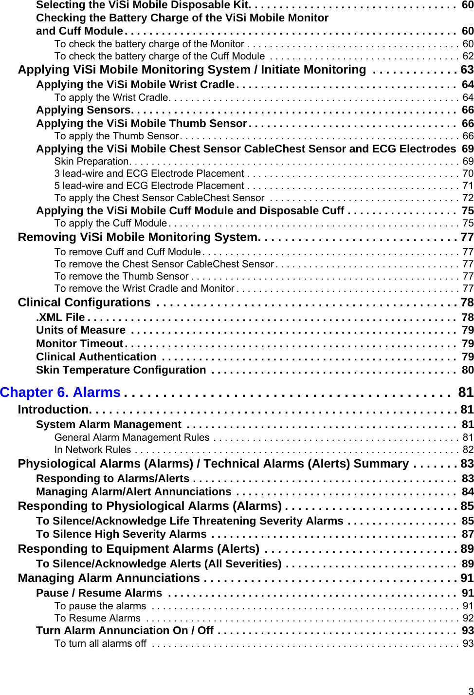
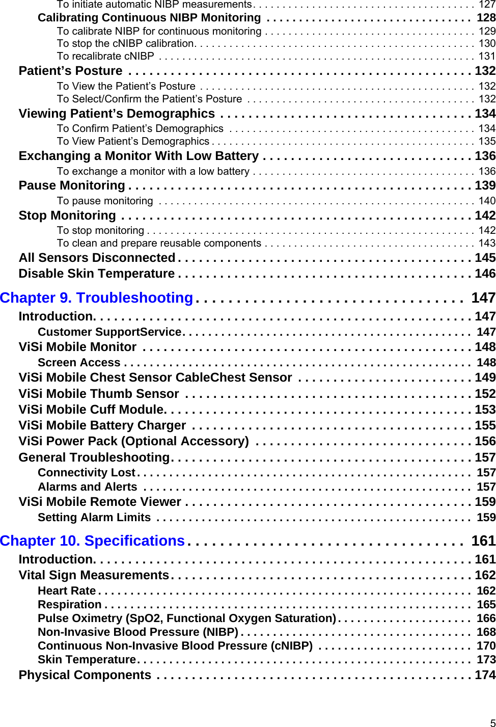


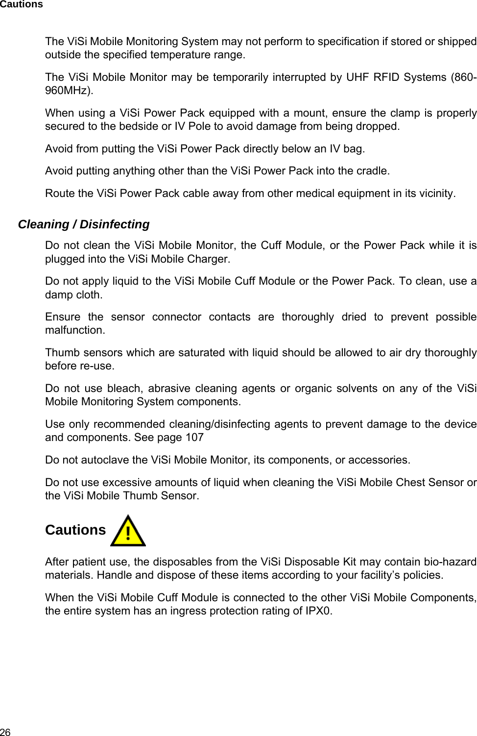


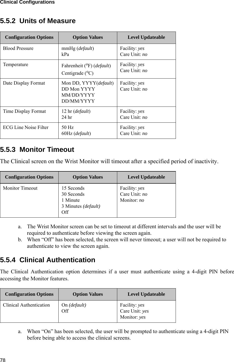
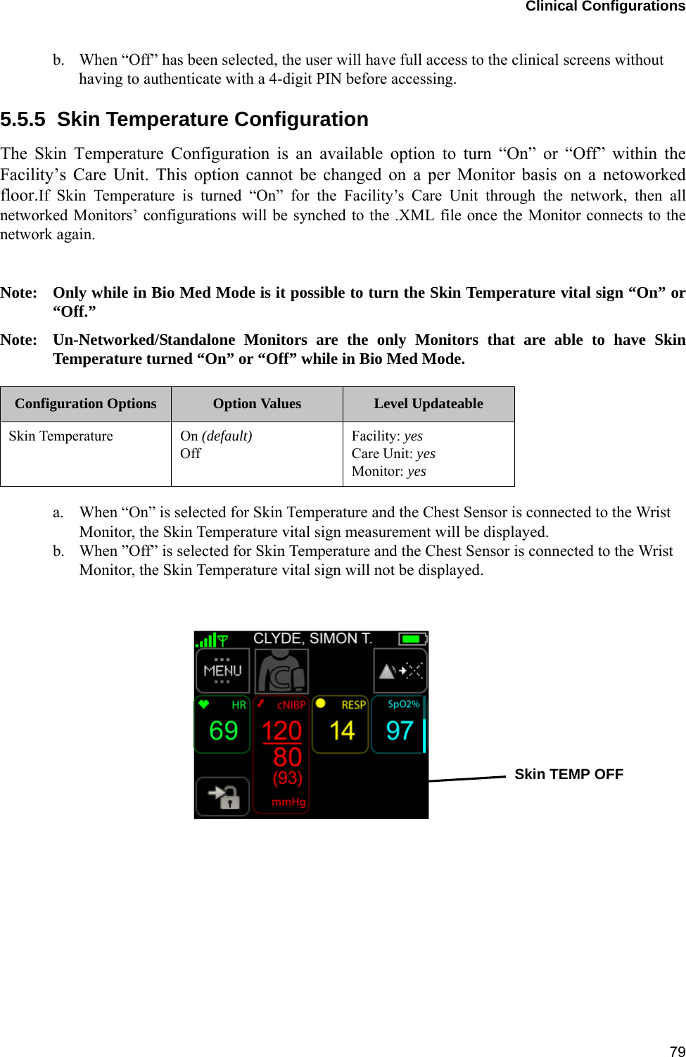

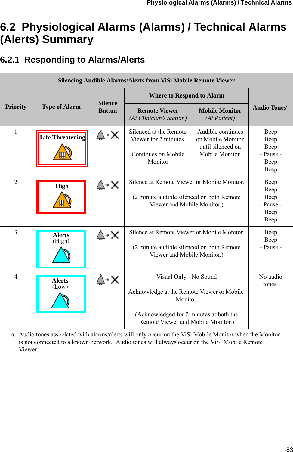
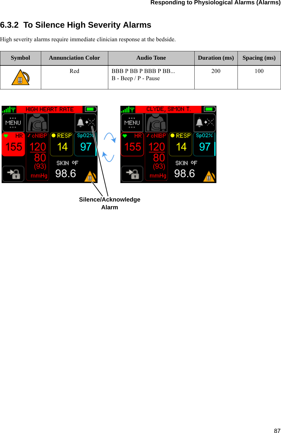

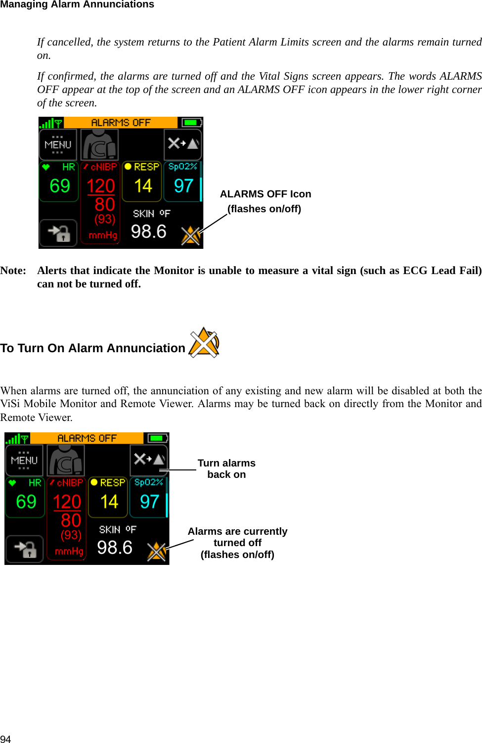


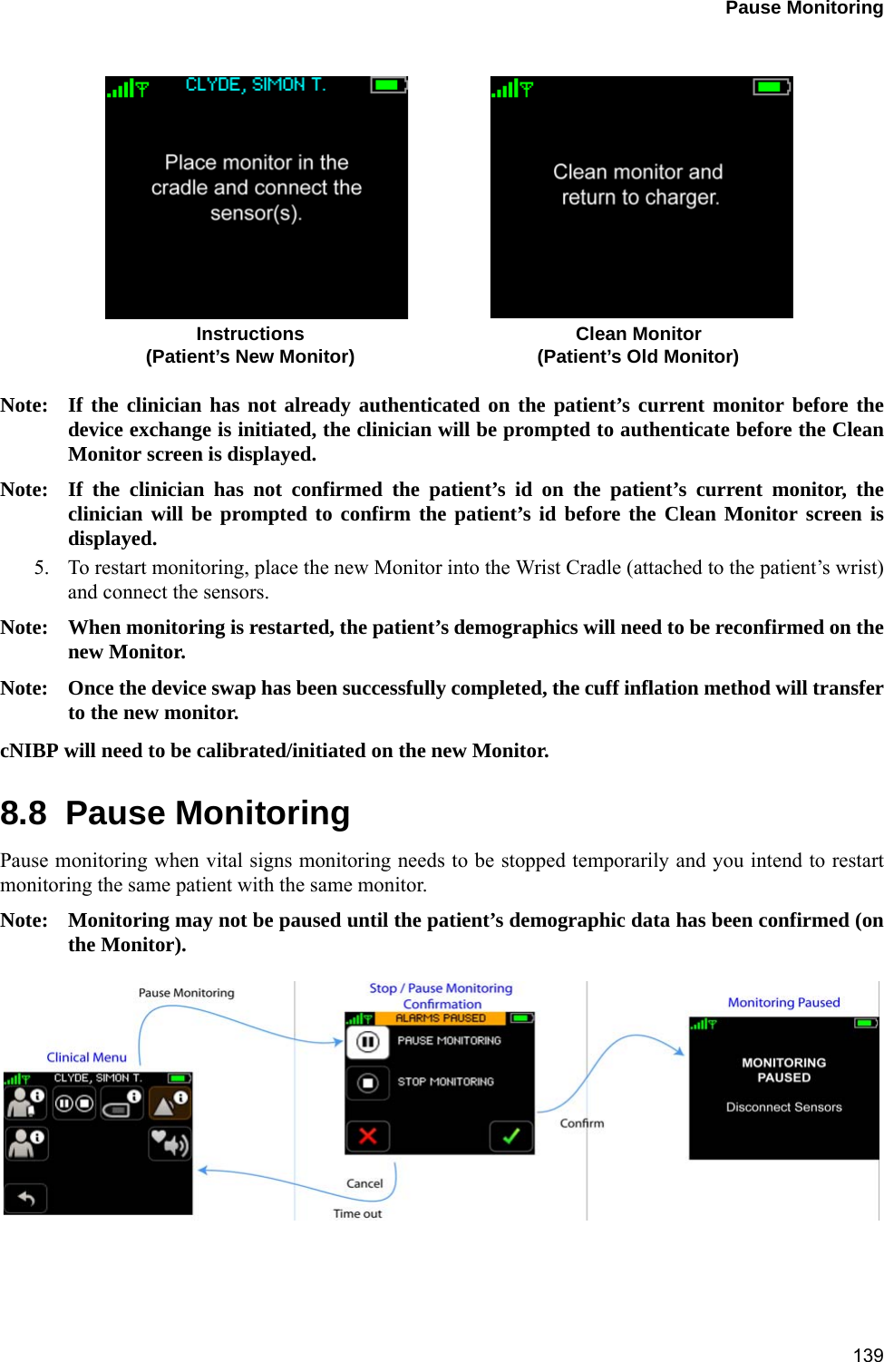

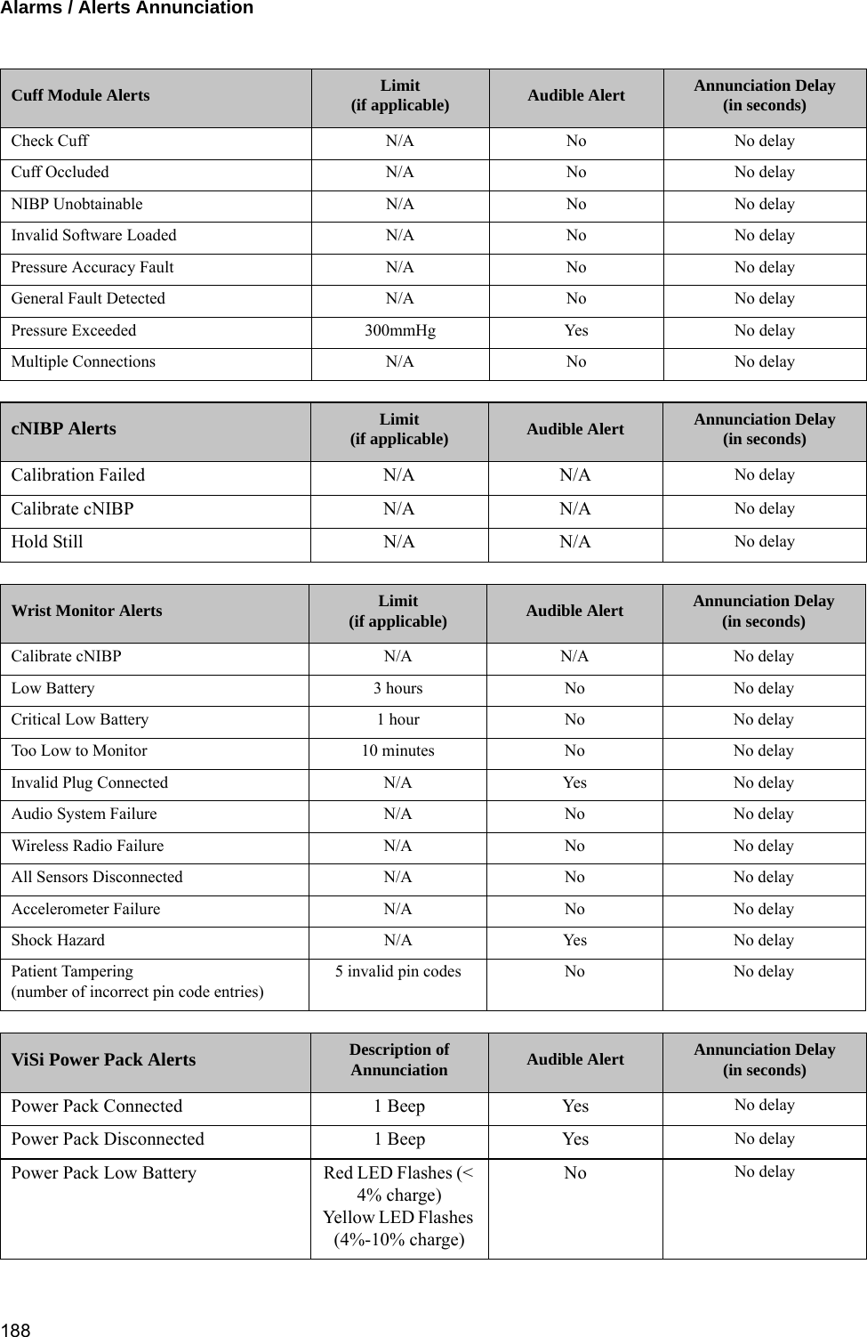
![Alarms / Alerts Annunciation 18410.4 Alarms / Alerts AnnunciationNote: An “Annunciation Delay” is the time that an alarm system deliberately delays the alarmannunciation (audibly and visually) to ensure clinical relevance of the detected alarmingcondition. Within the tables below, see column “Annunciation Delay” for the pre-definedperiods of time.10.4.1 Physiological Alarms (Alarms)Visual DisplayThe following table outlines the visual display when alarms are in progress:Audio TonesThe following table outlines the audio tones when alarms are in progress:Alarm Limits and Delays (factory default settings).Severity Indicator Attributes Toggle / Flash Speed Duty CycleHigh Priority Red 1.5 Hz 50% ONLife-Threatening Priority Red / White 1.5 Hz 50% ONSeverity Melodyaa. Melodies are defined as musical notes.Volume[dB]Frequency(fo) [Hz] Duration(td) [ms] Spacing(ts) [ms] 5th-6th[s] Inter-Burst(tb) [s]Life Threatening b5.b5.b5..b5.b5 78 987.767 100 50 0.35 2.5High b5.b5.b5..b5.b5 78 987.767 200 100 0.35 5Vital Sign Lower Limit Upper Limit Annunciation DelayaCare Unit Patient Patient Care Unit (seconds)Critical Low HR (BPM) 18 18 N/A N/A 5Heart Rate (BPM) 30 30 150 200 5Pulse Rate (BPM) 30 30 150 200 30BP Systolic (mmHg) 70 OFF 190 240 120BP Diastolic (mmHg) 40 OFF OFF 150 120BP MAP (mmHg) 60 65 OFF 170 90Respiration (BR/MIN) 4 4 35 40 120SpO2 (%) 85 85 N/A N/A 60Skin Temperature N/A N/A N/A N/A N/A](https://usermanual.wiki/Sotera-Wireless/VISI-MOBILE-1/User-Guide-2732946-Page-186.png)
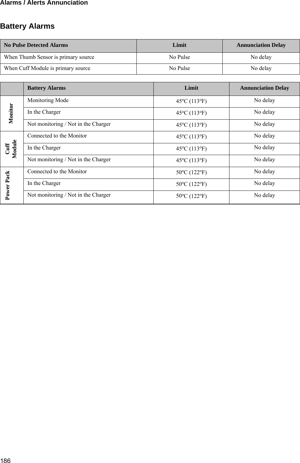
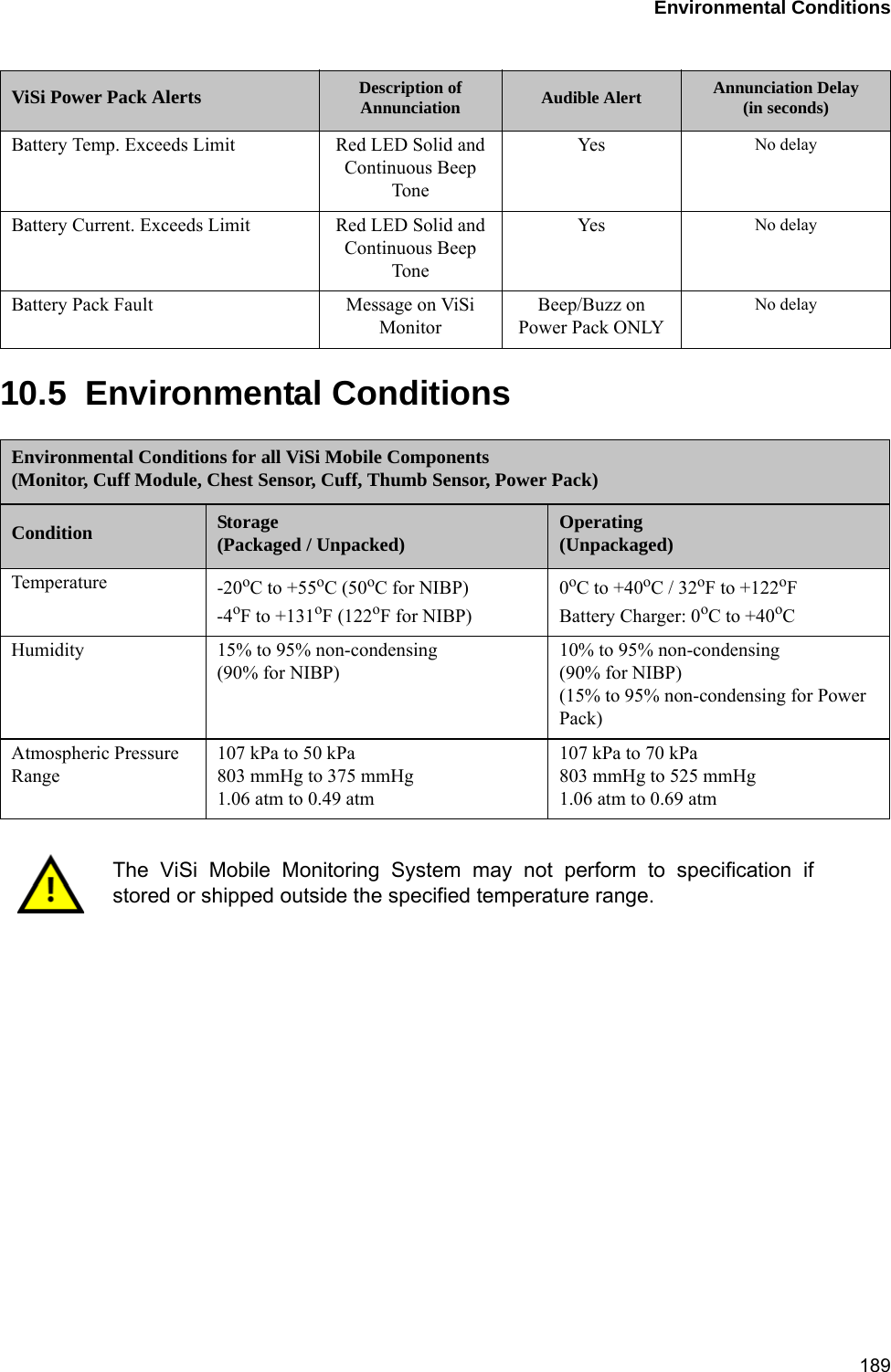
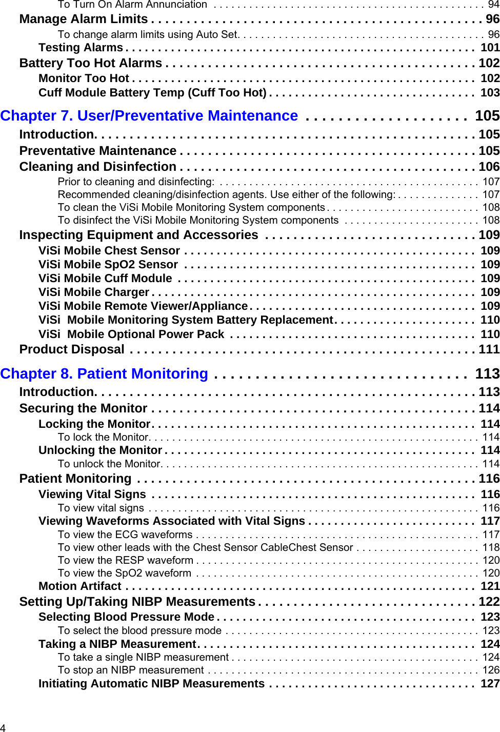
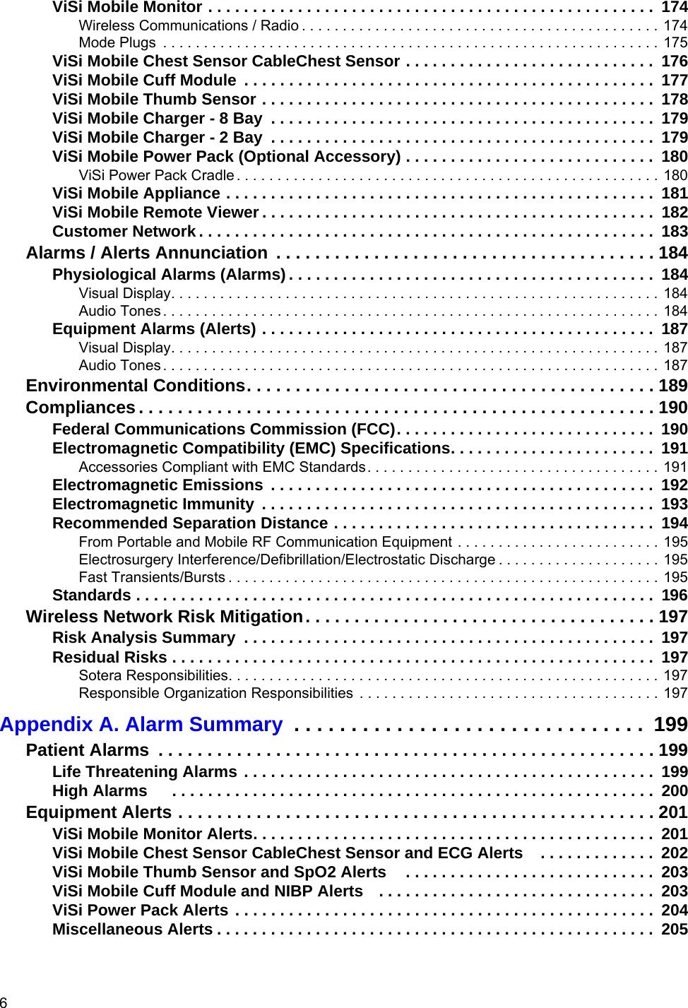
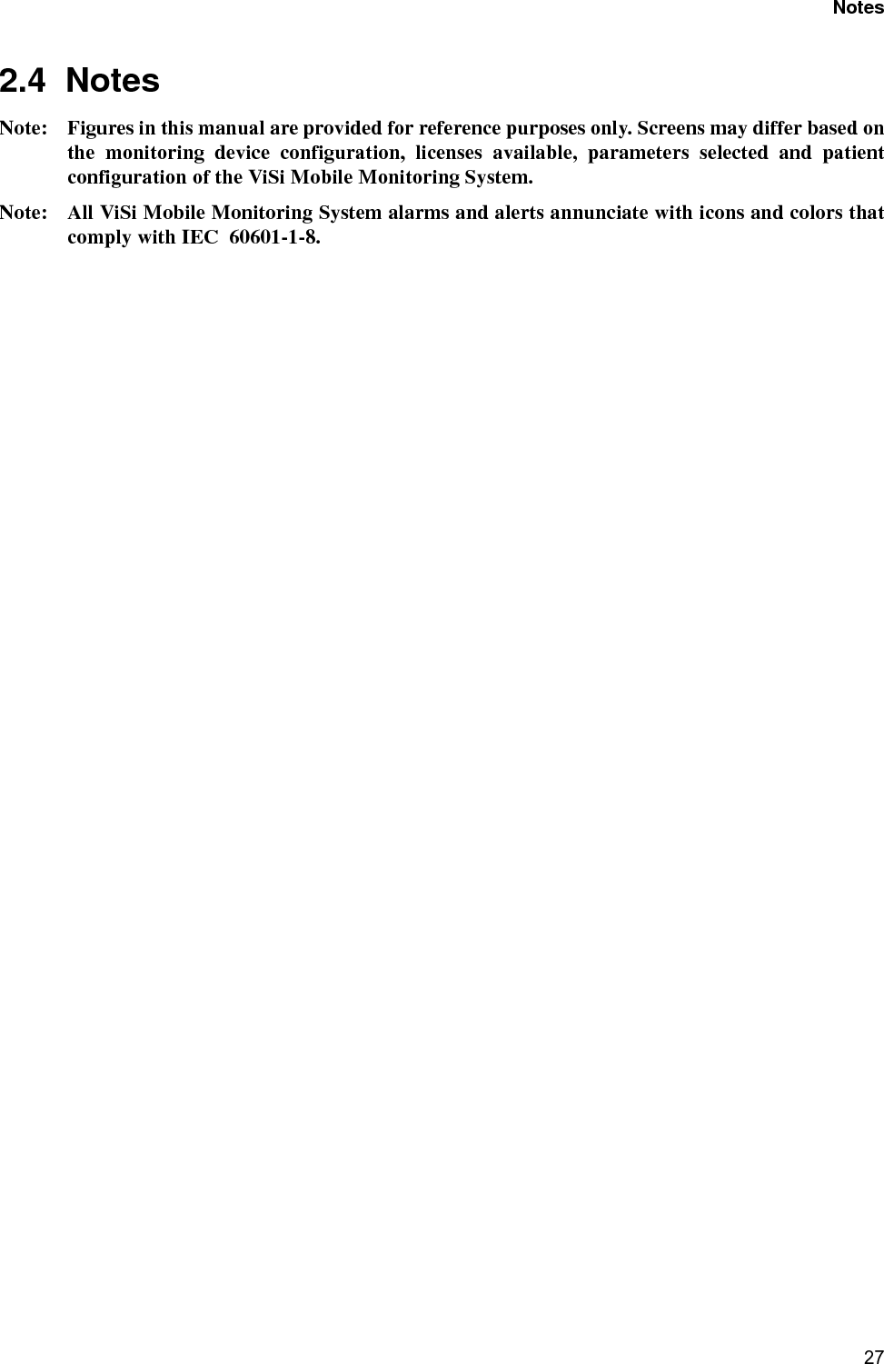
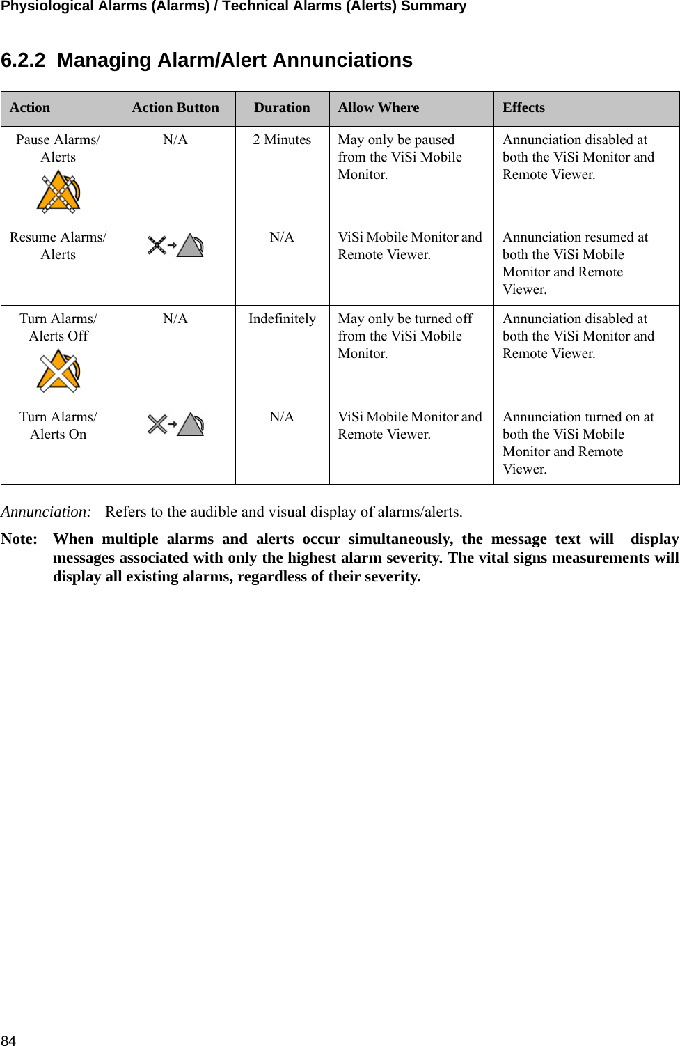
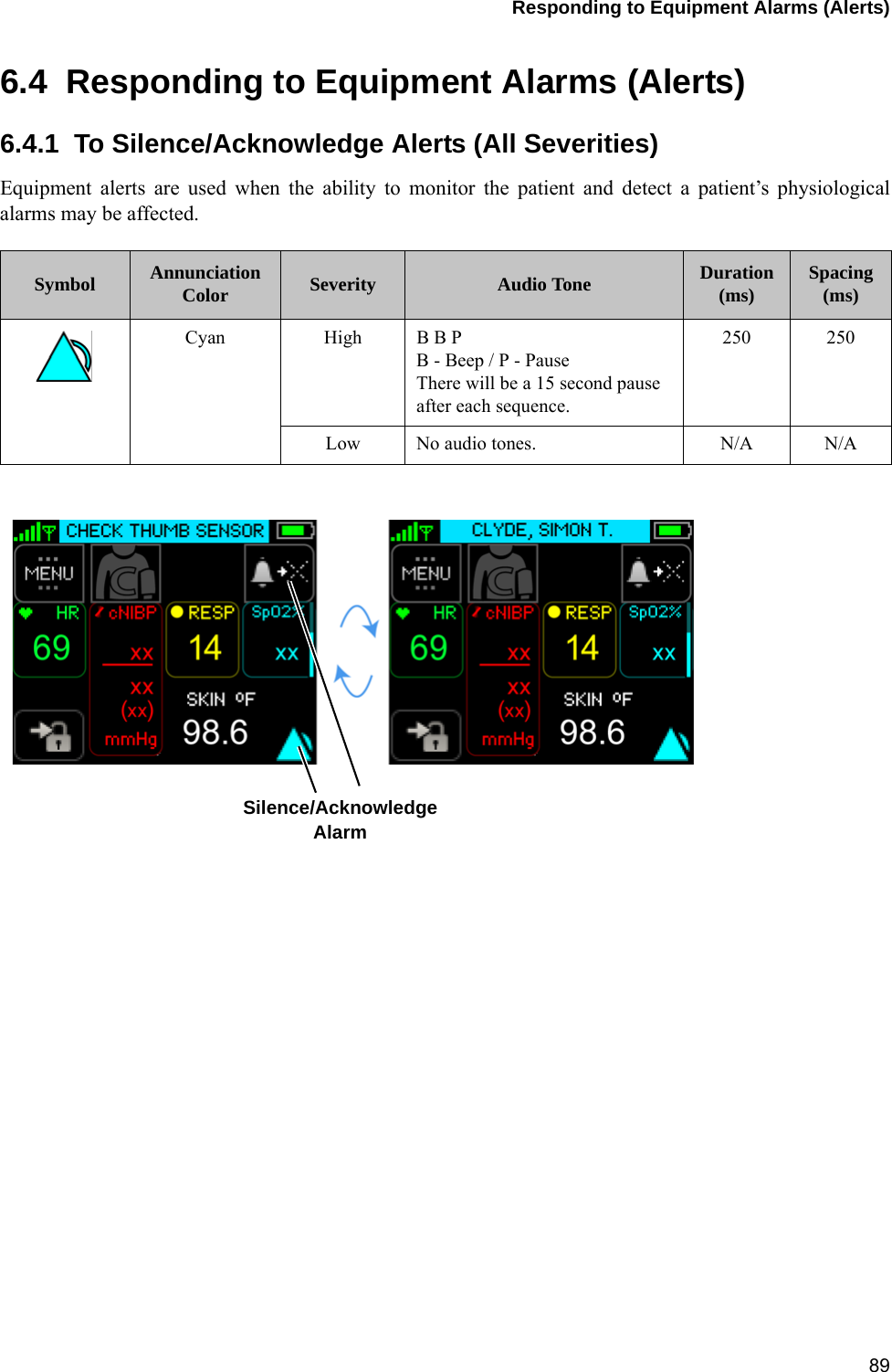
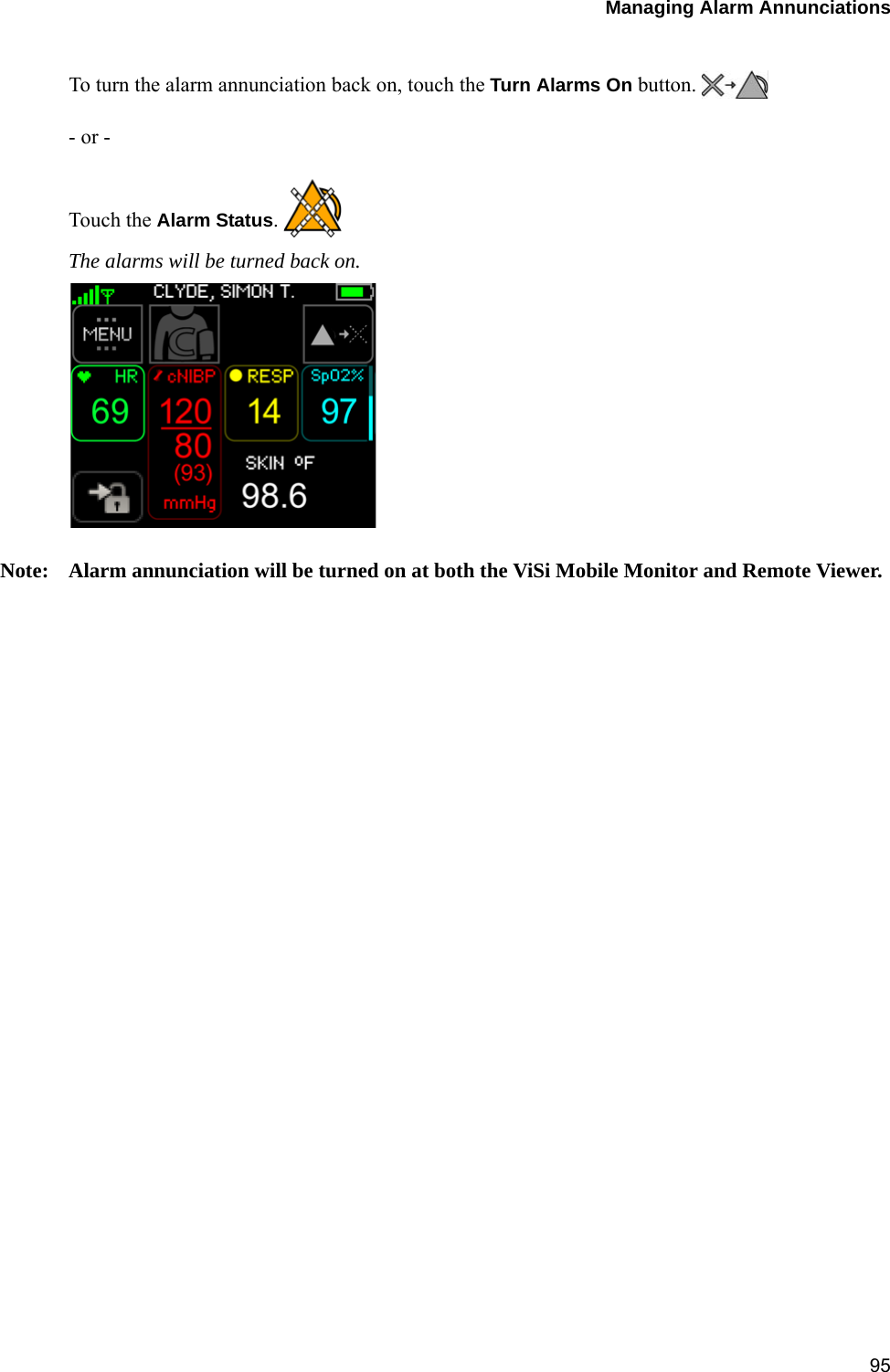
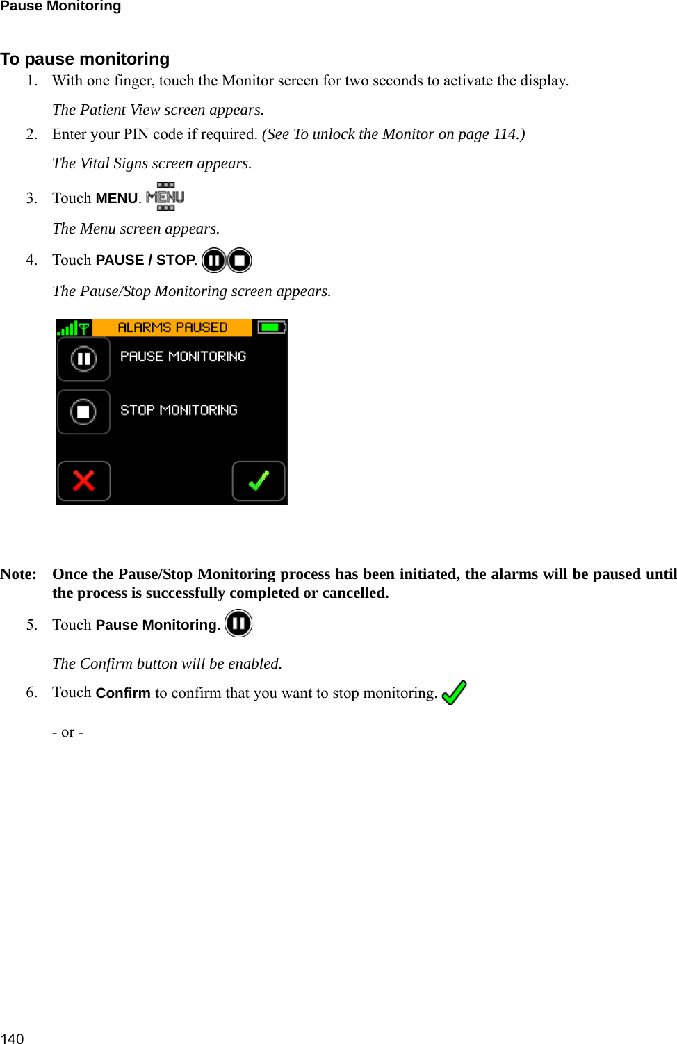
![Alarms / Alerts Annunciation18710.4.2 Equipment Alarms (Alerts)Visual DisplayThe following table outlines the visual display when alerts are in progress:Audio TonesThe following table outlines the audio tones when alerts are in progress:Note: There are no audio tones associated with low severity alerts.Alarm Limits and Delays (factory default settings)Severity Indicator Attributes Toggle / Flash Speed Duty CycleAll Severities Cyan (Blue) Constant (ON) 100% ONSeverity Melodyaa. Melodies are defined as musical notes.Volume[dB] Frequency(fo) [Hz] Duration(td) [ms] Spacing(ts) [ms] Inter-Burst(tb) [s]High e5.c5 68/63 659.255, 523.251 250 250 15Chest Sensor Alerts Limit(if applicable) Audible Alert Annunciation DelayECG Lead Failure N/A No No delayAll ECG Lead Failure N/A No No delayChest Sensor Disconnected N/A No No delayGeneral Fault Detected N/A No No delayMultiple Connections N/A No No delayTemperature Sensor Fault N/A No No delayAccelerometer Fault - Chest Module N/A No No delayAccelerometer Fault - Upper Arm N/A No No delayThumb Sensor Alerts Limit(if applicable) Audible Alert Annunciation Delay(in seconds)Thumb Sensor Off N/A No < 30Thumb Sensor Disconnected N/A No No delayCuff Module Alerts Limit(if applicable) Audible Alert Annunciation Delay(in seconds)Low Battery 4% to 10% No No delayBattery Empty < 4% No No delay](https://usermanual.wiki/Sotera-Wireless/VISI-MOBILE-1/User-Guide-2732946-Page-189.png)