Sotera Wireless VISI-MOBILE-1 92-10010 User Manual PWD IFU
Sotera Wireless, Inc. 92-10010 PWD IFU
User Manual

1
Monitoring System
User manual
July2015
Reference Number (USB): 95-10134
Reference Number (Hardcopy): 95-10060
Part Number: 6-000212-15
10020 Huennekens Street
San Diego, California 92121 USA
Phone: +1 (866) 232-6126 (U.S.)
+1 (858) 427-4620 (Intl)
Fax: +1 (858) 999-2487
Email: support@soterawireless.com
EMERGO EUROPE
Molenstraat 15, 2513BH
The Hague
The Netherlands
For additional information or assistance, please contact Sotera® Wireless, Inc. or an authorized Sotera
Wireless, Inc. representative in your area.
0297
2
Copyright
This publication is provided for informational purposes only and Sotera Wireless, Inc., makes no
warranties, either express or implied, in this document. Information in this document is subject to change
without notice. The entire risk of the use or the results of the use of this document remains with the user.
Unless otherwise noted, the example companies, organizations, products, domain names, e-mail addresses,
logos, people, places, and events depicted herein are fictitious, and no association with any real company,
organization, product, domain name, e-mail address, logo, person, place, or event is intended or should be
inferred. Complying with all applicable copyright laws is the responsibility of the user. Without limiting
the rights under copyright, no part of this document may be reproduced, stored in or introduced into a
retrieval system, or transmitted in any form or by any means (electronic, mechanical, photocopying,
recording, or otherwise), or for any purpose, without the express written permission of Sotera Wireless,
Inc.
Sotera Wireless, Inc., may have patents, patent applications, trademarks, copyrights, or other intellectual
property rights covering subject matter in this document. Except as expressly provided in any written
license agreement from Sotera Wireless, Inc., the furnishing of this document does not give you any
license to these patents, trademarks, copyrights, or other intellectual property.
For additional information or assistance, please contact Sotera Wireless, Inc. or an authorized Sotera
Wireless, Inc. representative in your area.
© 2015 Sotera Wireless, Inc. All rights reserved.
ViSi Mobile® Monitoring System is a trademark of Sotera® Wireless, Inc.

1
Contents
Chapter 1. Preface . . . . . . . . . . . . . . . . . . . . . . . . . . . . . . . . . . . . . . . . . 11
Introduction. . . . . . . . . . . . . . . . . . . . . . . . . . . . . . . . . . . . . . . . . . . . . . . . . . . . . . . 11
Intended Use. . . . . . . . . . . . . . . . . . . . . . . . . . . . . . . . . . . . . . . . . . . . . . . . . . . . . . 12
Contraindications. . . . . . . . . . . . . . . . . . . . . . . . . . . . . . . . . . . . . . . . . . . . . . . . . . . . . 12
Chapter 2. ViSi Mobile Warnings and Cautions. . . . . . . . . . . . . . . . . . 13
Introduction. . . . . . . . . . . . . . . . . . . . . . . . . . . . . . . . . . . . . . . . . . . . . . . . . . . . . . . 13
Warnings . . . . . . . . . . . . . . . . . . . . . . . . . . . . . . . . . . . . . . . . . . . . . . . . . . . . . . . . 14
Intended Use . . . . . . . . . . . . . . . . . . . . . . . . . . . . . . . . . . . . . . . . . . . . . . . . . . . . . . . . . . 14
Safety . . . . . . . . . . . . . . . . . . . . . . . . . . . . . . . . . . . . . . . . . . . . . . . . . . . . . . . . . . . . . . . 14
Disposable Components . . . . . . . . . . . . . . . . . . . . . . . . . . . . . . . . . . . . . . . . . . . . . . . . . 16
Patient Monitoring . . . . . . . . . . . . . . . . . . . . . . . . . . . . . . . . . . . . . . . . . . . . . . . . . . . . . . 16
Vital Signs . . . . . . . . . . . . . . . . . . . . . . . . . . . . . . . . . . . . . . . . . . . . . . . . . . . . . . . . . . . . 18
. . . . . . . . . . . . . . . . . . . . . . . . . . . . . . . . . . . . . . . . . . . . . . . . . . . . . . . . . . . . . . . . . . . . . 18
Chest Sensor CableChest Sensor: ECG, Respiration, Temperature (Skin). . . . . . . . . . 19
Cuff Module / NIBP . . . . . . . . . . . . . . . . . . . . . . . . . . . . . . . . . . . . . . . . . . . . . . . . . . . . . 20
SpO2 . . . . . . . . . . . . . . . . . . . . . . . . . . . . . . . . . . . . . . . . . . . . . . . . . . . . . . . . . . . . . . . . 20
Alarms / Alerts . . . . . . . . . . . . . . . . . . . . . . . . . . . . . . . . . . . . . . . . . . . . . . . . . . . . . . . . . 21
User Maintenance . . . . . . . . . . . . . . . . . . . . . . . . . . . . . . . . . . . . . . . . . . . . . . . . . . . . . . 22
Wireless Communications . . . . . . . . . . . . . . . . . . . . . . . . . . . . . . . . . . . . . . . . . . . . . . . . 22
Off-The-Shelf (OTS) Software . . . . . . . . . . . . . . . . . . . . . . . . . . . . . . . . . . . . . . . . . . . . . 22
Cautions . . . . . . . . . . . . . . . . . . . . . . . . . . . . . . . . . . . . . . . . . . . . . . . . . . . . . . . . . 23
Intended Use . . . . . . . . . . . . . . . . . . . . . . . . . . . . . . . . . . . . . . . . . . . . . . . . . . . . . . . . . . 23
General . . . . . . . . . . . . . . . . . . . . . . . . . . . . . . . . . . . . . . . . . . . . . . . . . . . . . . . . . . . . . . 23
Monitoring . . . . . . . . . . . . . . . . . . . . . . . . . . . . . . . . . . . . . . . . . . . . . . . . . . . . . . . . . . . . 23
Safety . . . . . . . . . . . . . . . . . . . . . . . . . . . . . . . . . . . . . . . . . . . . . . . . . . . . . . . . . . . . . . . 24
Service / Maintenance . . . . . . . . . . . . . . . . . . . . . . . . . . . . . . . . . . . . . . . . . . . . . . . . . . . 25
Equipment / Components . . . . . . . . . . . . . . . . . . . . . . . . . . . . . . . . . . . . . . . . . . . . . . . . 25
Cleaning / Disinfecting . . . . . . . . . . . . . . . . . . . . . . . . . . . . . . . . . . . . . . . . . . . . . . . . . . . 26
Notes . . . . . . . . . . . . . . . . . . . . . . . . . . . . . . . . . . . . . . . . . . . . . . . . . . . . . . . . . . . . 28
Chapter 3. General Description . . . . . . . . . . . . . . . . . . . . . . . . . . . . . . . 29
Introduction. . . . . . . . . . . . . . . . . . . . . . . . . . . . . . . . . . . . . . . . . . . . . . . . . . . . . . . 29
Unpacking . . . . . . . . . . . . . . . . . . . . . . . . . . . . . . . . . . . . . . . . . . . . . . . . . . . . . . . . 30
Removing and Inserting the Shipping Plug. . . . . . . . . . . . . . . . . . . . . . . . . . . . . . . . 30
To remove the Shipping Plug. . . . . . . . . . . . . . . . . . . . . . . . . . . . . . . . . . . . . . . . . . . . . . . . . 30
To insert the Shipping Plug . . . . . . . . . . . . . . . . . . . . . . . . . . . . . . . . . . . . . . . . . . . . . . . . . . 30
System Components . . . . . . . . . . . . . . . . . . . . . . . . . . . . . . . . . . . . . . . . . . . . . . . 31
2
ViSi Mobile Disposable Kit . . . . . . . . . . . . . . . . . . . . . . . . . . . . . . . . . . . . . . . . . . . . . 31
ViSi Mobile Disposable Cuff. . . . . . . . . . . . . . . . . . . . . . . . . . . . . . . . . . . . . . . . . . . . . . . . . . 32
ECG Electrodes . . . . . . . . . . . . . . . . . . . . . . . . . . . . . . . . . . . . . . . . . . . . . . . . . . . . . . . . . . . 33
ViSi Mobile Wrist Cradle . . . . . . . . . . . . . . . . . . . . . . . . . . . . . . . . . . . . . . . . . . . . . . . . . . . . 33
ViSi Mobile Thumb Wrap . . . . . . . . . . . . . . . . . . . . . . . . . . . . . . . . . . . . . . . . . . . . . . . . . . . . 34
ViSi Mobile CableChest Sensor Securements. . . . . . . . . . . . . . . . . . . . . . . . . . . . . . . . . . . . 35
ViSi Mobile Monitor . . . . . . . . . . . . . . . . . . . . . . . . . . . . . . . . . . . . . . . . . . . . . . . . . . . 35
ViSi Mobile Thumb Sensor (SpO2/PR). . . . . . . . . . . . . . . . . . . . . . . . . . . . . . . . . . . . 36
ViSi Mobile Cuff Module . . . . . . . . . . . . . . . . . . . . . . . . . . . . . . . . . . . . . . . . . . . . . . . 37
ViSi Mobile Chest Sensor CableChest Sensor . . . . . . . . . . . . . . . . . . . . . . . . . . . . . 38
ViSi Mobile Charger . . . . . . . . . . . . . . . . . . . . . . . . . . . . . . . . . . . . . . . . . . . . . . . . . . . 40
To set up the Charger . . . . . . . . . . . . . . . . . . . . . . . . . . . . . . . . . . . . . . . . . . . . . . . . . . . . . . 40
Charging the ViSi Mobile Monitor and Cuff Module . . . . . . . . . . . . . . . . . . . . . . . . . 40
The ViSi Mobile Charger provided by Sotera Wireless, Inc. is the required Charger
for both the Monitor and the Cuff Module as well as for the optional ViSi Power Pack.
The Charger is capable of charging up to eight of any combination of Monitors, Cuff
Modules and Power Packs. To charge either the Monitor or the Cuff Module place
the flat end into one of the slots with the front facing outwards. . . . . . . . . . . . . . . 40
To chargeCharging the a Monitor . . . . . . . . . . . . . . . . . . . . . . . . . . . . . . . . . . . . . . . . . . . . . 42
To chargeCharging the a Cuff Module . . . . . . . . . . . . . . . . . . . . . . . . . . . . . . . . . . . . . . . . . . 44
Charging the Optional ViSi Power Pack. . . . . . . . . . . . . . . . . . . . . . . . . . . . . . . . . . . . . . . . . 44
. . . . . . . . . . . . . . . . . . . . . . . . . . . . . . . . . . . . . . . . . . . . . . . . . . . . . . . . . . . . . . . . . . . . . . . . 44
. . . . . . . . . . . . . . . . . . . . . . . . . . . . . . . . . . . . . . . . . . . . . . . . . . . . . . . . . . . . . . . . . . . . . . . . 44
Chapter 4. Clinical Features. . . . . . . . . . . . . . . . . . . . . . . . . . . . . . . . . . 45
Introduction. . . . . . . . . . . . . . . . . . . . . . . . . . . . . . . . . . . . . . . . . . . . . . . . . . . . . . . 45
Key Features. . . . . . . . . . . . . . . . . . . . . . . . . . . . . . . . . . . . . . . . . . . . . . . . . . . . . . 47
Overview of Clinical Features . . . . . . . . . . . . . . . . . . . . . . . . . . . . . . . . . . . . . . . . 47
ECG Monitoring and Heart Rate (HR) Monitoring . . . . . . . . . . . . . . . . . . . . . . . . . . . 47
Respiration Rate (RESP) Monitoring . . . . . . . . . . . . . . . . . . . . . . . . . . . . . . . . . . . . . 47
Skin Temperature (TEMP) Monitoring . . . . . . . . . . . . . . . . . . . . . . . . . . . . . . . . . . . . 48
Pulse Oximetry (SpO2 and Pulse Rate) Monitoring . . . . . . . . . . . . . . . . . . . . . . . . . 48
NIBP Monitoring. . . . . . . . . . . . . . . . . . . . . . . . . . . . . . . . . . . . . . . . . . . . . . . . . . . . . . 49
Display Screens . . . . . . . . . . . . . . . . . . . . . . . . . . . . . . . . . . . . . . . . . . . . . . . . . . . 50
Battery Charge Screen . . . . . . . . . . . . . . . . . . . . . . . . . . . . . . . . . . . . . . . . . . . . . . . . 50
Hibernation Screen . . . . . . . . . . . . . . . . . . . . . . . . . . . . . . . . . . . . . . . . . . . . . . . . . . . 51
Vital Signs Screen . . . . . . . . . . . . . . . . . . . . . . . . . . . . . . . . . . . . . . . . . . . . . . . . . . . . 52
Menu Screen. . . . . . . . . . . . . . . . . . . . . . . . . . . . . . . . . . . . . . . . . . . . . . . . . . . . . . . . . 53
Monitor Status Screen. . . . . . . . . . . . . . . . . . . . . . . . . . . . . . . . . . . . . . . . . . . . . . . . . 54
Quiet Monitoring Screen . . . . . . . . . . . . . . . . . . . . . . . . . . . . . . . . . . . . . . . . . . . . . . . 54
Patient View Screen. . . . . . . . . . . . . . . . . . . . . . . . . . . . . . . . . . . . . . . . . . . . . . . . . . . 55
Chapter 5. Operation . . . . . . . . . . . . . . . . . . . . . . . . . . . . . . . . . . . . . . . 57
Introduction. . . . . . . . . . . . . . . . . . . . . . . . . . . . . . . . . . . . . . . . . . . . . . . . . . . . . . . 57
Preparing for a New Patient. . . . . . . . . . . . . . . . . . . . . . . . . . . . . . . . . . . . . . . . . . 57
Inspecting the Equipment and Accessories . . . . . . . . . . . . . . . . . . . . . . . . . . . . . . . 57
Applying Sensors. . . . . . . . . . . . . . . . . . . . . . . . . . . . . . . . . . . . . . . . . . . . . . . . . . . . . 58
Selecting Vital Signs to Monitor . . . . . . . . . . . . . . . . . . . . . . . . . . . . . . . . . . . . . . . . . 59
Selecting the ViSi Mobile Chest Sensor CableChest Sensor . . . . . . . . . . . . . . . . . 59
3
Selecting the ViSi Mobile Disposable Kit. . . . . . . . . . . . . . . . . . . . . . . . . . . . . . . . . . 60
Checking the Battery Charge of the ViSi Mobile Monitor
and Cuff Module. . . . . . . . . . . . . . . . . . . . . . . . . . . . . . . . . . . . . . . . . . . . . . . . . . . . . . 60
To check the battery charge of the Monitor . . . . . . . . . . . . . . . . . . . . . . . . . . . . . . . . . . . . . . 60
To check the battery charge of the Cuff Module . . . . . . . . . . . . . . . . . . . . . . . . . . . . . . . . . . 62
Applying ViSi Mobile Monitoring System / Initiate Monitoring . . . . . . . . . . . . . 63
Applying the ViSi Mobile Wrist Cradle. . . . . . . . . . . . . . . . . . . . . . . . . . . . . . . . . . . . 64
To apply the Wrist Cradle. . . . . . . . . . . . . . . . . . . . . . . . . . . . . . . . . . . . . . . . . . . . . . . . . . . . 64
Applying Sensors. . . . . . . . . . . . . . . . . . . . . . . . . . . . . . . . . . . . . . . . . . . . . . . . . . . . . 66
Applying the ViSi Mobile Thumb Sensor. . . . . . . . . . . . . . . . . . . . . . . . . . . . . . . . . . 66
To apply the Thumb Sensor. . . . . . . . . . . . . . . . . . . . . . . . . . . . . . . . . . . . . . . . . . . . . . . . . . 66
Applying the ViSi Mobile Chest Sensor CableChest Sensor and ECG Electrodes 69
Skin Preparation. . . . . . . . . . . . . . . . . . . . . . . . . . . . . . . . . . . . . . . . . . . . . . . . . . . . . . . . . . . 69
3 lead-wire and ECG Electrode Placement . . . . . . . . . . . . . . . . . . . . . . . . . . . . . . . . . . . . . . 70
5 lead-wire and ECG Electrode Placement . . . . . . . . . . . . . . . . . . . . . . . . . . . . . . . . . . . . . . 71
To apply the Chest Sensor CableChest Sensor . . . . . . . . . . . . . . . . . . . . . . . . . . . . . . . . . . 72
Applying the ViSi Mobile Cuff Module and Disposable Cuff . . . . . . . . . . . . . . . . . . 75
To apply the Cuff Module . . . . . . . . . . . . . . . . . . . . . . . . . . . . . . . . . . . . . . . . . . . . . . . . . . . . 75
Removing ViSi Mobile Monitoring System. . . . . . . . . . . . . . . . . . . . . . . . . . . . . . 77
To remove Cuff and Cuff Module . . . . . . . . . . . . . . . . . . . . . . . . . . . . . . . . . . . . . . . . . . . . . . 77
To remove the Chest Sensor CableChest Sensor . . . . . . . . . . . . . . . . . . . . . . . . . . . . . . . . . 77
To remove the Thumb Sensor . . . . . . . . . . . . . . . . . . . . . . . . . . . . . . . . . . . . . . . . . . . . . . . . 77
To remove the Wrist Cradle and Monitor . . . . . . . . . . . . . . . . . . . . . . . . . . . . . . . . . . . . . . . . 77
Clinical Configurations . . . . . . . . . . . . . . . . . . . . . . . . . . . . . . . . . . . . . . . . . . . . . 78
.XML File . . . . . . . . . . . . . . . . . . . . . . . . . . . . . . . . . . . . . . . . . . . . . . . . . . . . . . . . . . . . 78
Units of Measure . . . . . . . . . . . . . . . . . . . . . . . . . . . . . . . . . . . . . . . . . . . . . . . . . . . . . 79
Monitor Timeout. . . . . . . . . . . . . . . . . . . . . . . . . . . . . . . . . . . . . . . . . . . . . . . . . . . . . . 79
Clinical Authentication . . . . . . . . . . . . . . . . . . . . . . . . . . . . . . . . . . . . . . . . . . . . . . . . 79
Skin Temperature Configuration . . . . . . . . . . . . . . . . . . . . . . . . . . . . . . . . . . . . . . . . 80
Chapter 6. Alarms . . . . . . . . . . . . . . . . . . . . . . . . . . . . . . . . . . . . . . . . . . 81
Introduction. . . . . . . . . . . . . . . . . . . . . . . . . . . . . . . . . . . . . . . . . . . . . . . . . . . . . . . 81
System Alarm Management . . . . . . . . . . . . . . . . . . . . . . . . . . . . . . . . . . . . . . . . . . . . 81
General Alarm Management Rules . . . . . . . . . . . . . . . . . . . . . . . . . . . . . . . . . . . . . . . . . . . . 81
In Network Rules . . . . . . . . . . . . . . . . . . . . . . . . . . . . . . . . . . . . . . . . . . . . . . . . . . . . . . . . . . 82
Physiological Alarms (Alarms) / Technical Alarms (Alerts) Summary . . . . . . . 83
Responding to Alarms/Alerts . . . . . . . . . . . . . . . . . . . . . . . . . . . . . . . . . . . . . . . . . . . 83
Managing Alarm/Alert Annunciations . . . . . . . . . . . . . . . . . . . . . . . . . . . . . . . . . . . . 84
Responding to Physiological Alarms (Alarms) . . . . . . . . . . . . . . . . . . . . . . . . . . 85
To Silence/Acknowledge Life Threatening Severity Alarms . . . . . . . . . . . . . . . . . . 85
To Silence High Severity Alarms . . . . . . . . . . . . . . . . . . . . . . . . . . . . . . . . . . . . . . . . 87
Responding to Equipment Alarms (Alerts) . . . . . . . . . . . . . . . . . . . . . . . . . . . . . 89
To Silence/Acknowledge Alerts (All Severities) . . . . . . . . . . . . . . . . . . . . . . . . . . . . 89
Managing Alarm Annunciations . . . . . . . . . . . . . . . . . . . . . . . . . . . . . . . . . . . . . . 91
Pause / Resume Alarms . . . . . . . . . . . . . . . . . . . . . . . . . . . . . . . . . . . . . . . . . . . . . . . 91
To pause the alarms . . . . . . . . . . . . . . . . . . . . . . . . . . . . . . . . . . . . . . . . . . . . . . . . . . . . . . . 91
To Resume Alarms . . . . . . . . . . . . . . . . . . . . . . . . . . . . . . . . . . . . . . . . . . . . . . . . . . . . . . . . 92
Turn Alarm Annunciation On / Off . . . . . . . . . . . . . . . . . . . . . . . . . . . . . . . . . . . . . . . 93
To turn all alarms off . . . . . . . . . . . . . . . . . . . . . . . . . . . . . . . . . . . . . . . . . . . . . . . . . . . . . . . 93
4
To Turn On Alarm Annunciation . . . . . . . . . . . . . . . . . . . . . . . . . . . . . . . . . . . . . . . . . . . . . . 94
Manage Alarm Limits . . . . . . . . . . . . . . . . . . . . . . . . . . . . . . . . . . . . . . . . . . . . . . . 96
To change alarm limits using Auto Set. . . . . . . . . . . . . . . . . . . . . . . . . . . . . . . . . . . . . . . . . . 96
Testing Alarms . . . . . . . . . . . . . . . . . . . . . . . . . . . . . . . . . . . . . . . . . . . . . . . . . . . . . . 101
Battery Too Hot Alarms . . . . . . . . . . . . . . . . . . . . . . . . . . . . . . . . . . . . . . . . . . . . 102
Monitor Too Hot . . . . . . . . . . . . . . . . . . . . . . . . . . . . . . . . . . . . . . . . . . . . . . . . . . . . . 102
Cuff Module Battery Temp (Cuff Too Hot) . . . . . . . . . . . . . . . . . . . . . . . . . . . . . . . . 103
Chapter 7. User/Preventative Maintenance . . . . . . . . . . . . . . . . . . . . 105
Introduction. . . . . . . . . . . . . . . . . . . . . . . . . . . . . . . . . . . . . . . . . . . . . . . . . . . . . . 105
Preventative Maintenance . . . . . . . . . . . . . . . . . . . . . . . . . . . . . . . . . . . . . . . . . . 105
Cleaning and Disinfection . . . . . . . . . . . . . . . . . . . . . . . . . . . . . . . . . . . . . . . . . . 106
Prior to cleaning and disinfecting: . . . . . . . . . . . . . . . . . . . . . . . . . . . . . . . . . . . . . . . . . . . . 107
Recommended cleaning/disinfection agents. Use either of the following: . . . . . . . . . . . . . . 107
To clean the ViSi Mobile Monitoring System components . . . . . . . . . . . . . . . . . . . . . . . . . . 108
To disinfect the ViSi Mobile Monitoring System components . . . . . . . . . . . . . . . . . . . . . . . 108
Inspecting Equipment and Accessories . . . . . . . . . . . . . . . . . . . . . . . . . . . . . . 109
ViSi Mobile Chest Sensor . . . . . . . . . . . . . . . . . . . . . . . . . . . . . . . . . . . . . . . . . . . . . 109
ViSi Mobile SpO2 Sensor . . . . . . . . . . . . . . . . . . . . . . . . . . . . . . . . . . . . . . . . . . . . . 109
ViSi Mobile Cuff Module . . . . . . . . . . . . . . . . . . . . . . . . . . . . . . . . . . . . . . . . . . . . . . 109
ViSi Mobile Charger . . . . . . . . . . . . . . . . . . . . . . . . . . . . . . . . . . . . . . . . . . . . . . . . . . 109
ViSi Mobile Remote Viewer/Appliance. . . . . . . . . . . . . . . . . . . . . . . . . . . . . . . . . . . 109
ViSi Mobile Monitoring System Battery Replacement. . . . . . . . . . . . . . . . . . . . . . 110
ViSi Mobile Optional Power Pack . . . . . . . . . . . . . . . . . . . . . . . . . . . . . . . . . . . . . . 110
Product Disposal . . . . . . . . . . . . . . . . . . . . . . . . . . . . . . . . . . . . . . . . . . . . . . . . . 111
Chapter 8. Patient Monitoring . . . . . . . . . . . . . . . . . . . . . . . . . . . . . . . 113
Introduction. . . . . . . . . . . . . . . . . . . . . . . . . . . . . . . . . . . . . . . . . . . . . . . . . . . . . . 113
Securing the Monitor . . . . . . . . . . . . . . . . . . . . . . . . . . . . . . . . . . . . . . . . . . . . . . 114
Locking the Monitor. . . . . . . . . . . . . . . . . . . . . . . . . . . . . . . . . . . . . . . . . . . . . . . . . . 114
To lock the Monitor. . . . . . . . . . . . . . . . . . . . . . . . . . . . . . . . . . . . . . . . . . . . . . . . . . . . . . . . 114
Unlocking the Monitor . . . . . . . . . . . . . . . . . . . . . . . . . . . . . . . . . . . . . . . . . . . . . . . . 114
To unlock the Monitor. . . . . . . . . . . . . . . . . . . . . . . . . . . . . . . . . . . . . . . . . . . . . . . . . . . . . . 114
Patient Monitoring . . . . . . . . . . . . . . . . . . . . . . . . . . . . . . . . . . . . . . . . . . . . . . . . 116
Viewing Vital Signs . . . . . . . . . . . . . . . . . . . . . . . . . . . . . . . . . . . . . . . . . . . . . . . . . . 116
To view vital signs . . . . . . . . . . . . . . . . . . . . . . . . . . . . . . . . . . . . . . . . . . . . . . . . . . . . . . . . 116
Viewing Waveforms Associated with Vital Signs . . . . . . . . . . . . . . . . . . . . . . . . . . 117
To view the ECG waveforms . . . . . . . . . . . . . . . . . . . . . . . . . . . . . . . . . . . . . . . . . . . . . . . . 117
To view other leads with the Chest Sensor CableChest Sensor . . . . . . . . . . . . . . . . . . . . . 118
To view the RESP waveform . . . . . . . . . . . . . . . . . . . . . . . . . . . . . . . . . . . . . . . . . . . . . . . . 120
To view the SpO2 waveform . . . . . . . . . . . . . . . . . . . . . . . . . . . . . . . . . . . . . . . . . . . . . . . . 120
Motion Artifact . . . . . . . . . . . . . . . . . . . . . . . . . . . . . . . . . . . . . . . . . . . . . . . . . . . . . . 121
Setting Up/Taking NIBP Measurements . . . . . . . . . . . . . . . . . . . . . . . . . . . . . . . 122
Selecting Blood Pressure Mode . . . . . . . . . . . . . . . . . . . . . . . . . . . . . . . . . . . . . . . . 123
To select the blood pressure mode . . . . . . . . . . . . . . . . . . . . . . . . . . . . . . . . . . . . . . . . . . . 123
Taking a NIBP Measurement. . . . . . . . . . . . . . . . . . . . . . . . . . . . . . . . . . . . . . . . . . . 124
To take a single NIBP measurement . . . . . . . . . . . . . . . . . . . . . . . . . . . . . . . . . . . . . . . . . . 124
To stop an NIBP measurement . . . . . . . . . . . . . . . . . . . . . . . . . . . . . . . . . . . . . . . . . . . . . . 126
Initiating Automatic NIBP Measurements . . . . . . . . . . . . . . . . . . . . . . . . . . . . . . . . 127
5
To initiate automatic NIBP measurements. . . . . . . . . . . . . . . . . . . . . . . . . . . . . . . . . . . . . . 127
Calibrating Continuous NIBP Monitoring . . . . . . . . . . . . . . . . . . . . . . . . . . . . . . . . 128
To calibrate NIBP for continuous monitoring . . . . . . . . . . . . . . . . . . . . . . . . . . . . . . . . . . . . 129
To stop the cNIBP calibration. . . . . . . . . . . . . . . . . . . . . . . . . . . . . . . . . . . . . . . . . . . . . . . . 130
To recalibrate cNIBP . . . . . . . . . . . . . . . . . . . . . . . . . . . . . . . . . . . . . . . . . . . . . . . . . . . . . . 131
Patient’s Posture . . . . . . . . . . . . . . . . . . . . . . . . . . . . . . . . . . . . . . . . . . . . . . . . . 132
To View the Patient’s Posture . . . . . . . . . . . . . . . . . . . . . . . . . . . . . . . . . . . . . . . . . . . . . . . 132
To Select/Confirm the Patient’s Posture . . . . . . . . . . . . . . . . . . . . . . . . . . . . . . . . . . . . . . . 132
Viewing Patient’s Demographics . . . . . . . . . . . . . . . . . . . . . . . . . . . . . . . . . . . . 134
To Confirm Patient’s Demographics . . . . . . . . . . . . . . . . . . . . . . . . . . . . . . . . . . . . . . . . . . 134
To View Patient’s Demographics . . . . . . . . . . . . . . . . . . . . . . . . . . . . . . . . . . . . . . . . . . . . . 135
Exchanging a Monitor With Low Battery . . . . . . . . . . . . . . . . . . . . . . . . . . . . . . 136
To exchange a monitor with a low battery . . . . . . . . . . . . . . . . . . . . . . . . . . . . . . . . . . . . . . 136
Pause Monitoring . . . . . . . . . . . . . . . . . . . . . . . . . . . . . . . . . . . . . . . . . . . . . . . . . 139
To pause monitoring . . . . . . . . . . . . . . . . . . . . . . . . . . . . . . . . . . . . . . . . . . . . . . . . . . . . . . 140
Stop Monitoring . . . . . . . . . . . . . . . . . . . . . . . . . . . . . . . . . . . . . . . . . . . . . . . . . . 142
To stop monitoring . . . . . . . . . . . . . . . . . . . . . . . . . . . . . . . . . . . . . . . . . . . . . . . . . . . . . . . . 142
To clean and prepare reusable components . . . . . . . . . . . . . . . . . . . . . . . . . . . . . . . . . . . . 143
All Sensors Disconnected . . . . . . . . . . . . . . . . . . . . . . . . . . . . . . . . . . . . . . . . . . 145
Disable Skin Temperature . . . . . . . . . . . . . . . . . . . . . . . . . . . . . . . . . . . . . . . . . . 146
Chapter 9. Troubleshooting. . . . . . . . . . . . . . . . . . . . . . . . . . . . . . . . . 147
Introduction. . . . . . . . . . . . . . . . . . . . . . . . . . . . . . . . . . . . . . . . . . . . . . . . . . . . . . 147
Customer SupportService. . . . . . . . . . . . . . . . . . . . . . . . . . . . . . . . . . . . . . . . . . . . . 147
ViSi Mobile Monitor . . . . . . . . . . . . . . . . . . . . . . . . . . . . . . . . . . . . . . . . . . . . . . . 148
Screen Access . . . . . . . . . . . . . . . . . . . . . . . . . . . . . . . . . . . . . . . . . . . . . . . . . . . . . . 148
ViSi Mobile Chest Sensor CableChest Sensor . . . . . . . . . . . . . . . . . . . . . . . . . 149
ViSi Mobile Thumb Sensor . . . . . . . . . . . . . . . . . . . . . . . . . . . . . . . . . . . . . . . . . 152
ViSi Mobile Cuff Module. . . . . . . . . . . . . . . . . . . . . . . . . . . . . . . . . . . . . . . . . . . . 153
ViSi Mobile Battery Charger . . . . . . . . . . . . . . . . . . . . . . . . . . . . . . . . . . . . . . . . 155
ViSi Power Pack (Optional Accessory) . . . . . . . . . . . . . . . . . . . . . . . . . . . . . . . 156
General Troubleshooting. . . . . . . . . . . . . . . . . . . . . . . . . . . . . . . . . . . . . . . . . . . 157
Connectivity Lost. . . . . . . . . . . . . . . . . . . . . . . . . . . . . . . . . . . . . . . . . . . . . . . . . . . . 157
Alarms and Alerts . . . . . . . . . . . . . . . . . . . . . . . . . . . . . . . . . . . . . . . . . . . . . . . . . . . 157
ViSi Mobile Remote Viewer . . . . . . . . . . . . . . . . . . . . . . . . . . . . . . . . . . . . . . . . . 159
Setting Alarm Limits . . . . . . . . . . . . . . . . . . . . . . . . . . . . . . . . . . . . . . . . . . . . . . . . . 159
Chapter 10. Specifications. . . . . . . . . . . . . . . . . . . . . . . . . . . . . . . . . . 161
Introduction. . . . . . . . . . . . . . . . . . . . . . . . . . . . . . . . . . . . . . . . . . . . . . . . . . . . . . 161
Vital Sign Measurements. . . . . . . . . . . . . . . . . . . . . . . . . . . . . . . . . . . . . . . . . . . 162
Heart Rate . . . . . . . . . . . . . . . . . . . . . . . . . . . . . . . . . . . . . . . . . . . . . . . . . . . . . . . . . . 162
Respiration . . . . . . . . . . . . . . . . . . . . . . . . . . . . . . . . . . . . . . . . . . . . . . . . . . . . . . . . . 165
Pulse Oximetry (SpO2, Functional Oxygen Saturation). . . . . . . . . . . . . . . . . . . . . 166
Non-Invasive Blood Pressure (NIBP) . . . . . . . . . . . . . . . . . . . . . . . . . . . . . . . . . . . . 168
Continuous Non-Invasive Blood Pressure (cNIBP) . . . . . . . . . . . . . . . . . . . . . . . . 170
Skin Temperature. . . . . . . . . . . . . . . . . . . . . . . . . . . . . . . . . . . . . . . . . . . . . . . . . . . . 173
Physical Components . . . . . . . . . . . . . . . . . . . . . . . . . . . . . . . . . . . . . . . . . . . . . 174
6
ViSi Mobile Monitor . . . . . . . . . . . . . . . . . . . . . . . . . . . . . . . . . . . . . . . . . . . . . . . . . . 174
Wireless Communications / Radio . . . . . . . . . . . . . . . . . . . . . . . . . . . . . . . . . . . . . . . . . . . . 174
Mode Plugs . . . . . . . . . . . . . . . . . . . . . . . . . . . . . . . . . . . . . . . . . . . . . . . . . . . . . . . . . . . . . 175
ViSi Mobile Chest Sensor CableChest Sensor . . . . . . . . . . . . . . . . . . . . . . . . . . . . 176
ViSi Mobile Cuff Module . . . . . . . . . . . . . . . . . . . . . . . . . . . . . . . . . . . . . . . . . . . . . . 177
ViSi Mobile Thumb Sensor . . . . . . . . . . . . . . . . . . . . . . . . . . . . . . . . . . . . . . . . . . . . 178
ViSi Mobile Charger - 8 Bay . . . . . . . . . . . . . . . . . . . . . . . . . . . . . . . . . . . . . . . . . . . 179
ViSi Mobile Charger - 2 Bay . . . . . . . . . . . . . . . . . . . . . . . . . . . . . . . . . . . . . . . . . . . 179
ViSi Mobile Power Pack (Optional Accessory) . . . . . . . . . . . . . . . . . . . . . . . . . . . . 180
ViSi Power Pack Cradle . . . . . . . . . . . . . . . . . . . . . . . . . . . . . . . . . . . . . . . . . . . . . . . . . . . . 180
ViSi Mobile Appliance . . . . . . . . . . . . . . . . . . . . . . . . . . . . . . . . . . . . . . . . . . . . . . . . 181
ViSi Mobile Remote Viewer . . . . . . . . . . . . . . . . . . . . . . . . . . . . . . . . . . . . . . . . . . . . 182
Customer Network . . . . . . . . . . . . . . . . . . . . . . . . . . . . . . . . . . . . . . . . . . . . . . . . . . . 183
Alarms / Alerts Annunciation . . . . . . . . . . . . . . . . . . . . . . . . . . . . . . . . . . . . . . . 184
Physiological Alarms (Alarms) . . . . . . . . . . . . . . . . . . . . . . . . . . . . . . . . . . . . . . . . . 184
Visual Display. . . . . . . . . . . . . . . . . . . . . . . . . . . . . . . . . . . . . . . . . . . . . . . . . . . . . . . . . . . . 184
Audio Tones . . . . . . . . . . . . . . . . . . . . . . . . . . . . . . . . . . . . . . . . . . . . . . . . . . . . . . . . . . . . . 184
Equipment Alarms (Alerts) . . . . . . . . . . . . . . . . . . . . . . . . . . . . . . . . . . . . . . . . . . . . 187
Visual Display. . . . . . . . . . . . . . . . . . . . . . . . . . . . . . . . . . . . . . . . . . . . . . . . . . . . . . . . . . . . 187
Audio Tones . . . . . . . . . . . . . . . . . . . . . . . . . . . . . . . . . . . . . . . . . . . . . . . . . . . . . . . . . . . . . 187
Environmental Conditions. . . . . . . . . . . . . . . . . . . . . . . . . . . . . . . . . . . . . . . . . . 189
Compliances . . . . . . . . . . . . . . . . . . . . . . . . . . . . . . . . . . . . . . . . . . . . . . . . . . . . . 190
Federal Communications Commission (FCC). . . . . . . . . . . . . . . . . . . . . . . . . . . . . 190
Electromagnetic Compatibility (EMC) Specifications. . . . . . . . . . . . . . . . . . . . . . . 191
Accessories Compliant with EMC Standards. . . . . . . . . . . . . . . . . . . . . . . . . . . . . . . . . . . . 191
Electromagnetic Emissions . . . . . . . . . . . . . . . . . . . . . . . . . . . . . . . . . . . . . . . . . . . 192
Electromagnetic Immunity . . . . . . . . . . . . . . . . . . . . . . . . . . . . . . . . . . . . . . . . . . . . 193
Recommended Separation Distance . . . . . . . . . . . . . . . . . . . . . . . . . . . . . . . . . . . . 194
From Portable and Mobile RF Communication Equipment . . . . . . . . . . . . . . . . . . . . . . . . . 195
Electrosurgery Interference/Defibrillation/Electrostatic Discharge . . . . . . . . . . . . . . . . . . . . 195
Fast Transients/Bursts . . . . . . . . . . . . . . . . . . . . . . . . . . . . . . . . . . . . . . . . . . . . . . . . . . . . . 195
Standards . . . . . . . . . . . . . . . . . . . . . . . . . . . . . . . . . . . . . . . . . . . . . . . . . . . . . . . . . . 196
Wireless Network Risk Mitigation. . . . . . . . . . . . . . . . . . . . . . . . . . . . . . . . . . . . 197
Risk Analysis Summary . . . . . . . . . . . . . . . . . . . . . . . . . . . . . . . . . . . . . . . . . . . . . . 197
Residual Risks . . . . . . . . . . . . . . . . . . . . . . . . . . . . . . . . . . . . . . . . . . . . . . . . . . . . . . 197
Sotera Responsibilities. . . . . . . . . . . . . . . . . . . . . . . . . . . . . . . . . . . . . . . . . . . . . . . . . . . . . 197
Responsible Organization Responsibilities . . . . . . . . . . . . . . . . . . . . . . . . . . . . . . . . . . . . . 197
Appendix A. Alarm Summary . . . . . . . . . . . . . . . . . . . . . . . . . . . . . . . 199
Patient Alarms . . . . . . . . . . . . . . . . . . . . . . . . . . . . . . . . . . . . . . . . . . . . . . . . . . . 199
Life Threatening Alarms . . . . . . . . . . . . . . . . . . . . . . . . . . . . . . . . . . . . . . . . . . . . . . 199
High Alarms . . . . . . . . . . . . . . . . . . . . . . . . . . . . . . . . . . . . . . . . . . . . . . . . . . . . . . 200
Equipment Alerts . . . . . . . . . . . . . . . . . . . . . . . . . . . . . . . . . . . . . . . . . . . . . . . . . 201
ViSi Mobile Monitor Alerts. . . . . . . . . . . . . . . . . . . . . . . . . . . . . . . . . . . . . . . . . . . . . 201
ViSi Mobile Chest Sensor CableChest Sensor and ECG Alerts . . . . . . . . . . . . . 202
ViSi Mobile Thumb Sensor and SpO2 Alerts . . . . . . . . . . . . . . . . . . . . . . . . . . . . 203
ViSi Mobile Cuff Module and NIBP Alerts . . . . . . . . . . . . . . . . . . . . . . . . . . . . . . . 203
ViSi Power Pack Alerts . . . . . . . . . . . . . . . . . . . . . . . . . . . . . . . . . . . . . . . . . . . . . . . 204
Miscellaneous Alerts . . . . . . . . . . . . . . . . . . . . . . . . . . . . . . . . . . . . . . . . . . . . . . . . . 205
7
ViSi Mobile Charging Alerts . . . . . . . . . . . . . . . . . . . . . . . . . . . . . . . . . . . . . . . . . . . 205
ViSi Mobile Monitor Status Icons . . . . . . . . . . . . . . . . . . . . . . . . . . . . . . . . . . . . 206
Battery Charge . . . . . . . . . . . . . . . . . . . . . . . . . . . . . . . . . . . . . . . . . . . . . . . . . . . . . . 206
Wireless Radio Signal Strength . . . . . . . . . . . . . . . . . . . . . . . . . . . . . . . . . . . . . . . . 206
. . . . . . . . . . . . . . . . . . . . . . . . . . . . . . . . . . . . . . . . . . . . . . . . . . . . . . . . . . . . . . . .206
Appendix B. ViSi Power Pack . . . . . . . . . . . . . . . . . . . . . . . . . . . . . . . 207
Introduction. . . . . . . . . . . . . . . . . . . . . . . . . . . . . . . . . . . . . . . . . . . . . . . . . . . . . . 207
Intended Use. . . . . . . . . . . . . . . . . . . . . . . . . . . . . . . . . . . . . . . . . . . . . . . . . . . . . 207
Warnings And Cautions. . . . . . . . . . . . . . . . . . . . . . . . . . . . . . . . . . . . . . . . . . . . 208
General Description . . . . . . . . . . . . . . . . . . . . . . . . . . . . . . . . . . . . . . . . . . . . . . . 209
ViSi Power Pack . . . . . . . . . . . . . . . . . . . . . . . . . . . . . . . . . . . . . . . . . . . . . . . . . . . . . 209
ViSi Power Pack Cradle. . . . . . . . . . . . . . . . . . . . . . . . . . . . . . . . . . . . . . . . . . . . . . . 210
Operation. . . . . . . . . . . . . . . . . . . . . . . . . . . . . . . . . . . . . . . . . . . . . . . . . . . . . . . . 211
Inspecting the Equipment . . . . . . . . . . . . . . . . . . . . . . . . . . . . . . . . . . . . . . . . . . . . . 211
Checking the Battery Charge of the ViSi Power Pack . . . . . . . . . . . . . . . . . . . . . . 211
To check the battery charge of the ViSi Power Pack . . . . . . . . . . . . . . . . . . . . . . . . . . . . . . 212
Charging the ViSi Power Pack . . . . . . . . . . . . . . . . . . . . . . . . . . . . . . . . . . . . . . . . . 212
Using the ViSi Power Pack . . . . . . . . . . . . . . . . . . . . . . . . . . . . . . . . . . . . . . . . . . . . 216
. . . . . . . . . . . . . . . . . . . . . . . . . . . . . . . . . . . . . . . . . . . . . . . . . . . . . . . . . . . . . . . . . . . 217
Replacing the ViSi Power Pack. . . . . . . . . . . . . . . . . . . . . . . . . . . . . . . . . . . . . . . . . 217
To replace a depleted ViSi Power Pack while still monitoring a patient: . . . . . . . . . . . . . . . 217
. . . . . . . . . . . . . . . . . . . . . . . . . . . . . . . . . . . . . . . . . . . . . . . . . . . . . . . . . . . . . . . . . . . 218
Equipment Alerts . . . . . . . . . . . . . . . . . . . . . . . . . . . . . . . . . . . . . . . . . . . . . . . . . 219
User/Preventative Maintenance . . . . . . . . . . . . . . . . . . . . . . . . . . . . . . . . . . . . . 219
Troubleshooting . . . . . . . . . . . . . . . . . . . . . . . . . . . . . . . . . . . . . . . . . . . . . . . . . . 219
Appendix C. Symbols. . . . . . . . . . . . . . . . . . . . . . . . . . . . . . . . . . . . . . 221
Alarms / Alerts . . . . . . . . . . . . . . . . . . . . . . . . . . . . . . . . . . . . . . . . . . . . . . . . . . . 221
Alarm / Alert States . . . . . . . . . . . . . . . . . . . . . . . . . . . . . . . . . . . . . . . . . . . . . . . . . . 221
Alarm Management . . . . . . . . . . . . . . . . . . . . . . . . . . . . . . . . . . . . . . . . . . . . . . . . . . 221
Battery States . . . . . . . . . . . . . . . . . . . . . . . . . . . . . . . . . . . . . . . . . . . . . . . . . . . . 223
ViSi Mobile Monitor . . . . . . . . . . . . . . . . . . . . . . . . . . . . . . . . . . . . . . . . . . . . . . . . . . . . . . . 223
General Icons . . . . . . . . . . . . . . . . . . . . . . . . . . . . . . . . . . . . . . . . . . . . . . . . . . . . 225
Out of Range Vital Signs . . . . . . . . . . . . . . . . . . . . . . . . . . . . . . . . . . . . . . . . . . . . . . 225
Navigation. . . . . . . . . . . . . . . . . . . . . . . . . . . . . . . . . . . . . . . . . . . . . . . . . . . . . . . . . . 225
Vital Signs Menu . . . . . . . . . . . . . . . . . . . . . . . . . . . . . . . . . . . . . . . . . . . . . . . . . . . . 225
Clinical Menu . . . . . . . . . . . . . . . . . . . . . . . . . . . . . . . . . . . . . . . . . . . . . . . . . . . . . . . 226
Other . . . . . . . . . . . . . . . . . . . . . . . . . . . . . . . . . . . . . . . . . . . . . . . . . . . . . . . . . . . . . . 226
Patient’s Postures . . . . . . . . . . . . . . . . . . . . . . . . . . . . . . . . . . . . . . . . . . . . . . . . 228
Unknown Posture. . . . . . . . . . . . . . . . . . . . . . . . . . . . . . . . . . . . . . . . . . . . . . . . . 228
Postures . . . . . . . . . . . . . . . . . . . . . . . . . . . . . . . . . . . . . . . . . . . . . . . . . . . . . . . . 228
Labelling . . . . . . . . . . . . . . . . . . . . . . . . . . . . . . . . . . . . . . . . . . . . . . . . . . . . . . . . 229
Appendix D. Warranty . . . . . . . . . . . . . . . . . . . . . . . . . . . . . . . . . . . . . 233
Warranty . . . . . . . . . . . . . . . . . . . . . . . . . . . . . . . . . . . . . . . . . . . . . . . . . . . . . . . . 233
Third Party Branded Products . . . . . . . . . . . . . . . . . . . . . . . . . . . . . . . . . . . . . . . . . 233
8
Warranty Exclusions . . . . . . . . . . . . . . . . . . . . . . . . . . . . . . . . . . . . . . . . . . . . . . . . . 233
Sotera Wireless, Inc. Responsibility. . . . . . . . . . . . . . . . . . . . . . . . . . . . . . . . . . 234
Contact Sotera Wireless . . . . . . . . . . . . . . . . . . . . . . . . . . . . . . . . . . . . . . . . . . . 234
9
- Notes -
10

11
1. Preface
1.1 Introduction
The suite of ViSi Mobile Monitoring System user manuals are intended to provide information for the
proper operation of the Sotera Wireless, Inc. ViSi Mobile Monitoring System. The suite of manuals
consists of:
• ViSi Mobile Monitoring System User Manual
• ViSi Mobile Remote Viewer User Manual
• ViSi Mobile Technical Reference Manual
•
A formal knowledge of patient monitoring and an understanding of the features and functions of the
system are prerequisites for its proper use.
These manuals are written for trained clinicians. Although the manuals describes guidelines for optimizing
monitoring techniques, clinicians using this system should be trained to take and interpret patient vital
signs. Automatic vital signs monitoring is an adjunct to clinical assessment; good clinical judgment should
always prevail.
Do not operate the ViSi Mobile Monitoring System before reading these
instructions.
Intended Use
12
1.2 Intended Use
The ViSi Mobile Monitoring System is intended for use by clinicians and medically qualified personnel for
single or multi-parameter vital signs monitoring of adult patients (18 years or older). It is indicated for
ECG (3 or 5 lead-wire), respiration rate (RESP), heart rate (HR), non-invasive blood pressure (NIBP),
continuous non-invasive blood pressure (cNIBP), non-invasive monitoring of functional oxygen saturation
of arterial hemoglobin (SpO2), pulse rate (PR), skin temperature (TEMP) in hospital-based facilities;
including general medical-surgical floors, intermediate care floors, and emergency departments.
The ViSi Mobile Monitoring System may be used as standalone devices or networked to ViSi Mobile
Remote Viewers through wireless 802.11 communication.
1.2.1 Contraindications
• Impedance pneumography for the determination of Respiration Rate (RESP) is not recommended
for use in the presence of mechanically induced high frequency ventilation.
• The ViSi Mobile Monitoring System has not been evaluated for use on neonatal or pediatric
patients under the age of 18 years.
• Do not use the same ViSi Mobile Monitor System to measure the NIBP of one patient while it is
connected simultaneously to another patient.
• Do not use the ViSi Mobile Monitor on a patient with an Intra-Aortic Balloon Pump (IABP), or a
Left Ventricular Assist Device (LVAD). The Monitor requires an unperturbed arterial pulse
waveform for non-invasive blood pressure calculations. IABP and LVAD perturb the arterial pulse
waveform.
• Do not use the ViSi Mobile Monitor System on a patient on cardio-pulmonary bypass.
• Do not use the ViSi Mobile Cuff Module on a patient’s arm where the use of a blood pressure cuff
is contraindicated.
• Do not use the ViSi Mobile Monitoring System in an MRI Suite.
• The accuracy of the ViSi Mobile Monitoring System’s NIBP and cNIBP monitoring has not been
established in the presence of any dysrhythmias.
• Continuous non-invasive blood pressure (cNIBP) measurements have not been evaluated on
patients during ambulation.

13
2. ViSi Mobile Warnings and Cautions
2.1 Introduction
Please read and adhere to all warnings, cautions and notes listed here and in the associated sections
throughout this manual.
Do not operate the ViSi Mobile Monitoring System before reading these instructions.
Warning statements alert the user to conditions or practices that could result
in injury to a person, or serious adverse events associated with the use or
misuse of the ViSi Mobile Monitoring System.
Caution statements alert the user to conditions or practices that could result
in problems with the ViSi Mobile Monitoring System associated with its use
or misuse.
Note: Statements provide supplemental information to the user.

Warnings
14
2.2 Warnings
Intended Use
Do not use the ViSi Mobile Monitoring System or Power Pack outside the intended use
described in this manual. Doing so can result in a delay in or inappropriate therapy.
Do not use the ViSi Mobile Monitoring System in neonatal or pediatric patients (under
the age of 18 years) since the System has not been evaluated for these patient
groups.Do not use the ViSi Mobile Monitor as a primary hypoxia diagnostic tool.
Safety
The ViSi Power Pack is not intended to be worn by the patient.
Do not modify the ViSi System in any way.
Do not use the ViSi Mobile Monitor, Cuff Module, Chest Sensor or Power Pack in an
MRI suite or a hyperbaric chamber.
The ViSi System is protected against damage from electrosurgery. Avoid electrosurgery
burns at the ECG monitoring sites by ensuring the electrosurgery-return circuit is
connected properly and monitoring electrodes are located as far as possible from the
electrosurgery site.
Monitoring may be temporarily interrupted during the use of electrosurgery in the vicinity
of/or on a patient being monitored with a ViSi Mobile Monitoring System. Observe the
patient closely while electrosurgery is in use.
To ensure patient safety, use only components and accessories recommended or
supplied by Sotera Wireless, Inc. Accessories must always be used in accordance with
your facility’s policies and the manufacturer’s recommendations.
Use only the AC adapter recommended for the ViSi Mobile Charger. Use of other AC
adapters may result in damage to the unit.
Do not connect more than one ViSi Power Pack to the ViSi Mobile Monitor
simultaneously.
The ViSi Mobile Monitoring System has not been tested in the presence of flammable
anesthetics or other flammable agents in combination with air, nitrous oxide, or oxygen-
enriched environments.
Route all ViSi Mobile Monitoring System cabling to avoid the possibility of patient
entanglement or strangulation.

Warnings
15
Warnings
To ensure patient safety, the conductive parts of the ECG electrodes, including
connectors and other patient-applied components, should not contact other conductive
parts, or earth ground, at any time.
Never connect the ViSi Mobile Chest Sensor directly to an AC power outlet.
Never connect the ViSi Mobile Cuff Module directly to an AC power outlet. To recharge
the battery, disconnect the Cuff Module from the patient, and then place it in the ViSi
Mobile Charger.
Never connect the ViSi Mobile Monitor directly to an AC power outlet. To recharge the
battery, disconnect the Monitor from the patient, and then place it in the ViSi Mobile
Charger.
Never connect the ViSi Power Pack directly to an AC power outlet. To recharge the
battery, disconnect the Power Pack from the patient, and then place it in the ViSi Mobile
Charger.
Do not touch the electrical contacts on the ViSi Power Pack or use the ViSi Power Pack
without it first being inserted into the ViSi Power Pack Cradle. Doing so may result in
electric shock from the battery.
When not in use, disconnect the ViSi Power Pack from the Monitor.
Do not modify the ViSi Power Pack in any way.
If the ViSi Power Pack beeper/buzzer sounds or the Red LED is permanently lit, the
ViSi Power Pack should be disconnected from the patient immediately.
To prevent possible cross-contamination, properly clean and disinfect all reusable
components between patients.
The ViSi Mobile Monitor should never be used to measure the NIBP of one patient while
the Monitor is simultaneously connected to another patient.
Do not attempt to take NIBP measurements with the ViSi Mobile Monitor while the
patient is undergoing cardio-pulmonary bypass.
Do not attempt to take NIBP measurements with the ViSi Mobile Monitor while the
patient is being treated with an intra-aortic balloon pump or left ventricular assist device.
Periodically observe the patient’s arm for signs of impaired circulation, which may be a
result of NIBP measurements made too frequently. Loosen or remove the ViSi Mobile
Disposable Cuff if signs and/or symptoms of prolonged impaired circulation are evident.
Never place the ViSi Mobile Monitor, the ViSi Mobile Cuff Module, or the ViSi Power
Pack into the ViSi Mobile Charger while connected to a patient.

Warnings
16
Do not clean the ViSi Mobile Monitor, Cuff Module, Chest Sensor, Thumb Sensor, or
ViSi Power Pack with detergents while worn by the patient.
Do not place the ViSi Mobile Monitoring System or ViSi Power Pack on or over an
implanted programmable medical device.
When the “Monitor Too Hot” alarm is in progress, the ViSi Mobile Monitor and Chest
Sensor should be removed from the patient immediately. Leaving them on the patient
for an extended period of time may lead to a skin burn.
When the “Cuff Battery Temp” alarm is in progress, the ViSi Mobile Cuff Module should
be removed from the patient immediately. Leaving it on the patient for an extended
period of time may lead to a skin burn.
Disposable Components
All disposable components of the ViSi Mobile Monitoring System are for single patient
use only. To avoid possible cross contamination, do not reuse any disposable items on
a patient other than the original patient. Dispose of the components and any packaging
material after use per your facility’s policy or national requirements.
Warnings
Patient Monitoring
Do not connect more than one ViSi Mobile Monitor to a patient.
Do not connect more than one patient to a single ViSi Mobile Monitor.
The ViSi Mobile Monitor, Thumb Sensor, Cuff Module, and the Chest Sensor must all
be connected to the same arm for the System to function correctly.
The Wrist Strap should securely hold the ViSi Mobile Wrist Cradle in place without
impairing circulation. Immediately loosen the Wrist Strap if the patient complains of
pain, tingling, or numbness in the affected hand or wrist.
Only use the ViSi Mobile Thumb Sensor provided by Sotera Wireless, Inc. with the ViSi
Mobile Monitoring System. Using non-approved Thumb Sensors may result in
inaccurate SpO2 readings or damaged equipment.
Only use the ViSi Mobile Chest Sensor provided by Sotera Wireless, Inc. for
the ViSi Mobile Monitoring System. The Chest Sensor is designed to provide
defibrillation protection as indicated in the Specifications section of this manual.
ViSi Mobile is designed to be compatible with the use of external defibrillators.

Warnings
17
The ViSi Mobile Thumb Sensor is intended for use on the patient’s thumb, index and
middle finger for SpO2 measurements; however, cNIBP can only be measured while on
the patient’s thumb. Warnings
Inspect the patient’s skin at the sensor site per your facility’s protocol. If the skin surface
has been compromised, reposition the ViSi Mobile Thumb Sensor or move the Thumb
Sensor to the patient’s other thumb. If the thumb sensor is moved to the other thumb,
move the other sensors as well.
Ensure that the ViSi Mobile Thumb Sensor is securely fastened. A Thumb Sensor that
is wrapped too tightly or too loosely can adversely affect SpO2 measurement.
The Thumb Wrap should securely hold the ViSi Mobile Thumb Sensor in place without
impairing circulation. Immediately loosen the Thumb Wrap if the patient complains of
pain, tingling, or numbness in the affected thumb.
To prevent settings from being inadvertently changed, lock the ViSi Mobile Monitor
screen (if enabled) as soon as tasks are completed.
Keep all pacemaker patients under close or constant observation. Pacemaker signals
can differ among pacemakers, ICDs, or CRT devices. The Association for the
Advancement of Medical Instrumentation (AAMI) cautions: “In some devices, rate
meters may continue to count the pacemaker rate during occurrences of cardiac arrest
or some arrhythmias. Do not rely entirely upon rate meter alarms”.
ViSi cNIBP has not been evaluated in patients with pacemakers that pace the ventricle.
ViSi’s NIBP may be used instead.
After monitoring has been stopped on the ViSi Mobile Monitor, and the patient has been
removed from the Remote Viewer, this action cannot be undone. Once removed, the
patient’s monitoring session data will no longer be available on the Remote Viewer.
A qualified clinician must always be in direct view of the ViSi Mobile Remote Viewer. If
the Remote Viewer display is blank, contact your biomedical engineer immediately for
service.
If a ViSi Mobile Monitor or the ViSi Mobile Remote Viewer display screen is scratched
or damaged, immediately send it for servicing. A scratched or damaged screen can
interfere with patient monitoring.
Always consult Sotera Wireless, Inc. before performing any changes to the ViSi Mobile
Appliance. Server changes can result in communication failure between components of
the ViSi Mobile Monitoring System. If system communication stops, monitor patients at
the ViSi Mobile Monitors.
Warnings
18
Perform a risk assessment and verification before implementing a change or modification to
the IT infrastructure. Changes to IT network configurations can compromise continuous vital
signs monitoring and alarm delivery.Vital Signs
If a vital signs measurement is questionable, retake the measurement. If the result is
still questionable, use a different method of measurement.
ViSi Mobile blood pressure measurements (NIBP and cNIBP) have not been clinically evalu-
ated in the presence of atrial or ventricular arrhythmias. Use alternative BP methods if these
arrhythmias are present.

Warnings
19
Chest Sensor: ECG, Respiration, Temperature (Skin)
Use all of the same type of high quality ECG electrodes on the patient. Mixing ECG
electrode types can adversely affect ECG monitoring.
Avoid placing the ViSi Mobile Cable Securements and ECG electrodes over areas of
abrasions, irritation, or other sensitive areas. If possible, remove, reposition, and
replace ECG electrodes and Cable Securements if the patient complains of pain/itching
at the sites.
The ViSi Mobile Monitor does not provide automated arrhythmia analysis. As a result,
certain arrhythmias may cause the Monitor to display variable heart rates. If frequent
arrhythmias are suspected, their presence should be confirmed by visual observation of
the ECG waveform or another method, such as a 12-lead ECG.
The ViSi Mobile Monitor does not provide ST segment analysis. Therefore, if a change
in the ST segment of the ECG waveform is suspected, it should be confirmed by
another method, such as a 12-lead ECG.
Pacemaker signals can differ among pacemakers, ICDs, or CRT devices. The
Association for the Advancement of Medical Instrumentation (AAMI) cautions: “In some
devices, rate meters may continue to count the pacemaker rate during occurrences of
cardiac arrest or some arrhythmias. Do not rely entirely upon rate meter alarms”. All
pacemaker patients should be kept under close or constant observation.
External pacemakers or other external electrical stimulators may cause the ViSi Mobile
Monitor to produce erroneous results.
RESP (chest wall motion) can continue in the absence of ventilation (obstructed
airway). Do not rely on the RESP alone to determine adequacy of ventilation. Other vital
signs, such as HR and SpO2, should be assessed as well.
TEMP monitoring with the ViSi Mobile Monitoring System is intended for trending
purposes only and is not intended to replace core temperature monitoring. Before
making clinical decisions based on the skin temperature measurement, verify the
measurement using another clinically acceptable method of core temperature
measurement.
Warnings
Impedance pneumography for the determination of respiration (RESP) is not
recommended for use in the presence of mechanically induced, high frequency
ventilation.

Warnings
20
Cuff Module / NIBP
ViSi Mobile Disposable Cuffs are for single patient use only. To avoid possible cross
contamination, do not reuse a Cuff on a patient other than the original patient.
The ViSi Mobile Disposable Cuff should be snug enough to support the Cuff Module
while not impairing circulation when deflated.
Avoid applying the ViSi Mobile Disposable Cuff over a wound as this can cause further
injury.
Avoid applying the ViSi Mobile Disposable Cuff on any limb where intravascular access
or therapy, or an arterio-venous (A-V) shunt, is present because of temporary
interference to blood flow which could result in injury to the patient.
Take care in the application of the ViSi Mobile Disposable Cuff when applying the Cuff
to an arm on the same side of a mastectomy. Recommend using the ViSi Mobile
Monitoring System on the opposite arm.
ViSi Mobile NIBP measurements (1-time measurements or continuous measurements)
have not been clinically evaluated in the presence of atrial or ventricular arrhythmias.
Use alternative BP methods if these arrhythmias are present.
Inflate the ViSi Mobile Disposable Cuff only after proper application to the patient’s limb.
If you are uncertain of the reliability of an NIBP measurement, repeat the measurement.
If the reading is still suspect, use another method to measure the blood pressure.
SpO2
Oxygen saturation measurements using SpO2 are dependent on proper sensor
placement, exposure to ambient light conditions, and general patient conditions. Before
making clinical decisions based on SpO2 measurements, verify the measurement using
another clinically acceptable method, such as arterial blood gas analysis.
High ambient light conditions, including direct sunlight, may interfere with the
performance of the ViSi Mobile Thumb Sensor.
Warnings
Low perfusion, electrosurgical devices, dysfunctional hemogolobin, the presence of
certain dyes and inappropriate positioning of the ViSi Mobile Thumb Sensor may result
in erroneous measurements.

Warnings
21
Alarms / Alerts
When alarms are paused, there is no notification of a potentially clinically significant
change in the patient's vital signs. Observe the patient by other means when alarms are
paused.
When alarms are turned OFF, there is no notification of a potentially clinically significant
change in the patient's vital signs. Observe the patient by other means when alarm
limits are set to OFF.
Once Auto Set is selected (on the ViSi Mobile Monitor), review the newly calculated
alarm limits carefully before deciding to confirm or cancel the new alarm limits. Once
new alarm limits are confirmed on the ViSi Mobile Monitor, they cannot be changed
back to the original pre-set limits from the ViSi Mobile Monitor. Use the ViSi Mobile
Remote Viewing Device to change the alarm limits back to the original pre-set limits.
When the ViSi Mobile Monitor is not connected or loses wireless connection to the ViSi
Mobile Appliance, the ViSi Mobile Remote Viewer does not receive patient alarms or
alerts from the ViSi Mobile Monitor.
When the last source of monitoring is lost due to equipment (such as thumb sensor off,
ECG leads off, all sensors disconnected) the visual annunciation of the alert will not
have an audible component.
Line isolation monitor transients (artifacts) may resemble actual cardiac waveforms and
inhibit heart rate alarms. Ensure correct electrode placement and cable arrangement to
minimize line isolation monitor transients.
To avoid possible hearing damage, do not place your ear too close to the ViSi Mobile
Monitor when it is alarming audibly.
When the ViSi Mobile Monitor alarms or alerts, check the patient first to confirm that
there is no immediate danger to the patient.
When testing the speaker at the ViSi Mobile Remote Viewer, you are testing how the
alarm and alert tones will sound at the Remote Viewer during typical operation. If the
volume is inadequate, clinicians could miss alarms and alerts. During testing, if the tone
does not sound or it is not loud enough, adjust the speaker volume.If the sound is still
not loud enough, immediately contact a biomedical engineer.
The ViSi Power Pack Alarms/Alerts DO NOT audibly annunciate on the ViSi Mobile
Monitor or the Remove Viewing Device.
Warnings
If the ViSi Mobile Monitor displays a “Battery Pack Fault” , “Electric Shock”, or “Monitor
Too Hot” message, disconnect the Power Pack immediately.
Warnings
22
User Maintenance
To avoid contaminating or infecting personnel, the environment or other equipment, make
sure to disinfect and decontaminate the ViSi Mobile Monitoring System, Thumb Sensor and
disposables appropriately before disposing of them in accordance with your country’s laws
for equipment containing electrical and electronic parts.Wireless Communications
When the ViSi Mobile Monitor is not configured to connect to the facility’s network or
loses wireless connection to the ViSi Mobile Appliance, the ViSi Mobile Remote Viewer
does not receive patient alarms or alerts from the ViSi Mobile Monitor.
All wireless devices are susceptible to radio frequency interference that can disrupt
connectivity. If excessive ViSi Mobile Monitoring System disconnections are observed,
notify your biomedical engineer. Excessive disconnections can cause interrupted
patient monitoring; disconnections must be investigated and corrected.
Other RF radiating devices (such as high powered RFID readers and Bluetooth
devices) that are in close proximity with the ViSi Mobile Monitor may interfere with the
Monitor’s wireless communications. During such interference, the Monitor continues to
monitor and will alarm locally. If wireless communication is affected when using the
Monitor in close proximity with another RF radiating device, move the other device
away from the Monitor or discontinue use of the other device.If you have any concerns
regarding a cyber security breach or vulnerability, contact Sotera Wireless, Inc. or an
authorized Sotera Wireless, Inc. representative in your area.
Off-The-Shelf (OTS) Software
The use of any software other than those specified in this manual will violate the safety,
effectiveness and design controls of this medical device and such use may result in an increased
risk to users and patients.

Cautions
23
2.3 Cautions
Intended Use
Federal (U.S.A.) law restricts the ViSi Mobile Monitoring System and Power Pack to the
sale, distribution, or use by, or on the order of a licensed medical practitioner.
The effectiveness of the ViSi Mobile Monitoring System’s blood pressure monitoring
has not been established in pregnant, including pre-eclamptic, patients.
General
Placing the ViSi Mobile Monitor into the Charger when the “All Sensors Disconnected”
alert is displayed will result in the patient’s monitoring session being stopped. It is
recommended that you follow the correct stop/pause monitoring flows.
When monitoring has been paused, monitoring may only be resumed using the same
ViSi Mobile Monitor. If you place the ViSi Mobile Monitor into the Charger with other
Monitors, label the Monitor so that is can be identified when monitoring is to be
resumed.
Moving the ViSi Mobile Monitor out of the network range will break the radio link,
immediately stopping communication of patient vital signs data to the ViSi Mobile
Remote Viewer.
When the wireless connector symbol is yellow, the ViSi Mobile Monitor is unable to
connect to the ViSi Mobile Remote Viewer (via the ViSi Mobile Appliance).
Only the ViSi Power Pack should be placed into the accompanying cradle.
To avoid damage, the ViSi Power Pack should only be connected to the ViSi Mobile®
Monitor.
Monitoring
The accuracy of cNIBP is dependent on the initial cuff calibration. Use good clinical
practice to confirm cNIBP accuracy before initiating or treating a patient.
The accuracy of the cNIBP measurement cannot be relied upon in patients with a BMI
greater than 35.
Due to cNIBP signal averaging, there is a time delay of up to 120 seconds between the
instantaneous blood pressure reading and the displayed reading.
The ViSi Mobile Monitoring System accuracy claim (mean error of ≤ ±5 mmHg and a
std. dev. of ≤ 8 mmHg) is not met when the subject is in a semi-Fowlers position
(inclined more than 30 degrees from horizontal).

Cautions
24
2-way radios may cause waveform distortion when placed within 1 foot of the ViSi
Mobile Monitor.
Some brands of television may cause temporary waveform distortion and data loss when placed
within 6 feet of the ViSi Mobile Monitor.
Safety
The ViSi Mobile Monitoring System or Power Pack have not been tested in the
presence of flammable anesthetics or other flammable agents in combination with air,
nitrous oxide, or oxygen-enriched environments.
Do not use a ViSi Mobile Monitor, its components, Power Pack or other accessories
that appear damaged. Inspect all reusable components for damage before each use.
Do not attempt to connect any patient worn component, ViSi Chest Sensor or ViSi
Mobile Cuff Module, or ViSi Power Pack to an electrical outlet of any kind.
A component that has been dropped or severely abused should be checked by qualified
service personnel before use on a patient.
The ViSi Mobile Monitoring System or Power Pack are not intended for home use.
Do not use the ViSi Mobile Monitoring System or Power Pack to monitor a patient in a
wet environment, such as a shower.
Explosion Hazard. Do not use in the presence of a flammable anesthetic mixture with
air, or with oxygen or nitrous oxide.
Use care when using automatic cuff inflation for prolonged periods on unconscious or
semi-conscious patients since the patient may not be able to alert the clinician to any
pain he/she may be experiencing. Pressing the “Stop NIBP” button interrupts the NIBP
measurement and deflates the cuff.
Consult your Biomed department or vendors for assistance in identifying EMC
compliance status of other medical devices when using the ViSi Mobile Monitoring
System or Power Pack.
Using accessories other than those specified may result in increased electromagnetic
emission or decreased electromagnetic immunity of the monitoring equipment.
Changes in posture and arm height can affect ViSi cNIBP accuracy. If the cNIBP
measurement is questionable, retake the measurement. Ideally recalibrate in the same
position as the initial calibration.
Cautions
The accuracy of the cNIBP measurement cannot be relied upon in patients with a BMI
greater than 35.

Cautions
25
Due to cNIBP signal averaging, there is a time delay between the instantaneous blood
pressure reading and the displayed reading.
You should manually recalibrate cNIBP after the administration of an IV vasoactive drug
or a new oral vasoactive drug. The Calibrate cNIBP alert will not be displayed.
If using the ViSi Mobile Monitor with any other monitor on the same patient, check that
each monitor does not interfere with the operation of the other. If interference is
detected, remove one or more of the sensors until there is no longer any interference.
Service / Maintenance
If the ViSi Mobile Monitor detects an unrecoverable problem, an error message
containing the error number is displayed. Remove the Monitor from use and report the
error to Sotera Wireless, Inc Customer Service.
When the ViSi Mobile Monitor is in the Charger and a charging alert occurs, remove the
Monitor from service.
General maintenance of the ViSi Mobile Monitoring System should be conducted at the
hospital defined intervals.
The ViSi Mobile Monitoring System components, including the ViSi Power Pack should
only be serviced by Sotera Wireless, Inc. technicians or authorized service providers.
Equipment / Components
If the ViSi Mobile Monitor is to be stored for an extended period of time, it is
recommended the Monitor be stored with the Shipping Plug inserted to reduce the
battery discharge. The ViSi Mobile Monitor must always have the Shipping Plug
inserted when shipped by a common carrier to comply with Federal Regulations
regarding electromagnetic emissions.
When inserting the ViSi Mobile Monitor into the Wrist Cradle, ensure proper alignment:
flat end to flat end, with the round end pointing towards the wrist.
Selection of the correct ViSi Mobile Disposable Cuff size is necessary to ensure
accurate NIBP measurements. A Cuff that is too small can result in a falsely high NIBP
measurement. A Cuff that is too large can result in a falsely low NIBP measurement.
Avoid touching the ViSi Mobile Disposable Cuff during cuff inflation as it may disrupt the
measurement.Cautions
To avoid damage from dropping the ViSi Mobile Monitor, ensure that the Wrist Strap is
snugly wrapped around the wrist.
To avoid damage from dropping the ViSi Mobile Monitor while it is connected to the
patient, secure the ViSi Mobile Monitor by plugging in the thumb sensor or locking key.
The performance of the automated sphygmomanometer may be affected by extremes
of temperature, humidity and altitude.

Cautions
26
The ViSi Mobile Monitoring System may not perform to specification if stored or shipped
outside the specified temperature range.
The ViSi Mobile Monitor may be temporarily interrupted by UHF RFID Systems (860-
960MHz).
When using a ViSi Power Pack equipped with a mount, ensure the clamp is properly
secured to the bedside or IV Pole to avoid damage from being dropped.
Avoid from putting the ViSi Power Pack directly below an IV bag.
Avoid putting anything other than the ViSi Power Pack into the cradle.
Route the ViSi Power Pack cable away from other medical equipment in its vicinity.
Cleaning / Disinfecting
Do not clean the ViSi Mobile Monitor, the Cuff Module, or the Power Pack while it is
plugged into the ViSi Mobile Charger.
Do not apply liquid to the ViSi Mobile Cuff Module or the Power Pack. To clean, use a
damp cloth.
Ensure the sensor connector contacts are thoroughly dried to prevent possible
malfunction.
Thumb sensors which are saturated with liquid should be allowed to air dry thoroughly
before re-use.
Do not use bleach, abrasive cleaning agents or organic solvents on any of the ViSi
Mobile Monitoring System components.
Use only recommended cleaning/disinfecting agents to prevent damage to the device
and components. See page 107
Do not autoclave the ViSi Mobile Monitor, its components, or accessories.
Do not use excessive amounts of liquid when cleaning the ViSi Mobile Chest Sensor or
the ViSi Mobile Thumb Sensor.
Cautions
After patient use, the disposables from the ViSi Disposable Kit may contain bio-hazard
materials. Handle and dispose of these items according to your facility’s policies.
When the ViSi Mobile Cuff Module is connected to the other ViSi Mobile Components,
the entire system has an ingress protection rating of IPX0.
Notes
27
2.4 Notes
Note: Figures in this manual are provided for reference purposes only. Screens may differ based on
the monitoring device configuration, licenses available, parameters selected and patient
configuration of the ViSi Mobile Monitoring System.
Note: All ViSi Mobile Monitoring System alarms and alerts annunciate with icons and colors that
comply with IEC 60601-1-8.
Notes
28

29
3. General Description
3.1 Introduction
The ViSi Mobile Monitoring System is a patient worn, portable, battery operated, physiological
monitoring device indicated for the monitoring of ECG (3 lead-wire or 5 lead-wire), heart rate (HR), pulse
rate (PR), respiration (RESP), non-invasive blood pressure (NIBP), continuous non-invasive blood
pressure (cNIBP), pulse oximetry (SpO2), and skin temperature (TEMP).
The System consists of the ViSi Mobile Monitor, Thumb Sensor, Chest Sensor (either 3 lead-wire or 5
lead-wire), Cuff Module, Charger, Disposable Kit, and optional ViSi Power Pack.
Powered by a rechargeable battery lasting at least 12 hours, the Monitor is a lightweight (weighing
approximately 125 grams) portable patient vital signs monitor featuring a high resolution, full color
display touchscreen with visual and audible alarms and alerts.
Unpacking
30
3.2 Unpacking
Remove the Monitor and associated components from the shipping cartons and examine them for signs of
shipping damage. Save all packing materials, invoice, and bill of lading. These may be required to process
a claim with the carrier. Check all materials against the packing list. Contact the Sotera Wireless, Inc.
Customer Service Department or the Sotera Wireless, Inc. representative in your area for prompt assistance
in resolving shipping problems.
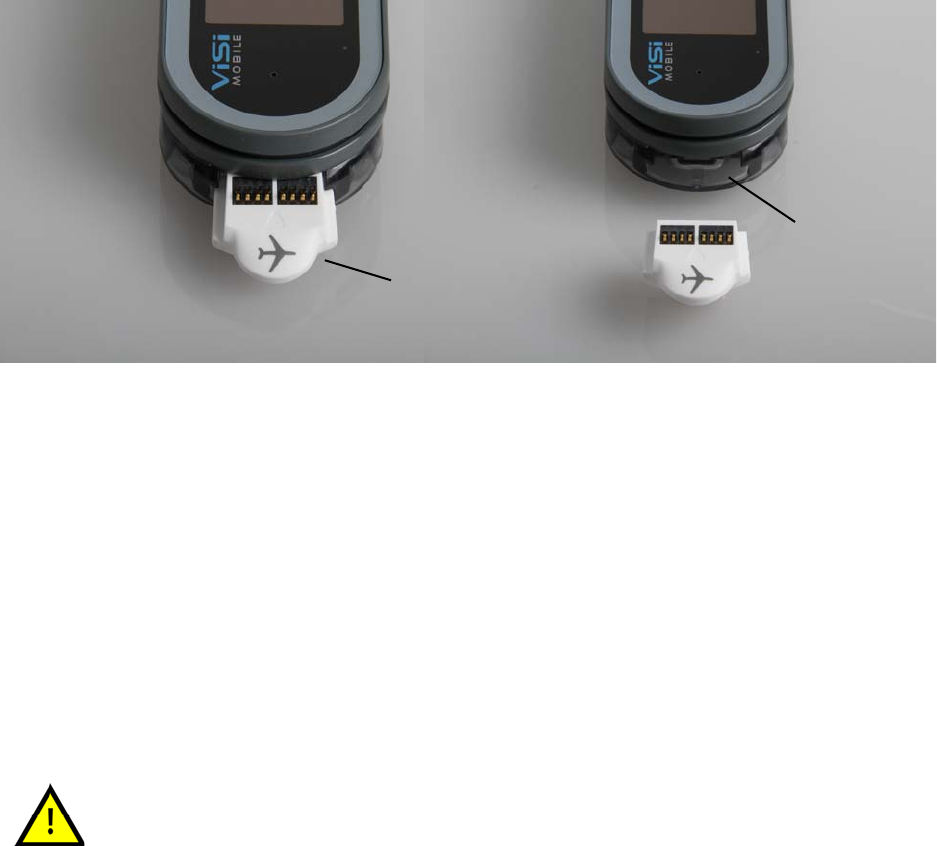
3.2.1 Removing and Inserting the Shipping Plug
All Monitors are shipped in the Wrist Cradle with a Shipping Plug (airplane symbol) inserted. This Plug is
found in the Thumb Sensor connector (on the rounded end) of the Monitor. The Shipping Plug’s only
function is to completely power off the Monitor. Reinserting the Plug into a Monitor powers down the
Monitor in a controlled fashion, and allows internal operations to be completed before completely
powering off.
To remove the Shipping Plug
Grasp the tip of the Plug that extends out from the Wrist Cradle and pull firmly outward.
The contact points are disconnected. The Monitor begins a power up phase and the initial
information screen appears.
To insert the Shipping Plug
Ensure that the ViSi Mobile Monitor is properly seated in the Wrist Cradle, the Plug is oriented
with the connector contacts facing upwards, and push in firmly.
The power down process begins. The power down cycle is complete once the screen goes blank
and the green LED indicator has stopped blinking.
If the ViSi Mobile Monitor is to be stored for an extended period of time, it is
recommended the Monitor be stored with the Shipping Plug inserted to
reduce the battery discharge. The ViSi Mobile Monitor must always have the
Shipping Plug inserted when shipped by a common carrier to comply with
Federal Regulations regarding electromagnetic emissions.
Thumb Sensor
connector
Shipping Plug
(with airplane symbol)
System Components
31
3.3 System Components
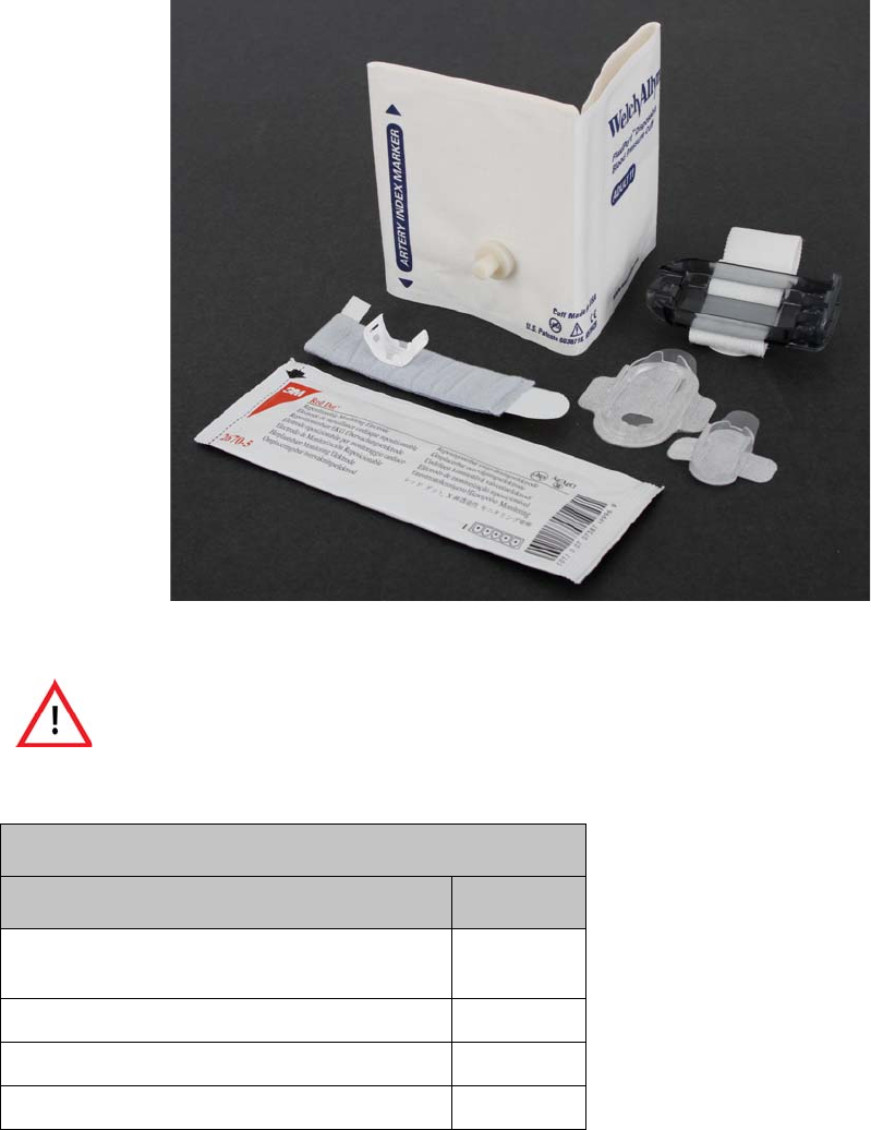
3.3.1 ViSi Mobile Disposable Kit
The Disposable Kit contains the disposable components of the system. The Disposable Kit components are
for single patient use only. The Disposable Kits are available in five adult sizes: small, medium, medium+,
large, and large+. Choose the Disposable Kit that contains the Cuff size best suited for the patient. Cuff
sizes follow standard range of arm circumference. See 5.2.5 Selecting the ViSi Mobile Disposable Kit on
page 60.
All disposable components of the ViSi Mobile Monitoring System are for
single patient use only. To avoid possible cross contamination, do not reuse
any disposable items on a patient other than the original patient. Dispose of
the components and any packaging material after use per your facility’s
policy or national requirements.
ViSi Mobile Disposable Kit Contents
Equipment Quantity
ViSi Mobile Disposable Cuff
(Welch Allyn FlexiPort Soft cuff with adaptor)
1
ECG Electrode 5
ViSi Mobile Wrist Cradle 1
ViSi Mobile Thumb Wrap 1
System Components
32
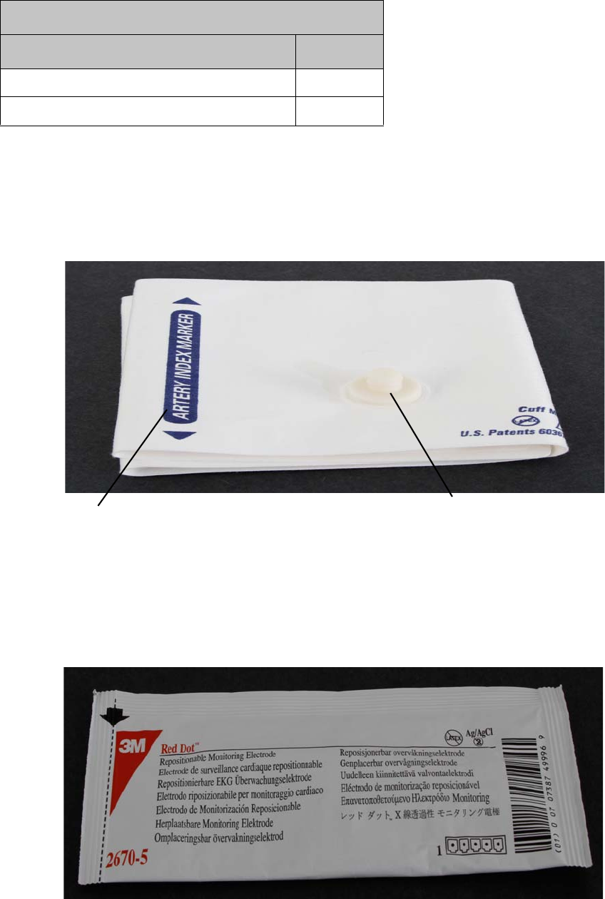
ViSi Mobile Disposable Cuff
The Cuff is available in five adult sizes: small, medium, medium+, large and large+ (see 3.3.1 ViSi Mobile
Disposable Kit on page 31). The Cuff is used to take a NIBP measurement once the Cuff Module is
attached to the Cuff and plugged into the ViSi Mobile Monitor. See 3.3.4 ViSi Mobile Cuff Module on page
37.
Note: Only cuffs designed for use with the ViSi Mobile Cuff Module may be used.
ECG Electrodes
ECG Electrodes are adhesive pads with conductive gel that are connected to the ECG lead-wires of the
Chest Sensor to display the ECG waveforms and detect the HR. Use only snap-on type electrodes.
ViSi Mobile Setup Guide 1
ViSi Mobile Cable Securement 2
ViSi Mobile Disposable Kit Contents
Equipment Quantity
Artery
Reference Line Cuff Module
Attachment
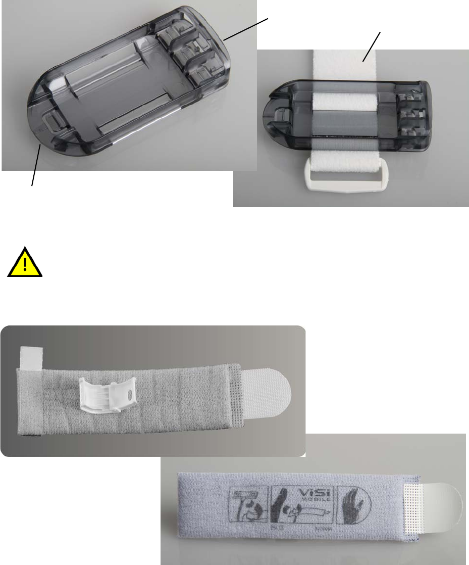
System Components
33
ViSi Mobile Wrist Cradle
The Wrist Cradle holds the Monitor and provides the connectors for the sensors. The Wrist Cradle is held
in place on the patient’s wrist with a strap.
ViSi Mobile Thumb Wrap
The Thumb Wrap holds the Thumb Sensor and secures it to the base of the thumb.
When inserting the ViSi Mobile Monitor into the Wrist Cradle, ensure proper
alignment: flat end to flat end, with the round end pointing towards the wrist.
Round End
Flat End
Wrist Cradle Strap
Bottom View
(with labelling)
Top View
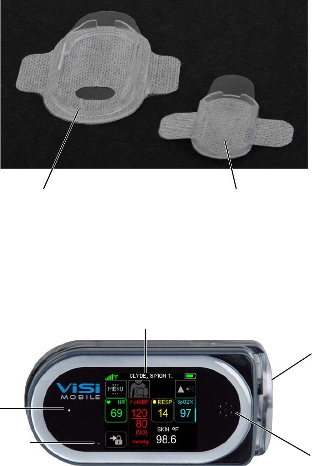
System Components
34
ViSi Mobile Chest Sensor Securements
There is one large and one small Chest Sensor Securement in the Disposable Kit. The large Securement
secures the Chest Module of the Chest Sensorto the patient’s torso. The small Securement secures the
Upper Arm Module of the Chest Sensorto the upper arm. See 3.3.5 ViSi Mobile Chest Sensor CableChest
Sensor on page 38.
3.3.2 ViSi Mobile Monitor
The Monitor is a compact and lightweight device that is worn on the patient’s wrist. The Monitor is held in
place by the Wrist Cradle, which allows sensors to be connected. The Monitor can be removed from the
Wrist Cradle in order to charge, or swap for another Monitor. The Monitor uses a touchscreen user
interface to access the displays and monitoring functions.
Note: When the Monitor is not in the Charger, the power indicator shows the approximate
monitoring time left:
Green: Battery has at least 3 hours of monitoring time left.
Yellow: Battery is low with less than 3 hours of monitoring time left.
Red: Battery is critically low with less than 1 hour of monitoring time
Securement Upper Arm Module
Securement
Chest Module
Power
Touchscreen
Speaker
Indicator
3 Interchangeable
Sensor Connections
Microphone
(for speaker self test)
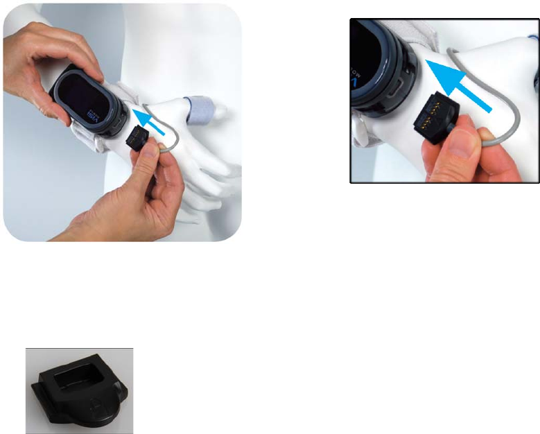
System Components
35
3.3.3 ViSi Mobile Thumb Sensor (SpO2/PR)
The Thumb Sensor is applied to the patient’s thumb and is plugged into the rounded end of the Wrist
Cradle with the connector contacts facing upwards.
Note: The Thumb Sensor locks the ViSi Mobile Monitor into the Wrist Cradle and must be
unplugged to remove the Monitor from the Wrist Cradle.
Note: A Locking Plug should be used to lock the Monitor into the Wrist Cradle if the Thumb
Sensor is not used. Locking Plugs may be ordered separately from Sotera Wireless, Inc.
Insert with connector
contacts facing upwards

System Components
36
3.3.4 ViSi Mobile Cuff Module
The Cuff Module is used to take NIBP measurements and to initiate the cNIBP calibration. The Cuff
Module plugs into any one of the connectors on the flat end of the Wrist Cradle.
For ease of use, the Monitor features three interchangeable plug-in sites for the Chest Sensor, Cuff Module,
and optional ViSi Power Pack. See “ViSi Power Pack” on page 207.
The industry-standard technique of oscillometry is used for non-invasively taking single measurements of
the systolic and diastolic blood pressure (NIBP) as well as pulse rate. The method is based on the
observation of oscillations in the sphygmomanometer cuff pressure that are caused by the oscillations of
blood flow, i.e., the pulse in the patient’s upper arm. It uses a sphygmomanometer cuff like the auscultatory
method, but with an electronic pressure sensor (transducer) to observe cuff pressure oscillations,
electronics to automatically interpret them, and automatic inflation and deflation of the Cuff. The Cuff
Module measures during Cuff inflation.
Note: When the battery status button is pressed, the battery status indicator shows the level of the
Cuff Module’s battery charge. Green lights indicate the battery has a minimum of 11%
charge. The more green lights indicate a greater charge level. A yellow light indicates the
battery charge is less than 10%. A red light indicates there is less than 4% battery charge.
Note: When a calibration check is required, return the Cuff Module to the biomedical engineer. An
annual calibration check of the Cuff Module is recommended.
Battery Status
Button
Battery Status
Indicator (LEDs)
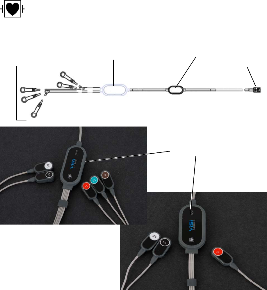
System Components
37
3.3.5 ViSi Mobile Chest Sensor
The Chest Sensor is either a 3 lead-wire or 5 lead-wire cable and plugs into any one of the connectors on
the flat end of the Wrist Cradle. See 5.3.4 Applying the ViSi Mobile Chest Sensor CableChest Sensor and
ECG Electrodes on page 69 for recommended Chest Sensor placement.
For ease of use, the Monitor features three interchangeable plug-in sites for the Chest Sensor, , Cuff
Module, or optional ViSi Power Pack.
The ViSi Mobile Chest Sensor is designed to be fully compatible with
external defibrillators. No additional precautions are required.
Upper Arm Module
Chest Module
Lead
(including Skin Temperature Sensor Monitor
Connector
on the reverse side)
Wires
Chest Sensor
5 Lead
Chest Sensor
3 Lead
Front View
(Place this side away
from the patient’s skin)
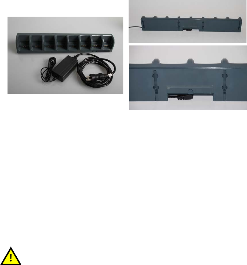
System Components
38
3.3.6 ViSi Mobile Charger
The Charger is used to charge ViSi Mobile Monitors, Cuff Modules, and ViSi Power Packs providing two
or eight charging docks for simultaneously charging multiple units.
The Charger consists of a desktop/wall mount charger, power supply and power cable.
Note: The ViSi Mobile Charger is available as a 2-bay charger or 8-bay charger (shown above).
To set up the Charger
1. Connect the power cable to the back side of the desktop/wall mount charger.
2. Plug into the AC power outlet.
The light on the front of the Charger will display green when the Charger is connected to the AC
power outlet.
The Charger will beep once when it is connected to the AC power outlet.
Note: When connected to the AC power outlet, if a fault with the ViSi Mobile Charger is detected,
the Charger will audibly beep every second.
Note: Do not position the ViSi Mobile Charger so that it is difficult to disconnect the power cable.
Explosion Hazard. Do not use in the presence of a flammable anesthetic
mixture with air, or with oxygen or nitrous oxide.
Front View
Back View
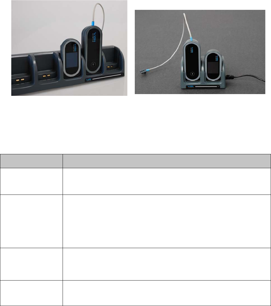
System Components
39
3.3.7 Charging the ViSi Mobile Monitor and Cuff Module
The ViSi Mobile Charger provided by Sotera Wireless, Inc. is the required Charger for both the Monitor
and the Cuff Module as well as for the optional ViSi Power Pack. The Charger is capable of charging up to
eight of any combination of Monitors, Cuff Modules and Power Packs. To charge either the Monitor or the
Cuff Module place the flat end into one of the slots with the front facing outwards.
Note: The ViSi Mobile Charger is to be used for ViSi Mobile components only.
ViSi Mobile Monitors and Cuff Modules contain sealed batteries that are not replaceable by the user.
If a Monitor or Cuff Module has a battery issue, contact the Sotera Wireless, Inc. Customer Service
Department.The LED on the Charger is used to indicate the charging status of devices that are currently
inserted:
LED Color Charging Status
Steady Green Everything is functional:
• No devices in the Charger.
• All devices are charging normally or are fully charged.
Flashing Green /
Yellow
At least one device in the Charger has not properly registered with the Charger, but
charging continues on all devices. Devices with fully drained batteries cannot register
with the Charger until after a charge cycle starts and will cause this condition until they
reach a minimum charge level. Removing and reinserting an unregistered device can
give it another chance to register in the Charger. If this condition is repeatedly observed
on devices that are not fully drained, contact Sotera Wireless, Inc. or an authorized
Sotera Wireless, Inc. representative in your area.
Steady Yellow At least one device in the Charger is not being charged due to a fault with the device.
All other devices are charging.
Contact Sotera Wireless, Inc. or an authorized Sotera Wireless, Inc. representative in
your area.
Steady Red Charger fault. No devices are charging, the Charger has shutdown.
Contact Sotera Wireless, Inc. or an authorized Sotera Wireless, Inc. representative in
your area.
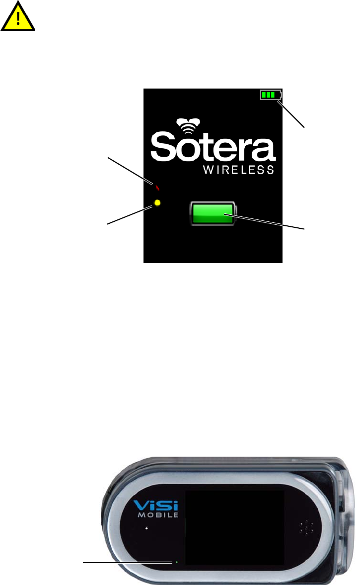
System Components
40
Charging the Monitor
Insert the Monitor that you want to charge into one of the Charger docks.
The Charge Status screen will be displayed briefly. The Monitor’s battery status indicator (in the top right
hand of the screen) stops pulsating when the battery is fully charged
Note: When the red bar is displayed on the screen, it indicates the Monitor will measure
continuous blood pressure (cNIBP) when the Chest Sensor and Thumb Sensor are connected
to a Monitor.
Note: When the yellow dot is displayed on the screen, it indicates the Monitor will measure RESP
when a Chest Sensor is connected to a patient. RESP is not available as part of the default set
of vital sign measurements and must be purchased separately.
Note: If the screen is blank, touch the screen for two seconds to activate the display and show the
battery charge status.When a Monitor that is not fully charged is removed from the Charger,
the Monitor shall beep and display the Charge Status screen. The Monitor does not have to
be fully charged in order to start monitoring. Ensure the Monitor has been charged
sufficiently before monitoring is started.
When the ViSi Mobile Monitor is in the Charger and a charging alert occurs,
remove the Monitor from service.
In Charger
Battery Charging Indicator
(pulsates as battery is charging)
RESP measurement
option is available
Battery Status
Indicator
cNIBP measurement
option is available
Power
Indicator
System Components
41
Note: When the Monitor is in the Charger, the power indicator shows the charging state:
Green: The Monitor is fully charged.
Yellow: The Monitor is still charging
The charge level (when the Monitor is in the Charger) is different from the monitoring time
remaining (when the Monitor is out of the Charger).
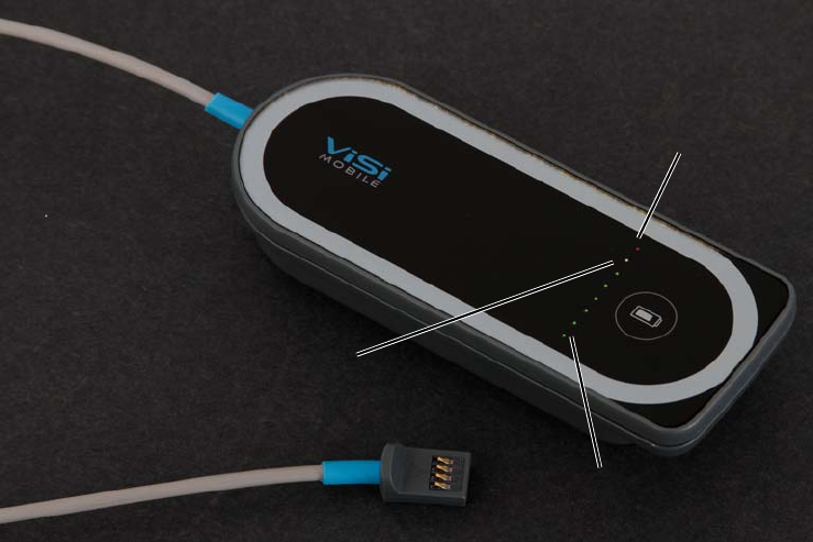
System Components
42
Charging the Cuff Module
Insert the Cuff Module that you want to charge into one of the Charger docks.
One of the charging indicator lights will blink while the Cuff Module is charging.
When one of the green charging indicators is flashing, the battery in the Cuff Module is charging. The
position of the green charging indicator represents the level of charge. When the charge indicator furthest
away from the red charging indicator is flashing, the Cuff Module is fully charged.
When the yellow charging indicator is flashing, the battery in the Cuff Module is low. At least one
additional measurement may be taken.
When the red charging indicator is flashing, the battery in the Cuff Module has insufficient charge to take
a measurement. No cuff inflations are possible.
Charging the Optional ViSi Power Pack
See “ Charging the ViSi Power Pack on page 212”
Battery is empty
Battery is fully charged
Battery is low
(Red LED)
(Yellow LED)
(Green LED)
System Components
43
System Components
44

45
4. Clinical Features
4.1 Introduction
The ViSi Mobile Monitor is completely body-worn and designed to continuously measure ECG/HR, SpO2,
PR, RESP, and TEMP. The ECG, SpO2, and RESP waveforms are viewable on demand. NIBP can be
measured as a one-time measurement, automatically at predefined intervals or continuously.
The Chest Sensor measures the ECG/HR, RESP, and TEMP. The illustration on the next page shows a 3
lead-wire placement.
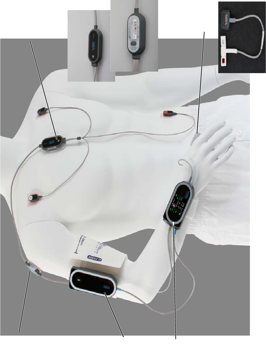
Introduction
46
Upper Arm Module
Monitor
Thumb Sensor
Chest Module
(in Wrist Cradle)
Cuff Module
ViSi Mobile Monitoring System Setup
(Flat End)
(Round End)
(in Securement
with Leads
Front
Temperature Probe
(Place against patient’s skin)
(Place away from patient’s skin)
(in Securement)
(on Blood Pressure
Cuff)
pointing down)
(with Thumb Wrap)

Key Features
47
4.2 Key Features
• Chest Sensor options: 3 lead-wire and 5 lead-wire (HR and ECG waveforms)
• RESP (measurement and waveform)
•SpO
2% (measurement and waveform)
• TEMP (oC/oF) (Skin Temperature measurement)
• NIBP (single measurement, automatic measurements at predefined cycles and continuously)
• Touchscreen display
• Alarms and Alerts generated with visual and audible indication on the Monitor
• Self Test
4.3 Overview of Clinical Features
The ViSi Mobile Monitoring System is a lightweight portable patient vital signs monitor featuring a high
resolution, full color display with visual and audible alarms and alerts. The ViSi Mobile Monitor is
completely body-worn and designed to continuously measure ECG/HR, SpO2, PR, RESP, NIBP and
TEMP. The ECG, SpO2, and RESP. Waveforms are viewable on demand. NIBP can be measured as a one-
time measurement, automatically at programmed intervals or continuously.
The Monitor is powered by a rechargeable battery. For ease of use, the Monitor features interchangeable
plug-in sites for the ViSi Mobile Chest Sensor and ViSi Mobile Cuff Module. The Chest Sensor measures
the ECG/HR (with a 3 lead-wire or 5 lead-wire), RESP, and TEMP.
4.3.1 ECG Monitoring and Heart Rate (HR) Monitoring
With the 3 lead-wire Chest Sensor, the Monitor continuously monitors Lead II.
With the 5 lead-wire Chest Sensor, the Monitor continuously monitors seven ECG lead views
simultaneously, Leads I, II, III, aVR, aVL, aVF, and a V lead. The ECG waveform can be displayed one
lead at a time.
The ability to monitor multiple leads simultaneously improves beat detection to determine the HR and
minimizes false detections as a result of muscle artifact.
4.3.2 Respiration Rate (RESP) Monitoring
RESP is determined by measuring the AC impedance between the RA and LL ECG electrodes. Chest wall
motion, rise and fall, associated with inspiration and expiration is automatically detected when the RA and
LL leads are placed in the standard Lead II configuration on the chest, or in the MCL II position.
RESP is determined from the frequency of the respiration (chest wall motion). The respiration channel can
detect the absence of RESP.
Note: Respiration rate monitoring is an optional feature that requires an additional license key.
RESP (chest wall motion) can continue in the absence of ventilation
(obstructed airway). Do not rely on the RESP alone to determine adequacy
of ventilation. Other vital signs, such as HR and SpO2, should be assessed
as well.

Overview of Clinical Features
48
4.3.3 Skin Temperature (TEMP) Monitoring
TEMP continuously measures skin temperature using the sensor located on the underside of the Chest
Module. The sensor must be placed directly in contact with the patient’s skin. TEMP can be displayed in
°C or °F. See To apply the Chest Sensor CableChest Sensor on page 72.
Note: Skin temperature is not synonymous with core body temperature or temperature measured
using the oral or tympanic methods.
Note: Skin temperature representative of skin surface temperature will take approximately 6
minutes from the time the Chest Module is applied.
4.3.4 Pulse Oximetry (SpO2 and Pulse Rate) Monitoring
The Pulse Oximetry channel non-invasively and continuously measures the functional oxygen saturation
of the hemoglobin in arterial blood using the transmittance across the base of the thumb. A pulsatile
arterial source at the base of the thumb is required to measure the SpO2.
In the absence of a heart rate source from an ECG, the pulse rate can be measured and displayed from the
SpO2 channel.
When turned on, the tone pitch of the heart beat will change with the level of oxygen saturation. A higher
pitch is associated with higher SpO2 levels.
4.3.5 NIBP Monitoring
The ViSi Mobile Cuff Module is intended for measuring arterial blood pressure (systolic, diastolic and
MAP) using a Cuff. Measurements may be initiated manually (one at a time), automatically at selectable
predefined intervals of 5, 10, 15, 30, 60, 90 and 120 minutes or continuously.
TEMP monitoring with the ViSi Mobile Monitoring System is intended for
trending purposes only and is not intended to replace core temperature
monitoring. Before making clinical decisions based on the skin temperature
measurement, verify the measurement using another clinically acceptable
method of core temperature measurement.
Oxygen saturation measurements using SpO2 are dependent on proper
sensor placement, exposure to ambient light conditions, and general patient
conditions. Before making clinical decisions based on SpO2 measurements,
verify the measurement using another clinically acceptable method, such as
arterial blood gas analysis.
High ambient light conditions, including direct sunlight, may interfere with
the performance of the ViSi Mobile Thumb Sensor.
Low perfusion, electrosurgical devices, dysfunctional hemogolobin, the
presence of certain dyes and inappropriate positioning of the ViSi Mobile
Thumb Sensor may result in erroneous measurements.

Overview of Clinical Features
49
The accuracy of NIBP measurements is influenced by several factors:
• Correct cuff size
• Correct cuff placement on the arm
• The position of the upper arm in relation to the heart at the time of the measurement
• Motion artifacts
Note: To measure continuous non-invasive blood pressure (cNIBP), the Cuff Module is only
required for the initial inflation to determine the Pulse Arrival Time (PAT) and for periodic
recalibrations.
Avoid touching the ViSi Mobile Disposable Cuff during cuff inflation as it may
disrupt the measurement.
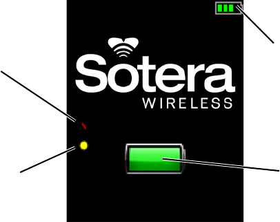
Display Screens
50
4.4 Display Screens
This section describes various screens displayed on the ViSi Mobile Monitor. Each screen is accessed by
interacting with the touchscreen display.
4.4.1 Battery Charge Screen
The Battery Charge screen displays the battery status while the Monitor is charging in the Charger.
Note: When the red bar is displayed on the screen, it indicates the Monitor will measure
continuous blood pressure (cNIBP) when the Chest Sensor, Cuff Module and Thumb Sensor
are connected to a Monitor.
Note: When the yellow dot is displayed on the screen, it indicates the Monitor will measure RESP
when a Chest Sensor is connected to a Monitor.
Note: cNIBP and RESP measurements are not available as part of the default set of vital sign
measurements and must be purchased separately.
Battery Status
Battery Charging Indicator
(pulsates as battery is charging)
Indicator
RESP measurement
option is available
cNIBP measurement
option is available
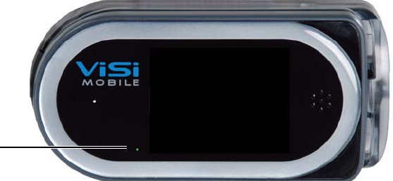
Display Screens
51
4.4.2 Hibernation Screen
The Hibernation screen (blank screen) is the default when no monitoring is currently in progress.
The Hibernation screen conserves battery power under the following conditions:
• The Shipping Plug is not plugged into the Monitor
• The Monitor is not in the Charger
• No sensors are connected to the Monitor
Note: When the Monitor is not in the Charger, the power indicator shows the approximate
monitoring time left:
Green: Battery has at least 3 hours of monitoring time left.
Yellow: Battery is low with less than 3 hours of monitoring time left.
Red: Battery is critically low with less than 1 hour of monitoring time.
Note: Connecting a sensor to the Monitor displays the Vital Sign screen. There will be a brief delay
before the Vital Sign screen is displayed to allow the Monitor’s self test to complete.
Power
Indicator
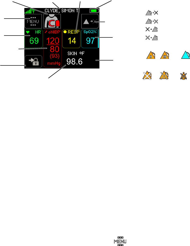
Display Screens
52
4.4.3 Vital Signs Screen
The Vital Signs screen is the default screen that displays automatically (on initial setup) when sensors are
placed on the patient and connected to the Monitor.
Use the Vital Signs screen to:
• View current vital sign measurements
• Vital Signs Measurement: Access the waveforms (see page 117)
• Alarm Status: View alarm status
• Battery Status Indicator: View the battery status
• Menu: Access the Menu screen (see page 53)
• Start/Stop NIBP: Start and stop manual NIBP measurement (see page 124)
• Calibrate NIBP for continuous monitoring of blood pressure (see page 128).
• Alarm Management: Pause alarms/alerts (see page 91)
• Alarm Management: Acknowledge (silence) alarms/alerts (see pages 85 and 89)
• Lock: Lock the Monitor to prevent unauthorized access
Note: Systolic, diastolic and MAP measurements of cNIBP will be displayed in red when
measuring NIBP continuously. Spot-check NIBP measurements are displayed in white.
Note: A respiration measurement will not be displayed until 60 seconds have elapsed since the time
the ECG leads were connected to the patient and 6 breaths have been identified.
4.4.4 Menu Screen
Touch Menu on the Vital Sign screen to view the Menu screen.
Use the Menu screen to:
• Change the NIBP measurements between Manual, Auto (including setting the auto inflation
interval) and continuous. (see page 127)
Battery Status
Menu
Lock
RESP
Sp02
TEMP
Start/Stop NIBP
Continuous NIBP
Alarm
Message area
HR/PR
Indicator
Calibrate cNIBP
Alarm Status
Management
Pause
Turn Off
Resume
Turn On
Alarm Alert
Alarms Alarms Alarm
in progress In progress
Off Paused Acknowledged
(Patient’s Primary ID)
Sys / Dia / MAP
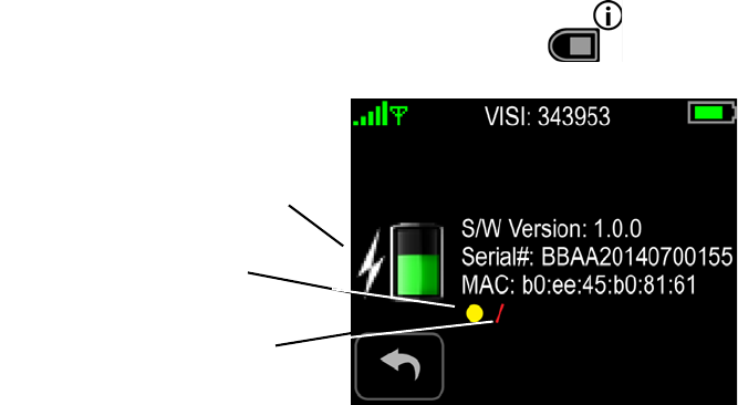
Display Screens
53
• Pause or stop monitoring (see pages 139 and 142)
• View Monitor status
• View and change the alarm limits settings (see page 96)
• View patient demographics (see page 135)
• Select the patient’s current posture (see page 132).
Note: Silence or enable the QRS/PR beep toneThe Select Patient’s Posture button will be enabled
when the ViSi Mobile Chest Sensor is connected to the Monitor.
Note: When turned on, the tone pitch of the heart beat will change with the level of oxygen
saturation. A higher pitch is associated with higher SpO2 levels.
4.4.5 Monitor Status Screen
Touch Monitor Status on the Menu screen to access the Monitor Status screen.
Use the Monitor Status screen to:
• View the battery status
• View the version of the Monitor’s software
• View the Monitor’s serial number
• View the Monitor’s MAC address
• View the licensed features that are available, such as RESP and continuous NIBP
• View the battery status of the Power Pack, if connected
4.4.6 Quiet Monitoring Screen
The Quiet Monitoring screen (blank screen) is the default when sensors are connected both to the Monitor
and the patient and no user interaction has occurred for a predefined period of time. Continuous
monitoring is in progress during this time.
Note: After a predefined period of no direct interaction with the Monitor, the Monitor locks
automatically and enters Quiet Monitoring.
The Quiet Monitoring Screen conserves battery power and minimizes patient disturbance. Vital signs
alarms and alerts remain active. Touching the screen continuously for 2 seconds resumes the Monitor’s
display with the Patient View screen.
Power Pack battery status indicator
The yellow dot indicates RESP is
(when connected to Power Pack)
available with this Monitor
The red bar indicates cNIBP is
available with this Monitor
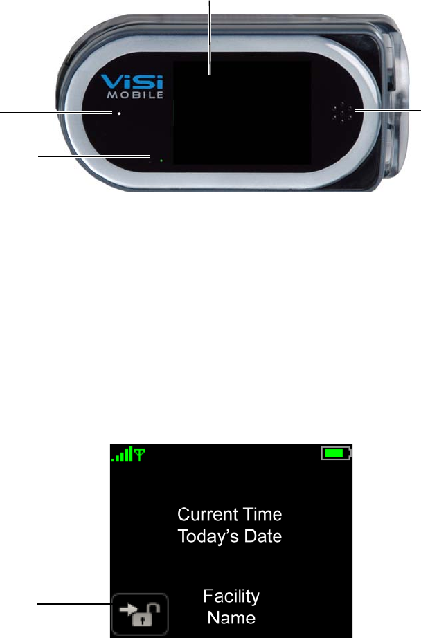
Display Screens
54
Note: When the Monitor is not in the Charger, the power indicator shows the approximate
monitoring time left:
Green: Battery has at least 3 hours of monitoring time left.
Yellow: Battery is low with less than 3 hours of monitoring time left.
Red: Battery is critically low with less than 1 hour of monitoring time.
4.4.7 Patient View Screen
The Patient View screen appears whenever the touchscreen is touched continuously for 2 seconds during
Quiet Monitoring.
Use the Patient View screen to:
• View the current time
• View battery charge level
• Unlock the Monitor
Power
Touchscreen
Speaker
Indicator
Microphone
UUnlock
Display Screens
55
- Notes -
Display Screens
56

57
5. Operation
5.1 Introduction
The ViSi Mobile Monitoring System is a sophisticated multi-parameter vital signs monitor. In order to
optimize the user of ViSi, please adhere to the following instructions related to patient set-up, initiating
monitoring and the removal of the System.
5.2 Preparing for a New Patient
In order to set up the complete ViSi Mobile Monitoring System, you will need the following components:
• ViSi Mobile Disposable Kit (select size)
• ViSi Mobile Monitor
• ViSi Mobile Cuff Module
• ViSi Mobile Thumb Sensor
• ViSi Mobile Chest Sensor (3 lead-wire or 5 lead-wire configuration)
Note: Skin preparation equipment (skin preparation pads, scissors and/or razor as needed) is not
included.
5.2.1 Inspecting the Equipment and Accessories
Before starting patient monitoring, you should visually inspect the ViSi Mobile Monitoring System
components:
1. For each component, examine the exteriors for cleanliness and general physical conditions.
Ensure the housings are not cracked or broken, that everything is present, there are no spilled
liquids and no signs of abuse.
2. Inspect all component cables for damage. Check their strain relief (at flex points) for general
condition. Ensure there are no breaks or cracks in the cables . If any cables show signs of damage,
do not use.
3. Inspect all disposable accessories (Wrist Cradle, Cuff, Thumb Strap, Securements, etc). If any
show signs of damage or pre-use, do not use.
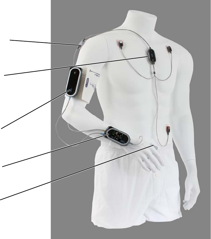
Preparing for a New Patient
58
5.2.2 Applying Sensors
Applying the sensors is simple and may be done in any order. At the completion of the setup, the
components of the ViSi Mobile Monitoring System will be connected to the patient as shown in the
diagram below.
Whenever a sensor is connected to the Monitor, a self-test of that sensor is initiated automatically to verify
the sensor is in good working order. If the sensor and Monitor speaker are in good working order, you will
hear a double beep. This process takes a few seconds, after which monitoring of the selected vital sign
commences as soon as the sensor is connected to the patient.
The double beep is also a validation that the Monitor speaker is in good working order and that audio tones
associated with alarms will be annunciated accordingly.
Alarm limits are set automatically according to default settings. See 6.6 Manage Alarm Limits on page 96.
Monitor
Thumb Sensor
Cuff Module
(Applied to upper arm)
(in Wrist Cradle)
Upper Arm Module
(on Chest Sensor in
Chest Module
(on Chest Sensor in
(in thumb wrap)
the Securement)
the Securement)
(Temperature probe on the
back side of the Chest
Module must be placed
against the patients skin)
Preparing for a New Patient
59
Successful vital signs monitoring is dependent on several factors:
• Determining the vital signs to be monitored
• Selecting a Monitor and Cuff Module that are adequately charged for maximum duration of
uninterrupted monitoring
• Selecting the 3 lead-wire or 5 lead-wire Chest Sensor
• Selecting the appropriately sized Cuff (from the Disposable Kit)
• Preparing the skin for ECG electrode placement
• Correctly applying all sensors used for monitoring
Note: The battery in the Monitor will deplete at a faster rate when sensors are connected to the
Monitor, even when monitoring has not been started.
Note: The Chest Module includes a body surface temperature sensor. To ensure proper function,
place the temperature sensor on the body with the Chest Module “Front” label facing
forward (away from the patient’s skin).
5.2.3 Selecting Vital Signs to Monitor
The following vital signs may be monitored:
• Chest Sensor (one or seven simultaneous leads, using the 3 lead-wire or 5 lead-wire Chest Sensor
respectively)
HR (from the ECG)
RESP (optional)
TEMP (Skin Temperature)
• Thumb Sensor
SpO2
PR (from the Thumb Sensor)
• Cuff Module (single measurement, automatically at set intervals or continuously)
SYS
DIA
MAP
PR (from NIBP)
5.2.4 Selecting the ViSi Mobile Chest Sensor
The Chest Sensor provides the sensors to monitor the ECG, HR, RESP (optional), and TEMP.
Note: The skin surface temperature sensor is on the underside of the Chest Module. It must be
placed on the skin surface in order to properly measure skin surface temperature.
Select the Chest Sensor that best suits the monitoring needs of your patient:
• The 3 lead-wire Chest Sensor monitors Lead II, or the MCL configuration.
• The 5 lead-wire Chest Sensor monitors seven leads of ECG simultaneously in lead configurations
I, II, III, aVR, aVL, aVF, and a V lead. The specific V lead depends on the placement of the V
electrode.
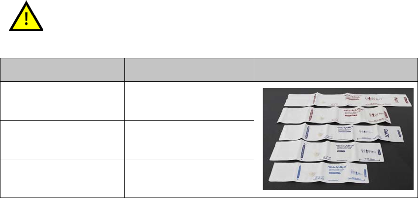
Preparing for a New Patient
60
5.2.5 Selecting the ViSi Mobile Disposable Kit
The System’s disposable components, including the Cuff are contained in the Disposable Kit. The
Disposable Kits are designated as S, M, M+, L and L+ based on the Cuff size.
5.2.6 Checking the Battery Charge of the ViSi Mobile Monitor
and Cuff Module
Before you start to monitor your patient with the System, you will need to select both a Monitor and a Cuff
Module that are adequately charged for maximum duration of uninterrupted monitoring.
To check the battery charge of the Monitor
1. Turn on the display by touching the screen while the Monitor is in the Charger.
2. Review the large battery icon in the center of the screen.
The battery color should be interpreted as follows:
• When the battery is green, the battery is at least 90% charged.
• When the battery is yellow, the battery is charged between 40% and 90%.
• When the battery is red, the battery charge is less than 40%.
Selection of the correct ViSi Mobile Disposable Cuff size is necessary to
ensure accurate NIBP measurements. A Cuff that is too small can result in a
falsely high NIBP measurement. A Cuff that is too large can result in a
falsely low NIBP measurement.
Cuff / Disposable Kit Size Arm Circumference (cm)
Adult S 20 – 26
Adult M / M+ 25 – 34
Adult L / L+ 32 – 43

Preparing for a New Patient
61
A red battery symbol indicates the battery is critically low with less than 30 minutes of monitoring time left.
Note: When the red bar is displayed on the screen, it indicates the Monitor will measure
continuous blood pressure (cNIBP) when a Chest Sensor and Thumb Sensor are connected
to a Monitor.
Note: When the yellow dot is displayed on the screen, it indicates the Monitor will measure RESP
when a Chest Sensor is connected to a Monitor.
Note: cNIBP and RESP measurements are not available as part of the default set of vital sign
measurements and must be purchased separately.
Fully Charged
Battery Low
Battery Critically Low
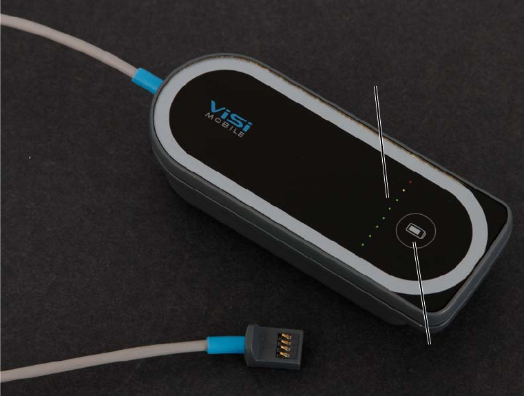
Preparing for a New Patient
62
To check the battery charge of the Cuff Module
Press the Battery Status button on the front of the Cuff Module.
There is a row of eight colored lights on the front surface of the Cuff Module.
Illuminated green lights indicate that the level of the battery charge is adequate for at least several NIBP
measurements. When six illuminated green lights are visible on the Cuff Module, the Module is fully
charged.
When the yellow light is illuminated, the battery charge is low. At least one NIBP measurement is possible.
When the red light is illuminated, the battery charge is too low for any further NIBP measurements.
Battery Status
button
Battery Status
Indicator (LEDs)

Applying ViSi Mobile Monitoring System / Initiate
63
5.3 Applying ViSi Mobile Monitoring System / Initiate
Monitoring
The ViSi Mobile Monitor may be used to monitor one vital sign, such as SpO2, or multiple vital signs
simultaneously. Apply the appropriate sensor for each vital sign to be monitored, as described below. Start
by selecting the appropriately sized Disposable Kit (S, M, M+, L or L+).
The Monitor’s ECG channel is capable of monitoring patients with an Implanted Pacemaker (PM),
Implantable Cardioverter-Defibrillator (ICD), or Cardiac Resynchronization Therapy (CRT) device. A
vertical dashed line before the P wave (atrial pace), and before the QRS (ventricular pace) indicates paced
events. In the case of biventricular pacing (CRT), two vertical dashed lines occur before the QRS.
Note: Vertical dashed lines from pacemaker stimulus pulses may occur. These are not counted as
heartbeats, as defined by the pacer pulse rejection specification. See Chapter 10.
Specifications on page 161.
Pacemaker signals can differ among pacemakers, ICDs, or CRT devices.
The Association for the Advancement of Medical Instrumentation (AAMI)
cautions: “In some devices, rate meters may continue to count the
pacemaker rate during occurrences of cardiac arrest or some arrhythmias.
Do not rely entirely upon rate meter alarms”. All pacemaker patients should
be kept under close or constant observation.
External pacemakers or other external electrical stimulators may cause the
ViSi Mobile Monitor to produce erroneous results.
ViSi cNIBP has not been evaluated in patients with pacemakers that pace
the ventricle. ViSi’s NIBP may be used instead.
Only use the ViSi Mobile Chest Sensor CableChest Sensor
provided by Sotera Wireless, Inc. for the ViSi Mobile Monitoring
System. The Chest Sensor CableChest Sensor is designed to
provide defibrillation protection as indicated in the Specifications
section of this manual. ViSi Mobile is designed to be compatible
with the use of external defibrillators.
Only use the ViSi Mobile Thumb Sensor provided by Sotera Wireless, Inc.
with the ViSi Mobile Monitoring System. Using non-approved Thumb
Sensors may result in inaccurate SpO2 readings or damaged equipment.
All disposable components of the ViSi Mobile Monitoring System are for
single patient use only. To avoid possible cross contamination, do not reuse
any disposable items on a patient other than the original patient. Dispose of
the components and any packaging material after use per your facility’s
policy or national requirements.
The ViSi Mobile Monitor, Thumb Sensor, Cuff Module, and the Chest
Sensor CableChest Sensor must all be connected to the same arm for the
System to function correctly.
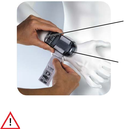
Applying ViSi Mobile Monitoring System / Initiate Monitoring
64
5.3.1 Applying the ViSi Mobile Wrist Cradle
If there are no contraindications, apply the Wrist Cradle to the patient’s wrist (either left or right).
To apply the Wrist Cradle
1. Remove the Wrist Cradle from the Disposable Kit.
2. Orient the Wrist Cradle with the flat end pointed towards the elbow, slide the patient’s hand
through the Wrist Strap and position the cradle on the top side of the wrist.
3. Pull snugly and secure.
4. Placing the flat end in first, insert the Monitor into the Wrist Cradle and push down.
The Wrist Strap should securely hold the ViSi Mobile Wrist Cradle in place
without impairing circulation. Immediately loosen the Wrist Strap if the
patient complains of pain, tingling, or numbness in the affected hand or
wrist.
Rounded
End
Flat End
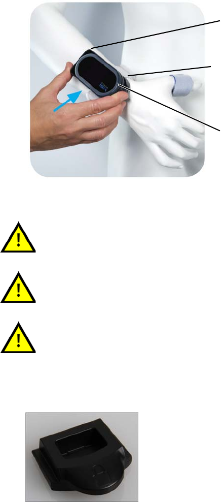
Applying ViSi Mobile Monitoring System / Initiate
65
When the Monitor is pushed down all the way, you will hear a “clicking” sound.
Note: The Monitor is not completely secured within the Wrist Cradle until the Thumb Sensor or
Locking Plug is inserted into the connector on the rounded end of the Monitor.
5. If you are not performing SpO2 monitoring, secure the Monitor to the cradle by inserting a Locking
Plug into the opening on the rounded end of the Monitor.
When inserting the ViSi Mobile Monitor into the Wrist Cradle, ensure proper
alignment: flat end to flat end, with the round end pointing towards the wrist.
To avoid damage from dropping the ViSi Mobile Monitor, ensure that the
Wrist Strap is snugly wrapped around the wrist.
To avoid damage from dropping the ViSi Mobile Monitor while it is
connected to the patient, secure the ViSi Mobile Monitor by plugging in the
thumb sensor or locking key.
Rounded
End
Flat End
Wrist Cradle
Locking Plug
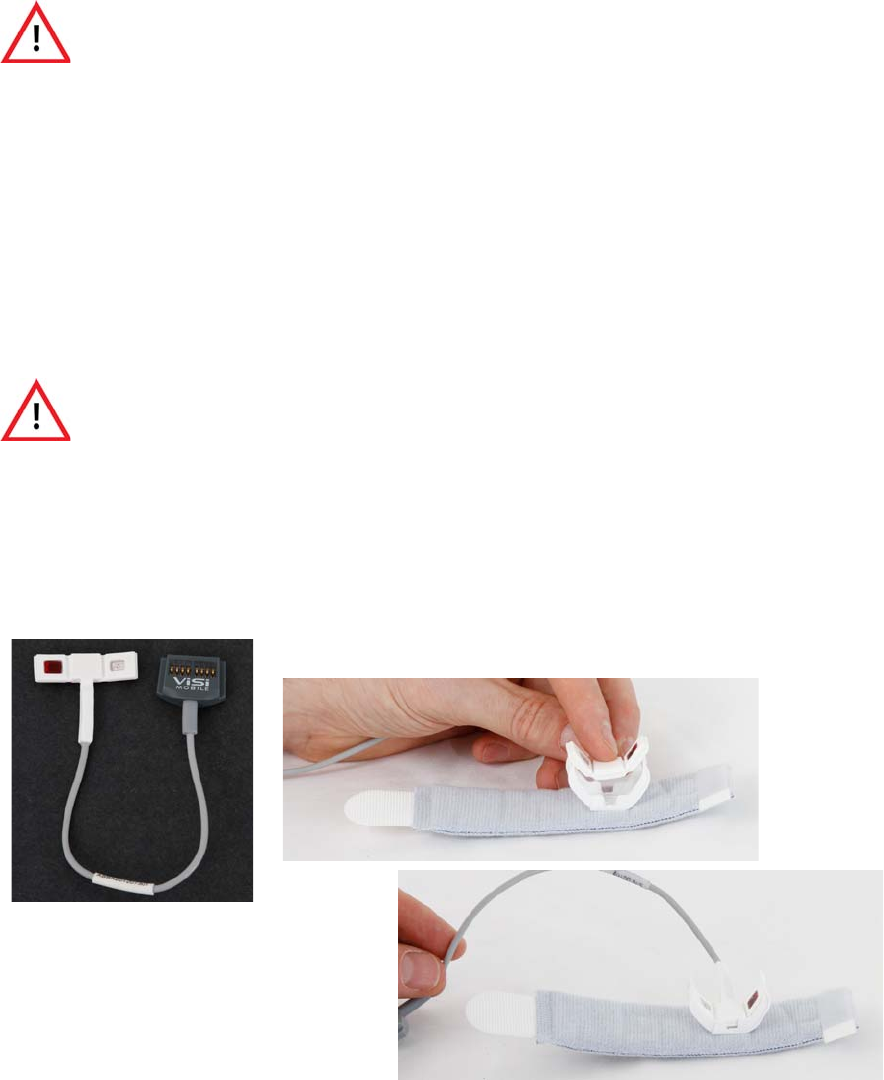
Applying ViSi Mobile Monitoring System / Initiate Monitoring
66
5.3.2 Applying Sensors
Vital signs monitoring starts automatically as soon as a sensor is connected to the Monitor and attached to
the patient. When performing a patient setup, the alarms pause automatically, allowing time to complete
the setup before the alarms are turned on.
Sensors are designed to securely plug into the Monitor so that they cannot fall out unintentionally.
You should hear a double-beep sound when a sensor is inserted correctly.
5.3.3 Applying the ViSi Mobile Thumb Sensor
To apply the Thumb Sensor
1. Remove the Thumb Wrap from the Disposable Kit.
2. Insert the Thumb Sensor into the Thumb Wrap such that the sensor optics are pointing away from
the Thumb Wrap.
The ViSi Mobile Monitor, Thumb Sensor, Cuff Module, and the Chest Sensor
CableChest Sensor must all be connected to the same arm for the System
to function correctly.
The ViSi Mobile Thumb Sensor is intended for use on the patient’s thumb,
index and middle finger for SpO2 measurements; however, cNIBP can only
be measured while on the patient’s thumb. only. Do not apply the Thumb
Sensor to the patient’s fingers.
Thumb Wrap
Thumb Sensor
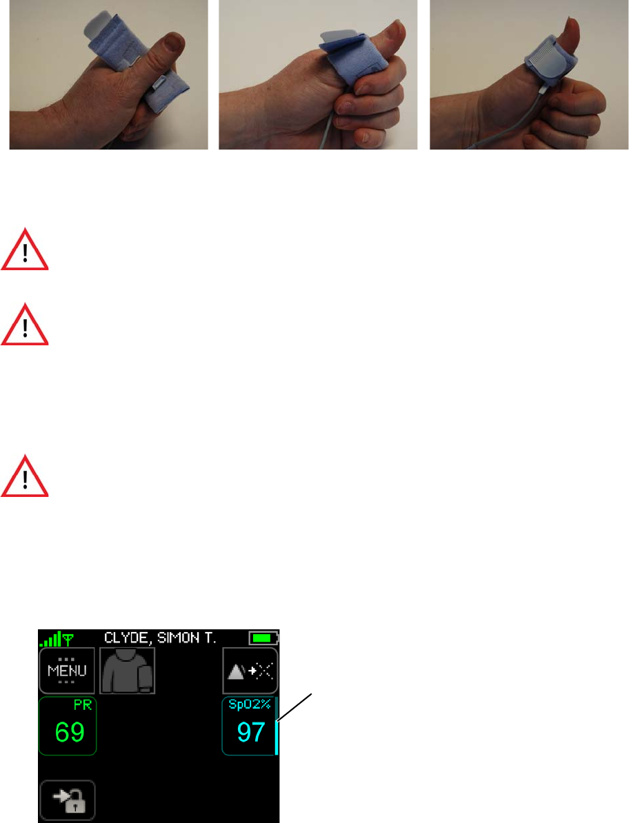
Applying ViSi Mobile Monitoring System / Initiate
67
3. Remove the plastic from the adhesive strip to minimize movement and rotation of the Thumb
Wrap.
4. Place the Thumb Sensor at the base of the thumb and secure it with the Thumb Wrap.
The Thumb Wrap is designed to hold the Thumb Sensor in place securely without impairing
circulation.
5. Check the patient’s thumb for good color and circulation to ensure that the Thumb Sensor has not
restricted circulation.
6. Connect the Thumb Sensor into the connector on the rounded end of the Monitor with the
connector contacts facing upwards.
The monitoring of SpO2 and the PR starts after a few seconds. Alarm limits are set automatically
according to predefined settings. See 6.6 Manage Alarm Limits on page 96.
Ensure that the ViSi Mobile Thumb Sensor is securely fastened. A Thumb
Sensor that is wrapped too tightly or too loosely can adversely affect SpO2
measurement.
Inspect the patient’s skin at the sensor site per your facility’s protocol. If the
skin surface has been compromised, reposition the ViSi Mobile Thumb
Sensor or move the Thumb Sensor to the patient’s other thumb. If the thumb
sensor is moved to the other thumb, move the other sensors as well.
The Thumb StrapWrap should securely hold the ViSi Mobile Thumb Sensor
in place without impairing circulation. Immediately loosen the Thumb
StrapWrap if the patient complains of pain, tingling, or numbness in the
affected thumb.
Pulsating
Indicator Bar

Applying ViSi Mobile Monitoring System / Initiate Monitoring
68
7. While palpating the pulse in the wrist of the arm opposite the Monitor, watch the pulsating
indicator bar to the right of the SpO2 numeric and ensure that the bar fluctuates with the pulse.
The pulsating indicator bar confirms signal adequacy by moving up and down in sync with the
detection of pulsating blood flow. Use the pulsating indicator bar to confirm the Thumb Sensor is
optimally placed. It may take several seconds for the signal to stabilize.
The indicated PR should match the palpated pulse rate. PR is replaced with HR when measuring
ECG and SpO2 simultaneously.
Note: If sensing of the SpO2 or the PR is erratic, loosen the Thumb Strap from the thumb and
reposition the Thumb Sensor until a stable SpO2 and PR are obtained. Re-secure the Thumb
Sensor with the Thumb Strap.
Note:
Only use the ViSi Mobile Thumb Sensor provided by Sotera Wireless, Inc.
with the ViSi Mobile Monitoring System. Using non-approved Thumb
Sensors may result in inaccurate SpO2 readings or damaged equipment.

Applying ViSi Mobile Monitoring System / Initiate
69
5.3.4 Applying the ViSi Mobile Chest Sensor and ECG Electrodes
Skin Preparation
Skin preparation and ECG electrode placement directly impact the quality of the ECG signal and HR
determinations. Follow your facility’s protocol for skin preparation.
Note: To avoid skin irritation, avoid areas that appear damaged; remove ECG electrodes if the
patient complains of pain/itching; replace ECG electrodes per the electrode manufacturer’s
instructions and place on different sites.
Note: Only use snap-on type electrodes.
Use all of the same type of high quality ECG electrodes on the patient.
Mixing ECG electrode types can adversely affect ECG monitoring.
To ensure patient safety, use only components and accessories
recommended or supplied by Sotera Wireless, Inc. Accessories must
always be used in accordance with your facility’s policies and the
manufacturer’s recommendations.
Only use the ViSi Mobile Chest Sensor CableChest Sensor
provided by Sotera Wireless, Inc. for the ViSi Mobile Monitoring
System. The Chest Sensor CableChest Sensor is designed to
provide defibrillation protection as indicated in the Specifications
section of this manual. ViSi Mobile is designed to be compatible
with the use of external defibrillators.
To ensure patient safety, the conductive parts of the ECG electrodes,
including connectors and other patient-applied components, should not
contact other conductive parts, or earth ground, at any time.
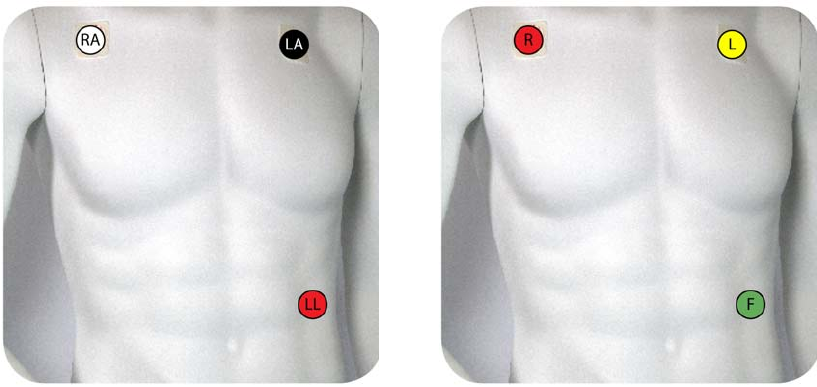
Applying ViSi Mobile Monitoring System / Initiate Monitoring
70
3 lead-wire and ECG Electrode Placement
With the 3 lead-wire Chest Sensor, the ECG channel provides Lead II only. The ECG electrode placement
shown in the diagram below is recommended for Lead II monitoring
lead-wire Color Code - U.S. (AAMI)
RA - White
LA - Black
LL - Red
lead-wire Color Code - International (IEC)
R - Red
L - Yellow
F - Green
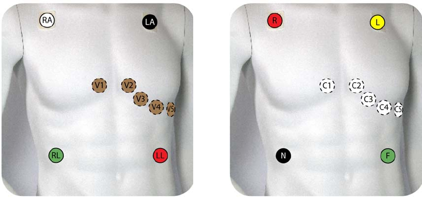
Applying ViSi Mobile Monitoring System / Initiate
71
5 lead-wire and ECG Electrode Placement
With the 5 lead-wire Chest Sensor, the ECG channel is capable of monitoring seven leads simultaneously
(Lead I, II, III, aVR, aVL, aVF, and a V lead). The ability to monitor multiple leads simultaneously
improves beat detection to determine the HR and minimizes false detections as a result of artifact. The
ECG electrode placement shown in the diagram below is recommended.
Note: Place the V lead in the position appropriate to your monitoring requirements: V1, V2, V3,
V4, V5 or V6.
Note: The ECG waveform can be displayed one lead at a time on the ViSi Mobile Monitor.
V1/C1 4th intercostal space (just right of sternum)
V2/C2 4th intercostal space (just left of sternum)
V3/C3 Midway between V2 and V4
V4/C4 Mid clavicular line, 5th intercostal space
V5/C5 Anterior axillary line, in line with V4, or 5th intercostal space
V6/C6 Mid axillary line, in line with V5, or 5th intercostal space
lead-wire Color Code - U.S. (AAMI)
RA - White
LA - Black
LL - Red
lead-wire Color Code - International (IEC)
R - Red
L - Yellow
F - Green
V - Brown
RL - Green C - White
N - Black
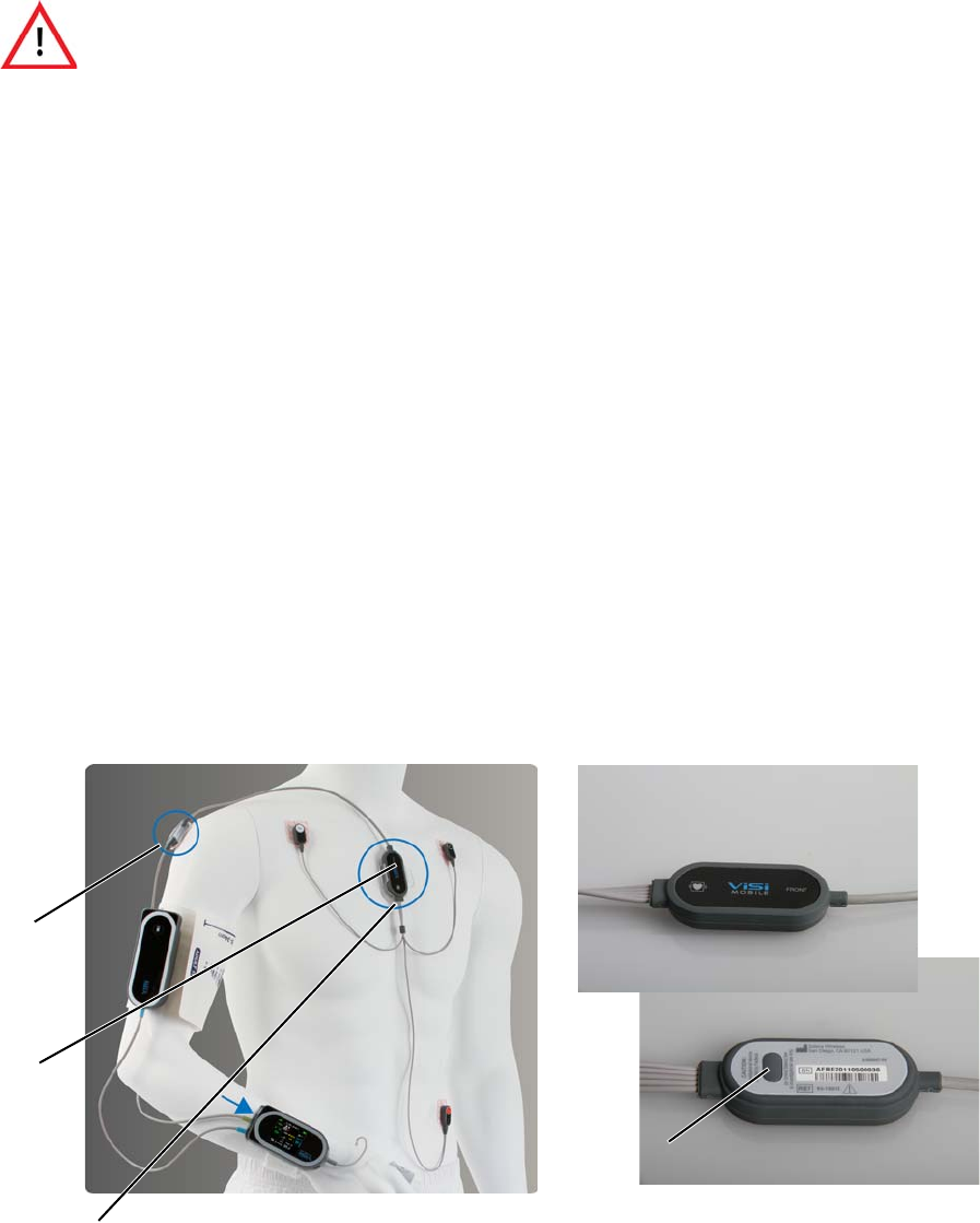
Applying ViSi Mobile Monitoring System / Initiate Monitoring
72
To apply the Chest Sensor
1. Remove the securements from the Disposable Kit and snap the Chest and Upper Arm Modules
into the securements.
2. Secure the Chest Module of the Chest Sensor between the sternum and the shoulder (same side as
the Monitor). The ideal location is the lower half of the sternum. If contraindicated, move the
Chest Module of the Chest Sensor higher on the sternum or laterally from the sternum.
Note: The Chest Sensor should be oriented vertically, with the lead wires hanging downward. Do
not orient the sensor more than a few degrees to the left or right.
Note: Ensure the “Front”, “ViSi Mobile” and “Defibrillation” labels on the Chest Module of the
Chest Sensor are facing outwards away from the patient’s skin.
Note: Ensure the “barcode” label and the Temperature sensor on the Chest Module of the Chest
Sensor are placed inwards directly against the patient’s skin.
Note: For patient comfort, shave or clip the hair in the areas where the Chest Module Securement
comes in contact with the chest.
3. Secure the Upper Arm Module of the Chest Sensor vertically on the outside of the upper arm.
4. Remove the ECG electrodes from the Disposable Kit.
5. Connect the Chest Sensor lead-wires to the ECG electrodes.
6. Apply the ECG electrodes to the prepared sites on the chest as shown.
Note: The default ECG configuration is Lead II.
Avoid placing the ViSi Mobile Cable Securements and ECG electrodes over
areas of abrasions, irritation, or other sensitive areas. If possible, remove,
reposition, and replace ECG electrodes and Cable Securements if the
patient complains of pain/itching at the sites.
Upper
Chest
Chest Sensor Module (rear view)
Chest Module (front view)
(Place this side against patient’s skin)
(Place this side away from the patient’s skin)
lead-wires
pointing downwards
Temperature Probe
Arm
Module
Sensor
Module
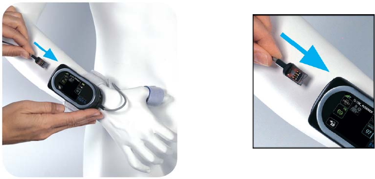
Applying ViSi Mobile Monitoring System / Initiate
73
7. Plug the Chest Sensor into any of the three ports on the flat end of the Monitor with the connector
contacts facing upwards.
Note: Monitoring of ECG, HR, RESP (optional), and TEMP starts automatically. Alarm limits are
set automatically according to predefined settings.
Note: Only attach one ViSi Mobile Chest Sensor to the patient and ViSi Mobile Monitor.
8. While palpating the pulse in the wrist of the arm opposite the Monitor, watch the beating heart
symbol at the top left of the HR numeric to ensure that it fluctuates with the patient’s heart beat.
The heart symbol beats with the pulse to confirm that the sensor is optimally placed. It may take
several seconds for the signal to stabilize.
• The indicated HR should match the palpated pulse rate. It may take several seconds for the
rate to stabilize on the Monitor.
• If the indicated HR is erratic or doesn’t match the palpated pulse rate, check to make sure
that the ECG electrodes and lead-wires are secure.
Note: In rare circumstances, the ECG electrodes may need to be placed in different locations to
improve the ECG signal.
9. While observing the patient, count the respiration rate and compare it to the RESP rate on the
Monitor. It may take several seconds for the signal to stabilize.
• The indicated RESP should match the observed rate.
• If the indicated RESP is erratic or doesn’t match the observed rate, check to make sure that
the ECG electrodes and lead-wires are secure.
Note: The Temperature sensor may take up to 6 minutes to reach a stable temperature reading.
Insert with connectors
contacts facing upwards
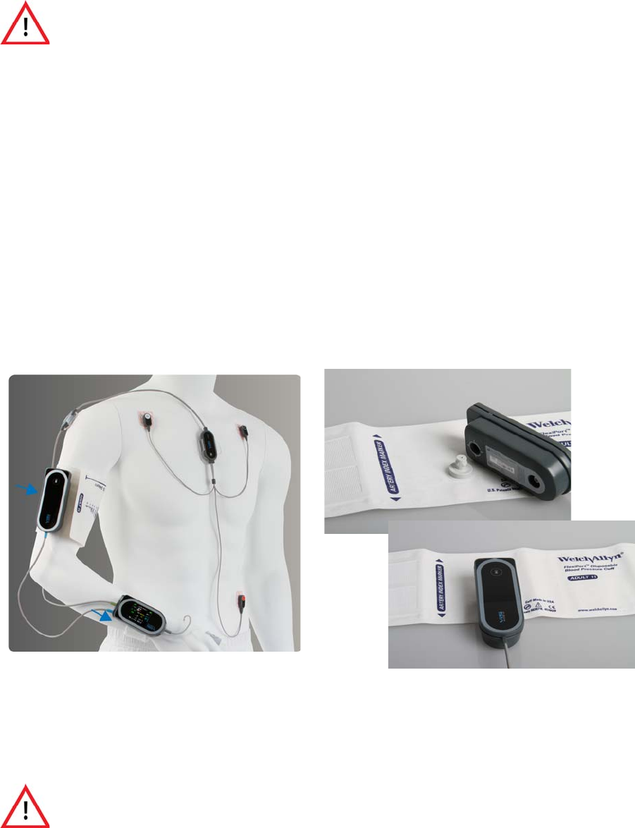
Applying ViSi Mobile Monitoring System / Initiate Monitoring
74
5.3.5 Applying the ViSi Mobile Cuff Module and Disposable Cuff
To apply the Cuff Module
1. Remove the Cuff from the Disposable Kit.
2. Squeeze as much air out of the Cuff as possible.
3. Ensure that the patient is resting so that the upper arm muscles are relaxed. The level of the middle
of the Cuff, while the arm is at rest, should be approximately at heart level.
4. Connect the Cuff Module securely to the Cuff.
5. Wrap the Cuff around the upper part of the same arm to which the Monitor is attached.
• Align the bottom part of the Cuff approximately 1” above the antecubital fossa.
• Align the artery marker on the Cuff with the brachial artery.
• The connector for the Cuff Module should be to the outside of the arm, away from the
body.
• The cable from the Cuff Module should be hanging down in the direction of the Monitor.
• Have the patient remain still to avoid the introduction of unnecessary motion artifact.
Note: The ViSi Mobile Disposable Cuff is designed to be used on the same arm with the other ViSi
Mobile sensors. It may temporarily cause the loss of function of other devices (not ViSi
Mobile) simultaneously used on the same limb.
Note: Only attach one ViSi Mobile Cuff Module to the ViSi Mobile Monitor..
ViSi Mobile Disposable Cuffs are for single patient use only. To avoid
possible cross contamination, do not reuse a Cuff on a patient other than the
original patient.
The ViSi Mobile Disposable Cuff should be snug enough to support the Cuff
Module while not impairing circulation when deflated.
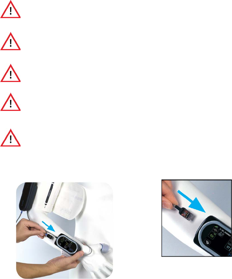
Applying ViSi Mobile Monitoring System / Initiate
75
6. Plug the Cuff Module into any of the open ports on the flat end of the Monitor with the connector
contacts facing upwards.
The NIBP Start button will be enabled, prompting you to start a Cuff inflation. See Taking a NIBP
Measurement on page 124 for instructions on how to take a NIBP measurement.
Avoid applying the ViSi Mobile Disposable Cuff over a wound as this can
cause further injury.
Avoid applying the ViSi Mobile Disposable Cuff on any limb where
intravascular access or therapy, or an arterio-venous (A-V) shunt, is present
because of temporary interference to blood flow which could result in injury
to the patient.
Take care in the application of the ViSi Mobile Disposable Cuff when
applying the Cuff to an arm on the same side of a mastectomy. Recommend
using the ViSi Mobile Monitoring System on the opposite arm.
ViSi Mobile blood pressure measurements (NIBP and cNIBP) have not been
clinically evaluated in the presence of atrial or ventricular arrhythmias. Use
alternative BP methods if these arrhythmias are present.
Inflate the ViSi Mobile Disposable Cuff only after proper application to the
patient’s limb.
Insert with connector
contacts facing upwards

Removing ViSi Mobile Monitoring System
76
5.4 Removing ViSi Mobile Monitoring System
Note: Before removing ALL the ViSi Mobile Monitoring System components, you should either
pause monitoring temporarily (see Pause Monitoring on page 139) or stop monitoring, if the
patient will no longer be monitored (see Stop Monitoring on page 142).
To remove Cuff and Cuff Module
1. Disconnect the Cuff Module from the Monitor: Grasp the Cuff Module cable near the plug and,
while holding the Monitor still, pull out the plug.
2. Unwrap the Cuff from the arm.
3. If the patient will no longer be monitored:
• Disconnect the Cuff Module from the Cuff.
• Dispose of the Cuff according to your facility’s policy.
To remove the Chest Sensor
1. Disconnect the Chest Sensor from the Monitor: Grasp the Chest Sensor cable near the plug and,
while holding the Monitor still, pull out the plug.
2. Remove the Cable Securements from the patient’s chest and arm and dispose of them according to
your facility’s policy.
3. To prevent placing stress on the lead-wires, grasp each lead-wire near the connection to the ECG
electrodes. Pull the lead-wires from the ECG electrodes.
4. Carefully remove the ECG electrodes from the patient and dispose of them according to your
facility’s policy.
To remove the Thumb Sensor
1. Disconnect the Thumb Sensor from the Monitor: Grasp the Thumb Sensor cable near the plug
and, while holding the Monitor still, pull out the plug.
2. Remove the Thumb Sensor from the patient.
3. Holding the ends of the Thumb Sensor between your thumb and index finger, gently bend the
Thumb Sensor backwards until it releases from the Thumb Wrap.
4. If the patient will no longer be monitored, dispose of the Thumb Wrap according to your facility’s
policy.
To remove the Wrist Cradle and Monitor
1. For ease of removal of the Wrist Cradle and Monitor, ensure all sensors are disconnected from the
Monitor.
2. Remove the Monitor from the Wrist Cradle.
3. Unwrap the Wrist Strap from the patient’s wrist and remove the Wrist Cradle from the patient’s
wrist.
All disposable components of the ViSi Mobile Monitoring System are for
single patient use only. To avoid possible cross contamination, do not reuse
any disposable items on a patient other than the original patient. Dispose of
the components and any packaging material after use per your facility’s
policy or national requirements.
Clinical Configurations
77
4. If the patient will no longer be monitored, dispose of the Wrist Cradle and Wrist Strap according to
your facility’s policy.
Clean the reusable components of the System: Monitor, Chest Sensor, Thumb Sensor, and Cuff Module, in
accordance with your facility’s procedures and the cleaning recommendations in this manual. See
Chapter 7. User/Preventative Maintenance on page 105.
5.5 Clinical Configurations
5.5.1 .XML File
The configuration options in the table below will configure the Monitor for the Facility’s Care Unit
through the .XML file that is stored on the server. Once the Monitor has connected to the network, the
clinical configurations will automatically be updated to the configurations set in the .XML file.
Note: Once the Monitor has connected to the network, any other configurations that were
previoulsy set using, including while in Bio Med Mode, will be over-written.

Clinical Configurations
78
5.5.2 Units of Measure
5.5.3 Monitor Timeout
The Clinical screen on the Wrist Monitor will timeout after a specified period of inactivity.
a. The Wrist Monitor screen can be set to timeout at different intervals and the user will be
required to authenticate before viewing the screen again.
b. When “Off” has been selected, the screen will never timeout; a user will not be required to
authenticate to view the screen again.
5.5.4 Clinical Authentication
The Clinical Authentication option determines if a user must authenticate using a 4-digit PIN before
accessing the Monitor features.
a. When “On” has been selected, the user will be prompted to authenticate using a 4-digit PIN
before being able to access the clinical screens.
Configuration Options Option Values Level Updateable
Blood Pressure mmHg (default)
kPa
Facility: yes
Care Unit: no
Temperature Fahrenheit (oF) (default)
Centigrade (oC)
Facility: yes
Care Unit: no
Date Display Format Mon DD, YYYY(default)
DD Mon YYYY
MM/DD/YYYY
DD/MM/YYYY
Facility: yes
Care Unit: no
Time Display Format 12 hr (default)
24 hr
Facility: yes
Care Unit: no
ECG Line Noise Filter 50 Hz
60Hz (default)
Facility: yes
Care Unit: no
Configuration Options Option Values Level Updateable
Monitor Timeout 15 Seconds
30 Seconds
1 Minute
3 Minutes (default)
Off
Facility: yes
Care Unit: no
Monitor: no
Configuration Options Option Values Level Updateable
Clinical Authentication On (default)
Off
Facility: yes
Care Unit: yes
Monitor: yes
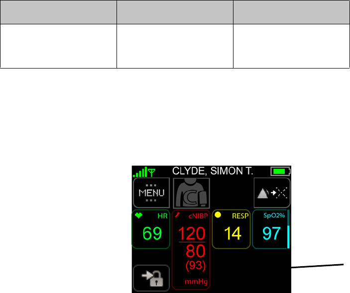
Clinical Configurations
79
b. When “Off” has been selected, the user will have full access to the clinical screens without
having to authenticate with a 4-digit PIN before accessing.
5.5.5 Skin Temperature Configuration
The Skin Temperature Configuration is an available option to turn “On” or “Off” within the
Facility’s Care Unit. This option cannot be changed on a per Monitor basis on a netoworked
floor.If Skin Temperature is turned “On” for the Facility’s Care Unit through the network, then all
networked Monitors’ configurations will be synched to the .XML file once the Monitor connects to the
network again.
Note: Only while in Bio Med Mode is it possible to turn the Skin Temperature vital sign “On” or
“Off.”
Note: Un-Networked/Standalone Monitors are the only Monitors that are able to have Skin
Temperature turned “On” or “Off” while in Bio Med Mode.
a. When “On” is selected for Skin Temperature and the Chest Sensor is connected to the Wrist
Monitor, the Skin Temperature vital sign measurement will be displayed.
b. When ”Off” is selected for Skin Temperature and the Chest Sensor is connected to the Wrist
Monitor, the Skin Temperature vital sign will not be displayed.
Configuration Options Option Values Level Updateable
Skin Temperature On (default)
Off
Facility: yes
Care Unit: yes
Monitor: yes
Skin TEMP OFF
Clinical Configurations
80

81
6. Alarms
6.1 Introduction
The ViSi Mobile Monitoring System provides a comprehensive alarm system that alarms on changes to the
patient’s physiologic status (alarms) and technical alarms (alerts).
The system provides default alarm limits for physiological alarms. The clinician can manually manage the
alarm limits for each patient to provide individualized care.
Technical alarms (alerts) are provided to notify the clinician of situations that may impede the ability to
monitor your patient.
6.1.1 System Alarm Management
During the installation of the ViSi Mobile Monitoring System, alarm configurations may be modified to
conform to the alarm policies set by the clinical care unit.
General Alarm Management Rules
The following general alarm management rules pertain to the ViSi Mobile Monitoring System:
• All ViSi Mobile Monitoring System alarms conform to IEC 60601-1-8.
• Alarms and alerts originate from the ViSi Mobile Monitor (worn by the patient).
• Silencing/acknowledging a patient’s alarm or alert suspends the audio tones for up to 2 minutes.
When a new alarm/alert occurs during the 2 minute silenced/acknowledged period, the new alarm/
alert will be immediately annunciated.
Note: When the clinician silences/acknowledges an alarm/alert, all active alarms/alerts in progress
will also be silenced/acknowledged for the 2 minutes. The clinician does not need to silence/
acknowledge each alarm/alert individually.
• Alarm annunciation may be turned off for an indefinite period of time. This disables the
annunciation of alarms and alerts on both the ViSi Mobile Monitor and the Remote Viewer for the
“off” duration. Turning the alarms off must be done directly from the ViSi Mobile Monitor (worn
by the patient), however, alarms may be turned back on from either the ViSi Mobile Monitor or the
Remote Viewer.
• Alarm annunciation may be paused for 2 minutes. This disables the annunciation of alarms and
alerts on both the ViSi Mobile Monitor (worn by the patient) and the Remote Viewer for the
paused duration. Pausing the alarms must be done directly from the ViSi Mobile Monitor (worn by
Introduction
82
the patient), however, alarms may be resumed from either the ViSi Mobile Monitor or the Remote
Viewer.
Note: When the annunciation of alarms/alerts has been turned off or paused, certain important
alarms and alerts will continue to annunciate (known as break-through alarms and alerts).
These are generally equipment alerts that inhibit the ability to monitor the patient
appropriately.
Note: When alarms/alerts are paused, alarms/alerts currently in progress will no longer be
annunciated. The annunciation of any new alarms/alerts will be disabled for the 2 minute
duration.
Note: When alarms/alerts are silenced/acknowledged, the audio tone will be silenced. Any new
alarms/alerts occurring during the 2 minute silenced/acknowledged duration will be
immediately annunciated.
In Network Rules
When the ViSi Mobile Monitor is in network and connected to the ViSi Mobile Remote Viewer:
• When the ViSi Mobile Monitor is connected to the Remote Viewer, the audio alarm and alert tones
will be deferred from the Monitor to the Remote Viewer, for a pre-configured length of time.
Note: Audio tones for life threatening alarms will not be delayed.
• Alarms/alerts may be silenced/acknowledged from either the ViSi Mobile Monitor or Remote
Viewer.
Note: Silencing/acknowledging a life threatening alarm directly from the ViSi Mobile Remote
Viewer will only silence/acknowledge the alarm on the Remote Viewer. To silence/
acknowledge the life threatening alarm on the ViSi Mobile Monitor, the clinician must
silence/acknowledge the alarm directly from the Mobile Monitor (worn by the patient).
• When alarm annunciation has been turned off, alarm annunciation may be turned back on from
either the ViSi Mobile Monitor or Remote Viewer. Turning alarm annunciation off can only be
done directly from the ViSi Mobile Monitor (worn by the patient).
• When alarm annunciation has been temporarily paused, alarm annunciation may be resumed from
either the ViSi Mobile Monitor or Remote Viewer. Pausing alarm annunciation can only be done
directly from the ViSi Mobile Monitor (worn by the patient).
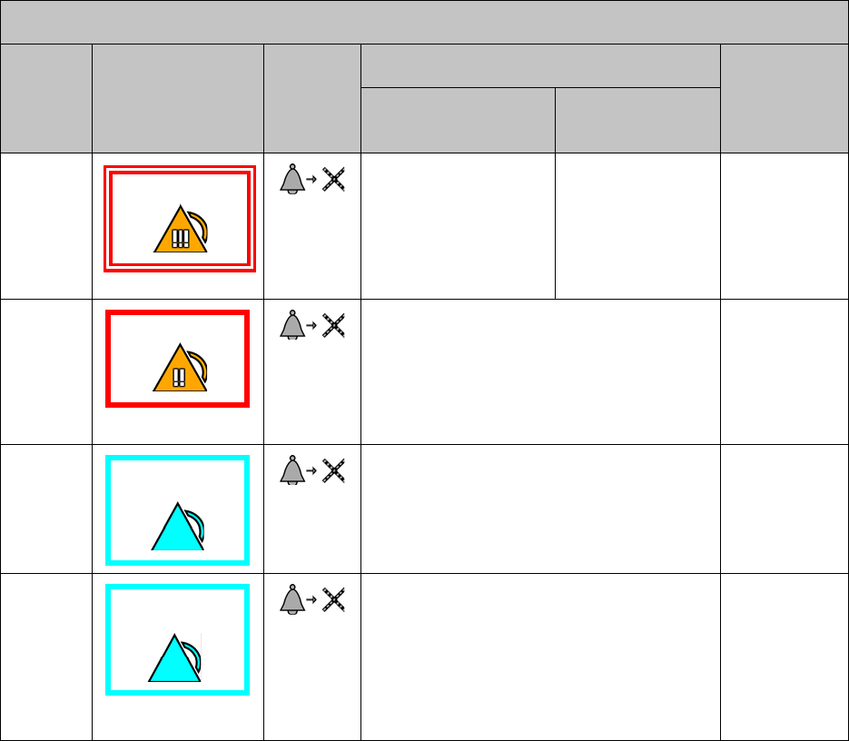
Physiological Alarms (Alarms) / Technical Alarms
83
6.2 Physiological Alarms (Alarms) / Technical Alarms
(Alerts) Summary
6.2.1 Responding to Alarms/Alerts
Silencing Audible Alarms/Alerts from ViSi Mobile Remote Viewer
Priority Type of Alarm Silence
Button
Where to Respond to Alarm
Audio Tonesa
a. Audio tones associated with alarms/alerts will only occur on the ViSi Mobile Monitor when the Monitor
is not connected to a known network. Audio tones will always occur on the ViSI Mobile Remote
Viewer.
Remote Viewer
(At Clinician’s Station) Mobile Monitor
(At Patient)
1 Silenced at the Remote
Viewer for 2 minutes.
Continues on Mobile
Monitor
Audible continues
on Mobile Monitor
until silenced on
Mobile Monitor.
Beep
Beep
Beep
- Pause -
Beep
Beep
2 Silence at Remote Viewer or Mobile Monitor.
(2 minute audible silenced on both Remote
Viewer and Mobile Monitor.)
Beep
Beep
Beep
- Pause -
Beep
Beep
3 Silence at Remote Viewer or Mobile Monitor.
(2 minute audible silenced on both Remote
Viewer and Mobile Monitor.)
Beep
Beep
- Pause -
4 Visual Only - No Sound
Acknowledge at the Remote Viewer or Mobile
Monitor.
(Acknowledged for 2 minutes at both the
Remote Viewer and Mobile Monitor.)
No audio
tones.
Life Threatening
High
(High)
Alerts
(Low)
Alerts

Physiological Alarms (Alarms) / Technical Alarms (Alerts) Summary
84
6.2.2 Managing Alarm/Alert Annunciations
Annunciation: Refers to the audible and visual display of alarms/alerts.
Note: When multiple alarms and alerts occur simultaneously, the message text will display
messages associated with only the highest alarm severity. The vital signs measurements will
display all existing alarms, regardless of their severity.
Action Action Button Duration Allow Where Effects
Pause Alarms/
Alerts
N/A 2 Minutes May only be paused
from the ViSi Mobile
Monitor.
Annunciation disabled at
both the ViSi Monitor and
Remote Viewer.
Resume Alarms/
Alerts
N/A ViSi Mobile Monitor and
Remote Viewer.
Annunciation resumed at
both the ViSi Mobile
Monitor and Remote
Viewer.
Turn Alarms/
Alerts Off
N/A Indefinitely May only be turned off
from the ViSi Mobile
Monitor.
Annunciation disabled at
both the ViSi Monitor and
Remote Viewer.
Turn Alarms/
Alerts On
N/A ViSi Mobile Monitor and
Remote Viewer.
Annunciation turned on at
both the ViSi Mobile
Monitor and Remote
Viewer.
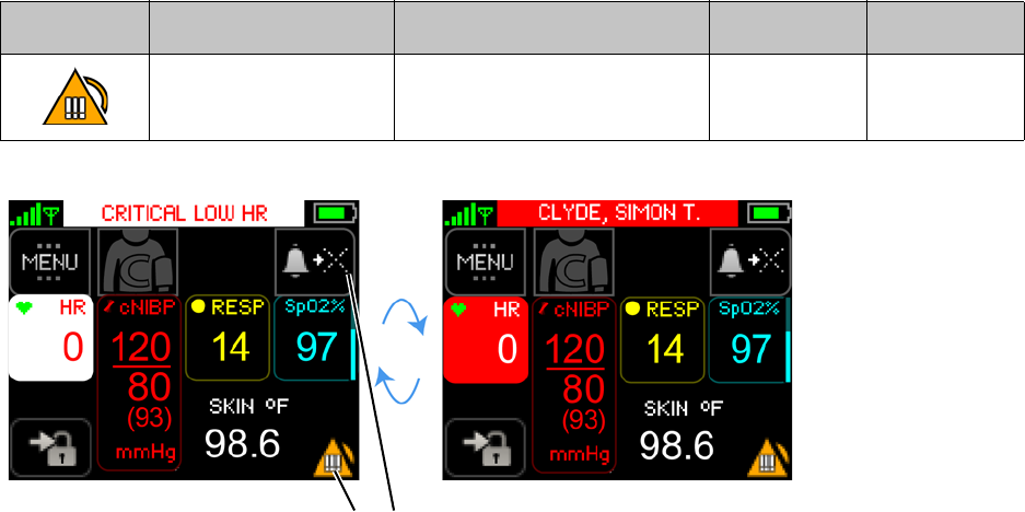
Responding to Physiological Alarms (Alarms)
85
6.3 Responding to Physiological Alarms (Alarms)
6.3.1 To Silence/Acknowledge Life Threatening Severity Alarms
Life threatening severity alarms require urgent clinician response at the bedside.
Symbol Annunciation Color Audio Tone Duration (ms) Spacing (ms)
White / Red BBB P BB P BBB P BB...
B - Beep / P - Pause
100 50
Silence/Acknowledge
Alarm
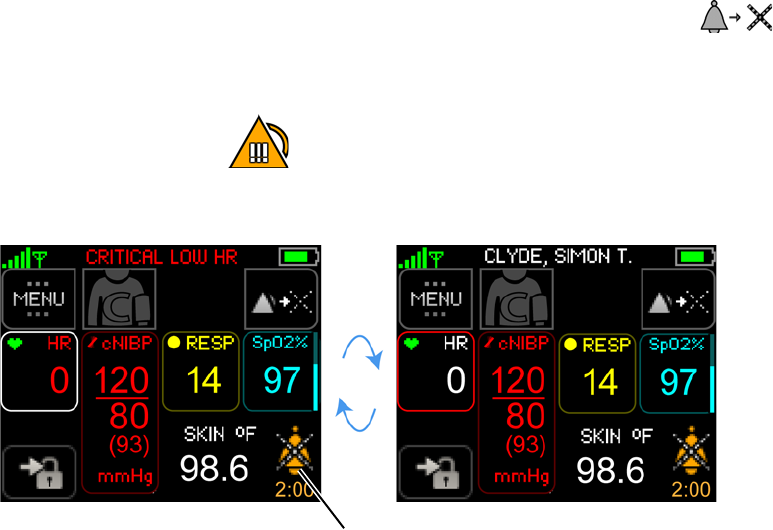
Responding to Physiological Alarms (Alarms)
86
To silence/acknowledge the alarm, touch Silence/Acknowledge Alarm button
- or -
Touch the Alarm Status.
The alarm is silenced/acknowledged and the “Silenced/Acknowledged” symbol and countdown
appear. After the 2 minute countdown expires, the alarm is re-annunciated.
Note: When a Life Threatening alarm occurs and the alarming condition resolves itself before a
clinician is able to respond, visual and audio indications of the life threatening alarm
continue to annunciate until the clinician silences the alarm.
Silenced/Acknowledged
symbol and countdown
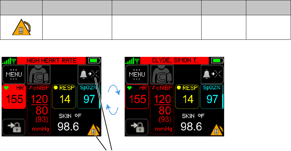
Responding to Physiological Alarms (Alarms)
87
6.3.2 To Silence High Severity Alarms
High severity alarms require immediate clinician response at the bedside.
Symbol Annunciation Color Audio Tone Duration (ms) Spacing (ms)
Red BBB P BB P BBB P BB...
B - Beep / P - Pause
200 100
Silence/Acknowledge
Alarm
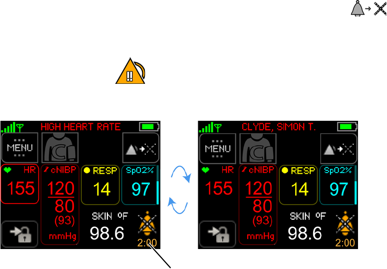
Responding to Physiological Alarms (Alarms)
88
To silence/acknowledge the alarm, touch Silence/Acknowledge Alarm button
- or -
Touch the Alarm Status.
The alarm is silenced/acknowledged and the silenced/acknowledged symbol and countdown
appear.
Note: When a high alarm occurs and the alarming condition resolves itself before a clinician is able
to respond, the high alarm message appears (in gray) for up to 5 minutes in the message
area. This serves as a reminder to the clinician that a high alarm has occurred.
Silenced/Acknowledged
symbol and countdown
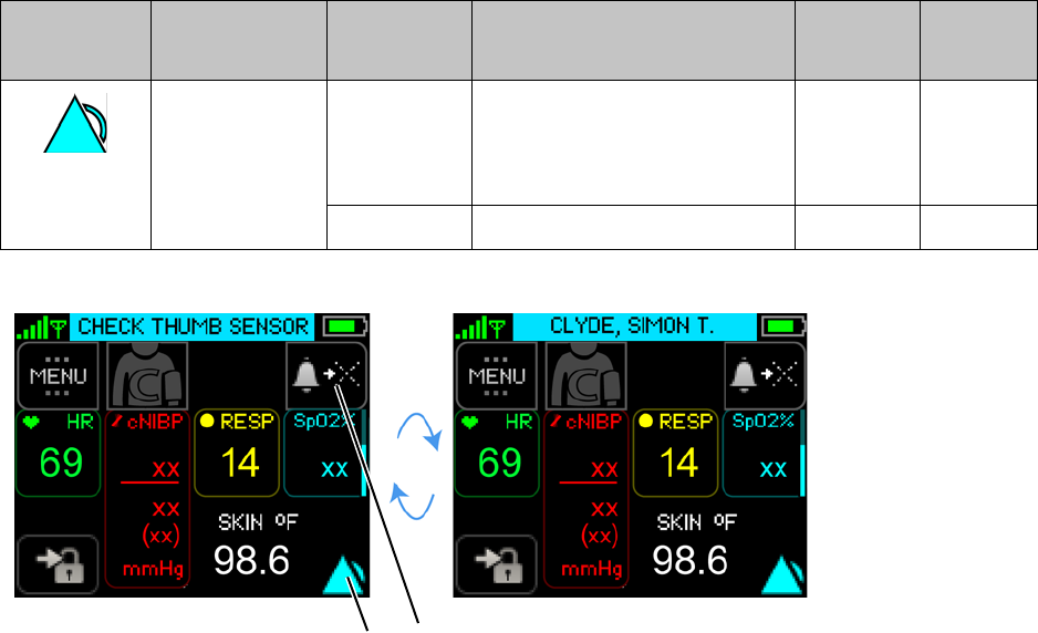
Responding to Equipment Alarms (Alerts)
89
6.4 Responding to Equipment Alarms (Alerts)
6.4.1 To Silence/Acknowledge Alerts (All Severities)
Equipment alerts are used when the ability to monitor the patient and detect a patient’s physiological
alarms may be affected.
Symbol Annunciation
Color Severity Audio Tone Duration
(ms) Spacing
(ms)
Cyan High B B P
B - Beep / P - Pause
There will be a 15 second pause
after each sequence.
250 250
Low No audio tones. N/A N/A
Silence/Acknowledge
Alarm
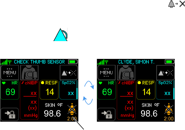
Responding to Equipment Alarms (Alerts)
90
To silence/acknowledge the alert, touch Silence/Acknowledge Alarm button
- or -
Touch the Alert Status.
The alert is silenced/acknowledged and the silenced/acknowledged symbol and countdown will be
displayed.
Note: When an alert condition (of any severity) resolves itself before the clinician is able to
respond, the alert condition will no longer be annunciated.
Silenced/Acknowledged
symbol and countdown
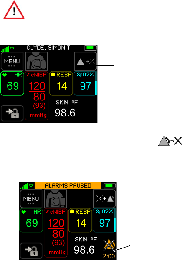
Managing Alarm Annunciations
91
6.5 Managing Alarm Annunciations
6.5.1 Pause / Resume Alarms
To pause the alarms
From the Vital Signs screen, touch Pause Alarms.
The alarms will be paused for 2 minutes.
When paused, the words ALARMS PAUSED appear at the top of the screen and an ALARMS
PAUSED icon appears in the lower right corner of the screen.
Note: When the clinician logs out of the ViSi Mobile Monitor, the alarms will automatically be
resumed.
When alarms are paused, there is no notification of a potentially clinically
significant change in the patient's vital signs. Observe the patient by other
means when alarms are paused.
Pause Alarms
Alarms are paused
Remaining “Paused” duration
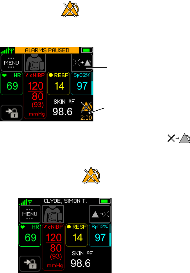
Managing Alarm Annunciations
92
To Resume Alarms
When alarms are paused, the annunciation of any existing and new alarm will be disabled at both the ViSi
Mobile Monitor and Remote Viewer. Alarms may be resumed from either the Mobile Monitor or Remote
Viewer.
To resume alarm annunciation, touch the Resume button.
- or -
Touch the AlarmStatus.
The alarms resume and annunciate at both the ViSi Mobile Monitor and Remote Viewer.
Alarms are currently paused.
Remaining “Paused” duration.
Resume alarms
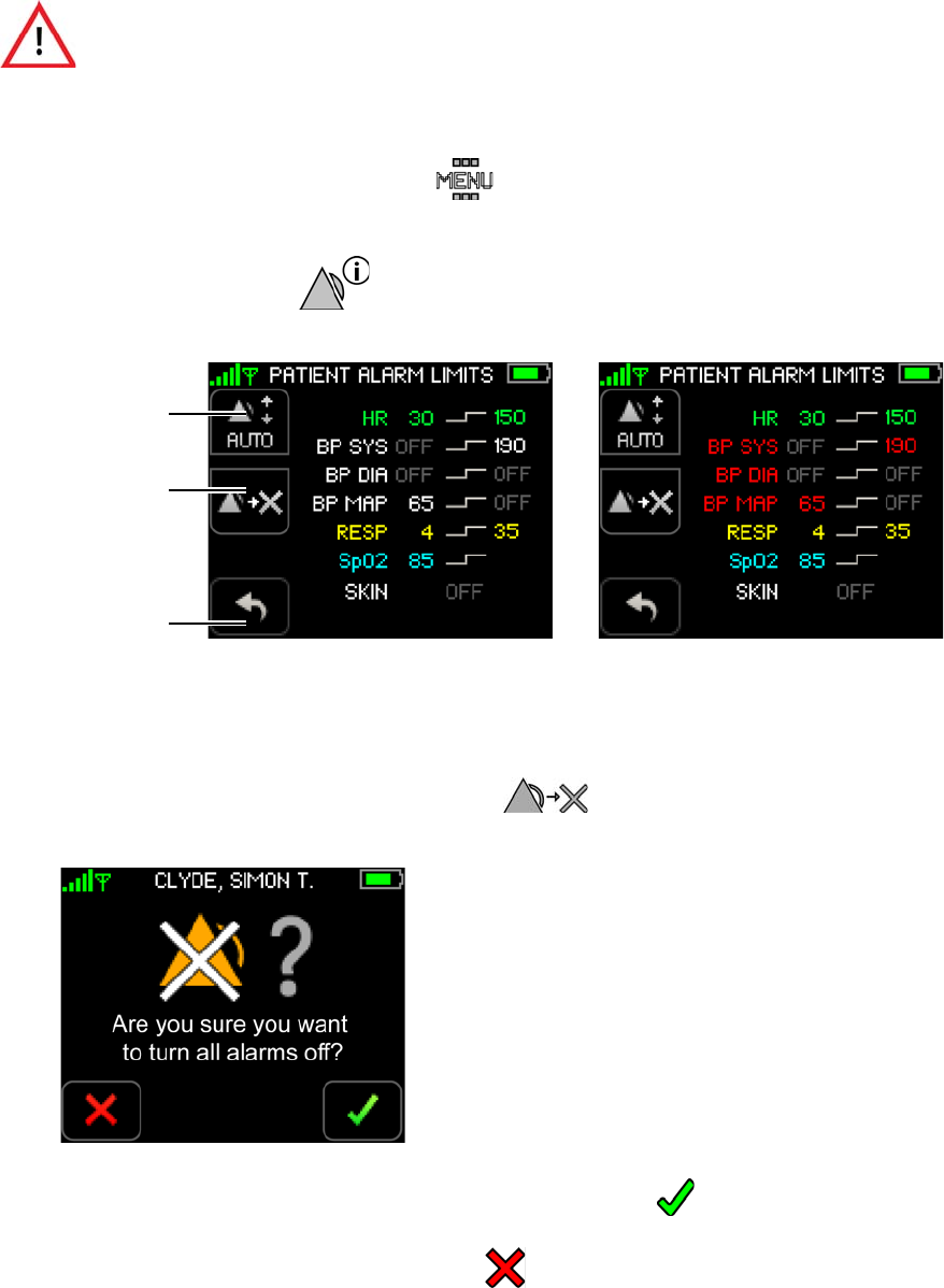
Managing Alarm Annunciations
93
6.5.2 Turn Alarm Annunciation On / Off
To turn all alarms off
1. Touch Menu on the Vital Signs screen.
The Menu screen appears.
2. Touch Alarms Settings.
The Patient Alarm Limits screen appears. Alarm limit settings appear for the connected sensors.
Note: Systolic, diastolic and MAP alarm limits for cNIBP appear in red when measuring NIBP
continuously. Normal NIBP alarm limits appear in white.
3. To turn all alarms off, touch Turn Alarms Off.
The Turn Alarms Off confirmation screen appears.
4. Touch Confirm to confirm that you want to turn all alarms off.
-or-
Touch Cancel to leave the alarms turned on.
When alarms are turned OFF, there is no notification of a potentially
clinically significant change in the patient's vital signs. Observe the patient
by other means when alarm limits are set to OFF.
Turn Alarms Off
Auto Set
Return to
Previous Screen NIBP Alarm Limits cNIBP Alarm Limits
(Alarm limits in white) (Alarm limits in red)
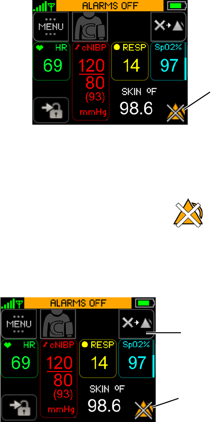
Managing Alarm Annunciations
94
If cancelled, the system returns to the Patient Alarm Limits screen and the alarms remain turned
on.
If confirmed, the alarms are turned off and the Vital Signs screen appears. The words ALARMS
OFF appear at the top of the screen and an ALARMS OFF icon appears in the lower right corner
of the screen.
Note: Alerts that indicate the Monitor is unable to measure a vital sign (such as ECG Lead Fail)
can not be turned off.
To Turn On Alarm Annunciation
When alarms are turned off, the annunciation of any existing and new alarm will be disabled at both the
ViSi Mobile Monitor and Remote Viewer. Alarms may be turned back on directly from the Monitor and
Remote Viewer.
ALARMS OFF Icon
(flashes on/off)
Alarms are currently
Turn alarms
turned off
back on
(flashes on/off)
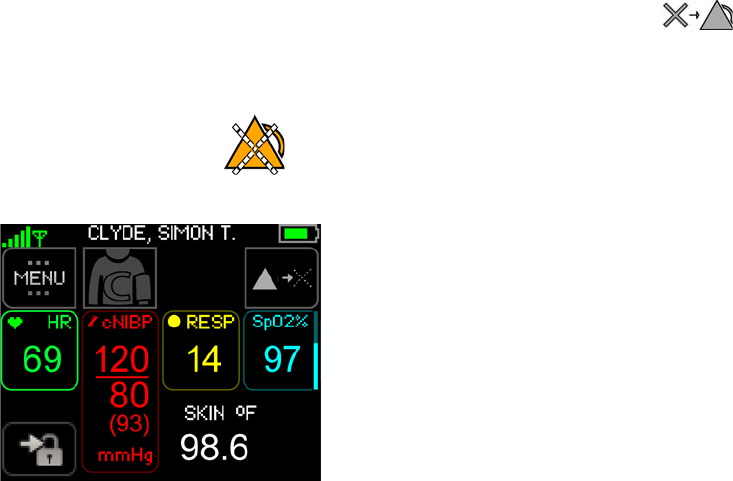
Managing Alarm Annunciations
95
To turn the alarm annunciation back on, touch the Turn Alarms On button.
- or -
Touch the Alarm Status.
The alarms will be turned back on.
Note: Alarm annunciation will be turned on at both the ViSi Mobile Monitor and Remote Viewer.
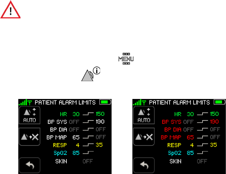
Manage Alarm Limits
96
6.6 Manage Alarm Limits
Alarm limits for each vital sign parameter are predefined and turned on automatically when sensors are
connected to the patient and to the Monitor. Sometimes it is desirable to adjust the alarm limits to meet a
patient’s monitoring requirements.
The Auto Set function only sets alarm limits for vital sign measurements that are currently in alarm. The
new alarm limits are based on the current vital signs measurements.
To change alarm limits using Auto Set
1. Touch Menu on the Vital Signs screen.
2. Touch Alarms Settings.
The Patient Alarms Settings screen appears.
Note: Systolic, diastolic and MAP alarm limits for cNIBP appear in red when measuring NIBP
continuously. Normal NIBP alarm limits appear in white.
Note: Alarm limit settings appear only for the currently monitored vital signs.
Once Auto Set is selected (on the ViSi Mobile Monitor), review the newly
calculated alarm limits carefully before deciding to confirm or cancel the new
alarm limits. Once new alarm limits are confirmed on the ViSi Mobile
Monitor, they cannot be changed back to the original pre-set limits from the
ViSi Mobile Monitor. Use the ViSi Mobile Remote Viewing Device to change
the alarm limits back to the original pre-set limits.
NIBP Alarm Limits cNIBP Alarm Limits
(Alarm limits in white) (Alarm limits in red)
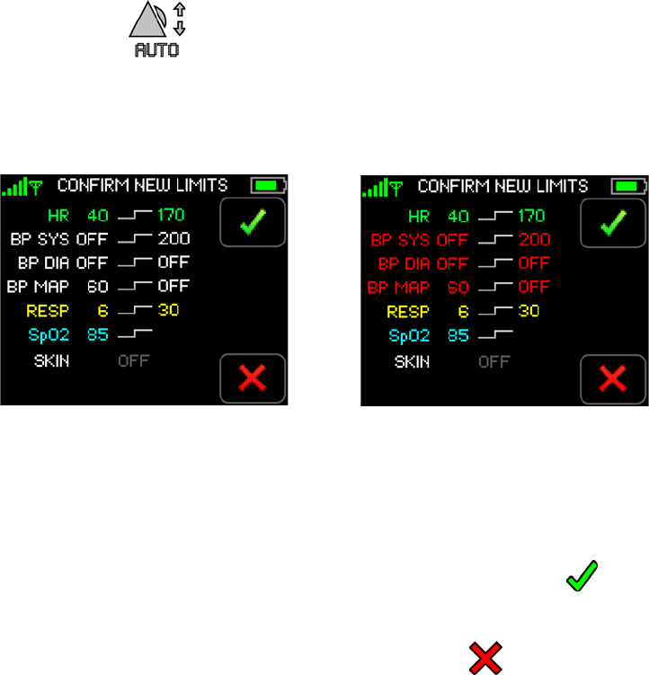
Manage Alarm Limits
97
3. Touch Auto Set.
The Confirm New Alarm Limits screen appears.
Alarm limits for all vital sign measurements currently in alarm are recalculated based on the
current vital signs measurements.
Note: Systolic, diastolic and MAP alarm limits for cNIBP appear in red when measuring NIBP
continuously. Normal NIBP alarm limits appear in white.
Note: Upper and lower alarm limits cannot be set for TEMP.
4. Touch Confirm to confirm that you want to accept the new alarm limits.
-or-
Touch Cancel to return to the Patient Alarm Limits screen.
The previous alarm limits are retained.
Once confirmed, the system returns to the Vital Signs screen.
5. Navigate to the Patient Alarm Limits screen to review the current alarm limits.
NIBP Alarm Limits cNIBP Alarm Limits
(Alarm limits in white) (Alarm limits in red)

Manage Alarm Limits
98
When selecting Auto Set, alarm limits are calculated to clinically relevant values based on the patient’s
present condition. Auto Set is not available for temperature. The minimum and maximum values to which
auto set will adjust the limits are listed in the table below.
Note: Individual alarm limits may only be manually set from the ViSi Mobile Remote Viewer and
not from the ViSi Mobile Monitor. Auto Set recalculates all alarm limits for vital sign
measurements currently in alarm.
Auto Set Alarm Limits
Alarm Limit Default
Limits Auto Set
Range Auto Set Limit Calculation
(based on current reading)
Heart Rate (BPM) High 140 90-200 HR x .75 + 50
Low 40 30-80 HR x .545 + 13.636
Pulse Rate (BPM) High 140 90-160 PR x 0.66 + 53.3 .75 + 50
Low 40 30-80 PR x 0.54 + 13.6 .545 + 13.636
BP Systolic (mmHg) High 190 160-240 BP x 0.75 + 60.0
Low OFF 60-120 BP x 0.71 + 17.1
BP Diastolic (mmHg) High OFF 95-150 BP x 0.60 + 60.0
Low OFF 30-90 BP x 0.72 + 8.3
BP MAP (mmHg)a
a. There is no autoset associated with BP MAP vital sign measurements.
High OFF N/A .66 + 60.0
Low 65 N/A .718 + 11.838
Respiration (BR/M) High 35 12-40 RR x 0.69 + 12.5
Low 6 5-8 RR x 0.28 + 3.6
SpO2 (%) Low 85 85-90 SpO2 less than 87, limit set to 85
SpO2 between 87 and 90, limit set to SpO2 - 2%
SpO2 between 90 and 95, limit set to SpO2 - 3%
SpO2 greater than 95, limit set to 90
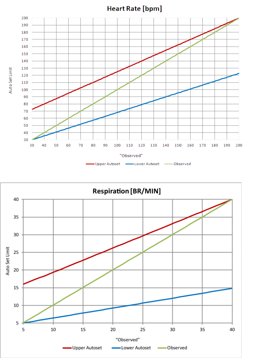
Manage Alarm Limits
99
Auto Set Alarm Limits
(Heart Rate / Respiration)
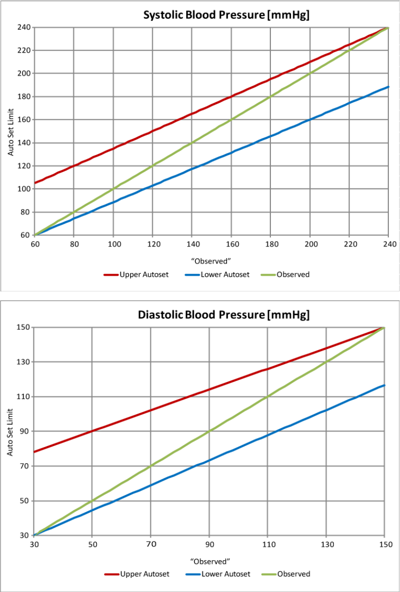
Manage Alarm Limits
100
Auto Set Alarm Limits
(Blood Pressure)
Manage Alarm Limits
101
6.6.1 Testing Alarms
Whenever a sensor is connected to the Monitor, a self-test of that sensor is initiated automatically to verify
the sensor is in good working order. If the sensor and Monitor speaker are in good working order, you will
hear a double beep.
Do not cover the microphone of the Monitor during the self-test
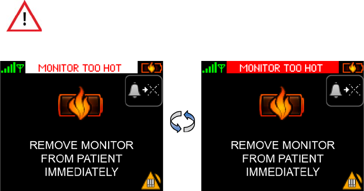
Battery Too Hot Alarms
102
6.7 Battery Too Hot Alarms
6.7.1 Monitor Too Hot
The Monitor Too Hot alarm annunciates when one of the following occurs:
• The battery in the ViSi Mobile Monitor exceeds the defined safety limits.
• The temperature sensor in the ViSi Mobile Chest Sensor exceeds the defined safety limits.
• The current between the ViSi Mobile Monitor and the Chest Sensor exceeds an 80 second average
of 250mA.
Remove the ViSi Mobile Monitor and Chest Sensor from the patient immediately and allow the
components to cool down. Do not put the Monitor into the Battery Charger until it has cooled down.
Return the Monitor and Chest Sensor to Sotera Wireless, Inc.
Note: If the battery in the ViSi Mobile Monitor exceeds the defined safety limits while it is in the
Charger, remove the Monitor from the Charger and allow the Monitor to cool down.
When the “Monitor Too Hot” alarm is in progress, the ViSi Mobile Monitor
and Chest Sensor should be removed from the patient immediately. Leaving
them on the patient for an extended period of time may lead to a skin burn.
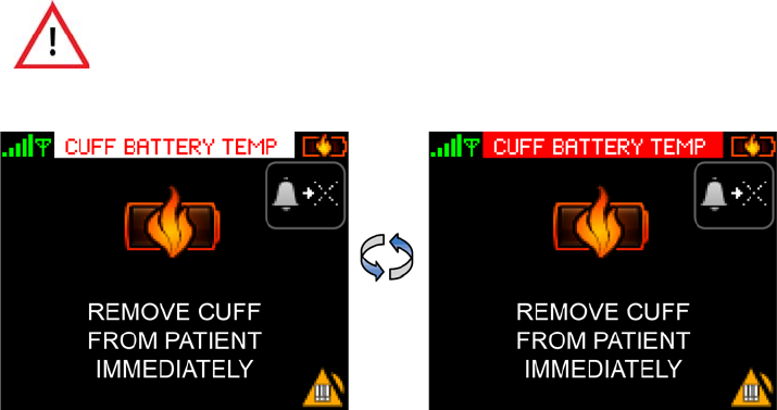
Battery Too Hot Alarms
103
6.7.2 Cuff Module Battery Temp (Cuff Too Hot)
The Cuff Battery Temp alarm annunciates when the battery in the ViSi Mobile Cuff Module exceeds the
defined safety limits.
Remove the ViSi Mobile Cuff Module from the patient immediately and allow it to cool down. Do not put
the Cuff Module into the Battery Charger until it has cooled down.
Return the Cuff Module to Sotera Wireless, Inc.
Note: If the battery in the ViSi Mobile Cuff Module exceeds the defined safety limits while it is in
the Charger, remove the Cuff Module from the Charger and allow the Cuff Module to cool
down.
When the “Cuff Battery Temp” alarm is in progress, the ViSi Mobile Cuff
Module should be removed from the patient immediately. Leaving it on the
patient for an extended period of time may lead to a skin burn.
Battery Too Hot Alarms
104
- Notes -

105
7. User/Preventative Maintenance
7.1 Introduction
This section of the manual outlines routine maintenance that should be performed by the user. The ViSi
Mobile Monitoring System is designed for stable operation over long periods of time and, under normal
circumstances, should not require technical maintenance beyond that described in this section.
7.2 Preventative Maintenance
All ViSi Mobile components are designed to internally calibrate each time they are used. Therefore, no
routine calibration checks are required during routine preventative maintenance cycles. Routine testing of
functionality/accuracy can be verified using standard electronic patient simulators and compared against
the references in this manual.
Sotera Wireless, Inc. recommends preventative maintenance as follows:
Note: Prior to any preventative or corrective service, ViSi Mobile components should be cleaned
and disinfected. See below.
In the event any component needs to be returned to Sotera Wireless, Inc; contact the Sotera Wireless, Inc.
Customer Service Department or the Sotera Wireless, Inc. representative in your area. Prior to shipping,
ensure the returned components have been properly disinfected.
Chest Sensor /
Monitor
Visual inspections for mechanical abuse is recommended at a frequency consistent with
use. Annual inspection is recommended but not required.
Cuff Module Visual inspection and routine calibration checks against a known volume is
recommended on an annual basis. The air filter should be replaced at this time.
Calibration volume and replacement air filters can be purchased from Sotera Wireless,
Inc. or the units can be returned to Sotera for a nominal fee.
SpO2 Sensor The SpO2 sensor comes with a standard 3 month warranty. Actual life cycle duration is
dependent on use and care. No preventative maintenance is required.
Optional ViSi Power
Pack
Regular visual inspection for mechanical abuse is recommended at a frequency
consistent with use. The ViSi Power Pack does not require calibration.
The ViSi Mobile Monitoring System components, including the ViSi Power
Pack should only be serviced by Sotera Wireless, Inc. technicians or
authorized service providers.

Cleaning and Disinfection
106
7.3 Cleaning and Disinfection
The ViSi Mobile Monitor, Cuff Module, Chest Sensor, Thumb Sensor, and Power Pack require cleaning
and disinfection prior to reuse on a different patient. To prevent possible cross-contamination, properly
clean and/or disinfect all ViSi Mobile reusable components between patients.
If the ViSi Power Pack beeper/buzzer sounds or the Red LED is
permanently lit, the ViSi Power Pack should be disconnected from the
patient immediately.
Do not clean the ViSi Mobile Monitor, Cuff Module, Chest Sensor, Thumb
Sensor, or ViSi Power Pack with detergents while worn by the patient.
Do not clean the ViSi Mobile Monitor, the Cuff Module, or the Power Pack
while it is plugged into the ViSi Mobile Charger.
Do not apply liquid to the ViSi Mobile Cuff Module or the Power Pack. To
clean, use a damp cloth.
Ensure the sensor connector contacts are thoroughly dried to prevent
possible malfunction.
Thumb sensors which are saturated with liquid should be allowed to air dry
thoroughly before re-use.
Do not use bleach, abrasive cleaning agents or organic solvents on any of
the ViSi Mobile Monitoring System components.
Use only recommended clenaing/disinfecting agents to prevent damage to
the device and components. See page 107.
Do not autoclave the ViSi Mobile Monitor, its components, or accessories.
Do not use excessive amounts of liquid when cleaning the ViSi Mobile
Chest Sensor or Thumb Sensor.
Cleaning and Disinfection
107
Prior to cleaning and disinfecting:
1. Pre-clean at the point of use to remove and prevent drying of soil and contaminants.
2. Ensure all components are disconnected, including the ViSi Mobile Monitor from the Wrist Cradle
and the Thumb Sensor from the Thumb Wrap.
3. When cleaning the optional ViSi Power Pack, first remove the Power Pack from the Power Pack
Cradle. All components of the ViSi Power Pack should be cleaned and disinfected between uses.
Recommended cleaning/disinfection agents. Use either of the following:
1. Clean with soap or detergent followed by disinfection with 70% isoprophyl alcohol.
2. Clean and disinfect with Super Sani-Cloth® Germicidal Disposable Wipes.

Cleaning and Disinfection
108
To clean the ViSi Mobile Monitoring System components
1. Hand-wash the System components using mild soap or detergent (e.g. Alconox) and water.
Do not appy liqiud to the Cuff Module or Power Pack, instead use a damp cloth.
2. A soft-bristled brush may be used for heavily soiled areas, as needed.
3. Dry thoroughly using a soft cloth or paper towel.
4. Visually examine the reusable components to ensure all soil contaminants have been removed.
5. Repeat the above cleaning process as required.
Note: Use a new Super Sani-Cloth®; disinfect according to manufacturer’s recommended
procedure.
To disinfect the ViSi Mobile Monitoring System components
To disinfect the ViSi Mobile Monitoring System components:
1. Disinfect the reusable components by wiping with a Super Sani-Cloth® (purple top) or use a basic
wipe moistened with 70% isopropyl alcohol.
2. Dry thoroughly using a soft cloth or paper towel.
Note: Use a new Super Sani-Cloth®; disinfect according to manufacturer’s recommended
procedure.
Do not use bleach, abrasive cleaning agents or organic solvents on any of
the ViSi Mobile Monitoring System components.
Do not autoclave the ViSi Mobile Monitor, its components, or accessories.
Do not use excessive amounts of liquid when cleaning the ViSi Mobile Chest
Sensor CableChest Sensor or the ViSi Mobile Thumb Sensor.
Inspecting Equipment and Accessories
109
7.4 Inspecting Equipment and Accessories
After cleaning and disinfecting, you should visually inspect the ViSi Mobile Monitoring System
components and replace any System components that show evidence of anomalies.
1. For each component, examine the exteriors for cleanliness and general physical conditions.
Ensure the housings are not cracked or broken, that everything is present, there are no spilled
liquids and no signs of abuse.
2. Inspect all component cables for damage. Check their strain relief (at flex points) for general
condition. Ensure there are no breaks or cracks in the cables . If any cables show signs of damage,
do not use.
3. Inspect all disposable accessories (Wrist Cradle, Cuff, Thumb Strap, Securements, etc). If any
show signs of damage or pre-use, do not use.
7.4.1 ViSi Mobile Chest Sensor
The Chest Sensor measures ECG/Respiration Rate (impedance pneumography) and skin surface
temperature. A standard patient simulator can be used to verify operation against the specifications found
in this Manual. The temperature sensor can be checked by submersing the sensor in a heated water bath
until the temperature sensor is submerged and comparing the ViSi displayed temperature against a
calibrated thermometer. Allow time for the ViSi temperature sensor to equilibrate with the water bath for
the time specified in the Temperature Specifications in this Manual.
7.4.2 ViSi Mobile SpO2 Sensor
The functionality of the SpO2 sensor can be verified using standard patient simulators. However, accuracy
should NOT be determined from patient simulators since they cannot duplicate human physiology. The
only way to determine accuracy is to compare the ViSi reading against a blood gas value. When
troubleshooting in a clinical setting, first inspect the sensor for proper placement as shown in this User
Manual.
7.4.3 ViSi Mobile Cuff Module
The functionality of the Cuff Module can be verified using a patient simulator capable of simulating
oscillometric blood pressure during the cuff inflation cycle. Consult your NIBP patient simulator manual
for information.
7.4.4 ViSi Mobile Charger
The charger initiates an internal calibration each time it is powered. In the case of an internal failure, the
indicator light will NOT turn green under any condition. If such a condition occurs return the Charger to
Sotera for service.
7.4.5 ViSi Mobile Remote Viewer/Appliance
Refer to hardware manuals provided at installation for functional verification. Software checks are
provided remotely by Sotera Wireless, Inc. over a secure remote access (similar to a VPN) connection
installed at the time of installation.
Inspecting Equipment and Accessories
110
7.4.6 ViSi Mobile Monitoring System Battery Replacement
Within the ViSi Mobile Monitor, Cuff Module, and Power Pack, the battery is sealed. The battery
technology is closely integrated with safety circuits and software to protect from hazardous and harmful
conditions. The battery cannot be replaced with normal biomedical service tools. All battery service and
replacement is performed by Sotera Wireless. Inc.
7.4.7 ViSi Mobile Optional Power Pack
Please see Appendix B -ViSi Power Pack on page 207

Product Disposal
111
7.5 Product Disposal
The ViSi Mobile Monitoring System components are designated for separate collection at an appropriate
collection point. Do not dispose of as household waste. Refer to your facility’s procedures.
Disposables from the ViSi Disposable Kit should be disposed of per your facility’s procedures for bio-
hazard materials.
Contact the Sotera Wireless, Inc. Customer Service Department or the Sotera Wireless, Inc. representative
in your area to obtain additional information about cleaning and disinfecting the ViSi Mobile Monitoring
System components or product disposal.
To avoid contaminating or infecting personnel, the environment or other
equipment, make sure to disinfect and decontaminate the ViSi Mobile
Monitoring System, Thumb Sensor and disposables components
appropriately before disposing of them in accordance with your country’s
laws for equipment containing electrical and electronic parts.
After patient use, the disposables from the ViSi Disposable Kit may contain
bio-hazard materials. Handle and dispose of these items according to your
facility’s policies.
Product Disposal
112

113
8. Patient Monitoring
8.1 Introduction
The ability to monitor patients with a patient-worn ViSi Mobile Monitoring System opens up many
opportunities to assess vital signs during all phases and activities involved in a patient’s recovery process.
RESP (chest wall motion) can continue in the absence of ventilation
(obstructed airway). Do not rely on the RESP alone to determine adequacy
of ventilation. Other vital signs, such as HR and SpO2, should be assessed
as well.
Impedance pneumography for the determination of respiration (RESP) is not
recommended for use in the presence of mechanically induced, high
frequency ventilation.
The ViSi Mobile Monitor does not provide automated arrhythmia analysis.
As a result, certain arrhythmias may cause the Monitor to display variable
heart rates. If frequent arrhythmias are suspected, their presence should be
confirmed by visual observation of the ECG waveform or another method,
such as a 12-lead ECG.
The ViSi Mobile Monitor does not provide ST segment analysis. Therefore, if
a change in the ST segment of the ECG waveform is suspected, it should be
confirmed by another method, such as a 12-lead ECG.
Oxygen saturation measurements using SpO2 are dependent on proper
sensor placement, exposure to ambient light conditions, and general patient
conditions. Before making clinical decisions based on SpO2 measurements,
verify the measurement using another clinically acceptable method, such as
arterial blood gas analysis.
TEMP monitoring with the ViSi Mobile Monitoring System is intended for
trending purposes only and is not intended to replace core temperature
monitoring. Before making clinical decisions based on the skin temperature
measurement, verify the measurement using another clinically acceptable
method of core temperature measurement.
To prevent settings from being inadvertently changed, lock the ViSi Mobile
Monitor screen (if enabled) as soon as tasks are completed.
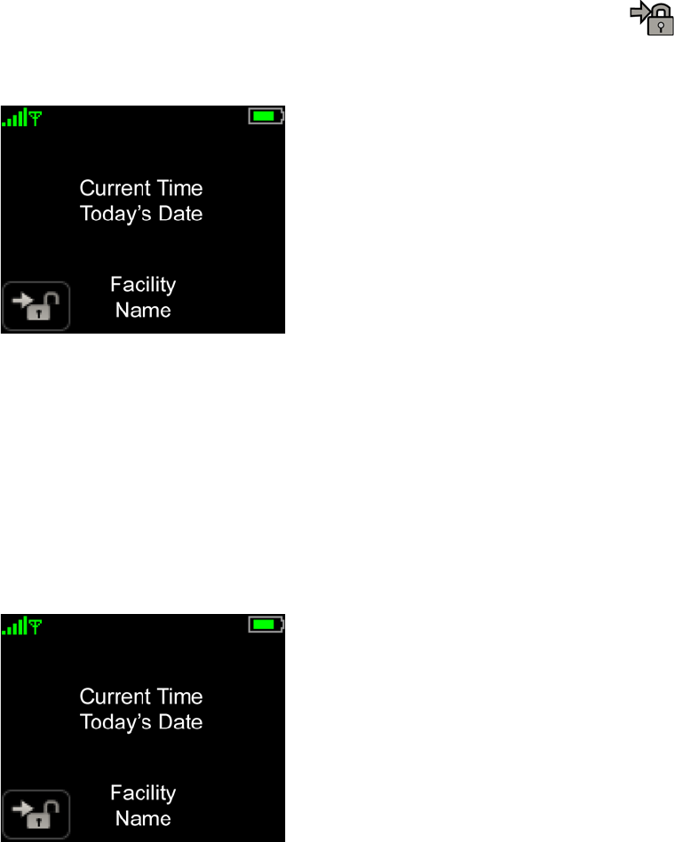
Securing the Monitor
114
8.2 Securing the Monitor
8.2.1 Locking the Monitor
When you have finished working with the Monitor, you should lock the Monitor to prevent the patient
from accidentally accessing clinical settings.
To lock the Monitor
1. When you are finished interacting with the patient and the Monitor, touch Lock.
The Vital Signs screen is locked to prevent settings from being inadvertently changed. The Patient
View screen appears.
8.2.2 Unlocking the Monitor
If your System is configured to require authorization to view the Vital Signs screen, you must first unlock
the Monitor by entering a PIN code. If you do not have a PIN code, please see your system administrator.
If your System is not configured to require authorization, the Enter Pin Code screen does not appear.
To unlock the Monitor
1. With one finger, touch the Monitor’s screen for two seconds to activate the Monitor’s display.
The Patient View screen appears.
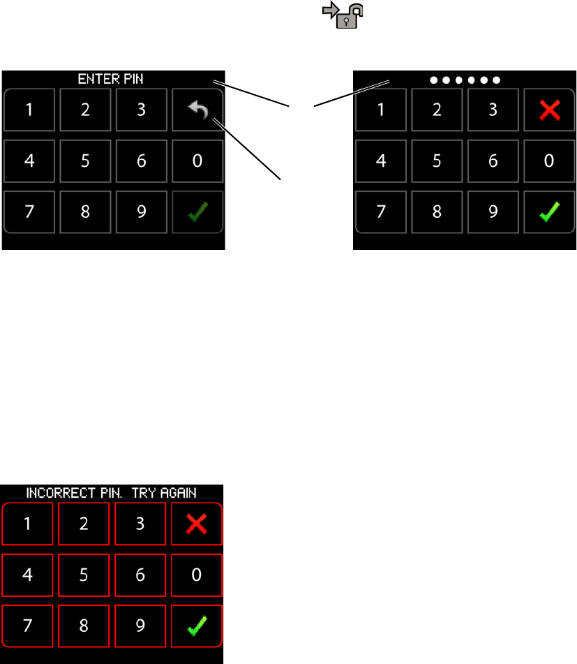
Securing the Monitor
115
2. Touch Unlock in the lower left corner of the screen.
The Enter PIN Code screen appears.
3. Enter PIN code on the PIN code pad.
As PIN digits are entered, a white dot appears in the message area for each digit entered and the
Return to Previous Screen button changes to a Cancel button.
4. Touch Confirm to enter the PIN code and confirm authorization.
If you touch the Confirm button the system navigates to the Vital Signs screen (when a valid PIN
code has been entered). If you touch the Cancel button, the entered PIN code is cleared and the
Return to Previous Screen button appears, allowing the return to the Patient View screen.
Note: When an invalid PIN code is entered, the outline of the PIN code buttons will flash red and
the entered PIN code is cleared.
Message
area
Return to
previous
screen
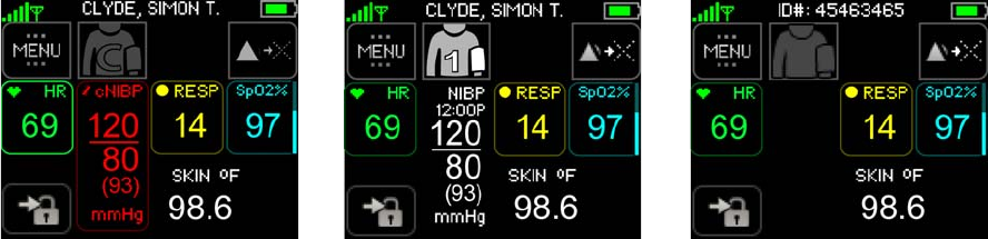
Patient Monitoring
116
8.3 Patient Monitoring
8.3.1 Viewing Vital Signs
Vital signs monitoring, with alarms, starts as soon as a sensor is connected to the patient and plugged into
the Monitor. When there has been no interaction with the Monitor for a period of time, the display goes
into Quiet Monitoring.
To view vital signs
1. With one finger, touch the Monitor screen for two seconds to activate the display.
2. Enter your PIN code if required. See To unlock the Monitor on page 114.
The Vital Signs screen appears and displays all currently monitored vital signs.
Note: If the Cuff Module is not connected and NIBP is not being measured continuously (cNIBP),
the Start NIBP button is disabled and the NIBP numeric display area is blank.
Note: If the Cuff Module is not connected and NIBP is being measured continuously (cNIBP), the
Calibrate cNIBP button is disabled. The NIBP measurements will continue to be displayed.
Note: Systolic, diastolic and MAP measurements will be displayed in red when measuring NIBP
continuously (cNIBP).
Note: The vital sign measurements are refreshed every 3 seconds.
Continuous Measurements
Cuff Module not connected Single Measurement
Cuff Module not connected
Single Measurement
Cuff Module connected
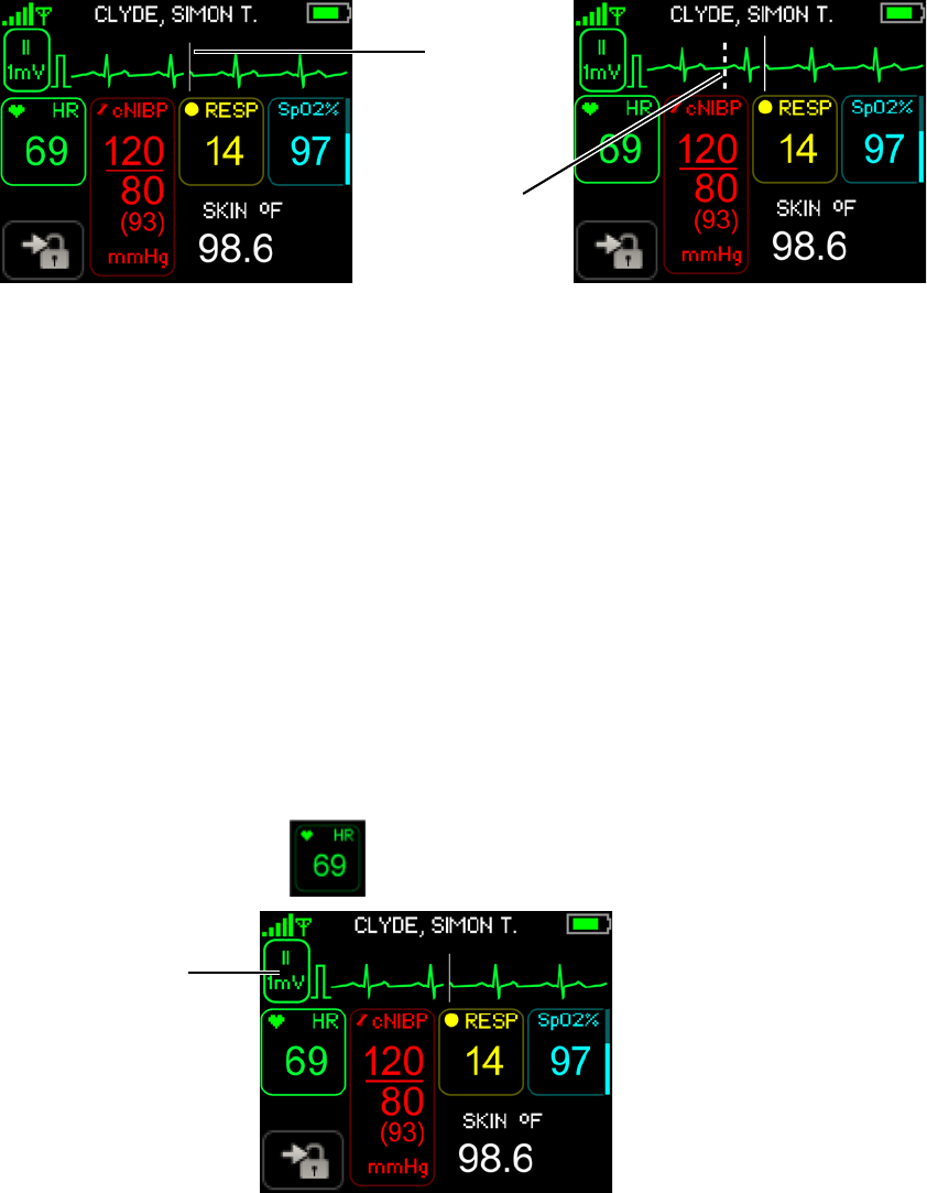
Patient Monitoring
117
8.3.2 Viewing Waveforms Associated with Vital Signs
Waveforms move across the display from left to right. A sweep bar erases the oldest waveform and
replaces it with the newest waveform as it moves from left to right.
The speed of the waveform display (sweep speed) is scaled to 25 mm/sec for ECG, and SpO2 waveforms.
The sweep speed of the RESP waveform display is scaled to 6.25 mm/sec. The RESP frequency is less
than the ECG or SpO2. The slower sweep speed for the RESP waveform compensates for the lower
frequency of activity in order to display several RESP cycles on the display.
Note: The NIBP (manual or continuous) and skin temperature measurements do not have a
waveform.
To view the ECG waveforms
Depending on which Chest Sensor is connected (3 lead-wire or 5 lead-wire), several views (leads) of the
ECG waveform may be available for view.
Note: It is recommended that you step through the available ECG waveform leads to confirm the
ECG setup is correct.
1. Touch the HR numeric.
The top third of the display is replaced with the ECG waveform. The displayed lead is indicated to
the left of the waveform. The square wave indicates the standard calibration of the ECG waveform.
Sweep
Pacer
Spike
Bar
ECG Lead
selection
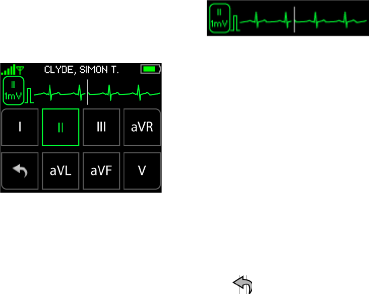
Patient Monitoring
118
To view other leads with the Chest Sensor
1. Touch ECG Lead Selection or the waveform.
The lower part of the display is replaced with Lead Selection buttons.
2. Select the lead corresponding to the waveform that you want to view.
All available leads can be viewed one at time from this view.
Note: Selecting different leads to view has no effect on monitoring. All available leads are
monitored simultaneously and continuously. The lead selection affects only the display.
3. Touch Return to Previous Screen to exit this view.
The display returns to the previous view of the ECG waveform and vital signs.
4. To return to the main Vital Signs screen, touch the HR numeric.
The ECG waveform is no longer displayed.
Note: When you touch a vital sign, its corresponding waveform is displayed, even if another
waveform is currently displayed.
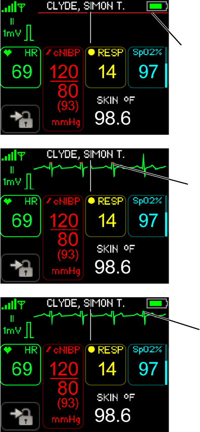
Patient Monitoring
119
Input Overload / Dynamic Range
The ViSi Mobile Monitor display indicates an input overload condition (i.e. the input dynamic range of the
amplifier associated with the displayed ECG lead has been exceeded) by displaying the trace in red at the
top (or bottom) of the ECG waveform display area.
Note: When an input overload / dynamic range issue occurs, check the lead fail status.
Amplifier is overloaded due to an input
that exceeds the positive limit of the
dynamic range on a continuous basis
Positive limit of the dynamic range is
being exceeded only at the peaks of the
QRS complex of the ECG waveform
Dynamic range of the ECG amplifier
has not been exceeded. The peaks of
the QRS complex of the ECG waveform
extend beyond the upper edge of the
display area
basis
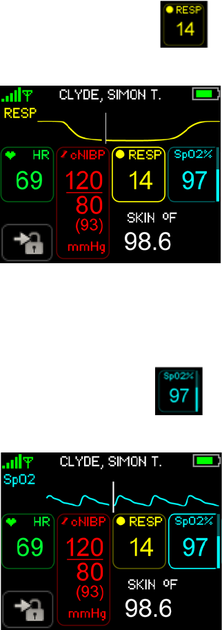
Patient Monitoring
120
To view the RESP waveform
1. Touch the RESP numeric.
The top third of the display is replaced with the RESP waveform.
2. To return to the main Vital Signs screen, touch the RESP numeric.
The RESP waveform is no longer displayed.
To view the SpO2 waveform
1. Touch the SpO2 numeric.
The top third of the display is replaced with the SpO2 waveform.
2. To return to the main Vital Signs screen, touch the SpO2 numeric.
The SpO2 waveform is no longer displayed.
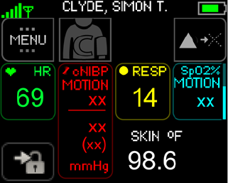
Patient Monitoring
121
8.3.3 Motion Artifact
If a vital sign cannot be measured due to a motion artifact, the word “MOTION” displays below the vital
sign name, and “xx” is displayed in place of the numeric(s). See SpO2 below.

Setting Up/Taking NIBP Measurements
122
8.4 Setting Up/Taking NIBP Measurements
The industry-standard technique of oscillometry is used for non-invasively measuring systolic blood
pressure (SBP) and diastolic blood pressure (DBP). The method is based on the measurement of
oscillations through the occluding cuff which is placed on the patient’s upper arm during an NIBP
measurement. The pulsatile oscillations are measured using a pressure transducer, and then digitized using
a microprocessor. The NIBP algorithm uses the digitized oscillations and applied cuff pressure as input to
an empirical model to calculate SBP and DBP.
Blood pressure measurements can be affected by the patient’s position and/or physiological condition:
• The cuff should be at the same level as the patient’s heart.
• NIBP measurements may not be reliable in the presence of atrial fibrillation or ventricular
arrhythmias.
• Improper cuff size or application may lead to inaccurate readings.
Note: The ViSi Mobile Cuff Module cannot be used with the auscultatory method of measuring
NIBP.
The ViSi Mobile Monitor should never be used to measure the NIBP of one
patient while the Monitor is simultaneously connected to another patient.
Do not attempt to take NIBP measurements with the ViSi Mobile Monitor
while the patient is undergoing cardio-pulmonary bypass.
Do not attempt to take NIBP measurements with the ViSi Mobile Monitor
while the patient is being treated with an intra-aortic balloon pump or left
ventricular assist device.
Periodically observe the patient’s arm for signs of impaired circulation, which
may be a result of NIBP measurements made too frequently. Loosen or
remove the ViSi Mobile Disposable Cuff if signs and/or symptoms of
prolonged impaired circulation are evident.
If you are uncertain of the reliability of an NIBP measurement, repeat the
measurement. If the reading is still suspect, use another method to measure
the blood pressure.
The ViSi Mobile Disposable Cuff should be snug enough to support the Cuff
Module while not impairing circulation when deflated.
Avoid touching the ViSi Mobile Disposable Cuff during cuff inflation as it may
disrupt the measurement.
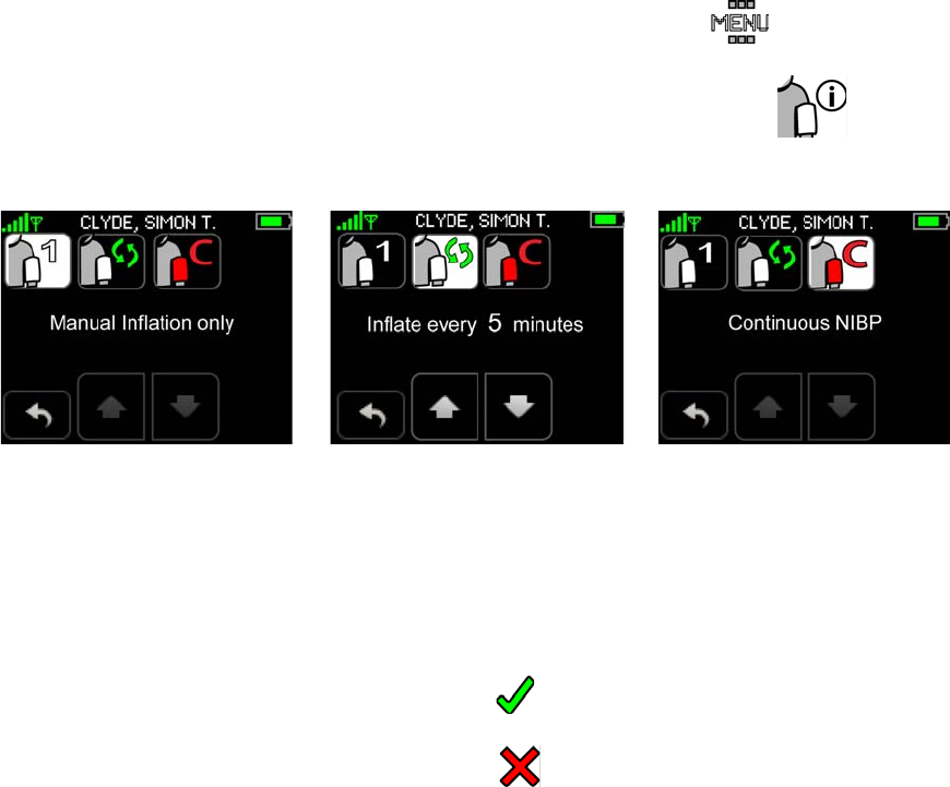
Setting Up/Taking NIBP Measurements
123
8.4.1 Selecting Blood Pressure Mode
Note: The Monitor will automatically default to a NIBP mode depending on which sensors are
connected. You only need to select a NIBP mode if you want to change the default.
To select the blood pressure mode
1. Navigate to the BP Management screen:
a. Touch Menu on the Vital Signs screen to display the Menu screen.
The Menu screen appears.
b. Touch Blood Pressure Settings to display the BP Management screen.
The BP Management screen appears.
Note: On initial entry into the BP Management screen, the default blood pressure mode will
automatically be selected. The default mode is dependent on the connected sensors and the
cNIBP license.
2. Select the desired NIBP mode.
a. If Automatic is selected, touch the Up or Down arrow to increase or decrease the time interval.
b. Touch Confirm to confirm the new settings.
- or -
Touch Cancel to return to the Menu screen.
Once you have touched Confirm, the cuff inflation method setting is saved and the system returns
to the Vital Signs screen. If you touch Cancel, the system discards the changed settings and returns
to the Menu screen.
Note: As long as the NIBP Module is plugged in, a manual NIBP measurement can be initiated at
any time. When the NIBP mode is set to Automatic, if the timing of the manual measurement
overlaps with the automatic measurement interval, then that automatic measurement is
skipped; otherwise the automatic measurement occurs as scheduled.
Note: Touching the “Stop NIBP” button on the Vital Signs screen interrupts any NIBP
measurement cycle presently in progress. When the NIBP mode is set to Automatic, the next
automatic measurement will occur as scheduled.
Note: To calibrate cNIBP, the Chest Sensor, Thumb Sensor and Cuff Module are required. After
calibration, the Cuff and Cuff Module may be removed.
Automatic
Cuff Inflation
Manual
Cuff Inflation cNIBP
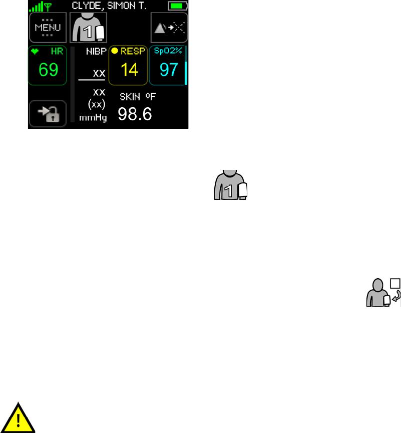
Setting Up/Taking NIBP Measurements
124
8.4.2 Taking a NIBP Measurement
This section describes how to take a single NIBP measurement and how to initiate automatic NIBP
measurements at various intervals. For patient comfort, when the NIBP is set to manual, remove the Cuff
and the Cuff Module from the patient's arm. Once removed, disconnect the Cuff Module from the Monitor
between measurements. Store the Cuff and Cuff Module in a convenient location.
To take a single NIBP measurement
1. Apply the Cuff and Cuff Module. See Applying the ViSi Mobile Cuff Module and Disposable Cuff
on page 75.
After the Cuff Module has been connected to the Monitor, the NIBP vital sign numerics (Systolic,
Diastolic and MAP) display as “xx”, indicating no measurement has been taken.
2. Touch Start NIBP to start a measurement.
After a few seconds to zero and calibrate the barometric pressure, the Cuff begins inflating.
An inflation pressure indicator bar, located to the left of the NIBP numerics, increases/decreases in
height as the pressure increases/decreases in the Cuff. The actual cuff pressure is displayed under
the NIBP label.
Once the Cuff begins to inflate, the Start NIBP button changes to Stop NIBP.
Note: If unexpected readings occur, confirm the correct application of the ViSi Mobile Disposable
Cuff (see page 75) and then retake the measurementIf the measurement is still suspect, check
NIBP by another method and have maintenance performed as described in the Technical
Reference Manual.
Note: If viewing a waveform, the Start NIBP button will be hidden.
The performance of the automated sphygmomanometer may be affected by
extremes of temperature, humidity and altitude.
Manual / Automatic
Cuff Inflation
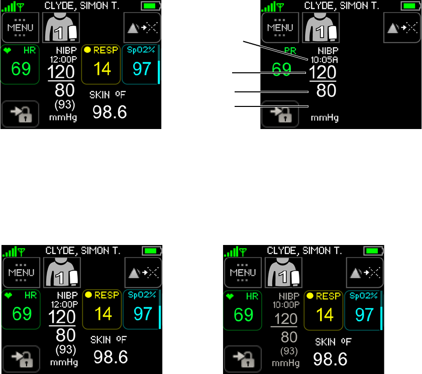
Setting Up/Taking NIBP Measurements
125
Upon completion of a successful measurement, the Systolic, Diastolic and MAP measurements are
displayed in white. The time of the measurement is displayed below the NIBP label. If there is no other
heart rate/pulse rate source (i.e. Thumb Sensor or Chest Sensor are not connected to the Monitor), then a
one-time PR from the NIBP measurement is displayed for 30 seconds.
Note: If the NIBP measurement was unsuccessful, the Cuff Module automatically retries to
measure the blood pressure. “Retry” messages appear on the screen directly below the NIBP
label. A maximum of 3 attempts will be made.
Note: If the failure is due to a cuff leak or cuff occlusion, there is no retry and the LEAK or OCCL
message appears on the screen directly below the NIBP label.
NIBP numerics fade and shrink in size after 30 seconds to indicate that the reading is not recent.
NIBP measurements that are older than 30 minutes are no longer displayed.
Time of
Systolic
Diastolic
Measurement
MAP
Current Reading Older Reading
Note that the numerics for the older
reading are faded and shrunken in size
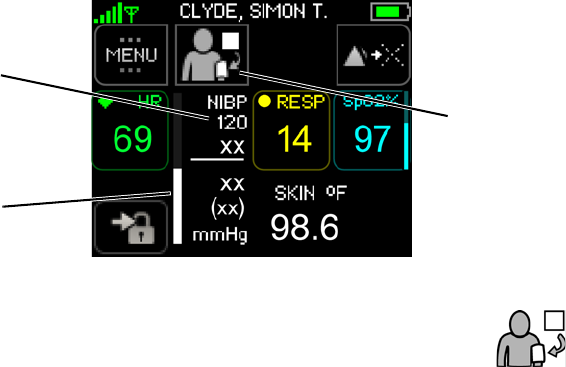
Setting Up/Taking NIBP Measurements
126
To stop an NIBP measurement
An NIBP measurement currently in progress may be stopped at any time.
Touch Stop NIBP to stop the cuff inflation and NIBP measurement.
The cuff will deflate.
Inflation Pressure
Indicator Bar
Inflation Pressure
(mmHg)
Stop Cuff

Setting Up/Taking NIBP Measurements
127
8.4.3 Initiating Automatic NIBP Measurements
When frequent NIBP measurements are required, the Monitor can be set up to automatically take a blood
pressure measurement every 5, 10, 15, 30, 60, 90 or 120 minutes.
To initiate automatic NIBP measurements
1. Apply the Cuff and Cuff Module, if not already on the patient.
See Applying the ViSi Mobile Cuff Module and Disposable Cuff on page 75.
2. Set the NIBP mode to Automatic, if the mode is not already Automatic.
See Selecting Blood Pressure Mode on page 123.
3. On the Vital Signs screen, touch Automatic Cuff Inflation.
See Taking a NIBP Measurement on page 124
An automatic NIBP measurement is taken immediately, and again at the set interval.
Note: As long as the NIBP Module is plugged in, a manual NIBP measurement can be initiated at
any time. If the timing of the manual measurement overlaps with the automatic
measurement interval, then that automatic measurement is skipped; otherwise the automatic
measurement occurs as scheduled.
Note: Touching the “Stop NIBP” button on the Vital Signs screen interrupts any NIBP
measurement cycle presently in progress. The next automatic measurement will occur as
scheduled.
Use care when using automatic cuff inflation for prolonged periods on
unconscious or semi-conscious patients since the patient may not be able to
alert the clinician to any pain he/she may be experiencing. Pressing the
“Stop NIBP” button interrupts the NIBP measurement and deflates the cuff.

Setting Up/Taking NIBP Measurements
128
8.4.4 Calibrating Continuous NIBP Monitoring
Sotera’s continuous blood pressure monitor (cNIBP) is based on the relationship between blood pressure
and the time it takes a pulse that originates from a cardiac contraction to arrive at a peripheral location.
Pulse Arrival Time (PAT) is measured from the time an ECG R-Wave is detected to its arrival at the SpO2
thumb sensor. The shorter the time, the higher the blood pressure. Calibration of PAT for an individual
patient requires an initial NIBP cuff measurement. Once this measurement is made, continuous blood
pressure is displayed based on averaging PAT calculations from the previous 60 seconds and updating the
display every three seconds.
Calibrate whenever any of the following conditions occur:
• A new patient starting cNIBP monitoring for the first time.
• A monitor has been swapped.
Note: Recalibrate whenever an alert message requesting cNIBP calibration appears on the Monitor and
Remote Viewer. The message appears when any of the conditions stated in section To recalibrate
cNIBP on page 131 occur. .Continuous NIBP monitoring is an optional feature that requires
an additional license key.
The accuracy of cNIBP is dependent on the initial cuff calibration. Use good
clinical practice to confirm cNIBP accuracy before initiating or treating a
patient.
The accuracy of the cNIBP measurement cannot be relied upon in patients
with a BMI greater than 35.
The ViSi Mobile Monitoring System accuracy claim (mean error of ≤ ±5
mmHg and a std. dev. of ≤ 8 mmHg) is not met when the subject is in a
semi-Fowlers position (inclined more than 30 degrees from horizontal).
Due to cNIBP signal averaging, there is a time delay of up to 120 seconds
between the instantaneous blood pressure reading and the displayed
reading.
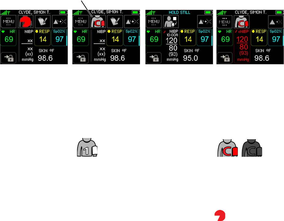
Setting Up/Taking NIBP Measurements
129
To calibrate NIBP for continuous monitoring
1. Connect the ViSi Mobile Chest Sensor, Thumb Sensor and Cuff Module and navigate to the Vitals
Signs screen.
Note: Have the patient positioned in a supine, semi-Fowler’s, or side-lying position during cNIBP
calibration.
The Start Cuff button will change to the Calibrate cNIBP button.
When the patient’s PAT, posture and arm height are stable for approximately 30 seconds, the
Calibrate cNIBP button appears with a red cuff indicating cNIBP is ready to be calibrated.
When the patient’s PAT, posture or arm height is not stable for approximately 30 seconds, the
Calibrate cNIBP button is disabled. The button will be disabled until the patient’s PAT, posture
and arm height are stable.
Note: When the criteria to calibrate cNIBP has not been met, a pie symbol will be displayed on
top of the disabled “cNIBP Calibrate” button. The pie will fill and empty to reflect the
readiness of the calibration criteria: patient’s PAT, posture and arm height are stable for
approximately 30 seconds.
If the patient’s posture has not already been confirmed, you will be prompted to confirm the posture before
the cNIBP process starts. See “To Select/Confirm the Patient’s Posture” on page 132.
Note: The patient should not move until after the red cNIBP measurements are displayed.
2. Touch Calibrate cNIBP on the Vital Signs screen.
The Cuff will start to inflate, indicating the calibration process has started. After a single NIBP
measurement has been taken, the ViSi Mobile Monitor will calibrate cNIBP. The NIBP
measurement will be displayed in white during the calibration process.
After cNIBP has been calibrated, Systolic, Diastolic and MAP measurements will be displayed in
red. The displayed measurement will be refreshed every 3 seconds.
Note: The calibration process takes approximately 1 to 2 minutes to complete.
Note: If the calibration is not successful, the monitor will use the previous calibration curve (if it
exists). If no previous calibration curve exists, the NIBP measurements will continue to show
in white text. The failure will be indicated by a “Calibration Failed” alert.
Start Calibration
cNIBP Calibrated
Start calibration
(Calibrate cNIBP
Criteria to calibrate
cNIBP has not
yet been met
Spot-Check
Reading Displayed
button enabled)
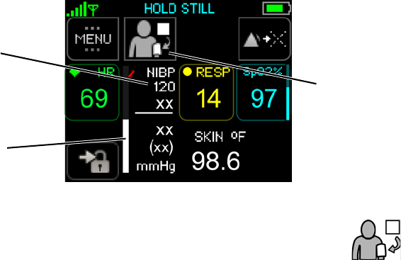
Setting Up/Taking NIBP Measurements
130
After the calibration process is completed, it is acceptable for the patient to change position.
Note: The accuracy of cNIBP measurements have not been confirmed when the posture is greater
than a semi-Fowler’s position of 30 degrees.
3. Remove the Cuff from the patient and the ViSi Mobile Cuff Module from the Monitor.
The continuous measurements will continue to display/update even after the cuff has been
disconnected.
To stop the cNIBP calibration
A cNIBP calibration currently in progress may be stopped at any time.
Touch Stop NIBP to stop the cuff inflation and NIBP measurement.
The cuff will deflate.
Inflation Pressure
Indicator Bar
Inflation Pressure
Stop Calibration
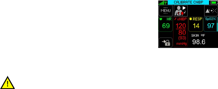
Setting Up/Taking NIBP Measurements
131
To recalibrate cNIBP
On the Monitor and Remote Viewer, a “Calibrate cNIBP” message appears when any of the following
events occur:
• The MAP measurement changed since calibration by ±30% or more for a period longer than 5
minutes.
• A cNIBP calibration has been continuously unavailable for four hours.
• An unexpected interruption of monitoring occurred, such as all sensors being disconnected. If the
interruption is less than 30 seconds, no recalibration is required. See section All Sensors
Disconnected on page 145.
• A vasoactive drug is administered to the patient.
• IV vasoactive drug administration: Recalibrate within 3-5 minutes of drug administration.
• Oral administration of vasoactive drugs for the first time: Recalibrate based on the onset of the
drug action.
• Change in the ECG pattern.
To manually recalibrate cNIBP, following the steps outlined in section To calibrate NIBP for continuous
monitoring on page 129.
Note: When a recalibration event is detected, the ViSi Mobile
Monitor will display the Calibrate cNIBP alert. Connect
the Cuff Module, if not already connected, and
recalibrate manually.
You should manually recalibrate cNIBP after the administration of an IV
vasoactive drug or a new oral vasoactive drug. The Calibrate cNIBP alert
will not be displayed.
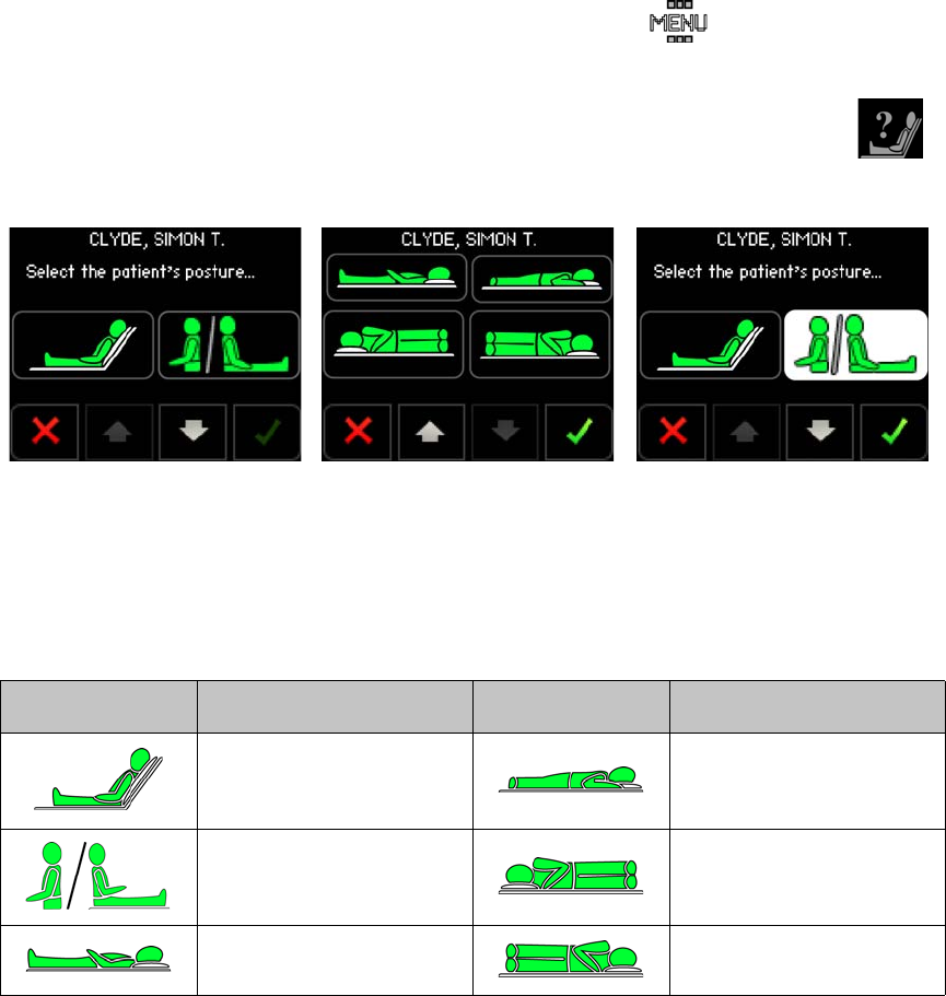
Patient’s Posture
132
8.5 Patient’s Posture
Note: When cNIBP is initiated for the first time, the Posture Selection screen will automatically
display before calibration starts. The patient’s posture must be selected and confirmed
before cNIBP can be calibrated. See Calibrating Continuous NIBP Monitoring on page 128.
To View the Patient’s Posture
1. Navigate to the Patient Information screen.
See Viewing Patient’s Demographics on page 134.
To Select/Confirm the Patient’s Posture
1. Touch Menu on the Vital Signs screen to display the Menu screen.
The Menu screen appears.
2. Touch Patient Posture on the Menu screen to display the Select Patient Posture screen.
The Select Patient Posture screen is displayed.
3. Select the posture button that matches the patient’s current posture.
You may need to touch the up or down arrows to view all the postures. Once selected, the button
will display as highlighted.
Posture Icon Description Posture Icon Description
Patient is in a reclined
position (semi-Fowler’s
position).
Patient is lying on their
front/prone position.
Patient is either standing,
walking or sitting upright.
Patient is lying on the right-
hand side.
Patient is lying on their
back.
Patient is lying on their left-
hand side.
First set of
postures Second set of
postures Posture selected
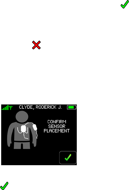
Patient’s Posture
133
4. Touch Confirm to confirm the selected posture is correct.
The Confirm button will be disabled until a posture has been selected.
- or -
Touch Cancel.
If cancelled, the selected posture will be discarded and the Select Patient’s Posture screen will be
closed. You will be returned to the screen from where the select posture was initiated.
If confirmed and the selected posture matches the calculated posture, the selected posture will be
saved. The Select Patient’s Posture screen will be closed and you will be returned to the screen
from where the select posture was initiated.
If the selected posture does not match the calculated posture, the Confirm Sensor Placement
screen will be displayed.
5. Check the sensor placements and touch Confirm to confirm the sensors are positioned correctly.
You may need to reposition the Chest Module Cable as shown in the screen image above.
Note: When the posture is selected as part of the cNIBP calibration process, the calibration process
will continue after the selection is made.
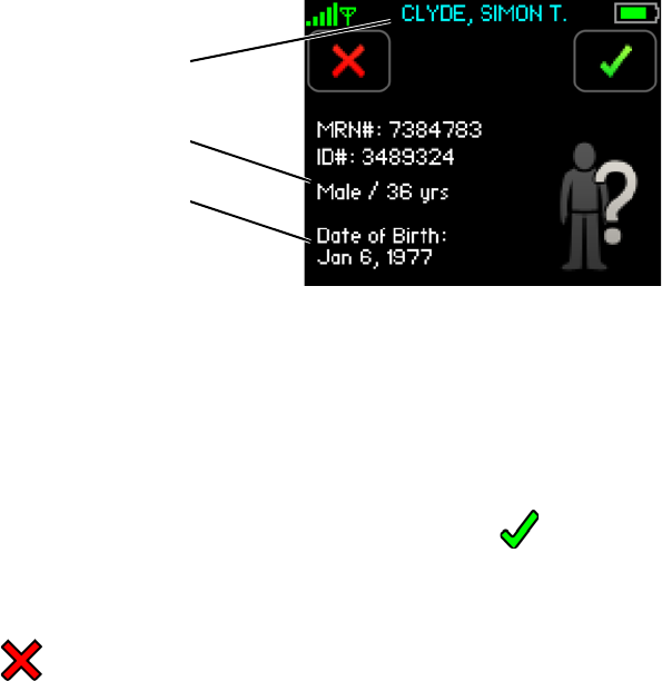
Viewing Patient’s Demographics
134
8.6 Viewing Patient’s Demographics
To Confirm Patient’s Demographics
When the patient’s demographics have been changed on the ViSi Mobile Remote Viewer or there is an
interruption of monitoring of more than 30 seconds, the demographics must be confirmed (or rejected)
directly on the ViSi Mobile Monitor.
Note: The patient’s primary ID will be displayed in blue to indicate the demographics have been
changed and require confirmation.
Note: The primary ID is configured to be the patient’s name. The secondary ID is configured to be
the patient’s MRN#. The tertiary ID is configured to be an alternative ID.
1. Touch Confirm to confirm the patient’s demographics are correct.
- or -
Touch Cancel.
If cancelled, the patient’s demographics will be removed from the ViSi Mobile Monitor and an
alert will be annunciated on the ViSi Mobile Remote Viewer.
If confirmed, the patient’s demographics will be displayed in white to indicate they have now been
confirmed.
Patient’s Primary (displayed in blue)
Secondary and Tertiary IDs
Birth Gender / Age
Date of Birth
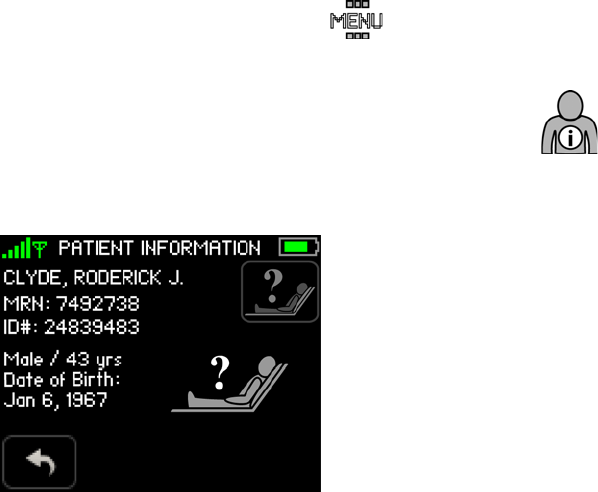
Viewing Patient’s Demographics
135
To View Patient’s Demographics
1. Touch Menu on the Vital Signs screen to display the Menu screen.
The Menu screen appears.
2. Touch Patient Information on the Menu screen to display the Patient Information screen.
The Patient Information screen is displayed.
Note: The patient’s demographics are entered on the ViSi Mobile Remote Viewer.
The patient’s posture will be displayed on this screen. See Patient’s Posture on page 132.
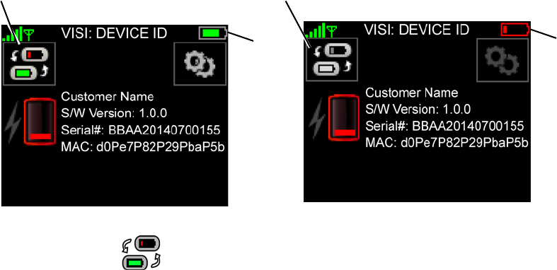
Exchanging a Monitor With Low Battery
136
8.7 Exchanging a Monitor With Low Battery
To exchange a monitor with a low battery
When the ViSi Mobile Monitor’s battery becomes low during monitoring, it may be exchanged with a new
Monitor without stopping the patient’s monitoring session.
Note: You will not be able to exchange the monitoring using the method described below if the
monitor’s battery is too low to monitor.
1. Remove the new Monitor from the ViSi Mobile Charger.
The Device Status screen will be displayed.
2. Touch Device Swap.
The Exchange Instructions screen will be displayed and the Monitor will connect to the network.
of the new monitor is too low
Button is disabled when the battery life
Device Swap Button
Battery
Status
Battery
Status
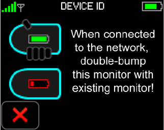
Exchanging a Monitor With Low Battery
137
Note: The Monitor may take a few seconds to connect to the network. Do not attempt to bump the
two monitors together until the new Monitor has connected to the network.
Note: The two Monitors must be double-bumped together such that the long ends of the Monitors
make contact with each other. See the image on the ViSi Mobile Monitor Instructions screen
above.
Note: You must be logged into the patient’s current monitor before bumping the two monitors
together.
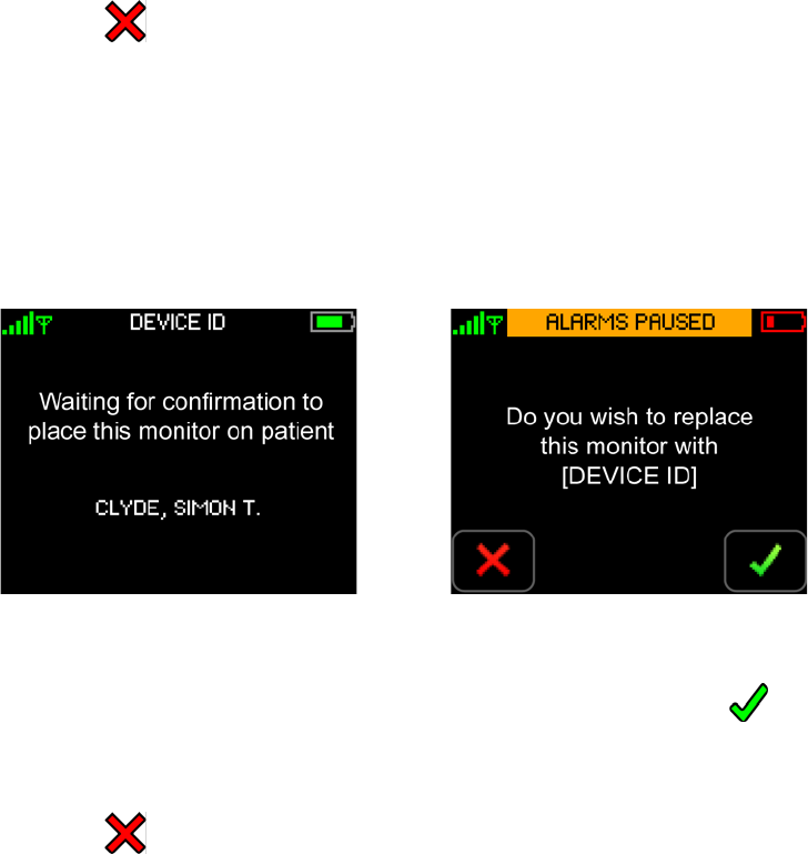
Exchanging a Monitor With Low Battery
138
3. Double bump the new Monitor with the Monitor on the patient’s wrist.
- or -
Touch Cancel.
If cancelled, the Device Swap will automatically be cancelled.
If the monitors are successfully double bumped, the Exchange process will be initiated. The new
Monitor will display the Waiting Patient Transfer screen and the patient’s Monitor will display the
Confirm Device Swap screen.
Note: Once the Exchange process has been initiated, the alarms will be paused on the patient’s
current Monitor. Alarms will be paused until the process is successfully completed or
cancelled.
4. Touch Confirm to replace the existing patient’s Monitor with the new Monitor.
- or -
Touch Cancel.
If cancelled, the Exchange process will automatically be cancelled.
If confirmed, the patient’s monitoring session will be transferred from the patient’s current
Monitor to the new Monitor.
The new Monitor will display the Instructions screen and the patient’s old Monitor will display
the Clean Monitor screen.
Waiting Patient Transfer Confirm Device Swap
(Instructions on the new Monitor) (Instructions on the patient’s Monitor)
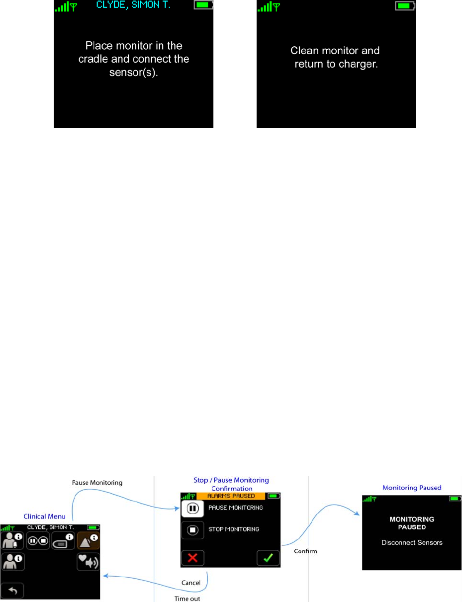
Pause Monitoring
139
Note: If the clinician has not already authenticated on the patient’s current monitor before the
device exchange is initiated, the clinician will be prompted to authenticate before the Clean
Monitor screen is displayed.
Note: If the clinician has not confirmed the patient’s id on the patient’s current monitor, the
clinician will be prompted to confirm the patient’s id before the Clean Monitor screen is
displayed.
5. To restart monitoring, place the new Monitor into the Wrist Cradle (attached to the patient’s wrist)
and connect the sensors.
Note: When monitoring is restarted, the patient’s demographics will need to be reconfirmed on the
new Monitor.
Note: Once the device swap has been successfully completed, the cuff inflation method will transfer
to the new monitor.
cNIBP will need to be calibrated/initiated on the new Monitor.
8.8 Pause Monitoring
Pause monitoring when vital signs monitoring needs to be stopped temporarily and you intend to restart
monitoring the same patient with the same monitor.
Note: Monitoring may not be paused until the patient’s demographic data has been confirmed (on
the Monitor).
Instructions Clean Monitor
(Patient’s New Monitor) (Patient’s Old Monitor)
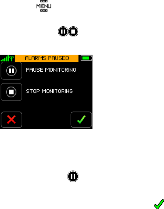
Pause Monitoring
140
To pause monitoring
1. With one finger, touch the Monitor screen for two seconds to activate the display.
The Patient View screen appears.
2. Enter your PIN code if required. (See To unlock the Monitor on page 114.)
The Vital Signs screen appears.
3. Touch MENU.
The Menu screen appears.
4. Touch PAUSE / STOP.
The Pause/Stop Monitoring screen appears.
Note: Once the Pause/Stop Monitoring process has been initiated, the alarms will be paused until
the process is successfully completed or cancelled.
5. Touch Pause Monitoring.
The Confirm button will be enabled.
6. Touch Confirm to confirm that you want to stop monitoring.
- or -
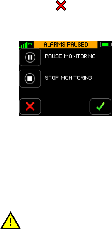
Pause Monitoring
141
Touch Cancel.
If cancelled, the program returns to the Menu screen and monitoring continues uninterrupted.
If confirmed, the Monitoring Paused screen is displayed. Monitoring is paused effective
immediately.
Note: Remove all the sensors from the Monitor and the patient.
Note: To remove the sensors from the Monitor, grasp the sensors near the plug, and while holding
the Monitor firmly, pull out the plug.
If you want to stop monitoring permanently, follow the steps outlined in section 8.9 Stop Monitoring on
page 142.
When monitoring has been paused, monitoring may only be resumed using
the same ViSi Mobile Monitor. If you place the ViSi Mobile Monitor into the
Charger with other Monitors, label the Monitor so that is can be identified
when monitoring is to be resumed.
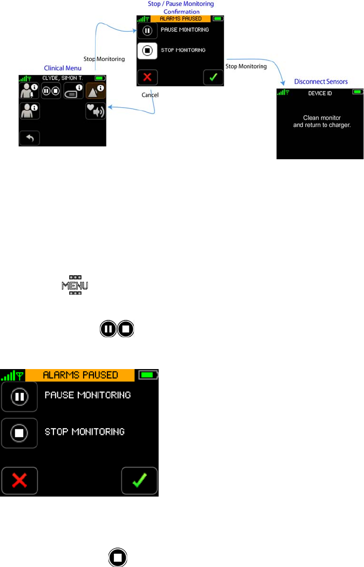
Stop Monitoring
142
8.9 Stop Monitoring
Stop monitoring when ALL vital signs monitoring is no longer required.
To stop monitoring
1. With one finger, touch the Monitor screen for two seconds to activate the display.
The Patient View screen appears.
2. Enter your PIN code if required. (See To unlock the Monitor on page 114.)
The Vital Signs screen appears.
3. Touch MENU.
The Menu screen appears.
4. Touch PAUSE / STOP.
The Pause/Stop Monitoring screen appears.
Note: Once the Stop Monitoring process has been initiated, the alarms will be paused until the
process is successfully completed or cancelled.
5. Touch Stop Monitoring.
The Confirm button will be enabled.
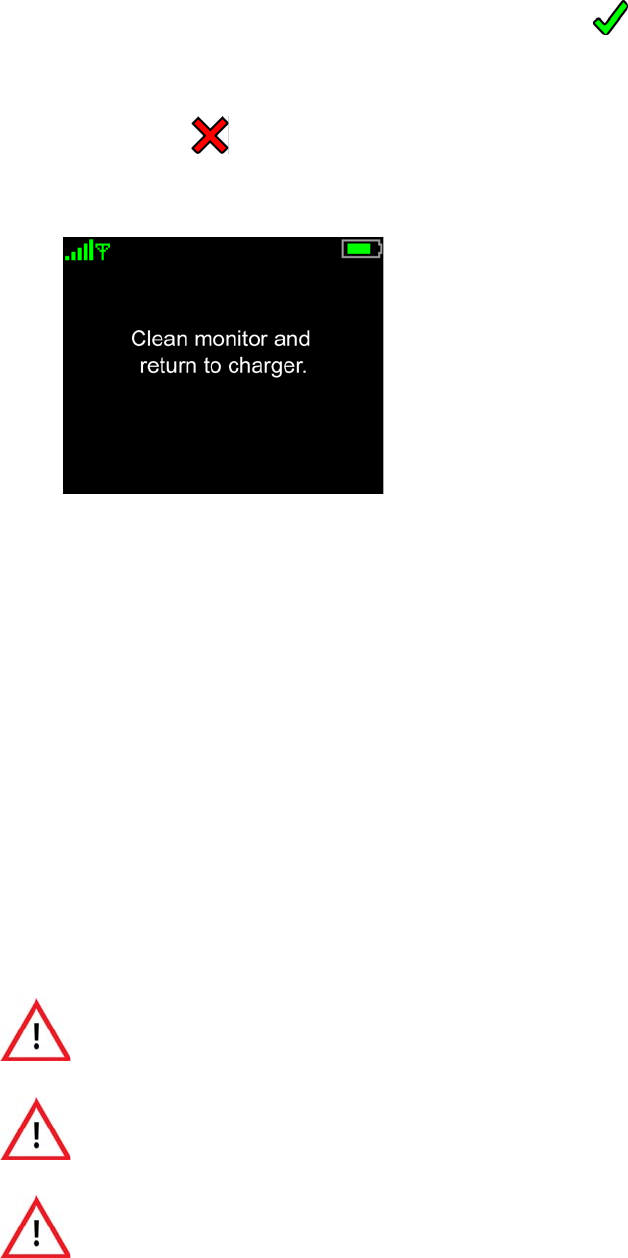
Stop Monitoring
143
6. Touch Confirm to confirm that you want to stop monitoring.
- or -
Touch Cancel.
If cancelled, the program returns to the Menu screen and monitoring continues uninterrupted.
If confirmed, the Clean Monitor screen is displayed. Monitoring is stopped effective immediately.
Note: Remove all the sensors and the Monitor from the patient.
Note: To remove the sensors from the Monitor, grasp the sensors near the plug, and while holding
the Monitor firmly, pull out the plug.
7. Dispose of disposable components per your facility’s procedures.
If you want to pause monitoring temporarily, follow the steps outlined in section 8.8 Pause Monitoring on
page 139.
To clean and prepare reusable components
1. Clean and prepare the reusable components of the System (Monitor, Chest Sensor, Thumb Sensor,
and Cuff Module) in accordance with your facility’s procedures and the cleaning recommendations
in this manual. See section 7. User/Preventative Maintenance on page 105.
2. Place the cleaned Monitor and Cuff Module into the Charger.
Never place the ViSi Mobile Monitor, the ViSi Mobile Cuff Module, or the
ViSi Power Pack into the ViSi Mobile Charger while connected to a patient.
Never connect the ViSi Mobile Monitor directly to an AC power outlet. To
recharge the battery, disconnect the Monitor from the patient, and then place
it in the ViSi Mobile Charger.
Never connect the ViSi Mobile Cuff Module directly to an AC power outlet.
To recharge the battery, disconnect the Cuff Module from the patient, and
then place it in the ViSi Mobile Charger.

Stop Monitoring
144
If the ViSi Power Pack beeper/buzzer sounds or the Red LED is
permanently lit, the ViSi Power Pack should be disconnected from the
patient immediately.
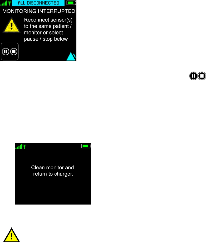
All Sensors Disconnected
145
8.10 All Sensors Disconnected
The “All Sensors Disconnected” screen will be displayed when the last sensor is disconnected from the
ViSi Mobile Monitor without going through the proper “Stop Monitoring” procedure. (see 8.6Viewing
Patient’s Demographics on 134). An “All Disconnected” alert will be generated.
1. To stop monitoring the patient, touch Stop to initiate the Stop Monitoring process.
- or -
to resume monitoring, connect the sensor(s) to restart monitoring.
Monitoring will automatically continue.
2. Enter your PIN code if required. (See To unlock the Monitor on page 114.)
The Clean Monitor screen appears.
Placing the ViSi Mobile Monitor into the Charger when the “All Sensors
Disconnected” alert is displayed will result in the patient’s monitoring
session being stopped. It is recommended that you follow the correct stop/
pause monitoring flows as outlined in sections 8.8 Pause Monitoring on page
139 and 8.9 Stop Monitoring on page 142.
Disable Skin Temperature
146
8.11 Disable Skin Temperature
In the event that a Facility’s Care Unit chooses to not monitor the Skin Temperature vital sign, that feature
can be turned off through the Facility’s Care Unit .XML configuration file that is pushed from the server.
Note: Only while in Bio Med Mode is it possible to turn the Skin Temperature vital sign “On” or
“Off.” on page 80
Note: Un-Networked/Standalone Monitors are the only Monitors that are able to have Skin
Temperature turned “On” or “Off” while in Bio Med Mode. on page 80
More detailed information can be found: Skin Temperature Configuration on page 80
- Notes -

147
9. Troubleshooting
9.1 Introduction
The ViSi Mobile Monitoring System is designed to alert the clinician to technical issues that may occur
while monitoring a patient’s vital signs.
The following tables provide troubleshooting solutions to potential problems that may be encountered
while monitoring a patient.
9.1.1 Customer Service
Toll-Free: +1-866-232-6126
International: +1-858-427-4620
Fax: +1-858-999-2487
E-mail: support@soterawireless.com

ViSi Mobile Monitor
148
9.2 ViSi Mobile Monitor
9.2.1 Screen Access
Problem Potential Cause Solution
The screen is blank The display is in Quiet
Monitoring Mode.
Touch the screen with one finger for two
seconds to activate display.
Plug in a sensor to initiate monitoring.
The display is in Hibernation
Mode.
Plug in a sensor to initiate monitoring.
The battery charge is too low. Disconnect all sensors from the Monitor,
clean the Monitor, and place it in the
Charger.
Sensors won’t plug into the
Monitor
Plug is oriented with the
connector contacts facing
downwards.
Orient the Plug so that the connector
contacts are facing upwards.
Trying to Plug into wrong end of
the Monitor.
Only the Thumb Sensor is designed to be
Plugged into the rounded end of the
Monitor. All other sensors can be Plugged
into any port on the flat end of the
Monitor.
Monitor is not seated in the
cradle correctly.
Ensure the Monitor is pushed all the way
into the cradle and secure with either the
Thumb Sensor or Locking Plug.
Problem Potential Cause Solution
No response to touching any
buttons
Touching the screen with more
than one finger.
Touch the button with only a single
finger.
Button is not an active button. Active buttons are those with borders, and
are not dimmed in appearance compared
to other buttons.
Touching the screen with a pen
or stylus.
Note: May cause damage
to the touch screen.
Touch the button with only a single
finger.
Cannot access the Vital Signs
screen
Screen is locked. Touch the Unlock button and enter the
correct PIN.
Access denied due to entering
the wrong PIN code.
Enter the correct PIN code.

ViSi Mobile Chest Sensor
149
9.3 ViSi Mobile Chest Sensor
Patient has accessed the
monitoring functions
Screen was not locked after last
clinician interaction.
• Once all interactions are complete,
make sure to lock the screen.
• Remind the patient that this is a med-
ical device, and that tampering may
result in missing important clinical
events.
Patient guessed PIN correctly. • Define appropriate PIN codes (not
0000 for example).
• Remind the patient that this is a med-
ical device, and that tampering may
result in missing important clinical
events.
Problem Potential Cause Solution
Chest Sensor is too short to plug
into the Monitor
Monitor is oriented in the wrong
direction.
Make sure that the flat end of the Monitor
is oriented towards the elbow.
The Chest Sensor is secured to
the side of the chest opposite the
arm with the Monitor.
Secure the Chest Sensor midway between
the sternum and the shoulder of the same
arm that the Monitor is on.
The Chest Sensor Module has
been put on upside down.
Rotate the Chest Sensor Module 180o
such that the leads are facing downwards.
No HR numeric ECG electrodes not connected to
lead-wires.
Ensure that the lead-wires are snapped
securely onto the ECG electrodes.
ECG electrodes not firmly
attached to the patient’s chest.
Ensure that the ECG electrodes are
securely attached to the chest; ECG
electrode sites are clean and free of excess
hair.
ECG electrode gel is dry. Replace ECG electrodes.
Broken/damaged lead-wires. Replace damaged Chest Sensor.
Chest Sensor not securely
Plugged into the Monitor.
Make sure that the Chest Sensor is
securely Plugged into the Monitor.
HR displays “XX” A lead-wire or sensor problem is
affecting the measurement.
If the problem persists, replace the ECG
electrodes and/or Chest Sensor.
Problem Potential Cause Solution

ViSi Mobile Chest Sensor
150
HR is erratic ECG electrodes are not all the
same.
Use all the same ECG electrode type,
size, materials, and manufacturer.
ECG electrode gel is dry. Replace ECG electrodes.
ECG electrodes not firmly
attached to the patient’s chest.
Check that the ECG electrodes are
securely attached to the chest; ECG
electrode sites are clean and free of excess
hair.
Skin is not prepared correctly. See instructions for skin preparation.
No ECG waveform See No HR numeric above. See No HR numeric above.
ECG waveform too small Using a 3-lead Chest Sensor:
Lead II has a low amplitude.
Lead II only available with a 3-
lead Chest Sensor.
• Select alternate ECG electrode sites;
prepare skin sites; connect lead-wires
to new ECG electrodes and place on
the chest.
• Replace 3-lead Chest Sensor with 5-
lead Chest Sensor.
Using a 5-lead Chest Sensor:
Selected lead has low amplitude.
5-lead Chest Sensor: select a different
lead to view.
ECG waveform is noisy; looks
like pacer indicators in the
waveform
ECG electrodes not firmly
attached to the patient’s chest.
Ensure that the ECG electrodes are
securely attached to the chest; ECG
electrode sites are clean and free of excess
hair.
ECG electrode gel is dry. Replace ECG electrodes.
Skin is not prepared correctly. See instructions for skin preparation.
No RESP numeric See No HR numeric above. See No HR numeric above.
The Monitor is not capable of
measuring RESP.
Contact your biomedical engineer.
RESP displays “XX” A lead-wire or sensor problem is
affecting the measurement.
If the problem persists, replace the ECG
electrodes and/or Chest Sensor.
Motion is present. Have the patient remain still until the
measurement is displayed.
RESP is erratic ECG electrodes not firmly
attached to the patient’s chest.
Ensure that the ECG electrodes are
securely attached to the chest; ECG
electrode sites are clean and free of excess
hair.
ECG electrode gel is dry. Replace ECG electrodes.
Problem Potential Cause Solution

ViSi Mobile Chest Sensor
151
No SKIN temperature numeric The Chest Module sensor is
placed on the patient with the
Temperature Sensor facing away
from the patient.
Place the Chest Module sensor on the
patient such that the Temperature Sensor
is in direct contact with the patient’s
chest.
Sensor is not attached to the
patient’s chest.
Secure the Chest Sensor to the chest.
Make sure that a change in position does
not affect the sensor’s contact with the
skin.
SKIN temperature displays
“XX”
The Temperature Sensor may
have failed.
If the problem persists, replace the Chest
Sensor.
SKIN temperature is erratic Chest Sensor is not in contact
with the skin completely/
securely.
Secure the Chest Sensor to the chest.
Make sure that a change in position does
not affect the sensor’s contact with the
skin.
Skin is not clean and dry. Clean and dry the skin thoroughly and
secure the Chest Sensor to the chest.
Problem Potential Cause Solution

ViSi Mobile Thumb Sensor
152
9.4 ViSi Mobile Thumb Sensor
Problem Potential Cause Solution
Thumb Sensor cable too short to
Plug into Monitor
Monitor is oriented in the wrong
direction.
Make sure that the rounded end of the
Monitor is oriented towards the hand.
Thumb sensor is routed wrong. Make sure the cable is routed around the
outside of the thumb.
No SpO2 numeric Broken/damaged Thumb Sensor. Replace the Thumb Sensor
Something is blocking the optics
or detector in the Thumb Sensor.
Make sure nothing is blocking the optics
or detector.
Thumb Sensor not secured in the
Thumb Sensor Cradle.
Place the Thumb Sensor securely in the
Thumb Sensor cradle.
Thumb Sensor not secured to the
base of the thumb.
Secure the Thumb Sensor to the base of
the thumb.
Thumb Sensor not securely
Plugged into the Monitor.
Make sure that the Thumb Sensor is
securely Plugged into the Monitor.
SpO2 displays “XX” A sensor problem is affecting the
measurement.
If the problem persists, replace the
Thumb Sensor.
Motion is present. Have the patient remain still until the
measurement is displayed.
SpO2 is erratic Something is partially blocking
the optics or detector in the
Thumb Sensor.
Make sure nothing is blocking the optics
or detector.
Thumb Sensor not secured to the
base of the thumb.
Secure the Thumb Sensor to the base of
the thumb.
Thumb Sensor is not in the
correct location.
Reorient the Thumb Sensor at the base of
the thumb and secure with the Thumb
Wrap.
Thumb Strap is too tight. Loosen the Thumb Strap making sure that
it is still secure.

ViSi Mobile Cuff Module
153
9.5 ViSi Mobile Cuff Module
Problem Potential Cause Solution
Cuff Module cable is too short to
Plug into Monitor
Monitor is oriented in the wrong
direction.
Make sure that the flat end of the Monitor
is oriented towards the arm.
Cuff Module is on the arm
opposite the Monitor.
Place the Cuff Module on the same arm
that the Monitor is on.
No NIBP measurement Battery charge is too low. Replace the Cuff Module.
Cuff Module not Plugged
securely into the Monitor.
Make sure that the Cuff Module is
Plugged securely into the Monitor.
Not set up for automatic
measurements.
From the NIBP Settings screen, select an
automatic interval.
The time from the last
measurement exceeds the period
of time to display a
measurement.
Initiate a measurement from the Vital
Signs screen.
Disposable Cuff was touched
during inflation.
Avoid touching the ViSi Mobile
Disposable Cuff during inflation as this
may disrupt the measurement.
Disposable Cuff not placed
correctly.
Ensure Disposable Cuff is placed onto the
patient’s arm correctly. Line up the
arterial line as indicated on the
Disposable Cuff.
NIBP measurement doesn’t
match an auscultatory
measurement
Measurements were not taken at
the same time.
Measurements are taken at the same time.
Measurements were taken on
different arms.
The BP in both arms is the same,
sometimes there is a difference between
arms.
Different size cuffs were used. Ensure the BP cuff size is the same on
both arms, and the correct size for the
arm.
Both arms were not at the same
level when the BP was
measured.
The arms are positioned at the same level
relative to the heart.
Disposable cuff was touched
during inflation.
Avoid touching the ViSi Mobile
Disposable Cuff during inflation as this
may disrupt the measurement.

ViSi Mobile Cuff Module
154
Blood pressure mode set to
continuous NIBP but only one
NIBP measurement taken.
The patient’s PAT is not stable. Ensure that the patient is still before
calibration is started and remains still
during the calibration process.
When the patient’s PAT is stable, the “c”
on the Calibrate cNIBP button appears in
red. When PAT is not stable, the “c”
appears in gray.
cNIBP displays “XX”‘ Motion is present. • Check SpO2 for noisy pleth.
• Check sensor placements.
• Confirm the selected patient’s pos-
ture is correct.
cNIBP did not calibrate Patient’s PAT not stable. • Have the patient remain still.
• Manually press the Start Calibration
button.
NIBP reading failed. • Manually press the Start Calibration
button.
LED on Cuff Module displays
red when in the Charger.
Voltage level has exceeded
expectation.
• Remove Cuff Module from the Char-
ger.
• Report the problem to Sotera Wire-
less, Inc. Customer Service Depart-
ment or the Sotera Wireless, Inc.
representative in your area.
Current level has exceeded
expectation.
• Remove Cuff Module from the Char-
ger.
• Report the problem to Sotera Wire-
less, Inc. Customer Service Depart-
ment or the Sotera Wireless, Inc.
representative in your area.
Over temperature protection
current temperature has
exceeded expectation.
• Remove Cuff Module from the Char-
ger.
• Report the problem to Sotera Wire-
less, Inc. Customer Service Depart-
ment or the Sotera Wireless, Inc.
representative in your area.
Problem Potential Cause Solution

ViSi Mobile Battery Charger
155
9.6 ViSi Mobile Battery Charger
Problem Potential Cause Solution
Batteries in the Monitor, Cuff
Module, or optional Power
Packdo not charge
The Monitor and Cuff Module
are not securely seated in the
Charger.
Make sure that the Monitor, Cuff
Module, and Power Pack are securely
seated in the Charger.
The Monitor, Cuff Module, and Power
Pack are designed to fit into the Charger
in one direction.
The Charger is not completely
Plugged in to the wall socket.
• Make sure that the Plug is securely
Plugged into an active wall socket
and there is a green light on the Bat-
tery Charger.
• Make sure that the power cord is not
damaged.
AC Adapter is not Plugged into
the Charger.
• Plug the AC Adaptor into the Char-
ger.
The Monitor and/or Cuff Module
were inserted into the Charger
without being thoroughly dried
(after cleaning/disinfecting).
• Dry equipment thoroughly before
placing in the Charger.

ViSi Power Pack (Optional Accessory)
156
9.7 ViSi Power Pack (Optional Accessory)
Problem Potential Cause Solution
Power Pack Does Not Beep
when plugged into Monitor
Power Pack battery is too low Disconnect from ViSi Monitor, replace
Power Pack and place depleted Power
Pack into ViSi Mobile Charger
ViSi Power Pack connector is
not properly inserted into the
Monitor.
Make sure the connector is in the correct
orientation and is firmly inserted into the
port on the flat end of the Monitor.
The Power Pack was inserted
into the Cradle without being
thoroughly dried (after cleaning/
disinfecting).
Remove from Cradle and dry Power Pack
thoroughly before replacing in the Cradle
or Battery Charger.
Monitor battery continues to
depleat when using a ViSi Power
Pack
Power Pack battery is too low Disconnect from ViSi Monitor, replace
Power Pack and place depleted Power
Pack into ViSi Mobile Charger
ViSi Power Pack connector is
not properly inserted into the
Monitor.
Make sure the connector is in the correct
orientation and is firmly inserted into the
port on the flat end of the Monitor.
The Power Pack was inserted
into the Cradle without being
thoroughly dried (after cleaning/
disinfecting).
Remove from Cradle and dry Power Pack
thoroughly before replacing in the Cradle
or Battery Charger.
Power Pack Red LED is
permanently lit when in the
Charger
Votage level has exceeded
expectation • Remove Power Pack from the Char-
ger and quarantine
• Report the problem to Sotera Wire-
less, Inc. Customer Service Depart-
ment or the Sotera Wireless, Inc.
representative in your area.
Current level has exceeded
expectation
Internal temperature has
exceeded expectation
Power Pack Red LED is flashing
and the beeper/buzzer does not
annunciate.
Power Pack battery is too low Disconnect from ViSi Monitor, replace
Power Pack and place depleted Power
Pack into ViSi Mobile Charger
Power Pack Red LED is
permanently lit and beeper/
buzzer annuciates.
Power Pack has internal fault • Discontinue use of Power Pack and
quarantine.
• Report the problem to Sotera Wire-
less, Inc. Customer Service Depart-
ment or the Sotera Wireless, Inc.
representative in your area.
Power Pack Red LED is
permanently lit and beeper/
buzzer does not annuciate.
Power Pack has internal fault • Discontinue use of Power Pack and
quarantine.
• Report the problem to Sotera Wire-
less, Inc. Customer Service Depart-
ment or the Sotera Wireless, Inc.
representative in your area.

General Troubleshooting
157
9.8 General Troubleshooting
9.8.1 Connectivity Lost
9.8.2 Alarms and Alerts
Problem Potential Cause Solution
On the ViSi Mobile Remote
Viewer, “XX” appears where all
vital sign measurements should
be displayed.
The patient wearing the ViSi
Mobile Monitor has moved
outside of the wireless network
area.
Move the patient back into the wireless
network area.
On the ViSi Mobile Remote
Viewer, all patients have
disappeared from the Care Unit
Area.
The network cable has been
disconnected from the ViSi
Mobile Remote Viewer.
Reconnect the network cable to the
Remote Viewer.
When testing the speaker at the ViSi Mobile Remote Viewer, you are testing
how the alarm and alert tones will sound at the Remote Viewer during
typical operation. If the volume is inadequate, clinicians could miss alarms
and alerts. During testing, if the tone does not sound or it is not loud enough,
adjust the speaker volume.If the sound is still not loud enough, immediately
contact a biomedical engineer.
Problem Explanation
I acknowledge an alarm at the ViSi Mobile Remote
Viewer, but the audio tone still occurs at the ViSi Mobile
Monitor.
• Life-Threatening alarms latch at the ViSi Mobile
Monitor until they are acknowledged there, even
if the alarm condition resolves.
• Certain alerts (such as a sensor being discon-
nected) continue to display at the ViSi Mobile
Monitor until the alert is acknowledged at the
Monitor.
An alarm occurs, but the audio tone stops before I
acknowledge it.
• If an alarm or alert condition resolves before it is
acknowledged, the audio tones stops.
• If the alarm condition was a high-level severity,
the alarm message will remain visible (in gray)
for five minutes.
I stop monitoring a patient at the ViSi Mobile Monitor,
according to procedure, but a MONITOR STOPPED
alert still appears on the ViSi Mobile Remote Viewer.
The alert informs all clinicians who are remotely
monitoring the patient that monitoring has stopped.
Acknowledge the alert to remove the patient from the
care unit.
My patient had a vital sign alarm. I did not acknowledge
the alarm, but I removed the sensor from the patient. The
vital sign alarm continued.
The vital sign alarm must be acknowledged, even if
the sensor is removed.

General Troubleshooting
158
An alert with the icon and PATIENT
TAMPERING message occurred. What does it mean?
Someone has unsuccessfully tried to log in to the ViSi
Mobile Monitor five or more times.
The visual indications go away after the alert is
acknowledged and after a clinician successfully logs
in at the Monitor.
When an alarm or alert occurs, the audio annunciation is
heard on the ViSi Mobile Remote Viewer, but there is no
audio on the ViSi Mobile Monitor.
Most alarms and alerts will audibly annunciate at the
ViSi Mobile Remote Viewer before they audibly
annunciate at the ViSi Mobile Monitor.
This is to minimize disturbing the patient.
Sometimes if more than one alarm or alert occurs for a
patient at the same time, one or more of the messages
don’t show.
• If the alarms or alerts are the same severity level,
the messages will cycle through.
• Messages for alarms or alerts that are at a lower
severity level will not be displayed.
• If alarms and alerts occur simultaneously, only
messages associated with the alarms will be dis-
played.
• Other visual indications usually show for lower
level alarms and alerts.
Sometimes I acknowledge an alarm or alert, and all
alarm or alert indications go away. The audio tone never
returns.
Some alarms and alerts are acknowledged
permanently.
At the ViSi Mobile Monitor, I set all alarming to OFF, or
I set all alarming to PAUSED. But some alarms and
alerts continue to be annunciated.
Some important alarms and alerts (such as sensor
being disconnected) will continue to annunciate even
when all alarms are turned off, or paused.
When an alarm or alert occurs, the ViSi Mobile Remote
Viewer does not sound an audio tone, or the tone is not
loud enough.
• Some alerts do not have an audio tone. When an
audio tone is associated with an alarm or alert, the
Speaker Test button will animate.
• When an audio tone is expected, but not present
(or not loud enough), immediately contact your
biomedical engineer.
• The speaker volume for the ViSi Mobile Remote
Viewer can be tested at any time.
The ViSi Mobile Remote Viewer displays a
CONNECTIVITY LOST alert, what does it mean?
The ViSi Mobile Monitor is not currently connected
to the network.
Problem Explanation

ViSi Mobile Remote Viewer
159
9.9 ViSi Mobile Remote Viewer
9.9.1 Setting Alarm Limits
Problem Explanation
When I try to adjust individual limits in the Alarm
Settings pane, I cannot go past certain limit values.
Patient alarm limits may not be set beyond the care
unit alarm limits.
When I adjust an upper limit, the lower limit also
changes, or vice versa.
When a vital sign limit is adjusted to equal the
opposite limit, the opposite limit adjusts. Upper and
lower limits for a vital sign cannot be the same value.
The alarm limits on the ViSi Mobile Monitor and the
limits at the ViSi Mobile Remote Viewer do not match.
The alarm limits were set on the ViSi Mobile Monitor
while the Monitor was not connected to the network.
The new limits will not be communicated back to the
ViSi Mobile Remote Viewer until the Monitor
reconnects to the network.
The alarms were changed on the ViSi Mobile Remote
Viewer but before the new alarm limits were
communicated to the ViSi Mobile Monitor, the
Monitor moved out of network.
The limits on the Monitor are the operating limits at
all times.
ViSi Mobile Remote Viewer
160

161
10. Specifications
10.1 Introduction
This section provides specifications regarding measurement ranges, accuracy levels and environmental
operating conditions for the ViSi Mobile Monitoring System.
Do not use the ViSi Mobile Monitoring System in neonatal or pediatric
patients (under the age of 18 years) since the System has not been
evaluated for these patient groups.Do not use the ViSi Mobile Monitor as a
primary hypoxia diagnostic tool.

Vital Sign Measurements
162
10.2 Vital Sign Measurements
10.2.1 Heart Rate
Heart Rate
Display Range 0 to 240 BPM
Accuracy Range 30 to 240 BPM
Accuracy ±3 BPM
Resolution 1 BPM
Pacemaker • The monitor detects and rejects pacemaker impulses in accordance with
ANSI/AAMI/IEC 60601-2-27:2011 -
• Performs heart rate calculations on a patient with a pacemaker
• Will not recognize a pacemaker impulse as a QRS
• Displays pacer markers on ECG waveforms
Pacemaker Pulse Rejection
Without Overshoot
Tested per ANSI/AAMI/IEC 60601-2-27:2011 , 201.12.1.101.13:
Pulse Rejection Range: Amplitude from ±2 mV to ±700 mV
Pulse Width from 0.1 ms to 2 ms
Indicated Heart Rate:
Ventricular Pacing: Case (a): 0 BPM
Case (b): 60 BPM
Case (c): 30 BPM
Atrial / Ventricular
Pacing:
Case (a): 0 BPM
Case (b): 60 BPM
Case (c): 30 BPM
Note: At 30 BPM, asynchronous
pacing may trigger occassional
R-wave detection

Vital Sign Measurements
163
Pacemaker Pulse Rejection
With Overshoot
Tested per ANSI/AAMI/IEC 60601-2-27:2011 , 201.12.1.101.13, Method A:
Pulse Rejection Range: Amplitude from ±2 mV to ±700 mV
Pulse Width from 0.1 ms to 2 ms
Note: Pulses with polarization
overshoot > 4 ms may cause R-
wave
Indicated Heart Rate:
Ventricular Pacing: Case (a): 0 BPM
Case (b): 60 BPM
Case (c): 30 BPM
Atrial / Ventricular
Pacing:
Case (a): 0 BPM
Case (b): 60 BPM
Case (c): 30 BPM
Note: At 30 BPM, asynchronous
pacing may trigger occassional
R-wave detection
Defibrillation Response • Defibrillator protected
• Displays HR measurement < 30 seconds after a defibrillation event
• Displays an ECG waveform < 10 seconds after a defibrillation event
Note: Defibrillation events may be implanted or external.
Note: Defibrillation recovery is dependent upon using proper
disposable electrodes. Use only Ag-AgCl disposable
electrodes.
T-Wave Rejection Tested per ANSI/AAMI/IEC 60601-2-27:2011 , 201.12.1.101.17:
• T-waves up to 1.65 mV in amplitude:
• T-waves not detected, no change in indicated heart rate.
Heart Rate Averaging Tested per ANSI/AAMI/IEC 60601-2-27:2011 , 201.7.9.2.9.101, b) 3):
• 20 second moving average
Heart Rate Accuracy and
Response to Irregular
Rhythm
Tested per ANSI/AAMI/IEC 60601-2-27:2011 , 201.7.9.2.9.101, b) 4):
• Waveform 3a: 80 BPM
• Waveform 3b: 60 BPM
• Waveform 3c: 60 BPM
• Waveform 3d: 90 BPM
Change in Heart Rate Tested per ANSI/AAMI/IEC 60601-2-27:2011 , 201.7.9.2.9.101, b) 5):
• 80 BPM to 120 BPM: 15 seconds
• 80 BPM to 40 BPM: 15 seconds
Time to Alarm for Cardiac
Standstill
Tested per ANSI/AAMI/IEC 60601-2-27:2011 , 208.6.6.2.103:
• < 15 seconds
Time to Alarm for Low
Heart Rate
Tested per ANSI/AAMI/IEC 60601-2-27:2011 , 208.6.6.2.103:
• < 15 seconds
Heart Rate

Vital Sign Measurements
164
Time to Alarm for High
Heart Rate
Tested per ANSI/AAMI/IEC 60601-2-27:2011 , 208.6.6.2.103:
• < 15 seconds
Time to Alarm for
Tachycardia
Tested per ANSI/AAMI/IEC 60601-2-27:2011 , 201.7.9.2.9.101, b) 6):
Figure 4a:
• 12 seconds
• Gain = 2.0x: <12 seconds
• Gain = 0.5x: < 5 seconds
Figure 4b:
• Gain = 1.0x: < 10 seconds
• Gain = 2.0x: <10 seconds
• Gain = 0.5x: < 5.5seconds
Input Impedance > 20 Mohms
Frequency Response 0.5 to 125Hz
Lead Off Detection Current < 24 nA
Common Mode Rejection
Ratio
> 85 dB
Heart Rate

Vital Sign Measurements
165
10.2.2 Respiration
Respiration
Method Impedance Pneumography
Display Range 0 to 50 BR/MIN
Accuracy Range 3 to 50 BR/MIN
Accuracy ± 3 BR/MIN or 10% of reading, whichever is greater
Resolution 1 BR/MIN
Respiration Drive Voltage: 1.00 V P-P ±5%
Frequency: 32.0 KHz ±2%

Vital Sign Measurements
166
10.2.3 Pulse Oximetry (SpO2, Functional Oxygen Saturation)
Pulse Oximetry (SpO2, Functional Oxygen Saturation)
Normative Reference ISO 9919: 2005
SpO2Display Range 49 to 100%
Accuracy Range 70 to 100%
Accuracy ≤ 2% from 70-100% (no motion)a
Unspecified from 49-69%
a. Bench testing indicates accuracy may be compromised at pulse rates below 50BPM at modulations less
than 0.6% and extremely low pulse rates of 30BPM at modulations less than 0.8%.
Resolution 1%
Pulse Rate Display Range 0 to 240 BPM
Accuracy Range 30 to 240 BPM
Accuracy
(No Motion)
± 3 BPM; < 50 BPM @ Pulsatile Modulation
± 3 BPM; 50 BPM @ Pulsatile Modulation
Accuracy (RMS Error) ≤ 3 BPM
Rate Resolution 1 BPM
Validation Study Per ISO 9919. The ViSi SpO2 is calibrated to display functional oxygen saturation
and validated against human subjects arterial blood sample reference measured with
CO-Oximeter (see Bland-Altman: ViSi Mobile Pulse Oximetry table).
Note: A functional tester cannot be used to assess the accuracy of a
pulse oximeter probe or a pulse oximeter monitor.
Calculation Rate Every pulse
Display Refresh Rate Every 3 seconds
Averaging 12 beat average following initialization
Alarm Range Low - Fixed at 85%
Alarm Delay 30 seconds (fixed)
Waveform Display • Amplitude is normalized
• Sweep speed is scaled to 25mm/sec to match ECG
Sensor Application Time Sensor should be checked every 8 hours
Optical Wavelengths /
power
Red: 660nm / max 6.5mW (±15%)
Infra-Red: 905nm / max 5.2mW (±15%)
Interference SpO2 can be adversely affected by the presence of dyshemoglobin, ambient light
(including photodynamic therapy); electromagnetic interference; electrosurgical units;
dysfunctional hemoglobin; presence of certain dyes; inappropriate positioning of the
pulse oximeter sensor.
Toxicity Thumb sensor uses white silicone which has no known toxicity effects.
Measuring Maximum
Temperature
Measuring the maximum temperature of the Thumb Sensor at the skin should be done
with a calibrated temperature probe placed under the sensor when attached to the
thumb.
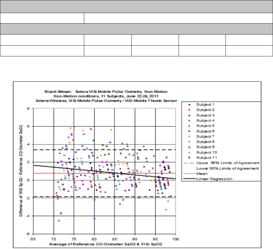
Vital Sign Measurements
167
The table below shows Arms values measured using the ViSi Mobile Thumb Sensor (Model 92-10020) with
the ViSi Mobile Monitoring System in a clinical study:
Note: Test subjects were healthy, in an age range from 21 to 45 years (7 males and 4 females), with
a wide range of skin pigmentation.
Validation Data (per ISO 9919)
Age of Volunteers 18 - 45
SpO2 Accuracy (No Motion)
SpO2 Range 70-100% 90-100% 80-90% 70-80%
Accuracy (Arms) - No Motion 1.9 1.2 1.9 2.4
Bland-Altman: ViSi Mobile Pulse Oximetry
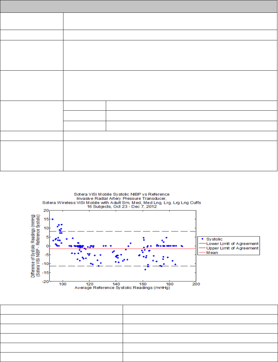
Vital Sign Measurements
168
10.2.4 Non-Invasive Blood Pressure (NIBP)
Non-Invasive Blood Pressure (NIBP)
Normative Reference ISO 81060-2: Non-invasive Sphygmomanometers - Part 2: Clinical validation of
automated measurement type.
Principle of Operation Oscillometry
Systolic Range: 60 to 240 mmHg
Accuracy: Mean error of less than ± 5 mmHg and a std. dev. of ≤ 8 mmHg
Resolution: 1 mmHg
Diastolic Range: 40 to 160 mmHg
Accuracy: Mean error of less than ± 5 mmHg and a std. dev. of ≤ 8 mmHg
Resolution: 1 mmHg
Mean Arterial Pressure Range: 50 to 185 mmHg
Accuracy: Mean error of less than ±5 mmHg and a std. dev. of ≤ 8 mmHg
Resolution: 1 mmHg
Pulse Rate Accuracy (NIBP) <3 BPM
Validation Study Invasive blood pressure (radial artery) reference
Number of subjects: 16
Subject Age Range: 19-48
Sample Size: 152 data points
Mean: -1.65 mmHg
Standard Deviation: 5.01 mmHg
Upper 95% Limits of Agreement (+1.96 SD): 8.2 mmHg
Lower 95% Limits of Agreement (-1.96 SD): -11.5 mmHg
Systolic Bland Altman Analysis (NIBP)
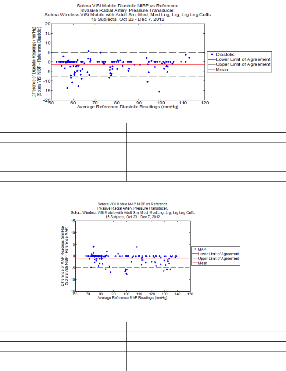
Vital Sign Measurements
169
Sample Size: 152 data points
Mean: -1.49 mmHg
Standard Deviation: 3.22 mmHg
Upper 95% Limits of Agreement (+1.96 SD): 4.8 mmHg
Lower 95% Limits of Agreement (-1.96 SD): -7.8 mmHg
Sample Size: 152 data points
Mean: -0.91 mmHg
Standard Deviation: 2.04 mmHg
Upper 95% Limits of Agreement (+1.96 SD): 3.1 mmHg
Lower 95% Limits of Agreement (-1.96 SD): -4.9 mmHg
Diastolic Bland Altman Analysis (NIBP)
Mean Arterial Pressure Bland Altman Analysis (NIBP)

Vital Sign Measurements
170
10.2.5 Continuous Non-Invasive Blood Pressure (cNIBP)
cNIBP Clinical Study Results
Sotera ViSi cNIBP vs. Reference Invasive Radial Artery Transducer (n=15 subjects)
Continuous Non-Invasive Blood Pressure (cNIBP)
Normative Reference ISO 81060-2: Non-invasive Sphygmomanometers - Part 2: Clinical validation of
automated measurement type.
Principle of Operation cNIBP is based on the relationship between blood pressure and the time it takes a pulse
that originates from a cardiac contraction to arrive at a peripheral location.
Display Update Continuous blood pressure is displayed based on averaging PAT calculations from the
previous 60 seconds and updating the display every 3 seconds.
Systolic Range: 60 to 240 mmHg
Accuracya,b:
a. ViSi Mobile Monitoring System accuracy claim is not met when the subject is inclined more than 30
degrees from horizontal.
b. The accuracy and precision of the cNIBP measurement met ISO 81060-2 requirements for the first 2.5
hours of testing.
Mean error of ≤ ± 5 mmHg and a std.dev. of ≤ 8 mmHg
Resolution: 1 mmHg
Diastolic Range: 40 to 160 mmHg
Accuracya,b:Mean error of ≤ ± 5 mmHg and a std.dev. of ≤ 8 mmHg
Resolution: 1 mmHg
Mean Arterial Pressure
(MAP)
Range: 50 to 185 mmHg
Accuracya,b:Mean error of ≤ ± 5 mmHg and a std.dev. of ≤ 8 mmHg
Resolution: 1 mmHg
Validation Study Invasive blood pressure (radial artery) reference
Number of subjects: 15
Subject age range: 19-48 years
Arm circumference range tested: 21-38 cm
Subject Position Supine 30o60oOverall
Systolic Bias -1.61 -4.77 -7.36 -1.88
Std. Dev. 5.69 7.87 9.97 6.17
Diastolic Bias -1.33 -3.97 -8.31 -1.65
Std. Dev. 3.16 4.49 6.07 3.62
MAP Bias -0.33 -3.01 -7.23 -0.67
Std. Dev. 3.36 5.37 6.67 3.86
Data Points 47,572 1,774 1,724 54,179
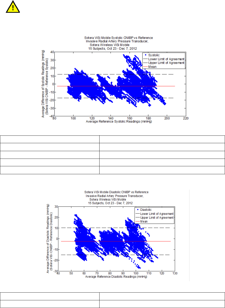
Vital Sign Measurements
171
Changes in posture and arm height can affect ViSi cNIBP accuracy. If the
cNIBP measurement is questionable, retake the measurement. Ideally
recalibrate in the same position as the initial calibration.
Sample Size: 54,179 data points
Mean: -1.88 mmHg
Standard Deviation: 6.17 mmHg
Upper 95% Limits of Agreement (+1.96 SD): 10.2 mmHg
Upper 95% Limits of Agreement (-1.96 SD): -14.0 mmHg
Sample Size: 54,179 data points
Mean: -1.65 mmHg
Systolic Bland Altman Analysis (cNIBP)
Diastolic Bland Altman Analysis (cNIBP)
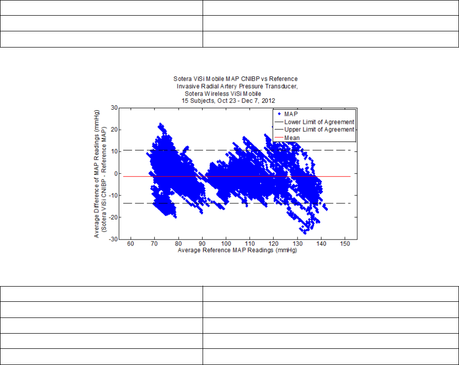
Vital Sign Measurements
172
Standard Deviation: 3.62 mmHg
Upper 95% Limits of Agreement (+1.96 SD): 5.4 mmHg
Upper 95% Limits of Agreement (-1.96 SD): -8.7 mmHg
Sample Size: 54,179 data points
Mean: -0.67 mmHg
Standard Deviation: 3.86 mmHg
Upper 95% Limits of Agreement (+1.96 SD): 6.9 mmHg
Upper 95% Limits of Agreement (-1.96 SD): -8.2 mmHg
MAP Bland Altman Analysis

Vital Sign Measurements
173
10.2.6 Skin Temperature
Note: The above skin temperatures have not been evaluated for correlation to core temperatures.
Temperature
Scale oCoF
Range / Accuracy
(measurement at
approximately 102 kPa
/ 768 mmHg)
Range Accuracy Range Accuracy
0o - 19.9o±0.3o 32o - 67.9o±0.5o
20o - 24.9o±0.3o68o - 76.9o±0.5o
25o - 35.9o±0.2o77o - 96.7o±0.3o
36o - 39.9o±0.1o96.8o - 103.9o±0.2o
40o - 41.9o±0.2o104o - 107.5o±0.3o
Resolution ± 0.1o± 0.1o
Transient Response < 6 min (25o - 37o) < 6 min (77o - 98.6o)

Physical Components
174
10.3 Physical Components
10.3.1 ViSi Mobile Monitor
Wireless Communications / Radio
ViSi Mobile Monitor
Physical Characteristics Dimensions 2.59 cm H x 4.85 cm W x 9.35 cm L
1.02 in. H x 1.91 in. W x 3.68 in. L
exclusive of connectors and Wrist Cradle
Weight 110 g / 3.92 oz
Monitor Display OLED, 160 x 128 pixels, full color
Audio Alarm annunciation, QRS, self-test
Waveforms One waveform, user selectable
Aspect Ratio: 0.4 Sec/mV
Scaled equivalent to 25 mm/sec sweep speed
Respiration waveform scaled equivalent to 6.25
mm/sec sweep speed
Battery Operating Time > 12 hours
Fuel Charge Display Battery Symbol
Charge Level with Full Indication
Charge Time Less than 4 hours
Battery Type Li-Ion, 3.7 V., 2000 mAh, single cell
Maximum Temperature 45oC / 113oF
Refer to IEC 60601-1:2005 (Section 11)
Cleaning / Disinfecting Liquid Ingress Rating IPX7
During cleaning cycle only, not during monitoring
Solutions / Compounds • Isopropyl alcohol (IPA)
• Detergent (Alconox)
Wireless Communications
Frequency 2.412 - 2.462 GHz
Protocol 802.11 b/g/n
Modulation DSSS, OFDM, DBPSK, DQPSK, CCK, 16-QAM and 64-QAM
Security WPA2 / PSK, AES
Power Output (max) 802.11 b: 15.8 dBm (38.3 mW)
802.11 g: 12.9 dBm (19.5 mW)
802.11 n: 11.8 dBm (15.1 mW)
Data Throughput < 30 KBps

Physical Components
175
Mode Plugs
Other RF radiating devices (such as high powered RFID readers and Bluetooth
devices) that are in close proximity with the ViSi Mobile Monitor may interfere with the
Monitor’s wireless communications. During such interference, the Monitor continues
to monitor and will alarm locally. If wireless communication is affected when using the
Monitor in close proximity with another RF radiating device, move the other device
away from the Monitor or discontinue use of the other device.If you have any
concerns regarding a cyber security breach or vulnerability, contact Sotera Wireless,
Inc. or an authorized Sotera Wireless, Inc. representative in your area.
Mode Plugs
Shipping Plug Turns device off completely
Locking Plug Secures Monitor into Wrist Cradle
Bio Med Modea
a. The Bio Med Mode is only available to hospital Bio Meds.
Enables configuration and test functions

Physical Components
176
10.3.2 ViSi Mobile Chest Sensor
ViSi Mobile Chest Sensor
Mechanical Complies with EC53
Weight
(5 lead-wire / 3 lead-wire)
72 g / 62 g (2.54 oz. / 2.19 oz.)
Operating Temperature 0 - 40oC / 32oF - 104oF
Refer to IEC 60601-1:2005 (Section 11)
Cleaning / Disinfecting Liquid Ingress Rating IPX7
During cleaning cycle only, not during monitoring
Solutions / Compounds • Isopropyl alcohol (IPA)
• Detergent (Alconox)

Physical Components
177
10.3.3 ViSi Mobile Cuff Module
ViSi Mobile Cuff Module
Physical Characteristics Dimensions 3.10 cm H x 4.85 cm W x 12.19 cm L
(1.22 in. H x 1.91 in. W x 4.80 in. L)
exclusive of cable
Weight 157 g (5.54 oz)
Battery Operating Time > 30 cuff inflations or 24 hrs, whichever occurs
first
Charge Display Status Eight LEDs: Six levels of Green, Yellow, Red
Charge Time < 4 hours
Battery Type Battery Pack, Li-Ion, 2000 mAh
Maximum Temperature 45oC / 113oF
Refer to IEC 60601-1:2005 (Section 11)
Cuff Sizes
Arm Circumference (cm)
Small 20 – 26
Medium 25 – 34
Medium+ 25 – 34
Large 32 – 43
Large+ 32 – 43
Cleaning / Disinfecting Liquid Ingress Rating IPX0
Solutions / Compounds • Isopropyl alcohol (IPA)
• Detergent (Alconox)
When the ViSi Mobile Cuff Module is connected to the other ViSi Mobile
Components, the entire system has an ingress protection rating of IPX0.

Physical Components
178
10.3.4 ViSi Mobile Thumb Sensor
ViSi Mobile Thumb Sensor
Cleaning / Disinfecting Liquid Ingress Rating IPX7
During cleaning cycle only, not during monitoring
Solutions / Compounds • Isopropyl alcohol (IPA)
• Detergent (Alconox)

Physical Components
179
10.3.5 ViSi Mobile Charger - 8 Bay
10.3.6 ViSi Mobile Charger - 2 Bay
ViSi Mobile Charger
Physical Characteristics Dimensions 7.7 cm x 46.3 cm x 5.9 cm
(3.0 in x 18.2 in x 2.3 in)
Weight 0.7 kg (1.5 lb)
AC Mains AC Line Voltage 100-240 V, 50-60 Hz
Power (all bays charging) 75 W
Cleaning / Disinfecting Liquid Ingress Rating IPX0
Solutions / Compounds • Isopropyl alcohol (IPA)
• Detergent (Alconox)
ViSi Mobile Charger
Physical Characteristics Dimensions 7.7 cm x 12.9 cm x 5.9 cm
(3.0 in x 5.1 in x 2.3 in)
Weight 0.25 kg (0.6 lb)
AC Mains AC Line Voltage 100-240 V, 50-60 Hz
Power (all bays charging) 30 W
Cleaning / Disinfecting Liquid Ingress Rating IPX0
Solutions / Compounds • Isopropyl alcohol (IPA)
• Detergent (Alconox)

Physical Components
180
10.3.7 ViSi Mobile Power Pack (Optional Accessory)
ViSi Power Pack Cradle
ViSi Power Pack
Physical Characteristics Dimensions 3.13 cm H x 4.87 cm W x 12.19 cm L
(1.23 in. H x 1.91 in. W x 4.80 in. L)
Cable Length 3 to 5 ft.
Weight 172 g (6.07 oz.)
Battery Operating Time minimum 24 hrs
Charge Display Status Eight LEDs: Six levels of Green, Yellow, Red
Charge Time < 6 hours
Battery Type Battery Pack, Li-Ion, 2000 mAh
Maximum Temperature 50oC / 122oF
Refer to IEC 60601-1:2005 (Section 11 for
equipment not intended to contact patient)
Cleaning / Disinfecting Liquid Ingress Rating IPX0
Solutions / Compounds • % Isopropyl alcohol (IPA)
• Detergent (Alconox)
ViSi Power Pack Cradle
Physical Characteristics Dimensions 4.87 cm H x 9.5 cm W x 10.0 cm L
(1.91 in H x 3.74 in W x 3.93 in L)
Weight Without clamp: 91.3 g (3.22 oz.)
With clamp 0.53 kg (1.17 lb.)
Cleaning / Disinfecting Liquid Ingress Rating IPX0
Solutions / Compounds • Isopropyl alcohol (IPA)
• Detergent (Alconox)

Physical Components
181
10.3.8 ViSi Mobile Appliance
In the ViSi Mobile Monitoring System, data is captured in the ViSi Mobile Appliance, which acts as an
enterprise hub. The Appliance is dedicated hardware installed in the IT datacenter for secure network
connectivity and emergency power backup. For more information on the ViSi Mobile Appliance, see the
ViSi Mobile Monitoring System Technical Reference Manual.
ViSi Mobile Appliance
Server Configuration Single 1u, redundant hardware and internal RAID 10, dedicated hardware.
Processor Single Intel Xeon 5620
2.4 GHz (or equivalent CPU)
8 GB memory
Storage Server contains at a minimum 4 x 500 GB 7200 RPM hard drives in RAID 10
array
Operating System Note: SUSE Linux Enterprise Server (Version 11, Patch Level 2)
Network Requirements Static IP address or DHCP reservation required
Multicast configuration on network backbone devices
Dimensions
(Single Appliance, may vary)
H: 43.0 cm x W: 43.4 cm x L: 62.7 cm (w/o ear, w/o bezel)
H: 1.7 in x W: 17.1 in x L: 24.7 in
Weight
(Single Appliance)
35.02 lb (15.9 kg)
(Maximum configuration weight)
Power Requirements
(Single Appliance)
100-240 VAC, 50-60 Hz, 7 A - 3.5 A w/ redundant power supply
Backup Power Requirement
(Full System)
Customer supplied Uninterruptable Power Supply and Hospital Emergency
Power recommended.

Physical Components
182
10.3.9 ViSi Mobile Remote Viewer
Note: Sotera Wireless, Inc. recommends installation of Trend Micro anti-virus software on
Windows platforms. Anti-virus software is not installed on the ViSi Mobile Monitor.
Note: For printing capability, Sotera Wireless, Inc. recommends connecting a printer directly to
the ViSi Mobile Remote Viewer or to an in-network printer via an IP address. Sotera
Wireless, Inc. does not support additional configurations.
ViSi Mobile Remote Viewer (Desktop PC with Touchscreen Display)
No. of Patients per Remote Viewer Maximum 32
Display 23 in display / 1920 x 1080 resolution
(screen is touch sensitive to issue commands alternative to mouse/keyboard)
Processor Intel i5 2400 CPU 4 Core
3.10 GHz
4 GB Memory
Storage One 500 GB 7200 RPM SATA
Operating Systems Microsoft® Windows® 7 Professional (version 6.1) x64 Bit SP1
Network Requirements Ethernet Connection, DHCP
Dimensions H: 45.0 cm x W: 58.5 cm x D: 10.3 cm
H: 17.7 in x W: 23.0 in x D: 4.1 in
Weight 26.7 lb (12.1 kg)
Power Requirements AC/DC Adapter
Input: 100-240 V ~3.5 A, 50-60 Hz
Output to Viewer: 19.5 V / 11.8 A
Backup Power Requirement Customer supplied Uninterruptable Power Supply and Hospital Emergency
Power recommended.

Physical Components
183
10.3.10 Customer Network
Wireless Network
Wireless Network Standard IEEE 802.11b/g/n
Recommended Channels 1, 6, 11
Network Latency < 150 ms
Wireless Network Security Support WPA2-PSK
Minimum Receiver Sensitivity -65 dBm (edge coverage)
Wireless access point cell overlap 15-20%
Signal-to-Noise Ratio 25 dB
Packet loss 6%
SSID Dedicated or shared with other medical devices
Wired Network
Appliance (Server) Requires static IP Address
Network availability >99.9%

Alarms / Alerts Annunciation
184
10.4 Alarms / Alerts Annunciation
Note: An “Annunciation Delay” is the time that an alarm system deliberately delays the alarm
annunciation (audibly and visually) to ensure clinical relevance of the detected alarming
condition. Within the tables below, see column “Annunciation Delay” for the pre-defined
periods of time.
10.4.1 Physiological Alarms (Alarms)
Visual Display
The following table outlines the visual display when alarms are in progress:
Audio Tones
The following table outlines the audio tones when alarms are in progress:
Alarm Limits and Delays (factory default settings).
Severity Indicator Attributes Toggle / Flash Speed Duty Cycle
High Priority Red 1.5 Hz 50% ON
Life-Threatening Priority Red / White 1.5 Hz 50% ON
Severity Melodya
a. Melodies are defined as musical notes.
Volum
e
[dB]
Frequency
(fo) [Hz] Duration
(td) [ms] Spacing
(ts) [ms] 5th-6th
[s] Inter-Burst
(tb) [s]
Life Threatening b5.b5.b5..b5.b5 78 987.767 100 50 0.35 2.5
High b5.b5.b5..b5.b5 78 987.767 200 100 0.35 5
Vital Sign Lower Limit Upper Limit Annunciation
Delaya
Care Unit Patient Patient Care Unit (seconds)
Critical Low HR (BPM) 18 18 N/A N/A 5
Heart Rate (BPM) 30 30 150 200 5
Pulse Rate (BPM) 30 30 150 200 30
BP Systolic (mmHg) 70 OFF 190 240 120
BP Diastolic (mmHg) 40 OFF OFF 150 120
BP MAP (mmHg) 60 65 OFF 170 90
Respiration (BR/MIN) 4 4 35 40 120
SpO2 (%) 85 85 N/A N/A 60
Skin Temperature N/A N/A N/A N/A N/A
Alarms / Alerts Annunciation
185
a. When measuring blood pressure as a 1-time measurement or at automatic intervals, there will
be no annunciation delay.

Alarms / Alerts Annunciation
186
Battery Alarms
No Pulse Detected Alarms Limit Annunciation Delay
When Thumb Sensor is primary source No Pulse No delay
When Cuff Module is primary source No Pulse No delay
Battery Alarms Limit Annunciation Delay
Monitor
Monitoring Mode 45oC (113oF) No delay
In the Charger 45oC (113oF) No delay
Not monitoring / Not in the Charger 45oC (113oF) No delay
Cuff
Module
Connected to the Monitor 45oC (113oF) No delay
In the Charger 45oC (113oF) No delay
Not monitoring / Not in the Charger 45oC (113oF) No delay
Power Pack
Connected to the Monitor 50oC (122oF) No delay
In the Charger 50oC (122oF) No delay
Not monitoring / Not in the Charger 50oC (122oF) No delay

Alarms / Alerts Annunciation
187
10.4.2 Equipment Alarms (Alerts)
Visual Display
The following table outlines the visual display when alerts are in progress:
Audio Tones
The following table outlines the audio tones when alerts are in progress:
Note: There are no audio tones associated with low severity alerts.
Alarm Limits and Delays (factory default settings)
Severity Indicator Attributes Toggle / Flash Speed Duty Cycle
All Severities Cyan (Blue) Constant (ON) 100% ON
Severity Melodya
a. Melodies are defined as musical notes.
Volume
[dB] Frequency
(fo) [Hz] Duration
(td) [ms] Spacing
(ts) [ms] Inter-Burst
(tb) [s]
High e5.c5 68/63 659.255, 523.251 250 250 15
Chest Sensor Alerts Limit(if applicable) Audible Alert Annunciation Delay
ECG Lead Failure N/A No No delay
All ECG Lead Failure N/A No No delay
Chest Sensor Disconnected N/A No No delay
General Fault Detected N/A No No delay
Multiple Connections N/A No No delay
Temperature Sensor Fault N/A No No delay
Accelerometer Fault - Chest Module N/A No No delay
Accelerometer Fault - Upper Arm N/A No No delay
Thumb Sensor Alerts Limit
(if applicable) Audible Alert Annunciation Delay
(in seconds)
Thumb Sensor Off N/A No < 30
Thumb Sensor Disconnected N/A No No delay
Cuff Module Alerts Limit
(if applicable) Audible Alert Annunciation Delay
(in seconds)
Low Battery 4% to 10% No No delay
Battery Empty < 4% No No delay

Alarms / Alerts Annunciation
188
Check Cuff N/A No No delay
Cuff Occluded N/A No No delay
NIBP Unobtainable N/A No No delay
Invalid Software Loaded N/A No No delay
Pressure Accuracy Fault N/A No No delay
General Fault Detected N/A No No delay
Pressure Exceeded 300mmHg Yes No delay
Multiple Connections N/A No No delay
cNIBP Alerts Limit
(if applicable) Audible Alert Annunciation Delay
(in seconds)
Calibration Failed N/A N/A No delay
Calibrate cNIBP N/A N/A No delay
Hold Still N/A N/A No delay
Wrist Monitor Alerts Limit
(if applicable) Audible Alert Annunciation Delay
(in seconds)
Calibrate cNIBP N/A N/A No delay
Low Battery 3 hours No No delay
Critical Low Battery 1 hour No No delay
Too Low to Monitor 10 minutes No No delay
Invalid Plug Connected N/A Yes No delay
Audio System Failure N/A No No delay
Wireless Radio Failure N/A No No delay
All Sensors Disconnected N/A No No delay
Accelerometer Failure N/A No No delay
Shock Hazard N/A Yes No delay
Patient Tampering
(number of incorrect pin code entries)
5 invalid pin codes No No delay
ViSi Power Pack Alerts Description of
Annunciation Audible Alert Annunciation Delay
(in seconds)
Power Pack Connected 1 Beep Yes No delay
Power Pack Disconnected 1 Beep Yes No delay
Power Pack Low Battery Red LED Flashes (<
4% charge)
Yellow LED Flashes
(4%-10% charge)
No No delay
Cuff Module Alerts Limit
(if applicable) Audible Alert Annunciation Delay
(in seconds)

Environmental Conditions
189
10.5 Environmental Conditions
Battery Temp. Exceeds Limit Red LED Solid and
Continuous Beep
Tone
Yes No delay
Battery Current. Exceeds Limit Red LED Solid and
Continuous Beep
Tone
Yes No delay
Battery Pack Fault Message on ViSi
Monitor
Beep/Buzz on
Power Pack ONLY
No delay
Environmental Conditions for all ViSi Mobile Components
(Monitor, Cuff Module, Chest Sensor, Cuff, Thumb Sensor, Power Pack)
Condition Storage
(Packaged / Unpacked) Operating
(Unpackaged)
Temperature -20oC to +55oC (50oC for NIBP)
-4oF to +131oF (122oF for NIBP)
0oC to +40oC / 32oF to +122oF
Battery Charger: 0oC to +40oC
Humidity 15% to 95% non-condensing
(90% for NIBP)
10% to 95% non-condensing
(90% for NIBP)
(15% to 95% non-condensing for Power
Pack)
Atmospheric Pressure
Range
107 kPa to 50 kPa
803 mmHg to 375 mmHg
1.06 atm to 0.49 atm
107 kPa to 70 kPa
803 mmHg to 525 mmHg
1.06 atm to 0.69 atm
The ViSi Mobile Monitoring System may not perform to specification if
stored or shipped outside the specified temperature range.
ViSi Power Pack Alerts Description of
Annunciation Audible Alert Annunciation Delay
(in seconds)
Compliances
190
10.6 Compliances
Observe any national regulations on the qualification of the testing personnel and suitable measuring and
testing facilities. See “User/Preventative Maintenance” on page 105. for a list of required tests.
10.6.1 Federal Communications Commission (FCC)
The equipment device complies with Part 15 of the FCC Rules. Operation is subject to the following two
conditions: (1) This device may not cause harmful interference, and (2) This device must accept any
interference received including interference that may cause undesired operation.
Changes or modifications not expressly approved by Sotera Wireless, Inc. could void the user’s authority
to operate the equipment. Manufacturer is not responsible for any radio or TV interference caused by
unauthorized modifications to this equipment.
This equipment has been tested and found to comply with the limits for a Class B digital device, pursuant
to Part 15 of the FCC Rules. These limits are designed to provide reasonable protection against harmful
interference in a residential installation. This equipment generates, uses and can radiate radio frequency
energy and, if not installed and used in accordance with the instructions, may cause harmful interference to
radio communications. However, there is no guarantee that interference will not occur in a particular
installation. If this equipment does cause harmful interference to radio or television reception, which can
be determined by turning the equipment off and on, the user is encouraged to try to correct the interference
by one or more of the following measures:
• Reorient or relocate the receiving antenna
• Increase the separation between the equipment and receiver
• Connect the equipment into an outlet on a circuit different from that to which the receiver is
connected
• Consult the dealer or an experienced radio/TV technician for help
This device complies with Industry Canada license-exempt RSS standard(s). Operation is subject to the
following two conditions: (1) this device may not cause interference, and (2) this device must accept any
interference, including interference that may cause undesired operation of the device.
Le présent appareil est conforme aux CNR d'Industrie Canada applicables aux appareils radio exempts de
licence. L'exploitation est autorisée aux deux conditions suivantes : (1) l'appareil ne doit pas produire de
brouillage, et (2) l'utilisateur de l'appareil doit accepter tout brouillage radioélectrique subi, même si le
brouillage est susceptible d'en compromettre le fonctionnement.
Class B digital device notice / “CAN ICES-3 (B)/NMB-3(B)”.
This equipment complies with the FCC/IC radiation exposure limits set fourth for portable transmitting
devices operation in a controlled environment. End users must follow the specific operating instructions to
satisfy RF exposure compliance.
The equipment should only be used where there is normally at least 22.651mm separation between the
antenna and all person/user.
This transmitter must not be co-located or operated in conjunction with any other antenna or transmitter.
Any changes or modifications not expressly approved by the party responsible for compliance could void
the user’s authority to operate this equipment.

Compliances
191
10.6.2 Electromagnetic Compatibility (EMC) Specifications
Take special precautions regarding electromagnetic compatibility (EMC) when using medical electrical
equipment. Operate your monitoring equipment according to the EMC information provided in this
manual. Portable and mobile radio frequency (RF) communications equipment can affect medical
electrical equipment.
Accessories Compliant with EMC Standards
All accessories (e.g. ViSi Mobile Charger) comply with either IEC 60601-1-2 or IEC 60950-1.
Consult your Biomed department or vendors for assistance in identifying
EMC compliance status of other medical devices when using the ViSi
Mobile Monitoring System or Power Pack.
Using accessories other than those specified may result in increased
electromagnetic emission or decreased electromagnetic immunity of the
monitoring equipment.

Compliances
192
10.6.3 Electromagnetic Emissions
The ViSi Mobile Monitor is suitable for use in the electromagnetic environment specified in the table
below. Ensure that the Monitor is used in such an environment.
Emissions Test Compliance Avoiding Electromagnetic Interference
Radio Frequency (RF) emissions Group 1 The ViSi Mobile Monitor uses RF energy only for
its internal functiona. Therefore, its RF emissions
are very low and are not likely to cause any
interference in nearby electronic equipment.
a. The battery operated ViSi Mobile Monitor contains a 2.4 GHz DSSS transmitter for the purpose of wire-
less communication. The radio is excluded from the EMC requirements of IEC 60601-1-2, but should be
considered when addressing possible interference issues between this and other devices.
RF emissions CISPR 11 Class A The ViSi Mobile Monitor is suitable for use in all
establishments other than domestic and those
directly connected to the public low-voltage
supply network that supplies buildings used for
domestic purposes.
Harmonic emissions IEC 61000-3-2 N/A
Voltage fluctuations IEC 61000-3-3 N/A

Compliances
193
10.6.4 Electromagnetic Immunity
The ViSi Mobile Monitor is suitable for use in specified electromagnetic environments. The user must
ensure that it is used in the appropriate environment as described below.
In the above table, UT (Unit in Test) is the ViSi Mobile Monitoring System.
Immunity Test IEC 60601-1-2 Electromagnetic
Environment Guidance
Test Level Compliance Level
Electrostatic
discharge (ESD)
IEC 61000-4-2
±6 kV contact
±8 kV air
±6 kV contact
±8 kV air
Floors should be wood,
concrete, or ceramic tile. If
floors are covered with
synthetic material, the
relative humidity should be
at least 30%.
Electrical fast
transient / burst
IEC 61000-4-4
±2 kV for power supply lines
±1 kV for input/output lines
±2 kV for power supply lines
±1 kV for input/output lines
Mains power quality should
be that of a typical medical
and/or hospital environment.
Surge
IEC61000-4-5
±1 kV differential mode
±2 kV common mode
±1 kV differential mode
±2 kV common mode
Mains power quality should
be that of a typical medical
and/or hospital environment.
Voltage dips,
short
interruptions and
voltage
variations on
power supply
input lines
IEC 61000-4-11
<5% UT
(>95% dip in UT) for 0.5
cycles
<5% UT
(>95% dip in UT) for 0.5
cycles
40% UT
(60% dip in UT) for 5 cycles
40% UT
(60% dip in UT) for 5 cycles
70% UT
(30% dip in UT) for 25
cycles
70% UT
(30% dip in UT) for 25
cycles
<5% UT
(>95% dip in UT) for 5 sec
<5% UT
(>95% dip in UT) for 5 sec
Power frequency
(50/60Hz)
magnetic field
IEC 61000-4-8
3 A/m 3 A/m Power frequency magnetic
fields should be at levels
characteristic of a typical
location in a typical hospital
environment.
Compliances
194
10.6.5 Recommended Separation Distance
Portable and mobile RF communications equipment should be used no closer to any part of the ViSi
Mobile Monitor, including cables, than the recommended separation distance calculated from the equation
appropriate for the frequency of the transmitter.
Field strengths from fixed RF transmitters, as determined by an electromagnetic site survey, should be less
than the compliance level in each frequency range.
In the following table, P is the maximum output power rating of the transmitter in watts (W) according to
the transmitter manufacturer and d is the recommended separation distance in meters (m).
Field strengths from fixed transmitters, such as base stations for radio (cellular, cordless) telephones and
land mobile radios, amateur radio, AM and FM radio broadcast and TV broadcast cannot be predicted
theoretically with accuracy. To access the electromagnetic environment due to fixed RF transmitters, an
electromagnetic site survey should be considered. If the measured field strength in the location in which
the ViSi Mobile Monitor is used exceeds the applicable RF compliance level above, the Monitor should be
observed to verify normal operation. If abnormal performance is observed, additional measures may be
necessary, such as reorienting or relocating the Monitor.
The ViSi Mobile Monitor may be temporarily interrupted by UHF RFID
Systems (860-960MHz).
2-way radios may cause waveform distortion when placed within 1 foot of
the ViSi Mobile Monitor.
Some brands of television may cause temporary waveform distortion and
data loss when placed within 6 feet of the ViSi Mobile Monitor.
Interference may occur in the vicinity of equipment marked with this symbol:
Immunity Test IEC 60601-1-2
Test Level ViSi Mobile Monitoring
System Compliance Level Electromagnetic Environment
Guidance
Conducted RF
IEC 61000-4-6
3 VRMS
150 kHz to 80 MHz
3 VRMS Recommended separation distance:
d = 1.2P
Radiated RF
IEC 61000-4-3
3 V/m
80 MHz to 2.5 GHz
3 V/m Recommended separation distance:
80 MHz to 800 MHz
80 MHz to 800 MHz
d = 3.5P
800 MHz to 2.5 GHz
d = 2.3P
2.0 to 2.3 GHz for short radio
d = 7.0P

Compliances
195
These guidelines may not apply in all situations. Electromagnetic propagation is affected by absorption
and reflection from structures, objects and people.
From Portable and Mobile RF Communication Equipment
The ViSi Mobile Monitor is intended for use in an electromagnetic environment in which radiated RF
disturbances are controlled. The customer or user of the Monitor can help prevent electromagnetic
interference by maintaining a minimum distance between portable and mobile RF communications
equipment and the Monitor as recommended below, according to the maximum output power of the
communications equipment.
In the following table, P is the maximum power output rating of the transmitter in watts (W) according to
the transmitter manufacturer and d is the recommended separation distance in meters (m).
Electrosurgery Interference/Defibrillation/Electrostatic Discharge
The equipment returns to the previous operating mode within 10 seconds without loss of any stored data.
Measurement accuracy may be temporarily decreased while performing electrosurgery or defibrillation.
This does not affect patient or equipment safety. Do not expose the equipment to x-ray or strong magnetic
fields (MRI).
Fast Transients/Bursts
The equipment will return to the previous operating mode within 30 seconds without loss of any stored
data.
Frequency 150 kHZ to 80 MHz 80 MHz to 800 MHz 800 MHz to 2.5 GHz
Equation d = 1.2Pd=1.2Pd=2.3P
Rated max. output
power of transmitter
Separation Distance Separation Distance Separation Distance
(m) (ft) (m) (ft) (m) (ft)
0.01 W 0.1 0.4 0.1 0.4 0.2 0.8
0.1 W 0.4 1.2 0.4 1.2 0.7 2.4
1 W 1.3 3.9 1.3 3.9 2.3 7.5
10 W 3.8 12.4 3.8 12.4 7.3 23.9
100 W 12.0 39.4 12.0 39.4 23.0 75.5

Compliances
196
10.6.6 Standards
Agency Compliances
• CAN/CSA C22.2 No 60601-1, Part 1: General requirements for basic safety and essential performance
• IEC 60601-1:2005 Medical electrical equipment - Part 1: General requirements for safety (EN 60601-
1:2006)
• IEC 60601-1-2:2007, Med. Elect. Equipment – Part 1-2: General requirements for safety – Collateral stan-
dard: EMC – Req. and tests.
• IEC 60601-1-6:2010, Medical electrical equipment – Part 1-6: General requirements – Collateral standard:
Usability.
• IEC 60601-1-8:2012, Medical electrical equipment – Part 1-8: Gen. req. – Col. Std. Gen. requirements,
tests and guidance for alarm systems
• IEC 60601-2-27:2011, Medical electrical equipment, Part 2-27: Particular requirements or the safety,
including essential performance, of ECG monitoring equipment (except 208.6.6.2.103).
• IEC 80601-2-30:2009, Medical electrical equipment – Part 2-30: Particular requirements for the safety,
including essential performance, of auto. cycling non-invasive BP monitoring equipment.
• IEC 60601-2-49:2011, Medical electrical equipment - Part 2-49: Particular requirements for the basic
safety and essential performance of multi-function patient monitoring equipment.
• ISO 80601-2-61:2011, Medical electrical equipment - Particular requirements for the basic safety and
essential performance of pulse oximeter equipment for medical use.
• IEC 62304:2006, Medical device software – Software life cycle processes
• IEC 62366:2007, Medical devices – Application of usability engineering to medical devices.

Wireless Network Risk Mitigation
197
10.7 Wireless Network Risk Mitigation
Reference: ISO 80001-1
ViSi Mobile System utilizes the Responsible Organization’s wireless IT network to communicate between
individual ViSi Mobile Monitors connected to patients and the ViSi Appliance. Physiologic data and
alarms originating from the ViSi Mobile Monitors are transmitted over the IT network to the ViSi Mobile
Remote Viewer where supplemental alarm notification occurs. Reliability of the IT network is essential in
ensuring the supplementary alarm notification meets the intended use.
10.7.1 Risk Analysis Summary
• The ViSi Mobile Monitors are the source of all alarms and alerts.
• The ViSi Mobile Remote Viewer provides a supplemental alarm notification. When connectivity
is present audio alarms are deferred to the ViSi Mobile Remote Viewer.
• In the event that network connectivity is lost, all audio alarms are annunciated at the ViSi Mobile
Monitors. A connectivity lost alert is annunciated at the ViSi Mobile Remote Viewer.
10.7.2 Residual Risks
Loss of network connectivity will result in failure in supplemental alarm notification to the ViSi Appliance
and ViSi Mobile Remote Viewer. Management of this risk is the responsibility of the Responsible
Organization for the IT Network. This risk is minimized with the following mitigations:
Sotera Responsibilities
• Sotera Inc network assessment prior to installation.
• Sotera Inc verification that the Responsible Organization network meets ViSi Mobile System
connectivity requirements at the time of installation.
• Hand over protocol with all settings/configurations as installed and configured (Training)
Responsible Organization Responsibilities
• Conduct a risk assessment of the IT Network prior to installation and mitigate technical risk.
• Maintain backup and emergency power resources for ViSi System network components.
• Maintain network configuration post installation of the ViSi Mobile System.
Other RF radiating devices (such as high powered RFID readers and Bluetooth
devices) that are in close proximity with the ViSi Mobile Monitor may interfere with the
Monitor’s wireless communications. During such interference, the Monitor continues
to monitor and will alarm locally. If wireless communication is affected when using the
Monitor in close proximity with another RF radiating device, move the other device
away from the Monitor or discontinue use of the other device.If you have any
concerns regarding a cyber security breach or vulnerability, contact Sotera Wireless,
Inc. or an authorized Sotera Wireless, Inc. representative in your area.
Perform a risk assessment and verification before implementing a change or
modification to the IT infrastructure. Changes to IT network configurations can
compromise continuous vital signs monitoring and alarm delivery. on page 18
Wireless Network Risk Mitigation
198
Notify Sotera Wireless, Inc. prior to making modifications to the network, including configuration changes
that could potentially compromise the IT Network as verified at the initial installation of the ViSi System.
For support contact Sotera Wireless, Inc. or an authorized Sotera Wireless, Inc. representative in your area.
- Notes -
199
Appendix A - Alarm Summary
Patient Alarms
Life Threatening Alarms
Note: When the Cuff Module is in the Charger, the LED on the front of the Cuff Module will
display red.
Display Message Symbol(s) Alarm Summary Cause
CRITICAL LOW HR Critical Low Heart Rate Note: Patient’s heart rate is less than 18
BPM.
MONITOR TOO HOT Monitor - Battery Over-
Temperature Failure
• Battery in the Monitor has exceeded
a safe temperature.
• The Chest Module has exceeded a
safe temperature.
Return the Monitor and the Chest
Sensor to Sotera Wireless, Inc.
CUFF BATTERY
TEMP
Cuff Module - Battery
Over-Temperature
Failure
Battery in the Cuff Module has exceeded
a safe temperature.
Return the Cuff Module to Sotera
Wireless, Inc..
When the “Monitor Too Hot” alarm is in progress, the ViSi Mobile Monitor
and Chest Sensor should be removed from the patient immediately. Leaving
them on the patient for an extended period of time may lead to a skin burn.
When the “Cuff Battery Temp” alarm is in progress, the ViSi Mobile Cuff
Module should be removed from the patient immediately. Leaving it on the
patient for an extended period of time may lead to a skin burn.

Patient Alarms
200
High Alarms
Display Message Alarm Summary Cause
THUMB NO PULSE SpO2 Module - No Pulse
Detected
Unable to detect a pulse from the Thumb Sensor.
Thumb Sensor is the primary source of PR.
CUFF NO PULSE Cuff Module - No Pulse
Detected
Chest Sensor and Thumb Sensor are not connected.
Cuff Module is the only source of PR. Unable to
detect a pulse from the cuff inflation.
HIGH PULSE RATE High Pulse Rate Pulse rate exceeds the defined upper alarm limit.
LOW PULSE RATE Low Pulse Rate Pulse rate is less than the defined lower alarm limit
HIGH HEART RATE High Heart Rate Heart rate exceeds the defined upper alarm limit.
LOW HEART RATE Low Heart Rate Heart rate is less than the defined lower alarm
limit.
HIGH BP SYSTOLIC BP - High Systolic Systolic pressure exceeds the defined upper alarm
limit.
LOW BP SYSTOLIC BP - Low Systolic Systolic pressure is less than the defined lower
alarm limit.
HIGH BP DIASTOLIC BP - High Diastolic Diastolic pressure exceeds the defined upper alarm
limit.
LOW BP DIASTOLIC BP - Low Diastolic Diastolic pressure is less than the defined lower
alarm limit.
HIGH BP MAP BP - High MAP MAP pressure exceeds the defined upper alarm
limit.
LOW BP MAP BP - Low MAP MAP pressure exceeds the defined lower alarm
limit.
HIGH RESP High Respiration Respiration exceeds the defined upper alarm limit.
LOW RESP Low Respiration Respiration is less than the defined lower alarm
limit.
LOW SpO2Low SpO2SpO2 is less than the defined lower alarm limit.
Equipment Alerts
201
Equipment Alerts
ViSi Mobile Monitor Alerts
Display Message Symbol(s) Severity Cause Solution
AUDIO FAILURE Low Either the microphone or
the speaker on the Monitor
has failed.
Stop monitoring and replace
the Monitor.
Return the Monitor to Sotera
Wireless, Inc.
WIRELESS
RADIO
Low The wireless radio in the
Monitor is not transmitting.
Stop monitoring and replace
the Monitor.
Return the Monitor to Sotera
Wireless, Inc.
MONITOR
BATTERY
CRITICAL
Low Monitor battery charge is
critically low.
Replace the Monitor.
MONITOR
BATTERY LOW
Low Monitor battery charge is
low.
Prepare to replace the Monitor.
UNABLE TO
MONITOR
Low Battery in the Monitor is too
low to continue monitoring.
Replace the Monitor.
CONNECT TO
PATIENT
N/A Low A sensor has been
connected to the Monitor
but not yet applied to the
patient. No vital sign
measurement has been
detected.
Apply the sensor to the patient.
ACCEL
MONITOR
Low Unexpected error occurred
with the accelerometer in
the Monitor.
Replace the Monitor and return
it to Sotera Wireless, Inc.

Equipment Alerts
202
ViSi Mobile Chest Sensor and ECG Alerts
Display Message Severity Cause Solution
CHEST SENSOR Low The Chest Sensor is
disconnected from the Monitor
and not yet acknowledged by the
clinician.
Acknowledge the alert and remove
the Chest Sensor from the patient, or
reconnect the Chest Sensor to the
Monitor.
Low More than one Chest Sensor is
simultaneously connected to the
Monitor.
Remove the extra Chest Sensor(s)
from the Monitor.
CHEST FAULT Low Various failure modes related to
the Chest Sensor.
Replace the Chest Sensor and return
it to Sotera Wireless, Inc.
Low The Chest Sensor does not
contain the correct software.
Replace the Chest Sensor and return
it to your biomedical engineer.
ECG LEAD
(+ lead label)
Low One or more lead-wires have
failed or become disconnected
from the electrode(s).
Reconnect the ECG electrode, if
necessary.
Replace the ECG electrode, if
necessary.
ECG LEADS Low All ECG lead-wires have failed. Reconnect the lead-wires to the ECG
electrodes.
Replace the ECG electrodes if
necessary.
TEMPERATURE
FAULT
Low Unexpected error occurred with
the Temperature Sensor.
Replace the Chest Sensor and return
it to Sotera Wireless, Inc.
ACCEL. CHEST Low Unexpected error occurred with
the accelerometer in the Chest
Sensor.
Replace the Chest Sensor and return
it to Sotera Wireless, Inc.
ACCEL. UPPER
ARM
Low Unexpected error occurred with
the Upper Arm accelerometer.
Replace the Chest Sensor and return
it to Sotera Wireless, Inc.
Use all of the same type of high quality ECG electrodes on the patient.
Mixing ECG electrode types can adversely affect ECG monitoring.

Equipment Alerts
203
ViSi Mobile Thumb Sensor and SpO2 Alerts
ViSi Mobile Cuff Module and NIBP Alerts
Display Message Severity Cause Solution
THUMB SENSOR Low The Thumb Sensor has been
disconnected from the Monitor
and has not yet been
acknowledged by the clinician.
Acknowledge the alert, or reconnect
the Thumb Sensor to the Monitor.
THUMB SENSOR
OFF
Low The optical signal has been lost. Reposition the Thumb Sensor at the
base of the patient’s thumb. Replace
the Thumb Sensor.
Display Message Severity Cause Solution
CHECK CUFF Low An issue has been found with
the cuff during inflation
Check the connection between the
Cuff and the Cuff Module.
Check the Cuff for damage.
CUFF OCCLUDED Low Something is blocking the air
from being pumped into the
Cuff.
Check for a kinked hose. Check to
make sure that the connection
between the Cuff and the Cuff
Module is not blocked.
NIBP
UNOBTAINABLE
Low NIBP measurement is
unobtainable.
Make sure that the Cuff is positioned
on the arm correctly, and wrapped
snugly around the arm.
CUFF MODULE Low The Cuff Module is
disconnected from the Monitor
and the alert is not yet
acknowledged by the clinician.
Acknowledge the alert and either
reconnect the Cuff Module to the
Monitor or remove the Cuff Module
from the Cuff and remove the Cuff
from the patient.
Low More that one Cuff Module is
simultaneously connected to the
Monitor.
Remove the extra Cuff Module(s)
from the Monitor.
CUFF MODULE
300 mmHg
High A pressure of 300mmHg was
reached when inflating the Cuff.
Check the patient. Make sure that the
Cuff is positioned on the arm
correctly, and wrapped snugly around
the arm.

Equipment Alerts
204
ViSi Power Pack Alerts
Note: In the event of a Power Pack malfunction while it is connected to a ViSi Mobile Monitor, the
Monitor will indicate “Battery Pack Fault”.
CALIBRATION
FAILED
Low An attempt to calibrate cNIBP
has failed.
• Make sure that the cuff is posi-
tioned on the arm correctly and
wrapped snugly around the arm.
• Ensure that the patient remains
still during the calibration pro-
cess.
CALIBRATE cNIBP Low A recalibration event has
occurred.
Calibrate cNIBP.
NIBP FAULT Low Cuff accuracy “zero pressure”
test failed.
Return the Cuff Module to your
biomedical engineer. Replace with
another Cuff Module.
Low The Cuff Module does not
contain the correct software.
Replace the Cuff Module and return
it to your biomedical engineer.
Low This can indicate various failure
modes related to the Cuff
Module.
Replace the Cuff Module and return
it to Sotera Wireless, Inc.
NIBP LOW BATTERY Low Battery in the Cuff Module is
low.
Replace the Cuff Module with one
that has a full battery charge.
NIBP EMPTY
BATTERY
Low Battery in the Cuff Module is
empty. No measurements are
possible.
Replace the Cuff Module with one
that has a full battery charge.
Display Message Severity Cause Solution
BATTERY PACK
FAULT
High Battery Pack current/voltage/
temperature protection error.
Discconnect Power Pack from
Patient or remove from the Charger
and contact Sotera Wireless, Inc.
Customer Service.
Alert Audible Cause Solution
BATTERY PACK
FAULT
High Battery Pack current/voltage/
temperature protection error.
Discconnect Power Pack from
Patient or remove from the Charger
and contact Sotera Wireless, Inc.
Customer Service.
Display Message Severity Cause Solution

Equipment Alerts
205
Miscellaneous Alerts
ViSi Mobile Charging Alerts
Display Message Symbol(s) Severity Cause Solution
INVALID PLUG High During monitoring the Bio
Med or Shipping Plug has
been connected to the
rounded end of the Monitor.
Remove the invalid Plug.
PATIENT
TAMPERING
Low Someone has unsuccessfully
attempted to log into the
Monitor.
Enter the correct PIN and
check settings to confirm
nothing has changed.
SENSORS
DISCONNECT
Low All sensor connections to
the Monitor have been
removed without going
through the Stop Monitoring
process.
Either reconnect the sensor(s)
to the Monitor or stop
monitoring using the Stop
Monitoring process.
SHOCK
HAZARD
High Cuff Module has been
placed in the Charger while
still connected to the
Monitor.
Remove the Cuff Module from
the Charger or disconnect the
Cuff Module from the
Monitor.
Display Message Severity Cause Solution
CHARGE CURRENT
FAULT
High Monitor charging over current
protection error.
Remove the Monitor from the
Charger and contact Sotera Wireless,
Inc. Customer Service.
CHARGE TEMP
FAULT
High Monitor charging over
temperature protection level.
Remove the Monitor from the
Charger and contact Sotera Wireless,
Inc. Customer Service.
CHARGE VOLTAGE
FAULT
High Voltage level has exceeded the
limit when the Monitor is in the
Charger.
Remove the Monitor from the
Charger and contact Sotera Wireless,
Inc. Customer Service.

ViSi Mobile Monitor Status Icons
206
ViSi Mobile Monitor Status Icons
Battery Charge
Wireless Radio Signal Strength
Battery
Icon
Status
Monitoring a Patient / Not in Charger In Charger
The battery status in the ViSi Monitor is good
and has at least three hours of monitoring
available.
Note: The fill level will diminish as the
battery level goes down.
The battery is at least 90% charged.
Note: The LED on the front of the
Monitor will be flashing green.
The battery in the ViSi Monitor is low.
There is less than 3 hours of monitoring
available.
The battery is charged between 40% and 90%.
Note: The LED on the front of the
Monitor will be flashing yellow.
The battery in the ViSi Monitor is critically
low.
There is less than 1 hour of monitoring
available.
The battery charge is less than 40%.
Note: The LED on the front of the
Monitor will be flashing yellow.
The battery in the ViSi Monitor is too low to
continue monitoring.
There is less than 10 minutes of battery charge
left.
The Monitor will not wake up when it is in the
Charger.
Signal Strength
Icon Status
Connectivity between the ViSi Monitor and the Appliance is good. The number of green
bars indicates the signal strength.
The ViSi Mobile Monitor recognizes the network but is unable to connect to the Appliance.
The number of yellow bars indicates the signal strength.
Connectivity between the ViSi Mobile Monitor and the Appliance has been lost.
Note: This connectivity lost icon is only displayed on the ViSi Mobile Remote
Viewer.
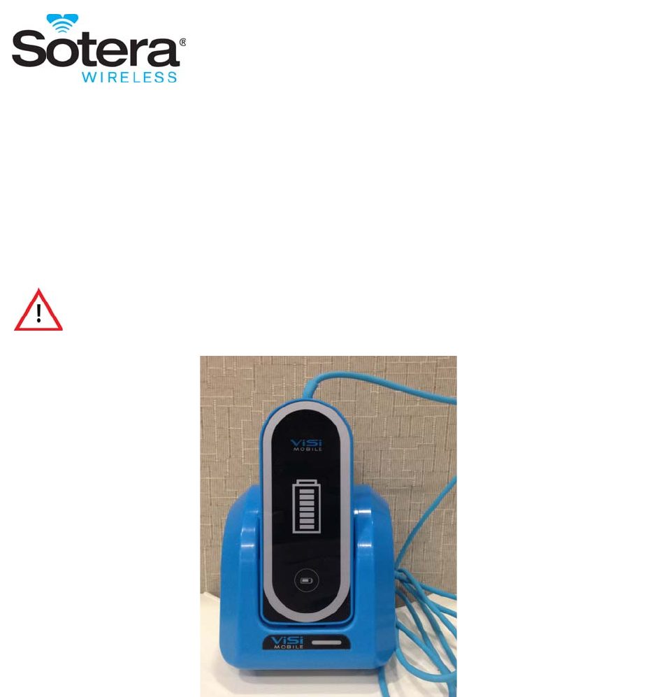
207
ViSi Power PackIntroduction
This user manual describes how to use the Sotera Wireless, Inc. ViSi Power Pack and provides information
for its proper operation. This product should only be used in conjunction with the ViSi Mobile Monitoring
System. Please review Appendix B -ViSi Power Pack in its entirety prior to use.
A formal knowledge of the features and functions of the ViSi Mobile Monitoring System are prerequisites
for its proper use.
Intended Use
The ViSi Power Pack is intended to be used by clinicians and medically qualified personnel only and is
used in conjunction with the ViSi Mobile Monitor. The ViSi Power Pack's only purpose is to extend
battery life for the ViSi Mobile Monitor so that battery power lasts a minimum of 24 hours.
Do not operate the ViSi Mobile Power Pack before reading these
instructions.

Warnings And Cautions
208
Note: The ViSi Power Pack is only designed to sustain the battery life of the internal ViSi Mobile
Monitor battery; it will not recharge the battery. When the ViSi Power Pack is disconnected,
the ViSi Mobile Monitor battery charge level is not expected to have increased.
Warnings And Cautions
Proper use of the ViSi Power Pack requires that it be in its cradle while
connected to the ViSi Mobile Monitor. This reduces the risk of electric shock
from exposure to the contact pins on the bottom rear of the ViSi Power
Pack.
Do not operate the ViSi Mobile Power Pack before reading these
instructions.
Never connect the ViSi Power Pack directly to an AC power outlet. To
recharge the battery, disconnect the Power Pack from the patient, and then
place it in the ViSi Mobile Charger. on page 15
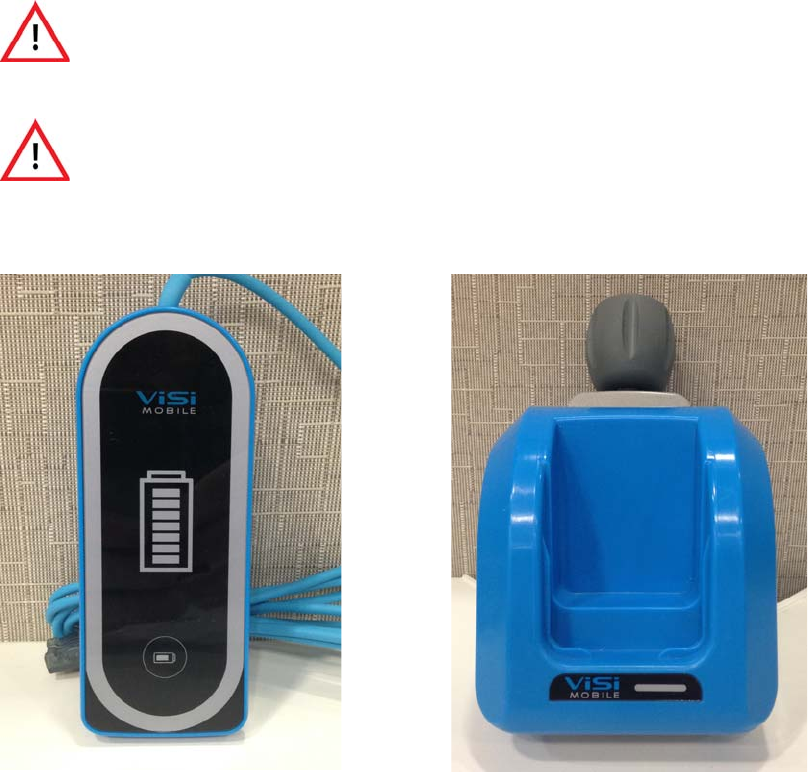
General Description
209
General Description
ViSi Power Pack
The ViSi Power Pack is a portable, battery operated power source that is used with the ViSi Mobile
Monitor. The ViSi Power Pack is not intended to be worn by the patient. It comes with a ViSi Power Pack
Cradle which only acts as a base for the Power Pack when in use and contains no electrical components.
The ViSi Power Pack should always be seated in the Power Pack Cradle when connected to the ViSi
Mobile Monitor. The Cradle has an integrated pole mount which can be attached securely at the patient
bedside. Alternately, the Cradle can be placed on a flat, fixed surface.
The ViSi Power Pack contains a rechargeable lithium-ion battery and should only be recharged using a
ViSi Battery Charger.
Do not touch the electrical contacts on the ViSi Power Pack or use the ViSi
Power Pack without it first being inserted into the ViSi Power Pack Cradle.
Doing so may result in electric shock from the battery. on page 15
If the ViSi Power Pack beeper/buzzer sounds or the Red LED is
permanently lit, the ViSi Power Pack should be disconnected from the
patient immediately. on page 15
ViSi Power Pack ViSi Power Pack Cradle
General Description
210
The Power Pack and has a cable that connects to the flat side of the ViSi Mobile Monitor when the Monitor
is in its Wrist Cradle. In addition to battery power, the cable also provides information on temperature,
voltage and current to the Monitor which will show a alert in case of failure.
The ViSi Power Pack can sustain the charge of the ViSi Mobile Monitor battery for at least 24 hours.
The ViSi Power Pack has a series of LED lights that indicate the amount of battery charge left (similar
operation to the ViSi NIBP Module) and will also communicate alerts as described on page 212. The ViSi
Power Pack will also beep and vibrate in the event of a failure.
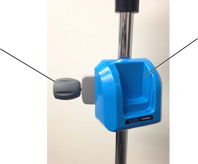
General Description
211
ViSi Power Pack Cradle
The ViSi Power Pack cradle comes with an optional pole mount that attaches to a bedside or IV pole for
greater stability or mobility for the patient.
OperationInspecting the Equipment
Before using the ViSi Power Pack, visually inspect each component of the ViSi Mobile Monitoring System
and Power Pack.
1. For each component, examine the exteriors for cleanliness and general physical conditions. Ensure
the housings are not cracked or broken, that everything is present, there are no spilled liquids and
no signs of abuse.
2. For each component, examine the exteriors for cleanliness and general physical conditions. Ensure
the housings are not cracked or broken, that everything is present, there are no spilled liquids and
no signs of abuse.For each component, examine the exteriors for cleanliness and general physical
conditions. Ensure the housings are not cracked or broken, that everything is present, there are no
spilled liquids and no signs of abuse.
3. Ensure there the ViSi Power Pack has adequate charge.
ViSi Power Pack
Pole Mount
(Optional) Seat
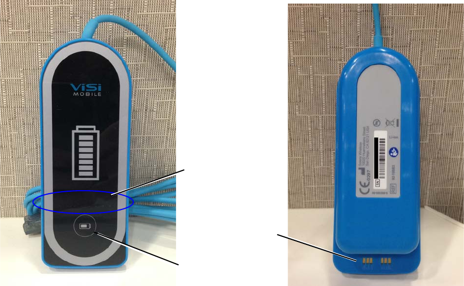
General Description
212
Checking the Battery Charge of the ViSi Power Pack
Press the Battery Status button on the front of the ViSi Power Pack.
There is a row of eight colored lights (Battery Status Indator LEDs) on the front surface of the ViSi Power
Pack.
Illuminated lights indicate the level of the battery charge:
• Green lights indicate the battery has a minimum of 11% charge. More green lights indicate a
greater charge level.
• When six illuminated green lights are visible, the ViSi Power Pack is fully charged.
• A yellow light indicates the battery charge is less than 10%.
• A flashing red light indicates there is less than 4% battery charge.
Note: A solid illuminated red light may indicate a failure of the ViSi Power. Disconnect ViSi Power
Pack from patient, or remove from ViSi Battery Charger and contact Sotera Wireless, Inc.
Customer Service.
ViSi Power Pack Front ViSi Power Pack Back
Charger
Contacts
Battery Status
Button
Battery Status
Indicator (LEDs)
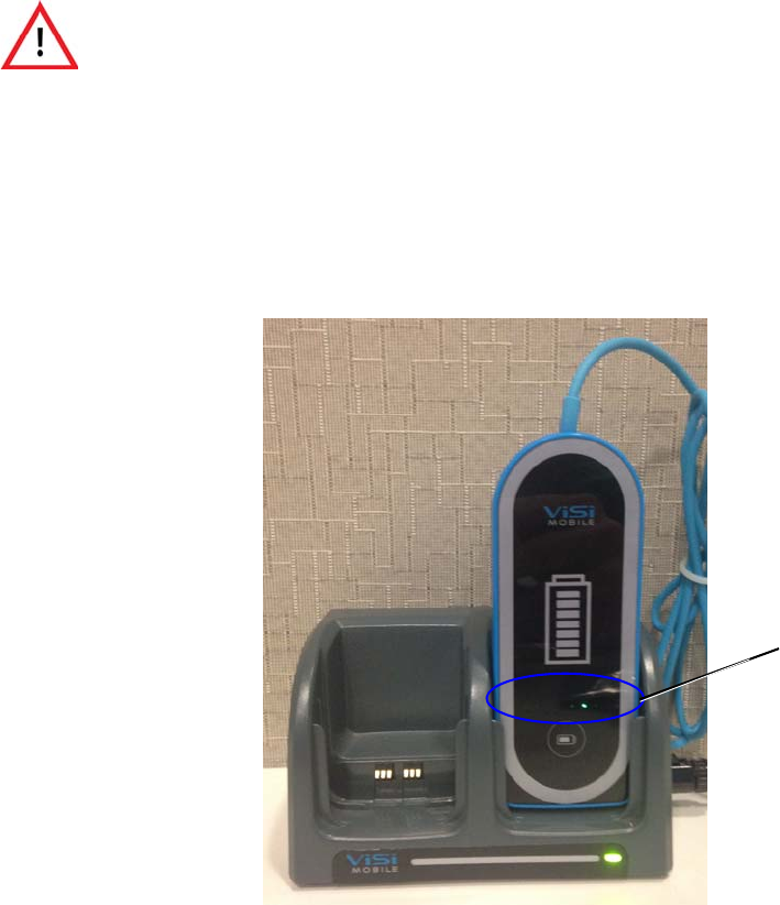
General Description
213
Charging the ViSi Power Pack
Note: For more information on setting up and using the ViSi Mobile Charger, see ViSi Mobile
Charger on page 40
The ViSi Mobile Charger provided by Sotera Wireless, Inc. is the required Charger for ViSi Power Pack.
The Charger is capable of charging up to eight of any combination of Power Packs, To charge the Power
Pack, place the flat end into one of the slots with the front facing outwards.
Insert the Power Pack that you want to charge into one of the Charger docks.
One of the charging indicator lights will blink while the Power Pack is charging.
Like with the Cuff Module, when one of the green charging indicators is flashing, the battery in the Power
Pack is charging. The position of the green charging indicator represents the level of charge. When the
charge indicator furthest away from the red charging indicator is flashing, the Power Pack is fully
charged.
When the yellow charging indicator is flashing, the battery in the Power Pack is low.
Never connect the ViSi Power Pack directly to an AC power outlet. To
recharge the battery, disconnect the Power Pack from the patient, and then
place it in the ViSi Mobile Charger.
Charging Indicator Lights
General Description
214
When the red charging indicator is flashing, the battery in the Power Pack has insufficient charge to power
the Monitor.
Note: The ViSi Mobile Charger is to be used for ViSi Mobile components only.
Note: ViSi Mobile Power Packs contain sealed batteries that are not replaceable by the user. If a
Power Pack has a battery issue, contact the Sotera Wireless, Inc. Customer Service
Department.
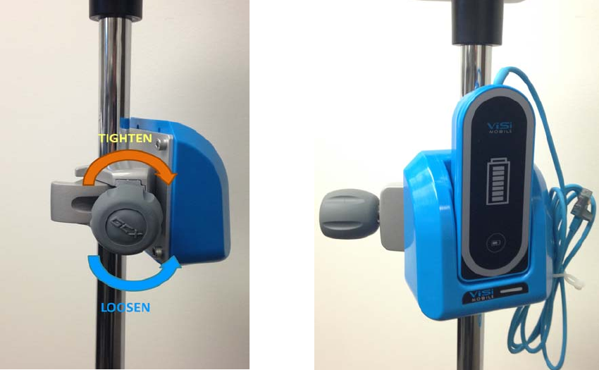
General Description
215
Setting up the ViSi Power Pack Cradle
The ViSi Power Pack Cradle can either be placed on a sturdy horizontal surface or can be attached to a pole
or bedframe with the optional pole mount.
To use the pole mount:
1. Loosen the pole clamp by turning the knob Counter-Clockwise
2. Tighten the pole clamp by turning the knob Clockwise
3. Place the Visi Power Pack in the Cradle with the front facing the outward with the flat side down.
Note: When the ViSi Power Pack is inserted in its Cradle, the Charger Contacts should not be
accessible.
Note: The ViSi Power Pack grooves will align with those of the Cradle when the Power Pack is
correctly seated.
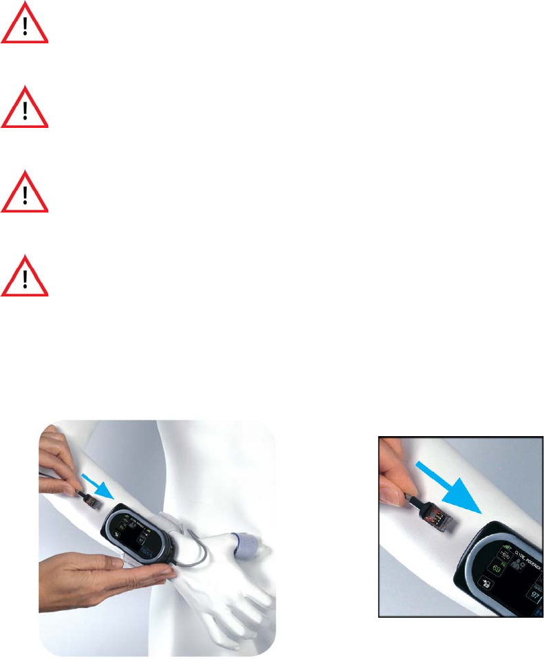
General Description
216
Using the ViSi Power Pack
Note: Only attach one ViSi Power Pack to the ViSi Mobile Monitor.
Plug the Power Pack connector into any of the open ports on the flat end of the Monitor with the connector
contacts facing upwards.
The ViSi Power Pack and the Monitor will make a beeping noise to indicate that the Power Pack is
connected. Once connected, the Power Pack will automatically begin to provide auxilliary power to the
Monitor.
To stop using the Power Pack, simply disconnect from the Monitor.
Do not touch the electrical contacts on the ViSi Power Pack or use the ViSi
Power Pack without it first being inserted into the ViSi Power Pack Cradle.
Doing so may result in electric shock from the battery.
Route all ViSi Mobile Monitoring System cabling to avoid the possibility of
patient entanglement or strangulation.
The ViSi Power Pack Alarms/Alerts DO NOT audibly annunciate on the ViSi
Mobile Monitor or the Remove Viewing Device.
If the ViSi Power Pack beeper/buzzer sounds or the Red LED is
permanently lit, the ViSi Power Pack should be disconnected from the
patient immediately.
Insert with connectors
contacts facing upwards

General Description
217
It is recommended to place the ViSi Power Pack in the ViSi Mobile Charger (see section ViSi Mobile
Charger on page 40) between uses.Replacing the ViSi Power Pack
To replace a depleted ViSi Power Pack while still monitoring a patient:
1. Disconnect the ViSi Power Pack from the Monitor
2. Remove the Power Pack from the Power Pack Cradle
3. Insert new Power Pack into the Cradle
4. Connect the new Power Pack to the Monitor
When not in use, disconnect the ViSi Power Pack from the Monitor.
Do not touch the electrical contacts on the ViSi Power Pack or use the ViSi
Power Pack without it first being inserted into the ViSi Power Pack Cradle.
Doing so may result in electric shock from the battery.

Equipment Alerts
218
Equipment Alerts
The ViSi Power Pack has technical alerts that are intended to notify the clinician of situations that may be
hazardous or impede the ability of the Power Pack to provide power to the Monitor.
Note: For a listing of these Alerts, please see Alarm Summary on page 199
Note: In the event of a Power Pack malfunction while it is connected to a ViSi Mobile Monitor, the
Monitor will indicate “Battery Pack Fault”.
User/Preventative Maintenance
See User/Preventative Maintenance on page 105 for instructions on the maintenance of the ViSi Power
Pack.
Troubleshooting
See section Troubleshooting on page 147 for instructions on troubleshooting the ViSi Power Pack.
The ViSi Power Pack Alarms/Alerts DO NOT audibly annunciate on the ViSi
Mobile Monitor or the Remove Viewing Device.
If the ViSi Mobile Monitor displays a “Battery Pack Fault” , “Electric Shock”,
or “Monitor Too Hot” message, disconnect the Power Pack immediately.
Troubleshooting
219
- Notes -
Troubleshooting
220
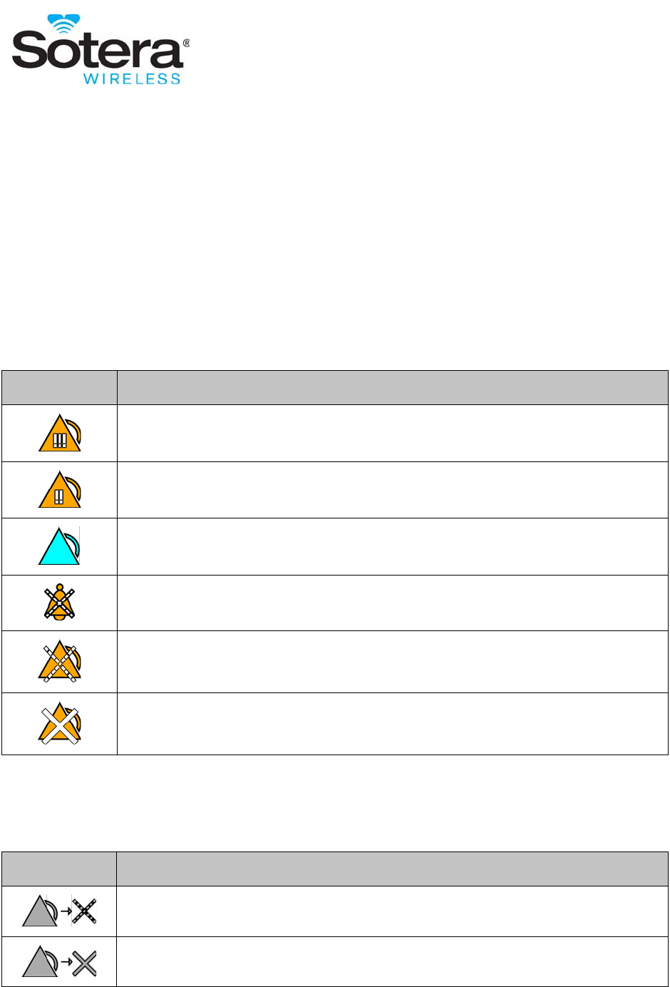
221
Appendix C - Symbols
Alarms / Alerts
Alarm / Alert States
Alarm Management
Symbol Description
Unacknowledged life threatening severity alarm in progress.
Unacknowledged high severity alarm in progress
Unacknowledged alert in progress (any severity).
All alarms in progress have been acknowledged by the clinician.
Alarm annunciation (visual and audio) has been paused for 2 minutes.
Alarm annunciation (visual and audio) has been turned off.
Symbol Description
Pause alarm annunciation (visual and audible) for 2 minutes.
Turn off alarm annunciation (visual and audible).

Alarms / Alerts
222
Resume alarm annunciation from a paused state.
Turn alarm annunciation back on.
Acknowledge an alarm/alert that is in progress.
Symbol Description

Battery States
223
Battery States
ViSi Mobile Monitor
ViSi Power Pack
When the ViSi Power Pack is connected to a Monitor, the Monitor screen will show the battery level of the
Power Pack.
Battery
Icon
Status
Monitoring a Patient / Not in Charger In Charger
The battery status in the ViSi Monitor is good
and has at least three hours of monitoring
available.
Note: The fill level will diminish as the
battery level goes down.
The battery is at least 90% charged.
Note: The LED on the front of the
Monitor will be flashing green.
The battery in the ViSi Monitor is low.
There is less than 3 hours of monitoring
available.
The battery is charged between 40% and 90%.
Note: The LED on the front of the
Monitor will be flashing yellow.
The battery in the ViSi Monitor is critically
low.
There is less than 1 hour of monitoring
available.
The battery charge is less than 40%.
Note: The LED on the front of the
Monitor will be flashing yellow.
The battery in the ViSi Monitor is too low to
continue monitoring.
There is less than 10 minutes of battery charge
left.
The Monitor will not wake up when it is in the
Charger.
Battery
Icon Status
The battery in the Power Pack is charged. Remaining battery level is >10 % .
The battery in the Power Pack is low. Remaining battery level is between 4% - 10%.

Battery States
224
The battery in the Power Pack is critically low. Remaining battery level is <4% and too low to
charge a Monitor.
Battery
Icon Status
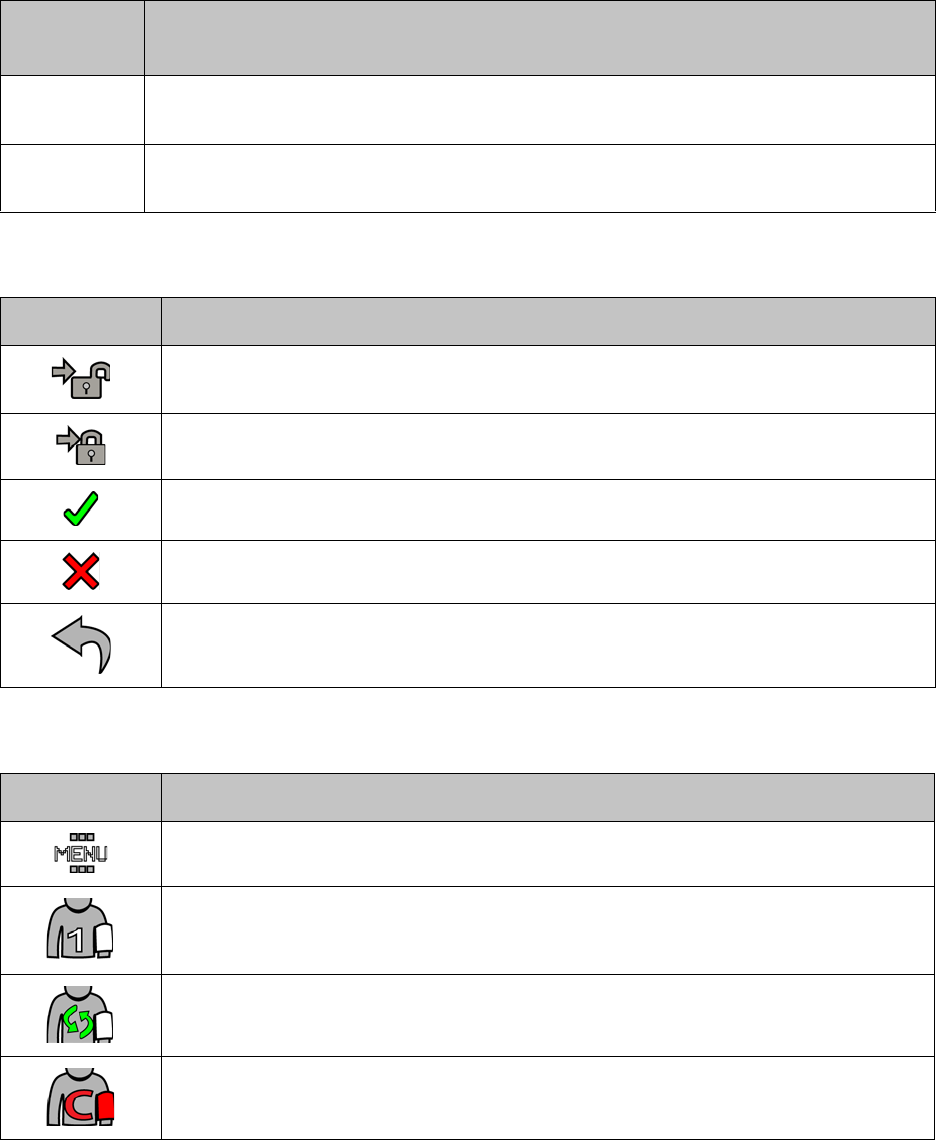
General Icons
225
General Icons
Out of Range Vital Signs
Navigation
Vital Signs Menu
Symbol Description
+++ Vital sign measurement is above the upper display range.
--- Vital sign measurement is below the lower display range.
Unlock the ViSi Mobile Monitor to gain access to the clinical features.
Lock the ViSi Mobile Monitor to prevent unwanted access to the clinical features.
Confirm activity.
Cancel activity.
Return to the previous screen.
Symbol Description
Access to the clinical menu.
Start a manual cuff inflation. Cuff inflations are set up to be taken on a PRN basis.
Start automatic cuff inflations. Cuff inflations are set up to be taken automatically at a
selected time interval.
Calibrate NIBP for continuous measurements.
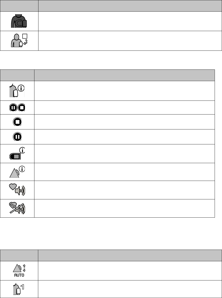
General Icons
226
Clinical Menu
Other
Calibrate cNIBP for continuous measurements. Patient’s PAT is not yet stable.
Stop a cuff inflation currently in progress.
Symbol Description
BP management. Setup the cuff inflation intervals.
Initiate the pause/stop monitoring sequence.
Initiate the stop monitoring sequence.
Initiate the pause monitoring sequence.
Access information regarding the ViSi Mobile Monitor: Monitor ID, MAC address, Serial
#, software version installed and battery status.
Alarm management. Review the patient’s current alarm limits, adjust the alarm limits using
“Auto Set” or turn off the alarm annunciation.
QRS beep is turned on.
QRS beep is turned off.
Symbol Description
Change a patient’s alarm limits using “Auto Set”.
Setup cuff inflation to be on a PRN basis.
Symbol Description

General Icons
227
Setup cuff inflation such that the cuff will inflate at defined intervals.
Setup cuff inflation such that NIBP measurements will be taken on a continuous basis.
Monitor is ready to perform device swap.
Symbol Description
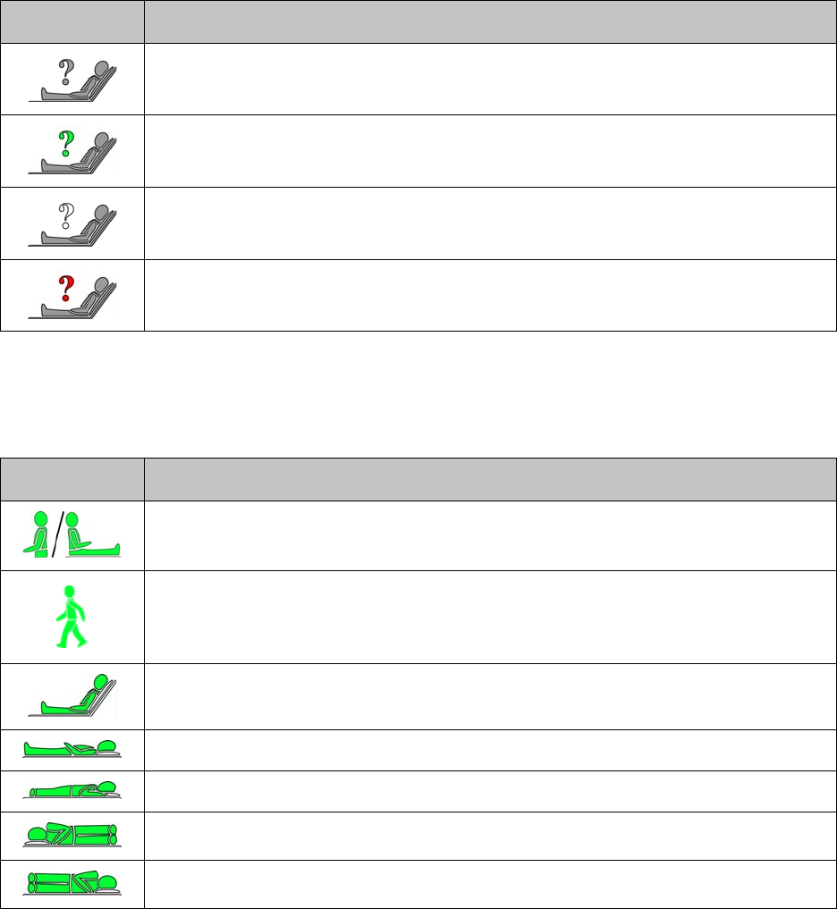
Patient’s Postures
228
Patient’s Postures
Unknown Posture
Postures
a. When the ViSi Mobile Monitor has identified a Patient as walking for two consecutive updates, the cNIBP
monitoring will be paused for a mininum of 30 seconds.
Symbol Description
Patient is currently out of the network.a
a. The ViSi Mobile Monitor always displays the question mark in gray irrespective of the alarm status.
Patient’s posture has not been selected and confirmed on the ViSi Mobile® Monitor. There
are no alarm conditions in progress.
Patient’s posture has not been selected and confirmed on the ViSi Mobile® Monitor. A life-
threatening alarm condition is in progress.b
b. In the event of a life-threatening alarm, the question mark above the patient symbol will toggle white/red.
Patient’s posture has not been selected and confirmed on the ViSi Mobile® Monitor. When
the question mark is static red, a high alarm condition is in progress.
Symbol Description
Patient’s torso is in an upright position or the Patient is walkinga on the Wrist Monitor.
Patient is walking. This symbol will be displayed on the ViSi Mobile Remote Viewer only.
Patient’s torso is at a semi-Fowler’s position.
Patient is lying in a supine position.
Patient is lying in a prone position.
Patient is lying on their right side.
Patient is lying on their left side.
Labelling
229
Labelling
Symbol Description
Warning, refer to accompanying documents
Caution, refer to accompanying documents
WiFi Alliance certification
Conforms with EEC directives
Catalog number
Serial Number
Manufactured By
Defibrillator proof type CF equipment
This product is designated for separate collection at an appropriate collection point. Do not
dispose of as household waste.
Lithium Ion battery
IPX0 No special protection.
IPX7 Protected against water immersion. Immersion for 30 minutes at a depth of 1 meter.
Latex free
Do not reuse
Fragile
Labelling
230
Contents
MRI Unsafe
Non-ionizing radiation
Caution, refers to accompanying electronic document
Symbol Description
CONT
Labelling
231
- Notes -
Labelling
232

233
Appendix D - Warranty
Warranty
Sotera Wireless, Inc. warrants to End User, for a period of one (1) year from the date of delivery, unless
otherwise noted in specific documentation, that the products sold by Sotera Wireless, Inc. will operate in
accordance with Sotera Wireless, Inc.’s published documentation in effect on the date of delivery or Sotera
Wireless, Inc. will, at its sole discretion and expense, repair or replace the products. Replacements will be
warranted for the remainder of the warranty period in effect on the original product purchased, unless
otherwise mandated by applicable law. Products include Sotera Wireless, Inc. equipment only but does not
include disposables / consumables. Sotera Wireless, Inc. warrants that its disposables / consumables
products will be free from defects in workmanship and materials for a period of one (1) year from the date
of purchase or the expiration date whichever occurs first.
Third Party Branded Products
Sotera Wireless, Inc. will not be deemed to provide, nor be responsible for, warranty, related remedy or
support with respect to hardware, software or services purchased from a third party unless such party is a
Sotera Wireless, Inc. authorized partner services Sotera Products and Services, unless otherwise agreed in
writing between the parties.
Typically, in case of a defective 3rd party item under warranty, Sotera Wireless, Inc. will make
arrangements with the 3rd party manufacturer to issue a replacement. The replacement will be sent
directly to the End User site from the 3rd party manufacturer. No Return Material Authorization (RMA)
will be issued by Sotera Wireless, Inc., instead a Sotera Case Number will be issued for the reported issue.
The End User is responsible for complying with the manufacturer’s replacement procedures.
Warranty Exclusions
Sotera Wireless, Inc. will not be liable under this warranty if its testing and/or examination discloses that
the alleged defect in the Sotera Wireless, Inc. equipment does not exist or was caused by end user’s or any
unauthorized third person’s misuse, neglect, improper installation or testing, attempts to repair, or any
other cause beyond the scope of the intended use, or by accident, fire, lightning or other hazard or event of
force majeure. The warranty for any hardware will become void if a hardware component is installed as an
add-on and/or replacement part on the original hardware and such component part has not been approved
for such inclusion by Sotera Wireless, Inc. The warranty for software will be voided if the software is
modified, except as authorized in writing by Sotera Wireless, Inc.
Sotera Wireless, Inc. Responsibility
234
In no event shall Sotera Wireless, Inc. be liable to end user or any third parties for any consequential,
incidental, indirect, exemplary, punitive, contingent, statutory or any other special damages. Sotera
Wireless, Inc.’s liability for damages on account of a claimed defect in any product delivered by Sotera
Wireless, Inc. shall in no event exceed the purchase price of the product on which the claim is based.
Specifically, and without limiting the generality of the foregoing, Sotera Wireless, Inc. shall not be
responsible or liable to end user or any third party for any lost profits, or any consequential, incidental,
punitive, contingent, statutory or any other special damages for any breach of warranty or other breach of
Sotera Wireless, Inc.’s obligations under this agreement. Sotera Wireless, Inc. shall not be liable for
damages relating to any instrument, equipment, or apparatus with which the product sold under this
agreement is used. In addition, Sotera Wireless, Inc. disclaims all liability of any kind of Sotera Wireless,
Inc.’s suppliers.
The foregoing warranties and remedies are exclusive and are in lieu of all other warranties, express or
implied, either in fact or by operation of law, statutory or otherwise including warranties of merchantability
and fitness for a particular purpose or non infringement.
Sotera Wireless, Inc. does not assume or authorize any other person to assume for it any other or greater
liability in connection with the sale, installation, servicing, maintenance or use of Sotera Wireless, Inc.
hardware, and Sotera Wireless, Inc. makes no warranty whatsoever with respect to any third-party branded
products supplied by it hereunder.
Sotera Wireless, Inc. Responsibility
Sotera Wireless, Inc. is responsible for the effects on safety, reliability and performance of the equipment
only if:
1. Assembly operations, extensions, readjustments, modifications or repairs are carried out by
persons authorized by Sotera Wireless, Inc. and
2. The equipment is used in accordance with the instructions for use.
Contact Sotera Wireless
Toll-Free: +1-866-232-6126
International: +1-858-427-4620
Fax: +1-858-999-2487
E-mail: support@soterawireless.com

235
Index
A
Alarm Summary 199
Alarm Summary on page 195 219
Alarms 81
Alarms/Alerts
Annunciation Rules 83
Managing Annunciations 84
Monitor Battery Too Hot 102, 103
Pause & Resume 91
Responding To 85, 89
Set Alarm Limits 96
Testing Annunciation 101
Turn Off (All Alarms) 93
Alerts
Charging 205
Chest Sensor Cable 202
Cuff Module 203
ECG 202
Miscellaneous 204
Monitor 201
SpO2 203
Thumb Sensor 203
All Sensors Disconnected 145
C
Cable Securement 35
Cautions 23
Charger 40
Chest Sensor Cable 38
Cleaning and Disinfection 106, 143
Clinical Features 45
Key Features 47
Overview 47
Contraindications 12
Copyright 2
Cuff 32
Cuff Module 37
236
Calibration Check 37
Charging 44
Power Indicator 37, 60
Customer Support 147, 234
D
Display/Screens 50
All Sensors Disconnected 145
Battery Charge 50
Confirm Device Swap 138
Confirm Patient’s Demographics 134
Confirm Sensor Placement 133
Device Status 136
Device Swap 136
Disconnect Sensors 138
Hibernation 51
Menu 53
Monitor Status 54
Operation Instructions 138
Patient View 55, 114
Pause/Stop Monitoring 140, 142
Pause-Disconnect Sensors 141
Pin Code 115
Quiet Monitoring 54
Select Patient Posture 132
Stop-Disconnect Sensors 143
Vital Signs 52, 116
Waiting Patient Transfer 138
Waveforms 117
Disposable Kit 31
Cable Securements 35
Cuff 32
ECG Electrodes 33
Product Disposal 111
Thumb Wrap 33, 34, 40
Wirst Cradle (Monitor) 33
E
ECG Electrodes 33
Equipment Inspection 109
Charger 109
Chest Sensor 109
Cuff Module 109
Exchange Monitor with Low Battery 136
I
In the event of a Power Pack malfunction while it is connected to a ViSi Mobile Monitor, the Mon-
itor will indicate “Battery Pack Fault”. 219
Intended Use 12
237
L
Lock Monitor 114
M
Monitor
Charging 42
Power Indicator 35, 60
Monitoring
ECG/HR 47
Non-Invasive Blood Pressure (NIBP) 49
Pulse Oximetry 48
Respiration 47
Skin Temperature 48
Monitoring Setup
Apply Chest Sensor Cable 72
Apply Thumb Sensor 66
Apply Wrist Cradle 64
Lock in the Monitor 65
Motion Artifacts 121
N
NIBP 122, 203
Automatic Inflations 127
Calibrate for continuous measurements (cNIBP) 129
Continuous Measurements 129
Recalibrate continuous measurments 131
Selecting Blood Pressure Mode 123
Single/1-Time Measurements 124
Stop Cuff Inflation 126
P
Patient Monitoring 113
Applying Sensors 57, 70
Preparing New Patient 57, 69
Selecing Chest Sensor (3 Lead-Wire / 5 Lead-Wire) 59
Selecting Appropriate Vital Signs 59
Patient Posture
Confirm Sensor Placement 133
Select/Confirm 132
View 132
Patient’s Demographics 134
Confirm 134
Reject 134
View 135
Pause Monitoring 139
Physiological Alarms
High 200
Life Threatening 199
Pin Code Entry 115
238
Power Pack 209
Alerts 219
Charging 212
Cradle 210, 215
Maintenance 219
Operation 211
Power Indicator 212
Replacing 217
Troubleshooting 219
Using with Monitor 216
Preventative Maintenance 105
Product Disposal 111
R
Remove Sensors (From Patient) 77
S
Specifications 161
Physical Components 174
2-Bay Charger 179
8-Bay Charger 179
Appliance 181
Chest Sensor Cable 176
Cuff Module 177
Customer Network 183
Mode Plugs 175
Monitor 174
Remote Viewer 182
Thumb Sensor 178
Wireless Communication/Radio 174
Vital Signs
Continuous Non-Invasive Blood Pressure 170
Heart Rate 162
Non-Invasive Blood Pressure 168
Pulse Oximetry 166
Respiration 165
Skin Termperature 173
Stop Monitoring 142, 145
Symbols 221
Alarms/Alerts 221
Battery Status 206
Generic Icons 225
Labelling 225
Wireless Radio Signal Strength 206
T
Thumb Sensor 36
Thumb Wrap 34
Troubleshooting 147
239
Alarms and Alerts 157
Battery Charger 155
Chest Sensor Cable 149
Connectivity Lost 157
Cuff Module 153
Monitor 148
Setting Alarm Limits (Remote Viewer) 159
Thumb Sensor 152
U
Unlock Monitor 114
V
ViSi Mobile Monitor 35
ViSi Power Pack 207
Vital Signs 116
W
Warnings 14
Warranty 233
Exclusions 233
Third Party Products 233
Waveforms 117
Dynamic Range 119
ECG (5 Lead-Wire only) 118
Input Overload 119
Respiration 120
SpO2 120
240
- Notes -