Sotera Wireless VISI-MOBILE ViSi Mobile Monitoring System User Manual RVD IFU
Sotera Wireless, Inc. ViSi Mobile Monitoring System RVD IFU
UserManual.wiki
>
Sotera Wireless
>
VISI-MOBILE User Manual
>
User Manual
Contents
1.
User manual
2.
User Manual
User Manual
Navigation menu
Upload a User Manual
Namespaces
Wiki Guide
HTML
PDF
Info
Views
User Manual
Discussion / Help
Navigation
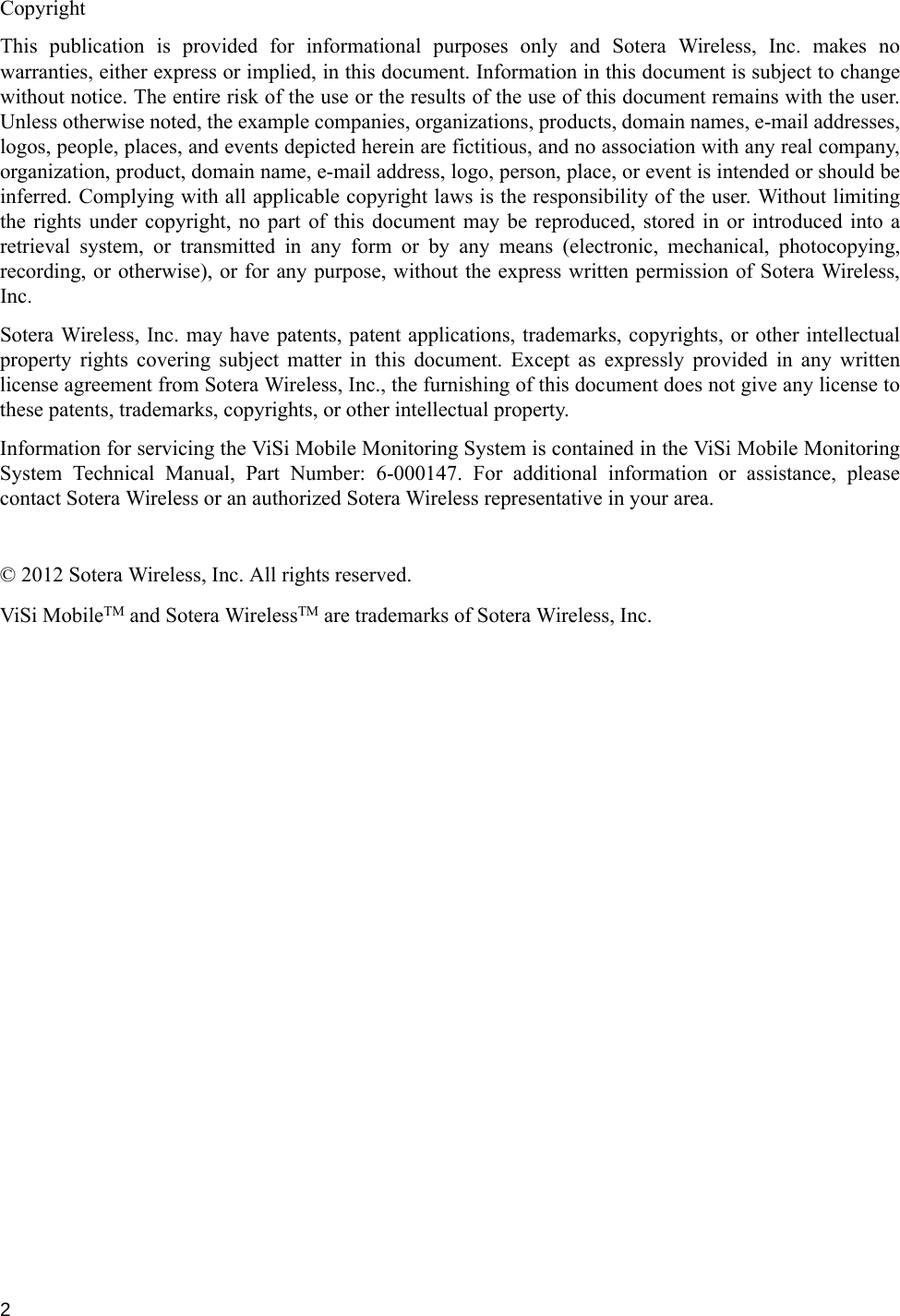
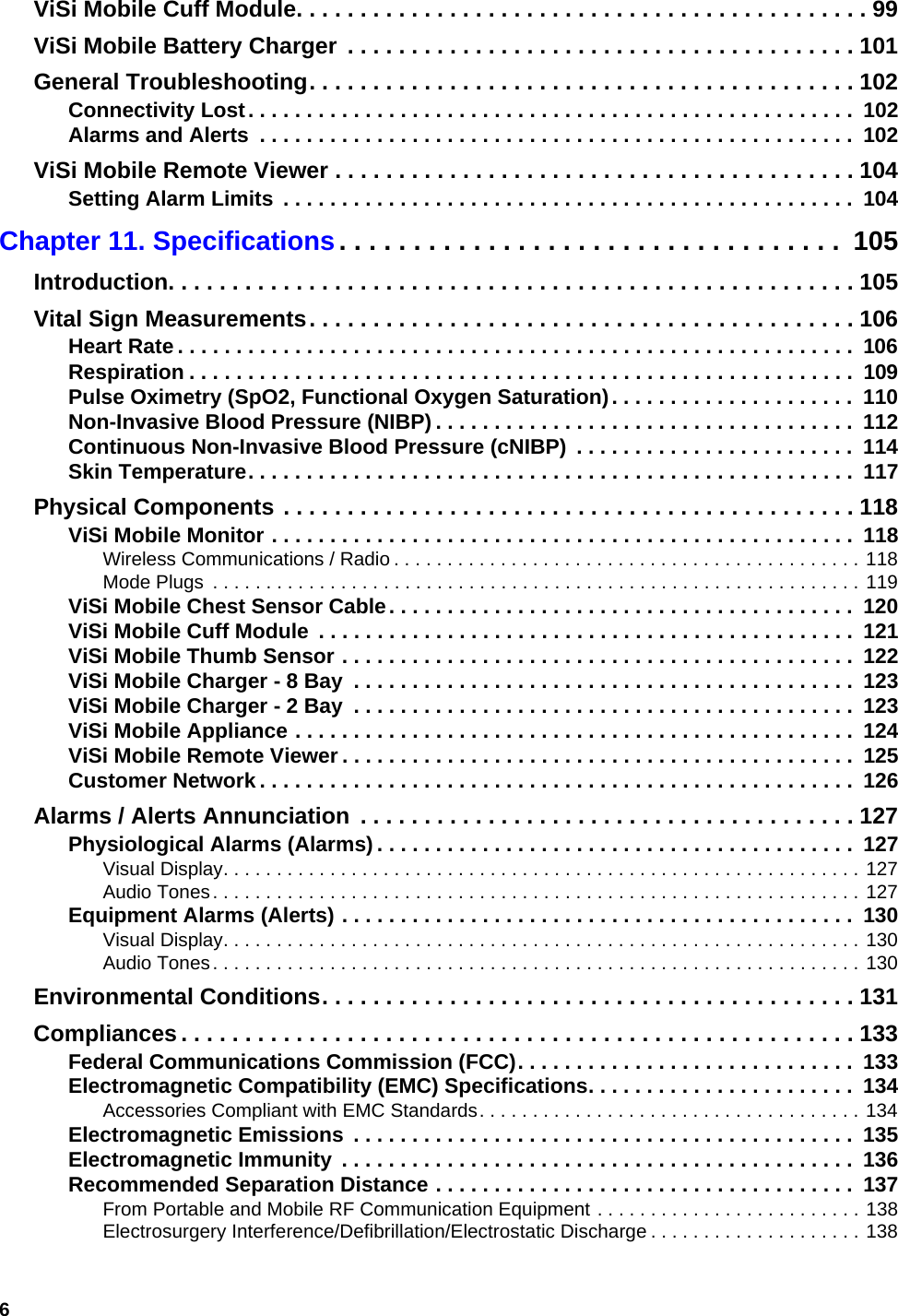


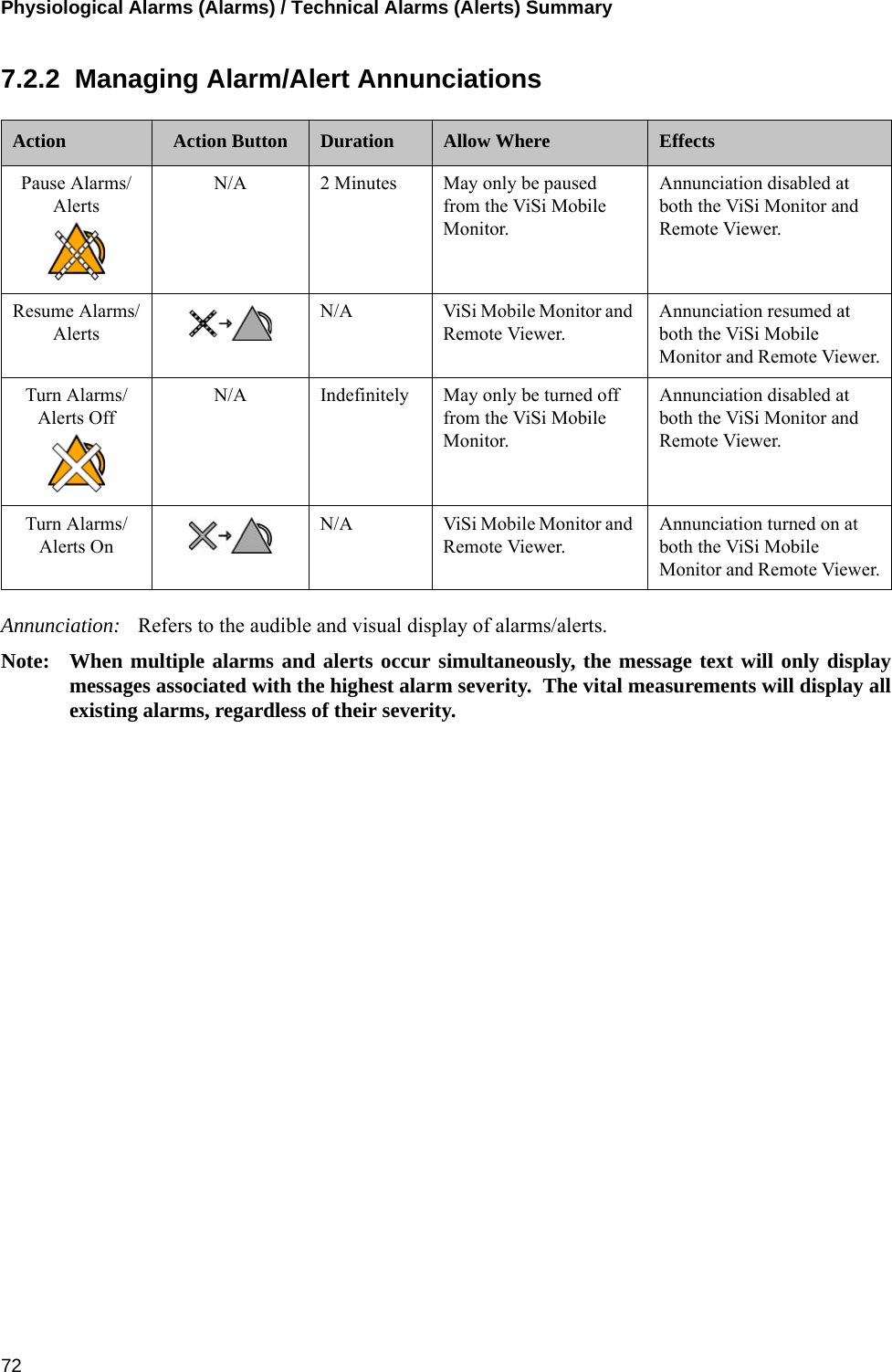
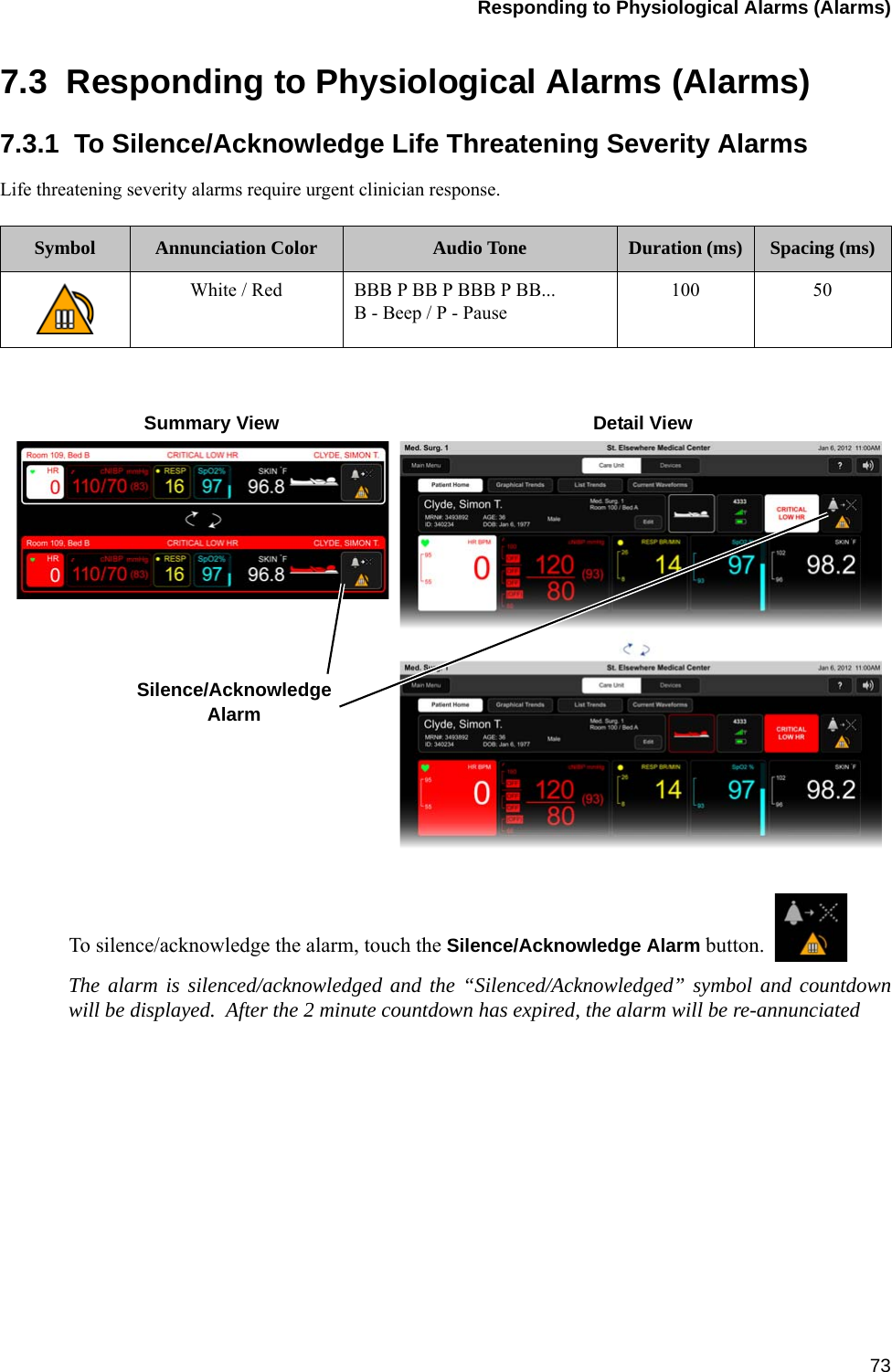
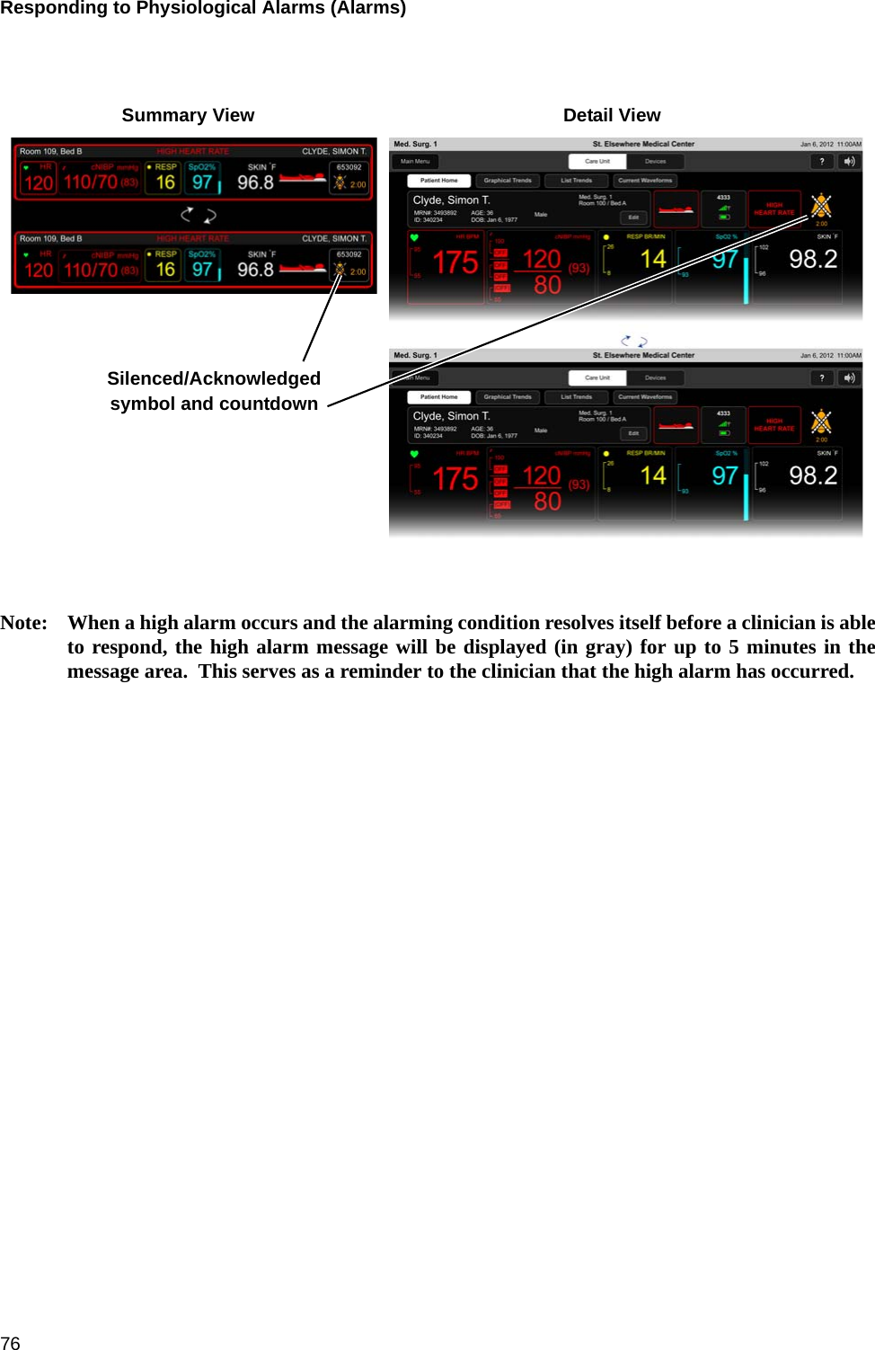
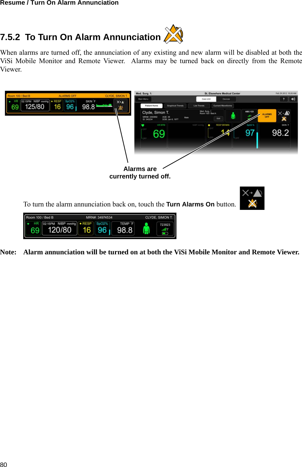
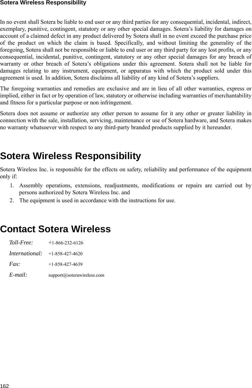
![Alarms / Alerts Annunciation12711.4 Alarms / Alerts AnnunciationNote: An “Annunciation Delay” is the time that an alarm system deliberately delays the alarmannunciation (audibly and visually) to ensure clinical relevance of the detected alarmingcondition. Within the tables below, see column “Annunciation Delay” for the pre-definedperiods of time.Note: When the ViSi Mobile Monitor is connected to a network (as indicated by the networksymbol in the top left hand corner of the display), the audio annunciation of non-life-threatening alarms/alerts will be deferred to the ViSi Mobile Remote Viewer for a pre-configured period of time. Within the tables below, see column “Deferral Delays” for thepre-defined periods of time.11.4.1 Physiological Alarms (Alarms)Visual DisplayThe following table outlines the visual display when alarms are in progress:Audio TonesThe following table outlines the audio tones when alarms are in progress:Alarm Limits and Delays (factory default settings).Severity Indicator Attributes Toggle / Flash Speed Duty CycleHigh Priority Red 1.5 Hz 50% ONLife-Threatening Priority Red / White 1.5 Hz 50% ONSeverity Melodyaa. Melodies are defined as musical notes.Volume[dB] Frequency(fo) [Hz] Duration(td) [ms] Spacing(ts) [ms] 5th-6th[s] Inter-Burst(tb) [s]Life Threatening b5.b5.b5..b5.b5 78 987.767 100 50 0.35 2.5High b5.b5.b5..b5.b5 78 987.767 200 100 0.35 5Vital Sign Lower Limit Upper Limit Annunciation Delaya(seconds) Deferral Delay(seconds)Care Unit Patient Patient Care Unit Patient Care UnitbCritical Low HR (BPM) 18 18 N/A N/A 5 5 30Heart Rate (BPM) 30 30 150 200 5 5 60Pulse Rate (BPM) 30 30 150 200 30 30 60BP Systolic (mmHg) 70 OFF 190 240 60 30 90BP Diastolic (mmHg) 40 OFF OFF 150 60 30 90BP MAP (mmHg) 60 65 OFF 170 60 30 90](https://usermanual.wiki/Sotera-Wireless/VISI-MOBILE.User-Manual/User-Guide-2225721-Page-127.png)
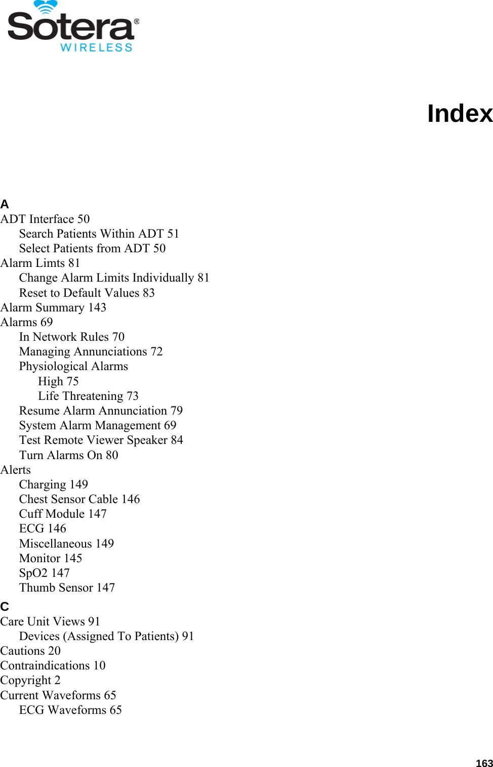
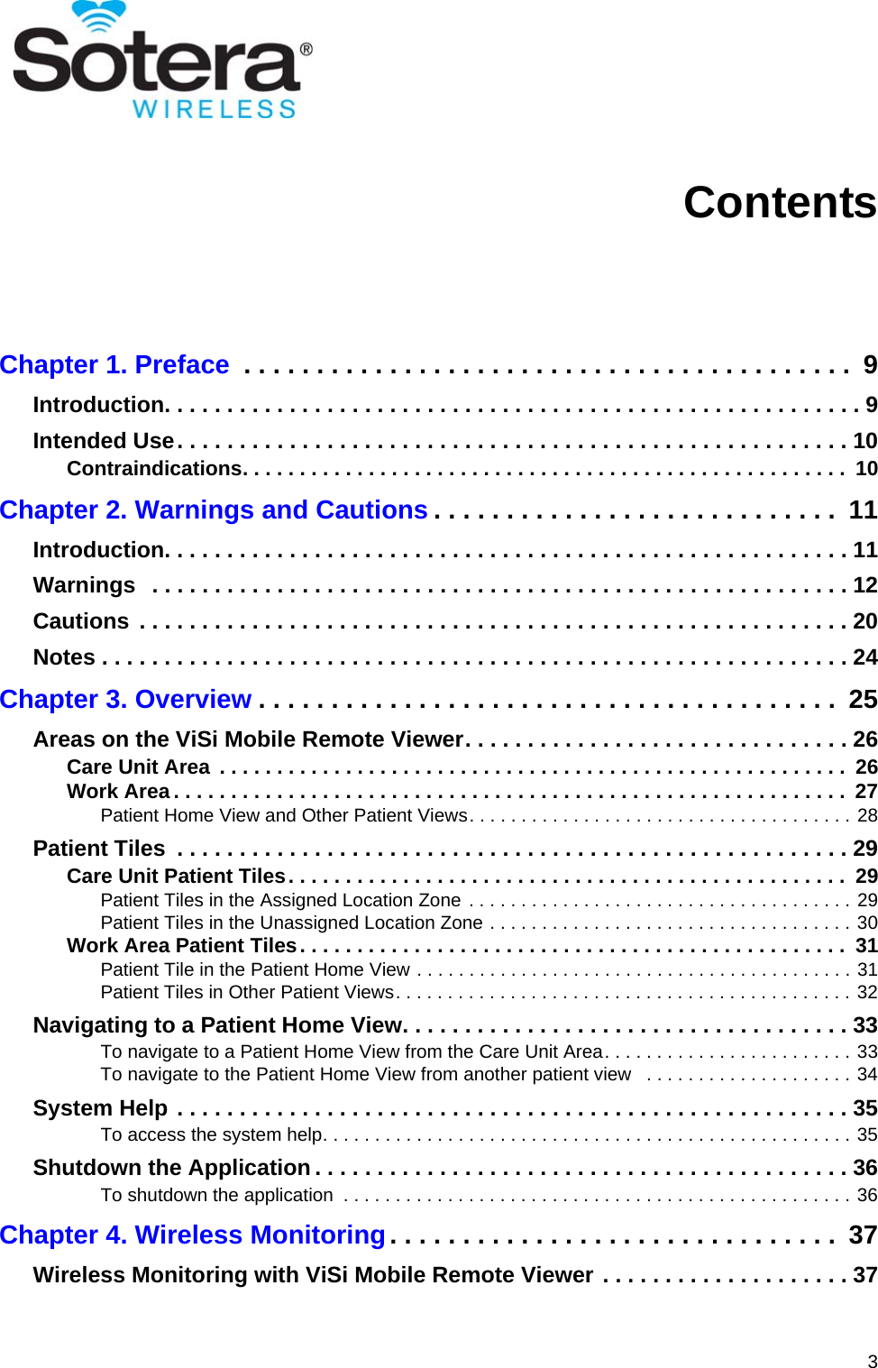
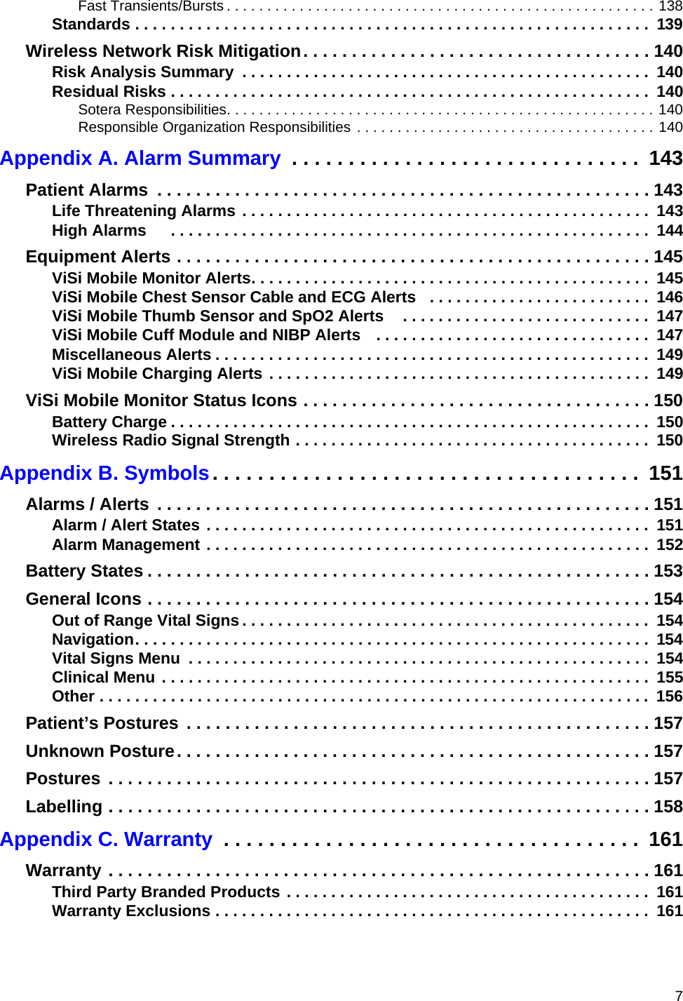
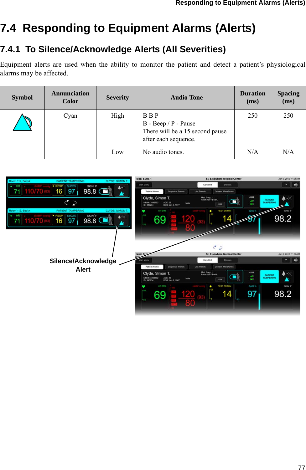
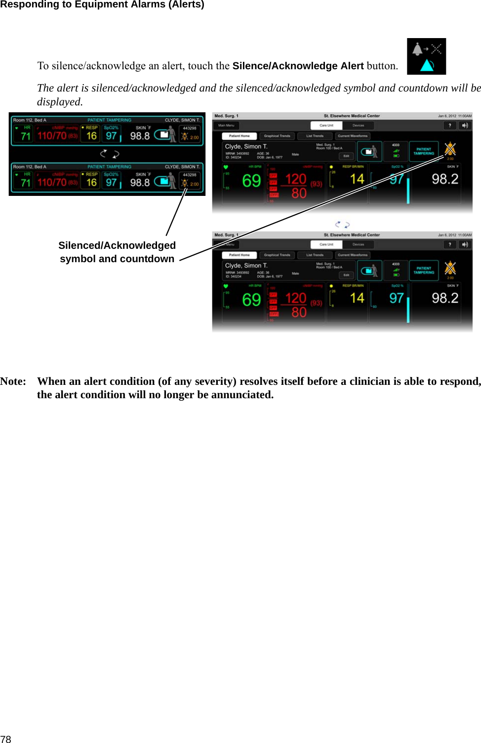
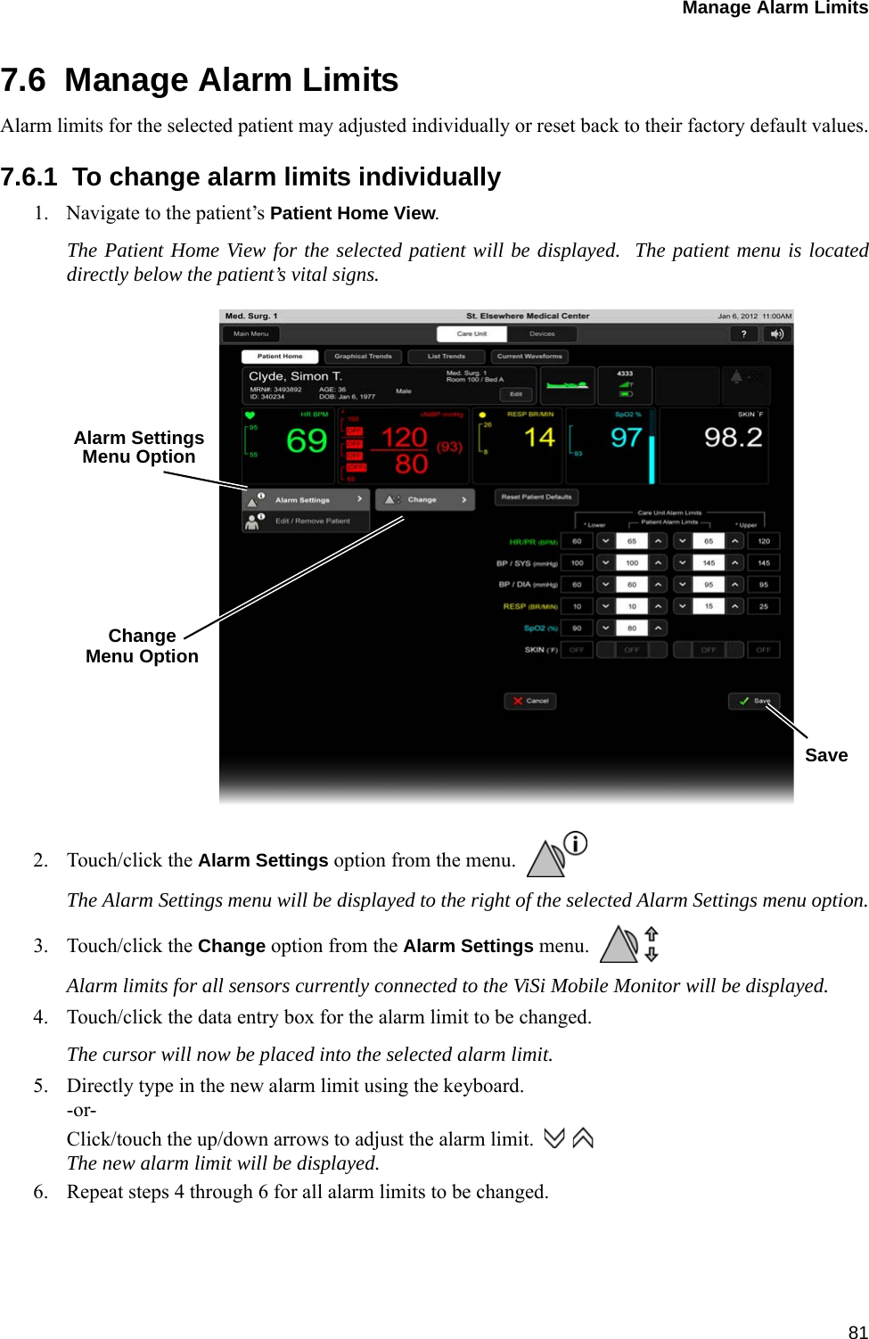
![Alarms / Alerts Annunciation 13011.4.2 Equipment Alarms (Alerts)Visual DisplayThe following table outlines the visual display when alerts are in progress:Audio TonesThe following table outlines the audio tones when alerts are in progress:Note: There are no audio tones associated with low severity alerts.Alarm Limits and Delays (factory default settings)Severity Indicator Attributes Toggle / Flash Speed Duty CycleAll Severities Cyan (Blue) Constant (ON) 100% ONSeverity Melodyaa. Melodies are defined as musical notes.Volume[dB] Frequency(fo) [Hz] Duration(td) [ms] Spacing(ts) [ms] Inter-Burst(tb) [s]High e5.c5 68/63 659.255, 523.251 250 250 15Chest Sensor Alerts Limit(if applicable) AudibleAlertDelays (in seconds)Annunciation DeferralECG Lead Failure N/A No No delay N/AAll ECG Lead Failure N/A No No delay N/AChest Sensor Disconnected N/A No No delay N/AGeneral Fault Detected N/A No No delay N/AMultiple Connections N/A No No delay N/ATemperature Sensor Fault N/A No No delay N/AAccelerometer Fault - Chest Module N/A No No delay N/AAccelerometer Fault - Upper Arm N/A No No delay N/AThumb Sensor Alerts Limit(if applicable) Audible AlertDelays (in seconds)Annunciation DeferralThumb Sensor Off N/A No < 30 N/AThumb Sensor Disconnected N/A No No delay N/A](https://usermanual.wiki/Sotera-Wireless/VISI-MOBILE.User-Manual/User-Guide-2225721-Page-130.png)