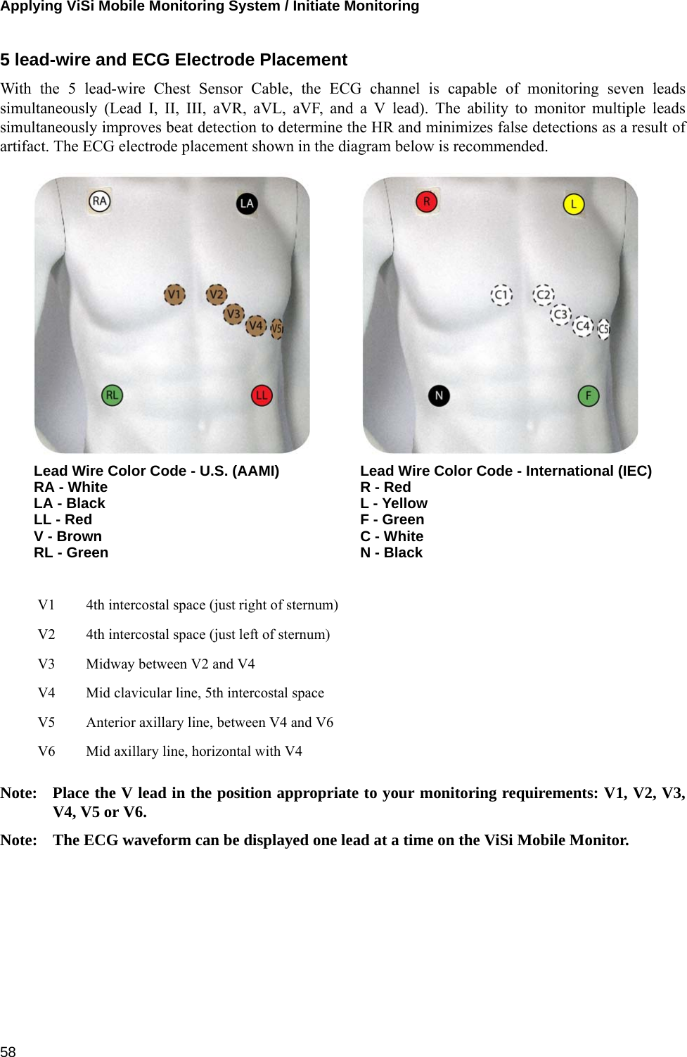
Sotera Wireless VISI-MOBILE Vital Signs Monitoring system User Manual PWD IFU
Sotera Wireless, Inc. Vital Signs Monitoring system PWD IFU
UserManual.wiki
>
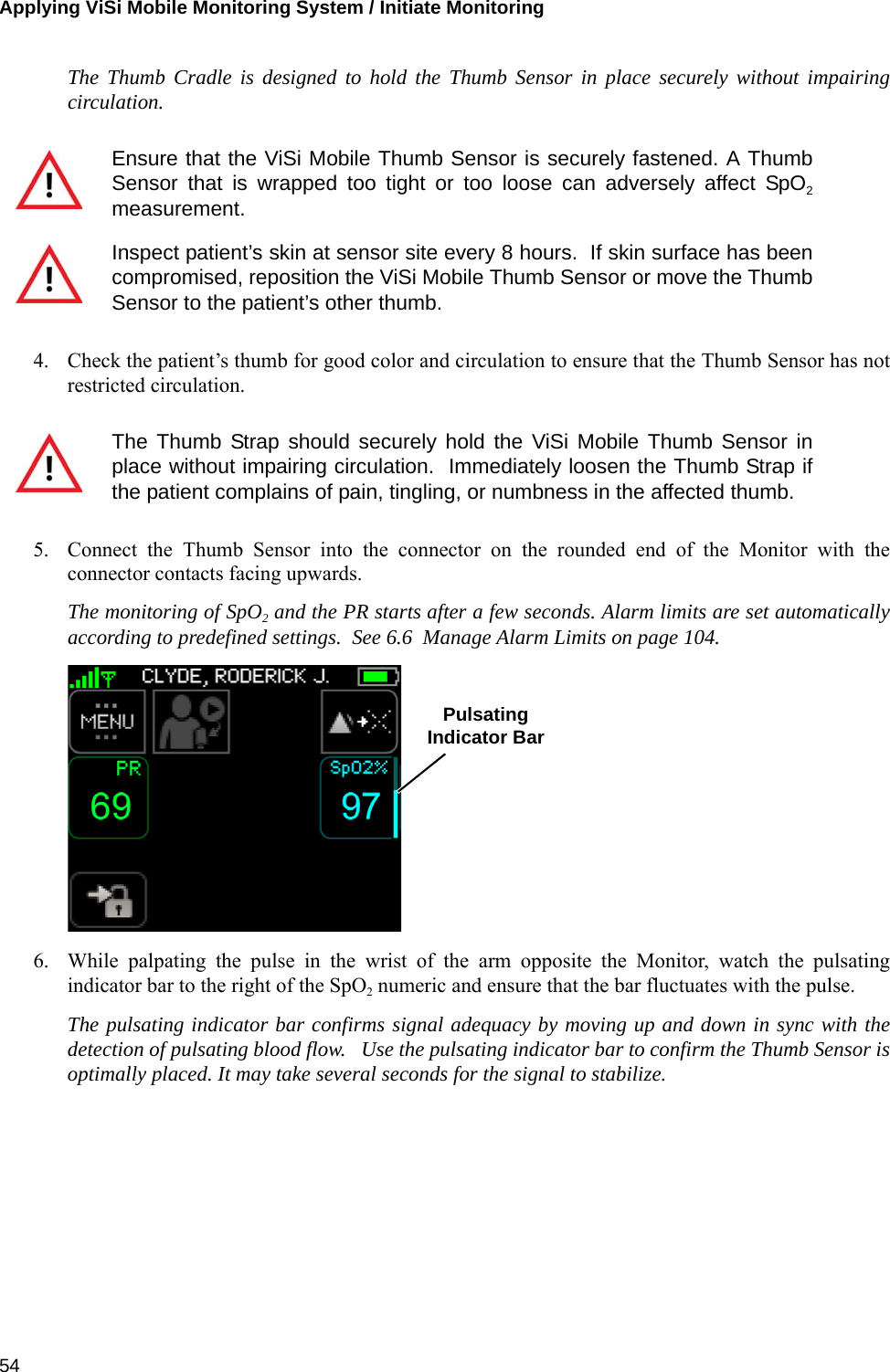
Sotera Wireless
>
VISI-MOBILE User Manual
>
User manual
Contents
1.
User manual
2.
User Manual
User manual
Navigation menu
Upload a User Manual
Namespaces
Wiki Guide
HTML
PDF
Info
Views
User Manual
Discussion / Help
Navigation

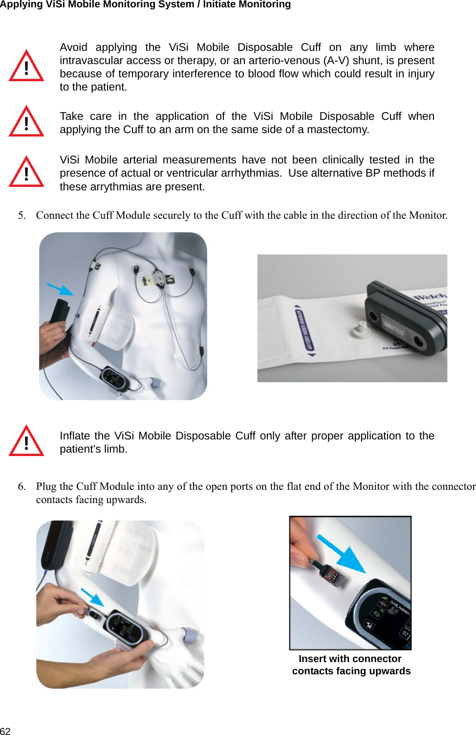
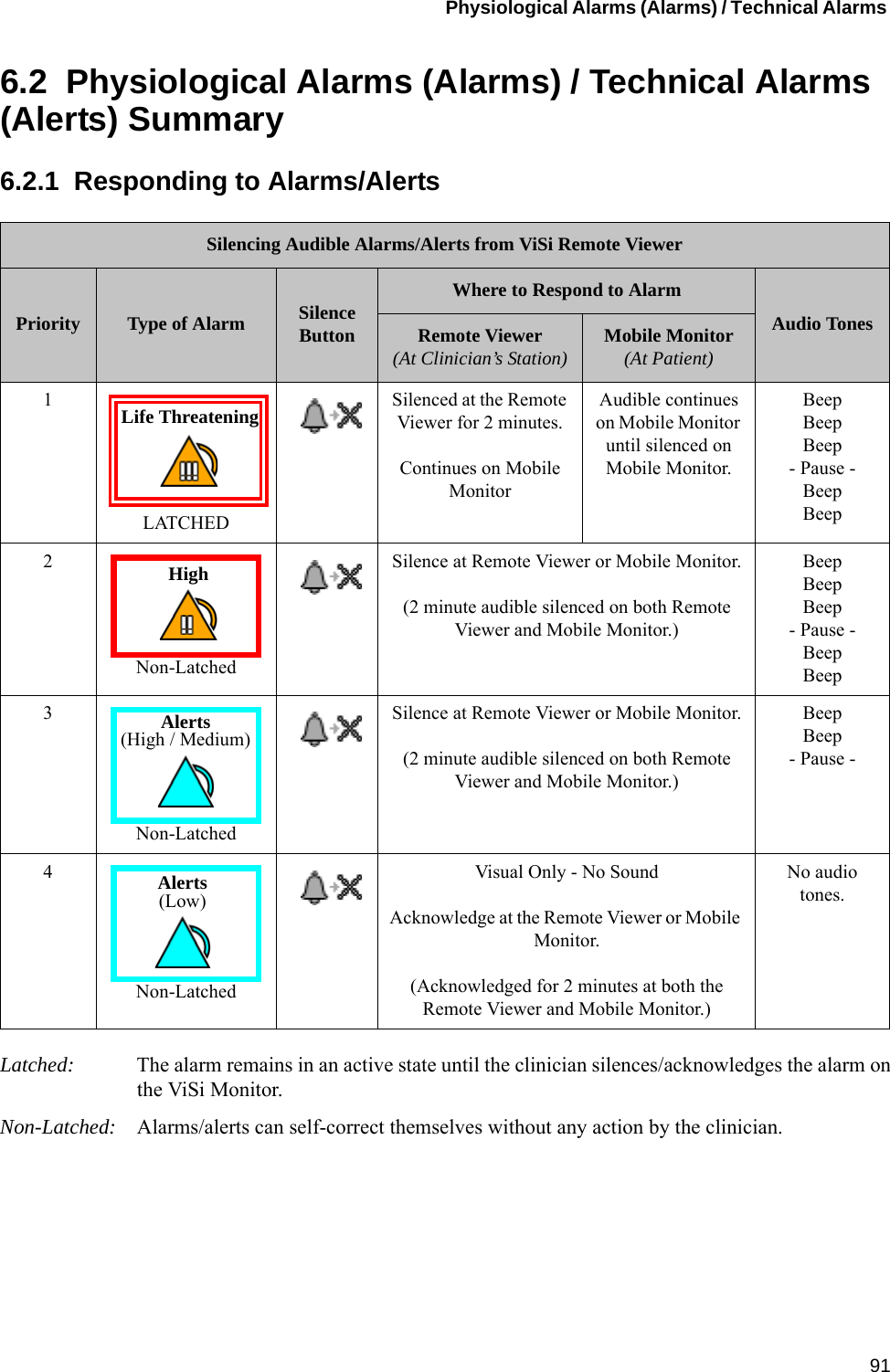

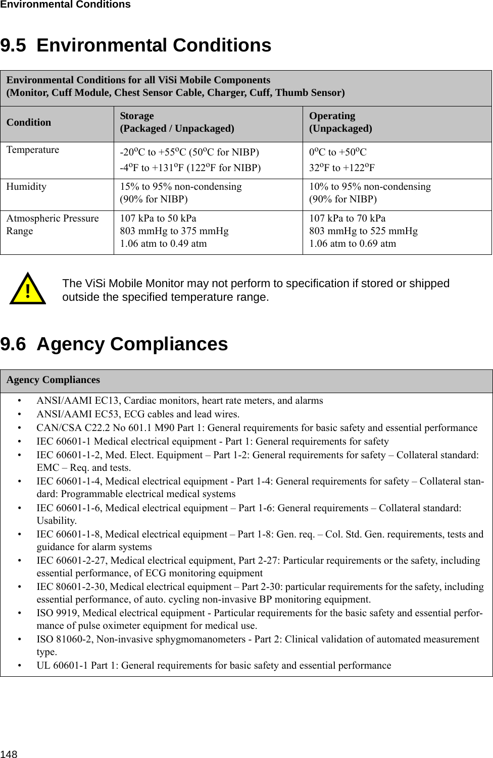
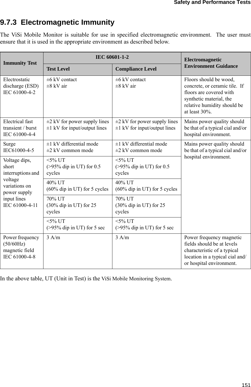
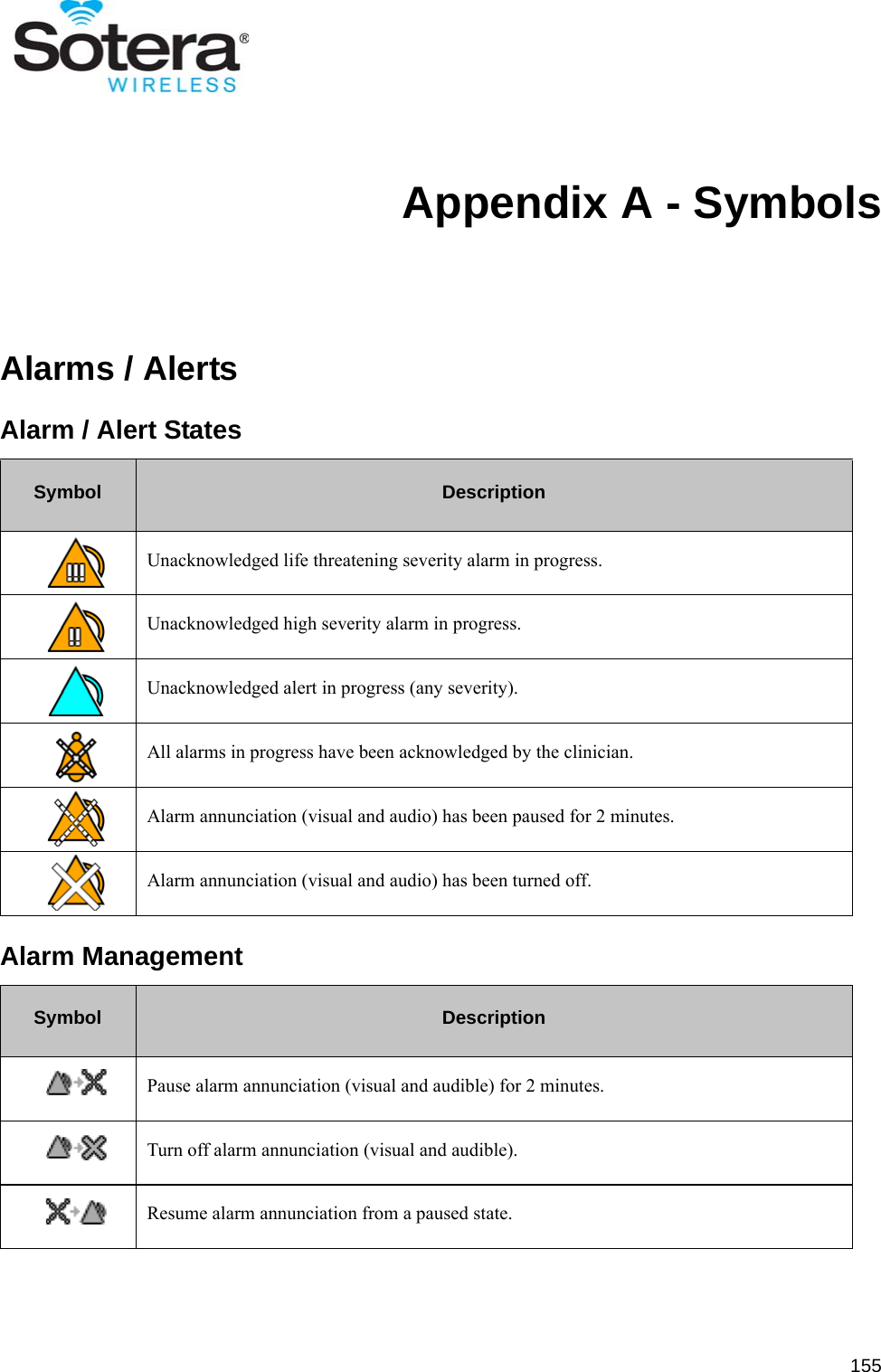
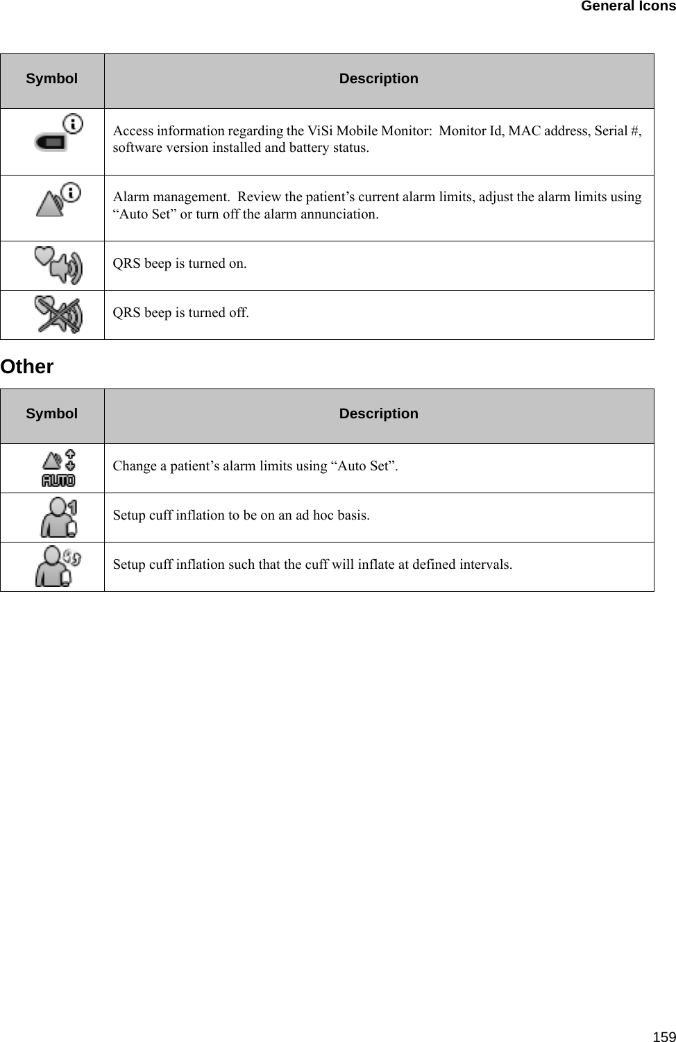
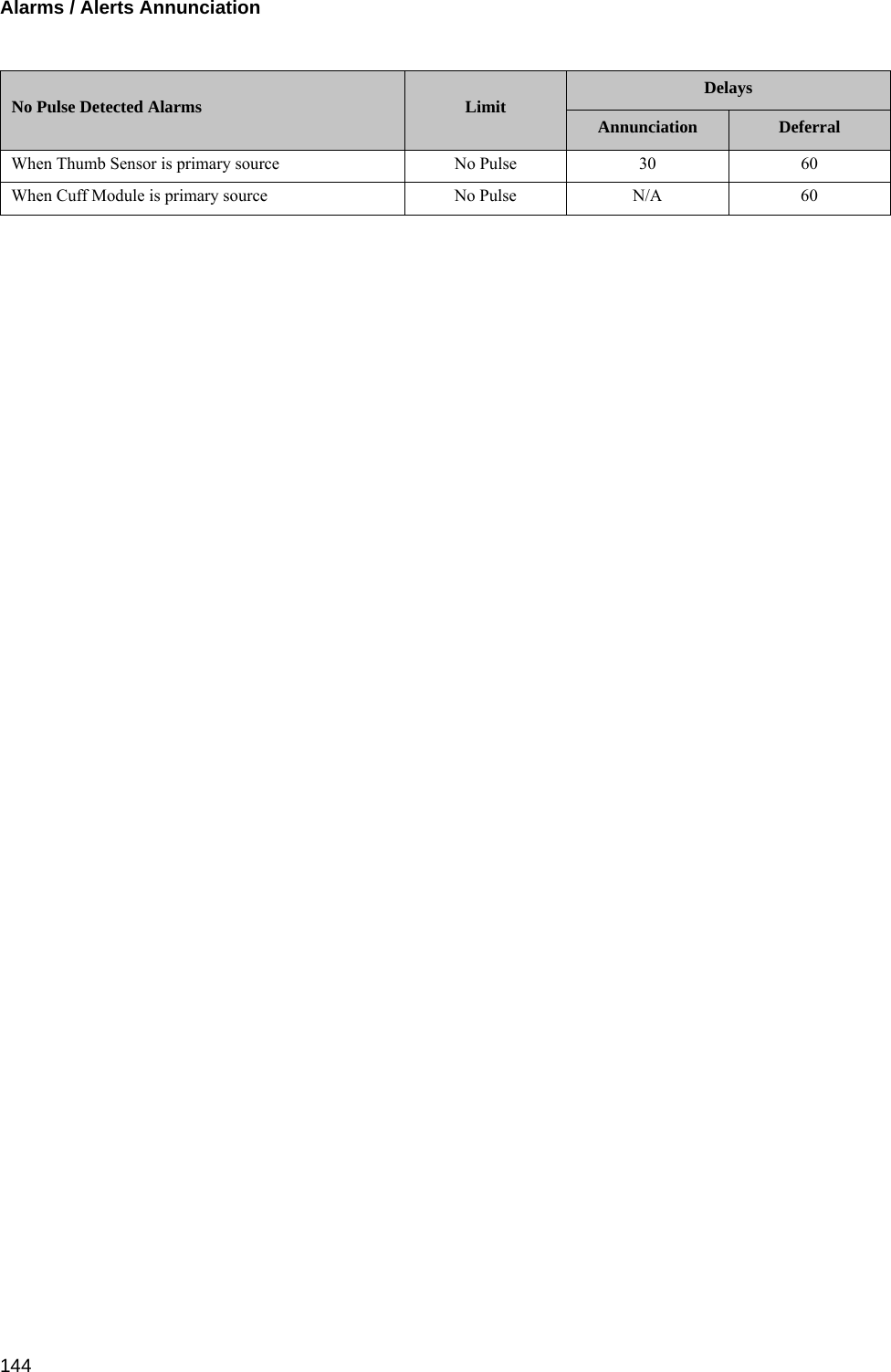
![Alarms / Alerts Annunciation1439.4 Alarms / Alerts AnnunciationNote: When the ViSi Mobile Monitor is connected to a network (as indicated by the networksymbol in the top left hand corner of the display), the audio annunciation of non-life-threatening alarms/alerts will be deferred to the Remote Viewer for a pre-configured periodof time. Within the tables below, see column “Deferral Delays” for the pre-defined periods oftime.9.4.1 Physiological Alarms (Alarms)Visual DisplayThe following table outlines the visual display when alarms are in progress:Audio TonesThe following table outlines the audio tones when alarms are in progress:Alarm Limits and Delays (factory default settings)Severity Indicator Attributes Toggle / Flash Speed Duty CycleHigh Priority Red 1.5Hz 50% ONLife-Threatening Priority Red / White 1.5Hz 50% ONSeverity Melodyaa. Melodies are defined as musical notes.Volume[db] Frequency(fo) [Hz] Duration(td) [ms] Spacing(ts) [ms] 5th-6th[s] Inter-Burst(tb) [s]Life Threatening b5.b5.b5..b5.b5 78 987.767 100 50 0.35 2.5High b5.b5.b5..b5.b5 78 987.767 200 100 0.35 5Vital Sign Lower Limit Upper Limit Annunciation Delay Deferral DelayCare Unit Patient Patient Care Unit Patient Care Unitaa. As the vital sign measurement approaches the care unit limit, the annunciation delay will decrease lin-early.Critical Low HR 18 18 N/A N/A N/A N/A N/AHeart Rate 30 40 140 160 N/A N/A 60Pulse Rate 30 40 140 160 30 30 60BP Systolic 70 90 190 240 N/A N/A 60BP Diastolic 40 50 120 150 N/A N/A 60Respiration 5 6 35 40 120 30 60SpO2 N/A N/A 85 85 30 30 60Skin Temp N/A N/A N/A N/A N/A N/A N/A](https://usermanual.wiki/Sotera-Wireless/VISI-MOBILE.User-manual/User-Guide-1750411-Page-143.png)
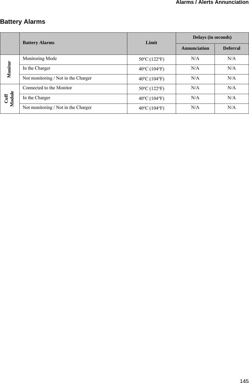
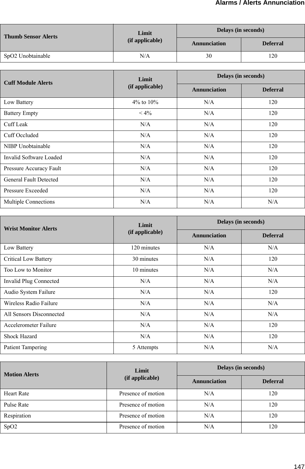
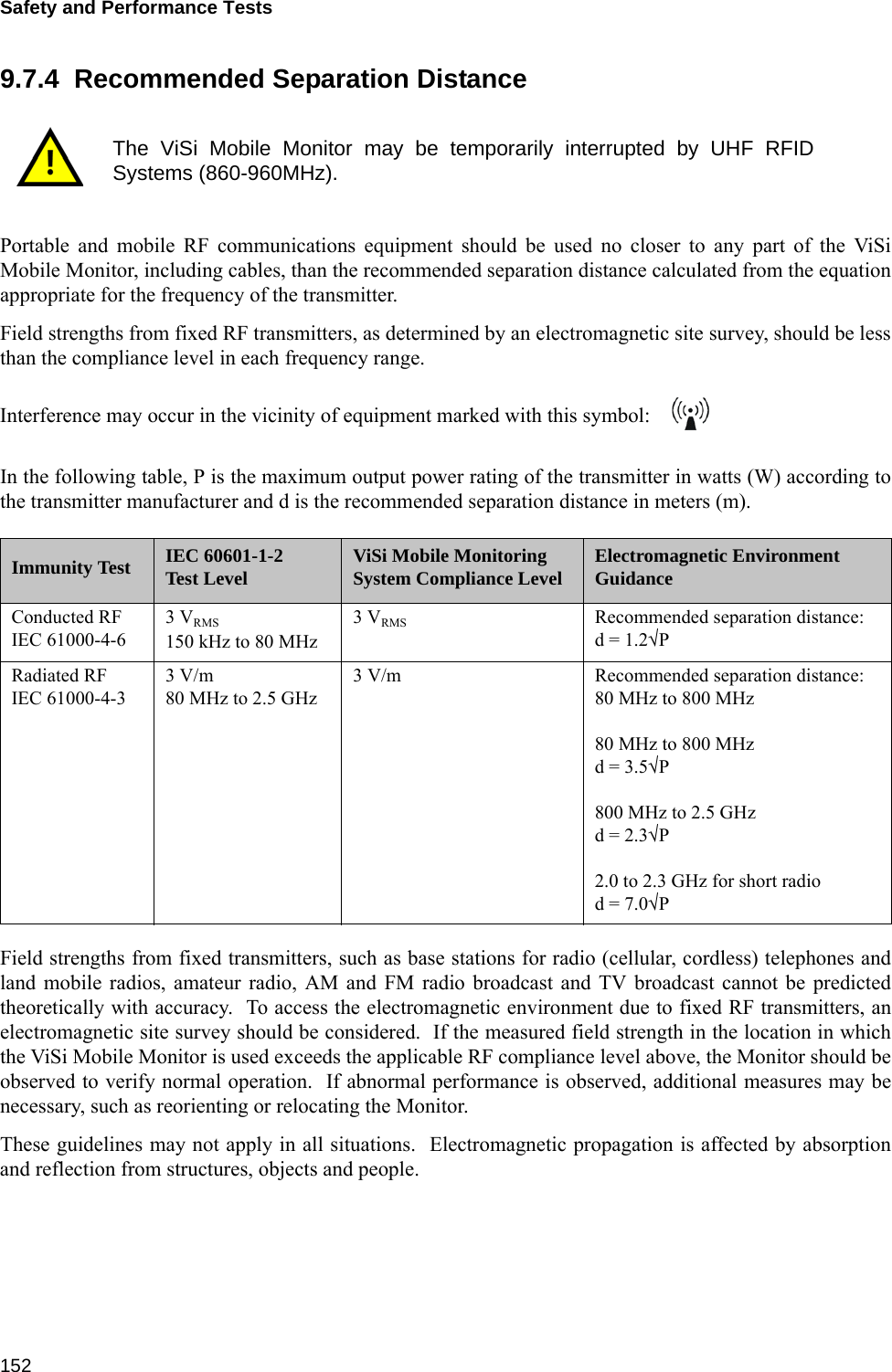
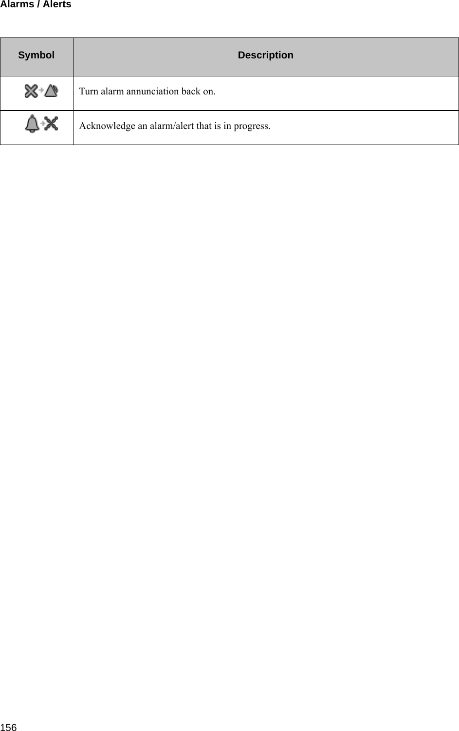
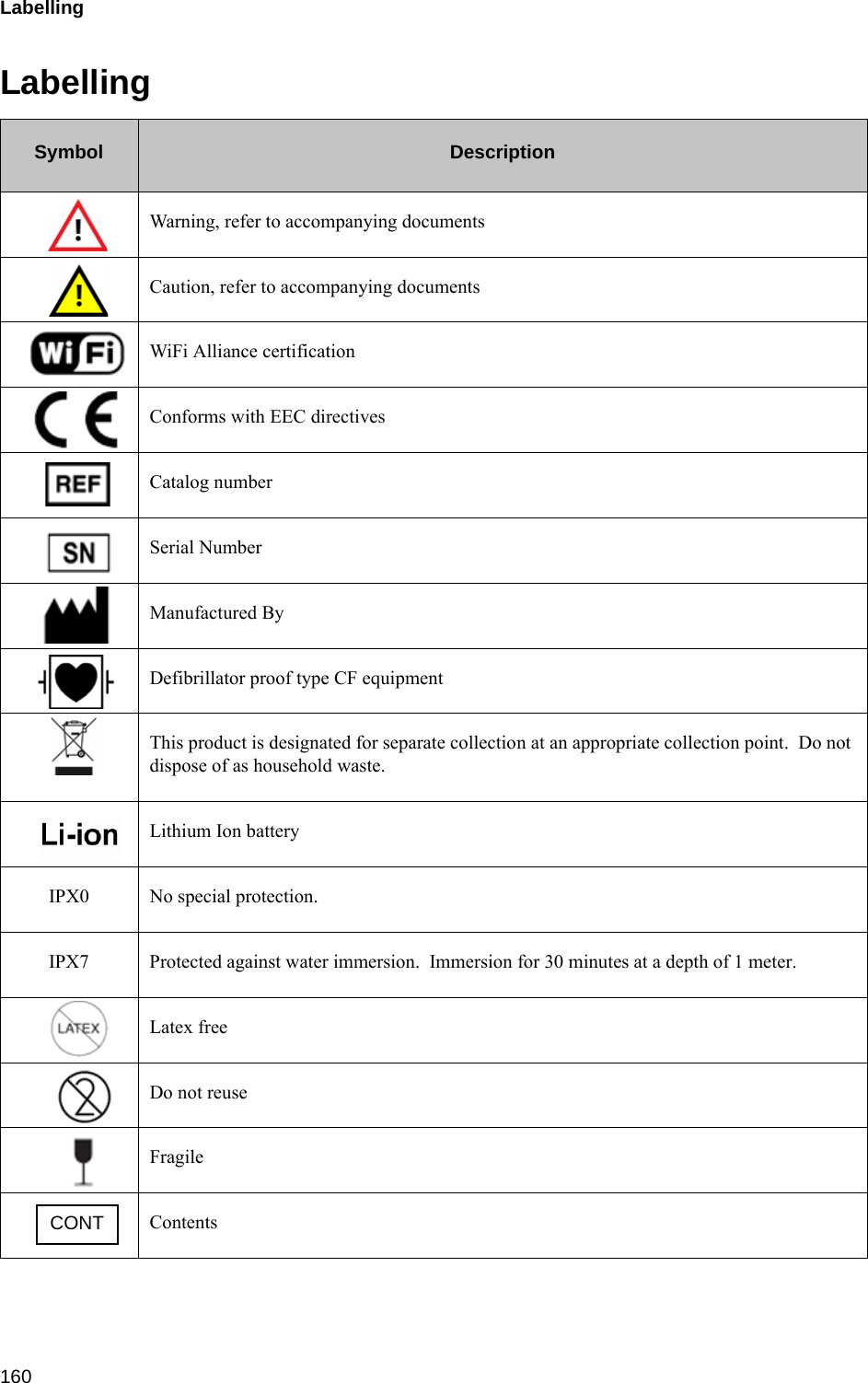
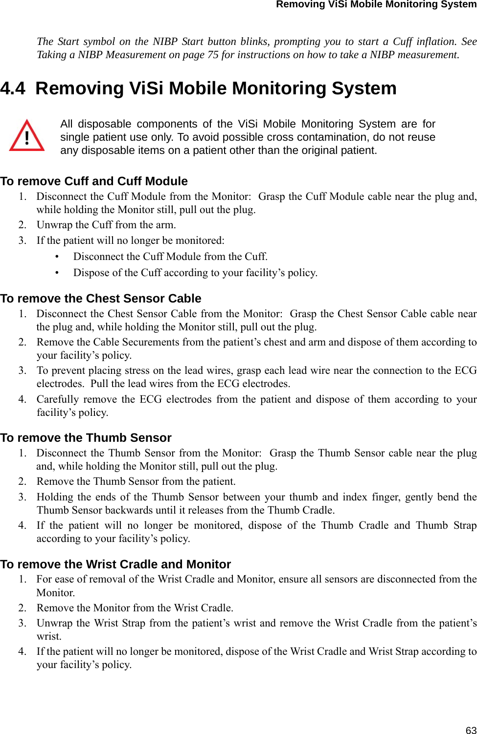
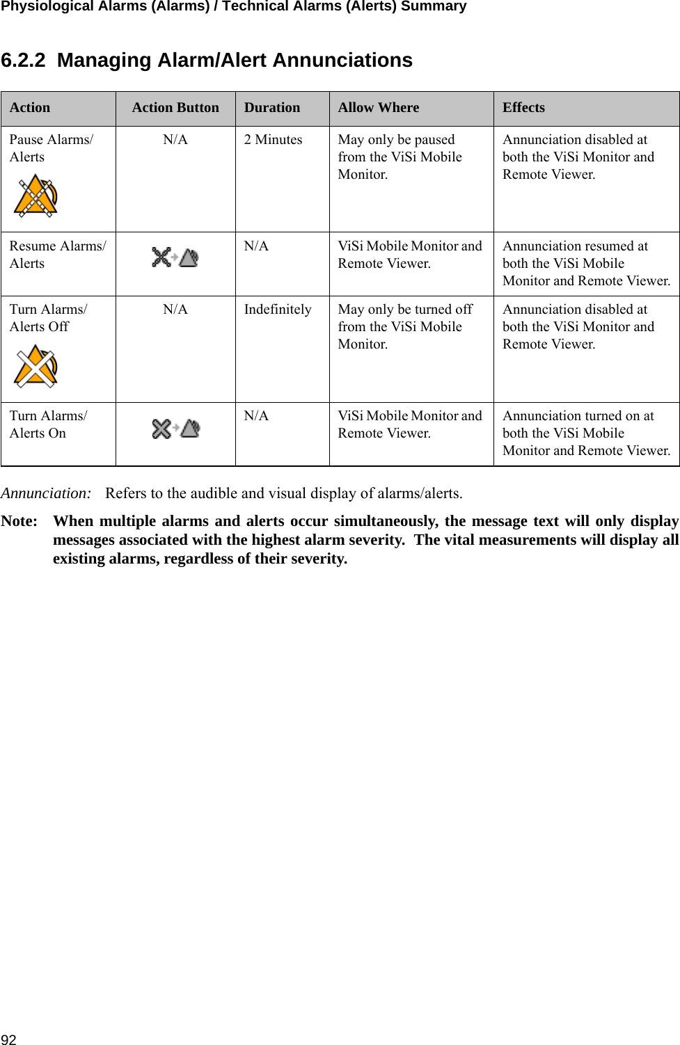
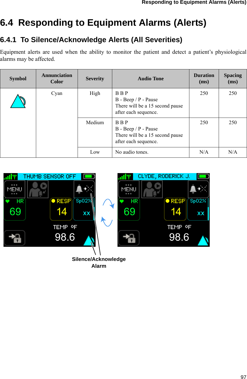
![Alarms / Alerts Annunciation 1469.4.2 Equipment Alarms (Alerts)Visual DisplayThe following table outlines the visual display when alerts are in progress:Audio TonesThe following table outlines the audio tones when alerts are in progress:Note: There are no audio tones associated with low severity alerts.Alarm Limits and Delays (factory default settings)Severity Indicator Attributes Toggle / Flash Speed Duty CycleAll Severities Cyan (Blue) Constant (ON) 100% ONSeverity Melodyaa. Melodies are defined as musical notes.Volume[db] Frequency(fo) [Hz] Duration(td) [ms] Spacing(ts) [ms] Inter-Burst(tb) [s]High e5.c5 68/63 659.255, 523.251 250 250 3Medium e5.c5 68/63 659.255, 523.251 250 250 15Chest Sensor Alerts Limit(if applicable)Delays (in seconds)Annunciation DeferralECG Lead Failure N/A N/A 120All ECG Lead Failure N/A N/A 120Chest Sensor Disconnected N/A N/A 120General Fault Detected N/A N/A 120Multiple Connections N/A N/A N/ATemperature Sensor Fault N/A N/A 120Accelerometer Fault - Chest Module N/A N/A 120Accelerometer Fault - Upper Arm N/A N/A 120Thumb Sensor Alerts Limit(if applicable)Delays (in seconds)Annunciation DeferralSpO2 Signal Lost N/A < 30 120Thumb Sensor Off N/A < 30 120Thumb Sensor Disconnected N/A N/A N/AThumb Sensor Failure N/A 30 120](https://usermanual.wiki/Sotera-Wireless/VISI-MOBILE.User-manual/User-Guide-1750411-Page-146.png)