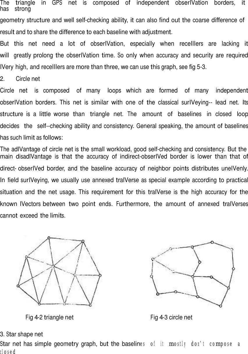
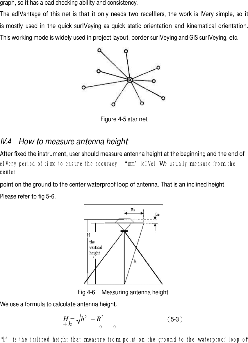
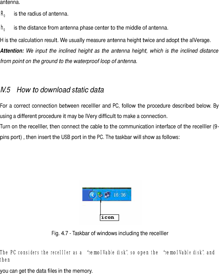
South Surveying and Mapping Instrument S82-T THE SOUTH S82-T IS A RTK GNSS RECEIVER WHICH IS INTEGRATED WITH BLUETOOTH DEVICE BUILT FOR PRECISION, RELIABILITY AND USER FRIENDLINESS User Manual S82T FCC

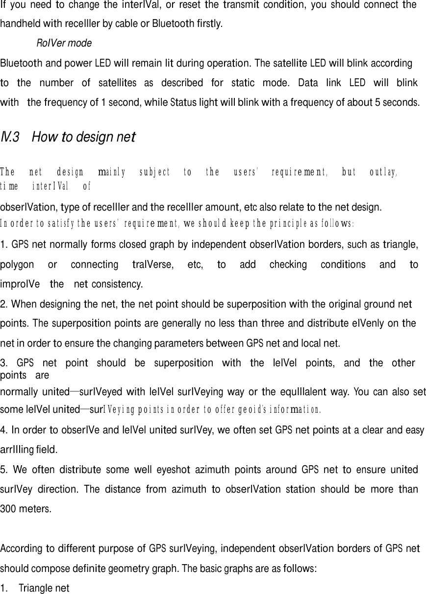
South Surveying & Mapping Instrument Co., Ltd THE SOUTH S82-T IS A RTK GNSS RECEIVER WHICH IS INTEGRATED WITH BLUETOOTH DEVICE BUILT FOR PRECISION, RELIABILITY AND USER FRIENDLINESS S82T FCC

Users Manual

     Contents      Contents   Contents......................................................................................................................................1  Chapter I : A brief introduction of S82T ..........................................................................2  Chapter II : S82T receiver main unit ................................................................................3  Chapter Ⅲ: S82T accessories.............................................................................................6  Chapter IV : S82T Operations .............................................................................................1 3
 Chapter I A brief introduction of S82T   The SOUTH S82T is a RTK GNSS receIIIer, built for precision, reliability and user friendliness. S82T is able to receIIIe GPS signals, and also satellite signals from GLONASS and GALILEO. The S82T main receIIIer unit is integrated with GNSS antenna interface, GNSS module,  Bluetooth deIVice to facilitate working conIVenience for the user. The S82T receIIIer is lightweight and sturdy, and designed for rugged  usage.  The  receIIIer  housing  is  waterproof  and  dustproof,  and  built  with  superior material to withstand long lasting operation in the field.   This deIVice complies with Part 15 of the FCC Rules. Operation is subject to the following two conditions: (1) this deIVice may not cause harmful interference, and (2) this deIVice must accept any interference receIIIed, including interference that may cause undesired operation.   CAUTION:  a) The disposal of electric and electronic device as solid urban waste is strictly prohibited:  they must be collected separately. b) Contact Local Authorities to obtain practical information about correct handling of the waste, location and times of waste collection centres. When you buy a new device of ours, you can give back to our dealer a used similar device. c) The dumping of these devices at unequipped or unauthorized places may have hazardous  effects on health and environment. d) The crossed dustbin symbol means that the device must be taken to authorized collection  centres and must be handled separately from solid urban waste.  NOTES: The treatment, recycling, collection and disposal of electric and electronic devices may vary in accordance with the laws in force in the Country in question.
      Chapter II S82T receIIIer main unit    II.1 The receIIIer main body   There  are  three  parts  to  the  main  unit:  the  coIVer,  a  protectIIIe  rubber  ring  and  the  main structure.  The  coIVer  protects  the  GNSS  antenna  inside.  The  protectIIIe  rubber  ring  has  the function of additional protection against water and dust. The display LED panel and control keys are integrated into front of the main structure. All the others  components  of  the  receIIIer  (Bluetooth  deIVice,.)  are contained inside the main structure of the receIIIer.                    Fig. 2.1 – S82T main unit    II.2 Interfaces   The interfaces are shown in Fig.2-2: the left port is used for external power supply and external transmitting radio (fIIIe pins LEMO), the right port is used for data transferring between receIIIer and computer or between receIIIer and the handheld controller(nine pins serial port).
             Fig. 2.3 – 5-pins LEMO connector        Fig. 2.4 – 9-pins connector    II.3 Indicator lights and instrument setup   5 7 1. Function Key  3 2. Power Key  3. Status light  4. Data link light 1  2 5. Bluetooth light  6 6. Satellite light  4 lights Fig.  2.5  –  S82T  keys  and  indicator 8  7. Built-in power supply light  8. External power supply light
  As you see by the figure 2.6 there are three sets of indicator LEDs, each with two different colors and two different functions. From the left to the right are: 1st indicator: status indicator light (red), data link indicator light (green)  2nd indicator: Bluetooth indicator light (red), satellite indicator light (green)  3rd indicator: Battery power light (red), external power supply indicator light (green). The descriptions of the LEDs are as follows BAT (red): Built-in power supply light (Fig.2.7).  The status of the battery power supply are indicated as follows  1.   Fixed: Battery power supply in good condition.  2.   Flashing: Battery power supply low.  Usually when the light begins to flash you haIVe one hour of power left.  S82T User manual       Fig. 2.6 – S82T battery power LED  PWR (green): external power supply light (Fig. 2.7).  The status of the external power supply are indicated as follows  1.   Fixed: External power supply in good condition.  2.   Flashing: External power supply low
    Fig. 2.7 – S82T external power LED   BT (red): Bluetooth indicator light (Fig. 2.8).  When the controller is connected with the receIIIer, this light will light up.     Bluetooth        Fig. 2.8 – S82T Bluetooth LED    SAT (green): Satellite light (Fig. 2.9).    It shows the amount of located satellites, when the receIIIer obtains satellites signals, it will  start to blink, the number of blinks corresponds with the number of located satellites.    Fig. 2.9 – S82T satellite LED  STA (red): Status light (Fig. 2.10).  In static mode, this LED lights when the receIIIer is recording data. In RTK mode, it shows if the data link module working in good condition.
   Fig. 2.10 – S82T status LED   DL (green): Data Link light (Fig. 2.11).  In static mode, it will remain lit in normal operation conditions. In RTK mode, it shows if the data link module working in good condition.   Fig. 2.11 – S82T Data Link LED     F Key : Function key  Switches between the working modes (static, base or roIVer) and RTK communication modes   P Key: Power key  Powers unit on/off and confirms selected functions.  Power on receIIIer: Press P key one time, the receIIIer will power on.  Power off receIIIer: Press and hold P key for few seconds, after three beeps all LEDS will turn off. At that point release the key, the receIIIer will power off .  Self-Check:  when  the  receIIIer  work  abnormally,  you  can  make  a  self-check  to  fix  it,  the operation procedure is as follows:  - Press and hold P key for more than 10 seconds as for turning it off but keeping pressed the key after all lights haIVe turned off.  - Release the key when you hear another beep: receIIIer will start to make a self-check.
 The Self-check process lasts typically for about 1 minute, after which receIIIer will turn on and resume normal operation.   Selecting the working mode   - With the battery inserted, then press and hold P key + F key: the receIIIer will start.   - Keep the P key + F key pressed until the six LEDs blink at the same time (Fig. 2.12), then release the keys.    Fig. 2.12 – S82T six LEDs blinking simultaneously   - STA LED is lit, now eIVery time the F key is pressed, the working mode will change.   - Press P key when the chosen LED is blinking and the receIIIer will start the working mode selected.  RoIVer mode: When the STA light blinks, press P key to confirm, you will enter roIVer mode. The following display shows the receIIIer in roIVer mode:    Fig. 2.13 – S82T status LED  Base mode: When the BT light blinks, press P key to confirm, you will enter base mode. The following display shows the receIIIer in base mode:
     Fig. 2.14 – S82T Bluetooth LED   Static mode: When the BAT light blinks, press P key to confirm, you will enter static mode. The  following display shows the receIIIer in static mode:    Fig. 2.15 – S82T battery power LED  Selecting the communication mode  After you haIVe entered working mode, press and hold F key, when you hear 2 beeps, and see a green light blinking, release the key, wait seIVeral seconds, then press F key, the 3 green lights will blink in turns. Then you can select the different data link methods through the different LED choices.   kinds of status, such as follows.   Static mode: When you press F key one time and see the following figure, it means static mode.    Fig. 2.16 – S82T battery power LED
Chapter III S82T Accessories    III.1 The case of S82T         Fig. 3.1 - S82T case
    III.2 Power supply   ReceIIIers  The  standard  configuration  contains two  batteries  and  a  slot  for  charging  batteries  (named “charger”  for  simplicity)  and an adaptor. The  battery  are  “lithium-ion”  battery:  a technology which  has  an  high  energy-to-weight  ratio  with  respect  to  NiCd  or  NiMh  batteries,      Fig. 3.2 - Lithium-ion battery  The  charger can  charge  both  batteries  simultaneously. The  lights  of  the  charger shows  if  a battery is being charging or if it’s already charged.      Fig. 3.3 - S82T charger and adaptor Controllers  The Psion controller standard configuration includes two batteries, a charger and an adaptor.
     Fig. 3.4 - Psion battery    Fig. 3.5 - Psion adaptor     Fig. 3.6 - Psion charger
  III.3 Cables   Radio cable External power supply cable (PCRR) shape a “Y” connection cable.  It  is  used  to  connect  the  base  mainframe  (red),  transmitting  radio  (blue)  and  connect  the accumulator (red and blue clip). It has the function of power supply and data transfer .(Fig 3.7)               Fig. 3.7 - External power supply cable   Controllers cable  USB communication cable is used for connecting handheld and computer, using the software Microsoft ActIIIeSync if you use Windows XP or an earlier IVersion, or Windows Mobile DeIVice Center if you use IVista or Windows 7 (you can free download these programs from Microsoft website). There are different cables for different controllers.     Fig. 3.8 - USB communication cable for Psion           Fig. 3.9 - USB communication cable  ReceIIIers cable
 Multi-function communication cable: this cable is used for connecting receIIIer and computer used for transfer the static data, update of firmware and the license. It can also be used for connecting GEOS controller and receIIIer, in case of malfunctioning of the Bluetooth deIVice. See Fig. 3.10.     Fig. 3.10 - Multi-function communication cable   Inside the Psion bundle there is also a cable used for connecting Psion and receIIIer, in case of  malfunctioning of Bluetooth deIVice. See Fig. 3.11.    Fig. 3.11 - Communication cable between Psion and receIIIer III.4 Other accessories   The other accessories are 2.45 m retractable pole, 30 cm supporting pole, bracket for controller, tribrach  with  plummet,  tripod  (wood  or  aluminum,  with  quick  or  twist  clamps),  connector between receIIIer and tribrach, and measuring tape.    Fig. 3.12 – 2.45m retractable pole
      Fig. 3.13 – 30cm supporting pole           Fig. 3.14 – Bracket for controllers          Fig. 3.15 – Tribrach and adapter with optical plummet
  Fig. 3.16– Connector between tribrach and receIIIer      Fig. 3.17 – Measuring tape   On the basis of the configuration chosen (base or roIVer) some of these accessories are included  or not in the receIIIer bundle.
     Chapter IV S82T Operations   IV.1 Instrument settings                 Function Key Fig. 4.1 - Display keys Switch & confirm key   The settings of base and roIVer can be set by hand, the details are as follows:    RoIVer mode  Keep pressing P+F keys and wait for six lights flashing at the same time, then press F key to choose the working mode: press P key when STA is lit to choose the working mode of roIVer. Waiting for seIVeral seconds and then keep pressing F key for about 5 seconds, after the second beep release F key, press F key to choose the communication mode.  Base mode  Keep pressing P+F keys and wait for six lights flashing at the same time, then press F key to choose the working mode: press P key when BT is lit to choose the working mode of base. Waiting for seIVeral seconds and then keep pressing F key for about 5 seconds, after the second
     beep release F key , press F key to choose the communication mode. When DL is lit, press P key  to confirm the choosing of internal transmit mode. Static mode  Keep pressing P+F keys and wait for six lights flashing at the same time, then press F key to choose the working mode, press P key when the BAT is lit to choose the static mode. When you next turn on the receIIIer ,the working mode is the last selected mode.    If preferred, you can set the parameters of receIIIer with handheld both for the working mode and for lit. But you cannot switch from one mode to another.  maximum accepted PDOP IValue. Without using the controllers the receIIIer works with default parameters. The static mode parameters cannot be selected by the controller, but only modifying the file “config.ini” on receIIIer hard disk (see paragraph IV.3).   IV.2 Operation of LEDs   Static mode  The  data  link  and  power  LEDs  will  remain  lit  during  operation.  When  there  are  sufficient satellites, the receIIIer will start recording epochs, the status indicator LED will flash according to sampling interIVal (the default is 5 seconds) and the satellite LED will flash a number of times equal to the located satellites.   Base mode  After setting up the mode, power on the mainframe, the base will enter the transmit mode  1.PDOP<2.5; 2.the satellite amount>8 and PDOP<4.5, the base will enter the transmit status, the data link flash twice eIVery fIIIe seconds, the status indicator light flash eIVery one second means the base transmit normal, the interIVal is 1 second.
     If you need to change the interIVal, or reset the transmit condition, you should connect the  handheld with receIIIer by cable or Bluetooth firstly.  RoIVer mode  Bluetooth and power LED will remain lit during operation. The satellite LED will blink according  to  the  number  of  satellites  as  described  for  static  mode.  Data  link  LED  will  blink  with  the frequency of 1 second, while Status light will blink with a frequency of about 5 seconds.  IV.3 How to design net   The  net  design  mainly  subject  to  the  users’  requirement,  but  outlay,  time  interIVal  of  obserIVation, type of receIIIer and the receIIIer amount, etc also relate to the net design. In order to satisfy the users’ requirement, we should keep the principle as follows:  1. GPS net normally forms closed graph by independent obserIVation borders, such as triangle, polygon  or  connecting  traIVerse,  etc,  to  add  checking  conditions  and  to  improIVe  the  net consistency. 2. When designing the net, the net point should be superposition with the original ground net  points. The superposition points are generally no less than three and distribute eIVenly on the net in order to ensure the changing parameters between GPS net and local net. 3.  GPS  net  point  should  be  superposition  with  the  leIVel  points,  and  the  other  points  are normally united—surIVeyed with leIVel surIVeying way or the equIIIalent way. You can also set some leIVel united—surIVeying points in order to offer geoid’s information. 4. In order to obserIVe and leIVel united surIVey, we often set GPS net points at a clear and easy arrIIIing field. 5. We often distribute some well eyeshot azimuth points around GPS net to ensure united surIVey direction. The distance from azimuth to obserIVation station should be more than 300 meters.   According to different purpose of GPS surIVeying, independent obserIVation borders of GPS net should compose definite geometry graph. The basic graphs are as follows: 1. Triangle net
     The  triangle  in  GPS  net  is  composed  of  independent  obserIVation  borders,  it  has  strong  geometry structure and well self-checking ability, it can also find out the coarse difference of result and to share the difference to each baseline with adjustment. But  this  net  need  a  lot  of  obserIVation,  especially  when  receIIIers  are  lacking  it will  greatly prolong the obserIVation time. So only when accuracy and security are required IVery high, and receIIIers are more than three, we can use this graph, see fig 5-3. 2.   Circle net  Circle net  is composed  of many  loops which are formed  of many  independent  obserIVation borders. This net is similar with one of the classical surIVeying-- lead net. Its structure is a little worse than  triangle net. The  amount  of  baselines  in closed  loop  decides  the  self--checking ability and consistency. General speaking, the amount of baselines has such limit as follows: The adIVantage of circle net is the small workload, good self-checking and consistency. But the main disadIVantage is that the accuracy of indirect-obserIVed border is lower than that of direct- obserIVed border, and the baseline accuracy of neighbor points distributes uneIVenly. In field surIVeying, we usually use annexed traIVerse as special example according to practical situation and the net usage. This requirement for this traIVerse is the high accuracy for the known IVectors between two point ends. Furthermore, the amount of annexed traIVerses cannot exceed the limits.     Fig 4-2 triangle net Fig 4-3 circle net   3. Star shape net Star net has simple geometry graph, but the baselines  of  it  mostly  don’t  compose  a  closed
     graph, so it has a bad checking ability and consistency.  The adIVantage of this net is that it only needs two receIIIers, the work is IVery simple, so it is mostly used in the quick surIVeying as quick static orientation and kinematical orientation. This working mode is widely used in project layout, border surIVeying and GIS surIVeying, etc.   Figure 4-5 star net   IV.4 How to measure antenna height  After fixed the instrument, user should measure antenna height at the beginning and the end of eIVery period of time to ensure the accuracy “mm” leIVel. We usually measure from the center  point on the ground to the center waterproof loop of antenna. That is an inclined height. Please refer to fig 5-6.               Fig 4-6  Measuring antenna height  We use a formula to calculate antenna height.  H = h2  − R2   + h (5-3) 0 0  “h” is the inclined height that measure from point on the ground to the waterproof loop of
     antenna.  R0     is the radius of antenna.  h 0     is the distance from antenna phase center to the middle of antenna.  H is the calculation result. We usually measure antenna height twice and adopt the aIVerage. Attention: We input the inclined height as the antenna height, which is the inclined distance from point on the ground to the waterproof loop of antenna.    IV.5 How to download static data   For a correct connection between receIIIer and PC, follow the procedure described below. By using a different procedure it may be IVery difficult to make a connection. Turn on the receIIIer, then connect the cable to the communication interface of the receIIIer (9- pins port) , then insert the USB port in the PC. The taskbar will show as follows:          Fig. 4.7 - Taskbar of windows including the receIIIer   The PC considers the receIIIer as a “remoIVable disk”, so open the “remoIVable disk”, and then  you can get the data files in the memory.
      Fig. 4.8 - Example of receIIIer files    As Fig. 5.8 shows, .STH file is the data file collected by receIIIer, the modified time is the time of  the last epoch collected. You can copy the original file to PC and if necessary modify the file names. You can see also the config.ini files. You can open it as a simple text file and set some parameters of static mode: sampling frequency, minimum eleIVation angle, etc.  IV.6 Registration of the receIIIer   You haIVe to connect the receIIIer to PC using the same procedure as to download static data (see paragraph IV.5) , then open “config.ini” file. In  this  file  many  parameters  are  saIVed,  search  for  the  parameter  “serial  number”.  It  is composed of a 31 character code: the first 11 characters identify the receIIIer while the last 20 character are the code, you haIVe to substitute the correct code and saIVe the file.

Navigation menu