Southbend P16C C Users Manual
P16C-T to the manual 207b37bd-d2cf-4bb4-bbb7-82efef1e1e68
2015-02-02
: Southbend Southbend-P16C-C-Users-Manual-447720 southbend-p16c-c-users-manual-447720 southbend pdf
Open the PDF directly: View PDF ![]() .
.
Page Count: 1
MANUAL 1185836 REV 3 (07/06)
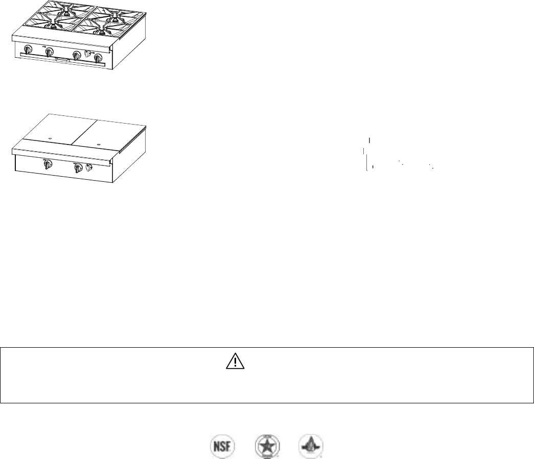
$18.00 PLATINUM SERIES SECTIONAL RANGE
MANUAL SECTION SR
Installation & Operation Manual
Platinum Series Sectional Range
WARNING
Improper installation, adjustment, alteration, service, or maintenance can cause property damage, injury, or death.
Read installation, operation, and maintenance instructions thoroughly before installing or servicing this equipment.
1100 Old Honeycutt Road, Fuquay-Varina, NC 27526 USA • www.southbendnc.com
Charbroiler Models: P16C-C, P16N-C, P24C-CC, P24N-CC, P32A-CC, P32C-CC, P32D-CC, P32N-CC, P36A-CCC, P36C-CCC, P36D-CCC,
P36N-CCC, P48A-CCCC, P48C-CCCC, P48D-CCCC, & P48N-CCCC
Standard Griddle Models: P16C-G, P16N-G, P32A-GG, P32C-GG, P32D-GG, P32N-GG, P48A-GGG, P48C-GGG, P48D-GGG, & P48N-GGG
Graduated Hot-Top Models: P32A-GRAD, P32C-GRAD, P32D-GRAD, & P32N-GRAD
Uniform Hot-Top Models: P16C-H, P16N-H, P32A-HH, P32C-HH, P32D-HH, & P32N-HH
Thermostatic Griddle Models: P16C-T, P16N-T, P32A-TT, P32C-TT, P32D-TT, P32N-TT, P48A-TTT, P48C-TTT, P48D-TTT, & P48N-TTT
Flush Open-Burner Models: P12C-B, P12N-B, P16C-X, P16N-X, P32A-BBB, P32A-XX, P32C-BBB, P32C-XX, P32D-BBB, P32D-XX,
P32N-BBB, P32N-XX, P48A-BBBB, P48D-BBBB, & P48N-BBBB
Step-Up Open-Burner Models: P32A-BBB-SU, P32C-BBB-SU, P32D-BBB-SU, P32N-BBB-SU
Combination Open-Burner Hot-Top Models: P32A-XH, P32C-XH, P32D-XH, P32N-XH, P32A-XH-RE, P32C-XH-RE, P32D-XH-RE, & P32N-XH-RE
Combination Open-Burner Griddle Models: P32A-XG, P32C-XG, P32D-XG, P32N-XG, P32A-XT, P32C-XT, P32D-XT, & P32N-XT
Wood Smoker: P36W-CCC, P48W-CCCC, P60W-CCCCC, P72W-CCCCCC
SAFETY PRECAUTIONS PLATINUM SERIES SECTIONAL RANGE
PAGE 2 OF 80 INSTALL & OPERATIONS MANUAL 1185836 REV 3 (07/06)
SAFETY PRECAUTIONS
Before installing and operating this equipment, be sure everyone involved in its operation is fully trained and aware of
precautions. Accidents and problems can be caused by failure to follow fundamental rules and precautions.
The following symbols, found throughout this manual, alert you to potentially dangerous conditions to the operator,
service personnel, or to the equipment.
DANGER This symbol warns of immediate hazards that will result in severe injury or death.
WARNING This symbol refers to a potential hazard or unsafe practice that could result in injury or
death.
CAUTION This symbol refers to a potential hazard or unsafe practice that could result in injury,
product damage, or property damage.
NOTICE This symbol refers to information that needs special attention or must be fully understood,
even though not dangerous.
WARNING
FIRE HAZARD
FOR YOUR SAFETY
Do not store or use gasoline or other flammable vapors and liquids in the vicinity of cooking appliances.
Keep area around cooking appliances free and clear of combustibles.
Purchaser of equipment must post in a prominent location detailed instructions to be followed in the event the
operator smells gas. Obtain the instructions from the local gas supplier.
WARNING
BURN HAZARD
Contact with hot surfaces will cause severe burns. Always use caution when operating cooking appliances.
WARNING
EXPLOSION AND ASPHYXIATION HAZARD
In the event a gas odor is detected, shut down equipment at the main gas shut-off valve and immediately call
the emergency phone number of your gas supplier.
Improper ventilation can result in headaches, drowsiness, nausea, and could result in death. Do not obstruct the
flow of combustion and ventilation air to and from cooking appliances.
WARNING
ELECTRIC SHOCK HAZARD
For appliances that use electric power, disconnect the power to the appliance before cleaning. Do not remove
panels that require tools to remove.
NOTICE
Southbend appliances are intended for commercial use only. Not for household use.
Warranty will be void if service work is performed by other than a qualified technician, or if other than genuine
Southbend replacement parts are installed.
Give this Owner’s Manual and important papers to the proper authority to retain for future reference.
Copyright © 2003 by Southbend. All rights reserved. Published in the United States of America.
PLATINUM SERIES SECTIONAL RANGE INTRODUCTION
INSTALL AND OPERATIONS MANUAL 1185836 REV 3 (07/06) PAGE 3 OF 80
INTRODUCTION
Congratulations! You have purchased one of the finest pieces of heavy-duty commercial cooking equipment on the
market.
You will find that your new equipment, like all Southbend equipment, has been designed and manufactured to meet
the toughest standards in the industry. Each piece of Southbend equipment is carefully engineered and designs are
verified through laboratory tests and field installations. With proper care and field maintenance, you will experience
years of reliable, trouble-free operation. For best results, read this manual carefully.
RETAIN THIS MANUAL FOR FUTURE REFERENCE.
This manual is for Southbend Platinum Series Sectional Range models P12C-B, P12N-B, P16C-C, P16C-G, P16C-H,
P16C-T, P16C-X, P16N-C, P16N-G, P16N-H, P16N-T, P16N-X, P24C-CC, P24N-CC, P32A-BBB, P32A-BBB-SU,
P32A-CC, P32A-GG, P32A-GRAD, P32A-HH, P32A-TT, P32A-XG, P32A-XH, P32A-XH-RE, P32A-XT, P32A-XX,
P32C-BBB, P32C-BBB-SU, P32C-CC, P32C-GG, P32C-GRAD, P32C-HH, P32C-TT, P32C-XG, P32C-XH,
P32C-XH-RE, P32C-XT, P32C-XX, P32D-BBB, P32D-BBB-SU, P32D-CC, P32D-GG, P32D-GRAD, P32D-HH,
P32D-TT, P32D-XG, P32D-XH, P32D-XH-RE, P32D-XT, P32D-XX, P32N-BBB, P32N-BBB-SU, P32N-CC, P32N-GG,
P32N-GRAD, P32N-HH, P32N-TT, P32N-XG, P32N-XH, P32N-XH-RE, P32N-XT, P32N-XX, P36A-CCC, P36C-CCC,
P36D-CCC, P36N-CCC, P48A-BBBB, P48A-CCCC, P48A-GGG, P48A-TTT, P48C-BBBB, P48C-CCCC, P48C-GGG,
P48C-TTT, P48D-BBBB, P48D-CCCC, P48D-GGG, P48D-TTT, P48N-BBBB, P48N-CCCC, P48N-GGG, P48N-TTT,
P36W-CCC, P48W-CCCC,P60W-CCCCC AND P72W-CCCCCC.
This manual does NOT cover Southbend sectional fryers, fryer filter systems, salamander broilers, upright broilers,
cheese melters, or refrigerated bases. Those appliances have their own manuals.
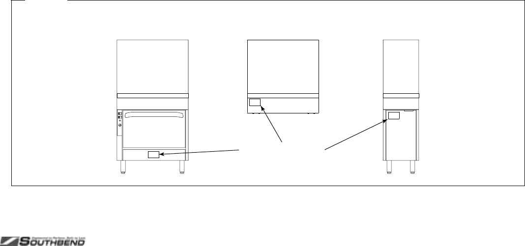
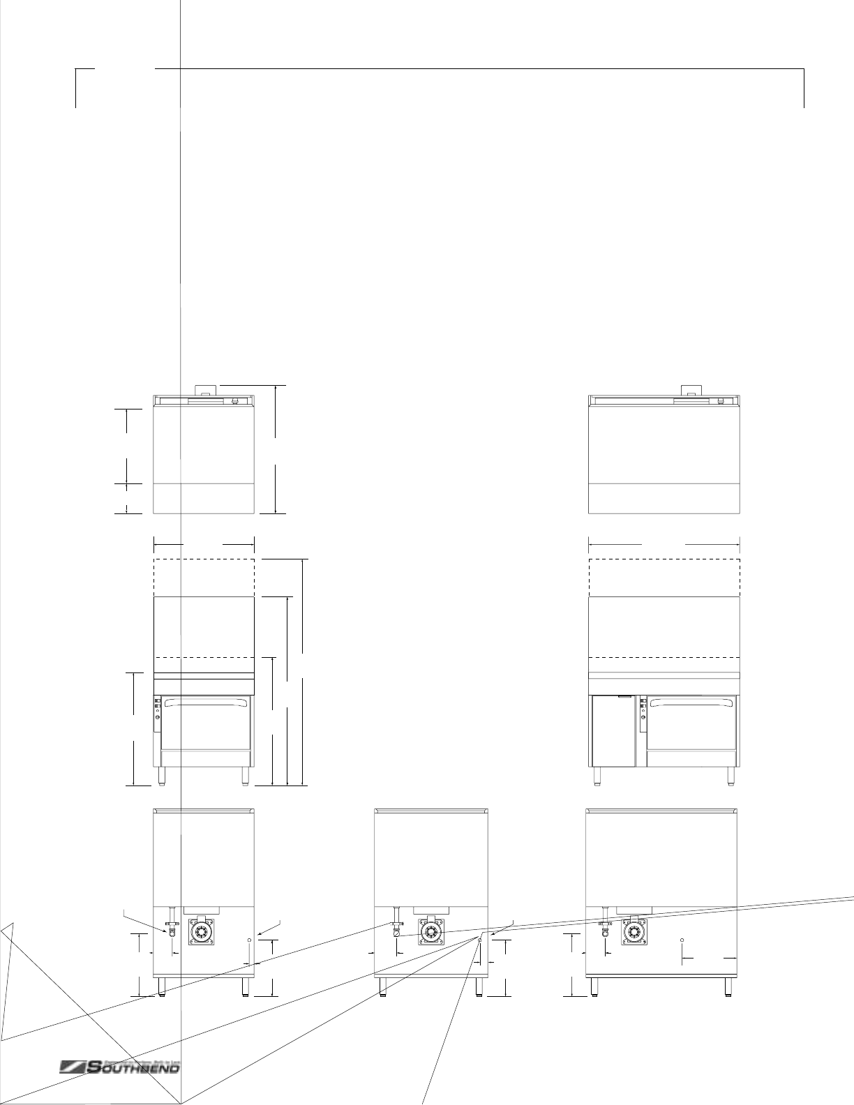
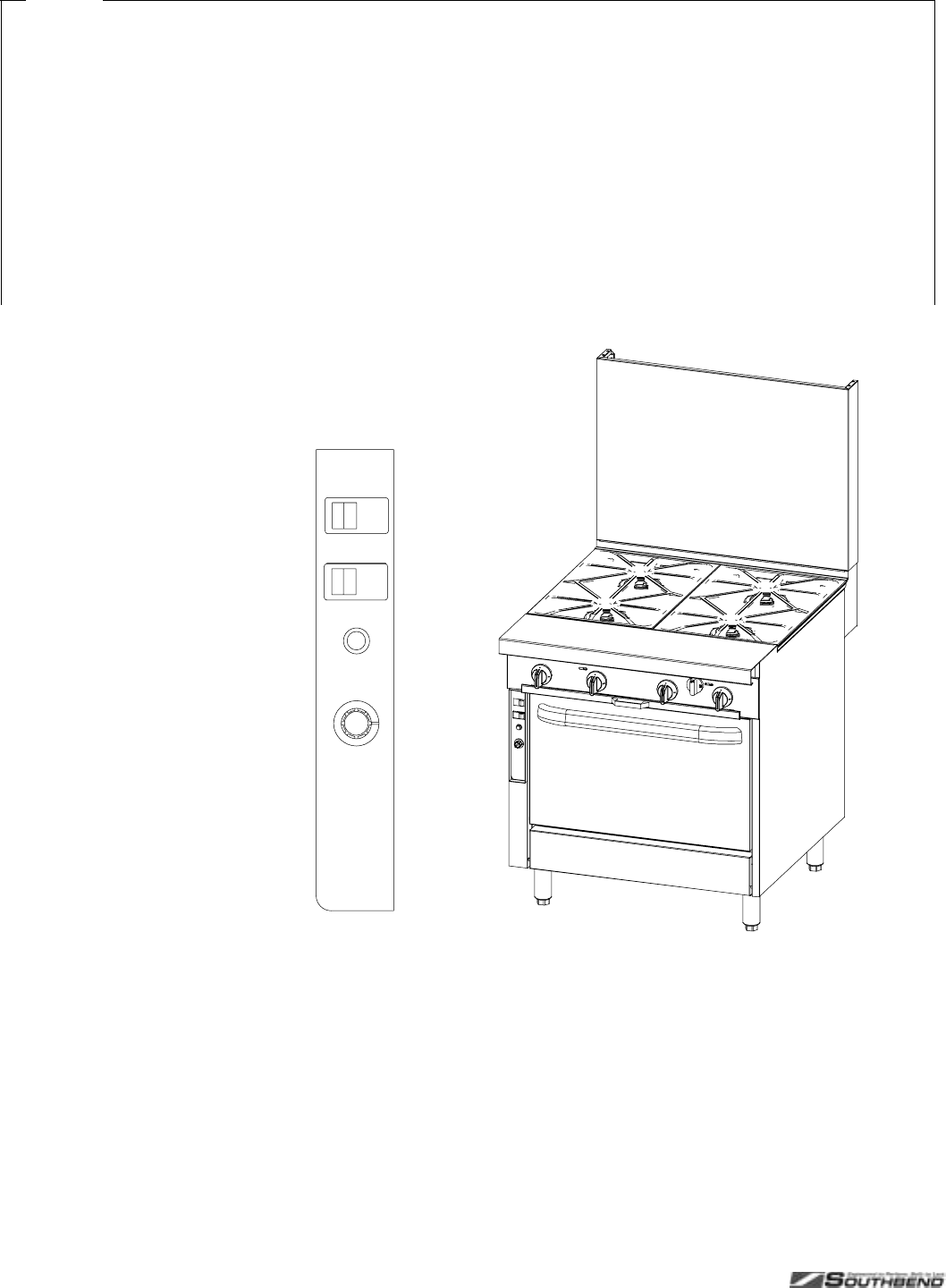
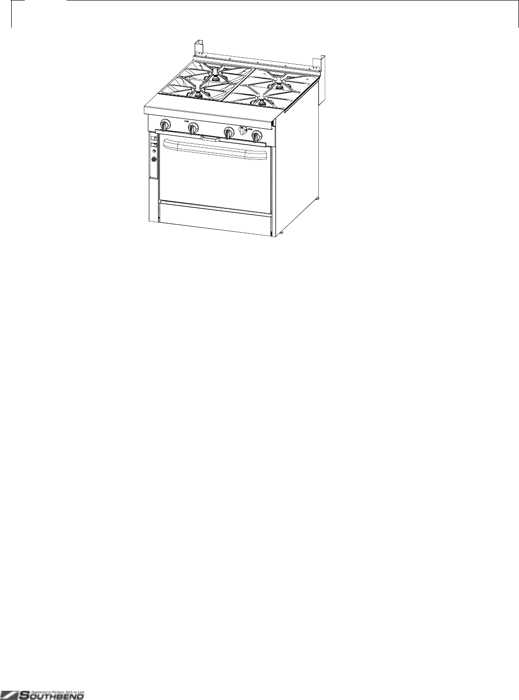
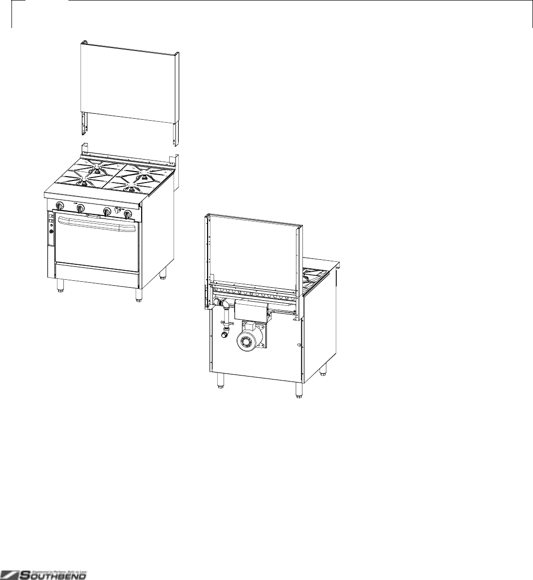
The location of the serial plate depends on the type of base (see Figure 1 below). On models with oven bases, the
serial plate is located on the backside of the kick-plate below the oven door (lift the kick-plate straight up and tilt the
top edge out and down.) On models with a cabinet base, the serial plate is located inside the left cabinet door. On
modular (countertop) models, the serial plate is located inside the front valve panel.
Read these instructions carefully before attempting installation. Installation and initial startup should be performed by
a qualified installer. Unless the installation instructions for this product are followed by a qualified service technician (a
person experienced in and knowledgeable with the installation of commercial gas and/or electric cooking equipment)
then the terms and conditions on the Manufacturer’s Limited Warranty will be rendered void and no warranty of any
kind shall apply.
In the event you have questions concerning the installation, use, care, or service of the product, write to:
Southbend
1100 Old Honeycutt Road
Fuquay-Varina, North Carolina 27526 USA
Figure 1
Location of Serial Plate
Location of Serial Plate

SPECIFICATIONS PLATINUM SERIES SECTIONAL RANGE
PAGE 4 OF 80 INSTALL & OPERATIONS MANUAL 1185836 REV 3 (07/06)
SPECIFICATIONS
NOTICE
Local codes regarding installation vary greatly from one area to another. The National Fire Protection Association,
Inc., states in its NFPA 96 latest edition that local codes are the “authority having jurisdiction” when it comes to
installation requirements for equipment. Therefore, installations should comply with all local codes.
Southbend reserves the right to change specifications and product design without notice. Such revisions do not
entitle the buyer to corresponding changes, additions, or replacements for previously purchased equipment.
Southbend appliances are intended for commercial use only, not for household use.
The installation must conform with local codes, or in the absence of local codes, with the National Fuel Gas Code,
ANSI Z223.1, Natural Gas Installation Code, CAN/CGA-B149.1, or the Propane Installation Code CAN/CGA-
B149.2, as applicable, including:
1. The appliance and its individual shutoff valve must be disconnected from the gas supply piping system during
any pressure testing of that system at test pressures in excess of 1/2 psi (3.45 kPa).
2. The appliance must be isolated from the gas supply piping system by closing its individual manual shutoff valve
during any pressure testing of the gas supply piping system at test pressures equal to or less than 1/2 psi (3.45
kPa).
CLEARANCES
WARNING
MINIMUM CLEARANCES FROM COMBUSTIBLE CONSTRUCTION
There must be adequate clearance between the sectional range and combustible construction. Clearance must
also be provided for servicing and for operation.
Open-Top
Standard-Burner
Models
Open-Top
PyroMax-Burner
Models Griddle
Models Uniform Hot-Top
Models
Graduated
Hot-Top
Models
Sides 10" 13" 10" 10" 6"
Back 6" 6" 12" 12" 6"
Floor*0"0"0"0"0"
Sectional charbroilers and sectional wood smokers are
NOT recommended for installation next to combustible materials
* Models with 6" legs or casters are suitable for installation on combustible floors.
Adequate clearance must be provided in the aisle in front of the unit to permit operation (including opening of
doors and/or removal of grease drawers, drippings trays, and/or oven racks), as well as for servicing. No additional
clearance is required for servicing as the sectional range is serviceable from the front.
Models with a convection-type oven require a minimum clearance of 2" between the motor on the back and non-
combustible construction. Care must be taken to provide adequate air circulation to prevent the motor from
overheating.
Minimum clearance from noncombustible construction is zero on the sides and back for all models (except for
models with a convection-type oven).
The high-temperature flue products flow out through the top of the flue riser of all models, and from the top of
open-top and charbroiler models. Installation under a vented hood is recommended.
Salamander broilers and cheese melters mounted on the flue riser of a sectional range may require additional
minimum clearances (see the documentation for those appliances).

PLATINUM SERIES SECTIONAL RANGE SPECIFICATIONS
INSTALL AND OPERATIONS MANUAL 1185836 REV 3 (07/06) PAGE 5 OF 80
VENTILATION
WARNING
Improper ventilation can result in personal injury or death. Ventilation which fails to properly remove flue products
can cause headaches, drowsiness, nausea, or could result in death.
All gas appliances must be installed in such a manner that the flow of combustion and ventilation air is not
obstructed. Provisions for adequate air supply must be provided. Do not obstruct the area under the control panel
or below the oven door (on the front), or the area below the flue riser (on the back) as combustion air enters
through these areas.
NOTICE
Proper ventilation is the owner’s responsibility. Any problem due to improper ventilation will not be covered by the
warranty.
Be sure to inspect and clean the ventilation system according to the ventilation equipment manufacturer’s
instructions.
Air for combustion enters from the front below the valve panel, as well as from the rear into the burner box. Ranges
with solid tops (griddles and hot-tops) vent their flue products up the flue riser. On units with a base oven, combustion
air enters from the front below the oven door. Oven flue products are vented up the flue riser.
Lack of sufficient ventilation will cause poor burner and pilot operating characteristics, resulting in inefficient
performance. Such conditions also cause high ambient temperatures at the manifold area and create valve and
thermostat problems.
If a ventilation canopy is used, it is recommended that the canopy extend 6" past the sectional range and that the
bottom edge be located 6'6" from the floor. Filters should be installed at an angle of 45° or more from the horizontal.
This position prevents dripping grease, and facilitates collecting the run-off grease in a drip pan under the filter.
A strong exhaust fan tends to create a vacuum in the room and may interfere with burner performance or may
extinguish pilot flames. Fresh air openings approximately equal to the fan area will relieve such a vacuum. The
exhaust fan should be installed at least 2" above the top of the flue riser.
If the sectional range is connected directly to an outside flue, a CSA design certified down draft diverter must be
installed.
In case of unsatisfactory performance by any gas appliance, check the appliance with the exhaust fan turned OFF. Do
this only long enough to check whether doing so corrects any problems with equipment performance. Then turn the
exhaust fan back on and let it run to remove any exhaust that may have accumulated during the test.
GAS SUPPLY
The sectional range is design-certified for operation on natural or propane gases. The sectional range is shipped
configured and adjusted for the type of gas specified by the purchaser, which is indicated on the serial plate (see
Figure 1 on page 3). Connect the sectional range ONLY to the type of gas for which it is configured and adjusted.
Each section has a 1-1/4" front gas manifold that can be coupled to adjacent section(s). Sections can be ordered with
an optional 1" rear gas connection with a male NPT connector. Minimum supply pressure is 7" W.C. for natural gas,
11" W.C. for propane. An external pressure regulator and shut off valve must be provided. If using a flexible-hose gas
connection, the I.D. of the hose must not be smaller than the connector on the unit and must comply with ANSI
Z21.69. Provide an adequate means of restraint to prevent undue strain on the gas connection.
If applicable, the vent line from the gas appliance pressure regulator shall be installed to the outdoors in accordance
with local codes, or in the absence of local codes, with the National Fuel Gas Code, ANSI Z223.1, Natural Gas
Installation Code, CAN/CGA-B149.1, or the Propane Installation Code CAN/CGA-B149.2, as applicable.
An adequate gas supply is imperative. Undersized or low pressure lines will restrict the volume of gas required for
satisfactory performance. Fluctuations of more than 25% on natural gas or 10% on propane gas will create problems
and affect burner operating characteristics. A 1/8" pressure tap is located on the manifold to measure the manifold
pressure. The supply line to the sectional range should be no smaller than the inside diameter of the pipe on the
sectional range to which it is connected.
SPECIFICATIONS PLATINUM SERIES SECTIONAL RANGE
PAGE 6 OF 80 INSTALL & OPERATIONS MANUAL 1185836 REV 3 (07/06)
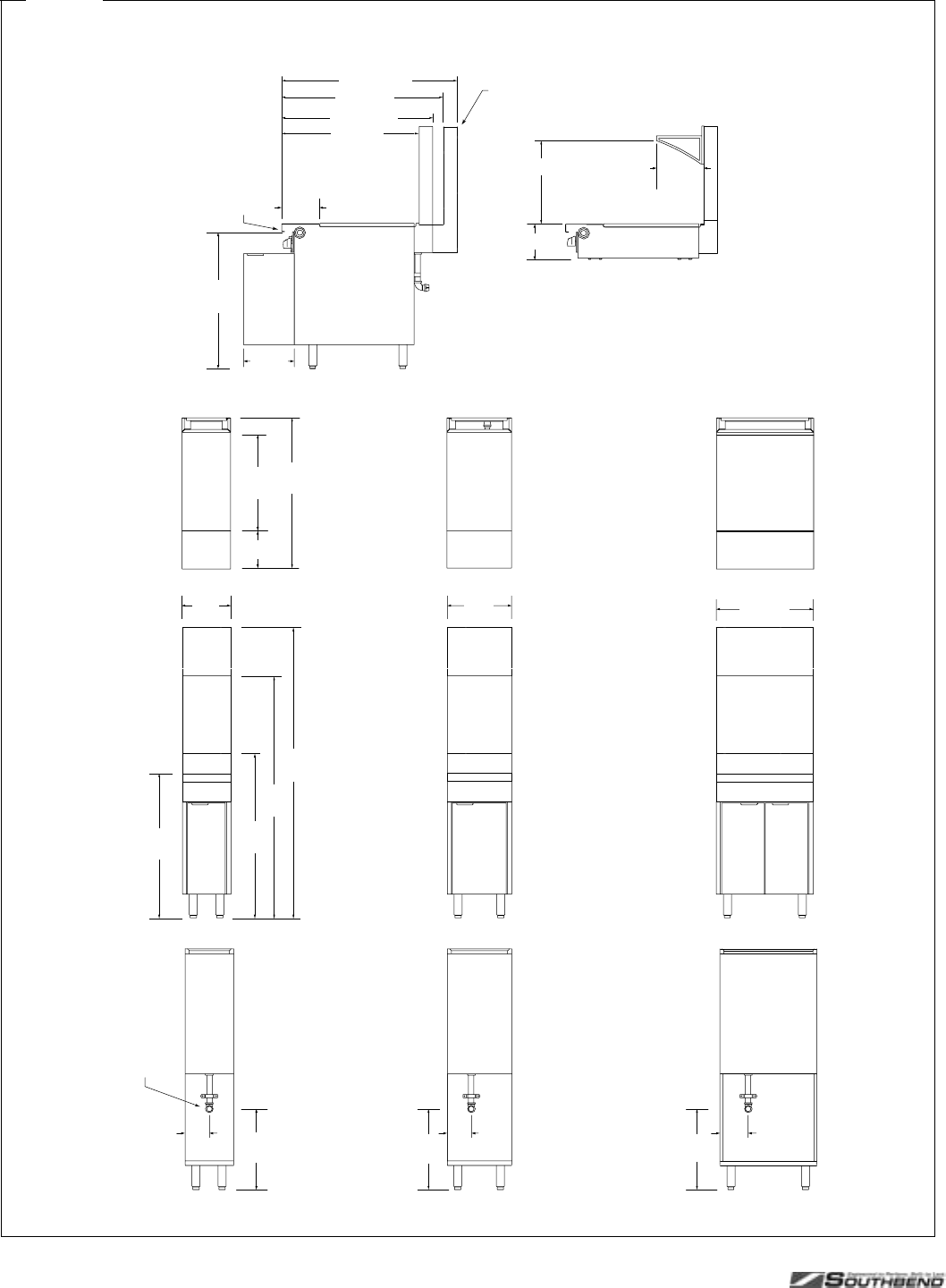
Figure 2
Dimensions
20"
(508)
6"
(152)
37-1/2"
(953)
9-1/4" (235)
24"
(610)
16"
(406)
Optional
Rear Gas
Connection
6" (152) 20"
(508)
60"
(1524)
41"
(1041)
72"
(1829)
5" Flue Riser
24" Flue Riser
36" Flue Riser
12"
(305)
36"
(914)
7" (178)
24" (610)
8-1/2" (216)
SIDE VIEW of Flush-Burner Modular-Base Models
(with 24" flue riser with single shelf)
SIDE VIEW of Flush-Burner 16"-Wide Cabinet-Base Models
37-1/2" (953)
34" (864)
40" (1016)
43-1/2" (1105)
33-3/4"
(859)
9-1/4" (235)
Front Gas
Manifold
12-1/2"
(318)
20-1/2" (521) 11-3/4" (298)
20"
(508)
Flue riser for “deep” depth-option extends rearward 6"
(cooking surface area is same as for “standard” depth).
PLATINUM SERIES SECTIONAL RANGE SPECIFICATIONS
INSTALL AND OPERATIONS MANUAL 1185836 REV 3 (07/06) PAGE 7 OF 80
Figure 3
Dimensions (continued)
SIDE VIEW of Charbroiler/Griddle Modular-Base Models
SIDE VIEW of Optional Equipment Stand
SIDE VIEW of Charbroiler/Griddle Oven-Base Models
1-1/2" (38)
6" (152) 18"
(457)
Electrical
Connection
for Oven
Models
32" (813)
40-1/2"
(1029)
9-1/4" (235)
24"
(610)
20"
(508) 6" (152) 17-1/2"
(445)
48" (1219)
20"
(508)
Optional
Rear Gas
Connection
60"
(1524)
41"
(1041)
72"
(1829)
5" Flue Riser
24" Flue Riser
36" Flue Riser
36"
(914)
2-1/2" (64) 18"
(457)
7" (178)
Electrical
Connection
for Oven
Models

SPECIFICATIONS PLATINUM SERIES SECTIONAL RANGE
PAGE 8 OF 80 INSTALL & OPERATIONS MANUAL 1185836 REV 3 (07/06)
UTILITY REQUIREMENTS AND CRATED WEIGHT
GAS ELECTRICITY
Model Width Base Type Top Type Natural Gas
(BTU/hour) Propane
(BTU/hour) 120V
(amps) 208/240V
(amps)
Crated Weight
pounds (kg)
P12C-B 12" cabinet 2 flush open-burners 66,000 60,000 - - 200 (91)
P12N-B 12" modular 2 flush open-burners 66,000 60,000 - - 130 (59)
P16C-C 16" cabinet charbroiler 40,000 36,000 - - 220 (100)
P16C-G 16" cabinet standard griddle 40,000 36,000 - - 270 (122)
P16C-H 16" cabinet uniform hot top 40,000 36,000 - - 220 (100)
P16C-T 16" cabinet thermostatic griddle 40,000 36,000 - - 270 (122)
P16C-X 16" cabinet 2 flush PyroMax open-burners 90,000 84,000 - - 220 (100)
P16N-C 16" modular charbroiler 40,000 36,000 - - 150 (68)
P16N-G 16" modular standard griddle 40,000 36,000 - - 240 (108)
P16N-H 16" modular uniform hot top 40,000 36,000 - - 150 (68)
P16N-T 16" modular thermostatic griddle 40,000 36,000 - - 240 (108)
P16N-X 16" modular 2 flush PyroMax open-burners 90,000 84,000 - - 150 (68)
P24C-CC 24" cabinet charbroiler 64,000 56,000 - - 360 (163)
P24N-CC 24" modular charbroiler 64,000 56,000 - - 360 (163)
P32A-BBB 32" convection oven 6 flush open-burners 243,000 222,000 4.8 2.6 670 (305)
P32A-BBB-SU 32" convection oven 6 open-burners (rear burners raised) 243,000 222,000 4.8 2.6 670 (305)
P32A-CC 32" convection oven charbroiler 125,000 114,000 4.8 2.6 670 (305)
P32A-GG 32" convection oven standard griddle 125,000 114,000 4.8 2.6 740 (336)
P32A-GRAD 32" convection oven graduated hot-top 107,000 87,000 4.8 2.6 670 (305)
P32A-HH 32" convection oven uniform hot top 125,000 114,000 4.8 2.6 670 (305)
P32A-TT 32" convection oven thermostatic griddle 125,000 114,000 4.8 2.6 740 (336)
P32A-XG 32" convection oven 2 PyroMax open-burners (left side),
standard griddle (right side) 175,000 168,000 4.8 2.6 705 (320)
P32A-XH 32" convection oven 2 PyroMax open-burners (left side),
uniform hot-top (right side) 175,000 168,000 4.8 2.6 670 (305)
P32A-XH-RE 32" convection oven 2 PyroMax open-burners (front),
uniform hot-top (rear) 175,000 168,000 4.8 2.6 670 (305)
P32A-XT 32" convection oven 2 PyroMax open-burners (left side),
thermostatic griddle (right side) 175,000 168,000 4.8 2.6 705 (320)
P32A-XX 32" convection oven 4 PyroMax flush open-burners 225,000 200,000 4.8 2.6 670 (305)
P32C-BBB 32" cabinet 6 flush open-burners 198,000 180,000 - - 450 (205)
P32C-BBB-SU 32" cabinet 6 open-burners (rear burners raised) 198,000 180,000 - - 450 (205)
P32C-CC 32" cabinet charbroiler 80,000 72,000 - - 450 (205)
P32C-GG 32" cabinet standard griddle 80,000 72,000 - - 560 (255)
P32C-GRAD 32" cabinet graduated hot-top 62,000 45,000 - - 490 (223)
P32C-HH 32" cabinet uniform hot top 80,000 72,000 - - 490 (223)
P32C-TT 32" cabinet thermostatic griddle 80,000 72,000 - - 560 (255)
P32C-XG 32" cabinet 2 PyroMax open-burners (left side),
standard griddle (right side) 130,000 126,000 - - 525 (238)
P32C-XH 32" cabinet 2 PyroMax open-burners (left side),
uniform hot-top (right side) 130,000 126,000 - - 490 (223)
P32C-XH-RE 32" cabinet 2 PyroMax open-burners (front),
uniform hot-top (rear) 124,000 120,000 - - 490 (223)
P32C-XT 32" cabinet 2 PyroMax open-burners (left side),
thermostatic griddle (right side) 130,000 126,000 - - 525 (238)
P32C-XX 32" cabinet 4 PyroMax flush open-burners 180,000 168,000 - - 490 (223)
P32D-BBB 32" standard oven 6 flush open-burners 243,000 222,000 1.0 1.0 530 (241)
P32D-BBB-SU 32" standard oven 6 open-burners (rear burners raised) 243,000 222,000 1.0 1.0 530 (241)
P32D-CC 32" standard oven charbroiler 125,000 114,000 1.0 1.0 530 (241)
P32D-GG 32" standard oven standard griddle 125,000 114,000 1.0 1.0 700 (318)
P32D-GRAD 32" standard oven graduated hot-top 107,000 87,000 1.0 1.0 630 (286)
P32D-HH 32" standard oven uniform hot top 125,000 114,000 1.0 1.0 630 (286)
P32D-TT 32" standard oven thermostatic griddle 125,000 114,000 1.0 1.0 700 (318)
P32D-XG 32" standard oven 2 PyroMax open-burners (left side),
standard griddle (right side) 175,000 168,000 1.0 1.0 665 (302)
P32D-XH 32" standard oven 2 PyroMax open-burners (left side),
uniform hot-top (right side) 175,000 168,000 1.0 1.0 630 (286)
P32D-XH-RE 32" standard oven 2 PyroMax open-burners (front),
uniform hot-top (rear) 169,000 165,000 1.0 1.0 630 (286)
table continues on next page

PLATINUM SERIES SECTIONAL RANGE SPECIFICATIONS
INSTALL AND OPERATIONS MANUAL 1185836 REV 3 (07/06) PAGE 9 OF 80
GAS ELECTRICITY
Model Width Base Type Top Type Natural Gas
(BTU/hour) Propane
(BTU/hour) 120V
(amps) 208/240V
(amps)
Crated Weight
pounds (kg)
P32D-XT 32" standard oven 2 PyroMax open-burners (left side),
thermostatic griddle (right side) 175,000 168,000 1.0 1.0 665 (302)
P32D-XX 32" standard oven 4 PyroMax flush open-burners 225,000 200,000 1.0 1.0 630 (286)
P32N-BBB 32" modular 6 flush open-burners 198,000 180,000 - - 260 (118)
P32N-BBB-SU 32" modular 6 open-burners (rear burners raised) 198,000 180,000 - - 260 (118)
P32N-CC 32" modular charbroiler 80,000 72,000 - - 260 (118)
P32N-GG 32" modular standard griddle 80,000 72,000 - - 400 (182)
P32N-GRAD 32" modular graduated hot-top 62,000 45,000 - - 315 (143)
P32N-HH 32" modular uniform hot top 80,000 72,000 - - 315 (143)
P32N-TT 32" modular thermostatic griddle 80,000 72,000 - - 400 (182)
P32N-XG 32" modular 2 PyroMax open-burners (left side),
standard griddle (right side) 130,000 126,000 - - 358 (162)
P32N-XH 32" modular 2 PyroMax open-burners (left side),
uniform hot-top (right side) 130,000 126,000 - - 315 (143)
P32N-XH-RE 32" modular 2 PyroMax open-burners (front),
uniform hot-top (rear) 124,000 120,000 - - 315 (143)
P32N-XT 32" modular 2 PyroMax open-burners (left side),
thermostatic griddle (right side) 130,000 126,000 - - 358 (162)
P32N-XX 32" modular 4 PyroMax flush open-burners 180,000 168,000 - - 315 (143)
P36A-CCC 36" convection oven charbroiler 173,000 154,000 4.8 2.6 621 (281)
P36C-CCC 36" cabinet charbroiler 128,000 112,000 - - 462 (209)
P36D-CCC 36" standard oven charbroiler 173,000 154,000 1.0 1.0 568 (257)
P36N-CCC 36" modular charbroiler 128,000 112,000 - - 276 (125)
P36W-CCC 36” modular wood smoker 96,000 84,000 - - 330(150)
P48A-BBBB 48" convection oven
and cabinet 8 flush open burners 309,000 282,000 4.8 2.6 621 (281)
P48A-CCCC 48" convection oven
and cabinet charbroiler 165,000 150,000 4.8 2.6 621 (281)
P48A-GGG 48" convection oven
and cabinet standard griddle 165,000 150,000 4.8 2.6 840 (378)

OPERATION PLATINUM SERIES SECTIONAL RANGE
PAGE 10 OF 80 INSTALL & OPERATIONS MANUAL 1185836 REV 3 (07/06)
OPERATION
DANGER
EXPLOSION HAZARD
In the event a gas odor is detected, shut down equipment at the main shut off valve. Immediately call the
emergency phone number of your gas supplier.
CAUTION
If a pilot flame pilot should go out, the flow of gas to the corresponding burner is NOT interrupted. Consequently, it
is the responsibility of the operator to check the ignition of each burner immediately EVERY TIME a burner is
turned on. Should ignition fail after 10 seconds, turn off the burner, wait 5 minutes, and then try again.
LIGHTING AFTER GAS HAS BEEN SHUT OFF
When turning on the main gas supply to a sectional range, do the following:
1. Make sure that all the control knobs and power switches of all the connected appliances are in the OFF position.
2. Turn on the gas-supply shut-off valve(s).
3. Light the standing pilots of each connected appliance.
4. Turn on the ovens of the sectional range first, then wait six minutes before turning on the top sections. This
enables all air to be purged from the sectional-range gas piping.
SHUTDOWN OF ENTIRE RANGE
To place the range in a standby state (ready for use), turn all burner control knobs to OFF, set all thermostats to their
lowest position, and switch all ovens OFF. The pilots will remain lit.
To completely shut down the range for an extended period (or prior to disconnecting the gas supply), place the range
in a standby state (as described in the previous paragraph), then turn OFF the manual shut-off valves of all gas
supply connections. This will extinguish the pilots.
PLATINUM SERIES SECTIONAL RANGE OPERATION
INSTALL AND OPERATIONS MANUAL 1185836 REV 3 (07/06) PAGE 11 OF 80
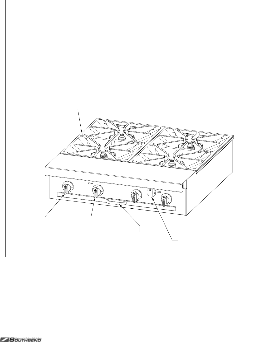
Figure 4
Operation of Open-Burner Sections
Each 12"-wide or 16"-wide section has two control knobs.
The left knob controls the rear burner, while the right knob
controls the front burner. Each knob can be turned to OFF or
to any position in the range from LOW to HIGH.
To start cooking, turn the appropriate control knob to HIGH.
Visually check that the burner ignites. The gas does NOT
automatically shut off if the burner does not ignite! If the
burner does not ignite, check and/or light the pilots (see
procedure at right). When the burner is hot, the burner flame
should appear blue and steady (some slight yellowing of the
flame tips may occur when using propane gas).
While cooking, do not allow excessive drippings and/or
debris to accumulate on or below the burners. When
necessary, pull out and clean the drippings tray.
When done cooking, turn the appropriate control knob to
OFF. (The pilot should remain lit).
Each burner has a pilot located beside the burner. To light a
pilot, do the following:
1. Check that the burner control knob is in the OFF position.
2. Check that the pilot is in the correct position beside the
burner.
3. Turn on the gas supply to the sectional range (if not
already on).
4. Light the pilot with a match or a pilot-lighting device. The
pilot flame should be blue and steady.
Burner Grate
(lifts out for cleaning)
Front-Burner
Control Knob
(OFF, HIGH-to-LOW) Drippings Tray
(slides out for cleaning)
Base-Oven Gas
Shut-Off Valve
(has no effect on
range-top burners)
Rear-Burner
Control Knob
(OFF, HIGH-to-LOW)
OPERATION PLATINUM SERIES SECTIONAL RANGE
PAGE 12 OF 80 INSTALL & OPERATIONS MANUAL 1185836 REV 3 (07/06)
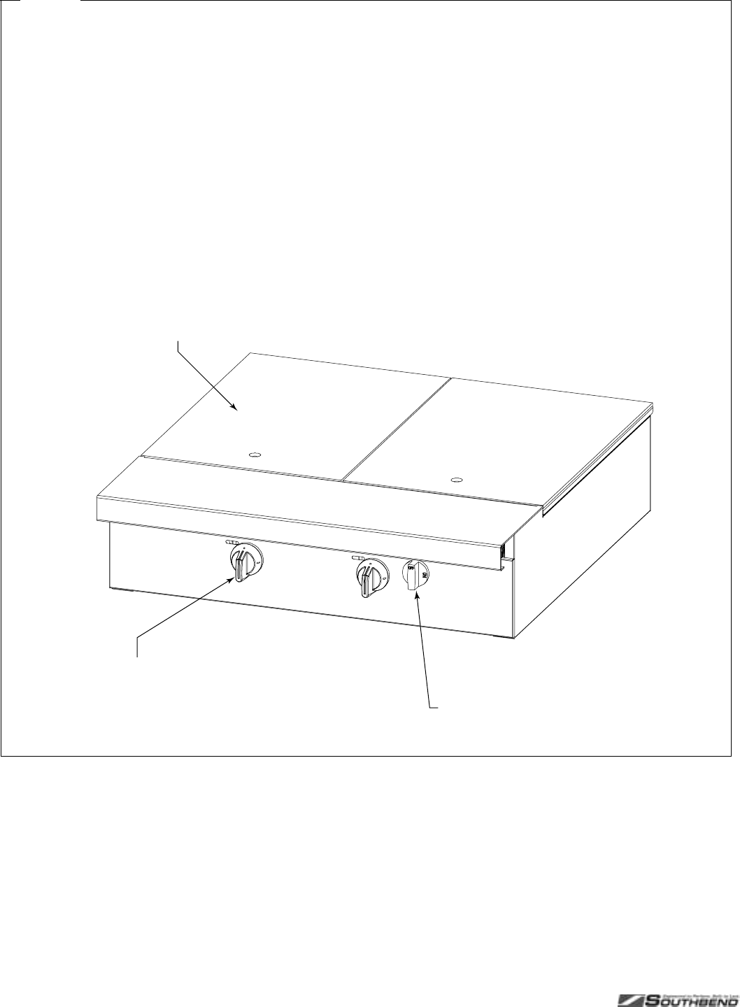
Figure 5
Operation of Uniform Hot-Top Section
Each 16"-wide section has one control knob, which can be
turned to OFF or to any position in the range from LOW to
HIGH. When the control is set to HIGH, the hot top surface
will heat to about 700°F (370°C).
To start cooking, turn the appropriate control knob to HIGH.
Visually check that the burner ignites. The gas does NOT
automatically shut off if the burner does not ignite! If the
burner does not ignite, check and/or light the pilots (see
procedure at right). When the burner is hot, the burner flame
should appear blue and steady (some slight yellowing of the
flame tips may occur when using propane gas).
Do not waste gas and abuse equipment by leaving the
burner on HIGH all the time. During idling periods, turn the
control to LOW to keep the top warm.
When done cooking, turn the appropriate control knob to
OFF. (The pilot should remain lit).
Each 16"-wide section has two burners, each of which has a
pilot located near the front of the burner. To light the pilots,
do the following:
1. Check that the control knob is in the OFF position.
2. Lift up a hot-top section plate in order to expose the two
pilots.
3. Check that each pilot is in the correct position.
4. Turn on the gas supply to the sectional range (if not
already on).
5. Light the pilots with a match or a pilot-lighting device. The
pilot flames should be blue and steady.
Base-Oven Gas
Shut-Off Valve
(has no effect
on hot-top)
Burner Control Knob
(OFF, HIGH-to-LOW)
Uniform Hot Top Plat
e
(lifts out for cleaning
and lighting pilot)
PLATINUM SERIES SECTIONAL RANGE OPERATION
INSTALL AND OPERATIONS MANUAL 1185836 REV 3 (07/06) PAGE 13 OF 80
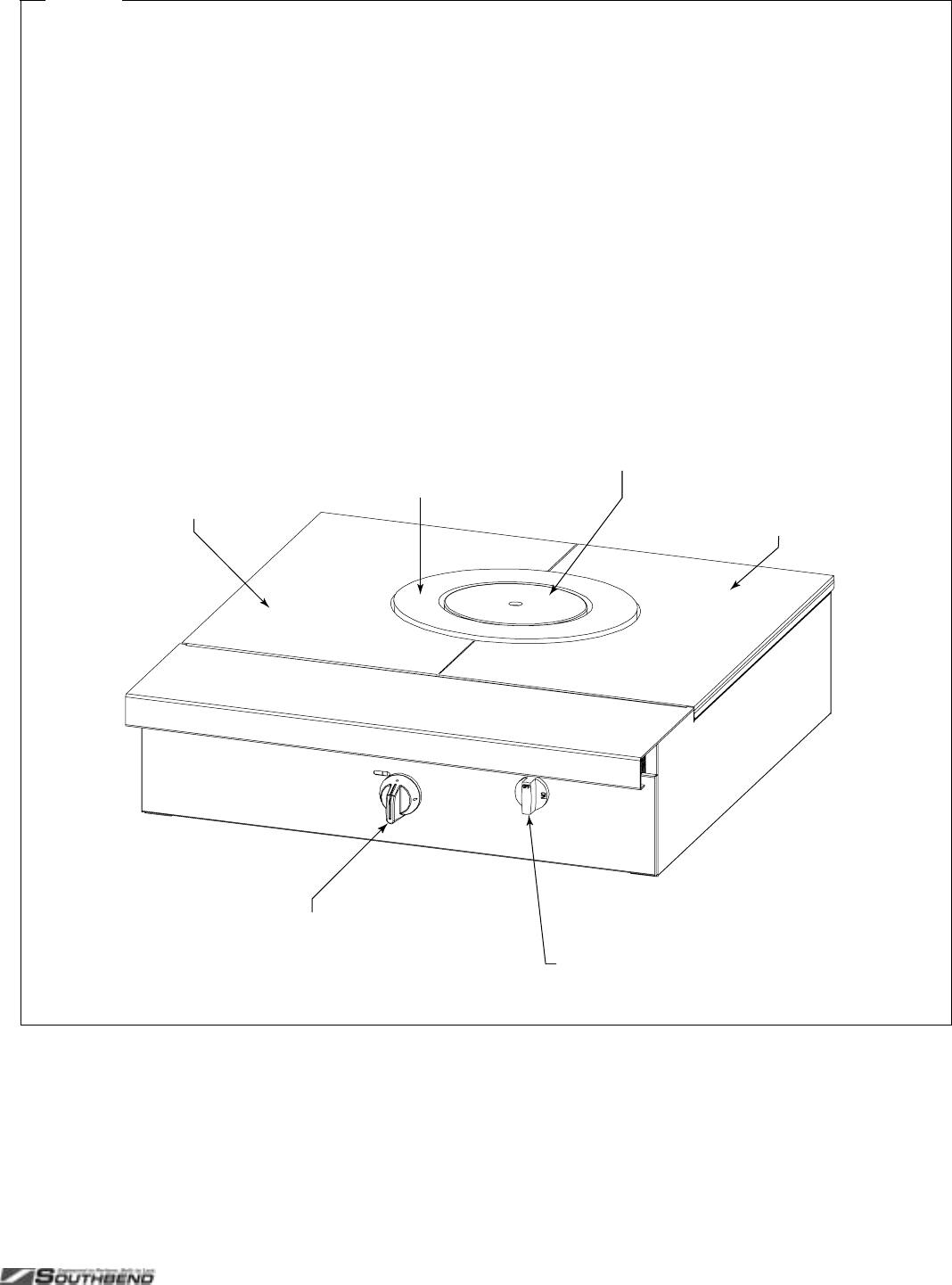
Figure 6
Operation of Graduated Hot-Top Section
Each 32"-wide section has one control knob, which can be
turned to OFF or to any position in the range from LOW to
HIGH. When the control is set to HIGH, the round center
section will heat to about 725°F (385°C), the ring-shaped
section will heat to about 625°F (330°C), and the outer areas
will heat to about 500°F (260°C).
To start cooking, turn the control knob to HIGH. Visually
check that the burner ignites. The gas does NOT
automatically shut off if the burner does not ignite! If the
burner does not ignite, check and/or light the pilots (see
procedure at right). When the burner is hot, the burner flame
should appear blue and steady (some slight yellowing of the
flame tips may occur when using propane gas).
Do not waste gas and abuse equipment by leaving the
control on HIGH all the time. During idling periods, turn the
control to LOW to keep the top warm.
When done cooking, turn the control knob to OFF. (The pilot
should remain lit).
Each 32"-wide section has one burner. The pilot is located
adjacent to the burner. To light the pilot, do the following:
1. Check that the control knob is in the OFF position.
2. Lift out the round center plate in order to expose the pilot.
3. Check that the pilot is in the correct position.
4. Turn on the gas supply to the sectional range (if not
already on).
5. Light the pilot with a match or a pilot-lighting device. The
pilot flame should be blue and steady.
Burner Control Knob
(OFF, HIGH-to-LOW) Base-Oven Gas
Shut-Off Valve
(has no effect
on hot-top)
Lower Temperature Area
(plate lifts out for cleaning
)
Medium Temperature Area
(plate lifts out for cleaning)
HighTemperature Are
a
(plate lifts out for cleaning
and lighting pilot)
Lower Temperature Area
(plate lifts out for cleaning)
OPERATION PLATINUM SERIES SECTIONAL RANGE
PAGE 14 OF 80 INSTALL & OPERATIONS MANUAL 1185836 REV 3 (07/06)
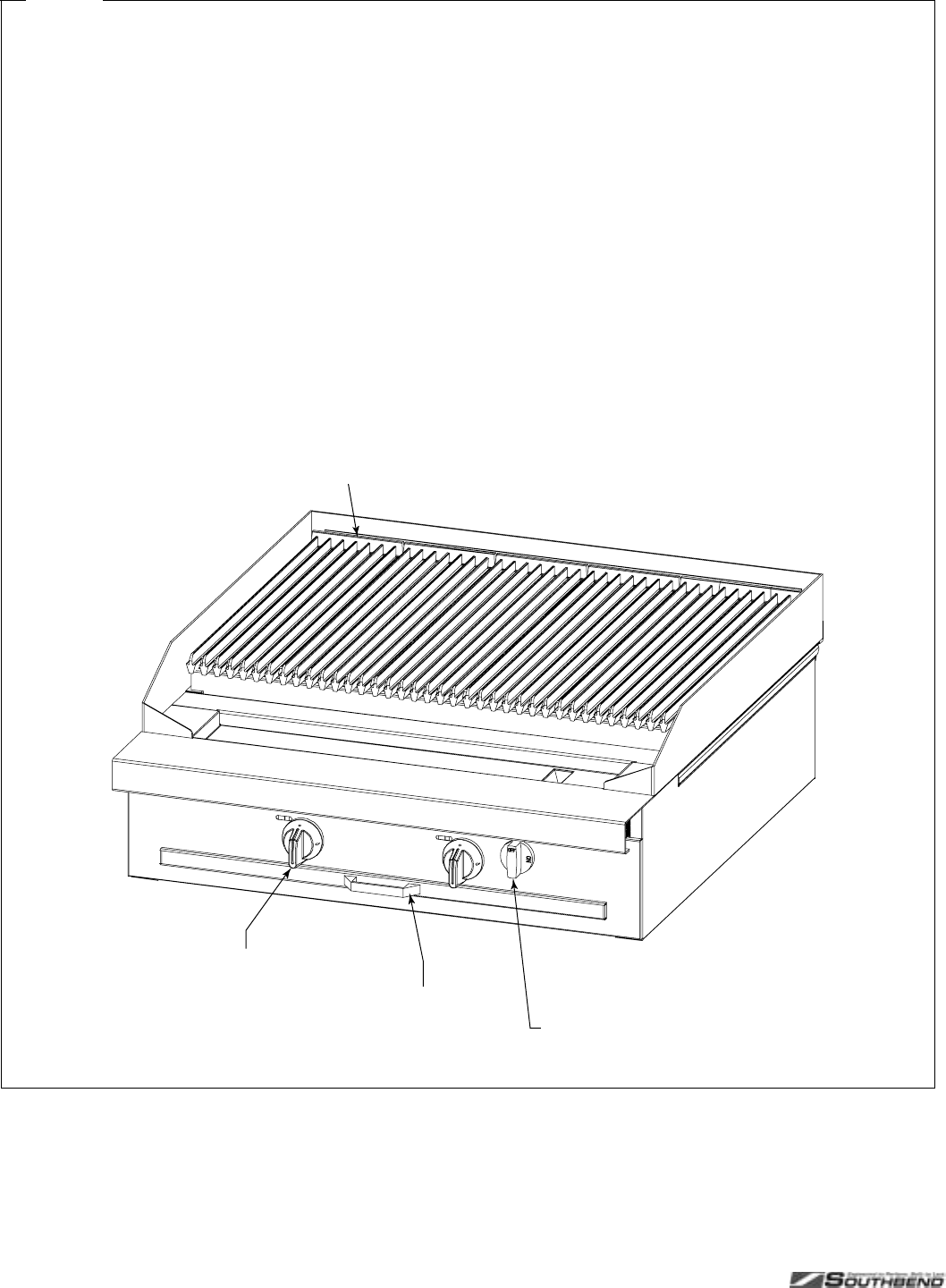
Figure 7
Operation of Charbroiler Section
Each 12"-wide or 16"-wide section has one control knob,
which can be turned to OFF, HIGH, or LOW. Each 6"-wide
burner top-grate can be turned over to provide either wide
branding marks or narrower branding marks with channels to
carry away drippings (and so reduce flare up). The back-to-
front slope of each top-grate is adjusted by positioning the
back end of the top-grate on either the lower or the higher
grate-support rail. The radiants (just above the burners) can
be reversed front-and-back to provide higher heat toward the
back than the front, or vice versa. “Lava rock” briquettes can
be placed on grates located above the radiants.
To start cooking, turn the appropriate control knob to HIGH.
Visually check that the burner ignites. The gas does NOT
automatically shut off if the burner does not ignite! If the
burner does not ignite, check and/or light the pilots (see
procedure at right). When the burner is hot, the burner flame
should appear blue and steady (some slight yellowing of the
flame tips may occur when using propane gas).
When done cooking, turn the appropriate control knob to
OFF. (The pilot should remain lit).
Each 12"-wide or 16"-wide section has two burners, each of
which has a pilot located near the front of the burner. To light
the pilots, do the following:
1. Check that the burner control knob is in the OFF position.
2. Lift up a grate in order to expose the two pilots. They are
accessible through a slot near the front end of the radiant
plate.
3. Check that each pilot is in the correct position.
4. Turn on the gas supply to the sectional range (if not
already on).
5. Light the pilots with a match or a pilot-lighting device. The
pilot flames should be blue and steady.
Grates
(lift out for cleaning)
Burner Control Knob
(OFF, HIGH, or LOW) Drippings Tray
(slides out for cleaning)
Base-Oven Gas
Shut-Off Valve
(has no effect
on charbroiler)
PLATINUM SERIES SECTIONAL RANGE OPERATION
INSTALL AND OPERATIONS MANUAL 1185836 REV 3 (07/06) PAGE 15 OF 80
Figure 8
Operation of Wood Smoker Section
Wood Type(s): Split or Chunk Wood.
Wood Chunks:
Hickory Chunks, 10 lb bag, Southbend P/N 1188495
Mesquite Chunks, 10 lb bag Southbend P/N 1188496
Split Wood:
4” diameter X 20” long or smaller
Operation:
a.) Fill WATER/CATCH tray with water to bottom of wood
grate.
b.) Place even layer of selected wood on wood grate inside
smoker box.
c.) Turn control knobs to high position. Wood will then self
ignite.
(Ignition time for wood in smoker will vary due to
moisture content and type of wood used)
d.) Wood life can be extended by pre-soaking wood in
water for a couple of hours prior to use.
e.) It is not recommended to soak wood overnight. Wood
will become too saturated and delay ignition.
f.) Smoker box door should remain closed during normal
operation.
Shutdown:
a.) Extinguish all remaining embers, or allow all wood to
burnout.
b.) Place all remaining wood in a fire-safe container.
c.) Remove wood grate for cleaning.
d.) Remove Water/Catch tray and dispose of content in a
fire-safe container.
WARNING / CAUTION
a.) Never use treated wood. When burned, treated wood
can release pollutants harmful to your health into the air.
OPERATION PLATINUM SERIES SECTIONAL RANGE
PAGE 16 OF 80 INSTALL & OPERATIONS MANUAL 1185836 REV 3 (07/06)
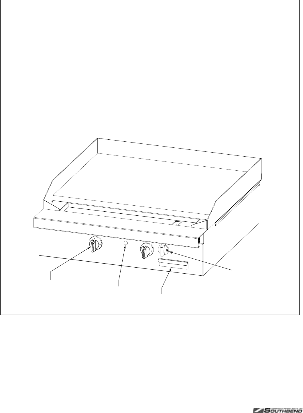
Figure 9
Operation of Standard (Non-Thermostatic) Griddle Sections
Each 16"-wide section has one control knob, which can be
turned to OFF, HIGH, or LOW.
To start cooking, turn the appropriate control knob to HIGH.
Check that the burner ignites. The gas does NOT
automatically shut off if the burner does not ignite! If the
burner does not ignite, check and/or light the pilots (see
procedure at right). When the burner is hot, the burner flame
should appear blue and steady (some slight yellowing of the
flame tips may occur when using propane gas).
Always remember to heat the griddle slowly because quick
heating may cause costly damage. Never place utensils on
the griddle.
Do not waste gas and abuse equipment by leaving the
controls on HIGH all the time. During idling periods, turn the
control to LOW to keep the griddle warm. (Do not allow the
griddle to overheat above 550°F (288°C), as this will cause
warping or breakage.)
When necessary while cooking, pull out and empty the
grease drawer.
When done cooking, turn the appropriate control knob to
OFF. (The pilot should remain lit).
Each 16" or 32" griddle section has a single pilot that is lit
using a long match inserted thorough a hole in the front
valve panel. (A 48"-wide griddle has two pilots.) To light the
pilot, do the following:
1. Check that all the control knobs are in the OFF position.
2. Turn on the gas supply to the sectional range (if not
already on).
3. Light the pilot by inserting a long match (at least 11" long)
or pilot-lighting device straight into the hole on the front
valve panel of the griddle.
Pilot-Lighting
Opening
Burner Control Knob
(OFF, HIGH, or LOW) Grease Drawer
(slides out for cleaning)
Base-Oven Gas
Shut-Off Valve
(has no effect
on griddle)
PLATINUM SERIES SECTIONAL RANGE OPERATION
INSTALL AND OPERATIONS MANUAL 1185836 REV 3 (07/06) PAGE 17 OF 80
Fi
g
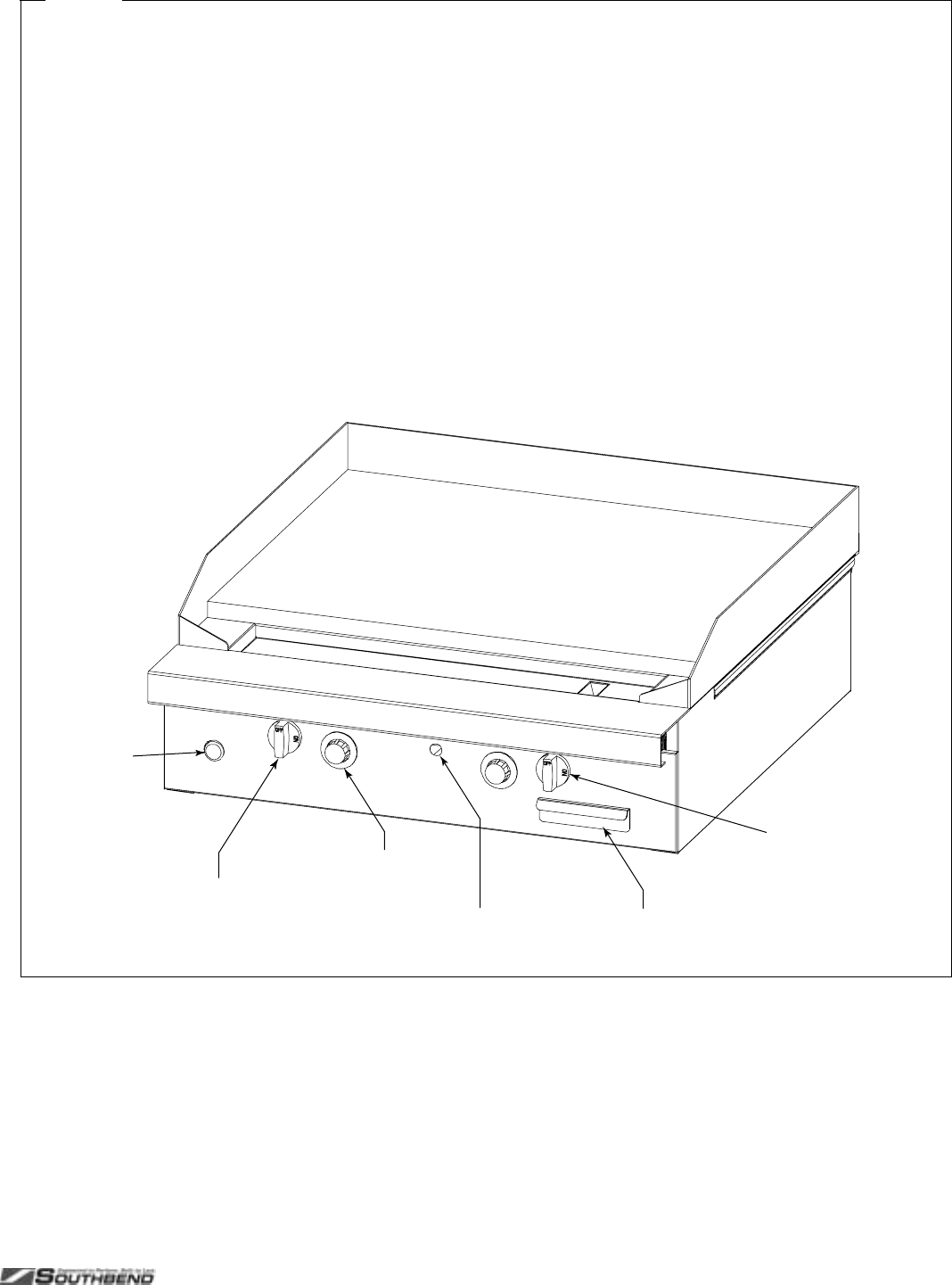
ure 10
Operation of Thermostatic Griddle Sections
Each 16"-wide section has one control knob that can be
turned to OFF, or to any temperature in the range 150°F to
400°F (66°C to 204°C).
To start cooking, turn on the appropriate control knob. Check
that the burner ignites. If the burner does not ignite, check
and/or light the pilots (see procedure at right).
Never place utensils on the griddle.
Do not waste gas and abuse equipment by leaving the
thermostat at a high temperature all the time. During idling
periods, turn the thermostat to a low temperature to keep the
griddle warm. (Do not allow the griddle to overheat above
550°F (288°C), as this will cause warping or breakage.)
When necessary while cooking, pull out and empty the
grease drawer.
When done cooking, turn the appropriate control knob to
OFF. (The pilot should remain lit).
Each 16" or 32" griddle section has a single pilot that is lit
using a long match inserted thorough a hole in the front
valve panel. (A 48"-wide griddle has two pilots.) To light the
pilot, do the following:
1. Check that all control knobs are in the OFF position.
2. Turn on the gas supply to the sectional range (if not
already on).
3. Turn on the Griddle Gas Shut-Off Valve (if not already
on).
4. Press and hold in the Safety Switch Button.
5. Light the pilot by inserting a long match (at least 11" long)
or pilot-lighting device straight into the hole on the front
valve panel of the griddle.
6. After about a minute, release the Safety Switch Button.
The pilot should remain lit.
Pilot-Lighting
Opening
Burner Control Knob
(OFF, temperature)
Grease Drawer
(slides out for cleaning)
Griddle Gas
Shut-Off Valve
Safety
Switch
Button
Base-Oven Gas
Shut-Off Valve
(has no effect
on griddle)
OPERATION PLATINUM SERIES SECTIONAL RANGE
PAGE 18 OF 80 INSTALL & OPERATIONS MANUAL 1185836 REV 3 (07/06)
Fi
g
ure 11
Operation of Oven
Each oven has a thermostatic control that can be set in the
range 150°F to 500°F (66°C to 260°C). Convection ovens
have a fan that can be set to either HI speed or LO speed.
For advice on using a convection oven, see the information
on the following two pages of this manual.
To start cooking, do the following:
1. Turn the Oven Gas Shut-Off Valve to ON.
2. Set the Oven Power Switch to ON. The Cooking Light will
come on, and the pilot will light automatically. (You will
hear a “snapping” sound until the pilot ignites.)
3. For convection ovens, select the fan speed appropriate
for the food to be cooked.
4. Select the cooking temperature appropriate for the food
to be cooked.
5. When the oven reaches the set temperature, the Cooking
Light will go out.
While cooking, if the door is opened on a convection oven,
the fan and heat will temporarily stop until the door is closed.
Do not allow excessive drippings and/or debris to
accumulate on the interior of the oven. When necessary, pull
out and clean the oven-bottom tray.
When done cooking, turn the Oven Power Switch to OFF
and turn the Oven Gas Shut-Off Valve to OFF.

PLATINUM SERIES SECTIONAL RANGE OPERATION
INSTALL AND OPERATIONS MANUAL 1185836 REV 3 (07/06) PAGE 19 OF 80
SUGGESTIONS FOR COOKING USING A CONVECTION OVEN
As a guide, set oven temperatures 25 to 50 degrees lower than called for in recipes using conventional (non-
convection) ovens.
FROZEN ENTREE PRODUCTS: Punch holes in lid before heating. Tent lid if product has a tendency to stick, i.e.,
lasagna or macaroni and cheese. Use manufacturer’s convection oven directions for time and temperature or reduce
conventional oven temperature 50 degrees for a 6-1/2 size pan load. Some products may cook in 10 to 15 minutes
less time than recommended for convection ovens if prepared from frozen in a 6 pan load.
Time and temperatures will vary depending upon load, mix, size of portion, and other factors. Use the following chart
to develop your own cooking techniques:
Product Timing
(minutes) Temperature
Setting Number of
Racks Used Count per
Pan/Rack
Hamburger buns, 3 oz. - 4" 18 375° 3 24
Yeast rolls - 1 oz.
Use temperature and time recommended by
manufacturer for convection ovens for a 3 pan load.
10 400° 3 48
Fruit pies, 46 oz. frozen
Use temperature and time from manufacturer’s directions
for convection ovens for a 12 pie load placed on 3 bun
pans.
50 375° 3 4
Egg custard pies, 44 oz. frozen 60 325° 3 4
Dutch apple pies, 46 oz. frozen 50 350° 3 4
Baked potatoes, 8 oz.
Wash and wrap in potato foil. Place 30 potatoes on 18 x
24 bun pan — 3 pans per load. Bake in 400°F oven for 1
hour.
60 400° 3 30 (wrapped)
Pre-blanched potatoes, frozen
Spread on ungreased bun pans, 3 pans per load. Bake
at 400°F, stirring once, for 15 to 18 minutes.
16 400° 3 5 lb.
Fish portions, pre-cooked, breaded, 3 oz.
Use manufacturer’s recommended temperature and time
for convection oven for a 3 pan load.
16 400° 3 32
Macaroni & cheese, 6 lbs. - 40° temp. 45 400° 3 2-6 lbs.
Lasagna w/meat sauce, 6 lb. - 40° temp. 60 350° 3 2 - 6 lbs.
Lasagna w/meat sauce, 6 lb. - frozen 75 350° 3 2-6 lbs.
Salisbury steak w/gravy, 6 lb. - 40° temp. 45 400° 3 2-6 lbs.
Top round of beef No. 168
14 lb. - rare 140° internal
14 min./lb. 250° 1 1 - 2
14 lb. - medium 150° internal
14 min./lb. 250° 1 1 - 2
14 lb. - well done 160° internal
14 min./lb. 250° 1 1 - 2

OPERATION PLATINUM SERIES SECTIONAL RANGE
PAGE 20 OF 80 INSTALL & OPERATIONS MANUAL 1185836 REV 3 (07/06)
CORRECTING PROBLEMS WHEN COOKING WITH A CONVECTION OVEN
If… then…
Cakes are dark on the sides and not done in the center… lower oven temperature.
Cake edges are too brown… reduce number of pans or lower oven temperature.
Cakes have light outer color… raise temperature.
Cake settles slightly in the center… bake longer or raise oven temperature slightly. Do not open
doors too often for long periods.
Pies have uneven color… reduce number of pies per rack.
Meats are browned, but not done in center… lower oven temperature and roast longer.
Meats are well done and not browned… raise temperature. Limit amount of moisture.
Cakes ripple… pans are overloaded or batter is too thin.
There is excessive meat shrinkage… lower oven temperature.
Cakes are too coarse… lower oven temperature.

PLATINUM SERIES SECTIONAL RANGE CLEANING & MAINTENANCE
INSTALL AND OPERATIONS MANUAL 1185836 REV 3 (07/06) PAGE 21 OF 80

CLEANING & MAINTENANCE PLATINUM SERIES SECTIONAL RANGE
PAGE 22 OF 80 INSTALL & OPERATIONS MANUAL 1185836 REV 3 (07/06)
CLEANING & MAINTENANCE
WARNING
Shut off the gas supply to the appliance before cleaning or performing maintenance on any gas appliance.
The appliance may be equipped with a restraint device to limit its movement in order to prevent damage to the
gas connection. If disconnection of this restraint is necessary to move the appliance for cleaning or
maintenance, reconnect the restraint when the appliance is moved back to its original installed position.
Southbend appliances are sturdily constructed of the best materials and are designed to provide durable service when
treated with ordinary care. To expect the best performance, your equipment must be maintained in good condition and
cleaned daily. Naturally, the periods for this care and cleaning depend on the amount and degree of usage.
Following daily and periodic maintenance procedures will enhance long life for your equipment. Climatic conditions
(such as salt air) may require more thorough and frequent cleaning or the life of the equipment could be adversely
affected.
Keep exposed, cleanable areas clean at all times.
DAILY CLEANING AND MAINTENANCE
The daily cleaning procedure is as follows:
1. Shut off the main gas supply and allow the sectional range to cool.
2. Pull out, empty, and clean all drippings trays and grease drawers.
3. Remove and clean all oven racks and oven-bottom trays. Wipe clean the interior of the oven.
4. Visually check for any food and/or debris that may have fallen down into the burner areas.
5. Wipe clean all exterior surfaces.
6. Replace the cleaned and dried drippings trays, grease drawers, and oven components.
7. Check that nothing has been left on or near the sectional range that might block the entry of combustion air or
the escape of combustion exhaust.
MONTHLY CLEANING AND MAINTENANCE
The following tasks should be performed monthly:
1. Clean around burner air mixers and orifices if lint has accumulated in these areas.
2. Check for proper pilot operation. Check that the pilot flames are blue (with little or no yellow in the flame tips),
stable (not lifting off the pilots), and not producing carbon. If adjustment is necessary, call for service.
3. Check for proper burner operation. The burner flames should be blue and stable. If adjustment is necessary, call
for service.
SEMIANNUAL CLEANING AND MAINTENANCE
At least twice a year the venting system should be examined and cleaned.
STAINLESS-STEEL SURFACES
To remove normal dirt, grease and product residue from stainless steel surfaces that operate at LOW temperature,
use ordinary soap and water (with or without detergent) applied with a sponge or cloth. Dry thoroughly with a clean
cloth.
To remove BAKED-ON grease and food splatter, or condensed vapors; apply cleanser to a damp cloth or sponge and
rub cleanser on the metal in the direction of the polishing lines on the metal. Rubbing cleanser, as gently as possible,
in the direction of the polished lines will not mar the finish of the stainless steel. NEVER RUB WITH A CIRCULAR
MOTION. Soil and burnt deposits which do not respond to the above procedure can usually be removed by rubbing
the surface with SCOTCH-BRITE scouring pads or STAINLESS scouring pads. DO NOT USE ORDINARY STEEL

PLATINUM SERIES SECTIONAL RANGE CLEANING & MAINTENANCE
INSTALL AND OPERATIONS MANUAL 1185836 REV 3 (07/06) PAGE 23 OF 80
WOOL as any particles left on the surface will rust and further spoil the appearance of the finish. NEVER USE A
WIRE BRUSH, STEEL SCOURING PADS (EXCEPT STAINLESS), SCRAPER, FILE OR OTHER STEEL TOOLS.
Surfaces which are marred collect dirt more rapidly and become more difficult to clean. Marring also increases the
possibility of corrosive attack. Refinishing may then be required.
“Heat tint” is darkened areas that sometimes appear on stainless steel surfaces where the area has been subjected to
excessive heat. These darkened areas are caused by thickening of the protective surface of the stainless steel and
are not harmful. Heat tint can normally be removed by the foregoing, but tint which does not respond to this procedure
calls for a vigorous scouring in the direction of the polish lines using SCOTCH-BRITE scouring pads or a STAINLESS
scouring pad in combination with a powered cleanser. Heat tint may be lessened by reducing heat to equipment
during slack periods.
BLACK BAKED-ENAMEL SURFACES
Allow appliance to cool somewhat after use and wash black baked-enamel surfaces with a hot, mild detergent or soap
solution. In particular, clean off all grease deposits. Dry thoroughly with a dry cloth.
OPEN-BURNERS AND GRATES
The grates can be removed and cleaned with a solution of hot water and strong soap or detergent. The burners
themselves require little attention, but if spillage should occur, it may be necessary to clean around pilot areas, air
mixer and under burners. Use a wire brush if necessary. Periodically, open-burners should be removed and cleaned.
Allow the interior of the burner to drain, and dry thoroughly before replacing.
HOT-TOP SURFACES
Before cleaning hot-top surfaces, allow them to cool. If water is used on hot-tops while they are still hot, they may
crack, so avoid this practice. The hot-top plates can be removed and cleaned with hot water and detergent. A wire
brush may be used on the underside of the hot top plate. It is recommended not to clean tops while still on the range,
even if cooled, as excess water will drip into the burner box and deteriorate the metal.
CARE OF GRIDDLES
A griddle should be carefully cared for in order to avoid possible damage. (The griddle should have been tempered as
part of the installation procedure, see page 31). Use a Norton Alundum Griddle Brick to clean the griddle. Do not use
any type of steel wool. Small particles may be left on the surface and get into food products. Do not clean spatula by
hitting the edge on the griddle plate. Such action will only cut and pit the griddle plate, leaving it rough and hard to
clean.
OVEN INTERIOR
WARNING
FOR YOUR SAFETY, DISCONNECT THE POWER SUPPLY TO THE SECTIONAL RANGE BEFORE
CLEANING THE OVEN. WHEN CLEANING THE BLOWER WHEEL OF A CONVECTION OVEN, BE SURE TO
HAVE THE POWER SWITCH IN THE “OFF” POSITION.
To clean the oven interior, first allow the oven to cool. Remove oven bottom and clean it by rubbing with strong
detergent and a Brillo pad or similar scrubber. “Spillovers” should be cleaned from the bottom as soon as possible to
prevent carbonizing and a “burnt-on” condition. For stubborn accumulations, commercial oven cleaners are
recommended.
The porcelain oven door lining can be cleaned in a similar manner. The side, rear and top lining should be wiped only
with a cloth dampened with a mild detergent and water. Avoid using excessive amounts of water, as this may drip into
burner compartment and deteriorate the metal in that area. Do not use strong commercial cleaners or abrasive pads
on the side, rear or top linings, as they may damage the finish or leave gray residue.

INSTALLATION PLATINUM SERIES SECTIONAL RANGE
PAGE 24 OF 80 INSTALL & OPERATIONS MANUAL 1185836 REV 3 (07/06)
INSTALLATION
NOTICE
These installation procedures must be followed by qualified personnel or warranty will be void.
Local codes regarding installation vary greatly from one area to another. The National Fire Protection Association,
Inc., states in its NFPA 96 latest edition that local codes are the “authority having jurisdiction” when it comes to
installation requirements for equipment. Therefore, installations should comply with all local codes.
The installation must conform with local codes, or in the absence of local codes, with the National Fuel Gas Code,
ANSI Z223.1, Natural Gas Installation Code, CAN/CGA-B149.1, or the Propane Installation Code CAN/CGA-
B149.2, as applicable, including:
1. The appliance and its individual shutoff valve must be
PLATINUM SERIES SECTIONAL RANGE INSTALLATION
INSTALL AND OPERATIONS MANUAL 1185836 REV 3 (07/06) PAGE 25 OF 80
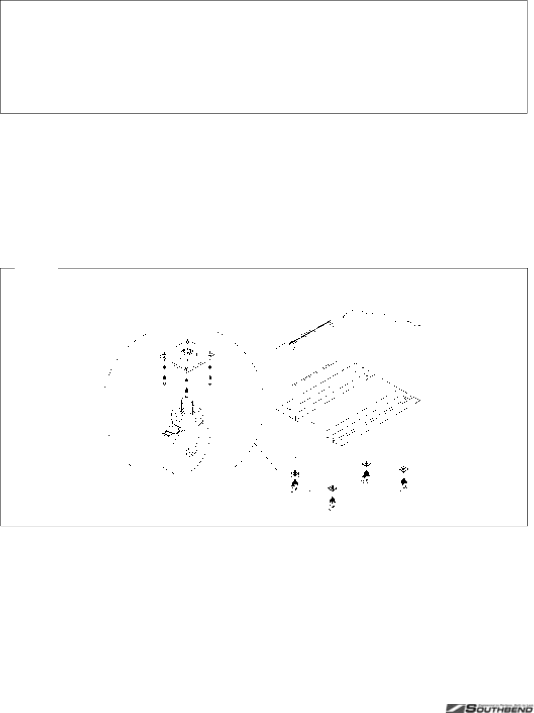
Fi
g
ure 12
Removal of Shipping Hold-Down Brackets
INSTALLATION PLATINUM SERIES SECTIONAL RANGE
PAGE 26 OF 80 INSTALL & OPERATIONS MANUAL 1185836 REV 3 (07/06)
STEP 2B: ATTACH CASTERS TO THE RANGE
NOTICE
For an appliance equipped with casters, (1) the installation shall be made with a connector that complies with the
Standard for Connectors for Movable Gas Appliances, ANSI Z21.69 or Connectors for Moveable Gas Appliances,
CAN/CGA-6.16, and a quick-disconnect device that complies with the Standard for Quick-Disconnect Devices for
Use With Gas Fuel, ANSI Z21.41, or Quick Disconnect Devices for Use with Gas Fuel, CAN1-6.9, (2) adequate
means must be provided to limit the movement of the appliance without depending on the connector and the
quick-disconnect device or its associated piping to limit the appliance movement and (3) the restraining means
should be attached to a frame member on the back of the unit.
A set of four casters is packed with units ordered with casters (instead of legs).
A threaded leg pad is fastened to the base frame at each corner. Each caster has a corresponding mating thread. The
casters can be adjusted to overcome a slightly uneven floor. Casters are provided with a Zerk fitting for proper
lubrication when required.
1. Raise unit sufficiently to allow the casters to be attached. For safety, “shore up” and support the range with an
adequate blocking arrangement strong enough to support the load.
2. Screw the casters into the holes in the centers of the leg pads (see Figure 14). Install the casters that have a
locking brake under the front of the range.
3. Lower the range gently onto a level surface. Never drop or allow the range to fall.
4. Go to Installation Step 3.
Fi
g
ure 14
Installation of Casters
1

PLATINUM SERIES SECTIONAL RANGE INSTALLATION
INSTALL AND OPERATIONS MANUAL 1185836 REV 3 (07/06) PAGE 27 OF 80
STEP 2C: MOUNT RANGE ON CASTER FRAME
NOTICE
For an appliance equipped with casters, (1) the installation shall be made with a connector that complies with the
Standard for Connectors for Movable Gas Appliances, ANSI Z21.69 or Connectors for Moveable Gas Appliances,
CAN/CGA-6.16, and a quick-disconnect device that complies with the Standard for Quick-Disconnect Devices for
Use With Gas Fuel, ANSI Z21.41, or Quick Disconnect Devices for Use with Gas Fuel, CAN1-6.9, (2) adequate
means must be provided to limit the movement of the appliance without depending on the connector and the
quick-disconnect device or its associated piping to limit the appliance movement and (3) the restraining means
should be attached to a frame member on the back of the unit.
The range can be mounted on an optional caster frame. The frame will have a threaded leg pad at each corner. Each
caster has a corresponding mating thread. The casters can be adjusted to overcome a slightly uneven floor. Casters
are provided with a Zerk fitting for proper lubrication when required.
1. Assemble the caster frame components.
2. Screw the casters into the holes in the centers of the leg pads of the caster frame. Install the casters that have a
locking brake under the front of the battery.
3. Lower the caster frame gently onto a level surface. Never drop or allow the frame to fall.
4. Block and brace the frame so that it will not move while the battery sections are installed on it.
5. Lift and gently place the range in position on the caster frame. Never drop or allow the range to fall.
6. Bolt the range to the caster frame.
7. Go to Installation Step 3.
STEP 3: ATTACH RESTRAINT TO RANGE (OR BATTERY) MOUNTED ON CASTERS
NOTICE
For an appliance equipped with casters, (1) the installation shall be made with a connector that complies with the
Standard for Connectors for Movable Gas Appliances, ANSI Z21.69 or Connectors for Moveable Gas Appliances,
CAN/CGA-6.16, and a quick-disconnect device that complies with the Standard for Quick-Disconnect Devices for
Use With Gas Fuel, ANSI Z21.41, or Quick Disconnect Devices for Use with Gas Fuel, CAN1-6.9, (2) adequate
means must be provided to limit the movement of the appliance without depending on the connector and the
quick-disconnect device or its associated piping to limit the appliance movement and (3) the restraining means
should be attached to a frame member on the back of the unit.
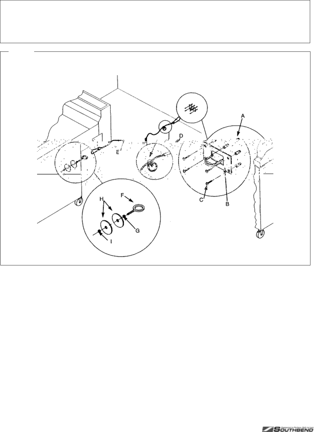
Install the restraint cable to a range (or battery) mounted on casters using the following procedure:
1. Secure the restraining-device bracket (item “B” in Figure 15) to a wall stud located as close as possible to the
appliance connector inlet and outlet connections. Use four #12 screws (items “C”) and plastic anchors (items “A”)
if necessary.
2. Install eye-bolt (item “F”) to a frame member on the rear of the equipment. After checking carefully behind the
frame member for adequate clearance, drill a 1/4" hole through the frame member.
3. Thread hex nut (item “G”) and slide the washer (item “H”) onto the eye-bolt. Insert the eye-bolt through the 1/4"
drilled hole and secure with a washer (item “H”) and nylon lock nut (item “I”).
4. Using the spring-loaded snap hooks, attach the restraining device to the bracket and the eye-bolt.
5. Using the cable clamp (item “D”), adjust the restraining device extended length to prevent over-bending or
kinking of the appliance connector.
For units not equipped with flame safety devices, be sure all valves are turned off prior to disconnecting. After
reconnecting, be sure all control knobs are turned off and all pilots are lit.
INSTALLATION PLATINUM SERIES SECTIONAL RANGE
PAGE 28 OF 80 INSTALL & OPERATIONS MANUAL 1185836 REV 3 (07/06)
NOTICE
Adequate means must be provided to limit the movement of the appliance without depending on the connector and
the quick-disconnect device or its associated piping to limit the appliance movement.
The restraining means should be attached to a frame member on the back of the unit.
Fi
g
ure 15
Installation of Cable Restraint
STEP 4: CONNECT BATTERY SECTIONS
If the range is part of a battery, and the battery was shipped partially disassembled, connect the battery sections using
the following procedure.
1. Remove valve panels from all sections. Mark them so that they can be returned to their respective section.
2. Position the center section of the battery and carefully level that unit. Use a long spirit level four ways; across
front top rail and the rear edge, and along each side edge.
3. If not already in place, attach pipe-union to front manifold of the battery. Screw it in far enough to be able to slide
the adjacent section into position.
4. Bring up adjacent section and level it using the same method and by using the center unit as reference. Match
front rails and rear edge. When a battery is set on a masonry base and legs are not used, shims may be used.
Special attention should be given to griddle ranges to allow proper drainage.
5. Bolt the frames of the sections together.
6. Connect the front manifolds using the pipe-union.
7. Attach the trim-strip between the section tops.
8. Install the continuous front-rail, if ordered.
9. Slide control knobs onto their shafts (to operate the sections during the installation procedure), but do not yet
reattach valve panels or front-panel trim pieces.
PLATINUM SERIES SECTIONAL RANGE INSTALLATION
INSTALL AND OPERATIONS MANUAL 1185836 REV 3 (07/06) PAGE 29 OF 80
STEP 5: ATTACH FLUE RISER AND SHELF ASSEMBLIES
Install the flue riser(s) using the following procedure (as shown in Figure 16).
1. Attach any salamander broilers and flue-riser-mounted cheese melters to appropriate sections following the
installation procedure in the manuals for those options.
2. Slide each flue riser down onto the brackets projecting from the back of the corresponding section(s) of the
sectional range. Secure the flue riser to the brackets with the four provided 1/4-20x3/4 hex-head bolts, flat
washers, and lockwashers. Also, secure the bottom edge of the flue riser to the top rear edge of the sectional
range using the provided #10 sheet metal screws.
3. If access to the interior of the flue riser is necessary to make gas connections, make those connections at this
time.
Fi
g
ure 16
Installation of Flue Riser

INSTALLATION PLATINUM SERIES SECTIONAL RANGE
PAGE 30 OF 80 INSTALL & OPERATIONS MANUAL 1185836 REV 3 (07/06)
4. Attach each wall shield to the back of the corresponding flue riser using the provided #10 sheet metal screws.
5. Connect the top side edges of adjoining flue risers using the provided small plates and screws.
6. If tubed shelves were installed, place the tubes in place in the shelf brackets.
7. If sloped enclosures were ordered (for flue-mounted salamander broilers and/or cheese melters), install them at
this time.
STEP 6: CONNECT ELECTRICITY (FOR SECTIONS WITH OVEN-BASES)
A wiring diagram is located behind the kick panel of the oven-base ranges. Be sure that the input voltage and phase
match the requirements shown on the serial plate.
Oven-base ranges ordered with a 115V, 60Hz, single-phase electrical rating are factory-supplied with a three-wire
cord with a three-prong plug that fits any standard three-prong grounded receptacle. Each standard oven requires a
15 ampere supply, while each convection oven requires a 20 ampere supply.
Oven-base ranges ordered with a 208/236V, 60Hz, single- or three-phase electrical rating are factory-equipped with
a two-pole terminal block located behind cover plate located on the rear of the unit. To connect the supply wires,
remove the cover plate. Route the supply wires and the grounding wire through the strain relief fitting to the terminal
block. Insert the supply wires, one each, into the two poles of the terminal block and tighten the screws. Insert the
ground wire into the grounding lug and tighten the screw. Re-attach the cover plate.
Three phase units are wired as above, using only two supply wires. The third wire is not used and must be properly
terminated.
All units are shipped wired as specified by factory order. Conversion between single-phase and three-phase can be
accomplished by referring to phase loading and line amperes chart on the wiring diagram for wire size and ampere
requirements.
STEP 7: CONNECT GAS SUPPLY
If the sectional range is being installed at over 2,000 feet altitude and that information was not specified when
ordered, contact the appropriate authorized Southbend Service Representative or the Southbend Service
Department. Failure to install with proper orifice sizing will result in poor performance and may void the warranty.
The sectional range is design-certified for operation on natural or propane gases. The sectional range is shipped
configured and adjusted for the type of gas specified by the purchaser, which is indicated on the serial plate (see
Figure 1 on page 3). Connect the sectional range ONLY to the type of gas for which it is configured and adjusted.
Minimum supply pressure is 7" W.C. for natural gas, 11" W.C. for propane. An external pressure regulator and shut off
valve are provided. If using a flexible-hose gas connection, the I.D. of the hose must not be smaller than the
connector on the sectional range, and must comply with ANSI Z21.69. Provide an adequate means of restraint to
prevent undue strain on the gas connection.
If applicable, the vent line from the gas pressure regulator shall be installed to the outdoors in accordance with local
codes, or in the absence of local codes, with the National Fuel Gas Code, ANSI Z223.1, Natural Gas Installation
Code, CAN/CGA-B149.1, or the Propane Installation Code CAN/CGA-B149.2, as applicable.
An adequate gas supply is imperative. Undersized or low pressure lines will restrict the volume of gas required for
satisfactory performance. Fluctuations of more than 25% on natural gas or 10% on propane gas will create problems
and affect burner operating characteristics. A 1/8" pressure tap is located on the manifold to measure the manifold
pressure. The supply line to the sectional range should be no smaller than the inside diameter of the pipe on the
sectional range to which it is connected.
CAUTION
ALL PIPE JOINTS AND CONNECTIONS MUST BE TESTED THOROUGHLY FOR GAS LEAKS. USE ONLY
SOAPY WATER FOR TESTING ON ALL GASES. NEVER USE AN OPEN FLAME TO CHECK FOR GAS LEAKS.
ALL CONNECTIONS MUST BE CHECKED FOR LEAKS AFTER THE APPLIANCE HAS BEEN PUT INTO
OPERATION. TEST PRESSURE SHOULD NOT EXCEED 14" W.C.
Do the following to connect the gas supply:
1. Check that all control knobs on the sectional range are in the OFF position.
2. Purge the gas supply line to clean out dust, dirt, or other foreign matter before connecting the line to the sectional
range.

PLATINUM SERIES SECTIONAL RANGE INSTALLATION
INSTALL AND OPERATIONS MANUAL 1185836 REV 3 (07/06) PAGE 31 OF 80
3. The gas connection piping may have been partially installed at the factory. If necessary, attach the gas
connection of any appliances mounted on a flue riser.
4. Locate the pressure regulator(s) packed with the sectional range. Install the pressure regulator, taking care that
the direction of gas flow corresponds to the arrow on the side of the pressure regulator.
CAUTION
HOLD THE PRESSURE REGULATOR WITH A WRENCH WHEN TIGHTENING THE CONNECTION TO THE
SUPPLY PIPE TO AVOID DAMAGE TO THE REGULATOR, VALVE, AND OTHER COMPONENTS.
5. Install a service shut-off valve to the pressure regulator, and connect the gas supply line to the shut-off valve.
6. If applicable, install the vent line of the pressure regulator to the outdoors.
7. Turn on the gas and immediately check for leaks using soapy water.
8. If the optional sloped enclosure for a flue-mounted model was ordered, install it at this time.
STEP 8: CONNECT WATER SUPPLY
If a rail-mounted fill-hose was ordered (as a special option), there will be a corresponding water connection on the
back of the section. Connect the water supply.
STEP 9: CHECK THE INSTALLATION
Check the installation, as follows:
1. Check that all screws and bolts are tightened.
2. Check electrical connection(s).
3. Check that the gas connection has been made correctly.
4. Check water connection(s).
5. Move the battery into the final position at which it will be operated.
6. Check that the battery is level. If not, adjust the legs or casters.
7. Check that the appropriate minimum clearances are satisfied (see page 4).
8. Check that there is sufficient clearance to open all doors and pull-out all grease trays and crumb trays.
9. Check that adequate ventilation (fresh air supply and hood exhaust) is available to the room in which the
appliance will operate.
10. Wipe clean all cooking surfaces (especially griddles).
11. Check that nothing is obstructing the air intake openings and/or the combustion-exhaust openings.
STEP 10: CHECK OPERATION OF EACH SECTION
Check the operation of each section, as follows:
1. Turn electricity supply on.
2. Turn gas supply on. Immediately check all gas connections for leaks using soapy water.
3. Turn water supply on (if applicable). Check for water leaks.
4. Light all pilots (see the appropriate Operation section elsewhere in this manual). Start with the section(s) furthest
from the gas supply connection(s) to purge air from the gas lines. Check all pilots for correct flame height.
5. Turn on the burners of each section using only the lowest temperature settings (for now). Check all burners for
correct flame appearance and height.
6. Begin to break-in all griddle surfaces by turning on all griddle burners to LOW for at least one hour. (In case any
problems occur, do not leave the battery unattended during this time!) This will temper the griddle surface and
avoid possible damage.
7. Check operation of all sections (except griddles) for the full-range of operating settings, including checking all
burners for correct flame appearance and height at the HIGH settings.
8. Complete the break-in of all griddle surfaces (after they have been operating at LOW for at least one hour) by
gradually bringing each griddle up to frying temperature. Then spread over each griddle three or four ounces of

INSTALLATION PLATINUM SERIES SECTIONAL RANGE
PAGE 32 OF 80 INSTALL & OPERATIONS MANUAL 1185836 REV 3 (07/06)
beef suet, or as a substitute, baking soda, to season it. Never allow water on a hot griddle and never wash it with
soap and water.
9. Check that gas supply is adequate by simultaneously turning on all burners of all sections to their highest setting,
then again checking that all burner flames have correct appearance and height.
10. Check that electricity supply is adequate by simultaneously turning on all electrical elements (if any) and turning
the blower setting of all convection ovens (if any) to HIGH.
11. Check that water supply is adequate by simultaneously operating all fill hoses (if any). (Do not allow water to
spill onto a hot griddle.)
12. Turn-off all burners and allow all battery sections to cool.
STEP 11: ATTACH VALVE-PANEL(S) AND FRONT TRIM PANELS
Attach the valve panel(s) and front trim panels, as follows:
1. After the battery has cooled, again check all gas connections for gas leaks using soapy water.
2. Attach the front-trim panels for the adjoining sections.
3. Remove control knobs, grease drawers, and drippings-trays as necessary to enable installation of the valve
panel(s).
4. Attach the valve panel(s).
5. Re-attach the control knobs. Insert all grease drawers and drippings trays.
STEP 12: WIPE-CLEAN AND SHUT-DOWN RANGE
Complete the installation by leaving the sectional range ready for customer use:
1. Wipe clean all surfaces.
2. Unless the sectional range is to be placed in service immediately, shut off the gas, electricity, and water supplies.
3. Make sure that a copy of this manual will be available to the people who will operate and maintain the sectional
range.

PLATINUM SERIES SECTIONAL RANGE SERVICE
INSTALL AND OPERATIONS MANUAL 1185836 REV 3 (07/06) PAGE 33 OF 80
SERVICE
WARNING
ADJUSTMENTS AND SERVICE WORK MAY BE PERFORMED ONLY BY A QUALIFIED TECHNICIAN WHO IS
EXPERIENCED IN, AND KNOWLEDGEABLE WITH, THE OPERATION OF COMMERCIAL COOKING
EQUIPMENT. TO ASSURE YOUR CONFIDENCE, CONTACT YOUR AUTHORIZED SERVICE AGENCY FOR
RELIABLE SERVICE, DEPENDABLE ADVICE OR OTHER ASSISTANCE, AND FOR GENUINE FACTORY
PARTS.
NOTICE
INSTALLATION OF OTHER THAN GENUINE SOUTHBEND PARTS WILL VOID THE WARRANTY ON THIS
EQUIPMENT.
The location of the serial plate depends on the type of base (see Figure 1 on page 3). On models with oven bases,
the serial plate is located on the backside of the kick-plate below the oven door (lift the kick-plate straight up and tilt
the top edge out and down.) On models with a cabinet base, the serial plate is located inside the left cabinet door. On
modular (countertop) models, the serial plate is located inside the front valve panel.
Replacement parts (including parts not listed in this manual) may be ordered either through a Southbend Authorized
Parts Distributor or a Southbend Authorized Service Agency.
When ordering parts, please supply the Model Number, Serial Number, Part Number, and Part Description.
ACCESS TO SERVICEABLE COMPONENTS
To open the kick panel below the oven door, lift the kick panel straight up and pull the top edge away from the oven.
The kick panel is hinged at the bottom corners.
To remove the valve panel, first remove the knobs. Then remove the two screws on the bottom of the valve panel
(except on modular-countertop base models). Pull the bottom of the valve panel away from the range. The top edge of
the valve panel has two small slots that hook over tabs on the frame.
To access the rear of the oven control panel, first remove the valve panel. Then remove the screw that holds the top
of the oven control panel in place. Tilt the top of the oven control panel outward, being careful not to damage the wires
or the thermostat sensor.
To service the blower motor from the front of the oven, first remove the blower baffle from the rear of the oven cavity
(lift it up and out). Then disconnect the motor-mount plate by removing the eight hex nuts that secure it to the oven
interior back. Pull the mount-plate, with motor attached, into the oven cavity.

SERVICE PLATINUM SERIES SECTIONAL RANGE
PAGE 34 OF 80 INSTALL & OPERATIONS MANUAL 1185836 REV 3 (07/06)
TROUBLESHOOTING BURNERS AND PILOTS
The following table lists the possible causes of burner and pilot related problems that may occur.
Problem Look for -
None of the burners and pilots will turn on – Main gas supply to unit is OFF.
All burners produce excessive carbon deposits – Incorrect gas type is being supplied to the range.
– Incorrect gas supply pressure.
Only some burners produce excessive carbon deposits – Incorrect orifices.
– Primary air not adjusted properly.
Only some pilots produce excessive carbon deposits – Pilot not adjusted properly.
– Incorrect pilot orifice.
Top burner (not oven) will not come on – Pilot out.
– For thermostatic griddles, gas shut off valve is in OFF position.
– For thermostatic griddles, button on safety switch is not being
held in long enough after lighting pilot.
Top section pilot will not remain lit – Pilot flame not adjusted properly.
– Clogged orifice.
– Draft condition.
– Improper ventilation system.
– Air in gas line.
SERVICING BURNERS AND PILOTS
All orifice sizes and burner rates are properly set at the factory and should not be altered.
Each burner should have a steady blue flame on each port of the burner. When using propane, the burners may have
a small amount of yellow tipping.
If the flame is rising up off of the ports adjust the burner shutter to be further closed. If the flame is long and yellow
adjust the burner shutter to be further open.
Over-gassed burners DO NOT heat as efficiently as those that are properly adjusted. Such conditions also create “hot
spots” on griddles and hot tops. Floating and unstable burner and pilot flames will result when solid tops are lowered
into position because the rear openings of the burner compartment are not adequate to vent the enormous flue
products generated by over-gassed burners. The “unburned” gas will ignite at the rear and burn in this section and
even up inside the flue riser, causing structural members in this area to deteriorate. Also, some of these hot flue
products will vent forward into the manifold compartment resulting in problems with valves and thermostats due to
overheating. AGAIN, over-gassed burners waste energy and cause service problems.
Note that the burners of griddle, charbroiler, and uniform hot-top models are long, and so the burner flame may float
when cold. Allow the burner to heat before making burner adjustments.
Propane burners may have a slight popping noise when turned off. This is normal.
Check that the burner is level and in its support brackets.
Check that the burner is clean and all of its ports are clear.
Check that each burner valve and orifice is in alignment with the burner.
Remove the burner and check that its venturi is clean and free of buildup and debris.
With each burner removed check that the orifice size is correct and clean and free of buildup and debris.
If it is necessary to remove a griddle top to service the burners, use extreme care since the griddle plate is very
heavy. When raising a thermostatic griddle top, remove the thermostat bulbs from the tubes on the bottom of the
griddle plate. When re-installing, re-insert the thermostat bulbs and be sure the capillary tubes are away from burners,
flames and excessive heat.
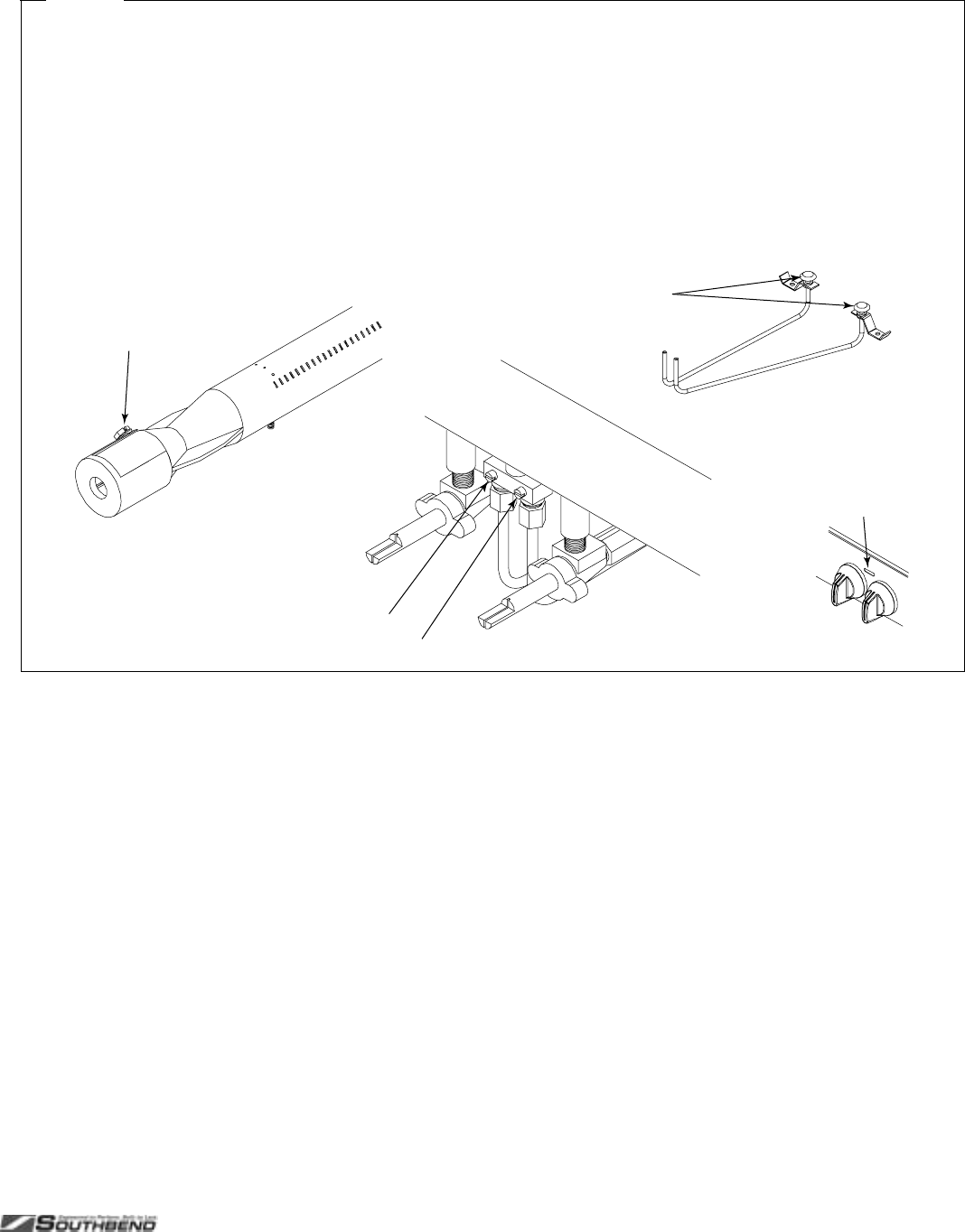
PLATINUM SERIES SECTIONAL RANGE SERVICE
INSTALL AND OPERATIONS MANUAL 1185836 REV 3 (07/06) PAGE 35 OF 80
Pilot-flame outage is often due to an unstable flame caused by over-adjustment to the point where the pilot flame is
leaving its port, or “blowing off.” Sometimes the pilots are increased too much in an effort to improve ignition, resulting
in this unstable condition.
Fi
g
ure 17
Adjustment of Charbroiler, Standard-Griddle, and Uniform Hot-Top Burners and Pilots
The burner valves are not adjustable. The burner orifice is of the fixed type, sized for the type of gas and the operating altitude.
To adjust the burner air-gas mixture, loosen the screw that secures the air shutter on the mixer face and rotate the mixer cap
to obtain a clear, stable blue flame with a distinct inner cone at each port. Excessive primary air causes “blowing” (the flames
leaving the ports), while insufficient primary air causes a soft or yellow tipped flame.
The pilots are near the front of the burners, and are held in position by brackets. To adjust a pilot flame, insert a screwdriver
through the opening in the valve panel between the control knobs and turn the appropriate pilot adjustment screw
counterclockwise to increase the size of the pilot flame, or clockwise to decrease the size of the pilot flame. The maximum
flame size is approximately 3/4" with a slight yellow tip. The first indication of over-adjustment is when the flame tip becomes
more yellow and begins to generate carbon, which appears as rising black streaks. Continued over-adjustment leads to
unstable lifting and a blowing condition.
Adjustment screw for left-burner pilot
Air Shutter
Access hole
for pilot
adjustment
Adjustment screw for right-burner pilot
Pilots
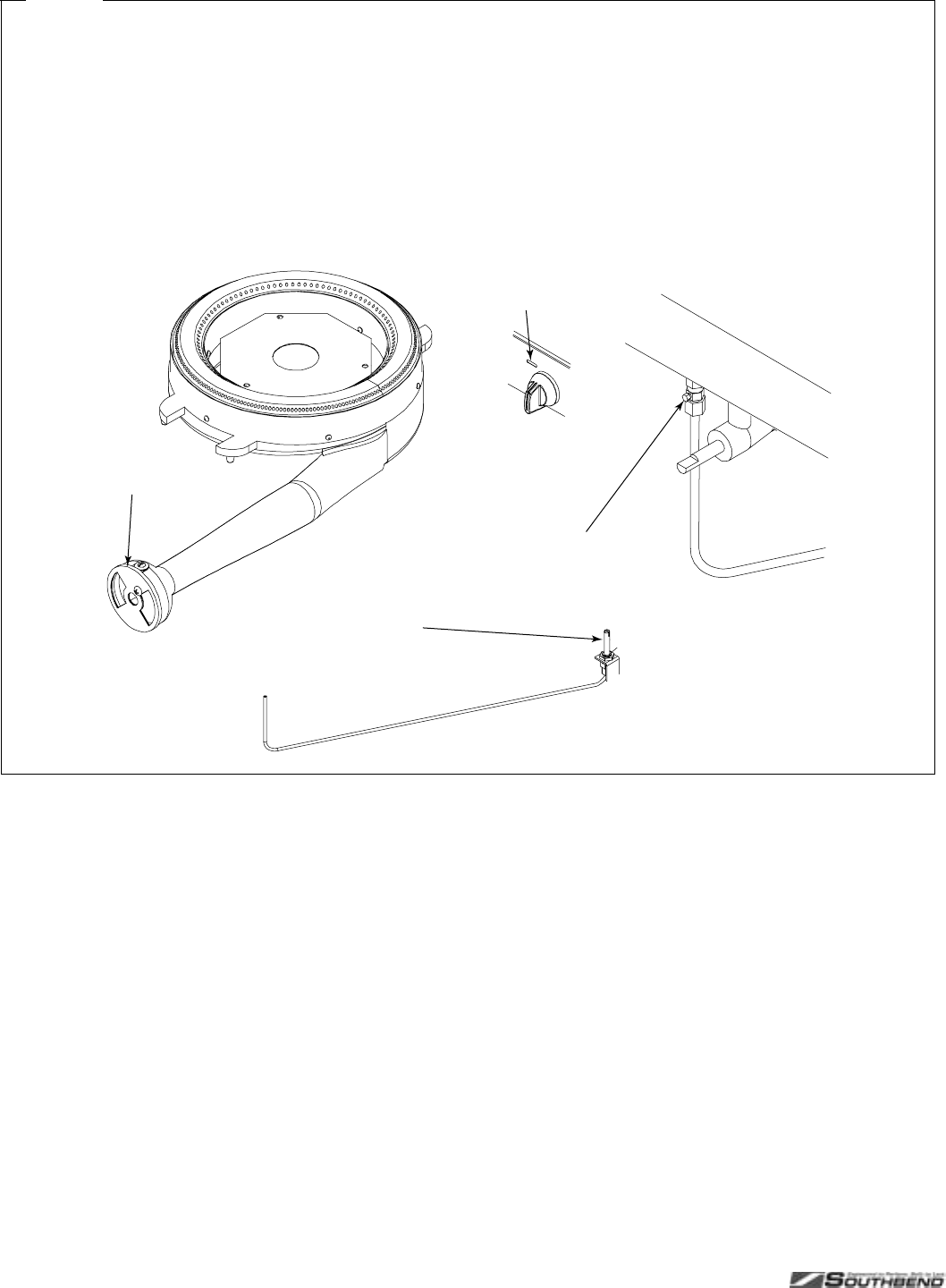
SERVICE PLATINUM SERIES SECTIONAL RANGE
PAGE 36 OF 80 INSTALL & OPERATIONS MANUAL 1185836 REV 3 (07/06)
Fi
g
ure 18
Adjustment of Graduated Hot-Top Pilot and Burner
The burner valves are not adjustable. The burner orifice is of the fixed type, sized for the type of gas and the operating altitude.
To adjust the burner air-gas mixture, loosen the screw that secures the air shutter on the mixer face and rotate the mixer cap
to obtain a clear, stable blue flame with a distinct inner cone at each port. Excessive primary air causes “blowing” (the flames
leaving the ports), while insufficient primary air causes a soft or yellow tipped flame.
The pilot is beside the burner, and is held in position by a bracket. To adjust the pilot flame, insert a screwdriver through the
opening in the valve panel beside the control knob and turn the pilot adjustment screw counterclockwise to increase the size of
the pilot flame, or clockwise to decrease the size of the pilot flame. The maximum flame size is approximately 3/4" with a slight
yellow tip. The first indication of over-adjustment is when the flame tip becomes more yellow and begins to generate carbon,
which appears as rising black streaks. Continued over-adjustment leads to unstable lifting and a blowing condition.
Adjustment screw for pilot
Air Shutter
A
ccess hole
for pilot
adjustment
Pilot
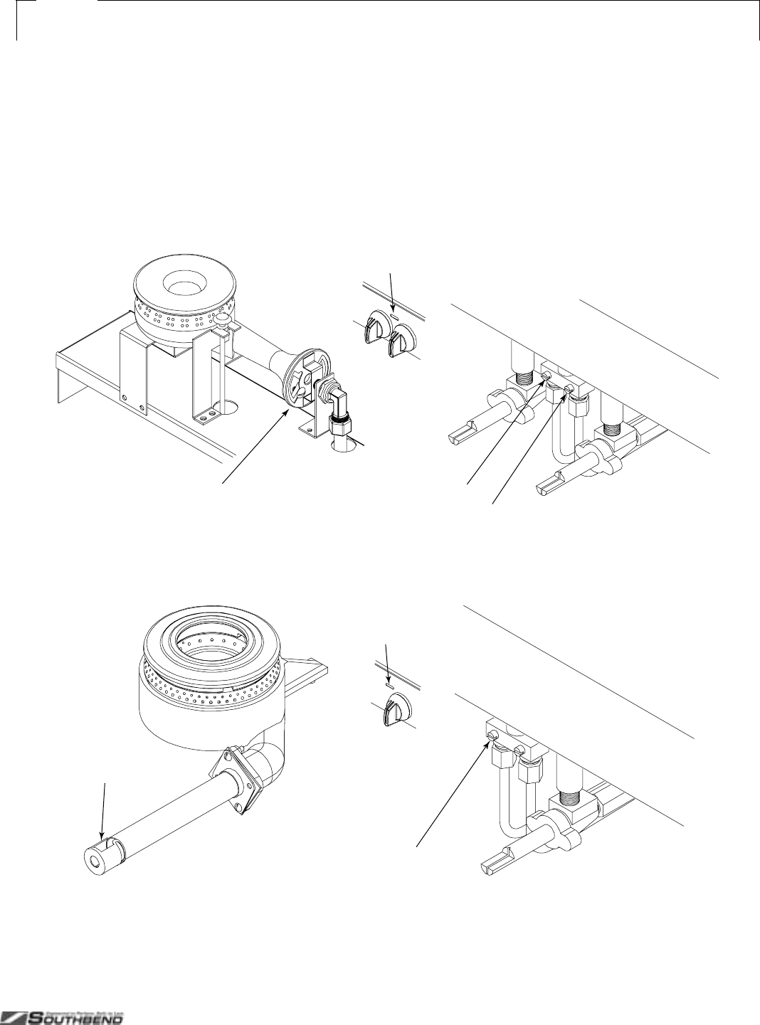
PLATINUM SERIES SECTIONAL RANGE SERVICE
INSTALL AND OPERATIONS MANUAL 1185836 REV 3 (07/06) PAGE 37 OF 80
Fi
g
ure 19
Adjustment of 33K and 45K Open-Top Burners and Pilots
The burner valves are not adjustable. The burner orifice is of the fixed type, sized for the type of gas and the operating altitude.
To adjust the burner air-gas mixture, loosen the screw that secures the air shutter on the mixer face and rotate the mixer cap
to obtain a clear, stable blue flame with a distinct inner cone at each port. Excessive primary air causes “blowing” (the flames
leaving the ports), while insufficient primary air causes a soft or yellow tipped flame.
The pilots are beside the burners, and are held in position by brackets. To adjust a pilot flame, insert a screwdriver through the
opening in the valve panel between the control knobs and turn the appropriate pilot adjustment screw counterclockwise to
increase the size of the pilot flame, or clockwise to decrease the size of the pilot flame. The maximum flame size is
approximately 3/4" with a slight yellow tip. The first indication of over-adjustment is when the flame tip becomes more yellow
and begins to generate carbon, which appears as rising black streaks. Continued over-adjustment leads to unstable lifting and
a blowing condition.
33K-Open-Burner Model
s
Adjustment screw for rear-burner pilot
Air Shutter
Access hole
for pilot
adjustment
Adjustment screw for front-burner pilot
Adjustment screw for rear-burner pilot
Air Shutter
Access hole
for pilot
adjustment
Adjustment screw for front-burner pilot
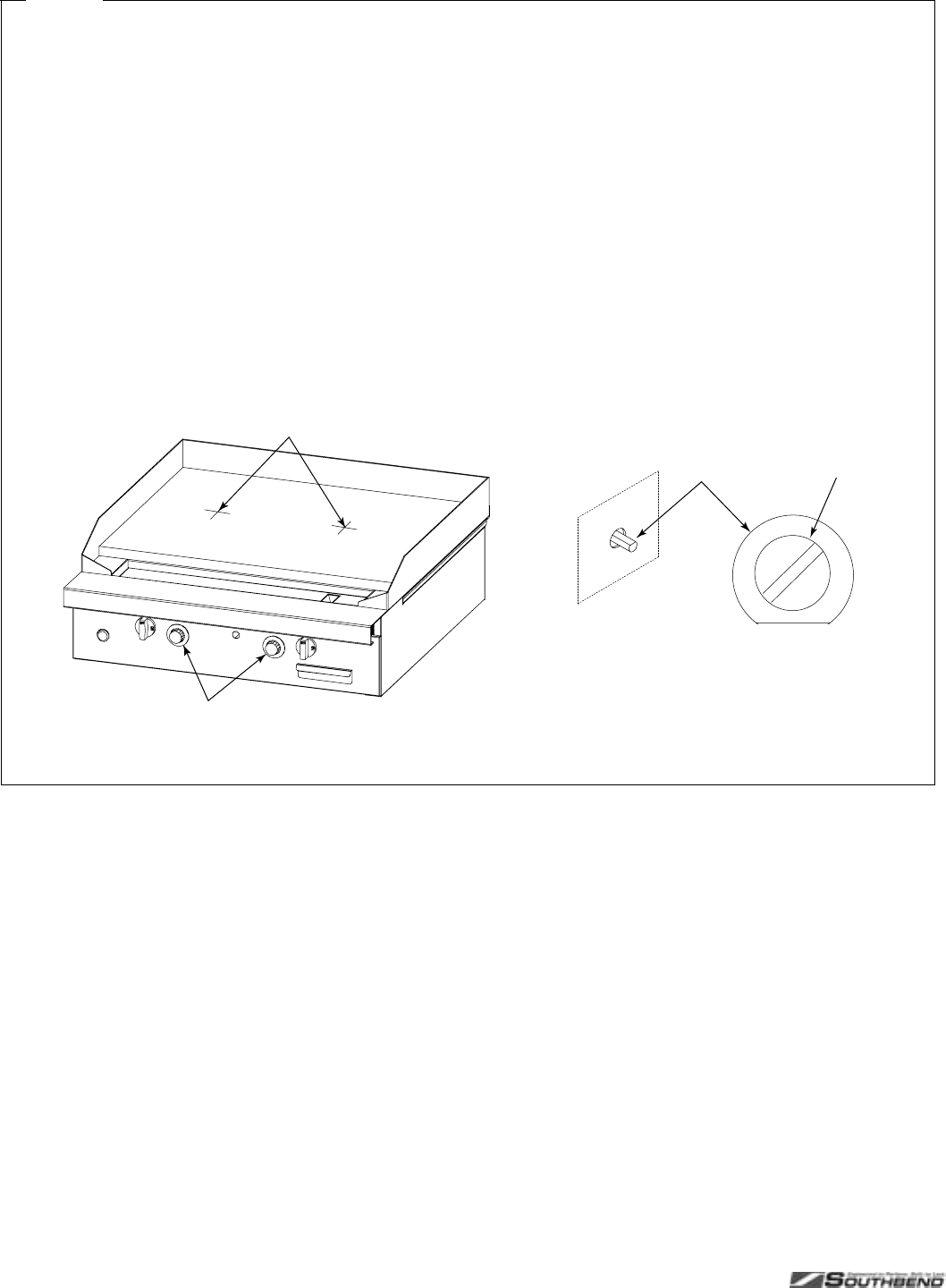
SERVICE PLATINUM SERIES SECTIONAL RANGE
PAGE 38 OF 80 INSTALL & OPERATIONS MANUAL 1185836 REV 3 (07/06)
Fi
g
ure 20
Adjustment of Thermostatic-Griddle Thermostat
Each 16"-wide section of a thermostatic griddle has a control knob that operates a snap-action thermostatic valve. Each valve
is adjusted at the factory. If the griddle surface temperature is different from the thermostat dial setting, adjust the thermostatic
valve using the following procedure:
1. Turn all the control knobs to the 300°F.
2. Wait 30 minutes for the griddle temperature to stabilize (or 1 hour if the griddle was cold).
3. Place a reliable thermometer or test-instrument thermocouple (able to register 300°F) halfway back from the front to the
back of the griddle and directly in line with the 16"-wide section’s control knob (see drawing below). Check the temperature
of each section every five minutes until the temperature does not change by more than 30°F between two consecutive
measurements.
4. If the average temperature of any section is not within 30°F of the knob setting (300°F), adjust the corresponding
thermostatic valve. To do so, remove the control knob (being careful to not turn the stem, which would change the
temperature setting). While holding the stem in place, turn the calibration screw (see drawing below). If the actual
measured temperature is lower than the dial setting, turn the screw counterclockwise. If the measured temperature is
higher than the dial setting, turn the screw clockwise. Replace the control knob.
5. Wait for the griddle temperature to stabilize, then again check the temperature (as described above).
Measure temperature of each 16"-wide section
half-way back and in line with control knob.
Each knob is attached to a thermostatic
valve located behind the valve panel.
Calibrate the thermostat by holding the
shaft in place while turning the screw
counterclockwise to increase the temperature,
or clockwise to decrease the temperature.
With a control knob removed,
its valve shaft will extend out
of the valve panel.
Shaft Screw
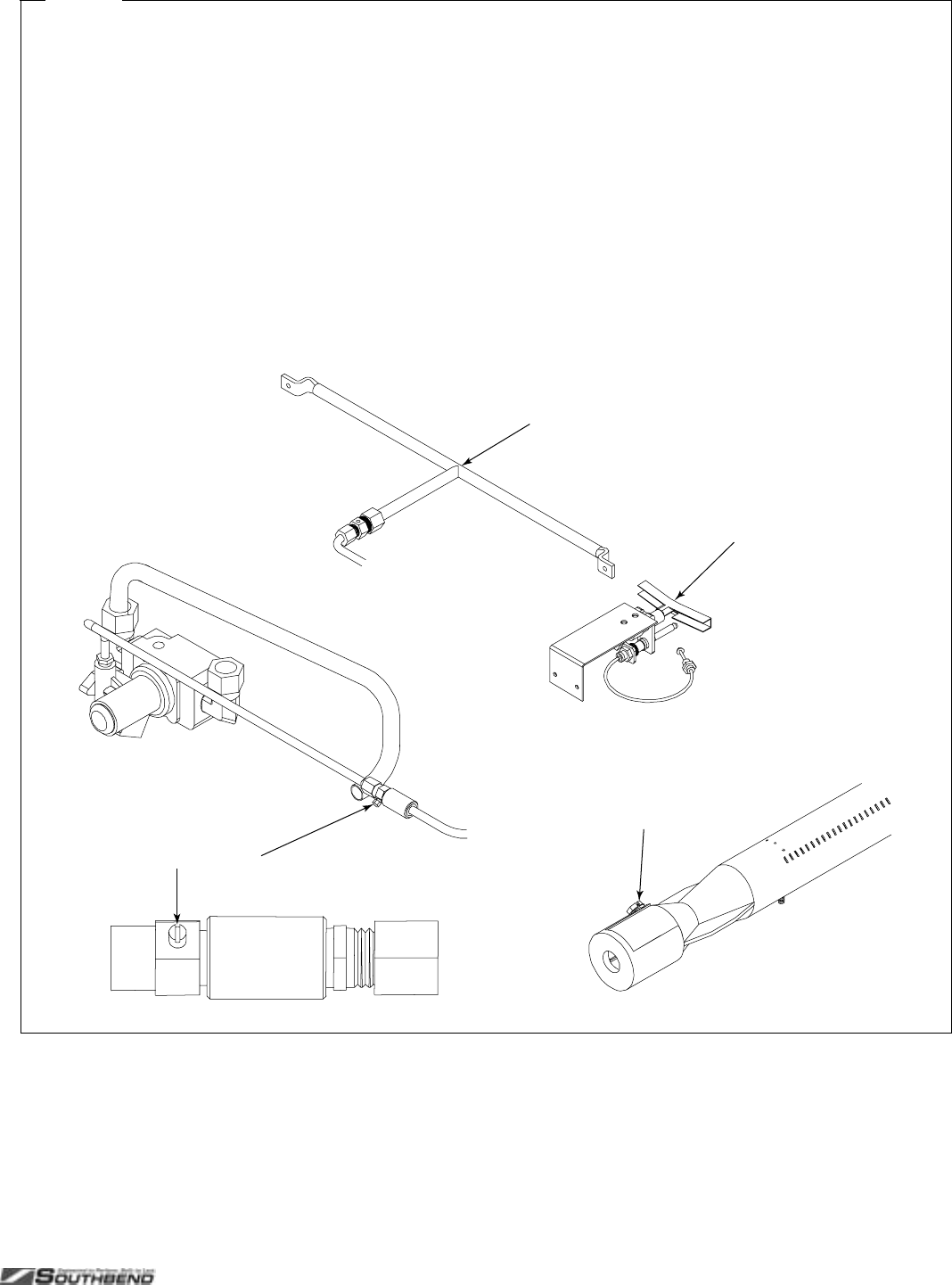
PLATINUM SERIES SECTIONAL RANGE SERVICE
INSTALL AND OPERATIONS MANUAL 1185836 REV 3 (07/06) PAGE 39 OF 80
Fi
g
ure 21
Adjustment of Thermostatic-Griddle Burners and Pilot
The thermostatic burner valve is adjustable (see page 38). The burner orifice is of the fixed type, sized for the type of gas and
the operating altitude. To adjust the burner air-gas mixture, loosen the screw that secures the air shutter on the mixer face and
rotate the mixer cap to obtain a clear, stable blue flame with a distinct inner cone at each port. Excessive primary air causes
“blowing” (the flames leaving the ports), while insufficient primary air causes a soft or yellow tipped flame.
The pilot(s) and pilot-runner(s) are located near the front of the burners, but the pilot adjustment valve is located in the gas line
between the safety switch and the pilot. If the pilot needs adjustment, do the following:
1. Remove the control knobs, and remove the valve panel (see page 33).
2. If necessary, light the pilot.
3. Locate the pilot adjustment valve (see drawing below). Turn the pilot adjustment screw counterclockwise to increase the
size of the pilot flame, or clockwise to decrease the size of the pilot flame. The pilot flame should be about 1/2" high with a
slight yellow tip, and cover the thermocouple tip. The first indication of over-adjustment is when the flame tip becomes more
yellow and begins to generate carbon, which appears as rising black streaks. Continued over-adjustment leads to unstable
lifting and a blowing condition.
4. Replace the valve panel and control knobs.
Adjustment screw for pilot
Air Shutter
Pilot
Pilot Runner
SERVICE PLATINUM SERIES SECTIONAL RANGE
PAGE 40 OF 80 INSTALL & OPERATIONS MANUAL 1185836 REV 3 (07/06)
TROUBLESHOOTING OVEN
CAUTION
Proper and efficient operation of oven is dependent on correct installation and function of components. Always
verify that components are in place and functioning as intended.
The following table lists the possible causes of oven-related problems that may occur.
Problem Look for -1
Oven will not come on. – Oven gas shut-off valve is OFF
– Power switch is OFF
– Problem with power switch
– Problem with pilot solenoid
– Problem with main gas solenoid
– Problem with wiring
– Problem with spark ignition module
– Problem with flame sensor switch
Oven pilot will not light – Oven gas shut-off valve is OFF
– Problem with power switch
– Problem with pilot solenoid
– Problem with wiring
– Problem with spark ignition module
Convection blower motor will not run – Problem with fan speed switch
– Problem with door switch
– Problem with blower motor
– Problem with wiring
Oven will not maintain set temperature – Problem with oven thermostat
– Problem with door switch
Oven door too difficult to lift – Problem with door spring
– Problem with door roller assembly
SERVICING CONVECTION OVEN BLOWER MOTOR
WARNING
Before attempting to service or replace any electrical component, make sure that the power source has been
disconnected.
CAUTION
When changing motor or servicing unit, always verify that blower wheel rotation is clockwise when looking into the
oven cavity.
The motor is serviceable from the front of the unit through the oven cavity (see page 33).
Motor lubrication information can be found on the permanent label located on the motor.
If the blower does not run at all, consult the wiring diagrams in this manual (see page 44), or behind the oven kick
plate.
If the blower runs intermittently, consult the following flowchart.
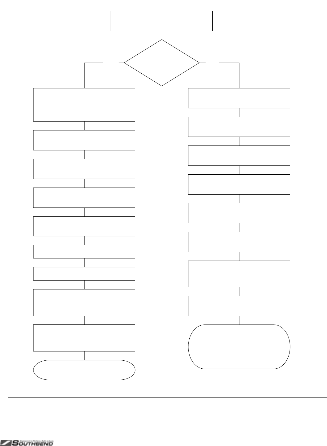
PLATINUM SERIES SECTIONAL RANGE SERVICE
INSTALL AND OPERATIONS MANUAL 1185836 REV 3 (07/06) PAGE 41 OF 80
Hot
BLOWER RUNS
INTERMITTENTLY
Check that the vents at each end o
f
the motor are not obstructed.
Check that the motor is not against
a wall.
Go to the junction box on the back
of the range and remove the cover.
Place a DVM or ammeter on the
black wire #1.
Check for excessive heat sources
behind the range.
Check for hot air leaks around the
motor pocket.
Cold
Check all wiring for loose
connections or breaks.
REMOVE THE MAIN POWER
SOURCE. UNPLUG OR
DISCONNECT CIRCUIT
BREAKER.
CAUTION! Be sure a DVM is
protected to 40 amps or greater.
Connect main power supply.
Turn on the oven Power Switch.
Observe that the amperage surges
and returns to the motor amperage
reading for high speed.
If the motor shuts off and there
is no excessive heat around the
blower motor it must be
re
p
laced.
If the amperage surge remains at a
value greater than the rating
replace the motor.
Test oven.
Check that there are no air flow
obstructions around the range.
Check for excessive grease and
dust buildup on the motor.
Leave the blower turned on and
turn off the oven thermostat and
allow to cool.
If the blower starts up turn the oven
on and allow to reheat to 500°F.
Blower
starts but
shuts off.

SERVICE PLATINUM SERIES SECTIONAL RANGE
PAGE 42 OF 80 INSTALL & OPERATIONS MANUAL 1185836 REV 3 (07/06)
Fi
g
ure 22
Adjustment of Oven Thermostat
The oven thermostat is carefully calibrated at the factory so that the dial setting matches the actual oven temperature. Field
recalibration is seldom necessary, and should not be resorted to unless considerable cooking experience definitely proves that
the control is not maintaining the temperatures to which the dial is set.
Obtain a test instrument or a reliable mercury thermometer, then do the following:
1. Place the thermocouple of test instrument or the thermometer in the middle of the oven.
2. Turn on the oven and set the thermostat to 400°F.
3. After the oven has been on about 20 minutes check oven temperature. The oven door should be open for as short a time
as possible. Use a flashlight, if necessary, to see the thermometer clearly.
4. Continue to check the temperature at 5-minute intervals until two successive readings are within 5 degrees of each other.
The thermostat should be recalibrated if the reading is not within 20 degrees of the dial setting (400°F). If calibration is
required, adjust the thermostat, as follows:
5. Remove the oven temperature control knob. Be careful to not turn the stem (which would change the temperature setting).
6. While holding the stem in place, turn the calibration screw (see drawing below). If the actual measured temperature is lower
than the dial setting, turn the screw counterclockwise. If the measured temperature is higher than the dial setting, turn the
screw clockwise. Replace the control knob.
7. Set the oven temperature to 450°F. After about 20 minutes, check the oven temperature. Continue to check the
temperature at 5-minute intervals until two successive readings are within 5 degrees of each other. If the actual oven
temperature is not within 20 degrees of the dial setting (450°F), replace the thermostat.
Calibrate the thermostat by holding the
shaft in place while turning the screw
counterclockwise to increase the temperature,
or clockwise to decrease the temperature.
With the control knob removed,
the control shaft will extend out
of the control panel.
Remove oven thermostat
control knob.
Shaft Screw
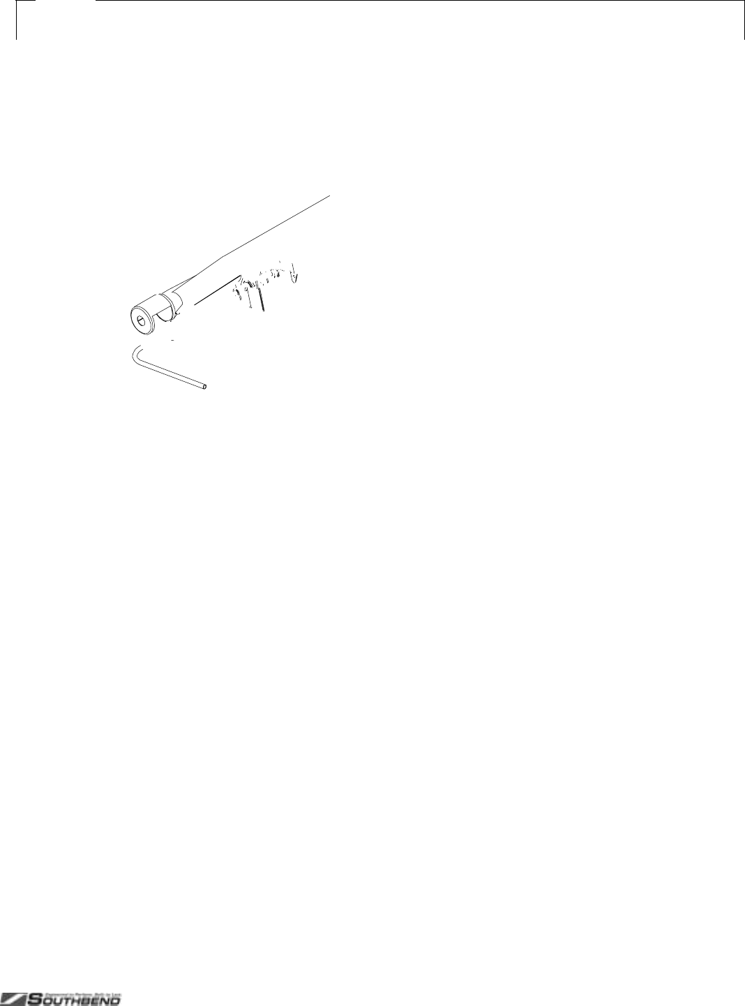
PLATINUM SERIES SECTIONAL RANGE SERVICE
INSTALL AND OPERATIONS MANUAL 1185836 REV 3 (07/06) PAGE 43 OF 80
Fi
g
ure 23
Adjustment of Oven Pilot and Burner
The burner orifice is of the fixed type, sized for the type of gas and the operating altitude. To adjust the burner air-gas mixture,
loosen the screw that secures the air shutter on the mixer face and rotate the mixer cap to obtain a clear, stable blue flame
with a distinct inner cone at each port. Excessive primary air causes “blowing” (the flames leaving the ports), while insufficient
primary air causes a soft or yellow tipped flame.
The oven pilot flame is adjusted by using a screwdriver to turn the adjusting screw on the pilot line valve (see drawing below).
The pilot line valve is located behind the kick panel below the oven door. To gain access, lift the kick panel straight up and pull
the top edge out. The pilot flame is properly adjusted when it is just large enough to maintain a glowing red color of the flame
switch capillary bulb. The first indication of over-adjustment is when the flame tip becomes yellow and begins to generate
carbon, which appears as rising black streaks. Continued over-adjustment leads to unstable lifting and a blowing condition.
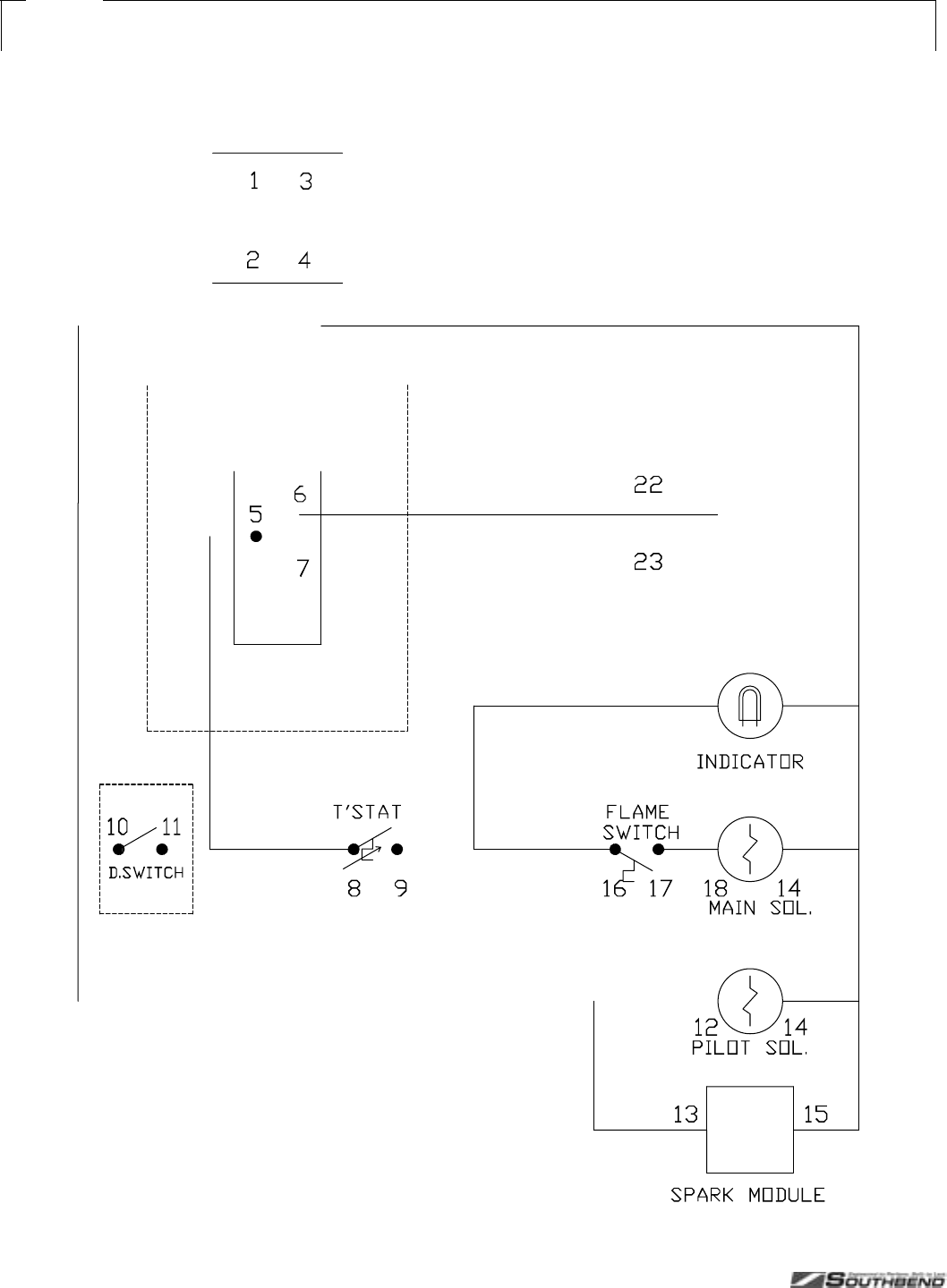
SERVICE PLATINUM SERIES SECTIONAL RANGE
PAGE 44 OF 80 INSTALL & OPERATIONS MANUAL 1185836 REV 3 (07/06)
Fi
g
ure 24
Wiring Diagram for 120 Volt Oven Bases
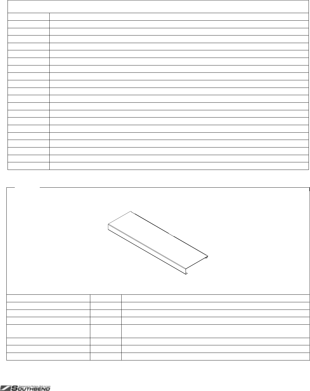
PLATINUM SERIES SECTIONAL RANGE SERVICE
INSTALL AND OPERATIONS MANUAL 1185836 REV 3 (07/06) PAGE 45 OF 80
PARTS
The following tables and figures list serviceable parts. For parts not listed, contact a Southbend Authorized Parts
Distributor or a Southbend Authorized Service Agency.
Index of Parts Diagrams
Page Number Description
45 Front-Rail Parts
46 33K-Open-Burner External and Structural Parts
48 33K-Open-Burner Gas Train Parts
50 45K-Open-Burner Parts
52 Charbroiler External and Structural Parts for 16" and 32" Models
54 Charbroiler External and Structural Parts for 24", 36", and 48" Models
58 Charbroiler and Standard-Griddle Gas Train Parts
59 Gas Connection Parts
60 Griddle External and Structural Parts
62 Thermostatic Griddle Gas Train Parts
64 Uniform Hot-Top Parts
66 Graduated-Hot-Top Parts
68 Oven Base Parts
70 Convection Oven Blower Parts
71 Modular-Countertop Base Parts
72 Cabinet-Base Parts
74 Flue Riser Parts
76 Shelf Parts
77 Side Panel and Battery-Assembly Parts
78 Leg and Caster Parts
Fi
g
ure 25
Front-Rail Parts
For custom front rails, or continuous rails spanning multiple sections, contact Southbend.
Models Part Number Description
P12_-B 1184718 FRONT RAIL, 9-1/4"
P16_-H, P16_-X 1185856 FRONT RAIL, 9-1/4"
P16_-C, P16_-G, P16_-T 1185947 FRONT RAIL, 9-1/4"
P32_-BBB, P32_-BBB-SU, P32_-GRAD,
P32_-HH, P32_-XH, P32_-XH-RE, P32_-XX 1184589 FRONT RAIL, 9-1/4"
P32_-CC, P32_-GG, P32_-TT 1185677 FRONT RAIL, 9-1/4"
P48_-BBBB 1184721 FRONT RAIL, 9-1/4"
P48_-CCCC, P48_-GGG, P48_-TTT 1184698 FRONT RAIL, 9-1/4"

SERVICE PLATINUM SERIES SECTIONAL RANGE
PAGE 46 OF 80 INSTALL & OPERATIONS MANUAL 1185836 REV 3 (07/06)
33K-Open-Burner External and Structural Parts
See drawing on following page.
Quantity*
Key Part Number 12" 32" 48" Description
1 1183978 1 - - TRAY ASSEMBLY, 12" CRUMB
1183970 - 1 - TRAY ASSEMBLY, 32" CRUMB
1185401 - - 1 TRAY W/A, 48 CHARBROILER CRUMB LT
1185486 - - 1 TRAY W/A, 48 CHARBROILER CRUMB RT
2 1184689 2 6 8 KNOB
3 1184729 1 - - VALVE PANEL, 12C-B (cabinet base)
1184730 1 - - VALVE PANEL, 12N-B (modular-countertop base)
1185830 - 1 - VALVE PANEL, 32A/D-BBB (oven base)
1185916 - 1 - VALVE PANEL, 32C-BBB (cabinet base)
1185915 - 1 - VALVE PANEL, 32N-BBB (modular-countertop base)
4 1183897 2 - - BURNER REST, 12
1183565 - ** - BURNER REST, 32
5 1183883 1 - - SUPPORT, 12 PILOT (for flush-top models)
1185847 - 1 - SUPPORT, 32 PILOT (for flush-top models)
6 1180872 1 3 4 BRACKET, PILOT SUPPORT (for flush-top models)
7 1183888 1 - - TRIM, 12 FLUE RISER
1183560 - 1 - TRIM, 32 FLUE RISER
8 1183900 1 - - TRIM, 42 DEEP 12 FLUE RISER
1183588 - 1 - TRIM, 42 DEEP 32 FLUE RISER
9 1183500 1 - 4 CAST IRON GRATE, SECTIONAL 12"
10 1173385 - 2 - CAST IRON GRATE, BBB 32"
11 1185833 - 1 - SUPPORT W/A, STEP-UP 32" GRATE
12 1185849 - 1 - BURNER REST, 32" STEP-UP
13 1177109 - 3 - BRACKET, REAR BURNER REST (for step-up models)
14 1177107 - 3 - BRACKET, ORIFICE (for rear burners of step-up models)
15 1177108 - 3 - BRACKET, REAR PILOT (for rear pilots of step-up models)
16 1184790 - 3 - BRACKET, STEP-UP PILOT (for front pilots of step-up models)
* Quantity of part used may depend on width of section (12", 32", or 48").
** Two for flush-top models, one for step-up models.
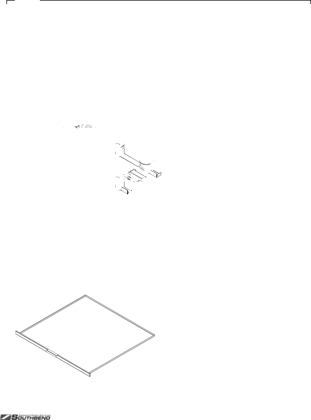
PLATINUM SERIES SECTIONAL RANGE SERVICE
INSTALL AND OPERATIONS MANUAL 1185836 REV 3 (07/06) PAGE 47 OF 80
Fi
g
ure 26
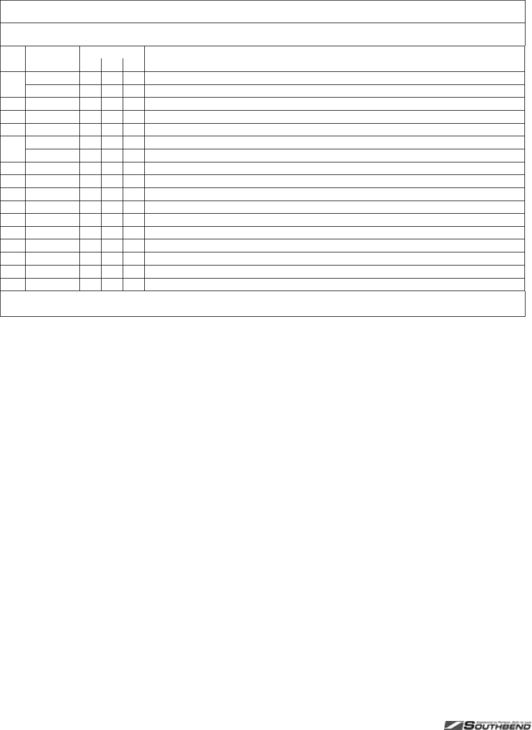
SERVICE PLATINUM SERIES SECTIONAL RANGE
PAGE 48 OF 80 INSTALL & OPERATIONS MANUAL 1185836 REV 3 (07/06)
33K-Open-Burner Gas Train Parts
See drawing on following page.
Quantity*
Key Part Number 12" 32" 48" Description
1 1183923 1 - - MANIFOLD W/A, 2 BURNER OPEN TOP
1185667 - 1 - MANIFOLD W/A,
2 1179222 2 6 8 NIPPLE, EXTENSION
3 1178202 2 6 8 VALVE, HI-OFF, NAT/LP
4 1179188 1 3 4 EXTENSION, ORIFICE
** 1008741 2 6 8 ORIFICE, NAT GAS (if appliance will operate above 2000 ft, contact Southbend for appropriate orifice size)
1008751 2 6 8 ORIFICE, PROPANE (if appliance will operate above 2000 ft, contact Southbend for appropriate orifice size)
5 1182193 2 6 8 BURNER ASSEMBLY, OPEN TOP
** 1182195 1 3 4 FITTING, 1/2" COMP 1/4" NPT (connects rear-burner gas tube to valve)
6 1182192 1 3 4 TUBE, REAR BURNER
7 1182191 1 3 4 ORIFICE FITTING
8 1166004 1 3 4 FITTING, DOUBLE PILOT, 3/16" TUBE
9 1183605 1 3 4 PILOT TUBE W/A REAR
10 1183603 1 3 4 PILOT TUBE W/A FRONT
11 1177106 - 3 - TUBE ASM, REAR BURNER PILOT (for rear pilots of step-up models)
12 1184646 - 2 - TUBE, REAR BURNER STEP-UP (for left rear and center rear burner of step-up models)
13 1184647 - 1 - TUBE, REAR BURNER STEP-UP (for right rear burner of step-up models)
* Quantity of part used may depend on width of section (12", 32", or 48").
** Not shown on drawing.
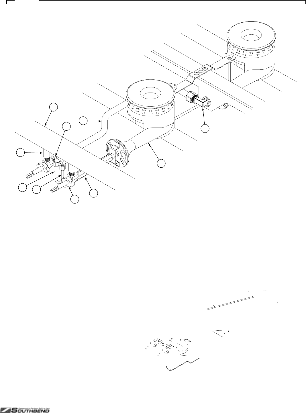
PLATINUM SERIES SECTIONAL RANGE SERVICE
INSTALL AND OPERATIONS MANUAL 1185836 REV 3 (07/06) PAGE 49 OF 80
Fi
g
ure 27
34
1
2
5
67
8
910

SERVICE PLATINUM SERIES SECTIONAL RANGE
PAGE 50 OF 80 INSTALL & OPERATIONS MANUAL 1185836 REV 3 (07/06)
45K-Open-Burner Parts
See drawing on following page.
Quantity*
Key Part Number 16" 32" Description
1 1184689 2 4 KNOB
2 1184762 1 - VALVE PANEL, 16C-X (cabinet base)
1184731 1 - VALVE PANEL, 16N-X (modular-countertop base)
1183562 - 1 VALVE PANEL, 32A/D-XX (oven base)
1183644 - 1 VALVE PANEL, 32C -XX (cabinet base)
1183577 - 1 VALVE PANEL, 32N-XX (modular-countertop base)
3 1183976 1 - TRAY ASSEMBLY, 16" CRUMB
1183970 - 1 TRAY ASSEMBLY, 32" CRUMB
4 1184599 2 - BURNER SUPPORT [16"]
1185562 - 2 BURNER SUPPORT [32"]
5 1179229 1 2 SUPPORT, PILOT
6 1183887 1 - TRIM 36 DEEP 16 FLUE RISER
1183560 - 1 TRIM 36 DEEP 32 FLUE RISER
7 1183899 1 - TRIM 42 DEEP 16 FLUE RISER
1183588 - 1 TRIM 42 DEEP 32 FLUE RISER
8 1179247 1 2 CAST IRON GRATE
9 1185853 1 - MANIFOLD W/A [16"]
1183558 - 1 MANIFOLD W/A [32"]
10 1179222 2 4 NIPPLE, EXTENSION
11 1178202 2 4 VALVE, HI-OFF, NAT/LP
** 1008735 2 4 ORIFICE, NAT GAS (if appliance will operate above 2000 ft, contact Southbend for appropriate orifice size)
1008750 2 4 ORIFICE, PROPANE (if appliance will operate above 2000 ft, contact Southbend for appropriate orifice size)
12 1165742 1 2 VENTURI (for front burners)
13 1165741 1 2 VENTURI (for rear burners)
14 1179230 2 4 BURNER HEAD, 40
15 1177043 2 4 COVER, BURNER DRIP
16 1166004 1 2 FITTING, DOUBLE PILOT, 3/16" TUBE
17 1179246 1 2 PILOT W/A, REAR
18 1179244 1 2 PILOT W/A, FRONT
19 1179240 1 2 BURNER (for front)
1179241 1 2 BURNER (for rear)
* Quantity of part used may depend on width of section (16" or 32").
** Not shown on drawing.
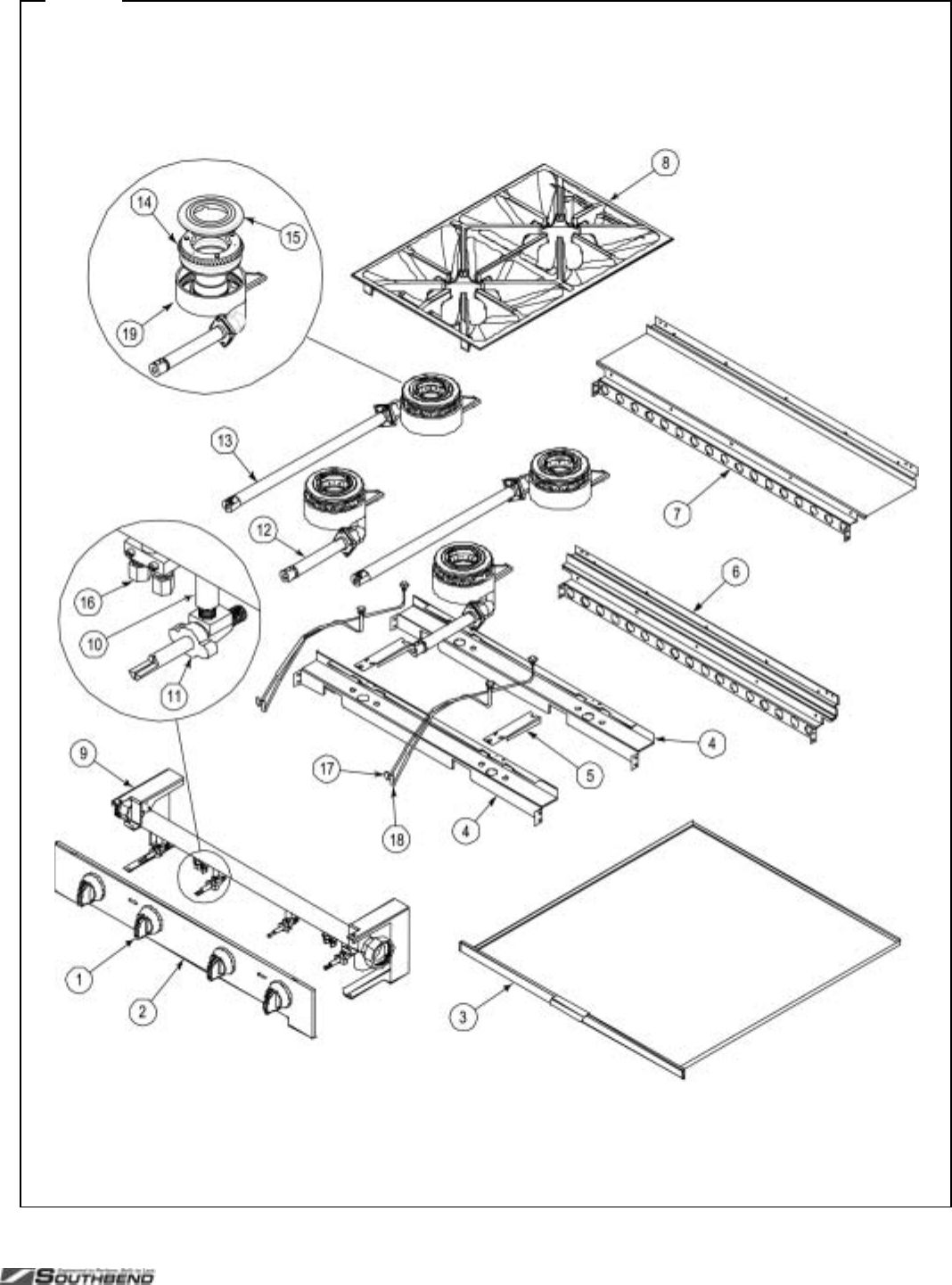
PLATINUM SERIES SECTIONAL RANGE SERVICE
INSTALL AND OPERATIONS MANUAL 1185836 REV 3 (07/06) PAGE 51 OF 80
Fi
g
ure 28
45K-Open-Burner Parts
See parts list on previous page.

SERVICE PLATINUM SERIES SECTIONAL RANGE
PAGE 52 OF 80 INSTALL & OPERATIONS MANUAL 1185836 REV 3 (07/06)
Charbroiler External and Structural Parts for 16" and 32" Models
See drawing on following page.
Quantity*
Key Part Number 16" 32" Description
1 1184689 1 2 KNOB
2 1185945 1 - VALVE PANEL, 16C-C, SS
1185767 1 - VALVE PANEL, 16N-C, SS
1185691 - 1 VALVE PANEL, 32A/D-CC, SS
1185692 - 1 VALVE PANEL, 32C-CC, SS
1185693 - 1 VALVE PANEL, 32N-CC, SS
3 1184773 1 2 COVER, VALVE SHIELD
4 1185564 1 - BRACKET, ORIFICE 16"
1185563 - 1 BRACKET, ORIFICE 32"
5 1185944 1 - SHIELD, 16" VALVE HEAT
1185694 - 1 SHIELD, 32" VALVE HEAT
6 1185646 1 - SHIELD, 16" CHARBROILER HEAT
1185645 - 1 SHIELD, 32" CHARBROILER HEAT
7 1183976 1 - TRAY W/A, 16 CHARBROILER CRUMB
1183970 - TRAY W/A, 32 CHARBROILER CRUMB
8 1185654 1 2 SHIELD, CHAR HEAT DEFLECTOR
9 1185642 1 - SUPPORT, 16" CHAR REAR GRATE
1185648 - 1 SUPPORT, 32 CHAR REAR GRATE
10 1185632 1 - TRIM, CHAR/GRI 16 FLUE RISER
1185631 - 1 TRIM, CHAR/GRI 32 FLUE RISER
** 1185946 1 - TRIM, 42 DEEP CHAR/GRI 16 FLUE RISER
1185671 - 1 TRIM, 42 DEEP CHAR/GRI 32 FLUE RISER
11 1185661 1 - CHARBROILER W/A, 16
1185660 - 1 CHARBROILER W/A, 32
12 1183541 1 1 SHIELD, LEFT DRIP
13 1183542 1 1 SHIELD, RIGHT DRIP
14 1185642 1 - SUPPORT, 16" CHRBRLR GRATE
1185641 - 1 SUPPORT, 32" CHRBRLR GRATE
15 1185640 1 - SHIELD,16" REAR DRIP
1185639 - 1 SHIELD, 32" REAR DRIP
16 1185647 1 2 RADIANT W/A 32
17 1182657 2 5 GRATE, LAVA ROCK
** 1173193 2 5 LAVA ROCK BRIQUETTES, BAG
18 1178976 2 5 CHARBROILER GRID
** 1182838 2 5 PLATED FISH GRID
* Quantity of part used may depend on width of section (16" or 32")
** Not shown on drawing.
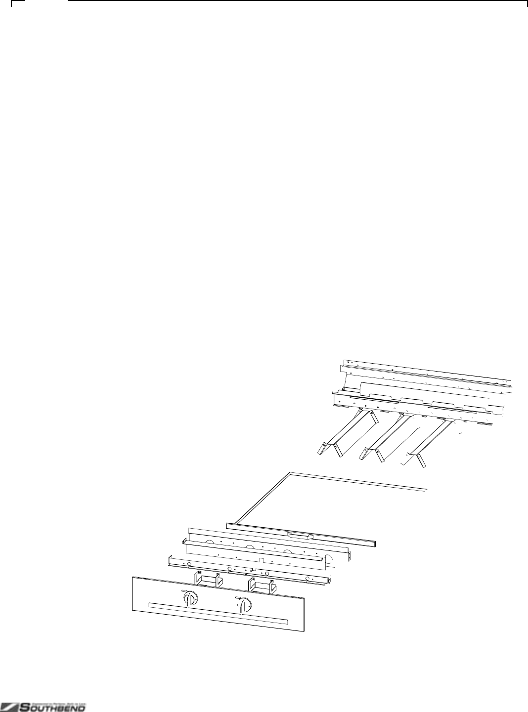
PLATINUM SERIES SECTIONAL RANGE SERVICE
INSTALL AND OPERATIONS MANUAL 1185836 REV 3 (07/06) PAGE 53 OF 80
Fi
g
ure 29

SERVICE PLATINUM SERIES SECTIONAL RANGE
PAGE 54 OF 80 INSTALL & OPERATIONS MANUAL 1185836 REV 3 (07/06)
Charbroiler External and Structural Parts for 24", 36", and 48" Models
See drawing on following page.
Quantity*
Key Part Number 24" 36" 48" Description
1 1184689 2 3 4 KNOB
2 1184519 1 - - VALVE PANEL, 24C-CC, SS
1184521 1 - - VALVE PANEL, 24N-CC, SS
1183641 - 1 - VALVE PANEL, 36A/D-CCC, SS
1183643 - 1 - VALVE PANEL, 36C-CCC, SS
1183642 - 1 - VALVE PANEL, 36N-CCC, SS
1185396 - - 1 VALVE PANEL, 48A/D-CCCC, SS
1185397 - - 1 VALVE PANEL, 48C-CCCC, SS
1185398 - - 1 VALVE PANEL, 48N-CCCC, SS
3 1184773 2 3 4 COVER, VALVE SHIELD
4 1184523 1 - - SHIELD, 24" VALVE HEAT
1184522 - 1 - SHIELD, 36" VALVE HEAT
1185379 - - 1 SHIELD, 48" VALVE HEAT
5 1183896 1 - - BURNER REST, 24 CHAR/GRI
1183524 - 1 - BURNER REST, 36 CHAR/GRI
1183895 - - 1 BURNER REST, 48 CHAR/GRI
6 1183901 1 - - SHIELD, 24" CHARBROILER HEAT
1184543 - 1 - SHIELD, 36" CHARBROILER HEAT
1185388 - - 1 SHIELD, 48" CHARBROILER HEAT
7 1183974 2 - - TRAY W/A, 24 CHARBROILER CRUMB
1184772 - 2 - TRAY W/A, 36 CHARBROILER CRUMB
1185401 - - 1 TRAY W/A, 48 CHARBROILER CRUMB LT
1185486 - - 1 TRAY W/A, 48 CHARBROILER CRUMB RT
8 1184994 2 3 4 BRACKET, RADIANT STOP
9 1183890 1 - - TRIM, CHAR/GRI 24 FLUE RISER
1183635 - 1 - TRIM, CHAR/GRI 36 FLUE RISER
1183889 - - 1 TRIM, CHAR/GRI 48 FLUE RISER
10 1183893 1 - - TRIM, 42 DEEP CHAR/GRI 24 FLUE RISER
1183590 - 1 - TRIM, 42 DEEP CHAR/GRI 36 FLUE RISER
1183892 - - 1 TRIM, 42 DEEP CHAR/GRI 48 FLUE RISER
11 1183541 1 1 1 SHIELD, LEFT DRIP
12 1183542 1 1 1 SHIELD, RIGHT DRIP
13 1183610 1 - - SUPPORT, 24" CHRBRLR GRATE
1183609 - 1 - SUPPORT, 36" CHRBRLR GRATE
1183649 - - 1 SUPPORT, 48" CHRBRLR GRATE
14 1183926 1 - - SHIELD, 24" REAR DRIP
1183525 - 1 - SHIELD, 36" REAR DRIP
1183928 - - 1 SHIELD, 48" REAR DRIP
15 1183786 1 - - CHARBROILER W/A, 24
1183646 - 1 - CHARBROILER W/A, 36
1183789 - - 1 CHARBROILER W/A, 48
16 1183676 2 3 4 RADIANT W/A
17 1182657 4 6 8 GRATE, LAVA ROCK
** 1173193 4 6 8 LAVA ROCK BRIQUETTES, BAG
18 1178976 4 6 8 CHARBROILER GRID
** 1182838 4 6 8 PLATED FISH GRID
* Quantity of part used may depend on width of section (24", 36" or 48")
** Not shown on drawing.

PLATINUM SERIES SECTIONAL RANGE SERVICE
INSTALL AND OPERATIONS MANUAL 1185836 REV 3 (07/06) PAGE 55 OF 80
Fi
g
ure 30

SERVICE PLATINUM SERIES SECTIONAL RANGE
PAGE 56 OF 80 INSTALL & OPERATIONS MANUAL 1185836 REV 3 (07/06)
Wood Smoker External and Structural Parts for 36", 48”, 60” and 72" Models
See drawing on following page.
Key Part Number Qty Description Key Part Number Qty Description
1 1188417 1 Base Assy, 36” Cntrtop Smoker 18 1187100 1 Panel, 36”, 60” Smoker Box Rear
1188416 1 Base Assy, 24” Cntrtop Smoker 1187831 1 Panel, 36”, 60” Smoker Box Rear
1188418 1 Base Assy, 60”, 72” Cntrtop Smoker L. Side 1187962 2 Panel, 72” Smoker Box Rear
1188419 1 Base Assy, 72” Cntrtop Smoker R. Side 19 1186884 2 Bracket, Mounting
1188420 1 Base Assy, 48” Cntrtop Smoker 20 1187954 1 Trim, 60” Smoker Front Center (NOT SHOWN)
2 1187826 2 Bracket, R. Smkr Tie Down 1187815 1 Trim, 72” Smoker Front Center (NOT SHOWN)
31187825 2 Trim, 36”, 48”, 72” inside L & R Smkr Box 21 1188495 1 Hickory Wood Chunks 10lb Bag (NOT
SHOWN)
1187955 2 Trim, 60” Inside L&R Smoker Box 22 1188496 1 Mesquite Wood Chunks 10lb Bag (NOT
SHOWN)
4 11887824 1 Shiled, 36” Heat Diverter 23 1188509 1 Handle, Smoker Door Pull
1187379 2 Shield, 60”, 72” Heat L & R Side 24 1188505 1 Door, 36”, 60” Smoker Box
1187827 1 Shield, 60” Heat Diverter 24” Side 1188506 1 Door, 48” Smoker Box
1187828 1 Shield, 48” Heat Diverter 1188507 1 Door, 72” Smoker Box
5 1187821 1 Valve Panel, P36W-CCC
1187838 1 Valve Panel, P48W-CCCC
1187952 1 Valve Panel, P60W-CCCCC
1188410 1 Valve Panel, P72W-CCCCCC
6 1187819 2 Guide, smoker Drip Pan
7 1187818 1 Grease Drawer Smoker W/A
8 1187814 1 Rack. 36”, 60” Wood Smoker
1187836 1 Rack, 48” Wood Smoker
1187963 2 Rack, 72” Wood Smoker
9 1187813 1 Box W/A, 36”, 60” Smoker
1187832 1 Box W/A, 48” Smoker
1187965 1 Box W/A, 72” Smoker
10 1187807 1 Tray, 36”, 60” Water/Catch
1187837 1 Tray, 48” Water/Catch
1187866 2 Tray, 72” Water/Catch
11 1187373 1 Burner Box Bottom, 36” Smoker
1187111 1 Burner Box Bottom, 48” Smoker
1187843 1 Burner Box Bottom, 60”, 72 Smoker 36” Left Side
1188402 1 Burner Box Bottom, 72” Smoker 36” Right Side
12 1187372 1 PL/36 Platinum Stand
1187823 1 PL/48 Platinum Stand
1188421 1 PL/60 Platinum Stand
1188422 1 PL/72 Platinum Stand
13 1187370 1 Trim, 36” Smoker Opening Finish
1187361 1 Trim, 48” Smoker Opening Finish
1187378 1 Trim, 36”, 72” Smoker Opening Finish
1187371 1 Trim, 60” Smoker 24” Side Opening Finish
1188404 1 Trim, 72” Smoker 36” R. SideOpening Finish
14 1187368 1 Trim, 36” Smoker Rear Body
1187369 1 Trim, 48” Smoker Rear Body
1187956 1 Trim, 60” Smoker Rear Body
1187816 2 Trim, 72” Smoker Rear Body
15 1187367 2 Side, 35”, 48”, 72” Smoker L & R Body
1187953 2 Side, 60” Smoker L & R Body
16 1187113 1 Diverter, 36” R Smoker Grease
1187114 1 Diverter, 48” R Smoker Grease
1187849 1 Diverter, 60”, 72” Smoker 36” L. Side
1187377 1 Diverter, 60” Smoker 24” R. Side
1188403 1 Diverter, 72” Smoker 36” R. Side
17 1187112 2 Grease Catch, LT & RT

PLATINUM SERIES SECTIONAL RANGE SERVICE
INSTALL AND OPERATIONS MANUAL 1185836 REV 3 (07/06) PAGE 57 OF 80
Fi
g
ure 31

SERVICE PLATINUM SERIES SECTIONAL RANGE
PAGE 58 OF 80 INSTALL & OPERATIONS MANUAL 1185836 REV 3 (07/06)
Fi
g
ure 32
Charbroiler and Standard-Griddle Gas Train Parts
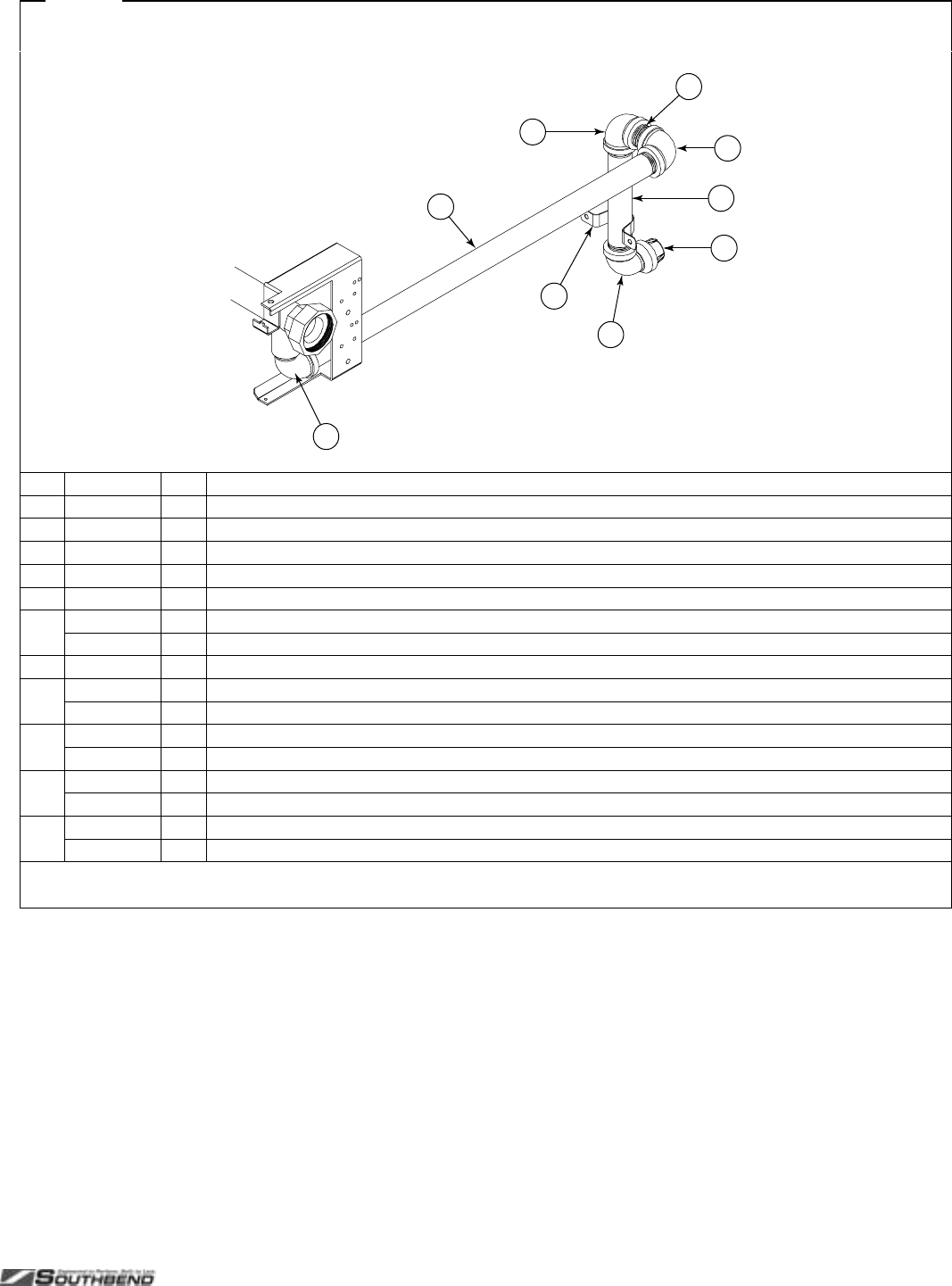
PLATINUM SERIES SECTIONAL RANGE SERVICE
INSTALL AND OPERATIONS MANUAL 1185836 REV 3 (07/06) PAGE 59 OF 80
Fi
g
ure 33
Gas Connection Parts
3
4
1
2
5
6
7
2
2
Key Part Number Qty Description
1 1147005 1 1" PIPE CAP
2 1146905 2 1" 90 DEGREE ELBOW
3 1163489 1 REAR GAS STUB
4 1184777 1 STRAP, 1-1/4" PIPE
5 1146808 1 1" PIPE NIPPLE
6 1174747 1 TAIL PIPE
1185827 1 TAIL PIPE FOR BBB MODELS
7 1146911 1 ELBOW, ST., BLK, 1" 90 DEGREE
** 4450009 * PRESSURE REGULATOR 1-1/4" 2,500,000 BTU NAT
4450010 * PRESSURE REGULATOR 1-1/4" 2,500,000 BTU LP
** 1167782 * PRESSURE REGULATOR 1" 600,000 BTU NAT
1167783 * PRESSURE REGULATOR 1" 600,000 BTU LP
** 4450008 * 1-1/4" GAS SHUT OFF VALVE
4450007 * 1" GAS SHUT OFF VALVE
** 1130195 * 1" QUICK DISCONNECT, 48" FLEX HOSE
1130194 * 1" QUICK DISCONNECT, 60" FLEX HOSE
* Quantity varies.
** Not shown on drawing.

SERVICE PLATINUM SERIES SECTIONAL RANGE
PAGE 60 OF 80 INSTALL & OPERATIONS MANUAL 1185836 REV 3 (07/06)
Griddle External and Structural Parts
See drawing on following page.
Quantity*
Key Part Number 16" 32" 48" Description
1 1073497 1 2 3 KNOB [for thermostatic griddles]
1184689 1 2 3 KNOB [for standard, non-thermostatic griddles]
2 1182156 1 2 3 KNOB ASM, VALVE
3 1185952 1 - - VALVE PANEL, 16C-G, SS
1185953 1 - - VALVE PANEL, 16C-T, SS
1185954 1 - - VALVE PANEL, 16N-G, SS
1185955 1 - - VALVE PANEL, 16N-T, SS
1185918 - 1 - VALVE PANEL, 32A/D-GG, SS
1185664 - 1 - VALVE PANEL, 32A/D-TT, SS
1185920 - 1 - VALVE PANEL, 32C-GG, SS
1185665 - 1 - VALVE PANEL, 32C-TT, SS
1185919 - 1 - VALVE PANEL, 32N-GG, SS
1185666 - 1 - VALVE PANEL, 32N-TT, SS
1184680 - - 1 VALVE PANEL, 48A/D-GGG, SS
1184674 - - 1 VALVE PANEL, 48A/D-TTT, SS
1184682 - - 1 VALVE PANEL, 48C-GGG, SS
1184676 - - 1 VALVE PANEL, 48C-TTT, SS
1184684 - - 1 VALVE PANEL, 48N-GGG, SS
1184678 - - 1 VALVE PANEL, 48N-TTT, SS
4 1183696 1 1 1 GREASE DRAWER W/A
5 1183691 1 1 1 GREASE DRAWER BASE W/A
6 1184773 1 2 3 COVER, VALVE SHIELD
7 1185564 2 - - BURNER REST, 16 CHAR/GRI
1185563 - 2 - BURNER REST, 32 CHAR/GRI
1183895 - - 2 BURNER REST, 48 CHAR/GRI
8 1185912 1 - - SHIELD, 16" GRIDDLE HEAT
1185589 - 1 - SHIELD, 32" GRIDDLE HEAT
1185387 - - 1 SHIELD, 48" GRIDDLE HEAT
9 1183685 - 1 2 BURNER BOX DIVIDER
10 1185632 1 - - TRIM, CHAR/GRI 16 FLUE RISER
1185631 - 1 - TRIM, CHAR/GRI 32 FLUE RISER
1183889 - - 1 TRIM, CHAR/GRI 48 FLUE RISER
11 1185946 1 - - TRIM, 42 DEEP CHAR/GRI 16 FLUE RISER
1185671 - 1 - TRIM, 42 DEEP CHAR/GRI 32 FLUE RISER
1183892 - - 1 TRIM, 42 DEEP CHAR/GRI 48 FLUE RISER
12 1146383 1 2 3 BOLT, HEX, 5/16-18X5LG. (thermostatic griddles only)
13 1183692 1 2 3 SHIELD, T'STAT BULB (thermostatic griddles only)
14 501601-B 1 - - GRIDDLE W/A, 16 STANDARD
1185698 - 1 - GRIDDLE W/A, 32 STANDARD
1185378 - - 1 GRIDDLE W/A, 48 STANDARD
1185887 1 - - GRIDDLE W/A, 16 T-STAT
1185656 - 1 - GRIDDLE W/A, 32 T-STAT
1185464 - - 1 GRIDDLE W/A, 48 T-STAT
* Quantity of part used may depend on width of section (16", 32", or 48").
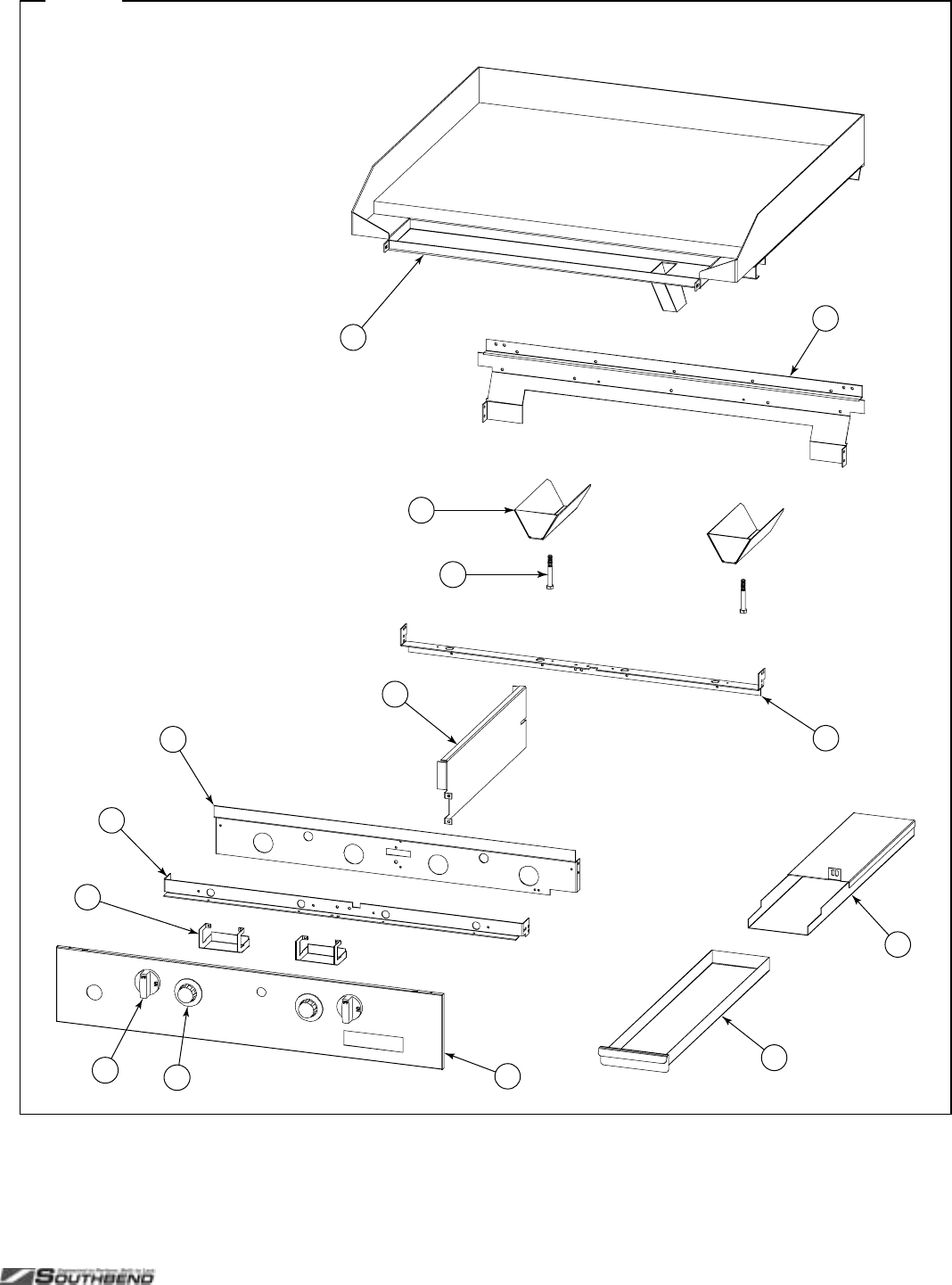
PLATINUM SERIES SECTIONAL RANGE SERVICE
INSTALL AND OPERATIONS MANUAL 1185836 REV 3 (07/06) PAGE 61 OF 80
Fi
g
ure 34
34
12
5
7
8
9
7
13
14
12
11
6
Griddle External and Structural Parts
See parts list on previous page.

SERVICE PLATINUM SERIES SECTIONAL RANGE
PAGE 62 OF 80 INSTALL & OPERATIONS MANUAL 1185836 REV 3 (07/06)
Thermostatic Griddle Gas Train Parts
See drawing on following page.
Quantity*
Key Part Number 16" 32" 48" Description
1 1185762 1 - 1 MANIFOLD W/A, 16, CHAR/GRI SECT
1185761 - 1 1 MANIFOLD W/A, 32, CHAR/GRI SECT
2 1185596 1 - 1 SUPPORT, 16 THERMOSTAT
1185570 - 1 1 SUPPORT, 32 THERMOSTAT
3 1183549 1 1 2 VALVE, 200K BURNER
4 1185539 1 1 2 TUBE, SAFETY VALVE
5 1185537 1 1 2 SAFETY VALVE SINGLE
6 1185538 1 1 2 MANIFOLD BOX
7 1160008 1 2 3 ELBOW, BRASS
8 1185594 1 1 2 TUBE, LEFT ON/OFF GAS
9 1185595 - 1 1 TUBE, RIGHT ON/OFF GAS
10 1182553 1 2 3 SNAP ACTION GRIDDLE THERMOSTAT
11 1183503 1 2 3 TUBE, 3/8" X 9" FLEXIBLE
12 1185503 1 2 3 MANIFOLD, DUAL BURNER ORIFICE
** 1008748 2 4 6 ORIFICE, NAT GAS (if appliance will operate above 2000 ft, contact Southbend for appropriate orifice size)
1008756 2 4 6 ORIFICE, PROPANE (if appliance will operate above 2000 ft, contact Southbend for appropriate orifice size)
13 1182762 2 4 6 BURNER ASSEMBLY, CHARBROILER
14 1185675 1 1 2 TUBE, T-GRID LT PILOT ADJUST
15 1164085 1 1 2 VALVE ASM, PILOT
16 1185829 1 1 2 TUBE, T-GRID RT PILOT ADJUST
17 1183687 1 1 2 ASSEMBLY, PILOT SHIELD
18 1183681 1 1 2 BRACKET, PILOT
19 1182580 1 1 2 THERMOCOUPLE, 24 IN
20 1183573 1 2 3 TUBE, RUNNER TUBE ORIFICE
21 1183584 1 2 3 FITTING, NAT 3/8 REDUCER
22 1183536 1 2 3 TUBE ASSEMBLY, PILOT RUNNER
* Quantity of part used may depend on width of section (16", 32", or 48").
** Not shown on drawing.
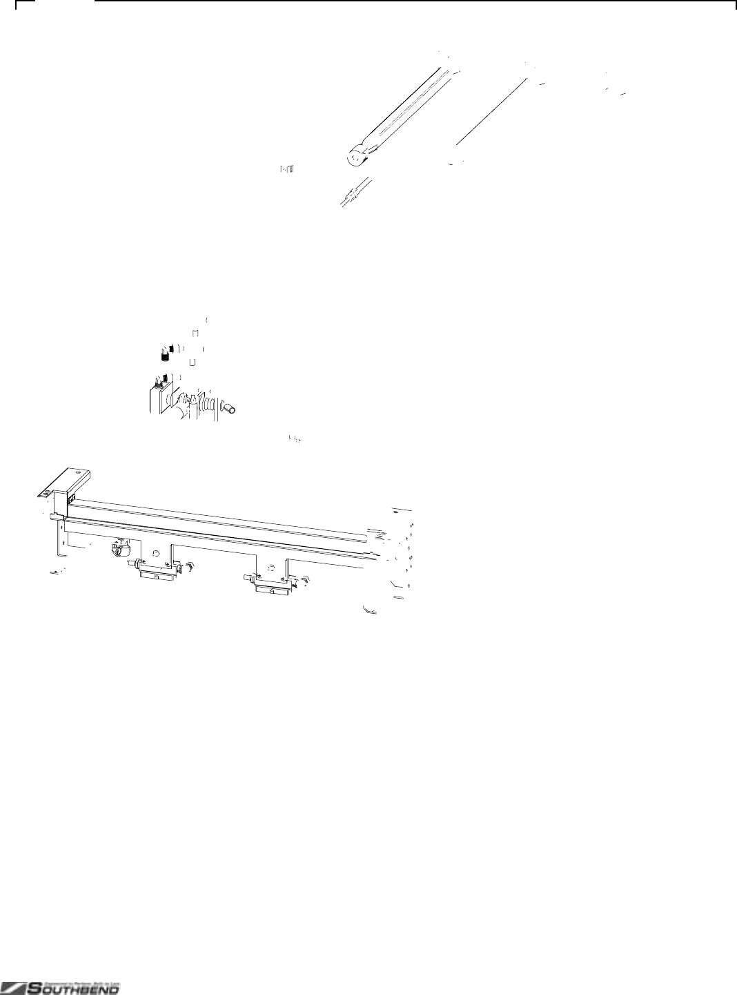
PLATINUM SERIES SECTIONAL RANGE SERVICE
INSTALL AND OPERATIONS MANUAL 1185836 REV 3 (07/06) PAGE 63 OF 80
Fi
g
ure 35

SERVICE PLATINUM SERIES SECTIONAL RANGE
PAGE 64 OF 80 INSTALL & OPERATIONS MANUAL 1185836 REV 3 (07/06)
Uniform Hot-Top Parts
See drawing on following page.
Quantity*
Key Part Number 16" 32" Description
1 1184689 1 2 KNOB
2 1185766 1 - VALVE PANEL, 16C-H, SS
1185951 1 - VALVE PANEL, 16N-H, SS
1185758 - 1 VALVE PANEL, 32A/D-HH, SS
1185759 - 1 VALVE PANEL, 32C-HH, SS
1185760 - 1 VALVE PANEL, 32N-HH, SS
3 1185564 2 4 BRACKET, ORIFICE 16"
4 1184551 - 1 COVER, BATTERY CENTER
5 1183506 1 2 BURNER BOX BOTTOM, 16
6 1183563 - 1 TRIM, CENTER
7 1184545 - 1 COVER, HOT TOP DIVIDER REAR
8 1185739 1 2 SHIELD, 32 HOT TOP HEAT
9 1185826 1 2 BAFFLE, 16" HOT TOP
10 1183887 1 - TRIM, HOT TOP 16 FLUE RISER
1185737 - 1 TRIM, HOT TOP 32 FLUE RISER
** 1183899 1 - TRIM, HOT TOP 42 DEEP 16 FLUE RISER
1185738 - 1 TRIM, HOT TOP 42 DEEP 32 FLUE RISER
11 1019601 1 2 PLATE, UNIFORM HEATED TOP
12 1185763 1 - MANIFOLD ASM, 16 UNIFORM H/TOP
1185736 - - MANIFOLD ASM, 32 UNIFORM H/TOP
13 1179222 1 2 NIPPLE, EXTENSION
14 1176008 1 2 VALVE, BURNER, NAT
15 1183503 1 2 TUBE, 3/8" X 9" FLEXIBLE
16 1185503 1 2 MANIFOLD, 32" DUAL BURNER ORIFICE
** 1008750 2 4 ORIFICE, NAT GAS (if appliance will operate above 2000 ft, contact Southbend for appropriate orifice size)
1008756 2 4 ORIFICE, PROPANE (if appliance will operate above 2000 ft, contact Southbend for appropriate orifice size)
17 1182762 2 4 BURNER ASSEMBLY, CHARBROILER
18 1166004 1 2 FITTING, DOUBLE PILOT, 3/16" TUBE
19 1185741 1 2 TUBE W/A, CHAR. LEFT PILOT
20 1185743 1 2 TUBE W/A, CHAR. RIGHT PILOT
21 1182821 2 4 BRACKET, PILOT
* Quantity of part used may depend on width of section (16" or 32").
** Not shown on drawing.
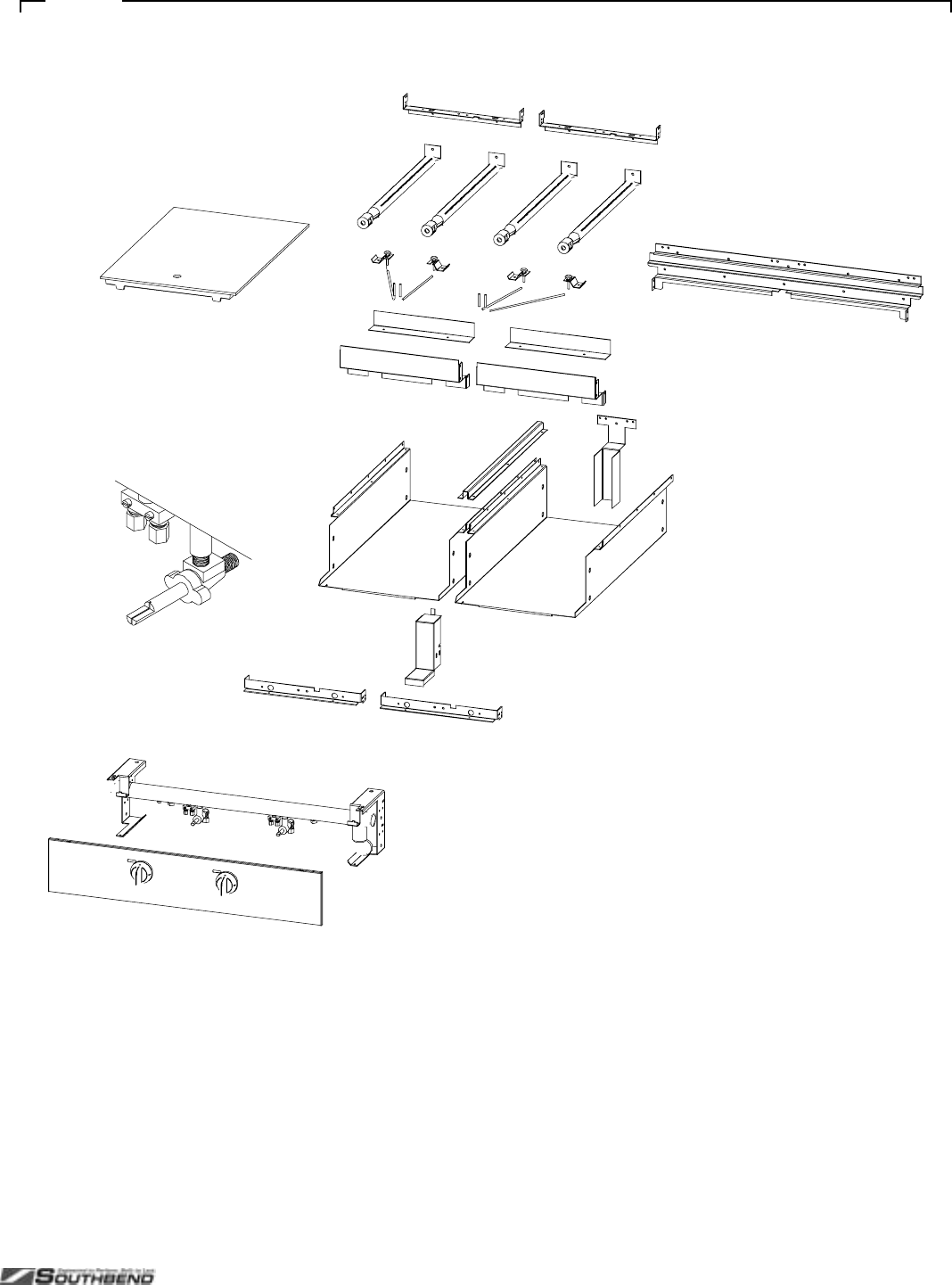
PLATINUM SERIES SECTIONAL RANGE SERVICE
INSTALL AND OPERATIONS MANUAL 1185836 REV 3 (07/06) PAGE 65 OF 80
Fi
g
ure 36

SERVICE PLATINUM SERIES SECTIONAL RANGE
PAGE 66 OF 80 INSTALL & OPERATIONS MANUAL 1185836 REV 3 (07/06)
Graduated-Hot-Top Parts
See drawing on following page.
Key Part Number Qty Description
1 1184689 1 KNOB
2 1185940 1 VALVE PANEL, 32A/D-GRAD, SS (oven base)
1185942 1 VALVE PANEL, 32C-GRAD, SS (cabinet base)
1185941 1 VALVE PANEL, 32N-GRAD, SS (modular-countertop base)
3 1183560 1 TRIM, 32 FLUE RISER
4 1183588 1 TRIM, 42 DEEP 32 FLUE RISER
5 1185659 2 BURNER REST, GRADUATED
6 1183959 2 BRACKET, BURNER HOLD DOWN
7 1185658 1 SHIELD, GRADUATED BURNER
8 1018998 2 PLATE, GRADUATED HEAT TOP
9 1018997 1 PS, GRIDDLE, CSTIR, RING, GRAD.
10 1018996 1 PS, GRIDDLE, CSTIR, LID.GRAD.
11 1185943 1 MANIFOLD W/A, GRADUATED H/TOP
12 1176016 1 BURNER VALVE, NAT
* 1006425 1 ORIFICE, NAT GAS (if appliance will operate above 2000 ft, contact Southbend for appropriate orifice size)
1006443 1 ORIFICE, PROPANE (if appliance will operate above 2000 ft, contact Southbend for appropriate orifice size)
13 1884 1 HOT TOP BRNR ASM
14 1160293 1 BAFFLE, TOP BURNER AIR
15 1099002 1 PILOT ADJUST
16 1164199 1 TUBE, PILOT
17 1183964 1 BRACKET, PILOT ASSEMBLY
18 1038099 1 ASSEMBLY, PILOT
* Not shown on drawing.
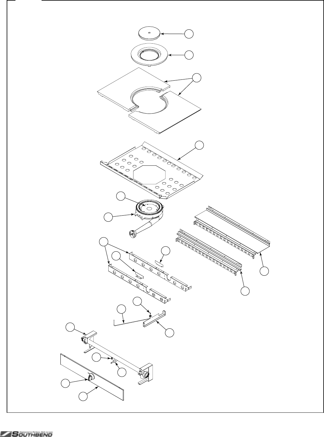
PLATINUM SERIES SECTIONAL RANGE SERVICE
INSTALL AND OPERATIONS MANUAL 1185836 REV 3 (07/06) PAGE 67 OF 80
Fi
g
ure 37
1
2
4
3
66
18
7
9
10
11
12
14
15
13
16
17
5
8
Graduated-Hot-Top Parts
See parts list on previous page.

SERVICE PLATINUM SERIES SECTIONAL RANGE
PAGE 68 OF 80 INSTALL & OPERATIONS MANUAL 1185836 REV 3 (07/06)
Oven Base Parts
See drawing on following page.
Key Part Number Qt
yDescription
1 1180776 1 OVEN BOTTOM\FLAME
2 1180528 2 RACK_GUIDE CO BASE
3 6660 8 CLIP, RACK SUPPORT
* 1173545CP 1 OVEN RACK (for standard oven)
1179920 1 OVEN RACK (for convection oven)
4 1177541 1 POWER SWITCH
5 1177790 1 ON/OFF FAN SWITCH (for convection oven)
6 1176650 1 LIGHT
7 1174749 1 KNOB
* 1173542 1 THERMOSTAT
8 1184622 1 CONTROL PANEL W/A
9 1184102 1 ASSEMBLY, OVEN DOOR
* 1180861 2 DOOR HINGE ASSEMBLY
* 1183575 1 KICK PANEL
10 1184998
1173759 1
1OVEN DOOR SPRING
OVEN DOOR SPRING (effective 2/20/04)
11 1183551 1 BRACKET ASSEMBLY, ROLLER ASM
12 1177567 1 DOOR SWITCH
13 1183619 1 DOOR SWITCH BRACKET
14 1168262 1 SWITCH, FLAME
15 1165708 1 FLM SW MNT BRKT
16 1164809 1 SPARK MODULE
* 1184997 1 SPARK MODULE SHIELD
17 1183518 1 KNOB, ON/OFF
18 1176099 1 VALVE, BURNER
19 1006299 1 ELBOW, 1/2CC X 3/8M F
20 1184417 1 TUBE, OVEN GAS SUPPLY
21 1185533 1 SOLENOID VALVE ASM, 120V/60
22 1183633 1 SOLENOID TO ORIFICE TUBE
23 1183568 1 BRACKET, ORIFICE
* 1008730 1 ORIFICE, NAT GAS (if appliance will operate above 2000 ft, contact Southbend for appropriate orifice size)
1008748 1 ORIFICE, PROPANE (if appliance will operate above 2000 ft, contact Southbend for appropriate orifice size)
24 1165733 1 BURNER
25 1182072 1 BRACKET, OVEN BURNER
26 1185851 1 PILOT TUBE (effective as of 5/1/03)
27 1168263 1 PILOT
28 1164807 1 ELECTRODE
29 1183504 1 PILOT SHIELD BRACKET
30 1165783 1 DOOR SPROCKET BUSHING
31 1166129 1 DOOR CHAIN PULLEY
32 1179710 1 BLOWER MOTOR SPACER
33 1183574 1 1/8” DIA X 1” COTTER PIN ZINC
34 1183618 1 PULLEY BRACKET
35 1183683 1 DOOR PULLEY PIN
* Not shown on drawing.
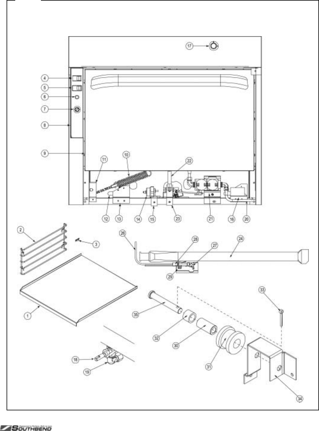
PLATINUM SERIES SECTIONAL RANGE SERVICE
INSTALL AND OPERATIONS MANUAL 1185836 REV 3 (07/06) PAGE 69 OF 80
Fi
g
ure 38
Oven Base Parts
See parts list on previous page.
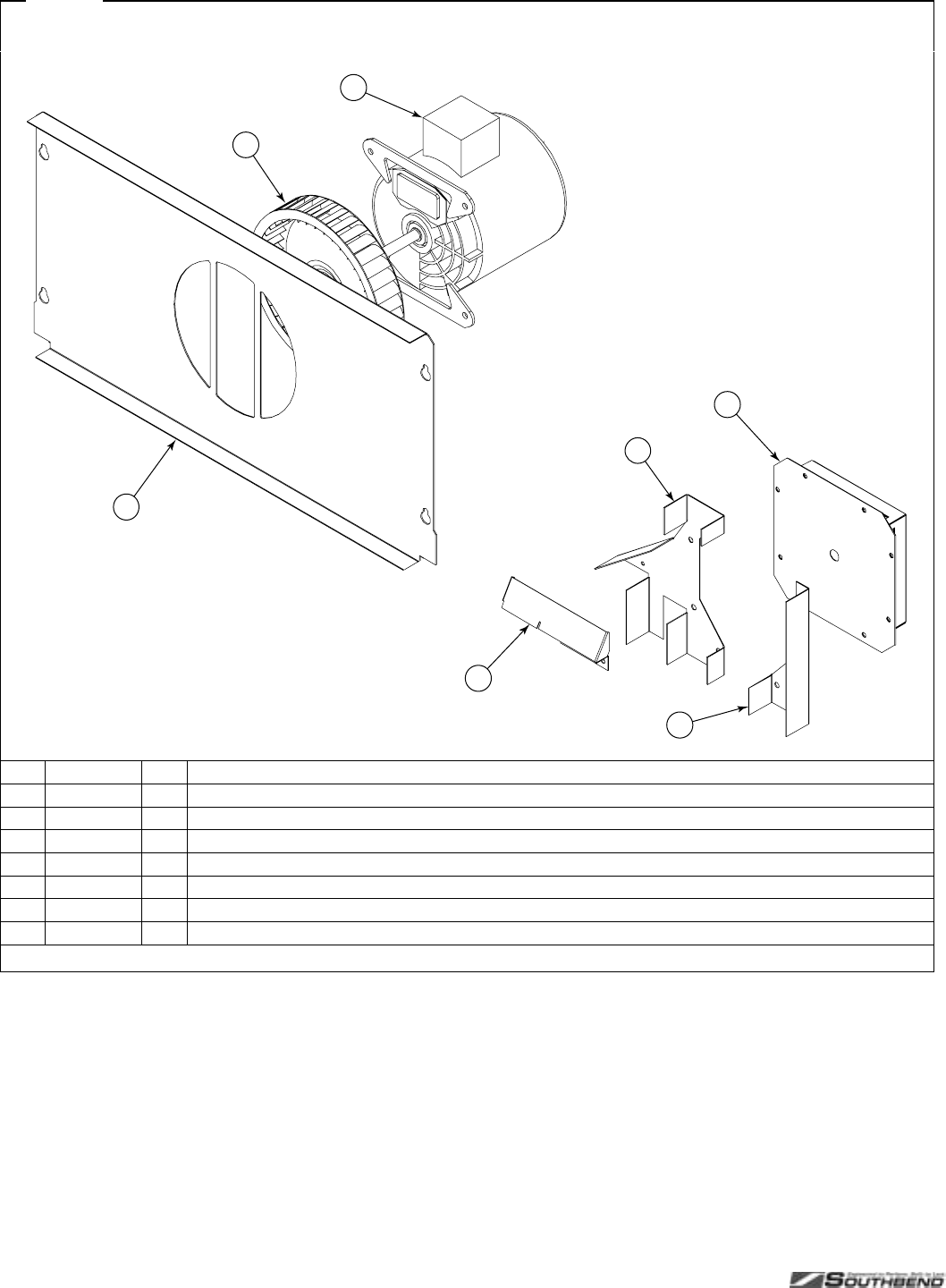
SERVICE PLATINUM SERIES SECTIONAL RANGE
PAGE 70 OF 80 INSTALL & OPERATIONS MANUAL 1185836 REV 3 (07/06)
Fi
g
ure 39
Convection Oven Blower Parts
3
4
1
2
5
6
7
Key Part Number Qty Description
1 1180834 1 OVEN BAFFLE CO
2 1177581 1 BLOWER WHEEL ASSEMBLY
3 1177452 1 MOTOR, 1/3 HP, 115 VOLT
4 1180821 1 POCKET W/A, BLOWER, 500 SERIES
5 1181747 1 SHIELD, RT BLOWER, 500 SERIES
6 1181748 1 SHIELD, LT BLOWER, 500 SERIES
7 1184703 1 AIR DIVERTER
* Not shown on drawing.
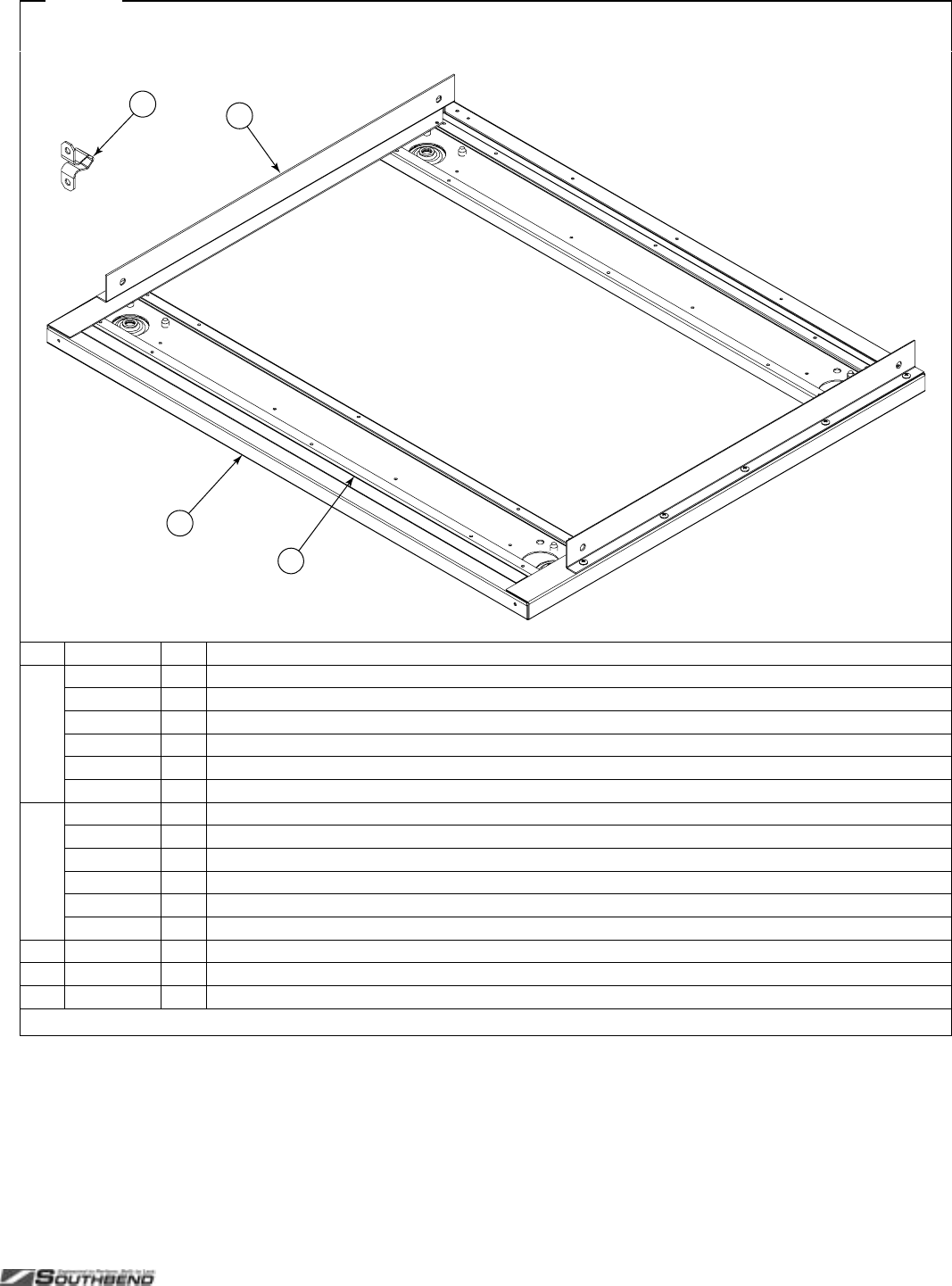
PLATINUM SERIES SECTIONAL RANGE SERVICE
INSTALL AND OPERATIONS MANUAL 1185836 REV 3 (07/06) PAGE 71 OF 80
Fi
g
ure 40
Modular-Countertop Base Parts
3
4
1
2
Key Part Number Qty Description
1 1183863 1 BASE. 12 COUNTERTOP
1183862 1 BASE. 16 COUNTERTOP
1183859 1 BASE. 24 COUNTERTOP
1183576 1 BASE. 32 COUNTERTOP
1183523 1 BASE. 36 COUNTERTOP
1185418 1 BASE. 48 COUNTERTOP
2 1183861 2 STIFFENER, 12 BASE
1183860 2 STIFFENER, 16 BASE
1183858 2 STIFFENER, 24 BASE
1183580 2 STIFFENER, 32 BASE
1183579 2 STIFFENER, 36 BASE
1185413 2 STIFFENER, 48 BASE
3 1183640 2 RETAINER, MODULAR TOP
4 1164132 2 STRIKER (for valve panel)
* 1164133 2 CATCH (for valve panel)
* Not shown on drawing.

SERVICE PLATINUM SERIES SECTIONAL RANGE
PAGE 72 OF 80 INSTALL & OPERATIONS MANUAL 1185836 REV 3 (07/06)
Cabinet-Base Parts
See drawing on following page.
Quantity*
Key Part Number 12" 16" 24" 32" 36" 48" Description
1 1184954 1 -----
CABINET LINING ASM, 12" LT FT
1185496 - 1 ----
CABINET LINING ASM, 16" LT FT
1184952 - - 1 - - 2 CABINET LINING ASM, 24" LT FT
1183595 - - - 1 - - CABINET LINING ASM, 32" LT FT
1183598 ----1-
CABINET LINING ASM, 36" LT FT
2 1184955 1 -----
CABINET LINING ASM, 12" RT FT
1185497 - 1 ----
CABINET LINING ASM, 16" RT FT
1184953 - - 1 - - 2 CABINET LINING ASM, 24" RT FT
1183596 - - - 1 - - CABINET LINING ASM, 32" RT FT
1183599 ----1-
CABINET LINING ASM, 36" RT FT
3 1183875 1 -----
CABINET LINING, 12" BOTTOM
1183874 - 1 ----
CABINET LINING, 16" BOTTOM
1183873 - - 1 - - 2 CABINET LINING, 24" BOTTOM
1183600 ----1-
CABINET LINING, 32"-36" BOTTOM
4 1183563 - - - 1 1 - TRIM, CENTER
5 1183866 1 -----
CABINET LINING, 12" LEFT
1183865 - 1 ----
CABINET LINING, 16" LEFT
1183864 - - 1 - - 2 CABINET LINING, 24" LEFT
1183586 ----1-
CABINET LINING, 32"-36" LEFT
6 1183869 1 -----
CABINET LINING, 12" RIGHT
1183868 - 1 ----
CABINET LINING, 16" RIGHT
1183867 - - 1 - - 2 CABINET LINING, 24" RIGHT
1183587 ----1-
CABINET LINING, 32"-36" RIGHT
7 1183872 1 -----
CABINET LINING, 12" BACK
1183871 - 1 ----
CABINET LINING, 16" BACK
1183870 - - 1 - - 2 CABINET LINING, 24" BACK
1183594 ----1-
CABINET LINING, 32"-36" BACK
** 1183983 - 11112
HINGE ASSEMBLY, UPPER RIGHT
** 1183984 - 11112
HINGE ASSEMBLY, LOWER RIGHT
** 1183985 111112
HINGE ASSEMBLY, UPPER LEFT
** 1183986 111112
HINGE ASSEMBLY, LOWER LEFT
* Quantity of part used may depend on width of section (12", 16", 24", 32", 36", or 48").
** Not shown on drawing.
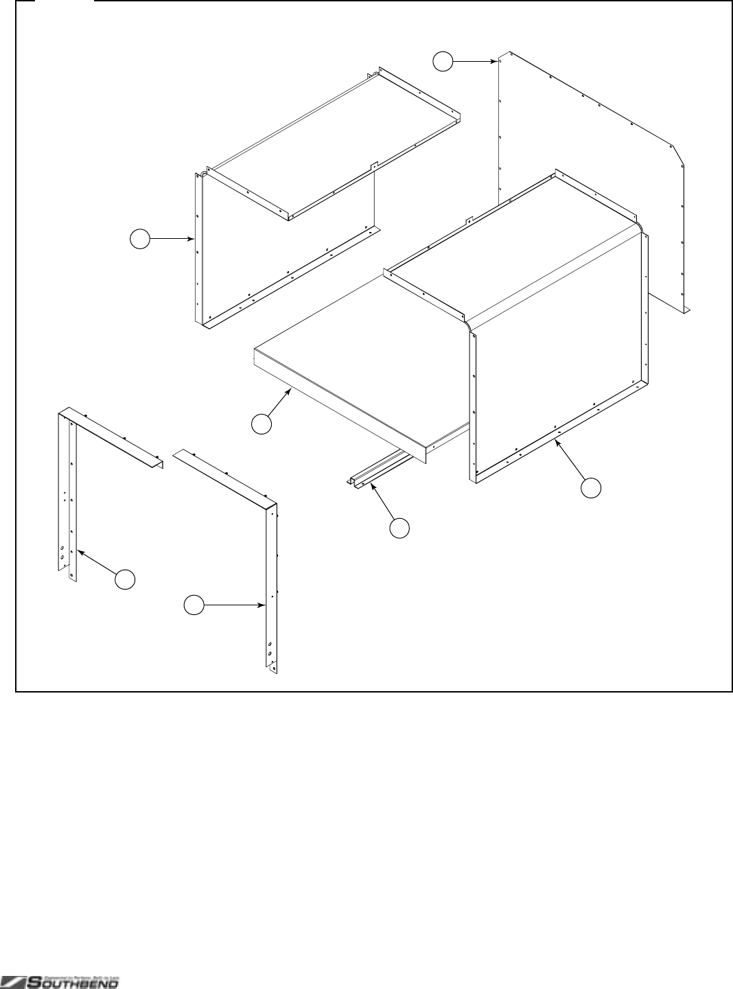
PLATINUM SERIES SECTIONAL RANGE SERVICE
INSTALL AND OPERATIONS MANUAL 1185836 REV 3 (07/06) PAGE 73 OF 80
Fi
g
ure 41
3
4
1
2
5
6
7
Cabinet-Base Parts
See parts list on previous page.

SERVICE PLATINUM SERIES SECTIONAL RANGE
PAGE 74 OF 80 INSTALL & OPERATIONS MANUAL 1185836 REV 3 (07/06)
Flue Riser Parts
See drawing on following page.
For continuous flue risers spanning multiple sections, or sloped enclosures, contact Southbend.
Key Part Number Qty Description
1 1183617 1 FLUE BOX ASSEMBLY (for models with an oven base)
2 1183526 1 BRACKET, 36 DEEP LT FLUE RISER
1183527 1 BRACKET, 36 DEEP RT FLUE RISER
3 1183528 1 BRACKET, 42 DEEP LT FLUE RISER
1183529 1 BRACKET, 42 DEEP RT FLUE RISER
4 1183791 1 SPLASHER, 5" X 12" [height x width]
1183792 1 SPLASHER, 5" X 16"
1183793 1 SPLASHER, 5" X 24"
1183794 1 SPLASHER, 5" X 32"
1183530 1 SPLASHER, 5" X 36"
1183795 1 SPLASHER, 5" X 48"
1183801 1 SPLASHER, 24" X 12"
1183802 1 SPLASHER, 24" X 16"
1183803 1 SPLASHER, 24" X 24"
1183804 1 SPLASHER, 24" X 32"
1183851 1 SPLASHER, 24" X 36"
1183805 1 SPLASHER, 24" X 48"
1183811 1 SPLASHER, 36" X 12"
1183812 1 SPLASHER, 36" X 16"
1183813 1 SPLASHER, 36" X 24"
1183814 1 SPLASHER, 36" X 32"
1183852 1 SPLASHER, 36" X 36"
1183815 1 SPLASHER, 36" X 48"
5 1183821 1 SHIELD, 5" X 12" WALL AZ
1184785 1 SHIELD, 5" X 12" WALL SS
1183822 1 SHIELD, 5" X 16" WALL AZ
1185860 1 SHIELD, 5" X 16" WALL SS
1183823 1 SHIELD, 5" X 24" WALL AZ
1184786 1 SHIELD, 5" X 24" WALL SS
1183824 1 SHIELD, 5" X 32" WALL AZ
1185859 1 SHIELD, 5" X 32" WALL SS
1183684 1 SHIELD, 5" X 36" WALL AZ
1184791 1 SHIELD, 5" X 36" WALL SS
1183825 1 SHIELD, 5" X 48" WALL AZ
1184792 1 SHIELD, 5" X 48" WALL SS
1183831 1 SHIELD, 24" X 12" WALL AZ
1184793 1 SHIELD, 24" X 12" WALL SS
1183832 1 SHIELD, 24" X 16" WALL AZ
1185862 1 SHIELD, 24" X 16" WALL SS
1183833 1 SHIELD, 24" X 24" WALL AZ
1184794 1 SHIELD, 24" X 24" WALL SS
1183834 1 SHIELD, 24" X 32" WALL AZ
1185861 1 SHIELD, 24" X 32" WALL SS
1183853 1 SHIELD, 24" X 36" WALL AZ
1184795 1 SHIELD, 24" X 36" WALL SS
1183835 1 SHIELD, 24" X 48" WALL AZ
1184796 1 SHIELD, 24" X 48" WALL SS
Table continues on next page.
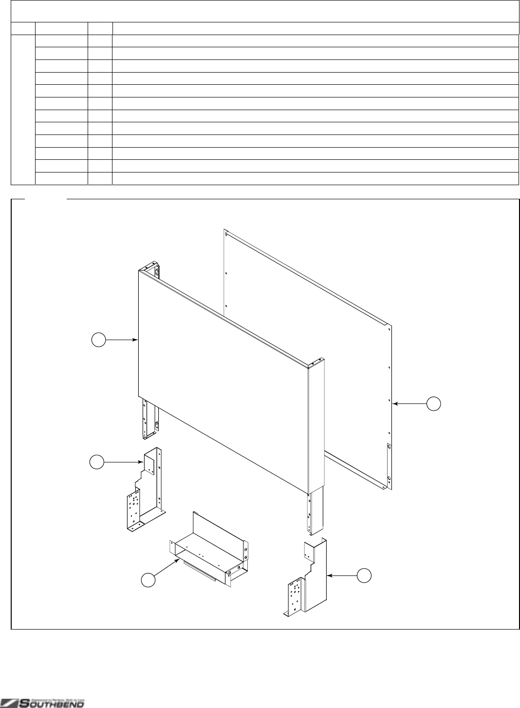
PLATINUM SERIES SECTIONAL RANGE SERVICE
INSTALL AND OPERATIONS MANUAL 1185836 REV 3 (07/06) PAGE 75 OF 80
Flue Riser Parts (continued)
Key Part Number Qty Description
5 1183841 1 SHIELD, 36" X 12" WALL AZ
1184797 1 SHIELD, 36" X 12" WALL SS
1183842 1 SHIELD, 36" X 16" WALL AZ
1185864 1 SHIELD, 36" X 16" WALL SS
1183843 1 SHIELD, 36" X 24" WALL AZ
1184798 1 SHIELD, 36" X 24" WALL SS
1183844 1 SHIELD, 36" X 32" WALL AZ
1185863 1 SHIELD, 36" X 32" WALL SS
1183854 1 SHIELD, 36" X 36" WALL AZ
1184799 1 SHIELD, 36" X 36" WALL SS
1183845 1 SHIELD, 36" X 48" WALL AZ
1184900 1 SHIELD, 36" X 48" WALL SS
Fi
g
ure 42
3
4
12
5
Flue Riser Parts
See parts list on previous page.
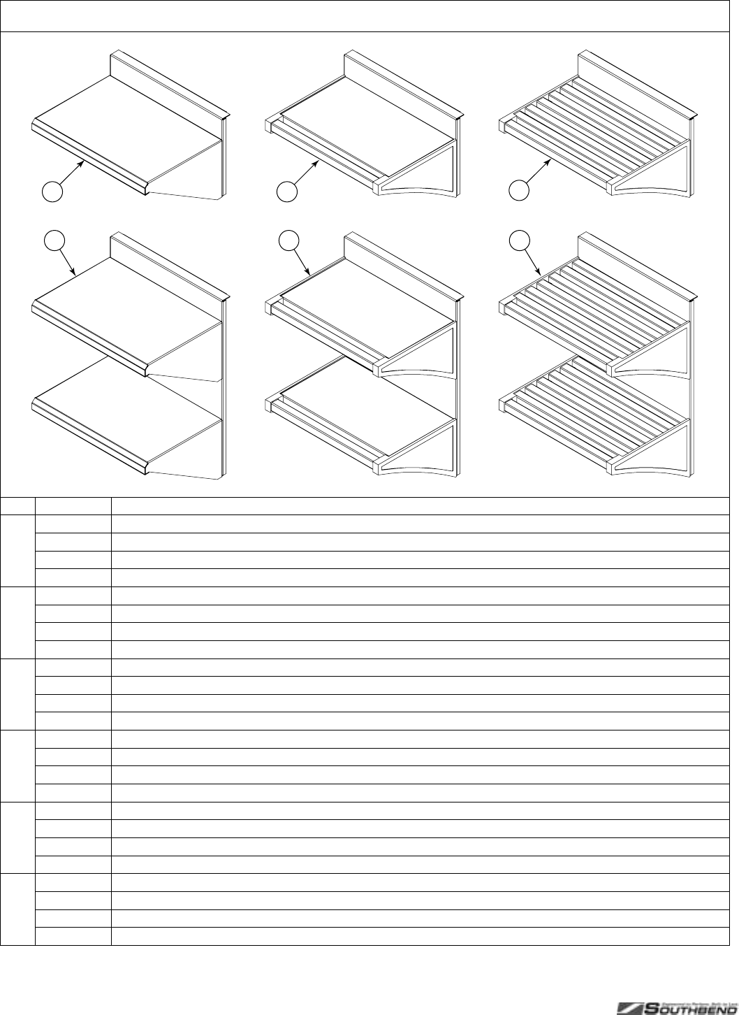
SERVICE PLATINUM SERIES SECTIONAL RANGE
PAGE 76 OF 80 INSTALL & OPERATIONS MANUAL 1185836 REV 3 (07/06)
Shelf Parts
1
4
2
5
3
6
Key Part Number Description
1 1185870 SINGLE SOLID SHELF ASM, 12"
1185686 SINGLE SOLID SHELF ASM, 16"
1185685 SINGLE SOLID SHELF ASM, 32"
1185687 SINGLE SOLID SHELF ASM, 48"
2 1185874 SINGLE TRAY SHELF ASM, 12"
1185875 SINGLE TRAY SHELF ASM, 16"
1184751 SINGLE TRAY SHELF ASM, 32"
1185876 SINGLE TRAY SHELF ASM, 48"
3 1185880 SINGLE TUBE SHELF ASM, 12"
1185881 SINGLE TUBE SHELF ASM, 16"
1184755 SINGLE TUBE SHELF ASM, 32"
1185882 SINGLE TUBE SHELF ASM, 48"
4 1185871 DOUBLE SOLID SHELF ASM, 12"
1185689 DOUBLE SOLID SHELF ASM, 16"
1185688 DOUBLE SOLID SHELF ASM, 32"
1185690 DOUBLE SOLID SHELF ASM, 48"
5 1185877 DOUBLE TRAY SHELF ASM, 12"
1185878 DOUBLE TRAY SHELF ASM, 16"
1184753 DOUBLE TRAY SHELF ASM, 32"
1185879 DOUBLE TRAY SHELF ASM, 48"
6 1185883 DOUBLE TUBE SHELF ASM, 12"
1185884 DOUBLE TUBE SHELF ASM, 16"
1184757 DOUBLE TUBE SHELF ASM, 32"
1185885 DOUBLE TUBE SHELF ASM, 48"

PLATINUM SERIES SECTIONAL RANGE SERVICE
INSTALL AND OPERATIONS MANUAL 1185836 REV 3 (07/06) PAGE 77 OF 80
Side Panel and Battery-Assembly Parts
Part Number Description
1183547 TRIM, SIDE (if side is not adjacent to another section of a battery)
1183563 TRIM, SIDE (if side is adjacent to an open-burner section of a battery)
1183564 TRIM, SIDE (if side is adjacent to a griddle or charbroiler section of a battery)
1183556 BODY SIDE, 32 SS RT
1183555 BODY SIDE, 32 SS LT
1184561 BODY SIDE, 32 SS OPEN RT
1184562 BODY SIDE, 32 SS OPEN LT
1184575 BODY SIDE, 32 CAB SS RT
1184556 BODY SIDE, 32 CAB SS LT
1184576 BODY SIDE, 32 CAB SS OPEN RT
1184563 BODY SIDE, 32 CAB SS OPEN LT
1183671 BODY SIDE, HALF AZ RT
1183672 BODY SIDE, HALF AZ LT
1183538 BODY SIDE, SS COUNTERTOP RT
1183553 BODY SIDE, SS COUNTERTOP LT
1184564 BODY SIDE, SS OPEN COUNTERTOP RT
1184565 BODY SIDE, SS OPEN COUNTERTOP LT
1184778 PLATE, FT/RR BATTERY CONNECT
1184779 PLATE, RISER BATTERY CONNECT
1184570 TRIM, FRONT 32 OVN-32 OVN
1184569 TRIM, FRONT 32 OVN-32 CAB
1184568 TRIM, FRONT 32 OVN-CAB
1183664 TRIM, FRONT 32 CAB-32 CAB
1183663 TRIM, FRONT CAB-32 OVN
1183665 TRIM, FRONT CAB-CAB
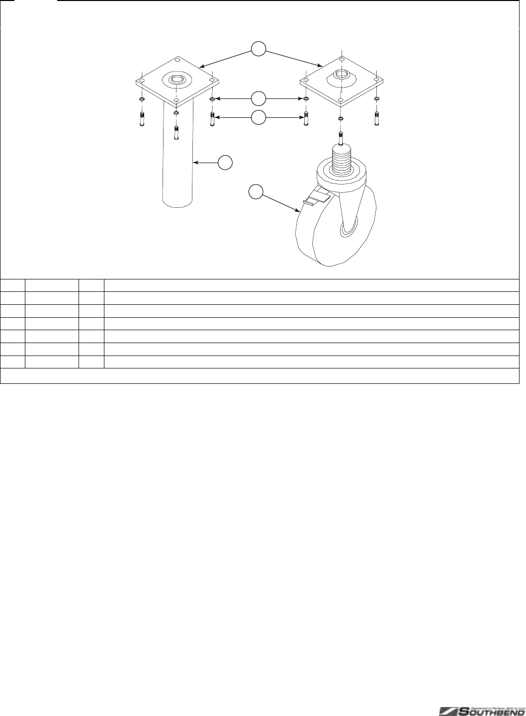
SERVICE PLATINUM SERIES SECTIONAL RANGE
PAGE 78 OF 80 INSTALL & OPERATIONS MANUAL 1185836 REV 3 (07/06)
Fi
g
ure 43
Leg and Caster Parts
4
5
1
2
3
Key Part Number Qty Description
1 1172650 4 LEG PAD (3/4 X 10 HOLE)
2 1146500 16 1/4 LOCK WASHER
3 1146201 16 1/4 X 30 X 3/4 HEX HEAD
4 1174260 1 LEG PACKAGE (set of four legs, not including bolts, leg pads, or lock washers)
* 1174262 1 EARTHQUAKE LEGS SS (set of four)
5 1174265 1 CASTER PACKAGE (two casters with brake and two without brake; does not include bolts, lock washers, or leg pads)
* Not shown in drawing.

PLATINUM SERIES SECTIONAL RANGE
INSTALL AND OPERATIONS MANUAL 1185836 REV 3 (07/06) PAGE 79 OF 80
Notes:

PLATINUM SERIES SECTIONAL RANGE
PAGE 80 OF 80 INSTALL & OPERATIONS MANUAL 1185836 REV 3 (07/06)
SECTIONAL RANGE
A product with the Southbend name incorporates the best in durability and low maintenance. We all recognize,
however, that replacement parts and occasional professional service may be necessary to extend the useful life of
this appliance. When service is needed, contact a Southbend Authorized Service Agency, or your dealer. To avoid
confusion, always refer to the model number, serial number, and type of your appliance.
Southbend
1100 Old Honeycutt Road, Fuquay-Varina, NC 27526
www.southbendnc.com
