Southbend Sb1016 Users Manual 36 10.05.12
sb1016 to the manual d5305a48-82fb-4752-b2fb-5bed6f5a1170
2015-02-02
: Southbend Southbend-Sb1016-Users-Manual-447639 southbend-sb1016-users-manual-447639 southbend pdf
Open the PDF directly: View PDF ![]() .
.
Page Count: 144 [warning: Documents this large are best viewed by clicking the View PDF Link!]

Hundreds of Thousands of Lathes Sold With a Tradition of
Q
uality Since 1906!
© August, 2010 by South Bend Lathe Co. For Machines Mfg. Since 7/09
OWNER'S MANUAL
18" & 60" EVS TOOLROOM LATHES
MODEL SB1016 - 220V Three Phase
MODEL SB1036 - 440V Three Phase

Customer Service
We stand behind our machines. If you have any service questions, parts requests or general questions
about your purchase, feel free to contact us.
South Bend Lathe Co.
P.O. Box 2027
Bellingham, WA 98227
Fax: (360) 676-1075 (International)
Fax: (360) 734-1639 (USA Only)
Email: cs@southbendlathe.com
Updates
For your convenience, any updates to this manual will be available to download free of charge
through our website at:
www.southbendlathe.com
Scope of Manual
This manual helps the reader understand the machine, how to prepare it for operation, how to control
it during operation, and how to keep it in good working condition. We assume the reader has a basic
understanding of how to operate this type of machine, but that the reader is not familiar with the
controls and adjustments of this specific model. As with all machinery of this nature, learning the
nuances of operation is a process that happens through training and experience. If you are not an
experienced operator of this type of machinery, read through this entire manual, then learn more
from an experienced operator, schooling, or research before attempting operations. Following this
advice will help you avoid serious personal injury and get the best results from your work.
Manual Feedback
We've made every effort to be accurate when documenting this machine. However, errors sometimes
happen or the machine design changes after the documentation process—so the manual may not
exactly match your machine. If a difference between the manual and machine leaves you in doubt,
contact our customer service for clarification.
We highly value customer feedback on our manuals. If you have a moment, please share your
experience using this manual. What did you like about it? Is there anything you would change to
make it better? Did it meet your expectations for clarity, professionalism, and ease-of-use?
South Bend Lathe, Inc.
C/O Technical Documentation Manager
P.O. Box 2027
Bellingham, WA 98227
Email: manuals@southbendlathe.com
Table of Contents
INTRODUCTION .................................................... 3
About These Machines.........................................3
Foreword ............................................................. 3
Capabilities .........................................................3
Features ..............................................................3
Identification ........................................................ 4
SAFETY ................................................................11
Understanding Risks of Machinery ..................11
Basic Machine Safety ........................................ 11
Additional Metal Lathe Safety ..........................13
PREPARATION ....................................................14
Preparation Overview ........................................14
Things You'll Need .............................................14
Power Supply Requirements .............................15
Availability ........................................................ 15
Full-Load Current Rating ..................................15
Circuit Information ............................................ 15
Circuit Requirements for 220V (Model SB1016) ..15
Circuit Requirements for 440V (Model SB1036) ..15
Grounding Requirements ...................................16
Correcting Phase Polarity (Yaskawa Drive) ........ 16
Unpacking ..........................................................18
Inventory ............................................................18
Cleaning & Protecting ....................................... 19
Location ..............................................................20
Physical Environment ........................................ 20
Electrical Installation ........................................20
Lighting ............................................................20
Weight Load ...................................................... 20
Space Allocation ................................................20
Lifting & Moving ................................................ 21
Leveling & Mounting ......................................... 22
Leveling ............................................................22
Bolting to Concrete Floors ..................................22
Assembly ............................................................23
Lubricating Lathe .............................................. 23
Adding Cutting Fluid .........................................23
Connecting to Power ..........................................24
Test Run .............................................................25
Spindle Break-In ................................................28
Recommended Adjustments .............................. 30
OPERATION ........................................................31
Operation Overview ...........................................31
Description of Controls & Components ............32
Main Power Control ...........................................32
Headstock Controls ............................................ 32
Control Panel ....................................................32
Carriage Controls ..............................................33
Tailstock Controls .............................................. 34
Chuck & Faceplate Mounting ...........................35
Removing Chuck or Faceplate ............................ 35
Mounting Chuck or Faceplate ............................36
Installing and Adjusting Camlock Studs ............. 37
3-Jaw Chuck ....................................................... 39
Changing Jaws .................................................. 39
Mounting Workpiece ..........................................40
4-Jaw Chuck ....................................................... 40
Mounting Workpiece ..........................................40
Tailstock .............................................................41
Offsetting ............................................................42
Installing Tooling ..............................................42
Aligning ............................................................44
Faceplate ............................................................46
Mounting Workpiece with Clamps ......................46
Mounting Workpiece Between Centers ............... 46
Centers ...............................................................47
Dead Centers .....................................................47
Live Centers ...................................................... 47
Mounting Center in Spindle ............................... 47
Removing Center from Spindle ........................... 47
Mounting Center in Tailstock ............................. 48
Removing Center from Tailstock ........................48
Steady Rest ........................................................ 48
Follow Rest ......................................................... 49
Compound Slide .................................................49
4-Way Tool Post ................................................. 50
Aligning Cutting Tool with Spindle Centerline ...50
Micrometer Stop.................................................51
Manual Feed ......................................................52
Carriage Handwheel ..........................................52
Compound Slide Handwheel ..............................52
Spindle Speed .....................................................52
Determining Spindle Speed ................................ 52
Setting Spindle Speed ........................................ 53
Power Feed .........................................................54
Power Feed Controls ..........................................54
Threading ...........................................................56
Power Feed Lever ..............................................56
Half Nut Lever ..................................................56
Thread Dial & Chart Overview ..........................56
Using Thread Dial and Chart .............................57
Understanding Thread & Feed Rate Chart ......... 59
Positioning Gearbox Levers ................................ 59
Repositioning Change Gears ..............................60
Cutting Fluid System ........................................ 61
ACCESSORIES ...................................................62
MAINTENANCE ...................................................64
Maintenance Schedule .......................................64
Cleaning .............................................................64
Maintenance Chart ............................................65
Lubrication ......................................................... 66
Headstock .........................................................66
Quick Change Gearbox ......................................69
Apron ................................................................ 70
Lead Screw ........................................................70
Ways & Slides ...................................................70
Unpainted & Machined Surfaces ........................71
Ball Oilers ......................................................... 71
Change Gears ................................................... 72
Cutting Fluid System ........................................ 73
Hazards.............................................................73
Adding Fluid .....................................................73
Changing Cutting Fluid ..................................... 74
Cleaning Electrical Box ...................................... 75
Machine Storage ................................................76
SERVICE .............................................................. 77
Backlash Adjustment ........................................ 77
Compound Leadscrew ........................................ 77
Cross Slide Leadscrew .......................................77
Leadscrew End Play Adjustment ......................78
Gib Adjustment .................................................. 78
Compound & Cross Slide Gibs ............................78
Saddle Gibs .......................................................79
Tailstock Gib .....................................................80
Half Nut Adjustment .........................................80
V-Belts ................................................................ 81
Brake Inspection & Replacement ..................... 82
Leadscrew Shear Pin Replacement ..................85
Gap Removal & Installation ..............................87
TROUBLESHOOTING ......................................... 88
ELECTRICAL ........................................................91
Electrical Safety Instructions ...........................91
Wiring Overview ................................................92
SB1016/36 Component Location Index ............. 93
SB1016/36 Electrical Box Wiring ...................... 94
SB1016/36 Electrical Box Wiring ...................... 95
SB1016/36 Electrical Box .................................. 96
SB1016 220V Spindle Motor .............................97
SB1036 440V Spindle Motor .............................97
SB1016 220V
Oil Pump Motor & Pressure Sensor .................98
SB1036 440V
Oil Pump Motor & Pressure Sensor .................98
SB1016 220V Coolant Pump Wiring .................99
SB1036 440V Coolant Pump Wiring .................99
SB1016/36 Control Panel Wiring ....................100
SB1016/36 Spindle Rotation Switch ............... 101
SB1016/36 Power Connection .........................101
SB1016/36 Additional Component Wiring ..... 102
PARTS ................................................................103
Headstock Controls ..........................................103
Headstock Internal Gears ...............................105
Headstock Transfer Gears ...............................107
Gearbox Gears .................................................. 109
Gearbox Controls A .......................................... 111
Gearbox Controls B .......................................... 112
Apron Front ......................................................114
Apron Rear ....................................................... 115
Compound Slide & Tool Post ...........................118
Cross Slide & Saddle A ....................................119
Cross Slide & Saddle B ....................................120
Bed & Shafts ....................................................122
End Gears ......................................................... 124
Motor & Lubrication ........................................ 125
Cabinets & Panels ........................................... 127
Tailstock ...........................................................129
Thread Dial ...................................................... 131
Micrometer Stop...............................................131
Steady Rest ...................................................... 132
Follow Rest ....................................................... 133
Brake System ................................................... 134
Electrical Cabinet & Control Panel ................135
Accessories .......................................................137
Front Machine Labels ...................................... 138
Rear Machine Labels .......................................139
WARRANTY & RETURNS .................................141

INTRODUCTION
For Machines Mfg. Since 7/09 Model SB1016/SB1036
-3-
INTRODUCTION
About These Machines
Foreword
"The screw cutting engine lathe is the oldest and
most important of machine tools and from it all
other machine tools have been developed. It was
the lathe that made possible the building of the
steamboat, the locomotive, the electric motor, the
automobile and all kinds of machinery used in
industry. Without the lathe our great industrial
progress of the last century would have been
impossible." —How To Run a Lathe, 15th
Edition, South Bend Lathe.
The lathes represented in this manual are a
modern day version of the screw cutting lathes
that trace their roots back to the 1700's, which
were themselves technological improvements of
the bow lathe that can be traced back thousands
of years to the ancient Egyptians.
Now, almost 300 years later, these modern
"screw cutting" lathes are not just a piece of
refined machinery, but a culmination of human
ingenuity and knowledge embodied into the
design and synergy of thousands of interworking
parts—some of which represent the life's work
and dreams of many inventors, mechanical
engineers, and world-class machinists—including
the likes of Leonardo da Vinci, Henry Maudsley,
and the founders of South Bend Lathe, John and
Miles O'Brien.
And now the torch is passed to you—to take
the oldest and most important type of machine
tool—and carry on the tradition. As the operator
of a South Bend Lathe, you now join the ranks
of some very famous and important customers,
such as Henry Ford, who used the machines he
purchased to help him change the world.
Features
As the name implies, these lathes feature EVS
(Electronic Variable Speed) spindle control,
which allows the operator to quickly adjust
the spindle speed. First, within the 18–1800
RPM range, one of four headstock gear ranges
is selected using the spindle speed range
lever. Next, the EVS dial is used to dial in any
available speed within that range. Lastly, a
digital tachometer displays the current spindle
speed.
The beds of these lathes are constructed with
Meehanite castings that have been precision
hardened and ground in the traditional 3-V
prismatic design—long used on South Bend
Lathes for its accuracy, durability, and rigidity.
The headstock features quick-change gear levers
and an adjustable clutch mechanism for the feed
rod that can be set to prevent damage in the
event of a carriage or cross feed bind from too
deep of a cut.
To further ensure a high degree of accuracy,
these lathes are equipped with high-grade
spindle bearings. The spindles are the D1-8
camlock type with an MT#7 taper and 3.125"
bore. The tailstock quills have an MT#5 taper
and offer 6.5" of travel.
Compared to conventional splash and spray oil
systems that can leave upper bearings and gears
starved for oil on initial start up and during
low speed operations, the EVS lathes have a
pressurized headstock oiling system. All bearings
and gears are pre-lubricated before the spindle
starts, so lubrication during high-load low-speed
operations is guaranteed.
Finally, these EVS toolroom lathes are packed
with a premium Yaskawa Inverter unit, Allen-
Bradley contactors, thermal relays, and fuse
system. A complete cutting fluid system is
included with an easy-to-clean chip drawer,
Way lubrication system, ball bearing steady rest
and brass-tipped follow rest, adjustable work
lamp, foot brake, and powered X and Y feed
capabilities.
Capabilities
These EVS Toolroom Lathes are built for daily
use in a busy industrial setting. Loaded with
many nice features and high-precision parts,
these lathes excel at making fine tools, dies,
thread gauges, jigs, and precision test gauges—
however, they are by no means delicate. Thick
castings, heavy weight, and quality construction
throughout provide the necessary brawn for
demanding production and manufacturing tasks.
-4-
For Machines Mfg. Since 7/09
Model SB1016/SB1036 INTRODUCTION
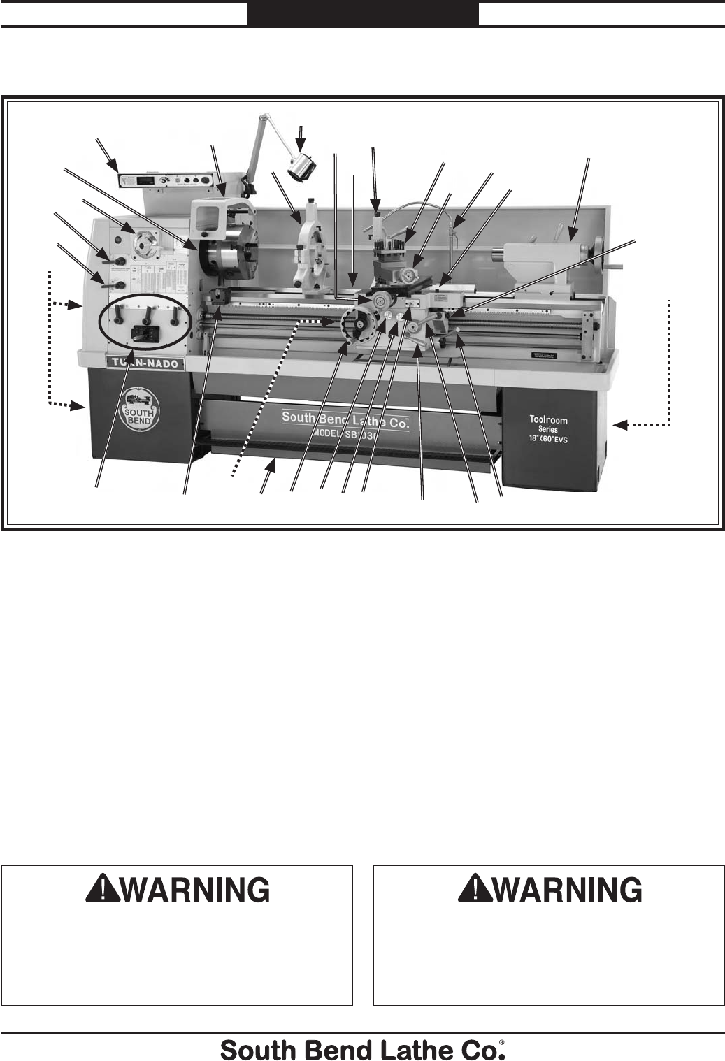
Identification
Serious personal injury could occur if
you connect the machine to power before
completing the setup process. DO NOT
connect power until instructed to do so later
in this manual.
Untrained users have an increased risk
of seriously injuring themselves with this
machine. Do not operate this machine until
you have understood this entire manual and
received proper training.
P. Half Nut Lever
Q. Feed ON/OFF Lever
R. Way Oil Pump
S. Apron Feed Direction Knob
T. Feed Selection Knob
U. Carriage Handwheel w/Safety Position
V. Brake Pedal
W. Adjustable Feed Clutch Knob
X. Micrometer Stop
Y. Quick Change Gearbox Levers
Z. Headstock Oil Pump & Reservoir Access
AA. Headstock Feed Direction Lever
AB. Quick Change Range Lever
AC. Spindle Speed and Range Lever
AD. D1-8 Camlock MT#7 Spindle
A. Control Panel
B. Chuck Guard w/Safety Switch
C. Steady Rest w/Ball Bearing Fingers
D. Halogen Work Lamp
E. Cross Slide Handwheel
F. Three-Vee Bed and Way System
G. Follow Rest w/Brass Fingers
H. 4-Way Tool Post
I. Compound Rest Handwheel
J. Cutting Fluid Nozzle
K. Carriage Lock
L. Double-Clamping Tailstock
M. Thread Dial for Cutting Inch Threads
N. Cutting Fluid Pump/Tank
O. Spindle ON/OFF Lever
Figure 1. The 18" x 60" Variable Speed Toolroom Lathe (EVS).
AB
C
D
E
FHL
K
M
O
YV
X
Z
QP
N
R
WT
US
I
J
G
AB
AA
AC
AD

For Machines Mfg. Since 7/09 Model SB1016/SB1036
-5-
INTRODUCTION
0RGHO6%
6RXWK%HQG[/DWKH9
2TQFWEV&KOGPUKQPU
9GKIJV NDU
9KFVJUKFGVQUKFGZ&GRVJHTQPVVQDCEMZ*GKIJV ZZKP
(QQVRTKPV.GPIVJZ9KFVJ ZKP
5JKRRKPI&KOGPUKQPU
6[RG 9QQF5NCV%TCVG
%QPVGPV /CEJKPG
9GKIJV NDU
.GPIVJZ9KFVJZ*GKIJV ZZKP
'NGEVTKECN
2QYGT4GSWKTGOGPV 82JCUG*\
(WNN.QCF%WTTGPV4CVKPI #
/KPKOWO%KTEWKV5K\G #OR
+PXGTVGT6[RG ;CUMCYC)#
5YKVEJ /CIPGVKEYKVJ6JGTOCN2TQVGEVKQP
5YKVEJ8QNVCIG 8
2NWI+PENWFGF 0Q
4GEQOOGPFGF2NWI1WVNGV6[RG *CTFYKTGVQ.QEMKPI&KUEQPPGEV5YKVEJ
/QVQTU
/CKP
6[RG 6'(%+PFWEVKQP
*QTUGRQYGT *2
8QNVCIG 8
2JCUG 2JCUG
#ORU #
5RGGF Ō42/
%[ENG *\
0WODGTQH5RGGFU 8CTKCDNG
2QYGT6TCPUHGT 8$GNV)GCT
$GCTKPIU 5JKGNFGFCPF2GTOCPGPVN[5GCNGF

-6-
For Machines Mfg. Since 7/09
Model SB1016/SB1036 INTRODUCTION
.WDTKECVKQP
6[RG 6'(%+PFWEVKQP
*QTUGRQYGT *2
8QNVCIG 8
2JCUG 2JCUG
#ORU #
5RGGF 42/
%[ENG *\
0WODGTQH5RGGFU
2QYGT6TCPUHGT &KTGEV&TKXG
$GCTKPIU 5JKGNFGFCPF2GTOCPGPVN[5GCNGF
%QQNCPV
6[RG 6'(%+PFWEVKQP
*QTUGRQYGT *2
8QNVCIG 8
2JCUG 2JCUG
#ORU #
5RGGF 42/
%[ENG *\
0WODGTQH5RGGFU
2QYGT6TCPUHGT &KTGEV&TKXG
$GCTKPIU 5JKGNFGFCPF2GTOCPGPVN[5GCNGF
/CKP5RGEKHKECVKQPU
1RGTCVKQP+PHQ
5YKPI1XGT$GF KP
&KUVCPEG$GVYGGP%GPVGTU KP
5YKPI1XGT%TQUU5NKFG KP
5YKPI1XGT5CFFNG KP
5YKPI1XGT)CR KP
/CZKOWO6QQN$KV5K\G KP
%QORQWPF6TCXGN KP
%CTTKCIG6TCXGN KP
%TQUU5NKFG6TCXGN KP
*GCFUVQEM+PHQ
5RKPFNG$QTG KP
5RKPFNG6CRGT /6
5RKPFNG5RGGFU Ō42/
5RKPFNG6[RG &%CONQEM
5RKPFNG$GCTKPIU (#)QT5-(6CRGTGF4QNNGT
5RKPFNG.GPIVJ KP
5RKPFNG.GPIVJYKVJ,CY%JWEM KP
5RKPFNG.GPIVJYKVJ,CY%JWEM KP
6CKNUVQEM+PHQ
6CKNUVQEM3WKNN6TCXGN KP
6CKNUVQEM6CRGT /6
6CKNUVQEM$CTTGN&KCOGVGT KP

For Machines Mfg. Since 7/09 Model SB1016/SB1036
-7-
INTRODUCTION
6JTGCFKPI+PHQ
0WODGTQH.QPIKVWFKPCN(GGFU
4CPIGQH.QPIKVWFKPCN(GGFU ŌKP
0WODGTQH%TQUU(GGFU
4CPIGQH%TQUU(GGFU ŌKP
0WODGTQH+PEJ6JTGCFU
4CPIGQH+PEJ6JTGCFU Ō62+
0WODGTQH/GVTKE6JTGCFU
4CPIGQH/GVTKE6JTGCFU ŌOO
0WODGTQH/QFWNCT2KVEJGU
4CPIGQH/QFWNCT2KVEJGU Ō/2
0WODGTQH&KCOGVTCN2KVEJGU
4CPIGQH&KCOGVTCN2KVEJGU &2
&KOGPUKQPU
$GF9KFVJ KP
.GCFUETGY&KCOGVGT KP
.GCFUETGY62+
.GCFUETGY.GPIVJ KP
5VGCF[4GUV%CRCEKV[ ŌKP
(QNNQY4GUV%CRCEKV[ ŌKP
(CEGRNCVG5K\G KP
(GGF4QF&KCOGVGT KP
(NQQTVQ%GPVGT*GKIJV KP
*GKIJV9KVJ.GXGNKPI,CEMU KP
%QPUVTWEVKQP
$CUG %CUV+TQP
*GCFUVQEM %CUV+TQP
*GCFUVQEM)GCTU (NCOG*CTFGPGF5VGGN
$GF +PFWEVKQP*CTFGPGFCPF)TQWPF/GGJCPKVG%CUV+TQP
5VCPF %CUV+TQP
1VJGT
%QWPVT[1H1TKIKP 6CKYCP5QOG%QORQPGPVU/CFGKP75#CPF)GTOCP[
9CTTCPV[ ;GCT
5GTKCN0WODGT.QECVKQP +&.CDGNQP4GCT5KFGQH.GHV5VCPF
#UUGODN[6KOG #RRTQZKOCVGN[*QWTU
5QWPF4CVKPI F$
(GCVWTGU
#NNGP$TCFNG['NGEVTKECN%QORQPGPVU
/GGJCPKVG%CUVKPI5KIPCVWTG5QWVJ$GPF89C[$GF
5CHGV[%JWEM)WCTFYKVJ/KETQ5YKVEJ5JWV1HH
*CNQIGP9QTM.KIJV
9C[6QQN2QUV
%QORNGVG%QQNCPV5[UVGO
/KETQOGVGT%CTTKCIG5VQR
6JTGCFKPI&KCN+PFKECVQT
(#)QT5-()GTOCP5RKPFNG$GCTKPIU
(WNN.GPIVJ5RNCUJ)WCTF
(TQPV4GOQXCDNG5NKFKPI%JKR6TC[
;CUMCYC)#+PXGTVGT
%QORNGVGN['PENQUGF7PKXGTUCN)GCTDQZHQT%WVVKPI+PEJ/GVTKE/QFWNCTCPF&KCOGVTCN2KVEJGU
2TGUUWTK\GF.WDTKECVKQP5[UVGOHQT*GCFUVQEM)GCTUCPF$GCTKPIU
&KCN%QPVTQNNGF8CTKCDNG5RKPFNG5RGGFUYKVJ&KIKVCN4GCF1WV
,QI$WVVQPCPF'OGTIGPE[5VQR

-8-
For Machines Mfg. Since 7/09
Model SB1016/SB1036 INTRODUCTION
0RGHO6%
6RXWK%HQG[/DWKH9
2TQFWEV&KOGPUKQPU
9GKIJV NDU
9KFVJUKFGVQUKFGZ&GRVJHTQPVVQDCEMZ*GKIJV ZZKP
(QQVRTKPV.GPIVJZ9KFVJ ZKP
5JKRRKPI&KOGPUKQPU
6[RG 9QQF5NCV%TCVG
%QPVGPV 0QV#XCKNCDNG
9GKIJV NDU
.GPIVJZ9KFVJZ*GKIJV ZZKP
'NGEVTKECN
2QYGT4GSWKTGOGPV 82JCUG*\
(WNN.QCF%WTTGPV4CVKPI #
/KPKOWO%KTEWKV5K\G #
+PXGTVGT6[RG ;CUMCYC)#
5YKVEJ /CIPGVKEYKVJ6JGTOCN2TQVGEVKQP
5YKVEJ8QNVCIG 8
2NWI+PENWFGF 0Q
4GEQOOGPFGF2NWI1WVNGV6[RG *CTFYKTGVQ.QEMKPI&KUEQPPGEV5YKVEJ
/QVQTU
/CKP
6[RG 6'(%+PFWEVKQP
*QTUGRQYGT *2
8QNVCIG 8
2JCUG 2JCUG
#ORU #
5RGGF Ō42/
%[ENG *\
0WODGTQH5RGGFU 8CTKCDNG
2QYGT6TCPUHGT 8$GNV)GCT
$GCTKPIU 5JKGNFGFCPF2GTOCPGPVN[5GCNGF

For Machines Mfg. Since 7/09 Model SB1016/SB1036
-9-
INTRODUCTION
.WDTKECVKQP
6[RG 6'(%+PFWEVKQP
*QTUGRQYGT *2
8QNVCIG 8
2JCUG 2JCUG
#ORU #
5RGGF 42/
%[ENG *\
0WODGTQH5RGGFU
2QYGT6TCPUHGT &KTGEV&TKXG
$GCTKPIU 5JKGNFGFCPF2GTOCPGPVN[5GCNGF
%QQNCPV
6[RG 6'(%+PFWEVKQP
*QTUGRQYGT *2
8QNVCIG 8
2JCUG 2JCUG
#ORU #
5RGGF 42/
%[ENG *\
0WODGTQH5RGGFU
2QYGT6TCPUHGT &KTGEV&TKXG
$GCTKPIU 5JKGNFGFCPF2GTOCPGPVN[5GCNGF
/CKP5RGEKHKECVKQPU
1RGTCVKQP+PHQ
5YKPI1XGT$GF KP
&KUVCPEG$GVYGGP%GPVGTU KP
5YKPI1XGT%TQUU5NKFG KP
5YKPI1XGT5CFFNG KP
5YKPI1XGT)CR KP
/CZKOWO6QQN$KV5K\G KP
%QORQWPF6TCXGN KP
%CTTKCIG6TCXGN KP
%TQUU5NKFG6TCXGN KP
*GCFUVQEM+PHQ
5RKPFNG$QTG KP
5RKPFNG6CRGT /6
0WODGTQH5RKPFNG5RGGFU 8CTKCDNG
5RKPFNG5RGGFU Ō42/
5RKPFNG6[RG &%CONQEM
5RKPFNG$GCTKPIU (#)QT5-(6CRGTGF4QNNGT
5RKPFNG.GPIVJ
5RKPFNG.GPIVJYKVJ,CY%JWEM KP
5RKPFNG.GPIVJYKVJ,CY%JWEM KP
6CKNUVQEM+PHQ
6CKNUVQEM3WKNN6TCXGN KP
6CKNUVQEM6CRGT /6
6CKNUVQEM$CTTGN&KCOGVGT KP

-10-
For Machines Mfg. Since 7/09
Model SB1016/SB1036 INTRODUCTION
6JTGCFKPI+PHQ
0WODGTQH.QPIKVWFKPCN(GGFU
4CPIGQH.QPIKVWFKPCN(GGFU ŌKP
0WODGTQH%TQUU(GGFU
4CPIGQH%TQUU(GGFU ŌKP
0WODGTQH+PEJ6JTGCFU
4CPIGQH+PEJ6JTGCFU Ō62+
0WODGTQH/GVTKE6JTGCFU
4CPIGQH/GVTKE6JTGCFU ŌOO
0WODGTQH/QFWNCT2KVEJGU
4CPIGQH/QFWNCT2KVEJGU Ō/2
0WODGTQH&KCOGVTCN2KVEJGU
4CPIGQH&KCOGVTCN2KVEJGU &2
&KOGPUKQPU
$GF9KFVJ KP
.GCFUETGY&KCOGVGT KP
.GCFUETGY62+
.GCFUETGY.GPIVJ KP
5VGCF[4GUV%CRCEKV[ ŌKP
(QNNQY4GUV%CRCEKV[ ŌKP
(CEGRNCVG5K\G KP
(GGF4QF&KCOGVGT KP
(NQQTVQ%GPVGT*GKIJV KP
*GKIJV9KVJ.GXGNKPI,CEMU KP
%QPUVTWEVKQP
$CUG %CUV+TQP
*GCFUVQEM %CUV+TQP
*GCFUVQEM)GCTU %CUV+TQP
$GF +PFWEVKQP*CTFGPGFCPF)TQWPF/GGJCPKVG%CUV+TQP
5VCPF %CUV+TQP
1VJGT
%QWPVT[1H1TKIKP 6CKYCP5QOG%QORQPGPVU/CFGKP75#CPF)GTOCP[
9CTTCPV[ ;GCT
5GTKCN0WODGT.QECVKQP +&.CDGNQP4GCT5KFGQH.GHV5VCPF
#UUGODN[6KOG #RRTQZKOCVGN[*QWTU
5QWPF4CVKPI F$
(GCVWTGU
#NNGP$TCFNG['NGEVTKECN%QORQPGPVU
/GGJCPKVG%CUVKPI5KIPCVWTG5QWVJ$GPF89C[$GF
5CHGV[%JWEM)WCTFYKVJ/KETQ5YKVEJ5JWV1HH
*CNQIGP9QTM.KIJV
9C[6QQN2QUV
%QORNGVG%QQNCPV5[UVGO
/KETQOGVGT%CTTKCIG5VQR
6JTGCFKPI&KCN+PFKECVQT
(#)QT5-()GTOCP5RKPFNG$GCTKPIU
(WNN.GPIVJ5RNCUJ)WCTF
(TQPV4GOQXCDNG5NKFKPI%JKR6TC[
;CUMCYC)#+PXGTVGT
%QORNGVGN['PENQUGF7PKXGTUCN)GCTDQZHQT%WVVKPI+PEJ/GVTKE/QFWNCTCPF&KCOGVTCN2KVEJGU
2TGUUWTK\GF.WDTKECVKQP5[UVGOHQT*GCFUVQEM)GCTUCPF$GCTKPIU
&KCN%QPVTQNNGF8CTKCDNG5RKPFNG5RGGFUYKVJ&KIKVCN4GCF1WV
,QI$WVVQPCPF'OGTIGPE[5VQR

SAFETY
For Machines Mfg. Since 7/09 Model SB1016/SB1036
-11-
SAFETY
Understanding Risks of Machinery
Operating all machinery and machining equipment can be dangerous or relatively safe depending
on how it is installed and maintained, and the operator's experience, common sense, risk awareness,
working conditions, and use of personal protective equipment (safety glasses, respirators, etc.).
The owner of this machinery or equipment is ultimately responsible for its safe use. This
responsibility includes proper installation in a safe environment, personnel training and usage
authorization, regular inspection and maintenance, manual availability and comprehension,
application of safety devices, integrity of cutting tools or accessories, and the usage of approved
personal protective equipment by all operators and bystanders.
The manufacturer of this machinery or equipment will not be held liable for injury or property
damage from negligence, improper training, machine modifications, or misuse. Failure to read,
understand, and follow the manual and safety labels may result in serious personal injury, including
amputation, broken bones, electrocution, or death.
The signals used in this manual to identify hazard levels are defined as follows:
Death or catastrophic
harm WILL occur.
Moderate injury or fire
MAY occur.
Death or catastrophic
harm COULD occur.
Machine or property
damage may occur.
Basic Machine Safety
1. Owner’s Manual: All machinery and
machining equipment presents serious
injury hazards to untrained users. To
reduce the risk of injury, anyone who uses
THIS item MUST read and understand
this entire manual before starting.
2. Personal Protective Equipment: Operating
or servicing this item may expose the user
to flying debris, dust, smoke, dangerous
chemicals, or loud noises. These hazards
can result in eye injury, blindness, long-
term respiratory damage, poisoning,
cancer, reproductive harm or hearing loss.
Reduce your risks from these hazards
by wearing approved eye protection,
respirator, gloves, or hearing protection.
3. Trained/Supervised Operators Only:
Untrained users can seriously injure
themselves or bystanders. Only allow
trained and properly supervised personnel
to operate this item. Make sure safe
operation instructions are clearly
understood. If electrically powered, use
padlocks and master switches, and remove
start switch keys to prevent unauthorized
use or accidental starting.
4. Guards/Covers: Accidental contact with
moving parts during operation may cause
severe entanglement, impact, cutting,
or crushing injuries. Reduce this risk by
keeping any included guards/covers/doors
installed, fully functional, and positioned
for maximum protection.

-12-
For Machines Mfg. Since 7/09
Model SB1016/SB1036 SAFETY
5. Entanglement: Loose clothing, gloves,
neckties, jewelry or long hair may
get caught in moving parts, causing
entanglement, amputation, crushing,
or strangulation. Reduce this risk by
removing/securing these items so they
cannot contact moving parts.
6. Mental Alertness: Operating this item
with reduced mental alertness increases
the risk of accidental injury. Do not let a
temporary influence or distraction lead to a
permanent disability! Never operate when
under the influence of drugs/alcohol, when
tired, or otherwise distracted.
7. Safe Environment: Operating electrically
powered equipment in a wet environment
may result in electrocution; operating near
highly flammable materials may result in a
fire or explosion. Only operate this item in
a dry location that is free from flammable
materials.
8. Electrical Connection: With electically
powered equipment, improper connections
to the power source may result in
electrocution or fire. Always adhere to all
electrical requirements and applicable
codes when connecting to the power source.
Have all work inspected by a qualified
electrician to minimize risk.
9. Disconnect Power: Adjusting or servicing
electrically powered equipment while it
is connected to the power source greatly
increases the risk of injury from accidental
startup. Always disconnect power
BEFORE any service or adjustments,
including changing blades or other tooling.
10. Secure Workpiece/Tooling: Loose
workpieces, cutting tools, or rotating
spindles can become dangerous projectiles
if not secured or if they hit another object
during operation. Reduce the risk of this
hazard by verifying that all fastening
devices are properly secured and items
attached to spindles have enough clearance
to safely rotate.
11. Chuck Keys or Adjusting Tools: Tools used
to adjust spindles, chucks, or any moving/
rotating parts will become dangerous
projectiles if left in place when the machine
is started. Reduce this risk by developing
the habit of always removing these tools
immediately after using them.
12. Work Area: Clutter and dark shadows
increase the risks of accidental injury.
Only operate this item in a clean, non-
glaring, and well-lighted work area.
13. Properly Functioning Equipment: Poorly
maintained, damaged, or malfunctioning
equipment has higher risks of causing
serious personal injury compared to
those that are properly maintained.
To reduce this risk, always maintain
this item to the highest standards and
promptly repair/service a damaged or
malfunctioning component. Always follow
the maintenance instructions included in
this documentation.
14. Unattended Operation: Electrically
powered equipment that is left unattended
while running cannot be controlled and is
dangerous to bystanders. Always turn the
power OFF before walking away.
15. Health Hazards: Certain cutting fluids
and lubricants, or dust/smoke created
when cutting, may contain chemicals
known to the State of California to cause
cancer, respiratory problems, birth defects,
or other reproductive harm. Minimize
exposure to these chemicals by wearing
approved personal protective equipment
and operating in a well ventilated area.
16. Difficult Operations: Attempting
difficult operations with which you are
unfamiliar increases the risk of injury.
If you experience difficulties performing
the intended operation, STOP! Seek an
alternative method to accomplish the
same task, ask a qualified expert how the
operation should be performed, or contact
our Technical Support for assistance.

For Machines Mfg. Since 7/09 Model SB1016/SB1036
-13-
SAFETY
Additional Metal Lathe Safety
7. Speed Rates: Operating the lathe at the
wrong speed can cause nearby parts to break
or the workpiece to come loose, which will
result in dangerous projectiles that could
cause severe impact injury. Large workpieces
must be turned at slow speeds. Always use
the appropriate feed and speed rates.
8. Stopping Spindle by Hand: Stopping the spin-
dle by putting your hand on the workpiece or
chuck creates an extreme risk of entangle-
ment, impact, crushing, friction, or cutting
hazards. Never attempt to slow or stop the
lathe spindle with your hand. Allow the
spindle to come to a stop on its own or use the
brake.
9. Crashes: Driving the cutting tool or other
lathe components into the chuck may cause
an explosion of metal fragments, which can
result in severe impact injuries and major
damage to the lathe. Reduce this risk by
releasing automatic feeds after use, not leav-
ing lathe unattended, and checking clear-
ances before starting the lathe. Make sure no
part of the tool, tool holder, compound slide,
cross slide, or carriage will contact the chuck
during operation.
10. Long Stock Safety: Long stock can whip vio-
lently if not properly supported, causing seri-
ous impact injury and damage to the lathe.
Reduce this risk by supporting any stock that
extends from the chuck/headstock more than
three times its own diameter. Always turn
long stock at slow speeds.
11. Cutting Fluid Safety: Cutting fluid can be a
poisonous biohazard that may cause personal
injury from skin or eye contact. Incorrectly
positioned cutting fluid nozzles can splash
on the operator or the floor, resulting in an
exposure or slipping hazard. To decrease your
risk, wear the required personal protection
gear, change cutting fluid regularly, and posi-
tion the cutting fluid nozzle where it will not
splash or end up on the floor.
1. Clearing Chips: Metal chips can easily cut
bare skin—even through a piece of cloth.
Avoid clearing chips by hand or with a rag.
Use a brush or vacuum to clear metal chips.
2. Chuck Key Safety: A chuck key left in the
chuck can become a deadly projectile when
the spindle is started. Always remove the
chuck key after using it. Develop a habit of
not taking your hand off of a chuck key unless
it is away from the machine.
3. Tool Selection: Cutting with an incorrect
or dull tool increases the risk of accidental
injury. Dull tools require extra force when
cutting, which increases risk of breaking
or dislodging components, which can cause
small shards of metal to become dangerous
projectiles. Always select the right cutter for
the job and make sure it is sharp. A correct,
sharp tool decreases strain and provides a
better finish.
4. Securing Workpiece: An improperly secured
workpiece can fly off of the lathe spindle with
deadly force, which can result in a severe
impact injury. Make sure the workpiece is
properly secured in the chuck or faceplate
before starting the lathe.
5. Handling Chucks: Chucks can be very heavy
and difficult to grasp, which can lead to
crushed fingers or hands if mishandled.
Get assistance when installing or removing
chucks to reduce this risk. Protect your hands
and the precision-ground ways by using a
chuck cradle or piece of plywood over the
ways of the lathe when servicing chucks.
6. Safe Clearances: Workpieces that crash into
other components on the lathe may throw
dangerous projectiles in all directions, lead-
ing to impact injury and damaged equipment.
Before starting the spindle, make sure the
workpiece has adequate clearance by hand-
rotating it through its entire range of motion.
Also, check the tool and tool post clearance,
chuck clearance, and saddle clearance.

PREPARATION
-14-
For Machines Mfg. Since 7/09
Model SB1016/SB1036 PREPARATION
Preparation Overview Things You'll Need
To complete the preparation process, you will
need the following items:
For Lifting and Moving
s 4WOEXTRAPERSONSWITHGUIDERODSTOSTEADY
the lathe during lifting and moving.
s !&ORKLIFTOR/THER0OWER,IFTINGDEVICE
rated for at least 10,000 lbs.
s ,IFTINGStrap or Chain with Hook
rated for at least 10,000 lbs.
s Various Hardwood Blocks and Planks as
Needed
For Power Connection
s !POWERSOURCETHATMEETSTHEMINIMUM
circuit requirements for this machine (refer
to Page 16 for details).
s !QUALIFIEDELECTRICIANTOENSUREASAFEAND
code-compliant connection to the power
source.
For Assembly
s 0RECISION,EVEL
s Cotton Rags
s Mineral Spirits
s Quality Metal Protectant Oil
s 3AFETYGlasses
s Wrench or Socket 21mm
s Wrench or Socket 19mm
s &LOORMounting Hardware as Needed
s Standard Screwdriver #2
The purpose of the preparation section is to help
you prepare your machine for operation. The list
below outlines the basic process. Specific steps
for each of these points will be covered in detail
later in this section.
The typical preparation process is as follows:
1. Unpack the lathe and inventory the contents
of the box/crate.
2. Clean the lathe and its components.
3. Identify an acceptable location for the lathe
and move it to that location.
4. Level the lathe and either bolt it to the floor
or place it on mounts.
5. Assemble the loose components, lubricate the
lathe, and make any necessary adjustments
or inspections to ensure the lathe is ready for
operation.
6. Connect the lathe to the power source.
7. Test run the lathe to make sure it functions
properly and is ready for operation.
For Machines Mfg. Since 7/09 Model SB1016/SB1036
-15-
PREPARATION
Power Supply
Requirements
Electrocution or fire may
occur if machine is not
correctly grounded and
attached to the power
supply. Use a qualified
electrician to ensure a safe
power connection.
Before installing the machine, consider the
availability and proximity of the required power
supply circuit. If an existing circuit does not meet
the requirements for this machine, a new circuit
must be installed.
To minimize the risk of electrocution, fire,
or equipment damage, installation work and
electrical wiring must be done by a qualified
electrician in accordance with all applicable
codes and standards.
Availability
The full-load current rating is the amperage
a machine draws at 100% of the rated output
power. On machines with multiple motors, this is
the amperage drawn by the largest motor or sum
of all motors and electrical devices that might
operate at one time during normal operations.
The full-load current is not the maximum
amount of amps that the machine will draw. If
the machine is overloaded, it will draw additional
amps beyond the full-load rating.
If the machine is overloaded for a sufficient
length of time, damage, overheating, or fire may
result—especially if connected to an undersized
circuit. To reduce the risk of these hazards,
avoid overloading the machine during operation
and make sure it is connected to a power supply
circuit that meets the requirements in the
following section.
Full-Load Current Rating
Model SB1016 Full-Load Rating 220V ...... 30A
Model SB1036 Full-Load Rating 440V ...... 15A
For your own safety and protection of property,
consult a qualified electrician if you are unsure
about wiring practices or electrical codes in
your area.
Note: The circuit requirements listed in this
manual apply to a dedicated circuit—where only
one machine will be running at a time. If this
machine will be connected to a shared circuit
where multiple machines will be running at
the same time, consult a qualified electrician to
ensure that the circuit is properly sized for safe
operation.
A
power supply circuit includes all electrical
equipment between the main breaker box or fuse
panel in your building and the incoming power
connections inside the machine. This circuit must
be safely sized to handle the full-load current
that may be drawn from the machine for an
extended period of time.
Circuit Information
Circuit Requirements for 440V
(Model SB1036)
Nominal Voltage ............................... 440V/480V
Cycle .............................................................60 Hz
Phase .............................................. Three-Phase
Circuit Rating....................................... 20 Amps
Connection Type ..............Hardwire (Page 24)
This machine is prewired to operate on a 440V
power supply circuit that has a verified ground
and meets the following requirements:
This machine is equipped with a frequency
drive that contains sensitive electronics,
which can be damaged by a phase converter.
DO NOT use a phase converter to power this
machine. Doing so will void the warranty.
-16 -
For Machines Mfg. Since 7/09
Model SB1016/SB1036 PREPARATION
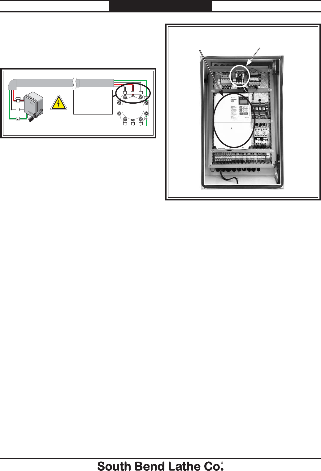
Correcting Phase Polarity
(Yaskawa Drive)
This sub-section is only provided for
troubleshooting by a qualified electrician. If
you discover during the test run that the lathe
will not operate, or that one or more motors run
backwards, incorrect phase polarity may be at
fault and will need to be corrected.
To establish the correct phase polarity:
1. Disconnect the machine from power, wait
15 minutes for the drive unit capacitors to
discharge.
— If the spindle motor rotates in the
incorrect direction, swap any two of the
output wires U, V, or W that are located
at the variable frequency drive shown in
Figure 3.
Note: Swapping any two of the L1, L2, or
L3 incoming power leads located at the
input of the machine or frequency drive
has no effect on spindle motor rotation.
U V W
79 8? 35 3? B# B$ B5 E5
E5 3# 3$ 3% H 35 H
E# E$ E% E& E' E( E) E*
?B B% 5% B& 5&
DB D D E E
E+ E#"E## E#$ #9
?3 ?4 ?5
?# ?$ 7
9
G7
Varispeed
N6H@6L6
K6G>67A:HE::9JC>I
G:;:GIDN6H@6L6DLC:GHB6CJ6A
11
10
17
15
16
L1 L2 L3 B1 B2
13 12 14
23
18
R/L1 S/L2 T/L3 1 2 B1 B2 U/T1 V/T2 W/T3
Swap any
Two of
These Wires
Figure 3. Spindle motor power supply wires at
variable frequency drive unit.
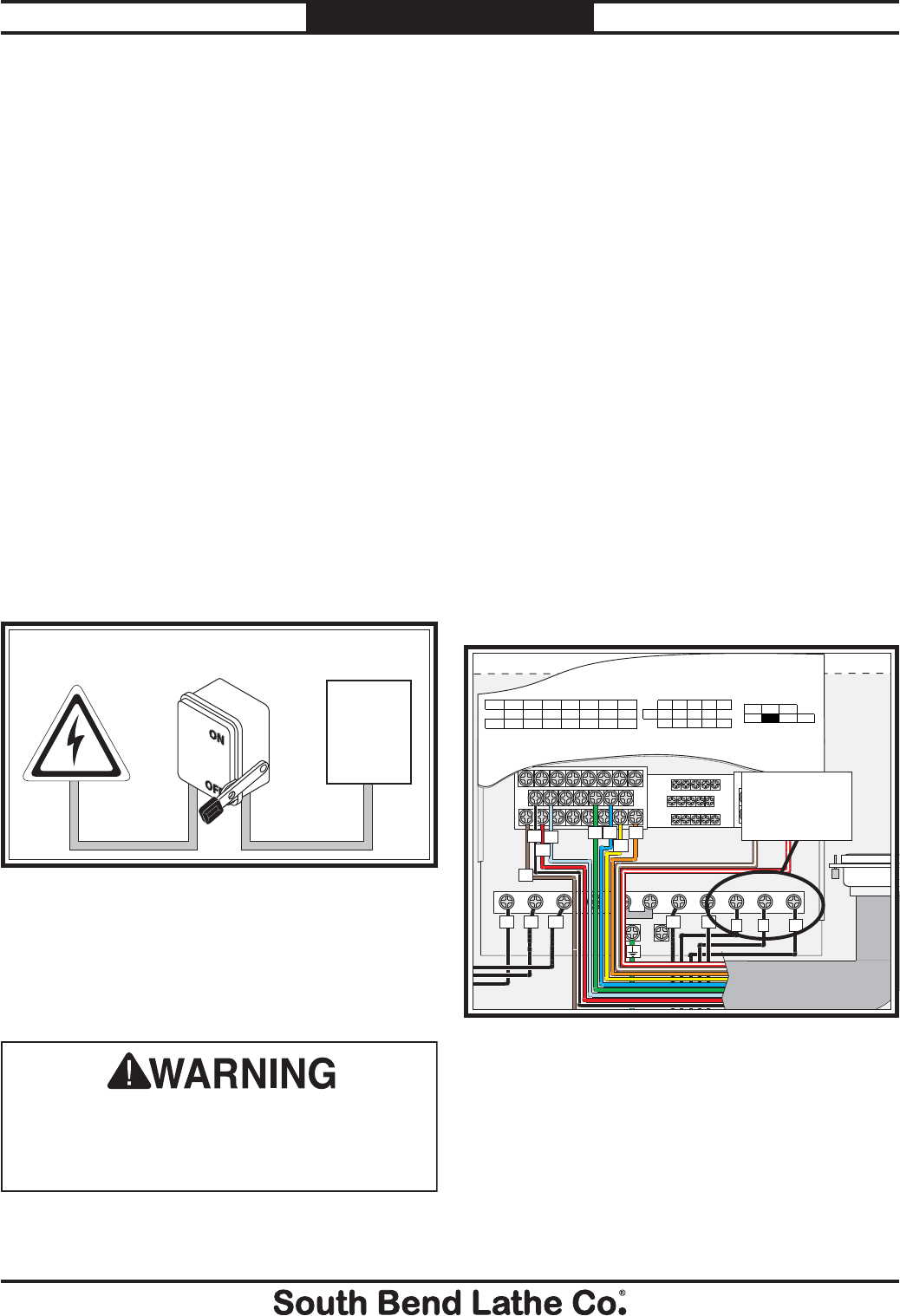
Grounding Requirements
In the event of certain types of malfunctions or
breakdowns, grounding provides a path of least
resistance for electric current—in order to reduce
the risk of electric shock.
Power supply connections that are hardwired
to the power source must be connected to a
grounded metal permanent wiring system, or
to a system having an equipment-grounding
conductor.
Figure 2. Typical hardwire setup with a locking
disconnect switch.
Serious injury could occur if you connect
the machine to power before completing the
setup process. DO NOT connect to power until
instructed later in this manual.
Due to the complexity required for planning,
bending, and installing the conduit necessary for
a hardwire setup, this type of setup can only be
performed by a qualified electrician.
Power Source
Locking
Disconnect Switch Machine
Conduit Conduit
This machine is prewired to operate on a 220V
power supply circuit that has a verified ground
and meets the following requirements:
Circuit Requirements for 220V
(Model SB1016)
Nominal Voltage ............................... 220V/240V
Cycle .............................................................60 Hz
Phase .............................................. Three-Phase
Circuit Rating....................................... 40 Amps
Connection Type ..............Hardwire (Page 24)
For Machines Mfg. Since 7/09 Model SB1016/SB1036
-17-
PREPARATION
— If one or more pump motors do not pump
or rotate in the incorrect direction, locate
the master power switch on the lathe,
and swap any two of the L1, L2, or L3
incoming power leads shown in Figure 4.
Ground
Hot
Hot
Hot DISCONNECT
SWITCH
(as recommended)L3
L2L1
MASTER
POWER SWITCH
L3
L3
L2
L2
L1
L1 1
2
35
6
4
Figure 4. Machine incoming power supply wires.
Swap any
Two of
These Wires
2. Close the electrical cabinet door, reinstall
motor covers and access panels, and test
machine operation.
Figure 5. Component locations in lathe electrical
cabinet.
Variable Frequency
Drive (Figure 3)
Master Power
Switch (Figure 4)
-18-
For Machines Mfg. Since 7/09
Model SB1016/SB1036 PREPARATION
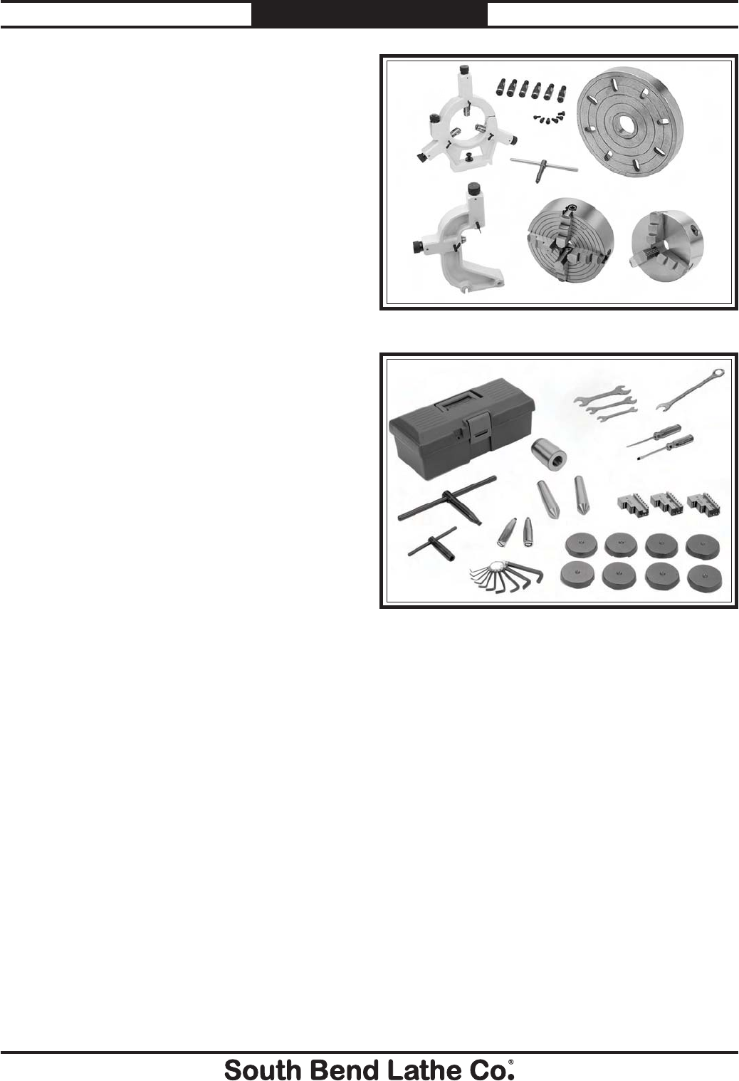
Inventory
Main Inventory 1: (Figure 6) Qty
A. Steady Rest Assembly .................................... 1
B. D1-8 Camlock Stud Set .................................. 1
C. 15" Faceplate w/D1-8 Camlock Stud Set ...... 1
D. 12" 3-Jaw Chuck w/OD Clamping Jaws ....... 1
E. 14" 4-Jaw Chuck w/Combo Jaws ...................1
F. 4-Jaw Chuck Key ........................................... 1
G. Follow Rest Assembly .................................... 1
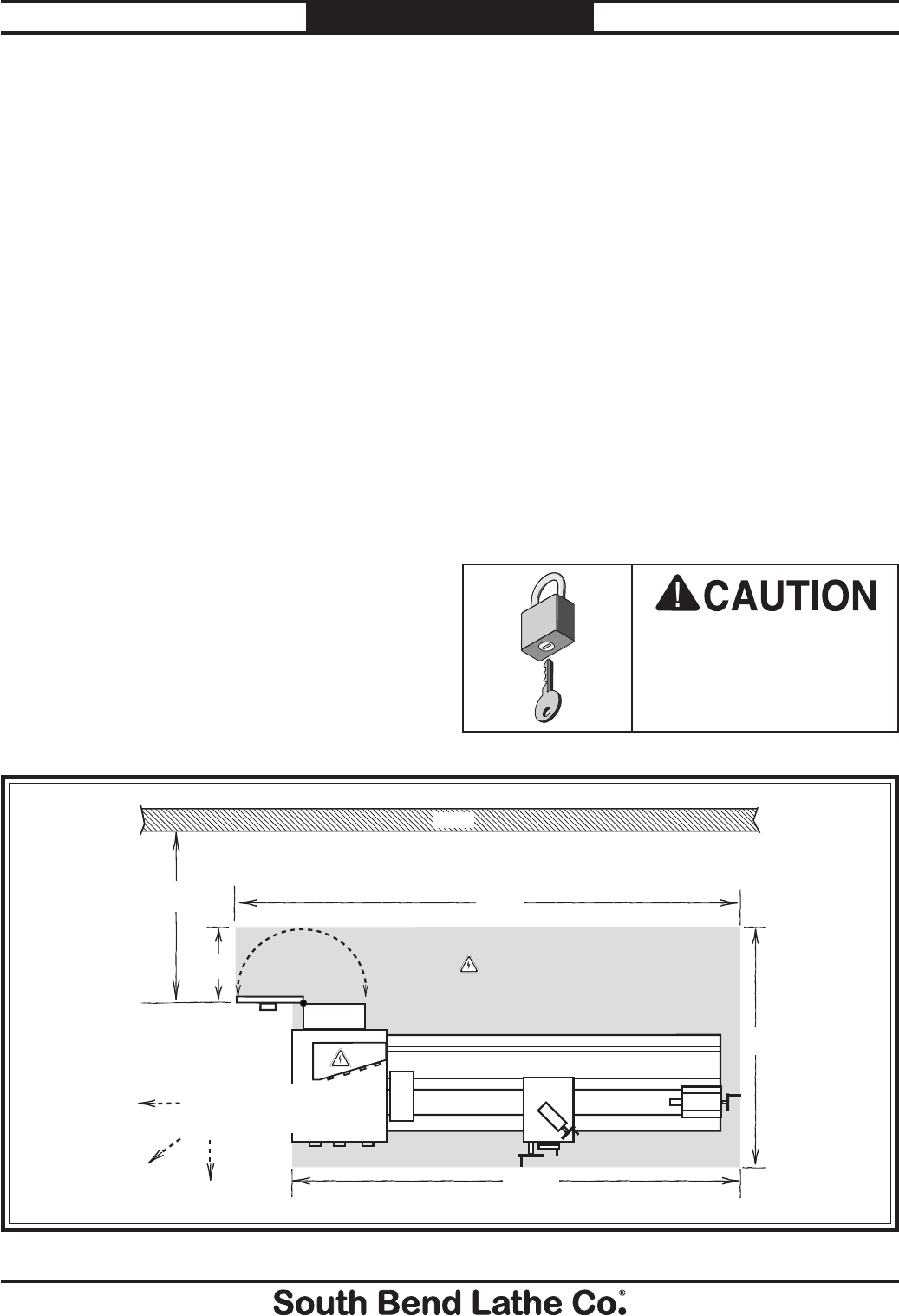
Tool Box Inventory: (Figure 7) Qty
H. Tool Box .......................................................... 1
I. 3-Jaw Chuck Key ........................................... 1
J. Tool Post T-Wrench ........................................ 1
K. Hex Wrench Set 1.5-10mm ............................ 1
L. Handwheel Handles .......................................2
M. Solid Dead Center MT#5 ............................... 1
N. Carbide-Tipped Dead Center MT#5 ..............1
O. Spindle Sleeve MT#7-MT#5 ..........................1
P. Open End Wrench 10/12mm ......................... 1
Q. Open End Wrench 14/17mm ......................... 1
R. Open End Wrench 22/24mm ......................... 1
S. Combo Wrench 27mm .................................... 1
T. Phillips Screwdriver #2 ................................. 1
U. Standard Screwdriver #2 ...............................1
V. ID Clamping Jaw Set (Three Jaw Chuck) ....1
W. Cast Iron Leveling Pads ................................8
Note: Some inventory components may be
shipped inside of the lathe electrical box. These
items MUST be removed before connecting the
lathe to the power source.
Figure 6. Main inventory.
A
B
C
D
E
G
Figure 7. Toolbox inventory.
H
I
J
K
MN
O
Q
R
P
S
T
U
V
L
W
Unpacking
This item was carefully packaged to prevent
damage during transport. If you discover any
damage, please immediately call Customer
Service at (360) 734-1540 for advice. You may
need to file a freight claim, so save the containers
and all packing materials for possible inspection
by the carrier or its agent.
F

For Machines Mfg. Since 7/09 Model SB1016/SB1036
-19-
PREPARATION
The unpainted surfaces are coated at the factory
with a heavy-duty rust preventative that
prevents corrosion during shipment and storage.
The benefit of this rust preventative is that it
works very well. The downside is that it can be
time-consuming to thoroughly remove.
Be patient and do a careful job when cleaning
and removing the rust preventative. The time
you spend doing this will reward you with
smooth-sliding parts and a better appreciation
for the proper care of the unpainted surfaces.
A
lthough there are many ways to successfully
remove the rust preventative, we have cleaned
thousands of machines and found the following
process to be the best balance between efficiency
and minimized exposure to toxic fumes or
chemicals.
Before cleaning, gather the following:
s $ISPOSABLErags
s #LEANERDEGREASER (certain citrus-based
degreasers work extremely well and they
have non-toxic fumes)
s 3AFETYGLASSESDISPOSABLEGLOVES
Note: Automotive degreasers, mineral spirits, or
7$sCANBEUSEDTOREMOVERUSTPREVENTATIVE
Before using these products, though, test them
on an inconspicuous area of a painted area to
make sure they will not damage it.
Basic steps for removing rust preventative:
1. Put on safety glasses and disposable gloves.
2. #OATALLSURFACESTHATHAVERUSTPREVENTATIVE
with a liberal amount of your cleaner or
degreaser and let them soak for a few
minutes.
3. Wipe off the surfaces. If your cleaner or
degreaser is effective, the rust preventative
will wipe off easily.
Note: To clean off thick coats of rust preventative
on flat surfaces, such as beds or tables, use
A0,!34)#PAINTSCRAPERTOSCRAPEOFFTHE
majority of the coating before wiping it off
WITHYOURRAG$ONOTUSEAMETALSCRAPEROR
it may scratch the surface.)
4. Repeat Steps 2–3 as necessary until clean,
then coat all unpainted surfaces with a
quality metal protectant or light oil to
prevent rust.
GAS
Gasoline and petroleum
products have low flash
points and can explode
or cause fire if used for
cleaning. Avoid using these
products to remove rust
preventative.
Many cleaning solvents are
toxic if inhaled. Minimize
your risk by only using
these products in a well
ventilated area.
Avoid chlorine-based solvents, such as
acetone or brake parts cleaner that may
damage painted surfaces. Always follow the
manufacturer’s instructions when using any
type of cleaning product.
Cleaning & Protecting
-20-
For Machines Mfg. Since 7/09
Model SB1016/SB1036 PREPARATION
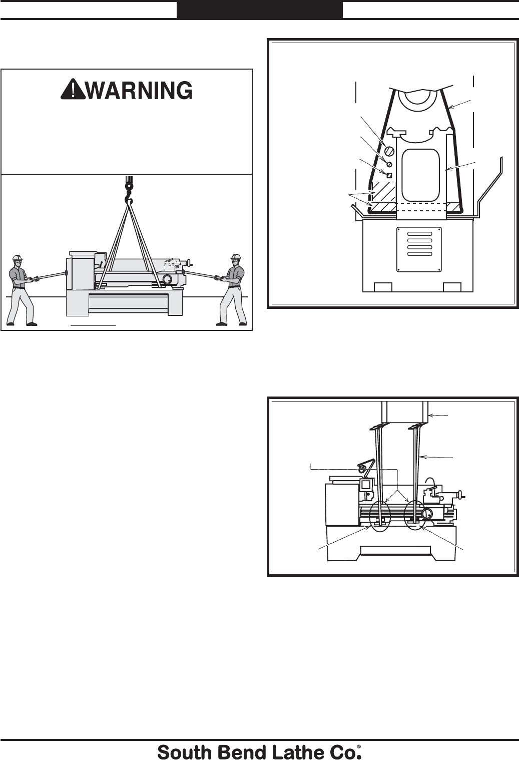
Lathe
Electrical
Access Door = Power Connection Location
131"
Min. 30"
Wall
Keep
Workpiece
Loading Area
Unobstructed
62"
147"
18"
Figure 8. Space required for full range of movement.
Physical Environment
Electrical Installation
Lighting
Weight Load
Space Allocation
Weight Load
Refer to the Machine Specifications for the
weight of your machine. Make sure that the
surface upon which the machine is placed will
bear the weight of the machine, additional
equipment that may be installed on the machine,
and the heaviest workpiece that will be used.
Additionally, consider the weight of the operator
and any dynamic loading that may occur when
operating the machine.
Space Allocation
Consider the largest size of workpiece that will
be processed through this machine and provide
enough space around the machine for adequate
operator material handling or the installation
of auxiliary equipment. With permanent
installations, leave enough space around
the machine to open or remove doors/covers
as required by the maintenance and service
described in this manual.
Physical Environment
The physical environment where your machine
is operated is important for safe operation and
longevity of parts. For best results, operate this
machine in a dry environment that is free from
excessive moisture, hazardous or flammable
chemicals, airborne abrasives, or extreme
conditions. Extreme conditions for this type
of machinery are generally those where the
ambient temperature is outside the range of 41°–
104°F; the relative humidity is outside the range
of 20–95% (non-condensing); or the environment
is subject to vibration, shocks, or bumps.
Electrical Installation
Place this machine near an existing power
source. Make sure all power cords are protected
from traffic, material handling, moisture,
chemicals, or other hazards. Make sure to leave
access to a means of disconnecting the power
source or engaging a lockout/tagout device.
Lighting
Lighting around the machine must be adequate
enough that operations can be performed
safely. Shadows, glare, or strobe effects that
may distract or impede the operator must be
eliminated.
Children or untrained
people may be seriously
injured by this machine.
Only install in an access
restricted location.
Location
For Machines Mfg. Since 7/09 Model SB1016/SB1036
-21-
PREPARATION
Lifting & Moving
Do not attempt to lift or move this lathe if you do
not have the proper equipment or the necessary
assistance from other people. All lifting
equipment must be rated for at least 10,000 lbs.
to account for dynamic loads from bouncing or
pulling that may be applied while lifting. Refer to
the Things You'll Need section on Page 14 for
details.
To lift and move your lathe:
1. Prepare the permanent location for the lathe,
and remove the top and sides of the shipping
crate, then remove the small components
from the shipping pallet.
2. To balance the lifting load, slide the tailstock
and the carriage to the far right end of the
lathe away from the headstock.
3. Position hardwood blocking under each end
of the bed as shown in Figure 9 to keep the
lifting straps away from the leadscrew, feed
rod, and control rod to prevent bending the
rods.
This machine and its parts are heavy! Serious
personal injury may occur if safe moving
methods are not used. To reduce the risk of a
lifting or dropping injury, ask others for help,
and use power equipment and guide rods.
Lifting
Strap
Lathe
Bed
Leadscrew
Feed Rod
Control
Rod
To Forklift or Lifting Hook
(Loooking at Lifting Setup from Tailstock End)
Hardwood Blocks
and Planks
Positioned as
Required to
Prevent Lifting
Straps from
Bending
Leadscrew
Figure 9. Lifting setup to keep straps from bending
leadscrew or rods.
4. Attach the lifting straps to a forklift or an
overhead crane, as shown in Figure 10, and
unbolt the lathe from the pallet.
Forklift or
Overhead
Hoist Fixture
Lifting
Straps
Use Blocks as Necessary
to Space Straps Away
from Control Rod,
Feed Rod, and Leadscrew
to Prevent Bending when
the Lathe is Lifted
Hardwood
Blocking Hardwood
Blocking
Figure 10. Lathe set up for typical lifting.
5. At each end of the lathe, have an assistant
connect a guide rod to safely keep the lathe
from swaying during lifting and transport.
6. Raise the lathe a couple of inches and place
the lathe. If lathe balance is questionable
however, or any other problem is suspected,
lower the lathe and correct the problem.
-22-
For Machines Mfg. Since 7/09
Model SB1016/SB1036 PREPARATION
Leveling & Mounting
You must level your machine and either use the
included foot pads and leveling hardware or bolt
your lathe to the floor. Because mounting your
lathe to the floor with permanent hardware is an
optional step and floor materials may vary, floor
mounting hardware is not included.
Leveling
Leveling machinery helps precision components,
such as bedways, remain straight and flat during
the lifespan of the machine. Components on an
un leveled machine may slowly twist due to the
dynamic loads placed on the machine during
operation.
For best results, use a precision level that
is at least 12" long and sensitive enough to
show a distinct movement when a 0.003" shim
(approximately the thickness of one sheet of
standard newspaper) is placed under one end of
the level.
See the figure below for an example of a high
precision level.
For accurate turning results and to prevent
warping the cast iron bed and ways, the lathe
bedways MUST be leveled from side-to-side
and from front-to-back.
Re-check the bedways 24 hours after
installation, two weeks after that, and then
annually to make sure they remain level.
Figure 11. Example of a precision level.
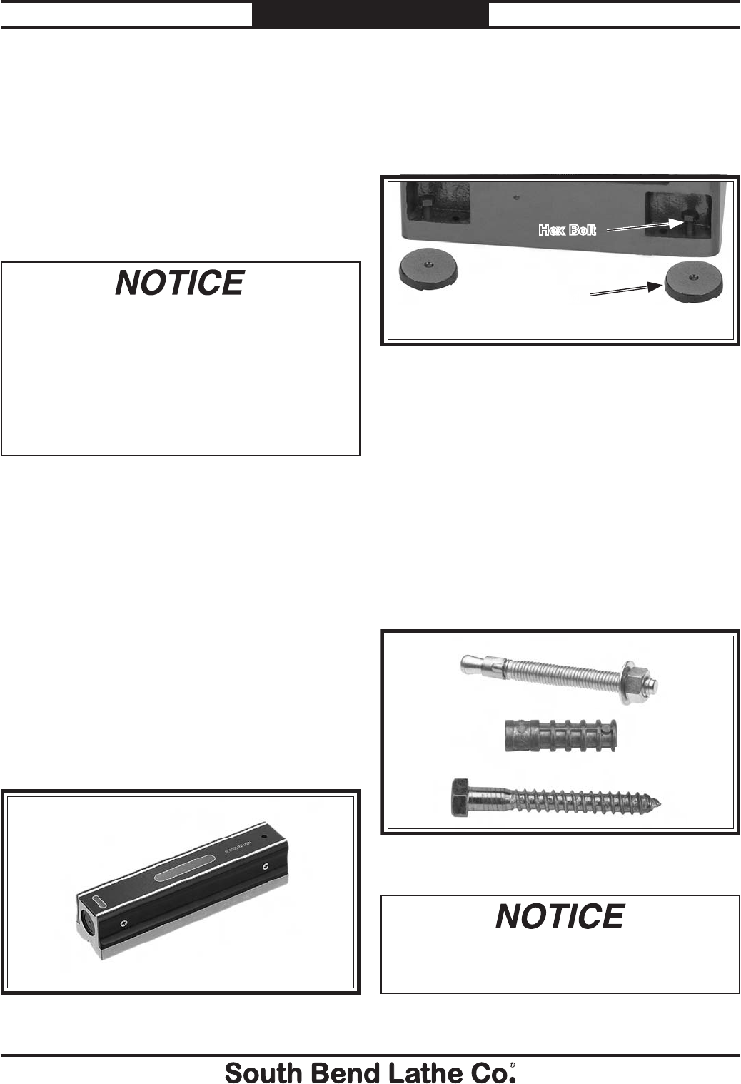
To level the machine, use a precision level to
make sure the bedways are level from side-to-
side and from front-to-back. If using the included
leveling pads (Figure 12), place them under
the six leveling bolt locations, then use a 24mm
wrench to adjust the bolts and level the lathe.
If using mounting hardware that does not allow
for adjustment, level the lathe by placing metal
shims between the lathe base and the floor before
bolting down.
Figure 12. Leveling pads and hex bolts.
Pad
Bolting to Concrete Floors
Lag Screw
and Anchor
Anchor
Stud
Lag screws and anchors, or anchor studs
(below), are two popular methods for securing
machinery to a concrete floor. We suggest you
research the many options and methods for
securing your machine and choose the best one
for your specific application.
Figure 13. Common types of fasteners for bolting
machinery to concrete floors.
Most electrical codes require that machines
connected to the power source by fixed
conduit MUST be secured to the floor.
Hex Bolt
Anchor and
Lag Screw
Anchor
Stud
For Machines Mfg. Since 7/09 Model SB1016/SB1036
-23-
PREPARATION
Assembly
With the exception of the handwheel handles, the
lathe is shipped fully assembled.
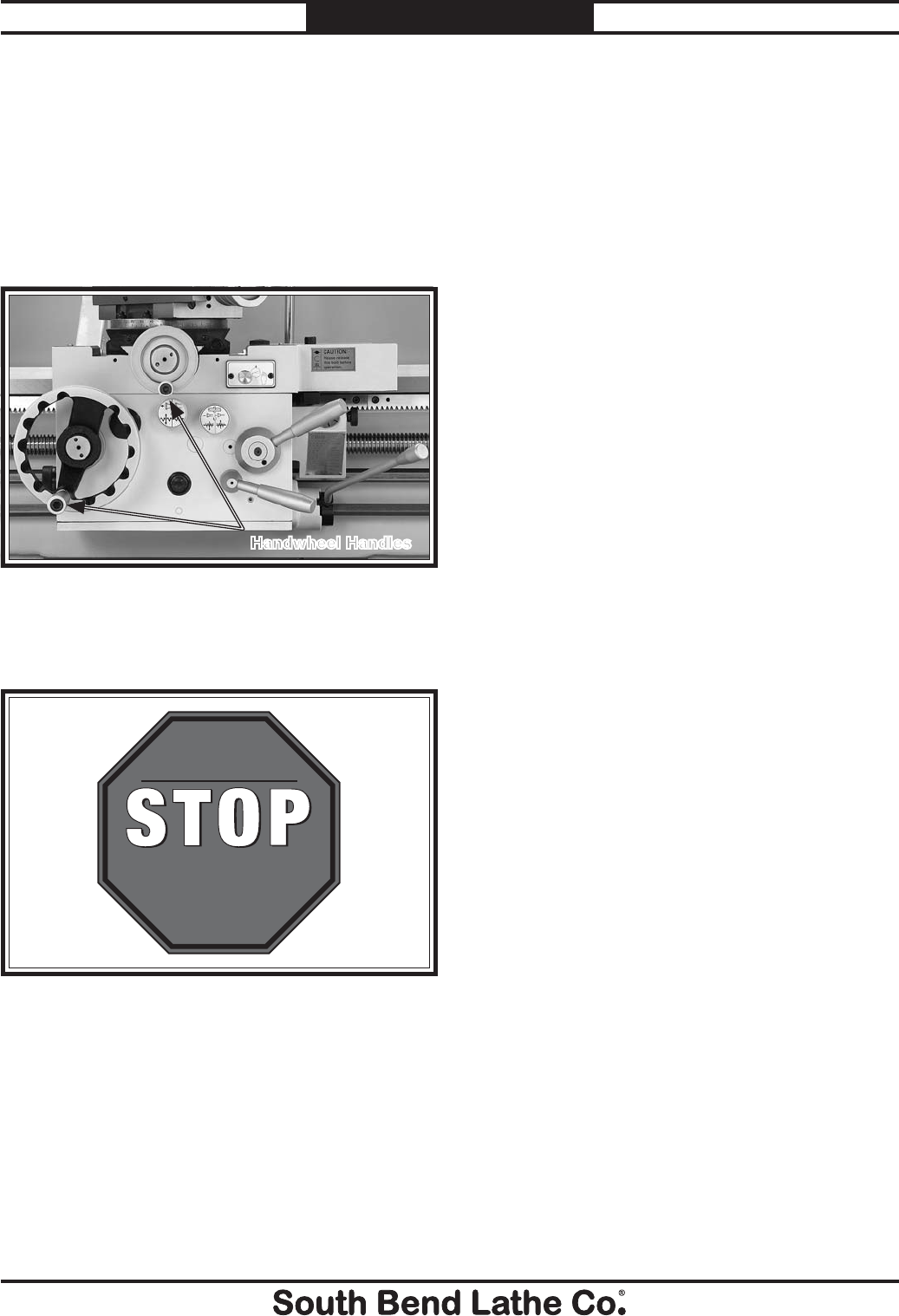
To install the handwheel handles, thread the
large handle into the carriage handwheel and the
small handle into the cross slide handwheel, as
shown in Figure 14.
Figure 14. Handwheel handles installed.
Handwheel Handles
In addition to the gearboxes, we also recommend
that you lubricate all other points on the
machine at this time. This can be accomplished
by following the maintenance schedule on Page
64.
Note: If your lathe was shipped with oil in the
gearboxes, do not change that oil until after the
break-in period.
Lubricating Lathe
GEARBOXES MUST
BE FILLED WITH OIL!
NO OIL SHIPPED WITH
MACHINE!
Refer to the Lubrication
Section in this Manual
for Recommended
Oil Type.
Adding Cutting Fluid
Add the cutting fluid of your choice now. For
detailed instructions on where the cutting fluid
tank is located and how to add fluid, refer to
Cutting Fluid System on Page 73.
The headstock oil pump tank, gearbox, and apron
must have the proper amount and type of oil in
them before the lathe can be operated for the
first time.
Running the lathe without the required oil will
void the warranty. Refer to the Lubrication
section, beginning on Page 66, for details on how
to check and add oil.
-24-
For Machines Mfg. Since 7/09
Model SB1016/SB1036 PREPARATION
Connecting to Power
Due to the complexity required for planning,
bending, and installing the conduit necessary for
a code-compliant hardwire setup, an electrician
or other qualified person MUST perform this
type of installation. Hardwire setups typically
require power supply wires to be enclosed inside
of a solid or flexible conduit, which is securely
mounted at both ends with the appropriate
conduit fittings. All work must adhere to the
required electrical codes.
The hardwire setup for this machine must
include a locking disconnect switch (see Figure
15) between the power source and the machine.
This switch serves as the means to completely
disconnect the machine from power to prevent
electrocution accidental startup during
adjustments, maintenance, or service to the
machine.
Power Source
Locking
Disconnect Switch Machine
Conduit Conduit
Figure 15. Typical hardwire setup with a locking
disconnect switch.
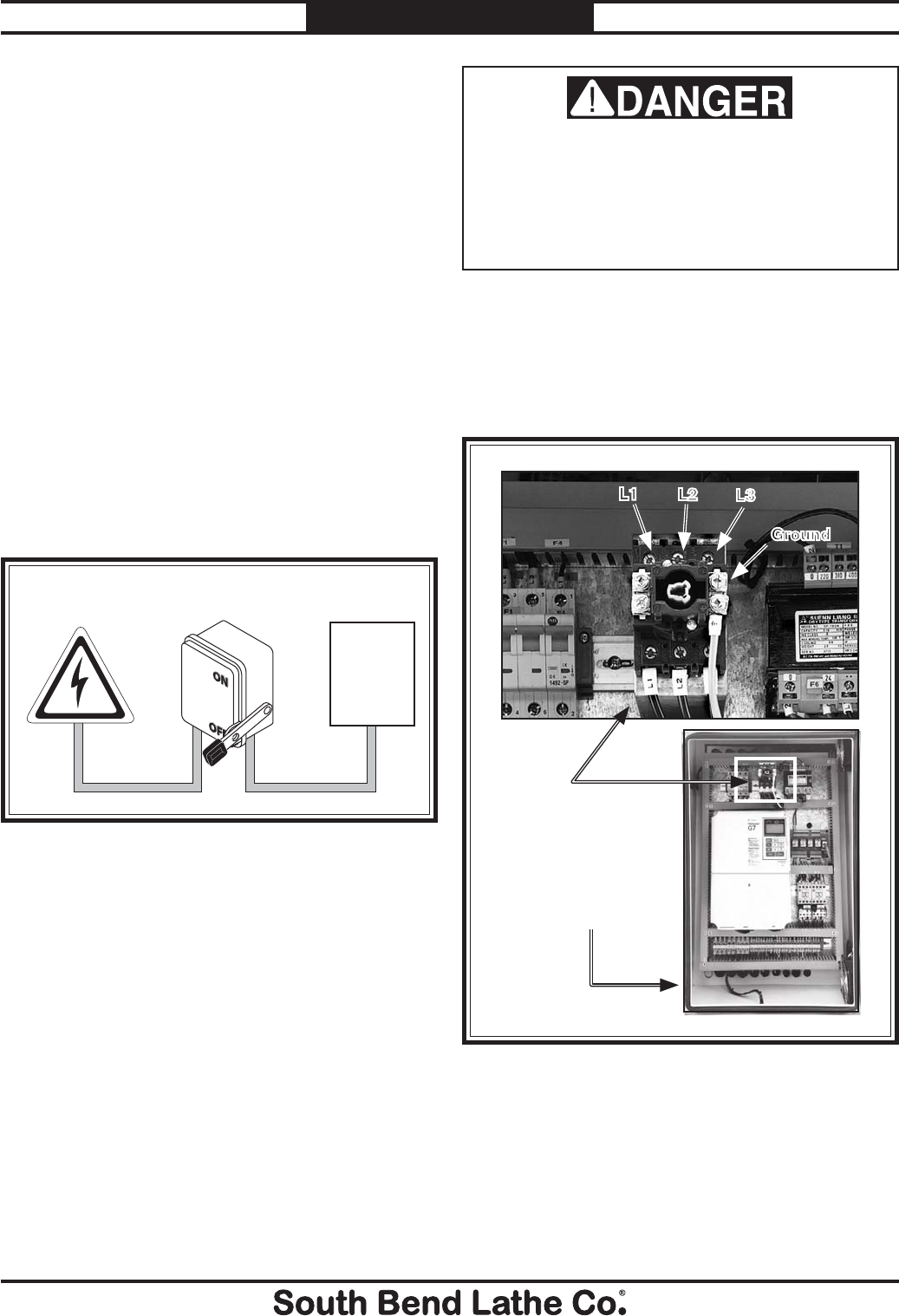
The incoming power wires must be connected to
the three terminals on the master power switch
marked L1, L2, and L3, and the incoming ground
wire must be connected the ground terminal
shown in Figure 16. All wires must have
adequate slack and be clear of sharp objects.
Electrocution or death will occur if this
procedure is attempted with live power supply
wires. All wiring going to the machine must be
disconnected from the power source, and the
power supply shut OFF and locked out before
performing this procedure.
When the wiring job is complete, close and lock
the main electrical box door, otherwise the
machine control panel will be disabled.
Figure 16. Machine power connection locations.
Master
Power
Switch
Pre-drilled Hole
for Incoming
Power
L1 L2 L3
Ground
For Machines Mfg. Since 7/09 Model SB1016/SB1036
-25-
PREPARATION
Test Run
After all preparation steps have been completed,
the machine and its safety features must be
tested to ensure correct operation. If you discover
a problem with the operation of the machine or
its safety components, shut the machine down,
disconnect it from power, and do not operate it
again until you have resolved the problem.
Note: The variable speed on this machine
is controlled by a frequency drive unit with
sensitive electronics. These electronics can
be damaged if power is disconnected during
operation. Therefore, unless the stop button and
brake lose functionality, always properly shut
the machine down before, disconnecting it from
the power source.
A Troubleshooting section is provided,
starting on Page 88, to assist you with
solutions if a problem occurs or if the lathe
does not function as described in this section.
If you need additional help after reviewing the
troubleshooting section, or you are not confident
troubleshooting the machine on your own,
contact our tech support at (360) 734-1540.
To test run your machine:
1. Read and follow the safety instructions at
the beginning of the manual, take required
safety precautions, and complete all previous
preparation steps including verifying that all
oil levels are correct.
2. Clear away all tools and objects used during
assembly, lubrication, and preparation.
3. DISCONNECT LATHE FROM POWER!
4. Make sure that the chuck and jaws, if
installed, are secure (refer to Chuck and
Faceplate Mounting on Page 35).
Note: If a chuck is not installed on the lathe, you
do not need to install one for this test.
5. Push the stop button in, turn the spindle
speed dial to the minimum, and turn the
cutting fluid pump switch (Figure 17) to the
OFF position, and point the nozzle into the
chip pan.
Figure 17. Control panel.
Stop ButtonPump Switch
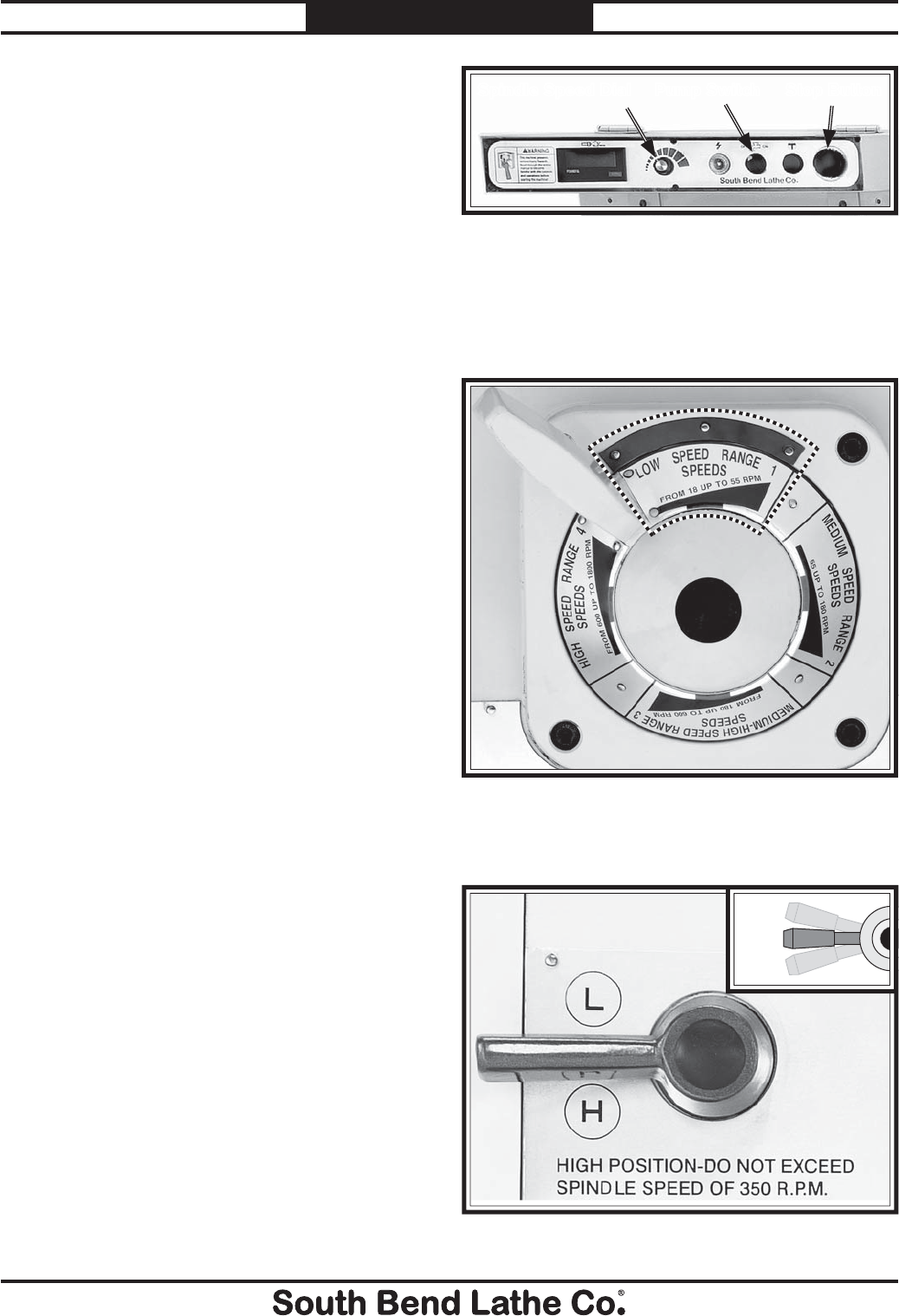
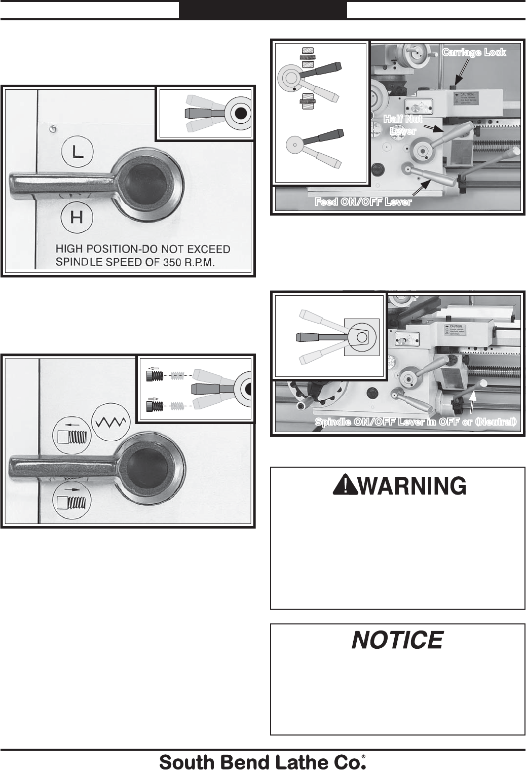
6. Move the spindle range lever (Figure 18) to
low speed range 1 (18-55 RPM).
Note: You may need to slightly rotate the chuck
by hand to engage the lever.
Spindle Speed Dial
Figure 19. Gearbox range lever in neutral.
7. Move the gearbox range lever to the middle
(neutral) position, as shown in Figure 19.
Figure 18. Spindle range lever.
LOW
Neutral
HIGH
-26-
For Machines Mfg. Since 7/09
Model SB1016/SB1036 PREPARATION
8. Move the headstock feed direction lever to
the (neutral) position (see Figure 20).
Figure 20. Feed direction lever in neutral.
9. Pull up on the half nut and the feed levers to
disengage the carriage, as shown in Figure
21, and make sure the carriage lock is loose.
Figure 21. Halfnut and carriage feed levers moved to
the disengaged positions.
Carriage Lock
Half Nut
Lever
10. Swing the spindle ON/OFF lever outward
and move it to the OFF (center) position, as
shown in Figure 22.
Figure 22. Spindle ON/OFF lever in OFF (Neutral).
Spindle
ON/OFF
Lever in OFF
or (Neutral)
FORWARD
REVERSE
NEUTRAL
Engaged
Disengaged
Engaged
Disengaged
11. Make sure that the master power switch is
OFF, shown in Figure 23. Next, connect
the lathe to the power source, and turn the
master power switch ON.
Figure 23. Master power switch in ON position.
Master
Power
Switch
12. Rotate the stop button shown in Figure 24
clockwise until it pops out. The headstock oil
pump will turn ON.
Never bypass the oil pressure safety switch!
If you do, you will void the warranty, and
headstock damage may occur.
Figure 24. Stop button.
Stop Button
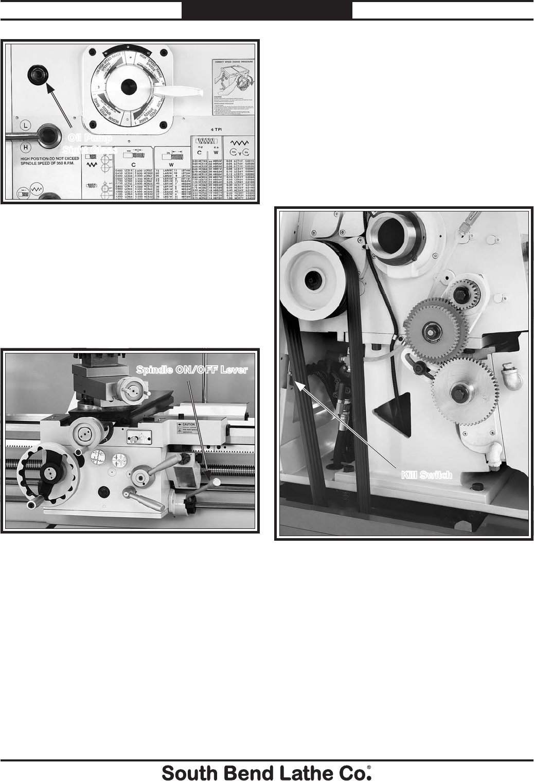
13. Observe the oil pump tube through the sight
glass (Figure 25). Verify that you see oil
flowing.
Note: This headstock has a pressurized oil
system that is equipped with an oil pressure
safety switch. If oil stops flowing or does not
flow to start with, the lathe will not operate
until the oil is properly flowing. Refer to
Troubleshooting to correct.
Feed ON/OFF Lever
For Machines Mfg. Since 7/09 Model SB1016/SB1036
-27-
PREPARATION
14. Make sure that all bystanders are out of the
way, tools are cleared away, and the chuck
key is removed from the chuck.
15. Move the spindle ON/OFF lever (Figure
26) down and the chuck will rotate counter-
clockwise (down and toward you, as you face
the front of the lathe).
Figure 25. Oil pump sight glass.
Oil Pump
Sight Glass
Figure 26. Starting the lathe.
16. Observe the lathe and listen for any
abnormal noises or vibration. The lathe
should run smoothly. If the spindle rotates in
the incorrect direction, refer to Correcting
Phase Polarity on Page 16 to solve the
problem.
17. Push the stop button. The lathe should stop.
18. Move the spindle ON/OFF lever up to the
OFF position, reset the stop button by
twisting it clockwise until it pops out, then
restart the spindle with the lever.
19. Push the foot brake. The lathe should come
to a quick stop.
— If the foot brake has no effect on the lathe,
push the stop button, and refer to V-Belts
and Brake & Switch on Page 81 to
make any required adjustments.
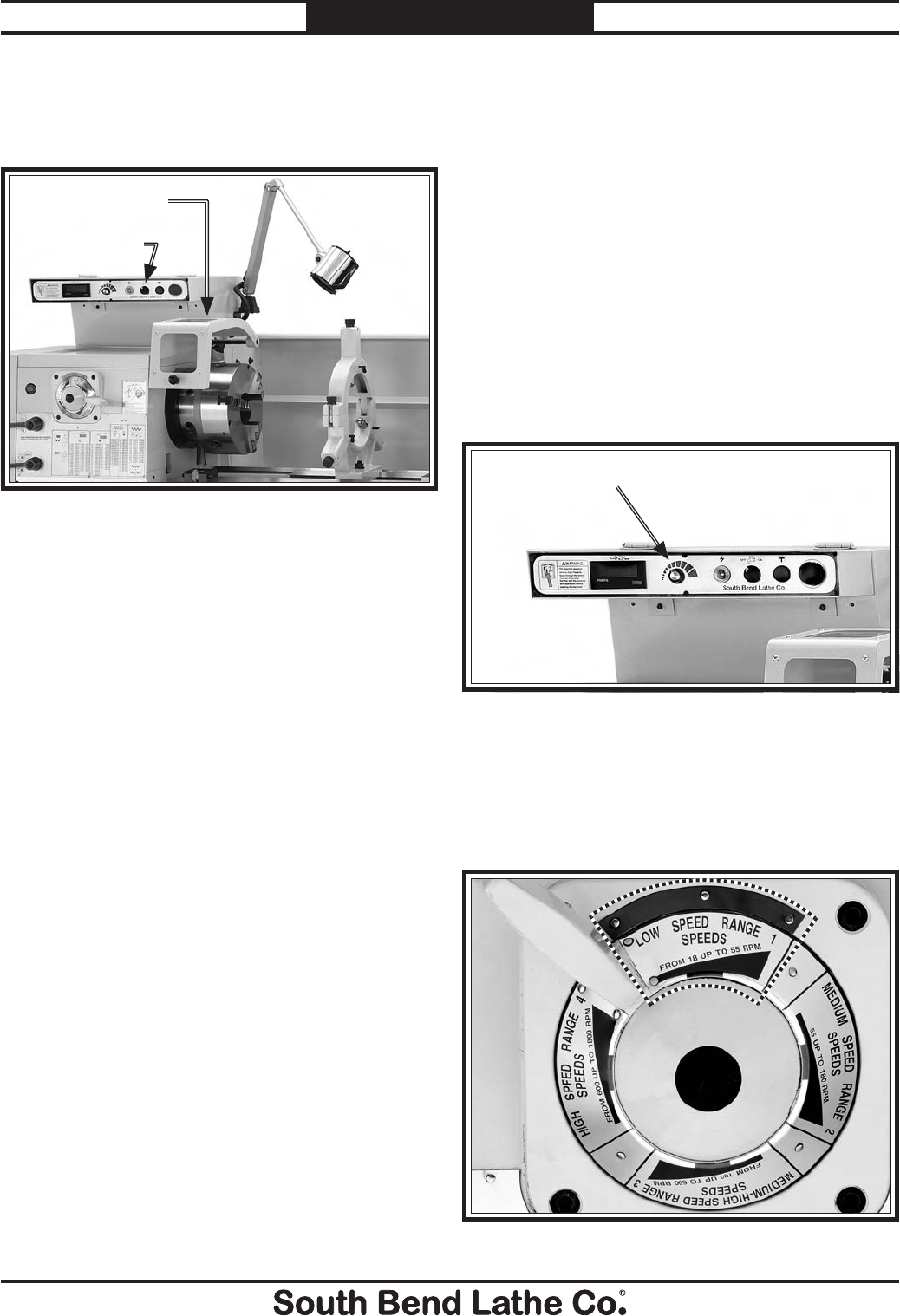
20. Remove the lathe headstock side cover.
The kill switch shown in Figure 27 should
prevent the lathe from starting while this
cover is removed.
21. Stand away from all the exposed gears on
the side of the headstock, and attempt to
start the lathe.
— If the lathe starts, the safety switch is not
functioning properly and may need to be
replaced before the machine can be safely
operated.
22. Reinstall the end gear cover, then start the
lathe.
Figure 27. Headstock gear cover kill switch.
Kill Switch
Spindle ON/OFF Lever
-28-
For Machines Mfg. Since 7/09
Model SB1016/SB1036 PREPARATION
23. Lift the chuck guard shown in Figure 28,
and try to start the lathe again. The cover
kill switch should prevent the lathe from
starting while the guard is open.
Figure 28. Chuck safety cover.
24. Close the chuck guard.
25. Open the cutting fluid valve, and using the
pump switch shown in Figure 28, turn the
cutting fluid pump ON. Verify that fluid
flows from the nozzle, then turn the cutting
fluid pump OFF.
— If no fluid is pumped, but fluid level is
full, no hose kinks exist, and the cutting
fluid nozzle is open, the pump may be
wired with incorrect phase polarity.
Correct the pump phase polarity wiring as
outlined on Page 16.
The test run is now finished. Shut the lathe down
and begin the Spindle Break-In procedure.
Cutting Fluid
Pump Switch
Chuck Guard
Spindle Break-In
It is essential to closely follow the proper break-in
procedures to ensure trouble-free performance.
Complete this process once you have familiarized
yourself with all instructions in this manual and
completed the test run.
To complete the spindle break-in:
1. Make sure you have completed the Test
Run procedure beginning on Page 25.
2. Turn the spindle speed dial (Figure 29) all
the way counterclockwise to the minimum
speed.
Figure 29. Spindle speed dial.
Spindle Speed Dial
3. Move the spindle range lever (Figure 30) to
low speed range 1 (18-55 RPM).
Note: You may need to slightly rotate the chuck
by hand to engage the lever.
Figure 30. Spindle range lever in low 1.
For Machines Mfg. Since 7/09 Model SB1016/SB1036
-29-
PREPARATION
4. Move the quick change range lever to the
middle (neutral) position, as shown in
Figure 31.
Figure 31. Quick change gearbox in neutral position.
5. If you have not already done so, move the
headstock feed direction lever to the central
or neutral position as shown in Figure 32
Figure 32. Feed direction lever in neutral position.
FORWARD
REVERSE
NEUTRAL
LOW
Neutral
HIGH
6. Pull up on the half nut and the feed levers to
disengage the carriage, as shown in Figure
33, and make sure the carriage lock is loose.
Carriage Lock
Half Nut
Lever
Engaged
Disengaged
Engaged
Disengaged
Figure 33. Halfnut and carriage feed levers shown in
the disengaged positions.
7. Move the spindle ON/OFF lever to the OFF
(center) position, as shown in Figure 34.
Figure 34. Spindle ON/OFF lever in OFF (Neutral).
Do not leave the lathe unattended during
the break-in period. Should any problem
arise, you must be able to immediately shut
down the lathe to avoid damage. Curious
bystanders can also be entangled with a
lathe chuck if the machine is left running
and unattended. Entanglement can lead to
immediate amputation or death.
Reverse
Off
Forward
Spindle ON/OFF Lever in OFF or (Neutral)
After the first 16 hours of use, the V-belts will
stretch and seat into the pulley grooves. The
V-belts must be properly re-tensioned after
this period to avoid reducing their useful life.
Refer to the V-Belts section on Page 81 for
detailed instructions.
Feed ON/OFF Lever
-30-
For Machines Mfg. Since 7/09
Model SB1016/SB1036 PREPARATION
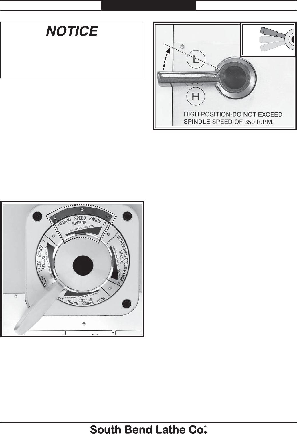
NEVER attempt to shift the headstock or
quick change gearbox when the lathe is in
operation. Gear clash causing tooth damage
will result. Only use the gear shifting levers
when the spindle id stopped.
8. Turn the lathe ON.
9. Using the speed dial on the control panel,
and the spindle range lever on the headstock,
run the lathe spindle for ten minutes at 55,
180, 600, and 1800 RPM as indicated by the
tachometer on the control panel.
10. When complete, reverse spindle rotation
and run lathe in reverse at 1800 RPM for 10
minutes.
11. After completing Step 10, stop the lathe,
set the spindle range lever to medium speed
range 2 as shown in Figure 35.
Figure 35. Spindle range lever in medium 2.
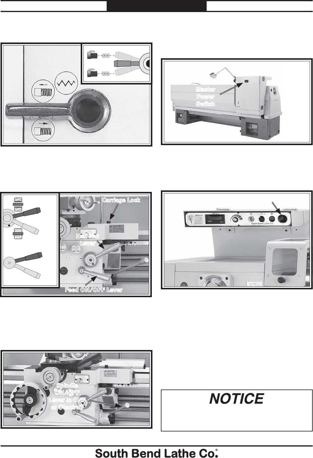
12. Move the quick change range lever shown in
Figure 36 to L or the low range position.
For your convenience, the adjustments listed
below have been performed at the factory.
However, because of the many variables involved
with shipping, we recommend that you at least
verify the following adjustments to ensure the
best possible results from your new machine.
Step-by-step instructions for these adjustments
can be found on the pages referenced below.
Factory adjustments that should be verified:
s 4AILSTOCKALIGNMENTPage 44).
s #OMPOUNDANDCROSSSLIDEBACKLASH
adjustment (Page 77).
s 'IBADJUSTMENTSPage 78).
Recommended
Adjustments
13. Turn the lathe ON, and run the lathe at 180
RPM for 10 minutes with the quick change
gearbox in low, and then another 10 minutes
with the quick change gearbox in high.
14. When complete, while the oil is still warm
and any metal particles are still suspended
in the oil, change the oil in the quick change
gearbox and the headstock oil pump tank
immediately.
15. Tighten the V-belts, and perform all
other lubrication steps mentioned in the
Maintenance section of this manual.
Figure 36. Quick change range lever.
LOW
Neutral
HIGH
OPERATION
For Machines Mfg. Since 7/09 Model SB1016/SB1036
-31-
OPERATION
Operation Overview
Loose hair, clothing, or
jewelry could get caught
in machinery and cause
serious injury or death.
Keep these items away
from moving parts at all
times to reduce this risk.
During operation, small
metal chips may become
airborne, leading to serious
eye injury. Wear safety
glasses to reduce this risk.
To complete a typical operation, the operator
does the following:
1. Puts on safety glasses, rolls up sleeves,
removes jewelry, and secures any clothing,
jewelry, or hair that could get entangled in
moving parts.
2. Examines the workpiece to make sure it
is suitable for turning, then mounts the
workpiece in one of the chucks or on the
faceplate, and removes the chuck key from
the chuck.
3. Mounts the tooling, aligns it with the
workpiece, then backs it away to establish a
safe startup clearance.
4. Clears all tools from the lathe.
5. Sets the correct spindle speed range for the
operation, and turns the spindle speed dial
all the way counterclockwise (to the lowest
speed) to avoid the possibility of damage
from a high speed start.
6. Checks for safe clearances by rotating
the workpiece by hand at least one full
revolution.
7. Moves slides to where they will be used
during operation.
8. If using power feed, selects the proper feed
rate for the operation.
9. Turns the master power switch ON, resets
the stop button so it pops out, then moves
the spindle ON/OFF lever down to start
spindle rotation. The spindle will rotate
forward (the top of the chuck rotates toward
the operator).
10. Turns the spindle speed dial clockwise to the
desired RPM.
11. Uses the carriage handwheels or power
feed options to move the tooling into the
workpiece for operations.
12. When finished cutting, moves the ON/OFF
lever to the center position to turn the lathe
OFF, then removes the workpiece.
To reduce the risk of
serious injury when using
this machine, read and
understand this entire
manual before beginning
any operations.
The purpose of this overview is to provide
the novice machine operator with a basic
understanding of how the machine is used durin
g
operation, so they can more easily understand
the controls discussed later in this manual.
Note: Due to the generic nature of this overview,
it is not intended to be an instructional guide
for performing actual machine operations.
To learn more about specific operations and
machining techniques, seek training from people
experienced with this type of machine, and do
additional research outside of this manual by
reading "how-to" books, trade magazines, or
websites.
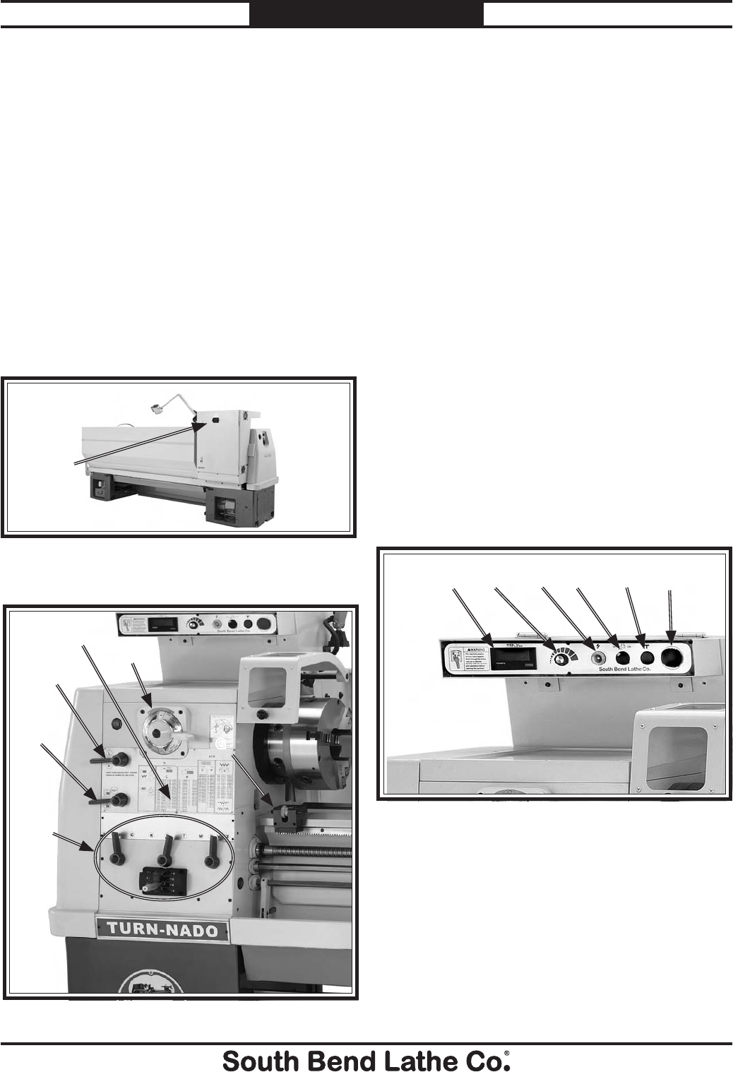
-32-
For Machines Mfg. Since 7/09
Model SB1016/SB1036 OPERATION
Refer to the following figures and descriptions to
learn about the basic controls of this machine.
Main Power Control
A. Master Power Switch: The rotary switch
shown in Figure 37 toggles incoming power
ON/OFF to the lathe. It also prevents the
electrical box door from being opened when
the switch is ON. If switched to OFF, this
switch is not a safe alternative to completely
disconnecting the machine from power when
wiring, servicing, or making repairs.
B. Quick Change Gearbox Levers: Controls the
leadscrew and feedrod speed for threading
and feed operations.
C. Headstock Feed Direction Lever: Controls
the direction that the leadscrew and feed rod
rotate.
D. Gearbox Range Lever: Shifts the quick
change gearbox from neutral into high or
low.
E. Threading and Feed Chart: Shows the
configurations of the gearbox levers and
displays the positions of the various gears for
different threading or turning options.
F. Spindle Speed Range Lever: Controls the
speed ranges available to the spindle.
G. Micrometer Stop: Clamps along the way, and
serves as a stopping point indicator, so when
cutting shoulders the tool tip can be stopped
at exactly the same point every time.
Headstock Controls
B
Figure 38. Headstock controls.
Description of Controls
& Components
C
D
E
F
G
Control Panel
Figure 39. Control panel.
MLKJIH
H. Tachometer Display: Displays the current
spindle speed in RPM.
I. Spindle Speed Dial: When rotated, the EVS
dial electronically varies the spindle speed
within each of the four available spindle
speed ranges.
J. Power Light: Illuminates when lathe is
receiving power and the controls are LIVE.
A
Figure 37. Master power switch.
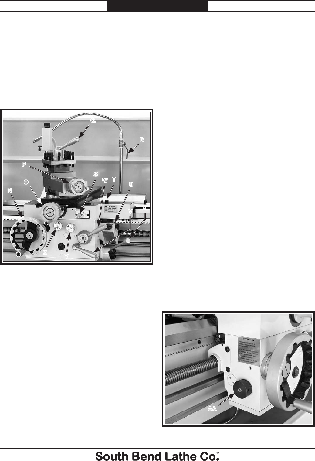
For Machines Mfg. Since 7/09 Model SB1016/SB1036
-33-
OPERATION
K. Cutting Fluid Pump Switch: Start/stops the
cutting fluid pump motor.
L. Jog Button: Turns the spindle motor ON
while being pressed and held.
M. Stop Button: Stops all machine functions.
Twist clockwise to reset.
N. Carriage Handwheel: Moves the carriage
parallel along the ways, and can be
disengaged when power feed operations
would make it an entanglement hazard.
O. Cross Slide Handwheel: Moves the cross
slide perpendicular to the ways into the
workpiece.
P. Compound Slide Handwheel: Moves the tool
in fine increments at compound angles.
Q . 4-Position Tool Post Lever: Locks the rotary
tool post in four possible detents.
R. Flow Control Lever: Controls the flow of
cutting fluid from the nozzle.
Carriage Controls
N
P
Figure 40. Carriage controls.
O
Q
TU
R
S
W
V
Y
Z
X
S. Way Oil Oil Pump: Draws oil from the apron
case and lubricates the carriage and ways
through various oil ports.
T. Carriage Lock: Secures the carriage in place
for greater rigidity and accuracy when
using the cross or compound slide for the
machining operation.
U. Thread Dial and Chart: Dial indicates when
to engage the half nut during threading
operations. Chart indicates on which thread
dial reading to engage the half nut for
specific inch or Whitworth thread pitches.
V. Feed ON/OFF Lever: Engages and
disengages the longitudinal and cross feed
system at the apron.
W. Half Nut Lever: Engages and disengages the
half nut for threading operations.
X. Spindle ON/OFF Lever: Starts, stops and
reverses direction of spindle rotation.
Y. Apron Feed Direction Knob: Changes
direction of carriage feed or the cross slide
feed without having to stop the lathe and
move the headstock feed direction lever.
Z. Feed Selection Knob: Selects either the
carriage feed or the cross slide feed.
AA. Feed Clutch: This adjustable clutch helps
protect the feed system against broken gears
and shafts caused by accidental overloads.
Figure 41. Adjustable feed clutch.
AA
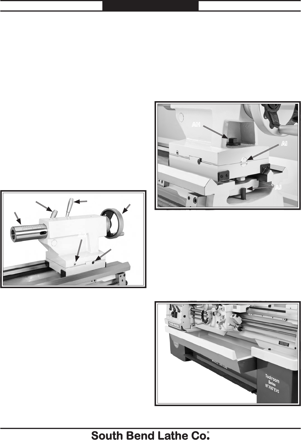
-34-
For Machines Mfg. Since 7/09
Model SB1016/SB1036 OPERATION
AH. Tailstock Lock Bolt: Tightens a secondary
tailstock clamp to assist the primary
tailstock lock lever and clamp.
AI. Offset Scale: Indicates the distance of
tailstock offset from the spindle centerline
with arbitrary marks.
AJ. Tailstock Stop Pin: Prevents the tailstock
from sliding off of the ways.
Figure 43. Tailstock controls.
AH
AI
AJ
Tailstock Controls
AB. Quill: The quill has an MT#5 bore, metric
and inch scale, and drift slot to remove tight-
fitting tooling.
AC. Quill Lock Lever: Locks the quill in position.
AD. Tailstock Lock Lever: Secures the tailstock in
place along the bedway.
AE. Handwheel: Moves the quill toward or away
from the spindle, and is quipped with a
graduated collar divided in increments of
0.001" where 360°= 0.200".
AF. Gib Screws: Adjust a tapered gib to control
tailstock sliding accuracy.
AG. Tailstock Offset Screws: Adjusts the
tailstock offset left or right from the spindle
centerline.
AF
AG
AB
AC AE
Figure 42. Tailstock controls.
AD
Chip Drawer
The chip drawer shown in Figure 44 catches
cutting fluid and metal chips during the
machining process. It slides open for easy
cleaning.
Also, the chip drawer contains a screen that
allows runoff cutting fluid to drain back into the
cutting fluid tank.
Figure 44. Chip drawer.
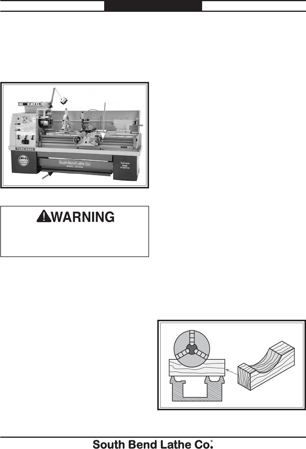
For Machines Mfg. Since 7/09 Model SB1016/SB1036
-35-
OPERATION
Foot Brake
This lathe is equipped with a foot brake (Figure
45) to quickly stop the spindle. Pushing the foot
brake while the spindle is ON cuts power to the
motor and stops the spindle. Once stopped, the
spindle lever MUST be returned to the neutral
position before the spindle can be restarted.
Figure 45. Foot brake and spindle ON/OFF lever.
Foot Brake
Spindle ON/OFF Lever
Using the foot brake to stop the lathe reduces
risk of an entanglement injury from allowing
the lathe to coast to a stop. Use the foot brake
to stop the lathe whenever possible.
Chuck & Faceplate
Mounting
This lathe is shipped with the 3-jaw chuck
installed. This is a scroll-type chuck, meaning
that all three jaws move in unison when
adjusted.
The included 4-jaw chuck features independent
jaws, which are used for square or unevenly-
shaped stock, and to mount work that needs to
be adjusted to near "0" total indicated runout.
If neither chuck can hold your workpiece, the
cast-iron faceplate has slots for T-bolts that hold
standard or custom clamping hardware. With the
correct clamping hardware, this faceplate will
hold non-cylindrical parts.
The chucks and faceplate have a D1-8 camlock
system. A chuck key is used to turn the locking
cams to secure/release the chuck/faceplate.
Items Needed Qty
Dead Blow Hammer ..............................................1
Chuck Cradle or Plywood 3⁄4" (to protect bed) ...... 1
Chuck Key ............................................................. 1
Removing Chuck or Faceplate
1. DISCONNECT LATHE FROM POWER!
2. Lay a chuck cradle (see Figure 46) or
plywood under the chuck or faceplate and
over the bedway to protect the precision
ground surfaces from damage and reduce
injury if fingers get pinched.
Figure 46. Wooden chuck support cradle.
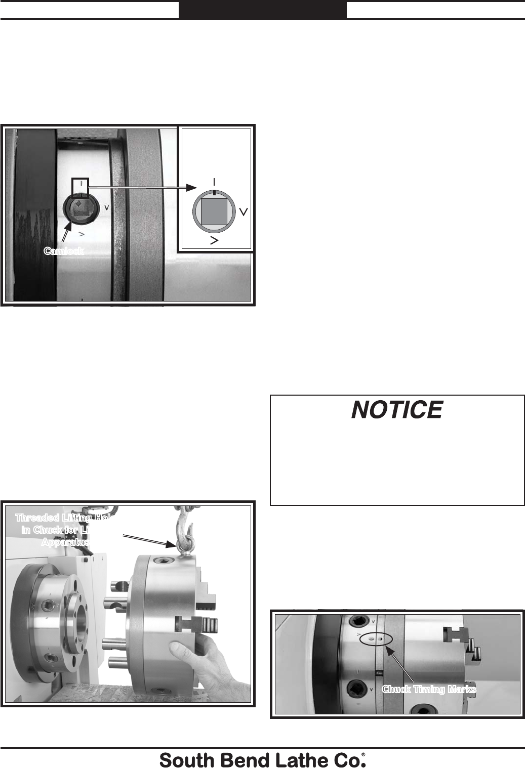
-36-
For Machines Mfg. Since 7/09
Model SB1016/SB1036 OPERATION
3. One at a time, use the chuck key to turn
each of the camlocks counterclockwise until
the cam line aligns with the cam release
datum line, as shown in Figure 47. As you
turn the camlocks, they will rise up slightly
from the spindle body.
Figure 47. Camlock loosened with the cam line aligned
with the datum line.
4. Remove the chuck key, then use a dead-
blow hammer or a wood block to lightly tap
around the circumference of the chuck or
faceplate to break it free from the spindle
taper and camlock sockets. Be sure to
support the bottom of the chuck.
5. With a rocking motion, carefully remove the
chuck or faceplate from the spindle nose, as
shown in Figure 48, making sure to support
the weight with an adequate chuck cradle.
Figure 48. Removing the 3-jaw chuck from a spindle
nose.
Threaded Lifting Hole
in Chuck for Lifting
Apparatus
Camlock
Cam Release
Datum Line
and Cam Line
Mounting Chuck or Faceplate
The 4-jaw chuck is shipped with six camlock
studs that may have to be installed before
chuck mounting. If you have not yet installed
the camlock studs, complete the instructions in
"Installing and Adjusting Camlock Studs" on
Page 37.
To mount a chuck or faceplate:
1. DISCONNECT LATHE FROM POWER!
2. Lay a chuck cradle (see Figure 46) or
plywood under the chuck or faceplate and
over the bedway to protect the precision
ground surfaces from damage and reduce
injury if fingers get pinched.
3. Clean away debris and oily substances from
the mating surfaces of the spindle and chuck
or faceplate.
4. Inspect and make sure that all camlock
studs are undamaged, are clean and lightly
oiled, and that the camlock stud cap screws
are in place and snug.
Never install a chuck or faceplate without
having the camlock cap screws in place or
fully tightened. If you ignore this notice,
the chuck may not be removable since the
camlock studs may turn with the camlocks
and never release.
5. Position the chuck/faceplate in front of the
spindle nose, align the chuck timing marks,
as shown in Figure 49, and align the cam-
lock studs with the sockets, then carefully
insert the chuck or faceplate onto the
spindle.
Figure 49. Chuck timing marks aligned.
Chuck Timing Marks
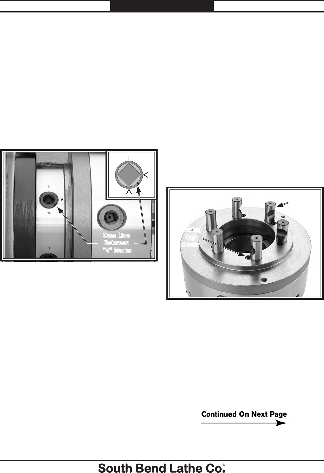
For Machines Mfg. Since 7/09 Model SB1016/SB1036
-37-
OPERATION
6. Tighten camlocks in a star pattern to draw
the chuck up evenly on all sides while
reducing chance of misalignment, and make
sure to tighten camlocks in an incremental
manner to ensure that no camlock gets fully
tightened all at once (i.e., snug the camlocks
on the first pass, then moderately tighten on
the next pass, then fully tighten on the third
pass).
As you tighten the camlocks, the chuck or
faceplate will snug up onto the spindle nose.
When fully tightened, the cam line will fall
between the two "V" marks on the spindle
nose, as shown in Figure 50.
Figure 50. Camlock fully tightened with the line
between the "V" marks.
Cam Line
Between
"V" Marks
Note: If any of the cam lines do not fall between
the "V" marks when the camlock is tight,
you must adjust the offending camlock stud
as discussed in Installing and Adjusting
Camlock Studs on Page on this page.
To make sure that the chuck centerline is
aligned with the spindle centerline, clamp a
test rod in the chuck and use a test indicator
mounted on the bedways to check for
workpiece runout.
Installing and Adjusting Camlock
Studs
Figure 51. Identifying chuck camlock studs and
locking cap screws.
Locking
Cap
Screw
Cam-Lock
Stud
When fitting a chuck or faceplate with camlock
studs, or when mounting a new chuck or
faceplate, it may be necessary to install or adjust
the camlock studs.
Tool Needed Qty
Hex Wrench 6mm .................................................1
To install or adjust camlock studs onto a
chuck or faceplate:
1. Lay the chuck or faceplate upside down on a
protective, flat surface.
2. If installed, remove the locking cap screw
adjacent to each of the six cam-lock
mounting holes (see Figure 51).
3. Thread each cam-lock stud into the chuck
or faceplate until the depth mark shown in
Figure 52 is even with the surface of the
chuck or faceplate and the curved indent
on the side of the stud faces the locking cap
screw hole, as shown in Figure 53. This is
an initial adjustment.
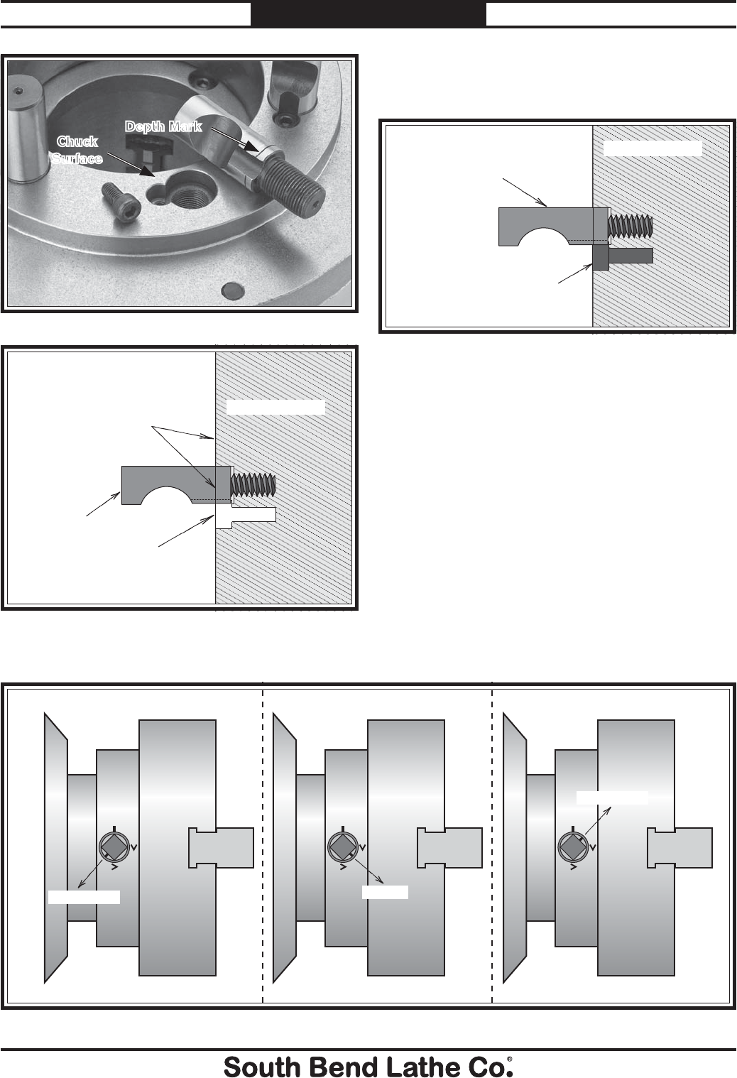
-38-
For Machines Mfg. Since 7/09
Model SB1016/SB1036 OPERATION
Camlock Stud Depth
Mark is Even with Chuck
or Faceplate Surface
Camlock Stud
Locking Cap
Screw Hole
Chuck/Faceplate
Figure 53. Initial adjustment of camlock stud.
5. Make sure that the cam-lock studs can
rotate back and forth against the head of the
locking cap screw (see Figure 54).
Camlock Stud Can
Rotate Back/Forth
Slightly
Cap Screw
Installed & Tight
Chuck/Faceplate
Figure 54. Camlock stud and cap screw correctly
installed.
6. Insert the chuck onto the spindle, then check
the position of each camlock, making sure
the cam line points between the "V" marks.
— If one or more of the cams do not point
between the "V" marks on the chuck,
remove the chuck, and fine tune the
camlock stud adjustment by adjusting the
stud in or out and using Figure 55 as a
guide to correctly position the cam lines.
7. When the camlocks and chuck fit properly,
find the existing mark on the spindle, and
mark the chuck as shown in Figure 49.
Figure 52. Example of camlock stud depth mark.
Depth Mark
Chuck
Surface
Figure 55. Correct camlock stud alignment.
Not Correct
Not Correct
Correct
4. Install and tighten the locking cap screws.
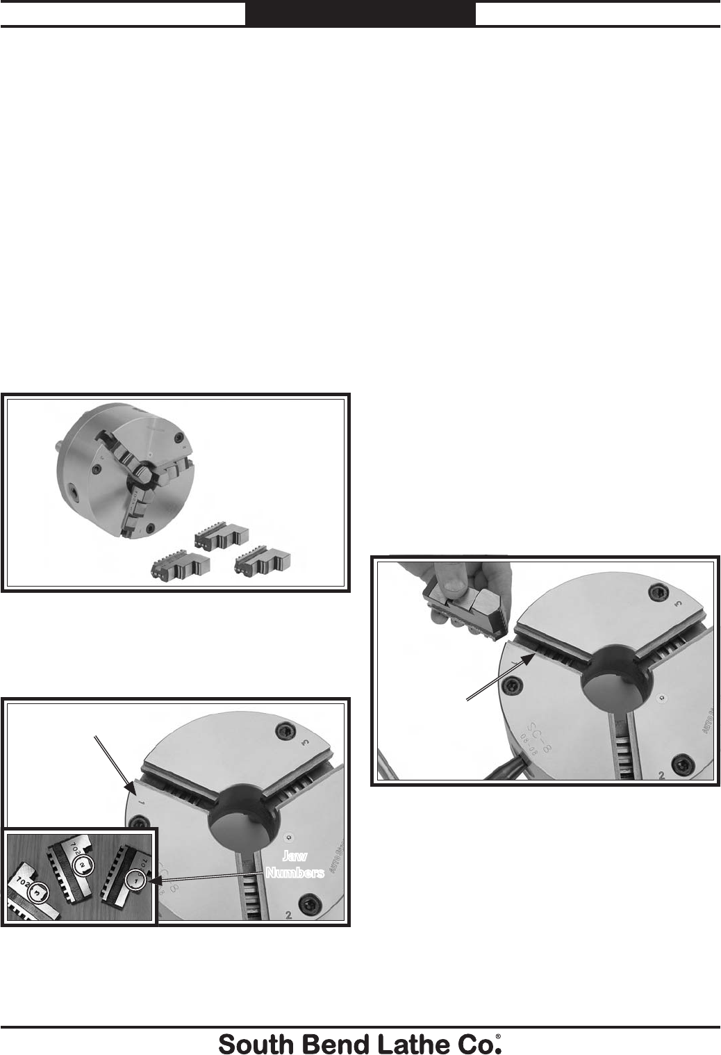
For Machines Mfg. Since 7/09 Model SB1016/SB1036
-39-
OPERATION
3-Jaw Chuck
Refer to Chuck & Faceplate Mounting
instructions on Page 35 to mount the 3-jaw
chuck to the spindle.
The 3-jaw scroll-type chuck included with this
lathe features hardened steel jaws that center the
workpiece. When the operator opens or closes the
jaws with the chuck key, the jaws move in unison.
There are two sets of removable hardened steel
jaws included with the 3-jaw chuck—inside and
outside jaws. Use the correct jaws for the size
and configuration of the workpiece to hold it
firmly and securely on the chuck (see Figure
56). The outside of the jaws are used to hold the
workpiece from the outer diameter.
Figure 56. Chuck and jaw selection.
Numbered from 1–3, the jaws must be used in
the matching numbered jaw guides, as shown in
Figure 57.
Figure 57 Jaw guides and jaw numbers.
Jaw Guide #1
Jaw
Numbers
Note: The chuck does not need to be removed
from the spindle to swap the jaws.
Changing Jaws
Item Needed Qty
Chuck Key ............................................................. 1
White Lithium Grease .......................... As Needed
Chuck Cradle or Plywood 3⁄4" (to protect bed) ...... 1
To change the jaw:
1. DISCONNECT LATHE FROM POWER!
2. Place a piece of wood over the ways to
protect them from potential damage.
3. Insert the chuck key and turn it
counterclockwise to back the jaws out and
remove them.
4. Clean the jaw mating surfaces and apply
a thin film of white lithium grease to the
mating surfaces.
5. Set the previously-mounted jaws aside in a
safe place free of moisture and abrasives.
6. Rotate the chuck key clockwise until you see
the initial thread of the scroll gear just begin
to enter jaw guide #1 (see Figure 58).
7. Insert jaw #1 into jaw guide #1 and hold the
jaw against the scroll gear lead thread.
8. Rotate the chuck key clockwise one turn to
engage the tip of the scroll gear lead thread
into the jaw. Pull on the jaw—now it should
be locked into the jaw guide.
9. Repeat the Steps 6–8 for jaws and guides #2
and #3.
Figure 58. Inserting jaw guide #1.
Initial Thread
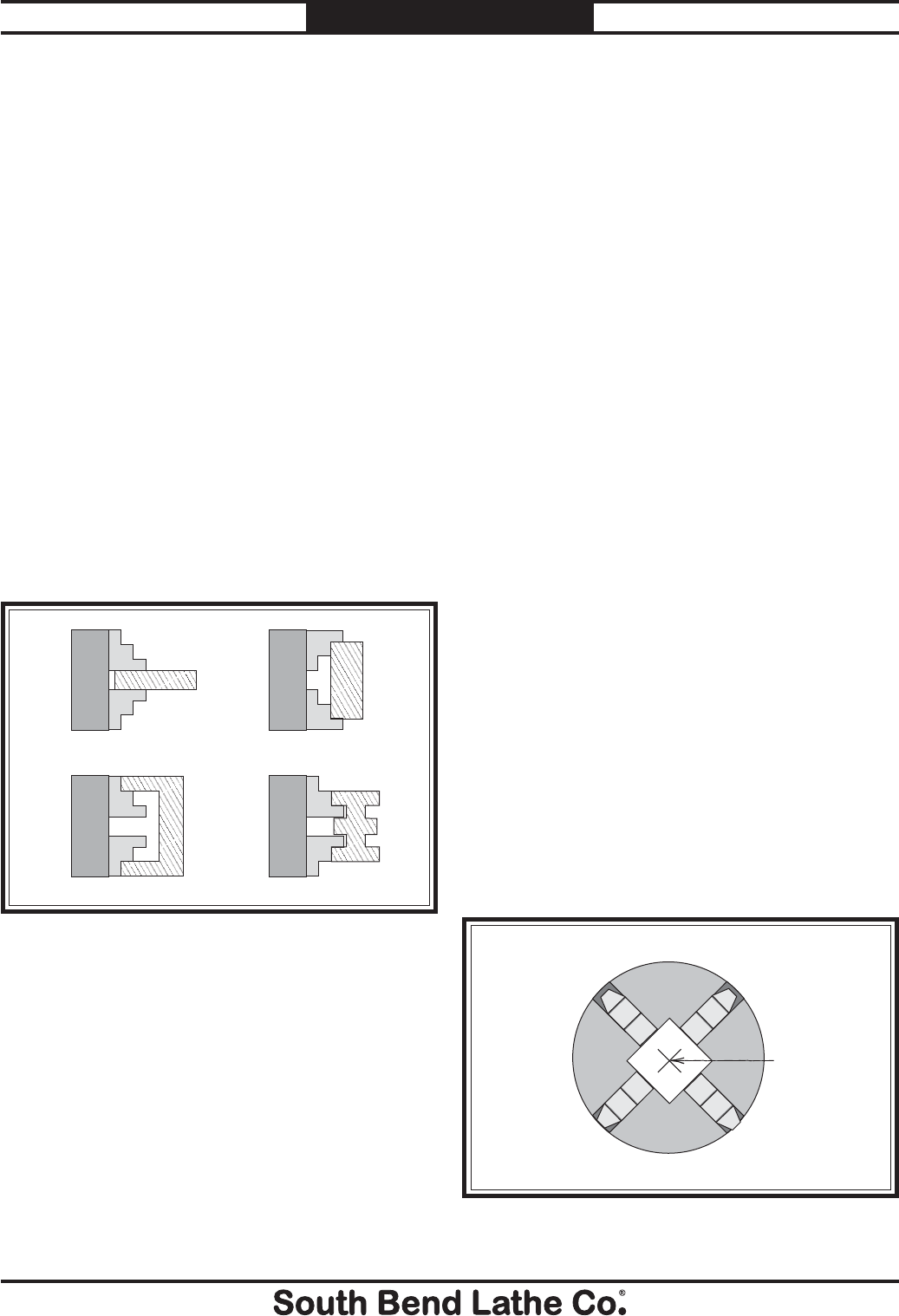
-40-
For Machines Mfg. Since 7/09
Model SB1016/SB1036 OPERATION
— If installed correctly, the jaws converge
together at the center of the chuck.
— If the jaws do not come together, the
initial thread was missed on one of the
jaws. Remove all the jaws and start again.
Mounting Workpiece
Items Needed .....................................................Qty
Chuck Key ............................................................. 1
Chuck Cradle or Plywood 3⁄4" (to protect bed) .... 1
To mount a workpiece in the 3-jaw chuck:
1. DISCONNECT LATHE FROM POWER!
2. If the workpiece is large and heavy, place a
chuck cradle or plywood on the bedway below
the chuck to protect it.
3. Use the chuck key to move the jaws and
mount the workpiece into the chuck (refer to
Figure 59 for typical mounting methods).
4. Rotate the chuck by hand to make sure the
workpiece makes even contact with all three
jaws and spins evenly without any visible
wobble.
— If the workpiece is not evenly held or is
off-center, repeat Steps 3–4.
5. After verifying that the workpiece is properly
centered, fully tighten the jaws to make sure
the workpiece is held securely, so it will not
come loose during operation.
Figure 59. Typical of 3-jaw chuck mounting methods.
Mounting on an Outside Diameter
Mounting in an Inside Diameter
4-Jaw Chuck
Refer to Chuck & Faceplate Mounting
instructions on Page 35 to mount the 4-jaw
chuck to the spindle.
The 4-jaw chuck features independently
adjustable hardened steel jaws to hold non-
cylindrical or off-center workpieces. Each jaw can
be removed from the chuck body and reversed for
a wide range of work holding versatility.
Mounting Workpiece
Items Needed Qty
Chuck Key ............................................................. 1
Chuck Cradle or Plywood 3⁄4" (to protect bed) ...... 1
To mount a workpiece on the 4-jaw chuck:
1. DISCONNECT LATHE FROM POWER!
2. Place a chuck cradle or plywood on the
bedway below the chuck to protect it.
3. Use the chuck key to open each jaw so the
workpiece will lay flat against the chuck face
or jaw steps.
4. With help from another person or a
supporting device, mount the workpiece
centered on the chuck, then turn each jaw
until it makes contact with the workpiece.
5. Tighten each jaw in small increments. After
you have adjusted the first jaw, continue
tightening in an opposing sequence, as
shown in Figure 60.
Figure 60. 4-jaw tightening sequence.
1
2
3
4
Workpiece
Center Point
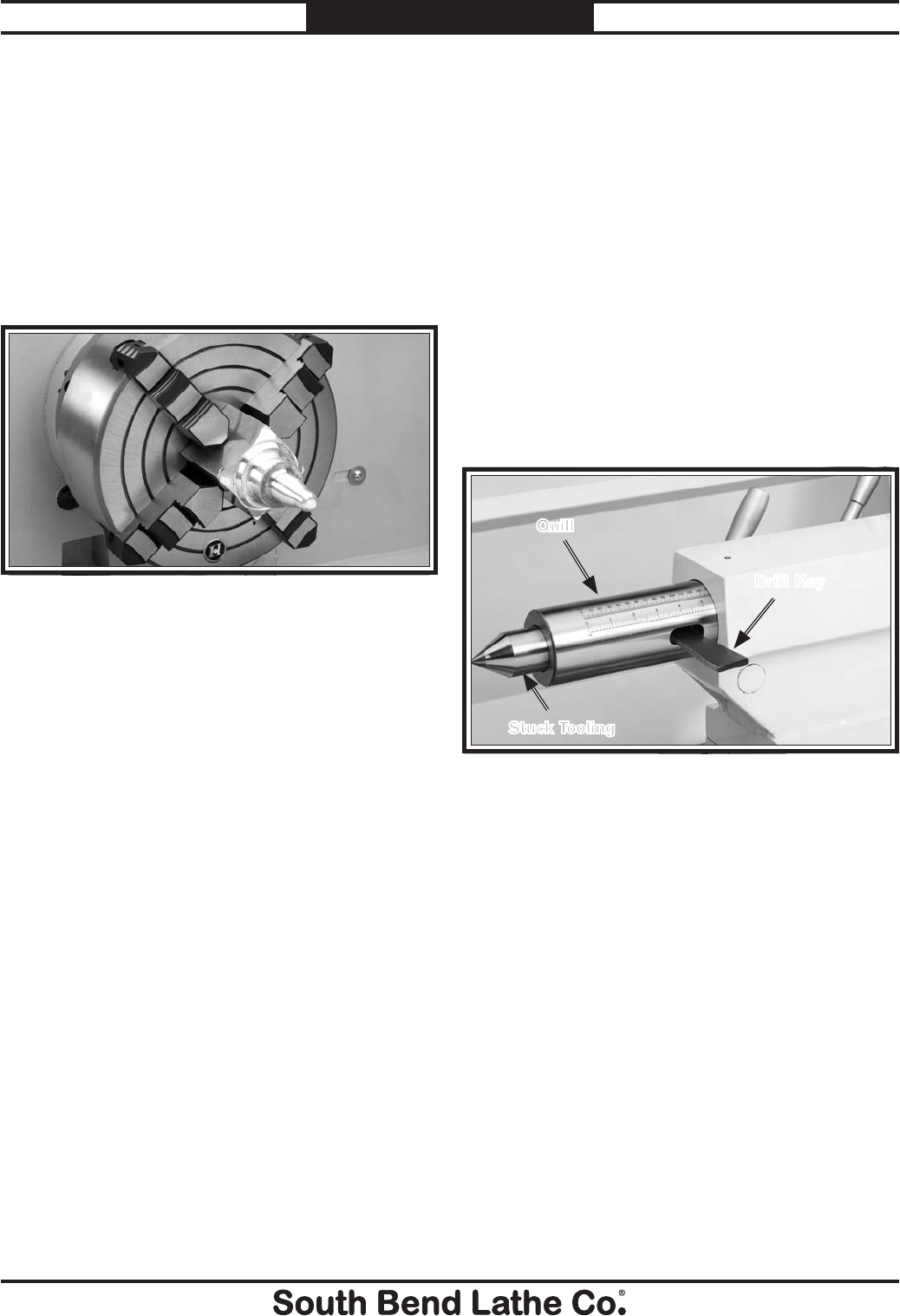
For Machines Mfg. Since 7/09 Model SB1016/SB1036
-41-
OPERATION
6. After the workpiece is held in place by
the jaws, turn the chuck by hand and pay
attention to the workpiece alignment.
— If the workpiece is not correctly aligned
for your operation, turn the chuck and
make fine adjustments by slightly
loosening one jaw and tightening the
opposing jaw until the workpiece is
correctly aligned (see Figure 61 for an
example).
Figure 61. Example of non-concentric workpiece
correctly mounted on the 4-jaw chuck.
Tailstock
The tailstock is typically used to support long
workpieces by means of a live or dead center
(refer to Centers on Page 47). It can also be
used to hold a drill or chuck to bore holes in
the center of a part. Custom arbors and tapers
can also be cut on your lathe by using the off-
set tailstock adjustment screws shown in (see
Figure 63).
The tailstock quill is 3" diameter, has an MT#5
taper, and has 6
1⁄2" of travel. If a tool ever
becomes stuck in the bore where using the
handwheel cannot extract the tool, the quill is
also equipped with a slot for using a drift key
(see Figure 62) to remove the stuck tool.
Figure 62. Tailstock controls.
Drift Key
Quill
Stuck Tooling
Cut into the quill is a 6
1⁄2" long inch-scale that is
broken down into 1⁄8" increments, and a 16.8cm
long metric scale that is and is broken down in
millimeters. Inside of the quill at the end, an
internal slot is present to accept drill and arbor
lock tangs. This feature is especially useful when
the tailstock is expected to hold large diameter
drill bits where the torque loads would break
most tooling free.
When maximum rigidity is mandatory, the
tailstock has a secondary lock bolt and clamp (see
Figure 64) that adds additional clamping force
to that of the standard tailstock lever.
The handwheel is quipped with a graduated
collar that is broken down in increments of
0.001" where 360°= 0.200" of quill travel.
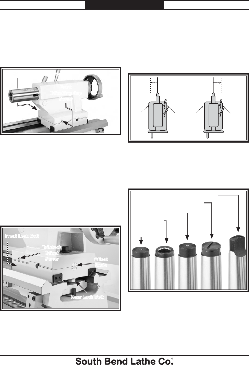
-42-
For Machines Mfg. Since 7/09
Model SB1016/SB1036 OPERATION
The tailstock can be offset from the spindle
centerline for turning tapers. The offset
movement is controlled by two opposing cap
screws on the front and back sides of the
tailstock (see Figure 63).
Figure 63. Offsetting cap screw.
The amount of movement is indicated by the
offset scale on the back of the tailstock (see
Figure 64). However, since the actual value of
the scale is a function of workpiece length. The
angle increments of the offset scale have been
left as arbitrary lines only intended for use as a
quick reference.
For actual calculations when returning the
tailstock to the lathe centerline or defining
actual angles, use a test indicator to check quill
movement while adjusting screws.
Offsetting
Rear Offsetting Cap Screw
Front
Offsetting Cap
Screw
Tool Needed Qty
Hex Wrench 6mm .................................................1
Wrench 28mm ....................................................... 1
To offset the tailstock from the spindle
centerline, loosen the tailstock, and the front and
rear lock bolts, then rotate the tailstock offset
screws shown in Figures 64–65.
Turn
CCW
Turn
CCW
Turn
CW
Turn
CW
Figure 65. Tailstock offset screw adjustment.
Installing Tooling
This tailstock uses a quill with an MT#5 taper
with a lock slot at the bottom to accept lock tang
arbors and drill bits (see Figure 66).
Figure 66. Types of tapered arbors and tooling.
Standard Length w/Lock Tanged End
Short Length
w/Solid End
Standard Length w/Screw End
Short Length
w/Open End
Standard Length w/Solid End
The tang is essential to prevent an arbor or drill
bit from breaking loose should the bit grab the
workpiece suddenly, or if the drill bit is under
heavy torque. If tooling spins inside the quill, it
will gall the tapered mating surfaces. Repairing
this type of damage can be time consuming or
require outright quill replacement.
Figure 64. Tailstock offset scale.
Offset
Scale
Rear Lock Bolt
Front Lock Bolt
Tailstock
Offset
Screw
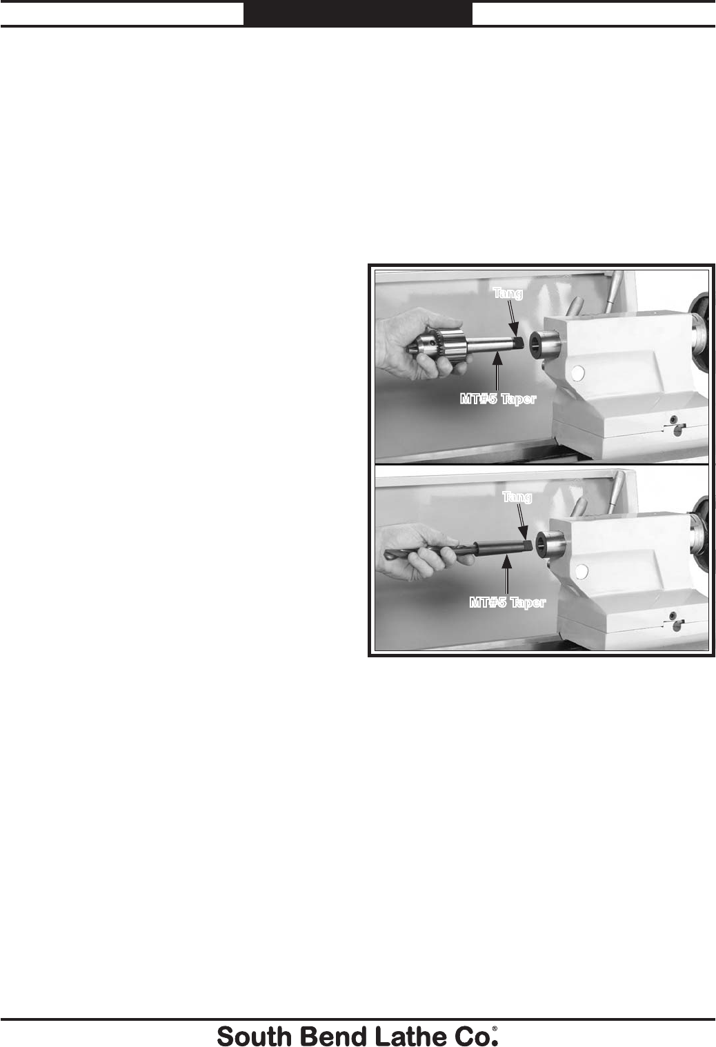
For Machines Mfg. Since 7/09 Model SB1016/SB1036
-43-
OPERATION
However, other tooling without lock tangs, such
as the remaining four shown in Figure 66, can
still be used if the following two conditions exist:
1. If the potential torque load from smaller
drill chucks, drill bits, and centers will not
override the strength of the MT#5 tapered
fit, the tool can be used.
2. Usually the end of the arbor or tool that fits
into the quill must be solid and a standard
length.
If the center or tooling has an open hole in the
end of the arbor but is too short to be exposed in
the drift slot for removal, then a screw should be
threaded into the end of the tool. Covering this
hole will provide a solid surface for tailstock pin
to push against when the handwheel is backed
off for tool removal. Also, these short tools do not
seat far enough into the quill to be exposed in the
drift slot. As a result, the edge of the drift key
cannot contact the tool to push it out of the quill.
Should a tool become stuck under these
conditions, remove the quill or handwheel and
drive the arbor or tool out with a long punch.
Figure 67. Inserting drill chuck arbor or tapered drill
bit into tailstock.
Tang
MT#5 Taper
Tang
MT#5 Taper
To remove a tapered drill bit or chuck arbor:
Hold the arbor or drill bit with a rag, and turn
the handwheel counterclockwise until the tooling
is pushed out from the tailstock taper.
— If the arbor or drill bit is stuck in the
bore and cannot be removed by using the
handwheel with moderate force, do not apply
extra leverage to the handwheel. Instead,
extend the quill to expose the drift key slot
in the quill, and use a drift key (see Figure
62) to remove the stuck tool.
To install a tapered drill or chuck:
1. Lock the tailstock in position, then unlock
the quill.
2. Use the tailstock handwheel to extend the
quill about one inch out of the tailstock.
3. Insert a tapered drill arbor (Figure 67), or
the tapered drill shank, into the quill until
the taper is firmly seated. The matching
tapers hold the arbor.
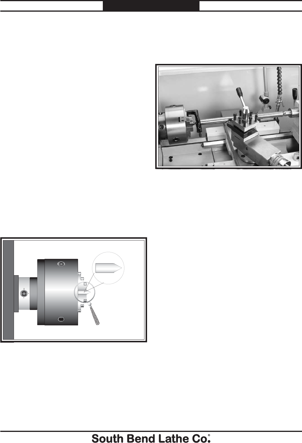
-44-
For Machines Mfg. Since 7/09
Model SB1016/SB1036 OPERATION
Aligning
The offset of your lathe was aligned with
the spindle centerline at the factory. We
recommend that you take the time to ensure
that the tailstock is aligned to your own desired
tolerances, especially if you have changed the
offset to cut shallow tapers.
To align the tailstock offset to the spindle
centerline:
1. Use a precision level to make sure the
bedway is level from side-to-side and from
front-to-back.
— If the bedway is not level, correct this
condition before continuing with this
procedure.
2. Obtain two pieces of steel round stock 2" in
diameter and 6" long.
3. Center drill both ends of one piece of round
stock, then set it aside for use in Step 6.
4. Use the other piece of round stock to make
a dead center, and turn it to a 60° point, as
shown in Figure 68.
Figure 68. Non tapered dead center in the chuck.
5. Install a center in the tailstock.
6. Attach a lathe dog to the piece of stock from
Step 3, then mount it between the centers,
as shown in Figure 69.
Figure 69. Example of round stock mounted between
the centers.
7. Turn 0.010" off the diameter of the stock.
8. Mount a test or dial indicator so that the
plunger is on the tailstock quill.
Note: If necessary in the following step, refer to
"To Set Up the Tailstock to Cut a Shallow
Taper" on Page 42 for adjusting the
tailstock offset.
Note: As long as this dead center remains in the
chuck, the point of the center will remain
true to the spindle centerline. The point will
have to be refinished whenever the center is
removed and then returned to the chuck.
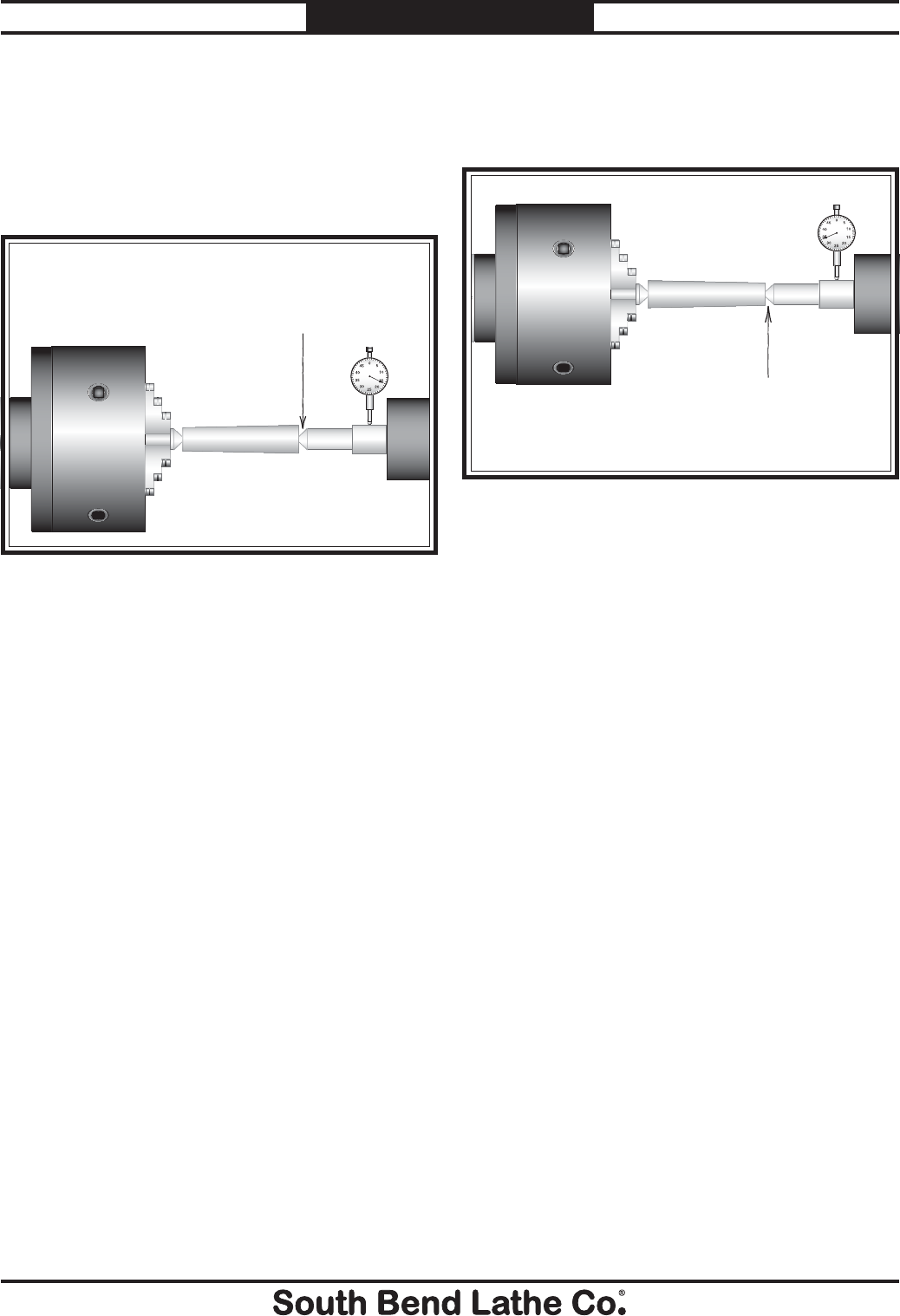
For Machines Mfg. Since 7/09 Model SB1016/SB1036
-45-
OPERATION
9. Use calipers to measure both ends of the
workpiece.
— If the machined workpiece is thicker
at the tailstock end, move the tailstock
toward the operator 1⁄2 the distance of the
amount of taper (see Figure 70).
10. Repeat Steps 7–9 until the desired accuracy
is achieved.
Move the tailstock toward
the operator half the
distance of the taper.
Looking down from above.
Figure 70. Adjust tailstock toward the operator.
— If the machined workpiece is thinner at
the tailstock end, move the tailstock away
from the operator 1⁄2 the distance of the
amount of taper (see Figure 71).
Move tailstock away from
the operator half the
distance of the taper.
Looking down from above.
Figure 71. Adjust tailstock away from the operator.
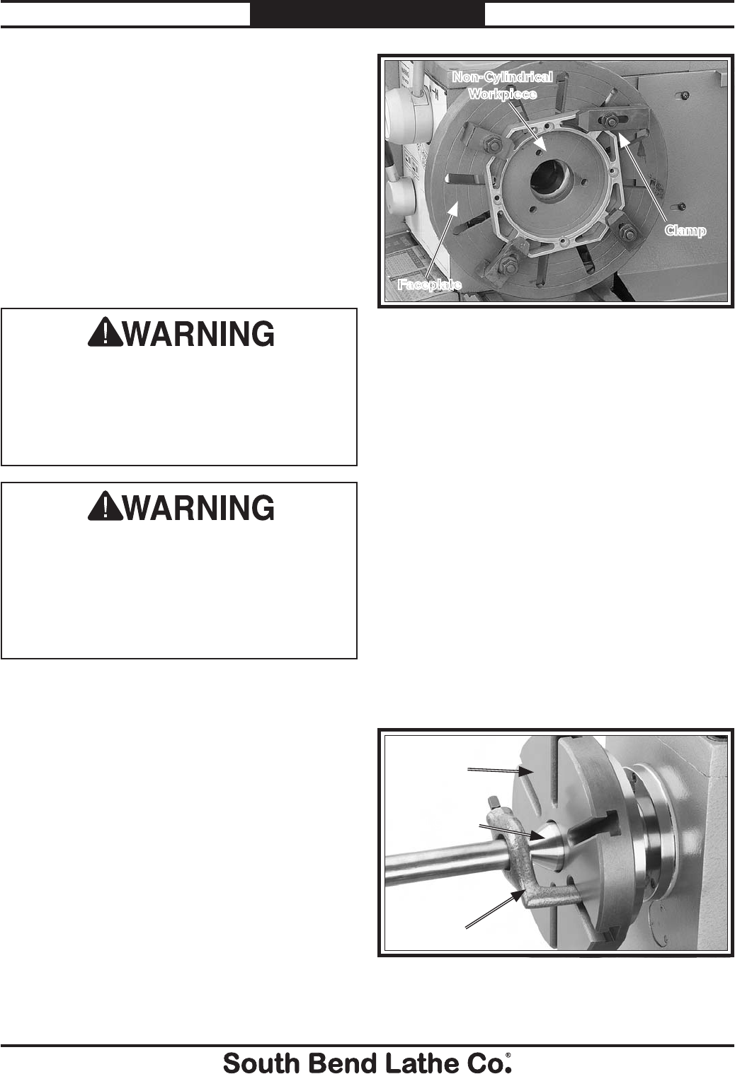
-46-
For Machines Mfg. Since 7/09
Model SB1016/SB1036 OPERATION
Faceplate
Refer to Chuck & Faceplate Mounting
instructions on Page 35 to mount the faceplate
to the spindle.
The 15" faceplate included with your lathe offers
a wide range of uses, including machining non-
concentric workpieces, straight turning between
centers, off-center turning, and boring.
The tools needed for mounting a workpiece will
vary depending on the type of setup you have.
Mounting Workpiece with Clamps
1. DISCONNECT LATHE FROM POWER!
2. Place a piece of 3⁄4" plywood on the bedway
below the spindle.
3. With help from another person, place the
workpiece onto the faceplate and clamp it in
place with a minimum of three independent
clamping devices (see Figure 72 for an
example).
Note: Be sure to take into account the rotation
and cutting forces that will be applied to the
workpiece when clamping it to the faceplate.
4. Double check tool and slide motion
clearances before turning the spindle ON.
Mounting Workpiece Between
Centers
1. DISCONNECT LATHE FROM POWER!
2. Drill center holes in both ends of the
workpiece.
3. Install the dead center in the spindle and the
live center or carbide-tipped dead center in
the tailstock (refer to Page 47).
4. Secure a lathe dog on the spindle-end and
place a drop of oil in the center hole on the
tailstock-end of the workpiece.
5. Mount the workpiece between centers so the
lathe dog tail fits freely in the faceplate slot
without binding as shown in Figure 73.
Failure to properly secure a workpiece to the
faceplate could cause the workpiece to be
thrown from the lathe with deadly force at the
operator or bystanders. Use a minimum of
three independent clamping devices to hold a
non-concentric workpiece onto the faceplate.
Machining non-concentric workpieces at a
high speed could cause the workpiece to be
thrown from the spindle with deadly force at
the operator or bystanders. To reduce this
risk, only machine non-concentric workpieces
at low speeds and clamp counter-weights to
the faceplate to balance it.
Figure 72. Example of workpiece clamped in a
faceplate.
Clamp
Non-Cylindrical
Workpiece
Faceplate
Figure 73. Example of using a typical faceplate to
mount work between centers.
Dead Center
Lathe Dog
Faceplate
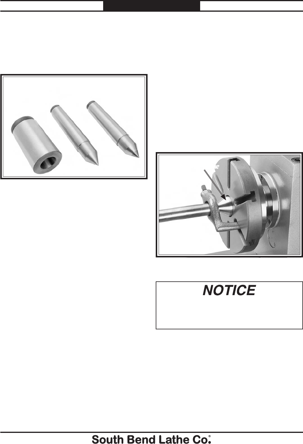
For Machines Mfg. Since 7/09 Model SB1016/SB1036
-47-
OPERATION
Mounting Center in Spindle
1. DISCONNECT LATHE FROM POWER!
2. Thoroughly clean and dry the tapered
mating surfaces of the spindle bore, tapered
sleeve, and the center, making sure that no
lint or oil remains on the tapers.
3. Insert the center into the sleeve, then insert
the sleeve into the spindle bore through the
chuck or faceplate.
Figure 75 shows an example of the dead
center installed in the spindle, using a
lathe dog and faceplate for turning between
centers.
Centers
Figure 74 shows the dead centers included with
the lathe. In addition, an MT#7–MT#5 tapered
spindle sleeve is included for mounting centers in
the spindle.
Dead Centers
The dead center achieves more accurate
results than a live center, but it requires low
spindle speeds and a small amount of oil to
reduce friction and wear that will damage the
workpiece.
Use the dead center in the spindle, since the
workpiece does not rotate on the tip and does not
generate friction.
Use the carbide-tipped dead center in the
tailstock where the workpiece will rotate against
it and generate friction. The carbide-tipped dead
center can better withstand the effects of friction;
however, the tip of the center must be lubricated
to avoid premature wear and maximize smooth
operation. Also, using low spindle speeds will
also reduce the heat and wear from friction.
Live Centers
A live center has bearings that allow the center
tip and the workpiece to rotate together; it can be
installed in the spindle and the tailstock quill for
higher speeds. However, a live center typically
does not provide the same level of rigidity as a
dead center, and final workpiece accuracy can
suffer as a result.
Figure 74. Tapered sleeve and dead centers.
Tapered
Sleeve
Dead Center
Carbide Tipped
Dead Center
Figure 75. Example of using a dead center with a
faceplate and lathe dog.
Dead Center
To avoid premature wear of the dead center
or damage to the workpiece, use low spindle
speeds and keep the tip of the dead center
mounted in the tailstock well lubricated.
Removing Center from Spindle
To remove the sleeve and center from the
spindle, insert a piece of round bar stock or
similar tool through the outboard end (on the left
side of the headstock), then while holding the
sleeve, have a second person tap the sleeve loose.
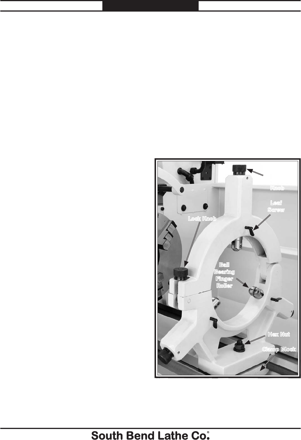
-48-
For Machines Mfg. Since 7/09
Model SB1016/SB1036 OPERATION
Mounting Center in Tailstock
Either the carbide-tipped dead center or a live
center can be mounted in the tailstock. Mounting
instructions are the same for both.
To mount a center in the tailstock:
1. DISCONNECT LATHE FROM POWER!
2. Thoroughly clean and dry the tapered
mating surfaces of the tailstock quill bore
and the carbide-tipped dead center, making
sure that no lint or oil remains on the tapers.
3. Use the tailstock quill handwheel to feed the
quill out from the casting about 1". (Do not
feed the quill out of the casting more than 2"
or stability and accuracy will be reduced.)
4. Insert the center into the tailstock quill.
5. Seat the center firmly into the quill during
workpiece installation by rotating the quill
handwheel clockwise to apply pressure, with
the center engaged in the center hole in the
workpiece.
Note: Only apply enough pressure with the
tailstock quill to securely mount the
workpiece between centers. Avoid over-
tightening the center against the workpiece,
or it may become difficult to remove later,
and it will result in excessive friction and
heat, which may damage the workpiece and
the center.
Removing Center from Tailstock
To remove the center from the quill, hold onto it
with a rag in one hand, then rotate the tailstock
handwheel counterclockwise to draw the quill
back into the casting until the center releases.
If the center does not come out, extend the quill,
and use a drift key (see Figure 62) to drive the
center out.
The steady rest supports long shafts from 3⁄4" to
8
3⁄4" in diameter and can be mounted anywhere
along the length of the bed.
To install and use the steady rest:
1. DISCONNECT LATHE FROM POWER!
2. Thoroughly clean all mating surfaces, then
place the steady rest base on the bedways
so the triangular notch fits over the bedway
prism.
3. Position the steady rest where required to
properly support the workpiece, then tighten
the hex nut shown in Figure 76.
Steady Rest
4. Loosen the lock knob (Figure 76), open the
steady rest, and install the workpiece so it is
supported at both ends.
Figure 76. Steady rest components.
Lock Knob
Hex Nut
Finger
Adjustment
Knob
Ball
Bearing
Finger
Roller
Leaf
Screw
Clamp Block
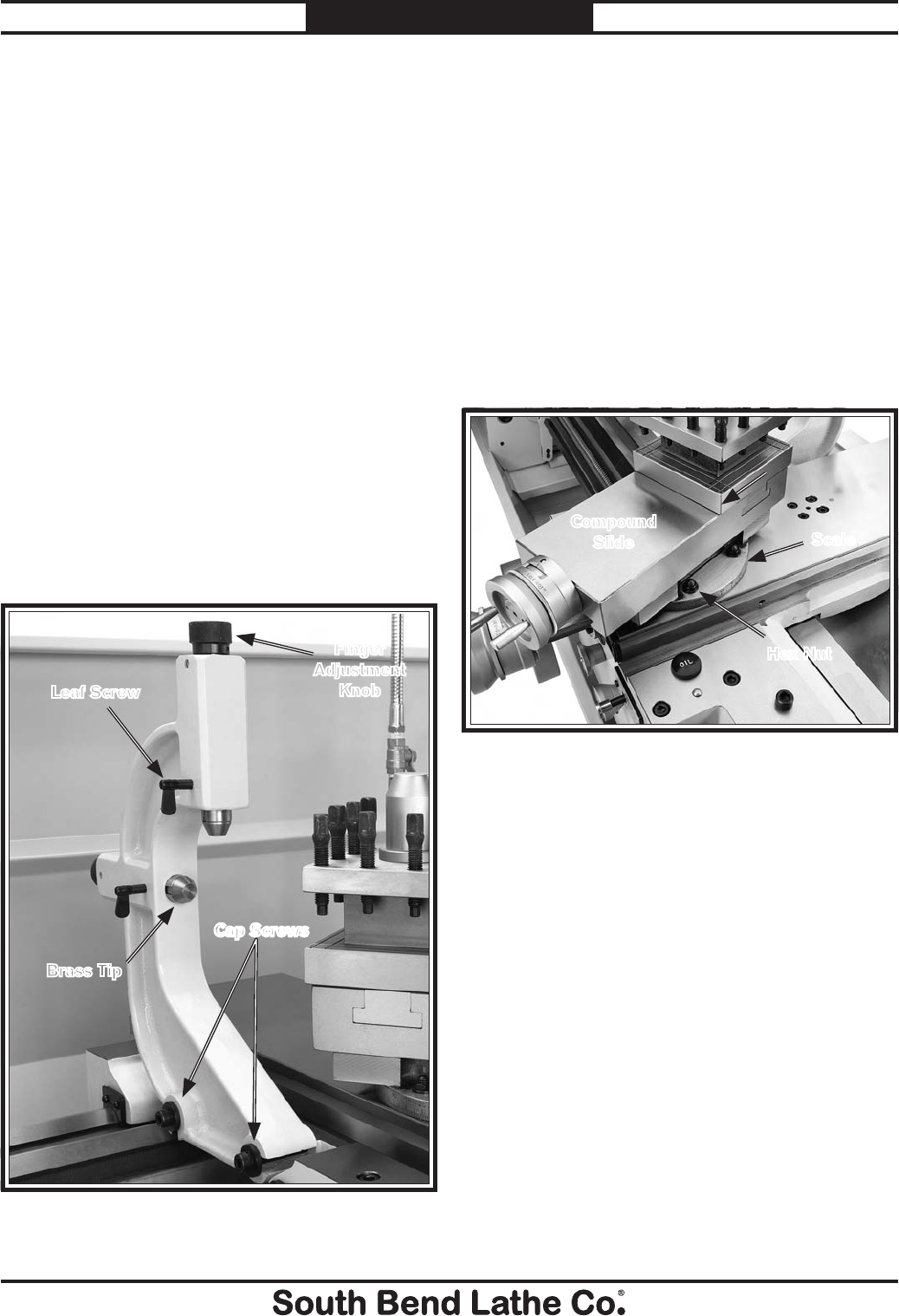
For Machines Mfg. Since 7/09 Model SB1016/SB1036
-49-
OPERATION
5. Close the steady rest and tighten the lock
knob.
6. Loosen the three leaf screws. Without
causing any deflection in the workpiece, use
the finger adjustment knobs to position the
finger rollers against the workpiece.
7. Tighten the leaf screws.
Note: The finger rollers should properly support
the workpiece but allow it to freely rotate.
Follow Rest
The follow rest mounts to the saddle with two
cap screws (Figure 77). It is used on long,
slender parts to prevent workpiece flexing from
the pressure of the cutting tool during operation.
Adjust the fingers on the follow rest in the same
manner as those on the steady rest. To avoid
marring, make sure to keep the contact surface
well oiled during turning operations.
2. Rotate the compound slide to the desired
angle, as indicated by the scale at the base,
then retighten the two hex nuts.
Tip: If setting up to cut external right-hand inch
or metric threads, or left-hand internal
threads for the first time, set the compound
so its travel is perfectly parallel with the
cross slide. Using a protractor, rotate the
compound 29.5° counterclockwise and mark
the new location on the compound slide. This
mark will be the quick reference point for
setting the offset angle. To mark for internal
right-hand threads, or left-hand external
threads, repeat this process, but rotate the
compound 29.5° clockwise and mark the
cross slide accordingly.
Figure 78. Compound slide set at an angle.
Hex Nut
Compound
Slide
The compound slide handwheel has an indirect-
read graduated collar. This means that the
distance shown on the scale represents the
actual distance the tool moves, which will remove
twice as much material from the diameter of the
workpiece. The base of the compound slide has
another graduated collar used for setting the tool
to a specific angle.
To set the compound slide at a certain angle:
1. Loosen the two hex nuts at the base of the
compound slide (1 of 2 shown in Figure 78).
Compound Slide
Scale
Figure 77% Follow rest attachment.
Cap Screws
Cap Screws
Leaf Screw
Finger
Adjustment
Knob
Brass Tip
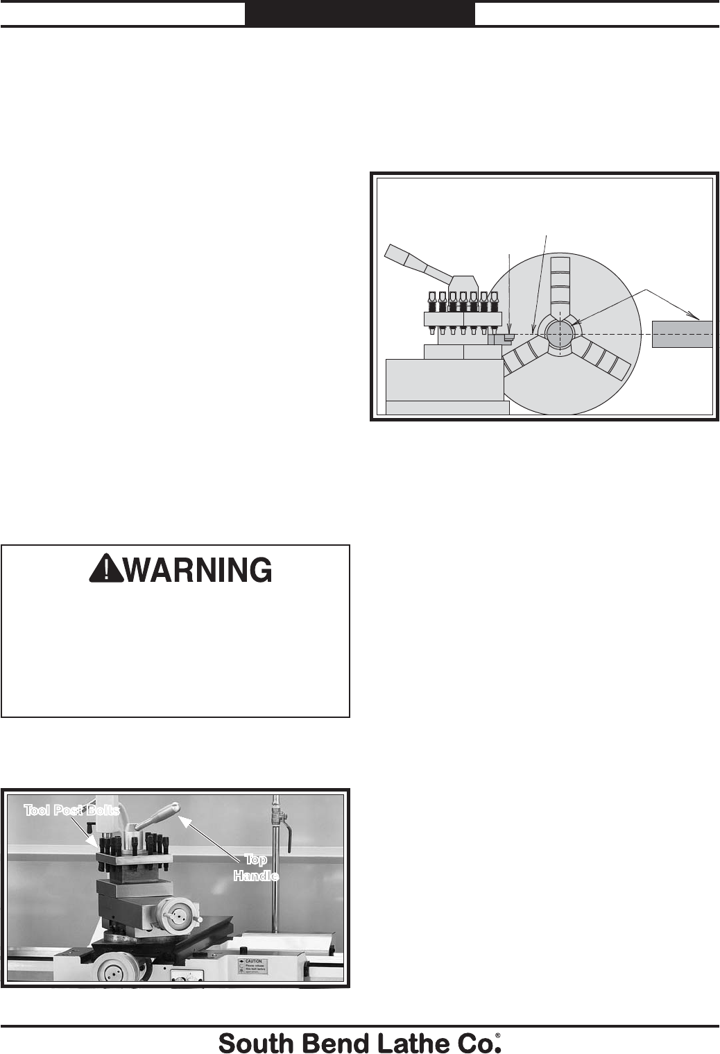
-50-
For Machines Mfg. Since 7/09
Model SB1016/SB1036 OPERATION
The 4-way tool post is mounted on top of the
compound slide, and allows a maximum of four
tools to be loaded simultaneously. Quick indexing
to different tools is accomplished by loosening the
top handle, rotating the tool post to the desired
position, then re-tightening the handle to lock
the tool into position.
Tool Needed Qty
Tool Post T-Wrench ............................................... 1
To load the tool post:
1. Choose the desired cutting tool.
2. Loosen the tool post bolts so that the cutting
tool can fit underneath them.
Note: If necessary, place one steel shim of the
required thickness underneath the cutting
tool, so the cutting tip is properly aligned
with the workpiece. The shim should be
as long and as wide as the cutting tool
to properly support it, a set of standard
automotive feeler gauges work well for this.
4-Way Tool Post
3. Firmly secure the cutting tool with at least
two tool post bolts shown in Figure 79.
Figure 79. 4-Way tool post.
To p
Handle
Tool Post Bolts
Over-extending a cutting tool from the tool
post will increase the risk of it breaking during
operation, which may cause metal pieces to
be thrown at the operator or bystanders with
great force. Only extend a cutting tool 2.5
times the width of its cross-section or less
(i.e., 2.5 x 0.5" = 1.25").
Aligning Cutting Tool with Spindle
Centerline
For most operations, the cutting tool tip should
be aligned with the spindle centerline, as
illustrated in Figure 80.
Figure 80. Cutting tool aligned with workpiece center
(view from tailstock).
Cutting
Tool
Workpiece
Workpiece
Center
Line
There are a number of ways to check and align
the cutting tool to the spindle centerline. Below
are two common methods:
Align the tip of the cutting tool with a center s
installed in the tailstock (refer to instructions
that follow). For this to work, the tailstock
must be aligned to the spindle centerline
(refer to Aligning Tailstock on Page 44).
Make a facing cut on a piece of round bar s
stock. If the tool is above/below the spindle
centerline, a nub will be left in the center
of the workpiece. Adjust the height of the
workpiece, then repeat the facing cut to check
the adjustment. Repeat as necessary until the
center of the workpiece is smoothly faced.
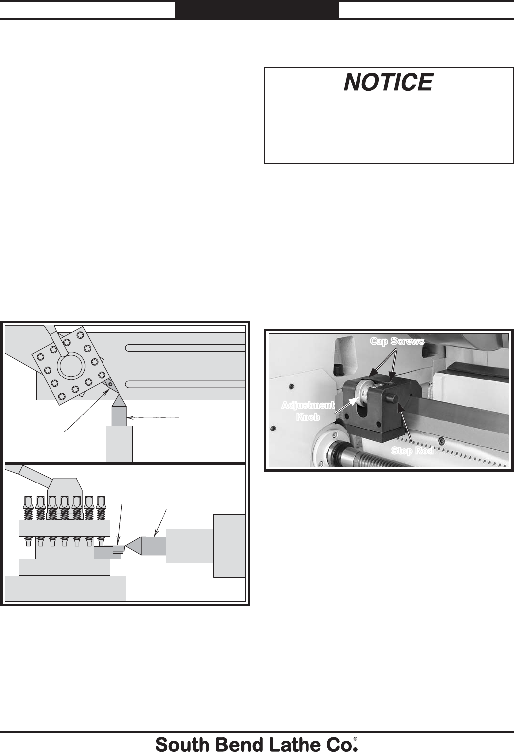
For Machines Mfg. Since 7/09 Model SB1016/SB1036
-51-
OPERATION
Tools Needed Qty
Tool Post T-Wrench ............................................... 1
Steel Shim ............................................. As Needed
Cutting Tool ........................................................... 1
Fine Ruler ..............................................................1
Tailstock Center ....................................................1
To align the cutting tool with the tailstock
center:
1. Mount the cutting tool in the tool post, then
turn the tool post so the tooling faces the
tailstock.
2. Install a center in the tailstock, and position
the center tip near the tip of the cutting tool.
3. Lock the tailstock and quill in place.
4. Adjust the height of the cutting tool with a
steel shim, so the tip just touches the end of
the tailstock center, as shown in Figure 81.
Figure 81. Cutting tool tip aligned with tailstock
center.
Cutting
Tool
Tailstock
Center
(Top View)
Cutting
Tool Tailstock
Center
(Side View)
Micrometer Stop
The micrometer stop on this lathe will NOT
automatically stop the carriage or disengage
the power feed! Failure to heed this notice
could result in the carriage crashing and
causing severe machine or property damage.
Use the micrometer stop as a guide to help judge
when to stop the carriage movement. The scale
increments are 0.001" where 360°=0.050".
Tools Needed Qty
Hex Wrench 8mm .................................................1
To adjust the micrometer stop:
1. DISCONNECT LATHE FROM POWER!
2. Loosen the cap screws shown in Figure 82.
3. Use the carriage handwheel to position the
carriage/cutting tool at the stop point you
want to set (typically the maximum distance
the carriage can travel before there is a
crash).
4. Position the micrometer stop so the stop rod
is firmly against the carriage, retighten the
cap screws loosened in Step 2, and use the
adjustment knob to fine tune the position of
the stop rod.
5. Move the carriage away from the stop rod,
then move it back against the stop rod and
verify that tooling will not make contact with
chuck, jaws, or other components (rotate the
chuck by hand to verify rotational clearance).
Figure 82. Micrometer stop.
Stop Rod
Adjustment
Knob
Cap Screws
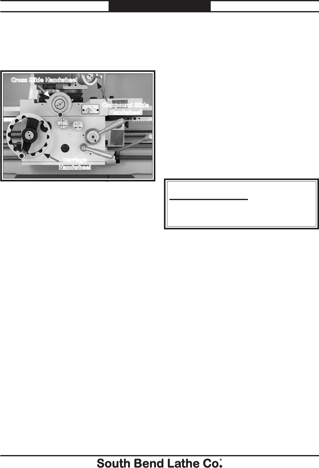
-52-
For Machines Mfg. Since 7/09
Model SB1016/SB1036 OPERATION
Manual Feed
These three handwheels (see Figure 83)
manually position and control the cutting tool for
lathe operations.
Carriage Handwheel
Moves the carriage parallel along the ways,
and is equipped with a graduated collar in
increments of 0.010" where 360°= 0.990". The
handwheel can also be disengaged when power
feed operations would make it an entanglement
hazard by pushing it in.
Cross Slide Handwheel
Moves the cross slide perpendicular to the ways.
For every revolution of the handwheel, the slide
moves twice the distance or at a at a 1:2 ratio.
The graduated collar indicates in increments
of 0.001"where 360°= 0.200". When turning for
example the scale directly reads the resulting
workpiece diameter.
Compound Slide Handwheel
Moves the tool in fine increments into the
workpiece. The handwheel has an "indirect
reading" graduated collar that is broke down
in 0.001" increments. When the tool path is
perpendicular to the workpiece, the movement
that is shown on the scale is only half of what
has been removed from the workpiece. For
example, if the handwheel is rotated 0.001"
the compound slide and tool bit moves 0.001".
This results in 0.002: being removed from the
workpiece diameter.
Figure 83. Carriage handwheels.
Cross Slide Handwheel
Compound Slide
Handwheel
Carriage
Handwheel
Spindle Speed
Using the correct spindle speed is important
for safe and satisfactory results, as well as
maximizing tool life.
To set the spindle speed for your operation, you
will need to: (1) Determine the best spindle speed
for the cutting task, and (2) configure the lathe
controls to produce the required spindle speed.
Determining Spindle Speed
Many variables affect the optimum spindle speed
to use for any given operations, but the two most
important are the recommended cutting speed
for the workpiece material and the diameter of
the workpiece, as noted in the formula shown in
Figure 84:
Cutting speed, typically defined in feet per
minute (FPM), is the speed at which the edge of a
tool moves across the material surface.
A recommended cutting speed is an ideal speed
for cutting a type of material in order to produce
the desired finish and optimize tool life.
The books Machinery’s Handbook or Machine
Shop Practice, and some internet sites, provide
excellent recommendations for which cutting
speeds to use when calculating the spindle speed.
These sources also provide a wealth of additional
information about the variables that affect
cutting speed and they are a good educational
resource.
Also, there are a large number of easy-to-use
spindle speed calculators that can be found on
the internet. All of these sources will help you
take into account all the applicable variables in
order to determine the best spindle speed for the
operation.
Cutting Speed (FPM) x 12
*Recommended
Dia. of Cut (in inches) x 3.14
= SpindleSpeed (RPM)
*Double if using carbide cutting tool
Figure 84. Spindle speed formula for lathes.
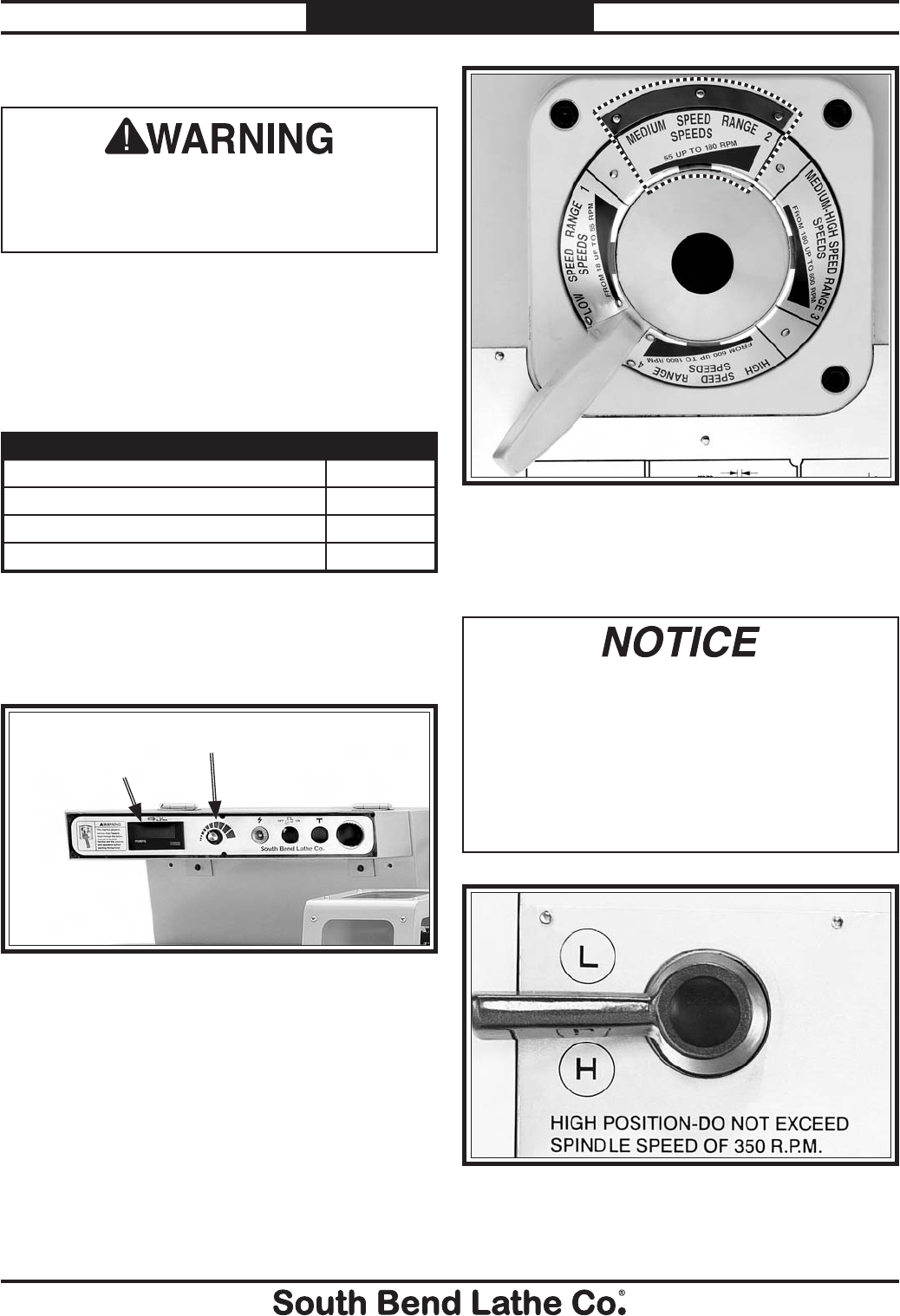
For Machines Mfg. Since 7/09 Model SB1016/SB1036
-53-
OPERATION
Figure 87. Spindle speed range lever.
Setting Spindle Speed
5. Turn the spindle ON, and slowly turn the
spindle speed dial to your calculated spindle
speed.
Figure 88. Quick change range lever.
If using the quick change gearbox, and it is
shifted into high, NEVER run the spindle at
speeds greater than 350 RPM as listed on
the label (Figure 88), or feed system damage
will occur. DO NOT shift any levers on the
headstock or quick change gearbox while the
spindle is turning, or damage will occur to the
gearing.
Make sure the variable speed dial is turned all
the way to the left (counterclockwise) before
turning the lathe ON, or the spindle may start
up at a dangerously high rate of speed.
4. Move the spindle range lever shown in
Figure 87 to the range that covers your
calculated spindle speed.
Note: To shift the spindle speed range lever, you
may need to rock the chuck by hand to get
the gears to align.
Figure 86. EVS spindle speed controls.
Spindle Speed DialSpindle Speed
RPM Display
3. Turn the spindle speed dial shown in Figure
86 all the way counterclockwise to the
minimum.
1. Make sure the spindle is turned OFF and it
has come to a complete stop.
2. Use the chart in Figure 85 to determine the
available spindle speed range closest to your
calculated spindle speed.
SPINDLE SPEED RANGES RPM
Low Speed Range 1 18–55
Medium Speed Range 2 55–180
Medium-High Speed Range 3 180–600
High Speed Range 4 600–1800
Figure 85. Spindle speed range chart.
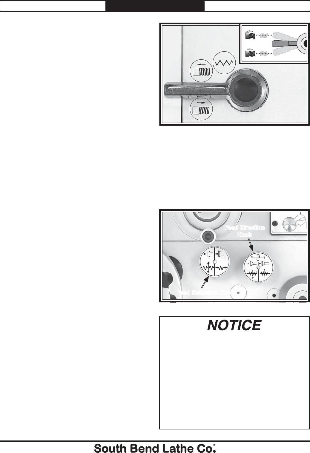
-54-
For Machines Mfg. Since 7/09
Model SB1016/SB1036 OPERATION
Power Feed Controls
The headstock feed direction lever shown in
Figure 89 controls the direction the carriage
moves. However, it is important to understand
that there is a direction change relationship
between the headstock feed direction lever and
the apron feed direction knob (see Figure 90).
The apron feed direction knob and the headstock
feed direction lever reverse the feed direction of
each other. For example:
When the apron feed direction knob is s
pushed-in, the direction of carriage travel
shown on the headstock feed direction lever
plate is applicable only when threading. For
feeding, the directions shown will be opposite.
When the apron feed direction knob is pulled-s
out, the direction of carriage travel shown on
the headstock feed direction plate is accurate
only when feeding. For threading, the
directions shown will be opposite.
On this lathe, both the carriage and cross slide
have power feed capability. The power feed
system is protected by an adjustable feed rod
clutch located on the input side of the apron.
The rate that these components move (feed rate)
is controlled by how the quick change gearbox
levers are configured.
Feed rate and spindle speed must be considered
together. The sources you use to determine the
optimum spindle speed for an operation will also
provide the optimal feed rate to use with that
spindle speed. Often, the experienced machinist
will use the feeds and speeds given in their
reference charts or web calculators as a starting
point, then make minor adjustments to the feed
rate (and sometimes spindle speed) to achieve
the best results.
The carriage can also be driven by the leadscrew
for threading operations. However, this section
covers using the power feed option only for non-
threading operations. To learn how to power the
carriage for threading operations, refer to the
Threading Controls section Page 56.
Power Feed
Figure 89. Headstock feed direction lever.
FORWARD
REVERSE
NEUTRAL
The main benefit of the apron feed direction
knob shown in Figure 90 is that it changes the
direction of the selected feed without having
to stop the lathe, and walk over and shift the
headstock feed direction lever.
The feed selection knob shown in Figure 90
engages either the carriage or cross slide feed.
The apron feed direction knob and the
headstock feed direction lever reverse the
feed direction of each other. Before and after
power feed operations, push-in the apron
feed direction knob to the "normal position".
Otherwise, if it is left pulled out, another lathe
operator may move refer to the headstock
plate and select a feed direction selection
lever to his desired, only to suddenly realize
when feeding begins, the feed movement is
opposite what was shown causing possible
carriage crash!
Figure 90. Apron feed knobs.
Feed Selection Knob
Feed Direction
Knob
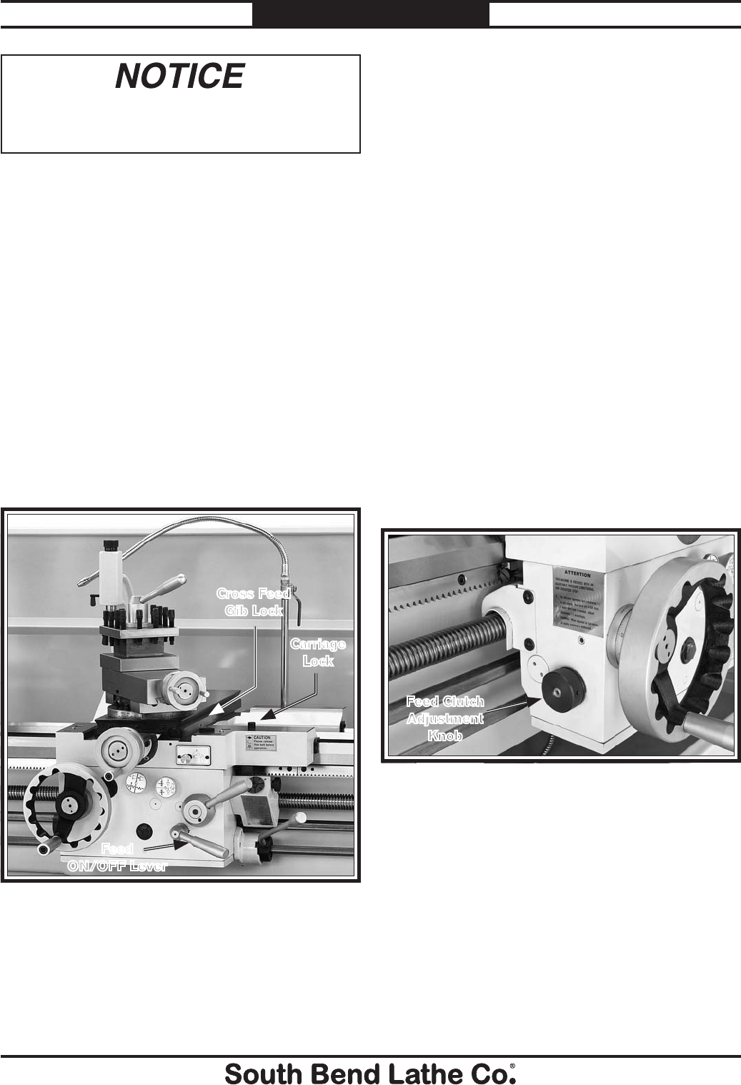
For Machines Mfg. Since 7/09 Model SB1016/SB1036
-55-
OPERATION
If the threading or general carriage feed is
required, the carriage lock (see Figure 91) must
be disengaged. If the cross feed will be used for
facing, the carriage lock should be engaged and
the cross feed gib lock screw (see Figure 91)
should be loose. If it is tight, loosen the cross feed
gib lock using a 3mm hex wrench.
To engage the power feed:
1. Make sure the spindle is OFF and has come
to a complete stop.
2. Shift the headstock feed direction lever to
engage the leadscrew or feed rod. Sometimes
you need to slightly rotate the handwheel of
the component you are trying to engage, so
that the gears can mesh.
NEVER shift the headstock feed direction lever
on the headstock while the spindle is turning,
or damage will occur to the headstock gearing.
3. Push down on the feed ON/OFF lever (see
Figure 91) on the front of the apron to
engage power feed for either the carriage or
the cross slide.
4. Push the feed selection knob in to select
carriage feed, or pull the feed selection knob
out to select cross feed.
5. Adjust the feed clutch knob, shown in
Figure 92, to set at which point the feed
clutch will slip to avoid feed system overload.
— Tighten the feed clutch knob completely
to seat the clutch. Next, count how many
turns it takes to back it off completely.
Then tighten the knob 1⁄3 of the distance
that was backed-off. If the clutch slips
too easily at this conservative setting, the
knob can be tightened further. But keep
in mind that when the knob is completely
tight, the feed clutch is overridden
and will not slip in the event of a feed
system overload, resulting in feed system
damage.
To use the apron feed direction knob during
lathe operations:
1. Pull up on the feed ON/OFF lever to
disengage the apron feed system.
2. Push in or pull out the apron feed direction
knob to change the direction of the current
feed selected.
3. Push down on the feed ON/OFF lever to
resume the feed operation in the opposite
direction.
Figure 92. Feed clutch knob.
Feed Clutch
Adjustment
Knob
Figure 91. Carriage lock and gib lock.
Carriage
Lock
Cross Feed
Gib Lock
Feed
ON/OFF Lever
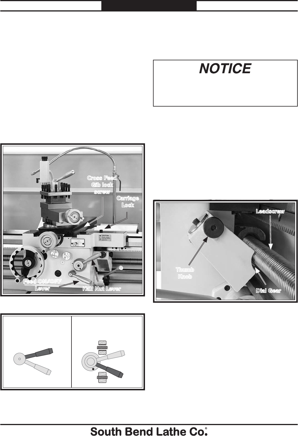
-56-
For Machines Mfg. Since 7/09
Model SB1016/SB1036 OPERATION
Half Nut Lever
The half nut lever locks the carriage to the
leadscrew which moves the cutting tool along the
length of the workpiece (Figures 93–94).
When threading, we recommend using the
slowest speed possible and avoiding deep
cuts, so you are able to disengage the half nut
and prevent an apron crash!
Threading
If you are unfamiliar with how to cut threads on
a lathe, we strongly recommend that you read
books, review industry trade magazines, or get
formal training before beginning any attempting
any threading projects.
Power Feed Lever
The feed ON/OFF lever must be in the fully up
disengaged position or the internal lockout will
prevent the half nut lever from applying the half
nut. Also to avoid shearing the leadscrew shear
pin, the carriage lock (Figures 93–94) must be
loosened before threading begins.
Figure 93. Carriage controls.
Cross Feed
Gib lock
screw
Carriage
Lock
Half Nut Lever
Feed ON/OFF
Lever
Thread Dial & Chart Overview
The numbers on the thread dial are used with
the thread dial chart to show when to engage
the half nut during inch threading or threading
Witworth threads. The thread dial gear must
be engaged with the leadscrew for this to work.
Loosen the knurled thumb knob on the thread
dial, pivot the dial gear into mesh with the
leadscrew, then tighten the hand knob (see
Figure 95).
Figure 95. Thread dial gear engaged with the
leadscrew.
Leadscrew
Dial Gear
Thumb
Knob
Figure 94. Feed ON/OFF lever and half nut positions
for threading.
Engaged
Disengaged
Engaged
Disengaged
Halfnut Lever
and Halfnut
Feed Control
Lever
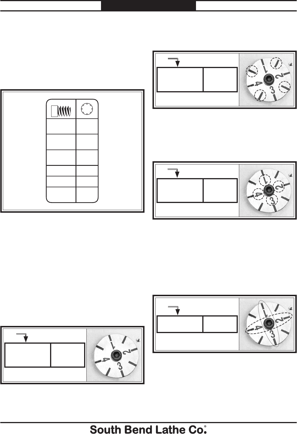
For Machines Mfg. Since 7/09 Model SB1016/SB1036
-57-
OPERATION
Using Thread Dial and Chart
Find the TPI (threads per inch) that you want
to cut in the left column (see Figure 96), then
reference the dial number to the right of it. The
dial numbers indicate when to engage the half
nut for a specific thread pitch. The thread dial
chart can also be found on the front of the thread
dial housing.
4,8,12,16,20,24,
28,32,36,40,44,
48,56,60,72
Any Position
In.
Non-
Numbered
Position
Numbered
Position
1,2,3,4
Position
1,3 or 2,4
Position
1 Only
2,6,10,14,
18,22,26,
30,54
3,5,7,9,
11,13,15,
19,23,27
2½,3½,4½,
7½,11½,13½
2¼,2¾,
3¼,3¾
27⁄8
1
2
3
4
Same as
Metric
Threads
Figure 96. Thread dial chart.
The thread dial is not used for metric, diametral,
or modular pitch threading. You must leave
the half nut lever engaged from the beginning
until the threads are complete for these types of
operations.
The following examples explain how to use the
thread dial chart.
TPI 4-72 Divisible By 4
Use any line (position) on the thread dial, shown
in Figure 97, for threading TPI divisible by four.
Figure 97. Any position marked on the dial can be
used for threading 4-72 TPI.
4,8,12,16,20,24,
28,32,36,40,44,
48,56,60,72
Any Position
TPI 2-54 Not Divisible By 4
Use any of the non-numbered lines on the thread
dial for threading the TPI shown in Figure 98.
TPI
Figure 98. Marks are selected on the dial for threading
2-54 TPI.
Non-
Numbered
Position
2,6,10,14,
18,22,26,
30,54
TPI
Odd Numbered TPI
Use any of the numbered lines on the thread dial
for threading the TPI shown in Figure 99.
Figure 99. Numbers are selected on the dial for
threading odd numbered TPI.
Numbered
Position
1,2,3,4
3,5,7,9,
11,13,15,
19,23,27
TPI
1⁄2 Fractional TPI
Use any opposing number pairs: 1 & 3 or 2 & 4 or
on the thread dial for 1⁄2 fractional TPI (Figure
100). For example, to cut a 31⁄2 thread, select 1
on the dial, then start threading, using 1 or 3 as
your reference points.
Figure 100. Opposing number group are selected on
dial for cutting 1⁄2 thread TPI.
Position
1,3 or 2,4
2½,3½,4½,
7½,11½,13½
TPI
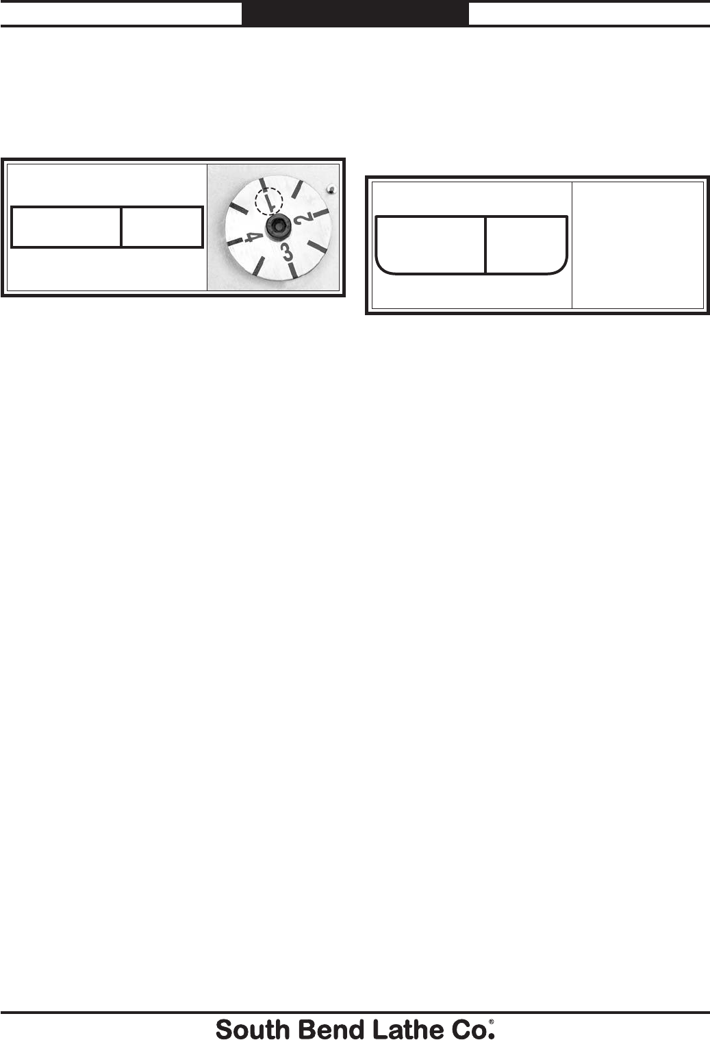
-58-
For Machines Mfg. Since 7/09
Model SB1016/SB1036 OPERATION
Other Fractional TPI
Select one position and always return to that
single position on the thread dial for cutting the
TPI shown in Figure 101. Typically 1 on the
thread dial is selected for ease of memory.
Figure 101. Number 1 on the dial is selected for other
fractional TPI.
Position
1 Only
2¼,2¾,
3¼,3¾
27⁄8 TPI
You cannot use the thread dial when cutting this
thread. The chart indicates that in order to cut
this thread, the process is the same as for cutting
metric threads where the halfnut must stay
engaged until all threading pass are complete.
Figure 102. Cannot use the thread dial for 27⁄8 TPI.
27⁄8Same as
Metric
Threads
Do Not Use
the Thread Dial for
This Thread. Must
Keep the Halfnut
Engaged Untill
this Thread is
Complete
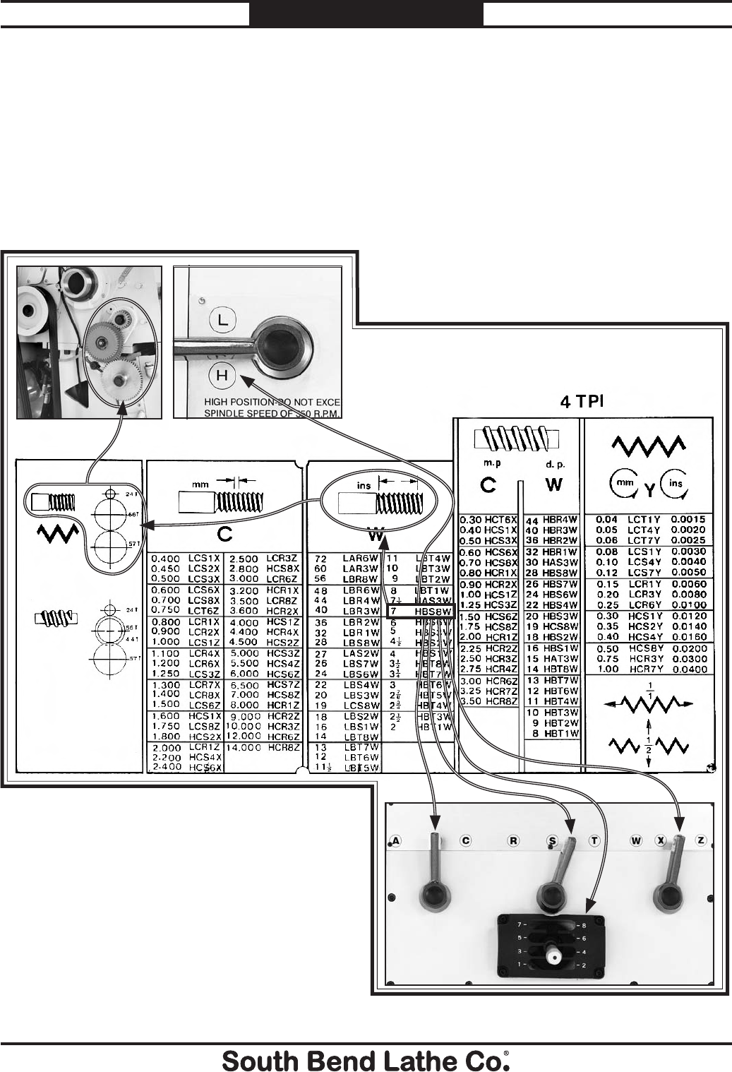
For Machines Mfg. Since 7/09 Model SB1016/SB1036
-59-
OPERATION
Understanding Thread & Feed Rate Chart
A complete threading and feed rate chart is located on the face of the headstock that shows all
available threading and feed configurations for your lathe. Chart use is described below.
Figure 103. Using feed chart with lathe controls.
Positioning Gearbox Levers
To cut a thread or establish a particular feed
rate, you may need to first reposition the
transposing gears located behind the end gear
cover.
Once you have confirmed that the change gears
are positioned according to what the thread and
feed rate charts require, you then can move the
quick change gearbox levers to the required
positions, which are indicated by an alpha-
numeric code on the thread and feed rate chart.
For this example, an inch thread of 7 TPI is
desired. The alpha-numeric code displayed on the
chart shown in Figure 103 is HBS8W.
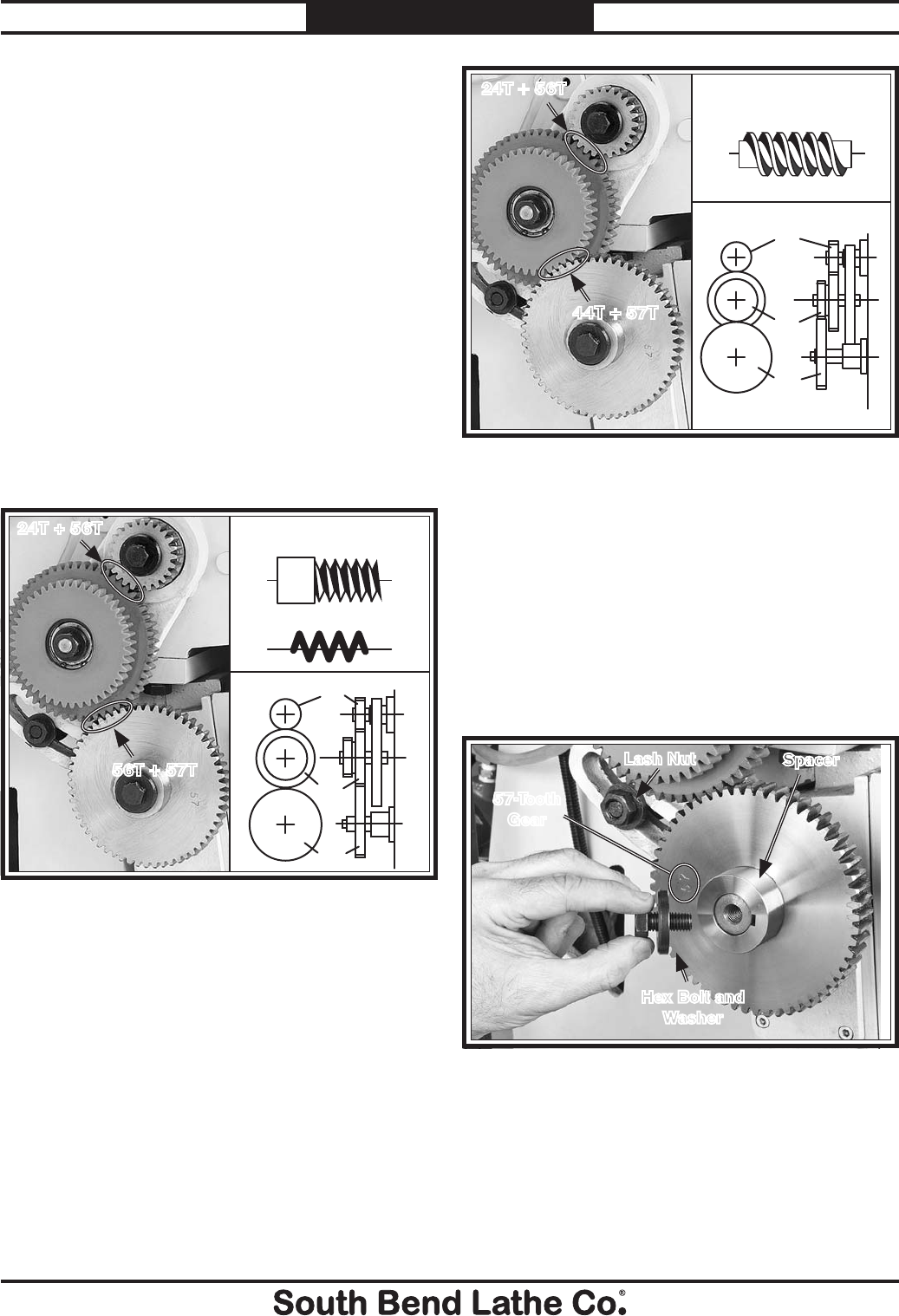
-60-
For Machines Mfg. Since 7/09
Model SB1016/SB1036 OPERATION
Repositioning Change Gears
The factory has arranged the change gears in
the "normal position" so all inch and metric
threading and feed selections are available by
shifting levers. However, if modular or diametral
pitch threading is required, the "alternate
position" must be used. When the gears are
changed they must be cleaned and re-coated with
grease and the gear tooth backlash must reset for
smooth operation.
Normal Position
The 24T change gear is installed in the top
position, the 44T/56T change gears in the middle
position, and the 57T change gear in the bottom
position, as shown in Figure 104. In the normal
position, the 56T and 57T gears are meshed,
which allows for inch and metric threading and
all general feed operations.
Figure 105. Alternate change gear position for
modular and diametral pitch threading.
Configuring Change Gears
1. DISCONNECT LATHE FROM POWER!
2. Shift the gearbox range lever to "Low" so
that the gears will not rotate when the hex
bolt is loosened and retightened.
3. Remove the gear cover, the hex bolt, and the
flat washer shown in Figure 106.
24T + 56T
44T + 57T
24T
44T
57T
Modular and Diametral
Threading Symbol
Figure 106. Removing the change gear.
Spacer
Lash Nut
Hex Bolt and
Washer
57-Tooth
Gear
4. Swap the position of the 57-tooth gear and
spacer, and reinstall the bolt and washer.
5. Use a 23mm wrench to loosen the lash nut,
set the tooth backlash to 0.003"-0.005", and
reinstall the nut and gear cover.
Alternate Position
When the 44- and 57-tooth change gears are
meshed (see Figure 105), the lathe is setup for
modular and diametral pitch turning.
Figure 104. Normal change gear position for inch and
metric threading and feeds.
24T + 56T
56T + 57T
57T
56T
24T
Feed Symbol
Inch and Metric
Threading Symbol
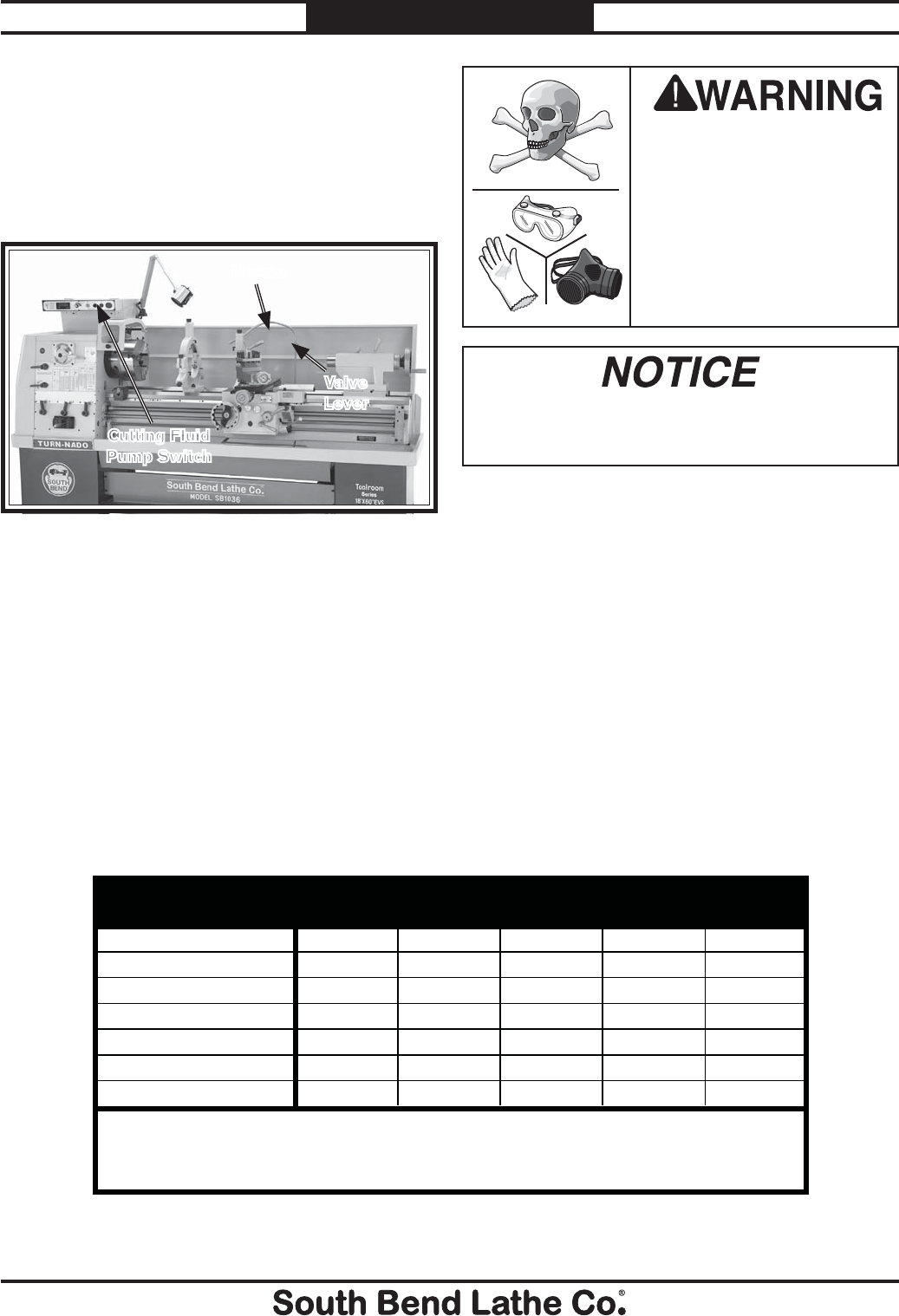
For Machines Mfg. Since 7/09 Model SB1016/SB1036
-61-
OPERATION
To use the cutting fluid system on your lathe:
1. Make sure the tank is properly serviced and
filled with cutting fluid, and that you wear
the necessary personal protection equipment.
2. Position the cutting fluid nozzle for your
operation.
3. Use the control panel cutting fluid pump
switch to turn the cutting fluid pump ON.
4. Adjust the flow of cutting fluid by using the
valve lever near the base of the nozzle hose.
Note: Promptly clean any splashed cutting fluid
from the floor to avoid a slipping hazard.
XX
XXX
XXX X
X
XX
XXXX
XXXX
Aluminum
Brass
Bronze
Cast iron
Low Carbon Steel
Alloy Metals
Stainless Steel
General Note: Cutting fluids are used for heavy-duty lathe operations and production turning. Oil-water
emulsions and synthetic cutting fluids are the most common for typical lathe operations. Sulferized oils
often are used for threading. For small projects, spot lubrications can be done with an oil can or brush, or
omitted completely.
Workpiece Dry Water
Soluble Oil
Synthetic
Coolants
Sulferized
Oil
Mineral
OIl
Figure 108. Cutting Fluid selection table.
BIOLOGICAL & POISON
HAZARD!
Use the correct personal
protection equipment
when handling cutting
fluid. Follow federal, state,
and fluid manufacturer
requirements for proper
disposal.
Cutting Fluid System
A pump delivers cutting fluid through a flex tube
and nozzle. The pump is turned ON/OFF by the
cutting fluid pump switch on the control panel.
Flow is controlled by the valve lever on the flex
tube (see Figure 107).
Always use high quality cutting fluid in this
lathe and follow the manufacturer's instructions
for diluting. The quick reference table shown in
Figure 108 can help you select the appropriate
cutting fluid.
Refer to Cutting Fluid System on Page 73 for
detailed instructions on how to add or change
cutting fluid. Check the cutting fluid regularly
and promptly change it when it becomes overly
dirty or rancid, or as recommended by fluid
manufacturer.
Figure 107. Cutting Fluid system controls and
components.
Cutting Fluid
Pump Switch
Nozzle
Valve
Lever Running the pump without adequate fluid in
the tank may permanently damage it. This is
abuse and is not covered by the warranty.
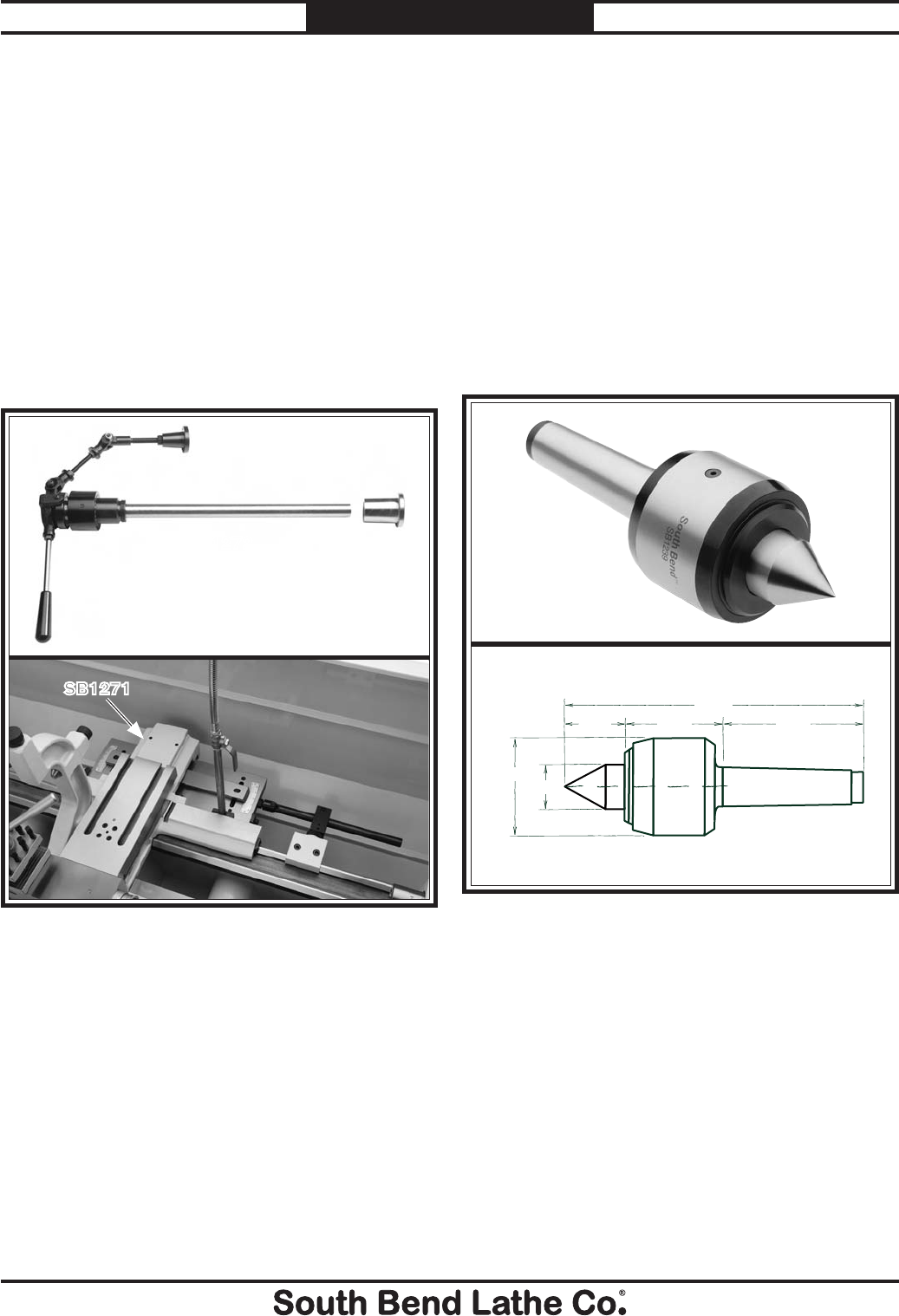
-62-
For Machines Mfg. Since 7/09
Model SB1016/SB1036 ACCESSORIES
Accessories
This section includes the most common
accessories available for your lathe, which may
be available through your local South Bend
Lathe Co. dealer. If you do not have a dealer in
your area, please call us at (360) 734-1540 or
email us at cs@southbendlathe.com.
SB1240—MT#5 High Performance Live Center
South Bend® brand live centers are the best cen-
ters in the industry made with pride and uncom-
promising quality.
s 3HAFTSAREMADEOFALLOYSTEELANDVACUUM
heat treated to HRC60 ± 1 for high rigidity
and durability.
s #ENTERSUSEACOMBINATIONOFROLLERBEARINGS
thrust ball bearings and ball bearings.
s !PPLICABLEFOR#.#LATHESANDHIGHSPEED
turning.
s 7ATERPROOFDESIGN
s CENTERS
SB1271—Taper Attachment for SB1016 &
SB1036 Lathes
SB1272—Collet Attachment 5–C for SB1016 &
SB1036 Lathes
Figure 110. Model SB1239 High Performance Live
Center.
1.73" 2.83" 4.29"
8.86"
2.99"
1.378"
60°
Figure 109. Collet and taper attachments accessories.
SB1271
SB1272
ACCESSORIES
For Machines Mfg. Since 7/09 Model SB1016/SB1036
-63-
ACCESSORIES
SB1298—SBL Bench Lathe Shop Clock
SB1299—SBL Toolroom Lathe Shop Clock
SB1300—SBL Lathe with Man
These fine traditional shop clocks are constructed
with a metal antique-finished frame. They are
easy to read from a distance and measure 14"
in diameter. Pictures just don't do them justice.
They are very nice quality clocks and perfect for
the South Bend Lathe aficionado.
Figure 112. Antique-finished South Bend shop clocks.
SB1298 SB1299
SB1300
Figure 113. Official South Bend Lathe T-Shirts.
SBL Gearhead T-Shirt
SBL One Good Turn T-Shirt
100% Cotton, preshrunk T-shirts, available in
sizes S, M, L, XL, 2XL, 3XL.
Figure 111. Model SB1279 10 Pc. 5-C Collet Set.
SB1279—10 Pc. Precision 5–C Collet Set
Set of 10 collets sized from 1⁄8" - 3⁄4". Same quality
as the individual collets, only packaged in one
convenient set.

MAINTENANCE
-64-
For Machines Mfg. Since 7/09
Model SB1016/SB1036 MAINTENANCE
Always disconnect power
to the machine before
performing maintenance.
Failure to do this may
result in electrocution or
accidental startup injury.
!
Maintenance Schedule
Typically, each operator is responsible for
ensuring proper care of the equipment. We
strongly recommend all operators make a habit
of following the daily maintenance procedures.
For optimum performance from this machine,
this maintenance schedule must be strictly
followed. Use the chart provided on Page 65 to
ensure this is done.
Ongoing
To maintain a low risk of injury and proper
machine operation, if you ever observe any of the
items below, shut down the machine immediately
and fix the problem before continuing operations:
s ,OOSEMOUNTINGBOLTSORFASTENERS
s 7ORNFRAYEDCRACKEDORDAMAGEDWIRES
s 'UARDSREMOVED
s 3TOPBUTTONNOTWORKINGCORRECTLYORNOT
requiring you to reset it before starting the
machine again.
s !REDUCTIONINBRAKINGSPEEDOREFFICIENCY
s (EADSTOCKOILNOTFLOWINGAGAINSTSIGHTGLASS
s #UTTING&LUIDNOTFLOWINGOUTFROMNOZZLE
s Any other unsafe condition.
Daily, Before Operations
s #HECKADDGEARBOXOILPage 69).
s #HECKADDAPRONOILPage 70).
s #HECKCUTTINGmUIDLEVELPage 73).
s ,UBRICATETHEWAYSPage 70).
s 0UTOILINTHEBALLOILERSPage 71).
s #LEANLUBRICATETHELEADSCREWPage 70).
s 4URNSPINDLESPEEDDIALALLTHEWAYDOWN
s -OVETHEPOWERFEEDLEVERONTHEAPRONTO
neutral (to prevent crashes upon startup).
s %NSURECARRIAGELOCKISLOOSE
Daily, During Operations
s 6ERIFYHEADSTOCKOILmOWSWHENPOWERIS
turned ON (Page 66).
Daily, After Operations
s 6ACUUMCLEANALLCHIPSANDSWARFFROMBED
slides, and chip drawer.
s 7IPEDOWNALLUNPAINTEDORMACHINED
surfaces with an oiled rag (Page 71).
s 0USHTHESTOPBUTTONANDSHUTOFF the
master power switch (to prevent accidental
startup).
Monthly
s $RAINANDCLEANTHECUTTINGmUIDTANKTHEN
add new cutting fluid.
Annually (or Semi-Annually with Hard Use)
s $RAINANDCLEANTHEHEADSTOCKOILRESERVOIR
then add new oil.
s #HANGETHEAPRONOIL
s #HANGETHEGEARBOXOIL
s $ISCONNECTMACHINEFROMPOWEROPEN
electrical box, and clean with compressed air
or a vacuum.
Cleaning
Regular cleaning is one of the most important
steps in taking care of this lathe. We recommend
that each operator be responsible for cleaning the
machine immediately after using it or at the end
of the day. We also recommend that the cleaning
routine be planned into the workflow schedule,
so that adequate time is set aside to do the job
right.
Typically, the easiest way to clean swarf from
the bed ways and chip drawer is to use a wet/dry
shop vacuum that is dedicated for this purpose
only. The small chips leftover after vacuuming
can be wiped up with a slightly oiled rag. Avoid
using compressed air to blow off chips, as it may
drive them deeper into moving surfaces and
could cause sharp chips to fly into your face or
hands.
All visible swarf should be removed from the
lathe during cleaning.
For Machines Mfg. Since 7/09 Model SB1016/SB1036
-65-
MAINTENANCE
South Bend Lathe Co.® Monthly Maintenance Chart for EVS Toolroom Series Lathes
12345678910111213141516171819202122232425262728293031
Lubrication
Ways
Ball Oilers
Leadscrew
Unpainted
Surfaces
Inspection
Headstock
Oil Level
Gearbox
Oil Level
Apron Oil
Level
Cutting Fluid
Level
Electrical Box
Fans
Day
Item
Maintenance Chart
Use this chart to keep track of the maintenance performed on your South Bend Lathe. Cross out or initial the “Day” box for each item on the list.
If the box is blacked out, maintenance is not required for that item on that day. Use the maintenance poster included with your South Bend Lathe
as a quick reference guide when performing the maintenance items.
Service Item
Change Gearbox Oil
Change Headstock Oil
Change Apron Oil
Change Cutting Fluid
Annual Service
Once every year, or more often with heavy use,
perform these service items. Keep track of when you
last performed your annual service and when you’ll
need to perform it again.
Make copies of this page to use each month. Keep each chart as a maintenance record for your South Bend Lathe.
Date of last annual service:
Date of next annual service:
s&!8
www.southbendlathe.com
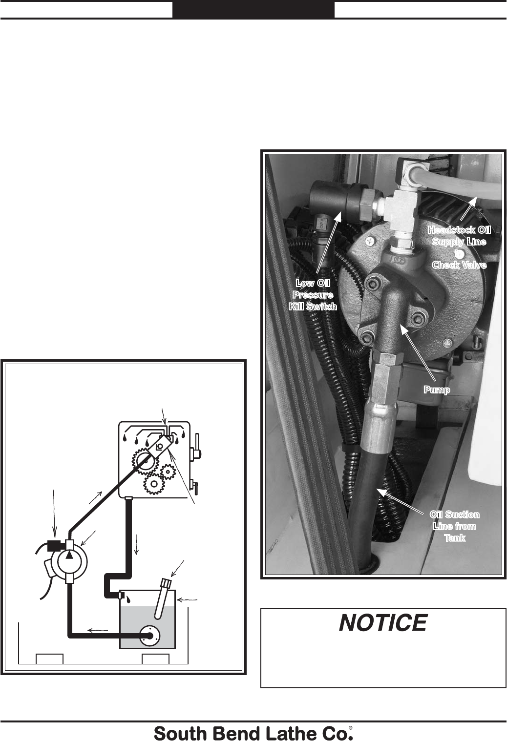
-66-
For Machines Mfg. Since 7/09
Model SB1016/SB1036 MAINTENANCE
Lubrication
Headstock
The headstock has a pressurized lubrication
system that consists of an oil pump, a low oil
pressure kill switch, a supply tank, oil hoses,
and a manifold with oil distribution lines. The
headstock has a series of oil lines that direct oil
to key locations, such as the spindle bearings
and upper headstock gearing, to ensure that
they always remain well lubricated, (especially
when low-speed high-load lathe operations could
potentially starve the upper headstock of oil).
The oil pump automatically turns ON and
begins oiling the headstock components when
the master power switch is turned ON and the
stop button is reset. The oil is pumped before the
spindle is started to protect the spindle bearings
against potential damage from dry starts.
Review the lubrication system diagram shown
in Figure 114 to familiarize yourself with the
function and relationship of the components.
Oil Pressure Safety Switch
To prevent costly damage to the headstock
gears and bearings, an oil pressure kill switch
shown in Figure 115 is installed on the output
side of the pump and will shut the lathe down
if oil pressure is lost for any reason. Verify that
the pump works by looking into the sight glass
shown in Figure 116, and observing the oil flow.
Suction
Supply
Return
One Way
Check Valve
Pump
and
Motor
Tank
Oil Pressure
Kill Switch
Headstock
Oil Distribution
Manifold and Lines
Fill Spout
with
Dipstick
Figure 114. Lubrication system overview.
Figure 115. Oil pump and oil pressure safety switch.
Oil Suction
Line from
Tank
Pump
Low Oil
Pressure
Kill Switch
Never bypass this switch to force the lathe
to run. If you do, headstock gear and bearing
damage will occur if headstock components
operate without lubrication.
Headstock Oil
Supply Line
to
Check Valve
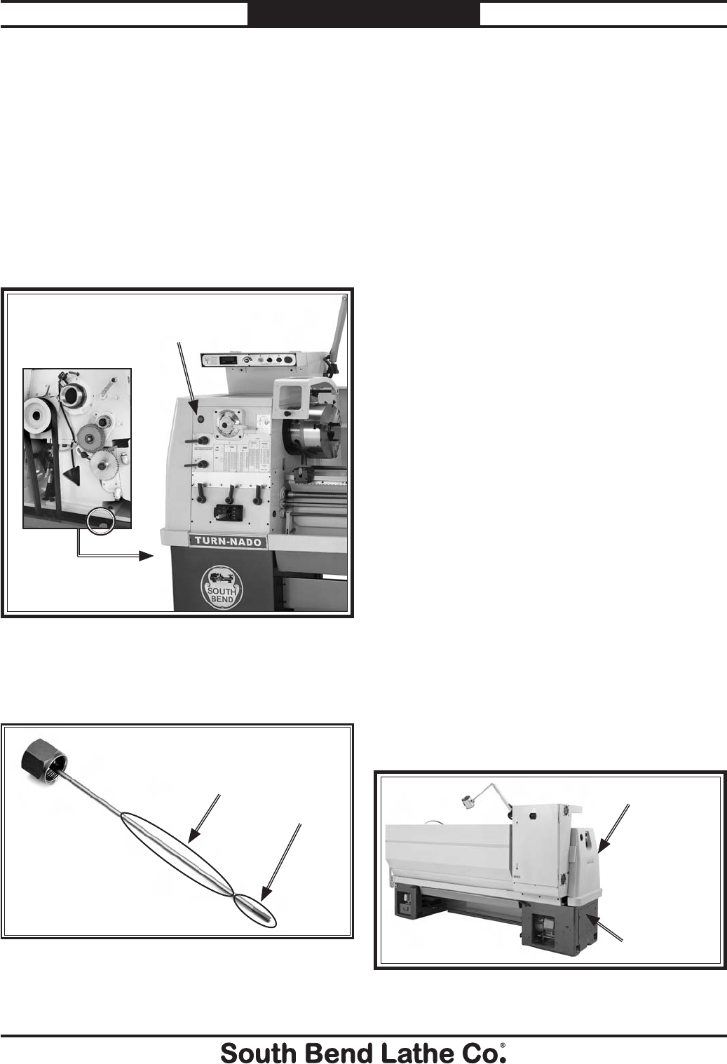
For Machines Mfg. Since 7/09 Model SB1016/SB1036
-67-
MAINTENANCE
Checking & Adding Oil
Oil Type...Mobil DTE Light or ISO 32 Equivalent
Oil Amount .............................................. 4 Gallons
Check/Add Frequency .................................... Daily
Change Frequency ...................................Annually
The oil sight glass shown in Figure 116 is to
verify that oil is being pumped into the headstock
during operation. When the lathe is disconnected
from power, no oil will be seen in the sight glass.
Adding oil is done at the oil tank filler cap shown
in Figure 119.
Changing Headstock Oil
The headstock oil pump system must be cleaned
and the oil changed after the break-in period and
then annually (or every six months with hard
service or extreme working conditions).
Since this lathe uses a base-mounted oil tank,
removing a drain plug and using a drain pan
is not an option when draining the oil. We
recommend using a remote oil pump with a
suction hose that can be inserted through the
filler spout to the bottom of the oil tank instead.
If a remote oil pump system is not available,
use the headstock oil pump for this purpose, as
outlined below.
Items Needed: Qty
5-Gallon Waste Oil Bucket with Lid .................... 1
Phillips Screwdriver #2 ........................................1
Standard Screwdriver #2 ......................................1
Funnel 8" ............................................................... 1
Hex Wrench 4mm .................................................1
Wrench 17mm ....................................................... 1
Wrench 25mm ....................................................... 1
Wrench 1
1⁄2" ...........................................................1
Mineral Spirits ................................... As Required
Rags .................................................... As Required
Gasket or Automotive Silicone Sealant ...............1
Hose Clamp .................................................1⁄2" Dia.
Rubber Drain Hose ....................... 3⁄8" ID x 4' Long
Magnets .................................................... Optional
To to change the headstock oil:
1. DISCONNECT LATHE FROM POWER!
2. Remove the end gear cover, the tank cover
(see Figure 118), and remove the oil tank
filler cap (see Figure 119).
Figure 118. Tank cover plate removed.
Tank Cover
End Gear Cover
The oil tank filler cap is fitted with a dip stick
for checking the headstock oil level as shown in
Figure 117.
Figure 117. Headstock oil level dip stick.
Full Zone
Add Zone
Figure 116. Headstock oil flow sight glass location.
Headstock Oil
Flow Sight Glass.
Tank Filler Cap
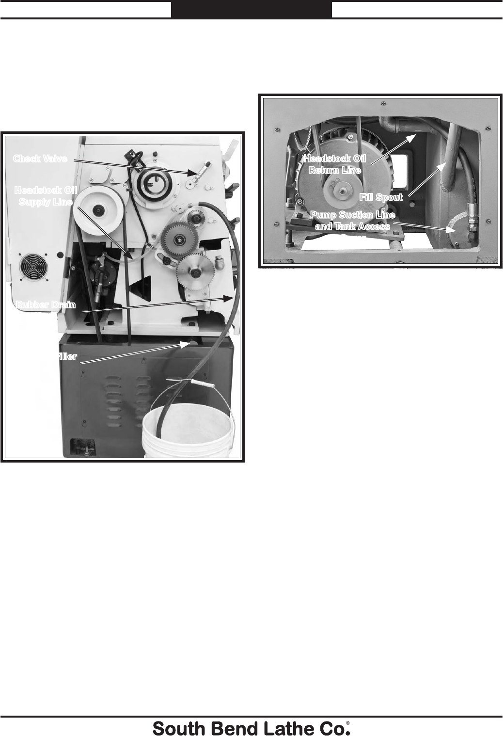
-68-
For Machines Mfg. Since 7/09
Model SB1016/SB1036 MAINTENANCE
5. Hold the other end of the drain tube in the
bucket, and turn ON the master power
switch located on the electrical box door. The
old headstock oil will be pumped from the
tank and into the bucket.
6. As soon as you hear a sucking sound from
the tank, or when the oil slows or stops
flowing out, turn the master power switch
OFF to stop the pump.
7. Remove the rubber drain hose and reconnect
the headstock oil supply line to the check
valve.
3. Remove the headstock oil supply line from
the check valve, as shown in Figure 121.
4. Push the rubber drain hose onto the
headstock oil supply line, as shown in
Figure 119. Use a hose clamp if required to
ensure a tight connection.
8. Place a series of rags under the tank access
cover to catch the residual oil in the tank
when the tank access cover shown in Figure
120 is removed.
FPO: SB1036 Motor and Pump
Fill Spout
Figure 120. Location of tank.
Pump Suction Line
and Tank Access
Cover
9. Remove the pump suction line from the tank.
10. Remove the three access cover cap screws,
and carefully remove the cover.
11. Using mineral spirits and rags, wipe down
the inside of the tank including any baffles
and screens until all are clean. Make sure
to soak up any excess mineral spirits with
dry rags, so it does not stay in the tank and
contaminate the oil.
Tip: Consider placing one or two magnets at the
bottom of the tank to collect any fine metal
particles generated by the headstock drive
train. This will make cleaning easier the
next time around and ensure that more
metal particles are kept out of the headstock
oil.
12. Reinstall the access plate with a new gasket
or silicone sealant.
13. Place the funnel in the fill spout and add
the new oil. Refer to Page 66 for the
recommended type and amount of oil to use.
14. Test pump operation, recheck the oil level,
and reinstall the covers.
Headstock Oil
Return Line
Figure 119. Changing headstock oil.
Headstock Oil
Supply Line
Rubber Drain
Hose
Oil Tank Filler
Cap
Check Valve
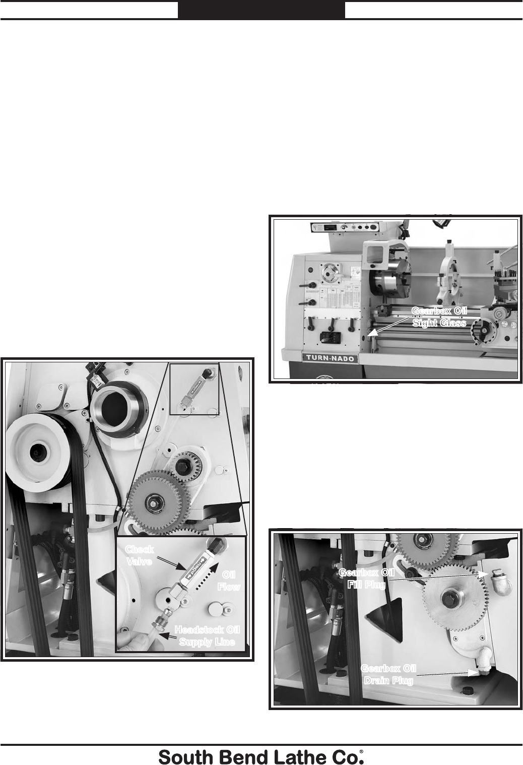
For Machines Mfg. Since 7/09 Model SB1016/SB1036
-69-
MAINTENANCE
Priming the Oil Pump
The lubrication system is also equipped with a
check valve that is shown in Figure 121. This
valve allows oil to flow to the headstock during
pump operation, but prevents the oil from
draining back into the tank and the pump from
losing its prime when not in operation. However,
if after long-term storage, or if the machine is
being started for the first time in test run, we
recommend that the pump and line be primed
with oil to prevent a dry run.
Items Needed: Qty
Pump-Type Oil Can Filled with Headstock Oil ... 1
Wrench 17mm ....................................................... 1
To prime the oil pump:
1. DISCONNECT LATHE FROM POWER!
2. Remove the end gear cover.
3. Remove the headstock oil supply line from
the check valve, as shown in Figure 121.
4. Fill the supply line with oil, reinstall, and
test pump operation and verify oil flow.
Figure 121. Priming location and check valve.
Change
Gears
Headstock Oil
Supply Line
Oil
Flow
Check
Valve
Figure 123. Location of gearbox fill and drain plugs.
Gearbox Oil
Fill Plug
Gearbox Oil
Drain Plug
Quick Change Gearbox
Oil Type ...... Mobil Vactra 2 or ISO 68 Equivalent
Oil Amount ............................................ As Needed
Check/Add Frequency .................................... Daily
Change Frequency ...................................Annually
Checking & Adding Oil
The sight glass shown in Figure 122 shows the
oil level in the gearbox. At the full level, the oil
fills approximately 3⁄4 of the sight glass. At the
add level, the oil fills 1⁄4 of the sight glass or less.
Check the oil level daily.
Figure 122. Gearbox sight glass location.
Gearbox Oil
Sight Glass
Changing Oil
The gearbox oil must be changed after the
break-in period and then annually (or every six
months with hard service or extreme working
conditions). Figure 123 shows fill and drain
plugs used when changing the gearbox oil. The
fill plug is removed with a 20mm wrench, and
the drain plug is removed with a 16mm wrench.
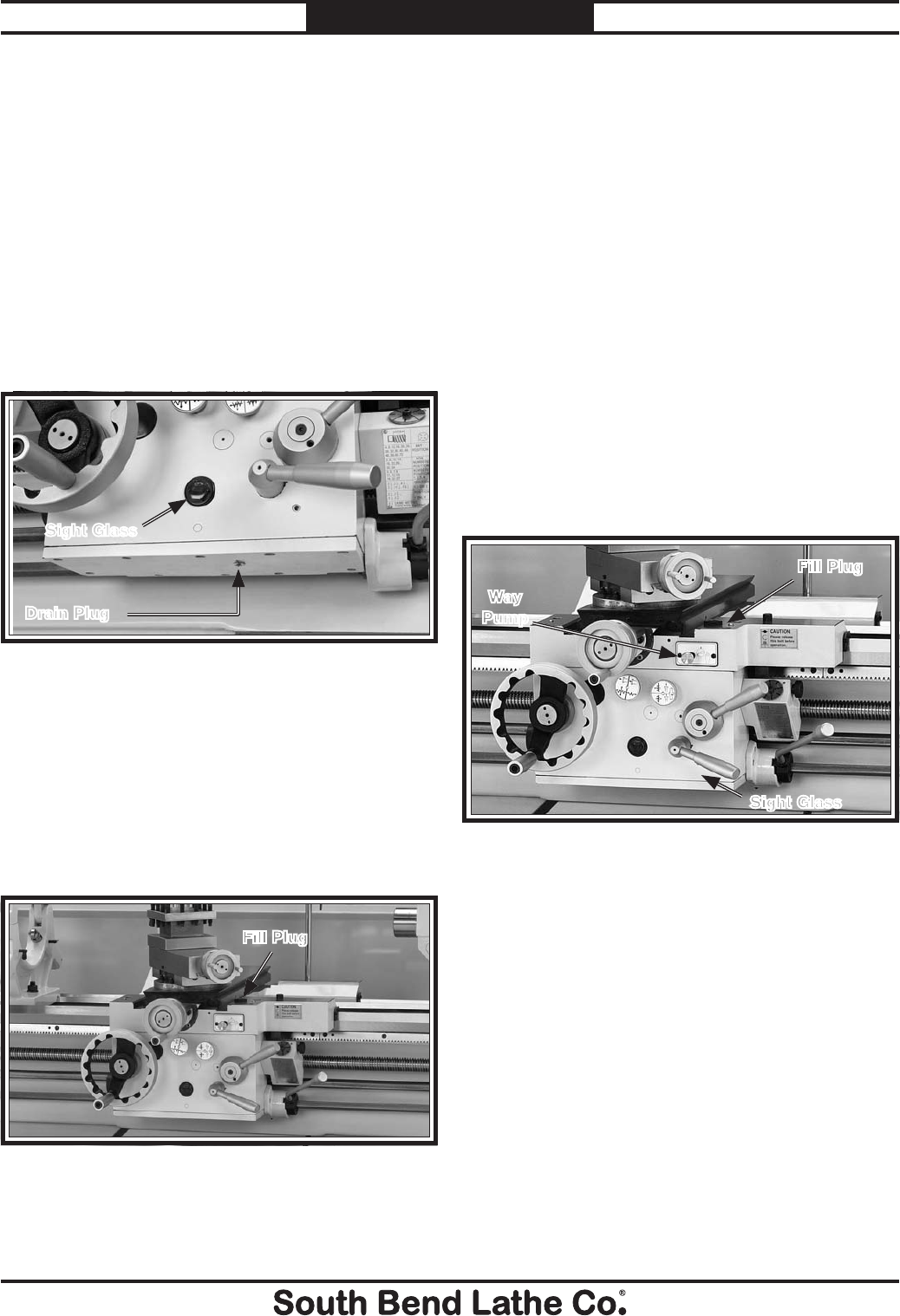
-70-
For Machines Mfg. Since 7/09
Model SB1016/SB1036 MAINTENANCE
Apron
Oil Type ...... Mobil Vactra 2 or ISO 68 Equivalent
Oil Amount ............................................ As Needed
Check/Add Frequency .................................... Daily
Change Frequency ...................................Annually
Checking & Adding Oil
The sight glass shown in Figure 124 shows
the oil level in the apron. At the full level, the
oil fills approximately 3⁄4 of the sight glass. At
the add level, the oil fills 1⁄4 of the sight glass or
less. Check the oil level daily and after using the
apron oil pump.
Changing Oil
The oil in the apron reservoir must be changed
after the break-in period and then annually (or
every six months with hard service or extreme
working conditions). The drain plug is shown in
Figure 124 is removed with a 6mm hex wrench,
and the knurled fill plug is shown in Figure
125 is removed by hand.
Figure 125. Location of fill plug for apron oil reservoir.
Fill Plug
Figure 124. Location of apron drain plug & sight glass.
Drain Plug
Sight Glass
Ways & Slides
The way pump shown in Figure 126 lubricates
the saddle and cross slide way guides with the oil
from the apron reservoir.
Figure 126. Location of way pump and sight glass.
Sight Glass
Fill Plug
Way
Pump
Lead Screw
Oil Type ...... Mobil Vactra 2 or ISO 68 Equivalent
Oil Amount ............................................ As Needed
Lubrication Frequency ................................... Daily
Before lubricating the leadscrew, clean it first
with mineral spirits. A paint brush works well
to help clean out the threads. Make sure to move
the carriage out of the way, so you can clean the
entire length of the leadscrew.
Apply a thin coat of oil along the length of the
leadscrew. Use a paint brush to make sure the
oil is evenly applied and down in the threads.
To use the way pump to lubricate the ways, pull
the pump knob out for two or three seconds and
then push it in. The pump draws oil from the
apron reservoir and then forces it through drilled
passages to the way guides.
Repeat this process and move the carriage left/
right and the cross slide forward/backward to
distribute oil along the way guides.
Lubricate the guides once before and once after
operating the lathe. If the lathe is in a moist
or dirty environment, increase the lubrication
interval and make sure to keep the oil level full.
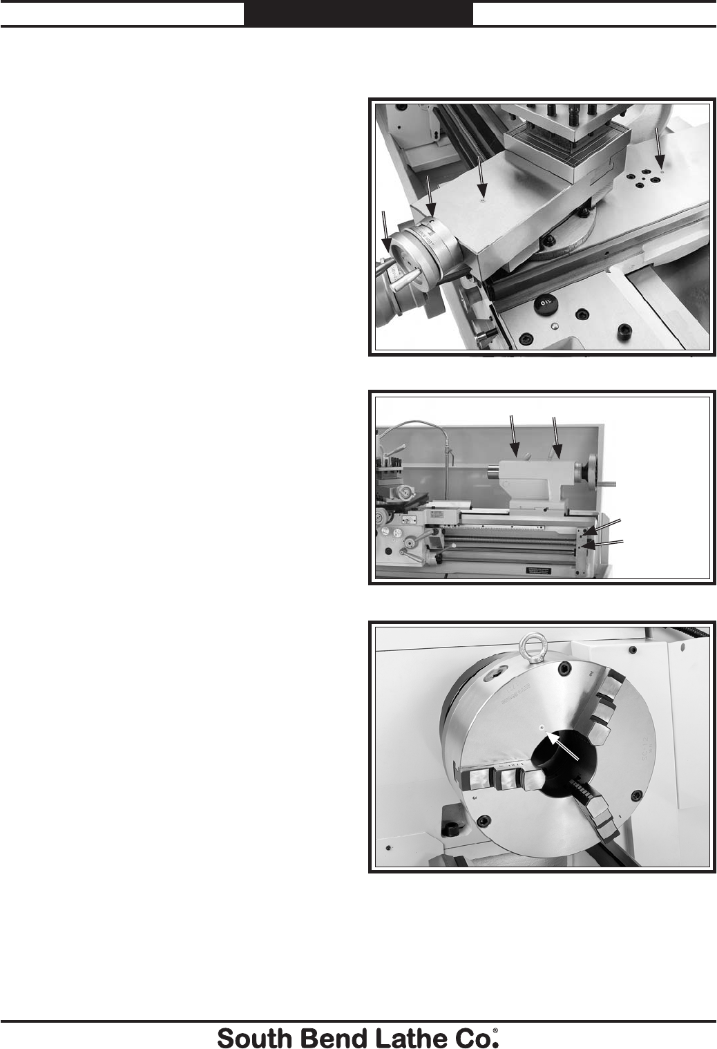
For Machines Mfg. Since 7/09 Model SB1016/SB1036
-71-
MAINTENANCE
Unpainted & Machined Surfaces
Besides the ways and leadscrew, all other
unpainted and machined surfaces should be
wiped down daily to keep them rust-free and in
top condition. This includes the top of the saddle,
the cross slide, compound slide, tool post, chuck,
feedrod, and any other surface you can find that
could be vulnerable to rust if left unprotected
(this especially includes any parts that may be
exposed to water soluble cutting fluids). Typically
with these parts, a thin film of oil is all that
is necessary for protection. Any quality metal
protectant can be used to protect machined
surfaces, including either of the oils you use
elsewhere in the lathe.
Ball Oilers
Oil Type ...... Mobil Vactra 2 or ISO 68 Equivalent
Oil Amount .......................................... As required
Pump Oil Can w/Plastic or Rubber Cone Tip ...... 1
Lubrication Frequency ......... Before and After Use
Proper lubrication of ball oilers is done with
a pump-type oil gun that has a plastic or
rubberized cone tip. Metal needle or lance tips
are not recommended as they do not create a
good seal. These tips usually push the ball too
far into the oiler, break the spring seat, and
sometimes cause the ball to fall into the oil
galley.
Lubricate the ball oilers before and after use
machine use, and more frequently under heavy
use. When lubricating ball oilers, clean the
outside surface to remove any dust or grime.
Push the rubber or plastic tip of the oil can
nozzle against the ball oiler to create a hydraulic
seal, and pump the oil can once or twice. If
sludge and contaminants are seen being pushed
out of the lubrication area, keep pumping the oil
gun until clean oil is seen. When finished, wipe
away the contaminants and oil.
Never blow out ball oilers or oil galleys with an
air gun to purge the system of contaminants.
Air pressure can force contaminants into
unreachable areas and dislodge seals and blow-
out gaskets.
Figure 127. Four ball oiler locations.
Figure 128. Four ball oiler locations.
Figure 129. Ball oiler location for 3-Jaw chuck.
This lathe has five ball oiler locations (see
Figures 127–129).
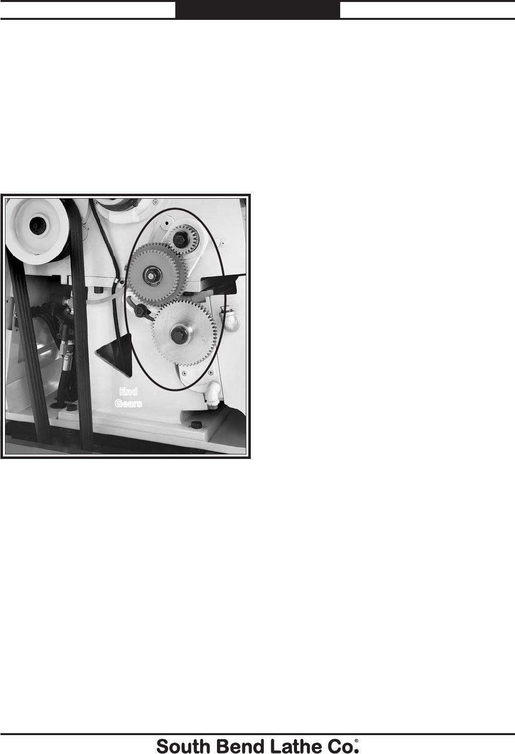
-72-
For Machines Mfg. Since 7/09
Model SB1016/SB1036 MAINTENANCE
Change Gears
Grease Type ............................................... NLGI#2
Frequency ................Annually or When Swapping
The change gears, shown in Figure 130, should
always have a thin coat of heavy grease to
minimize corrosion, noise, and wear. Care must
be taken to avoid over-greasing because excess
grease will be flung onto the V-belts, which
will cause the belts to slip and the lathe to lose
power.
Figure 130. Location of change gears that require
grease.
End
Gears
Handling & Care
Make sure to clean and lubricate any gears you
install or swap. Unless you are very careful
during handling and storage, the coating of
grease on the gears will easily pickup dirt or
debris, which can then spread to the other gears
and increase the rate of wear.
Make sure the cover remains installed whenever
possible to keep the gears free of dust or debris
from the outside environment.
Lubricating
1. DISCONNECT LATHE FROM POWER!
2. Remove the end gear cover.
3. Clean the change gears thoroughly with
mineral spirits to remove all the old grease.
Use a small brush if necessary to clean
between the teeth.
4. Clean the shafts from which the end gears
were removed, and wipe up any old grease
splatters in the vicinity and on the inside of
the headstock cover.
5. With clean hands, apply a thin layer of
grease on the gears. Make sure to get grease
between the gear teeth, but not so much that
it fills the voids between the teeth.
6. Install the end gears and mesh them
together with an approximate backlash of
0.005". Once the gears are meshed together,
apply a small dab of grease in the crux of
where the gears mesh together—this grease
will spread around when the gears start
moving and re-coat any areas scraped off
during installation.
Annual Maintenance
Once a year, remove all the change gears, clean
them thoroughly, and apply a new coating of
grease. Even if the end gear cover has been kept
in place throughout the year, it is still possible
for dust from the V-belts to build-up in the
grease, and the grease may also start to break
down with extended or heavy use.

For Machines Mfg. Since 7/09 Model SB1016/SB1036
-73-
MAINTENANCE
Cutting Fluid System
The cutting fluid system holds 6
1⁄2 gallons. A
pump pulls fluid from the tank and sends it to
the valve, which controls the flow of cutting fluid
through a universal hose and nozzle. When the
valve is opened or closed, the fluid flows from the
nozzle and drains into the chip drawer and into
a catch tray that directs it back into the tank.
Figure 131 shows many of these components
and their locations.
When swarf from machining operations falls
into the chip drawer, most of it will stay there.
However, some fine metal particles and chips
are suspended by the cutting fluid and will wash
into the tank via the catch tray. Once in the
tank, these fine metal particles and shavings will
settle, and cleaner cutting fluid will be drawn in
by the pump.
Keep in mind that the metal particles from many
types of metal sit at the bottom of the tank and
the fluid can become very toxic and poisonous.
To maintain safety and pump life, cleaning the
system on a regular basis is mandatory.
Figure 131. Cutting Fluid system components and
locations.
Nozzle
Pump Switch
Valve
Vented Tank Cover Removed
for Pump & Tank Access
Chip
Drawer
Catch Tray
BIOLOGICAL & POISON
HAZARD!
Use the correct personal
protection equipment
when handling cutting
fluid. Follow federal, state,
and fluid manufacturer
requirements for proper
disposal.
Adding Fluid
1. DISCONNECT LATHE FROM POWER!
2. Remove the vented tank cover to access the
cutting fluid tank (see Figure 131) and
observe the fluid level in the tank when
adding fluid.
3. Pour your pre-mixed cutting fluid in the
chip drawer until the tank is nearly full and
reinstall the vented cover.
Hazards
As some cutting fluid ages, dangerous microbes
can proliferate and create a biological hazard.
The risk of exposure to this hazard can be greatly
reduced by replacing the old cutting fluid as
indicated by the fluid manufacturer.
The important thing to keep in mind when
working with cutting fluid is to minimize
exposure to your skin, eyes, and respiratory
system by wearing the proper PPE (personal
protection equipment), such as splash-resistant
safety glasses, long-sleeve gloves, protective
clothing, and a NIOSH approved respirator.
Splash Guard
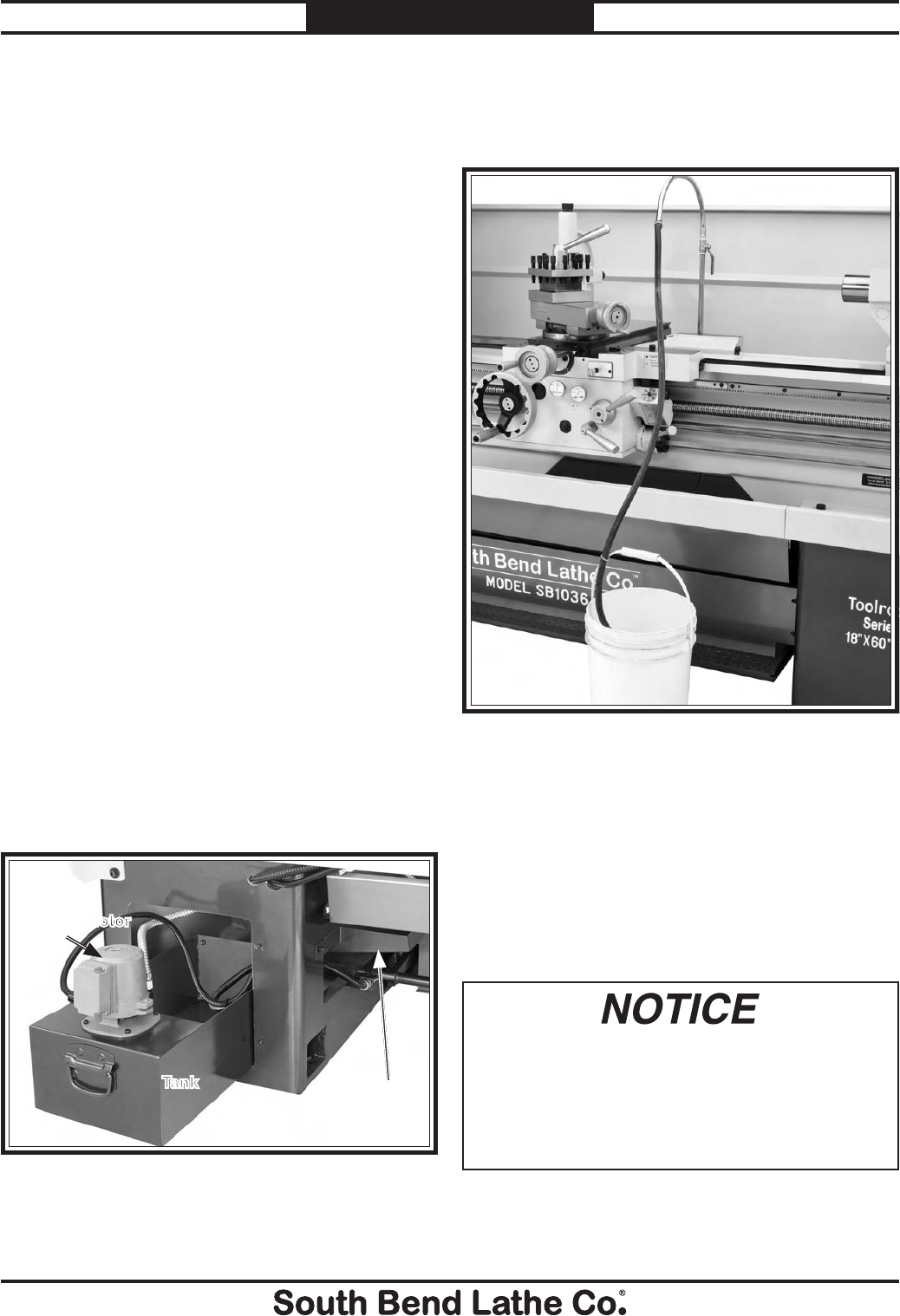
-74-
For Machines Mfg. Since 7/09
Model SB1016/SB1036 MAINTENANCE
Changing Cutting Fluid
When you replace the old cutting fluid, take
the time to thoroughly clean out the chip
drawer, catch tray, and chip drawer. Make
sure to dispose of all old fluid according to
local regulations. Cutting fluid is considered
hazardous waste by the EPA. Follow all disposal
and storage guidelines when changing and
disposing of cutting fluid.
Tip: Maintaining the specific gravity of cutting
fluid with a basic hydrometer or economical
refractometer can greatly extend the life of
cutting fluid, to maintain cutting fluid properties
for cutting and reduce operating costs through
longer tool life.
Items Needed: Qty
Safety Wear ......See Hazards section on Page 73
New Cutting Fluid ............................... 6
1⁄2 Gallons
Five Gallon Drain Buckets w/Lids .......................2
Phillips Screwdriver #2 ........................................1
Wrench 3⁄4" .............................................................1
Shop Rags ........................................... As Required
Rubber Hose 1⁄2" ID x 60" Long ................ Optional
Magnets .................................................... Optional
To change the cutting fluid:
1. Clean out the chip drawer.
2. Remove the vented tank cover. Lift and slide
the pump and tank out of the cabinet as
shown in Figure 13130.
3. Connect the rubber hose to the end of the
cutting fluid nozzle as shown in Figure 131.
If the connection is questionable, use a hose
clamp to ensure it does not leak.
Figure 133. Cutting Fluid drain hose connection.
4. Insert the other end of the hose into the
bucket and secure it from falling out with a
piece of wire when the pump is turned on.
5. Open the flow lever all the way, and turn
the cutting fluid pump ON. Do not leave the
area as you will need transfer the hose to
the other bucket to prevent over-filling and
spillage.
Leaving the pump running with and empty
cutting fluid tank can damage the pump. Shut
the pump OFF immediately when the fluid
slows or stops coming from the drain hose.
Otherwise, any pump damage is not covered
under warranty.
6. When the fluid stops flowing, immediately
turn OFF the pump, and disconnect the
drain hose.
Figure 132. Tank location for cleaning.
Tank
Pump Motor
Drain
Trough
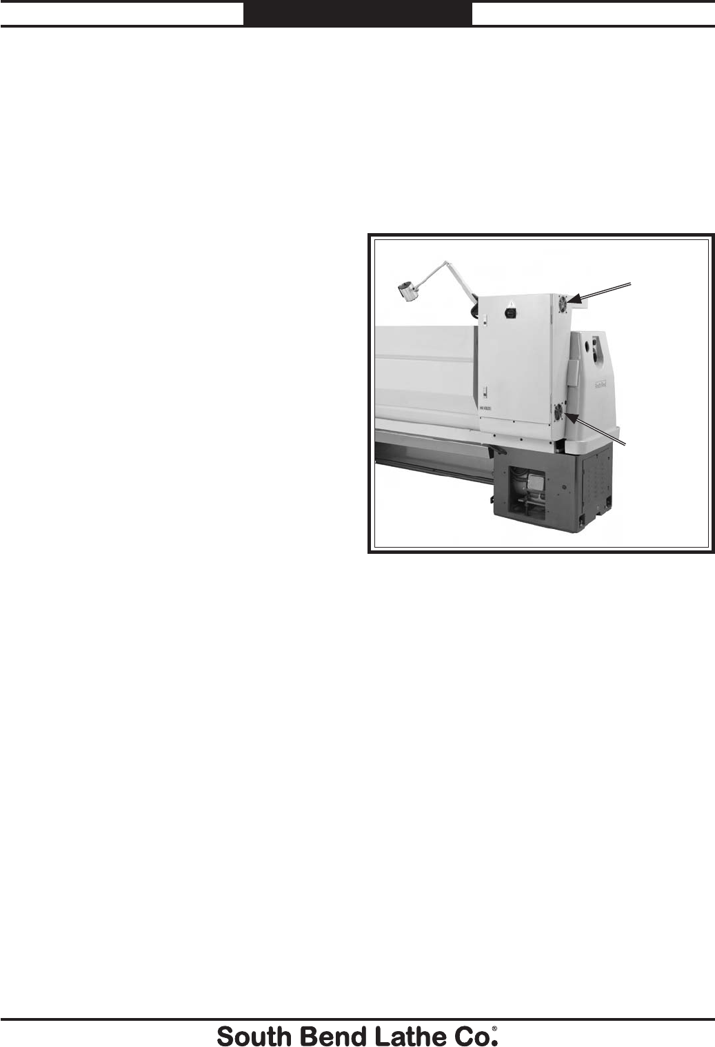
For Machines Mfg. Since 7/09 Model SB1016/SB1036
-75-
MAINTENANCE
8. Pour out the remaining cutting fluid from
the tank into the 5-gallon bucket and seal
the bucket with its lid.
9. Lift and slide the tank out far enough for
cleaning.
10. Using mineral spirits and rags, clean and
dry the tank. If a water soluble cutting fluid
was used, use soap and hot water instead of
mineral spirits.
Tip: Leave one or more strong magnets at the
bottom of the tank to collect fine metal
particles from the cutting fluid.
11. Reinstall the tank and cover.
12. Mix the new cutting fluid to the required
specific gravity as specified by the cutting
fluid manufacturer.
13. Pour 6
1⁄2 gallons of cutting fluid into the chip
drawer.
14. CONNECT LATHE TO POWER.
15. Point the cutting fluid nozzle into the chip
drawer and open the valve.
16. Turn the cutting fluid pump ON to verify
that fluid cycles properly, then turn it OFF.
Cleaning Electrical Box
The electrical box has two cooling fans (Figure
134) for the electrical box. The lower fan draws
in cool air and the upper fan exhausts warm
air. Frequently verify that the cooling fans work
and the blades are free of debris and dust that
can cause the fans to run out of balance. An
overheated electrical box could result in damage
to the electrical components inside of the box.
To clean the fans and electrical box:
1. DISCONNECT LATHE FROM POWER!
2. Put on a dust mask and safety goggles.
3. Open the electrical box door.
4. Holding an air gun nozzle 24" away from the
electrical components, blow dust off of the
components and out of the box.
5. Close electrical box door and verify fan
operation.
Figure 134. Electrical box cooling fans.
Inlet Fan
Outlet
Fan

-76-
For Machines Mfg. Since 7/09
Model SB1016/SB1036 MAINTENANCE
Machine Storage
If the machine is not properly prepared for
storage, it may develop rust or corrosion. If
decommissioning this machine, use the steps
in this section to ensure that it remains in
good condition for later use.
To prepare your machine for short-term
storage (up to a year):
1. Pump out the old cutting fluid, and remove
and blow out lines with compressed air and a
few drops of way oil.
2. DISCONNECT LATHE FROM POWER!
3. Thoroughly clean all unpainted, bare metal
surfaces, then apply a liberal coat of way oil.
4. Lubricate the machine as outlined in the
lubrication section. Be sure to use the oil gun
to purge all ball oilers and the oil passages
with fresh oil.
5. Cover and place the machine in a dry area
that is out of direct sunlight and away from
hazardous fumes, paint, solvents, or gas.
Fumes and sunlight can bleach or discolor
paint and make plastic guards cloudy.
6. Once or twice a month, depending on the
ambient humidity levels in the storage
environment, wipe down the machine as
outlined in Step 3. Slide the carriage,
micrometer stop, tailstock, and steady rest
down the lathe bed to make sure that way
spotting is not beginning to occur.
7. Every few months, by hand rotate all gear-
driven components a few times in several
gear selections. This will keep the bearings,
bushings, gears, and shafts well lubricated
and protected from corrosion, especially
during the winter months.
To prepare your machine for long-term
storage (a year or more):
1. Run the lathe and bring all gearboxes to
operating temperature, then drain and refill
the all gearboxes with fresh oil.
2. Pump out the old cutting fluid, and remove
and blow out lines with compressed air and a
few drops of way oil.
3. DISCONNECT LATHE FROM POWER!
4. Thoroughly clean all unpainted, bare metal
surfaces, then apply a liberal coat of way oil,
a heavy grease, or rust preventative. Take
care to ensure these surfaces are completely
covered but that the rust preventative or
grease is kept off of painted surfaces.
5. Lubricate the machine as outlined in the
lubrication section. Be sure to use the oil gun
to purge all ball oilers and the oil passages
with fresh oil.
6. Loosen or remove machine belts so they do
not become stretched during the storage
period. (Be sure to also affix a maintenance
note near the power button as a reminder
that the belts have been loosened or
removed.)
7. Place a few moisture absorbing desiccant
packs inside of the electrical box.
8. Cover and place the machine in a dry area
that is out of direct sunlight and away from
hazardous fumes, paint, solvents, or gas.
Fumes and sunlight can bleach or discolor
paint and make plastic guards cloudy.
9. Slide the carriage, micrometer stop,
tailstock, and steady rest down the lathe
bed to make sure that way spotting is not
beginning to occur.
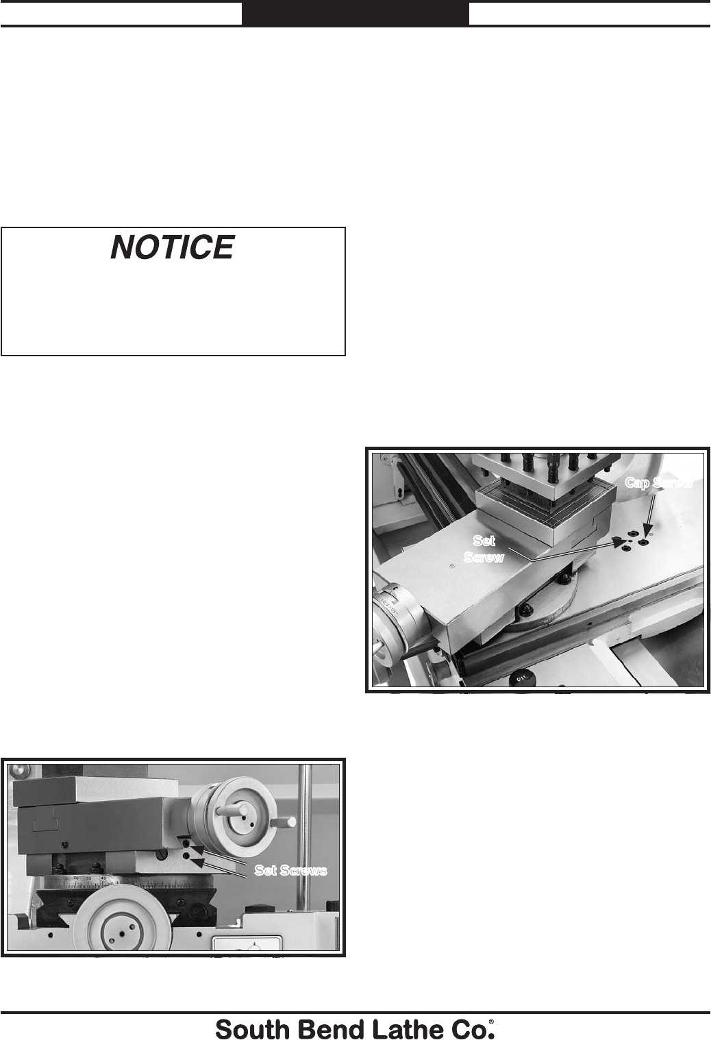
SERVICE
For Machines Mfg. Since 7/09 Model SB1016/SB1036
-77-
SERVICE
Backlash Adjustment
Figure 136. Cross slide backlash adjustment screws.
Cap Screw
Set
Screw
Cross Slide Leadscrew
Tools Needed: Qty
Hex Wrench 3mm .................................................1
Hex Wrench 6mm ................................................1
Backlash is adjusted by loosening all four
cap screws shown in Figure 136, and then
tightening the center set screw, which pushes
down on a wedge and forces the nut apart, taking
up lash in the nut and leadscrew.
If you end up adjusting the nut too tight, loosen
the set screw, tap the cross slide a few times with
a rubber or wooden mallet, and turn the handle
slowly back-and-forth, until the handle turns
freely.
To re-adjust the backlash, rock the handle back
and forth and tighten the set screw slowly until
the backlash is at approximately 0.001" as
indicated on the handwheel dial.
Backlash is the amount of free play felt
while switching rotation directions with
the handwheel. This can be adjusted on the
compound and cross slide leadscrews. Before
beginning any adjustment, make sure that all
associated components have been cleaned and
re-lubricated.
Compound Leadscrew
Tools Needed: Qty
Hex Wrench 4mm .................................................1
Backlash is adjusted by tightening the set screws
shown in Figure 135. When these screws are-
adjusted against the leadscrew nut, they offset
part of the nut to remove play between the nut
and leadscrew.
If you end up adjusting the nut too tight, loosen
the set screws, tap the compound a few times
with a rubber or wooden mallet, and turn the
handle slowly back and forth until it moves
freely.
To readjust the backlash, rock the handle back
and forth, and tighten the screws slowly until the
backlash is at approximately 0.001" as indicated
on the handwheel dial.
Reducing backlash to less than 0.001"
is impractical. Avoid the temptation to
overtighten the backlash set screw while
adjusting. Overtightening leads to accelerated
wear of the wedge, nut, and leadscrew.
Figure 135. Compound slide backlash adjustment
screws.
Set Screws
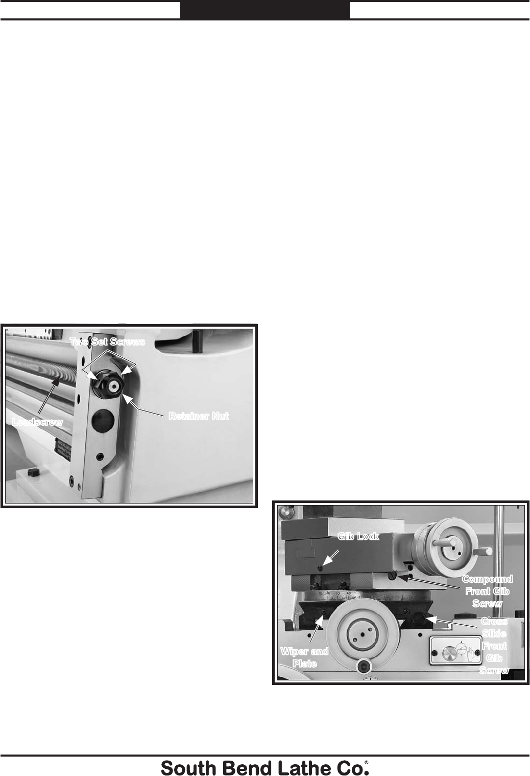
-78-
For Machines Mfg. Since 7/09
Model SB1016/SB1036 SERVICE
After a long period of time, you may find that the
leadscrew develops a small amount of end play.
This lathe is designed so that leadscrew end play
can be easily removed with adjustment.
Tools Needed: Qty
Open End Wrench 36mm or 1
7⁄16" ........................1
Hex Wrench 3mm .................................................1
To remove leadscrew end play:
1. DISCONNECT LATHE FROM POWER!
2. Remove the three cap screws and end cover.
3. Loosen both retaining nut set screws shown
in Figure 137.
Leadscrew End Play
Adjustment
Gib Adjustment
4. Engage the half nut lever.
5. Rotate the carriage feed handwheel back
slightly and tighten the retaining nut at the
same until the end play is removed.
6. Tighten both set screws and re-install the
cover.
Figure 137. Leadscrew end play adjustment.
Leadscrew Retainer Nut
Before beginning any adjustment, make sure
that the slides and ways have been cleaned and
re-lubricated, or adjustments may be inaccurate.
The goal of adjusting gibs is to set the play
between two sliding dovetailed surfaces so
various cutting tasks can be accomplished with
accuracy and the least amount of wear on the
related components. In general, loose gibs cause
poor finishes and tool chatter; and over-tightened
gibs cause premature wear and are difficult to
operate.
Compound & Cross Slide Gibs
Tools Needed: Qty
Phillips Screwdriver #2 ........................................1
Standard Screwdriver #3 ......................................1
Hex Wrench 4mm .................................................1
To adjust the compound and cross slide gibs:
1. Loosen the gib lock for each gib (see Figure
137).
2. Remove the front cross slide wiper and plate
shown in Figure 137.
3. To tighten the compound slide or the cross
slide and move the gib toward the splash
guard, loosen the rear gib screw 1⁄4-turn, and
then tighten the front gib screw 1⁄4-turn. Test
with handwheels, and repeat as necessary
for your desired adjustment.
Cross
Slide
Front
Gib
Screw
Compound
Front Gib
Screw
Figure 138. Compound and cross slide gib screws.
Gib Lock
Wiper and
Plate
Two Set Screws
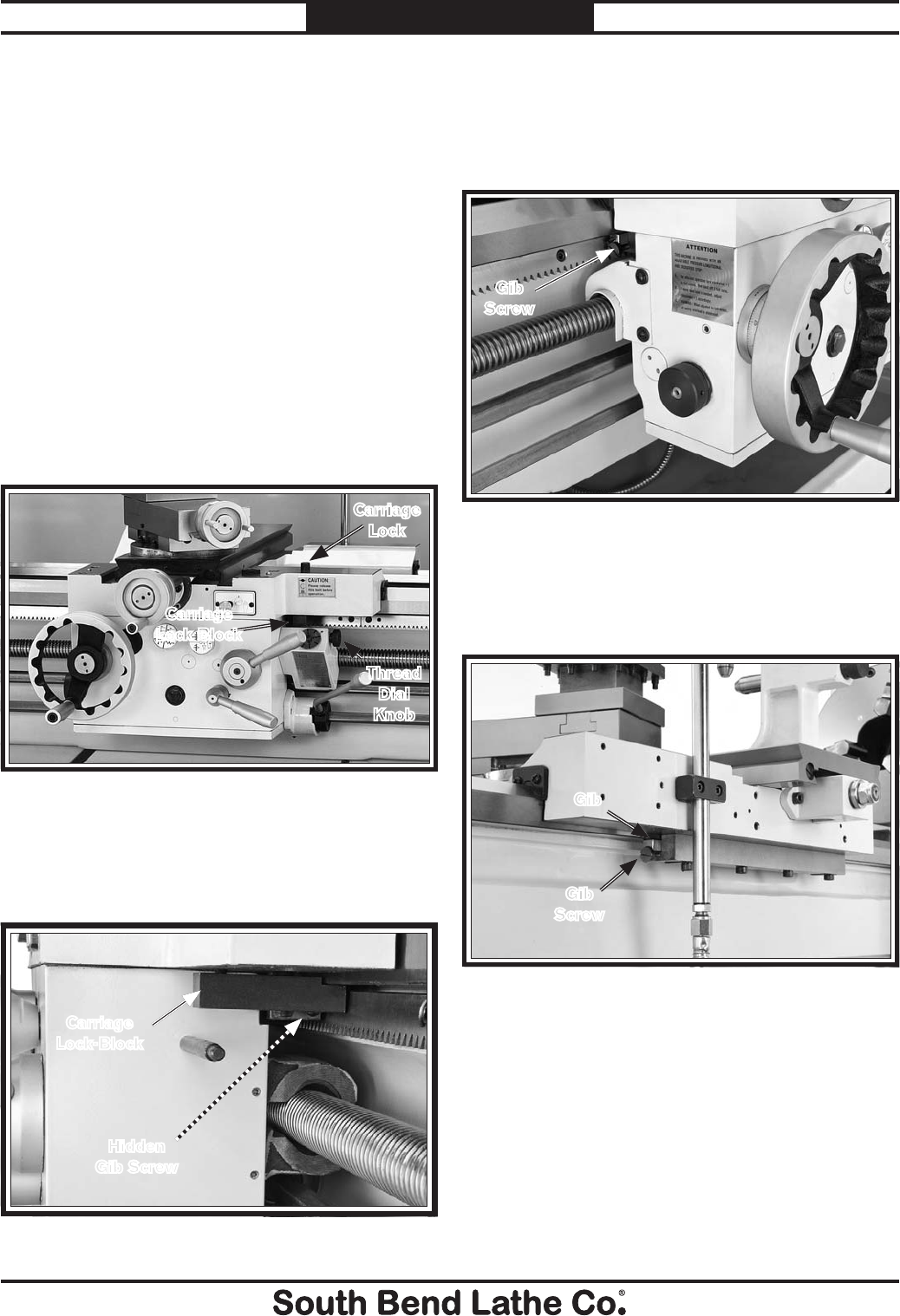
For Machines Mfg. Since 7/09 Model SB1016/SB1036
-79-
SERVICE
Saddle Gibs
The saddle on this lathe is equipped with
opposing gibs that lie parallel with one another
on either side of the saddle. To tighten the saddle
and remove play, the front gib must move toward
the tailstock, and the rear gib must move toward
the headstock.
Tools Needed: Qty
Hex Wrench 6mm .................................................1
Standard Screwdriver #3 ......................................1
To adjust the saddle gibs:
1. DISCONNECT LATHE FROM POWER!
2. Remove the thread dial shown in Figure
137 by removing the lock knob.
Figure 139. Location of carriage lock and half nut for
removal.
Carriage
Lock Block
3. Remove the carriage lock and the carriage
lock-block shown in Figures 137–140.
Carriage
Lock
4. To tighten the front saddle gib (Figure 141)
and move it toward the tailstock, loosen
the tailstock-facing gib screw 1⁄4-turn, and
tighten the headstock-facing gib screw
1⁄4-turn.
Thread
Dial
Knob
Hidden
Gib Screw
Figure 140. Gib screw access.
Figure 141. Front saddle gib screw.
Gib
Screw
5. To tighten the rear saddle gib (Figure 142)
and move it toward the headstock, loosen
the headstock-facing gib screw 1⁄4-turn, and
tighten the tailstock-facing gib screw 1⁄4-turn.
Figure 142. Rear saddle gib and screw.
Gib
Screw
Gib
6. Test the feel of the carriage by turning the
handwheel. Re-adjust the gib screws in the
same manner to tighten or loosen the gibs.
Most machinists find that the ideal gib
adjustment is one where a small amount
of drag or resistance is present yet the
handwheels are still easy to move.
7. Reinstall carriage lock and the thread dial.
Carriage
Lock-Block
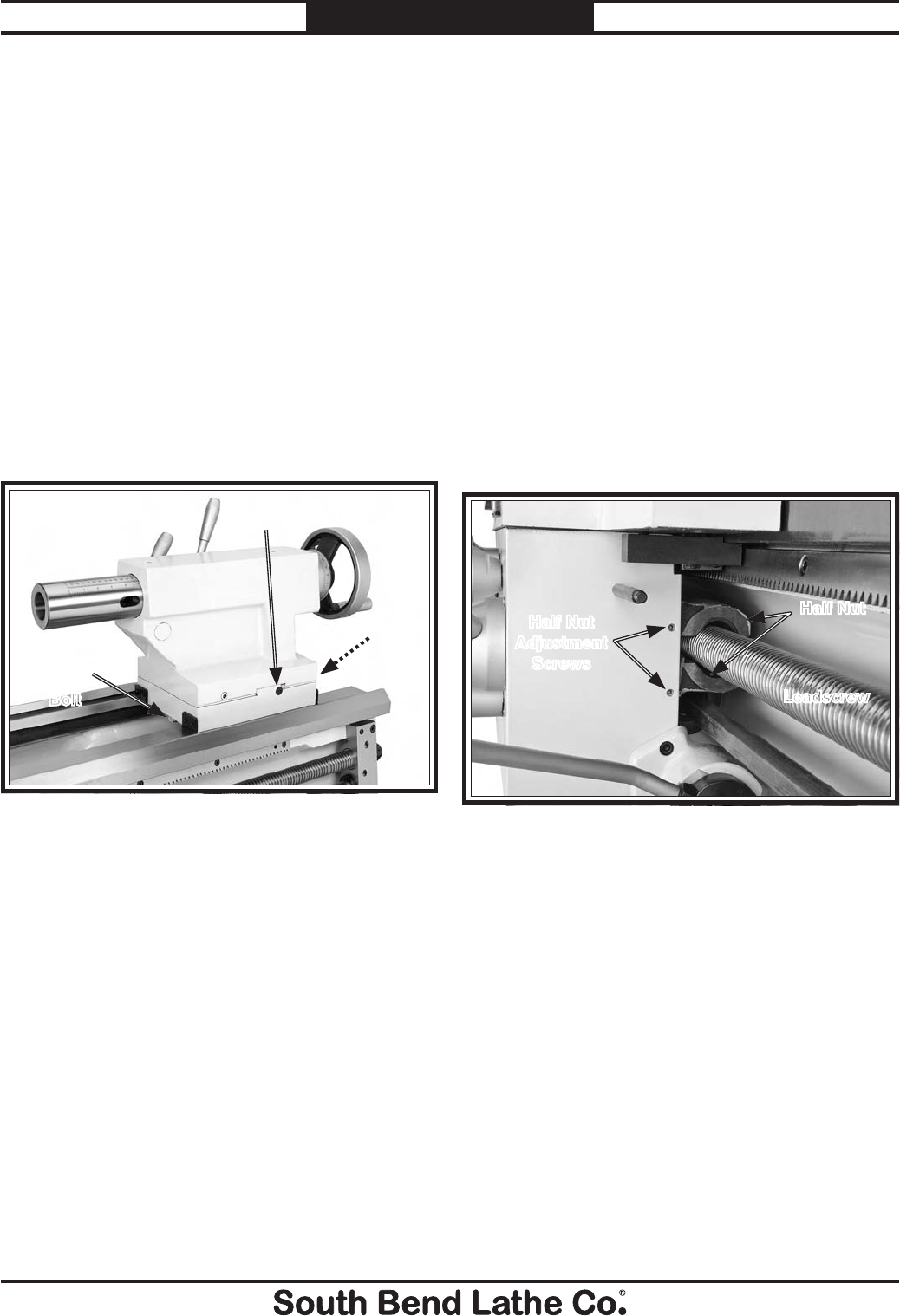
-80-
For Machines Mfg. Since 7/09
Model SB1016/SB1036 SERVICE
Half Nut Adjustment
The half nut mechanism can be tightened if it
becomes loose from wear. The pressure exerted
by the half nut is controlled by a gib. The half
nut gib is adjusted with two set screws.
Tool Needed: Qty
Hex Wrench 3mm .................................................1
To adjust the half nut gib:
1. Disengage the half nut.
2. Remove the thread dial.
3. Turn the half-nut adjustment set
screws, shown in Figure 144, clockwise
approximately an 1⁄8-turn.
Figure 144. Half nut gib adjustment.
Leadscrew
Half Nut
Half Nut
Adjustment
Screws
4. Engage/disengage the half nut several times
and notice how it feels (you may need to
move the carriage handwheel slightly to get
the half nut to close).
The half nut is correctly adjusted when it
has a slight drag while opening and closing.
The movement should not be too stiff or too
sloppy.
5. Repeat Steps 3–4, if necessary, until you are
satisfied with the half nut adjustment. (If
the half nut becomes too stiff, turn the set
screws counterclockwise to loosen it.)
6. Re-install the thread dial.
Tailstock Gib
When the tailstock is offset, it slides along
a dovetailed way that has a gib installed
between the upper and lower tailstock halves.
To maintain alignment and prevent the upper
portion of the tailstock from tilting off-center
when the tailstock is clamped to the ways, the
gib must be fairly snug.
Tools Needed: Qty
Standard Screwdriver #3 ......................................1
Wrench 28mm ....................................................... 1
To adjust the tailstock gib:
1. Loosen the front and rear lock bolts (see
Figure 143), and unlock the tailstock from
the bed.
Front Gib Screw
Figure 143. One of two tailstock gib screws.
Front
Lock
Bolt
Rear
Lock
Bolt
2. To tighten the tailstock gib and move it
toward the splash guard, loosen the splash
guard-facing gib screw 1⁄4-turn, and tighten
the front gib screw shown in Figure 143 1⁄4-
turn.
3. When finished, retighten the lock bolts.
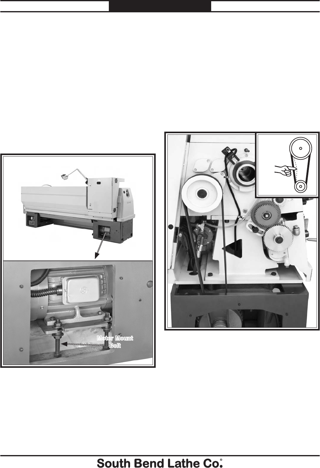
For Machines Mfg. Since 7/09 Model SB1016/SB1036
-81-
SERVICE
V-Belts
V-belts stretch and wear with use, so check them
on a monthly basis to ensure optimal power
transmission. Replace all of the V-belts if any of
them show signs of glazing, fraying, or cracking.
Tools Needed: Qty
Phillips Screwdriver #2 ........................................1
Open End Wrench 24mm......................................1
To adjust the V-belts:
1. DISCONNECT LATHE FROM POWER!
2. Remove the cover shown in Figure 145.
4. Firmly tighten the hex nuts (loosened in the
previous step) against the motor mount plate
to prevent it from moving out of adjustment
during operation, then re-install the motor
cover.
Figure 146. V-belt adjustment.
Pulley
Deflection
Pulley
3. Turn the hex nuts on the motor mount bolts
shown in Figure 146 to move the motor
mount plate up or down and adjust the
V-belt tension. When correctly tensioned,
each belt should have about 3⁄4" deflection
when pressed firmly (see Figure 146).
To ensure that the belts do an equal part
in transmitting power, always replace all of
them at the same time. If one belt is larger
or has more deflection than the others, the
other belts will absorb the additional load
and wear faster.
Figure 145. Location of belt tension adjustment.
Motor Mount
Bolt
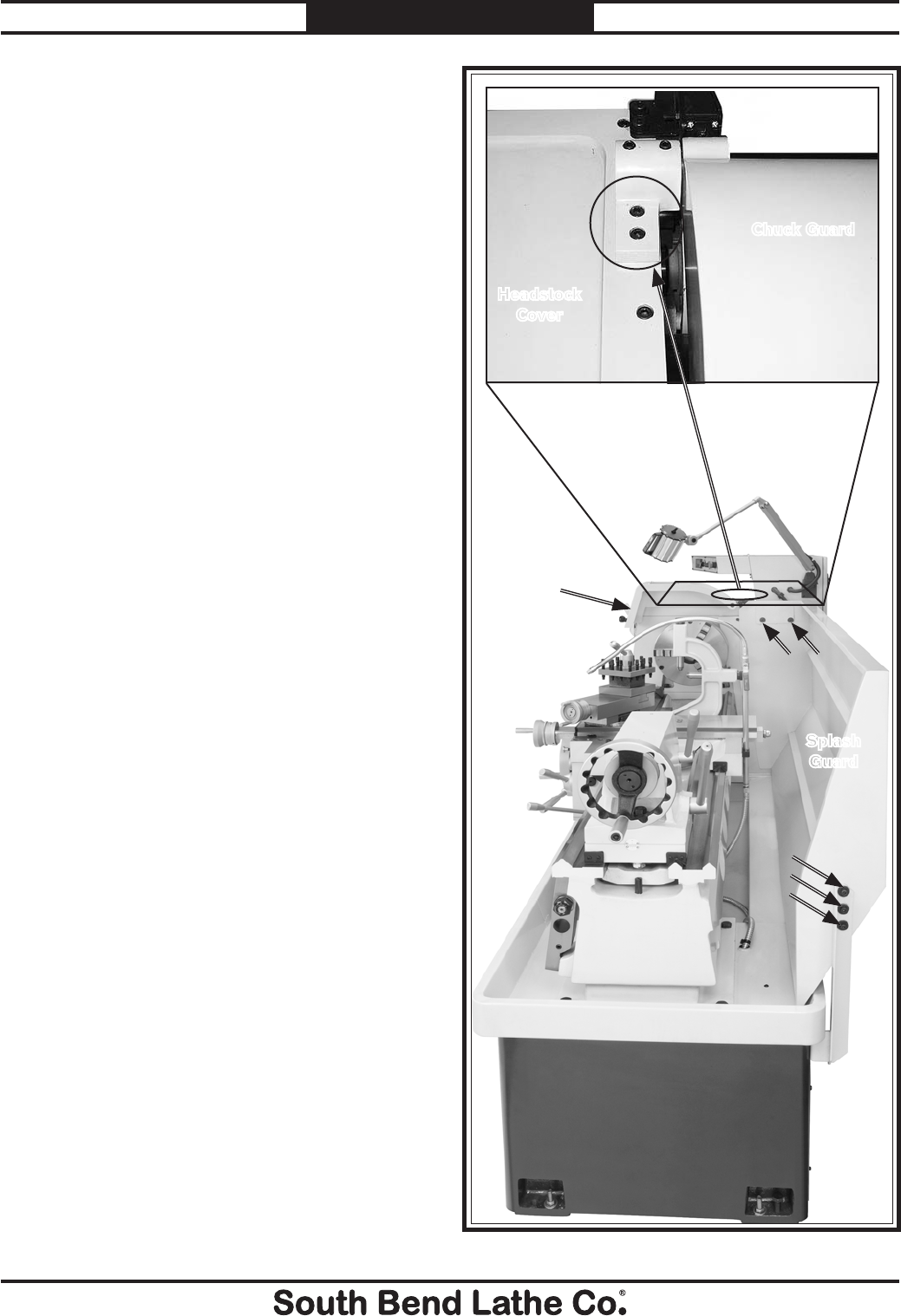
-82-
For Machines Mfg. Since 7/09
Model SB1016/SB1036 SERVICE
Brake Inspection &
Replacement
The linkage geometry on this lathe is non
adjustable. Before replacing the brake shoes,
verify that all fasteners are tight, and all clevis
pins and yokes have minimal wear. As pivot
points wear, the increased slop in the linkage
absorbs the usable stroke that is required for full
brake application. If the brake does not stop the
lathe as fast as it should, before replacing the
brake shoes, verify that the linkage is not worn
and is the cause of the problem.
Tools Needed: Qty
Another Person ....................................................1
Hex Wrench 6mm .................................................1
Hex Wrench 8mm .................................................1
Needle-Nose Pliers ................................................1
Basic Caliper ........................................................ 1
Safety Glasses ...................................................... 1
Respirator Rated for Brake Dust ........................1
To replace the brake shoes:
1. DISCONNECT LATHE FROM POWER!
2. Put on a respirator and eye protection to
protect yourself from hazardous brake dust.
3. With the help of another person, remove the
splash guard, which is attached with the five
capscrews shown in Figure 147.
4. Once the splash guard is removed, remove
the two chuck guard mount cap screws
(Figure 147) and the chuck guard from the
headstock cover.
Figure 147. Tailstock end splash guard fasteners.
Splash
Guard
Chuck Guard
Headstock
Cover
Chuck
Guard
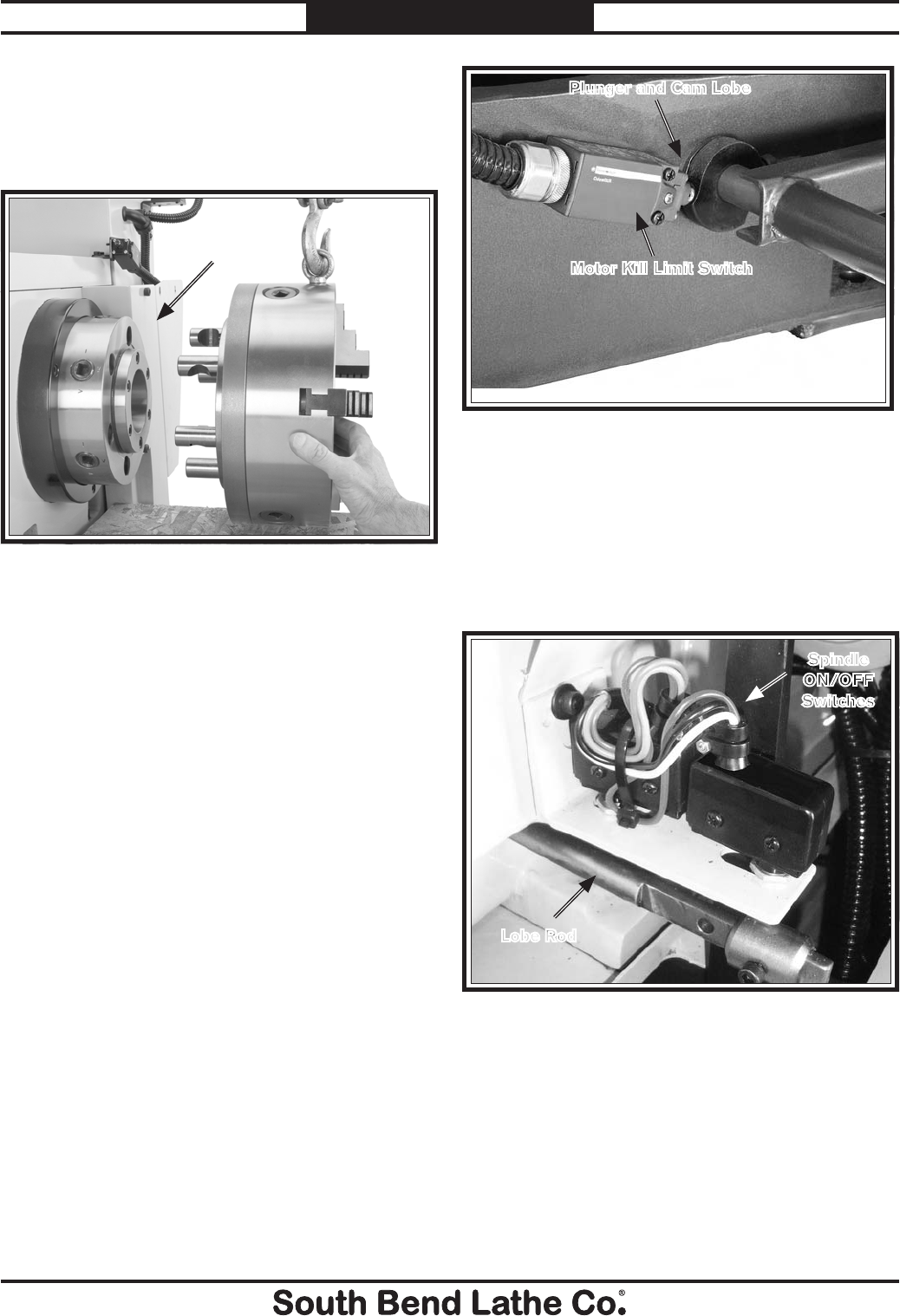
For Machines Mfg. Since 7/09 Model SB1016/SB1036
-83-
SERVICE
Motor Kill Limit Switch
Plunger and Cam Lobe
Figure 149. Brake pedal motor kill switch.
10. While the lathe is disconnected from power
have your assistant move the spindle ON/
OFF lever up to forward, neutral, and
reverse, while you verify the lobe rod shown
in Figure 150 operates the switches without
any loose switch mounts, cap screws, or
interference.
Figure 150. Lobe rod and spindle ON/OFF switch.
Lobe Rod
Spindle
ON/OFF
Switches
5. Place sheet of wood on the ways to protect
them when the chuck is removed.
6. Using the appropriate lifting apparatus,
remove the chuck as shown in Figure 148.
Figure 148. Removing the 3-jaw chuck from a spindle
nose.
Brake
Linkage
Cover
7. Remove the cap screws that fasten the brake
linkage cover shown in Figure 149 to the
headstock.
8. Remove the brake linkage cover.
9. Have your assistant step on the brake pedal
while you verify that the cam lobe shown in
Figure 149 makes the kill switch plunger
click when pushed.
— If the switch does not click, loosen the
switch mounting screws, push the pedal
all the way down, and move the switch
closer to the lobe until it clicks. Secure the
switch in place at this location.
— With the foot pedal released, the switch
plunger should be approximately 3mm
from the lobe.
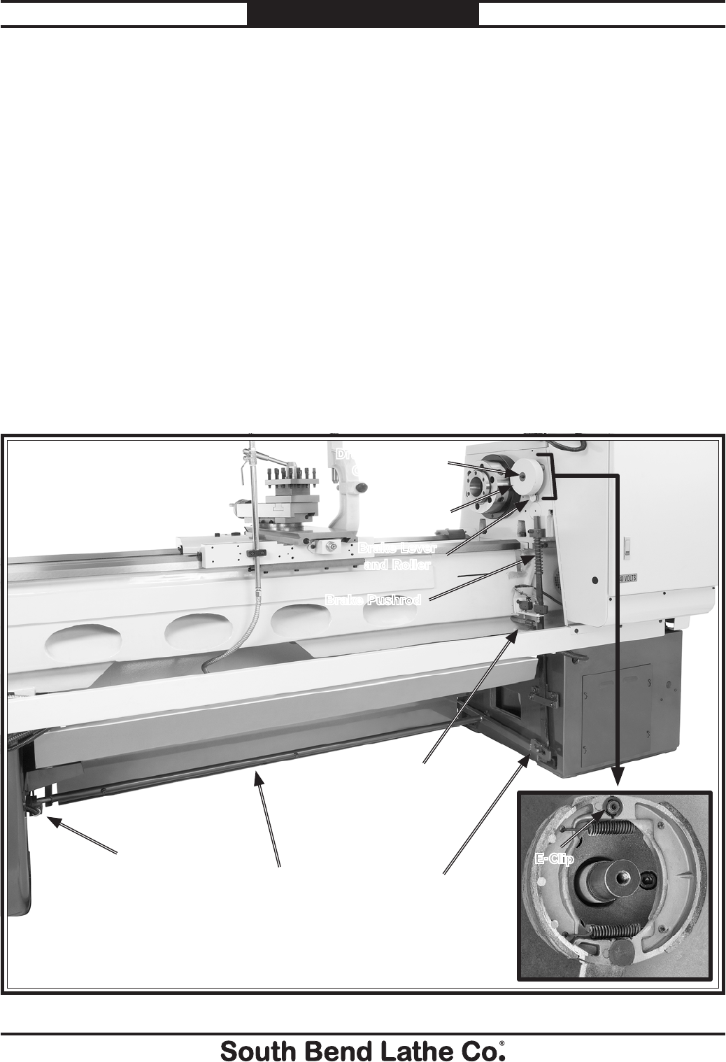
-84-
For Machines Mfg. Since 7/09
Model SB1016/SB1036 SERVICE
11. Have your assistant press on the brake pedal
a few times while you watch all of the brake
linkage for any loose fasteners or worn pivot
points and pins. Tighten or replace parts as
required.
12. Have your assistant step on and hold the
brake pedal to lock the drum in place.
13. Remove the drum retaining cap screw shown
in Figure 151.
14. Remove the brake drum, E-Clip, and shoes
shown in Figure 151, and the brake shoes.
15. Use mineral spirits to clean the drum.
Then inspect it. If the drum is bell-mouthd,
cracked, or shows deep grooves, replace it.
For minor scoring, the drum can be dressed
with sandpaper or turned on a lathe.
Figure 151. Complete brake system.
Brake
Lever and
Roller
Motor Kill
Switch
Brake Pushrod
E-Clip
Brake Drum
and Shoes
Brake Lever
and Roller
16. Clean the brake shoes with hot soapy water
and inspect. When evaluating the brake
shoes, replace the shoes as a set if the lining
thickness discussed below is 3⁄16" or less, or
if the linings are loose on the rivets, or if the
bonded linings are separating from the shoe.
— If riveted linings are present, measure
the lining thickness by determining how
much lining is left before the tops of the
rivet heads will begin to score the drum.
— If bonded linings are present, view the
brake shoe from the side, and measure
the thickness of the remaining lining
before the metal brake shoe begins to
score the drum.
17. Re-install the guards and covers, and test for
brake operation.
Drum Retaining
Cap Screw
Foot Pedal
Support Rod
Lobe Rod
and
Spindle ON/OFF
Switches
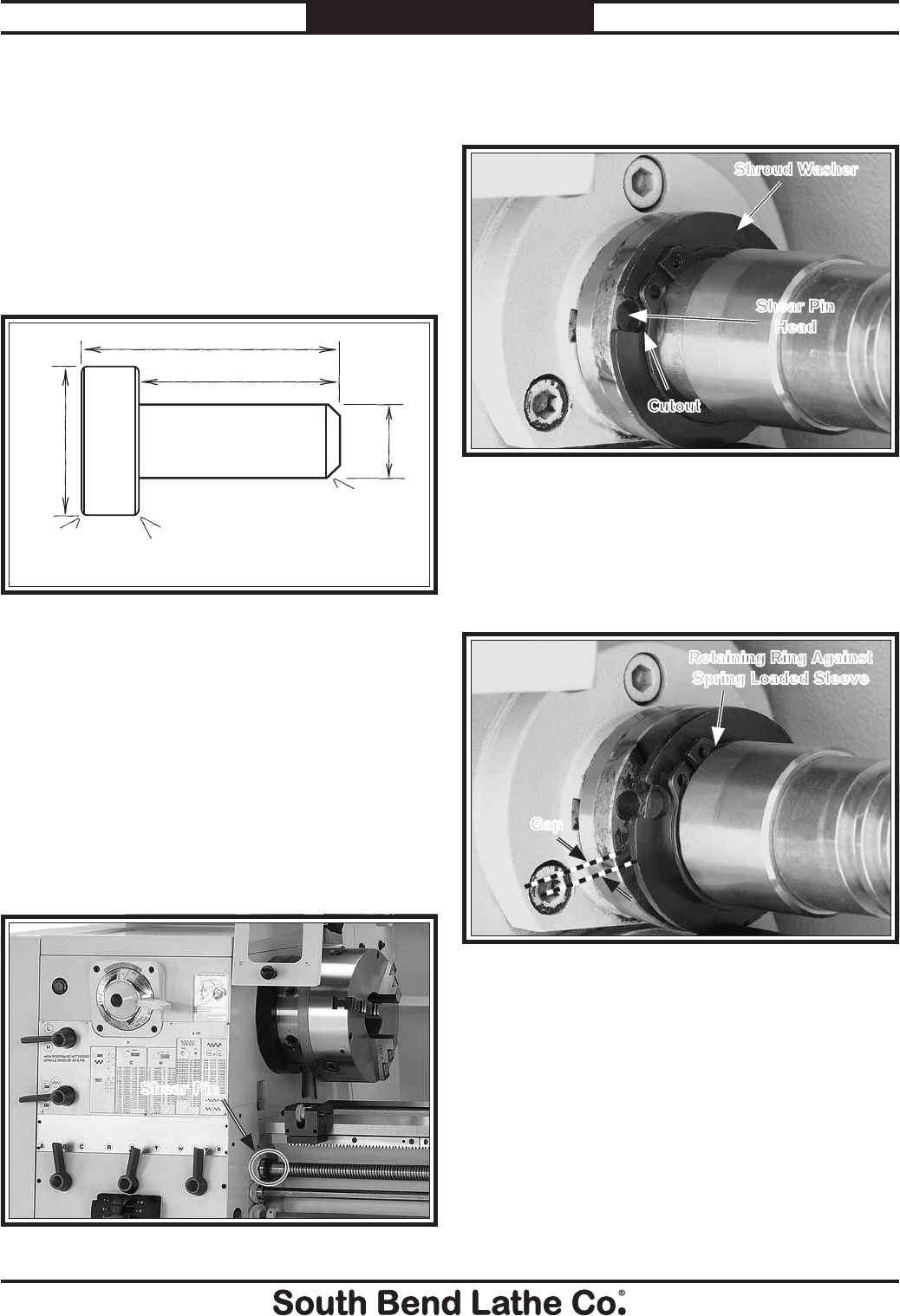
For Machines Mfg. Since 7/09 Model SB1016/SB1036
-85-
SERVICE
Leadscrew Shear Pin
Replacement
3. Rotate the shroud washer so the cutout in
the washer aligns with the shear pin head,
as shown in Figure 154.
4. Put on safety glasses.
5. Slide the retaining ring away from the
shroud washer so it rests against the spring-
loaded sleeve as shown in Figure 155.
Figure 154. Shroud washer/pin alignment.
Shear Pin
Head
Shroud Washer
Cutout
10.54mm
8.75mm
5.8mm
0.5mm
0.2mm0.2mm
3.74mm
NOTE: Shear Pin Material = S45C (SAE 1045)
Figure 152. Shear pin specifications.
Tools Needed: Qty
Phillips Screwdriver #2 ........................................1
External Retaining Ring Pliers 90° #2 ................1
Magnet ...................................................................1
Safety Glasses ....................................................... 1
To replace the shear pin:
1. DISCONNECT LATHE FROM POWER!
2. Clean shear pin area shown in Figure 153
with mineral spirits, then dry with a rag.
Figure 153. Shear pin location.
Shear Pin
If the shear pin has broken, do not improvise
by inserting a roll pin, cotter pin, steel dowel,
or nail. Should the pin need to shear again,
catastrophic gearbox damage may result. Order
extras or make your own set of shear pins using
the specifications shown in Figure 152.
Figure 155. Shear pin access.
Retaining Ring Against
Spring Loaded Sleeve
Gap
6. Slide the shroud washer against the
retaining ring, as shown in Figure 155.
There must be enough of a gap to remove the
shear pin.
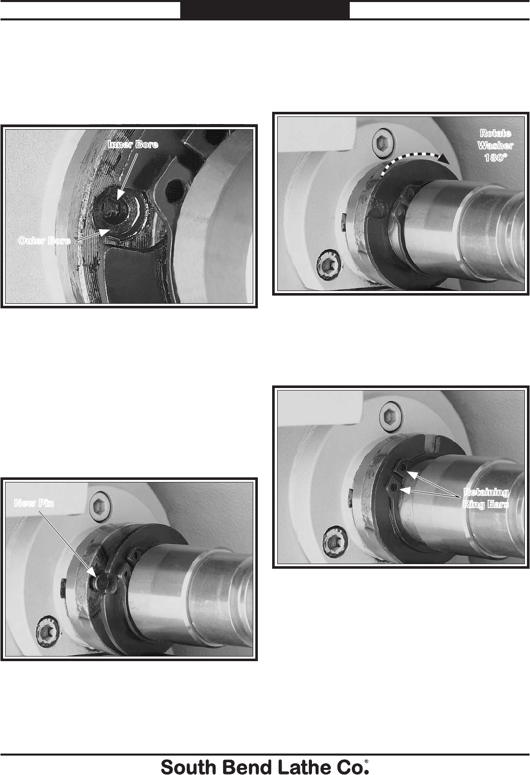
-86-
For Machines Mfg. Since 7/09
Model SB1016/SB1036 SERVICE
10. With the pin completely seated in the bore
and the head flush with the leadscrew
shoulder, slide the shroud washer against
the shoulder, and rotate it 180° (see Figure
158) to cover the shear pin.
Figure 157. New shear pin installed in bore.
New Pin
8. Blow out the shear pin hole with compressed
air, and put a drop of oil in the hole.
9. Insert the new shear pin into the bore, as
shown in Figure 157. If the pin does not
freely slide into the bore, DO NOT hammer
on the pin or you will mushroom the shear
pin head, preventing installation. Instead,
file a slight chamfer on the end of the pin to
make it easier to align and insert.
7. Use the magnet to remove the shear pin
head, then rotate the lathe spindle by hand
to line up the inner and outer bores, as
shown in Figure 156. Next, use the magnet
to remove the other half of the broken shear
pin when it becomes visible.
Figure 156. Aligned shear pin bores.
Outer Bore
Inner Bore
11. Slide the retaining ring against the shroud
washer, so the retaining-ring ears are offset
from the hole in the shroud washer, as
shown in Figure 159.
Figure 158. Rotating washer to cover shear pin.
Rotate
Washer
180°
Figure 159. Offset positioning of retaining ring ears
and hole in shroud washer.
Retaining
Ring Ears
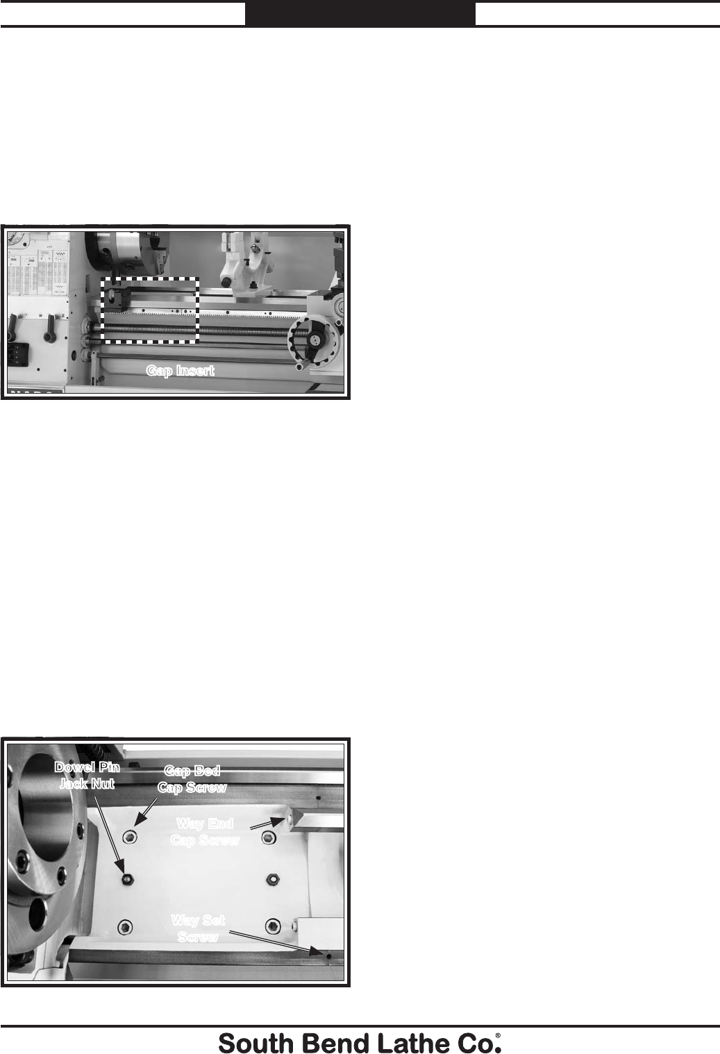
For Machines Mfg. Since 7/09 Model SB1016/SB1036
-87-
SERVICE
The gap insert was installed, then ground flush
with the bed at the factory to ensure precise fit
and alignment. Therefore, if removed, it may
be difficult to re-install with the same degree
of alignment and mating when installed at the
factory.
Gap Removal &
Installation
2. Remove the two way-end cap screws, and
way set screws shown in Figure 161.
3. Tighten the two dowel pin jack nuts (Figure
161) until the pins are pulled free from the
gap insert.
4. Tap the outside of the gap insert with a dead
blow hammer to loosen, and remove it.
To re-install the gap insert:
1. Use mineral spirits and a clean lint-free rag
to clean the mating surfaces of the gap, bed,
and ways. If necessary, stone the mating
surfaces to remove scratches, dings, or burrs.
2. Wipe a thin layer of light machine oil on the
mating surfaces.
3. Place the gap insert into the bed and use a
block of wood or dead-blow hammer to align
it with the lathe bed.
4. Back off the dowel pin jack nuts, and tap the
dowel pins back into their respective holes
until seated. This will further help align the
gap insert and bed mating surfaces.
5. Install all fasteners (except the way set
screws) and lightly snug them in place.
6. Mount a base-mounted dial indicator to the
top of the saddle to indicate alignment. First
test the peak of the two prisms the saddle
rides on, then test the flanks of the prisms.
Jack the insert up or down by tightening or
loosening the gap bed cap screws.
7. Alternately tighten the fasteners and tap the
side of the gap insert into alignment.
8. Inspect the gap position 24 hours later to
make sure the gap is still aligned. Adjust
if necessary, then install the two way set
screws.
Tools Needed: Qty
Hex Wrenches 6, 14mm ...............................1 Each
Wrench 19mm ....................................................... 1
Box Cutter or Razor Blade....................................1
To remove the gap insert:
1. Remove the four gap bed cap screws, shown
in Figure 161, that secure the gap insert to
the bed.
Figure 161. Fasteners holding gap in place.
Gap Bed
Cap Screw
Way End
Cap Screw
Way Set
Screw
Dowel Pin
Jack Nut
Figure 160. Gap insert that can be removed from bed.
Gap Insert
The gap insert (Figure 160), is a portion of the
lathe bed directly under the spindle that can be
removed to create additional space for turning
large diameter parts.

TROUBLESHOOTING
-88-
For Machines Mfg. Since 7/09
Model SB1016/SB1036 WARRANTY
If you need replacement parts, or if you are unsure how to do any of the solutions given here, feel free
to call us at (360) 734-1540.
Symptom Possible Cause Possible Solution
Machine does not
start or a circuit
breaker trips.
1. (First time operation only) Lathe
may be wired with the incorrect
phase polarity.
1. Correct phase polarity (refer to Page 16 for details).
2. Emergency stop push-button is
engaged or at fault.
2. Rotate button clockwise until it pops out to reset it
for operation; replace if not working properly.
3. Spindle ON/OFF switch is at fault. 3. Move the spindle ON/OFF lever to ON; replace bad
switch.
4. Power supply is switched OFF at
master power switch or breaker.
4. Make sure master power switch and circuit breaker
are turned ON.
5. Wall fuse/circuit breaker is blown/
tripped; short in electrical system;
start-up load too high for circuit.
5. Verify circuit is rated for machine amp load;
troubleshoot and repair cause of overload; replace
weak breaker; find/repair electrical short.
6. Fuse has blown in machine
electrical box due to thermal
overload.
6. Replace fuse; determine if overload is due to heavy
operation; ensure power source has high enough
voltage and cord is correctly sized.
7. One or more kill switches are
engaged.
7. Verify electrical box door, chuck guard, gear cover,
spindle, and brake switches are not engaged.
Headstock oil pump is not pumping, or is wired
with the incorrect phase polarity. Correct pump
phase polarity, refer to Page 16.
8. Motor connection wired incorrectly. 8. Correct motor wiring connections.
9. Oil pump motor operating, but oil is
not seen pumping past sight glass.
9. Prime pump, fill headstock oil tank to full, or
replace oil pump.
10. Limit/kill switch at fault. 10. Test all limit/kill switches and replace as necessary.
11. Contactor not getting energized/has
burnt contacts.
11. Test for power on all legs and contactor operation.
Replace unit if faulty.
12. Wiring is open/has high resistance. 12. Check for broken wires or disconnected/corroded
connections, and repair/replace as necessary.
13. Motor is at fault. 13. Test/repair/replace.
14. Frequency drive unit is at fault. 14. Contact frequency drive manufacturer for list of
authorized service providers in your area.
Loud, repetitious
noise coming from
lathe at or near the
motor.
1. Pulley set screws or keys are
missing or loose.
1. Inspect keys and set screws. Replace or tighten if
necessary.
2. Motor fan is hitting the cover. 2.Tighten fan, shim cover, or replace items.
Motor overheats. 1. Motor overloaded. 1. Reduce load on motor.
2. Frequency drive unit is at fault. 2.Contact frequency drive manufacturer for list of
authorized service providers in your area.
Motor is loud when
cutting, or bogs
down under load.
1. Excessive depth of cut or feed rate. 1. Decrease depth of cut or feed rate.
2. Spindle speed or feed rate wrong for
cutting operation.
2. Refer to the feeds and speeds charts in
Machinery's Handbook or a speeds and feeds
calculator on the internet.
3. Cutting tool is dull. 3. Sharpen or replace the cutting tool.

For Machines Mfg. Since 7/09 Model SB1016/SB1036
-89-
WARRANTY
Symptom Possible Cause Possible Solution
Entire machine
vibrates upon
startup and while
running.
1. Workpiece is unbalanced. 1. Re-install workpiece as centered with the spindle
bore as possible.
2. Loose or damaged belt(s). 2. Tighten/replace the belt as necessary (Page 81).
3. V-belt pulleys are not properly
aligned.
3. Align the V-belt pulleys.
4. Worn or broken gear present. 4. Inspect gears and replace if necessary.
5. Chuck or faceplate has become
unbalanced.
5. Rebalance chuck or faceplate; contact a local
machine shop for help.
6. Gears not aligned in headstock or
no backlash.
6. Adjust gears and establish the correct amount of
backlash.
7. Broken gear or bad bearing. 7. Replace broken gear or bearing.
8. Workpiece is hitting stationary
object.
8. Stop lathe immediately and correct interference
problem.
9. Spindle bearings at fault. 9. Rest spindle bearing preload or replace worn
spindle bearings.
Bad surface finish. 1. Wrong spindle speed or feed rate. 1. Adjust for appropriate spindle speed and feed rate.
2. Dull tooling or poor tool selection. 2. Sharpen tooling or select a better tool for the
intended operation.
3. Tool height not at centerline. 3. Adjust tool height to centerline.
4. Too much play in gibs. 4. Tighten gibs (Page 78).
Tapered tool
difficult to remove
from tailstock quill.
1. Quill is not retracted all the way
back into the tailstock.
1. Turn the quill handwheel until it forces taper out of
quill.
2. Contaminants not removed from
taper before inserting into quill.
2. Clean the taper and bore and re-install tapered tool.
Cross slide,
compound, or
carriage feed has
sloppy operation.
1. Gibs are out of adjustment. 1. Tighten gib screw(s) (Page 78).
2. Handwheel is loose or backlash is
high.
2. Tighten handwheel fasteners, adjust handwheel
backlash to a minimum.
3. Lead screw mechanism worn or out
of adjustment.
3. Adjust leadscrew to remove endplay (Page 78).
Cross slide,
compound, or
carriage feed
handwheel is hard
to move.
1. Dovetail slides loaded up with
shavings, dust, or grime.
1. Remove gibs, clean ways/dovetails, lubricate, and
readjust gibs.
2. Gib screws are too tight. 2. Loosen gib screw(s) slightly, and lubricate bedways.
3. Backlash setting too tight (cross
slide only).
3. Slightly loosen backlash setting (Page 78).
4. Bedways are dry. 4. Lubricate bedways and handles.
Cutting tool
or machine
components vibrate
excessively during
cutting.
1. Tool holder not tight enough. 1. Check for debris, clean, and retighten.
2. Cutting tool sticks too far out of tool
holder; lack of support.
2. Re-install cutting tool so no more than 1⁄3 of the total
length is sticking out of tool holder.
3. Gibs are out of adjustment. 3. Tighten gib screws at affected component.
4. Dull cutting tool. 4. Replace or resharpen cutting tool.
5. Incorrect spindle speed or feed rate. 5. Use the recommended spindle speed.

-90-
For Machines Mfg. Since 7/09
Model SB1016/SB1036 WARRANTY
Gear change levers
will not shift into
position.
1. Gears not aligned inside headstock. 1. Rotate spindle by hand with light pressure on the
lever until gear falls into place.
Carriage will not
feed, or is hard to
move.
1. Gears are not all engaged. 1. Adjust gear levers.
2. Loose screw on the feed handle. 2. Tighten.
3. Carriage lock is tightened down. 3. Check to make sure the Carriage Lock is fully
released.
4. Chips have loaded up on bedways. 4. Frequently clean away chips that load up during
turning operations.
5. Bedways are dry and in need of
lubrication.
5. Lubricate bedways and handles.
6. Micrometer stop is interfering. 6. Check micrometer stop position, and adjust it as
necessary (Page 51).
7. Gibs are too tight. 7. Loosen gib screw(s) slightly (Page 78).
8. Gears or shear pin broken. 8. Replace gears or shear pin (Page 85).
Headstock oil
does not flow or
circulate properly.
1. (For first time operation only) The
oil pump phase polarity is wired
incorrectly.
1. Correct oil pump phase polarity (refer to Page 16
for details).
2. Emergency stop push-button is
engaged or at fault.
2. Rotate button clockwise until it pops out to reset it
for operation; replace if not working properly.
3. Power supply is switched OFF at
master power switch or breaker.
3. Make sure master power switch and circuit breaker
are turned ON.
4. Insufficient oil level in headstock
oil tank or incorrect oil used in
headstock oil tank.
4. Add oil to the headstock oil tank (refer to
Headstock "Checking & Adding Oil" on Page 66
for details). Make sure to use the correct type of oil.
5. Suction screen clogged. 5. Clean suction screen (Page 69).
6. Pinched/damaged oil line. 6. Trace oil lines to inspect and replace pinched/
damaged line.
7. Suction side of pump drawing air. 7. Locate leak and reseal/replace affected components.
8. Leak in distribution manifold
located inside headstock.
8. Locate leak and reseal/replace affected components.
9. Pump motor at fault. 9. Replace/repair pump motor.
Symptom Possible Cause Possible Solution
Workpiece is
tapered.
1. Headstock and tailstock are not
properly aligned with each other.
1. Realign the tailstock to the headstock spindle bore
centerline (Page 44).
Chuck jaws will
not move or do not
move easily.
1. Chips lodged in the jaws or scroll
plate.
1. Remove jaws, clean and lubricate scroll plate, then
replace jaws.

For Machines Mfg. Since 7/09 Model SB1016/SB1036
-91-
ELECTRICAL
ELECTRICAL
Electrical Safety Instructions
These pages are accurate at the time of printing. In the constant effort to improve, however, we may
make changes to the electrical systems of future machines. Study this section carefully. If you see
differences between your machine and what is shown in this section, call Technical Support at (360)
734-1540 for assistance BEFORE making any changes to the wiring on your machine.
1. Shock Hazard: It is extremely dangerous to
perform electrical or wiring tasks while the
machine is connected to the power source.
Touching electrified parts will result in
personal injury including but not limited to
severe burns, electrocution, or death. For
your own safety, disconnect machine from
the power source before servicing electrical
components or performing any wiring tasks!
2. Wire Connections: All connections must be
tight to prevent wires from loosening during
machine operation. Double-check all wires
disconnected or connected during any wiring
task to ensure tight connections.
3. Modifications: Using aftermarket parts or
modifying the wiring beyond what is shown
in the diagram may lead to unpredictable
results, including serious injury or fire.
4. Motor Wiring: The motor wiring shown
in these diagrams is current at the time of
printing, but it may not match your machine.
Always use the wiring diagram inside the
5. Circuit Requirements: Connecting the
machine to an improperly sized circuit will
greatly increase the risk of fire. To minimize
this risk, only connect the machine to a
power circuit that meets the minimum
requirements given in this manual.
6. Capacitors/Inverters: Some capacitors and
power inverters store an electrical charge for
up to 10 minutes after being disconnected
from the power source. To reduce the risk of
being shocked, wait at least this long before
working on capacitors.
7. Wire/Component Damage: Damaged wires
or components increase the risk of serious
personal injury, fire, or machine damage. If
you notice that any wires or components are
damaged while performing a wiring task,
replace those wires or components before
completing the task.
8. Experiencing Difficulties: If you are
experiencing difficulties understanding the
information included in this section, contact
The photos and diagrams included in this section are best viewed in color. You can
see them in color at www.southbendlathe.com.
BLACK WHITE
GREEN
RED
BLUE
BROWN GRAY ORANGE YELLOW
YELLOW
GREEN
PURPLE
PINK
LIGHT
BLUE
BLUE
WHITE
TUR-
QUIOSE
NOTICE:
WIRING DIAGRAM COLOR KEY
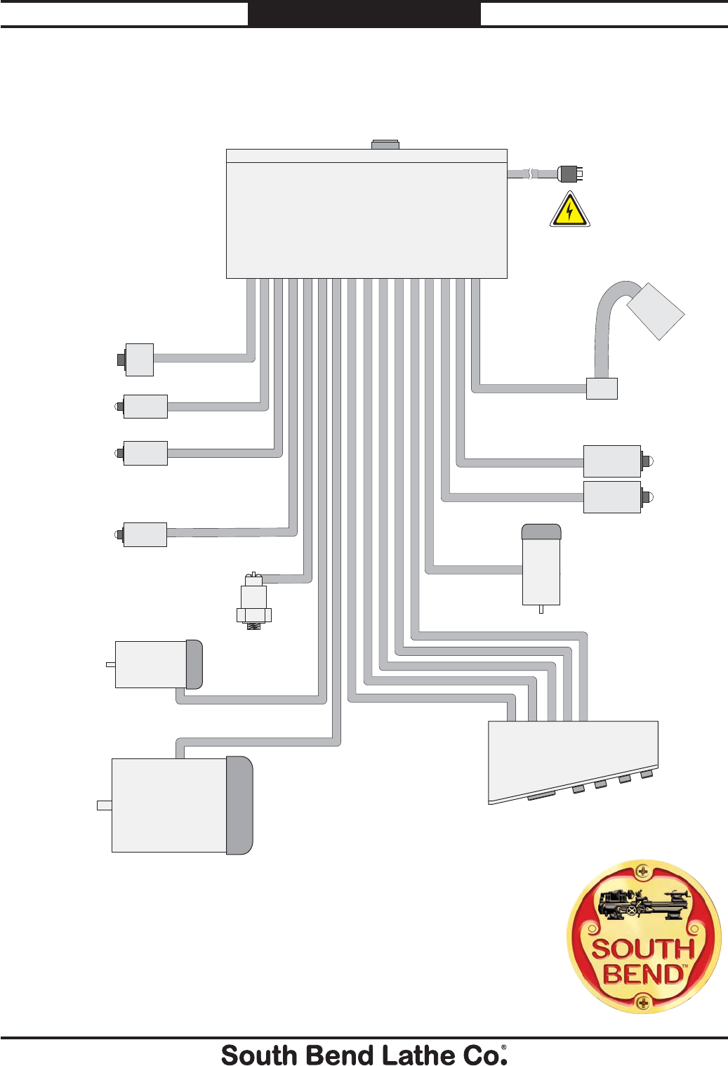
-92-
For Machines Mfg. Since 7/09
Model SB1016/SB1036 ELECTRICAL
Wiring Overview
Spindle Motor,
Page 97.
Cutting Fluid
Pump Motor,
Page 99.
Oil Pump
Motor,
Page 98.
Oil Pressure
Switch,
Page 98.
End Gear Cover
Safety Switch,
Page 102.
Brake Limit Safety
Switch, Page 102. Spindle
ON/OFF
Switch,
Page
101.
Spindle RPM
Sensor, Page 102.
Chuck Guard Safety
Switch, Page 102.
Electrical
Box, Pages 94–95.
Control Panel,
Page 100.
Work Lamp,
Page 102.
Power Supply
Connection
Page 101.
wiring overview
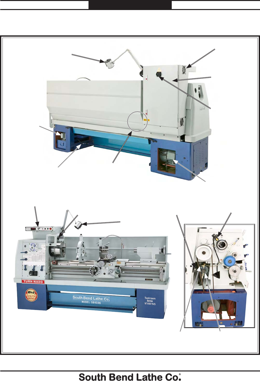
For Machines Mfg. Since 7/09 Model SB1016/SB1036
-93-
ELECTRICAL
Figure 162. Component location index.
Cutting Fluid
Pump Motor,
Page 99.
Oil Pump
Motor,
Page 98.
Oil Pressure
Sensor,
Page 98.
Brake Pedal Safety
Switch, Page 102.
Chuck Guard Limit
Switch, Page 102.
Electrical
Box, Pages
94–95.
Cooling Fan,
Page 94.
Master Power
Switch, Page 94.
Control Panel,
Page 100.
Work Lamp,
Page 102.
Work Lamp,
Page 102.
SB1016/36 Component Location Index visual index
End Gear Cover
Safety Switch,
Page 102.
Spindle RPM
Sensor, Page
102.
Spindle
Switch (Behind
Splash Guard),
Page 101. Spindle Motor,
Page 97.
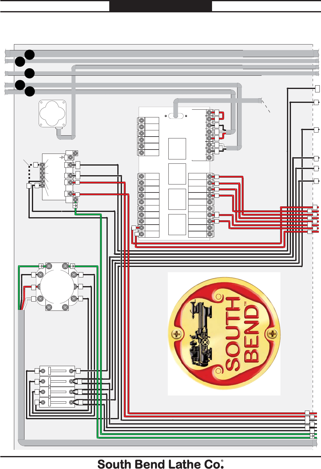
-94-
For Machines Mfg. Since 7/09
Model SB1016/SB1036 ELECTRICAL
X
X
X
X
X
0 24 0 220
0 220 380 400 415 440
TRANSFORMER
(For SB1036 440V Only)
X
X
X
X
X
X
X
X
X
X
X
X
X
X
X
X
X
X
X
X
X
X
X
X
X
X
X
X
X
X
X
L1 L4L3L2
X
X
X
CIRCUIT BOARD
KR1
24V
0V
KR4 COM
KR4 NO
KR4 NC
0V
KR4
KR3
KR2
NO
24V COM
BRAKE
NC
NO
NO
SROTATION
COM
CHUCK
NC
COM
JOG
CSS
3
2
1S2
COM
S1
S5
S4
S3
COOLING
FAN
L13
L13 L11
L1
L1
L1
L3
L3
L3
L2
L2
L2
L1
L1
L1
L3
L2L1 2
2
A1
11
11
9 6 7 85
A1 9
6
7
8
5
0
0
64631413122019
1
2
3
5
1
2
3
4
5
6
1
2
6
4
MASTER
POWER SWITCH
L3 L3
L2L1
3
3
L11
L3 L3
L2
L1 L1
L1
D
EC
B
A
box1
SB1016/36 Electrical Box Wiring
To Varispeed Unit, Page 95.
To Page 95. To Page 95. To Page 95.
To Control Panel, Page 100.
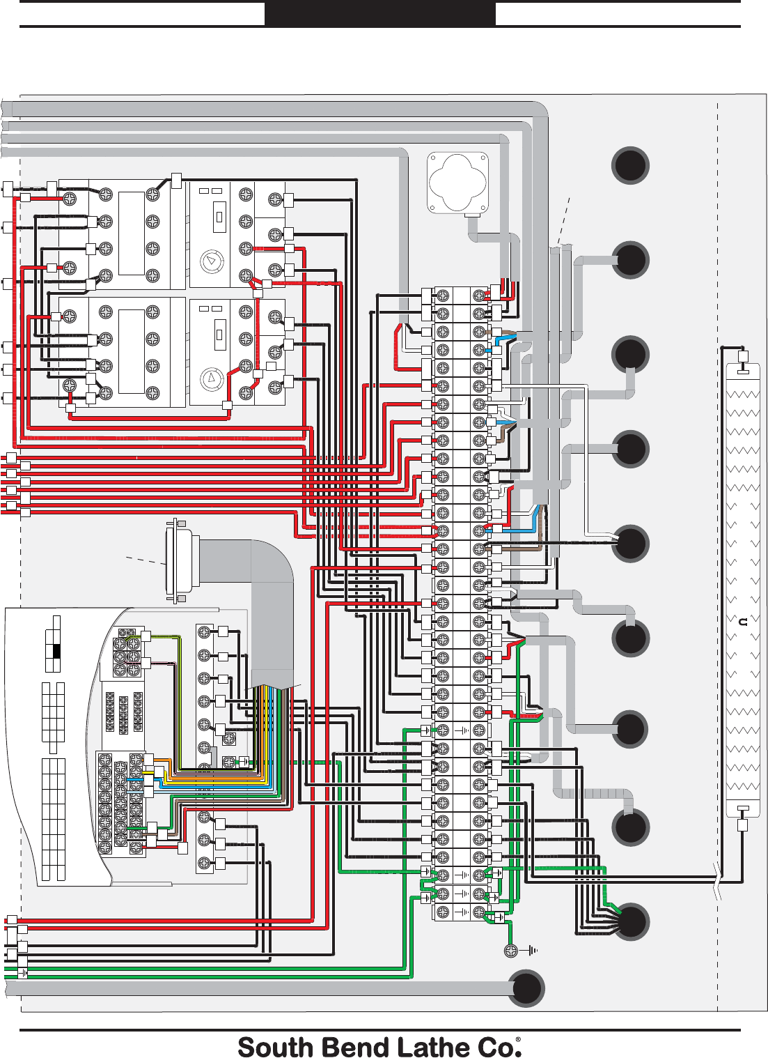
For Machines Mfg. Since 7/09 Model SB1016/SB1036
-95-
ELECTRICAL
box2
AMP
CONTACTOR
Allen Bradley
C09400
AMP
THERMAL
RELAY
THERMAL
RELAY
L11
L11
L3
L3
L3
L3
L2L2
L2
L1L1
L1
L1
L1
2
2
2
2
4
CONTACTOR
Allen Bradley
C09400
1357L1 L2 L3 L4 1 3 5 7L1 L2 L3 L4
2468T1
2T1
T2
4T2
T3
6 T3 2 T1 4 T2 6 T3
T4 2 4 6 8T1 T2 T3 T4
95 96 NONC 97 98 95 96 NONC 97 98
L13
L11
L
K
COM
11
9
8
7
6
A1
5
4
3
2
2
1
0
W2
V2
U2
W1
V1
U1
L13
L11
W
V
U
L11 L13 U1 V1 W1 U2 V2 W2
U V
A1 9
6
7
8
5
3 3
W
U V W
0 3 4 5 6 7 8 9 11 L11 L13A1
L13
L3
L2
L1
211
0
79 8? 35 3? B# B$ B5 E5
E5 3# 3$ 3% H 35 H
E# E$ E% E& E' E( E) E*
?B B% 5% B& 5&
DB D D E E
E+ E#"E## E#$ #9
?3 ?4 ?5
?# ?$ 7
9
G7
Varispeed
N6H@6L6
K6G>67A:HE::9JC>I
G:;:GIDN6H@6L6DLC:GHB6CJ6A
Ground
11
10
U1 V1 W1 U2 V2 W2 0 1 2 2 3456789K LCOM L11 L13
A1
17
15
16
L1 L2 L3 B1 B2
B1 B2
13 12 14
23
18
K LCOM
U1 V1 W1 U2 V2 W2
2
L11
B1
B2
U V W 11
THERMAL RESISTOR
1600W/35
COOLING
FAN
2
2
2
B1 B2
B1 B2
R/L1 S/L2 T/L3 1 2 B1 B2 U/T1 V/T2 W/T3
L11 L13
2 2
SB1016/36 Electrical Box Wiring
To Cutting
Fluid Pump
Motor,
Page 99.
To Oil Pump
Motor,
Page 98.
To Oil
Pressure
Sensor,
Page 98.
To Brake Pedal
Safety Switch,
Page 102.
To End gear
Safety Switch,
Page 102.
To Spindle
RPM Sensor,
Page 102.
To Work
Lamp,
Page 102.
To Chuck
Guard Safety
Switch, Page
102.
To Spindle
Switch,
Page 101.
To Spindle
Motor,
Page 97.
To Incoming
Power,
Page 101.
To Circuit
Board,
Page 94.
To Page 94. To Page 94.To Page 94.
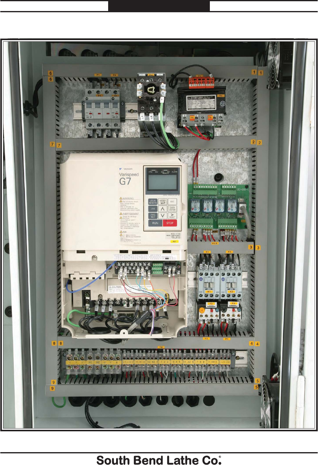
-96-
For Machines Mfg. Since 7/09
Model SB1016/SB1036 ELECTRICAL
Fig. 163. Electrical box.
SB1016/36 Electrical Box box photo
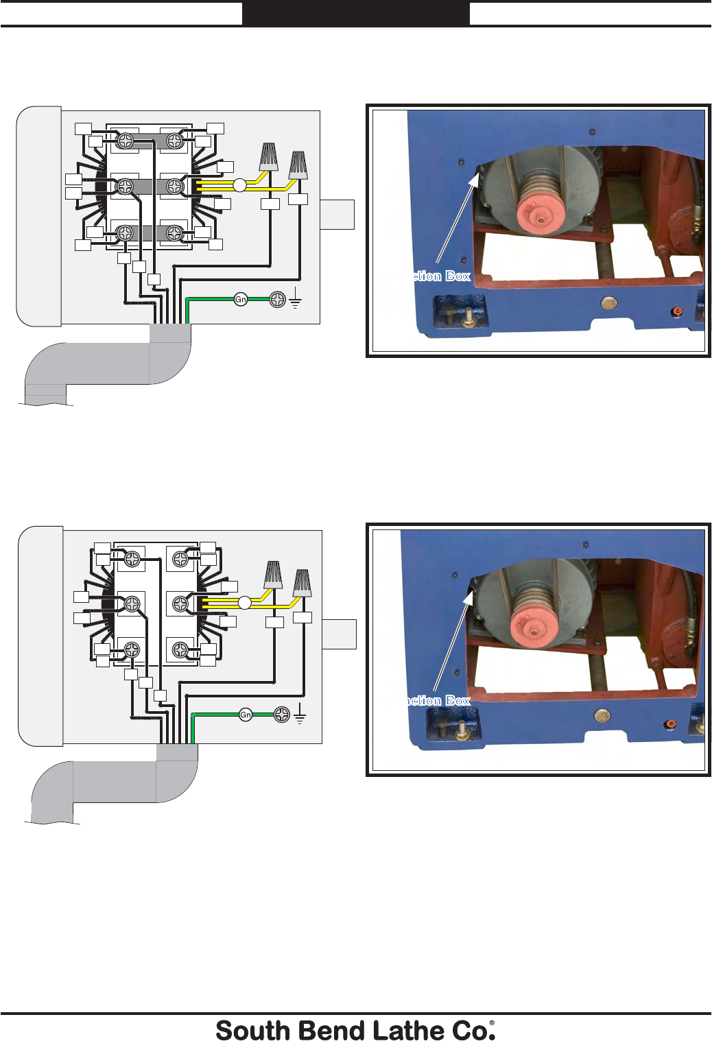
For Machines Mfg. Since 7/09 Model SB1016/SB1036
-97-
WARRANTY
SB1016 220V Spindle Motor
SB1036 440V Spindle Motor
spindle and pump
motor
Figure 164. SB1016 Spindle motor location.
Figure 165. SB1036 Spindle motor location.
SPINDLE
MOTOR (220V)
Ground
W
U1
U5
V1
V5
W5
W1
V6
V2
U2
W6
L13 L11
U6
W2
V
U
Yl
To Electrical
Box, Page 95.
SPINDLE
MOTOR (440V)
Ground
W
U1
V1
W1
V6
V2
U2
W6
U6
W2
V
U
Yl
U5
V5
W5
L13 L11
Junction Box
Junction Box
To Electrical Box,
Page 95.
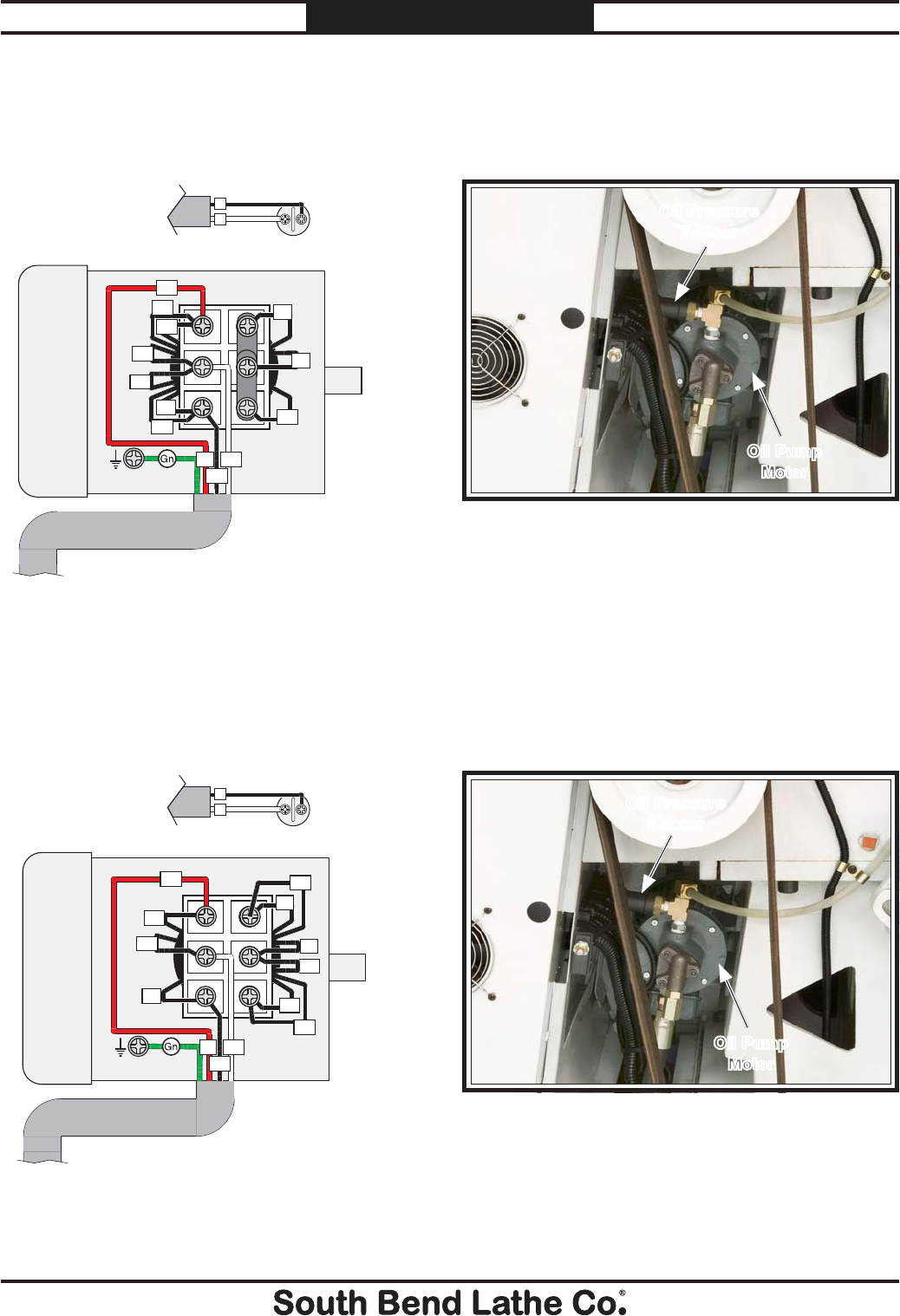
-98-
For Machines Mfg. Since 7/09
Model SB1016/SB1036 ELECTRICAL
SB1016 220V
Oil Pump Motor & Pressure Sensor
SB1036 440V
Oil Pump Motor & Pressure Sensor
Figure 166. SB1016 Oil pump motor & pressure
sensor location.
Figure 167. SB1036 Oil pump motor & pressure
sensor location.
Oil Pump
Motor
Oil Pressure
Sensor
Ground
OIL PUMP
MOTOR (220V)
V2
W2
U2
U1
U5
V1
V5
W5
W1
U2
U2 V2
W2
To Electrical
Box, Page
95.
Ground
OIL PUMP
MOTOR (440V)
V2
W2
U2
U1
V1
V5
W1
U2
U2 V2
W2
U5
W5
To Electrical
Box, Page
95.
X11
2OIL
PRESSURE
SENSOR
X11
2OIL
PRESSURE
SENSOR
To Electrical
Box, Page
95.
Oil Pump
Motor
Oil Pressure
Sensor
To Electrical
Box, Page 95.
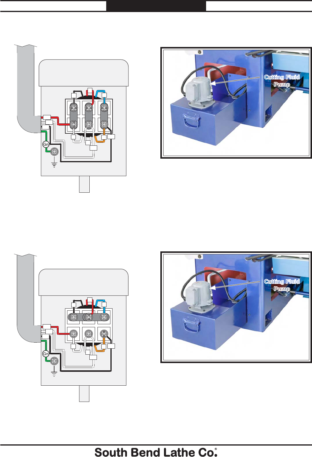
For Machines Mfg. Since 7/09 Model SB1016/SB1036
-99-
ELECTRICAL
Ground
CUTTING FLUID
PUMP MOTOR
(220V)
3
2
1
4
65W1
W1
V1
V1
U1
Ground
CUTTING FLUID
PUMP MOTOR
(440V)
Ground
3
2
1
4
65W1
W1
V1
V1
U1
SB1016 220V Cutting Fluid Pump Wiring
SB1036 440V Cutting Fluid Pump Wiring
Figure 168. SB1016 Cutting fluid pump location.
Figure 169. SB1036 Cutting fluid pump location.
Cutting Fluid
Pump
Cutting Fluid
Pump
To Electrical
Box, Page 95.
To Electrical
Box, Page 95.
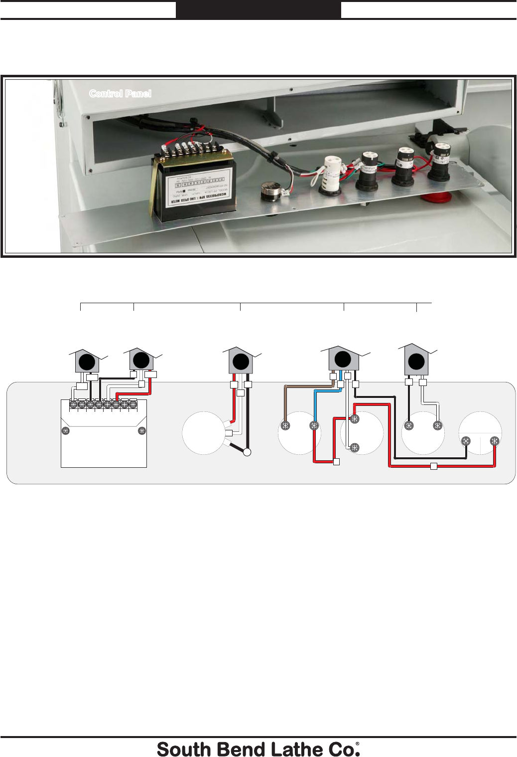
-100-
For Machines Mfg. Since 7/09
Model SB1016/SB1036 ELECTRICAL
SB1016/36 Control Panel Wiring
control panel
and
Figure 170. Control panel location.
Control Panel
220V
GND
IN
+12
110V
0V
Bk
X
X13
X14
COM
L
K
L11
1
33
TACHOMETER DISPLAY
SPINDLE
SPEED
DIAL
COOLANT
PUMP
SWITCH
JOG
BUTTON
POWER
LAMP
EMERGENCY
STOP
BUTTON
1
2
3
X1
X2
4
4
3
3
21
20
19
L13
2
3
12
4
19
SB1016/36 Control Panel Switches, Figure 170.
To Main Junction
Block, Page 94.
To Main Junction
Block, Page 94.
To Circuit Board,
Page 94.
To Circuit
Board, Page
94.
To Electrical
Box, Page 94.
DE
CB
A
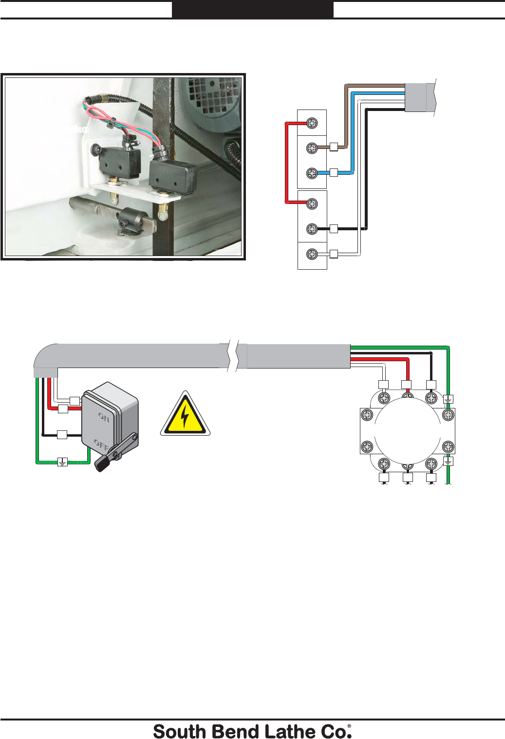
For Machines Mfg. Since 7/09 Model SB1016/SB1036
-101-
ELECTRICAL
SB1016/36 Spindle ON/OFF Switch
COMMON
NC
COMMON
NC
NO
NO
7
8
6
9
SB1016/36 Spindle ON/
OFF Switch, Figure 171.
spindle rotation
and power conn-
tection
SB1016/36 Power Connection
Ground
Hot
Hot
Hot DISCONNECT
SWITCH
(as recommended)L3
L2L1
MASTER
POWER SWITCH
L3
L3
L2
L2
L1
L1 1
2
35
6
4
Inside Electrical Box,
Page 95.
Figure 171. Spindle rotation switch location.
Spindle Rotation
Switches
To Main Junction
Block, Page 95.
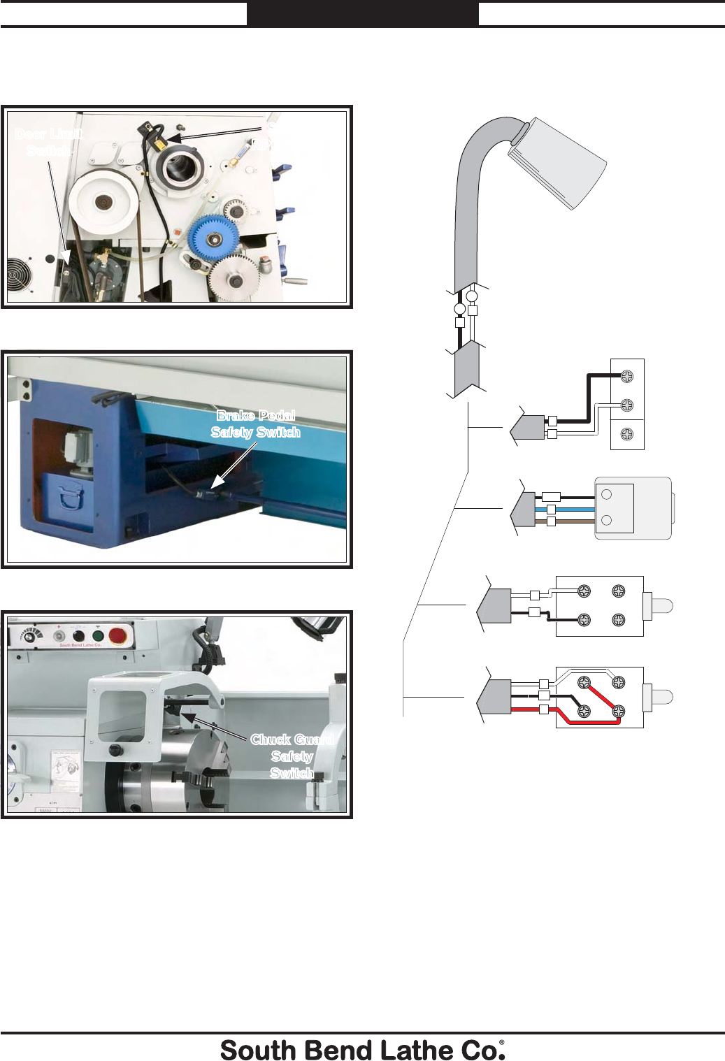
-102-
For Machines Mfg. Since 7/09
Model SB1016/SB1036 ELECTRICAL
Figure 172. RPM sensor and end gear cover safety
switch location.
Figure 173. Brake pedal safety switch location.
Figure 174. Chuck guard limit switch.
COMMON
NC
NO
A1
3
0
Bk
Wt
0
2
1314
2122
NC
NC
NO
NO
3
4
X5
A1
X9
1
K
L
COM
End Gear Cover Safety
Switch, Figure 172.
Work Light
Brake Limit Switch, Figure 173.
Spindle RPM Sensor, Figure 172.
Chuck Guard Safety Switch, Figure 174.
additional com-
pontnet
SB1016/36 Additional Component Wiring
Spindle
RPM Sensor
Door Limit
Switch
Brake Pedal
Safety Switch
Chuck Guard
Safety
Switch
To Electrical
Box, Page 95.
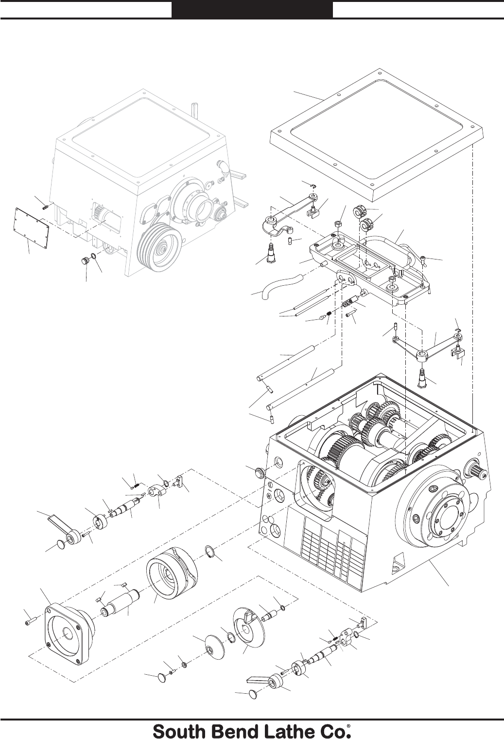
For Machines Mfg. Since 7/09 Model SB1016/SB1036
-103-
PARTS
Headstock Controls
12
3
4
5
6
7
8
9
10
11
12
13 14
15
16
17
18 19
21
22 23
24
25
26
28
29
30
32
34
35
36
38
39
40
41
42
43
44
45 46
47
48
49
50
51
52
53
54
55
56
1
1
2
3
4
5
6
7
89
10
11
12
29
8
34
29
32
PARTS

-104-
For Machines Mfg. Since 7/09
Model SB1016/SB1036 PARTS
Headstock Controls Parts List
REF PART # DESCRIPTION REF PART # DESCRIPTION
1 PSB10160001 SHIFTING SHAFT END CAP 29 PSB10160029 STEP PIN
2 PSB10160002 SHIFTING LEVER 30 PSB10160030 LONG SHIFTING ROD
3 PCAP38M CAP SCREW M5-.8 X 25 32 PEC03M E-CLIP 10MM
4 PSB10160004 SHIFTING SHAFT LOCK COLLAR 34 PSB10160034 SHIFTING PIVOT ARM BOLT
5 PK47M KEY 4 X 4 X 15 35 PSB10160035 RIGHT SHIFTING PIVOT ARM
6 PSB10160006 SHIFTING SHAFT 36 PSB10160036 RIGHT SHIFTING FORK
7 PK48M KEY 4 X 4 X 20 38 PSB10160038 SHORT SHIFTING ROD
8 PSB10160008 STEP PIN 39 PCAP176M CAP SCREW M6-1 X 30 BLK C12.9
9 PSB10160009 COMPRESSION SPRING 40 PSB10160040 INDENT BLOCK
10 PSB10160010 SHIFTING ARM 41 PSB10160041 SHIFTING PIN
11 PR07M EXT RETAINING RING 18MM 42 PSB10160042 NYLON OIL TUBE
12 PSB10160012 SHIFTING CAM 43 PSB10160043 SHIFTING SUPPORT FRAME
13 PFH06M FLAT HD SCR M6-1 X 20 44 PSB10160044 OIL PIPE
14 PSB10160014 END CAP BEVELED WASHER 45 PSB10160045 PIVOT ARM BOLT HEX NUT
15 PSB10160015 SPEED SELECTOR END CAP 46 PSB10160046 SHIFTING ROD LOCK COLLAR
16 PR15M EXT RETAINING RING 30MM 47 PCAP14M CAP SCREW M8-1.25 X 20
17 PSB10160017 SPEED SELECTOR HUB 48 PSB10160048 LEFT SHIFTING FORK
18 PSB10160018 CAM SHAFT 49 PSB10160049 LEFT SHIFTING PIVOT ARM
19 PSB10160019 O-RING G14 50 PSB10160050 HEADSTOCK TOP COVER
21 PCAP175M CAP SCREW M8-1.25 X 35 BLK C12.9 51 PSB10160051 HEADSTOCK CASTING
22 PSB10160022 SPEED SELECTOR CAM END CAP 52 PSB10160052 COMPRESSION SPRING
23 PK82M KEY 7 X 7 X 18 53 PORG035 O-RING 3.1 X 34.4 G35
24 PSB10160024 CAM SHAFT 54 PSB10160054 HEADSTOCK OIL DRAIN PLUG
25 PSB10160025 SPEED SELECTOR CAM 55 PSB10160055 HEADSTOCK SIDE COVER
26 PR12M EXT RETAINING RING 35MM 56 PSS21M SET SCREW M8-1.25 X 25
28 PSB10160028 HEADSTOCK OIL SIGHT GLASS
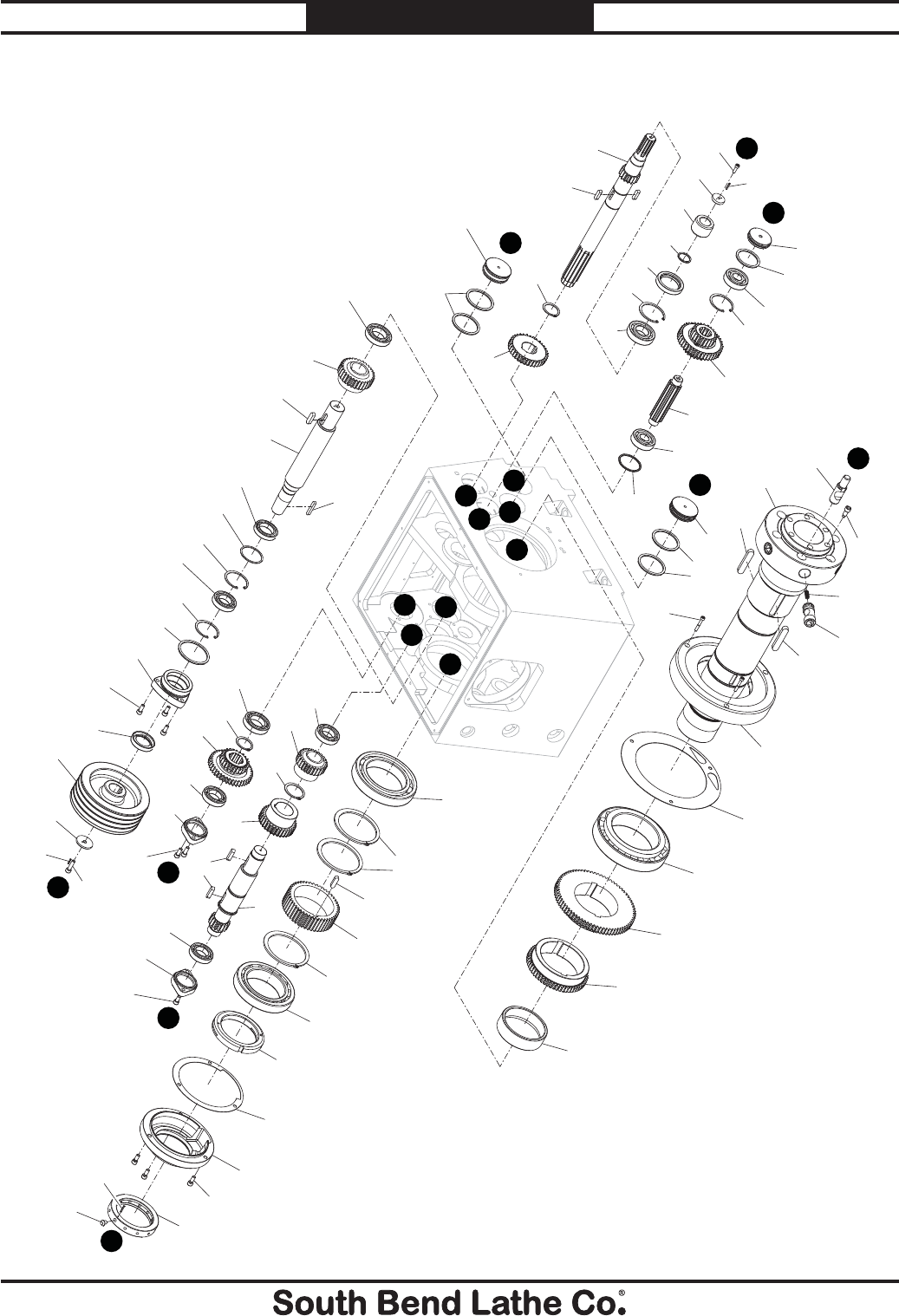
For Machines Mfg. Since 7/09 Model SB1016/SB1036
-105-
PARTS
Headstock Internal Gears
101
102
103
104
105
106
107
108
109
110
111
112
113
123
124
A
D
E
A
F
FA
D
E
CA
D
D
C
E
E
F
F
106
114
115
116
117
118
119
120
121
122
125
126
127
128
129
130
131
132
133
134
135
136
138
139
140
141
142
143
144
145
146
147
148
149
150
151
152
153
154
155
156
157
158
159
160
161
162
163
164
165
166
115
127
140
124
122
116
132
122
138 132
149
140
122
128 132
128
116
151

-106-
For Machines Mfg. Since 7/09
Model SB1016/SB1036 PARTS
Headstock Internal Gears Parts List
REF PART # DESCRIPTION REF PART # DESCRIPTION
101 PSB10160101 CAM LOCK STUD D1-8 134 PR32M EXT RETAINING RING 48MM
102 PSB10160102 SPINDLE NOSE CAP SCREW 135 PSB10160135 GEAR 32T
103 PSB10160103 SPINDLE 136 PSB10160136 GEAR SHAFT E 16T
104 PSB10160104 COMPRESSION SPRING 138 PSB10160138 BEARING RETAINER
105 PSB10160105 CAM LOCK D1-8 139 PCAP02M CAP SCREW M6-1 X 20
106 PSB10160106 KEY 15 X 10 X 78 140 PRP02M ROLL PIN 3 X 16
107 PCAP29M CAP SCREW M6-1 X 40 141 PSB10160141 GEAR FLAT WASHER
108 PSB10160108 INBOARD SPINDLE END CAP 142 PSB10160142 SPLINE SHAFT BUSHING
109 PSB10160109 BEARING SEAT GASKET 143 PORP030 O-RING 29.7 X 3.5 P30
110 P32026-N TAPERED ROLLER BEARING 32026 NTN 144 PSB10160144 OIL SEAL
111 PSB10160111 GEAR 75T 145 PR64M INT RETAINING RING 72MM
112 PSB10160112 GEAR 56T 146 P6207-2RS BALL BEARING 6207-2RS
113 PSB10160113 BEARING SPACER 147 PSB10160147 GEAR SHAFT D 16T
114 P6022-OPEN-N BALL BEARING 6022-OPEN NTN 148 PK136M KEY 8 X 8 X 30
115 PR90M EXT RETAINING RING 110MM 149 PR68M EXT RETAINING RING 40MM
116 PSB10160116 KEY 10 X 8 X 36 150 PSB10160150 GEAR 35T
117 PSB10160117 GEAR 48T 151 P6008-OPEN BALL BEARING 6008-OPEN
118 P32026-N TAPERED ROLLER BEARING 32026 NTN 152 PSB10160152 COMBO GEAR 25T/40T
119 PSB10160119 OUTBOARD SPINDLE SPANNER NUT 153 PSB10160153 BEARING END CAP
120 PSB10160120 OUTBOARD SPINDLE END CAP GASKET 154 PSB10160154 GEAR 31T
121 PSB10160121 OUTBOARD SPINDLE END CAP 155 PSB10160155 GEAR SHAFT A
122 PCAP14M CAP SCREW M8-1.25 X 20 156 PK62M KEY 7 X 7 X 45
123 PSB10160123 BEARING END CAP 157 P6908-OPEN BALL BEARING 6908-OPEN
124 PORG065 O-RING 64.4 X 3.1 G65 158 PSB10160158 THRUST WASHER
125 PSB10160125 BEARING END CAP 159 PORG075 O-RING 74.4 X 3.1 G75
126 PORG050 O-RING 54.4 X 3.1 G50 160 PSB10160160 BEARING RETAINER
127 P6305-OPEN BALL BEARING 6305-OPEN 161 PSB10160161 OIL SEAL
128 PR38M INT RETAINING RING 62MM 162 PSB10160162 SPINDLE PULLEY
129 PSB10160129 COMBO GEAR 21T/40T 163 PSB10160163 SPINDLE PULLEY FLAT WASHER
130 PSB10160130 SPLINE SHAFT 164 PCAP13M CAP SCREW M8-1.25 X 30
131 PSB10160131 THRUST WASHER 165 PSB10160165 EXCITER RING
132 P6007-OPEN BALL BEARING 6007-OPEN 166 PSB10160166 SENSOR EXCITER PIN
133 PSB10160133 GEAR 26T
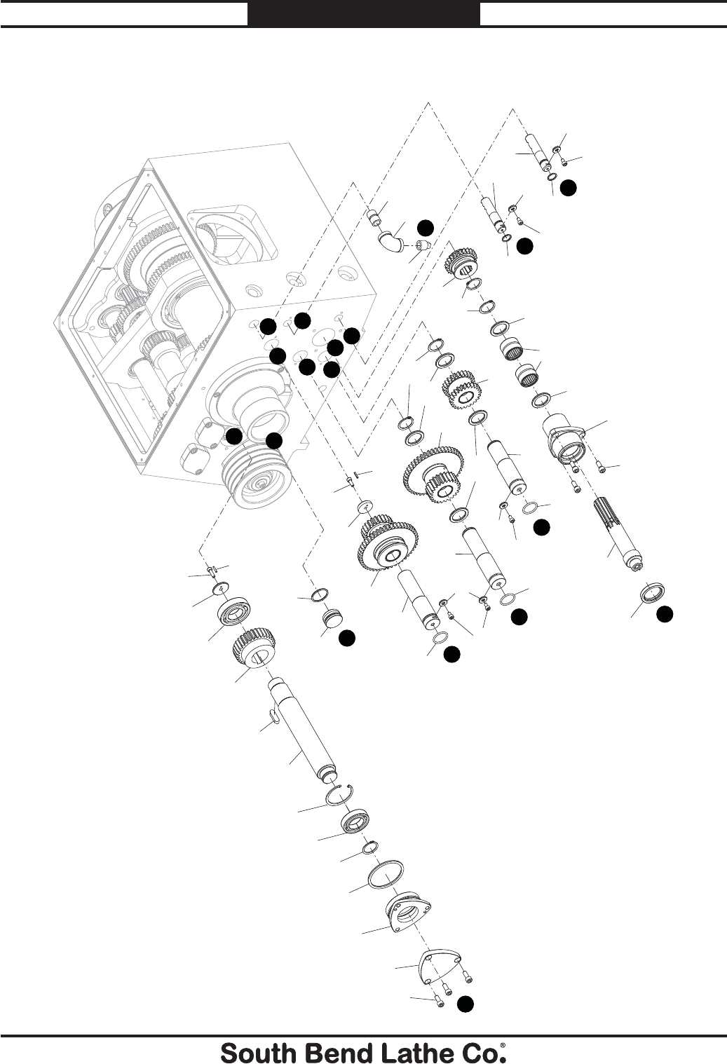
For Machines Mfg. Since 7/09 Model SB1016/SB1036
-107-
PARTS
Headstock Transfer Gears
C
B
G
H
I
J
L
K
M
C
BG
H
I
J
L
K
M
186
187
188
189
190
191
192
193
194
195
196
197
198 199
200
201
202
203
204 205
206
207
208
209
210
211
214
215
216
217
218
186
187
188
122
194
187
188
143
194
194
187
188
143
143
141
140
122
159
132
128
116
154
139
140

-108-
For Machines Mfg. Since 7/09
Model SB1016/SB1036 PARTS
Headstock Transfer Gears Parts List
REF PART # DESCRIPTION REF PART # DESCRIPTION
116 PSB10160116 KEY 10 X 8 X 36 197 PSB10160197 GEAR 24T
122 PCAP14M CAP SCREW M8-1.25 X 20 198 PSB10160198 SQUARE HD OIL DRAIN PLUG 1/2 PT
128 PR38M INT RETAINING RING 62MM 199 PSB10160199 PIPE ELBOW 90DEG 3/4 X 1/2 PT
132 P6007-OPEN BALL BEARING 6007-OPEN 200 PSB10160200 PIPE NIPPLE 3/4 PT X 1-1/4"
139 PCAP02M CAP SCREW M6-1 X 20 201 PSB10160201 GEAR SHAFT I
140 PRP02M ROLL PIN 3 X 16 202 PSB10160202 COMBO GEAR 24T
141 PSB10160141 GEAR FLAT WASHER 203 PR37M EXT RETAINING RING 32MM
143 PORP030 O-RING 29.7 X 3.5 P30 204 PSB10160204 GEAR SHAFT H
154 PSB10160154 GEAR 31T 205 PSB10160205 COMBO GEAR 24T/48T
159 PORG075 O-RING 74.4 X 3.1 G75 206 PSB10160206 GEAR SHAFT G
186 PSB10160186 O-RING G16 207 PSB10160207 DOUBLE GEAR 48T/24T
187 PCAP26M CAP SCREW M6-1 X 12 208 PCAP01M CAP SCREW M6-1 X 16
188 PSB10160188 GEAR SHAFT FLAT WASHER 209 PSB10160209 HEADSTOCK CASTING PLUG
189 PSB10160189 OUTBOUND SHAFT K 210 PORG035 O-RING 3.1 X 34.4 G35
190 PSB10160190 OUTBOUND SHAFT L 211 PR12M EXT RETAINING RING 35MM
191 PSB10160191 OIL SEAL 214 PSB10160214 SHAFT END CAP
192 PSB10160192 SPLINED SHAFT J 215 PSB10160215 BEARING RETAINER
193 PSB10160193 BEARING RETAINER 216 PSB10160216 SHAFT C
194 PSB10160194 THRUST WASHER 217 P6207-OPEN BALL BEARING 6207-OPEN
195 PSB10160195 NEEDLE BEARING W/O INNER RACE 3230 218 PSB10160218 BEARING FLAT WASHER
196 PR15M EXT RETAINING RING 30MM
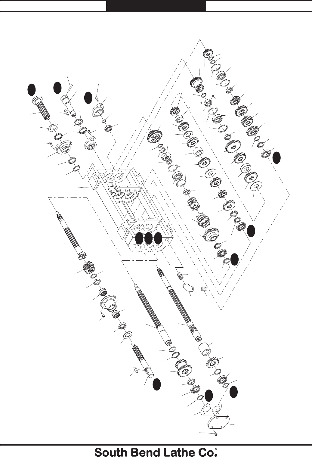
For Machines Mfg. Since 7/09 Model SB1016/SB1036
-109-
PARTS
Gearbox Gears
G1
G1
G2
G2
G3
G3
G3
G2
G1
G1
G2
G3
301
302
303 304
305
306
307
308
309
310
311
312
313
314 315
316 317
318
319
320
321
322
323
324
325
326
327
328
329
330
331
332
333
334
335
336 337 338
339 340
341 342
343 344
345
346
347
348
349
350
351
352
353
354
355
356357
358
359
360
361
362
363
364
365
366
367 368
369
370
371 372
305
306
309
309
314
318 426
427 428
318
315
306
306
302
306
314
324
314 308
329
330
314
324
309
333
329
330

-110-
For Machines Mfg. Since 7/09
Model SB1016/SB1036 PARTS
Gearbox Gears Parts List
REF PART # DESCRIPTION REF PART # DESCRIPTION
301 PSB10160301 OUTBOARD GEAR SHAFT G1 339 PSB10160339 THRUST WASHER
302 PK109M KEY 7 X 7 X 35 340 PSB10160340 GEAR 24T
303 PSB10160303 THRUST WASHER 341 PSB10160341 GEAR BUSHING
304 PSB10160304 OIL SEAL 342 PSB10160342 GEAR 23T
305 PSB10160305 GEAR SHAFT NEEDLE BEARING 343 PSB10160343 THRUST WASHER
306 PCAP177M CAP SCREW M6-1 X 16 BLK C12.9 344 PSB10160344 GEAR 27T
307 PSB10160307 BEARING RETAINER 345 PSB10160345 GEAR BUSHING
308 PSB10160308 SPACER 346 PSB10160346 GEAR 24T
309 PR11M EXT RETAINING RING 25MM 347 PSB10160347 THRUST WASHER
310 PSB10160310 DOUBLE CLUTCH GEAR 19T/19T 348 PSB10160348 GEAR 28T
311 PSB10160311 CLUTCH SPLINE SHAFT G1 349 PSB10160349 GEAR BUSHING
312 PSB10160312 BEARING RETAINER 350 PSB10160350 GEAR 26T
313 PSB10160313 SPLINE SHAFT COVER GASKET 351 PSB10160351 GEAR 32T
314 P16005-OPEN BALL BEARING 16005-OPEN 352 PSB10160352 LOCK COLLAR
315 PSB10160315 THRUST WASHER 353 PSS02M SET SCREW M6-1 X 6
316 PSB10160316 DOUBLE GEAR 20T/30T 354 PR10M EXT RETAINING RING 22MM
317 PSB10160317 GEAR WASHER 355 PSB10160355 DOUBLE GEAR 45T/18T
318 PR15M EXT RETAINING RING 30MM 356 PSB10160356 GEAR 22T
319 PSB10160319 SPLINE SHAFT G2 357 PSB10160357 GEAR 22T
320 PSB10160320 GEAR 22T 358 PSB10160358 GEAR 33T
321 PSB10160321 SPLINE SHAFT BUSHING 359 PSB10160359 GEAR 22T
322 PSB10160322 SPLINE SHAFT G3 360 PSB10160360 SPACER
323 PSB10160323 GEARBOX CASTING 361 PSB10160361 GEAR 36T
324 PSB10160324 THRUST WASHER 362 PSB10160362 INBOARD SHAFT SEAL RETAINER
325 PSB10160325 GEAR 32T 363 PSB10160363 OIL SEAL
326 PSB10160326 CLUTCH GEAR 23T 364 PSB10160364 KEYED SHAFT WASHER
327 PSB10160327 CLUTCH SPLINE 16T 365 PSB10160365 INBOARD SPLINE SHAFT G1
328 PSB10160328 SPACER 366 PSB10160366 CONNECTION SHAFT SEAL RETAINER
329 PR25M INT RETAINING RING 47MM 367 PSB10160367 THRUST WASHER
330 P6204-OPEN BALL BEARING 6204-OPEN 368 PSB10160368 FEED ROD CONNECTION SHAFT
331 PSB10160331 SPACER 369 PSB10160369 DOWEL PIN 6 X 36
332 PSB10160332 LEADSCREW CLUTCH 370 P16003-OPEN BALL BEARING 16003-OPEN
333 PR09M EXT RETAINING RING 20MM 371 PR18M EXT RETAINING RING 17MM
334 PSB10160334 DOUBLE CLUTCH GEAR 35T/35T 372 PSB10160372 BEARING RETAINER
335 PSB10160335 SPACER 426 PSB10160426 SQUARE HD OIL DRAIN PLUG 1/2 PT
336 PSB10160336 GEAR 22T 427 PSB10160427 PIPE ELBOW 90DEG 1/2 PT
337 PSB10160337 GEAR 16T 428 PSB10160428 PIPE NIPPLE 1/2 PT
338 PSB10160338 GEAR 20T
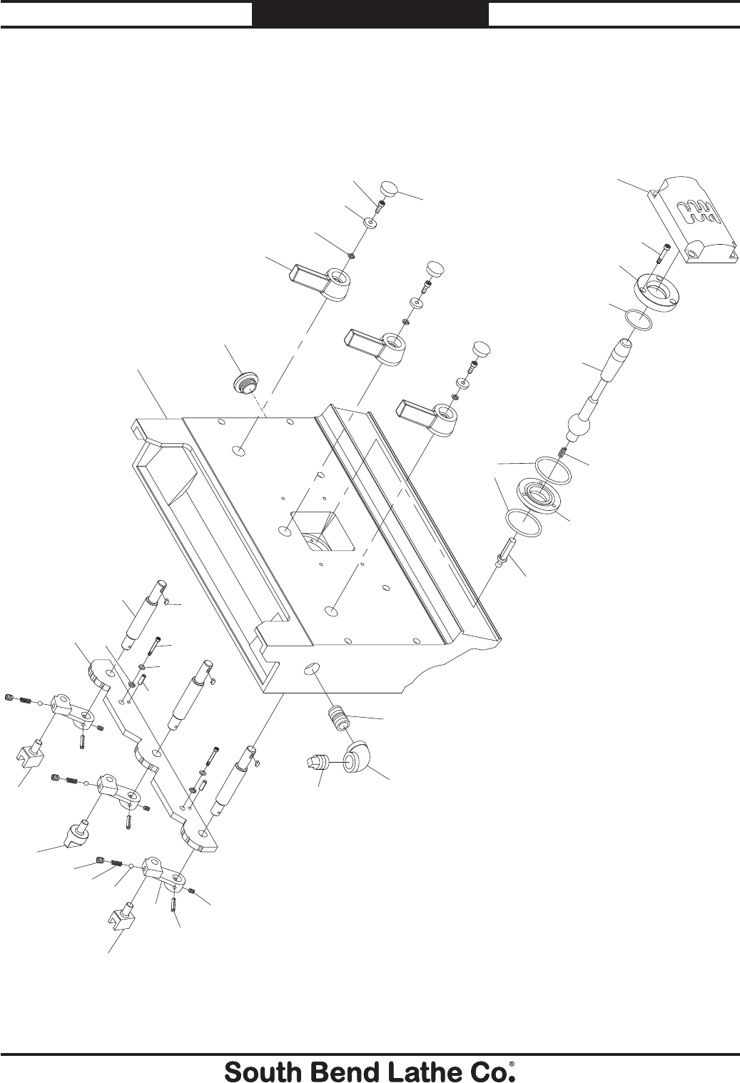
For Machines Mfg. Since 7/09 Model SB1016/SB1036
-111-
PARTS
Gearbox Controls A
396
397
398
399
400
401
402
403
404
405
406
407
408
409
410
411
412
413
414
415
416
417
418
419
420 421
422
423
424
425
429
431
373
373
377
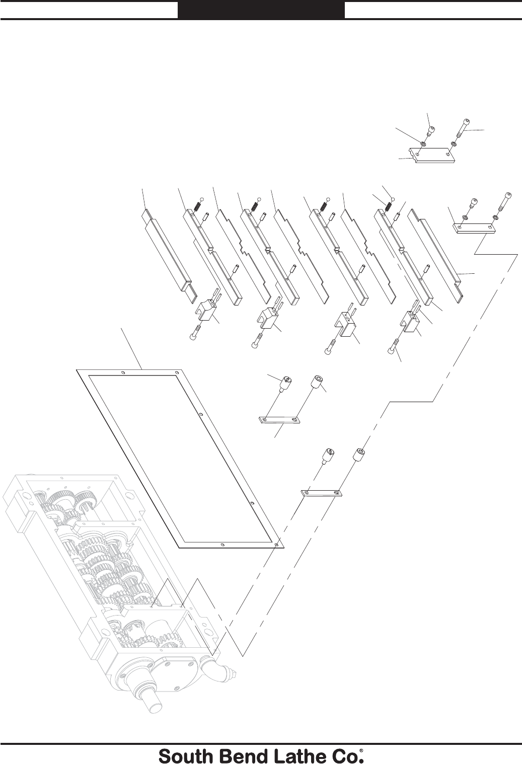
-112-
For Machines Mfg. Since 7/09
Model SB1016/SB1036 PARTS
Gearbox Controls B
373
374
375
376
377
378
380
381
382
383
384
385
386
387
388
389
390
391
392
393
394
395
430
432
376
385
385

For Machines Mfg. Since 7/09 Model SB1016/SB1036
-113-
PARTS
Gearbox Controls Parts List
REF PART # DESCRIPTION REF PART # DESCRIPTION
373 PSB10160373 STEP PIN LOCK WASHER 402 PSB10160402 SHIFT SELECTOR SUPPORT
374 PSB10160374 SHOULDER PLATE 403 PSB10160403 SHIFT SELECTOR PLUNGER
375 PSB10160375 REVERSE STOP 404 PSB10160404 SHIFT LEVER END CAP
376 PSB10160376 OUTER PLATE 405 PSB10160405 SHIFT LEVER FLAT WASHER
377 PSTB001 STEEL BALL 1/4 406 PSB10160406 SHIFT LEVER
378 PSB10160378 COMPRESSION SPRING 407 PSB10160407 OIL SIGHT GLASS
380 PRP24M ROLL PIN 5 X 16 408 PSB10160408 GEARBOX COVER
381 PSB10160381 BOTTOM FORK SUPPORT 409 PSB10160409 PIPE NIPPLE 3/4 PT
382 PRP24M ROLL PIN 5 X 16 410 PSB10160410 PIPE ELBOW 90DEG 3/4 PT
383 PSB10160383 BOTTOM SHIFT FORK 411 PSB10160411 SQUARE HD OIL FILL PLUG 3/4 PT
384 PCAP15M CAP SCREW M5-.8 X 20 412 PK05M KEY 4 X 4 X 10
385 PSB10160385 FORK SUPPORT PARTITION 413 PSB10160413 SHIFT CONNECTION SHAFT
386 PSB10160386 LOWER MIDDLE FORK SUPPORT 414 PSB10160414 SHIFT SELECTOR BAR
387 PSB10160387 LOWER MIDDLE SHIFT FORK 415 PSB10160415 SHIFT ARM
388 PSB10160388 UPPER MIDDLE FORK SUPPORT 416 PSB10160416 COMPRESSION SPRING
389 PSB10160389 UPPER MIDDLE SHIFT FORK 417 PSS20M SET SCREW M8-1.25 X 8
390 PSB10160390 TOP FORK SUPPORT 418 PSB10160418 RIGHT SHIFT FORK
391 PSB10160391 TOP SHIFTING FORK 419 PCAP02M CAP SCREW M6-1 X 20
392 PSB10160392 PLATE SPACER 420 PRP24M ROLL PIN 5 X 16
393 PSB10160393 SLOTTED STEP SCREW 421 PW03M FLAT WASHER 6MM
394 PSB10160394 SUPPORT PLATE 422 PSS02M SET SCREW M6-1 X 6
395 PSB10160395 GEARBOX COVER GASKET 423 PRP04M ROLL PIN 4 X 24
396 PSB10160396 SHIFT SELECTOR BRACKET 424 PSB10160424 MIDDLE SHIFT FORK
397 PSB10160397 SHIFT SELECTOR LOCK COLLAR 425 PSB10160425 LEFT SHIFT FORK
398 PORG035 O-RING 3.1 X 34.4 G35 429 PCAP26M CAP SCREW M6-1 X 12
399 PSB10160399 SHIFT LEVER 430 PCAP29M CAP SCREW M6-1 X 40
400 PSB10160400 COMPRESSION SPRING 431 PCAP38M CAP SCREW M5-.8 X 25
401 PORG040 O-RING 39.4 X 3.1 G40 432 PCAP01M CAP SCREW M6-1 X 16
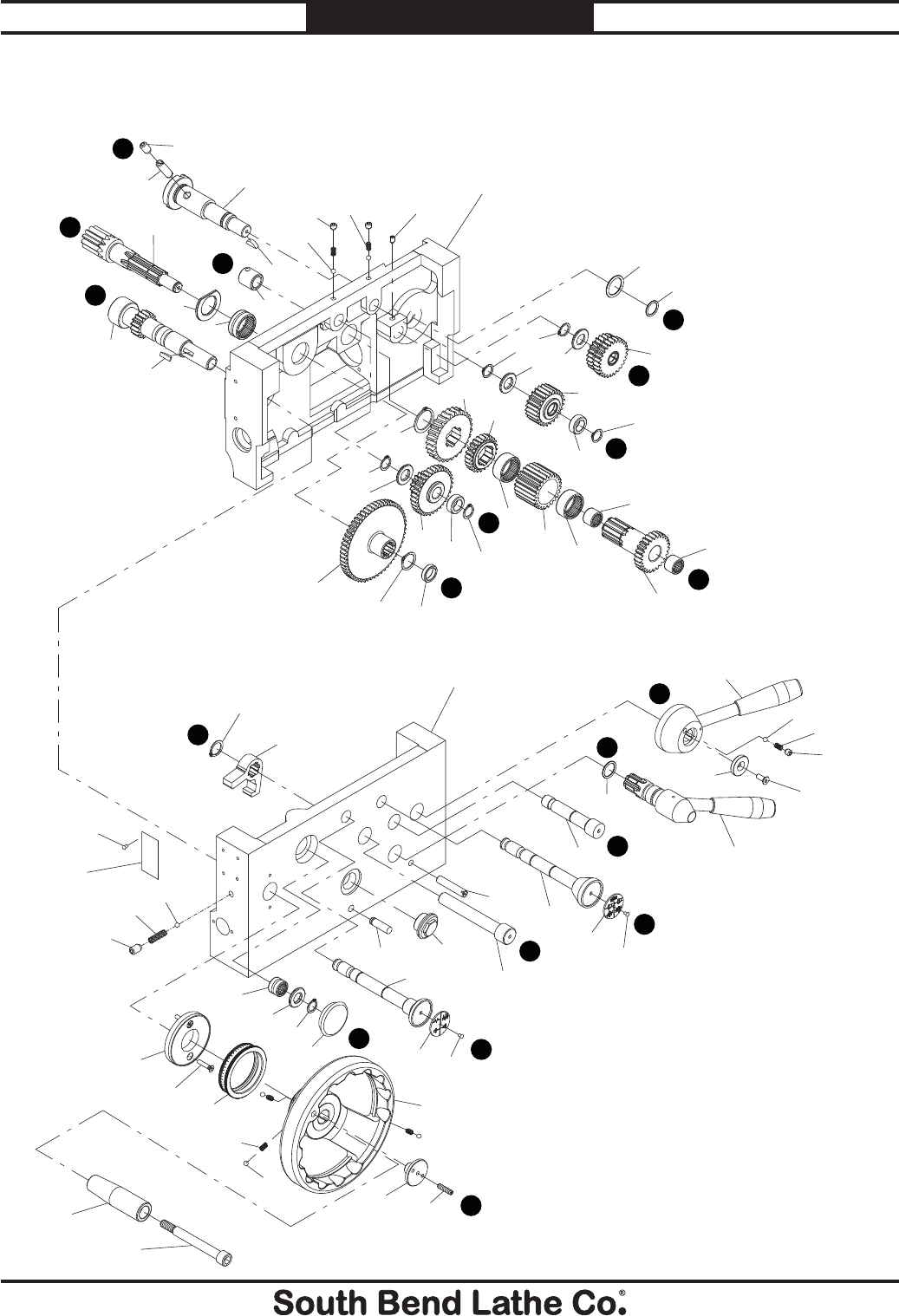
-114-
For Machines Mfg. Since 7/09
Model SB1016/SB1036 PARTS
Apron Front
H
B
D
A
B
C
D
E
H
F
H
G
F
E
D
C
B
A
G
501
502 503
504
505
506
507
508
509
510
511
512
513
514
515
516
517
518
519
523
524
525
526
527
528
529 530
531
532
533
534
535
536
537
538
540
541
542
543
545
546
547
548
549
550
551
552
553
554
555
557
564
565
566 567
523
506
514
514
532
534
514
526
514
528
548
520
521
522
539
558
559
560
561
562
563
635
553
506
523
636
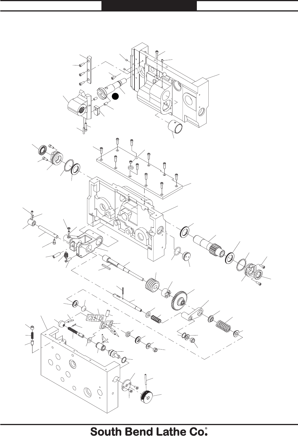
For Machines Mfg. Since 7/09 Model SB1016/SB1036
-115-
PARTS
Apron Rear
H
568
569
570
571
572
573
574
575
576
577
578
579
580 581 582
583
584
585
586
587
588
589
590
591
592
593
594
595
596
597
598
599
600
601
602
603
604
605
606
607
608
609
610
611 612
613
614
615 616
617
618 619
620
621
622 623
624 625
626
627
628
629
630
631
632
633
558
558
561
634
635
564
635
570
570
570
579
580
581
582
582
548
612
613
607
611

-116-
For Machines Mfg. Since 7/09
Model SB1016/SB1036 PARTS
Apron Parts List
REF PART # DESCRIPTION REF PART # DESCRIPTION
501 PSB10160501 HANDWHEEL HANDLE BOLT 547 PSB10160547 LEVER ASSEMBLY
502 PSB10160502 HANDWHEEL HANDLE 548 PORP021 O-RING 20.8 X 2.4 P21
503 PSS12M SET SCREW M6-1 X 25 549 PSB10160549 SHIFT FORK
504 PSB10160504 HANDWHEEL END CAP 550 PR81M EXT RETAINING RING 21MM
505 PSB10160505 HANDWHEEL 551 PFH73M FLAT HD CAP SCR M6-1 X 16
506 PSTB001 STEEL BALL 1/4 552 PSB10160552 LEVER HUB FLAT WASHER
507 PSB10160507 COMPRESSION SPRING 553 PSS20M SET SCREW M8-1.25 X 8
508 PSB10160508 INDEX RING 554 PSB10160554 COMPRESSION SPRING
509 PFH72M FLAT HD CAP SCR M5-.8 X 12 555 PSB10160555 HALF-NUT LEVER ASSEMBLY
510 PSB10160510 GEAR SHAFT END CAP 557 PSB10160557 O-RING G25
511 PSB10160511 WOODRUFF KEY 19 X 5 558 PSS03M SET SCREW M6-1 X 8
512 PSB10160512 GEARED SHAFT A 16T 559 PSB10160559 COMPRESSION SPRING
513 PSB10160513 SHAFT END CAP 560 PSB10160560 WOODRUFF KEY 16 X 5
514 PR07M EXT RETAINING RING 18MM 561 PSB10160561 CAM SHAFT H
515 PSB10160515 THRUST WASHER 562 PSS84M SET SCREW M10-1.5 X 35
516 PSB10160516 NEEDLE BEARING 18/20 563 PSS30M SET SCREW M10-1.5 X 10
517 PSB10160517 THRUST WASHER 564 PSB10160564 FRONT APRON CASTING
518 PR11M EXT RETAINING RING 25MM 565 PSS75M SET SCREW M10-1.5 X 16
519 PSB10160519 GEAR 56T 566 PSB10160566 COMPRESSION SPRING
520 PSB10160520 NEEDLE BEARING 28/20 567 PSTB003 STEEL BALL 3/8
521 PSB10160521 BEARING D-WASHER 568 PCAP26M CAP SCREW M6-1 X 12
522 PSB10160522 GEARED SHAFT B 11T 569 PSB10160569 HALF-NUT GIB
523 PSB10160523 SOLID STEEL RIVET 2.8 X 10 570 PCAP177M CAP SCREW M6-1 X 16 BLK C12.9
524 PSB10160524 INDICATOR PLATE 571 PCAP176M CAP SCREW M6-1 X 30 BLK C12.9
525 PSB10160525 SHIFT SHAFT C 572 PSB10160572 DOWEL PIN
526 PSB10160526 GEAR BUSHING 573 PSB10160573 HALF-NUT PLATE
527 PSB10160527 COMBO GEAR 15T/33T 574 PSB10160574 HALF-NUT ASSEMBLY
528 PSB10160528 GEAR WASHER 575 PCAP176M CAP SCREW M6-1 X 30 BLK C12.9
529 PSB10160529 DOWEL PIN 576 PSS28M SET SCREW M6-1 X 30
530 PSB10160530 OIL SIGHT GLASS 577 PSB10160577 OIL FILL PLUG 1/4 PT
531 PSB10160531 SHAFT D 578 PSB10160578 APRON TOP PLATE
532 PSB10160532 NEEDLE BEARING W/O INNER RACE 1616 579 PSB10160579 OIL SEAL 30 X 40 X 5
533 PSB10160533 GEARED SHAFT D 26T 580 PSB10160580 PINION SHAFT SEAL RETAINER
534 PSB10160534 NEEDLE BEARING W/O INNER RACE 3016 581 PORG045 O-RING 44.4 X 3.1 G45
535 PSB10160535 GEAR 24T 582 PSB10160582 THRUST BEARING 3047-NTB/AS2
536 PSB10160536 GEAR 24T 583 PSB10160583 GEARED PINION SHAFT 18T
537 PSB10160537 WORM GEAR 584 PSB10160584 CASTING PLUG
538 PR15M EXT RETAINING RING 30MM 585 PSB10160585 SHAFT LOCK COLLAR
539 PSB10160539 SHAFT LOCK COLLAR 586 PCAP26M CAP SCREW M6-1 X 12
540 PSB10160540 SLOTTED DOWEL PIN 587 PRP76M ROLL PIN 4 X 16
541 PSB10160541 INDICATOR PLATE 588 PSB10160588 BRACKET SHAFT
542 PSB10160542 SHIFT SHAFT (E) 589 PCAP38M CAP SCREW M5-.8 X 25
543 PSB10160543 GEAR 24T 590 PSB10160590 SLOTTED DOWEL PIN
545 PSB10160545 GEAR SHAFT (F) 591 PSB10160591 CAPTIVE PIN
546 PSB10160546 COMBO GEAR 24T/26T 592 PSB10160592 TENSION SPRING

For Machines Mfg. Since 7/09 Model SB1016/SB1036
-117-
PARTS
Apron Parts List
REF PART # DESCRIPTION REF PART # DESCRIPTION
593 PSS91M SET SCREW M6-1 X 14 615 PRP05M ROLL PIN 5 X 30
594 PLN03M LOCK HEX NUT M6-1 616 PW04M FLAT WASHER 10MM
595 PSB10160595 WORM SHAFT BRACKET 617 PLN05M LOCK NUT M10-1.5
596 PK33M KEY 5 X 5 X 45 618 PSB10160618 CUPPED BEARING
597 PSB10160597 WORM SHAFT 619 PRP04M ROLL PIN 4 X 24
598 PSB10160598 WORM GEAR 620 PRP02M ROLL PIN 3 X 16
599 PSB10160599 CLUTCH 621 PSB10160621 THREADED SHAFT
600 PSB10160600 CLUTCH GEAR 36T 622 PSB10160622 COMPRESSION PLATE WASHER
601 PSB10160601 PIVOT ARM 623 PRP105M ROLL PIN 3 X 24
602 PSB10160602 SPRING CAP 624 PSB10160624 COUPLING
603 PSB10160603 COMPRESSION SPRING 625 PSB10160625 STEP SHAFT
604 PSB10160604 SPRING CAP 626 PORP018 O-RING 17.8 X 2.4 P18
605 PRP04M ROLL PIN 4 X 24 627 PW03M SHAFT END CAP
606 PSB10160606 TRIP ROD 628 PFH74M FLAT HD CAP SCR M5-.8 X 16
607 PW06M FLAT WASHER 12MM 629 PRP10M ROLL PIN 5 X 36
608 PSB10160608 COMPRESSION SPRING 630 PSB10160630 KNURLED KNOB
609 PSB10160609 PIVOT ARM WASHER 631 PSB10160631 PLUNGER
610 PLN09M LOCK NUT M12-1.75 632 PSB10160632 COMPRESSION SPRING
611 PSB10160611 THRUST BEARING 1528-NTB/AS2 633 PSS15M SET SCREW M12-1.75 X 12
612 PSB10160612 CUPPED BEARING 634 PSB10160634 SHAFT SLEEVE
613 PSB10160613 COMPRESSION PLATE 635 PSB10160635 REAR APRON CASTING
614 PSB10160614 DOWEL PIN 636 PSB10160636 FEED CLUTCH INSTRUCTION PLATE
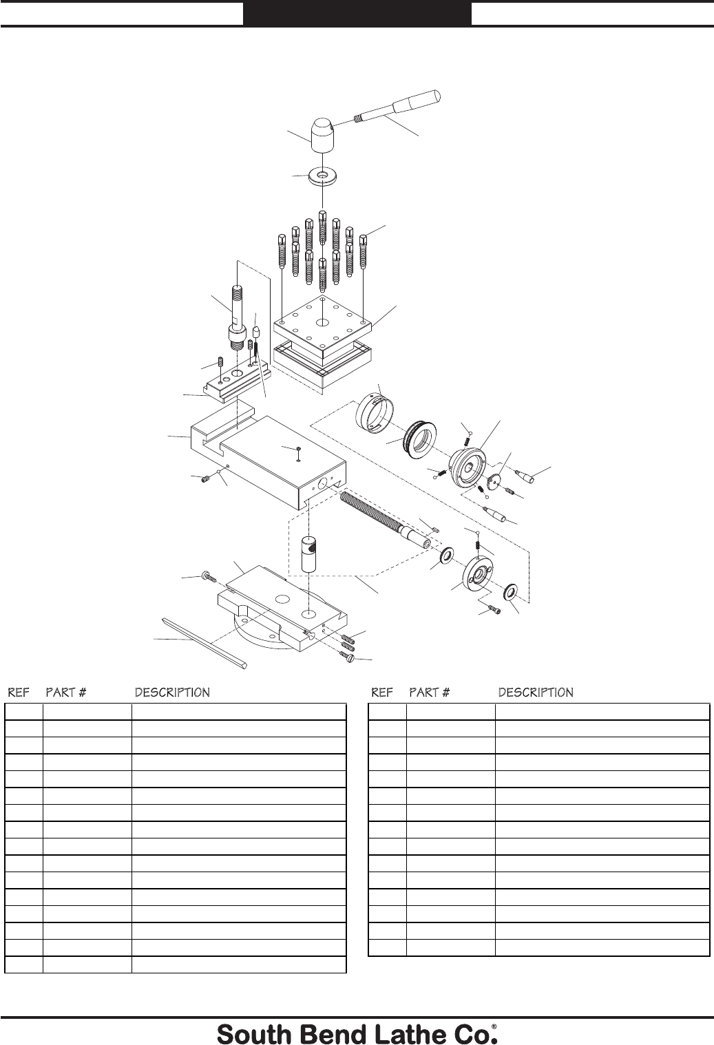
-118-
For Machines Mfg. Since 7/09
Model SB1016/SB1036 PARTS
Compound Slide & Tool Post
701
702
703
704
705
706
707
708
709
710
712
713
714
715
716
717
718
719
722
723
724
725
726
727
728
729
730
732
733
734
736A
716
714
723
714
725
REF PART # DESCRIPTION REF PART # DESCRIPTION
701 PSB10160701 POST HANDLE 718 PSB10160718 COMPOUND SWIVEL BASE
702 PSB10160702 POST HANDLE HUB 719 PSS19M SET SCREW M8-1.25 X 30
703 PSB10160703 POST FLAT WASHER 722 PK47M KEY 4 X 4 X 15
704 PSB10160704 TOOL POST SQUARE HD BOLT 723 PSB10160723 THRUST BEARING 2035-NTB/AS2
705 PSB10160705 POST TURRET 724 PSB10160724 LEADSCREW END CAP
706 PSB10160706 POST TURRET SHAFT 725 PSB10160725 COMPRESSION SPRING
707 PSB10160707 INDENT PLUNGER 726 PCAP179M CAP SCREW M6-1 X 20 BLK C12.9
708 PSB10160708 COMPRESSION SPRING 727 PSB10160727 INDEX COLLAR
709 PSS09M SET SCREW M8-1.25 X 20 728 PSB10160728 INDEX RING
710 PSB10160710 POST T-SLIDE 729 PSB10160729 COMPOUND HANDWHEEL
712 PSB10160712 COMPOUND SLIDE 730 PSB10160730 SHORT HANDWHEEL HANDLE
713 PSS06M SET SCREW M8-1.25 X 16 732 PSB10160732 HANDWHEEL END CAP
714 PSTB001 STEEL BALL 1/4 733 PSS25M SET SCREW M6-1 X 20
715 PLUBE001M TAP-IN BALL OILER 6MM 734 PSB10160734 LONG HANDWHEEL HANDLE
716 PSB10160716 GIB ADJUSTMENT SCREW 736A PSB10160736A COMPOUND LEADSCREW W/NUT
717 PSB10160717 COMPOUND SLIDE GIB
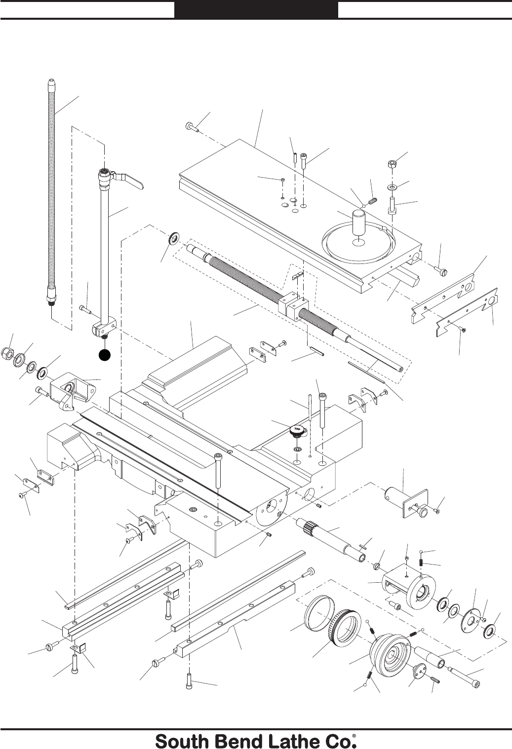
For Machines Mfg. Since 7/09 Model SB1016/SB1036
-119-
PARTS
Cross Slide & Saddle A
801 802
803 804
805
806
807
808
811
812A
813
814
815
816
817 818
819
820
821
822
823
824
825 826 827
828
829
830
831
832
833
834
835
836 837
838
839
840
841
842
843
844
864
858
859
860
874 861
862
801
863
863
857
863
872
859
831
870
832
830
831
858
869
868
801 860
871 873
801
842
865
808
866
X
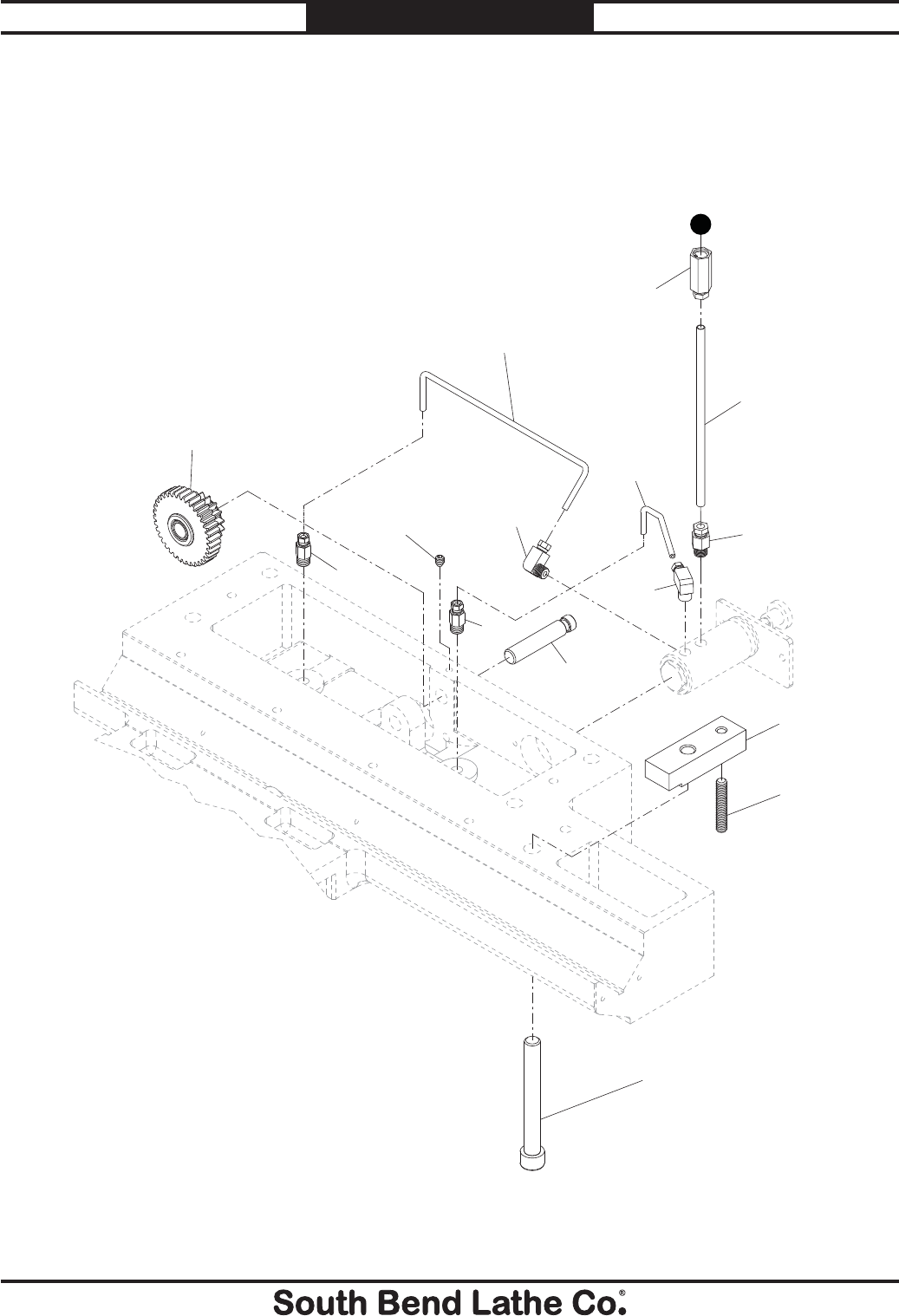
-120-
For Machines Mfg. Since 7/09
Model SB1016/SB1036 PARTS
Cross Slide & Saddle B
846
847
848
849
850
851
852
853
854
855
856
857
868
847
849
Viewed From Underneath Saddle
X

For Machines Mfg. Since 7/09 Model SB1016/SB1036
-121-
PARTS
Cross Slide & Saddle Parts List
REF PART # DESCRIPTION REF PART # DESCRIPTION
801 PSB10160801 GIB ADJUSTMENT SCREW 838 PSB10160838 HANDWHEEL END CAP
802 PSB10160802 CROSS SLIDE 839 PSB10160839 HANDWHEEL HANDLE
803 PSB10160803 COMPOUND PIVOT PIN 25 X 40 840 PSB10160840 HANDWHEEL HANDLE BOLT
804 PSB10160804 COMPOUND PIVOT T-BOLT 841 PSB10160841 FRONT SADDLE GIB BRACKET
805 PSB10160805 CROSS SLIDE GIB 842 PSB10160842 SADDLE GIB
806 PSB10160806 CROSS SLIDE WAY WIPER 843 PSB10160843 REAR SADDLE GIB BRACKET
807 PSB10160807 CROSS SLIDE WAY WIPER PLATE 844 PSB10160844 SADDLE OIL PUMP ASSEMBLY
808 PSB10160808 THRUST BEARING 1730-NTB/AS2 846 PSB10160846 COMBO GEAR 16T/36T
811 PRP28M ROLL PIN 5 X 40 847 PSB10160847 STRAIGHT PIPE ADAPTER 1/8 PT X 4MM
812A PSB10160812A CROSS SLIDE LEADSCREW W/NUT & KEY 848 PSB10160848 ALUMINUM OIL TUBE 4 X 258MM
813 PSB10160813 KEY 3 X 3 X 115 849 PSB10160849 ELBOW PIPE ADAPTER 18 PT X 4MM
814 PSB10160814 COOLANT NOZZLE 3/8 PT X 24" 850 PSB10160850 ALUMINUM OIL TUBE 4 X 121MM
815 PSB10160815 COOLANT STAND PIPE ASSY 3/8 PT 851 PSB10160851 GEAR SHAFT
816 PSB10160816 BEARING COLLAR 852 PSB10160852 STRAIGHT PIPE ADAPTER 1/8 PT X 6MM
817 PSB10160817 THRUST WASHER 853 PSB10160853 ALUMINUM OIL TUBE 6 X 175MM
818 PSB10160818 CROSS LEADSCREW END BRACKET 854 PSB10160854 OIL FILTER 6MM
819 PSB10160819 SADDLE CASTING 855 PSB10160855 CARRIAGE LOCK BLOCK
820 PSB10160820 SADDLE STRAIGHT WAY WIPER 856 PSS44M SET SCREW M8-1.25 X 40
821 PSB10160821 SADDLE STRAIGHT WAY WIPER PLATE 857 PCAP180M CAP SCREW M12-1.75 X 85 BLK C12.9
822 PSB10160822 OIL FILL PLUG 3/4 NF 858 PLUBE001M TAP-IN BALL OILER 6MM
823 PSB10160823 TAPER PIN #6 X 90MM 859 PSS12M SET SCREW M6-1 X 25
824 PSB10160824 SADDLE V-WAY WIPER 860 PCAP178M CAP SCREW M8-1.25 X 30 BLK C12.9
825 PSB10160825 SADDLE V-WAY WIPER PLATE 861 PW04M FLAT WASHER 10MM
826 PSB10160826 CROSS SLIDE PINION 16T 862 PN02M HEX NUT M10-1.5
827 PK96M KEY 3 X 3 X 20 863 PS08M PHLP HD SCR M5-.8 X 12
828 PSB10160828 PINION END PLUG 864 PCAP181M CAP SCREW M6-1 X 25 BLK C12.9
829 PSB10160829 PINION BRACKET 865 PLN07M LOCK NUT M16-2
830 PSB10160830 COMPRESSION SPRING 866 PCAP182M CAP SCREW M5-.8 X 25 BLK C12.9
831 PSTB001 STEEL BALL 1/4 868 PSS03M SET SCREW M6-1 X 8
832 PSB10160832 THRUST BEARING 2035-NTB/AS2 869 PCAP14M CAP SCREW M8-1.25 X 20
833 PSB10160833 THRUST WASHER 870 PS09M PHLP HD SCR M5-.8 X 10
834 PSB10160834 PINION BRACKET END PLATE 871 PCAP183M CAP SCREW M8-1.25 X 40 BLK C12.9
835 PSB10160835 INDEX COLLAR 872 PFH05M FLAT HD SCR M5-.8 X 12
836 PSB10160836 INDEX RING 873 PSB10160873 GIB SUPPORT PLATE
837 PSB10160837 CROSS SLIDE HANDWHEEL 874 PSS09M SET SCREW M8-1.25 X 20
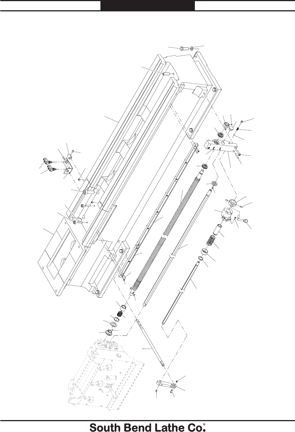
-122-
For Machines Mfg. Since 7/09
Model SB1016/SB1036 PARTS
Bed & Shafts
901
902
903
904
905
906
907
908
909
910
911
915
916
917
918
919
920
924
925
926
927
928
929
930
934
935
936
937
938
939
940
945
946
947
948
949
950
955
956
957
958
959
967
968
969
970
971
972
973
974
975
976
916
977
978
979

For Machines Mfg. Since 7/09 Model SB1016/SB1036
-123-
PARTS
Bed & Shafts Parts List
REF PART # DESCRIPTION REF PART # DESCRIPTION
901 PSB10160901 BED 938 PSB10160938 COMPRESSION SPRING
902 PSB10160902 GAP INSERT 939 PSTB003 STEEL BALL 3/8
903 PN09M HEX NUT M12-1.75 940 PCAP84M CAP SCREW M10-1.5 X 35
904 PSB10160904 TAILSTOCK STOP STUD 945 PSB10160945 TAPER PIN #7 X 50MM
905 PW08M FLAT WASHER M16-2 946 PSB10160946 SPINDLE LEVER HUB
906 PB80M HEX BOLT M16-2 X 55 947 PSB10160947 HUB STEP PIN
907 PCAP06M CAP SCREW M6-1 X 25 948 PSB10160948 SPINDLE LEVER ASSEMBLY
908 PRP08M ROLL PIN 6 X 30 949 PCAP01M CAP SCREW M6-1 X 16
909 PSB10160909 GAP RACK 950 PSB10160950 SPINDLE ROD SELECTOR HUB
910 PSB10160910 BED RACK 955 PSB10160955 SPINDLE ROD SLEEVE
911 PSB10160911 LEADSCREW LOCK NUT 956 PSB10160956 SPINDLE ROD COMPRESSION SPRING
915 PSS03M SET SCREW M6-1 X 8 957 PSB10160957 SPRING CAP
916 P51105 THRUST BEARING 51105 958 PR37M EXT RETAINING RING 32MM
917 PSB10160917 SHAFT END BRACKET 959 PSB10160959 SPINDLE ROD
918 PSB10160918 LONGITUDINAL LEADSCREW 967 PEC015M E-CLIP 8MM
919 PK99M KEY 6 X 6 X 15 968 PSB10160968 CONNECTING PIVOT ARM
920 PSB10160920 SPRING HOUSING 969 PSB10160969 CAPTIVE PIN
924 PSB10160924 COMPRESSION SPRING 970 PSS14M SET SCREW M8-1.25 X 12
925 PR37M EXT RETAINING RING 32MM 971 PSB10160971 CONNECTING ROD
926 PSB10160926 KEYED SHEAR PIN WASHER 972 PSB10160972 LOCK COLLAR
927 PSB10160927 SHEAR PIN 973 PCAP04M CAP SCREW M6-1 X 10
928 PSB10160928 LEADSCREW COLLAR 974 PCAP01M CAP SCREW M6-1 X 16
929 PSB10160929 FEED ROD END CAP 975 PSB10160975 SPINDLE SWITCH BRACKET
930 PLUBE001M TAP-IN BALL OILER 6MM 976 PSB10160976 SPINDLE SWITCH SET 2PC
934 PSB10160934 FEED ROD LOCK COLLAR 977 PSB10160977 THREADED TAPERED PIN M8-1.25 X 90
935 PSS01M SET SCREW M6-1 X 10 978 PCAP186M CAP SCREW M16-2 X 50 BLK C12.9
936 PSB10160936 FEED ROD 979 PSS20M SET SCREW M8-1.25 X 8
937 PSS15M SET SCREW M12-1.75 X 12
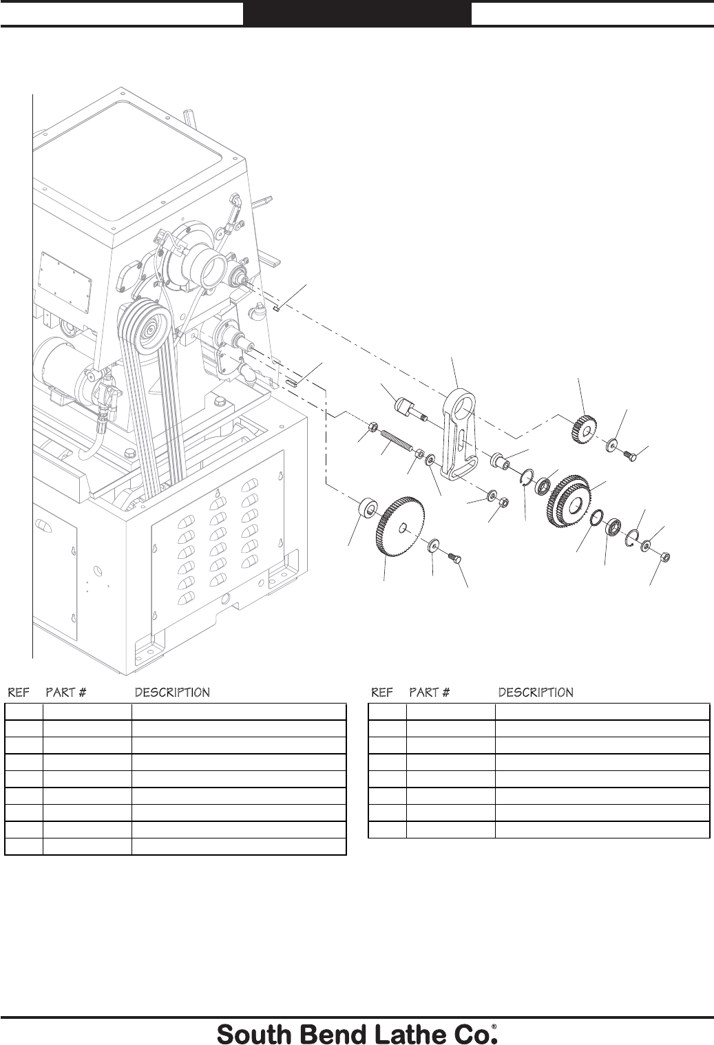
-124-
For Machines Mfg. Since 7/09
Model SB1016/SB1036 PARTS
End Gears
1001
1002
1003
1004
1005
1006
1007
1008
1009
1010
1011
1012
1013
1014
1015
1016
1017
1009
1008
1006
1007
1001
1002
1006
1006
REF PART # DESCRIPTION REF PART # DESCRIPTION
1001 PB176MM HEX BOLT M12-1.75 X 25 BLK C12.9 1010 PSB10161010 THRUST WASHER
1002 PSB10161002 GEAR FLAT WASHER 1011 PSB10161011 DOUBLE GEAR 44T/56T
1003 PSB10161003 GEAR 24T 1012 PSB10161012 GEAR SHAFT
1004 PSB10161004 PIVOT ARM 1013 PSB10161013 GEAR SHAFT T-PIN
1005 PK166M KEY 7 X 7 X 15 1014 PK109M KEY 7 X 7 X 35
1006 PN32M HEX NUT M14-2 1015 PSB10161015 ALL-THREAD STUD M14-2 X 110
1007 PW10M FLAT WASHER 14MM 1016 PSB10161016 GEAR 57T
1008 PR25M INT RETAINING RING 47MM 1017 PSB10161017 GEAR SPACER
1009 P6005ZZ BALL BEARING 6005ZZ
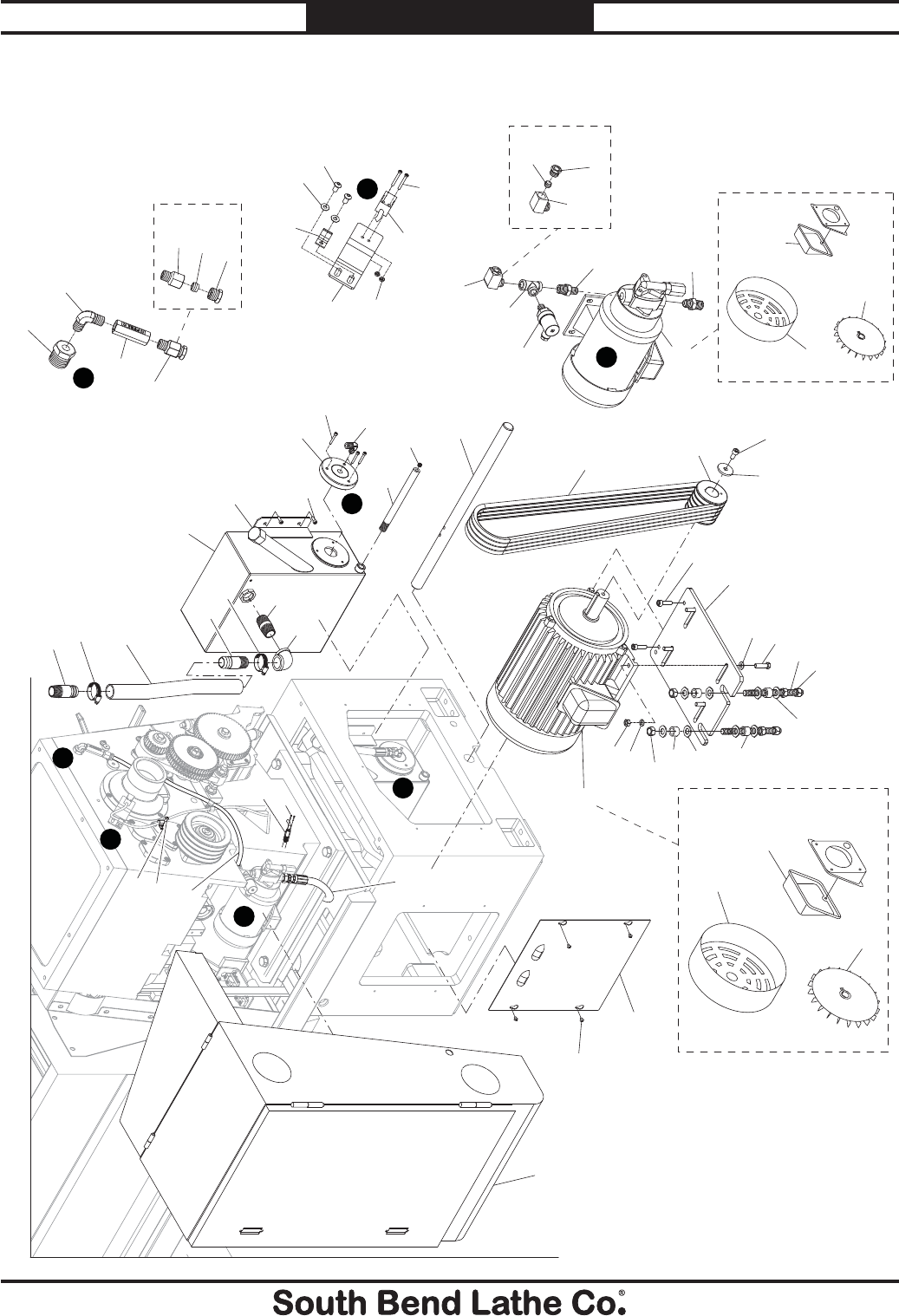
For Machines Mfg. Since 7/09 Model SB1016/SB1036
-125-
PARTS
Motor & Lubrication
D
C
B
A
A
D
C
B
1101
1102
1103
1104
1105
1106
1107 1108
1109
1110
1111
1111-1
1111-2
1111-3
1114
1115
1116
1117
1118
1119
1120
1122
1123
1124
1125
1126
1127
1128
1129
1130
1131
1132
1133
1134
1135
1136
1137 1138
1139
1140
1141
1142
1143
1144
1144-1
1144-2
1144-3
1145
1146
1147
1148 1149
1150
1151
1152
1101
1102 1106-1
1121
1153
1121
1131-1
1131-2
1131-3 1148-3
1148-1
1148-2
1134
1135
1132
1154
1155

-126-
For Machines Mfg. Since 7/09
Model SB1016/SB1036 PARTS
Motor & Lubrication Parts List
REF PART # DESCRIPTION REF PART # DESCRIPTION
1101 PSB10161101 STRAIGHT PIPE ADAPTER 1 PT X 3/4" 1131-1 PSB10161131-1 MOTOR FAN COVER
1102 PSB10161102 HOSE CLAMP 1" 1131-2 PSB10161131-2 MOTOR FAN
1103 PSB10161103 REINFORCED OIL HOSE 1" X 90" 1131-3 PSB10161131-3 MOTOR JUNCTION BOX
1104 PSB10161104 FEMALE 90 DEG PIPE ELBOW 1 PT 1132 PN13M HEX NUT M16-2
1105 PSB10161105 PIPE NIPPLE 1 PT X 2-1/2" 1133 PSB10161133 MOTOR MOUNT ALL-THREAD STUD
1106 PSB10161106 OIL TANK 1134 PSB10161134 MOTOR MOUNT FLAT WASHER 16.5 X 40MM
1106-1 PSB10161106-1 OIL FILL CAP 1135 PSB10161135 MOTOR MOUNT RUBBER CUSHION
1107 PCAP11M CAP SCREW M8-1.25 X 16 1136 PB31M HEX BOLT M10-1.5 X 40
1108 PSB10161108 OIL TANK SIDE COVER 1137 PW04M FLAT WASHER 10MM
1109 PSB10161109 FEMALE 90 DEG PIPE ELBOW 5/8 X 1/2 PT 1138 PSB10161138 MOTOR MOUNT PLATE
1110 PB151M HEX BOLT M5-.8 X 35 1139 PCAP64M CAP SCREW M10-1.5 X 25
1111 PSB10161111 OIL HOSE STRAIGHT CONNECTOR ASSY 1140 PLW06M LOCK WASHER 10MM
1111-1 PSB10161111-1 STRAIGHT HOSE CONNECTOR 1141 PN02M HEX NUT M10-1.5
1111-2 PSB10161111-2 CONNECTOR THIMBLE 1142 PSB10161142 MOTOR ACCESS COVER
1111-3 PSB10161111-3 THIMBLE NUT 1143 PS14M PHLP HD SCR M6-1 X 12
1114 PSB10161114 CHECK VALVE 1144 PSB10161144 OIL HOSE 90 DEG CONNECTOR ASSY
1115 PSB10161115 FEMALE 90 DEG PIPE ELBOW 1/4 X 1/4 PT 1144-1 PSB10161144-1 ELBOW CONNECTOR 3/8 PT X 16MM
1116 PSB10161116 PIPE ADAPTER 3/4 X 1/4 PT 1144-2 PSB10161144-2 CONNECTOR THIMBLE
1117 PSB10161117 OIL DRAIN PIPE 1144-3 PSB10161144-3 THIMBLE NUT
1118 PSB10161118 OIL DRAIN PLUG 1/4 PT 1145 PSB10161145 PIPE T-JOINT 3/8 PT
1119 PS68M PHLP HD SCR M6-1 X 10 1146 PSB10161146 OIL PRESSURE SWITCH
1120 PW02M FLAT WASHER 5MM 1147 PSB10161147 PIPE ADAPTER 3/8 X 1/4 PT
1121 PSB10161121 WIRE CLIP 10MM 1148 PSB10161148 OIL PUMP 1/4HP 220/440V 3PH
1122 PS98M PHLP HD SCR M3-.5 X 15 1148-1 PSB10161148-1 MOTOR FAN COVER
1123 PSB10161123 SPINDLE SPEED SENSOR 1148-2 PSB10161148-2 MOTOR FAN
1124 PN07M HEX NUT M3-.5 1148-3 PSB10161148-3 MOTOR JUNCTION BOX
1125 PSB10161125 SENSOR BRACKET 1149 PSB10161149 PIPE ADAPTER 3/8 X 1/2 PT
1126 PSB10161126 MOTOR MOUNT SHAFT 1150 PSB10161150 ELECTRICAL/CONTROL PANEL CABINET
1127 PCAP64M CAP SCREW M10-1.5 X 25 1151 PSB10161151 OIL HOSE 1/2"
1128 PSB10161128 PULLEY WASHER 12 X 45 X 5MM 1152 PSB10161152 OIL HOSE 10MM
1129 PSB10161129 MOTOR PULLEY 1153 PS05M PHLP HD SCR M5-.8 X 8
1130 PVA75 V-BELT A75 1154 PSB10161154 END GEAR COVER SAFETY SWITCH
1131 PSB10161131 MOTOR 10HP 220/440V 3PH 1155 PS65M PHLP HD SCR M4-.7 X 40
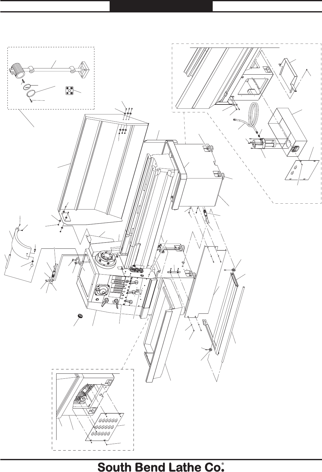
For Machines Mfg. Since 7/09 Model SB1016/SB1036
-127-
PARTS
Cabinets & Panels
1201
1202
1203 1204
1205 1206
1207
1208 1209 1210
1211
1212
1213
1214
1215
1216
1217
1218
1219 1220 1221
1222
1223
1224
1225
1226
1227
1228
1229
1230 1231
1232
1233
1234
1235
1236
1237
1238
1239
1240
1241
1242
1243
1244
1245
1246
1247 1248
1249
1205
1206
1223
1224
1225
1224
1225
1205
1204
1240
1250
1251
1253
1222
1252
1254
1254-1
1254-2
1254-3
1254-4
1254-5
1254-6

-128-
For Machines Mfg. Since 7/09
Model SB1016/SB1036 PARTS
Cabinets & Panels Parts List
REF PART # DESCRIPTION REF PART # DESCRIPTION
1201 PSB10161201 BRAKE PEDAL SHAFT 1231 PSB10161231 CHUCK GUARD
1202 PSB10161202 BRAKE PEDAL 1232 PCAP26M CAP SCREW M6-1 X 12
1203 PSB10161203 LOCK COLLAR 1233 PSS34M SET SCREW M5-.8 X 16
1204 PCAP01M CAP SCREW M6-1 X 16 1234 PSB10161234 COOLANT RETURN CHUTE
1205 PCAP04M CAP SCREW M6-1 X 10 1235 PSB10161235 COOLANT HOSE 3/8" X 78"
1206 PW03M FLAT WASHER 6MM 1236 PSB10161236 STRAIGHT PIPE NIPPLE 3/8 PT X 3/8 PH
1207 PSB10161207 CENTER PANEL 1237 PSB10161237 COOLANT PUMP 1/8HP 220/440V 3PH
1208 PSB10161208 CHIP DRAWER 1238 PSB10161238 COOLANT TANK
1209 PSB10161209 CENTER PANEL BRACKET 1239 PSB10161239 COOLANT TANK ACCESS PANEL
1210 PS05M PHLP HD SCR M5-.8 X 8 1240 PS68M PHLP HD SCR M6-1 X 10
1211 PSB10161211 ACCESS PANEL 1241 PSB10161241 RIGHT CABINET CHIP TRAY
1212 PSB10161212 SPINDLE SWITCH ACCESS PANEL 1242 PSB10161242 LEFT CABINET CHIP TRAY
1213 PSB10161213 SPLASH GUARD MOUNTING PLATE 1243 PSB10161243 LEFT CABINET SIDE ACCESS PANEL
1214 PSB10161214 CHUCK GUARD MOUNTING BRACKET 1244 PSB10161244 SPLASH GUARD MOUNTING BRACKET
1215 PB56M CAP SCREW M10-1.5 X 20 1245 PSB10161245 HEADSTOCK INFORMATION PANEL
1216 PSS14M SET SCREW M8-1.25 X 12 1246 PSB10161246 LEFT CABINET
1217 PN04M HEX NUT M4-.7 1247 PSB10161247 RIGHT CABINET
1218 PLW03M LOCK WASHER 6MM 1248 PSB10161248 CAST IRON FOOT PAD
1219 PCAP26M CAP SCREW M6-1 X 12 1249 PB80M HEX BOLT M16-2 X 55
1220 PSB10161220 SWITCH BRACKET 1250 PSB10161250 END GEAR COVER
1221 PSB10161221 CHUCK GUARD SAFETY SWITCH 1251 PSB10161251 COVER RETAINING KNOB
1222 PS65M PHLP HD SCR M4-.7 X 40 1252 PSB10161252 BRAKE SWITCH CAM
1223 PN03M HEX NUT M8-1.25 1253 PSB10161253 BRAKE SWITCH
1224 PW01M FLAT WASHER 8MM 1254 PSB10161254 HALOGEN LAMP ASSEMBLY
1225 PCAP14M CAP SCREW M8-1.25 X 20 1254-1 PSB10161254-1 LAMP BODY
1226 PSB10161226 SPLASH GUARD 1254-2 PSB10161254-2 HALOGEN BULB 24V
1227 PSB10161227 CHUCK GUARD KNOB 1254-3 PSB10161254-3 LENS
1228 PN06 HEX NUT 1/2-13 1254-4 PSB10161254-4 LENS RETAINER
1229 PB52 HEX BOLT 1/2-13 X 1 1254-5 PS55M PHLP HD SCR M3-.5 X 10
1230 PSB10161230 PIVOT ROD 1254-6 PSB10161254-6 LAMP TERMINAL BLOCK 2P
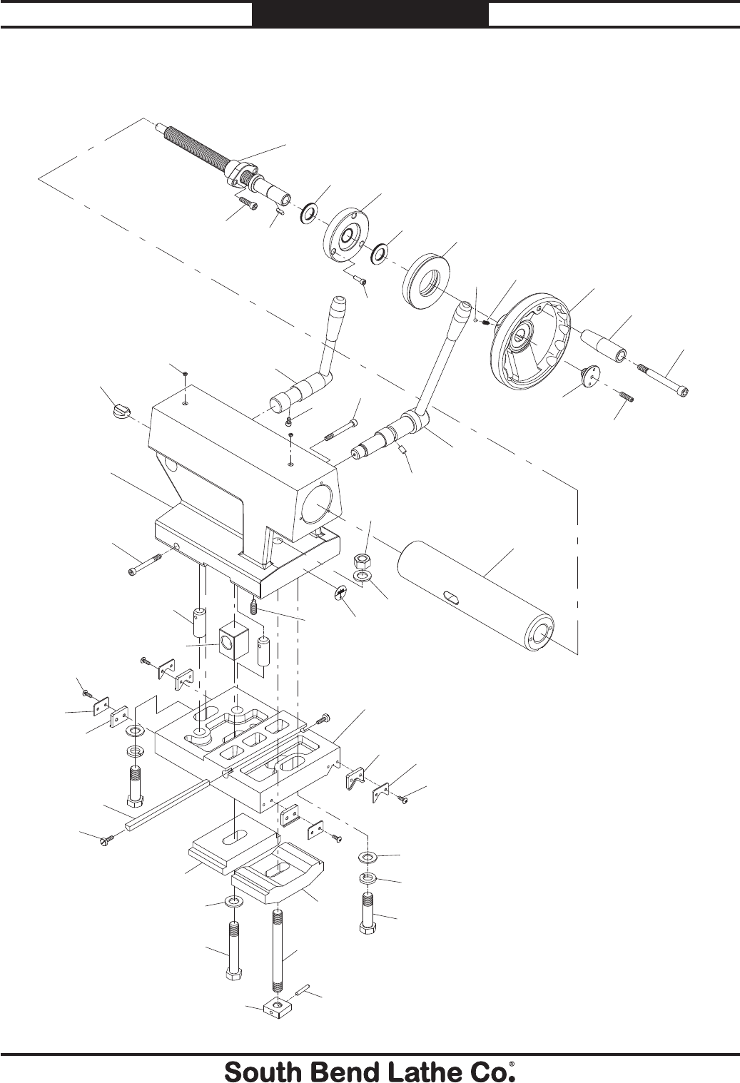
For Machines Mfg. Since 7/09 Model SB1016/SB1036
-129-
PARTS
Tailstock
1301
1302
1303
1304
1305
1306
1307
1308
1309 1310
1311
1312
1313
1314
1315
1316
1317
1318
1319 1320
1321
1322
1323
1324
1325
1326
1327
1328
1329
1330
1331 1332
1333
1334
1335
1336
1337
1338
1339
1340
1341
1342
1343
1344
1345
1346
1309
1319
1330
1325

-130-
For Machines Mfg. Since 7/09
Model SB1016/SB1036 PARTS
Tailstock Parts List
REF PART # DESCRIPTION REF PART # DESCRIPTION
1301 PSB10161301 HANDWHEEL HANDLE SCREW 1324 PN29M HEX NUT M18-2.5
1302 PSB10161302 HANDWHEEL HANDLE 1325 PW18M FLAT WASHER 18MM
1303 PSS19M SET SCREW M8-1.25 X 30 1326 PSB10161326 OFFSET INDICATOR PLATE
1304 PSB10161304 HANDWHEEL END CAP 1327 PSB10161327 DOG POINT SET SCREW M10-1.5 X 30
1305 PSB10161305 HANDWHEEL 1328 PSB10161328 ALIGNMENT STUD
1306 PSB10161306 COMPRESSION SPRING 1329 PSB10161329 PIVOT BLOCK
1307 PSTB001 STEEL BALL 1/4 1330 PS40M PHLP HD SCR M5-.8 X 16
1308 PSB10161308 INDEX RING 1331 PSB10161331 V-WAY WIPER
1309 PSB10161309 THRUST BEARING 3542-AS2 1332 PSB10161332 V-WAY WIPER PLATE
1310 PSB10161310 TAILSTOCK LEADSCREW FLANGE CAP 1333 PSB10161333 STRAIGHT WAY WIPER PLATE
1311 PCAP02M CAP SCREW M6-1 X 20 1334 PSB10161334 STRAIGHT WAY WIPER
1312 PSB10161312 TAILSTOCK LEADSCREW ASSEMBLY 1335 PSB10161335 TAILSTOCK BASE
1313 PK10M KEY 5 X 5 X 12 1336 PW18M FLAT WASHER 18MM
1314 PCAP178M CAP SCREW M8-1.25 X 30 BLK C12.9 1337 PLW12M LOCK WASHER 18MM
1315 PSB10161315 QUILL ALIGNMENT KEY 1338 PSB10161338 TAILSTOCK MOUNTING BOLT
1316 PLUBE001M TAP-IN BALL OILER 6MM 1339 PSB10161339 TAILSTOCK GIB
1317 PSB10161317 TAILSTOCK CASTING 1340 PSB10161340 GIB ADJUSTMENT SCREW
1318 PSB10161318 QUILL LOCK LEVER ASSEMBLY 1341 PSB10161341 TAILSTOCK TOP CLAMP PLATE
1319 PSB10161319 FULL THREAD CAP SCREW M6-1 X 10 1342 PSB10161342 BASE MOUNTING HEX BOLT
1320 PSB10161320 FULL THREAD CAP SCREW M8-1.25 X 70 1343 PSB10161343 TAILSTOCK BOTTOM CLAMP PLATE
1321 PSB10161321 TAILSTOCK LOCK LEVER ASSEMBLY 1344 PSB10161344 TAILSTOCK CLAMP STUD
1322 PSB10161322 DOWEL PIN 1345 PRP31M ROLL PIN 6 X 36
1323 PSB10161323 QUILL MT#5 1346 PSB10161346 TAILSTOCK CLAMP BLOCK SQUARE NUT
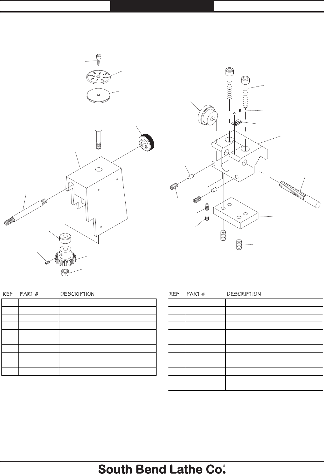
For Machines Mfg. Since 7/09 Model SB1016/SB1036
-131-
PARTS
Thread Dial
1401
1402
1403
1404
1405
1407
1408
1409
1410
1411
REF PART # DESCRIPTION
1401 PSB10161401 INDICATOR PLATE
1402 PSB10161402 GEAR SHAFT
1403 PSB10161403 DIAL INDICATOR CASTING
1404 PSB10161404 KNURLED KNOB
1405 PSB10161405 PIVOT STUD
1407 PSB10161407 GEAR SPACER
1408 PSB10161408 DIAL GEAR 16T BRASS
1409 PSB10161409 INDICATOR PLATE CAP SCREW
1410 PSS02M SET SCREW M6-1 X 6
1411 PSB10161411 GEAR SHAFT HEX NUT
Micrometer Stop
1451
1452
1453
1454
1455
1456
1457
1458
1459
1460
1461
1462
REF PART # DESCRIPTION
1451 PCAP185M CAP SCREW M10-1.5 X 60 BLK C12.9
1452 PSB10161452 SOLID STEEL RIVET 2.8 X 10
1453 PSB10161453 INDICATOR PLATE
1454 PSB10161454 KNURLED KNOB
1455 PSB10161455 BED STOP CASTING
1456 PSB10161456 BED STOP ADJUSTMENT STUD
1457 PSB10161457 CLAMP PLATE
1458 PSS10M SET SCREW M10-1.5 X 20
1459 PSB10161459 COPPER CUSHION
1460 PSS06M SET SCREW M8-1.25 X 16
1461 PSB10161461 DOG POINT SET SCREW M8-1.25 X 12
1462 PSS14M SET SCREW M8-1.25 X 12
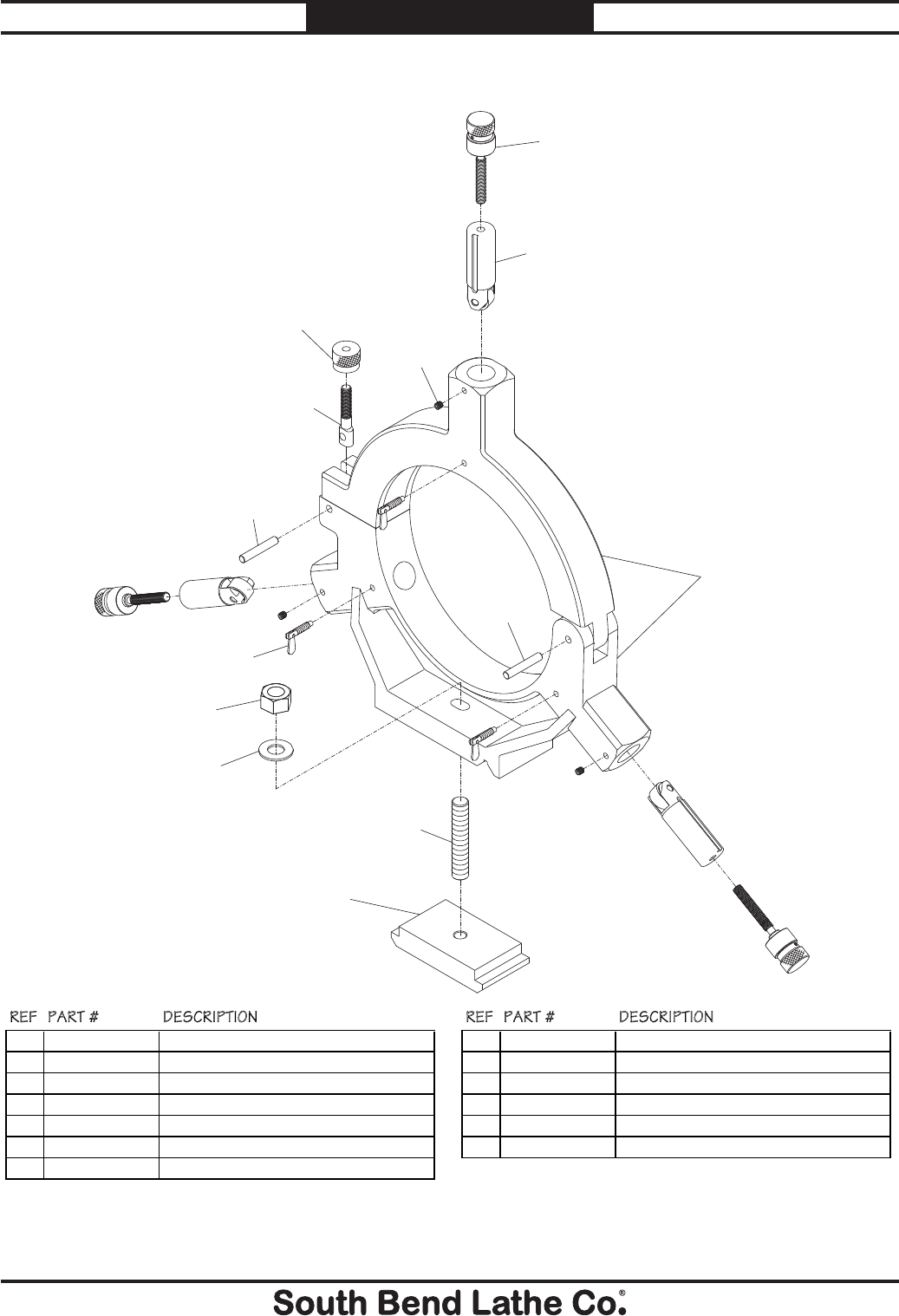
-132-
For Machines Mfg. Since 7/09
Model SB1016/SB1036 PARTS
Steady Rest
1501
1502
1503
1504
1505
1506
1507
1508
1509
1510
1511
1512
1513
REF PART # DESCRIPTION REF PART # DESCRIPTION
1501 PSB10161501 FINGER ADJUSTMENT KNOB SCREW ASSY 1508 PSB10161508 LEAF SCREW
1502 PSB10161502 STEADY REST FINGER ASSEMBLY 1509 PSB10161509 DOWEL PIN 10 X 53
1503 PSS20M SET SCREW M8-1.25 X 8 1510 PN29M HEX NUT M18-2.5
1504 PSB10161504 KNURLED KNOB 1511 PLW12M LOCK WASHER 18MM
1505 PSB10161505 CLAMP STUD 1512 PSB10161512 ALL-THREAD CLAMP STUD M18-2.5 X 100
1506 PSB10161506 STEADY REST CASTING ASSEMBLY 1513 PSB10161513 CLAMP PLATE
1507 PSB10161507 DOWEL PIN 10 X 53
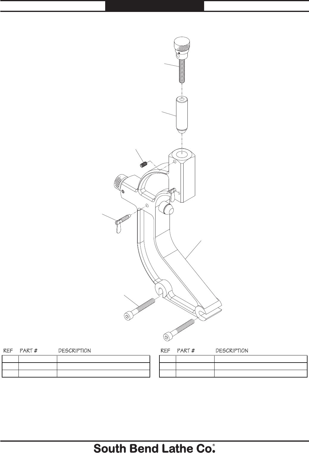
For Machines Mfg. Since 7/09 Model SB1016/SB1036
-133-
PARTS
Follow Rest
1551
1552
1553
1554
1555
1556
REF PART # DESCRIPTION REF PART # DESCRIPTION
1551 PSB10161551 FINGER ADJUSTMENT KNOB BOLT ASSY 1554 PSB10161554 FOLLOW REST CASTING
1552 PSB10161552 FOLLOW REST FINGER ASSEMBLY 1555 PSB10161555 LEAF SCREW
1553 PSS06M SET SCREW M8-1.25 X 16 1556 PCAP65M CAP SCREW M10-1.5 X 70
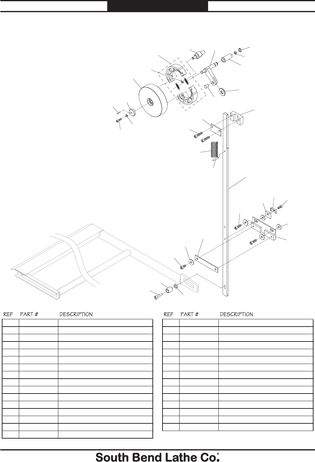
-134-
For Machines Mfg. Since 7/09
Model SB1016/SB1036 PARTS
Brake System
1601
1602
1604A 1605 1606
1607
1608
1609
1610
1611
1612
1613
1614
1615
1616
1617
1620
1621
1623
1624
1625
1628
1629
1630
16311632 1633
1634
1635
1636
1637
1629
REF PART # DESCRIPTION REF PART # DESCRIPTION
1601 PSB10161601 BRAKE DRUM 1620 PSB10161620 BOTTOM LINKAGE BRACKET PLATE
1602 PEC015M E-CLIP 8MM 1621 PCAP11M CAP SCREW M8-1.25 X 16
1604A PSB10161604A BRAKE SHOE SET W/SPRING 1623 PSB10161623 PIVOT SCREW HEX NUT
1605 PSB10161605 BRAKE SHOE ANCHOR PIN 1624 PSB10161624 AXLE ROLLER
1606 PSB10161606 PIVOT ARM 1625 PSB10161625 AXLE
1607 PSB10161607 PIVOT ARM BUSHING 1628 PCAP31M CAP SCREW M8-1.25 X 25
1608 PORP010 O-RING 9.8 X 1.9 P10 1629 PW01M FLAT WASHER 8MM
1609 PR02M EXT RETAINING RING 14MM 1630 PSB10161630 BOTTOM LINKAGE BRACKET
1610 PSB10161610 PIVOT ARM AXLE 1631 PSB10161631 PIVOT STOP
1611 PSB10161611 PIVOT ARM ROLLER 1632 PSB10161632 PIVOT STOP COVER
1612 PCAP40M CAP SCREW M8-1.25 X 35 1633 PCAP04M CAP SCREW M6-1 X 10
1613 PSB10161613 TOP LINKAGE BRACKET PLATE 1634 PSB10161634 BRAKE DRUM WASHER
1614 PSB10161614 BRAKE LINKAGE 1635 PRP02M ROLL PIN 3 X 16
1615 PSB10161615 TOP LINKAGE BRACKET 1636 PLW03M LOCK WASHER 6MM
1616 PSB10161616 COMPRESSION SPRING 1637 PCAP121M CAP SCREW M6-1 X 20 LH
1617 PSB10161617 DOWEL PIN 5 X 30
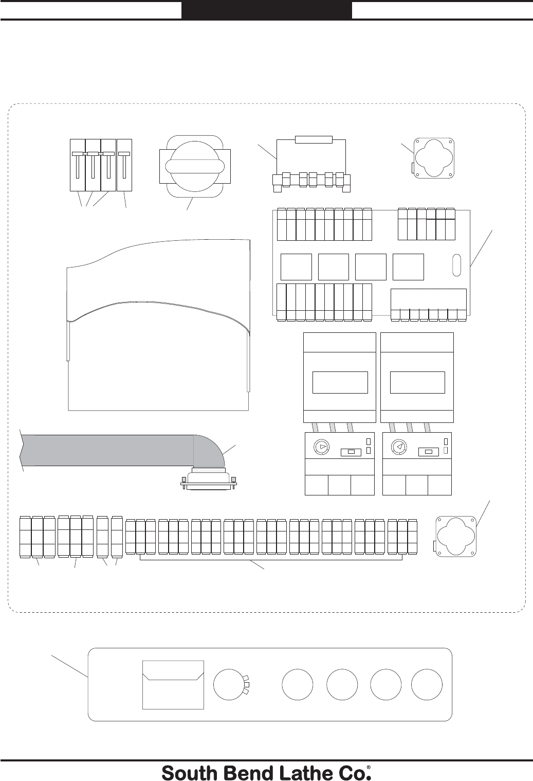
For Machines Mfg. Since 7/09 Model SB1016/SB1036
-135-
PARTS
Electrical Cabinet & Control Panel
Control Panel
Electrical Cabinet
1702 1703
1704 1705
1706
1707 1708
1709
1710
1711
1712 1713
1714
1717 1718 1719 1720 1721 1722
1723
1705
1707 1707
1711
1715 1715 1716
1724

-136-
For Machines Mfg. Since 7/09
Model SB1016/SB1036 PARTS
Electrical Cabinet & Control Panel Parts List
REF PART # DESCRIPTION REF PART # DESCRIPTION
1702 PSB10161702 CIRCUIT BREAKER AB SP3D320 20A 1713 PSB10132209 OL RELAY AB 193TAB10 0.6-1.0A (SB1036)
1703 PSB10161703 MAIN POWER SWITCH P1-32 (SB1016) 1714 PSB10161714 TERMINAL BOARD 3P SMALL
1703 PSB10361703 MAIN POWER SWITCH P1-25 (SB1036) 1715 PSB10161715 TERMINAL BOARD 3P LARGE
1704 PSB10161704 TRANSFORMER SUEN LIANG 0-440V 1716 PSB10161716 TERMINAL BOARD 1P LARGE
1705 PSB10161705 CABINET COOLING FAN 1717 PSB10161717 TACHOMETER DISPLAY
1706 PSB10161706 CIRCUIT BOARD 1718 PSB10161718 SPINDLE SPEED DIAL
1707 PSB10161707 RELAY OMRON MY4NJ 24V 1719 PSB10161719 POWER LAMP ASSEMBLY
1708 PSB10161708 RELAY OMRON MY2NJ 24V 1720 PSB10161720 COOLANT PUMP SWITCH
1709 PSB10161709 POWER INVERTER YASKAWA CMIR-G7A4011 1721 PSB10161721 SPINDLE JOG BUTTON
1710 PSB10161710 INVERTER/CIRCUIT BOARD CABLE 1722 PSB10161722 EMERGENCY STOP BUTTON
1711 PSB10161711 CONTACTOR AB C09400 24V 1723 PSB10161723 CIRCUIT BREAKER AB SP1D060 6A
1712 PSB10161712 OL RELAY AB 193-TAA40 0.24-0.4A 1724 PSB10161724 CONTROL PANEL PLATE
1713 PSB10122209 OL RELAY AB 193TAB24 1.6-2.5A (SB1016)
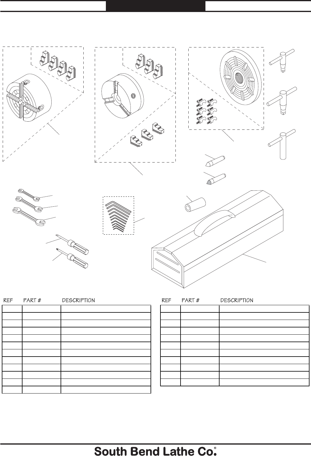
For Machines Mfg. Since 7/09 Model SB1016/SB1036
-137-
PARTS
Accessories
1801
1801-1
1801-2
1802
1802-1
1802-2
1804
1805
1806
1807
1808
1809
1802-3
1811
1812
1813
1814
1815
1816
1817
1803-1
1803-2
1803
REF PART # DESCRIPTION REF PART # DESCRIPTION
1801 PSB10161801 4-JAW CHUCK 14" ASSEMBLY 1806 PSB10161806 TOOL POST T-WRENCH
1801-1 PSB10161801-1 4-JAW CHUCK 14" 1807 PSB10161807 STANDARD DEAD CENTER MT#5
1801-2 PSB10161801-2 4-JAW CHUCK JAW SET 1808 PSB10161808 CARBIDE TIP DEAD CENTER MT#5
1802 PSB10161802 3-JAW CHUCK 12" ASSEMBLY 1809 PSB10161809 SPINDLE SLEEVE MT#5-MT#7
1802-1 PSB10161802-1 3-JAW CHUCK 12" 1811 PWR1012 WRENCH 10/12MM
1802-2 PSB10161802-2 3-JAW CHUCK STANDARD JAW SET 1812 PWR1417 WRENCH 14/17MM
1802-3 PSB10161802-3 3-JAW CHUCK REVERSIBLE JAW SET 1813 PWR2224 WRENCH 22/24MM
1803 PSB10161803 FACEPLATE ASSEMBLY 15" 1814 PSDF2 SCREWDRIVER FLAT #2
1803-1 PSB10161803-1 FACEPLATE 15" 1815 PSDP2 SCREWDRIVER PHILLIPS #2
1803-2 PSB10161803-2 FACEPLATE CAMLOCK STUD SET 1816 PAW1510M HEX WRENCH SET 10PC 1.5-10MM
1804 PSB10161804 3-JAW CHUCK KEY 1817 PSB10161817 TOOLBOX
1805 PSB10161805 4-JAW CHUCK KEY
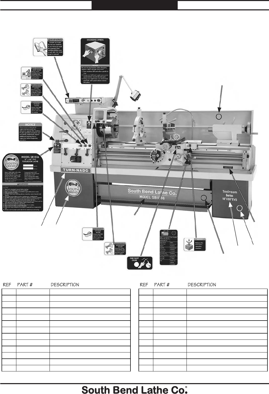
-138-
For Machines Mfg. Since 7/09
Model SB1016/SB1036 PARTS
Front Machine Labels
1901
1902
1903
1904
1905
1906
1907
1908
1909
1910
1911
1912
1913
1914
1915
1916
1917
1918
1903
1904
REF PART # DESCRIPTION REF PART # DESCRIPTION
1901 PSB10161901 MACHINE ID LABEL (SB1016) 1913 PSB10161913 SADDLE LOCK BOLT NOTICE LABEL
1901 PSB10361901 MACHINE ID LABEL (SB1036) 1914 PSB10161914 DIAL INDICATOR LABEL
1902 PSB10161902 TRAINED PERSONNEL NOTICE LABEL 1915 PSB10161915 ONE-SHOT OILER LABEL
1903 PSBLABEL04HS EYE INJURY LABEL 1916 PSB10161916 SB1016 MODEL NUMBER LABEL
1904 PSBLABEL08HS ENTANGLEMENT HAZARD LABEL 1916 PSB10361916 SB1036 MODEL NUMBER LABEL
1905 PSB10161905 CHUCK KEY HAZARD LABEL 1917 SB1322 SOUTH BEND NAMEPLATE
1906 PSBLABEL01HL READ MANUAL LABEL 1918 PSB10161918 TURN-NADO LABEL
1907 PSB10161907 CHANGING SPEEDS LABEL 1919 PSBLABEL06VS BIOHAZARD LABEL
1908 PSBPAINT01 SB GRAY TOUCH-UP PAINT 1920 PSBLABEL02HS INJURY/SHOCK HAZARD LABEL
1909 PSB10161909 BED CONSTRUCTION LABEL 1921 PSBLABEL15L ELECTRICITY LABEL
1910 PSBPAINT03 SB DARK BLUE TOUCH-UP PAINT 1922 PSB10161922 220V 3PH LABEL (SB1016)
1911 PSB10161911 TOOLROOM SERIES LABEL 1922 PSB10361922 440V 3PH LABEL (SB1036)
1912 PSBPAINT02 SB LIGHT BLUE TOUCH-UP PAINT 1923 PSB10161923 INVERTER WARNING LABEL
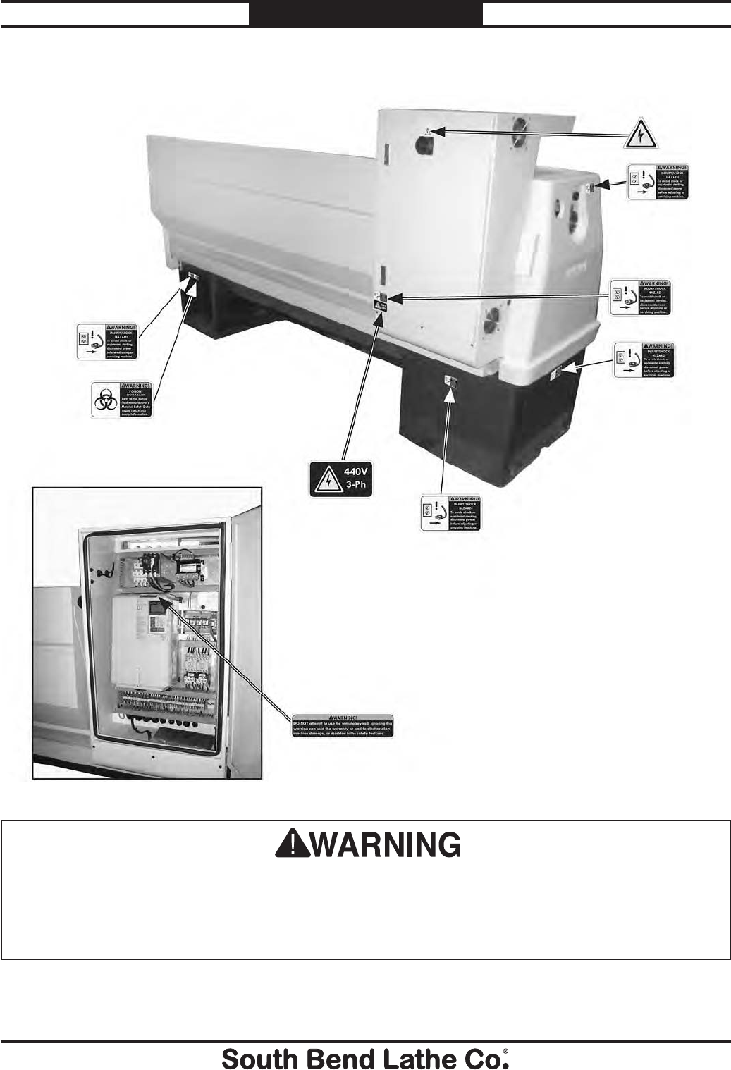
For Machines Mfg. Since 7/09 Model SB1016/SB1036
-139-
PARTS
The safety labels provided with your machine are used to make the operator aware of the
machine hazards and ways to prevent injury. The owner of this machine MUST maintain the
original location and readability of these safety labels. If any label is removed or becomes
unreadable, REPLACE that label before using the machine again. Contact South Bend Lathe Co. at
(360) 734-1540 or www.southbendlathe.com to order new labels.
Rear Machine Labels
1919
1920
1921
1922
1923
1920
1920
1920
1920

-140-
For Machines Mfg. Since 7/09
Model SB1016/SB1036

WARRANTY & RETURNS
For Machines Mfg. Since 7/09 Model SB1016/SB1036
-141-
WARRANTY
This quality product is warranted by South Bend Lathe Company to the original buyer for one year
from the date of purchase. This warranty does not apply to consumable parts, or defects due to any
kind of misuse, abuse, negligence, accidents, repairs, alterations or lack of maintenance. We do not
reimburse for third party repairs. In no event shall we be liable for death, injuries to persons or
property, or for incidental, contingent, special or consequential damages arising from the use of our
products.
We do not warrant or represent that this machine complies with the provisions of any law, act, code,
regulation, or standard of any domestic or foreign government, industry, or authority. In no event
shall South Bend’s liability under this warranty exceed the original purchase price paid for this
machine. Any legal actions brought against South Bend Lathe Company shall be tried in the State of
Washington, County of Whatcom.
This is the sole written warranty for this machine. Any and all warranties that may be implied by
law, including any merchantability or fitness, for any purpose, are hereby limited to the duration of
this warranty. To take advantage of this warranty, contact us by mail or phone to give us the details
of the problem you are having.
Thank you for your business and continued support.
Warranty

South Bend Lathe Co.
P.O. Box 2027
Bellingham, WA 98227
PHONE: (360) 734-1540 (Administrative Offi ces)
FAX: (360) 676-1075 (International)
FAX: (360) 734-1639 (USA only)
southbendlathe.com
Printed In Taiwan #CRTSJB12960
