Southco H3EM69 Electronic Swinghandle User Manual General open questions
Southco,. Inc Electronic Swinghandle General open questions
Southco >
Users Manual
H3-EM-69-100 Electronic Swinghandle
Operating Instructions
J-H3-EM-69-100-M_revB Page 1 of 4
Package Contents
H3-EM-69-x00 Electronic Swinghandle (qty1)
EM-0-45827 M3x25 POZIDRIV® Mounting Screws (qty 4)
EM-0-47151 M3x14 POZIDRIV® Mounting Screw (qty 1)
EM-0-45825 Rotation Limiter (qty 1)
E5-C-04 Pawl Screw (qty 1)
M3-0-24943-11 Lock Plug Screw (qty 1) (optional)
EM-0-45826 Top Mounting Bracket (qty 1)
EM-0-45822 Bottom Mounting Bracket (qty 1)
Operating Instructions (qty 1)
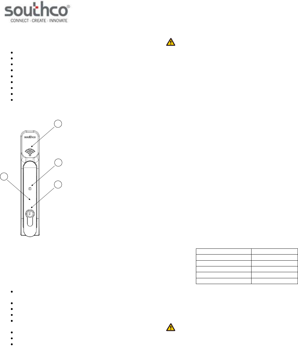
H3-EM-69-x00 Electronic Swinghandle
3
4
1
2
1. Handle
2. Prox Reader
3. Tri-Color Status LED
4. Lock Plug (optional)
Features
Installed 125kHz proximity reader module with RS232 data
output
Remote lock and unlock capability
Single or multi-point lock actuation
Momentary or continuous lock actuation
Tri-color LED (blue/magenta/red) to indicate lock and handle
status
DIN lock manual override
Accommodates both left and right doors
For indoor use only
WARNING: The H3-EM-69-000 is shipped without a lockplug. This
product must be paired with a Southco-approved lock to function properly.
Use with an unapproved lockplug voids the product warranty.
Contact Southco for additional support.
Specifications
Actuator Module
Supply Voltage (VSUPPLY): 12VDC to 24VDC (NOTE: Status LED will blink
red if the supply voltage is out of range.)
Standby Current: 50mA maximum at 12VDC
Operating Current: 200mA maximum at 12VDC (with no external
mechanical load applied to handle
Stall Current: 1A maximum (at 12VDC, limited to 2 seconds)
Operating Transit Time: 1 second maximum (NOTE: Power must be
present during transit times. If power is
removed while the lock slide is moving to the
unlock position, then the control input signal
must be asserted again. If power is removed
while the lock slide is moving to the lock
position, it will complete it’s cycle when power is
restored.)
Electronic Unlock Time: 3 seconds minimum
Open Collector Outputs: Rated for VSUPPLY, 100mA maximum load
Proximity Reader Module
Supply Voltage (VCC): 12VDC to 24VDC
Operating Current: 50mA maximum (no external devices
attached)
Transmit Frequency: 125kHz FSK
TX Data Output Voltage: -12VDC / +12VDC
COM Port Settings:
parameter
setting
bits per second
9600
data bits
8
parity
none
stop bits
1
flow control
none
Mounting and Installation
Please refer to Southco trade drawing J-H3-EM-69-100 for mounting and
installation details.
NOTE: Use a #1 POZIDRIV® driver when installing the mounting
screws. See Southco trade drawing J-H3-EM-69-100 for additional details.
H3-EM-69-100 Electronic Swinghandle
Operating Instructions
J-H3-EM-69-100-M_revB Page 2 of 4
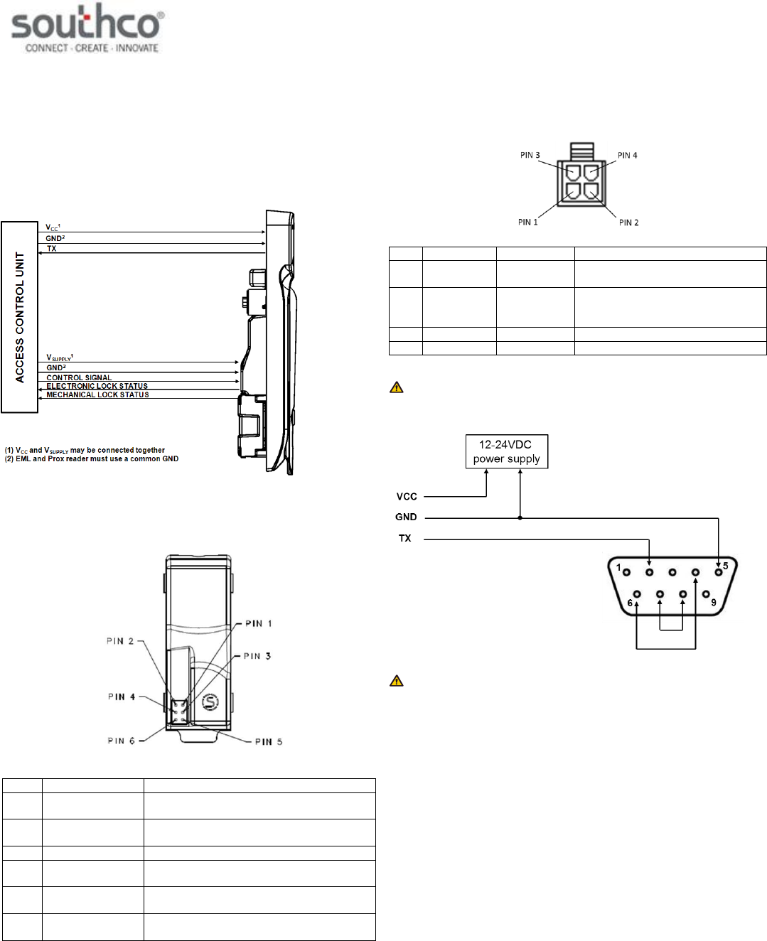
Wiring Diagrams
The H3-EM-69-x00 contains two separate functional modules: the actuator
module and proximity reader module. The actuator module controls and
monitors the locking function of the swinghandle.
These two modules operate independently of each other and require
connection to an access control unit (not provided), as illustrated below,
for the entire product to be fully functional.
The actuator module of the swinghandle is accessed with a six-position
connector on the rear of the unit, shown below.
Pin
Description
Note
1
VGND
ground (must be same as proximity reader
module)
2
VSUPPLY
12 to 24 VDC power supply input (may be
connected to prox reader VCC input)
3
N/C
no connect
4
Control Signal
command input (9VDC up to supply
voltage, 50 milliseconds minimum)
5
Electronic Lock
Status
open collector output (rated for VSUPPLY,
100mA max. load)
6
Mechanical Lock
Status
open collector output (rated for VSUPPLY,
100mA max. load)
The proximity reader module of the swinghandle is accessed with a four-
position connector attached to a harness connected to the module’s circuit
board. The module’s connector pinout is:
Pin
Wire Color
Description
Note
1
Black
GND
ground (must be same as actuator
module)
2
Red
VCC
12 to 24VDC power supply input
(may be connected to EML VSUPPLY
input)
3
Green
TX
data transmit
4
n/c
n/c
not connected
NOTE: If connecting the H3-EM-69’s TX data output to the DB9
connector of a computer, use the wiring configuration shown below.
NOTE: The mating connectors/harnesses are not provided with the
H3-EM-69-x00. Refer to Southco trade drawing J-H3-EM-69-100 for
mating connector/harness requirements.
H3-EM-69-100 Electronic Swinghandle
Operating Instructions
J-H3-EM-69-100-M_revB Page 3 of 4
Proximity Module Data Output (TX)
The proximity module will read a compatible card and output the ASCII
code for the hexadecimal equivalent (not including parity bits). Refer to the
Specifications section for the required RS232 COM port settings.
Example: A 26-bit card with the following content is presented to the
reader:
The reader will disregard the two parity bits, and convert the remaining bits
to their hexadecimal equivalent:
Fh
6h
0h
0h
2h
0h
The output of the reader will be the ASCII code of the hexadecimal
equivalent:
30h
32h
30h
30h
36h
46h
NOTE: The proximity reader will output a total of ten ASCII characters. If
the card does not support ten ASCII characters, then any unused
characters be “0” (ASCII code 30h).
Control Input Signal
This signal is used to control the electronic lock slide position.
for UNLOCKED position: Supply 9VDC minimum (do not exceed
supply voltage) for at least 50 milliseconds. The lock will remain
unlocked for as long as the signal is present, or a minimum of 3
seconds. Signal timing can typically be adjusted at the access
control device. The control signal current draw is less than
10mA.
for LOCKED position: Supply an open contact or 0VDC (0 to
0.5V)
Electronic Lock Status Output and Mechanical Lock Status Output
Signals
Electronic Lock Status Output Signal
This output will be LOW (GND) when the lock slide is electromechanically
moved to the unlocked position. It will be in the open collector state (high-
impedance) when in the locked position.
Mechanical Lock Status Output Signal
This output will be LOW (GND) when the handle is in the open position or
when the keylock in the actuator is manually unlocked. It will be in the
open collector state (high-impedance) when in the secured position.
NOTE: These outputs are open collector outputs rated for VSUPPLY with
a maximum load of 100mA. To avoid damage to the H3-EM, do not
exceed voltage and current ratings.
Status LED and Output Signals
The latch is equipped with a tri-color (blue/magenta/red) LED visible from
the front of the latch. This LED provides a visible notification of the latch
status. The different latch states are described below. Please refer to the
Control Input Signal, Electronic Lock Status Output Signal, and
Mechanical Lock Status Output Signal sections for further details on
these signals.
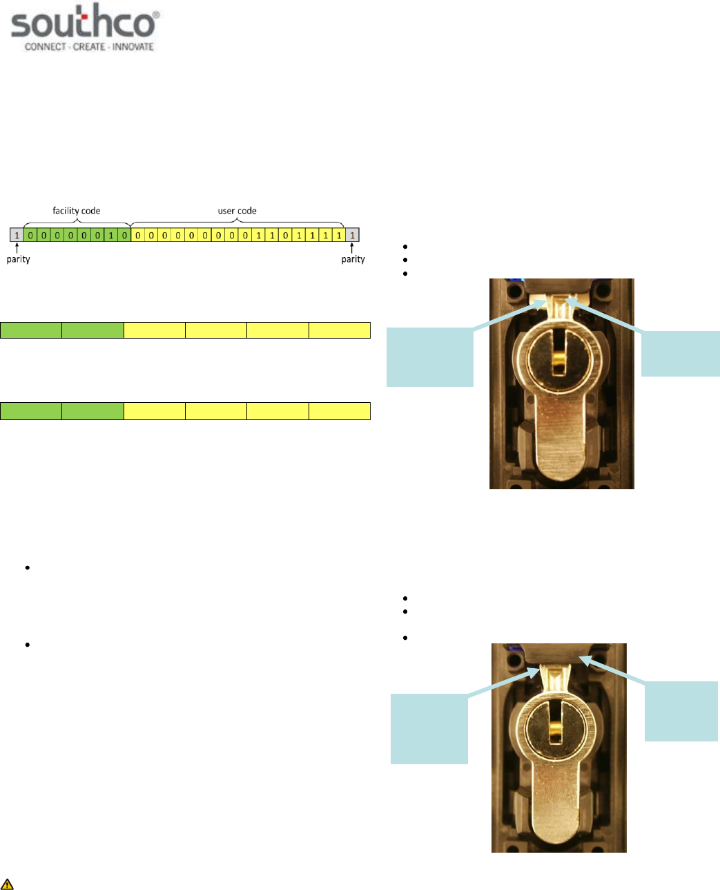
Secured
The latch is securely closed, prohibiting access.
The Status LED will be solid blue.
The electronic lock status output is at its open collector state.
The mechanical lock status output is at its open collector state.
“Secured” State
Electronically Released
The electronic lock slide is in the unlocked position and the handle can be
pulled open.
The Status LED will alternate flashing blue/magenta.
The electronic lock status output is 0V while the lock slide is in
the unlocked position.
The mechanical lock status output is at its open collector state.
“Electronically Released” State
electronic
lock slide in
unlocked
position
handle
secured in
housing, cam
in locked
position
electronic lock
slide in locked
position
handle secured
in housing, cam
in locked
position
H3-EM-69-100 Electronic Swinghandle
Operating Instructions
J-H3-EM-69-100-M_revB Page 4 of 4
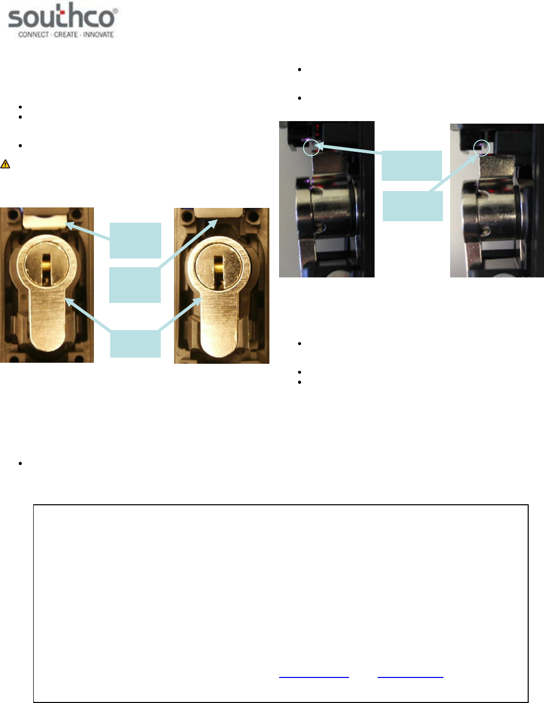
Mechanically Released
The latch is released by opening the handle or moving the cam from its
lock position.
The Status LED will flash blue.
The electronic lock status output will be at its open collector state
if the electronic lock slide is in the locked position. It will be 0V if
the lock slide is in the unlocked position.
The mechanical lock status output is 0V.
NOTE: The lock sensor is an optical device that senses the presence
of the lock pawl. Reflectivity of the lock pawl material can affect sensing.
Use only Southco-supplied locks.
“Mechanically Released” State
Handle not Fully Closed
This is an interim state and may occur while closing the handle when the
cam is not secured by the electronic lock slide. The latch is not fully
secured during this state.
The Status LED will alternate flashing blue/red if the cam is not
detected. It will flash blue/red/red if the cam is detected, but the
lock plate is not in the right position. This could be due to
mechanical failure or tampering.
The electronic lock status output is 0V if the lock slide is in the
unlocked position. It will be at its open collector state if it is in the
lock position.
The mechanical lock status output is 0V if the cam is not
detected. It will be at its open collector state if it is detected.
“Handle not Fully Closed” State
Electronic Lock Slide Error
The electronic lock slide does not respond to the command input signal.
The Status LED will flash magenta if the latch is secured. It will
alternate flashing red/magenta if the latch is mechanically
released.
The electronic lock status output is at its open collector state.
The mechanical lock status output will be at its open collector
state if the cam is in its lock position. It will be 0V if the
mechanical key is moved from its lock position.
POZIDRIV® is a registered trademark of the Phillips Screw Company
cam
detected by
latch
cam not
detected by
latch
electronic
lock slide in
unlocked
position
electronic
lock slide in
locked
position
lock plug in
unlocked
position
FCC Compliance Statement
This device complies with Part 15 of the FCC Rules. Operation is subject to the following two conditions:
1) This device may not cause harmful interference and
2) This device must accept any interference received, including interference that may cause undesired operation.
Industry Canada Compliance Statement
This Class B digital apparatus complies with Canadian ICES-003.
Cet appareil numérique de la classe B est conforme à la norme NMB-003 du Canada.
For technical support of this product contact: info@southco.com or visit: www.southco.com.