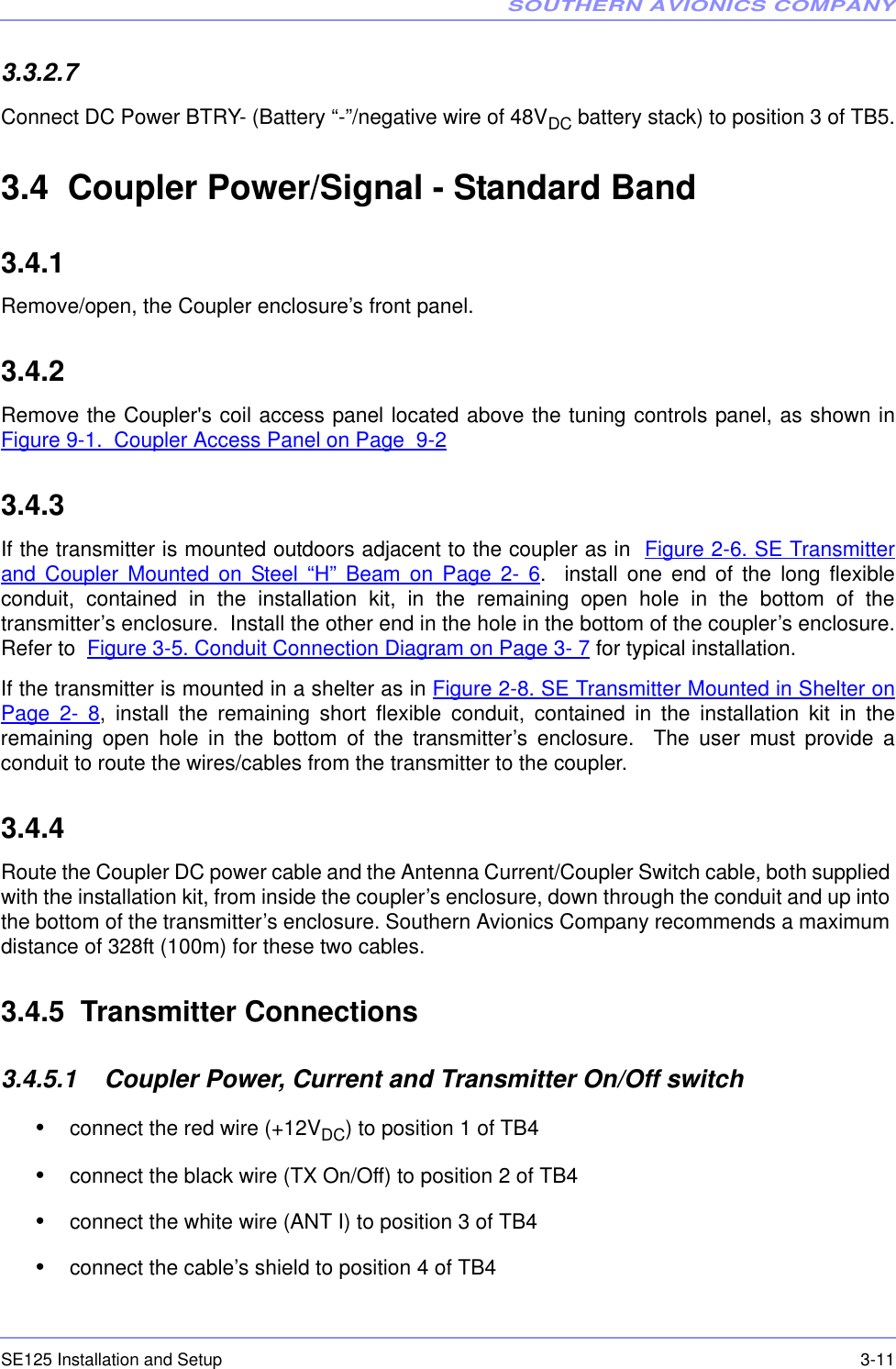
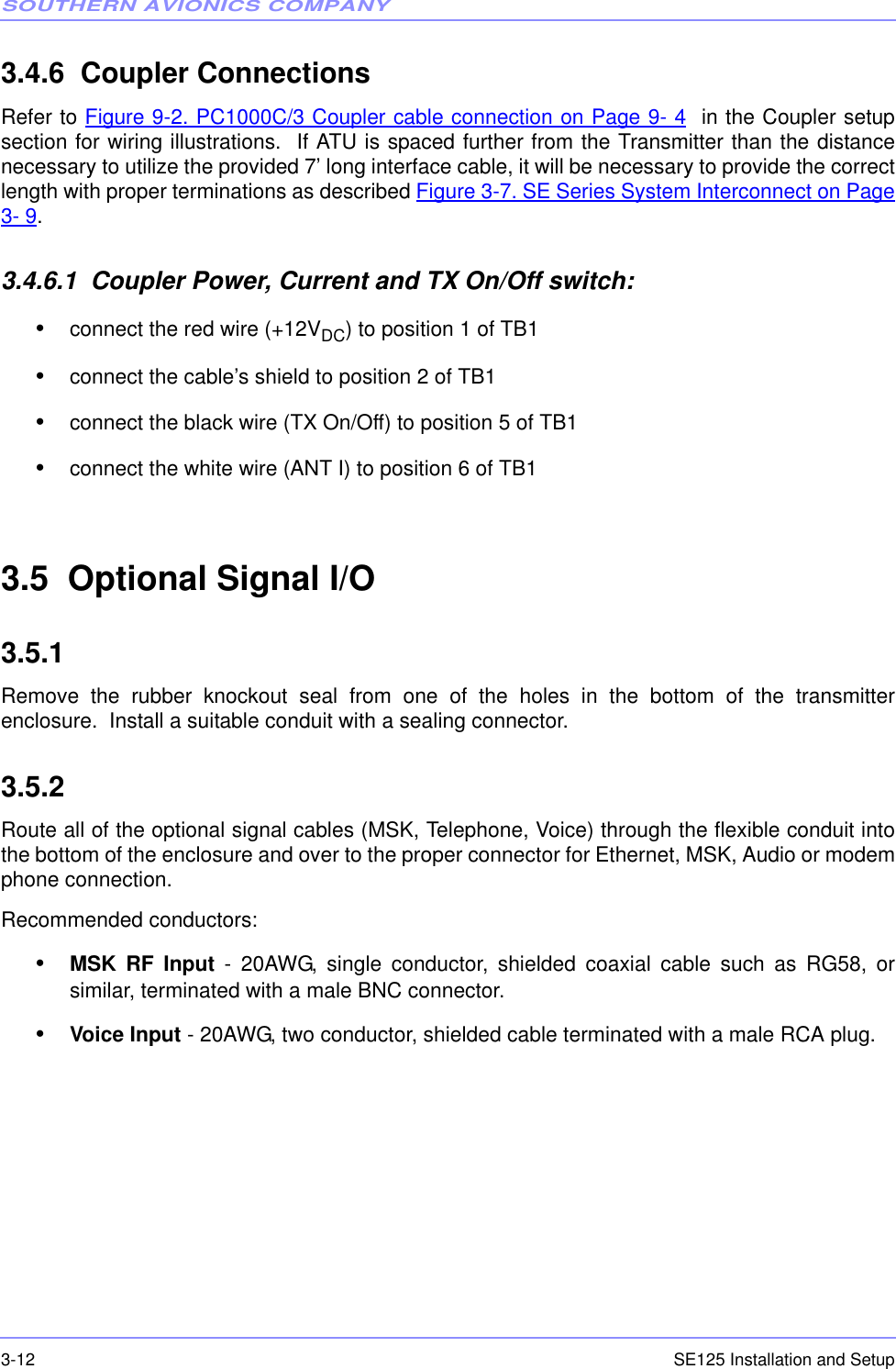
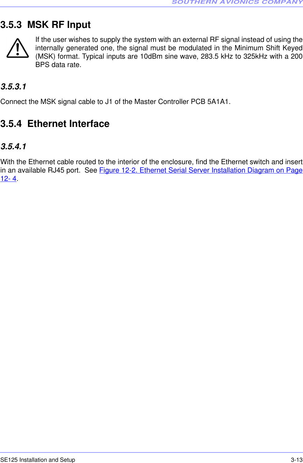
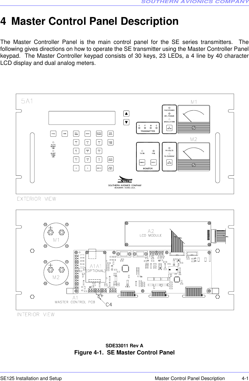
Southern Avionics SE125 Non-directional radio beacon User Manual SE 125 Installation and Setup
Southern Avionics Company Non-directional radio beacon SE 125 Installation and Setup
UserManual.wiki
>
Southern Avionics
>
SE125 User Manual
Users Manual
Navigation menu
Upload a User Manual
Namespaces
Wiki Guide
HTML
PDF
Info
Views
User Manual
Discussion / Help
Navigation

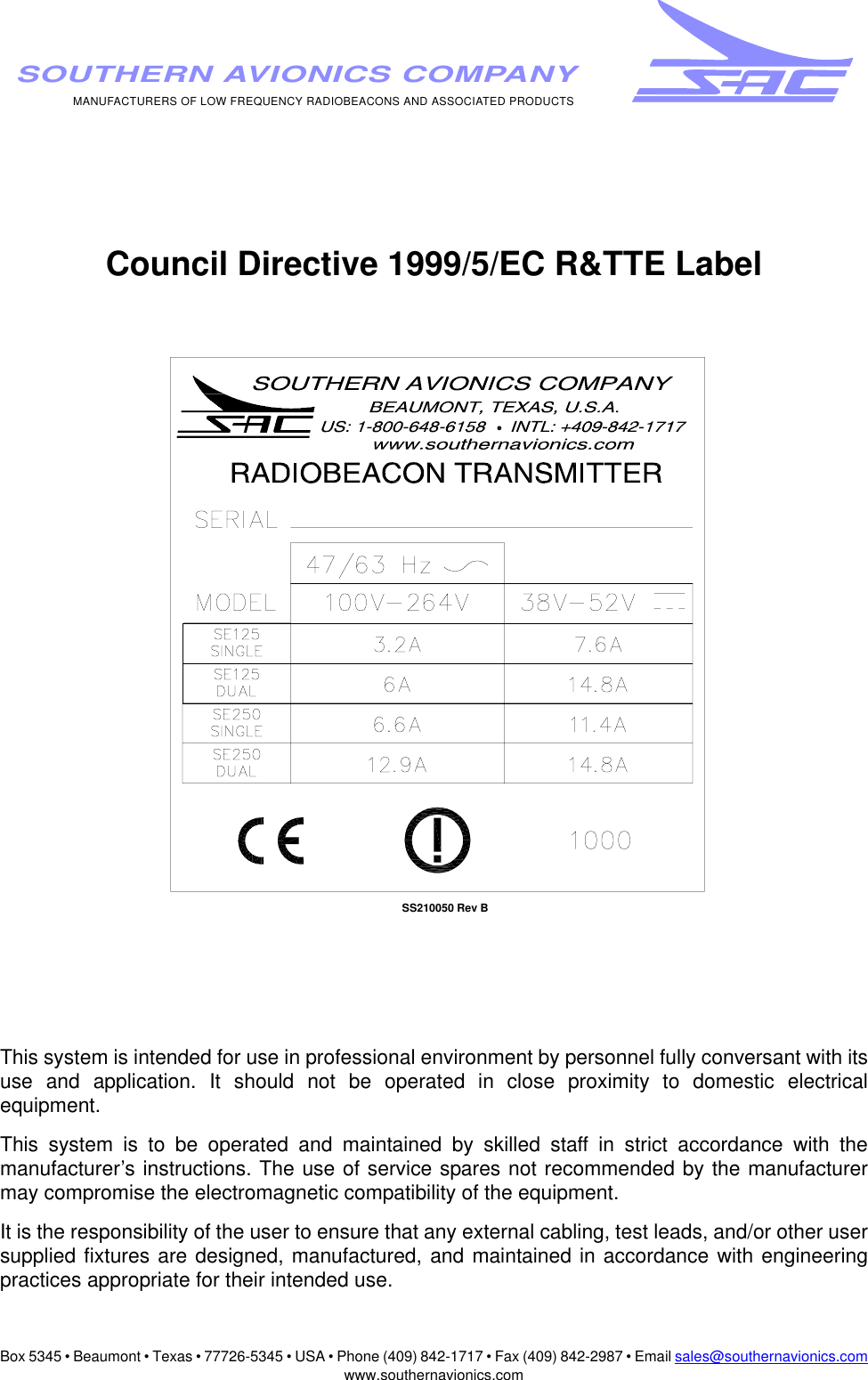
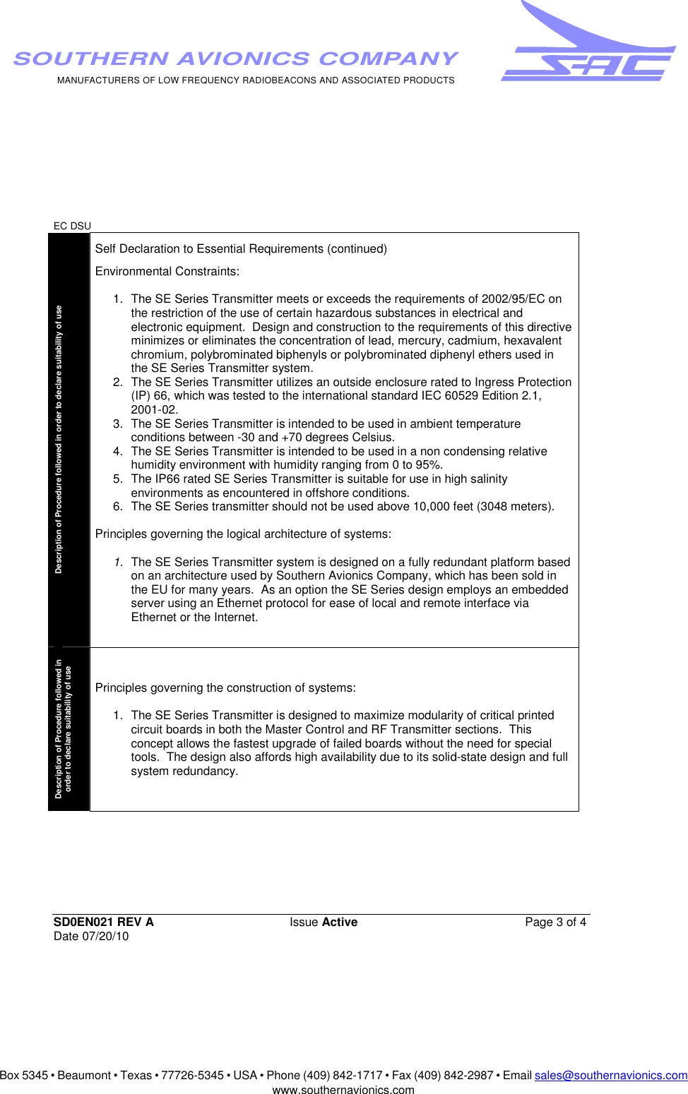


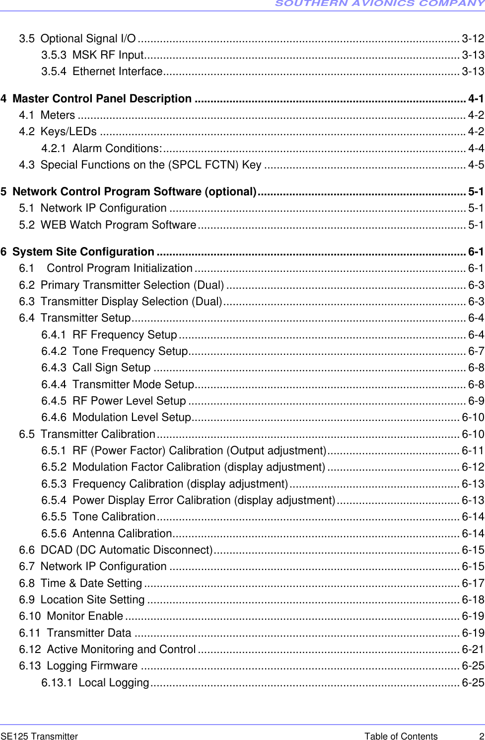
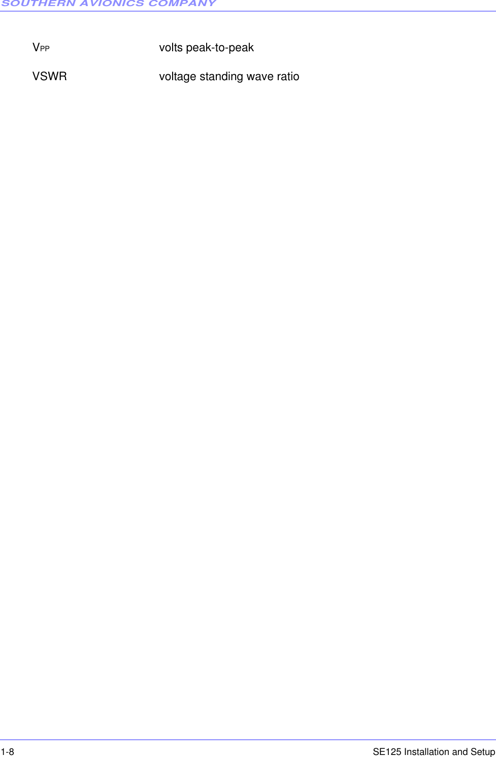

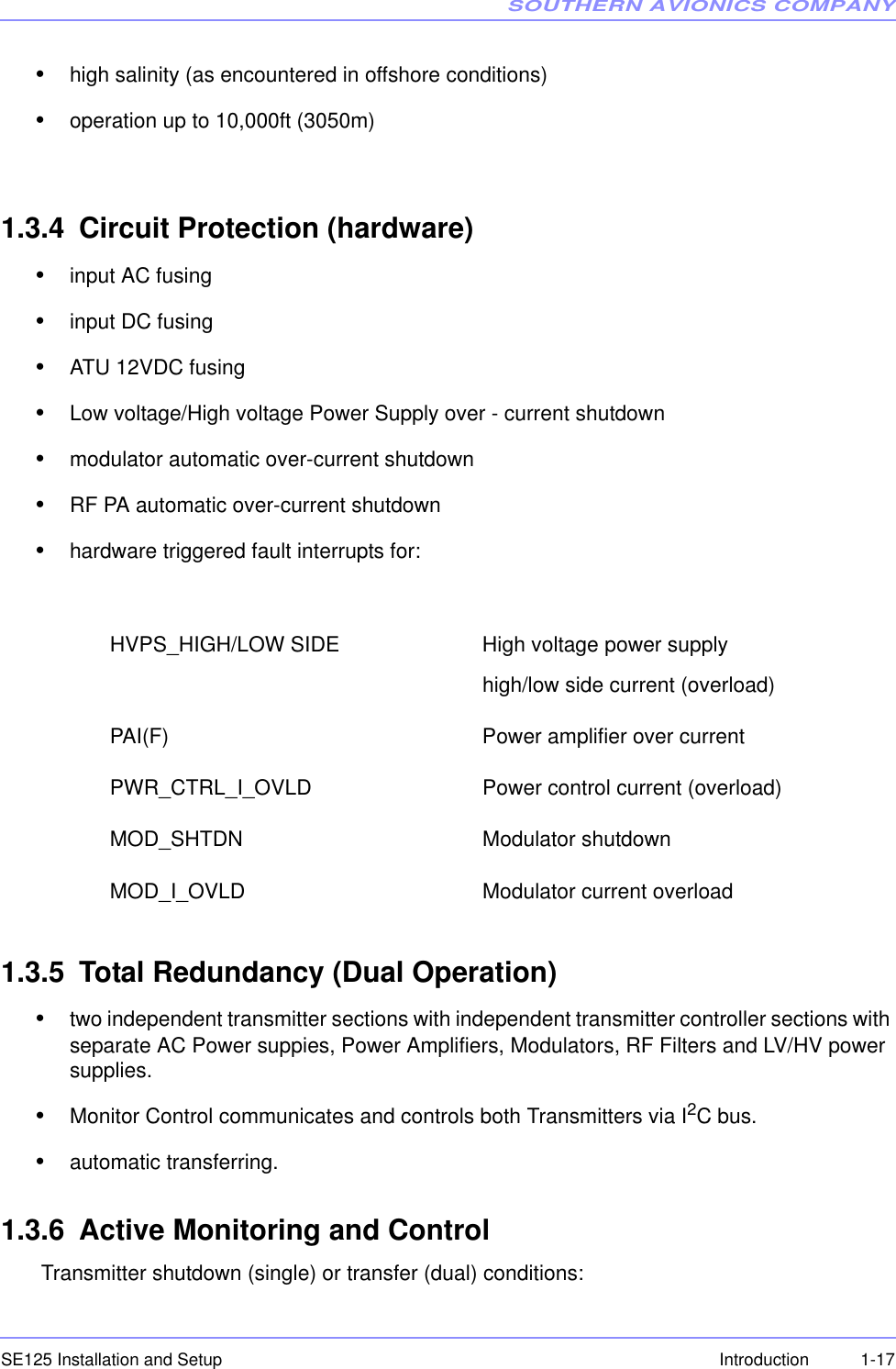


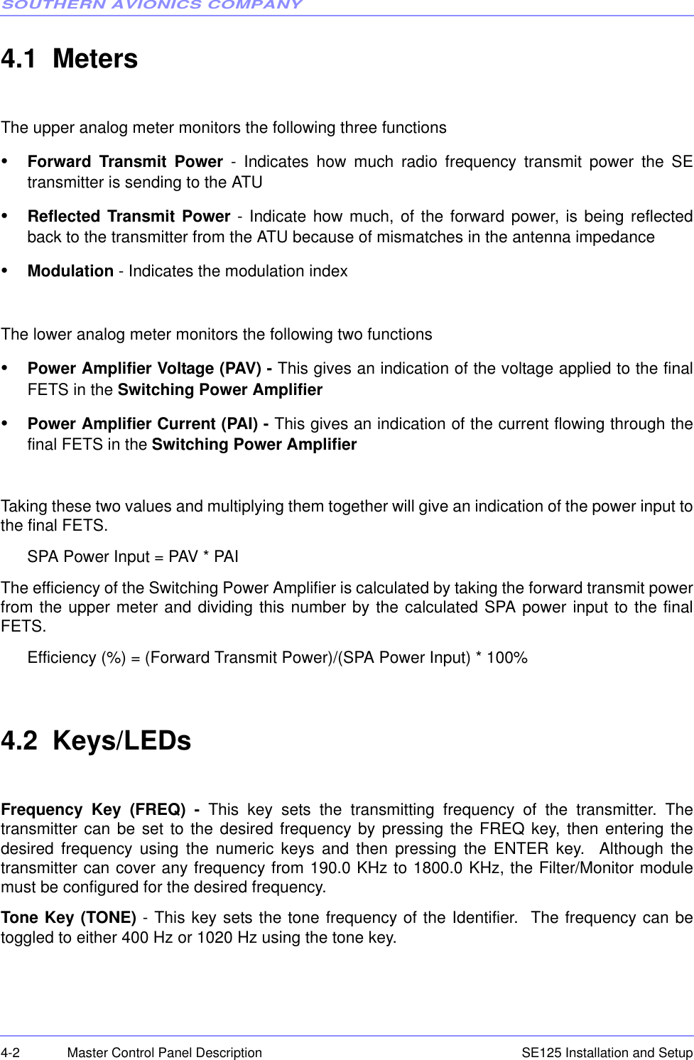
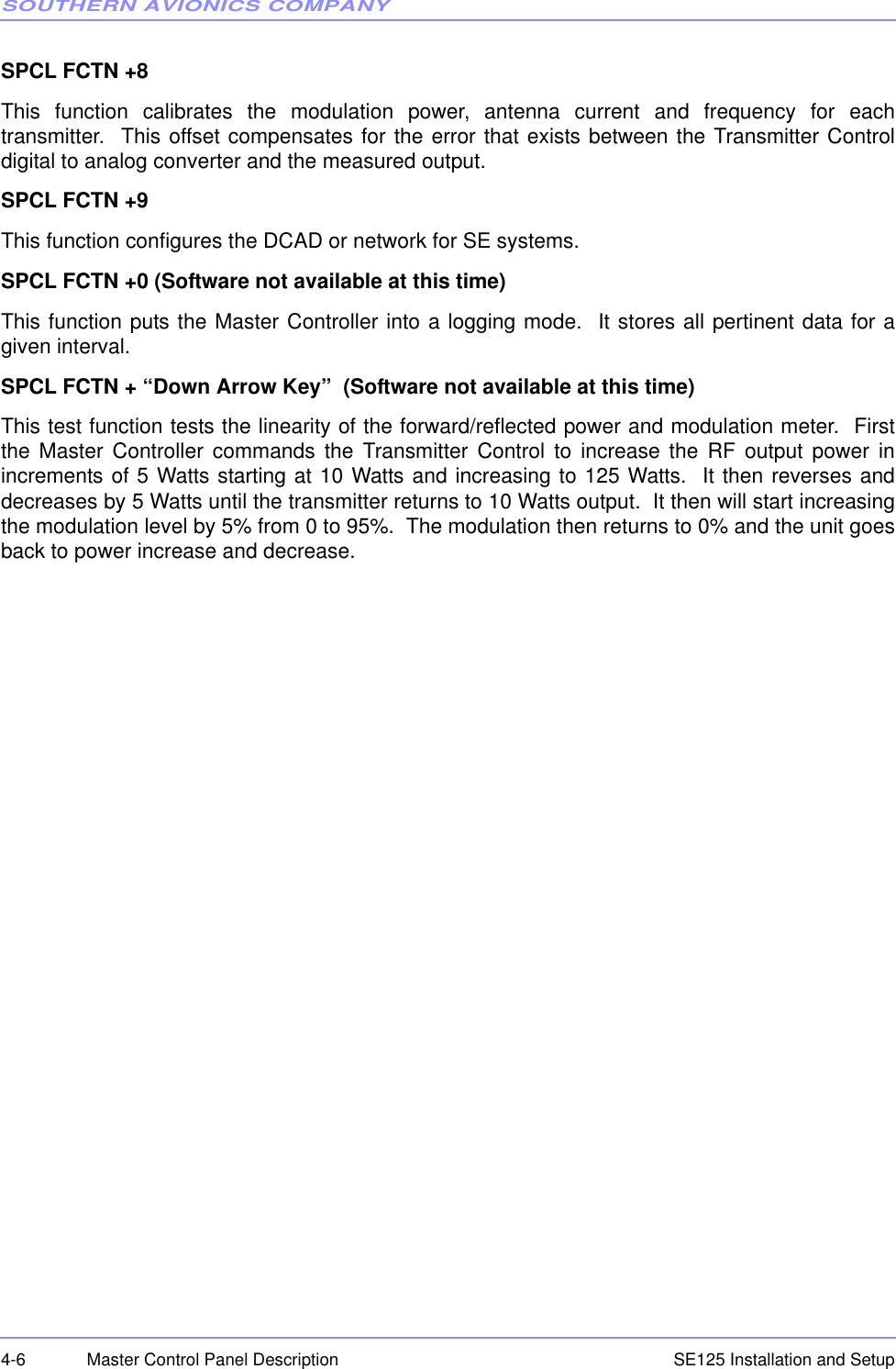

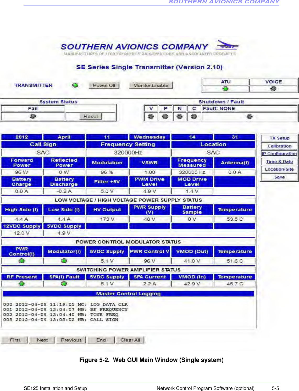

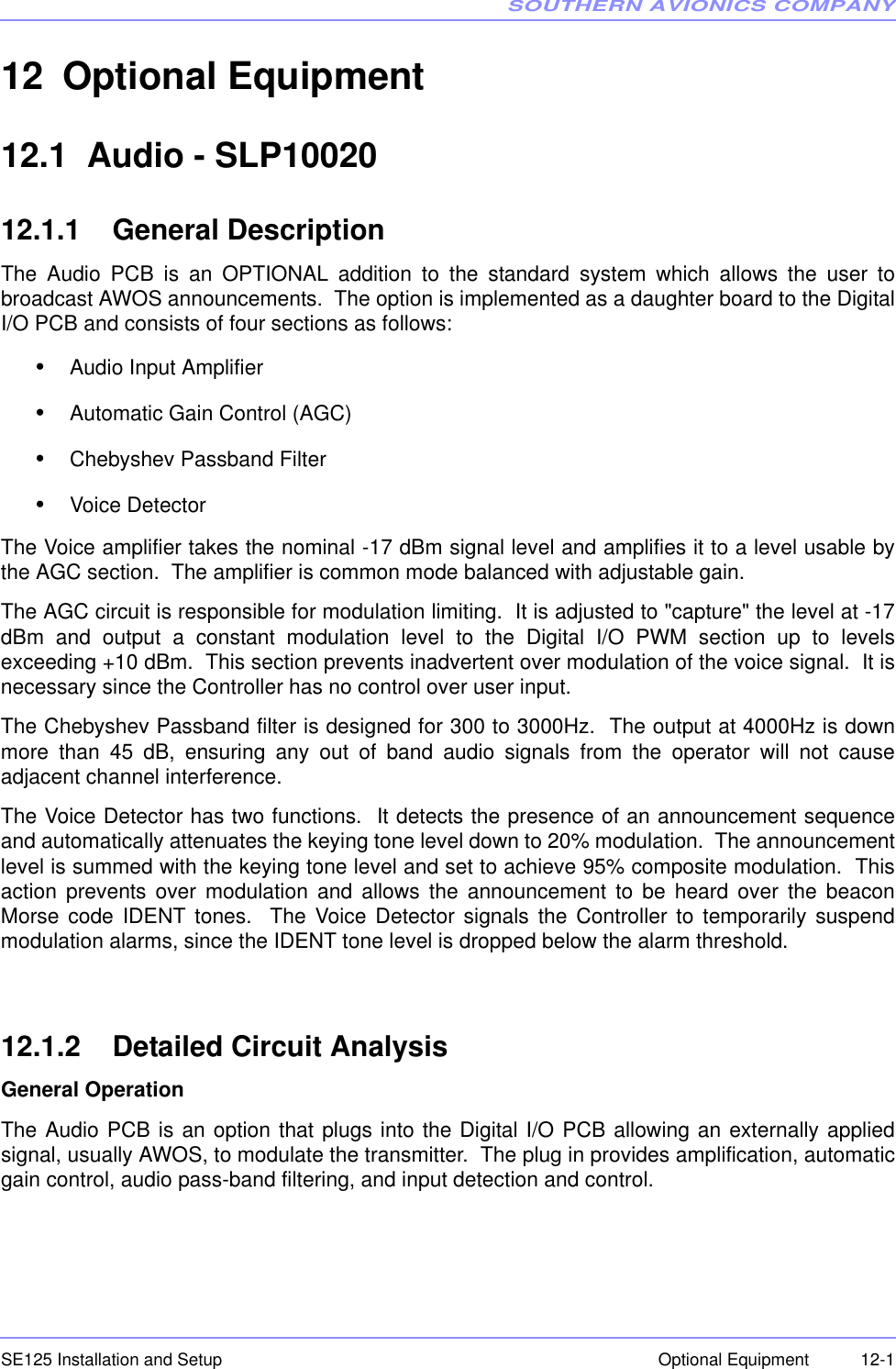
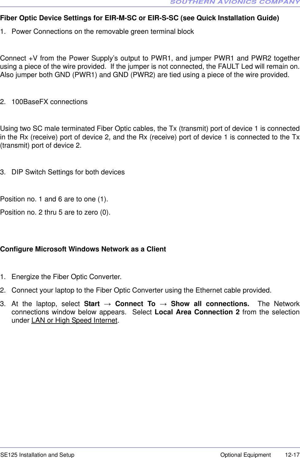
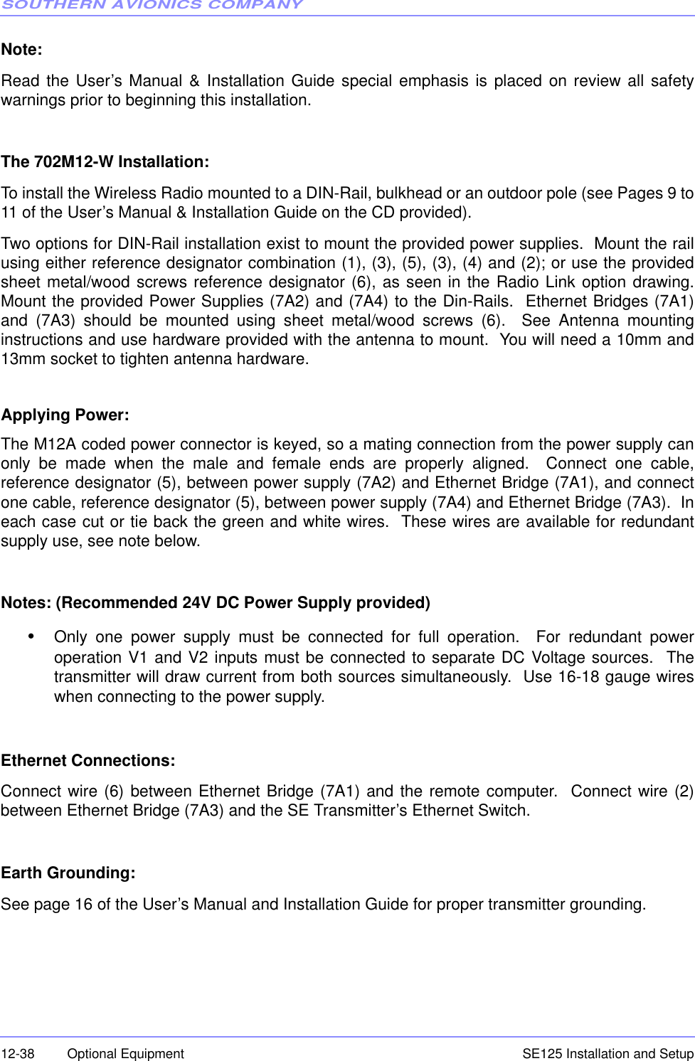
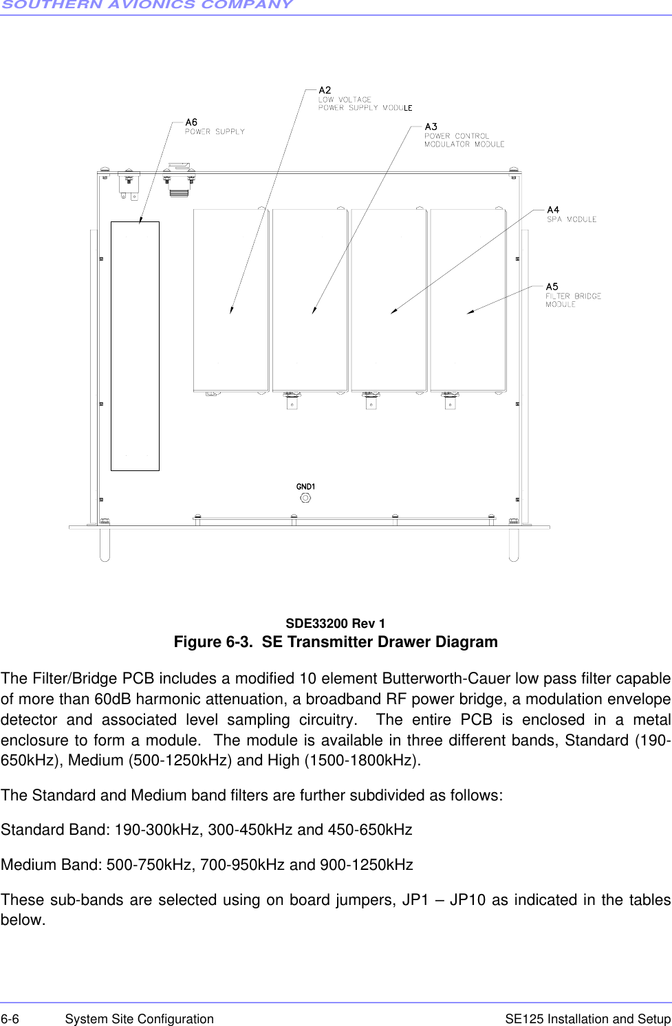
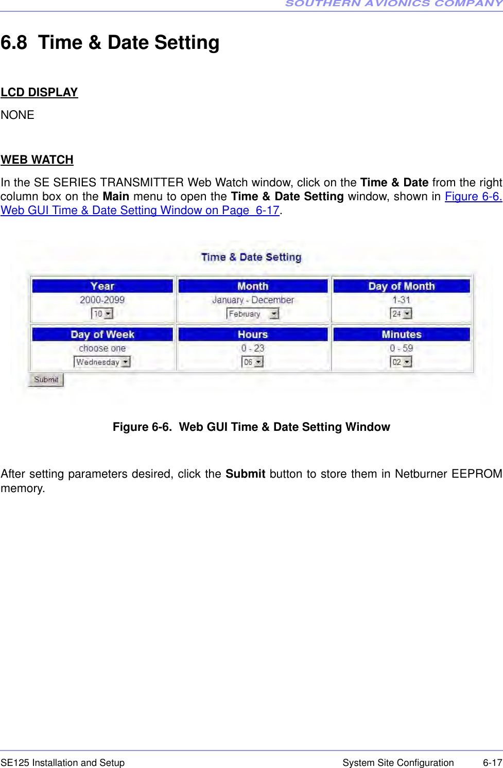
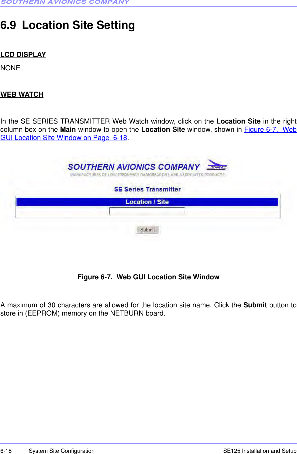
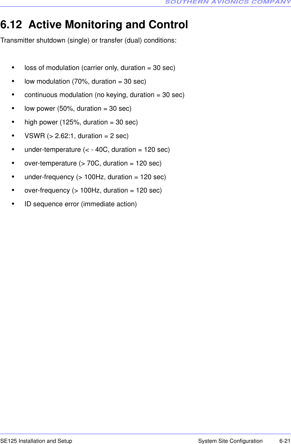
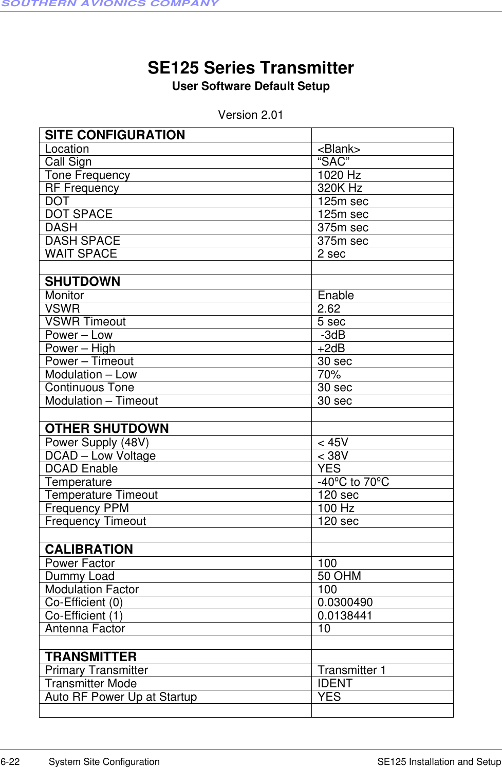
![SOUTHERN AVIONICS COMPANYSE125 Installation and Setup6-2 System Site ConfigurationOrNOTE: Normally the ATU switch should be in the ON position. If the ATU switch is OFF, the SEsystem will show the ATU message (shown below) automatically on the main menu.The dual or single transmitter system will be defined in the upper left hand side of the screenfollowing “SE SERIES” (see Main Menu above). If any faults exist, they will be shown in theupper right hand side of the screen. Additional display screens are chosen by using the UP andDOWN keys to more menus which show the overall / transmitter data.The dual system also utilizes the following four keys:•LCD DATA - to choose TX1 or TX2 display and control.•TEST MODE - to allow both transmitters to operate simutaniously for testing purposes. •MAIN TX - to allow primary/secondary assignment monitor.•MONITOR (system status: PRI, SEC, FAIL) - to enable or disable monitoring usually fortesting purposes. Use the UP key to cancel or go the previous menu anytime. SE SERIES [DUAL] Fault: NONE RF Frequency Setting ......... 320000 Hz Tone Frequency Setting ....... 1020 Hz Call Sign: SAC TX Mode:IDENT SE SERIES [SINGLE] Fault: NONE RF Frequency Setting ......... 320000 Hz Tone Frequency Setting ....... 1020 Hz Call Sign: SAC TX Mode:IDENT ********* ATU SWITCH IS OFF ********** Please check hardware.](https://usermanual.wiki/Southern-Avionics/SE125/User-Guide-1785097-Page-90.png)
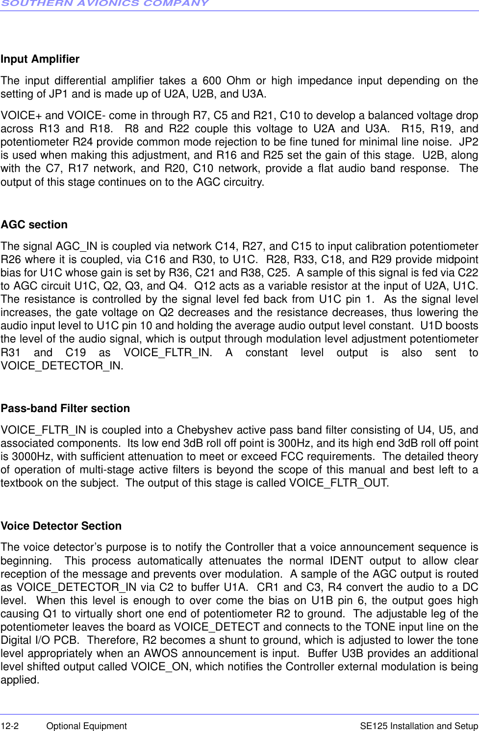
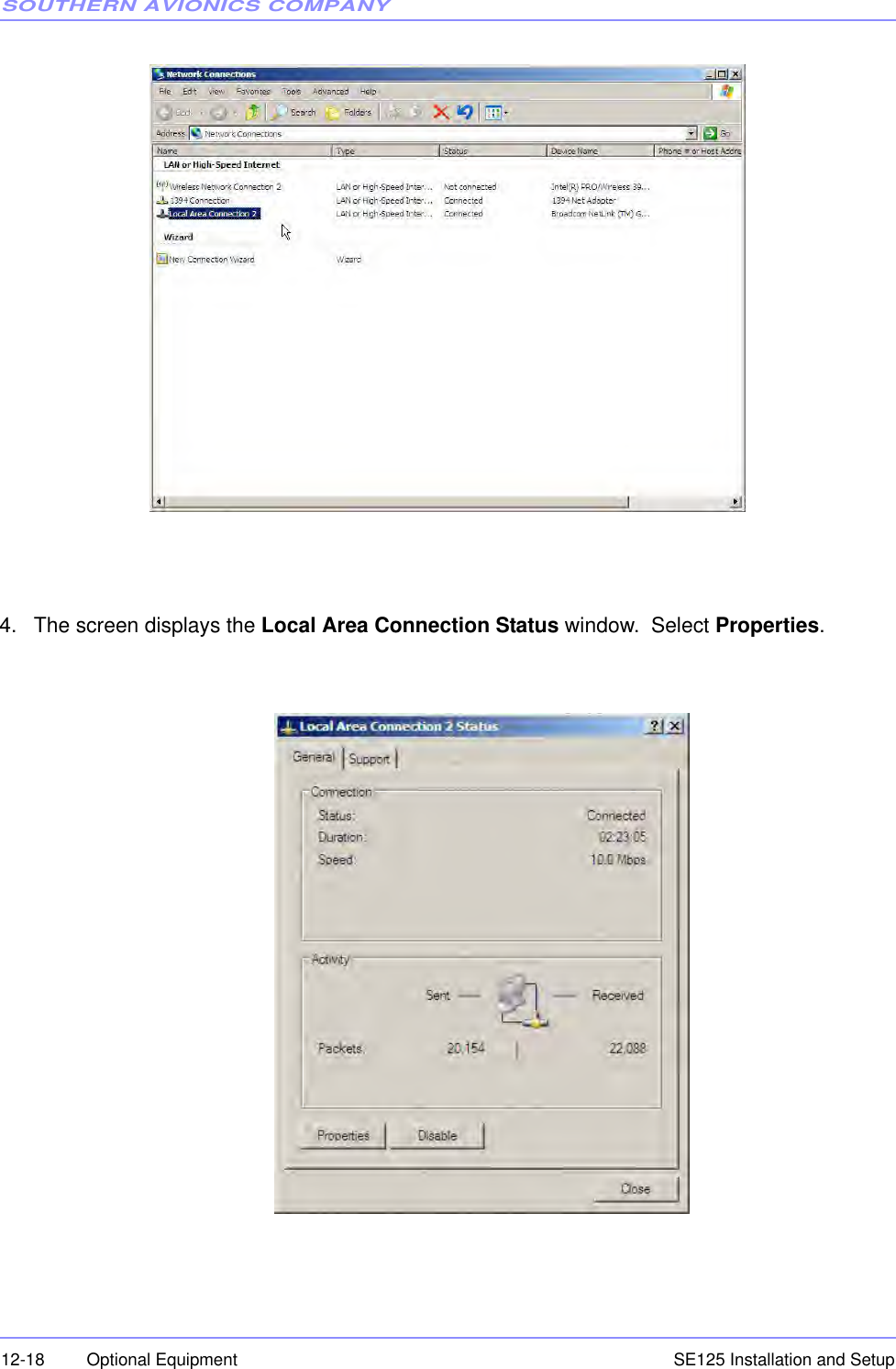
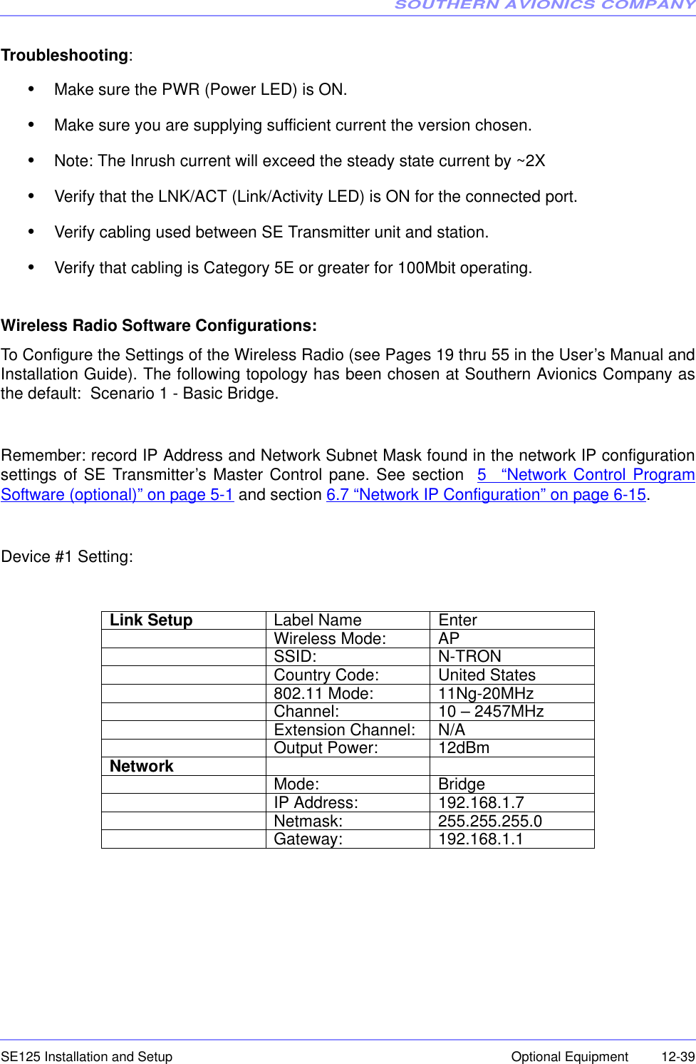
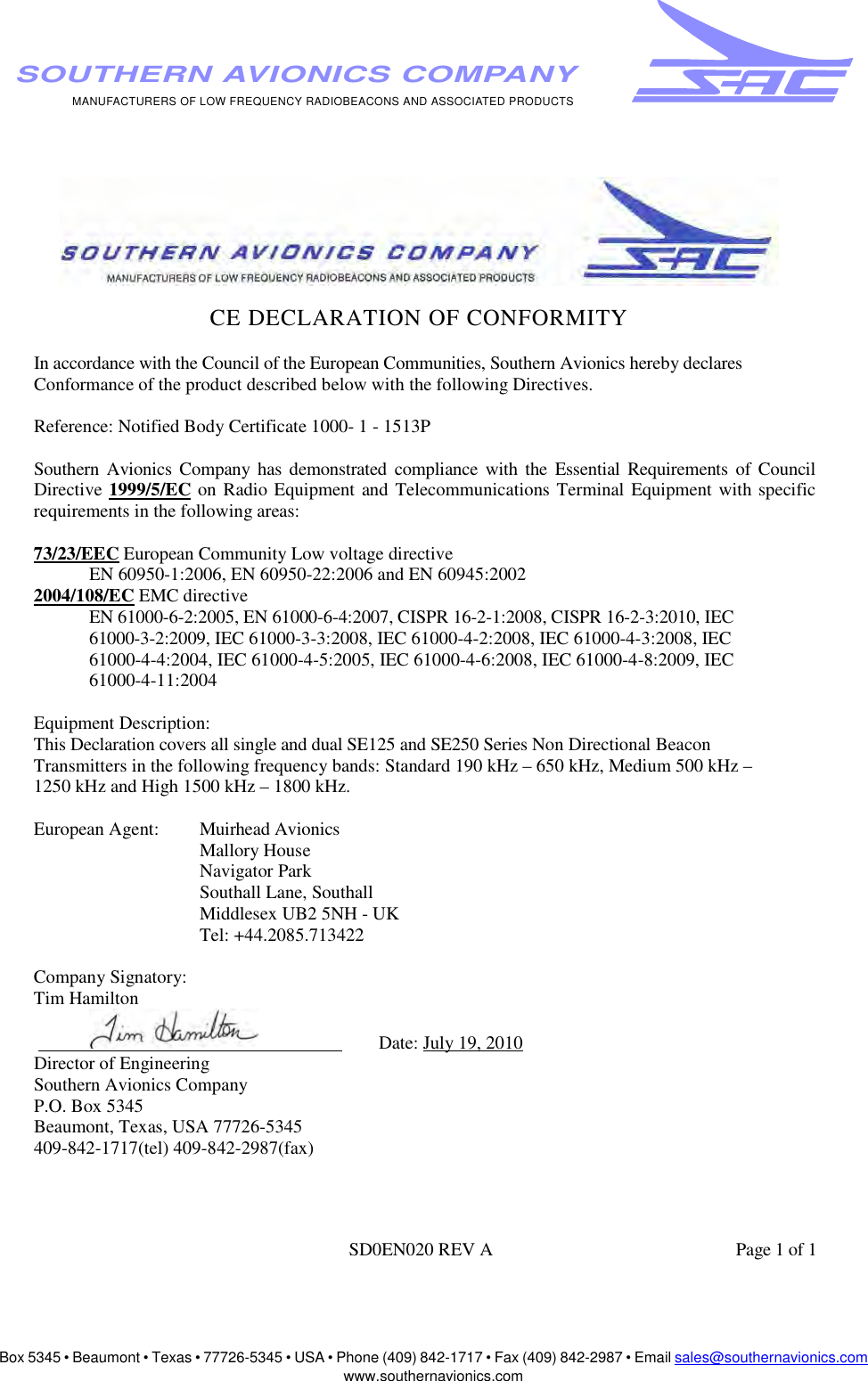
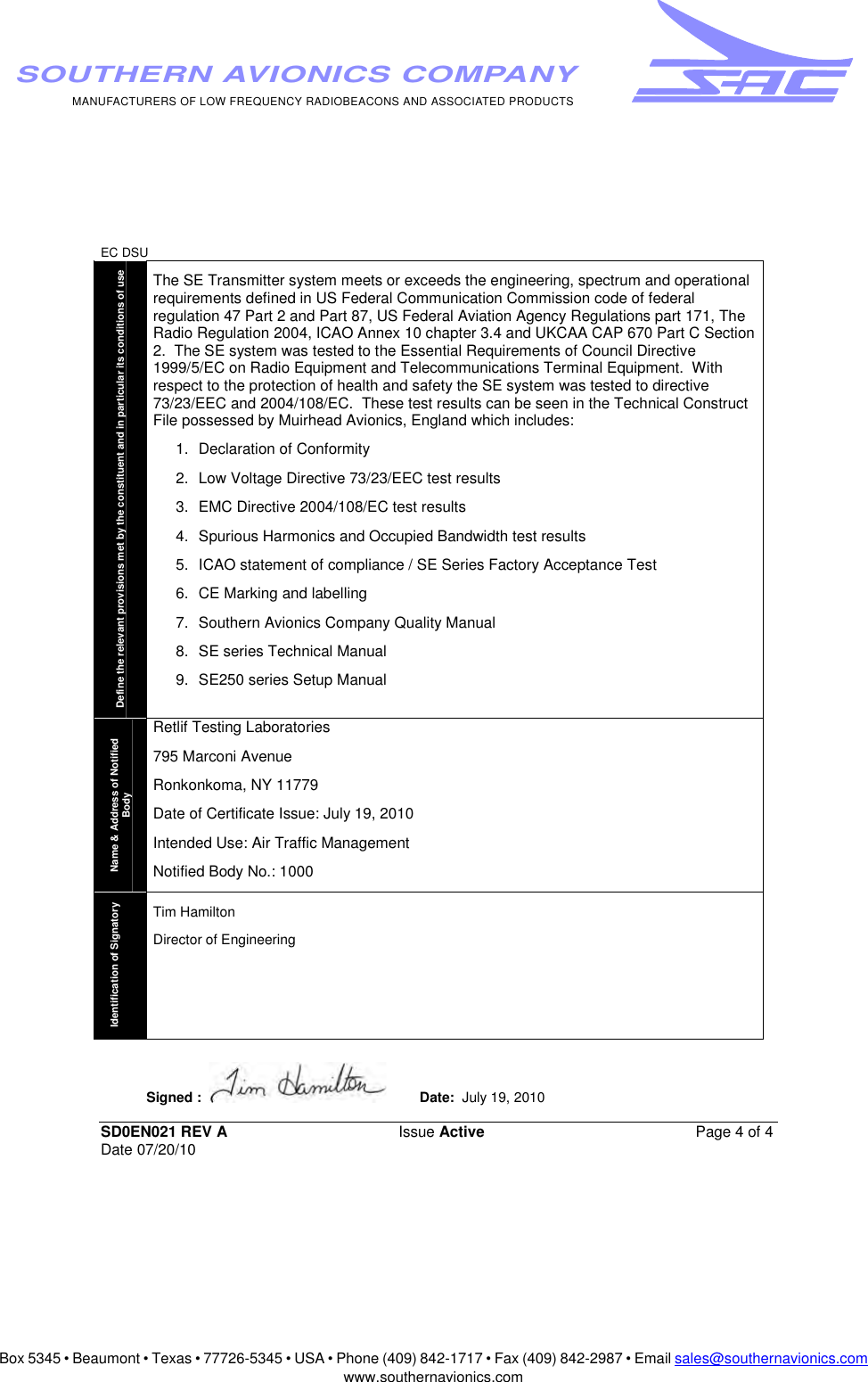
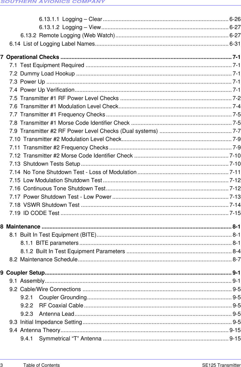
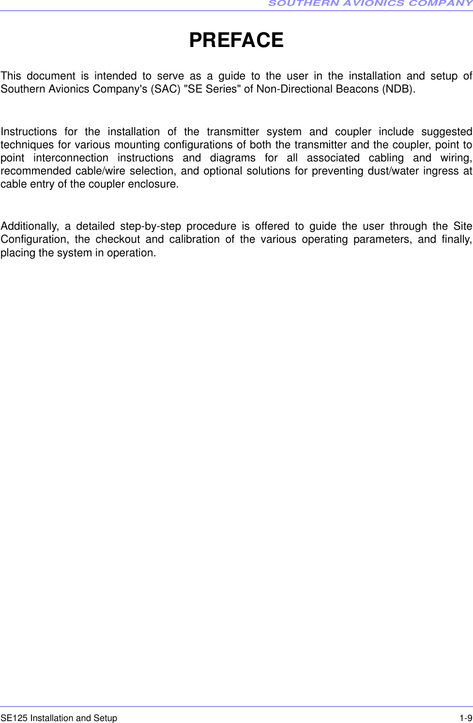
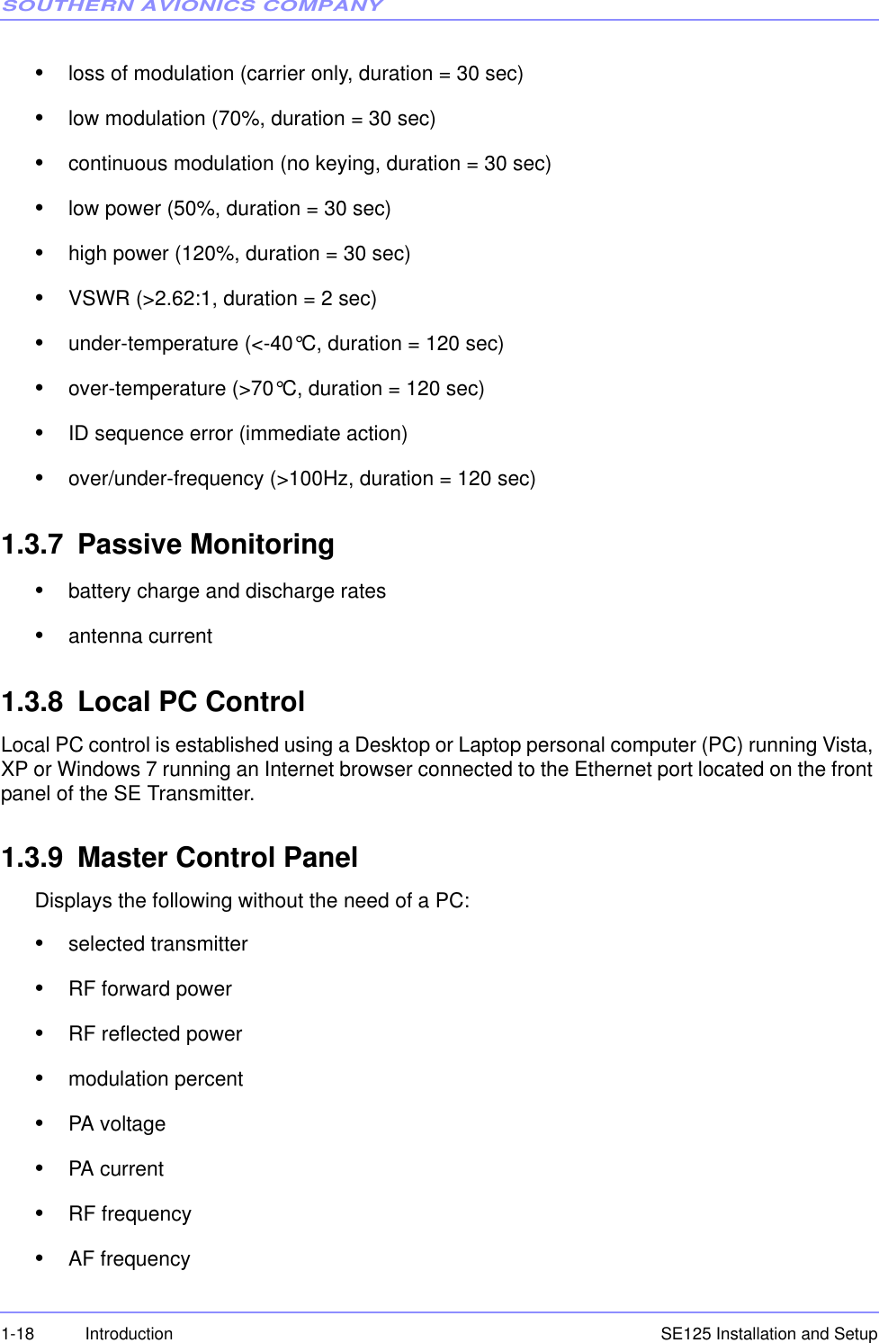
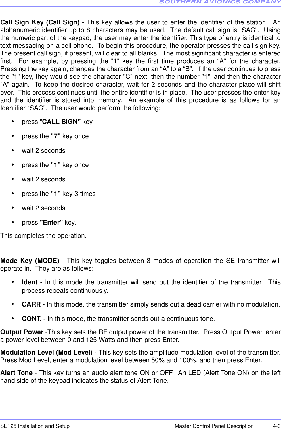
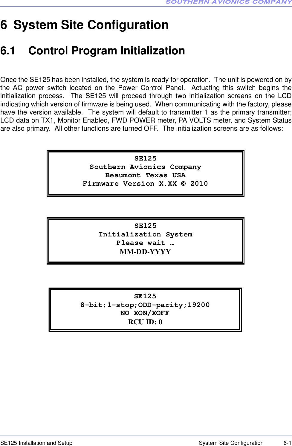
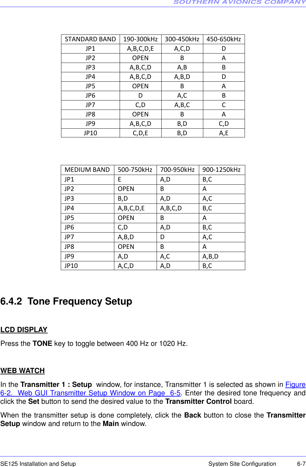
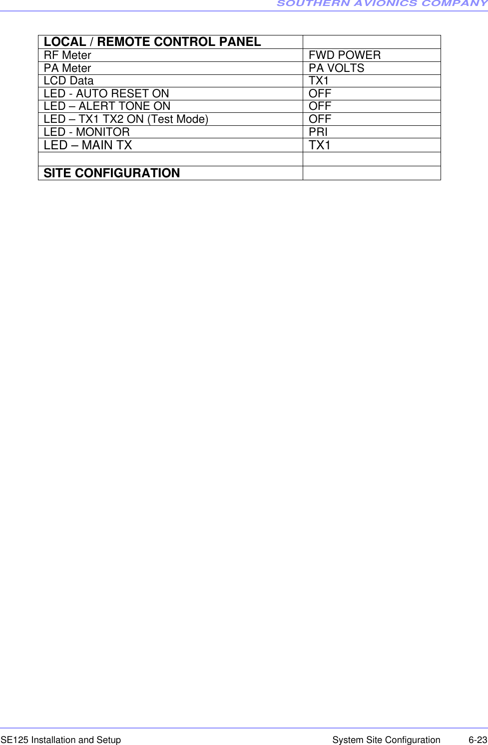
![SOUTHERN AVIONICS COMPANYSE125 Installation and Setup6-4 System Site ConfigurationWEB WATCHClick on the Toggle button on the Main menu to toggle between TX1 and TX2 for display andcontrol of the Transmitter.6.4 Transmitter SetupThis section details how to set RF frequency, tone frequency, call sign, power and modulation asdictated by the site license.6.4.1 RF Frequency SetupLCD DISPLAYPress the FREQ key to open the RF FREQUENCY ENTRY menu as shown below.Repeat pressing the FREQ key to clear then enter the desired frequency in the field. When the ENTER key is pressed, the RF power level will be set to 0 Watts immediately to protectthe transmitter.Press SPCL FCTN then 1 to store any changes.WEB WATCHIn the SE SERIES TRANSMITTER Web Watch window, click on Setup in the right column boxon the Main window to open the Transmitter 1/2 : Setup window shown in Figure 6-2. WebGUI Transmitter Setup Window on Page 6-5. RF FREQUENCY ENTRY FREQ should be between 190K and 1800K Hz Enter RF Frequency: [ 320000] Hz](https://usermanual.wiki/Southern-Avionics/SE125/User-Guide-1785097-Page-92.png)
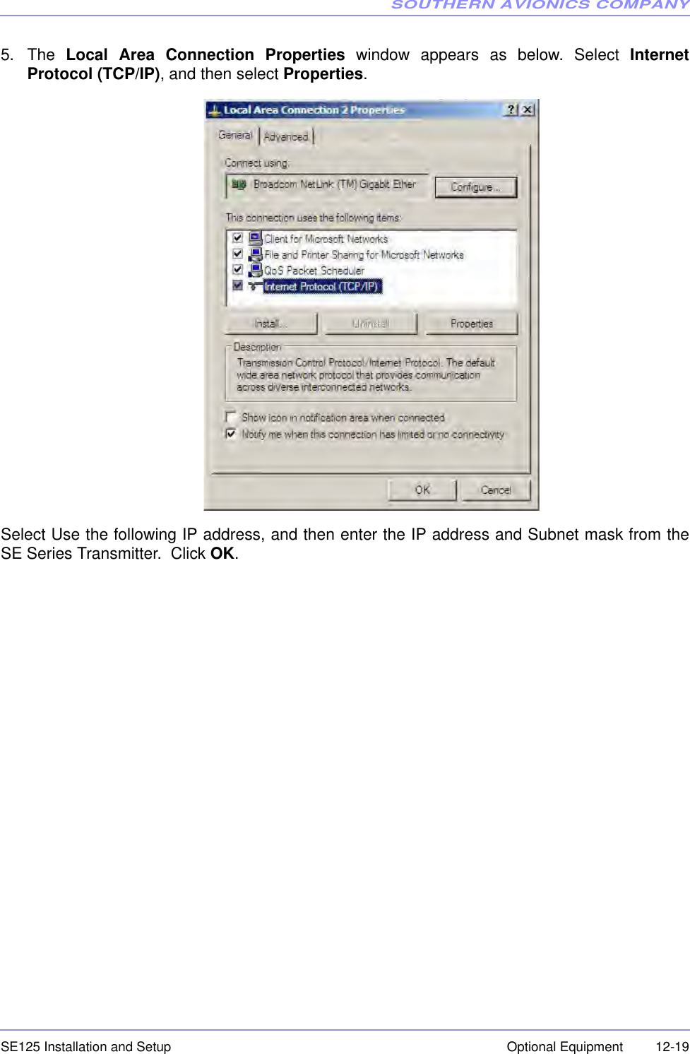
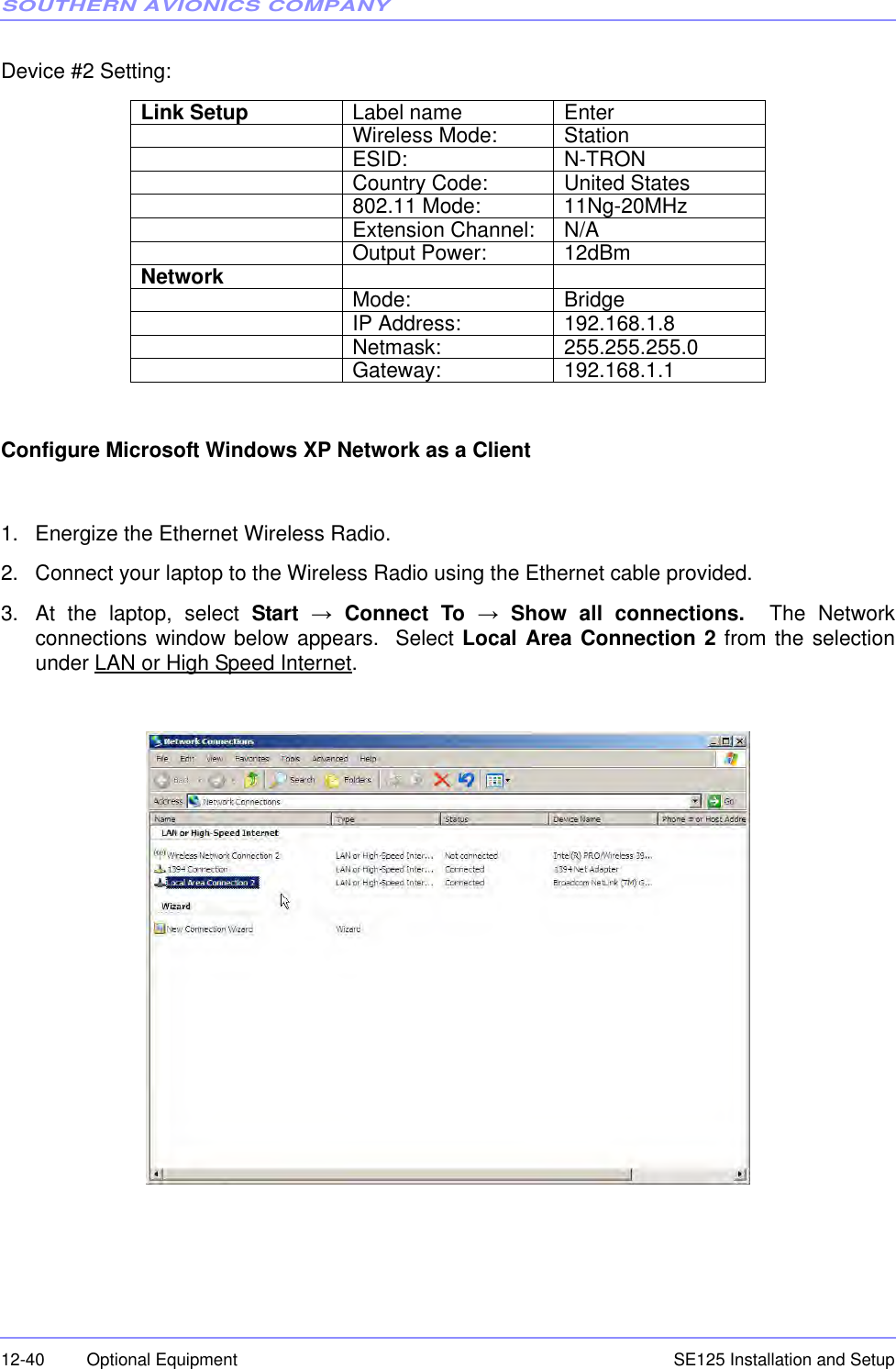
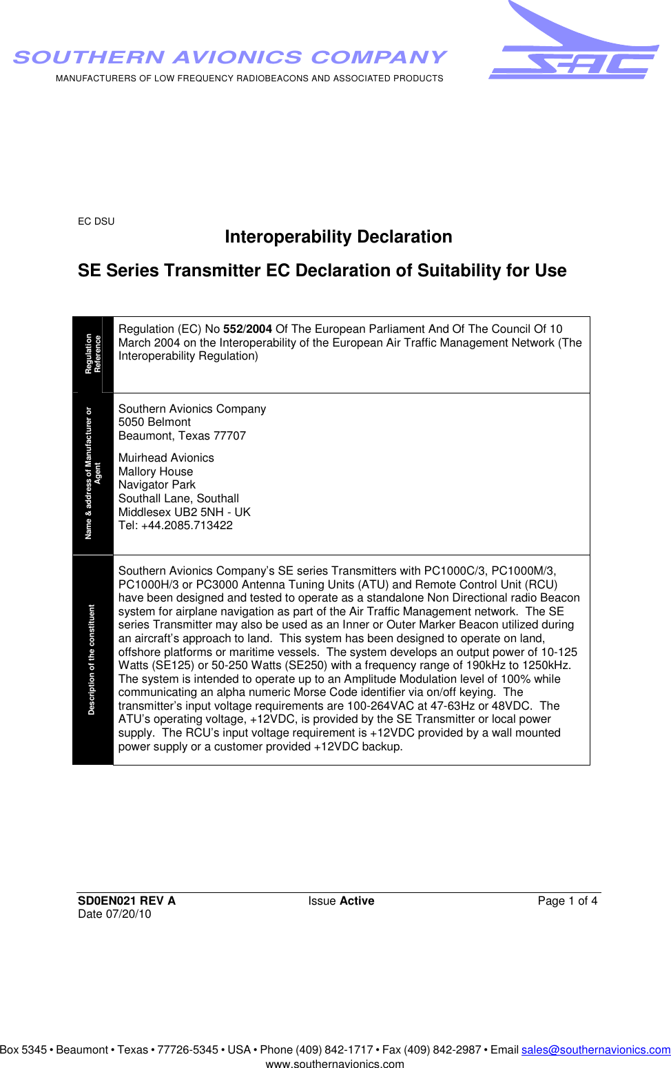
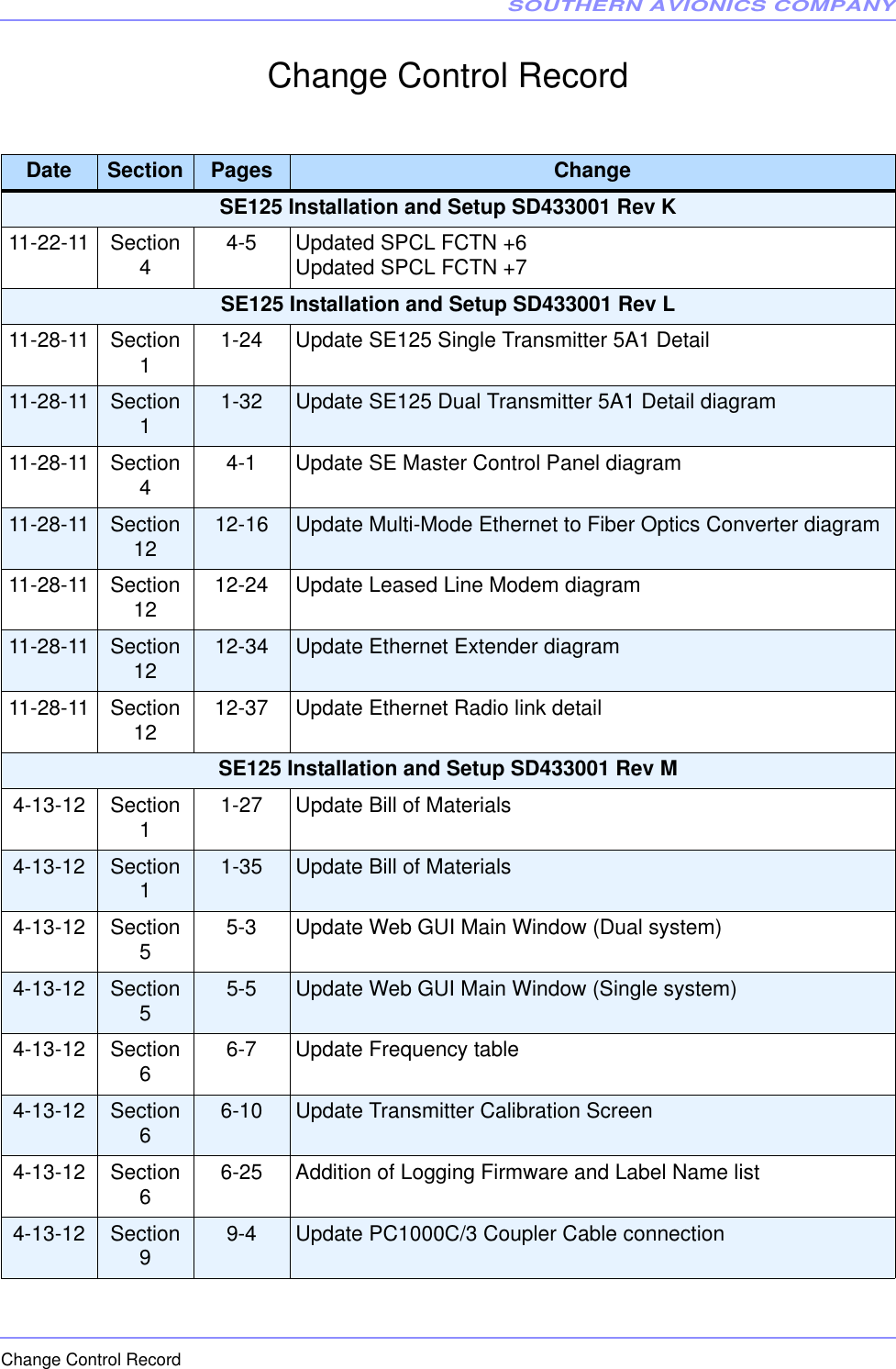
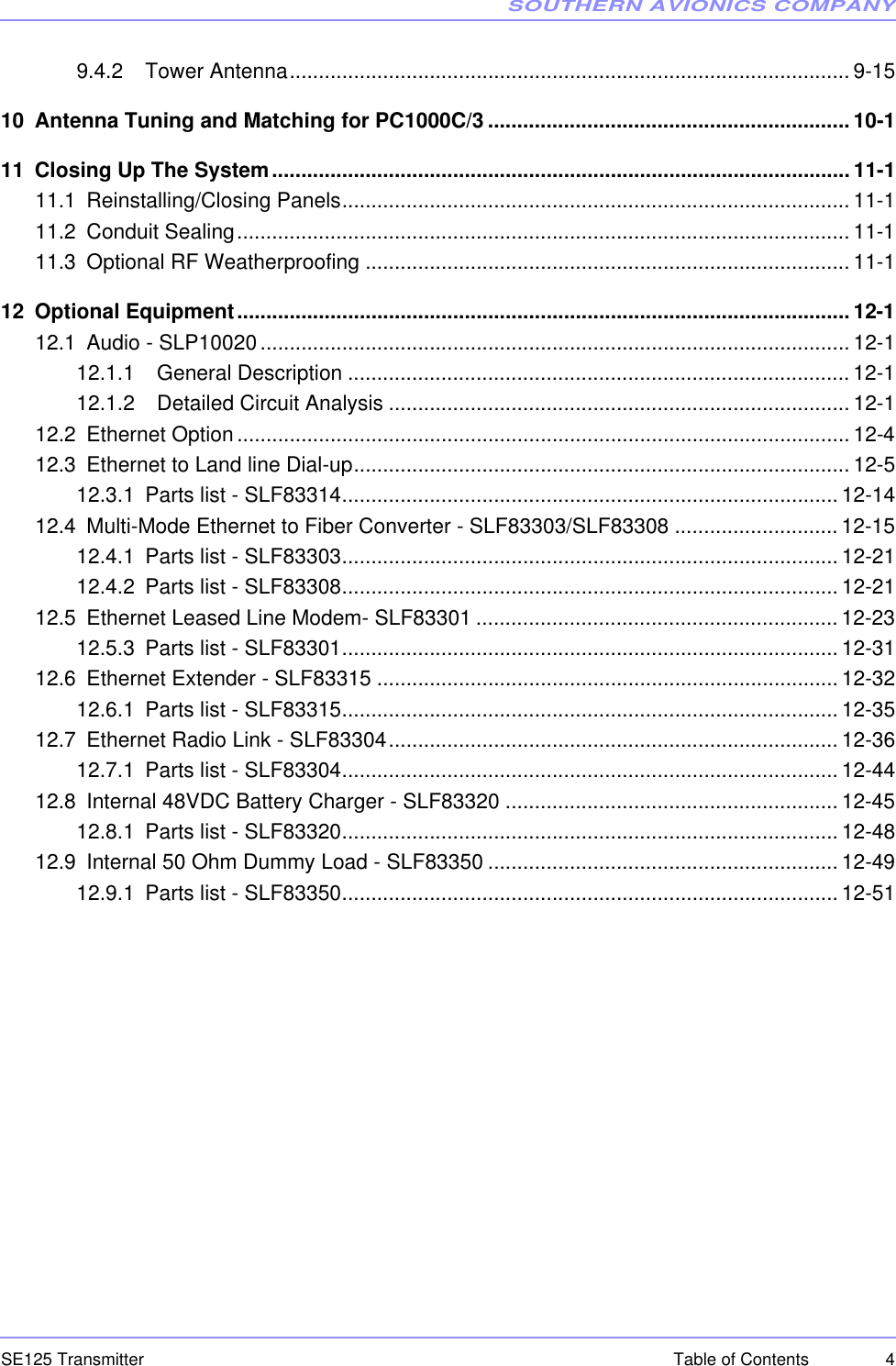
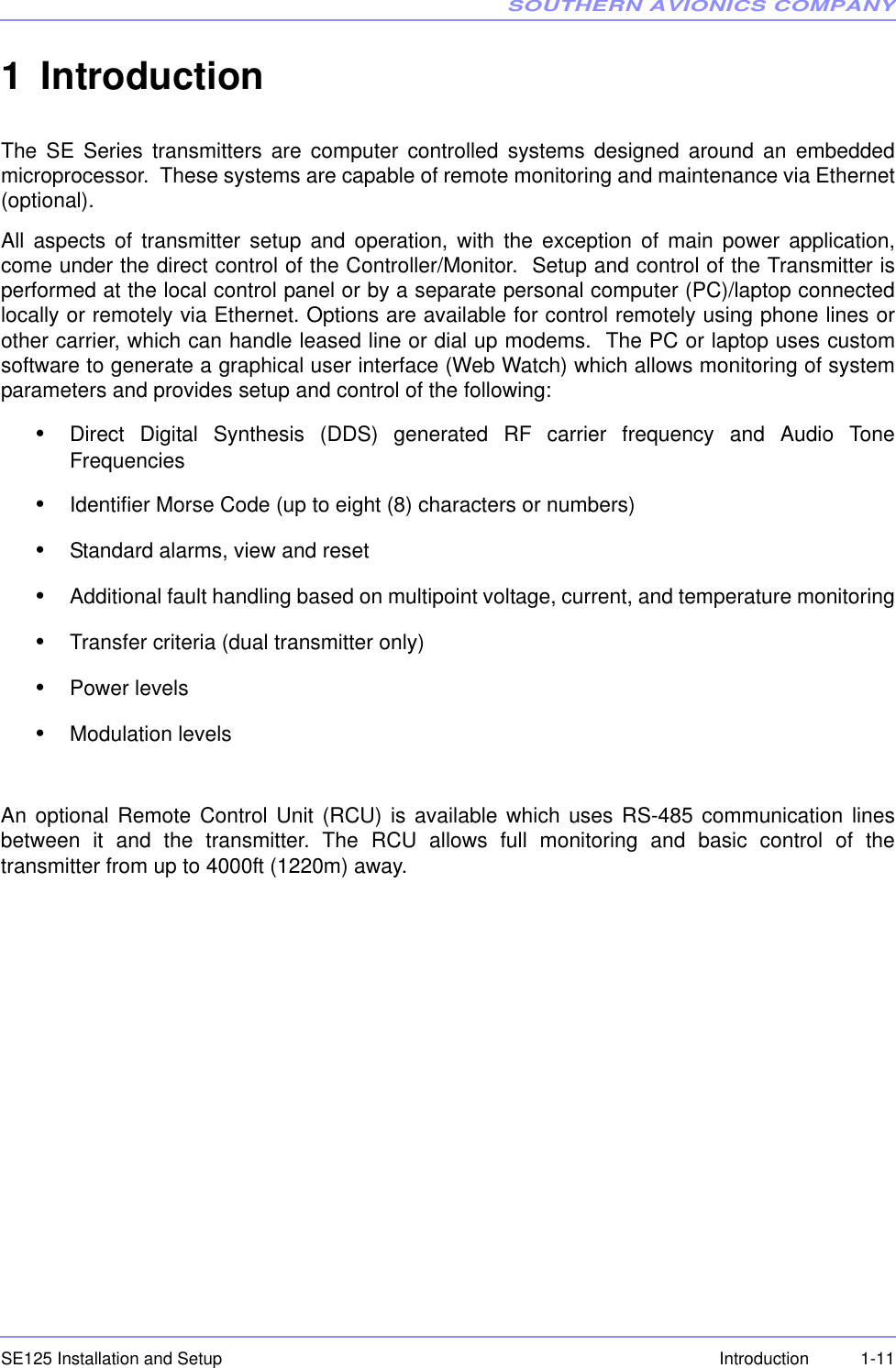
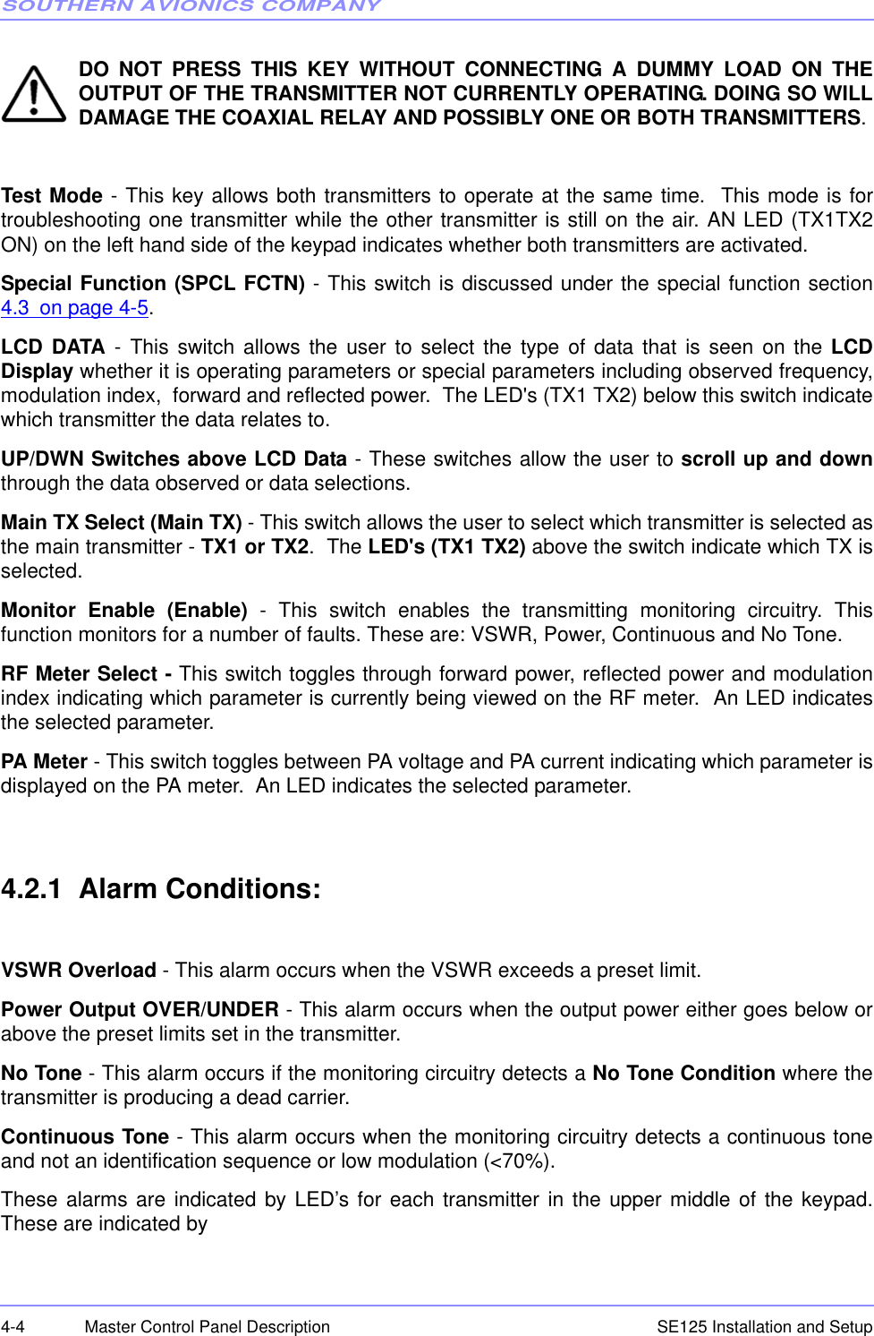
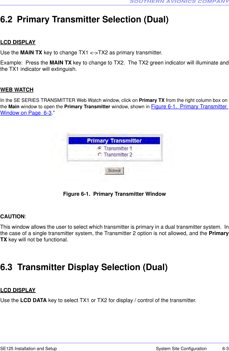
![SOUTHERN AVIONICS COMPANYSE125 Installation and Setup 6-9System Site ConfigurationWEB WATCHSelect the desired mode from the pulldown menu and click on Set to send the mode toTransmitter Control board memory.6.4.5 RF Power Level SetupCAUTION: Ensure that the RF Frequency setting corresponds to that of the Filter PCB.LCD DISPLAYPress the OUTPUT POWER key to open the RF POWER SETTING menu, as shown belowRepeat pressing the OUTPUT POWER key to clear the RF power level in the field box. Enter thedesired power using the keypad.When the ENTER key is pressed, the Master Control will send the desired level to theTransmitter Control board memory.WEB WATCHOperates similarly to the LCD DISPLAY above. SE SERIES [DUAL] Fault: NONE RF Frequency Setting ......... 320000 Hz Tone Frequency Setting ....... 400 Hz Call Sign: SAC TX Mode: CARR ---------- RF POWER SETTING ---------- POWER should be 0 through and 125. Enter RF Power Level: [100] Watts](https://usermanual.wiki/Southern-Avionics/SE125/User-Guide-1785097-Page-97.png)
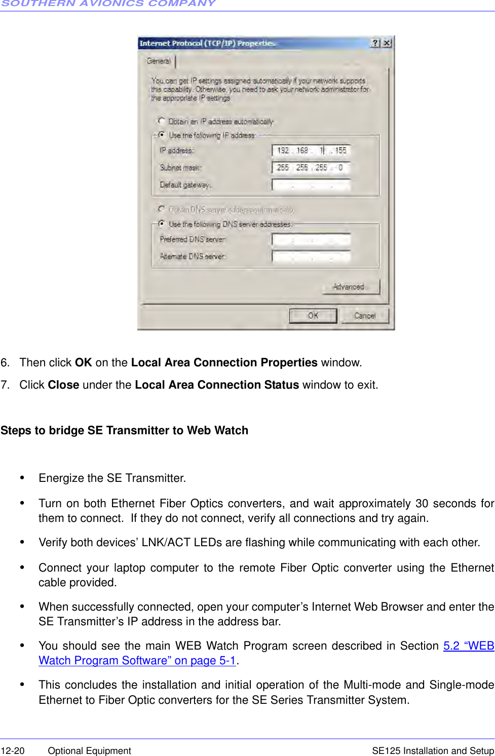
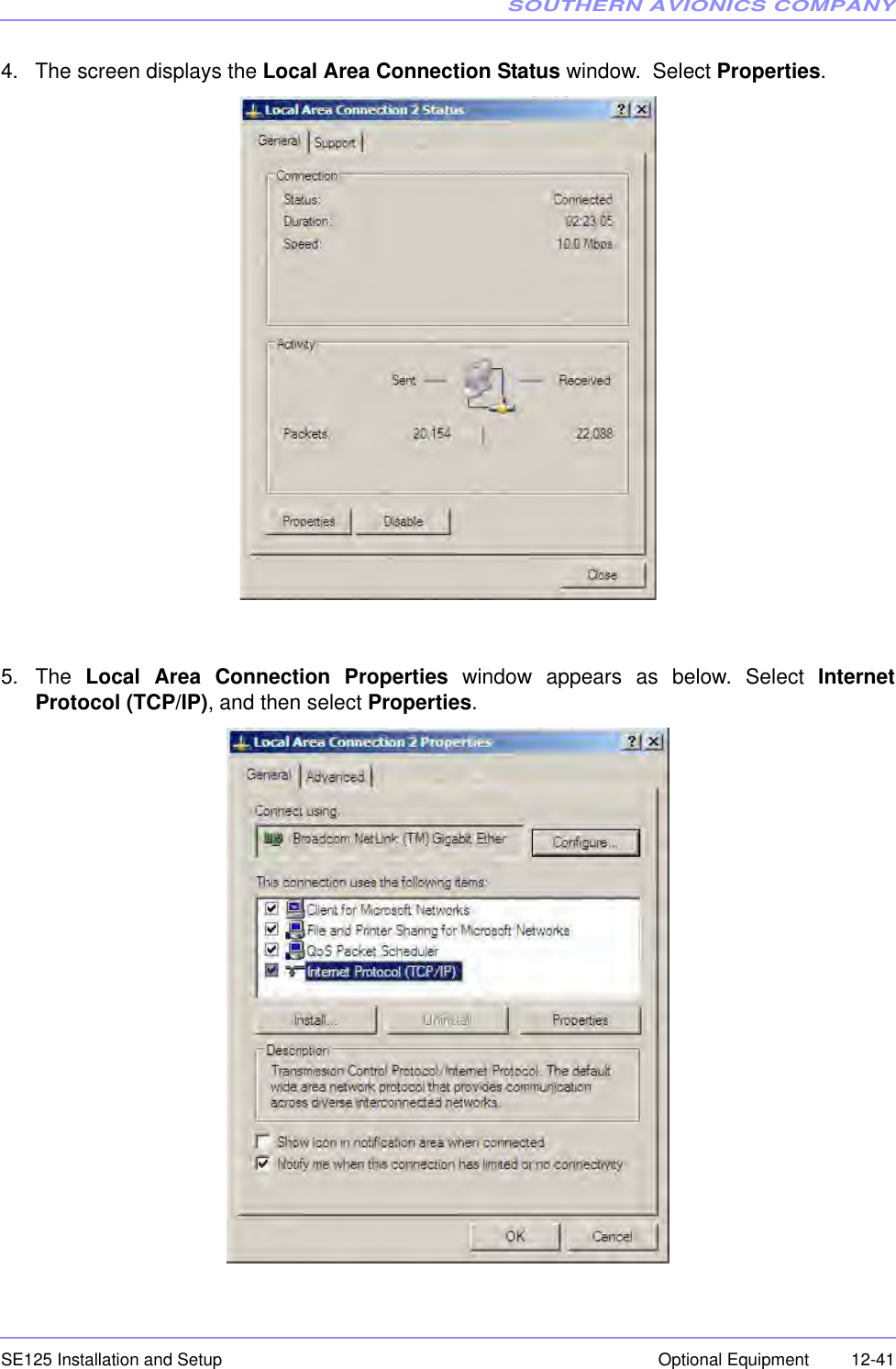
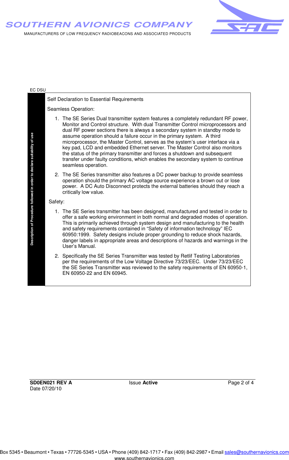
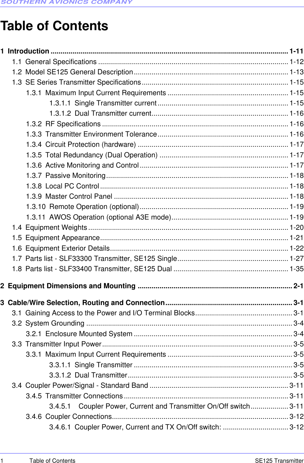
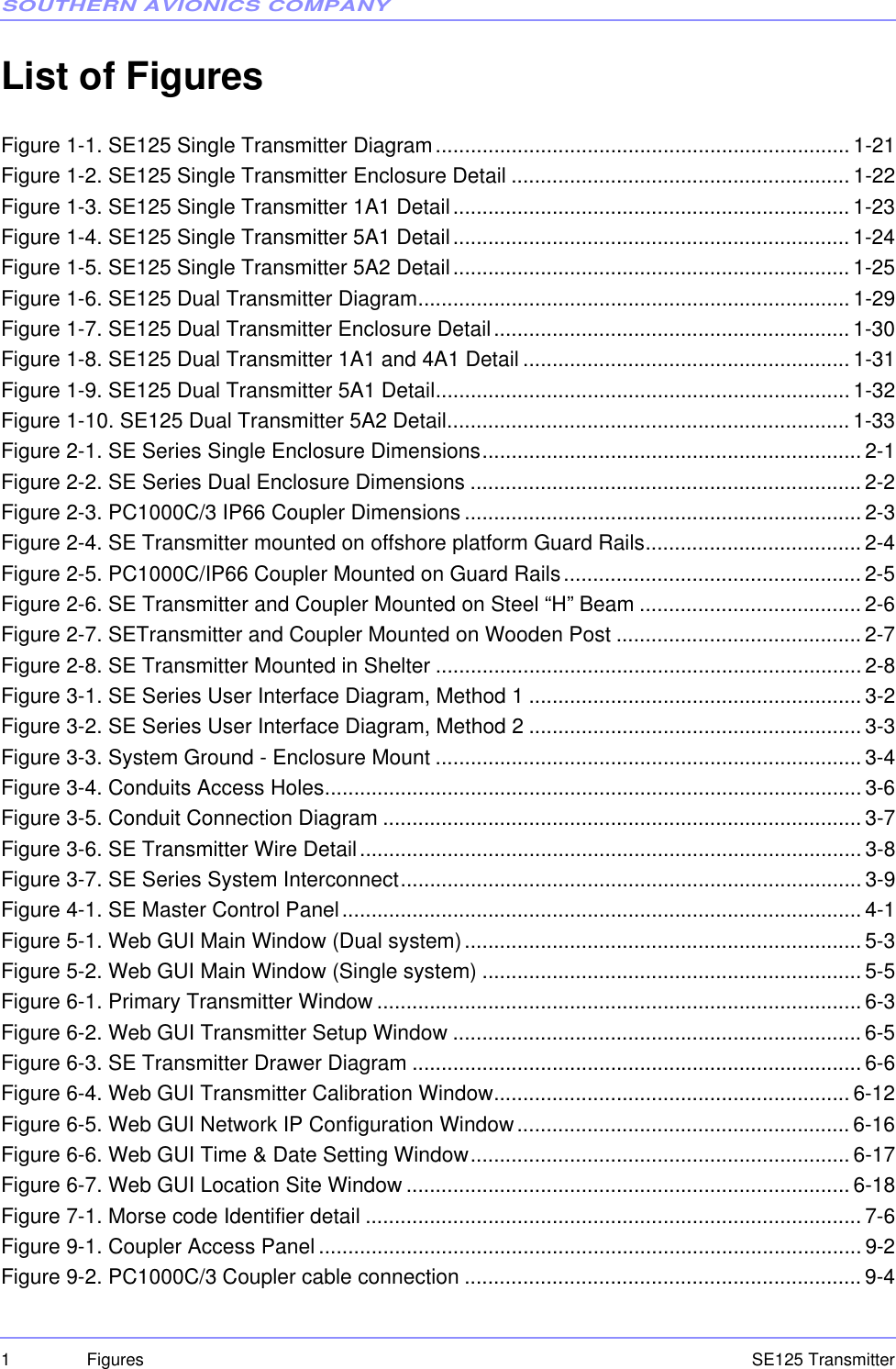
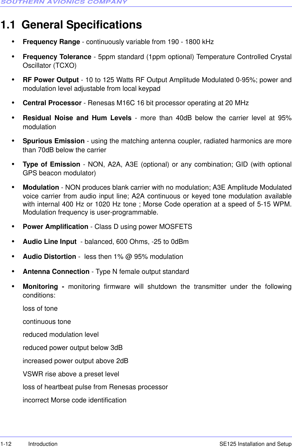
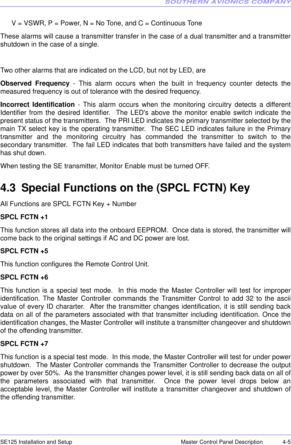
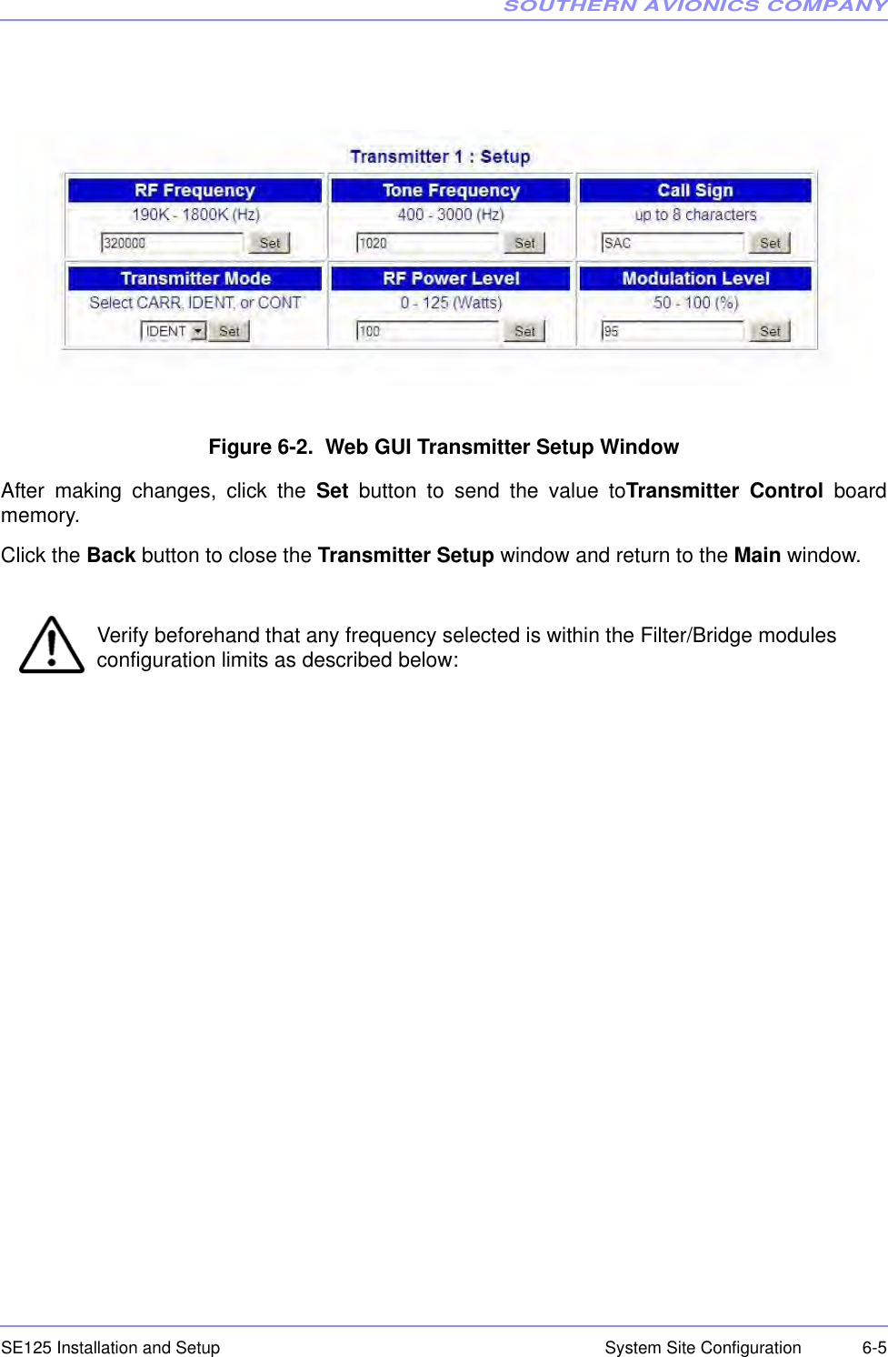
![SOUTHERN AVIONICS COMPANYSE125 Installation and Setup6-10 System Site Configuration6.4.6 Modulation Level SetupLCD DISPLAYPress the MOD LEVEL key to open the MODULATION SETTING menu, as shown belowRepeat pressing the MOD LEVEL key to clear the modulation level in the field box.Enter the mod level desired using the keypad.WEB WATCHOperates similar to the LCD DISPLAY above.6.5 Transmitter CalibrationThis section details how to calibrate the RF Frequency output, the RF output power, theModulator output and the RF power displayed.Using the SPCL FCTN key to open the special function menu as shown belowSelect the 8 key to open the calibration menu as shown below ---------- MODULATION SETTING --------- MOD Level should be between 50% and 100%. Enter Modulation Level: [ 95]% 1=STORE 7=PWR TEST 2=LOGGING 8=CALIBRATE 5=RCU 9=SYSTEM 6=ID TEST](https://usermanual.wiki/Southern-Avionics/SE125/User-Guide-1785097-Page-98.png)
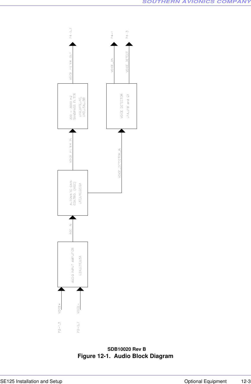
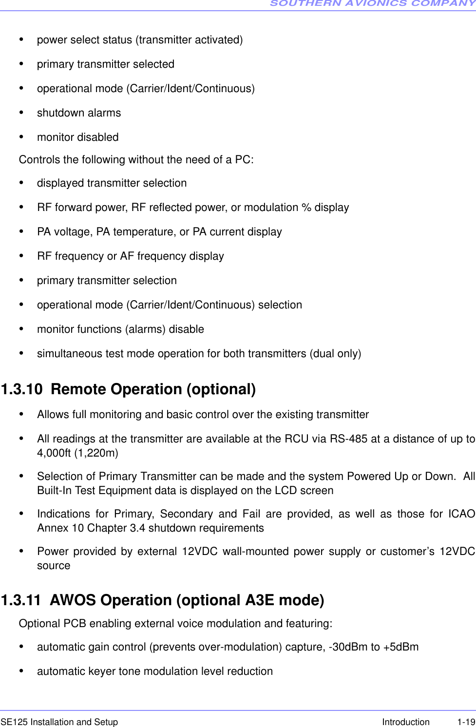
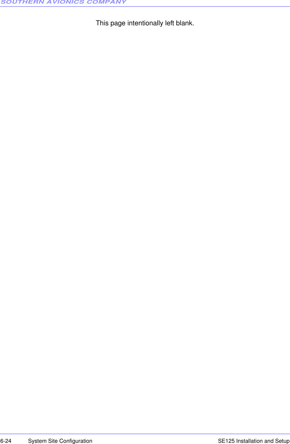
![SOUTHERN AVIONICS COMPANYSE125 Installation and Setup 6-11System Site Configuration6.5.1 RF (Power Factor) Calibration (Output adjustment)Transmitters are factory calibrated at 125W for an operating range of 10-125 Watts. If desiredoperating range is 10-25 Watts, the Transmitter must be calibrated at 25 Watts. Powercalibration should only be done locally with the system connected to a 50 Ohm dummy load, orincorrect readings could result.LCD DISPLAYPress the 1 key to open the POWER FACTOR CALIBRATION menu, as shown below.Enter the Power Factor value in the field box to make the value measured, by either a powermeter or oscilloscope, agree with the output power selected. If the measurement is being madeusing an oscilloscope, the power factor value should be adjusted until the waveform’s peak-to-peak voltage reaches the correct value. Observe that the value displayed in the Forward Power comes into agreement with the truepower measured by the power meter or the oscilloscope.Press the ENTER key to store then exit. Select the following key ---------------1.Power Factor Cal 4.Power Display Error 2.MOD Factor Cal 5.Tone Calibration 3.Frequency Cal 6.Anteena Current Cal ------ POWER FACTOR CALIBRATION ------- Power Factor should be between 5 and 250. Enter power factor: [100] LOADDUMMY2PP R22VP¸¸¹·¨¨©§](https://usermanual.wiki/Southern-Avionics/SE125/User-Guide-1785097-Page-99.png)
![SOUTHERN AVIONICS COMPANYSE125 Installation and Setup6-12 System Site ConfigurationWEB WATCH (Locally connected)In the SE SERIES TRANSMITTER Web Watch window, click on Calibration in the right column box on the Main window to open the Transmitter 1 : Calibration window shown in Figure 6-4. Web GUI Transmitter Calibration Window on Page 6-12.Operation is similar to the LCD DISPLAY above. Click set to save the change. Figure 6-4. Web GUI Transmitter Calibration Window6.5.2 Modulation Factor Calibration (display adjustment)LCD DISPLAYPress the 2 key to open the MODULATION CALIBRATION menu, as shown below.Set the modulation level to 100%. Verify that this is actually 100% modulation by monitoring theRF waveform envelope on the dummy load. Vary the MOD Factor and press enter. Do this untilthe scope displayed modulation is 95%. --- MODULATION FACTOR CALIBRATION --- MOD Factor should be between 5 and 250. Enter modulation factor: [100]](https://usermanual.wiki/Southern-Avionics/SE125/User-Guide-1785097-Page-100.png)
![SOUTHERN AVIONICS COMPANYSE125 Installation and Setup6-14 System Site ConfigurationChange the factor number and press return to achieve the proper LCD RF power readoutagreeing with the scope.WEB WATCHOperates similar to the LCD Display above. 6.5.5 Tone CalibrationSet Tone to 1020Hz. Enter the tone factor to agree with 95% modulation seen on the scope, thenstore by using SPCL FCTN +”1”. WEB WATCHOperates similar to the LCD Display above. 6.5.6 Antenna CalibrationLCD DISPLAYOperates similar to the Web Watch below. WEB WATCH•Under Calibration, verify the antenna factor is set to 100 (default).•The displayed value of antenna current should be made to agree with the value on the ATU meter by adjusting the factor until identical readings are achieved.When the transmitter calibration is complete, click the Back button to close the TransmitterCalibration window and return to the Main window. ---- POWER DISPLAY ERROR CALIBRATION --- P.D.E Factor should be between 5 and 250. Enter display error factor: [100]](https://usermanual.wiki/Southern-Avionics/SE125/User-Guide-1785097-Page-102.png)
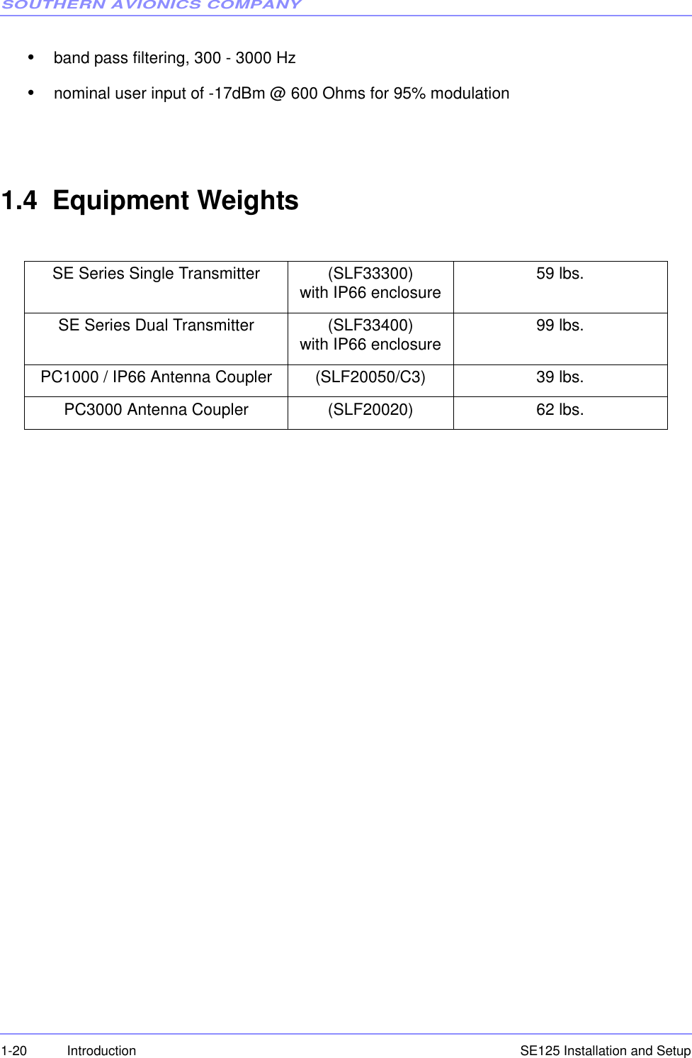
![SOUTHERN AVIONICS COMPANYSE125 Installation and Setup 6-15System Site Configuration6.6 DCAD (DC Automatic Disconnect)LCD DISPLAYPress the SPCL FCTN key, then the 9 key to open the SE SYSTEM menu, as shown below.Press the 1 key to toggle “ON” or “OFF” on the LCD screen, then the ENTER key to exit. ENTERmust be pressed to store the selection or it will be lost. WEB WATCH(Not available)6.7 Network IP ConfigurationLCD DISPLAYPress the SPCL FCTN key, then the 9 key to open the SE SYSTEM menu, as shown below.Press the 2 key to open the Network IP on the LCD screen, then select one of the followingnumbers: -------------- SE SYSTEM ------------- 1. DCAD . . . . . . . . . . . . . . [OFF] 2. Network Press ENTER key to confirm, then exit. -------------- SE SYSTEM ------------- 1. DCAD . . . . . . . . . . . . . . [OFF] 2. Network Press ENTER key to confirm, then exit.](https://usermanual.wiki/Southern-Avionics/SE125/User-Guide-1785097-Page-103.png)
![SOUTHERN AVIONICS COMPANYSE125 Installation and Setup6-16 System Site Configuration1. DHCP2. IP Address3. Netmask4. GatewayPress the Enter key to confirm the Network IP settings.WEB WATCH (Read Only)In the SE SERIES TRANSMITTER Web Watch window, click on the IP Configuration from theright column box on the Main menu to open the Network : IP Configuration window, shown inFigure 6-5. Web GUI Network IP Configuration Window on Page 6-16.Figure 6-5. Web GUI Network IP Configuration Window 1. DHCP: [ENABLED] 2. IP Address: 192.168.1.122 3. Netmask: 255.255.255.0 Press ENTER 4. Gateway: 192.168.1.1 to confirm](https://usermanual.wiki/Southern-Avionics/SE125/User-Guide-1785097-Page-104.png)
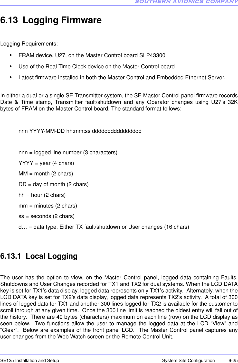
![SOUTHERN AVIONICS COMPANYSE125 Installation and Setup 6-19System Site Configuration6.10 Monitor EnableLCD DISPLAYPress the ENABLE key to open the MONITOR menu, as shown below (transmitter 1 is selected).Press ENABLE to toggle “ENABLED” or “DISABLED” on the LCD screen, then the ENTER keyto exit. ENTER must be pressed to store the selection.WEB WATCHOperates similar to the LCD DISPLAY above.6.11 Transmitter DataUsing the DOWN or UP arrow key to view the following previous or next menu as below: ------------ TRANSMITTER 1 ----------- MONITOR . . . . . . . . . . . . [ENABLED] Press ENTER key to confirm, then exit. ------------ TRANSMITTER 1 ----------- FORWARD PWR : 100W VSWR : 1.00 RFFLECTED PWR: 0W ANTENNA(I): 2.4A MODULATION: 95% FREQ : 320000HZ ------------ TRANSMITTER 1 ----------- PWM DRV LVL: 4.9V MOD DRV LVL: 1.3V FILTER +5V : 5.0V BTRY CHARGE: 2.7A BTRY DISCH : 2.1A](https://usermanual.wiki/Southern-Avionics/SE125/User-Guide-1785097-Page-107.png)
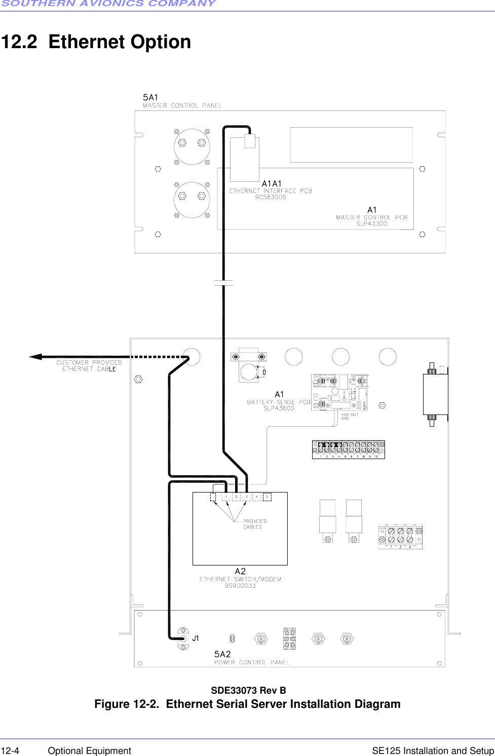
![SOUTHERN AVIONICS COMPANYSE125 Installation and Setup7-2 Operational Checks7.5 Transmitter #1 RF Power Level Checks7.5.1Connect an oscilloscope or a calibrated power meter to the system's RF output at the dummy load.7.5.2Use the MAIN TX key to select TX1 as primary transmitter. Green LED’s will illuminate indicatingwhich TX is Primary. Select TX1 as Primary.7.5.3Use the LCD DATA key to select TX1 as the display / control transmitter data.7.5.4In the Monitor section press the ENABLE key until “Disabled” is displayed on the LCD. PressENTER to store this condition. This action will be necessary until shutdown testing is performedlater in this section.7.5.5Press the FREQ key to open the RF FREQUENCY ENTRY menu, as shown below. SE SERIES [DUAL] Fault: NONE RF Frequency Setting ......... 320000 Hz Tone Frequency Setting ....... 1020 Hz Call Sign: SAC TX Mode:IDENT RF FREQUENCY ENTRY FREQ should be between 190K and 1800K Hz Enter RF Frequency: [ 320000] Hz](https://usermanual.wiki/Southern-Avionics/SE125/User-Guide-1785097-Page-124.png)
![SOUTHERN AVIONICS COMPANYSE125 Installation and Setup 7-3Operational Checks7.5.6Enter the desired frequency of operation using the numeric keypads then press ENTER to storethe selection. (If necessary press the FREQ key repeatedly to clear the RF frequency field). 7.5.7Press the TONE key to toggle between 400 Hz and 1020 Hz modulation frequency.7.5.8Enter the desired call-sign using the numeric keypads then press ENTER to store the selection.Press the CALL SIGN key to open the CALL SIGN ENTRY menu, as shown below. (Ifnecessary press the CALL SIGN key repeatedly to clear the call sign field). 7.5.9Press the MODE key to toggle the CARR, IDENT, CONT., to Carrier Mode (CARR).7.5.10Press the OUTPUT POWER key to open the RF POWER SETTING menu, as shown below.7.5.11Key in the desired power level for the site and press ENTER to store and activate that level. In afew seconds, the power output level selected should register on the meter and voltage on the PAmeter should be indicated. CALL SIGN ENTRY Enter 1 to 8 Characters Entry Call Sign : SAC ---------- RF POWER SETTING ---------- POWER should be 0 through 125 Enter RF Power Level: [100] Watts](https://usermanual.wiki/Southern-Avionics/SE125/User-Guide-1785097-Page-125.png)
![SOUTHERN AVIONICS COMPANYSE125 Installation and Setup7-4 Operational ChecksRecord the readings for PA voltage and PA current for reference data to be used in Section10 for proper Antenna tuning and matching. 7.5.12Verify the output RF power level measured at the dummy load agrees (within 5%) with the valuedisplayed on the LCD in the Transmitter 1 section.7.6 Transmitter #1 Modulation Level Check7.6.1Press the MOD LEVEL key to open the MODULATION SETTING menu, as shown below.Press the MOD LEVEL key repeatedly to clear the modulation level box.Enter 95% modulation and press ENTER to store that level.7.6.2Scope the modulation waveform and record the max/min envelope values to calculate themodulation percentage. (vmax-vmin)/(vmax+vmin)=mod%7.6.3Verify the set modulation percentage (displayed on the LCD) and the calculated modulationpercentage agree to within 5%. ---------- MODULATION SETTING --------- MOD Level should be between 50% and 100%. Enter Modulation Level: [ 95]%](https://usermanual.wiki/Southern-Avionics/SE125/User-Guide-1785097-Page-126.png)
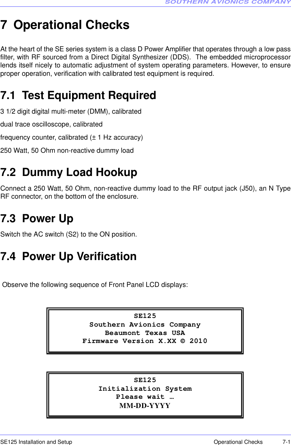
![SOUTHERN AVIONICS COMPANYSE125 Installation and Setup 7-7Operational Checks7.8.2This completes general operational tests of transmitter #1.7.9 Transmitter #2 RF Power Level Checks (Dual systems)7.9.1Connect an oscilloscope or a calibrated power meter to the system's RF output at the dummy load.7.9.2Use the MAIN TX key to select TX2 as primary transmitter. Green LED’s will illuminate indicatingwhich TX is Primary. Select TX2 as Primary.7.9.3Use the LCD DATA key to select TX2 as the display / control transmitter data.7.9.4In the Monitor section press the ENABLE key until “Disabled” is displayed on the LCD. PressENTER to store this condition. This will be necessary until shutdown testing is performed later inthis section.7.9.5Press the FREQ key to open the RF FREQUENCY ENTRY menu, as shown below.7.9.6Enter the desired frequency of operation using the numeric keypads then press ENTER to storethe selection. (If necessary press the FREQ key repeatedly to clear the RF frequency field). RF FREQUENCY ENTRY FREQ should be between 190K and 1800K Hz Enter RF Frequency: [ 320000] Hz](https://usermanual.wiki/Southern-Avionics/SE125/User-Guide-1785097-Page-129.png)
![SOUTHERN AVIONICS COMPANYSE125 Installation and Setup7-8 Operational Checks7.9.7Press the TONE key to toggle between 400 HZ and 1020 HZ modulation frequency.7.9.8Enter the desired call-sign using the numeric keypads then press ENTER to store the selection.Press the CALL SIGN key to open the CALL SIGN ENTRY menu, as shown below. 7.9.9Press the MODE key to toggle the CARR, IDENT, CONT. to Carrier Mode (CARR).7.9.10Press the OUTPUT POWER key to open the RF POWER SETTING menu, as shown below.7.9.11Key in the desired power level for the site and press ENTER to store and activate that level. In afew seconds, the power output level selected should register on the meter and voltage on the PAmeter should be indicated.7.9.12Verify the output RF power level measured at the dummy load agrees (within 5%) with the valuedisplayed on the LCD in the Transmitter 2 section. CAL SIGN ENTRY Enter 1 to 8 Characters Entry Call Sign: SAC ---------- RF POWER SETTING ---------- POWER should be 0 through and 125. Enter RF Power Level: [100] Watts](https://usermanual.wiki/Southern-Avionics/SE125/User-Guide-1785097-Page-130.png)
![SOUTHERN AVIONICS COMPANYSE125 Installation and Setup 7-9Operational Checks7.10 Transmitter #2 Modulation Level Check7.10.1Press the MOD LEVEL key to open the MODULATION SETTING menu, as shown below.Press the MOD LEVEL key repeatedly to clear the modulation level box.Enter 95% modulation and press ENTER to store that level.7.10.2Scope the modulation waveform and record the max/min envelope values to calculate themodulation percentage. (vmax-vmin)/(vmax+vmin)=mod%7.10.3Verify the set modulation percentage (displayed on the LCD) and the calculated modulationpercentage agree to within 5%.7.11 Transmitter #2 Frequency Checks7.11.1As an example, when calibrating RF output frequency, International Civil Aviation Organization(ICAO) regulations state a maximum variance of + 100 parts per million (ppm) Hertz is allowedprovided the ouput frequency is less than 1606.5 kHz. ---------- MODULATION SETTING --------- MOD Level should be between 50% and 100%. Enter Modulation Level: [ 95]%](https://usermanual.wiki/Southern-Avionics/SE125/User-Guide-1785097-Page-131.png)

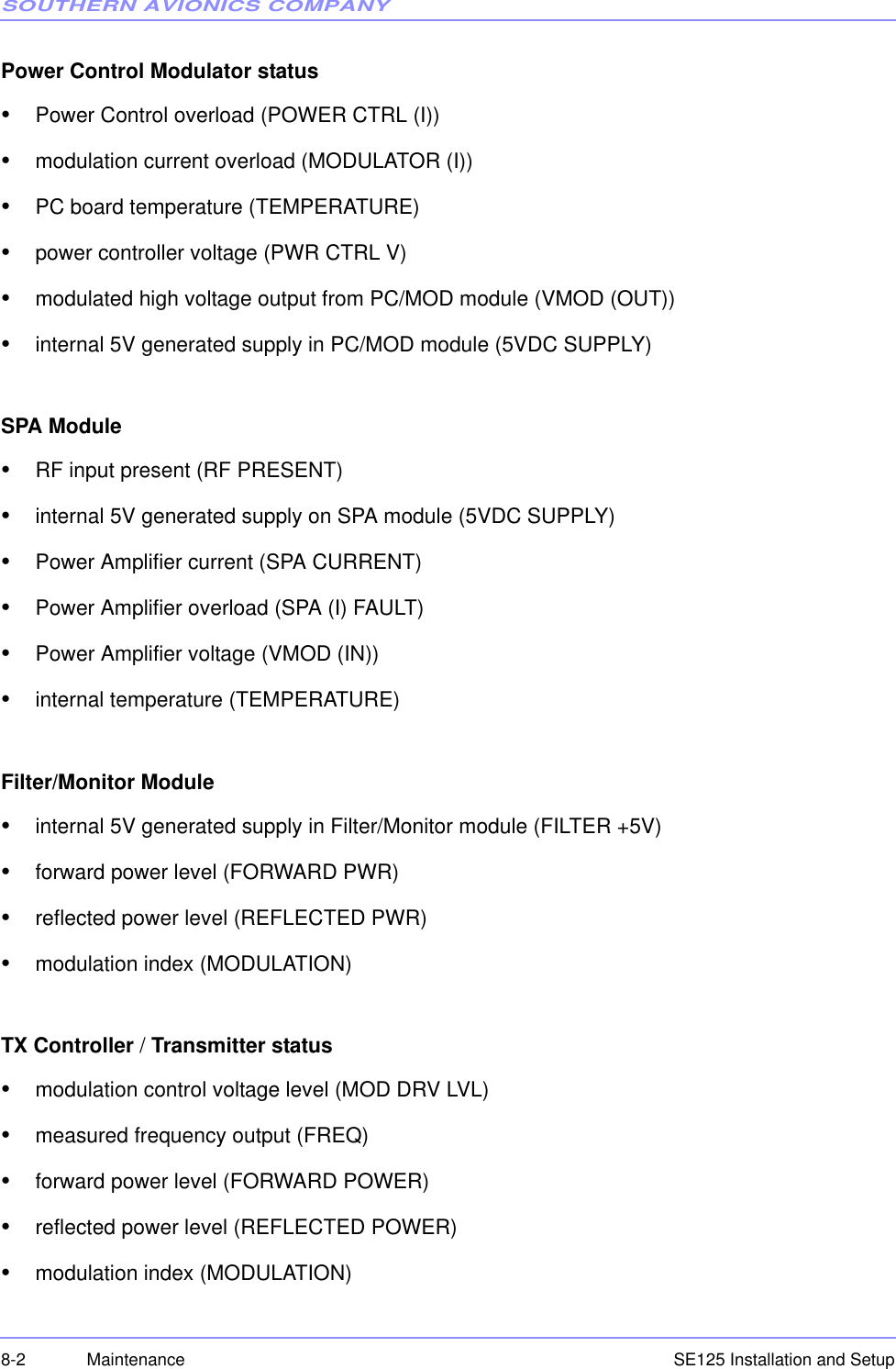
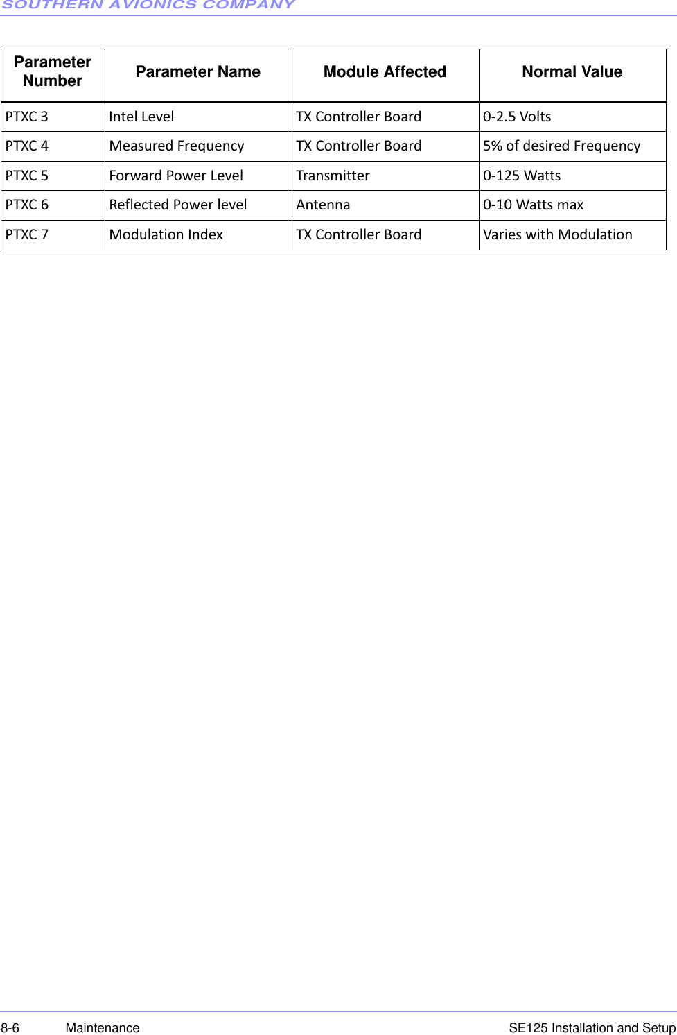
![SOUTHERN AVIONICS COMPANYSE125 Installation and Setup 8-1Maintenance8 Maintenance8.1 Built In Test Equipment (BITE)The SE125 has extensive BITE features that give the technician on site the ability to troubleshootthe transmitter. Every stage in the transmitter has built in monitors to allow the technician totroubleshoot down to an individual stage. As the signal is created and amplified, each step iscarefully monitored for correct operation. Each monitored function for each module in the SE isdescribed below.Note: Certain parameters such as shutdown LED’s and overload LED’s are displayed as LED’son the hardware and on the web browser connected to the Ethernet interface. They will bedisplayed as a “Yes” or “No” on the LCD screen implementation of BITE8.1.1 BITE parametersBattery Backup/Power supply status•input 48VDC from battery backup source (BTRY SAMPLE)•charging current supplied to the battery backup source (BTRY CHARGE)•DC current supplied to the SE transmitter (BTRY DISCH)•Power Supply High Voltage DC (PWR SUPPLY [V])LVREG/HVPS Module•input 48VDC voltage (PWR SUPPLY [V])•output high voltage supplied to the PC/MOD module (HV OUTPUT)•high side FET current draw on high voltage oscillator output stage (HIGH SIDE [I])•low side FET current draw on high voltage oscillator output stage (LOW SIDE [I])•supply 12VDC provided by LVREG/HVPS module (12VDC SUPPLY)•internal 5VDC generated within LVREG/HVPS module (5VDC SUPPLY)•internal temperature (TEMPERATURE)](https://usermanual.wiki/Southern-Avionics/SE125/User-Guide-1785097-Page-139.png)