Southern Avionics SE125 Non-directional radio beacon User Manual SE 125 Installation and Setup
Southern Avionics Company Non-directional radio beacon SE 125 Installation and Setup
Users Manual

Box 5345 • Beaumont • Texas • 77726-5345 • USA • Phone (409) 842-1717 • Fax (409) 842-2987 • Email sales@southernavionics.com
www.southernavionics.com
MANUFACTURERS OF LOW FREQUENCY RADIOBEACONS AND ASSOCIATED PRODUCTS
SOUTHERN AVIONICS COMPANY
SE Series Transmitter
SE125
Digital Non-Directional Beacon
Installation and Setup Manual
Manual #SD433001
Revision M
This material is and shall remain the proprietary and confidential property of Southern Avionics
Company Inc. and no part thereof shall be copied, disclosed to others or used in connection with
any work or project other than the specific project for which it has been prepared and developed
without the written consent of Southern Avionics Company.
Printed
May 14, 2012

Box 5345 • Beaumont • Texas • 77726-5345 • USA • Phone (409) 842-1717 • Fax (409) 842-2987 • Email sales@southernavionics.com
www.southernavionics.com
MANUFACTURERS OF LOW FREQUENCY RADIOBEACONS AND ASSOCIATED PRODUCTS
SOUTHERN AVIONICS COMPANY
STANDARD LIMITED WARRANTY
Southern Avionics Company (hereinafter called SAC) warrants to the original Purchaser for a period of
Fourteen (14) months from the date of shipment to the original Purchaser, that the goods sold under this
warranty were at the time of the delivery, free from defects resulting from faulty material or workmanship.
This limited warranty is in lieu of all other representations and express warranties and is made for the
benefit of the original purchaser only and is not made for the benefit of any party other than original
Purchaser. All implied warranties existing under the law are hereby expressly negated; particularly, SAC
hereby negates and disclaims the implied warranty of merchantability and implied warranty of fitness for a
particular purpose.
This warranty applies only if the goods are submitted to normal use and service and does not apply if the
goods are misused or mismatched with other goods such as antennas, couplers, or any other third party
goods, which have not been approved by SAC in writing, for use with SAC equipment.
If Purchaser believes that these goods do not comply with the express warranty stated above, or any
existing and applicable implied warranty which under the law cannot be disclaimed, or negated, as
provided above, then Purchaser may request that SAC inspect such goods using the following contact
information: telephone: +409-842-1717; fax: +409-842-2987; email: sales@southernavionics.com; or, by
shipping the goods prepaid to SAC at 5055 Belmont Street, Beaumont, Texas, 77707 U.S.A. to the
attention of Warranty Repair, within Sixty (60) days after Purchaser knows, or should have known, that the
goods allegedly do not conform with the warranty.
Shipments must include written documentation specifying (a) Purchaser's name, address, telephone
number and email address, (b) date of purchase, (c) Serial Number(s) of the equipment (d) location from
which the goods were purchased, (e) location of the installation, and (f) description of the alleged
nonconformity with the warranty.
If the goods are covered by this warranty and SAC’s determines that they do not conform to the terms
herein, SAC will repair or replace the goods and return them F.O.B. point of manufacture. In no event will
SAC be obligated or required to remove the non-conforming goods from their place of installation and/or to
install any replacement goods. All replacement goods are warranted to the extent provided herein for the
remaining term of this warranty.
In the event purchaser chooses to commence an action for breach of warranty or breach of contract arising
out of the sale of the goods pursuant to this invoice, the purchaser must commence such action within One
(1) year after the course of action accrues. The remedy provided herein shall be the sole and exclusive
remedy for breach of this warranty, for any breach of any implied warranty existing and applicable under
the laws of the United States of America (to the extent that any such warranty has not been successfully
negated and disclaimed hereinabove) and for any act of negligence or other tortuous act committed by
SAC, and in no event shall SAC be liable to the Purchaser or any third party for any incidental,
consequential or special damages resulting from any defect in the goods or any failure of the goods to
conform with this warranty or any implied warranty existing and applicable under U.S. law (to the extent
that any such implied warranty has not been successfully negated and disclaimed hereinabove.)
SD9SD001 Rev D

Box 5345 • Beaumont • Texas • 77726-5345 • USA • Phone (409) 842-1717 • Fax (409) 842-2987 • Email sales@southernavionics.com
www.southernavionics.com
MANUFACTURERS OF LOW FREQUENCY RADIOBEACONS AND ASSOCIATED PRODUCTS
SOUTHERN AVIONICS COMPANY
REPAIR POLICY
Southern Avionics Company (SAC) offers fault analysis, repair and refurbishment of SAC equipment
performed by our factory-trained staff.
Items submitted for repair must be accompanied by an Return Merchandise Authorization (RMA) number
which will enable us to address your request in the most efficient manner.
Contact our Technical Department to receive RMA before returning items to SAC.
In order for us to process your repair order, the equipment sent for repair must include the following
information:
(a) RMA
(b) Purchaser's name, address, telephone number and email address,
(c) Serial Number of the equipment
(d) location of the installation, and
(e) detailed description of problem / reason for repair
Standard repair labor rate: $150 USD per hour.
Minimum repair cost: $150 USD.
Standard repair turnaround time: 14 days, excluding shipping time.
Turnaround time of less than 14 days will be subject to an expediting fee of $50 USD per hour in addition
to the standard repair labor rate.
SAC will notify the customer if we determine that the returned item cannot be economically repaired, or if it
is more cost-effective to purchase a new item.
Items that we conclude cannot be repaired to meet our established standard of performance will be
rejected and returned to the customer, upon request. Pads lifted from circuit boards or burned circuit
boards are examples of non-repairable items.
Customer is responsible for all freight costs. SAC assumes no responsibility for any loss or damage of
items sent for repair.
Repairs are guaranteed for 90 days after shipment. Warranty applies only to the actual repairs that were
made and does not cover any subsequent equipment failures not associated with the previous repair.
SD9SD003 Rev D
Phone: +409-842-1717 ext. 107
Fax: +409-842-2987
Email: techdept@southernavionics.com
Box 5345 • Beaumont • Texas • 77726-5345 • USA • Phone (409) 842-1717 • Fax (409) 842-2987 • Email sales@southernavionics.com
www.southernavionics.com
MANUFACTURERS OF LOW FREQUENCY RADIOBEACONS AND ASSOCIATED PRODUCTS
SOUTHERN AVIONICS COMPANY
Council Directive 1999/5/EC R&TTE Label
This system is intended for use in professional environment by personnel fully conversant with its
use and application. It should not be operated in close proximity to domestic electrical
equipment.
This system is to be operated and maintained by skilled staff in strict accordance with the
manufacturer’s instructions. The use of service spares not recommended by the manufacturer
may compromise the electromagnetic compatibility of the equipment.
It is the responsibility of the user to ensure that any external cabling, test leads, and/or other user
supplied fixtures are designed, manufactured, and maintained in accordance with engineering
practices appropriate for their intended use.
SS210050 Rev B

Box 5345 • Beaumont • Texas • 77726-5345 • USA • Phone (409) 842-1717 • Fax (409) 842-2987 • Email sales@southernavionics.com
www.southernavionics.com
MANUFACTURERS OF LOW FREQUENCY RADIOBEACONS AND ASSOCIATED PRODUCTS
SOUTHERN AVIONICS COMPANY
CE DECLARATION OF CONFORMITY
In accordance with the Council of the European Communities, Southern Avionics hereby declares
Conformance of the product described below with the following Directives.
Reference: Notified Body Certificate 1000- 1 - 1513P
Southern Avionics Company has demonstrated compliance with the Essential Requirements of Council
Directive 1999/5/EC on Radio Equipment and Telecommunications Terminal Equipment with specific
requirements in the following areas:
73/23/EEC European Community Low voltage directive
EN 60950-1:2006, EN 60950-22:2006 and EN 60945:2002
2004/108/EC EMC directive
EN 61000-6-2:2005, EN 61000-6-4:2007, CISPR 16-2-1:2008, CISPR 16-2-3:2010, IEC
61000-3-2:2009, IEC 61000-3-3:2008, IEC 61000-4-2:2008, IEC 61000-4-3:2008, IEC
61000-4-4:2004, IEC 61000-4-5:2005, IEC 61000-4-6:2008, IEC 61000-4-8:2009, IEC
61000-4-11:2004
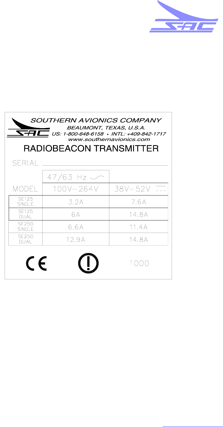
Equipment Description:
This Declaration covers all single and dual SE125 and SE250 Series Non Directional Beacon
Transmitters in the following frequency bands: Standard 190 kHz – 650 kHz, Medium 500 kHz –
1250 kHz and High 1500 kHz – 1800 kHz.
European Agent: Muirhead Avionics
Mallory House
Navigator Park
Southall Lane, Southall
Middlesex UB2 5NH - UK
Tel: +44.2085.713422
Company Signatory:
Tim Hamilton
Date: July 19, 2010
Director of Engineering
Southern Avionics Company
P.O. Box 5345
Beaumont, Texas, USA 77726-5345
409-842-1717(tel) 409-842-2987(fax)
SD0EN020 REV A Page 1 of 1

Box 5345 • Beaumont • Texas • 77726-5345 • USA • Phone (409) 842-1717 • Fax (409) 842-2987 • Email sales@southernavionics.com
www.southernavionics.com
MANUFACTURERS OF LOW FREQUENCY RADIOBEACONS AND ASSOCIATED PRODUCTS
SOUTHERN AVIONICS COMPANY
EC DSU
SD0EN021 REV A Issue Active Page 1 of 4
Date 07/20/10
Interoperability Declaration
SE Series Transmitter EC Declaration of Suitability for Use
Regulation
Reference
Regulation (EC) No 552/2004 Of The European Parliament And Of The Council Of 10
March 2004 on the Interoperability of the European Air Traffic Management Network (The
Interoperability Regulation)
Name & address of Manufacturer or
Agent
Southern Avionics Company
5050 Belmont
Beaumont, Texas 77707
Muirhead Avionics
Mallory House
Navigator Park
Southall Lane, Southall
Middlesex UB2 5NH - UK
Tel: +44.2085.713422
Description of the constituent
Southern Avionics Company’s SE series Transmitters with PC1000C/3, PC1000M/3,
PC1000H/3 or PC3000 Antenna Tuning Units (ATU) and Remote Control Unit (RCU)
have been designed and tested to operate as a standalone Non Directional radio Beacon
system for airplane navigation as part of the Air Traffic Management network. The SE
series Transmitter may also be used as an Inner or Outer Marker Beacon utilized during
an aircraft’s approach to land. This system has been designed to operate on land,
offshore platforms or maritime vessels. The system develops an output power of 10-125
Watts (SE125) or 50-250 Watts (SE250) with a frequency range of 190kHz to 1250kHz.
The system is intended to operate up to an Amplitude Modulation level of 100% while
communicating an alpha numeric Morse Code identifier via on/off keying. The
transmitter’s input voltage requirements are 100-264VAC at 47-63Hz or 48VDC. The
ATU’s operating voltage, +12VDC, is provided by the SE Transmitter or local power
supply. The RCU’s input voltage requirement is +12VDC provided by a wall mounted
power supply or a customer provided +12VDC backup.

Box 5345 • Beaumont • Texas • 77726-5345 • USA • Phone (409) 842-1717 • Fax (409) 842-2987 • Email sales@southernavionics.com
www.southernavionics.com
MANUFACTURERS OF LOW FREQUENCY RADIOBEACONS AND ASSOCIATED PRODUCTS
SOUTHERN AVIONICS COMPANY
EC DSU
SD0EN021 REV A Issue Active Page 2 of 4
Date 07/20/10
Description of Procedure followed in order to declare suitability of use
Self Declaration to Essential Requirements
Seamless Operation:
1. The SE Series Dual transmitter system features a completely redundant RF power,
Monitor and Control structure. With dual Transmitter Control microprocessors and
dual RF power sections there is always a secondary system in standby mode to
assume operation should a failure occur in the primary system. A third
microprocessor, the Master Control, serves as the system’s user interface via a
key pad, LCD and embedded Ethernet server. The Master Control also monitors
the status of the primary transmitter and forces a shutdown and subsequent
transfer under faulty conditions, which enables the secondary system to continue
seamless operation.
2. The SE Series transmitter also features a DC power backup to provide seamless
operation should the primary AC voltage source experience a brown out or lose
power. A DC Auto Disconnect protects the external batteries should they reach a
critically low value.
Safety:
1. The SE Series transmitter has been designed, manufactured and tested in order to
offer a safe workin
g
environment in both normal and de
g
raded modes of operation.
This is primarily achieved through system design and manufacturing to the health
and safety requirements contained in “Safety of information technology” IEC
60950:1999. Safety designs include proper grounding to reduce shock hazards,
danger labels in appropriate areas and descriptions of hazards and warnings in the
User’s Manual.
2. Specifically the SE Series Transmitter was tested by Retlif Testing Laboratories
per the requirements of the Low Voltage Directive 73/23/EEC. Under 73/23/EEC
the SE Series Transmitter was reviewed to the safety requirements of EN 60950-1,
EN 60950-22 and EN 60945.

Box 5345 • Beaumont • Texas • 77726-5345 • USA • Phone (409) 842-1717 • Fax (409) 842-2987 • Email sales@southernavionics.com
www.southernavionics.com
MANUFACTURERS OF LOW FREQUENCY RADIOBEACONS AND ASSOCIATED PRODUCTS
SOUTHERN AVIONICS COMPANY
EC DSU
SD0EN021 REV A Issue Active Page 3 of 4
Date 07/20/10
Description of Procedure followed in order to declare suitability of use
Self Declaration to Essential Requirements (continued)
Environmental Constraints:
1. The SE Series Transmitter meets or exceeds the requirements of 2002/95/EC on
the restriction of the use of certain hazardous substances in electrical and
electronic equipment. Design and construction to the requirements of this directive
minimizes or eliminates the concentration of lead, mercury, cadmium, hexavalent
chromium, polybrominated biphenyls or polybrominated diphenyl ethers used in
the SE Series Transmitter system.
2. The SE Series Transmitter utilizes an outside enclosure rated to Ingress Protection
(IP) 66, which was tested to the international standard IEC 60529 Edition 2.1,
2001-02.
3. The SE Series Transmitter is intended to be used in ambient temperature
conditions between -30 and +70 degrees Celsius.
4. The SE Series Transmitter is intended to be used in a non condensing relative
humidity environment with humidity ranging from 0 to 95%.
5. The IP66 rated SE Series Transmitter is suitable for use in high salinity
environments as encountered in offshore conditions.
6. The SE Series transmitter should not be used above 10,000 feet (3048 meters).
Principles governing the logical architecture of systems:
1. The SE Series Transmitter system is designed on a fully redundant platform based
on an architecture used by Southern Avionics Company, which has been sold in
the EU for many years. As an option the SE Series design employs an embedded
server using an Ethernet protocol for ease of local and remote interface via
Ethernet or the Internet.
Description of Procedure followed in
order to declare suitability of use
Principles governing the construction of systems:
1. The SE Series Transmitter is designed to maximize modularity of critical printed
circuit boards in both the Master Control and RF Transmitter sections. This
concept allows the fastest upgrade of failed boards without the need for special
tools. The design also affords high availability due to its solid-state design and full
system redundancy.

Box 5345 • Beaumont • Texas • 77726-5345 • USA • Phone (409) 842-1717 • Fax (409) 842-2987 • Email sales@southernavionics.com
www.southernavionics.com
MANUFACTURERS OF LOW FREQUENCY RADIOBEACONS AND ASSOCIATED PRODUCTS
SOUTHERN AVIONICS COMPANY
EC DSU
SD0EN021 REV A Issue Active Page 4 of 4
Date 07/20/10
Define the relevant provisions met by the constituent and in particular its conditions of use
The SE Transmitter system meets or exceeds the engineering, spectrum and operational
requirements defined in US Federal Communication Commission code of federal
regulation 47 Part 2 and Part 87, US Federal Aviation Agency Regulations part 171, The
Radio Regulation 2004, ICAO Annex 10 chapter 3.4 and UKCAA CAP 670 Part C Section
2. The SE system was tested to the Essential Requirements of Council Directive
1999/5/EC on Radio Equipment and Telecommunications Terminal Equipment. With
respect to the protection of health and safety the SE system was tested to directive
73/23/EEC and 2004/108/EC. These test results can be seen in the Technical Construct
File possessed by Muirhead Avionics, England which includes:
1. Declaration of Conformity
2. Low Voltage Directive 73/23/EEC test results
3. EMC Directive 2004/108/EC test results
4. Spurious Harmonics and Occupied Bandwidth test results
5. ICAO statement of compliance / SE Series Factory Acceptance Test
6. CE Marking and labelling
7. Southern Avionics Company Quality Manual
8. SE series Technical Manual
9. SE250 series Setup Manual
Name & Address of Notified
Body
Retlif Testing Laboratories
795 Marconi Avenue
Ronkonkoma, NY 11779
Date of Certificate Issue: July 19, 2010
Intended Use: Air Traffic Management
Notified Body No.: 1000
Identification of Signatory
Tim Hamilton
Director of Engineering
Signed : Date: July 19, 2010

Box 5345 • Beaumont • Texas • 77726-5345 • USA • Phone (409) 842-1717 • Fax (409) 842-2987 • Email sales@southernavionics.com
www.southernavionics.com
MANUFACTURERS OF LOW FREQUENCY RADIOBEACONS AND ASSOCIATED PRODUCTS
SOUTHERN AVIONICS COMPANY
This page intentionally left blank.

SOUTHERN AVIONICS COMPANY
Change Control Record
Change Control Record
Date Section Pages Change
SE125 Installation and Setup SD433001 Rev K
11-22-11 Section
44-5 Updated SPCL FCTN +6
Updated SPCL FCTN +7
SE125 Installation and Setup SD433001 Rev L
11-28-11 Section
11-24 Update SE125 Single Transmitter 5A1 Detail
11-28-11 Section
11-32 Update SE125 Dual Transmitter 5A1 Detail diagram
11-28-11 Section
44-1 Update SE Master Control Panel diagram
11-28-11 Section
12 12-16 Update Multi-Mode Ethernet to Fiber Optics Converter diagram
11-28-11 Section
12 12-24 Update Leased Line Modem diagram
11-28-11 Section
12 12-34 Update Ethernet Extender diagram
11-28-11 Section
12 12-37 Update Ethernet Radio link detail
SE125 Installation and Setup SD433001 Rev M
4-13-12 Section
11-27 Update Bill of Materials
4-13-12 Section
11-35 Update Bill of Materials
4-13-12 Section
55-3 Update Web GUI Main Window (Dual system)
4-13-12 Section
55-5 Update Web GUI Main Window (Single system)
4-13-12 Section
66-7 Update Frequency table
4-13-12 Section
66-10 Update Transmitter Calibration Screen
4-13-12 Section
66-25 Addition of Logging Firmware and Label Name list
4-13-12 Section
99-4 Update PC1000C/3 Coupler Cable connection

SOUTHERN AVIONICS COMPANY
Change Control Record
This page intentionally left blank.

SOUTHERN AVIONICS COMPANY
SE125 Transmitter1 Table of Contents
Table of Contents
1 Introduction ........................................................................................................................ 1-11
1.1 General Specifications ................................................................................................ 1-12
1.2 Model SE125 General Description.............................................................................. 1-13
1.3 SE Series Transmitter Specifications..........................................................................1-15
1.3.1 Maximum Input Current Requirements ............................................................. 1-15
1.3.1.1 Single Transmitter current.................................................................. 1-15
1.3.1.2 Dual Transmitter current..................................................................... 1-16
1.3.2 RF Specifications .............................................................................................. 1-16
1.3.3 Transmitter Environment Tolerance.................................................................. 1-16
1.3.4 Circuit Protection (hardware) ............................................................................ 1-17
1.3.5 Total Redundancy (Dual Operation) ................................................................. 1-17
1.3.6 Active Monitoring and Control........................................................................... 1-17
1.3.7 Passive Monitoring............................................................................................ 1-18
1.3.8 Local PC Control............................................................................................... 1-18
1.3.9 Master Control Panel ........................................................................................1-18
1.3.10 Remote Operation (optional)........................................................................... 1-19
1.3.11 AWOS Operation (optional A3E mode)........................................................... 1-19
1.4 Equipment Weights..................................................................................................... 1-20
1.5 Equipment Appearance............................................................................................... 1-21
1.6 Equipment Exterior Details..........................................................................................1-22
1.7 Parts list - SLF33300 Transmitter, SE125 Single........................................................ 1-27
1.8 Parts list - SLF33400 Transmitter, SE125 Dual .......................................................... 1-35
2 Equipment Dimensions and Mounting ..............................................................................2-1
3 Cable/Wire Selection, Routing and Connection................................................................ 3-1
3.1 Gaining Access to the Power and I/O Terminal Blocks................................................. 3-1
3.2 System Grounding ........................................................................................................ 3-4
3.2.1 Enclosure Mounted System ................................................................................3-4
3.3 Transmitter Input Power................................................................................................ 3-5
3.3.1 Maximum Input Current Requirements ............................................................... 3-5
3.3.1.1 Single Transmitter ................................................................................3-5
3.3.1.2 Dual Transmitter................................................................................... 3-5
3.4 Coupler Power/Signal - Standard Band ...................................................................... 3-11
3.4.5 Transmitter Connections................................................................................... 3-11
3.4.5.1 Coupler Power, Current and Transmitter On/Off switch................... 3-11
3.4.6 Coupler Connections.........................................................................................3-12
3.4.6.1 Coupler Power, Current and TX On/Off switch: ................................. 3-12

SOUTHERN AVIONICS COMPANY
SE125 Transmitter 2Table of Contents
3.5 Optional Signal I/O...................................................................................................... 3-12
3.5.3 MSK RF Input.................................................................................................... 3-13
3.5.4 Ethernet Interface..............................................................................................3-13
4 Master Control Panel Description ......................................................................................4-1
4.1 Meters ........................................................................................................................... 4-2
4.2 Keys/LEDs ....................................................................................................................4-2
4.2.1 Alarm Conditions:................................................................................................ 4-4
4.3 Special Functions on the (SPCL FCTN) Key ................................................................ 4-5
5 Network Control Program Software (optional)..................................................................5-1
5.1 Network IP Configuration .............................................................................................. 5-1
5.2 WEB Watch Program Software..................................................................................... 5-1
6 System Site Configuration ..................................................................................................6-1
6.1 Control Program Initialization...................................................................................... 6-1
6.2 Primary Transmitter Selection (Dual)............................................................................6-3
6.3 Transmitter Display Selection (Dual)............................................................................. 6-3
6.4 Transmitter Setup.......................................................................................................... 6-4
6.4.1 RF Frequency Setup........................................................................................... 6-4
6.4.2 Tone Frequency Setup........................................................................................6-7
6.4.3 Call Sign Setup ................................................................................................... 6-8
6.4.4 Transmitter Mode Setup......................................................................................6-8
6.4.5 RF Power Level Setup ........................................................................................ 6-9
6.4.6 Modulation Level Setup..................................................................................... 6-10
6.5 Transmitter Calibration................................................................................................ 6-10
6.5.1 RF (Power Factor) Calibration (Output adjustment).......................................... 6-11
6.5.2 Modulation Factor Calibration (display adjustment)..........................................6-12
6.5.3 Frequency Calibration (display adjustment)...................................................... 6-13
6.5.4 Power Display Error Calibration (display adjustment)....................................... 6-13
6.5.5 Tone Calibration................................................................................................ 6-14
6.5.6 Antenna Calibration...........................................................................................6-14
6.6 DCAD (DC Automatic Disconnect)..............................................................................6-15
6.7 Network IP Configuration ............................................................................................ 6-15
6.8 Time & Date Setting.................................................................................................... 6-17
6.9 Location Site Setting ................................................................................................... 6-18
6.10 Monitor Enable.......................................................................................................... 6-19
6.11 Transmitter Data ....................................................................................................... 6-19
6.12 Active Monitoring and Control................................................................................... 6-21
6.13 Logging Firmware ..................................................................................................... 6-25
6.13.1 Local Logging.................................................................................................. 6-25

SOUTHERN AVIONICS COMPANY
SE125 Transmitter3 Table of Contents
6.13.1.1 Logging – Clear................................................................................6-26
6.13.1.2 Logging – View................................................................................. 6-27
6.13.2 Remote Logging (Web Watch)........................................................................ 6-27
6.14 List of Logging Label Names..................................................................................... 6-31
7 Operational Checks .............................................................................................................7-1
7.1 Test Equipment Required ............................................................................................. 7-1
7.2 Dummy Load Hookup ...................................................................................................7-1
7.3 Power Up ...................................................................................................................... 7-1
7.4 Power Up Verification.................................................................................................... 7-1
7.5 Transmitter #1 RF Power Level Checks ....................................................................... 7-2
7.6 Transmitter #1 Modulation Level Check........................................................................7-4
7.7 Transmitter #1 Frequency Checks................................................................................ 7-5
7.8 Transmitter #1 Morse Code Identifier Check ................................................................ 7-5
7.9 Transmitter #2 RF Power Level Checks (Dual systems) .............................................. 7-7
7.10 Transmitter #2 Modulation Level Check......................................................................7-9
7.11 Transmitter #2 Frequency Checks..............................................................................7-9
7.12 Transmitter #2 Morse Code Identifier Check ............................................................ 7-10
7.13 Shutdown Tests Setup.............................................................................................. 7-10
7.14 No Tone Shutdown Test - Loss of Modulation.......................................................... 7-11
7.15 Low Modulation Shutdown Test................................................................................ 7-12
7.16 Continuous Tone Shutdown Test.............................................................................. 7-12
7.17 Power Shutdown Test - Low Power.......................................................................... 7-13
7.18 VSWR Shutdown Test .............................................................................................. 7-14
7.19 ID CODE Test ........................................................................................................... 7-15
8 Maintenance ......................................................................................................................... 8-1
8.1 Built In Test Equipment (BITE)...................................................................................... 8-1
8.1.1 BITE parameters................................................................................................. 8-1
8.1.2 Built In Test Equipment Parameters ................................................................... 8-4
8.2 Maintenance Schedule.................................................................................................. 8-7
9 Coupler Setup....................................................................................................................... 9-1
9.1 Assembly....................................................................................................................... 9-1
9.2 Cable/Wire Connections ............................................................................................... 9-5
9.2.1 Coupler Grounding............................................................................................9-5
9.2.2 RF Coaxial Cable.............................................................................................. 9-5
9.2.3 Antenna Lead.................................................................................................... 9-5
9.3 Initial Impedance Setting............................................................................................... 9-5
9.4 Antenna Theory........................................................................................................... 9-15
9.4.1 Symmetrical “T” Antenna ................................................................................9-15

SOUTHERN AVIONICS COMPANY
SE125 Transmitter 4Table of Contents
9.4.2 Tower Antenna................................................................................................ 9-15
10 Antenna Tuning and Matching for PC1000C/3 .............................................................. 10-1
11 Closing Up The System...................................................................................................11-1
11.1 Reinstalling/Closing Panels....................................................................................... 11-1
11.2 Conduit Sealing......................................................................................................... 11-1
11.3 Optional RF Weatherproofing ................................................................................... 11-1
12 Optional Equipment......................................................................................................... 12-1
12.1 Audio - SLP10020..................................................................................................... 12-1
12.1.1 General Description ...................................................................................... 12-1
12.1.2 Detailed Circuit Analysis ............................................................................... 12-1
12.2 Ethernet Option......................................................................................................... 12-4
12.3 Ethernet to Land line Dial-up..................................................................................... 12-5
12.3.1 Parts list - SLF83314..................................................................................... 12-14
12.4 Multi-Mode Ethernet to Fiber Converter - SLF83303/SLF83308 ............................ 12-15
12.4.1 Parts list - SLF83303..................................................................................... 12-21
12.4.2 Parts list - SLF83308..................................................................................... 12-21
12.5 Ethernet Leased Line Modem- SLF83301 .............................................................. 12-23
12.5.3 Parts list - SLF83301..................................................................................... 12-31
12.6 Ethernet Extender - SLF83315 ............................................................................... 12-32
12.6.1 Parts list - SLF83315..................................................................................... 12-35
12.7 Ethernet Radio Link - SLF83304............................................................................. 12-36
12.7.1 Parts list - SLF83304..................................................................................... 12-44
12.8 Internal 48VDC Battery Charger - SLF83320 ......................................................... 12-45
12.8.1 Parts list - SLF83320..................................................................................... 12-48
12.9 Internal 50 Ohm Dummy Load - SLF83350 ............................................................ 12-49
12.9.1 Parts list - SLF83350..................................................................................... 12-51

SOUTHERN AVIONICS COMPANY
SE125 Transmitter1 Figures
List of Figures
Figure 1-1. SE125 Single Transmitter Diagram.......................................................................1-21
Figure 1-2. SE125 Single Transmitter Enclosure Detail .......................................................... 1-22
Figure 1-3. SE125 Single Transmitter 1A1 Detail.................................................................... 1-23
Figure 1-4. SE125 Single Transmitter 5A1 Detail.................................................................... 1-24
Figure 1-5. SE125 Single Transmitter 5A2 Detail.................................................................... 1-25
Figure 1-6. SE125 Dual Transmitter Diagram.......................................................................... 1-29
Figure 1-7. SE125 Dual Transmitter Enclosure Detail............................................................. 1-30
Figure 1-8. SE125 Dual Transmitter 1A1 and 4A1 Detail ........................................................ 1-31
Figure 1-9. SE125 Dual Transmitter 5A1 Detail....................................................................... 1-32
Figure 1-10. SE125 Dual Transmitter 5A2 Detail..................................................................... 1-33
Figure 2-1. SE Series Single Enclosure Dimensions................................................................. 2-1
Figure 2-2. SE Series Dual Enclosure Dimensions ................................................................... 2-2
Figure 2-3. PC1000C/3 IP66 Coupler Dimensions .................................................................... 2-3
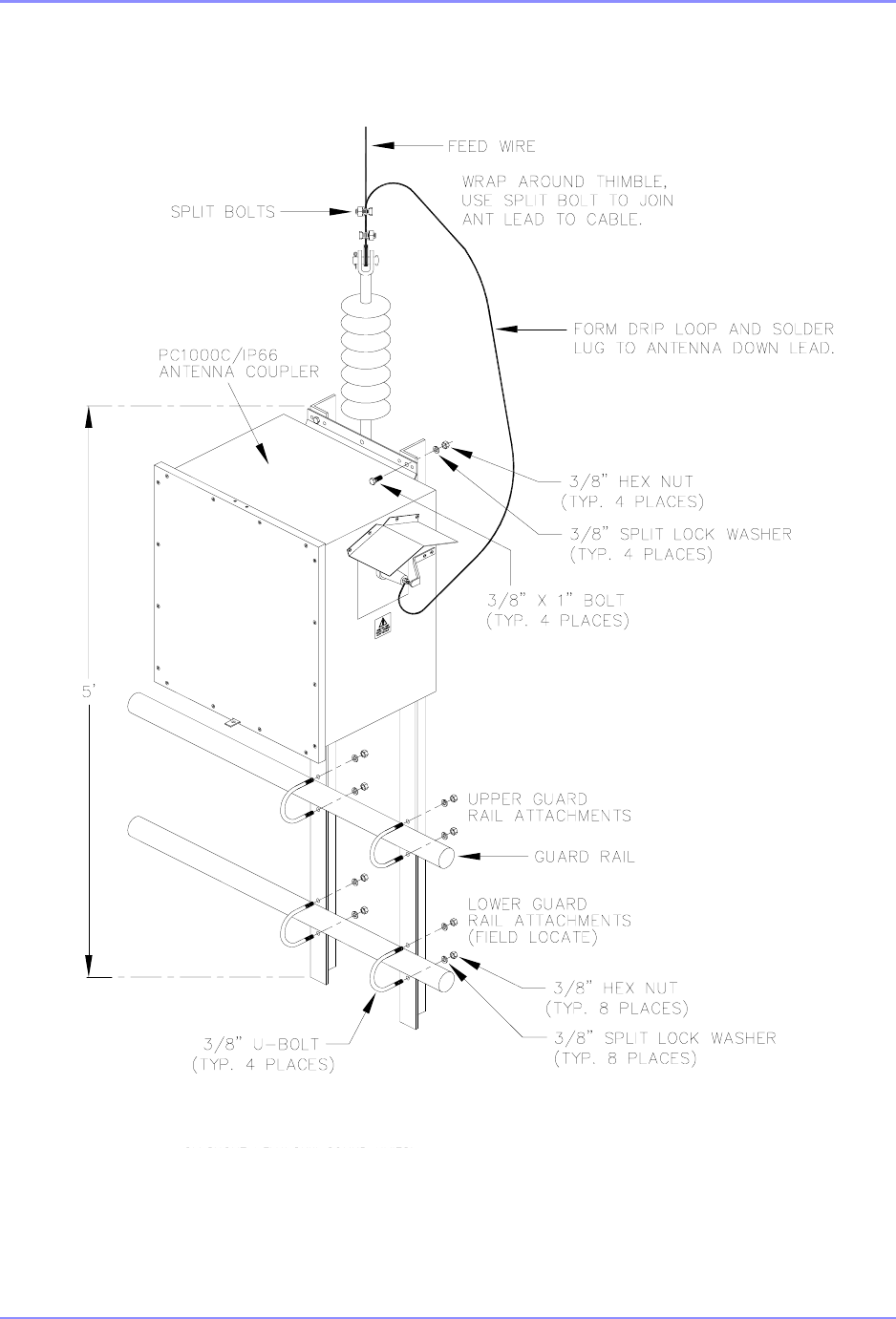
Figure 2-4. SE Transmitter mounted on offshore platform Guard Rails.....................................2-4
Figure 2-5. PC1000C/IP66 Coupler Mounted on Guard Rails................................................... 2-5
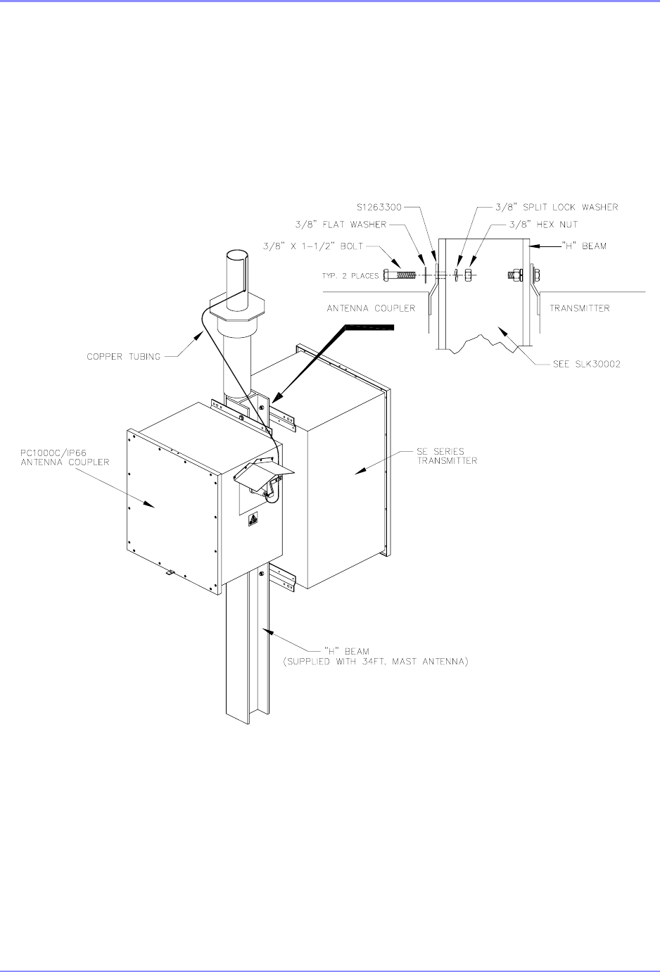
Figure 2-6. SE Transmitter and Coupler Mounted on Steel “H” Beam ...................................... 2-6
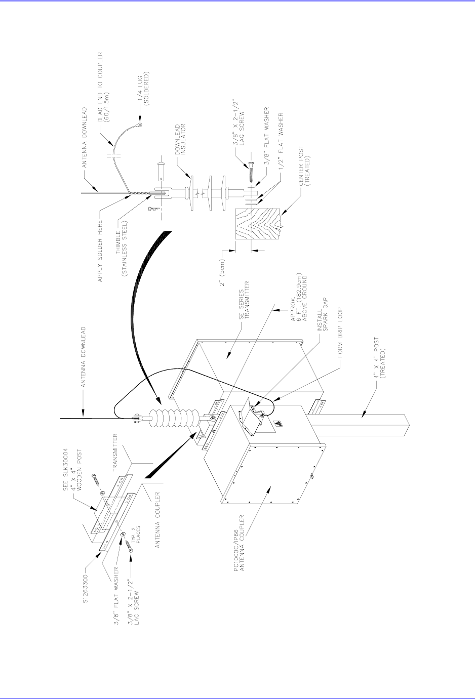
Figure 2-7. SETransmitter and Coupler Mounted on Wooden Post ..........................................2-7
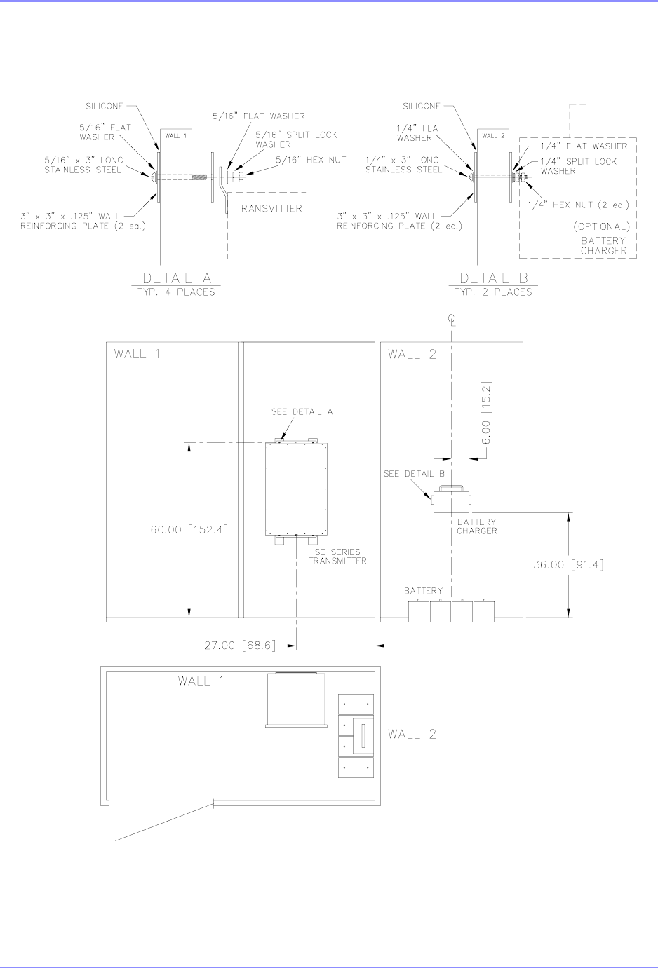
Figure 2-8. SE Transmitter Mounted in Shelter .........................................................................2-8
Figure 3-1. SE Series User Interface Diagram, Method 1 ......................................................... 3-2
Figure 3-2. SE Series User Interface Diagram, Method 2 ......................................................... 3-3
Figure 3-3. System Ground - Enclosure Mount ......................................................................... 3-4
Figure 3-4. Conduits Access Holes............................................................................................ 3-6
Figure 3-5. Conduit Connection Diagram .................................................................................. 3-7
Figure 3-6. SE Transmitter Wire Detail...................................................................................... 3-8
Figure 3-7. SE Series System Interconnect............................................................................... 3-9
Figure 4-1. SE Master Control Panel.........................................................................................4-1
Figure 5-1. Web GUI Main Window (Dual system)....................................................................5-3
Figure 5-2. Web GUI Main Window (Single system) .................................................................5-5
Figure 6-1. Primary Transmitter Window ...................................................................................6-3
Figure 6-2. Web GUI Transmitter Setup Window ...................................................................... 6-5
Figure 6-3. SE Transmitter Drawer Diagram .............................................................................6-6
Figure 6-4. Web GUI Transmitter Calibration Window............................................................. 6-12
Figure 6-5. Web GUI Network IP Configuration Window......................................................... 6-16
Figure 6-6. Web GUI Time & Date Setting Window................................................................. 6-17
Figure 6-7. Web GUI Location Site Window ............................................................................6-18
Figure 7-1. Morse code Identifier detail ..................................................................................... 7-6
Figure 9-1. Coupler Access Panel ............................................................................................. 9-2
Figure 9-2. PC1000C/3 Coupler cable connection ....................................................................9-4

SOUTHERN AVIONICS COMPANY
SE125 Transmitter 2Figures
Figure 9-3. Mast Antenna Tuned For 190-415 kHz ...................................................................9-7
Figure 9-4. Mast Antenna Tuned For 415-625 kHz ...................................................................9-8
Figure 9-5. DPA/50 Foot Guyed Mast Antenna .........................................................................9-9
Figure 9-6. Symmetrical “T” Antenna....................................................................................... 9-10
Figure 9-7. Whip Antenna Tuned For 283-330 kHz................................................................. 9-11
Figure 9-8. Whip Antenna Tuned For 360-600 kHz................................................................. 9-12
Figure 9-9. Whip Antenna Tuned For 547-1290 kHz............................................................... 9-13
Figure 9-10. Whip Antenna Tuned For 814-1700 kHz............................................................. 9-14
Figure 11-1. SE Conduit Connection Diagram......................................................................... 11-2
Figure 12-1. Audio Block Diagram...........................................................................................12-3
Figure 12-2. Ethernet Serial Server Installation Diagram ........................................................ 12-4
Figure 12-3. Ethernet to Land line Dial-Up ..............................................................................12-9
Figure 12-4. Multi-Mode Ethernet to Fiber Optics Converter................................................. 12-16
Figure 12-5. Leased Line Modem..........................................................................................12-24
Figure 12-6. Ethernet Extender.............................................................................................. 12-34
Figure 12-7. Ethernet Radio link detail...................................................................................12-37
Figure 12-8. Internal Battery Charger .................................................................................... 12-46
Figure 12-9. Internal Battery Charger connection..................................................................12-47
Figure 12-10. Internal 50 Ohm Dummy Load ........................................................................ 12-50
SOUTHERN AVIONICS COMPANY
SE125 Installation and Setup 1-1
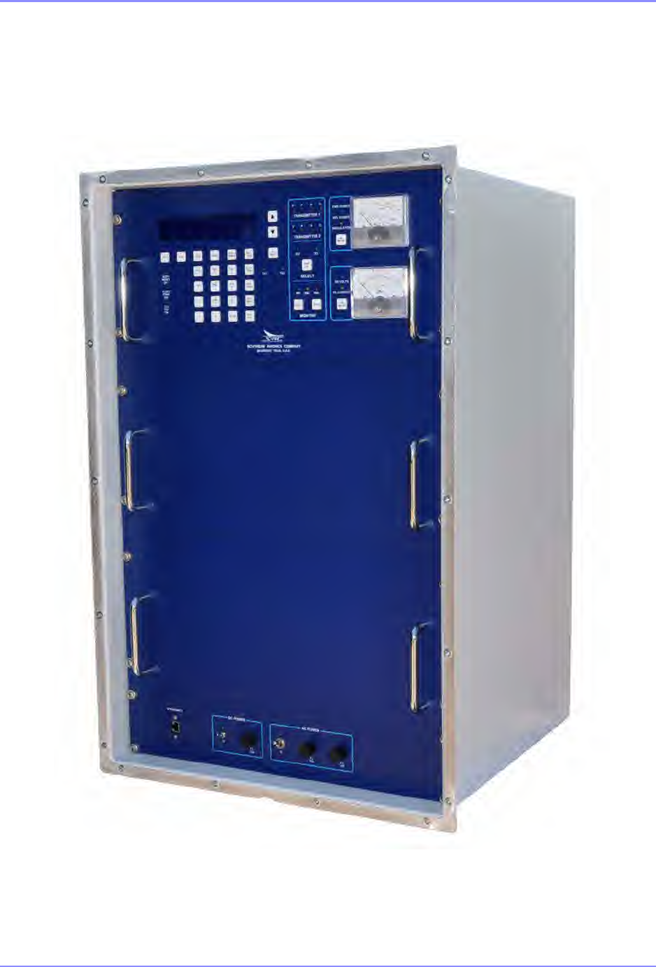
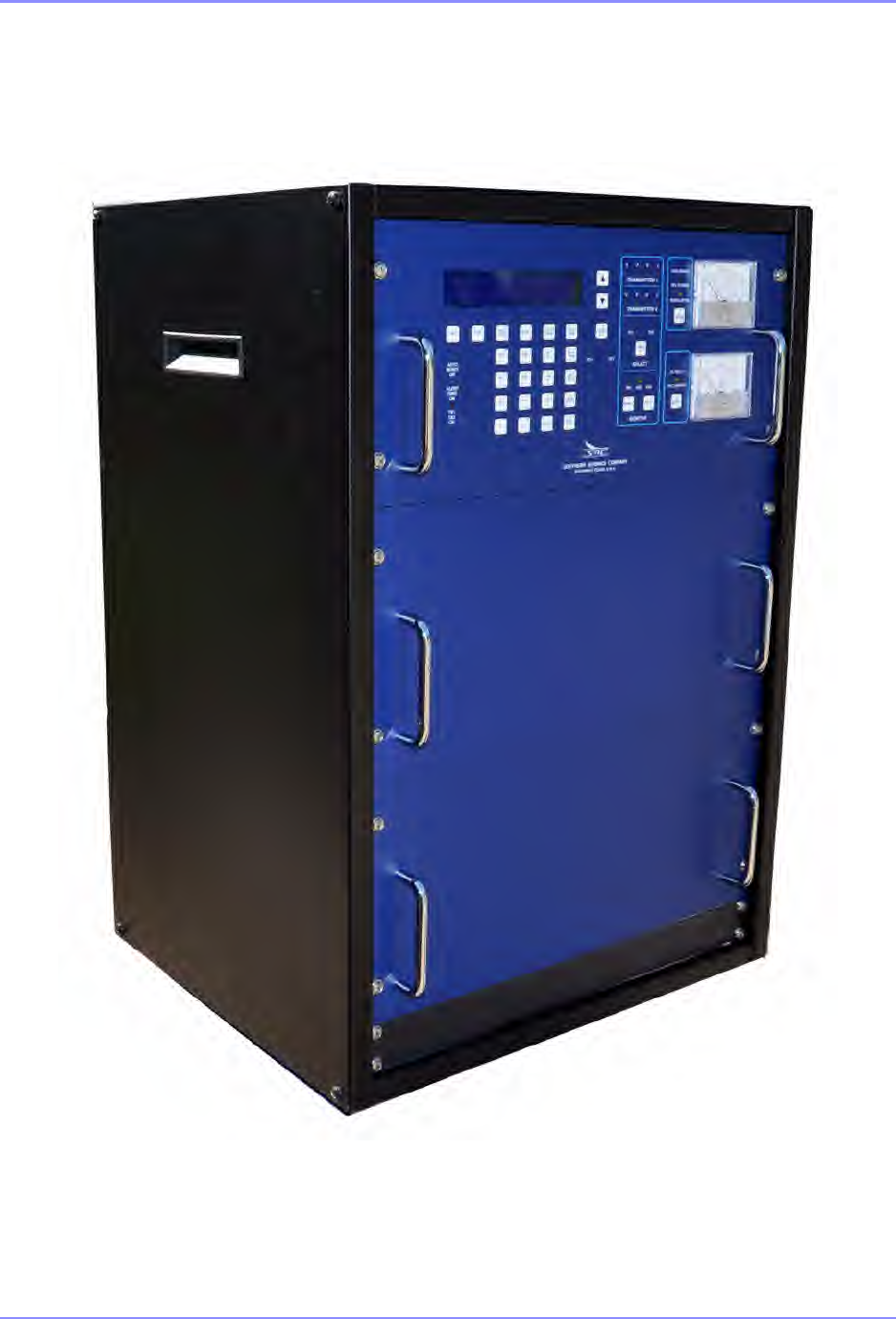
SE 125 Dual Transmitter in IP66 enclosure
SOUTHERN AVIONICS COMPANY
SE125 Installation and Setup1-2
SE 125 Dual Transmitter in rack cabinet
SOUTHERN AVIONICS COMPANY
SE125 Installation and Setup 1-3
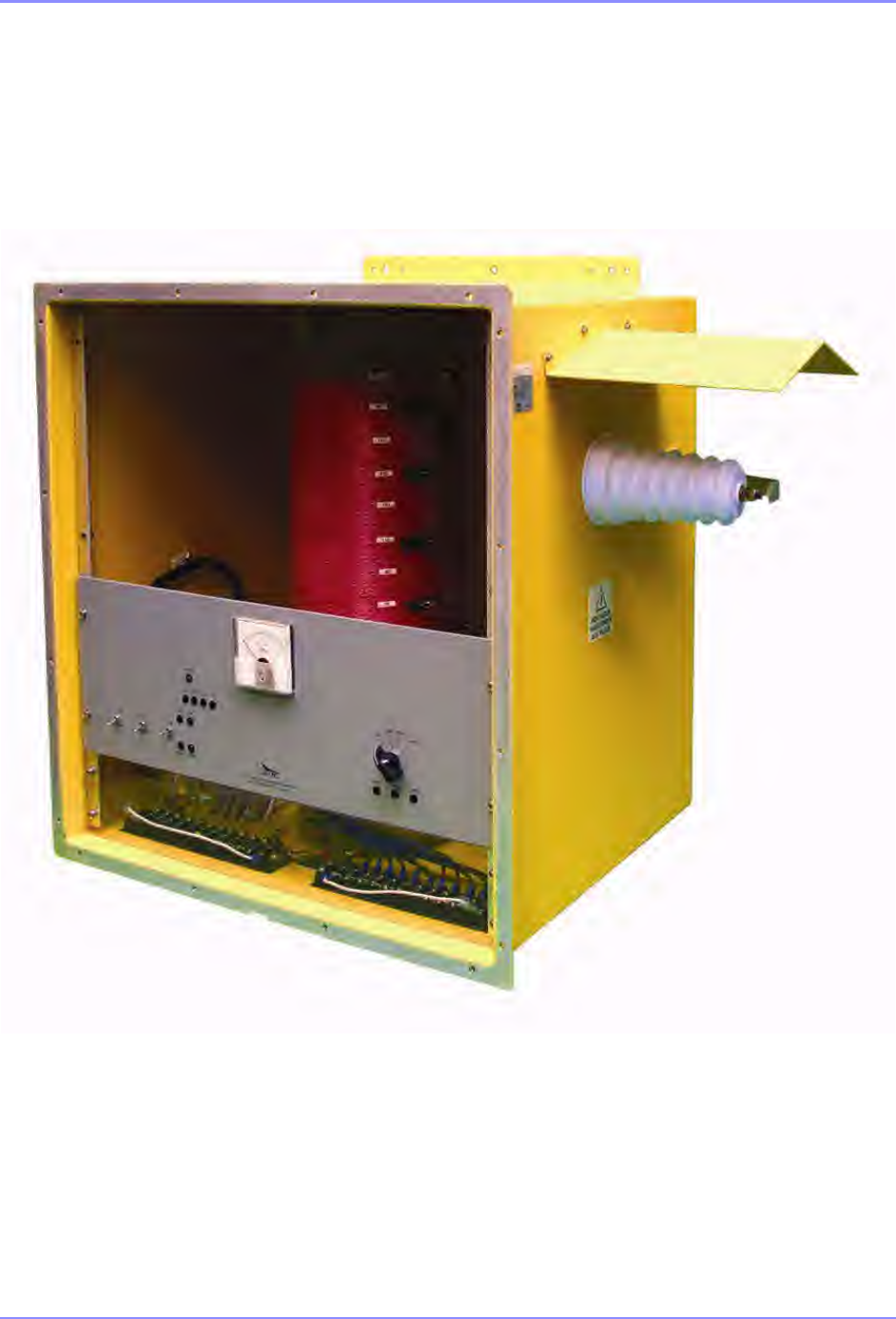
PC1000C/3 Antenna Tuning Unit in IP66 enclosure
SOUTHERN AVIONICS COMPANY
SE125 Installation and Setup1-4
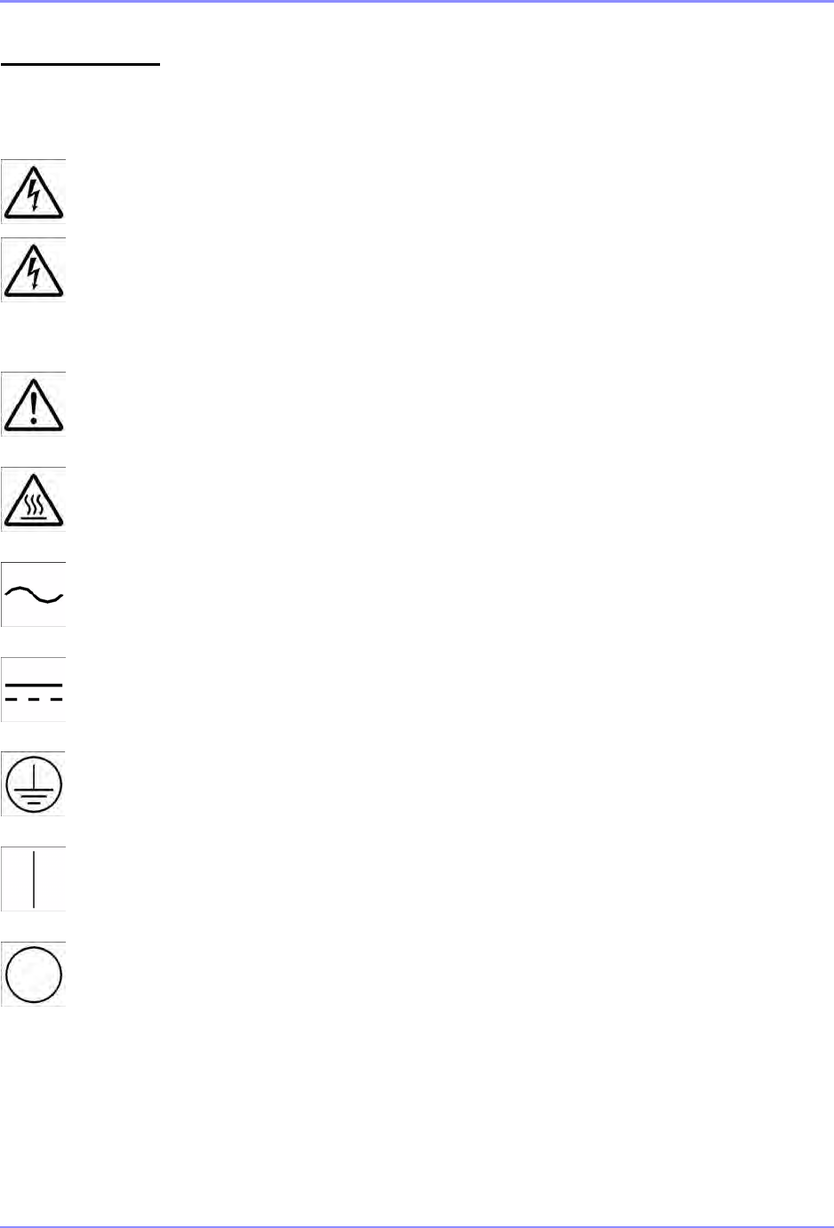
Safety Symbols Become familiar with the safety symbols presented in this section.
These symbols will alert you to safety hazards and conditions that
may result in personal injury, death, or property and equipment
damage.
WARNING: Electric shock hazard, high voltages capable of causing
personpersonal injury or death.
WARNING: Red lightning flash: High reactive voltages present capable of causing
personal injury.
HIGH VOLTAGE
GENERAL WARNING: See Installation Manual before proceeding
CAUTION: Heat hazard – allow heated components to cool before handling
Alternating Current
Direct Current
Protective Earth conductor or connection
ON (power switch)
OFF (power switch)

SOUTHERN AVIONICS COMPANY
SE125 Installation and Setup 1-5
ACRONYMS & ABBREVIATIONS
A ampere
AC alternating current
AGC automatic gain control
AGL above ground level
AM amplitude modulation
ANT antenna
ATU antenna tuning unit
AUTO automatic
AWG American wire gauge
AWOS automated weather observing system
BATCHG +/- battery charger +/-
BTRY +/- battery +/-
BNC Bayonet Neill-Concelman
BOM bill of materials
CARR carrier
CD compact disc
COM communication
CONT continuous
CPU central processing unit
dBm decibel referenced to 1 milliwatt
DMM digital multi meter

SOUTHERN AVIONICS COMPANY
SE125 Installation and Setup1-6
DC direct current
DCAD DC automatic disconnect
DDS direct digital synthesis
ESD electrostatic discharge
FET field effect transistor
FWD forward
GND ground
HV high voltage
HZ Hertz
ID identifier
IDENT identifier
I/O input/output
LCD liquid crystal display
LED light emitting diode
LINE 1/ LINE 2 ac input voltage
LOTO lock out/tag out
LV low voltage
LVPS low voltage power supply
MOD modulation
MSEC millisecond
MSK minimum shift keyed
N/A “not applicable, not available”
NDB non-directional beacon
NVRAM non-volatile random access memory

SOUTHERN AVIONICS COMPANY
SE125 Installation and Setup 1-7
PA power amplifier
PAI power amplifier current
PC personal computer
PCB printed circuit board
PE GND protective earth ground
PPM parts per million
PWM pulse width modulation
RAM random access memory
REFL reflected
RF radio frequency
RG radio grade
ROM read only memory
RS recommended standard
SAC Southern Avionics Company
SE current digital series transmitter
sd shutdown
SPA switching power amplifier
TX transmit
V “volts, voltage”
VAC alternating current voltage
VDC direct current voltage
VMAX maximum voltage
VMIN minimum voltage

SOUTHERN AVIONICS COMPANY
SE125 Installation and Setup1-8
VPP volts peak-to-peak
VSWR voltage standing wave ratio

SOUTHERN AVIONICS COMPANY
SE125 Installation and Setup 1-9
PREFACE
This document is intended to serve as a guide to the user in the installation and setup of
Southern Avionics Company's (SAC) "SE Series" of Non-Directional Beacons (NDB).
Instructions for the installation of the transmitter system and coupler include suggested
techniques for various mounting configurations of both the transmitter and the coupler, point to
point interconnection instructions and diagrams for all associated cabling and wiring,
recommended cable/wire selection, and optional solutions for preventing dust/water ingress at
cable entry of the coupler enclosure.
Additionally, a detailed step-by-step procedure is offered to guide the user through the Site
Configuration, the checkout and calibration of the various operating parameters, and finally,
placing the system in operation.

SOUTHERN AVIONICS COMPANY
SE125 Installation and Setup1-10
This page intentionally left blank.

SOUTHERN AVIONICS COMPANY
SE125 Installation and Setup 1-11Introduction
1Introduction
The SE Series transmitters are computer controlled systems designed around an embedded
microprocessor. These systems are capable of remote monitoring and maintenance via Ethernet
(optional).
All aspects of transmitter setup and operation, with the exception of main power application,
come under the direct control of the Controller/Monitor. Setup and control of the Transmitter is
performed at the local control panel or by a separate personal computer (PC)/laptop connected
locally or remotely via Ethernet. Options are available for control remotely using phone lines or
other carrier, which can handle leased line or dial up modems. The PC or laptop uses custom
software to generate a graphical user interface (Web Watch) which allows monitoring of system
parameters and provides setup and control of the following:
•Direct Digital Synthesis (DDS) generated RF carrier frequency and Audio Tone
Frequencies
•Identifier Morse Code (up to eight (8) characters or numbers)
•Standard alarms, view and reset
•Additional fault handling based on multipoint voltage, current, and temperature monitoring
•Transfer criteria (dual transmitter only)
•Power levels
•Modulation levels
An optional Remote Control Unit (RCU) is available which uses RS-485 communication lines
between it and the transmitter. The RCU allows full monitoring and basic control of the
transmitter from up to 4000ft (1220m) away.

SOUTHERN AVIONICS COMPANY
SE125 Installation and Setup1-12 Introduction
1.1 General Specifications
•Frequency Range - continuously variable from 190 - 1800 kHz
•Frequency Tolerance - 5ppm standard (1ppm optional) Temperature Controlled Crystal
Oscillator (TCXO)
•RF Power Output - 10 to 125 Watts RF Output Amplitude Modulated 0-95%; power and
modulation level adjustable from local keypad
•Central Processor - Renesas M16C 16 bit processor operating at 20 MHz
•Residual Noise and Hum Levels - more than 40dB below the carrier level at 95%
modulation
•Spurious Emission - using the matching antenna coupler, radiated harmonics are more
than 70dB below the carrier
•Type of Emission - NON, A2A, A3E (optional) or any combination; GID (with optional
GPS beacon modulator)
•Modulation - NON produces blank carrier with no modulation; A3E Amplitude Modulated
voice carrier from audio input line; A2A continuous or keyed tone modulation available
with internal 400 Hz or 1020 Hz tone ; Morse Code operation at a speed of 5-15 WPM.
Modulation frequency is user-programmable.
•Power Amplification - Class D using power MOSFETS
•Audio Line Input - balanced, 600 Ohms, -25 to 0dBm
•Audio Distortion - less then 1% @ 95% modulation
•Antenna Connection - Type N female output standard
•Monitoring - monitoring firmware will shutdown the transmitter under the following
conditions:
loss of tone
continuous tone
reduced modulation level
reduced power output below 3dB
increased power output above 2dB
VSWR rise above a preset level
loss of heartbeat pulse from Renesas processor
incorrect Morse code identification

SOUTHERN AVIONICS COMPANY
SE125 Installation and Setup 1-13Introduction
With a dual transmitter, the front panel processor initiates a transmitter transfer, when a
fault condition occurs.
•Built-in Test Equipment (BITE) - Front panel or remote monitoring (via Web Watch) of
critical parameters within transmitter modules covers all stages of operation; built in
frequency monitor maintains proper frequency operation
•Display - 40 character by 4 line LCD with white characters on a blue background
•User Interface - power control keypad with numeric and functional membrane switches
for ease of data entry and control without the need of a computer
•Metering - dual front panel analog meters for forward and reflected power, modulation
percentage, final PA voltage and current
•Interface - barrier block connector for user selectable RS232/RS485 standard for
Remote Control Unit interface.
•Optional RJ45 Ethernet Connection - Ethernet can be configured either hard wired IP
address or server set using DHCP (TCP/IP or UDP). Full control and monitoring
available through IP connection. Internal firmware supports Ethernet interface. No
additional user software required.
•Power Input - 100-264VAC, 47-63Hz, or 48VDC
•Environmental - ambient temperature -50ºC to +55ºC, relative humidity 100% non-
condensing.
1.2 Model SE125 General Description
The SE series non-directional beacon is a microprocessor controlled Amplitude Modulated (AM)
transmitter with output power adjustable from 10 - 125 Watts. The radio frequency (RF) section uses
field effect transistor (FET) switching technology in the power amplifier (PA), modulator, high voltage
(HV) and low voltage (LV) regulator modules resulting in a highly efficient system.
The front control panel utilizes membrane switches and an easy to view 40 line by 4 character
LCD with white characters on a blue background. Front panel controls include Desired Carrier
Frequency, Tone Frequency, Call Sign/Identifier, Output Power, Modulation Level, Main
Transmitter select, Mode of Operation, Monitor Enable, and controls for monitoring critical
transmitter parameters and test modes.
The Master Control and Transmitter Control sections utilize the Renesas M16C/29 microprocessor,
which was designed specifically for efficient embedded systems. The Transmitter Control utilizes
modern direct digital synthesis (DDS) technology to create the precision audio and radio frequencies
needed by the RF section. Beacon operation is program controlled and monitored. Most of the
operational parameters are user-definable thus facilitating customized equipment configurations.
Using an Ethernet connection, the user has complete control of the SE transmitter. In addition, a
personal computer (PC) running an Internet Browser and connected to the Transmitter’s IP address
can communicate with, configure, and monitor the system.

SOUTHERN AVIONICS COMPANY
SE125 Installation and Setup1-14 Introduction
All standard fault conditions such a Low Power, No-Tone, VSWR, and Continuous Tone are
monitored. Additional fault conditions designed to protect the equipment are reported via an interrupt
request (IRQ) to trigger an immediate response from the controller.
Other important system parameters such as PA current, PA voltage, AC and DC current and voltage,
high voltage, and RF current are also monitored.
RF frequency is monitored with an independent counter and is correctable beyond the stated base
frequency accuracy. RF Power and Modulation percentage readings are also corrected to yield near
test equipment quality measurements.
System configuration includes discreet control Morse Code entry as well a maximum of eight (8)
character ID sequences. Dual system operation is available in a totally redundant system including
two independent Transmitter Controllers, RF sections and Power Supplies.
Optional emergency battery power is supported with battery voltage and both charge and discharge
current being monitored. The DC automatic disconnect (DCAD) feature, which protects the battery
stack from excessive discharge, is user-definable, and allows the system to be optimized for whatever
battery type the user chooses.
Optional automated weather observing system (AWOS) voice operation is supported with
automatic gain control (AGC) ensuring proper operation over a wide range of user inputs. Band
pass filtering limits the audio output to satisfy Federal Communications Commission (FCC)
bandwidth requirements.
The transmitter is provided in an IP66 rated enclosure or a 19 inch rack mountable
configuration.
Qualifications: Transmitter is designed to meet applicable requirements of International Civil
Aviation Organization (ICAO), Federal Communications Commission (FCC), Federal Aviation
Authority (FAA), Transport Canada, United Kingdom's Civil Aviation Authority (CAA), and the
European Commission (CE).
SOUTHERN AVIONICS COMPANY
SE125 Installation and Setup 1-15Introduction
1.3 SE Series Transmitter Specifications
1.3.1 Maximum Input Current Requirements
The maximum continuous AC and DC current requirements are tabulated in Table 1-1. and
Table 1-2. The main AC and DC power breakers selected should be rated accordingly and, in the
case of the AC breaker, incorporate appropriate delay.
1.3.1.1 Single Transmitter current
The maximum current is based on a single transmitter running at 125 Watts power and 100%
continuous modulation. Fault protection circuitry will shutdown the system if these are exceeded.
Table 1-1. Single Transmitter MAX Input Current Requirements (Amps)
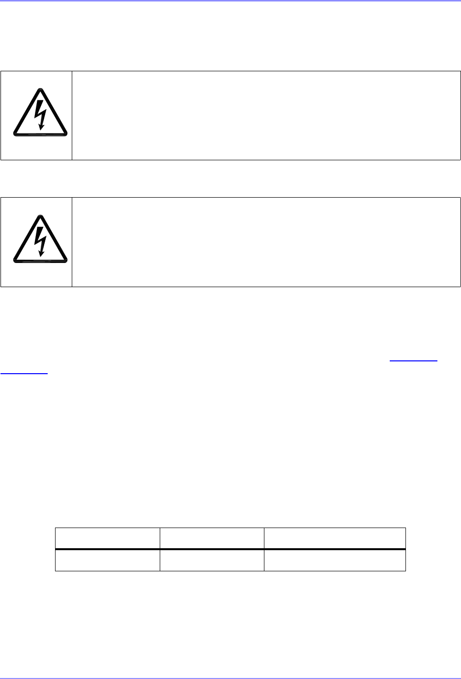
Danger: Shock Hazard. Serious injury or death from electrical
shock is possible when handling electrical power input wiring. Ensure AC
and DC main breakers are open. Observe any applicable standards
regarding Logout/Tagout (LOTO) procedures.
Danger: Shock Hazard. Residual voltage may be present accross
AC Voltage input terminals for a short time after removal of input voltage.
SYSTEM 100-264 VAC BATTERY (38-52 VDC)
SE125 3.2A 7.6A

SOUTHERN AVIONICS COMPANY
SE125 Installation and Setup1-16 Introduction
1.3.1.2 Dual Transmitter current
The maximum current is based on both transmitters running simultaneously (AC only) at 125
Watts and 100% continuous modulation. Fault protection circuitry will shutdown the system if
these are exceeded.
Table 1-2. Dual Transmitter MAX Input Current Requirements (Amps)
1.3.2 RF Specifications
•Type of Emission - NON, A2A, A3E (optional) or any combination; GID (with optional
GPS beacon modulator)
•Frequency Range - continuously variable from 190 - 650 kHz or optionally 650-1250kHz
and 1500-1800kHz
•Frequency Stability - better than 5ppm from -20ºC to +70ºC
•RF Power Output - continuously variable from 10 - 125 Watts
•PA Efficiency - better than 90%
•Tone Modulation Frequency - user definable 400 or 1020 Hz
•Tone Modulation Depth - user definable from 0 - 95%; modulation tracks carrier power
changes
•Identification Keying - any combination of Morse code letters or numerals (8 character
maximum length)
•Spurious Emission - harmonics are more than 65dB below the 125 Watt carrier
(measured at a dummy antenna)
•Residual Noise and Hum Levels - more than 40dB below the carrier level at 95%
modulation
1.3.3 Transmitter Environment Tolerance
Continuous unattended operation in the following environments:
•ambient temperature, -40°C to +55°C
•relative humidity, 0-100% non-condensing
SYSTEM 100-264 VAC BATTERY (38-52VDC)
DC BACKUP NOT INTENDED
FOR TEST MODE OPERATION
SE125 6.0A 14.8

SOUTHERN AVIONICS COMPANY
SE125 Installation and Setup 1-17Introduction
•high salinity (as encountered in offshore conditions)
•operation up to 10,000ft (3050m)
1.3.4 Circuit Protection (hardware)
•input AC fusing
•input DC fusing
•ATU 12VDC fusing
•Low voltage/High voltage Power Supply over - current shutdown
•modulator automatic over-current shutdown
•RF PA automatic over-current shutdown
•hardware triggered fault interrupts for:
1.3.5 Total Redundancy (Dual Operation)
•two independent transmitter sections with independent transmitter controller sections with
separate AC Power suppies, Power Amplifiers, Modulators, RF Filters and LV/HV power
supplies.
•Monitor Control communicates and controls both Transmitters via I2C bus.
•automatic transferring.
1.3.6 Active Monitoring and Control
Transmitter shutdown (single) or transfer (dual) conditions:
HVPS_HIGH/LOW SIDE High voltage power supply
high/low side current (overload)
PAI(F) Power amplifier over current
PWR_CTRL_I_OVLD Power control current (overload)
MOD_SHTDN Modulator shutdown
MOD_I_OVLD Modulator current overload

SOUTHERN AVIONICS COMPANY
SE125 Installation and Setup1-18 Introduction
•loss of modulation (carrier only, duration = 30 sec)
•low modulation (70%, duration = 30 sec)
•continuous modulation (no keying, duration = 30 sec)
•low power (50%, duration = 30 sec)
•high power (120%, duration = 30 sec)
•VSWR (>2.62:1, duration = 2 sec)
•under-temperature (<-40°C, duration = 120 sec)
•over-temperature (>70°C, duration = 120 sec)
•ID sequence error (immediate action)
•over/under-frequency (>100Hz, duration = 120 sec)
1.3.7 Passive Monitoring
•battery charge and discharge rates
•antenna current
1.3.8 Local PC Control
Local PC control is established using a Desktop or Laptop personal computer (PC) running Vista,
XP or Windows 7 running an Internet browser connected to the Ethernet port located on the front
panel of the SE Transmitter.
1.3.9 Master Control Panel
Displays the following without the need of a PC:
•selected transmitter
•RF forward power
•RF reflected power
•modulation percent
•PA voltage
•PA current
•RF frequency
•AF frequency

SOUTHERN AVIONICS COMPANY
SE125 Installation and Setup 1-19Introduction
•power select status (transmitter activated)
•primary transmitter selected
•operational mode (Carrier/Ident/Continuous)
•shutdown alarms
•monitor disabled
Controls the following without the need of a PC:
•displayed transmitter selection
•RF forward power, RF reflected power, or modulation % display
•PA voltage, PA temperature, or PA current display
•RF frequency or AF frequency display
•primary transmitter selection
•operational mode (Carrier/Ident/Continuous) selection
•monitor functions (alarms) disable
•simultaneous test mode operation for both transmitters (dual only)
1.3.10 Remote Operation (optional)
•Allows full monitoring and basic control over the existing transmitter
•All readings at the transmitter are available at the RCU via RS-485 at a distance of up to
4,000ft (1,220m)
•Selection of Primary Transmitter can be made and the system Powered Up or Down. All
Built-In Test Equipment data is displayed on the LCD screen
•Indications for Primary, Secondary and Fail are provided, as well as those for ICAO
Annex 10 Chapter 3.4 shutdown requirements
•Power provided by external 12VDC wall-mounted power supply or customer’s 12VDC
source
1.3.11 AWOS Operation (optional A3E mode)
Optional PCB enabling external voice modulation and featuring:
•automatic gain control (prevents over-modulation) capture, -30dBm to +5dBm
•automatic keyer tone modulation level reduction

SOUTHERN AVIONICS COMPANY
SE125 Installation and Setup1-20 Introduction
•band pass filtering, 300 - 3000 Hz
•nominal user input of -17dBm @ 600 Ohms for 95% modulation
1.4 Equipment Weights
SE Series Single Transmitter (SLF33300)
with IP66 enclosure 59 lbs.
SE Series Dual Transmitter (SLF33400)
with IP66 enclosure 99 lbs.
PC1000 / IP66 Antenna Coupler (SLF20050/C3) 39 lbs.
PC3000 Antenna Coupler (SLF20020) 62 lbs.
SOUTHERN AVIONICS COMPANY
SE125 Installation and Setup 1-21Introduction
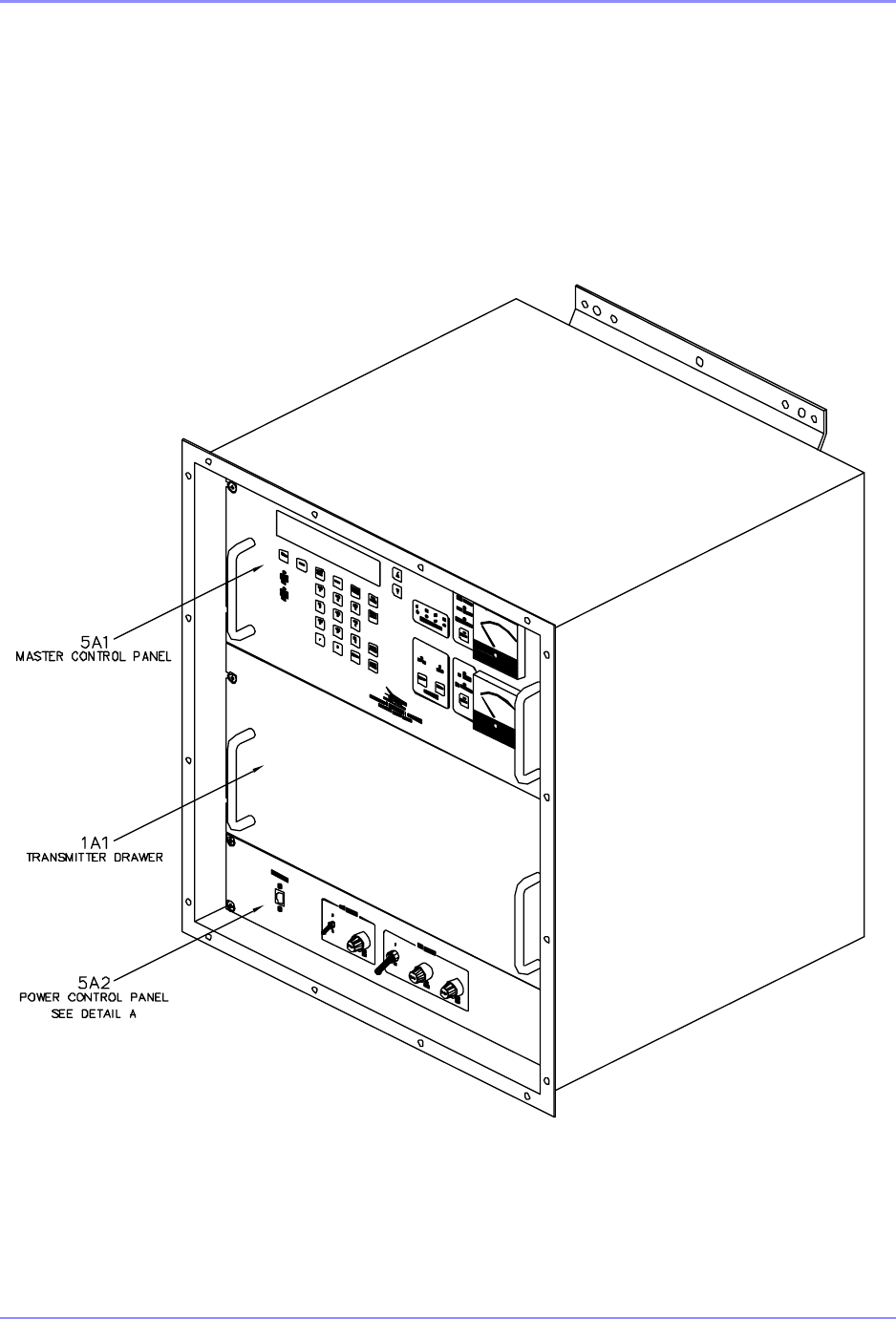
1.5 Equipment Appearance
SDF33300 Rev A
Figure 1-1. SE125 Single Transmitter Diagram
SOUTHERN AVIONICS COMPANY
SE125 Installation and Setup1-22 Introduction
1.6 Equipment Exterior Details
SDF33300 Rev A
Figure 1-2. SE125 Single Transmitter Enclosure Detail
SOUTHERN AVIONICS COMPANY
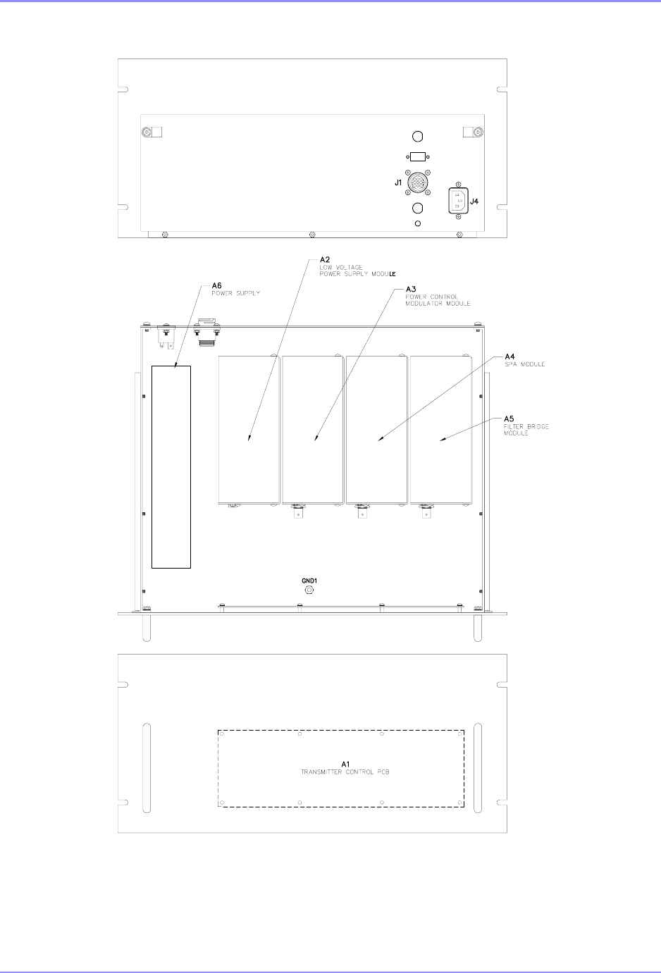
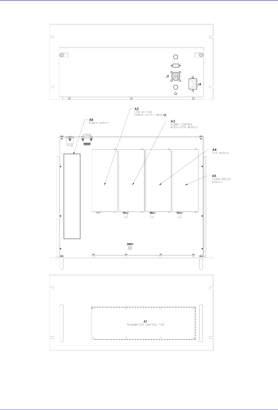
SE125 Installation and Setup 1-23Introduction
SDE33200 Rev 1
Figure 1-3. SE125 Single Transmitter 1A1 Detail
SOUTHERN AVIONICS COMPANY
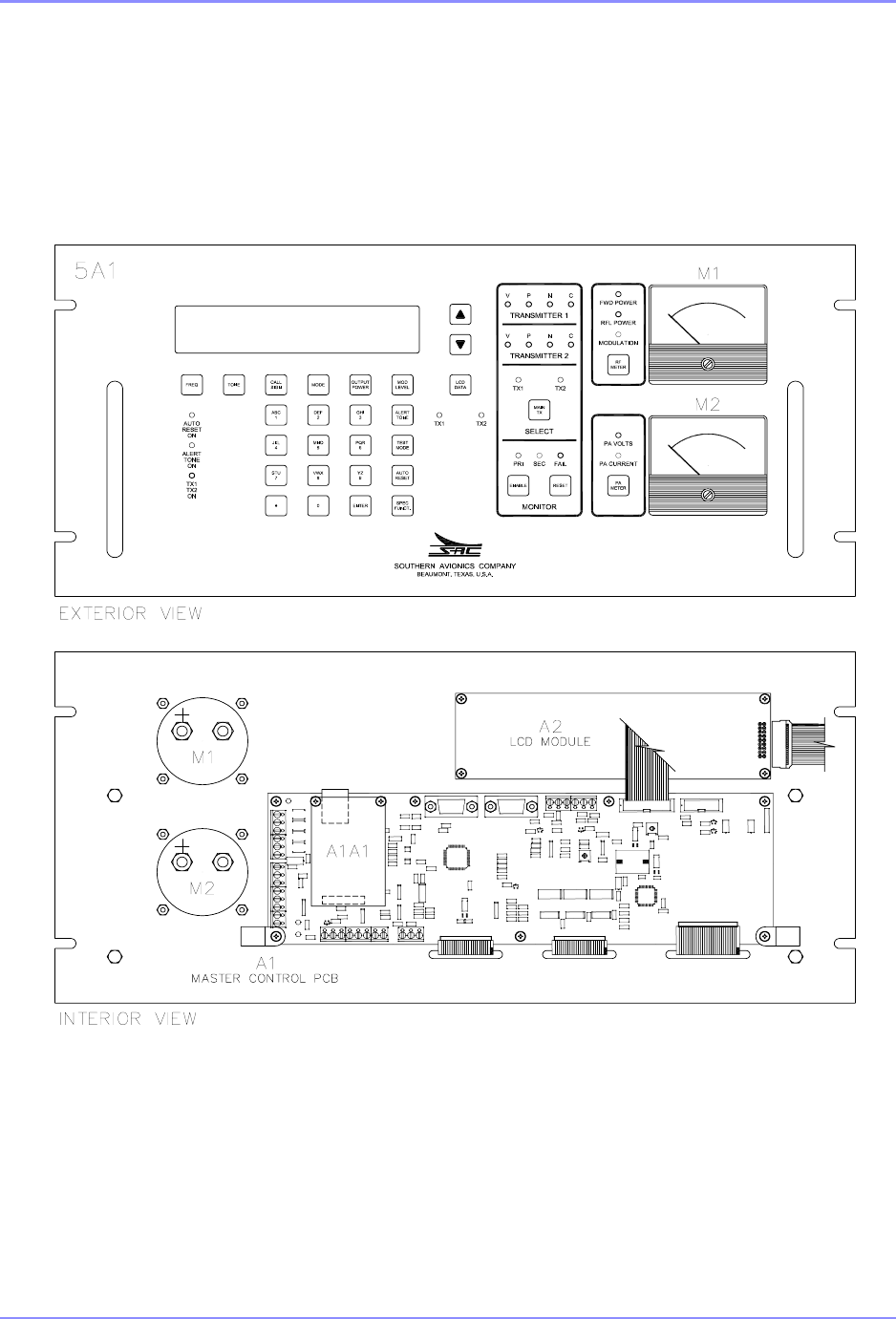
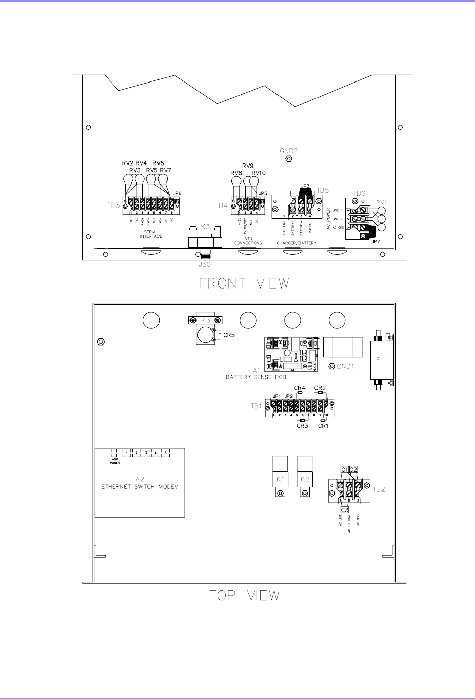
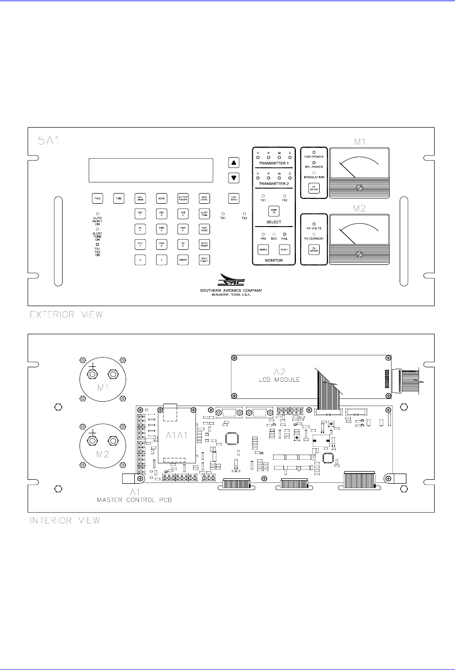
SE125 Installation and Setup1-24 Introduction
SDE33010 Rev B
Figure 1-4. SE125 Single Transmitter 5A1 Detail
SOUTHERN AVIONICS COMPANY
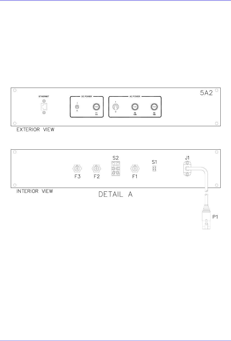
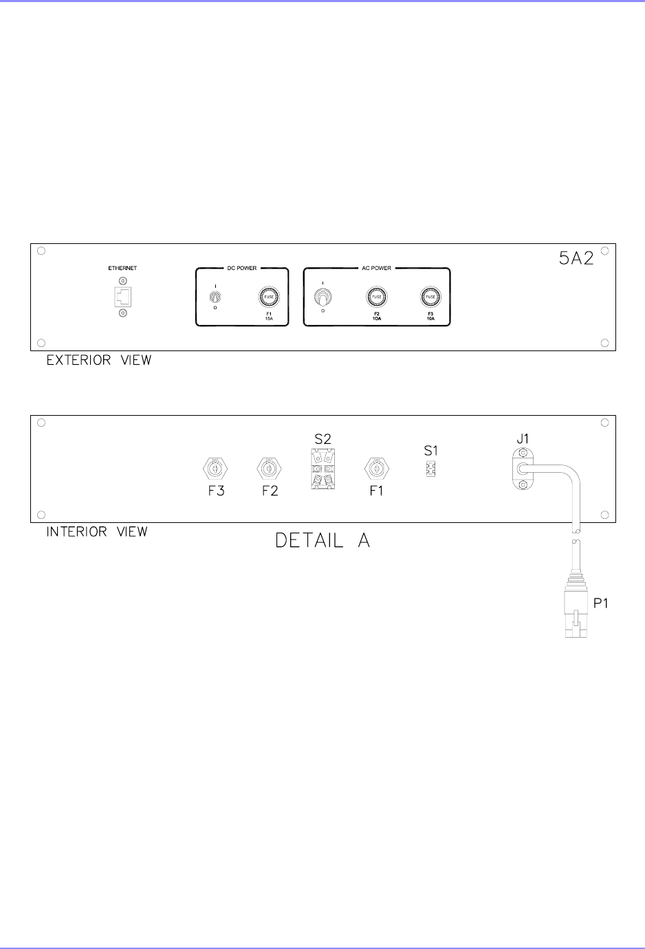
SE125 Installation and Setup 1-25Introduction
SDF33400 Rev 1
Figure 1-5. SE125 Single Transmitter 5A2 Detail

SOUTHERN AVIONICS COMPANY
SE125 Installation and Setup1-26 Introduction
This page intentionally left blank.

SOUTHERN AVIONICS COMPANY
SE125 Installation and Setup 1-27Introduction
1.7 Parts list - SLF33300 Transmitter, SE125 Single
REF
DES QTY PART
NUMBER DESCRIPTION
A1 1SLP45601 BATTERY SENSE VOLTAGE REGULATOR (EREG)
A2 1 9S900033 SWITCH, ETHERNET 5-PORT (OPTIONAL)
K1 19R190070 RELAY; SPDT, AUTOMOTIVE PLUG-IN 12V
FL1 1 9F345007 FILTER; LINE AC POWER (OPTIONAL)
RV1 1SLW33006 ASSEMBLY SURGE SURPRESSOR
1A1 1 SLE33100 TRANSMITTER DRAWER ASSEMBLY
1A1A1 1SLP45500 TRANSMITTER CONTROL PRINTED CIRCUIT BOARD
1A1A2 1 SLE45400 LOW VOLTAGE POWER SUPPLY MODULE
1A1A3 1SLE45100 POWER CONTROL MODULATOR MODULE
1A1A4 1 SLE45000 SWITCHING POWER AMPLIFIER MODULE
1A1A5 1SLE45200 FILTER/BRIDGE STANDARD BAND MODULE
1A1A6 1 9P690350 POWER SUPPLY, PSU-350
2 1 COUPLER
31 ANTENNA
5A1 1SLM33000 MASTER CONTROL PANEL
5A1A1 1 SLP43300 MASTER CONTROL PRINTED CIRCUIT BOARD
5A1A1A1 19C583005 CONVERTER; SERIAL TO ETHERNET (OPTIONAL)
5A1A2 1 9L100000 LIQUID CRYSTAL DISPLAY MODULE
5A1M1 19M190009 METER; 2.5IN, 0-1MA RF POWER
5A1M2 1 9M190028 METER; 2.5IN, 0-1MA, PA
5A2 1SLM33003 POWER CONTROL PANEL
5A2S1 1 9S901004 SWITCH, SPDT PC
5A2S2 19S900005 SWITCH, DPST, 15A/120V, 10A/250V
5A2F1 1 9F830150 FUSE, 15 AMP, 250V, FAST ACTING
5A2F2 19F830103 FUSE, 10 AMP, 250V, 3AB, SLO-BLO
5A2F3 1 9F830103 FUSE, 10 AMP, 250V, 3AB, SLO-BLO
1SLK33001 KIT, HARDWARE/INSTALLATION
1 SLF83301 LEASED LINE MODEM (OPTIONAL)
1SLF83303 MULTI-MODE EHTERNET TO FIBER OPTICS
CONVERTER 2KM (OPTIONAL)

SOUTHERN AVIONICS COMPANY
SE125 Installation and Setup1-28 Introduction
1 SLF83304 ETHERNET RADIO LINK (OPTIONAL)
1SLF83308 MULTI-MODE EHTERNET TO FIBER OPTICS
CONVERTER 20KM (OPTIONAL)
1 SLF83312 SE CE SINGLE (OPTIONAL)
1SLF83313 SE ETHERNET SINGLE (OPTIONAL)
1 SLF83314 ETHERNET TO LAND LINE DIALUP (OPTIONAL)
1SLF83315 ETHERNET EXTENDER(OPTIONAL)
1 SLF83320 BATTERY CHARGER (OPTIONAL)
1SLF83350 INTERNAL DUMMY LOAD (OPTIONAL)
1 SLE33089 REMOTE CONTROL PANEL SINGLE (OPTIONAL)
REF
DES QTY PART
NUMBER DESCRIPTION
SOUTHERN AVIONICS COMPANY
SE125 Installation and Setup 1-29Introduction
SDF33400 Rev 1
Figure 1-6. SE125 Dual Transmitter Diagram
SOUTHERN AVIONICS COMPANY
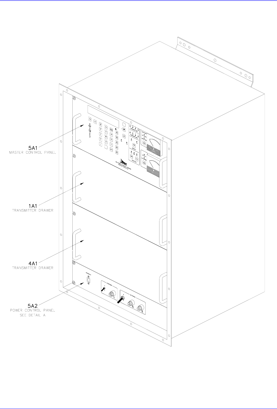
SE125 Installation and Setup1-30 Introduction
SDF33400 Rev A
Figure 1-7. SE125 Dual Transmitter Enclosure Detail
SOUTHERN AVIONICS COMPANY
SE125 Installation and Setup 1-31Introduction
SDE33200 Rev 1
Figure 1-8. SE125 Dual Transmitter 1A1 and 4A1 Detail
SOUTHERN AVIONICS COMPANY
SE125 Installation and Setup1-32 Introduction
SDE33010 Rev B
Figure 1-9. SE125 Dual Transmitter 5A1 Detail
SOUTHERN AVIONICS COMPANY
SE125 Installation and Setup 1-33Introduction
SDE33400 Rev 1
Figure 1-10. SE125 Dual Transmitter 5A2 Detail

SOUTHERN AVIONICS COMPANY
SE125 Installation and Setup1-34 Introduction
This page intentionally left blank.

SOUTHERN AVIONICS COMPANY
SE125 Installation and Setup 1-35Introduction
1.8 Parts list - SLF33400 Transmitter, SE125 Dual
REF
DES QTY PART NO. DESCRIPTION
A1 1SLP45601 BATTERY SENSE VOLTAGE REGULATOR (EREG)
A2 1 9S900033 SWITCH, ETHERNET 5-PORT (OPTIONAL)
K1 19R190070 RELAY; SPDT, AUTOMOTIVE PLUG-IN 12V
K2 1 9R190070 RELAY; SPDT, AUTOMOTIVE PLUG-IN 12V
K3 19R190075 RELAY; COAXIAL SPDT, 50 OHM, 1.5VDC TYPE N
FL1 1 9F345007 FILTER; LINE AC POWER (OPTIONAL)
1A1 1SLE33100 TRANSMITTER DRAWER ASSEMBLY
1A1A1 1 SLP45500 TRANSMITTER CONTROL PRINTED CIRCUIT BOARD
1A1A2 1SLE45400 LOW VOLTAGE POWER SUPPLY MODULE
1A1A3 1 SLE45100 POWER CONTROL MODULATOR MODULE
1A1A4 1SLE45000 SWITCHING POWER AMPLIFIER MODULE
1A1A5 1 SLE45200 FILTER/BRIDGE STANDARD BAND MODULE
1A1A6 19P690350 POWER SUPPLY, PSU-350
2 1 COUPLER
3 1 ANTENNA
4A1 1 SLE33100 TRANSMITTER DRAWER ASSEMBLY
4A1A1 1SLP45500 TRANSMITTER CONTROL PRINTED CIRCUIT BOARD
4A1A2 1 SLE45400 LOW VOLTAGE POWER SUPPLY MODULE
4A1A3 1SLE45100 POWER CONTROL MODULATOR MODULE
4A1A4 1 SLE45000 SWITCHING POWER AMPLIFIER MODULE
4A1A5 1SLE45200 FILTER/BRIDGE STANDARD BAND MODULE
4A1A6 1 9P690350 POWER SUPPLY, PSU-350
5A1 1SLM33000 MASTER CONTROL PANEL
5A1A1 1 SLP43300 MASTER CONTROL PRINTED CIRCUIT BOARD
5A1A1A1 19C583005 CONVERTER; SERIAL TO ETHERNET (OPTIONAL)
5A1A2 1 9L100000 LIQUID CRYSTAL DISPLAY MODULE
5A1M1 19M190009 METER; 2.5IN, 0-1 MADC RF POWER
5A1M2 1 9M190028 METER; 2.5IN, 0-1MA, PA
5A2 1SLM33003 POWER CONTROL PANEL
5A2S1 1 9S901004 SWITCH, SPDT PC

SOUTHERN AVIONICS COMPANY
SE125 Installation and Setup1-36 Introduction
5A2S2 19S900005 SWITCH, DPST, 15A/120V, 10A/250V
5A2F1 1 9F830150 FUSE, 15 AMP, 250V, FAST ACTING
5A2F2 19F830103 FUSE, 10 AMP, 250V, 3AB, SLO-BLO
5A2F3 1 9F830103 FUSE, 10 AMP, 250V, 3AB, SLO-BLO
1SLK33001 KIT, HARDWARE/INSTALLATION
1 SLF83301 LEASED LINE MODEM (OPTIONAL)
1SLF83303 MULTI-MODE EHTERNET TO FIBER OPTICS
CONVERTER 2KM (OPTIONAL)
1 SLF83304 ETHERNET RADIO LINK (OPTIONAL)
1SLF83308 MULTI-MODE EHTERNET TO FIBER OPTICS
CONVERTER 20KM (OPTIONAL)
1 SLF83310 SE CE DUAL (OPTIONAL)
1SLF83311 SE ETHERNET DUAL (OPTIONAL)
1 SLF83314 ETHERNET TO LAND LINE DIALUP (OPTIONAL)
1SLF83315 ETHERNET EXTENDER(OPTIONAL)
1 SLF83320 BATTERY CHARGER (OPTIONAL)
1SLF83350 INTERNAL DUMMY LOAD (OPTIONAL)
1 SLE33090 REMOTE CONTROL PANEL DUAL (OPTIONAL)
REF
DES QTY PART NO. DESCRIPTION
SOUTHERN AVIONICS COMPANY
SE125 Installation and Setup 2-1Equipment Dimensions and Mounting
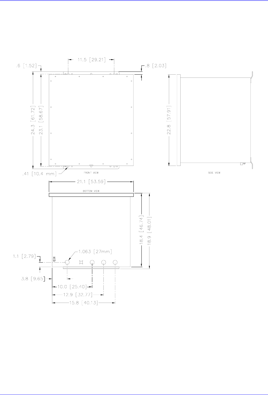
2 Equipment Dimensions and Mounting
SDE33075 Rev 1
Figure 2-1. SE Series Single Enclosure Dimensions
SOUTHERN AVIONICS COMPANY
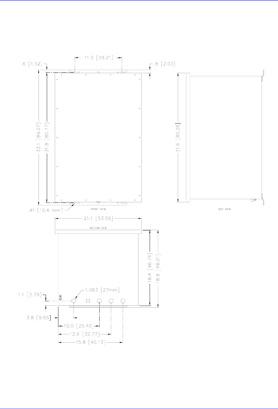
SE125 Installation and Setup2-2 Equipment Dimensions and Mounting
SDE33052 Rev 1
Figure 2-2. SE Series Dual Enclosure Dimensions
SOUTHERN AVIONICS COMPANY
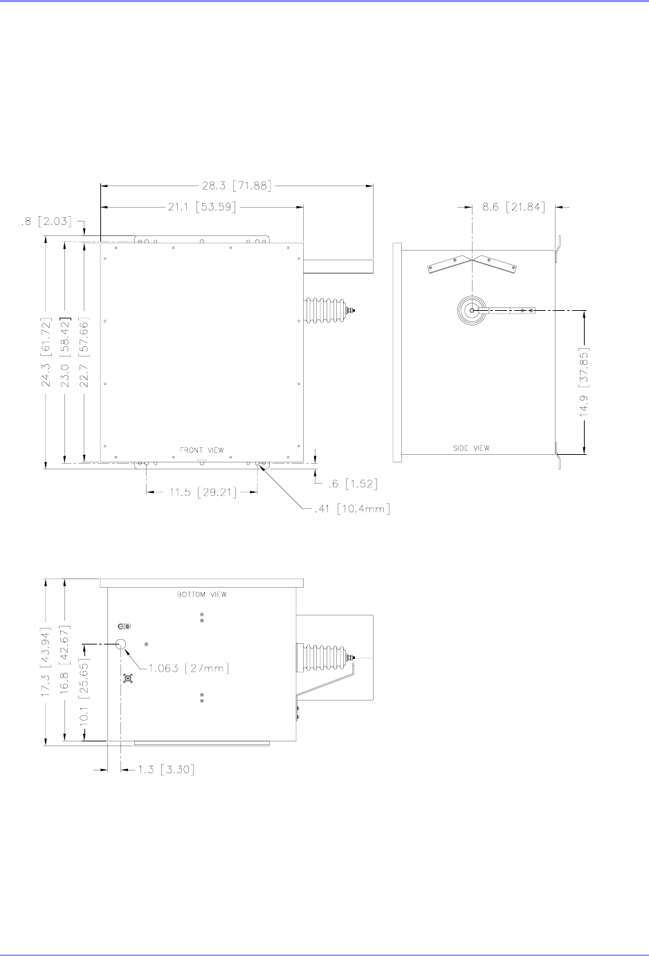
SE125 Installation and Setup 2-3Equipment Dimensions and Mounting
SDE69000 Rev C
Figure 2-3. PC1000C/3 IP66 Coupler Dimensions
SOUTHERN AVIONICS COMPANY
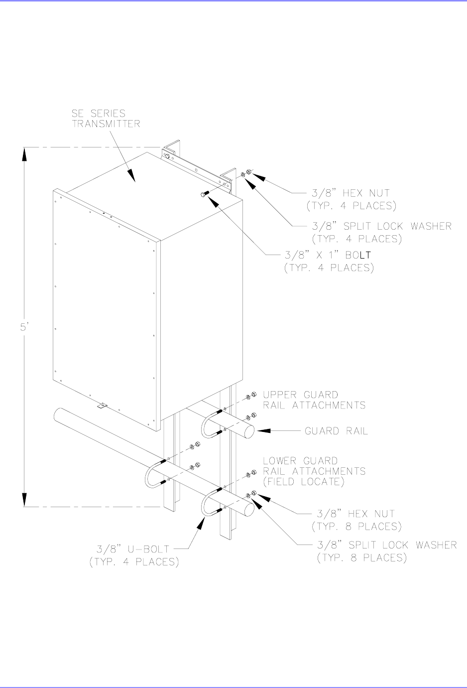
SE125 Installation and Setup2-4 Equipment Dimensions and Mounting
SDE33060 Rev 1
Figure 2-4. SE Transmitter mounted on offshore platform Guard Rails
SOUTHERN AVIONICS COMPANY
SE125 Installation and Setup 2-5Equipment Dimensions and Mounting
SDE07800 Rev B
Figure 2-5. PC1000C/IP66 Coupler Mounted on Guard Rails
SOUTHERN AVIONICS COMPANY
SE125 Installation and Setup2-6 Equipment Dimensions and Mounting
SDE33061 Rev A
Figure 2-6. SE Transmitter and Coupler Mounted on Steel “H” Beam
SOUTHERN AVIONICS COMPANY
SE125 Installation and Setup 2-7Equipment Dimensions and Mounting
SDE33062 Rev 1
Figure 2-7. SETransmitter and Coupler Mounted on Wooden Post
SOUTHERN AVIONICS COMPANY
SE125 Installation and Setup2-8 Equipment Dimensions and Mounting
SDE33063 Rev 1
Figure 2-8. SE Transmitter Mounted in Shelter

SOUTHERN AVIONICS COMPANY
SE125 Installation and Setup 3-1
3 Cable/Wire Selection, Routing and Connection
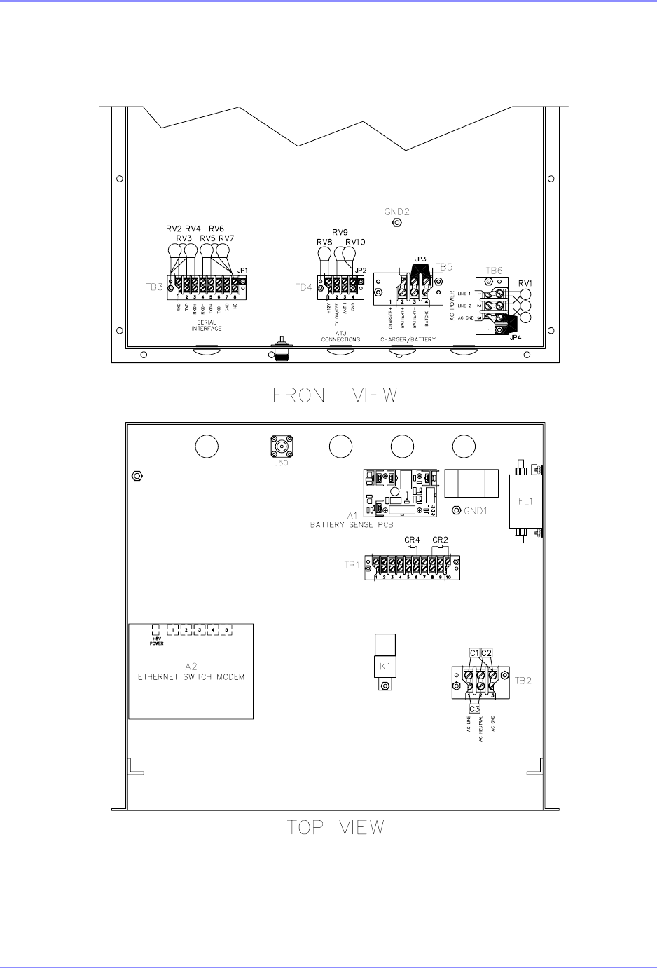
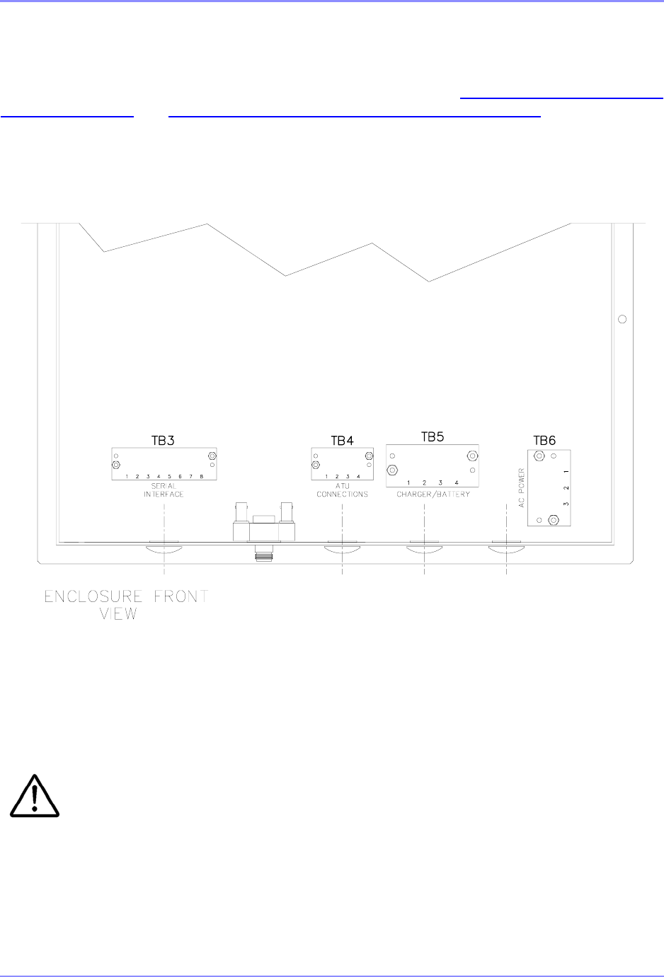
3.1 Gaining Access to the Power and I/O Terminal
Blocks
Requirements not supplied in Installation/ship kit.
1 - 11/32” nut driver (6”) to remove terminal block covers for TB5 and TB6
1 - #2 Phillips head screwdriver (6”) to loosen hardware on TB5 and TB6
1 - 1/4” nut driver (6”) to remove terminal block covers on TB4
1 - #1 Phillips head screwdriver (6”) to loosen hardware on TB4
The Ship kit is a part of the SE125 and contains the following:
1 - Alignment tool - 9A460000
2 - 7” Cable wraps - 9C013002
1 - 7’ Cable - SLW33010
2 - Conduit Assemblies - SLM25000, SLM25040
3.1.1
Prior to making any wiring connection, remove the four (4) dresser screws holding the lower
Transmitter Drawer in place. The drawer must be removed to allow full access to the system’s
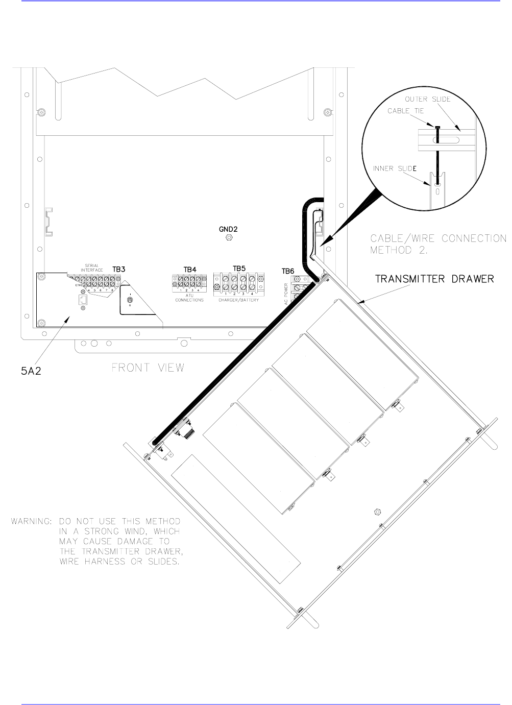
terminal blocks. Method 1 is desired and requires a work bench or stool of suitable height to
support the drawer. Method 2 simply suspends the drawer from the right extended outer slide
using a tie wrap. Refer to Figure 3-1. SE Series User Interface Diagram, Method 1 on Page 3- 2
and Figure 3-2. SE Series User Interface Diagram, Method 2 on Page 3- 3.
Warning: If Method 2 is used, ensure wind load on the suspended drawer will not cause
damage to the drawer slide, metal, terminal block, or wiring.
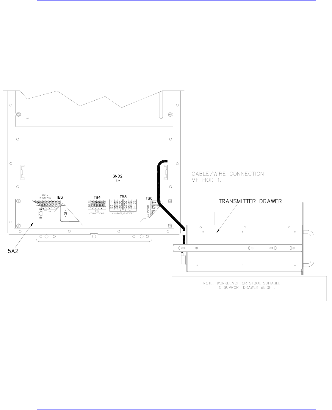
SOUTHERN AVIONICS COMPANY
SE125 Installation and Setup3-2
SDE33064 Rev B
Figure 3-1. SE Series User Interface Diagram, Method 1
SOUTHERN AVIONICS COMPANY
SE125 Installation and Setup 3-3
SDE33064 Rev B
Figure 3-2. SE Series User Interface Diagram, Method 2
SOUTHERN AVIONICS COMPANY
SE125 Installation and Setup3-4
3.2 System Grounding
3.2.1 Enclosure Mounted System
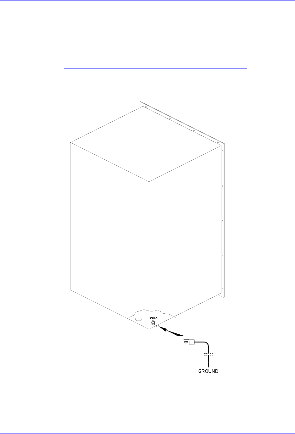
Connect the bronze ground lug, located on the outside bottom of the enclosure, to a good Earth
ground, as shown in Figure 3-3. System Ground - Enclosure Mount on Page 3- 4.
Recommended conductor: 12 AWG, multi-stranded copper wire, or better
SDE33065 Rev 1
Figure 3-3. System Ground - Enclosure Mount
SOUTHERN AVIONICS COMPANY
SE125 Installation and Setup 3-5
3.3 Transmitter Input Power
3.3.1 Maximum Input Current Requirements
The maximum continuous AC and DC current requirements are tabulated in Table 3-
1 and Table 3-2. The main AC and DC power breakers selected should be rated
accordingly and, in the case of the AC breaker, incorporate appropriate delay.
3.3.1.1 Single Transmitter
The maximum current is based on a single transmitter running at 125% maximum
power and 100% continuous modulation. Fault protection circuitry will shutdown the
system if these are exceeded.
Table 3-1 Single Transmitter MAX Input Current Requirements (Amps)
3.3.1.2 Dual Transmitter
The maximum current is based on both transmitters running simultaneously at 125%
maximum power and 100% continuous modulation. Fault protection circuitry will
shutdown the system if these are exceeded.
Table 3-2 Dual Transmitter MAX Input Current Requirements (Amps)
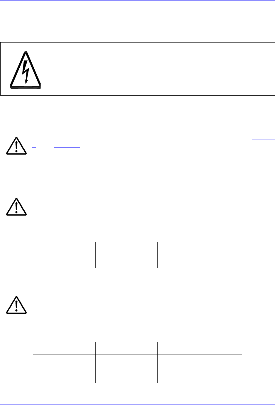
Danger: Shock Hazard. Serious injury or death from electrical
shock is possible when handling electrical power input wiring. Ensure AC
and DC main breakers are open. Observe any applicable standards
regarding Logout/Tagout (LOTO) procedures.
SYSTEM 100-264 VAC BATTERY (38-52VDC)
SE125 3.2 7.6
SYSTEM 100-264 VAC BATTERY (38-52VDC)
SE125 6.0 14.8
DC backup not intended for
test mode operation
SOUTHERN AVIONICS COMPANY
SE125 Installation and Setup3-6
3.3.2
Install the short piece of flexible conduit, contained in the ship kit (SLK33001), in one of the open
holes in the bottom of the transmitter’s enclosure, as shown in Figure 3-4. Conduits Access
Holes on Page 3- 6 and Figure 3-5. Conduit Connection Diagram on Page 3- 7.
SDE33066 Rev D
Figure 3-4. Conduits Access Holes
Since the manufacturer cannot anticipate the length of conduit needed for each
installation, a short length is provided for possible use. The user may provide a more
appropriate conduit, if desired.
SDE330066 Rev D
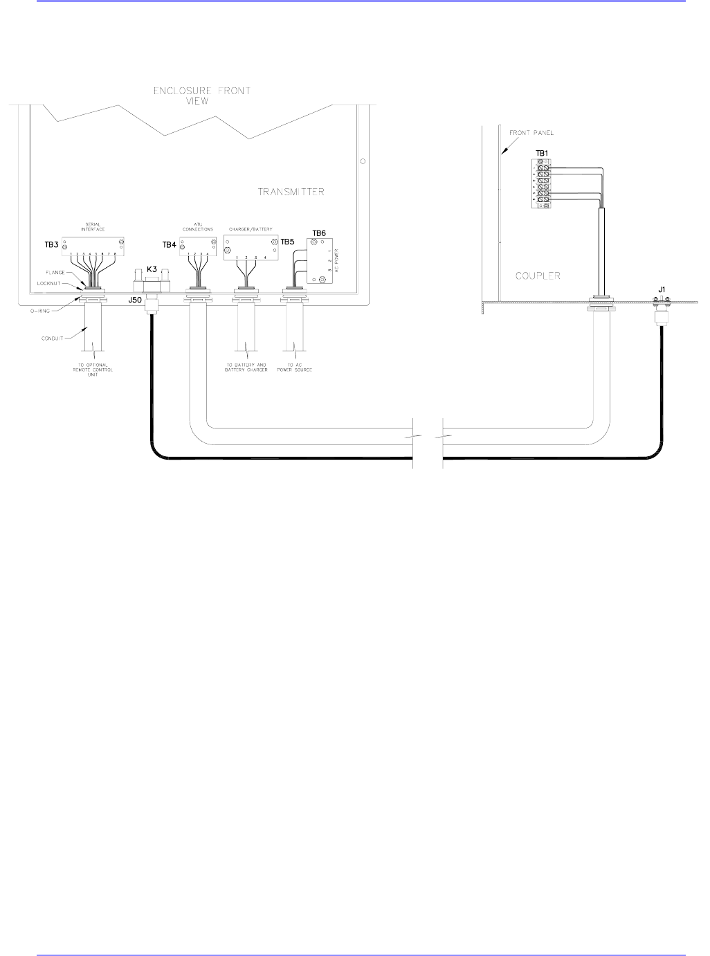
SOUTHERN AVIONICS COMPANY
SE125 Installation and Setup 3-7
SDE330066 Rev D
Figure 3-5. Conduit Connection Diagram
SDE33066 Rev C
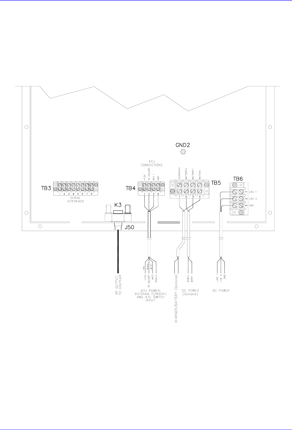
SOUTHERN AVIONICS COMPANY
SE125 Installation and Setup3-8
SDE33067 Rev D
Figure 3-6. SE Transmitter Wire Detail
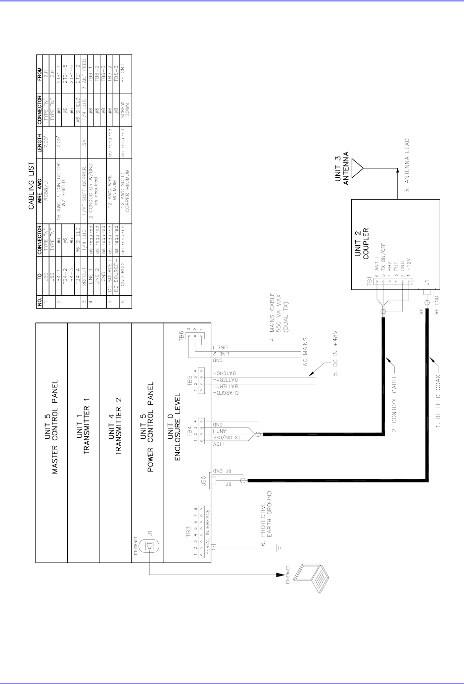
SOUTHERN AVIONICS COMPANY
SE125 Installation and Setup 3-9
SDE33055 Rev C
Figure 3-7. SE Series System Interconnect

SOUTHERN AVIONICS COMPANY
SE125 Installation and Setup3-10
The SE Series Transmitter is intended to operate from a secondary battery source
and primary AC source. The secondary DC source must be batteries or a source not
requiring suppression of conducted emissions.
If the system is provided with optional DC backup power, the DC power wiring
should be routed through a separate hole from the AC wiring.
Recommended conductors:
•AC Power - insulated 14AWG, multi-stranded, copper wiring; observe local electrical
code for insulator color
•DC Power (optional) - insulated 12AWG, multi-stranded, copper wiring; observe local
electric code for insulator color
3.3.2.1
For Steps 3.3.2.2 - 3.3.2.4, and Steps 3.3.2.6 - 3.3.2.7, if using battery backup, trim all wires to
the proper length for neat routing. Terminate the AC power wiring with insulated 14AWG, #8
crimp spade terminals (supplied in installation/ship kit). Terminate the optional DC power wiring
with the insulated 12AWG, #8 crimp spade terminals.
3.3.2.2
Connect AC Power line 1 (“hot” wire Line1 in 115 and 230VAC systems) to position 1 of TB6.
3.3.2.3
Connect AC Power line 2 (“neutral” wire in 115VAC or 230 single phase systems; “hot” wire
Line 2 in 220VAC two phase systems) to position 2 of TB6.
3.3.2.4
Connect AC Input ground to position 3 of TB6.
3.3.2.5
Connect the battery charger “-” (BATCHG-) lead to position 4 of TB5.
3.3.2.6
Connect DC Power BTRY+ (Battery “+”/positive wire of 48VDC battery stack) and the battery
charger “+” (BATCHG+) lead to position 2 and 1 of TB5 respectively.

SOUTHERN AVIONICS COMPANY
SE125 Installation and Setup 3-11
3.3.2.7
Connect DC Power BTRY- (Battery “-”/negative wire of 48VDC battery stack) to position 3 of TB5.
3.4 Coupler Power/Signal - Standard Band
3.4.1
Remove/open, the Coupler enclosure’s front panel.
3.4.2
Remove the Coupler's coil access panel located above the tuning controls panel, as shown in
Figure 9-1. Coupler Access Panel on Page 9-2
3.4.3
If the transmitter is mounted outdoors adjacent to the coupler as in Figure 2-6. SE Transmitter
and Coupler Mounted on Steel “H” Beam on Page 2- 6. install one end of the long flexible
conduit, contained in the installation kit, in the remaining open hole in the bottom of the
transmitter’s enclosure. Install the other end in the hole in the bottom of the coupler’s enclosure.
Refer to Figure 3-5. Conduit Connection Diagram on Page 3- 7 for typical installation.
If the transmitter is mounted in a shelter as in Figure 2-8. SE Transmitter Mounted in Shelter on
Page 2- 8, install the remaining short flexible conduit, contained in the installation kit in the
remaining open hole in the bottom of the transmitter’s enclosure. The user must provide a
conduit to route the wires/cables from the transmitter to the coupler.
3.4.4
Route the Coupler DC power cable and the Antenna Current/Coupler Switch cable, both supplied
with the installation kit, from inside the coupler’s enclosure, down through the conduit and up into
the bottom of the transmitter’s enclosure. Southern Avionics Company recommends a maximum
distance of 328ft (100m) for these two cables.
3.4.5 Transmitter Connections
3.4.5.1 Coupler Power, Current and Transmitter On/Off switch
•connect the red wire (+12VDC) to position 1 of TB4
•connect the black wire (TX On/Off) to position 2 of TB4
•connect the white wire (ANT I) to position 3 of TB4
•connect the cable’s shield to position 4 of TB4

SOUTHERN AVIONICS COMPANY
SE125 Installation and Setup3-12
3.4.6 Coupler Connections
Refer to Figure 9-2. PC1000C/3 Coupler cable connection on Page 9- 4 in the Coupler setup
section for wiring illustrations. If ATU is spaced further from the Transmitter than the distance
necessary to utilize the provided 7’ long interface cable, it will be necessary to provide the correct
length with proper terminations as described Figure 3-7. SE Series System Interconnect on Page
3- 9.
3.4.6.1 Coupler Power, Current and TX On/Off switch:
•connect the red wire (+12VDC) to position 1 of TB1
•connect the cable’s shield to position 2 of TB1
•connect the black wire (TX On/Off) to position 5 of TB1
•connect the white wire (ANT I) to position 6 of TB1
3.5 Optional Signal I/O
3.5.1
Remove the rubber knockout seal from one of the holes in the bottom of the transmitter
enclosure. Install a suitable conduit with a sealing connector.
3.5.2
Route all of the optional signal cables (MSK, Telephone, Voice) through the flexible conduit into
the bottom of the enclosure and over to the proper connector for Ethernet, MSK, Audio or modem
phone connection.
Recommended conductors:
•MSK RF Input - 20AWG, single conductor, shielded coaxial cable such as RG58, or
similar, terminated with a male BNC connector.
•Voice Input - 20AWG, two conductor, shielded cable terminated with a male RCA plug.

SOUTHERN AVIONICS COMPANY
SE125 Installation and Setup 3-13
3.5.3 MSK RF Input
If the user wishes to supply the system with an external RF signal instead of using the
internally generated one, the signal must be modulated in the Minimum Shift Keyed
(MSK) format. Typical inputs are 10dBm sine wave, 283.5 kHz to 325kHz with a 200
BPS data rate.
3.5.3.1
Connect the MSK signal cable to J1 of the Master Controller PCB 5A1A1.
3.5.4 Ethernet Interface
3.5.4.1
With the Ethernet cable routed to the interior of the enclosure, find the Ethernet switch and insert
in an available RJ45 port. See Figure 12-2. Ethernet Serial Server Installation Diagram on Page
12- 4.

SOUTHERN AVIONICS COMPANY
SE125 Installation and Setup3-14
This page intentionally left blank.
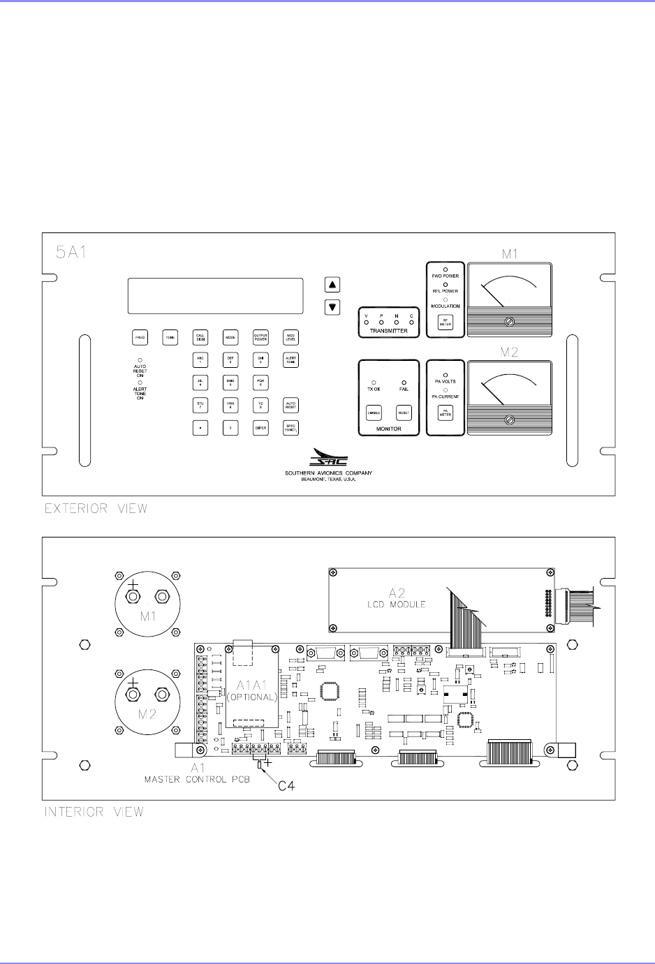
SOUTHERN AVIONICS COMPANY
SE125 Installation and Setup 4-1Master Control Panel Description
4 Master Control Panel Description
The Master Controller Panel is the main control panel for the SE series transmitters. The
following gives directions on how to operate the SE transmitter using the Master Controller Panel
keypad. The Master Controller keypad consists of 30 keys, 23 LEDs, a 4 line by 40 character
LCD display and dual analog meters.
SDE33011 Rev A
Figure 4-1. SE Master Control Panel

SOUTHERN AVIONICS COMPANY
SE125 Installation and Setup4-2 Master Control Panel Description
4.1 Meters
The upper analog meter monitors the following three functions
•Forward Transmit Power - Indicates how much radio frequency transmit power the SE
transmitter is sending to the ATU
•Reflected Transmit Power - Indicate how much, of the forward power, is being reflected
back to the transmitter from the ATU because of mismatches in the antenna impedance
•Modulation - Indicates the modulation index
The lower analog meter monitors the following two functions
•Power Amplifier Voltage (PAV) - This gives an indication of the voltage applied to the final
FETS in the Switching Power Amplifier
•Power Amplifier Current (PAI) - This gives an indication of the current flowing through the
final FETS in the Switching Power Amplifier
Taking these two values and multiplying them together will give an indication of the power input to
the final FETS.
SPA Power Input = PAV * PAI
The efficiency of the Switching Power Amplifier is calculated by taking the forward transmit power
from the upper meter and dividing this number by the calculated SPA power input to the final
FETS.
Efficiency (%) = (Forward Transmit Power)/(SPA Power Input) * 100%
4.2 Keys/LEDs
Frequency Key (FREQ) - This key sets the transmitting frequency of the transmitter. The
transmitter can be set to the desired frequency by pressing the FREQ key, then entering the
desired frequency using the numeric keys and then pressing the ENTER key. Although the
transmitter can cover any frequency from 190.0 KHz to 1800.0 KHz, the Filter/Monitor module
must be configured for the desired frequency.
Tone Key (TONE) - This key sets the tone frequency of the Identifier. The frequency can be
toggled to either 400 Hz or 1020 Hz using the tone key.

SOUTHERN AVIONICS COMPANY
SE125 Installation and Setup 4-3Master Control Panel Description
Call Sign Key (Call Sign) - This key allows the user to enter the identifier of the station. An
alphanumeric identifier up to 8 characters may be used. The default call sign is "SAC". Using
the numeric part of the keypad, the user may enter the identifier. This type of entry is identical to
text messaging on a cell phone. To begin this procedure, the operator presses the call sign key.
The present call sign, if present, will clear to all blanks. The most significant character is entered
first. For example, by pressing the "1" key the first time produces an “A” for the character.
Pressing the key again, changes the character from an “A” to a “B”. If the user continues to press
the "1" key, they would see the character "C" next, then the number "1", and then the character
"A" again. To keep the desired character, wait for 2 seconds and the character place will shift
over. This process continues until the entire identifier is in place. The user presses the enter key
and the identifier is stored into memory. An example of this procedure is as follows for an
Identifier “SAC”. The user would perform the following:
•press "CALL SIGN" key
•press the "7" key once
•wait 2 seconds
•press the "1" key once
•wait 2 seconds
•press the "1" key 3 times
•wait 2 seconds
•press "Enter" key.
This completes the operation.
Mode Key (MODE) - This key toggles between 3 modes of operation the SE transmitter will
operate in. They are as follows:
•Ident - In this mode the transmitter will send out the identifier of the transmitter. This
process repeats continuously.
•CARR - In this mode, the transmitter simply sends out a dead carrier with no modulation.
•CONT. - In this mode, the transmitter sends out a continuous tone.
Output Power -This key sets the RF output power of the transmitter. Press Output Power, enter
a power level between 0 and 125 Watts and then press Enter.
Modulation Level (Mod Level) - This key sets the amplitude modulation level of the transmitter.
Press Mod Level, enter a modulation level between 50% and 100%, and then press Enter.
Alert Tone - This key turns an audio alert tone ON or OFF. An LED (Alert Tone ON) on the left
hand side of the keypad indicates the status of Alert Tone.

SOUTHERN AVIONICS COMPANY
SE125 Installation and Setup4-4 Master Control Panel Description
DO NOT PRESS THIS KEY WITHOUT CONNECTING A DUMMY LOAD ON THE
OUTPUT OF THE TRANSMITTER NOT CURRENTLY OPERATING. DOING SO WILL
DAMAGE THE COAXIAL RELAY AND POSSIBLY ONE OR BOTH TRANSMITTERS.
Test Mode - This key allows both transmitters to operate at the same time. This mode is for
troubleshooting one transmitter while the other transmitter is still on the air. AN LED (TX1TX2
ON) on the left hand side of the keypad indicates whether both transmitters are activated.
Special Function (SPCL FCTN) - This switch is discussed under the special function section
4.3 on page 4-5.
LCD DATA - This switch allows the user to select the type of data that is seen on the LCD
Display whether it is operating parameters or special parameters including observed frequency,
modulation index, forward and reflected power. The LED's (TX1 TX2) below this switch indicate
which transmitter the data relates to.
UP/DWN Switches above LCD Data - These switches allow the user to scroll up and down
through the data observed or data selections.
Main TX Select (Main TX) - This switch allows the user to select which transmitter is selected as
the main transmitter - TX1 or TX2. The LED's (TX1 TX2) above the switch indicate which TX is
selected.
Monitor Enable (Enable) - This switch enables the transmitting monitoring circuitry. This
function monitors for a number of faults. These are: VSWR, Power, Continuous and No Tone.
RF Meter Select - This switch toggles through forward power, reflected power and modulation
index indicating which parameter is currently being viewed on the RF meter. An LED indicates
the selected parameter.
PA Meter - This switch toggles between PA voltage and PA current indicating which parameter is
displayed on the PA meter. An LED indicates the selected parameter.
4.2.1 Alarm Conditions:
VSWR Overload - This alarm occurs when the VSWR exceeds a preset limit.
Power Output OVER/UNDER - This alarm occurs when the output power either goes below or
above the preset limits set in the transmitter.
No Tone - This alarm occurs if the monitoring circuitry detects a No Tone Condition where the
transmitter is producing a dead carrier.
Continuous Tone - This alarm occurs when the monitoring circuitry detects a continuous tone
and not an identification sequence or low modulation (<70%).
These alarms are indicated by LED’s for each transmitter in the upper middle of the keypad.
These are indicated by

SOUTHERN AVIONICS COMPANY
SE125 Installation and Setup 4-5Master Control Panel Description
V = VSWR, P = Power, N = No Tone, and C = Continuous Tone
These alarms will cause a transmitter transfer in the case of a dual transmitter and a transmitter
shutdown in the case of a single.
Two other alarms that are indicated on the LCD, but not by LED, are
Observed Frequency - This alarm occurs when the built in frequency counter detects the
measured frequency is out of tolerance with the desired frequency.
Incorrect Identification - This alarm occurs when the monitoring circuitry detects a different
Identifier from the desired Identifier. The LED's above the monitor enable switch indicate the
present status of the transmitters. The PRI LED indicates the primary transmitter selected by the
main TX select key is the operating transmitter. The SEC LED indicates failure in the Primary
transmitter and the monitoring circuitry has commanded the transmitter to switch to the
secondary transmitter. The fail LED indicates that both transmitters have failed and the system
has shut down.
When testing the SE transmitter, Monitor Enable must be turned OFF.
4.3 Special Functions on the (SPCL FCTN) Key
All Functions are SPCL FCTN Key + Number
SPCL FCTN +1
This function stores all data into the onboard EEPROM. Once data is stored, the transmitter will
come back to the original settings if AC and DC power are lost.
SPCL FCTN +5
This function configures the Remote Control Unit.
SPCL FCTN +6
This function is a special test mode. In this mode the Master Controller will test for improper
identification. The Master Controller commands the Transmitter Control to add 32 to the ascii
value of every ID chararter. After the transmitter changes identification, it is still sending back
data on all of the parameters associated with that transmitter including identification. Once the
identification changes, the Master Controller will institute a transmitter changeover and shutdown
of the offending transmitter.
SPCL FCTN +7
This function is a special test mode. In this mode, the Master Controller will test for under power
shutdown. The Master Controller commands the Transmitter Controller to decrease the output
power by over 50%. As the transmitter changes power level, it is still sending back data on all of
the parameters associated with that transmitter. Once the power level drops below an
acceptable level, the Master Controller will institute a transmitter changeover and shutdown of
the offending transmitter.

SOUTHERN AVIONICS COMPANY
SE125 Installation and Setup4-6 Master Control Panel Description
SPCL FCTN +8
This function calibrates the modulation power, antenna current and frequency for each
transmitter. This offset compensates for the error that exists between the Transmitter Control
digital to analog converter and the measured output.
SPCL FCTN +9
This function configures the DCAD or network for SE systems.
SPCL FCTN +0 (Software not available at this time)
This function puts the Master Controller into a logging mode. It stores all pertinent data for a
given interval.
SPCL FCTN + “Down Arrow Key” (Software not available at this time)
This test function tests the linearity of the forward/reflected power and modulation meter. First
the Master Controller commands the Transmitter Control to increase the RF output power in
increments of 5 Watts starting at 10 Watts and increasing to 125 Watts. It then reverses and
decreases by 5 Watts until the transmitter returns to 10 Watts output. It then will start increasing
the modulation level by 5% from 0 to 95%. The modulation then returns to 0% and the unit goes
back to power increase and decrease.

SOUTHERN AVIONICS COMPANY
SE125 Installation and Setup 5-1Network Control Program Software (optional)
5 Network Control Program Software (optional)
Network Requirements:
•Desktop or laptop personal computer (PC) running Vista, XP or Windows 7
•Operating System: Microsoft Windows
•Mouse or touchpad
•Windows Internet Explorer or FireFox (preferred)
•Network IP capability
•Ethernet cable
5.1 Network IP Configuration
If the user does not have an IP address, set the IP address, network Mask, and gateway as
described in Section 6.6 on page 6-15. In some instances you may need to contact your network
administrator for assistance.
5.2 WEB Watch Program Software
The main Web Watch window is shown below, and the following four groups are used for
transmitter system monitoring.
•Transmitter status (Power ON/OFF, Primary TX selected (dual only), ATU ON/OFF, TEST
mode ON/OFF and voice present)
•System status (PRI, SEC, FAIL) and TX shutdowns / Faults
•Overall system parameters (i.e. Date/Time, Call Sign, Frequency, Fwd, RFL Power, etc.)
•Transmitter parameters include Built In Test Equipment readings for

SOUTHERN AVIONICS COMPANY
SE125 Installation and Setup5-2 Network Control Program Software (optional)
1. Low Voltage Regulator and High Voltage Power Supply (LV/HVPS)
2. Power Control and Modulator Input/Output (PCM)
3. Switching Power Amplifier (SPA)
The Web Watch program includes ten operational controls buttons:
•Power (ON/OFF)
•Toggle (from TX1 or TX2 to allow LCD view / control) - Dual only
•Monitor (Enable or Disable fault shutdown)
•Primary TX (TX1 or TX2) - Dual only
•TX Setup (RF Frequency, Tone Frequency, Call Sign, TX Mode, RF Power Level, and
Modulation Level)
•Calibration (Power Factor, Modulation Display Error, Tone Factor (1020Hz), Power
Display Error, Frequency, and Antenna Factor)
•IP Configuration (IP Address, Network Mask, and Gateway)
•Time & Date
•Site Location
•Save
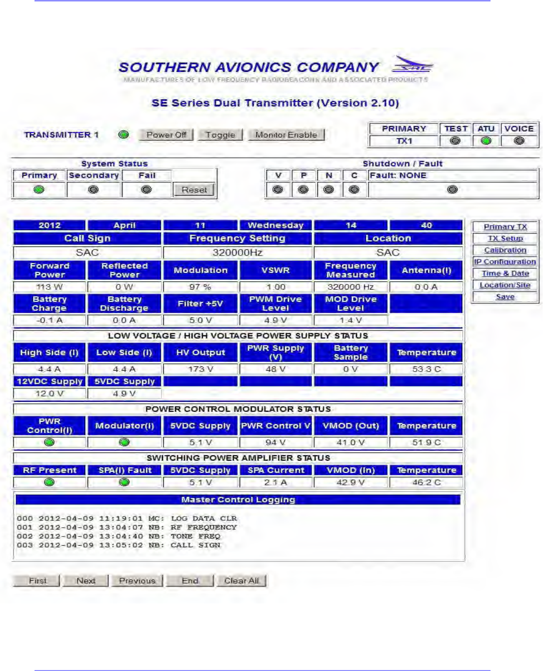
SOUTHERN AVIONICS COMPANY
SE125 Installation and Setup 5-3Network Control Program Software (optional)
Figure 5-1. Web GUI Main Window (Dual system)

SOUTHERN AVIONICS COMPANY
SE125 Installation and Setup5-4 Network Control Program Software (optional)
This page intentionally left blank.
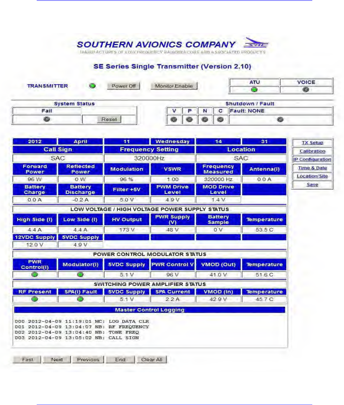
SOUTHERN AVIONICS COMPANY
SE125 Installation and Setup 5-5Network Control Program Software (optional)
Figure 5-2. Web GUI Main Window (Single system)

SOUTHERN AVIONICS COMPANY
SE125 Installation and Setup5-6 Network Control Program Software (optional)
This page intentionally left blank.

SOUTHERN AVIONICS COMPANY
SE125 Installation and Setup 6-1System Site Configuration
6 System Site Configuration
6.1 Control Program Initialization
Once the SE125 has been installed, the system is ready for operation. The unit is powered on by
the AC power switch located on the Power Control Panel. Actuating this switch begins the
initialization process. The SE125 will proceed through two initialization screens on the LCD
indicating which version of firmware is being used. When communicating with the factory, please
have the version available. The system will default to transmitter 1 as the primary transmitter;
LCD data on TX1, Monitor Enabled, FWD POWER meter, PA VOLTS meter, and System Status
are also primary. All other functions are turned OFF. The initialization screens are as follows:
SE125
Southern Avionics Company
Beaumont Texas USA
Firmware Version X.XX © 2010
SE125
Initialization System
Please wait …
MM-DD-YYYY
SE125
8-bit;1-stop;ODD-parity;19200
NO XON/XOFF
RCU ID: 0

SOUTHERN AVIONICS COMPANY
SE125 Installation and Setup6-2 System Site Configuration
Or
NOTE: Normally the ATU switch should be in the ON position. If the ATU switch is OFF, the SE
system will show the ATU message (shown below) automatically on the main menu.
The dual or single transmitter system will be defined in the upper left hand side of the screen
following “SE SERIES” (see Main Menu above). If any faults exist, they will be shown in the
upper right hand side of the screen. Additional display screens are chosen by using the UP and
DOWN keys to more menus which show the overall / transmitter data.
The dual system also utilizes the following four keys:
•LCD DATA - to choose TX1 or TX2 display and control.
•TEST MODE - to allow both transmitters to operate simutaniously for testing purposes.
•MAIN TX - to allow primary/secondary assignment monitor.
•MONITOR (system status: PRI, SEC, FAIL) - to enable or disable monitoring usually for
testing purposes.
Use the UP key to cancel or go the previous menu anytime.
SE SERIES [DUAL] Fault: NONE
RF Frequency Setting ......... 320000 Hz
Tone Frequency Setting ....... 1020 Hz
Call Sign: SAC TX Mode:IDENT
SE SERIES [SINGLE] Fault: NONE
RF Frequency Setting ......... 320000 Hz
Tone Frequency Setting ....... 1020 Hz
Call Sign: SAC TX Mode:IDENT
********* ATU SWITCH IS OFF **********
Please check hardware.
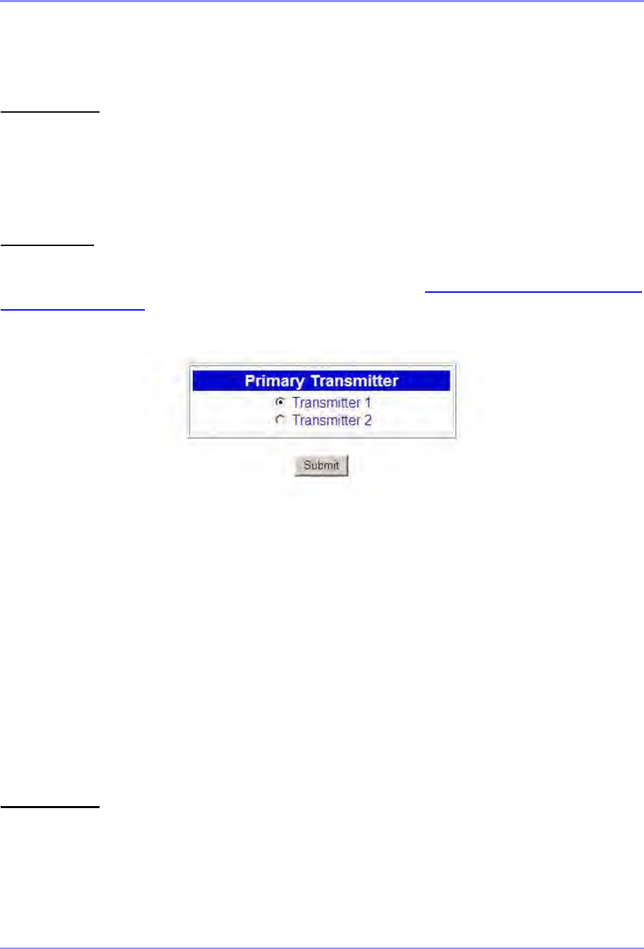
SOUTHERN AVIONICS COMPANY
SE125 Installation and Setup 6-3System Site Configuration
6.2 Primary Transmitter Selection (Dual)
LCD DISPLAY
Use the MAIN TX key to change TX1 <->TX2 as primary transmitter.
Example: Press the MAIN TX key to change to TX2. The TX2 green indicator will illuminate and
the TX1 indicator will extinguish.
WEB WATCH
In the SE SERIES TRANSMITTER Web Watch window, click on Primary TX from the right column box on
the Main window to open the Primary Transmitter window, shown in Figure 6-1. Primary Transmitter
Window on Page 6-3.”
Figure 6-1. Primary Transmitter Window
CAUTION:
This window allows the user to select which transmitter is primary in a dual transmitter system. In
the case of a single transmitter system, the Transmitter 2 option is not allowed, and the Primary
TX key will not be functional.
6.3 Transmitter Display Selection (Dual)
LCD DISPLAY
Use the LCD DATA key to select TX1 or TX2 for display / control of the transmitter.

SOUTHERN AVIONICS COMPANY
SE125 Installation and Setup6-4 System Site Configuration
WEB WATCH
Click on the Toggle button on the Main menu to toggle between TX1 and TX2 for display and
control of the Transmitter.
6.4 Transmitter Setup
This section details how to set RF frequency, tone frequency, call sign, power and modulation as
dictated by the site license.
6.4.1 RF Frequency Setup
LCD DISPLAY
Press the FREQ key to open the RF FREQUENCY ENTRY menu as shown below.
Repeat pressing the FREQ key to clear then enter the desired frequency in the field.
When the ENTER key is pressed, the RF power level will be set to 0 Watts immediately to protect
the transmitter.
Press SPCL FCTN then 1 to store any changes.
WEB WATCH
In the SE SERIES TRANSMITTER Web Watch window, click on Setup in the right column box
on the Main window to open the Transmitter 1/2 : Setup window shown in Figure 6-2. Web
GUI Transmitter Setup Window on Page 6-5.
RF FREQUENCY ENTRY
FREQ should be between 190K and 1800K Hz
Enter RF Frequency: [ 320000] Hz
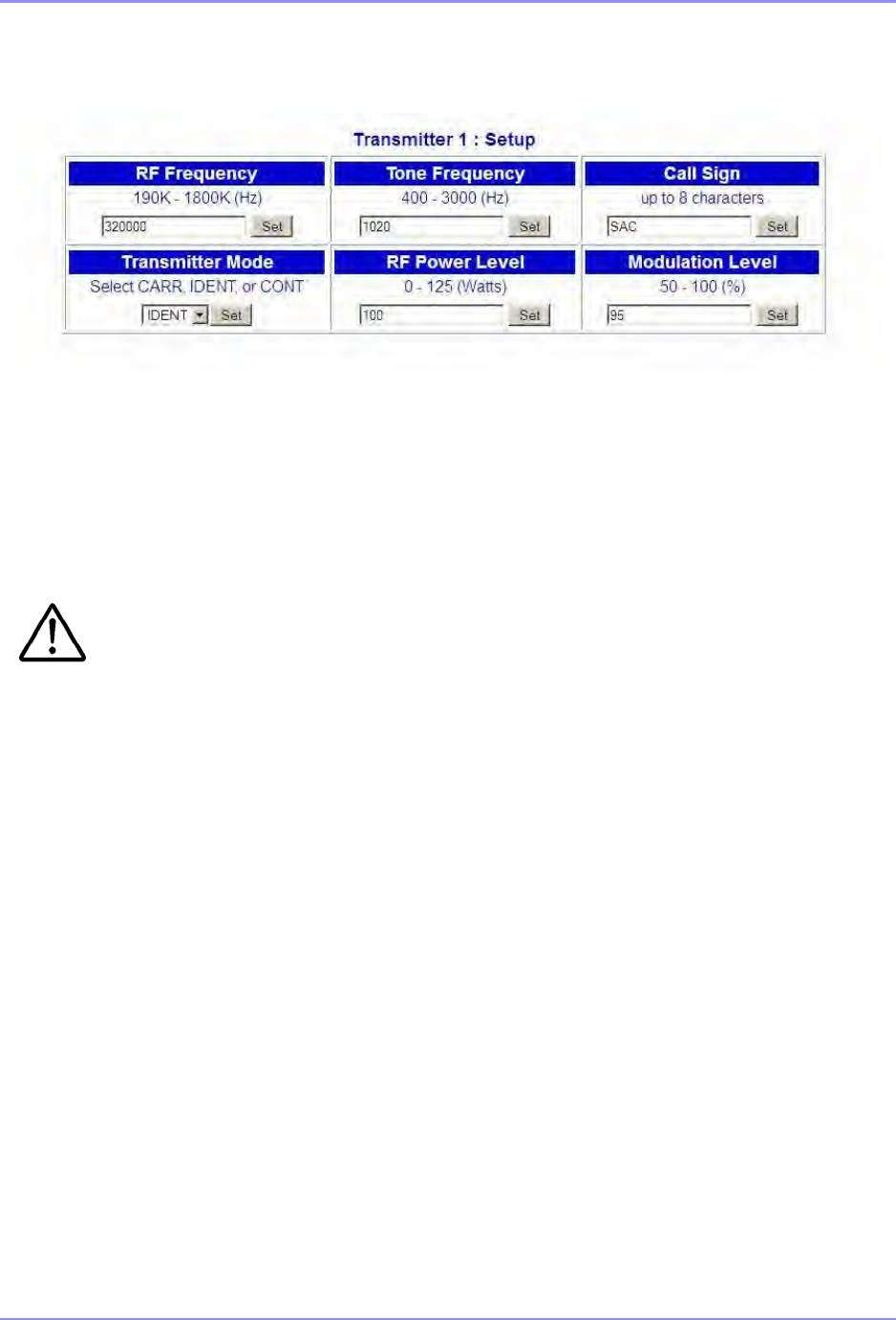
SOUTHERN AVIONICS COMPANY
SE125 Installation and Setup 6-5System Site Configuration
Figure 6-2. Web GUI Transmitter Setup Window
After making changes, click the Set button to send the value toTransmitter Control board
memory.
Click the Back button to close the Transmitter Setup window and return to the Main window.
Verify beforehand that any frequency selected is within the Filter/Bridge modules
configuration limits as described below:
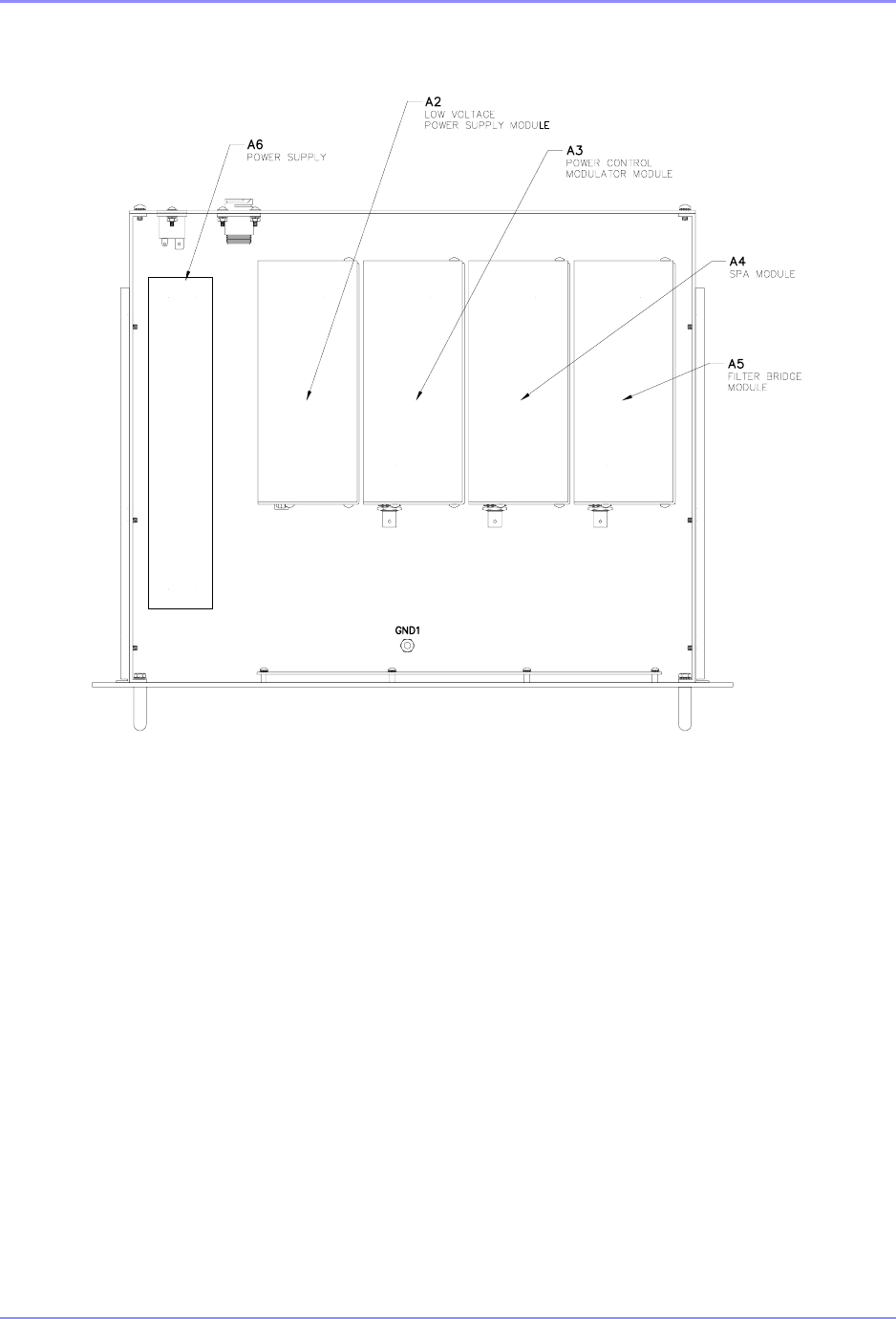
SOUTHERN AVIONICS COMPANY
SE125 Installation and Setup6-6 System Site Configuration
SDE33200 Rev 1
Figure 6-3. SE Transmitter Drawer Diagram
The Filter/Bridge PCB includes a modified 10 element Butterworth-Cauer low pass filter capable
of more than 60dB harmonic attenuation, a broadband RF power bridge, a modulation envelope
detector and associated level sampling circuitry. The entire PCB is enclosed in a metal
enclosure to form a module. The module is available in three different bands, Standard (190-
650kHz), Medium (500-1250kHz) and High (1500-1800kHz).
The Standard and Medium band filters are further subdivided as follows:
Standard Band: 190-300kHz, 300-450kHz and 450-650kHz
Medium Band: 500-750kHz, 700-950kHz and 900-1250kHz
These sub-bands are selected using on board jumpers, JP1 – JP10 as indicated in the tables
below.

SOUTHERN AVIONICS COMPANY
SE125 Installation and Setup 6-7System Site Configuration
6.4.2 Tone Frequency Setup
LCD DISPLAY
Press the TONE key to toggle between 400 Hz or 1020 Hz.
WEB WATCH
In the Transmitter 1 : Setup window, for instance, Transmitter 1 is selected as shown in Figure
6-2. Web GUI Transmitter Setup Window on Page 6-5. Enter the desired tone frequency and
click the Set button to send the desired value to the Transmitter Control board.
When the transmitter setup is done completely, click the Back button to close the Transmitter
Setup window and return to the Main window.
STANDARD BAND 190‐300kHz 300‐450kHz 450‐650kHz
JP1 A,B,C,D,E A,C,D D
JP2 OPEN B A
JP3 A,B,C,D A,B B
JP4 A,B,C,D A,B,D D
JP5 OPEN B A
JP6 D A,C B
JP7 C,D A,B,C C
JP8 OPEN B A
JP9 A,B,C,D B,D C,D
JP10 C,D,E B,D A,E
MEDIUM BAND 500‐750kHz 700‐950kHz 900‐1250kHz
JP1 E A,D B,C
JP2 OPEN B A
JP3 B,D A,D A,C
JP4 A,B,C,D,E A,B,C,D B,C
JP5 OPEN B A
JP6 C,D A,D B,C
JP7 A,B,D D A,C
JP8 OPEN B A
JP9 A,D A,C A,B,D
JP10 A,C,D A,D B,C

SOUTHERN AVIONICS COMPANY
SE125 Installation and Setup6-8 System Site Configuration
6.4.3 Call Sign Setup
LCD DISPLAY
Press the CALL SIGN key to open the CALL SIGN ENTRY menu, as shown below.
Repeat pressing the CALL SIGN key to clear the entry in the field box.
Press the ENTER key when complete.
WEB WATCH
In the Transmitter 1 : Setup window shown in Figure 6-2. Web GUI Transmitter Setup Window
on Page 6-5.” Set the Call Sign as desired, then click the Set button to send the value to
Transmitter Control board memory.
When transmitter setup is complete, click the Back button to close the Transmitter Setup
window and return to the Main window.
6.4.4 Transmitter Mode Setup
There are three options CARR, CONT, IDENT.
LCD DISPLAY
Press the MODE key to toggle the CARR, CONT, IDENT.
Example: change from IDENT to CARR by pressing the MODE key on the LCD screen as shown
below
CAL SIGN ENTRY
Enter 1 to 8 Characters
Entry Call Sign: SAC
SOUTHERN AVIONICS COMPANY
SE125 Installation and Setup 6-9System Site Configuration
WEB WATCH
Select the desired mode from the pulldown menu and click on Set to send the mode to
Transmitter Control board memory.
6.4.5 RF Power Level Setup
CAUTION: Ensure that the RF Frequency setting corresponds to that of the Filter
PCB.
LCD DISPLAY
Press the OUTPUT POWER key to open the RF POWER SETTING menu, as shown below
Repeat pressing the OUTPUT POWER key to clear the RF power level in the field box. Enter the
desired power using the keypad.
When the ENTER key is pressed, the Master Control will send the desired level to the
Transmitter Control board memory.
WEB WATCH
Operates similarly to the LCD DISPLAY above.
SE SERIES [DUAL] Fault: NONE
RF Frequency Setting ......... 320000 Hz
Tone Frequency Setting ....... 400 Hz
Call Sign: SAC TX Mode: CARR
---------- RF POWER SETTING ----------
POWER should be 0 through and 125.
Enter RF Power Level: [100] Watts

SOUTHERN AVIONICS COMPANY
SE125 Installation and Setup6-10 System Site Configuration
6.4.6 Modulation Level Setup
LCD DISPLAY
Press the MOD LEVEL key to open the MODULATION SETTING menu, as shown below
Repeat pressing the MOD LEVEL key to clear the modulation level in the field box.
Enter the mod level desired using the keypad.
WEB WATCH
Operates similar to the LCD DISPLAY above.
6.5 Transmitter Calibration
This section details how to calibrate the RF Frequency output, the RF output power, the
Modulator output and the RF power displayed.
Using the SPCL FCTN key to open the special function menu as shown below
Select the 8 key to open the calibration menu as shown below
---------- MODULATION SETTING ---------
MOD Level should be between 50% and 100%.
Enter Modulation Level: [ 95]%
1=STORE 7=PWR TEST
2=LOGGING 8=CALIBRATE
5=RCU 9=SYSTEM
6=ID TEST

SOUTHERN AVIONICS COMPANY
SE125 Installation and Setup 6-11System Site Configuration
6.5.1 RF (Power Factor) Calibration (Output adjustment)
Transmitters are factory calibrated at 125W for an operating range of 10-125 Watts. If desired
operating range is 10-25 Watts, the Transmitter must be calibrated at 25 Watts. Power
calibration should only be done locally with the system connected to a 50 Ohm dummy load, or
incorrect readings could result.
LCD DISPLAY
Press the 1 key to open the POWER FACTOR CALIBRATION menu, as shown below.
Enter the Power Factor value in the field box to make the value measured, by either a power
meter or oscilloscope, agree with the output power selected. If the measurement is being made
using an oscilloscope, the power factor value should be adjusted until the waveform’s peak-to-
peak voltage reaches the correct value.
Observe that the value displayed in the Forward Power comes into agreement with the true
power measured by the power meter or the oscilloscope.
Press the ENTER key to store then exit.
Select the following key ---------------
1.Power Factor Cal 4.Power Display Error
2.MOD Factor Cal 5.Tone Calibration
3.Frequency Cal 6.Anteena Current Cal
------ POWER FACTOR CALIBRATION -------
Power Factor should be between 5 and 250.
Enter power factor: [100]
LOADDUMMY
2
PP R
22
V
P¸
¸
¹
·
¨
¨
©
§
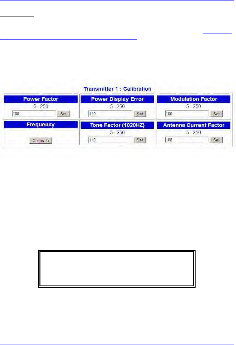
SOUTHERN AVIONICS COMPANY
SE125 Installation and Setup6-12 System Site Configuration
WEB WATCH (Locally connected)
In the SE SERIES TRANSMITTER Web Watch window, click on Calibration in the right column
box on the Main window to open the Transmitter 1 : Calibration window shown in Figure 6-4.
Web GUI Transmitter Calibration Window on Page 6-12.
Operation is similar to the LCD DISPLAY above. Click set to save the change.
Figure 6-4. Web GUI Transmitter Calibration Window
6.5.2 Modulation Factor Calibration (display adjustment)
LCD DISPLAY
Press the 2 key to open the MODULATION CALIBRATION menu, as shown below.
Set the modulation level to 100%. Verify that this is actually 100% modulation by monitoring the
RF waveform envelope on the dummy load. Vary the MOD Factor and press enter. Do this until
the scope displayed modulation is 95%.
--- MODULATION FACTOR CALIBRATION ---
MOD Factor should be between 5 and 250.
Enter modulation factor: [100]

SOUTHERN AVIONICS COMPANY
SE125 Installation and Setup 6-13System Site Configuration
WEB WATCH (Locally connected)
Operates similar to the LCD DISPLAY above. See Figure 6-4. Web GUI Transmitter Calibration
Window on Page 6-12.
6.5.3 Frequency Calibration (display adjustment)
LCD DISPLAY
Press the 3 key to open the FREQUENCY CALIBRATION menu, as shown below.
Enter the measurement from the test frequency counter and press the ENTER key. After a few
moments, the measured frequency displayed on the LCD screen should agree with the test
equipment measurement. After a few seconds, the screen returns to the home menu
automatically.
WEB WATCH (Locally connected)
Operates similar as LCD DISPLAY above. See Figure 6-4. Web GUI Transmitter Calibration
Window on Page 6-12.
6.5.4 Power Display Error Calibration (display adjustment)
Note: Scope connected to 50 Ohm dummy load to read true ouput power.
LCD DISPLAY
Press the 4 key to open the POWER DISPLAY ERROR CALIBRATION menu, as shown below.
-------- FREQUENCY CALIBRATION -------
Setting: 320000HZ Measured:320000HZ
ENTER = Calibrate

SOUTHERN AVIONICS COMPANY
SE125 Installation and Setup6-14 System Site Configuration
Change the factor number and press return to achieve the proper LCD RF power readout
agreeing with the scope.
WEB WATCH
Operates similar to the LCD Display above.
6.5.5 Tone Calibration
Set Tone to 1020Hz. Enter the tone factor to agree with 95% modulation seen on the scope, then
store by using SPCL FCTN +”1”.
WEB WATCH
Operates similar to the LCD Display above.
6.5.6 Antenna Calibration
LCD DISPLAY
Operates similar to the Web Watch below.
WEB WATCH
•Under Calibration, verify the antenna factor is set to 100 (default).
•The displayed value of antenna current should be made to agree with the value on the
ATU meter by adjusting the factor until identical readings are achieved.
When the transmitter calibration is complete, click the Back button to close the Transmitter
Calibration window and return to the Main window.
---- POWER DISPLAY ERROR CALIBRATION ---
P.D.E Factor should be between 5 and 250.
Enter display error factor: [100]

SOUTHERN AVIONICS COMPANY
SE125 Installation and Setup 6-15System Site Configuration
6.6 DCAD (DC Automatic Disconnect)
LCD DISPLAY
Press the SPCL FCTN key, then the 9 key to open the SE SYSTEM menu, as shown below.
Press the 1 key to toggle “ON” or “OFF” on the LCD screen, then the ENTER key to exit. ENTER
must be pressed to store the selection or it will be lost.
WEB WATCH
(Not available)
6.7 Network IP Configuration
LCD DISPLAY
Press the SPCL FCTN key, then the 9 key to open the SE SYSTEM menu, as shown below.
Press the 2 key to open the Network IP on the LCD screen, then select one of the following
numbers:
-------------- SE SYSTEM -------------
1. DCAD . . . . . . . . . . . . . . [OFF]
2. Network
Press ENTER key to confirm, then exit.
-------------- SE SYSTEM -------------
1. DCAD . . . . . . . . . . . . . . [OFF]
2. Network
Press ENTER key to confirm, then exit.
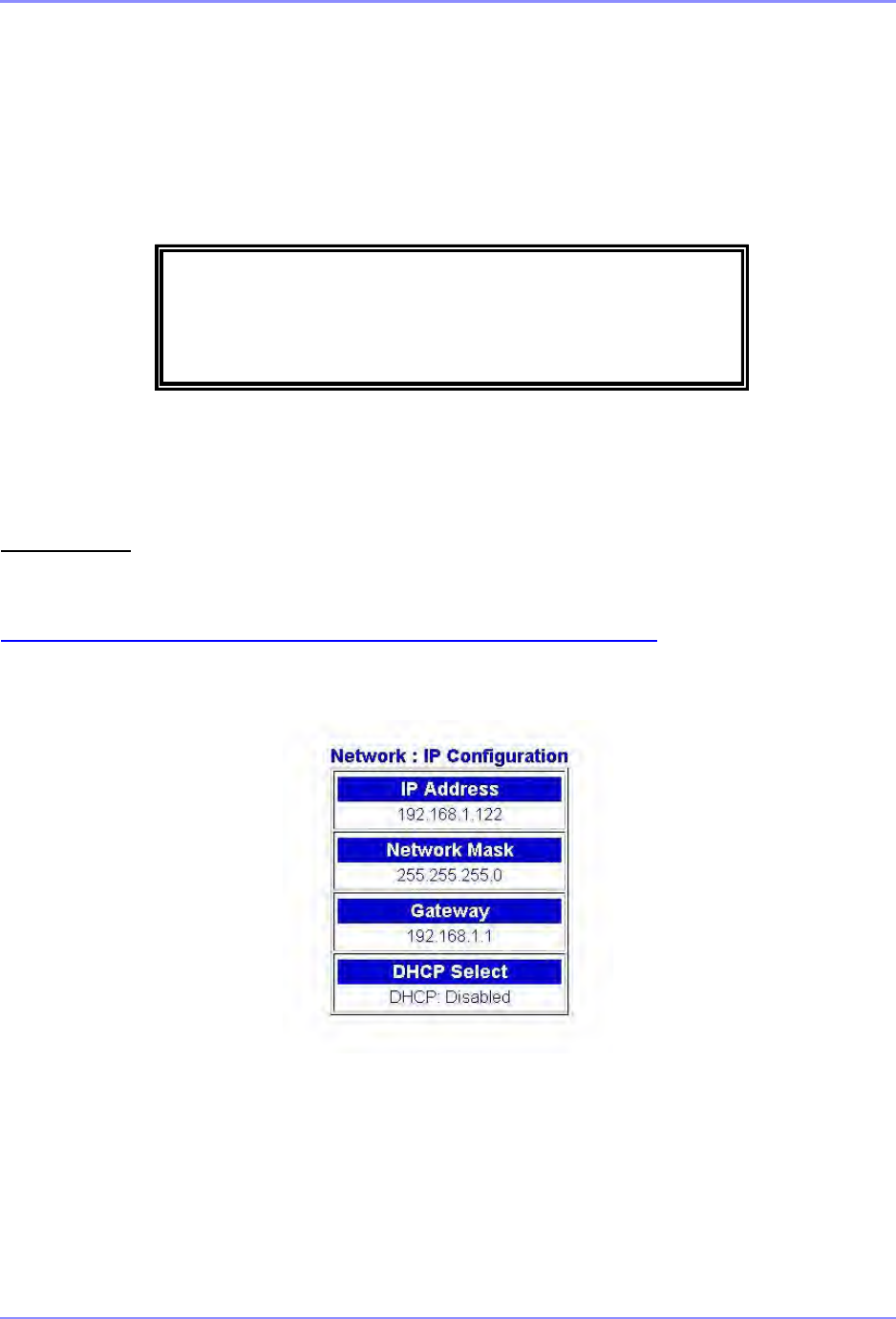
SOUTHERN AVIONICS COMPANY
SE125 Installation and Setup6-16 System Site Configuration
1. DHCP
2. IP Address
3. Netmask
4. Gateway
Press the Enter key to confirm the Network IP settings.
WEB WATCH (Read Only)
In the SE SERIES TRANSMITTER Web Watch window, click on the IP Configuration from the
right column box on the Main menu to open the Network : IP Configuration window, shown in
Figure 6-5. Web GUI Network IP Configuration Window on Page 6-16.
Figure 6-5. Web GUI Network IP Configuration Window
1. DHCP: [ENABLED]
2. IP Address: 192.168.1.122
3. Netmask: 255.255.255.0 Press ENTER
4. Gateway: 192.168.1.1 to confirm
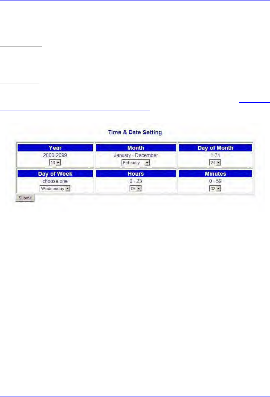
SOUTHERN AVIONICS COMPANY
SE125 Installation and Setup 6-17System Site Configuration
6.8 Time & Date Setting
LCD DISPLAY
NONE
WEB WATCH
In the SE SERIES TRANSMITTER Web Watch window, click on the Time & Date from the right
column box on the Main menu to open the Time & Date Setting window, shown in Figure 6-6.
Web GUI Time & Date Setting Window on Page 6-17.
Figure 6-6. Web GUI Time & Date Setting Window
After setting parameters desired, click the Submit button to store them in Netburner EEPROM
memory.
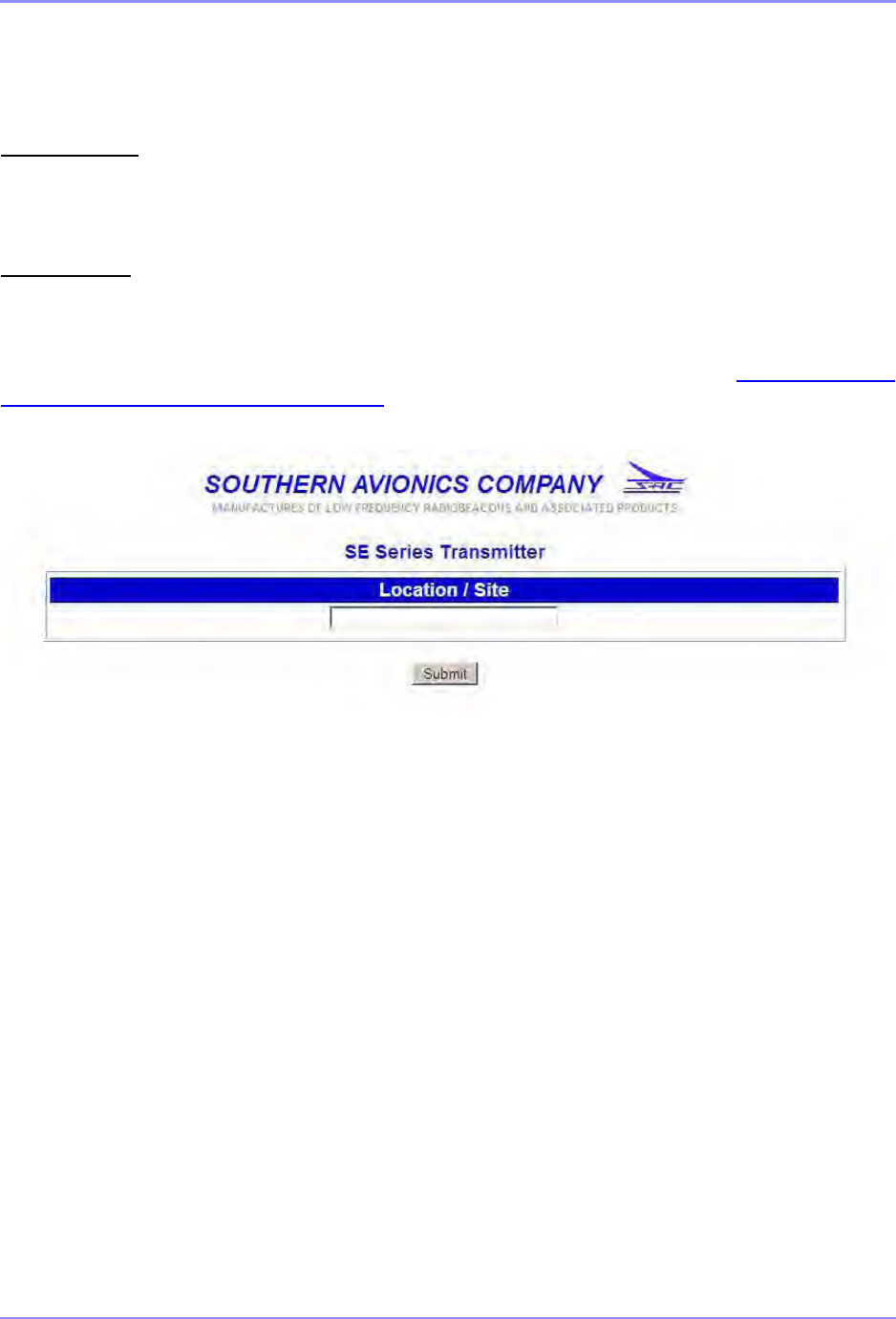
SOUTHERN AVIONICS COMPANY
SE125 Installation and Setup6-18 System Site Configuration
6.9 Location Site Setting
LCD DISPLAY
NONE
WEB WATCH
In the SE SERIES TRANSMITTER Web Watch window, click on the Location Site in the right
column box on the Main window to open the Location Site window, shown in Figure 6-7. Web
GUI Location Site Window on Page 6-18.
Figure 6-7. Web GUI Location Site Window
A maximum of 30 characters are allowed for the location site name. Click the Submit button to
store in (EEPROM) memory on the NETBURN board.

SOUTHERN AVIONICS COMPANY
SE125 Installation and Setup 6-19System Site Configuration
6.10 Monitor Enable
LCD DISPLAY
Press the ENABLE key to open the MONITOR menu, as shown below (transmitter 1 is selected).
Press ENABLE to toggle “ENABLED” or “DISABLED” on the LCD screen, then the ENTER key
to exit. ENTER must be pressed to store the selection.
WEB WATCH
Operates similar to the LCD DISPLAY above.
6.11 Transmitter Data
Using the DOWN or UP arrow key to view the following previous or next menu as below:
------------ TRANSMITTER 1 -----------
MONITOR . . . . . . . . . . . . [ENABLED]
Press ENTER key to confirm, then exit.
------------ TRANSMITTER 1 -----------
FORWARD PWR : 100W VSWR : 1.00
RFFLECTED PWR: 0W ANTENNA(I): 2.4A
MODULATION: 95% FREQ : 320000HZ
------------ TRANSMITTER 1 -----------
PWM DRV LVL: 4.9V MOD DRV LVL: 1.3V
FILTER +5V : 5.0V
BTRY CHARGE: 2.7A BTRY DISCH : 2.1A

SOUTHERN AVIONICS COMPANY
SE125 Installation and Setup6-20 System Site Configuration
------- LV/HVPS STATUS (1 of 2) ------
PWR SUPPLY(V): 48V BTRY SAMPLE: 48V
HIGH SIDE(I) : 4.0A LOW SIDE(I): 4.1A
HV OUTPUT : 207V TEMPERATURE: 32.1C
------- LV/HVPS STATUS (2 of 2) ------
12VDC SUPPLY: 12.0V 5VDC SUPPLY: 5.0V
---- POWER CONTROL MODULATOR STATUS ----
PWR CTRL (I): PASS MODULATOR(I): PASS
POWER CTRL V: 96V VMOD (OUT) : 41.2V
TEMPERATURE : 34.1C 5VDC SUPPLY : 5.0V
--- SWITCHING POWER AMPLIFIER STATUS ---
RF PRESENT : PASS SPA(I) FAULT: PASS
SPA CURRENT: 2.2A VMOD (IN) : 42.1V
TEMPERATURE: 31.2C 5VDC SUPPLY : 5.0V

SOUTHERN AVIONICS COMPANY
SE125 Installation and Setup 6-21System Site Configuration
6.12 Active Monitoring and Control
Transmitter shutdown (single) or transfer (dual) conditions:
• loss of modulation (carrier only, duration = 30 sec)
• low modulation (70%, duration = 30 sec)
• continuous modulation (no keying, duration = 30 sec)
• low power (50%, duration = 30 sec)
• high power (125%, duration = 30 sec)
• VSWR (> 2.62:1, duration = 2 sec)
• under-temperature (< - 40C, duration = 120 sec)
• over-temperature (> 70C, duration = 120 sec)
• under-frequency (> 100Hz, duration = 120 sec)
• over-frequency (> 100Hz, duration = 120 sec)
• ID sequence error (immediate action)

SOUTHERN AVIONICS COMPANY
SE125 Installation and Setup6-22 System Site Configuration
SE125 Series Transmitter
User Software Default Setup
Version 2.01
SITE CONFIGURATION
Location <Blank>
Call Sign “SAC”
Tone Frequency 1020 Hz
RF Frequency 320K Hz
DOT 125m sec
DOT SPACE 125m sec
DASH 375m sec
DASH SPACE 375m sec
WAIT SPACE 2 sec
SHUTDOWN
Monitor Enable
VSWR 2.62
VSWR Timeout 5 sec
Power – Low -3dB
Power – High +2dB
Power – Timeout 30 sec
Modulation – Low 70%
Continuous Tone 30 sec
Modulation – Timeout 30 sec
OTHER SHUTDOWN
Power Supply (48V) < 45V
DCAD – Low Voltage < 38V
DCAD Enable YES
Temperature -40ºC to 70ºC
Temperature Timeout 120 sec
Frequency PPM 100 Hz
Frequency Timeout 120 sec
CALIBRATION
Power Factor 100
Dummy Load 50 OHM
Modulation Factor 100
Co-Efficient (0) 0.0300490
Co-Efficient (1) 0.0138441
Antenna Factor 10
TRANSMITTER
Primary Transmitter Transmitter 1
Transmitter Mode IDENT
Auto RF Power Up at Startup YES

SOUTHERN AVIONICS COMPANY
SE125 Installation and Setup 6-23System Site Configuration
LOCAL / REMOTE CONTROL PANEL
RF Meter FWD POWER
PA Meter PA VOLTS
LCD Data TX1
LED - AUTO RESET ON OFF
LED – ALERT TONE ON OFF
LED – TX1 TX2 ON (Test Mode) OFF
LED - MONITOR PRI
LED – MAIN TX TX1
SITE CONFIGURATION

SOUTHERN AVIONICS COMPANY
SE125 Installation and Setup6-24 System Site Configuration
This page intentionally left blank.

SOUTHERN AVIONICS COMPANY
SE125 Installation and Setup 6-25System Site Configuration
6.13 Logging Firmware
Logging Requirements:
•FRAM device, U27, on the Master Control board SLP43300
•Use of the Real Time Clock device on the Master Control board
•Latest firmware installed in both the Master Control and Embedded Ethernet Server.
In either a dual or a single SE Transmitter system, the SE Master Control panel firmware records
Date & Time stamp, Transmitter fault/shutdown and any Operator changes using U27’s 32K
bytes of FRAM on the Master Control board. The standard format follows:
nnn YYYY-MM-DD hh:mm:ss dddddddddddddddd
nnn = logged line number (3 characters)
YYYY = year (4 chars)
MM = month (2 chars)
DD = day of month (2 chars)
hh = hour (2 chars)
mm = minutes (2 chars)
ss = seconds (2 chars)
d… = data type. Either TX fault/shutdown or User changes (16 chars)
6.13.1 Local Logging
The user has the option to view, on the Master Control panel, logged data containing Faults,
Shutdowns and User Changes recorded for TX1 and TX2 for dual systems. When the LCD DATA
key is set for TX1’s data display, logged data represents only TX1’s activity. Alternately, when the
LCD DATA key is set for TX2’s data display, logged data represents TX2’s activity. A total of 300
lines of logged data for TX1 and another 300 lines logged for TX2 is available for the customer to
scroll through at any given time. Once the 300 line limit is reached the oldest entry will fall out of
the history. There are 40 bytes (characters) maximum on each line (row) on the LCD display as
seen below. Two functions allow the user to manage the logged data at the LCD “View” and
“Clear”. Below are examples of the front panel LCD. The Master Control panel captures any
user changes from the Web Watch screen or the Remote Control Unit.

SOUTHERN AVIONICS COMPANY
SE125 Installation and Setup6-26 System Site Configuration
The user presses the SPCL FCTN key to open the standard window below with Logging added as
option 2.
By pressing the 2 key for Logging the logging menu below is seen.
6.13.1.1 Logging – Clear
Press the 1 key to clear all TX logged data as shown below. The Please Wait processing message will
appear on the LCD display.
You can verify the cleared logged data message is viewed correctly using pressing the SPCL FCTN +
2 + 2 keys to view logged data window as shown below.
1=STORE 7=PWR TEST
2=LOGGING 8=CALIBRATE
5=RCU 9=SYSTEM
6=ID TEST
-------------- Logging -------------
1. Clear 2. View
Please ENTER to exit
000 2012-03-21 08:12:57 MC: LOG DATA CLR

SOUTHERN AVIONICS COMPANY
SE125 Installation and Setup 6-27System Site Configuration
6.13.1.2 Logging – View
Press the SPCL FCTN + 2 + 2 keys to see the SE system’s newest logged data on the LCD
display.
By using the ▲ or ▼ key the user can view all logged events.
Logging No Date Time TX Fault or Operating Change
↓ ↓ ↓ ↓
By pressing the ▲ key, older data is viewed. By pressing the ▼ key, newer data is viewed.
If the user wishes to exit to the Home menu, press the ENTER key.
6.13.2 Remote Logging (Web Watch)
Web Watch continuously requests all logged information stored in FRAM on the Master Control
Panel. The following five buttons on the Web Watch window are used to view and clear data. The
remote Web Watch screen shows the same information as the Local LCD display described
above.
000 2012-03-05 14:12:03 MC: LOG DATA CLR
001 2012-03-19 10:01:57 MC: SYSTEM RESET
002 2012-03-20 06:12:44 AC FAILURE
003 2012-03-20 06:15:21 PWR UP COMPLETE
Oldest →
004 2012-03-20 06:16:57 MC: OUTPUT POWER
005 2012-03-20 06:17:04 MC: MONITOR
006 2012-03-20 06:22:05 FAULT: NO TONE
007 2012-03-20 06:23:19 MC: SYSTEM RESET
Newest →

SOUTHERN AVIONICS COMPANY
SE125 Installation and Setup6-28 System Site Configuration
1. First – selected to view the oldest logged data.
2. Next – selected to view the next group of four data lines.
3. Previous – selected to view the previous group of four data lines.
4. End – selected to view the newest logged data.
5. Clear All – clear all logging data on TX (TX1 or TX2)
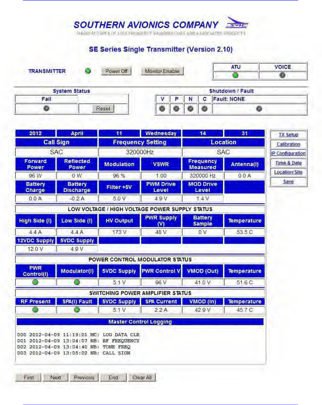
SOUTHERN AVIONICS COMPANY
SE125 Installation and Setup 6-29System Site Configuration
SOUTHERN AVIONICS COMPANY
SE125 Installation and Setup6-30 System Site Configuration

SOUTHERN AVIONICS COMPANY
SE125 Installation and Setup 6-31System Site Configuration
6.14 List of Logging Label Names
A maximum of 16 display characters (representing) TX faults, shutdowns, and user changes are
displayed after a Date and Time stamp.
For example:
000 2012-03-23 14:20:55 (16 characters of data)
The following TX faults can occur on either Transmitter 1 or Transmitter 2 and will be
independently logged:
•VSWR
Display: “FAULT: VSWR”
•Low Power
Display: “FAULT: LOW POWER”
•High Power
Display: “FAULT: HIGH PWR”
•No Tone
Display: “FAULT: NO TONE”
•Low Modulation
Display: “FAULT: LOW MOD”
•Continuous Tone
Display: “FAULT: CONT TONE”
•ID Code
Display: “FAULT: ID CODE”
•Over/Under Frequency
Display: “FAULT: FREQUENCY”
•MOD Temperature
Display: “FAULT: MOD TEMP”
•SPA Temperature
Display: “FAULT: SPA TEMP”
•HVPS Temperature
Display: “FAULT: HVPS TEMP”
•Power Control(I) Overload 1
Display: “FAULT: PWR CTLi1”

SOUTHERN AVIONICS COMPANY
SE125 Installation and Setup6-32 System Site Configuration
•Power Control(I) Overload 2 (500 Watt TX)
Display: “FAULT: PWR CTLi2”
•Power Control(I) Overload 3 (1000 Watt TX only)
Display: “FAULT: PWR CTLi3”
•Power Control(I) Overload 4 (1000 Watt TX only)
Display: “FAULT: PWR CTLi4”
•Modulator(I) Overload 1
Display: “FAULT: MOD(I) 1”
•Modulator(I) Overload 2 (500 Watt TX)
Display: “FAULT: MOD(I) 2”
•Modulator(I) Overload 3 (1000 Watt TX only)
Display: “FAULT: MOD(I) 3”
•Modulator(I) Overload 4 (1000 Watt TX only)
Display: “FAULT: MOD(I) 4”
•SPA(I) Overload 1
Display: “FAULT: SPA(I) 1”
•SPA(I) Overload 2 (500 Watt TX)
Display: “FAULT: SPA(I) 2”
•SPA(I) Overload 3 (1000 Watt TX only)
Display: “FAULT: SPA(I) 3”
•SPA(I) Overload 4 (1000 Watt TX only)
Display: “FAULT: SPA(I) 4”
•RF Present
Display: “FAULT: RF DDS”
•I2C Timeout
Display: “I2C TIMEOUT” (not available)
•AC Failure
Display: “AC FAILURE”
•TX Mismatch (checksum)
Display: “TX MISMATCH” (not available)
•DCAD – Low Voltage
Display: “DCAD LOW VOLTAGE”
•Software Error
Display: “SOFTWARE ERROR” (not available)

SOUTHERN AVIONICS COMPANY
SE125 Installation and Setup 6-33System Site Configuration
The following are User Induced Operating Changes which will be logged when acted on.
LCD display:
Master Control (MC = Front Panel Changes)
•“MC: RF FREQUENCY”
•“MC: TONE FREQ”
•“MC: CALL SIGN”
•“MC: TX MODE”
•“MC: OUTPUT POWER”
•“MC: MOD LEVEL”
•“MC: AUTO RESET” (not available)
•“MC: TEST MODE ON”
•“MC: MAIN TX”
•“MC: SYSTEM RESET”
•“MC: MONITOR”
•“MC: POWER CAL”
•“MC: PWR DSP CAL”
•“MC: TONE CAL”
•“MC: FREQ CAL”
•“MC: MOD CAL”
•“MC: ANTENNA CAL”
•“MC: STORE EEPROM”
•“MC: DCAD SET”
•“MC: NETWORK SET”
•“MC: RCU SET”
•“MC: LOG DATA CLR”
•“MC: PASSWORD” (not available)
Netburner (NB = Web Interface Changes)
•“NB: RF FREQUENCY”

SOUTHERN AVIONICS COMPANY
SE125 Installation and Setup6-34 System Site Configuration
•“NB: TONE FREQ”
•“NB: CALL SIGN”
•“NB: TX MODE”
•“NB: OUTPUT POWER”
•“NB: MOD LEVEL”
•“NB: MAIN TX”
•“NB: SYSTEM RESET”
•“NB: MONITOR”
•“NB: POWER CAL”
•“NB: PWR DSP CAL”
•“NB: TONE CAL”
•“NB: FREQ CAL”
•“NB: MOD CAL”
•“NB: ANTENNA CAL”
•“NB: STORE EEPROM”
•“NB: RTC SET”
•“NB: LOG DATA CLR”
•“NB: PASSWORD” (not available)
•“NB: TX POWER OFF”
•“NB: TX POWER ON”
Remote Control Unit (RC = RCU Changes)
•“RC: TX POWER OFF”
•“RC: TX POWER ON”
•“RC: MAIN TX”
•“RC: SYSTEM RESET”
Default SE Transmitter System level sequences or changes
•“PWR UP COMPLETE”
•“DISABLE ALL” (not available)
•“ATU SWITCH OFF”

SOUTHERN AVIONICS COMPANY
SE125 Installation and Setup 7-1Operational Checks
7 Operational Checks
At the heart of the SE series system is a class D Power Amplifier that operates through a low pass
filter, with RF sourced from a Direct Digital Synthesizer (DDS). The embedded microprocessor
lends itself nicely to automatic adjustment of system operating parameters. However, to ensure
proper operation, verification with calibrated test equipment is required.
7.1 Test Equipment Required
3 1/2 digit digital multi-meter (DMM), calibrated
dual trace oscilloscope, calibrated
frequency counter, calibrated (± 1 Hz accuracy)
250 Watt, 50 Ohm non-reactive dummy load
7.2 Dummy Load Hookup
Connect a 250 Watt, 50 Ohm, non-reactive dummy load to the RF output jack (J50), an N Type
RF connector, on the bottom of the enclosure.
7.3 Power Up
Switch the AC switch (S2) to the ON position.
7.4 Power Up Verification
Observe the following sequence of Front Panel LCD displays:
SE125
Southern Avionics Company
Beaumont Texas USA
Firmware Version X.XX © 2010
SE125
Initialization System
Please wait …
MM-DD-YYYY

SOUTHERN AVIONICS COMPANY
SE125 Installation and Setup7-2 Operational Checks
7.5 Transmitter #1 RF Power Level Checks
7.5.1
Connect an oscilloscope or a calibrated power meter to the system's RF output at the dummy load.
7.5.2
Use the MAIN TX key to select TX1 as primary transmitter. Green LED’s will illuminate indicating
which TX is Primary. Select TX1 as Primary.
7.5.3
Use the LCD DATA key to select TX1 as the display / control transmitter data.
7.5.4
In the Monitor section press the ENABLE key until “Disabled” is displayed on the LCD. Press
ENTER to store this condition. This action will be necessary until shutdown testing is performed
later in this section.
7.5.5
Press the FREQ key to open the RF FREQUENCY ENTRY menu, as shown below.
SE SERIES [DUAL] Fault: NONE
RF Frequency Setting ......... 320000 Hz
Tone Frequency Setting ....... 1020 Hz
Call Sign: SAC TX Mode:IDENT
RF FREQUENCY ENTRY
FREQ should be between 190K and 1800K Hz
Enter RF Frequency: [ 320000] Hz

SOUTHERN AVIONICS COMPANY
SE125 Installation and Setup 7-3Operational Checks
7.5.6
Enter the desired frequency of operation using the numeric keypads then press ENTER to store
the selection. (If necessary press the FREQ key repeatedly to clear the RF frequency field).
7.5.7
Press the TONE key to toggle between 400 Hz and 1020 Hz modulation frequency.
7.5.8
Enter the desired call-sign using the numeric keypads then press ENTER to store the selection.
Press the CALL SIGN key to open the CALL SIGN ENTRY menu, as shown below. (If
necessary press the CALL SIGN key repeatedly to clear the call sign field).
7.5.9
Press the MODE key to toggle the CARR, IDENT, CONT., to Carrier Mode (CARR).
7.5.10
Press the OUTPUT POWER key to open the RF POWER SETTING menu, as shown below.
7.5.11
Key in the desired power level for the site and press ENTER to store and activate that level. In a
few seconds, the power output level selected should register on the meter and voltage on the PA
meter should be indicated.
CALL SIGN ENTRY
Enter 1 to 8 Characters
Entry Call Sign : SAC
---------- RF POWER SETTING ----------
POWER should be 0 through 125
Enter RF Power Level: [100] Watts

SOUTHERN AVIONICS COMPANY
SE125 Installation and Setup7-4 Operational Checks
Record the readings for PA voltage and PA current for reference data to be used in Section
10 for proper Antenna tuning and matching.
7.5.12
Verify the output RF power level measured at the dummy load agrees (within 5%) with the value
displayed on the LCD in the Transmitter 1 section.
7.6 Transmitter #1 Modulation Level Check
7.6.1
Press the MOD LEVEL key to open the MODULATION SETTING menu, as shown below.
Press the MOD LEVEL key repeatedly to clear the modulation level box.
Enter 95% modulation and press ENTER to store that level.
7.6.2
Scope the modulation waveform and record the max/min envelope values to calculate the
modulation percentage. (vmax-vmin)/(vmax+vmin)=mod%
7.6.3
Verify the set modulation percentage (displayed on the LCD) and the calculated modulation
percentage agree to within 5%.
---------- MODULATION SETTING ---------
MOD Level should be between 50% and 100%.
Enter Modulation Level: [ 95]%

SOUTHERN AVIONICS COMPANY
SE125 Installation and Setup 7-5Operational Checks
7.7 Transmitter #1 Frequency Checks
7.7.1
As an example, when calibrating RF output frequency, International Civil Aviation Organization
(ICAO) regulations state a maximum variance of + 100 parts per million (ppm) Hertz is allowed
provided the ouput frequency is less than 1606.5 kHz.
The formula for calculating the variance at 100ppm is::
variance = (operating frequency * 100) / 1,000,000
For example, at 320,000 kHz the variance allowed would be 32 Hz.
7.7.2
Connect a calibrated frequency counter to the dummy load to measure the RF output frequency.
7.7.3
Verify the measured frequency equals the site frequency ± 100 ppm Hz. If the frequency is within
this tolerance, disconnect the frequency counter. If it is out of tolerance, verify frequency
counter’s accuracy, and contact Southern Avionics’ technical department for further assistance.
7.8 Transmitter #1 Morse Code Identifier Check
7.8.1
Attach the oscilloscope to the dummy load and verify the output RF modulation envelope is being
keyed with the site’s required Morse code identifier entered earlier in this section. Refer to
Figure 7-1. Morse code Identifier detail, on page 7-6 to assist in verification.
SOUTHERN AVIONICS COMPANY
SE125 Installation and Setup7-6 Operational Checks
SDE10060 Rev A
Figure 7-1. Morse code Identifier detail

SOUTHERN AVIONICS COMPANY
SE125 Installation and Setup 7-7Operational Checks
7.8.2
This completes general operational tests of transmitter #1.
7.9 Transmitter #2 RF Power Level Checks (Dual
systems)
7.9.1
Connect an oscilloscope or a calibrated power meter to the system's RF output at the dummy load.
7.9.2
Use the MAIN TX key to select TX2 as primary transmitter. Green LED’s will illuminate indicating
which TX is Primary. Select TX2 as Primary.
7.9.3
Use the LCD DATA key to select TX2 as the display / control transmitter data.
7.9.4
In the Monitor section press the ENABLE key until “Disabled” is displayed on the LCD. Press
ENTER to store this condition. This will be necessary until shutdown testing is performed later in
this section.
7.9.5
Press the FREQ key to open the RF FREQUENCY ENTRY menu, as shown below.
7.9.6
Enter the desired frequency of operation using the numeric keypads then press ENTER to store
the selection. (If necessary press the FREQ key repeatedly to clear the RF frequency field).
RF FREQUENCY ENTRY
FREQ should be between 190K and 1800K Hz
Enter RF Frequency: [ 320000] Hz

SOUTHERN AVIONICS COMPANY
SE125 Installation and Setup7-8 Operational Checks
7.9.7
Press the TONE key to toggle between 400 HZ and 1020 HZ modulation frequency.
7.9.8
Enter the desired call-sign using the numeric keypads then press ENTER to store the selection.
Press the CALL SIGN key to open the CALL SIGN ENTRY menu, as shown below.
7.9.9
Press the MODE key to toggle the CARR, IDENT, CONT. to Carrier Mode (CARR).
7.9.10
Press the OUTPUT POWER key to open the RF POWER SETTING menu, as shown below.
7.9.11
Key in the desired power level for the site and press ENTER to store and activate that level. In a
few seconds, the power output level selected should register on the meter and voltage on the PA
meter should be indicated.
7.9.12
Verify the output RF power level measured at the dummy load agrees (within 5%) with the value
displayed on the LCD in the Transmitter 2 section.
CAL SIGN ENTRY
Enter 1 to 8 Characters
Entry Call Sign: SAC
---------- RF POWER SETTING ----------
POWER should be 0 through and 125.
Enter RF Power Level: [100] Watts

SOUTHERN AVIONICS COMPANY
SE125 Installation and Setup 7-9Operational Checks
7.10 Transmitter #2 Modulation Level Check
7.10.1
Press the MOD LEVEL key to open the MODULATION SETTING menu, as shown below.
Press the MOD LEVEL key repeatedly to clear the modulation level box.
Enter 95% modulation and press ENTER to store that level.
7.10.2
Scope the modulation waveform and record the max/min envelope values to calculate the
modulation percentage. (vmax-vmin)/(vmax+vmin)=mod%
7.10.3
Verify the set modulation percentage (displayed on the LCD) and the calculated modulation
percentage agree to within 5%.
7.11 Transmitter #2 Frequency Checks
7.11.1
As an example, when calibrating RF output frequency, International Civil Aviation Organization
(ICAO) regulations state a maximum variance of + 100 parts per million (ppm) Hertz is allowed
provided the ouput frequency is less than 1606.5 kHz.
---------- MODULATION SETTING ---------
MOD Level should be between 50% and 100%.
Enter Modulation Level: [ 95]%

SOUTHERN AVIONICS COMPANY
SE125 Installation and Setup7-10 Operational Checks
The formula for calculating the variance at 100ppm is:
variance = (operating frequency * 100) / 1,000,000
For example, at 320,000 kHz the variance allowed would be 32 Hz.
7.11.2
Connect a calibrated frequency counter to the dummy load to measure the RF output frequency.
7.11.3
Verify the measured frequency equals the site frequency ± 100 ppm Hz. If the frequency is within
this tolerance, disconnect the frequency counter. If it is out of tolerance, verify frequency
counter’s accuracy, and contact Southern Avionics’ technical department for further assistance.
7.12 Transmitter #2 Morse Code Identifier Check
7.12.1
Attach the oscilloscope to the dummy load and verify the output RF modulation envelope is being
keyed with the site’s required Morse code identifier entered earlier in this section. Refer to
Figure 7-1. Morse code Identifier detail on page 6 to assist in verification.
This completes general operational tests of Transmitter #2.
7.13 Shutdown Tests Setup
7.13.1
Note: fault indications will appear on the LCD for the transmitter selected to display. After a
shutdown transfer occurs, the LCD DATA key must be pressed to display fault information for the
TX that caused the transfer.
7.13.2
Set up both TX1 and TX2 with the same parameters. Set both transmitters in the normal IDENT
mode by pressing to MODE key.

SOUTHERN AVIONICS COMPANY
SE125 Installation and Setup 7-11Operational Checks
7.13.3
Using the LCD DATA key to select either TX1 or TX2, turn both transmitter monitors on by
pressing ENABLE in the monitor section until the LCD reads enable and press ENTER to store this
condition.
7.14 No Tone Shutdown Test - Loss of Modulation
7.14.1
Set TX1 as the PRIMARY transmitter by pressing the MAIN TX key.
7.14.2
Set TX1 mode to CARR (carrier only) by pressing the MODE key. The transmitter should
shutdown within 60 seconds and transfer to TX2 with the SECONDARY lamp illuminated.
7.14.3
Verify TX2 operation is stable for 2 or more minutes.
7.14.4
Set TX2 mode to CARR by pressing the MODE key. The transmitter should shut down within 60
seconds and the system should illuminate the red FAIL indicator.
7.14.5
Set both transmitters back to the IDENT mode by pressing the MODE key.
7.14.6
Press RESET and the system should return to normal stable operation.
7.14.7
Repeat the above test with TX2 as PRIMARY and verify the same results..
7.14.8
Return to TX1 as PRIMARY for the next test by pressing the MAIN TX key.

SOUTHERN AVIONICS COMPANY
SE125 Installation and Setup7-12 Operational Checks
7.15 Low Modulation Shutdown Test
7.15.1
Press the MOD LEVEL key and set the modulation level to less than 70%.
7.15.2
Verify that TX1 shuts down within 60 seconds, thus indicating a low modulation fault condition
and transfers to TX2 with the SECONDARY lamp illuminated.
7.15.3
Verify TX2 operation is stable for 2 or more minutes.
7.15.4
Press the MOD LEVEL key and set the modulation level to less than 70%.
7.15.5
Verify TX2 shutdown within 60 seconds, indicating a low modulation fault condition. The system
enters the failed state with the FAIL lamp illuminated.
7.15.6
Repeat the above test with TX2 as PRIMARY, using the MAIN TX key, and verify the same results.
7.15.7
Reset both modulation levels to 95% and return to TX1 as PRIMARY for the next test by pressing
the MAIN TX key.
7.16 Continuous Tone Shutdown Test
7.16.1
Press the MODE Button setting TX1 to CONT (Continuous Tone).

SOUTHERN AVIONICS COMPANY
SE125 Installation and Setup 7-13Operational Checks
7.16.2
Verify TX1 shutdown within 60 seconds, thus indicating a continuous tone modulation fault
condition, and transfers to TX2 with the SECONDARY lamp illuminated.
7.16.3
Press the MODE Button setting TX2 to CONT.
7.16.4
Verify TX2 shutdown within 60 seconds, indicating a continuous tone fault condition, and enters
the failed state with the FAIL lamp illuminated.
7.16.5
Repeat the above test with TX2 as PRIMARY, using the MAIN TX key, and verify the same results.
7.16.6
Reset both Transmitters modes to IDENT and return to TX1 as PRIMARY for the next test by
pressing the MAIN TX key.
7.17 Power Shutdown Test - Low Power
7.17.1
Press the special function key SPCL FCTN, then press menu number 7. This is a special test
mode. In this mode, the Master Controller will test for under power shutdown. The Master
Controller commands the Transmitter Control to decrease the output power by 5 Watt intervals in
5 second intervals. As the transmitter changes power level, it is still sending back data on all of
the parameters associated with that transmitter. Once the power level drops below an
acceptable level, the Master Controller will institute a transmitter changeover and shutdown of
the offending transmitter.
7.17.2
Verify TX1 shutdown within 60 seconds, indicating a Low Power shutdown condition, and
transfers to TX2 with the SECONDARY lamp illuminated.
7.17.3
Again, assert the SPCL FCTN + 1 keys.

SOUTHERN AVIONICS COMPANY
SE125 Installation and Setup7-14 Operational Checks
7.17.4
Verify TX2 shutdown within 60 seconds, indicating a Low Power shutdown condition, and
illuminates the FAIL indicator.
7.17.5
Repeat the above test with TX2 as PRIMARY, using the MAIN TX key, and verify the same results.
7.17.6
Press the RESET button setting TX1 as PRIMARY using the MAIN TX key.
7.18 VSWR Shutdown Test
7.18.1
Reduce the power output to less than 50 Watts on the PRIMARY transmitter
7.18.2
Disconnect the RF connector from the dummy load.
7.18.3
TX1 “V” LED should illuminate and the system transfer to TX2.
7.18.4
If the open condition is rectified before TX2 comes up to power, it will stay on the air; otherwise,
TX2 will also shutdown with a VSWR “V” fault, and the system will enter the FAIL state.
7.18.5
Repeat the above test with TX2 as PRIMARY, using the MAIN TX key, and verify the same results.
7.18.6
Press the RESET button setting TX1 as PRIMARY using the MAIN TX key.

SOUTHERN AVIONICS COMPANY
SE125 Installation and Setup 7-15Operational Checks
7.19 ID CODE Test
7.19.1
Press SPCL FCTN +6. This is a special test mode. In this mode the Master Controller will test
for improper identification. The Master Controller commands the Transmitter Controller to
reverse the identification. After the transmitter changes identification, it still sends data to the
Master Control of parameters associated with that transmitter including identification. Once the
identification changes, the Master Controller will institute a transmitter changeover and shutdown
of the offending transmitter.
7.19.2
Verify TX1 shutdown and transfer to TX2 with in 60 seconds. Press LCD DATA to display TX1,
revealing TX1 has shutdown due to an IDENT fault.
7.19.3
Press LCD DATA again to display TX2.
7.19.4
Press SPCL FCTN +6 again to test the TX2 IDENT.
7.19.5
Verify TX2 shutdown within 60 seconds and the FAIL LED illuminates. The LCD should indicate
TX2 has shutdown due to an IDENT fault.
7.19.6
Press RESET to return to normal operation.
7.19.7
This concludes SE Series Dual Transmitter Operational Checks using Front Panel Controls.

SOUTHERN AVIONICS COMPANY
SE125 Installation and Setup7-16 Operational Checks
This page intentionally left blank.

SOUTHERN AVIONICS COMPANY
SE125 Installation and Setup 8-1Maintenance
8 Maintenance
8.1 Built In Test Equipment (BITE)
The SE125 has extensive BITE features that give the technician on site the ability to troubleshoot
the transmitter. Every stage in the transmitter has built in monitors to allow the technician to
troubleshoot down to an individual stage. As the signal is created and amplified, each step is
carefully monitored for correct operation. Each monitored function for each module in the SE is
described below.
Note: Certain parameters such as shutdown LED’s and overload LED’s are displayed as LED’s
on the hardware and on the web browser connected to the Ethernet interface. They will be
displayed as a “Yes” or “No” on the LCD screen implementation of BITE
8.1.1 BITE parameters
Battery Backup/Power supply status
•input 48VDC from battery backup source (BTRY SAMPLE)
•charging current supplied to the battery backup source (BTRY CHARGE)
•DC current supplied to the SE transmitter (BTRY DISCH)
•Power Supply High Voltage DC (PWR SUPPLY [V])
LVREG/HVPS Module
•input 48VDC voltage (PWR SUPPLY [V])
•output high voltage supplied to the PC/MOD module (HV OUTPUT)
•high side FET current draw on high voltage oscillator output stage (HIGH SIDE [I])
•low side FET current draw on high voltage oscillator output stage (LOW SIDE [I])
•supply 12VDC provided by LVREG/HVPS module (12VDC SUPPLY)
•internal 5VDC generated within LVREG/HVPS module (5VDC SUPPLY)
•internal temperature (TEMPERATURE)

SOUTHERN AVIONICS COMPANY
SE125 Installation and Setup8-2 Maintenance
Power Control Modulator status
•Power Control overload (POWER CTRL (I))
•modulation current overload (MODULATOR (I))
•PC board temperature (TEMPERATURE)
•power controller voltage (PWR CTRL V)
•modulated high voltage output from PC/MOD module (VMOD (OUT))
•internal 5V generated supply in PC/MOD module (5VDC SUPPLY)
SPA Module
•RF input present (RF PRESENT)
•internal 5V generated supply on SPA module (5VDC SUPPLY)
•Power Amplifier current (SPA CURRENT)
•Power Amplifier overload (SPA (I) FAULT)
•Power Amplifier voltage (VMOD (IN))
•internal temperature (TEMPERATURE)
Filter/Monitor Module
•internal 5V generated supply in Filter/Monitor module (FILTER +5V)
•forward power level (FORWARD PWR)
•reflected power level (REFLECTED PWR)
•modulation index (MODULATION)
TX Controller / Transmitter status
•modulation control voltage level (MOD DRV LVL)
•measured frequency output (FREQ)
•forward power level (FORWARD POWER)
•reflected power level (REFLECTED POWER)
•modulation index (MODULATION)

SOUTHERN AVIONICS COMPANY
SE125 Installation and Setup 8-3Maintenance
•PWM drive level (PWM DRV LVL)
•RF Bridge voltage (FILTER + 5V)
Antenna Tuning Unit
•antenna current (ANTENNA (I))
•voltage standing wave ratio (VSWR)
From the above parameters, logical deductions can be obtained for identifying a defective
module during troubleshooting. The following information uses the number ID of each above
parameter.
Transmitter ON but NO output power:
This would be the most common problem that could occur. To look for a solution using BITE
parameters, start with the input and work to the output stage:
1. Is the LCD display operating? If yes, the 7.5V supply is OK. If not, check for a bad fuse or
power supply.
2. Check the following:
•Do the LCD up/down scroll buttons work? If yes, the Master Controller is most likely OK.
If no, replace the Master Controller PCB.
•Make sure none of the shutdown LED’s on the front panel, are illuminated. If so, reset the
transmitter.
3. Scroll down to the parameter MAIN DC Is its value approximately 48V If yes, move to next
step. If not, replace the Master Controller PCB since the Master Controller PCB gives the
command to turn on the Low Voltage (48V) Power Supply.
LVREG MODULE
4. Check the following parameters
•HV OUTPUT (170VDC +/- 15V)
•12VDC SUPPLY (12VDC +/-2V)
•5VDC SUPPLY (5VDC +/-. 5V)
If any of these parameters are missing, replace the LVREG/HVPS module.

SOUTHERN AVIONICS COMPANY
SE125 Installation and Setup8-4 Maintenance
PCMOD MODULE
5. Check the following parameters:
•If MODULATOR (I) or POWER CONTROL (I) LED’s are on, the PCM module has shut
down. Do a reset and test again.
•Check PWM DRIVE LVL. The value should be above 1.0V. If not, replace the
Transmitter Controller. If this is correct, move to next step.
•Check VMOD (OUT) for 50 Watts; this value should be approximately 100V +/- 15V. If
yes, move to next step. If no, replace the PCMOD module.
SPA MODULE
6. Check the following parameters:
•Check the SPA (I) FAULT LED. If this LED is illuminated, the SPA has shutdown due to
overload from a bad antenna, coaxial cable assembly, or antenna turning unit
malfunction. Find this problem first, then reset the transmitter and test again.
•RF PRESENT If this value is approximately 5V, then RF is present. If this is not ok,
replace the Transmitter Controller.
•5VDC SUPPLY (5.0V +/-.5V)
If these values are not correct, replace the SPA Module.
•VMOD (IN): This value should be close to the value of VMOD (OUT).
•SPA CURRENT: This value should be approximately 2A for 50W.
If these values are correct, the problem should be fixed. If not, the problem will be RELATED TO
THE antenna or ATU.
8.1.2 Built In Test Equipment Parameters
Table 8-1. BITE Parameters
Parameter
Number Parameter Name Module Affected Normal Value
PO 1
Input 48VDC from AC
Power Source AC Power Source 48VDC
PO 2
Input 48VDC from Battery
Backup Batteries 40-48VDC
PO 3
Charging Current for
Batteries Charger 0-10 Amps

SOUTHERN AVIONICS COMPANY
SE125 Installation and Setup 8-5Maintenance
PO 4
Current Supplied to
Transmitter Transmitter Varies with Output Power
PO 5
Input 7.5Volts from AC
Power Source AC Power Source 7.5VDC
PLVREG 1 Input 48VDC Power Supply 48VDC +/‐ 10%
PLVREG 2 High Voltage Output LVREG/HVPS 150‐225VDC
PLVREG 3 High Side FET Current Draw LVREG/HVPS 0‐10 Amps
PLVREG 4 Low Side FET Current Draw LVREG/HVPS 0‐10 Amps
PLVREG 5 12VDC Output from LVREG LVREG/HVPS 12VDC +/‐ 5%
PLVREG 6 Internal 5VDC IN LVREG LVREG/HVPS 5VDC +/‐ 5%
PPCMOD 1 High Voltage Input LVREG/HVPS 150‐225 Volts
PPCMOD 2 Power Control Voltage TX Controller Board 0‐2.5 Volts
PPCMOD 3
Modulated High Voltage
Output PC/MOD Varies with Output Power
PPCMOD 4 PWM Present TX Controller Board .5‐2.5VDC
PPCMOD5
Modulation Control
Overload PC/MOD Fault=5VDC
PPCMOD6 Power Control Overload PC/MOD Fault=5VDC
PPCMOD7
Internal 5 Volts in PC/MOD
Module PC/MOD 5 Volts +/‐ 5%
PSPA 1
Power Amplifier Finals
Voltage SPA Varies with Power Output
PSPA 2
Power Amplifier Finals
Current SPA Varies with Output Power
PSPA 3 RF Input Present TX Controller Board .5‐2.5VDC
PSPA 4
Internal 5 Volts in SPA
Module SPA 5 Volts +/‐ 5%
PSPA 5 Power Amplifier Overload SPA Fault=5VDC
PFLTR 1
Internal 5 Volts in Filter
Module Filter/Monitor 5 Volts +/‐ 5%
PTXC 1 Modulation Control Voltage TX Controller Board 0‐5 Volts
PTXC 2 Incoming 7.5Volts Power Supply 0‐7.5 Volts
Parameter
Number Parameter Name Module Affected Normal Value

SOUTHERN AVIONICS COMPANY
SE125 Installation and Setup8-6 Maintenance
PTXC 3 Intel Level TX Controller Board 0‐2.5 Volts
PTXC 4 Measured Frequency TX Controller Board 5% of desired Frequency
PTXC 5 Forward Power Level Transmitter 0‐125 Watts
PTXC 6 Reflected Power level Antenna 0‐10 Watts max
PTXC 7 Modulation Index TX Controller Board Varies with Modulation
Parameter
Number Parameter Name Module Affected Normal Value

SOUTHERN AVIONICS COMPANY
SE125 Installation and Setup 8-7Maintenance
8.2 Maintenance Schedule
Equipment Required
1. Digital Multimeter
2. Frequency Counter
3. Oscilloscope
Transmitter
Commissioning
Forward Power Reflected Power_______
P.A. Amps _______
P.A. Volts _______
Every 6 Months
Forward Power_______
Reflected Power_______
P.A. Voltage. At 100% forward power in CARR. Mode
Record Value _____
P.A. Amps. At 100% power in CARR. Mode
Record Value ______
Modulation level should be 95% Record value _______
The carrier frequency should be checked to within 5 parts per million (ppm).
Tolerance is 50 ppm
Record Value ______
The Tone frequency should be checked for 400 Hz or 1020 Hz.
Tolerance is +/- 25 hz.
Record Value ______
The Monitor functions should be checked for Half Power, No Tone, and
Continuous Tone.
Check for foreign object within the enclosure

SOUTHERN AVIONICS COMPANY
SE125 Installation and Setup8-8 Maintenance
Coupler
Commissioning
Coarse Taps_____
Fine Taps_____
Impedance_____
Operating Amps_____
Every 6 Months
Operating Amps_____
Check for water ingress
Antenna
Every 6 Months
Tighten turnbuckles and down leads (where applicable)
H-Pad antenna- check insulator bushings and remove slack from long wire
Check for corrosion on all connections
Yearly
Polish all insulators and fiberglass with SAC silicon polish
Part # 9P610001
Note: This will be required more often in a high salinity environment

SOUTHERN AVIONICS COMPANY
SE125 Installation and Setup 9-1Coupler Setup
9 Coupler Setup
The antenna must be installed according to the Antenna Installation manual prior
to setting up the coupler. The user may want to read the appended section on
Antenna Theory in Section 9.4 Antenna Theory on page 9-15.
9.1 Assembly
9.1.1
Remove the Coupler enclosure’s front panel, if not already removed.
High reactive voltages are present at the couplers output and within the
coupler. Use extreme caution when working on or near an energized
NDB system’s coupler and antenna.
SOUTHERN AVIONICS COMPANY
SE125 Installation and Setup9-2 Coupler Setup
SDF20050/C3 Rev A
Figure 9-1. Coupler Access Panel

SOUTHERN AVIONICS COMPANY
SE125 Installation and Setup 9-3Coupler Setup
9.1.2
Remove the Coupler’s coil access panel located above the tuning controls panel, as shown in
Figure 9-1. Coupler Access Panel on page 9-2.
For the following steps in Section 9-1, refer to section Figure 9-2. PC1000C/3
Coupler cable connection on page 9-4.
9.1.3
Locate the two piece antenna feed through insulator and thread through the side panel. Do not
over tighten or stress the insulator components.
9.1.4
Locate the rain shield and install it according to the enclosed directions.
9.1.5
Connect the wire from the top of the coil assembly in the coupler to the interior lug of the insulator
bushing. Ensure the wire is routed at least three inches from metal surfaces.
9.1.6
Locate and install the lightning arrestor with the two screws located between the insulator
bushing and the front access door. Adjust the spark gap if necessary to approximately one inch.
SOUTHERN AVIONICS COMPANY
SE125 Installation and Setup9-4 Coupler Setup
SDF20050/C3 Rev C
Figure 9-2. PC1000C/3 Coupler cable connection

SOUTHERN AVIONICS COMPANY
SE125 Installation and Setup 9-5Coupler Setup
9.2 Cable/Wire Connections
Coupler power and signal connections to the transmitter were made in step 3.4.6
on page 3-12. Refer to Figure 9-2. on page 9-4.
9.2.1 Coupler Grounding
Attach the ground wire from the counterpoise system, ship frame, or offshore platform frame to
the bronze ground lug on the bottom of the coupler.
Recommended conductor: 12AWG, multi-stranded copper wire, or better
9.2.2 RF Coaxial Cable
Connect one end of the N-terminated RF coaxial cable (supplied with installation kit) to the
transmitter’s RF output jack (J50), route the other end over to the coupler, and connect it to the
Coupler’s RF input jack.
9.2.3 Antenna Lead
Connect the antenna lead to the exterior lug of the insulator bushing on the coupler. Ensure the
lead remains at least three inches away from metal surfaces to prevent arcing.
9.3 Initial Impedance Setting
9.3.1
Set the coupler’s impedance by setting the IMPEDANCE selector wire on the Coupler’s bottom
left terminal block (TB2) to the position specified in the following table for the antenna being
used:
Table 9-1 Coupler Impedance Selector Settings
f(kHz) 34’ MAST 50’ GUYED
MAST SYMMETRICAL
“T”
190-220 9 7 5
220-250 8 7 4
250-290 7 6 4
290-625 6 6 4

SOUTHERN AVIONICS COMPANY
SE125 Installation and Setup9-6 Coupler Setup
9.3.2
Set the coupler’s inductance by tapping its coarse tap coil windings according to the tuning charts
shown in Figure 9-3. on page 9-7 through Figure 9-10. on page 9-14 below. Select the
appropriate chart based upon antenna type and transmitter operating frequency.
Coarse tapping is performed by connecting a clip lead to the proper coil tap (this
temporary connection will be made permanent later). Fine tapping is performed by
setting the FINE TAP selector wire on the Coupler’s bottom right terminal block (TB3)
in the position shown in Figure 9-3. on page 9-7 through Figure 9-10. on page 9-14.
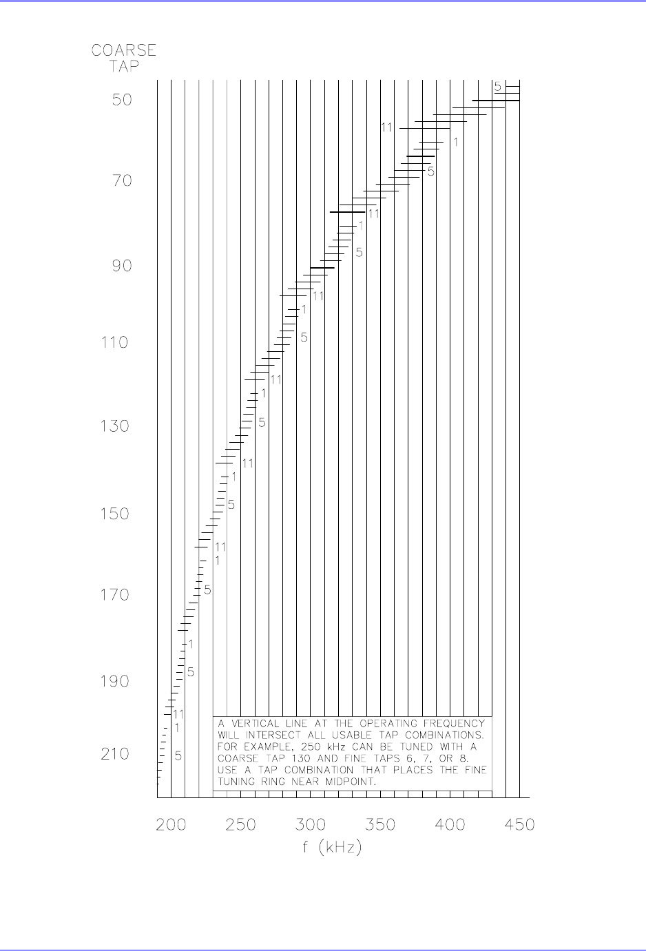
SOUTHERN AVIONICS COMPANY
SE125 Installation and Setup 9-7Coupler Setup
SDE20050 Rev B
Figure 9-3. Mast Antenna Tuned For 190-415 kHz
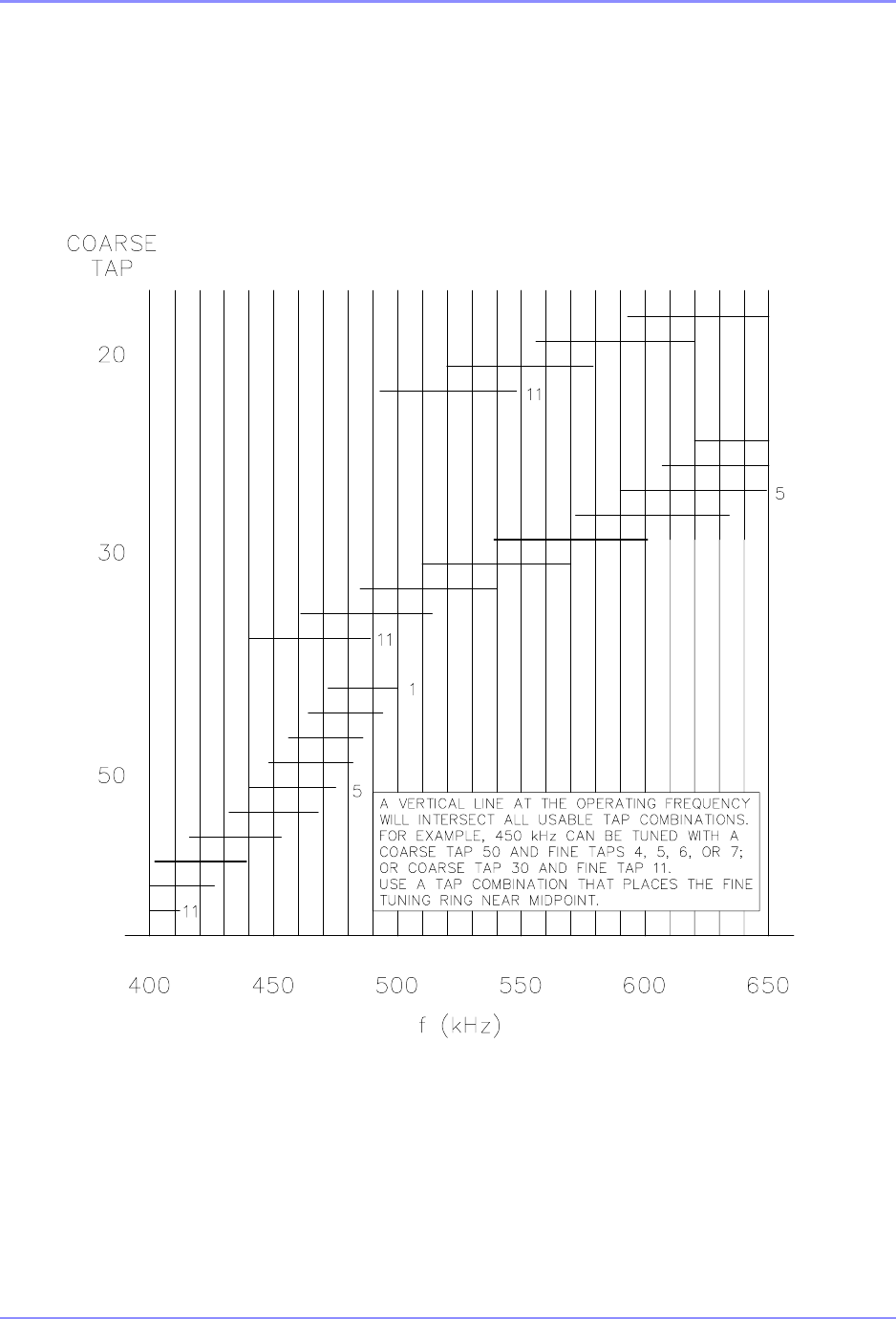
SOUTHERN AVIONICS COMPANY
SE125 Installation and Setup9-8 Coupler Setup
SDE20050 Rev B
Figure 9-4. Mast Antenna Tuned For 415-625 kHz
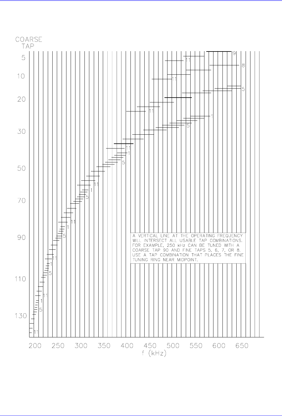
SOUTHERN AVIONICS COMPANY
SE125 Installation and Setup 9-9Coupler Setup
SDE20050 Rev B
Figure 9-5. DPA/50 Foot Guyed Mast Antenna
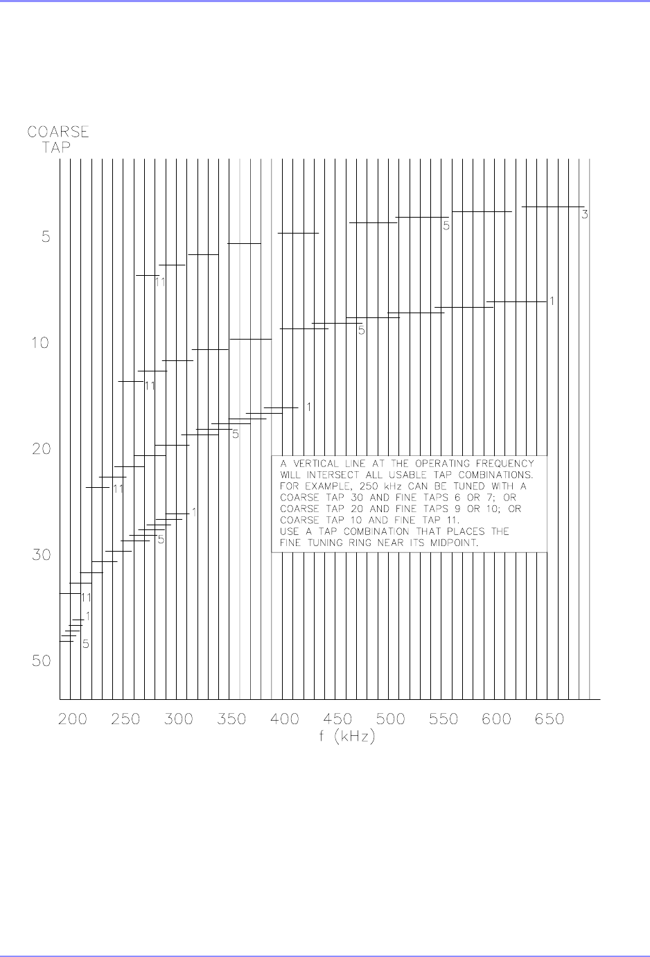
SOUTHERN AVIONICS COMPANY
SE125 Installation and Setup9-10 Coupler Setup
SDE20050 Rev B
Figure 9-6. Symmetrical “T” Antenna
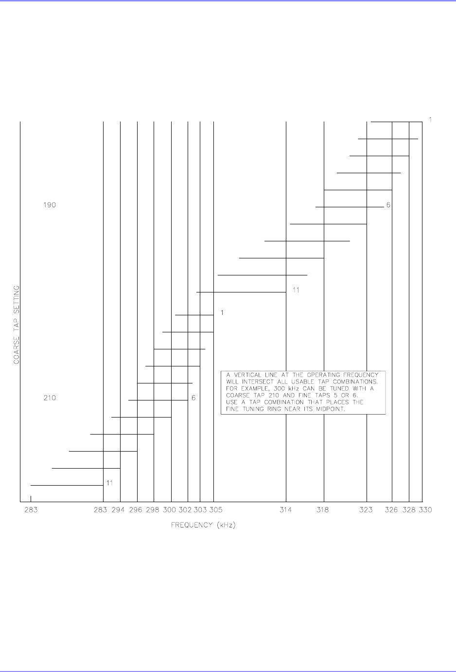
SOUTHERN AVIONICS COMPANY
SE125 Installation and Setup 9-11Coupler Setup
SDE20050 Rev B
Figure 9-7. Whip Antenna Tuned For 283-330 kHz
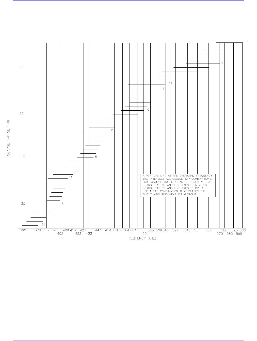
SOUTHERN AVIONICS COMPANY
SE125 Installation and Setup9-12 Coupler Setup
SDE20050 Rev B
Figure 9-8. Whip Antenna Tuned For 360-600 kHz
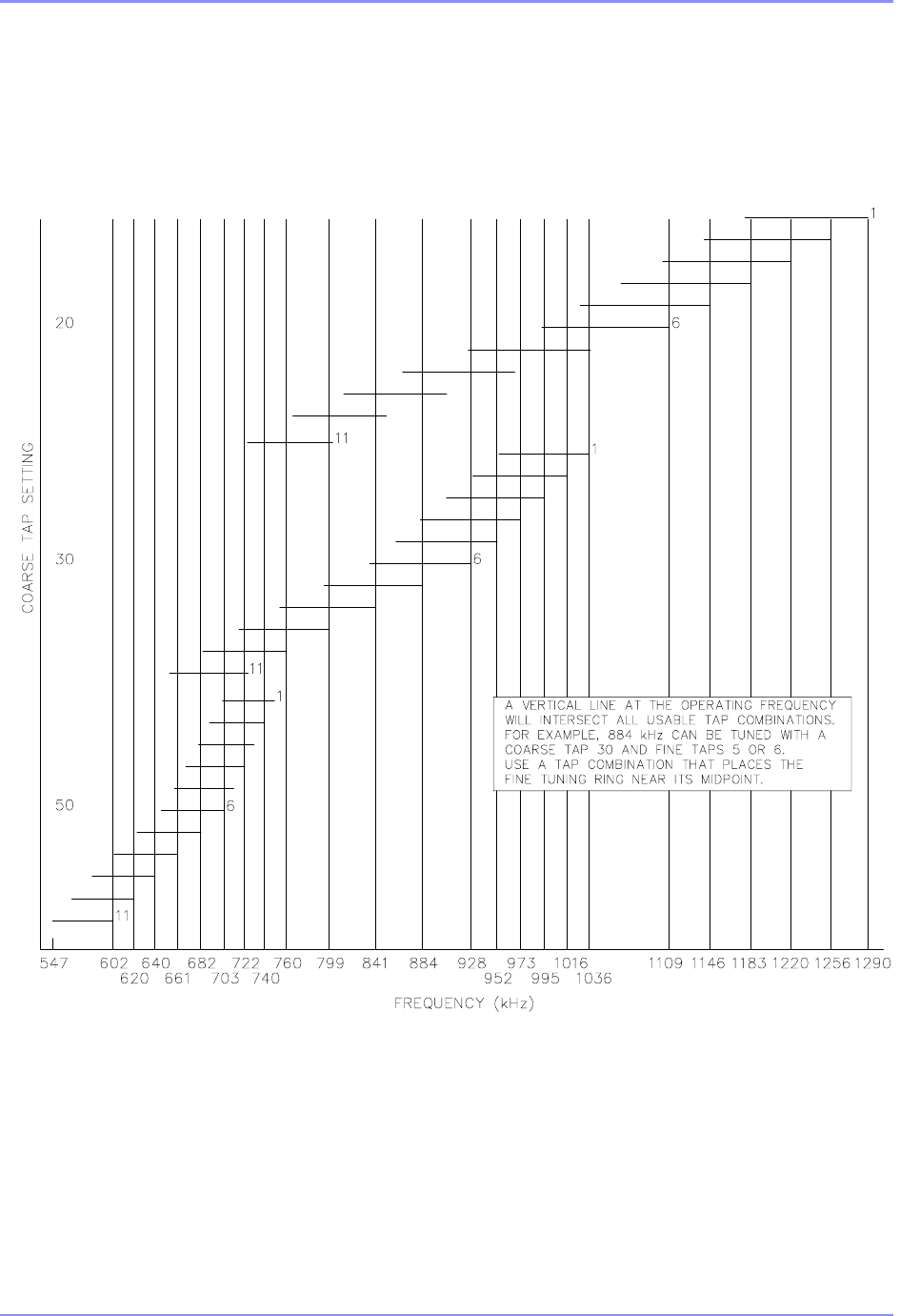
SOUTHERN AVIONICS COMPANY
SE125 Installation and Setup 9-13Coupler Setup
SDE20050 Rev B
Figure 9-9. Whip Antenna Tuned For 547-1290 kHz
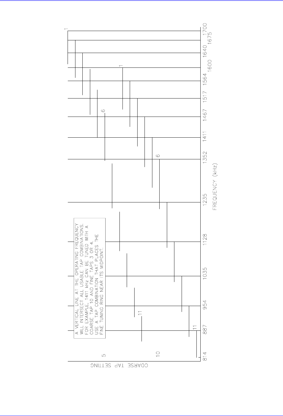
SOUTHERN AVIONICS COMPANY
SE125 Installation and Setup9-14 Coupler Setup
SD107001 Rev 1
Figure 9-10. Whip Antenna Tuned For 814-1700 kHz

SOUTHERN AVIONICS COMPANY
SE125 Installation and Setup 9-15Coupler Setup
9.4 Antenna Theory
The range of a beacon and antenna depends on many variables and cannot be guaranteed. The
field strength can be calculated if the ground conductivity is known, but the field strength needed
depends on background environmental noise which depends on location. A field strength of
70uV/m is generally adequate in the United States and Europe but may not be sufficient in
latitudes between 30 degrees N and 30 degrees S.
9.4.1 Symmetrical “T” Antenna
A Symmetrical “T” Antenna is recommended for use with a 125 - 250 Watt transmitter if sufficient
land is available. This antenna requires a plot of ground approximately 150 feet by 400 feet for a
60 foot high antenna to 150 feet by 500 feet for a 120 foot high antenna.
The standard Symmetrical “T” Antenna is supported by 60 foot above ground level towers or
poles placed 300 feet apart and has a 55 foot vertical radiator and a 2 wire 280 foot horizontal top
hat. Range depends on the field strength required, the ground condition, and the power radiated.
The power radiated increases with frequency, however, the propagation loss due to ground
condition decreases with frequency. For a 70 uV/m field strength, the range over “good” ground
varies from approximately 60 miles at 190 KHz to 70 miles at 535 KHz with a 50 watt transmitter
and approximately 80 miles at 190 KHz to 90 miles at 535 KHz with a 100 watt transmitter.
A Symmetrical “T” Antenna supported by 90 foot towers has a 85 foot vertical radiator and a 2
wire 280 foot horizontal top hat. Range with this antenna over “good” ground varies from
approximately 90 miles at 190 KHz to 95 miles at 535 KHz with a 50 watt transmitter and from
approximately 105 miles at 190 KHz to 115 miles at 535 KHz with a 100 watt transmitter.
9.4.2 Tower Antenna
A Tower Antenna can be used if sufficient land is not available for a Symmetrical “T” Antenna. A
portion of the top set of guy wires is used to form the top hat for this antenna. A Tower Antenna
is electrically inferior to a Symmetrical “T” Antenna of the same height due to the decreased top
loading. Top loading serves two purposes; decreasing the input reactance and consequently the
voltage on the antenna and increasing the effective height.
A 50 foot tower requires a plot of ground with a radius of 60 feet. Range over “good” ground
varies from approximately 40 miles at 190 KHz to 50 miles at 535 KHz with a 50 watt transmitter
and from approximately 60 miles at 190 KHz to 65 miles at 535 KHz with at 100 watt transmitter.

SOUTHERN AVIONICS COMPANY
SE125 Installation and Setup9-16 Coupler Setup
This page intentionally left blank.

SOUTHERN AVIONICS COMPANY
SE125 Installation and Setup 10-1
10 Antenna Tuning and Matching for PC1000C/3
The objective of this section is to setup the coupler to present a 50 Ohm, minimally reactive load
to the SE Transmitter. To ensure this, the inductance of the coupler should be adjusted so that
the measured PA current and voltage matches the values recorded in step 7.5.11 on page 7-3 as
closely as possible.
10.1
The SE Series transmitter is shipped with the default turn on power output set to Zero Watts. If
the power output has been changed, then connect the SE Transmitter’s RF output to a dummy
load.
Turn the system ON and verify that:
TX1 is set as Primary transmitter
The MODE is set to CARR
The OUTPUT POWER is set to Zero (0) watts into a DUMMY LOAD.
MONITOR is disabled
10.2
After verification, connect the Transmitter RF output coax to the Coupler’s input RF N connector.
(It is assumed here that the coupler control cable has already been connected to the SE
Transmitter according to installation instructions.)
10.3
On the coupler front panel, set the Sense and Speed controls fully clockwise temporarily.
10.4
Set the RF Power Level to approximately 20 Watts, making sure the Coupler TX ON/OFF switch
is ON.
10.5
Check the Reflected Power reading to determine the antenna’s state of tune. A value of 0, or
nearly 0, indicates the antenna is tuned. If it is tuned, go to step 10.10 on page 10-2 to ensure that
the best tap combination has been selected. If not, continue to step 10.6 on page 10-2.

SOUTHERN AVIONICS COMPANY
SE125 Installation and Setup10-2
10.6
Rotate the coupler’s INDUCTANCE from one limit to the other by using the CCW/CW switch
while in manual mode. Monitor the coupler meter tune reading during this process for a change in
reflected power. If a change is seen, place the switch in auto to allow the Autotune to make
adjustments freely and go to step 10.7 on page 10-2.
10.7
Turn the Coupler TX ON/OFF Switch OFF, change the FINE TAPS selector wire to the next lower
setting and repeat step 10.4 on page 10-1 through step 10.6 on page 10-2. If the antenna does
not tune, change the FINE TAPS selector wire to the next higher setting and repeat step 10.4 on
page 10-1 through step 10.6 on page 10-2. Continue this bracketing procedure until the
Autotune motor starts to tune the antenna.
If the FINE TAPS selector is at its lowest setting and it is necessary to decrease the inductance,
change the Coarse Tap to the next lower tap and change the FINE TAPS selector to the highest
setting. If the FINE TAPS selector is on the highest setting and it is necessary to increase the
inductance, change the Coarse Tap to the next higher tap and change the FINE TAPS selector to
the lowest setting. Due to overlap, it may be necessary to change the FINE TAPS selector a few
positions before the inductance will be the same as it was before the Coarse Tap was changed.
10.8
Set the RF Power Level to the transmitter’s maximum rated level. Verify the measured Forward
Power level agrees with this setting. Adjust the Coupler’s front panel Sense control
counterclockwise for autotune stability as necessary. It will be fine set later in this procedure.
10.9
Record the measured Reflected Power level and, then ,turn the Coupler TX ON/OFF Switch
OFF.
10.10
Increase the coupler’s IMPEDANCE selector wire setting by one position, the, turn the Coupler
TX ON/OFF Switch ON. Set the RF Power Level to the transmitter’s maximum rated level, and
verify the measured Forward Power level agrees with this setting.
10.11
Record the current measured Reflected Power level and compare it with the level recorded in
step 10.9 on page 10-2. If the current level is greater than the recorded level, turn the Coupler
TX ON/OFF Switch OFF and decrease the IMPEDANCE selector wire setting by two positions
then turn the Coupler TX ON/OFF Switch ON. If the current level is less than the recorded level,

SOUTHERN AVIONICS COMPANY
SE125 Installation and Setup 10-3
turn the Coupler TX ON/OFF Switch OFF and increase the IMPEDANCE selector wire setting by
one position.
10.12
Repeat step 10.9 on page 10-2 through step 10.11 on page 10-2 until the IMPEDANCE selector
setting is found that gives the lowest Reflected Power level and results in a PA current and
voltage close to that recorded in step 7.5.11 on page 7-3.
Normal voltage and current readings at 50 Ohms for each specific transmitter can be found in the
transmitter’s Factory Acceptance Test (FAT) procedure.
10.13
Set the transmitter to operate in Morse Code Identifier (IDENT) Mode.
10.14
Adjust the sense adjustment potentiometer on the coupler Autotune PCB counter clockwise
(CCW) until the Autotune motor begins to chatter, then adjust it back clockwise until all chattering
stops.
10.15
Reduce the Output Power to 0.
10.16
Turn the transmitter OFF (Switch the AC and DC switch to the OFF position.)
10.17
Remove the coupler’s RF output lead where it is attached to the coil.
10.18
Remove the clip from the lead end and trim the wire to the proper length. Ensure at least 3in
(7.6cm) separates the wire from both the coil and the coupler enclosure.
10.19
Dress the wire to avoid sharp bends that may lead to high voltage corona discharge, and solder
the lead to the selected coarse tap on the coil.

SOUTHERN AVIONICS COMPANY
SE125 Installation and Setup10-4
10.20
Replace the Coupler’s front cover panel. The system may now be turned ON and placed into
service at the desired power.

SOUTHERN AVIONICS COMPANY
SE125 Installation and Setup 11-1Closing Up The System
11 Closing Up The System
11.1 Reinstalling/Closing Panels
11.1.1
Reinstall the Power Control Panel and lower transmitter drawers, while ensuring none of the
wiring is pinched or kinked. Fasten the drawer with the mounting screws removed in step 3.1.1
on page 3-1.
11.1.2
Reinstall the transmitter enclosure’s front panel for exterior mounted transmitters to ensure IP-66
rating. Ensure the panel’s fastening screws are torqued sufficiently to seal the enclosure against
water and dust ingress without crushing or deforming the sealing gasket. Begin by starting all
screws and then tighten sequentially from the center outward in steps. The gasket should be
uniformly compressed to approximately one half of its original thickness.
11.1.3
Reinstall the Coupler’s coil access panel that was removed in step 9.1.1 on page 9-1.
11.1.4
Reinstall/close the Coupler enclosure’s front panel that was removed/opened in step 9.1.2 on
page 9-3. Ensure that the screws are torqued sufficiently to seal the enclosure against water and
dust ingress without crushing or deforming the sealing gasket. Begin by starting all screws and
then tighten sequentially from the center outward in steps. The gasket should be uniformly
compressed to approximately one half of its original thickness.
11.2 Conduit Sealing
For an exterior mounted transmitter, seal any open conduits at the bottom of the transmitter’s
enclosure with a silicone sealant to preserve its ingress protection rating.
11.3 Optional RF Weatherproofing
11.3.1
Apply two wraps of electrical tape over the Type N RF connections on both the Transmitter (if
exterior mounted) and the Coupler.
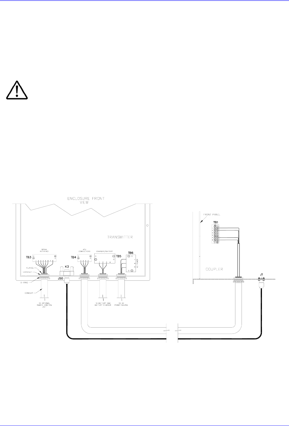
SOUTHERN AVIONICS COMPANY
SE125 Installation and Setup11-2 Closing Up The System
11.3.2
Secondly, apply a layer of Coax-Seal over the tape layers making sure that there are no air
cavities or openings in the wrap.
11.3.3
Finally, apply 2 wraps of electrical tape over the Coax-Seal layer with the final wrap
spiraling UP to minimize water migration. With no further adjustments required, the
system is now ready to be connected to the Beacon Site antenna system. The user
is strongly advised against attempting any system adjustments while it is connected
to the Antenna system, except those allowed by software.
Repeat these steps to seal the cut end of conduit for AC, DC and Serial Interface connections.
SDE33066 Rev D
Figure 11-1. SE Conduit Connection Diagram

SOUTHERN AVIONICS COMPANY
SE125 Installation and Setup 12-1Optional Equipment
12 Optional Equipment
12.1 Audio - SLP10020
12.1.1 General Description
The Audio PCB is an OPTIONAL addition to the standard system which allows the user to
broadcast AWOS announcements. The option is implemented as a daughter board to the Digital
I/O PCB and consists of four sections as follows:
•Audio Input Amplifier
•Automatic Gain Control (AGC)
•Chebyshev Passband Filter
•Voice Detector
The Voice amplifier takes the nominal -17 dBm signal level and amplifies it to a level usable by
the AGC section. The amplifier is common mode balanced with adjustable gain.
The AGC circuit is responsible for modulation limiting. It is adjusted to "capture" the level at -17
dBm and output a constant modulation level to the Digital I/O PWM section up to levels
exceeding +10 dBm. This section prevents inadvertent over modulation of the voice signal. It is
necessary since the Controller has no control over user input.
The Chebyshev Passband filter is designed for 300 to 3000Hz. The output at 4000Hz is down
more than 45 dB, ensuring any out of band audio signals from the operator will not cause
adjacent channel interference.
The Voice Detector has two functions. It detects the presence of an announcement sequence
and automatically attenuates the keying tone level down to 20% modulation. The announcement
level is summed with the keying tone level and set to achieve 95% composite modulation. This
action prevents over modulation and allows the announcement to be heard over the beacon
Morse code IDENT tones. The Voice Detector signals the Controller to temporarily suspend
modulation alarms, since the IDENT tone level is dropped below the alarm threshold.
12.1.2 Detailed Circuit Analysis
General Operation
The Audio PCB is an option that plugs into the Digital I/O PCB allowing an externally applied
signal, usually AWOS, to modulate the transmitter. The plug in provides amplification, automatic
gain control, audio pass-band filtering, and input detection and control.

SOUTHERN AVIONICS COMPANY
SE125 Installation and Setup12-2 Optional Equipment
Input Amplifier
The input differential amplifier takes a 600 Ohm or high impedance input depending on the
setting of JP1 and is made up of U2A, U2B, and U3A.
VOICE+ and VOICE- come in through R7, C5 and R21, C10 to develop a balanced voltage drop
across R13 and R18. R8 and R22 couple this voltage to U2A and U3A. R15, R19, and
potentiometer R24 provide common mode rejection to be fine tuned for minimal line noise. JP2
is used when making this adjustment, and R16 and R25 set the gain of this stage. U2B, along
with the C7, R17 network, and R20, C10 network, provide a flat audio band response. The
output of this stage continues on to the AGC circuitry.
AGC section
The signal AGC_IN is coupled via network C14, R27, and C15 to input calibration potentiometer
R26 where it is coupled, via C16 and R30, to U1C. R28, R33, C18, and R29 provide midpoint
bias for U1C whose gain is set by R36, C21 and R38, C25. A sample of this signal is fed via C22
to AGC circuit U1C, Q2, Q3, and Q4. Q12 acts as a variable resistor at the input of U2A, U1C.
The resistance is controlled by the signal level fed back from U1C pin 1. As the signal level
increases, the gate voltage on Q2 decreases and the resistance decreases, thus lowering the
audio input level to U1C pin 10 and holding the average audio output level constant. U1D boosts
the level of the audio signal, which is output through modulation level adjustment potentiometer
R31 and C19 as VOICE_FLTR_IN. A constant level output is also sent to
VOICE_DETECTOR_IN.
Pass-band Filter section
VOICE_FLTR_IN is coupled into a Chebyshev active pass band filter consisting of U4, U5, and
associated components. Its low end 3dB roll off point is 300Hz, and its high end 3dB roll off point
is 3000Hz, with sufficient attenuation to meet or exceed FCC requirements. The detailed theory
of operation of multi-stage active filters is beyond the scope of this manual and best left to a
textbook on the subject. The output of this stage is called VOICE_FLTR_OUT.
Voice Detector Section
The voice detector’s purpose is to notify the Controller that a voice announcement sequence is
beginning. This process automatically attenuates the normal IDENT output to allow clear
reception of the message and prevents over modulation. A sample of the AGC output is routed
as VOICE_DETECTOR_IN via C2 to buffer U1A. CR1 and C3, R4 convert the audio to a DC
level. When this level is enough to over come the bias on U1B pin 6, the output goes high
causing Q1 to virtually short one end of potentiometer R2 to ground. The adjustable leg of the
potentiometer leaves the board as VOICE_DETECT and connects to the TONE input line on the
Digital I/O PCB. Therefore, R2 becomes a shunt to ground, which is adjusted to lower the tone
level appropriately when an AWOS announcement is input. Buffer U3B provides an additional
level shifted output called VOICE_ON, which notifies the Controller external modulation is being
applied.
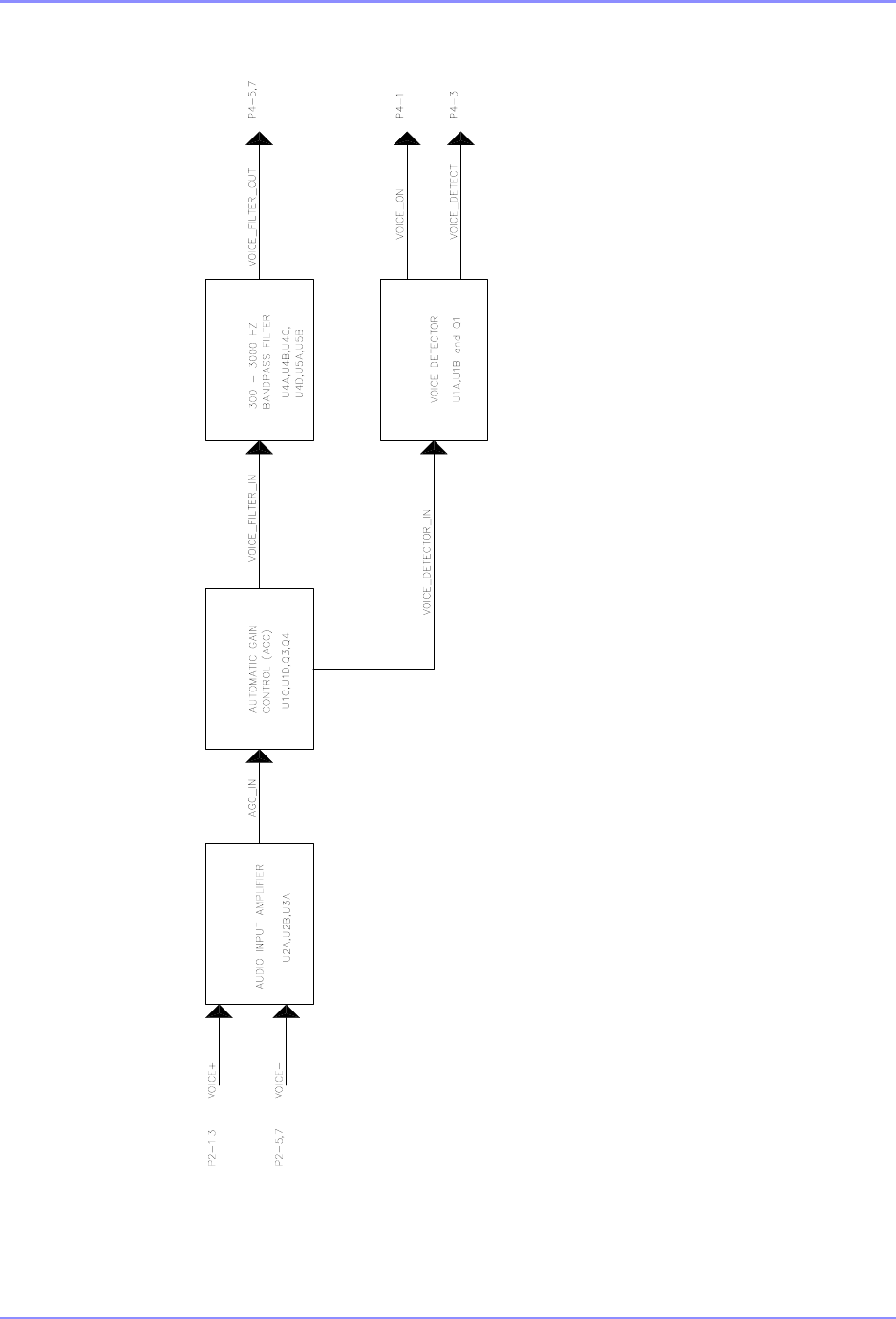
SOUTHERN AVIONICS COMPANY
SE125 Installation and Setup 12-3Optional Equipment
SDB10020 Rev B
Figure 12-1. Audio Block Diagram
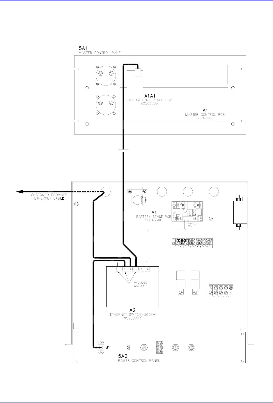
SOUTHERN AVIONICS COMPANY
SE125 Installation and Setup12-4 Optional Equipment
12.2 Ethernet Option
SDE33073 Rev B
Figure 12-2. Ethernet Serial Server Installation Diagram

SOUTHERN AVIONICS COMPANY
SE125 Installation and Setup 12-5Optional Equipment
12.3 Ethernet to Land line Dial-up
Intended use – This configuration is only intended to allow the end user access to the SE Series
Transmitter’s embedded Web Server via a dial up telephone network modem.
This modem is a Remote Access Switch that combines a telephone modem with a 5 port
Ethernet managed switch. This powerful combination allows you to easily and securely access
your Ethernet network from any remote location over standard telephone lines. When dialed, the
SE Transmitter will answer automatically. For other applications see www.sixnet.com/
department/ethernet-switches-faqs-158.cfm)
NOTE: The SE Transmitter will not automatically call out when a fault occurs.
Requirements
•Laptop with an internal modem, Ethernet capabilities, Microsoft Windows XP or later and
Internet Web Browser installed
•An available Telephone Network
•Telephone cable between laptop and telephone network
•1- SIXNET CD with Quick Guide and Manuals (provided)
•1- Ethernet Cable (6-FT provided)
•1-24VDC Power Supply (provided)
•1- Din Rail (provided)
How to Configure a Switch as a Server
1. Connect the laptop to the Ethernet Dial-Up Modem using the Ethernet cable provided using
either of ports 1 to 5. (Default Port 5)
2. Configure the Modem using the following steps from SLX-5MS-MDM-Tutorial.pdf available at
www.sixnet.com/department/ethernet-switches-faqs-158.cfm.
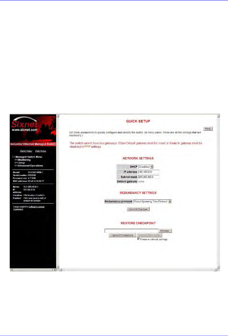
SOUTHERN AVIONICS COMPANY
SE125 Installation and Setup12-6 Optional Equipment
Configuring an SLX-5MS-MDM Switch as a Server
The SLX-5MS-MDM switch, as the server, must assign an IP address to the PC when it dials in.
To configure the SLX-5MS-MDM switch, you must define an IP address that is not being used on
the SLX-5MS-MDM switch’s LAN. You must then create a list of authorized remote users so that
only remote users from that list are able to connect to the remote network.
To configure an SLX-5MS-MDM switch as a server, do the following:
1. Click on Quick Setup from the SLX-5MS-MDM switch’s Web user interface to display the
System Settings/Quick Setup page.
2. Assign an IP address to the SLX-5MS-MDM switch (see the screen shot below).
3. From the Managed Switch menu, choose Setup>Modem Access Settings>PPP Settings to
display the PPP Settings page. Set the PPP mode of the SLX-5MS-MDM switch to Server.
4. In the PPP Server Settings, set the Client IP to the IP address of the Windows PC dialing in.
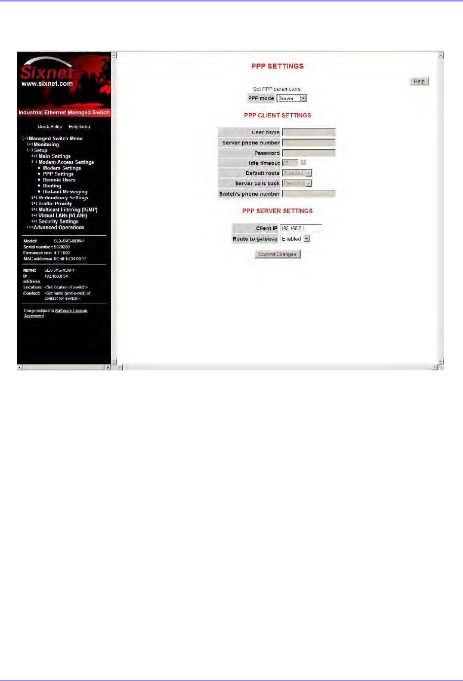
SOUTHERN AVIONICS COMPANY
SE125 Installation and Setup 12-7Optional Equipment
5. Finally, click on Remote Users to add a list of remote users that are authorized to dial in and
access the remote devices. In the screen shot shown below, the default User name of
PPPLink and password Link2Sixnet is used.
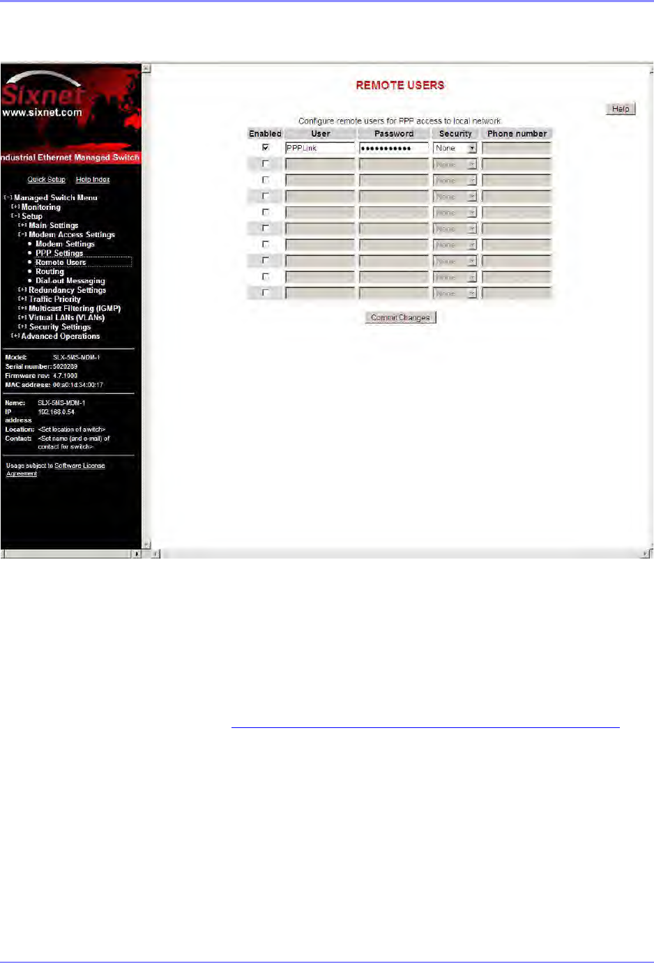
SOUTHERN AVIONICS COMPANY
SE125 Installation and Setup12-8 Optional Equipment
Connection Detail
Configure the system as shown in the connection detail below. The modem must be connected
to the SE Series Transmitter via the Ethernet cable provided and the modem connected to the
dedicated phone line as shown in Figure 12-3. "Ethernet to Land line Dial-Up,”on page 12-9.
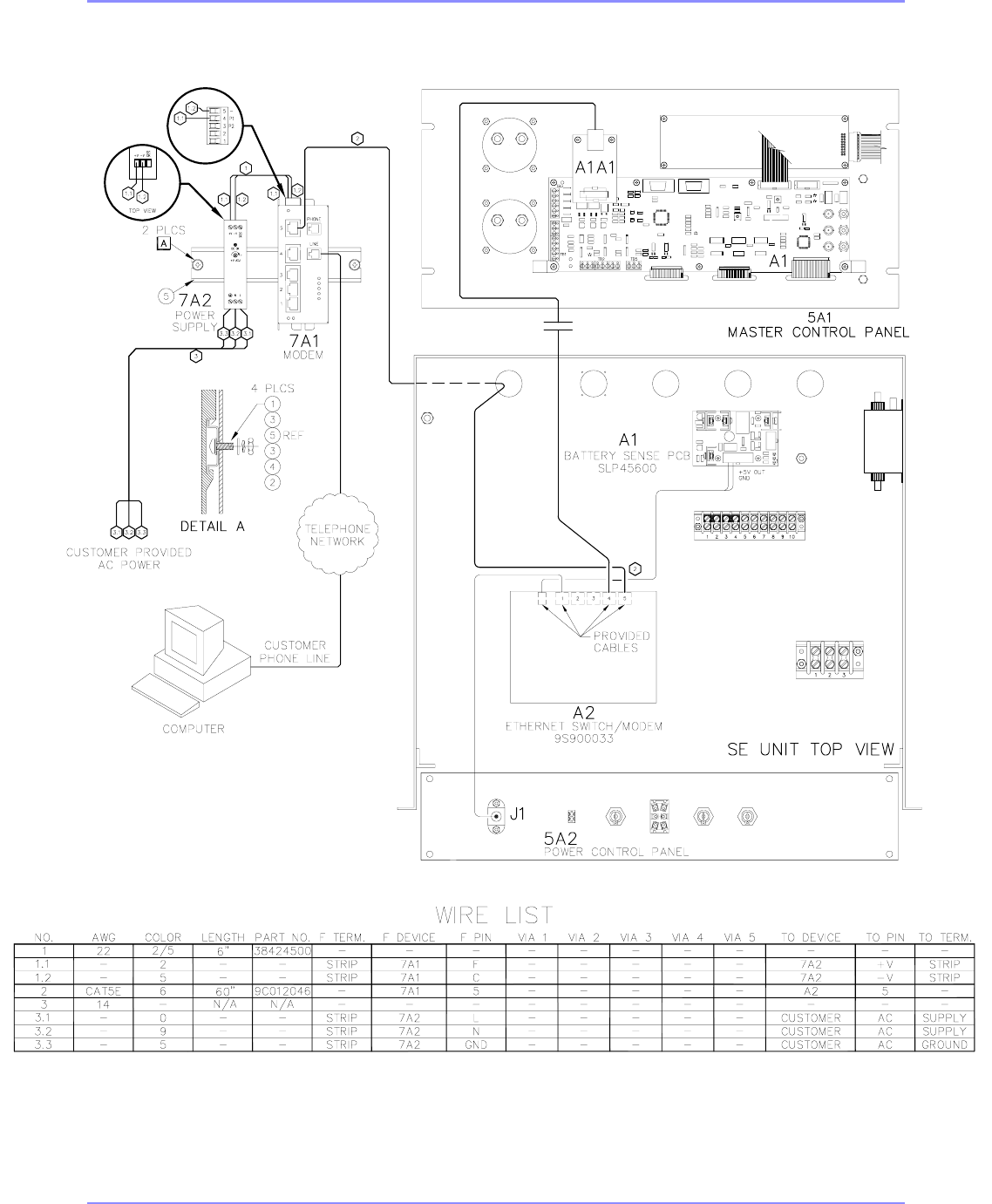
SOUTHERN AVIONICS COMPANY
SE125 Installation and Setup 12-9Optional Equipment
SAF83314 Rev A
Figure 12-3. Ethernet to Land line Dial-Up

SOUTHERN AVIONICS COMPANY
SE125 Installation and Setup12-10 Optional Equipment
How to Configure a Microsoft Windows PC as a Client
Note: In this section you will configure a User Name and Password needed in a subsequent step.
Configuring a Microsoft Windows PC as a Client
To configure Microsoft Windows as a client, you must have a modem installed. If you need to
install a modem, see the user manual of your modem for installation instructions. Then do the
following to create a dial-up connection:
1. From the Windows Start menu, click on the Control Panel, and double-click on Network
Connections. The Network Connections window displays on the screen.
2. Under Network Tasks, click Create a new connection to open the New Connection Wizard.
Click Next.
3. Select Connect to the network at my workplace, and then click Next.
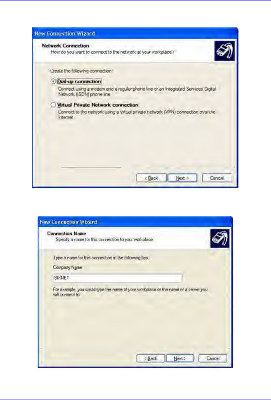
SOUTHERN AVIONICS COMPANY
SE125 Installation and Setup 12-11Optional Equipment
4. Select Dial-up connection, and then click Next.
5. Enter the name to use for the connection. In this case we will use Sixnet. Click Next.
6. Enter the phone number of the phone line that the ET/SLX-5MS-MDM switch is connected to
(the phone number is 5554444 in this case). Click Next.

SOUTHERN AVIONICS COMPANY
SE125 Installation and Setup12-12 Optional Equipment
7. Select the availability of the connection. Click Next.
8. Click Finish to create the connection and exit the New Connection Wizard. A connect
window displays on the screen.
9. Enter a user name and password from the Remote Users page of the ET/SLX-5MS-MDM
switch that is being called. In this case the default user name PPPLink and password
Link2Sixnet are used.
10. Click Dial to initiate the call.
11. When the above configurations are complete, record the SE Transmitter’s IP Address found
in the Network IP configuration section of the Master Control panel. See section 5 “
Network
Control Program Software (optional)” on page 5-1

SOUTHERN AVIONICS COMPANY
SE125 Installation and Setup 12-13Optional Equipment
Steps to bridge SE Transmitter to Web Watch
•At your laptop, go to the Network Connections window (Start\Connect To\Show all
connections)
•Select one of the dial-up names on the list, then appears the Connect ‘name’ window
•Enter User name and Password
•Type SE system’s telephone number in the dial box
•Select the dial button
•The system should connect within 60 seconds
•When successfully connected, open your Internet Browser and enter the SE Transmitter’s IP
address in the address bar.
The Web Watch window should be displayed as seen in Figure 5-1. "Web GUI Main Window
(Dual system),”on page 5-3 and Figure 5-2. "Web GUI Main Window (Single system),”on
page 5-5.

SOUTHERN AVIONICS COMPANY
SE125 Installation and Setup12-14 Optional Equipment
12.3.1 Parts list - SLF83314
SL83314 Ethernet to Land line Dial-up
REF
DES QTY PART NO. DESCRIPTION
1 2 20005016 SCREW; PAN HEAD PHILLIPS 10-32X1/2 STAINLESS
2 2 21005000 NUT; HEX 10-32 STAINLESS STEEL
3 4 22005000 WASHER; FLAT #10 STAINLESS STEEL
4 2 22015000 WASHER; SPLIT LOCK NO. 10 STAINLESS STEEL
5 2 S1330006 RAIL; 6 3/4"W/ 1/2" X 1/4" MOUNTING SLOTS
W1 6in 38626500 WIRE, TWISTED PAIR 18 AWG RED-GREEN
W2 19C012046 CABLE, CAT5E RJ45 MALE/MALE BLUE
7A1 1 9M590004 MODEM, FIVE PH ETHERNET 10/100 LAND-LINE DIAL UP
7A2 19P690011 POWER SUPPLY, 20W SINGLE OUTPUT INDUSTRIAL DUAL

SOUTHERN AVIONICS COMPANY
SE125 Installation and Setup 12-15Optional Equipment
12.4 Multi-Mode Ethernet to Fiber Converter -
SLF83303/SLF83308
A Fiber Optic Converter is combined with an internal Ethernet bridge to allow connection of the
SE Series Transmitter’s embedded serial server program with a remote computer utilizing a fiber
medium at a distance of up to 1.24mi (2km) for Multi-mode operation and 12.4mi (20km) for
Single-mode operation. Two identical converters are required in order to communicate data
between the Transmitter and an Ethernet ready computer.
Requirements
•Laptop with Microsoft Windows XP or later, Ethernet capabilities and Internet Web
Browser installed
•Fiber Optic Cable pair:
•Terminations: SC/UPC SM Male Connectors
•Size: 62.5/125 micron Multi-mode or 9/125 micron Single-mode
•Mode of operation: Multi-mode or Single-mode
•14AWG AC Voltage hookup wire for power supply
•One Quick Installation Guide (provided)
•Two 5ft (1.5m) Ethernet Cables (provided)
•Two 24VDC Power Supplies (provided)
•Two mounting Din Rails (provided)
•Two Multi-mode or Single-mode Ethernet to Fiber Optic Converters (provided)
•Determine the IP address and network Subnet mask of the Transmitter. This is read from
the Transmitter’s Master Control LCD. See section 6.7 “Network IP Configuration” on
page 6-15. You may input your own IP address or use the SAC default address.
Install the Ethernet to Fiber Optic Converters as depicted in the following drawing.
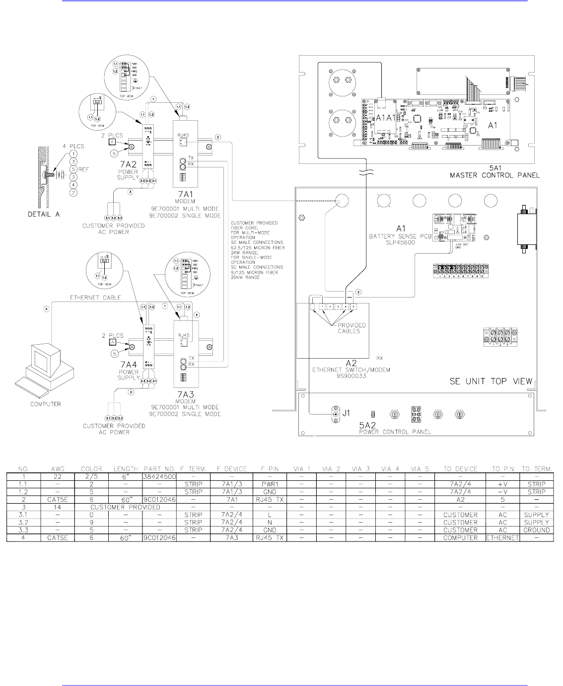
SOUTHERN AVIONICS COMPANY
SE125 Installation and Setup12-16 Optional Equipment
SAF83303 Rev D
Figure 12-4. Multi-Mode Ethernet to Fiber Optics Converter

SOUTHERN AVIONICS COMPANY
SE125 Installation and Setup 12-17Optional Equipment
Fiber Optic Device Settings for EIR-M-SC or EIR-S-SC (see Quick Installation Guide)
1. Power Connections on the removable green terminal block
Connect +V from the Power Supply’s output to PWR1, and jumper PWR1 and PWR2 together
using a piece of the wire provided. If the jumper is not connected, the FAULT Led will remain on.
Also jumper both GND (PWR1) and GND (PWR2) are tied using a piece of the wire provided.
2. 100BaseFX connections
Using two SC male terminated Fiber Optic cables, the Tx (transmit) port of device 1 is connected
in the Rx (receive) port of device 2, and the Rx (receive) port of device 1 is connected to the Tx
(transmit) port of device 2.
3. DIP Switch Settings for both devices
Position no. 1 and 6 are to one (1).
Position no. 2 thru 5 are to zero (0).
Configure Microsoft Windows Network as a Client
1. Energize the Fiber Optic Converter.
2. Connect your laptop to the Fiber Optic Converter using the Ethernet cable provided.
3. At the laptop, select Start → Connect To → Show all connections. The Network
connections window below appears. Select Local Area Connection 2 from the selection
under LAN or High Speed Internet.
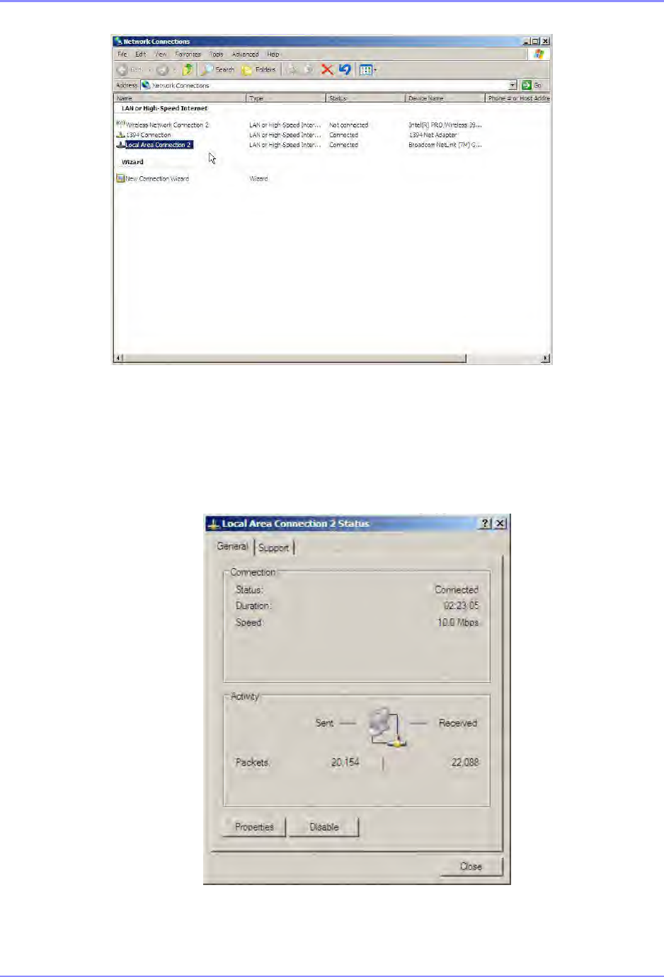
SOUTHERN AVIONICS COMPANY
SE125 Installation and Setup12-18 Optional Equipment
4. The screen displays the Local Area Connection Status window. Select Properties.
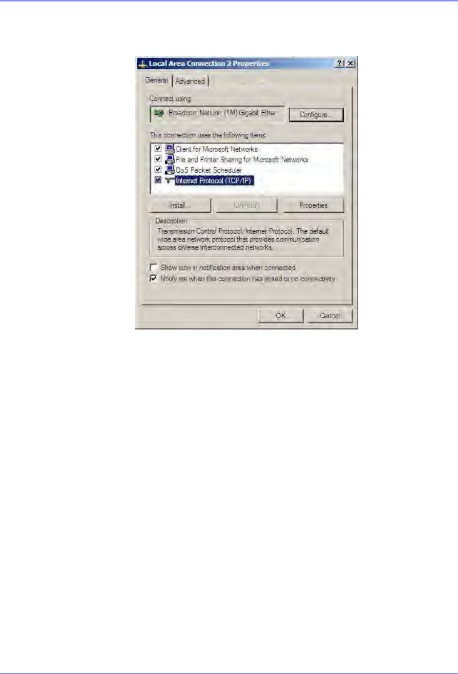
SOUTHERN AVIONICS COMPANY
SE125 Installation and Setup 12-19Optional Equipment
5. The Local Area Connection Properties window appears as below. Select Internet
Protocol (TCP/IP), and then select Properties.
Select Use the following IP address, and then enter the IP address and Subnet mask from the
SE Series Transmitter. Click OK.
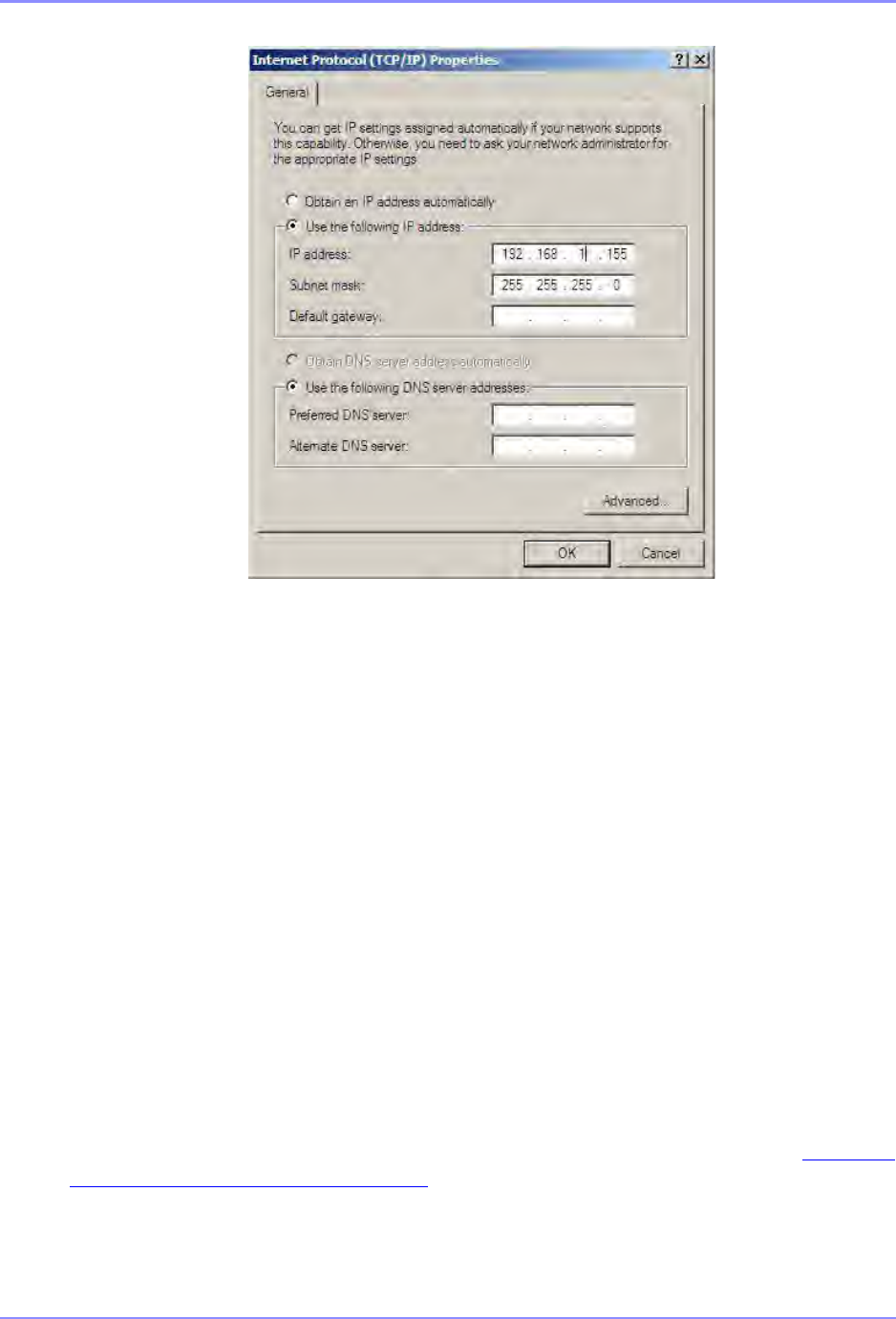
SOUTHERN AVIONICS COMPANY
SE125 Installation and Setup12-20 Optional Equipment
6. Then click OK on the Local Area Connection Properties window.
7. Click Close under the Local Area Connection Status window to exit.
Steps to bridge SE Transmitter to Web Watch
•Energize the SE Transmitter.
•Turn on both Ethernet Fiber Optics converters, and wait approximately 30 seconds for
them to connect. If they do not connect, verify all connections and try again.
•Verify both devices’ LNK/ACT LEDs are flashing while communicating with each other.
•Connect your laptop computer to the remote Fiber Optic converter using the Ethernet
cable provided.
•When successfully connected, open your computer’s Internet Web Browser and enter the
SE Transmitter’s IP address in the address bar.
•You should see the main WEB Watch Program screen described in Section 5.2 “WEB
Watch Program Software” on page 5-1.
•This concludes the installation and initial operation of the Multi-mode and Single-mode
Ethernet to Fiber Optic converters for the SE Series Transmitter System.

SOUTHERN AVIONICS COMPANY
SE125 Installation and Setup 12-21Optional Equipment
12.4.1 Parts list - SLF83303
SLF83308 Multi-Mode Ethernet to Fiber Converter 2KM
12.4.2 Parts list - SLF83308
SLF83308 Multi-Mode Ethernet to Fiber Converter 20KM
REF
DES QTY PART NO. DESCRIPTION
1 4 20005016 SCREW; PAN HEAD PHILLIPS 10-32X1/2 STAINLESS
2 4 21005000 NUT; HEX 10-32 STAINLESS STEEL
3 8 22005000 WASHER; FLAT #10 STAINLESS STEEL
4 4 22015000 WASHER; SPLIT LOCK NO. 10 STAINLESS STEEL
5 2 S1330019 RAIL; 8 1/2"W/ 1/2" X 1/4" MOUNTING SLOTS
W1 1.170
ft 38626500 WIRE, TWISTED PAIR 18 AWG RED-GREEN
W2 19C012046 CABLE, CAT5E RJ45 MALE/MALE BLUE
W4 1 9C012046 CABLE, CAT5E RJ45 MALE/MALE BLUE
7A1 19E700001 CONVERTER, ETHERNET 10/100 TO SINGLE MODE 2KM
7A3 1 9E700001 CONVERTER, ETHERNET 10/100 TO SINGLE MODE 2KM
7A2 19P690011 POWER SUPPLY, 20W SINGLE OUTPUT INDUSTRIAL DUAL
7A4 1 9P690011 POWER SUPPLY, 20W SINGLE OUTPUT INDUSTRIAL DUAL
REF
DES QTY PART NO. DESCRIPTION
1 4 20005016 SCREW; PAN HEAD PHILLIPS 10-32X1/2 STAINLESS
2 4 21005000 NUT; HEX 10-32 STAINLESS STEEL
3 8 22005000 WASHER; FLAT #10 STAINLESS STEEL
4 4 22015000 WASHER; SPLIT LOCK NO. 10 STAINLESS STEEL
5 2 S1330019 RAIL; 8 1/2"W/ 1/2" X 1/4" MOUNTING SLOTS
W1 1.170
ft 38626500 WIRE, TWISTED PAIR 18 AWG RED-GREEN
W2 19C012046 CABLE, CAT5E RJ45 MALE/MALE BLUE
W4 1 9C012046 CABLE, CAT5E RJ45 MALE/MALE BLUE
7A1 19E700002 CONVERTER, ETHERNET 10/100 TO SINGLE MODE 20KM

SOUTHERN AVIONICS COMPANY
SE125 Installation and Setup12-22 Optional Equipment
7A3 1 9E700002 CONVERTER, ETHERNET 10/100 TO SINGLE MODE 20KM
7A2 19P690011 POWER SUPPLY, 20W SINGLE OUTPUT INDUSTRIAL DUAL
7A4 1 9P690011 POWER SUPPLY, 20W SINGLE OUTPUT INDUSTRIAL DUAL
REF
DES QTY PART NO. DESCRIPTION

SOUTHERN AVIONICS COMPANY
SE125 Installation and Setup 12-23Optional Equipment
12.5 Ethernet Leased Line Modem- SLF83301
A Leased Line Modem, combined with an internal Ethernet bridge, allows connection of the SE
Transmitter to a remote located computer via a TELCO Network. Two identical modems are
required for proper communication of data over telephone line or copper wires extended between
the user’s computer and the SE Transmitter.
Requirements
•Laptop with Microsoft Windows XP or later, Ethernet capabilities and Internet Web Browser
installed
•Telephone Line or Copper wires
•One User Guide (provided or http://www.mulogic.com/llm-336-eth.html)
•Two 5ft (1.5m) Ethernet Cables (provided)
•Two Ethernet to Leased Line modems (provided)
•Two 24VDC Power Supplies (provided)
•Two Din Rails (provided).
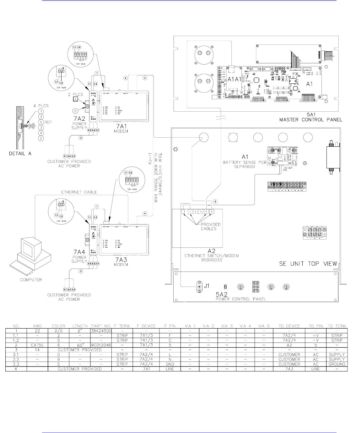
SOUTHERN AVIONICS COMPANY
SE125 Installation and Setup12-24 Optional Equipment
SAF83301 Rev E
Figure 12-5. Leased Line Modem

SOUTHERN AVIONICS COMPANY
SE125 Installation and Setup 12-25Optional Equipment
Steps to Configure the Local Modem at the SE Transmitter
Connect the modems to the transmitter, remote computer and TELCO phone line as shown in
the connection diagram.
Dip-switch 1 (DS1) settings (shipped with default baud: 33.6 kbit/s):
1. Off (UP)
2. Off (UP)
3. Off (UP)
4. Off (UP)
5. On (DOWN)
6. Off (UP)
7. Off (UP)
8. Off (UP).
Dip-switch 2 (DS2) settings:
1. Off (UP)
2. On (DOWN) for 2-wire operation
3. Off (UP)
4. Off (UP)
5. Off (UP)
6. Off (UP)
7. On (DOWN) for Originate mode
8. Off (UP).

SOUTHERN AVIONICS COMPANY
SE125 Installation and Setup12-26 Optional Equipment
12.5.1
How to Configure the Remote Modem at the user’s location (Client)
Dip-switch 1 (DS1) settings (shipped with default baud: 33.6 kbit/s)
1. Off (UP)
2. Off (UP)
3. Off (UP)
4. Off (UP)
5. On (DOWN)
6. Off (UP)
7. Off (UP)
8. Off (UP)
Dip-switch 2 (DS2) settings
1. Off (UP)
2. On (DOWN) for 2-wire operation
3. Off (UP)
4. Off (UP)
5. Off (UP)
6. Off (UP)
7. Off (UP) for Answer mode
8. Off (UP)
When the above settings are complete, record the SE Transmitter’s IP address and Netmask
contained in the network IP configuration under the Transmitter’s Master Control panel. See
section 6.7 “Network IP Configuration” on page 6-15.
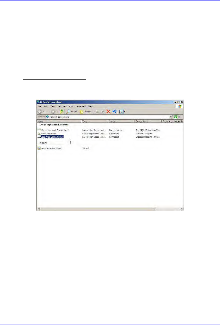
SOUTHERN AVIONICS COMPANY
SE125 Installation and Setup 12-27Optional Equipment
12.5.2
How to configure Microsoft Windows Network as a Client
1. Energize the remote Leased Line Modem.
2. Connect your laptop to the Leased Line modem using the Ethernet cable provided.
3. At the laptop, select Start → Connect To → Show all connections. The Network
connections window below appears. Select Local Area Connection 2 from the selection
under LAN or High Speed Internet.
4. The screen displays the Local Area Connection Status window. Select Properties.
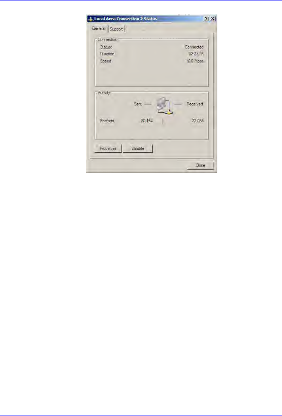
SOUTHERN AVIONICS COMPANY
SE125 Installation and Setup12-28 Optional Equipment
5. The Local Area Connection Properties window appears as below. Select Internet
Protocol (TCP/IP), and then select Properties.
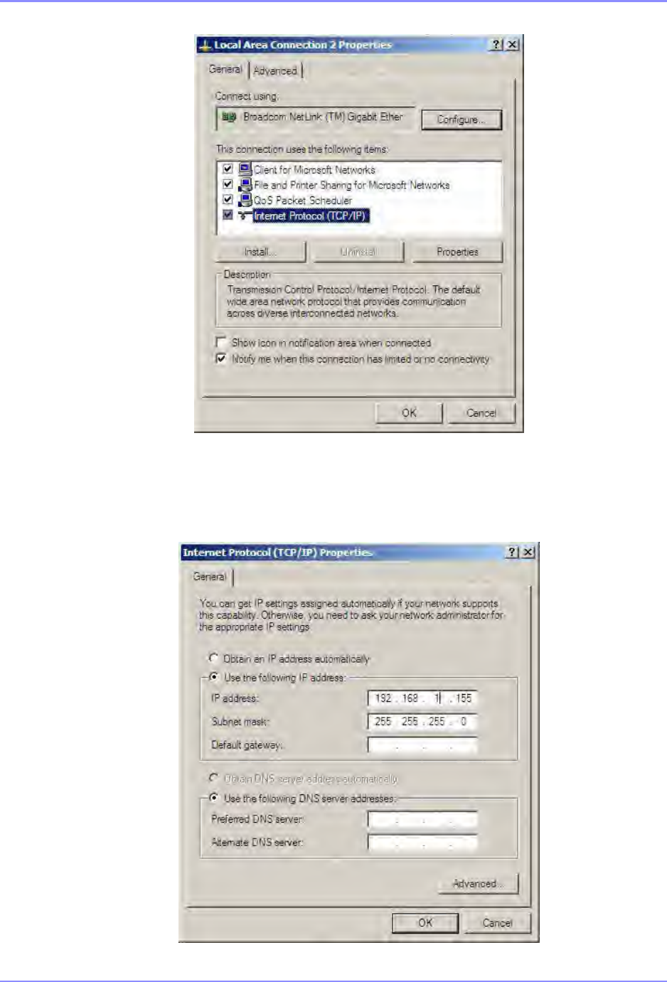
SOUTHERN AVIONICS COMPANY
SE125 Installation and Setup 12-29Optional Equipment
Select Use the following IP address, and then enter the IP address and Subnet mask from the
SE Series Transmitter. Click OK.

SOUTHERN AVIONICS COMPANY
SE125 Installation and Setup12-30 Optional Equipment
6. Then click OK on the Local Area Connection Properties window.
7. Click Close under the Local Area Connection Status window to exit.
Steps to bridge SE Transmitter to Web Watch
•Energize the SE Transmitter.
•Turn on both Ethernet Leased Line modems, and wait approximately 30 seconds for them
to connect. If they do not connect, verify all connections and try again.
•Verify both devices’ LNK LEDs are flashing while communicating with each other.
•Connect your laptop computer to the remote Leased Line modem (above) using the
Ethernet cable provided.
•When successfully connected, open your computer’s Internet Web Browser and enter the
SE Transmitter’s IP address in the address bar.
•See the main WEB Watch Program screen described in Section 5.2 “WEB Watch
Program Software” on page 5-1.

SOUTHERN AVIONICS COMPANY
SE125 Installation and Setup 12-31Optional Equipment
12.5.3 Parts list - SLF83301
SLF83301 Leased line modem
REF
DES QTY PART NO. DESCRIPTION
1 4 20005016 SCREW; PAN HEAD PHILLIPS 10-32X1/2 STAINLESS
2 4 21005000 NUT; HEX 10-32 STAINLESS STEEL
3 8 22005000 WASHER; FLAT #10 STAINLESS STEEL
4 4 22015000 WASHER; SPLIT LOCK NO. 10 STAINLESS STEEL
5 2 S1330019 RAIL; 8 1/2"W/ 1/2" X 1/4" MOUNTING SLOTS
W1 12in 38626500 WIRE, TWISTED PAIR 18 AWG RED-GREEN
W2 19C012046 CABLE, CAT5E RJ45 MALE/MALE BLUE
W4 1 9C012046 CABLE, CAT5E RJ45 MALE/MALE BLUE
7A1 19E700003 ETHERNET 10/100 SINGLE OUTPUT INDUSTRIAL
7A2 1 9E700003 ETHERNET 10/100 SINGLE OUTPUT INDUSTRIAL
7A3 19P690011 POWER SUPPLY, 20W SINGLE OUTPUT INDUSTRIAL DUAL
7A4 1 9P690011 POWER SUPPLY, 20W SINGLE OUTPUT INDUSTRIAL DUAL

SOUTHERN AVIONICS COMPANY
SE125 Installation and Setup12-32 Optional Equipment
12.6 Ethernet Extender - SLF83315
Two Ethernet Extenders are combined with an internal Ethernet bridge to allow series extension
of the SE Series Transmitter’s Ethernet communication network via a RJ-11 terminated TELCO
Network cable (see Quick Start Guide provided for detailed description).
Requirements:
•Laptop with Microsoft Windows XP or later, Ethernet capabilities and Internet Web Browser
installed
•One Pair of TELCO Network cable with RJ-11 termination
•Two AC to DC Power Adaptors (provided)
•One Quick Start Guide (provided)
•Two 5ft (1.5m) Ethernet Cables (provided)
•Determine the IP address and network Subnet mask of your SE Series Transmitter. This is
read from the Transmitter’s Master Control LCD. See Section 6.7 “Network IP Configuration”
on page 6-15. You may input your own IP address or use the SAC default address.
Install the Ethernet Extenders as depicted in the following drawing:
Power Connections:
The power adaptor (provided) plugs into the power port of each Ethernet Extender.
DIP Switch Settings:
Extender 1 at the SE Transmitter location must be set to local (Loc).
Extender 2 at the laptop location is set to remote (Rmt).

SOUTHERN AVIONICS COMPANY
SE125 Installation and Setup 12-33Optional Equipment
Communication Connections:
For the local Extender, the Ethernet cable connects between one of the ports of the SE
Transmitter’s LAN switch and the Ethernet port of the Ethernet Extender.
For the remote Extender, the Ethernet cable connects between the Ethernet port of your laptop
and the Ethernet port of the Ethernet Extender.
One RJ-11 TELCO Network cable connects between the Line port of the Local Extender and the
Line port of the Remote Extender.
Configure of Microsoft Windows Network as a Client (insert the same write up as the Fiber
Optics section)
Steps to bridge the SE Transmitter to the SE Transmitter’s WEB Watch:
•Energize the SE Transmitter.
•Turn on both Ethernet extenders, and wait approximately 10 seconds for them to connect. If
they do not connect, verify all connections and try again.
•Verify both devices’ LNK/ACT LEDs are flashing while communicating with each other.
•Verify both devices’ Line Speed LEDs are the same number(s).
•Verify the local extender’s LOC LED is on and the remote extender‘s RMT LED is on.
•When successfully connected, open your computer’s Internet Web Browser and enter the SE
Transmitter’s IP address in the address bar.
•See the main WEB Watch Program screen described in Section 5.2 “WEB Watch Program
Software” on page 5-1.
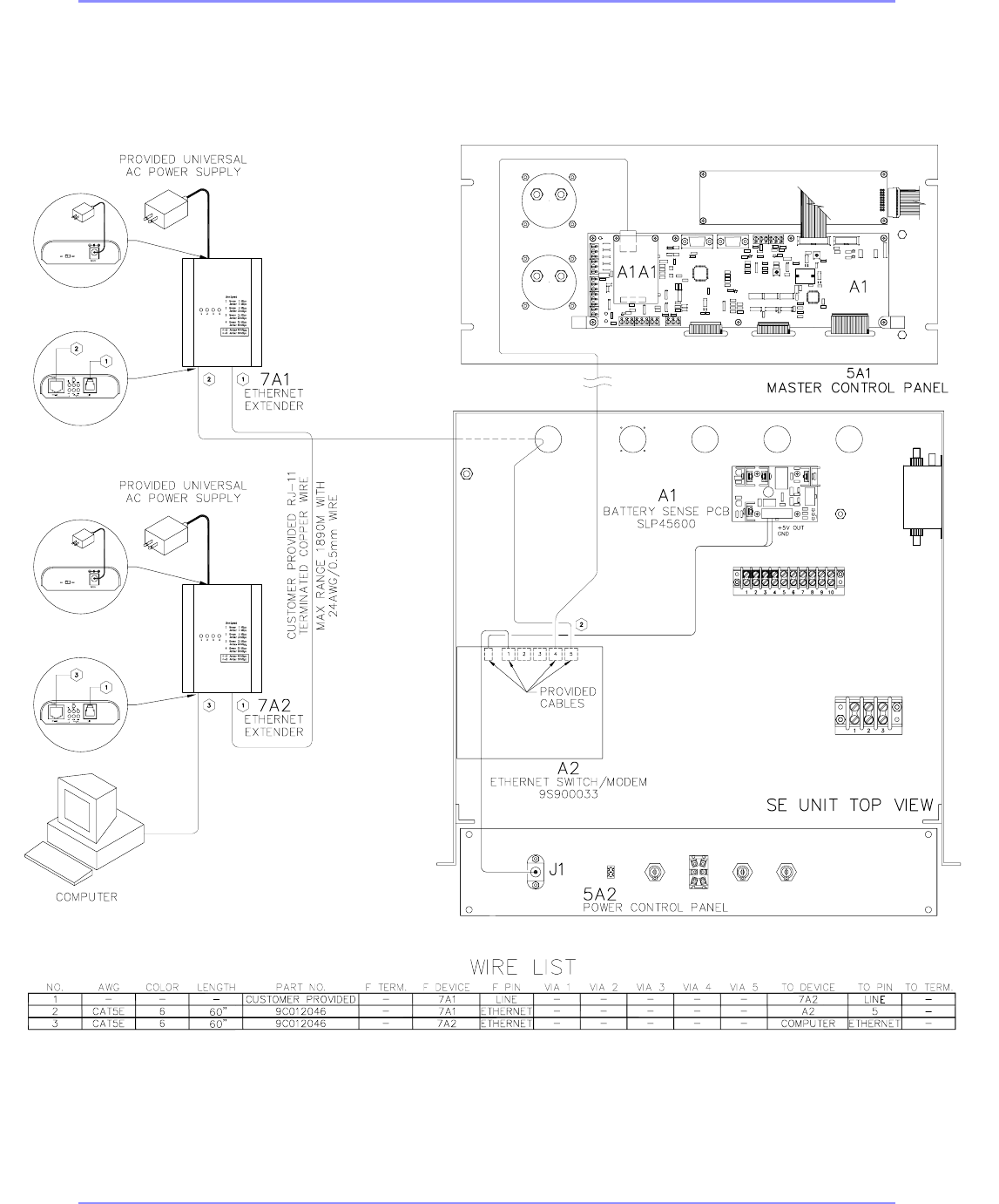
SOUTHERN AVIONICS COMPANY
SE125 Installation and Setup12-34 Optional Equipment
SAF33015 Rev E
Figure 12-6. Ethernet Extender

SOUTHERN AVIONICS COMPANY
SE125 Installation and Setup 12-35Optional Equipment
12.6.1 Parts list - SLF83315
SLF83315 Ethernet extender modem
REF
DES QTY PART NO. DESCRIPTION
W2 19C012046 CABLE, CAT5E RJ45 MALE/MALE BLUE
W4 1 9C012046 CABLE, CAT5E RJ45 MALE/MALE BLUE
7A1 19E700000 ETHERNET COPPER EXTENDER 10/100 Mbps, 6200 FEET
RANGE
7A2 1 9E700000 ETHERNET COPPER EXTENDER 10/100 Mbps, 6200 FEET
RANGE

SOUTHERN AVIONICS COMPANY
SE125 Installation and Setup12-36 Optional Equipment
12.7 Ethernet Radio Link - SLF83304
Introduction: This option is an IP67 rated Industrial Wireless Radio equipped with an Ethernet
bridge allowing the connection of the SE Series Transmitter’s Ethernet port over a wireless radio
medium to a distant Ethernet ready computer or LAN. The wireless transceivers must be the
same model at both NDB and remote sites to allow communication of data over this wireless link.
Requirements:
•Laptop with Microsoft Windows XP or later, Ethernet capabilities and Internet Web
Browser installed.
•Two Industrial Ethernet Wireless Radio.
•Two 5.8GHz, 19dBi Panel Directional Antenna N-Female Connector and Pole Mount
Brackets (provided).
•One N-TRON 702M12-W Software CD with User’s Manual & Installation Guide
(provided).
•Two 24VDC Power Supplies (provided).
•Two Din Rails (provided).
•#2 Phillip’s head (star) screwdriver
•Narrow #1 flat head screwdriver
•10mm nut driver
•13mm nut driver
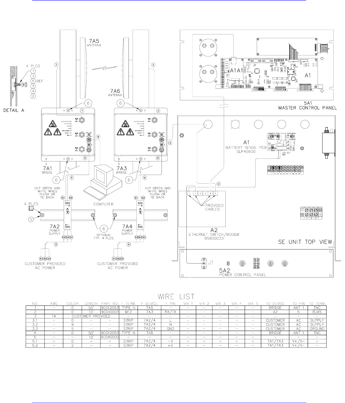
SOUTHERN AVIONICS COMPANY
SE125 Installation and Setup 12-37Optional Equipment
SAF83304 Rev A
Figure 12-7. Ethernet Radio link detail

SOUTHERN AVIONICS COMPANY
SE125 Installation and Setup12-38 Optional Equipment
Note:
Read the User’s Manual & Installation Guide special emphasis is placed on review all safety
warnings prior to beginning this installation.
The 702M12-W Installation:
To install the Wireless Radio mounted to a DIN-Rail, bulkhead or an outdoor pole (see Pages 9 to
11 of the User’s Manual & Installation Guide on the CD provided).
Two options for DIN-Rail installation exist to mount the provided power supplies. Mount the rail
using either reference designator combination (1), (3), (5), (3), (4) and (2); or use the provided
sheet metal/wood screws reference designator (6), as seen in the Radio Link option drawing.
Mount the provided Power Supplies (7A2) and (7A4) to the Din-Rails. Ethernet Bridges (7A1)
and (7A3) should be mounted using sheet metal/wood screws (6). See Antenna mounting
instructions and use hardware provided with the antenna to mount. You will need a 10mm and
13mm socket to tighten antenna hardware.
Applying Power:
The M12A coded power connector is keyed, so a mating connection from the power supply can
only be made when the male and female ends are properly aligned. Connect one cable,
reference designator (5), between power supply (7A2) and Ethernet Bridge (7A1), and connect
one cable, reference designator (5), between power supply (7A4) and Ethernet Bridge (7A3). In
each case cut or tie back the green and white wires. These wires are available for redundant
supply use, see note below.
Notes: (Recommended 24V DC Power Supply provided)
•Only one power supply must be connected for full operation. For redundant power
operation V1 and V2 inputs must be connected to separate DC Voltage sources. The
transmitter will draw current from both sources simultaneously. Use 16-18 gauge wires
when connecting to the power supply.
Ethernet Connections:
Connect wire (6) between Ethernet Bridge (7A1) and the remote computer. Connect wire (2)
between Ethernet Bridge (7A3) and the SE Transmitter’s Ethernet Switch.
Earth Grounding:
See page 16 of the User’s Manual and Installation Guide for proper transmitter grounding.

SOUTHERN AVIONICS COMPANY
SE125 Installation and Setup 12-39Optional Equipment
Troubleshooting:
•Make sure the PWR (Power LED) is ON.
•Make sure you are supplying sufficient current the version chosen.
•Note: The Inrush current will exceed the steady state current by ~2X
•Verify that the LNK/ACT (Link/Activity LED) is ON for the connected port.
•Verify cabling used between SE Transmitter unit and station.
•Verify that cabling is Category 5E or greater for 100Mbit operating.
Wireless Radio Software Configurations:
To Configure the Settings of the Wireless Radio (see Pages 19 thru 55 in the User’s Manual and
Installation Guide). The following topology has been chosen at Southern Avionics Company as
the default: Scenario 1 - Basic Bridge.
Remember: record IP Address and Network Subnet Mask found in the network IP configuration
settings of SE Transmitter’s Master Control pane. See section 5 “
Network Control Program
Software (optional)” on page 5-1 and section 6.7 “Network IP Configuration” on page 6-15.
Device #1 Setting:
Link Setup Label Name Enter
Wireless Mode: AP
SSID: N-TRON
Country Code: United States
802.11 Mode: 11Ng-20MHz
Channel: 10 – 2457MHz
Extension Channel: N/A
Output Power: 12dBm
Network Mode: Bridge
IP Address: 192.168.1.7
Netmask: 255.255.255.0
Gateway: 192.168.1.1
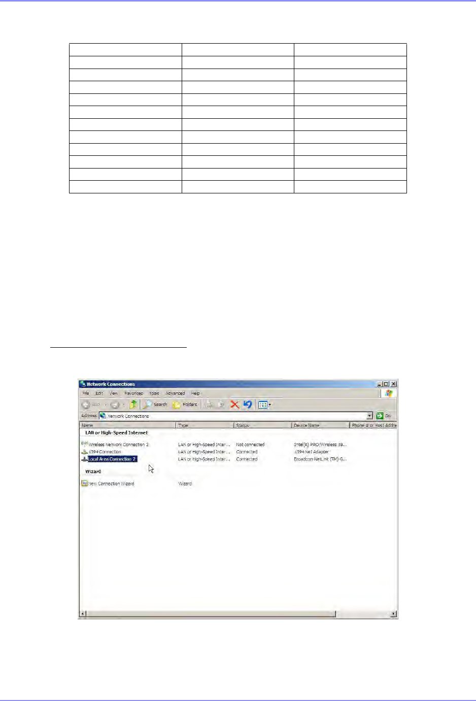
SOUTHERN AVIONICS COMPANY
SE125 Installation and Setup12-40 Optional Equipment
Device #2 Setting:
Configure Microsoft Windows XP Network as a Client
1. Energize the Ethernet Wireless Radio.
2. Connect your laptop to the Wireless Radio using the Ethernet cable provided.
3. At the laptop, select Start → Connect To → Show all connections. The Network
connections window below appears. Select Local Area Connection 2 from the selection
under LAN or High Speed Internet.
Link Setup Label name Enter
Wireless Mode: Station
ESID: N-TRON
Country Code: United States
802.11 Mode: 11Ng-20MHz
Extension Channel: N/A
Output Power: 12dBm
Network Mode: Bridge
IP Address: 192.168.1.8
Netmask: 255.255.255.0
Gateway: 192.168.1.1
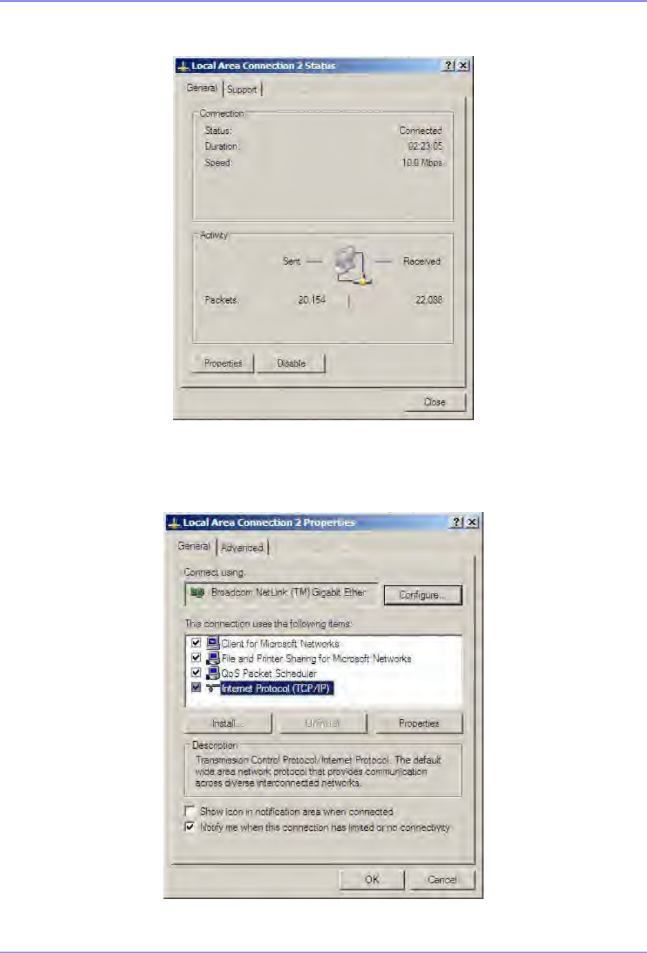
SOUTHERN AVIONICS COMPANY
SE125 Installation and Setup 12-41Optional Equipment
4. The screen displays the Local Area Connection Status window. Select Properties.
5. The Local Area Connection Properties window appears as below. Select Internet
Protocol (TCP/IP), and then select Properties.
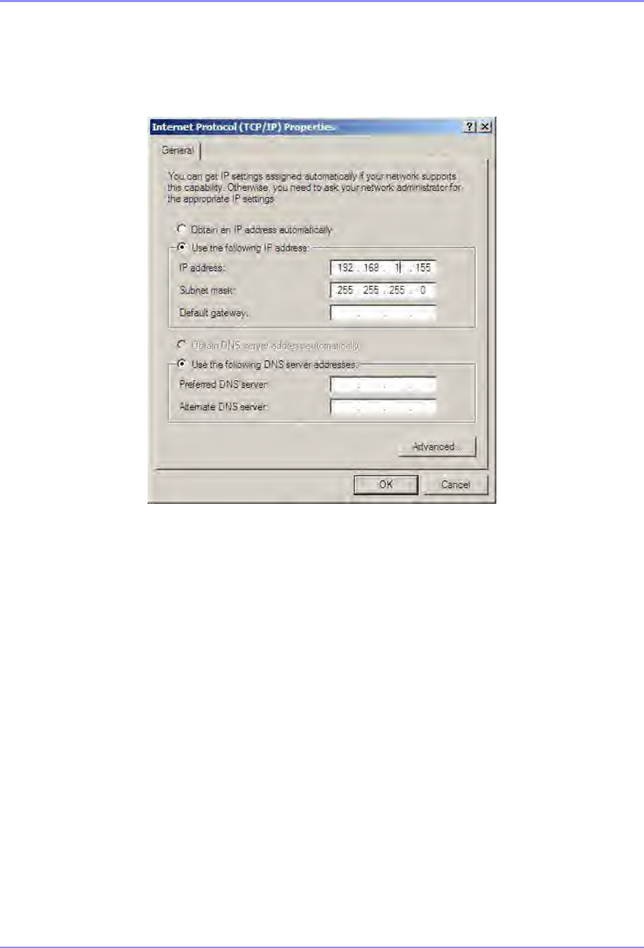
SOUTHERN AVIONICS COMPANY
SE125 Installation and Setup12-42 Optional Equipment
Select Use the following IP address, and then enter the IP address and Subnet mask from
the SE Series Transmitter. Click OK.
6. Then click OK on the Local Area Connection Properties window.
7. Click Close under the Local Area Connection Status window to exit.
Steps to bridge SE Transmitter to Web Watch
•Energize the SE Transmitter.
•Turn on both Ethernet Wireless Radio devices, and wait approximately 30 seconds for
them to connect. If they do not connect, verify all connections and try again.
•Verify both devices’ RADIO ENABLED, and PWR LEDs are ON and the LNK/ACT LED is
flashing while communicating with each other.
•Connect your laptop computer to the remote device (above) using the Ethernet cable
provided.

SOUTHERN AVIONICS COMPANY
SE125 Installation and Setup 12-43Optional Equipment
•When successfully connected, open your computer’s Internet Web Browser and enter the
SE Transmitter’s IP address in the address bar.
•You should see the main WEB Watch Program screen described in Section 5.2 “WEB
Watch Program Software” on page 5-1.

SOUTHERN AVIONICS COMPANY
SE125 Installation and Setup12-44 Optional Equipment
12.7.1 Parts list - SLF83304
SL83304 Ethernet Radio link option
REF
DES QTY PART NO. DESCRIPTION
1 2 20005016 SCREW; PAN HEAD PHILLIPS 10-32X1/2 STAINLESS
2 2 21005000 NUT; HEX 10-32 STAINLESS STEEL
3 4 22005000 WASHER; FLAT #10 STAINLESS STEEL
4 2 22015000 WASHER; SPLIT LOCK NO. 10 STAINLESS STEEL
5 2 S1330006 RAIL; 6 3/4"W/ 1/2" X 1/4" MOUNTING SLOTS
6 8 20095032 SCREW; PAN HEAD SHEET METAL 10X1 STAINLESS
W1 19C012053 CABLE; COAXIAL, TNC REVERSE POLARITY TO TYPE-N MALE
W2 1 9C040001 CABLE; CAT5E, 90 deg, M12 TO RJ45, SHIELDED, 10FT
W4 19C012053 CABLE; COAXIAL, TNC REVERSE POLARITY TO TYPE-N MALE
W5 2 9C040000 CABLE; POWER, 90 deg M12 A-CODED FMLE BARE
W6 19C040001 CABLE; CAT5E, 90 deg, M12 TO RJ45, SHIELDED, 10FT
7A1 1 9E700004 ETHERNET BRIDGE, WIRELESS OUTDOOR, 5.8 GHz mi
RANGE
7A3 19E700004 ETHERNET BRIDGE, WIRELESS OUTDOOR, 5.8 GHz mi
RANGE
7A5 1 9A540005 ANTENNA; N-FEMALE 5.8GHz, 19dBi FLATPANEL
7A6 19A540005 ANTENNA; N-FEMALE 5.8GHz, 19dBi FLATPANEL

SOUTHERN AVIONICS COMPANY
SE125 Installation and Setup 12-45Optional Equipment
12.8 Internal 48VDC Battery Charger - SLF83320
Warning! This battery charger contains an operating voltage selector switch.
Failure to set this switch to the correct position will result in damage to the
charger.
The internal battery charger option provides an IP66 protected battery charger solution for the SE
series transmitter. The charger is rated a 6 Amps, and it is designed to charge any type of lead
acid battery (gel, sealed or wet) to full charge. This option includes a battery charger, front panel,
ON/OFF switch and AC voltage input fusing.
For infield installation: This option requires two holes to be drilled in the enclosure, so hardware
installation must be accomplished according to the provided documentation to ensure IP66
integrity.
Requirements:
•SE Single or Dual Transmitter (provided)
•Internal Battery Charger (provided)
•Installation drawing and hole schedule (provided)
•Necessary wiring, switches, fuses and wire connections (provided)
•#2 Phillips-head screwdriver
•#19 (0.166) drill bit
•11/32” nut driver
•3/8” deep well nut driver
•Wire cutter with 18 and 16 AWG wire strippers
•Heat gun
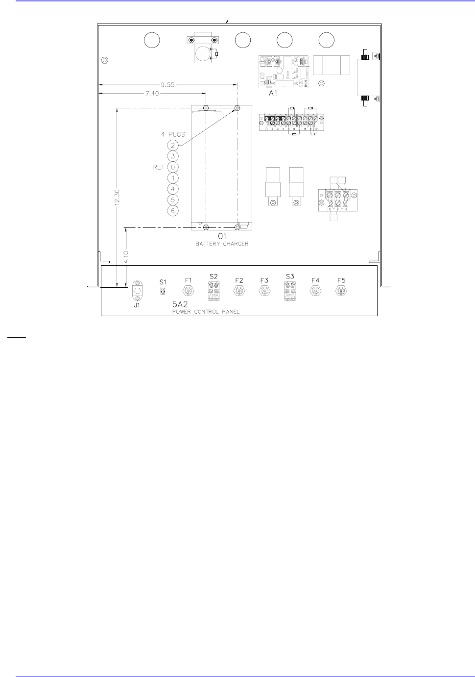
SOUTHERN AVIONICS COMPANY
SE125 Installation and Setup12-46 Optional Equipment
SAF83320 Rev A
Figure 12-8. Internal Battery Charger
Notes:
1. Remove Transmitter drawer(s) and set aside.
2. Remove Power Control Panel and replace with the optional
battery charger’s Power Control Panel (SLM33021)
containing mounting holes for switch S3 and fuses XF4
and XF5.
3. Install switch S3, XF4, XF5, F4 and F5, if not already
installed, and move J1, S1, F1, S2, F2 and F3 from the old
panel to the new.
4. Using a pencil, precision rule and set punch prepare the
drill locations for the battery charger’s mounting holes.
5. After punching the marks set the battery charger over the
marks to verify proper alignment, the charger sets square
and adequate room is available for the AC and DC wires to
lie on either side of the charger.
6. Drill and deburr the holes at the given dimensions starting
with a small drill bit such as 0.104” (#37) followed by the
required 0.166” (#19).
7. Verify the AC input voltage to be used and set the AC
voltage selector switch on the battery charger to either
115VAC or 230VAC.
8. Install the charger’s hardware, as called out, using an
11/32” nut driver and #2 Phillips-head screwdriver.
9. Using the 11/32” nut driver remove the terminal block
covers of TB5 and TB6.
10. According to the wire cut list and wire diagram remove the
three prong plug and trim the outer insulation exposing the
black (W4.1), white (W4.2) and green (W4.3) wires of the
IEC AC Power Cord. Route the black (W4.1) and white
(w4.2) wires to XF4 and XF5 respectively.
11. According to the wire cut list attach the green wire (W3) to
GND1 using a 3/8” nut driver on one end, and solder the
other end of the green wire (W3) to the green wire (W4.3)
of the battery charger’s IEC AC Power Cord.
12. With heat gun activate heatshrink over the green wire’s
solder connection.
13. According to the wire cut list solder the Black (W1) and
White/Black (W2) wires to switch S3 and route to the AC
terminal block TB6-1 and TB6-2 respectively.
14. According to the wire cut list solder the Black (W6) and
White/Black (W7) wires to switch S3 and route to XF4 and
XF5 respectively.
15. According to the wire cut list route the Red (W5.2) and
Black (W5.1) DC wires, permanently attached to the
battery charger, to the DC Terminal Block TB5-1 and TB5-
4 respectively.
16. Tie wrap all wires into place, and remove excess tie wrap
length.
17. With a mirror once again verify the AC input voltage
selector switch on the battery charger is properly set to
either 115VAC or 230VAC.
18. Using the dresser hardware install the new Power Control
Panel.
19. Install the lower transmitter drawer and reconnect all wiring
to its back panel.
20. Install the upper transmitter drawer and reconnect all
wiring to its back panel.
Tools required:
1. 1x #2 Phillips-head screwdriver
2. 1x 11/32” nut driver
3. 1x 3/8” deep well nut driver
4. 18 AWG wire stripper
5. 16 AWG wire stripper
6. 1x wire cutter
7. 1x heat gun
8. 1x mirror
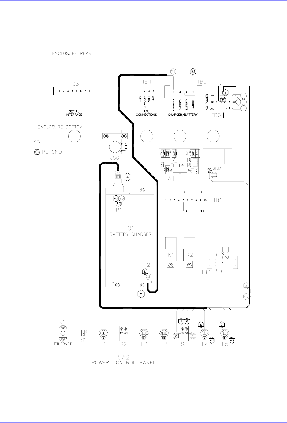
SOUTHERN AVIONICS COMPANY
SE125 Installation and Setup 12-47Optional Equipment
SAF83320 Rev A
Figure 12-9. Internal Battery Charger connection

SOUTHERN AVIONICS COMPANY
SE125 Installation and Setup12-48 Optional Equipment
12.8.1 Parts list - SLF83320
SLF83320 Battery Charger
REF
DES QTY PART NO. DESCRIPTION
1 1 9P690010 BATTERY CHARGER 48VDC, 6AMP CONSTANT CURRENT
2 4 20004016 SCREW; PHP 8-32X1/2 SS
3 4 22304000 WASHER; FLAT NO. 8 .375OD X .030 NYLON
4 8 22004000 WASHER; FLAT NO. 8 SS
5 4 22014000 WASHER; SPLIT LOCK NO. 8 SS
6 4 21004000 NUT; HEX 8-32 SS
7 1 21005000 NUT; HEX 10-32 SS
8 1 22005000 WASHER; FLAT #10 SS(0.203ID X 0.437OD X 0.062TH)18-8SS
9 1 22015000 WASHER; SPLIT LOCK NO. 10 SS
10 1 22025000 WASHER; INTERNAL TOOTH NO. 10 SS
11 1SLM33021 PANEL POWER CONTROL BATTERY CHARGER OPTION
F4 1 9F830081 FUSE, 8 AMP, 250V, 3AG (MDL) SLO-BLO TYPE
F5 19F830081 FUSE, 8 AMP, 250V, 3AG (MDL) SLO-BLO TYPE
HS1 .5 9T770002 TUBING, HEATSHRINK, 1/4, BLACK
S3 19S900005 SWITCH; TOGGLE, DPST, 15A/120V, 10A/250V
W1 3.08 31600005 WIRE; 18 AWG 19 STRAND BLACK
W6 3.08 31600005 WIRE; 18 AWG 19 STRAND BLACK
W3 1.08 31650000 WIRE; 18AWG 7 STRAND GREEN
W2 3.25 316B0000 WIRE; 18 AWG 7 STRAND WHITE/BLACK
W7 3.25 316B0000 WIRE; 18 AWG 7 STRAND WHITE/BLACK
XF4 19F832001 FUSE HLDR PNL MT SLIDE ON CONN
XF5 1 9F832001 FUSE HLDR PNL MT SLIDE ON CONN
441044002 TERMINAL; RING, #8 22-16 AWG INSULATED, SINGLE
1 41152000 TERMINAL; RING, #10 22-16 AWG INSULATED
444110004 TERMINAL; FULLY INSUL FASTON RECEPT, 22-18 AWG, REEL

SOUTHERN AVIONICS COMPANY
SE125 Installation and Setup 12-49Optional Equipment
12.9 Internal 50 Ohm Dummy Load - SLF83350
The internal dummy load is not designed for continuous operation. Limit 125 Watt power
operation to fifteen (15) minutes.
This dummy load option provides an internal 50 Ohm non-inductive restive load to allow setup,
calibration and duration restricted burn in of the SE125 Transmitter. In order to use this option
the provided 7ft (2.1m) coaxial cable must be routed from the dummy load to the RF Filter output
of the desired transmitter drawer. With the transmitter drawer’s RF power off, the BNC Tee
connector is terminated to the RF Filter’s output. The remaining port of the BNC Tee connector is
intended to be routed to an Oscilloscope for Peak to Peak Voltage determination, Power
Calculation and signal quality measurements.
For infield installation: This option requires two holes to be drilled in the enclosure, so hardware
installation must be accomplished according to the provided documentation to ensure IP66
integrity.
Requirements:
•SE125 Single or Dual Transmitter (provided)
•Internal Dummy Load Assembly (provided)
•Installation drawing and hole schedule (provided)
•7ft (2.1m) coaxial cable (provided) x1
•BNC Tee connector (provided) x1
•#28 (0.141) drill bit
•#2 Phillips-head screwdriver
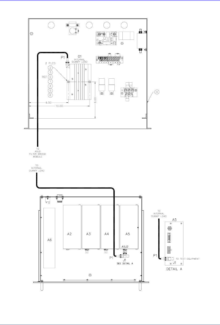
SOUTHERN AVIONICS COMPANY
SE125 Installation and Setup12-50 Optional Equipment
SAF83350 Rev A
Figure 12-10. Internal 50 Ohm Dummy Load

SOUTHERN AVIONICS COMPANY
SE125 Installation and Setup 12-51Optional Equipment
12.9.1 Parts list - SLF83350
SLF83350 Dummy load
REF
DES QTY PART NO. DESCRIPTION
1 1 SLE33350 INTERNAL DUMMY LOAD
2 2 20003016 SCREW; PHP 6-32X1/2 SS
3 2 22303000 WASHER; FLAT NO. 6 .312 OD X .030 NYLON
4 2 22003000 WASHER; FLAT NO. 6 SS
5 2 22013000 WASHER; SPLIT LOCK NO. 6 SS
P1 1 9C012050 CABLE ASSEMBLY; COAX RG58, TYPE N MALE/MALE
J1 156000030 CONNECTOR; BNC "T" FEMALE/MALE/FEMALE

SOUTHERN AVIONICS COMPANY
SE125 Installation and Setup12-52 Optional Equipment
This page intentionally left blank.