Southwire 14090T True RMS MultiMeter User Manual
Southwire Co. True RMS MultiMeter
UserManual.wiki
>
Southwire
>
14090T User Manual
user manual
Navigation menu
Upload a User Manual
Namespaces
Wiki Guide
HTML
PDF
Info
Views
User Manual
Discussion / Help
Navigation
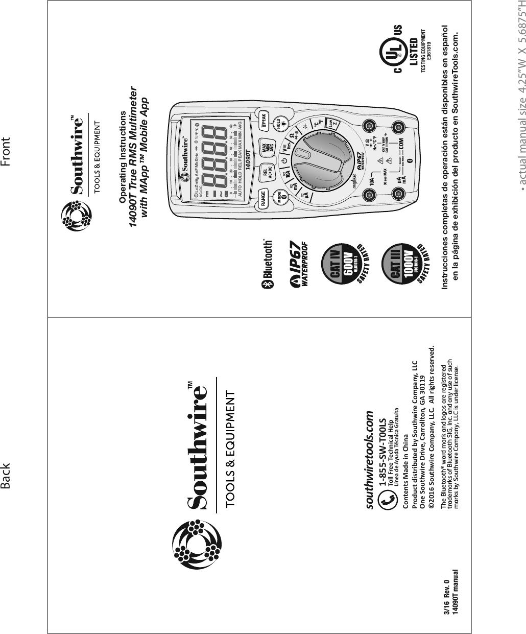
![Introduction1The Southwire 14090T wirelessly transmits data to the MApp™ mobile app via Bluetooth® technology allowing you to view, save, organize and share datalogs and take measurements from a safe distance. Visit nextgenmeters.southwiretools.com for mobile app download information. Functions include AC/DC voltage and current, resistance, continuity, capacitance, frequency, duty cycle, temperature, and diode test. True RMS readings provide accurate AC measurements and a Low Z setting eliminates false readings caused by “ghost” voltages. The 14090T also offers the added convenience of a built-in LED flashlight. This meter is fully tested and calibrated and, with proper use, will provide many years of reliable service. WARNINGS9LHK\UKLYZ[HUKHUKMVSSV^:HML[`9\SLZHUK6WLYH[PUN0UZ[Y\J[PVUZPU this manual before using this meter.;OLTL[LY»ZZHML[`MLH[\YLZTH`UV[WYV[LJ[[OL\ZLYPMUV[\ZLKPU HJJVYKHUJL^P[O[OLTHU\MHJ[\YLY»ZPUZ[Y\J[PVUZ,UZ\YL[OH[[OL[LZ[SLHKZHYLM\SS`ZLH[LKPU[OLPUW\[QHJRZHUKRLLW fingers away from the metal probe tips when taking measurements.)LMVYLJOHUNPUNM\UJ[PVUZ\ZPUN[OLZLSLJ[VYZ^P[JOHS^H`ZKPZJVUULJ[ the test leads from the circuit under test.<ZLVUS`<3SPZ[LK[LZ[SLHKZ^P[O[OLWYVWLYZHML[`JH[LNVY`YH[PUN*VTWS`^P[OHSSHWWSPJHISLZHML[`JVKLZ<ZLHWWYV]LKWLYZVUHS protective equipment when working near live electrical circuits - particularly with regard to arc-flash potential.<ZLJH\[PVUVUSP]LJPYJ\P[Z=VS[HNLZHIV]L=(*YTZ=(*WLHR or 60 V DC pose a shock hazard.+VUV[\ZLPM[OLTL[LYVY[LZ[SLHKZHWWLHYKHTHNLK=LYPM`VWLYH[PVUILMVYL\ZPUNTL[LYI`TLHZ\YPUNHRUV^USP]L]VS[HNLDo not use the meter in wet or damp environments or during electrical storms.+VUV[\ZL[OLTL[LYULHYL_WSVZP]L]HWVYZK\Z[VYNHZZLZDo not use the meter if it operates incorrectly. Protection may be compromised.+VUV[VWLYH[LTL[LY^OPSL3V^)H[[LY`^HYUPUNPZVU9LWSHJL batteries immediately. +VUV[HWWS`]VS[HNLVYJ\YYLU[[OH[L_JLLKZ[OLTL[LY»ZTH_PT\T rated input limits.When replacing the battery or fuses, be sure to secure the battery compartment door firmly to maintain the waterproof and dust proof integrity of the meter. Loose or overtightened screws, or an improperly seated o-ring may compromise the meter's water and dust ingress protection.](https://usermanual.wiki/Southwire/14090T/User-Guide-3012959-Page-2.png)