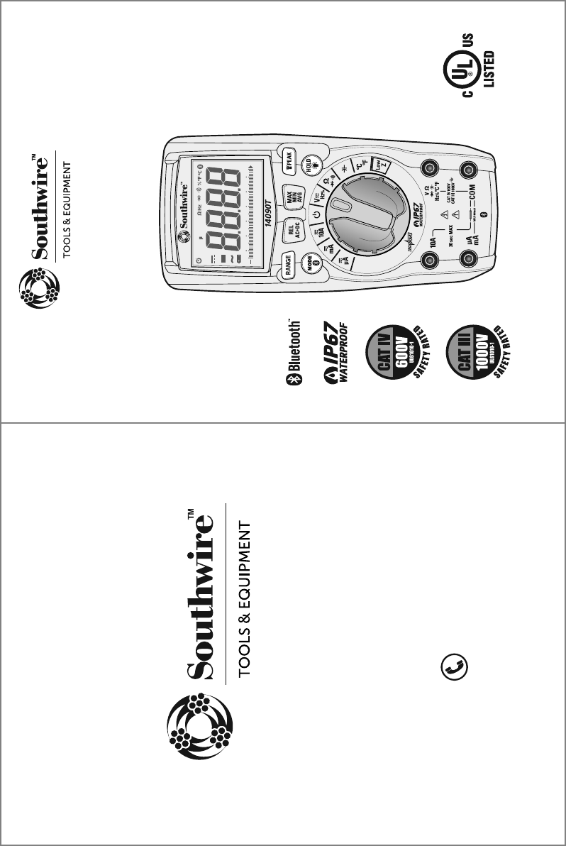
Southwire 14090T True RMS MultiMeter User Manual
Southwire Co. True RMS MultiMeter
user manual
0
10 20 30 40 50 60
LoZ mV AnF M k
AUTO HOLD REL PEAK MAX MIN AVG
AC+DC
• actual manual size 4.25”W X 5.6875”H
FrontBack
TESTING EQUIPMENT
E361819
3/16 Rev. 0
14090T manual
Contents Made in China
Product distributed by Southwire Company, LLC
One Southwire Drive, Carrollton, GA 30119
©2016 Southwire Company, LLC. All rights reserved.
southwiretools.com
1-855-SW-T00LS
Toll Free Technical Help
Línea de Ayuda Técnica Gratuita
Operating Instructions
14090T True RMS Multimeter
with MApp™ Mobile App
UL61010-1
The Bluetooth® word mark and logos are registered
trademarks of Bluetooth SIG, Inc. and any use of such
marks by Southwire Company, LLC is under license.
Instrucciones completas de operación están disponibles en español
en la página de exhibición del producto en SouthwireTools.com.

Introduction
1
The Southwire 14090T wirelessly transmits data to the MApp™ mobile app
via Bluetooth® technology allowing you to view, save, organize and share
datalogs and take measurements from a safe distance. Visit
nextgenmeters.southwiretools.com for mobile app download information.
Functions include AC/DC voltage and current, resistance, continuity,
capacitance, frequency, duty cycle, temperature, and diode test. True RMS
readings provide accurate AC measurements and a Low Z setting eliminates
false readings caused by “ghost” voltages. The 14090T also offers the
added convenience of a built-in LED flashlight. This meter is fully tested and
calibrated and, with proper use, will provide many years of reliable service.
WARNINGS
9LHK\UKLYZ[HUKHUKMVSSV^:HML[`9\SLZHUK6WLYH[PUN0UZ[Y\J[PVUZPU
this manual before using this meter.
;OLTL[LY»ZZHML[`MLH[\YLZTH`UV[WYV[LJ[[OL\ZLYPMUV[\ZLKPU
HJJVYKHUJL^P[O[OLTHU\MHJ[\YLY»ZPUZ[Y\J[PVUZ
,UZ\YL[OH[[OL[LZ[SLHKZHYLM\SS`ZLH[LKPU[OLPUW\[QHJRZHUKRLLW
fingers away from the metal probe tips when taking measurements.
)LMVYLJOHUNPUNM\UJ[PVUZ\ZPUN[OLZLSLJ[VYZ^P[JOHS^H`ZKPZJVUULJ[
the test leads from the circuit under test.
<ZLVUS`<3SPZ[LK[LZ[SLHKZ^P[O[OLWYVWLYZHML[`JH[LNVY`YH[PUN
*VTWS`^P[OHSSHWWSPJHISLZHML[`JVKLZ<ZLHWWYV]LKWLYZVUHS
protective equipment when working near live electrical circuits -
particularly with regard to arc-flash potential.
<ZLJH\[PVUVUSP]LJPYJ\P[Z=VS[HNLZHIV]L=(*YTZ=(*WLHR
or 60 V DC pose a shock hazard.
+VUV[\ZLPM[OLTL[LYVY[LZ[SLHKZHWWLHYKHTHNLK
=LYPM`VWLYH[PVUILMVYL\ZPUNTL[LYI`TLHZ\YPUNHRUV^USP]L]VS[HNL
Do not use the meter in wet or damp environments or during electrical storms.
+VUV[\ZL[OLTL[LYULHYL_WSVZP]L]HWVYZK\Z[VYNHZZLZ
Do not use the meter if it operates incorrectly. Protection may be compromised.
+VUV[VWLYH[LTL[LY^OPSL3V^)H[[LY`^HYUPUNPZVU9LWSHJL
batteries immediately.
+VUV[HWWS`]VS[HNLVYJ\YYLU[[OH[L_JLLKZ[OLTL[LY»ZTH_PT\T
rated input limits.
When replacing the battery or fuses, be sure to secure the battery compartment
door firmly to maintain the waterproof and dust proof integrity of the meter.
Loose or overtightened screws, or an improperly seated o-ring may
compromise the meter's water and dust ingress protection.
Input Limits
Function Maximum Input
Voltage AC or DC
Low Z
µA, mA Current AC/DC
10A Current AC or DC
Resistance, Continuity, Diode Test,
Capacitance,Frequency, Duty Cycle
Temperature
1000V AC RMS/1000V DC
600V AC RMS/600V DC
800mA 1000V fast acting fuse
10A 1000V fast acting fuse
(30 seconds max. every 15 minutes)
600V AC RMS/600V DC
600V AC RMS/600V DC
2
General Specifications
Insulation Class 2, Double insulation
Enclosure Double Molded, IP67 (waterproof and dust tight with plugs or
test leads inserted into input jacks)
Diode Test Test current 1.5mA max., open circuit voltage 3V typical
Continuity Test Audible signal if the resistance is approx. 50Ω or less
“ ” is displayed
Low Battery Indication
Display 6000 count LCD display
Over Range Indication “OL” is displayed
Polarity Minus symbol “-” is displayed for negative polarity
Measurement Rate 3 readings per second, nominal
Auto Power Off After approx. 15 minutes of inactivity
Input Impedance 10MΩ AC/DC Voltage
AC Response True RMS
Low Z Approx. 3kΩ input impedance
AC Bandwidth 50 to 1kHz
Batteries Four “AAA” 1.5V batteries
Fuses 800mA 1000V (6.3 x 32mm) fast blow/
10A 1000V (10 x 38mm) fast blow
Operating Environment 32°F to 104°F (0°C to 40°C) at < 70% relative humidity
Storage Environment -4°F to 140°F (-10°C to 60°C) at < 80% relative humidity
Operating Altitude 2000 meters maximum
Dimensions/ Weight 6.7” x 3.0” x 1.9”/0.85lb (170 x 75 x 48mm/386g)
Safety Complies with UL 61010-1 v.3 for measurement Category lV
600V and Category lll 1000V, Polution Degree 2
LIMITED WARRANTY AND LIMITATION OF LIABILITY ON
SOUTHWIRE METERS & TESTERS
Southwire Company, LLC warrants this product to be free from defects in
material and workmanship for two years from the date of purchase. This
warranty does not cover fuses, disposable batteries, or damage arising from
an accident, neglect, misapplication, contamination, modification, improper
maintenance or repair, operation outside of specifications, or abnormal
handling of the product.
Southwire’s sole liability, and the purchaser’s
exclusive remedy, for any breach of this warranty is expressly limited to
Southwire’s repair or replacement of the product. Whether Southwire repairs
or replaces the product will be a determination that Southwire makes at its
sole discretion.
SOUTHWIRE MAKES NO WARRANTY THAT THE PRODUCT WILL
BE MERCHANTABLE OR FIT FOR ANY PARTICULAR PURPOSE.
SOUTHWIRE MAKES NO OTHER WARRANTY, EXPRESSED OR
IMPLIED, OTHER THAN THE WARRANTY SPECIFICALLY SET FORTH
HEREIN.
SOUTHWIRE WILL NOT BE LIABLE FOR ANY INCIDENTAL,
CONSEQUENTIAL, INDIRECT, SPECIAL, OR PUNITIVE DAMAGES FOR
ANY BREACH OF THIS WARRANTY.
This warranty is void if this product is used for rental purposes. No product
reseller is authorized to extend any other warranty on Southwire’s behalf
relating to this product, and no such reseller warranty will be binding on
Southwire. If you have a warranty claim, or if the product needs to be
serviced during or after the warranty period set forth above, please contact
the Customer Service Department at 855-SWTOOLS (855-798-6657).
The sender is responsible for all shipping, freight, insurance, and packaging
costs associated with sending a product to Southwire. Southwire will not be
responsible for lost or damaged products returned pursuant to this warranty.
All products returned to Southwire under this warranty should be mailed to:
Southwire Company, LLC
Attention: Tool Warranty Return
840 Old Bremen Road
Carrollton, GA 30117
21
REGISTER YOUR PRODUCT
Register your product purchase at www.southwiretools.com. At Southwire,
we are dedicated to providing you with the best customer experience. By
following a few quick steps to register, you can experience quicker service,
more efficient support, and receive information on our future products. Simply
provide your model number, serial number, and just a few pieces of
information about yourself – it is that quick and easy.
20
Specifications cont.
60.00nF
600.0nF
6.000µF
60.00µF
600.0µF
6000µF
Input Protection: 600V AC RMS or 600V DC
Accuracy is not stated below 6nF
10pF
100pF
0.001µF
0.01µF
0.1µF
1µF
±(5.0% +35 digits)
±(3.0% +5 digits)
±(5.0% +5 digits)
Capacitance
Function Range Resolution Accuracy
± (% of reading + digits)
-4°F to 1400°F
-20°C to 760°C
Input Protection: 600V AC RMS or 600V DC
0.1°F
0.1°C
±(1.5% +9ºF)
±(1.5% +5ºC)
Temperature
Function Range Resolution Accuracy
± (% of reading + digits)
600.0Ω
6.000kΩ
60.00kΩ
600.0kΩ
6.000MΩ
60.00MΩ
Input Protection: 600V AC RMS or 600V DC
0.1Ω
1Ω
10Ω
100Ω
1kΩ
10kΩ
±(1.5% +5 digits)
±(2.0% +10 digits)
Resistance
Function Range Resolution Accuracy
± (% of reading + digits)
600.0µA
6000µA
60.00mA
600.0mA
10.00A
Overload Protection: µA, mA ranges: 800mA/1000V Fuse
10A range: 10A/1000V Fuse
0.1µA
1µA
10µA
0.1mA
10mA
±(1.0% +3 digits)
±(1.5% +3 digits)
DC Current
Function Range Resolution Accuracy
± (% of reading + digits)
3
Potential danger. Indicates the user must refer to the manual for important safety information
Indicates hazardous voltages may be present
Equipment is protected by double or reinforced insulation
Indicates the terminal(s) so marked must not be connected to a circuit where the
voltage with respect to earth ground exceeds the maximum safety rating of the meter
MAX
1000V
International Safety Symbols
Brief Description Typical Applications
Category Rating
Single phase receptacles
and connected loads
Three phase circuits and
single phase lighting
circuits in commercial
buildings
Connection point to
utility power and outdoor
conductors
- Household appliances, power tools
- Outlets more than 30ft (10m) from a CAT III source
- Outlets more than 60ft (20m) from a CAT IV source
- Equipment in fixed installations such as 3-phase
motors, switchgear and distribution panels
- Lighting circuits in commercial buildings
- Feeder lines in industrial plants
- Any device or branch circuit that is close to a CAT III source
- Primary distribution panels
- Overhead or underground lines to detached buildings
- Incoming service entrance from utility
- Outdoor pumps
CAT II
CAT III
CAT IV
The measurement category (CAT) rating and voltage rating is determined by a combination of the meter, test probes and any accessories connected to
the meter and test probes. The combination rating is the LOWEST of any individual component.
Safety Category Ratings
Insulated Tip On
Insulated Tip Removed
WARNING:
Operation is limited to
CAT II applications when the insulated tips
are removed from one or both test probes.
Refer to Input Limits section in this manual
for maximum voltage ratings.
NOTE: Meter is waterproof and dust tight
with supplied plugs or test leads inserted
into input jacks.
Test Leads
IP67 Rating
CAT IV 600V
CAT III 1000V
CAT II
1000V
4
FCC Statement
Warning: Changes or modifications to this unit not expressly approved by the Southwire Co. could void the user’s
authority to operate the equipment.
NOTE: This equipment has been tested and found to comply with the limits for a Class B digital device, pursuant to Part 15 of the
FCC Rules. These limits are designed to provide reasonable protection against harmful interference in a residential installation.
This equipment generates, uses and can radiate radio frequency energy and, if not installed and used in accordance with the
instructions, may cause harmful interference to radio communications.
However, there is no guarantee that interference will not occur in a particular installation.
If this equipment does cause harmful interference to radio or television reception, which can be determined by turning the
equipment off and on, the user is encouraged to try to correct the interference by one or more of the following measures:
• Reorient or relocate the receiving antenna.
• Increase the separation between the equipment and receiver.
• Connect the equipment into an outlet on a circuit different from that to which the receiver is connected.
• Consult the dealer or an experienced radio/TV technician for help.
The device must not be co-located or operating in conjunction with any other antenna or transmitter.
This device complies with Part 15 of the FCC Rules. Operation is subject to the following two conditions:
(1) this device may not cause harmful interference, and
(2) this device must accept any interference received, including interference that may cause undesired operation.
Complies with
IDA Standards
DA107392
19
Specifications cont.
600.0µA
6000µA
60.00mA
600.0mA
10.00A
All AC current ranges are specified from 5% to 100% of range.
Overload Protection: µA, mA ranges: 800mA/1000V Fuse
10A range: 10A/1000V Fuse
AC current bandwidth: 50 to 400Hz
0.1µA
1µA
10µA
0.1mA
10mA
±(1.0% +3 digits)
±(2.0% +8 digits)
AC Current
Function Range Resolution Accuracy
± (% of reading + digits)
9.999Hz
99.99Hz
999.9Hz
9.999kHz
Input Protection: 600V AC RMS or 600V DC
Sensitivity: >8V RMS
0.001Hz
0.01Hz
0.1Hz
1Hz
±(1.0% +5 digits)
Frequency
Function Range Resolution Accuracy
± (% of reading + digits)
6.000V
60.00V
600.0V
1000V
All AC + DC voltage ranges are specified from 5% to 100% of range.
Input Protection: 1000V AC RMS or 1000V DC
Input Impedance: 10M
AC voltage bandwidth: 50 to 400Hz
1mV
10mV
0.1V
1V
±(2.0% + 30 digits)
±(2.0% + 5 digits)
AC+DC Voltage
Function Range Resolution Accuracy
± (% of reading + digits)
20.0% to 80.0%
Input Protection: 600V AC RMS or 600V DC
Pulse Width: 0.1 to 100mS
Frequency Range: 5Hz to 10kHz
Sensitivity: >8V RMS
0.1% ±(1.2% +2 digits)
Duty Cycle
Function Range Resolution Accuracy
± (% of reading + digits)
FCC ID: 2AENI-14090T / IC: 20144-14090T
Maintenance
This Multimeter is designed to provide years of dependable service, if the following care
instructions are performed:
1. KEEP THE METER DRY. If it gets wet, wipe it off.
2. USE AND STORE THE METER IN NORMAL TEMPERATURES. Temperature extremes can
shorten the life of the electronic parts and distort or melt plastic parts.
3. HANDLE THE METER GENTLY AND CAREFULLY. Dropping it can damage the electronic
parts or the case.
4. KEEP THE METER CLEAN. Wipe the case occasionally with a damp cloth. DO NOT use
chemicals, cleaning solvents, or detergents.
5. USE ONLY FRESH BATTERIES OF THE RECOMMENDED SIZE AND TYPE. Remove old or
weak batteries so they do not leak and damage the unit.
6. IF THE METER IS TO BE STORED FOR A LONG PERIOD OF TIME, the batteries should
be removed to prevent damage to the unit.
IC Statement
This device complies with RSS247 of Industry Canada. This device complies with Industry Canada license-exempt RSS standard(s).
Operation is subject to the following two conditions: (1) this device may not cause interference, and (2) this device must accept any
interference, including interference that may cause undesired operation of the device.
Radiation Exposure Statement: This product complies with the Canadian portable RF exposure limit set
forth for an uncontrolled environment and is safe for its intended operation as described in this manual.
Further RF exposure reduction can be achieved if the product is kept as far as possible from the user’s body.
Déclaration de conformité d’Industrie Canada
Leprésent appareil est conforme aux CNR d'Industrie Canada applicable aux appareils radio Exempts de licence. L'exploitation est
autorisée aux deux conditions suivantes : (1) l'appareil ne doit pas produire de brouillage, et (2) l'utilisateur de l'appareil doit accepter
tout brouillage radioélectrique subi, meme si le brouillage est susceptible d'en compromettre le fonctionnement."
Déclaration d’exposition aux radiations : Ce produit est conforme aux limites d’exposition pour les appareils portables RF pour le
Canada établies pour un environnement non contrôlé. Le produit est sûr pour un fonctionnement comme décrit dans ce manuel. La
réduction aux expositions RF peut être augmentée si l’appareil peut être conservé aussi loin que possible du corps de l’utilisateur.
0
10 20 30 40 50 60
LoZ mV AnF M k
AUTO HOLD REL PEAK MAX MIN AVG
AC+DC
5
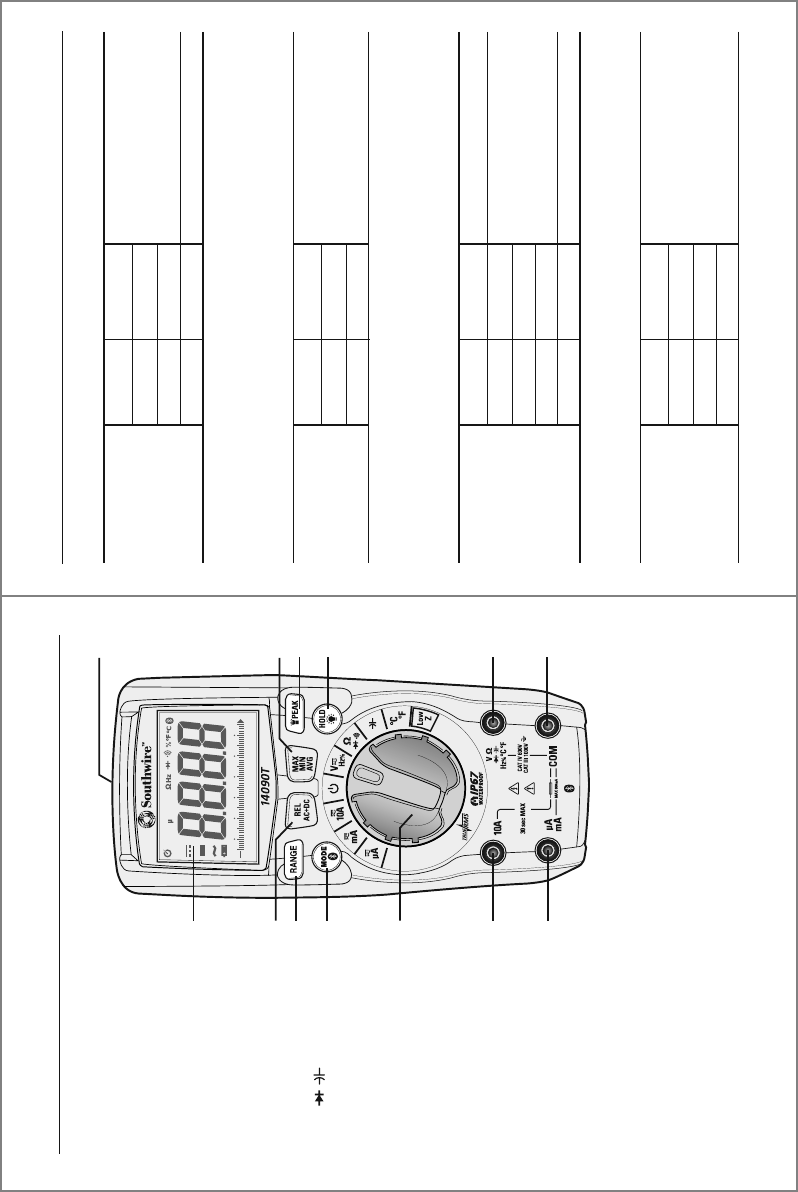
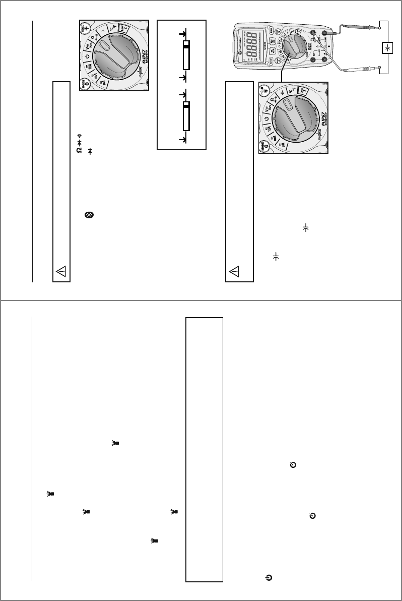
Meter Description
1.
2.
5.
6.
8.
9.
10.
12
13.
11.
7.
3.
4.
1. LCD display
2. REL/AC + DC button
3. RANGE button
4. MODE/Bluetooth® button
5. Rotary function switch
6. 10A input jack
7. µA, mA input jack
8. COM input jack
=£ / /Hz %/°C °F
input jack
10. HOLD/Backlight button
11. Flashlight/PEAK button
12. MAX/MIN/Average button
13. Flashlight
18
Specifications
6.000V
60.00V
600.0V
1000V
All AC voltage ranges are specified from 5% to 100% of range
Input Protection: 1000V AC RMS or 1000V DC
Input Impedance: 10MΩ
AC voltage bandwidth: 50 to 1kHz
1mV
10mV
0.1V
1V
±(1.0% +5 digits)
±(1.2% +5 digits)
AC Voltage
Function Range Resolution Accuracy
± (% of reading + digits)
600.0mV
6.000V
60.00V
600.0V
1000V
Input Protection: 1000V AC RMS or 1000V DC
Input Impedance: 10MΩ
0.1mV
1mV
10mV
0.1V
1V
±(0.9% + 8 digits)
±(0.9% + 5 digits)
±(1.0% + 3 digits)
DC Voltage
Function Range Resolution Accuracy
± (% of reading + digits)
600.0mV
6.000V
60.00V
600.0V
Input Protection: 600V AC RMS or 600V DC
Input Impedance: Approx. 3kΩ
0.1mV
1mV
10mV
0.1V
±(3.0% + 40 digits)
Low Z
DC Voltage
Function Range Resolution Accuracy
± (% of reading + digits)
Accuracy is stated at 65°F to 83°F (18°C to 28°C), less than 70% relative humidity
6.000V
60.00V
600.0V
All AC voltage ranges are specified from 5% to 100% of range
Input Protection: 600V AC RMS or 600V DC
Input Impedance: Approx. 3kΩ
AC voltage bandwidth: 50 to 1kHz
1mV
10mV
0.1V
±(3.0% +40 digits)
Low Z
AC Voltage
Function Range Resolution Accuracy
± (% of reading + digits)
6
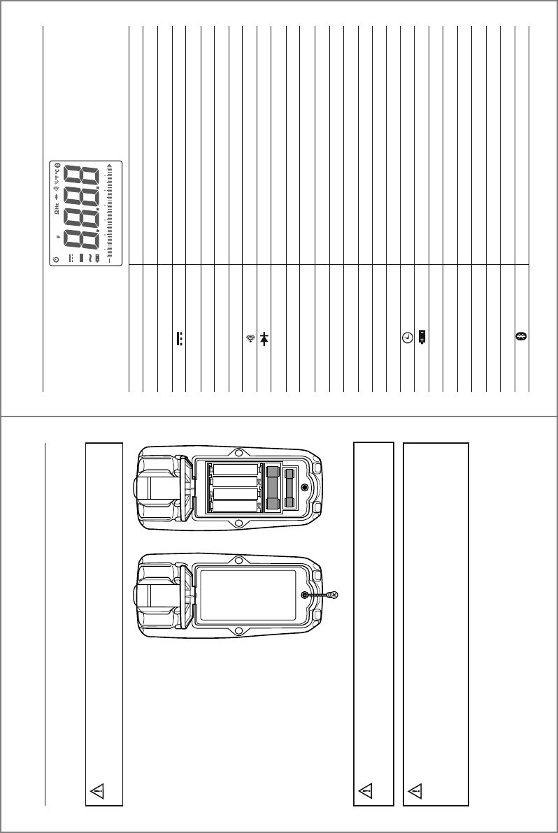
Symbols Used on LCD Display
V
A
~
-
Hz
%
£
F
°F
°C
n
µ
m
k
M
OL
AUTO
HOLD
LOZ
MAX/MIN/AVG
Peak
REL
Volts
Amperes
Alternating current
Direct current
Minus sign
Hertz (frequency)
Percent (duty cycle)
Ohms
Continuity
Diode test
Farads (capacitance)
Degrees Fahrenheit
Degrees Celsius
nano (10
-9
)
micro (10
-6
)
milli (10
-3
)
kilo (10
3
)
mega (10
6
)
Overload
Auto Power Off
Low battery
Autoranging
Display hold
Low Z (impedance)
Maximum/Minimum/Average
Peak hold
Relative
Bluetooth®
0
10 20 30 40 50 60
LoZ mV AnF M k
AUTO HOLD REL PEAK MAX MIN AVG
AC+DC
17
Operation cont.
To avoid electric shock, remove the test leads from
the meter before removing the battery/fuse cover.
WARNINGS:
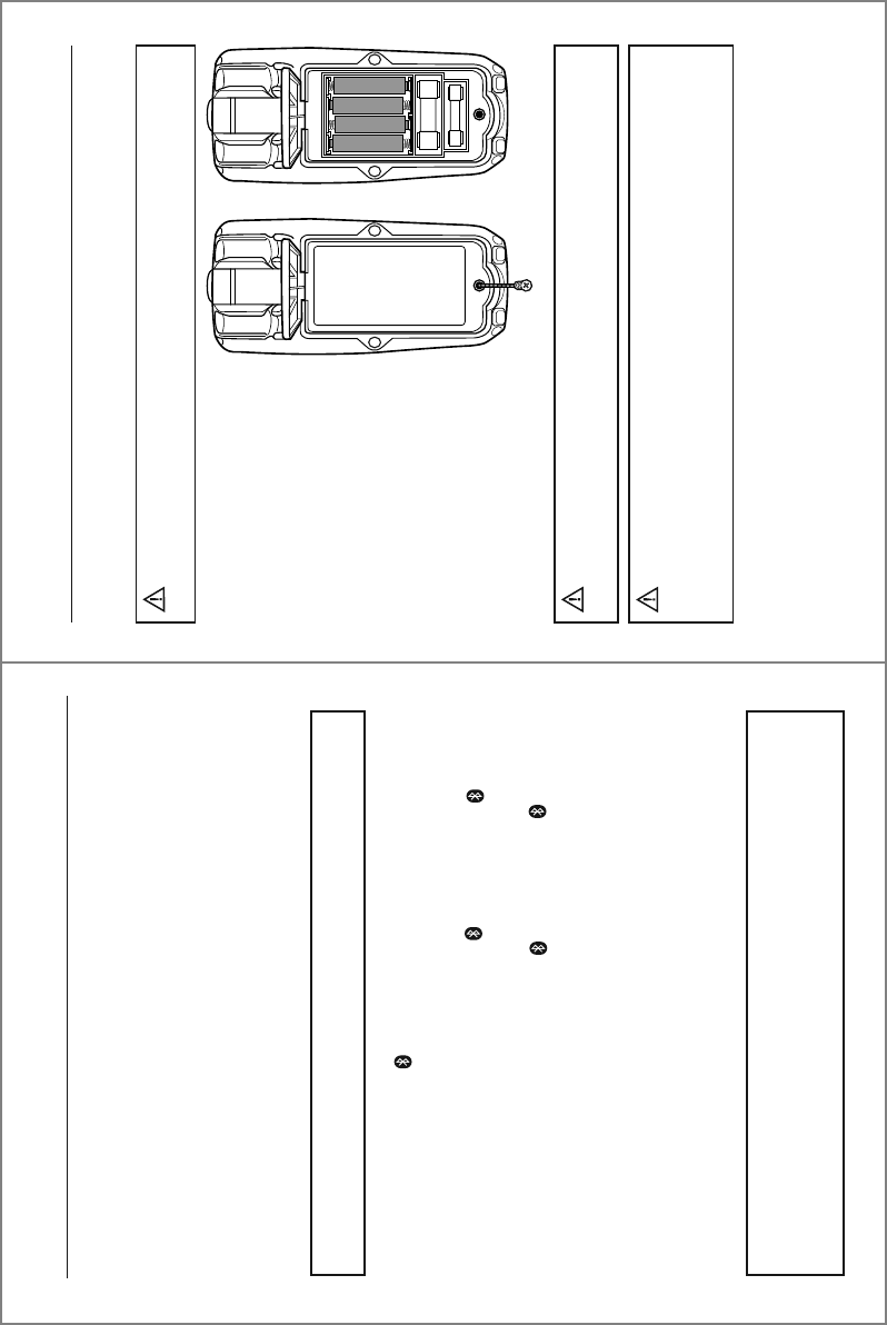
Fuse Replacement
To avoid electric shock, do not operate meter until
the battery/fuse cover is securely fastened to the meter.
WARNING:
1. Lift up the tilt stand.
2. Loosen the Phillips screw(s)
on the battery/fuse cover.
3. Remove the battery/fuse cover.
4. Gently remove fuse and install
new fuse into the holder.
5. Always use a UL recognized
fuse of the proper size and
value: 800mA/1000V (6.3 x
32mm) fast blow for the
µA/mA ranges and 10A/1000V
(10 x 38mm) fast blow for the
10A range.
6. Install the battery/fuse cover
and tighten the screw(s).
When replacing the battery or fuses, be sure to secure
the battery compartment door firmly to maintain the waterproof and dust
proof integrity of the meter. Loose or overtightened screws, or an improperly
seated o-ring may compromise the meter's water and dust ingress protection.
WARNING:
7
Operation
RANGE Button
The Autorange mode automatically selects the proper range for the measurement
being made and is generally the best mode for most applications. For measurement
situations requiring that a range be manually selected, perform the following:
1. Momentarily press the RANGE button. The “AUTO” indicator will no longer be
shown on the LCD display.
2. Momentarily press the RANGE button to step through the available ranges until
the desired range is selected.
3. To exit the Manual Ranging mode, press and hold the RANGE button until the
“AUTO” indicator reappears.
NOTE: The range button does not work on Frequency, Duty Cycle, Capacitance
or Temperature.
MODE/Bluetooth® Button
Momentarily press the MODE button to select AC or DC, Frequency or Duty Cycle,
Resistance, Continuity or Diode Test and °C or °F.
Bluetooth® technology allows readings to be displayed and stored on mobile devices.
To activate Bluetooth®, press and hold the MODE button until the “ ” symbol
appears on the LCD display. The Bluetooth® function should be disabled when not
connected to a mobile device in order to conserve battery power. To turn off the
Bluetooth® function, press and hold the MODE button until the “ ” symbol no
longer appears on the display.
Visit nextgenmeters.southwiretools.com for mobile app download information.
REL/AC + DC button
The RELATIVE function zeros out the reading on the display and stores it as a
reference. Subsequent readings will be displayed as the relative difference between
the actual measurement and the stored reference value. To activate, momentarily
press the REL/AC + DC button. The “REL” indicator will appear on the LCD display
along with the relative reading. Momentarily press the REL/HZ button again to
return to normal operation.
NOTE: The meter does not Autorange when the Relative mode is active. The
display will read OL if the difference exceeds the range. When this occurs, exit
REL and use the RANGE button to select a higher range. REL does not work
on Frequency, Duty Cycle, Continuity, Diode Test or Temperature.
16
Operation cont.
To avoid electric shock, do not operate the meter
until the battery/fuse cover is securely fastened to the meter.
WARNING:
To avoid electric shock, remove the test leads from
the meter before removing the battery/fuse cover.
WARNINGS:
Battery Replacement
1. Lift up the tilt stand.
2. Loosen the Phillips
screw(s) on the battery/fuse
cover.
3. Remove the battery/fuse cover.
4. Replace the batteries with four
AAA batteries.
5. Observe polarity as shown
inside battery compartment.
6. Install the battery/fuse cover
and tighten the screw(s).
When replacing the battery or fuses, be sure to secure
the battery compartment door firmly to maintain the waterproof and dust
proof integrity of the meter. Loose or overtightened screws, or an improperly
seated o-ring may compromise the meter's water and dust ingress protection.
WARNING:
0
10 20 30 40 50 60
LoZ mV AnF M k
AUTO HOLD REL PEAK MAX MIN AVG
AC+DC
8
Operation cont.
REL/AC + DC button cont.
The AC + DC function measures both the AC and DC components to derive the effective
RMS (AC + DC) value. The AC + DC mode is typically used when measuring voltage on
unfiltered rectifier circuits. To activate, press and hold the REL/AC + DC button until
“AC + DC” appears on the LCD display. Press and hold the REL/AC + DC button to
exit AC + DC. The meter will return to AC voltage.
MAX/MIN/AVG Button
1. Momentarily press the MAX/MIN/AVG button to activate the MAX/MIN/Average
mode. “MAX” will appear on the LCD display and the meter will display and hold
the highest reading. The meter will update the reading when a higher “max” occurs.
2. Momentarily press the MAX/MIN/AVG button again to view the lowest reading. “MIN”
will appear on the LCD display and the meter will display and hold the lowest
reading. The meter will update the reading when a lower “min” occurs.
3. Momentarily press the MAX/MIN/AVG button once more to view the average reading.
“AVG” will appear on the LCD display and the meter will display the running average.
The meter will update the reading when the average value changes.
4. Press and hold the MAX/MIN/AVG button to end MAX/MIN/Average and return to
normal operation.
NOTE: AC + DC can only be accessed when the rotary function switch is set to voltage.
NOTE: The meter does not Autorange when the MAX/MIN/AVG mode is active. The
display will read OL if the range is exceeded. When this occurs, exit MAX/MIN/AVG
and use the RANGE button to select a higher range. MAX/MIN/AVG does not work
on Frequency, Duty Cycle or Capacitance.
HOLD/Blacklight Button
To freeze the reading on the LCD display, momentarily press the HOLD button.
The “HOLD” indicator will be displayed while the reading is being held. Momentarily
press the HOLD button again to exit HOLD and return to normal operation.
To turn the backlight on, press and hold the HOLD button until the backlight turns on.
To turn the backlight off, press and hold the HOLD button until the backlight turns off.
15
Operation cont.
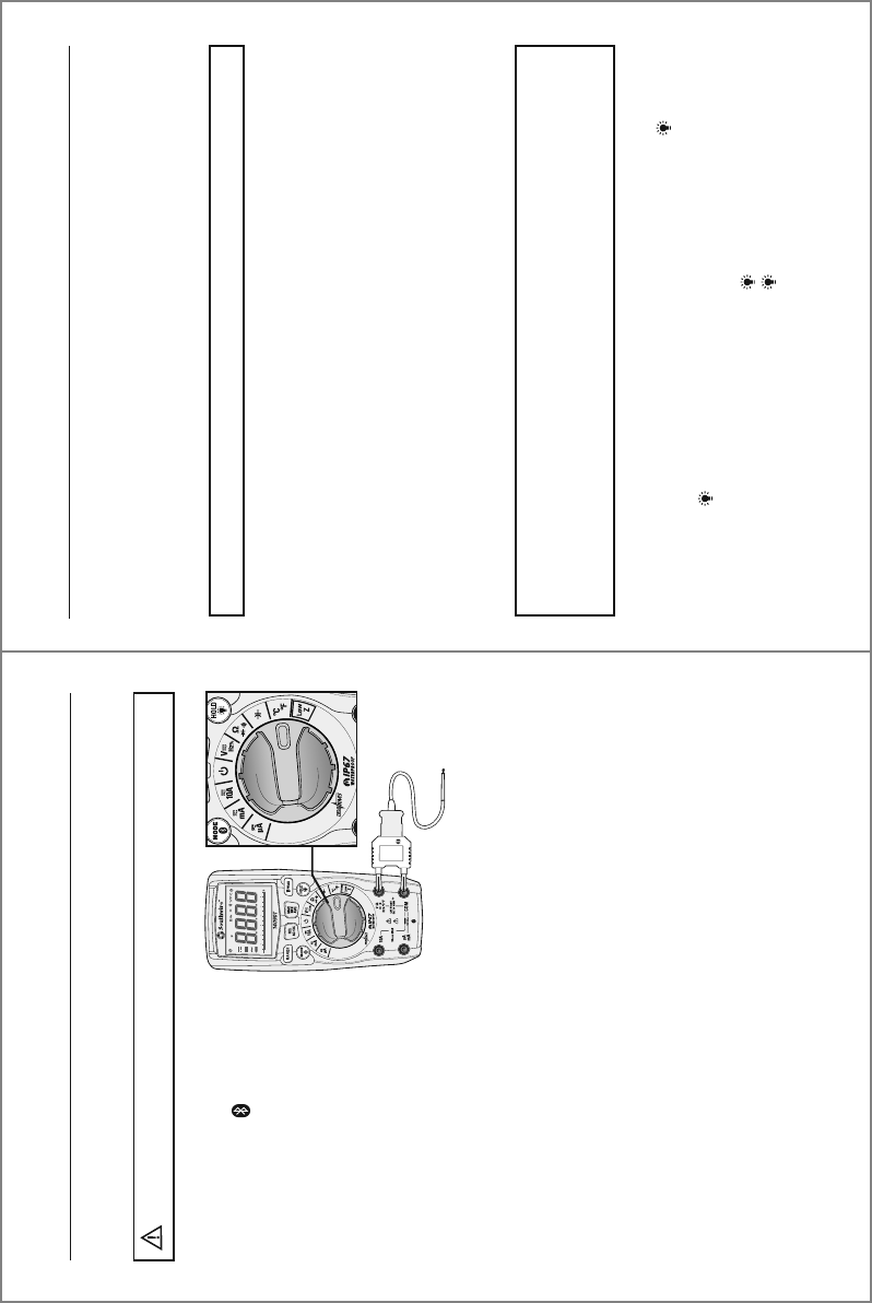
Temperature Measurements
1. Set the rotary function switch to
the °F °C position.
2. Press the MODE button to
select readings in °F or °C.
3. Connect the Temperature Probe
to the Banana Plug Adapter.
Note the – and + markings on
the adapter. Connect the adapter
to the meter, making sure the –
side goes into the COM input
jack and the + side goes into
the °C°F input jack.
4. Touch the tip of the Temperature
Probe to the object being measured.
Keep the probe touching the object
until the reading stabilizes (about
30 sec).
5. Read the temperature on the LCD display.
Do not touch the temperature probe to live circuits.
WARNINGS:
0
10 20 30 40 50 60
LoZ mV AnF M k
AUTO HOLD REL PEAK MAX MIN AVG
AC+DC
14
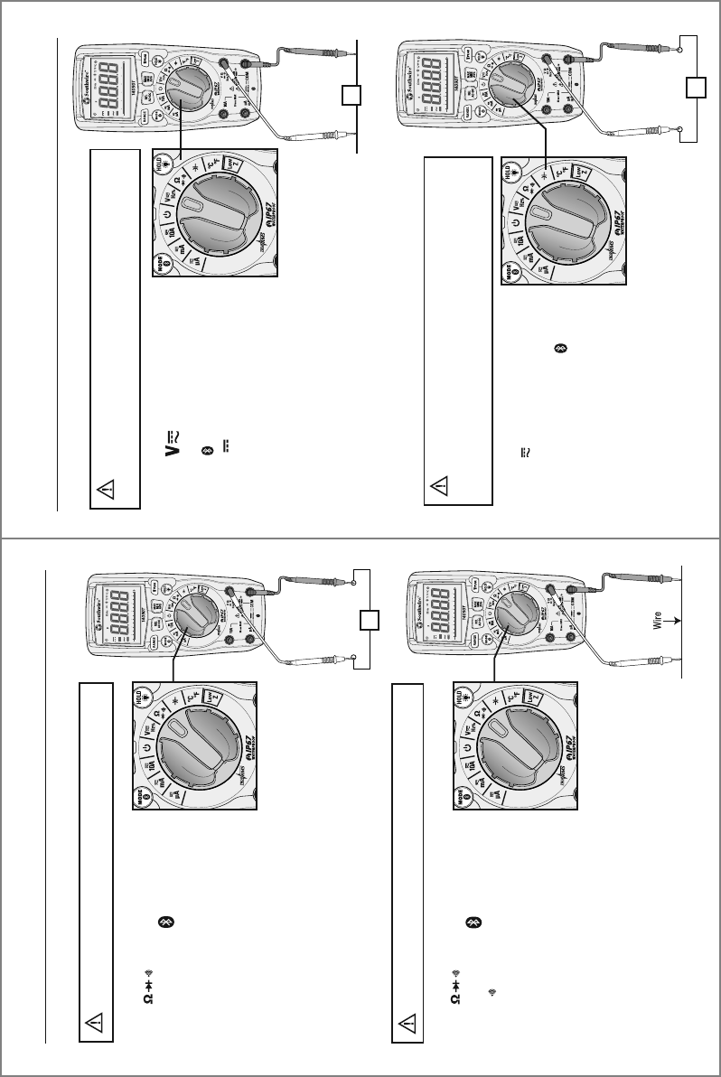
Operation cont.
1. Set the rotary function switch to
the position
2. Insert the black test lead into the
COM input jack and the red test
lead into the input jack.
3. Touch the test lead probes to
the capacitor under test.
4. Read the capacitance value on the
LCD display. It may take up to a
minute to get a stable reading on
large capacitors.
Capacitance Measurements
Safely discharge capacitors before
taking capacitance measurements.
WARNING:
1. Set the rotary function switch to the position.
2. Press the MODE button until the “ “ symbol
appears on the LCD display.
3. Insert the black test lead into the COM input jack and
the red test lead into the Ω input jack.
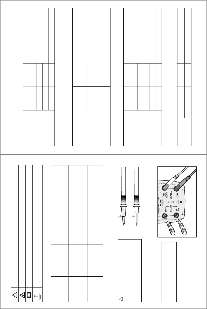
4. Touch the test lead probes to the diode under test.
5. Forward voltage will indicate
0.4 to 0.7 on the display. Reverse
voltage will indicate “OL”. Shorted
devices will indicate near 0 and
an open device will indicate “OL”
in both polarities.
Diode Test
Never test diodes in a live circuit.
WARNING:
Red Black Black Red
Probe Probe Probe Probe
Forward test Reverse test
9
Operation
NOTE: The meter does not Autorange when the PEAK mode is active. The
display will read OL if the reading exceeds the range. When this occurs, exit
PEAK and use the RANGE button to select a higher range.
Flashlight/PEAK Button
Momentarily press and the PEAK button to turn the flashlight on and off.
The PEAK function is accessible when measuring AC Voltage or Current. It captures and
displays the highest positive peak and the highest negative peak of the AC waveform.
1. Press and hold the PEAK button until “Peak MAX” appears on the LCD display.
The meter will display the highest reading and will update the reading when
a higher positive peak occurs.
2. To view highest negative peak, press the PEAK button for approximately one
second. “Peak MIN” will appear on the LCD display and the meter will display
and hold the highest reading. The meter will update the reading when a higher
negative peak occurs.
3. Press the PEAK button for approximately one second to switch between Peak
MAX and Peak MIN readings.
4. Press and hold the PEAK button to exit PEAK and return to normal operation.
Auto Power Off
To conserve battery power, the meter automatically turns off after approximately
15 minutes. To disable Auto Power Off, set the rotary function switch to the Off
position. Press and hold the MODE button while setting the rotary
function switch to the desired function.
Release the MODE button when the symbol no longer appears on the LCD display.
Auto Power Off can be restored by turning the meter off. As soon as the meter is
turned back on, the symbol will reappear indicating Auto Power Off is active.
0
10 20 30 40 50 60
LoZ mV AnF M k
AUTO HOLD REL PEAK MAX MIN AVG
AC+DC
0
10 20 30 40 50 60
LoZ mV AnF M k
AUTO HOLD REL PEAK MAX MIN AVG
AC+DC
0
10 20 30 40 50 60
LoZ mV AnF M k
AUTO HOLD REL PEAK MAX MIN AVG
AC+DC
0
10 20 30 40 50 60
LoZ mV AnF M k
AUTO HOLD REL PEAK MAX MIN AVG
AC+DC
10
Operation cont.
1. Set the rotary function switch to
the V HZ % position.
2. To select Frequency or % Duty
Cycle, press the MODE button
until the “Hz” or “%” symbol
appears on the LCD display.
3. Insert the black test lead into
the COM input jack and the red
test lead into the V input jack.
4. Touch the test lead probes to the circuit under test.
5. Read the frequency or % duty cycle on the LCD display.
Frequency and % Duty Cycle Measurements
Observe all safety precautions
when working on live voltages. Do not measure
frequency or duty cycle on circuits that exceed 600V.
WARNING:
Hz
1. Set the rotary function switch
to the HZ% position.
2. To select AC or DC, press the
MODE button until the AC “~”
or DC “ ” symbol appears on
the LCD display.
3. Insert the black test lead into the
COM input jack and the red test
lead into the V input jack.
4. Touch the test lead probes to the circuit under test.
If measuring DC voltage, touch the red test lead to
the positive side of the circuit and the black test lead
to the negative side of the circuit.
5. Read the voltage on the LCD display.
AC/DC Voltage Measurements
V
-+
Observe all safety precautions
when working on live voltages.
WARNING:
13
Operation cont.
1. Set the rotary function switch to
the position.
2. Press the MODE button until
the “ ” symbol appears on the
LCD display.
3. Insert the black test lead into the
COM input jack and the red test
lead into the Ω input jack.
4. Touch the test lead probes to the
device or wire under test.
5. A beeper will sound if the resistance is approximately
50Ω or less and the resistance value will be shown
on the LCD display.
Continuity
Never test continuity on a live circuit.
WARNING:
Ω
1. Set the rotary function switch to
the position
2. Press the MODE button until the
“Ω” symbol appears on the LCD
display.
3. Insert the black test lead into the
COM input jack and the red test
lead into the Ω input jack.
4. Touch the test lead probes to the component
under test. If the component is installed in a circuit,
it is best to disconnect one side before testing to
eliminate interference with other devices.
5. Read the resistance in on the LCD display.
Resistance Measurements
Never test resistance on a live circuit.
WARNING:
0
10 20 30 40 50 60
LoZ mV AnF M k
AUTO HOLD REL PEAK MAX MIN AVG
AC+DC
0
10 20 30 40 50 60
LoZ mV AnF M k
AUTO HOLD REL PEAK MAX MIN AVG
AC+DC
11
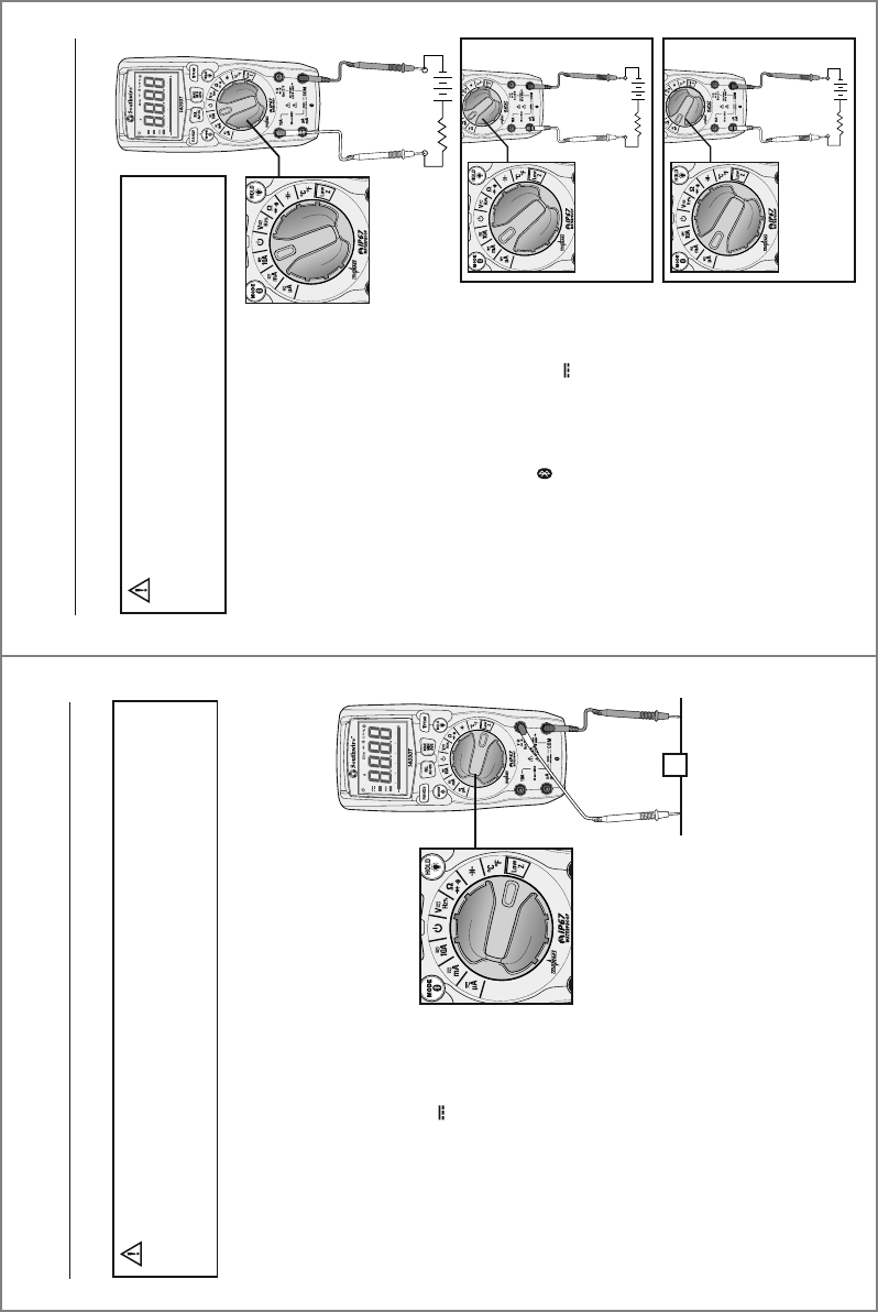
Operation cont.
1. Set the rotary function switch to
the Low Z position.
2. Press the MODE button to
select AC or DC voltage.
The AC “~” or DC “ ” symbol
will appear on the LCD display.
3. Insert the black test lead into
the COM input jack and the red
test lead into the V input jack.
4. Touch the test leads to the
circuit under test. If measuring
DC voltage, touch the red test
lead to the positive side of the
circuit and the black test lead
to the negative side of the circuit.
5. Read the voltage on the LCD display.
Low Z is used to check for “ghost” voltage. Ghost voltages are present when
non-powered wires are in close proximity to powered wires. Capacitive coupling
between wires make it appear that non-powered wires are connected to a real
source of voltage. The Low Z setting places a load on the circuit, which greatly
reduces the voltage reading when connected to ghost voltage.
Low Z AC/DC Voltage
Observe all safety precautions when working on live
voltages. Do not connect to circuits that exceed 600V when the meter is set
to Low Z. Do not use Low Z when testing circuits that could be harmed by
this function’s low input impedance.
WARNING:
V
-+
-+
-+
12
Operation cont.
1. Insert the black test lead into the
negative COM input jack.
2. For current measurements up to 10A,
set the rotary function switch to the
10A position and insert the red test
lead into the 10A input jack.
3. For current measurements up to
600mA, set the rotary function switch
to the mA position and insert the red
test lead into the µA mA input jack.
4. For current measurements up to 6000 µA,
set the rotary function switch to the µA
position and insert the red test lead into
the µA mA input jack.
5. Press the MODE button to select AC or
DC current. The AC “~” or DC “ ”
symbol will appear on the LCD display.
6. Remove power from the circuit under test,
then open up the circuit at the point where
you wish to measure current.
7. Touch the test lead probes in series with
the circuit being measured. For DC current,
touch the red probe to the positive side of
the circuit and touch the black probe to
the negative side of the circuit.
8. Apply power to the circuit.
9. Read the current on the LCD display.
AC/DC Current Measurements
MEASUREMENTS
UP TO 10A
Observe all safety precautions when
working on live circuits. Do not measure current on circuits
that exceed 1000V. Measurements in the 10A range should
be limited to 30 seconds maximum every 15 minutes.
WARNING:
MEASUREMENTS
UP TO 600mA
MEASUREMENTS
UP TO 6000 µA