Spacelabs Healthcare 670-1632-1400 96281-A09N, 96281-A09W, 96281-B09N, 96281-B09W, 96281-C09W User Manual 070 2407 02 Rev A
Spacelabs Healthcare, Inc. 96281-A09N, 96281-A09W, 96281-B09N, 96281-B09W, 96281-C09W 070 2407 02 Rev A
UserManual.wiki
>
Spacelabs Healthcare
>
670 1632 1400 User Manual
User Manual
Navigation menu
Upload a User Manual
Namespaces
Wiki Guide
HTML
PDF
Info
Views
User Manual
Discussion / Help
Navigation
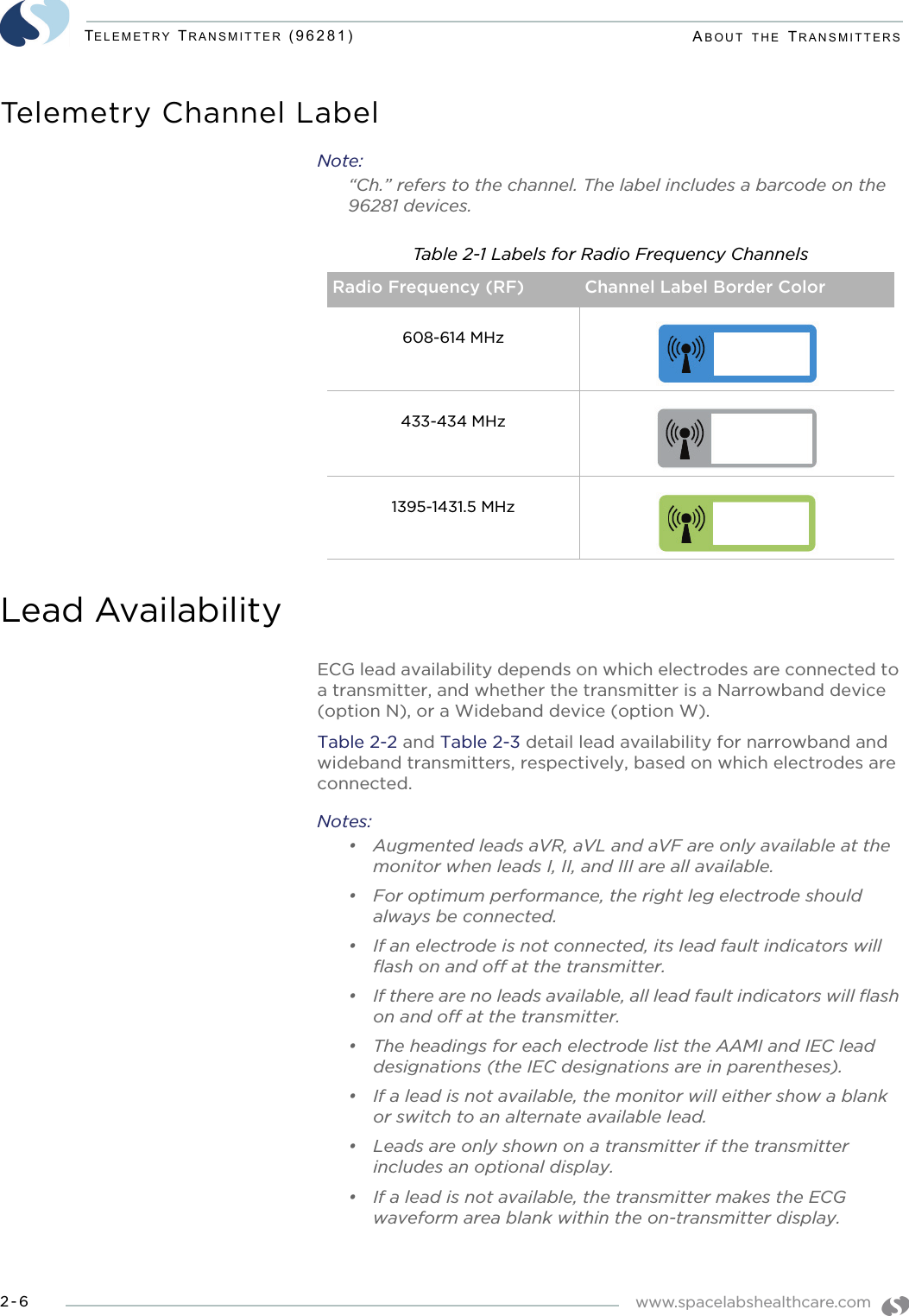
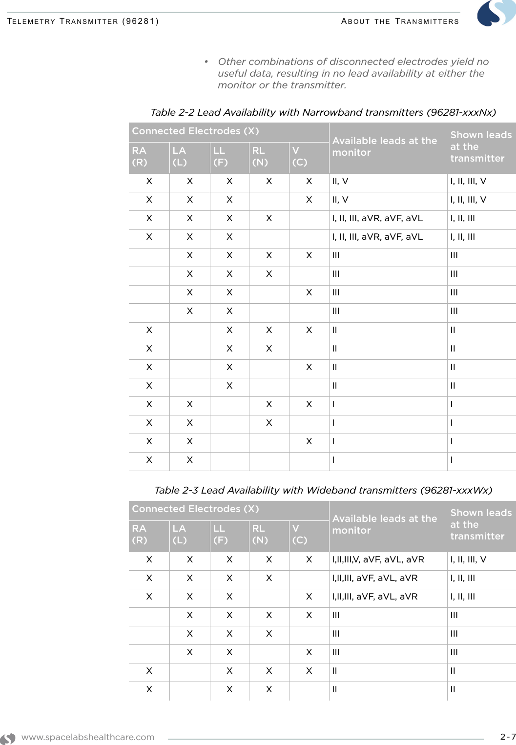
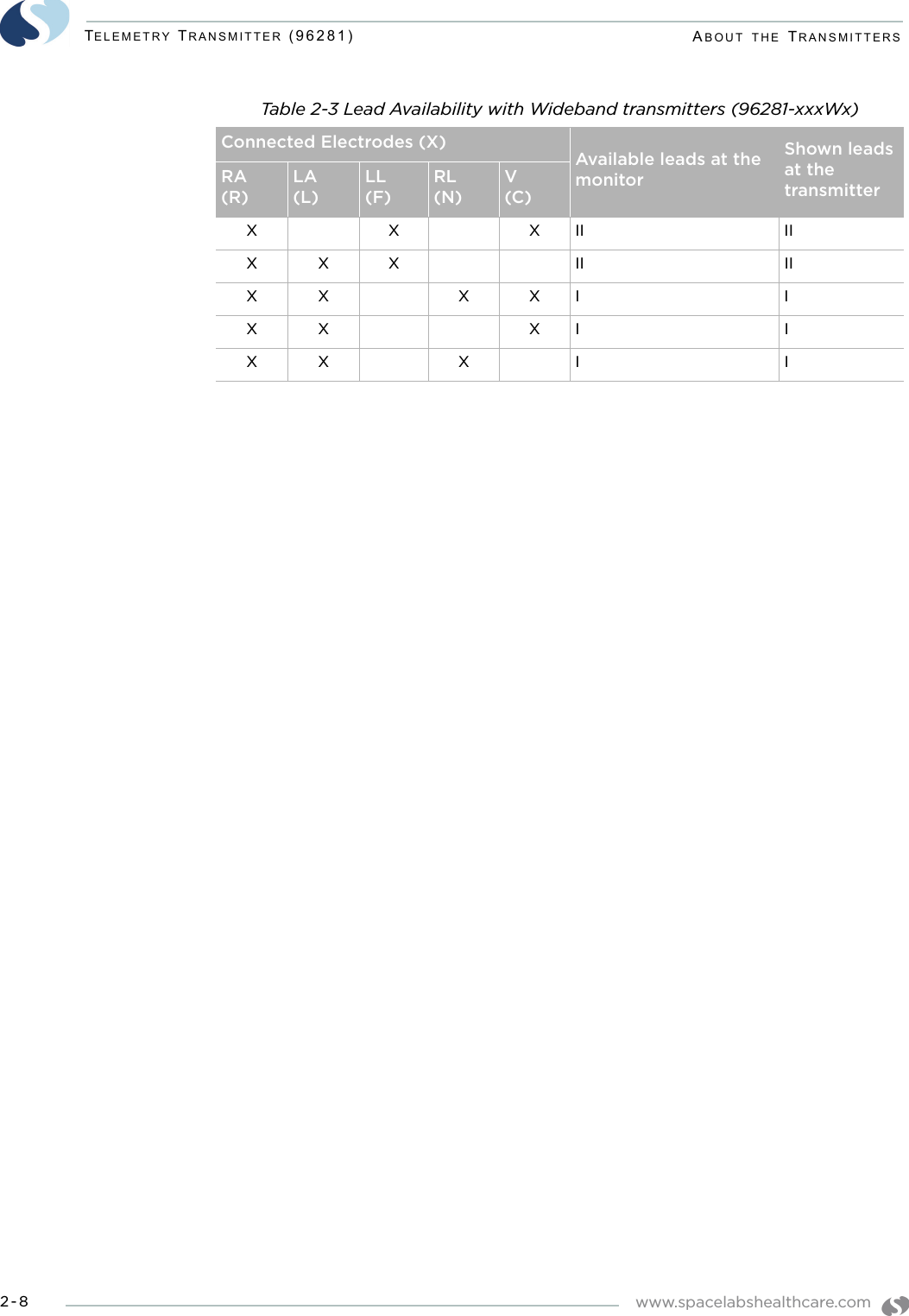
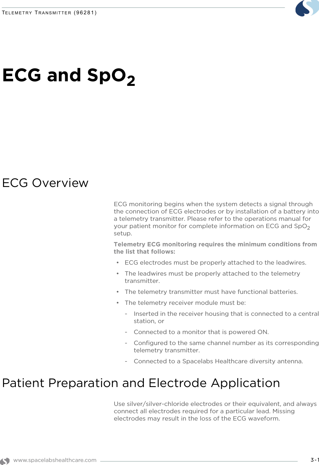
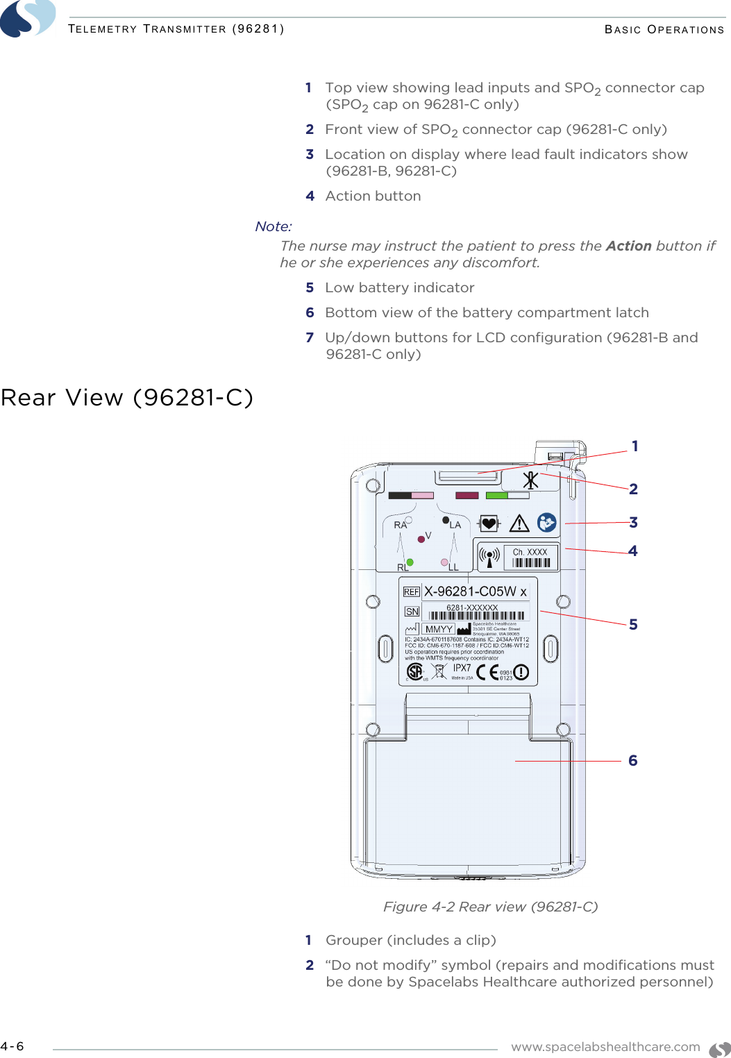
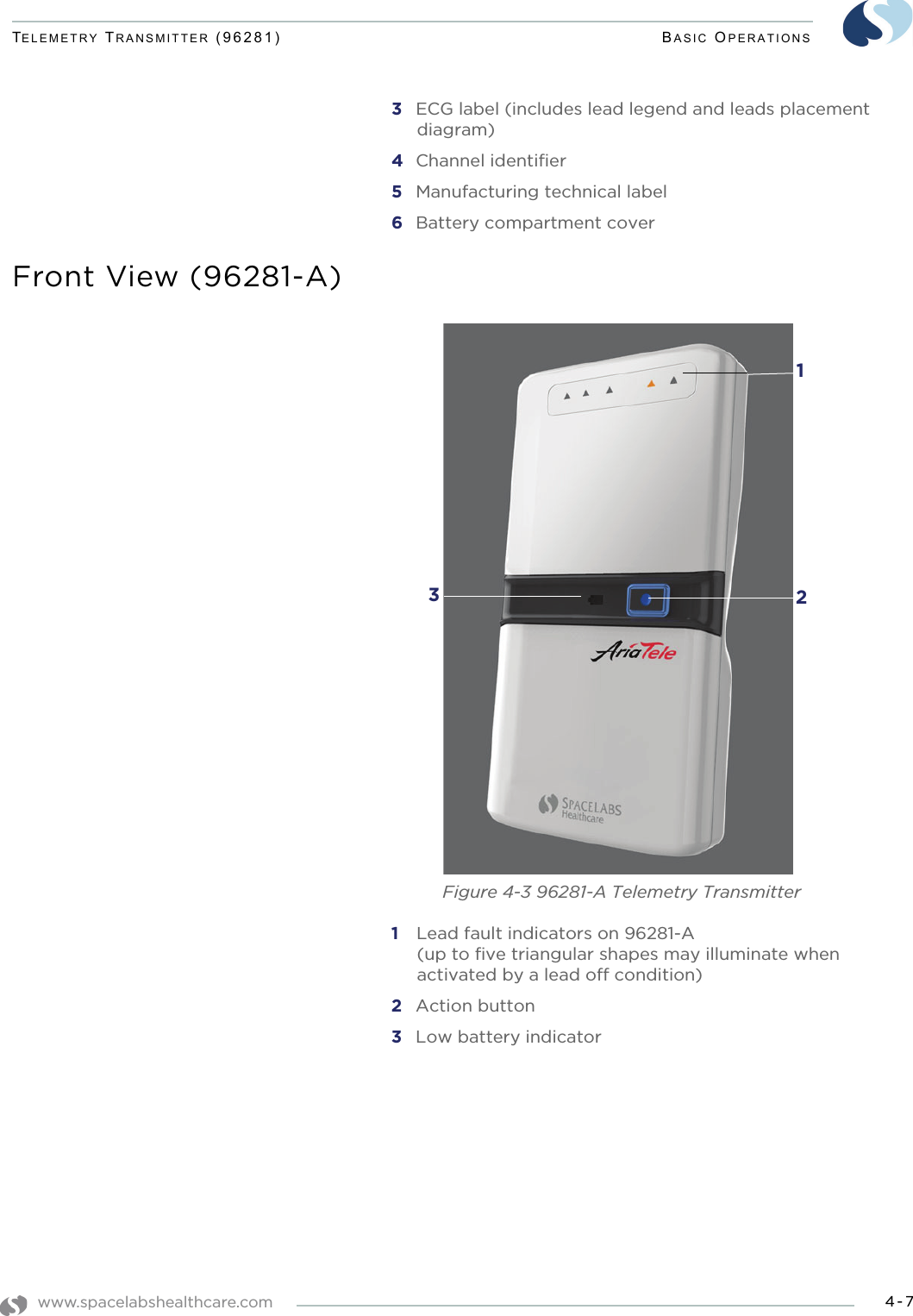
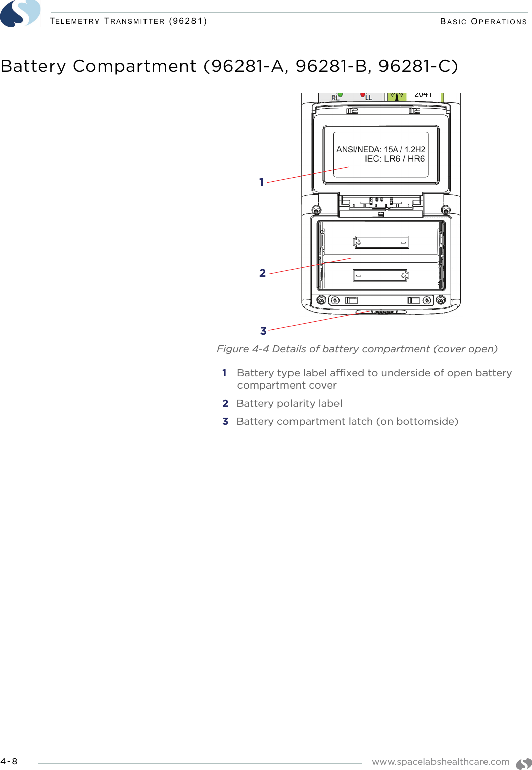
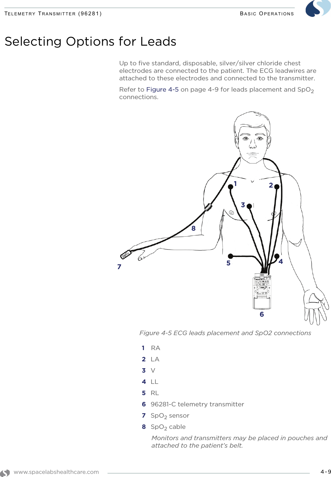
![www.spacelabshealthcare.com B-15TELEMETRY TRANSMITTER (96281) APPENDIX B — SYMBOLSPVC-Free (Polyvinyl Chloride)Do Not Reuse; Single Use OnlyReusableIPX1 Drip-ProofIPX7 Unit can withstand accidental immersion in one meter of water for up to 30 minutesReference Number or Order NumberUse by date [YYYY-MM-DD]RecycleNon SterileLatex-FreeDate of ManufactureManufacturerRadio transmitting device; elevated levels of non-ionizing radiationA CE mark certifies that a product has met EU health, safety, and environmental requirements, which ensure consumer safety. PVC2REF](https://usermanual.wiki/Spacelabs-Healthcare/670-1632-1400/User-Guide-2273476-Page-91.png)