Spacelabs Healthcare 670-1632-1400 96281-A09N, 96281-A09W, 96281-B09N, 96281-B09W, 96281-C09W User Manual 070 2407 02 Rev A
Spacelabs Healthcare, Inc. 96281-A09N, 96281-A09W, 96281-B09N, 96281-B09W, 96281-C09W 070 2407 02 Rev A
User Manual

070-2407-02 Rev. A | www.spacelabshealthcare.com November 2013
OPERATIONS MANUAL
Telemetry Transmitter
96281-A, 96281-B, 96281-C

TELEMETRY TRANSMITTER (96281)
OPERATIONS MANUAL
www.spacelabshealthcare.com
©2013 Spacelabs Healthcare
All rights reserved. Contents of this publication may not be reproduced in any form without
the written permission of Spacelabs Healthcare. Products of Spacelabs Healthcare are
covered by U.S. and foreign patents and/or pending patents. Printed in U.S.A. Specifications
and price change privileges are reserved.
Spacelabs Healthcare considers itself responsible for the effects on safety, reliability and
performance of the equipment only if:
• assembly operations, re-adjustments, modifications or repairs are carried out by persons
authorized by Spacelabs Healthcare, and
• the electrical installation of the relevant room complies with the requirements of the
standard in force, and
• the equipment is used in accordance with the operations manual.
Spacelabs Healthcare will make available, on request, such circuit diagrams, component part
lists, descriptions, calibration instructions or other information which will assist appropriately
qualified technical personnel to repair those parts of the equipment which are classified by
Spacelabs Healthcare as field repairable.
Spacelabs Healthcare is committed to providing comprehensive customer support beginning
with your initial inquiry through purchase, training, and service for the life of your Spacelabs
Healthcare equipment.
CORPORATE OFFICES
Corporate Headquarters
Spacelabs Healthcare
35301 SE Center Street
Snoqualmie, WA 98065
U.S.A.
Telephone: (1) 800-287-7108
Telephone: (1) 425-396-3300
Authorized EC Representative
Spacelabs Healthcare, Ltd.
43 Moray Place
Edinburgh, EH3 6BT
Scotland
Telephone: 44 (0) 131 240 6481
Fax: 44 (0) 131 240 6459
Please refer to http://www.spacelabshealthcare.com/en/company/trademarks for a full listing of
Spacelabs Healthcare trademarks. Other brands and product names used herein are trademarks of their
respective owners.
•Rx Only U.S. Federal law restricts the devices documented herein to sale by or on
the order of a physician.
• Before use, carefully read the instructions, including all warnings and cautions.

www.spacelabshealthcare.com I-I
Table of Contents
1Introduction
About This Manual ........................................................................................................... 1-1
Conventions Used in This Manual ....................................................................... 1-1
Overview of the Telemetry Transmitter
(96281-A/96281-B/96281-C)....................................................................................... 1-2
Manufacturer..................................................................................................................... 1-3
Relationship to Other Systems .................................................................................. 1-3
Intended Use .....................................................................................................................1-4
Indications for Use .......................................................................................................... 1-4
Warnings, Cautions, and Notes.................................................................................. 1-4
Potential Users .................................................................................................................1-8
Nurses .......................................................................................................................... 1-8
Monitor Technicians ................................................................................................ 1-9
Biomedical Engineers ............................................................................................. 1-9
Physicians ................................................................................................................... 1-9
Patients ....................................................................................................................... 1-9
Environmental Considerations ................................................................................... 1-9
Sources of Interference ........................................................................................ 1-10
Potential Sources of Damage ............................................................................. 1-10
Accessories...................................................................................................................... 1-10
Repairs............................................................................................................................... 1-10
2 About the Transmitters
Telemetry Transmitters (96281-A, 96281-B, 96281-C)...................................... 2-1
Lead Fault Indicators .................................................................................................... 2-2
Optional Leadwire Grouper ................................................................................. 2-3
Labeling.............................................................................................................................. 2-4
Leadwire Color Codes ........................................................................................... 2-4
AHA/AAMI Leadwire Labels ................................................................................. 2-5
IEC Leadwire Labels ................................................................................................. 2-5
Telemetry Channel Label ..................................................................................... 2-6
Lead Availability ............................................................................................................. 2-6
3ECG and SpO
2
ECG Overview .................................................................................................................. 3-1
Patient Preparation and Electrode Application .................................................. 3-1
To Set Up ECG Monitoring ......................................................................................... 3-2
To prepare the patient........................................................................................... 3-3
To apply ECG electrodes...................................................................................... 3-3
Adult Electrode Placement ................................................................................. 3-4
ECG Problem Solving ...................................................................................................3-4
Lead Fault Indication ............................................................................................. 3-5
Noise Detection ....................................................................................................... 3-5
False Alarms ............................................................................................................. 3-5
SpO2Overview................................................................................................................ 3-6
Traditional Pulse Oximetry .................................................................................. 3-6
Warnings and Cautions for SpO2 ..................................................................................................3-7
Electrodes, Leadwires, Sensors, and Sensor Cables .................................. 3-9
Electrodes, Leadwires, Sensors, and Sensor Cables ................................. 3-10
Setting Up SpO2 Monitoring ......................................................................................3-11
Ensuring Accurate SpO2 Monitoring ......................................................................3-11
SpO2 and Pulse Rate Specifications ......................................................................3-13
Displayed Range .......................................................................................................3-13
Resolution ...................................................................................................................3-13

TELEMETRY TRANSMITTER (96281)
www.spacelabshealthcare.com
I-II
Using the Sensorwatch Feature ............................................................................. 3-14
Enabling and Adjusting Alarms ...............................................................................3-15
Spacelabs Healthcare Technology .................................................................. 3-15
To enable and adjust SpO2 alarms (telemetry) ..........................................3-15
Additional Information for Telemetry Products ......................................... 3-15
Data Averaging ..............................................................................................................3-15
Telemetry ................................................................................................................. 3-15
Heart Rate Averaging .......................................................................................... 3-15
On-Transmitter Heart Rate Display Performance .......................................3-15
Display Details at the Host Monitor .......................................................................3-16
Printing SpO2 Waveforms .........................................................................................3-17
SpO2 Messages at the Host Monitor......................................................................3-18
SENSOR DISCONNECTED — Check connection at adapter cable .......3-19
SENSOR OFF PATIENT — Check connection at patient ..........................3-19
INSUFFICIENT SIGNAL — Reposition or replace sensor ..........................3-19
LOW SIGNAL STRENGTH — Reposition or replace sensor .....................3-19
AMBIENT LIGHT INTERFERENCE — Cover sensor area ......................... 3-20
NOISY SIGNAL ........................................................................................................ 3-20
FAULTY SENSOR — Replace sensor .............................................................. 3-20
HARDWARE INCOMPATIBILITY — Contact service ..................................3-21
Sensors ..............................................................................................................................3-21
Spacelabs Healthcare SpO2 Sensors .............................................................. 3-21
Additional Information ......................................................................................... 3-21
SpO2 Alarm Delays .......................................................................................................3-21
SpO2 Troubleshooting Guide ...................................................................................3-21
4 Basic Operations
Getting Started ................................................................................................................4-1
Transmitter Batteries ............................................................................................. 4-1
Host Monitors ........................................................................................................... 4-3
Telemetry Receiver Module ................................................................................ 4-4
Assigning a Telemetry Channel ......................................................................... 4-4
Basic Components .........................................................................................................4-5
Top, Front and Bottom View (96281-C) ......................................................... 4-5
Rear View (96281-C) .............................................................................................. 4-6
Front View (96281-A) ............................................................................................ 4-7
Battery Compartment (96281-A, 96281-B, 96281-C) ................................. 4-8
Selecting Options for Leads.......................................................................................4-9
Basic User Actions ....................................................................................................... 4-10
To send a recording to the central monitor or station .............................4-11
To unlock the user interface on the 96281 telemetry transmitter ........4-11
Basic Modes of Operation...........................................................................................4-11
View Mode .......................................................................................................................4-12
ECG ............................................................................................................................. 4-12
SpO2 ........................................................................................................................................................... 4-14
Status Messages at the Host Monitor................................................................... 4-15
Telemetry Transmitter with ECG Only Troubleshooting Guide ................. 4-16
Telemetry Transmitter with Display Troubleshooting Guide...................... 4-16
Telemetry Transmitter with Display and SpO2 Troubleshooting Guide..4-17
5 Cleaning, Disinfecting, and Sterilization
Cleaning Products Not Recommended for Use .................................................. 5-1
Cleaning the Display ...................................................................................................... 5-1
Transmitter, Leadwires, Cables, and Sensors...................................................... 5-2
Cleaning/Disinfecting ............................................................................................. 5-2
Recommended Cleaning Solutions ................................................................... 5-2
Accessories .................................................................................................................. 5-2

TELEMETRY TRANSMITTER (96281)
www.spacelabshealthcare.com I-III
Cleaning and Disinfecting the 96281Telemetry Transmitters and Cables5-3
Basic Cleaning and Low-level Disinfection .................................................... 5-3
Cleaning ECG Leadwires ...................................................................................... 5-4
Cleaning Buttons .................................................................................................... 5-4
Cleaning the Battery Cover ................................................................................. 5-4
A Appendix A — Guidance and Manufacturer’s Decla-
ration
Electromagnetic Environment ...................................................................................A-1
Electromagnetic Emmissions .....................................................................................A-1
Electromagnetic Immunity .........................................................................................A-2
Separation Distances ................................................................................................... A-4
Notes on ECG Leads .............................................................................................. A-5
B Appendix B — Symbols

TELEMETRY TRANSMITTER (96281)
www.spacelabshealthcare.com
I-IV

www.spacelabshealthcare.com 1-1
TELEMETRY TRANSMITTER (96281)
Introduction
Spacelabs Healthcare patient monitoring systems demonstrate an
ongoing commitment to innovation that supports decision-making
and enhances patient care.
Spacelabs Healthcare networking features support seamless data
acquisition and data exchange across the medical enterprise,
addressing the need for continuous information management. These
powerful tools help you care for patients more efficiently by
providing both local and remote access to patient data.
About This Manual
This manual provides instruction for specific features of the
Spacelabs Healthcare AriaTele™ Telemetry Transmitter (96281). It
does not address system issues such as antenna infrastructure,
receivers, central monitor or central station. Refer to the customer
documentation for your specific telemetry receiver for information
on antenna infrastructure. Refer to the customer documentation for
your central monitor for information on the central monitor or
station in use with the telemetry transmitter.
Conventions Used in This Manual
Some of the formatting conventions used in this manual are included
in the list that follows.
• For manuals viewed in PDF format, reference links are blue and
italicized. Blue italicized typeface is a link to additional
information in the manual. Hover the mouse over the blue text
and click to show the topic. Reference links are located
throughout the manual, including the Table of Contents.
• Non-blue italicized typeface are references to information
outside this manual. They may indicate references to other
manuals or information which is available in another form, as
www.spacelabshealthcare.com
1-2
TELEMETRY TRANSMITTER (96281) INTRODUCTION
identified by a title and/or a part number. Non-blue italicized
typeface may also refer to error or status messages that show on
the host monitor.
•Bold typeface indicates text labels, phrases, or titles that show
on an LCD or display which are part of a Spacelabs Healthcare
software application.
•Bold typeface may also indicate the formal name of graphical
user interface, such as an icon or control, but which does not
include a text label or title.
• Terms that are ALL CAPITALIZED may represent user interface
such as a key label or menu, or a status or error message on a
host monitor.
• Numbered steps are presented to accomplish a task. Some steps
may conclude in a step result—unnumbered, indented text. Step
results are shown in gray typeface. For an example of task steps,
click the cross-reference To send a recording to the central
monitor or station on page 4-11.
• Warnings, cautions, and notes are listed in the priority of the
information and formatted specifically as shown below.
Warnings are of the highest priority and notes are not as serious
as the warnings and cautions.
Notes:
Notes alert the user to relevant facts and conditions.
Overview of the Telemetry Transmitter
(96281-A/96281-B/96281-C)
When worn by a patient, the 96281 telemetry transmitter acquires
ECG data through electrodes attached directly to the patient’s body.
Additionally, the 96281-C telemetry transmitter can acquire SpO2
data through sensors attached to the patient’s body. It transmits
acquired data to the telemetry antenna infrastructure for processing
by a telemetry receiver. This transmitted data may then show on a
central station or bedside monitor. Refer to About the Transmitters
on page 2-1 for more detailed information about each telemetry
Warnings indicate potentially harmful conditions that may
lead to injury or death.
Cautions indicate conditions that may lead to damage to or
malfunction of the device.

www.spacelabshealthcare.com 1-3
TELEMETRY TRANSMITTER (96281) INTRODUCTION
transmitter model. The 96281 telemetry transmitter does not
indicate any alarm conditions. Alarms are configured, generated,
and activated within the receiver-side components of the Ultraview
System only.
Note:
SpO2 functionality is only available on the 96281-C telemetry
transmitter.
Manufacturer
The 96281 telemetry transmitter is manufactured by:
Relationship to Other Systems
The 96281 telemetry transmitter is related only to Spacelabs
Healthcare monitoring systems. Data collected by the transmitter
may be interfaced from the monitoring system to a hospital clinical
information system.
The telemetry transmitter is compatible with the list of receivers that
follow:
• Digital Telemetry System Receiver (90478) and Receiver
Housing (90479-A, 90479-B, 90479-C)
Refer to Bedside, Central, and Telemetry Systems CD-ROM and to
the Spacelabs Healthcare Service CD-ROM for information relating
to the 90478 and 90479 digital telemetry systems.
The 90478 receiver interacts with the Ultraview SL 91387-38 or
91387-39 central monitor, and with Ultraview SL patient monitors.
Note:
Not all products are available in all locales. Check with your local
Spacelabs Healthcare representative.
Spacelabs Healthcare
35301 SE Center Street
Snoqualmie, WA 98065
U.S.A.

www.spacelabshealthcare.com
1-4
TELEMETRY TRANSMITTER (96281) INTRODUCTION
Intended Use
The Spacelabs Healthcare AriaTele Telemetry Transmitter (96281),
when used in conjunction with a Spacelabs Healthcare Ultraview
patient monitor and telemetry receiver, provides a means for the
continuous monitoring of electrocardiographic signals in order to
detect abnormal cardiac rhythms, including life-threatening events
such as high and low heart rates, asystole, and ventricular fibrillation.
Optionally, on adult patients, additional abnormal cardiac rhythms,
such as ventricular runs, tachycardia, and ST-segment deviations are
detected.
The 96281 also provides a means for both continuous and episodic
monitoring of pulse blood oxygen saturation signals in order to
detect desaturation caused by abnormal pulmonary/circulatory
functions.
The 96281 is intended for use with either adult or neonatal patient
populations in a hospital environment.
Indications for Use
The 96281-A and 96281-B telemetry transmitters are indicated for
ECG monitoring of adult, pediatric, and neonatal patients. The
96281-C telemetry transmitter is indicated for ECG and SpO2
monitoring of adult, pediatric, and neonate patient populations.
Warnings, Cautions, and Notes
This chapter includes warnings, cautions, and notes specifically
related to digital telemetry. Refer to the ECG chapter in the Clinical
Parameters Operations Manual for warnings and cautions and
cautionary disclosures related to ECG. Refer to the product
specifications chapter for warnings and cautions and cautionary
disclosures that apply to electrodes and leadwires, defibrillators
(including automatic implantable cardiac defibrillators),
pacemakers, electrosurgical activity, several physiological
parameters, or to the monitoring system itself.
Obey these warnings and cautions to avoid injury or death to
individuals or damage to equipment.
• Review the device prior to each and every procedure. If it
shows signs of abuse then either make sure the device is
repaired in an appropriate manner, serviced, or retired
from use.

www.spacelabshealthcare.com 1-5
TELEMETRY TRANSMITTER (96281) INTRODUCTION
• Medical telemetry spectrum allocations may be assigned
to frequencies already allotted to other priority users.
Radio frequency interference from other products may
disrupt or impede telemetry patient monitoring during the
life of this equipment. You are urged to regularly consult
with applicable local and federal regulatory agencies
(e.g., FCC, FDA) regarding the locations and frequencies
of other spectrum users in your geographic area. A
Spacelabs Healthcare field service engineer may be able
to assist you in reconfiguring your equipment frequencies
to reduce the risk of interference. Spacelabs Healthcare
cannot, and does not, guarantee interference-free
telemetry operation.
• Telemetry systems may be more susceptible to
interference than hardwired systems; this may impact
signal quality.
• Do not use any transmitter that has been compromised by
liquid ingress. If fluid has collected in the battery
compartment, clean and dry it before use. If the
transmitter has been immersed in liquid, it must be
thoroughly dried before use. Not doing so may prevent
the transmitter from working properly. If the SpO2 sensor
has been immersed in liquid, it should be dried and
inspected for proper operation and replaced if necessary.
• The transmitters do not currently support inhibition of
their pacer detection functionality. Since Left Ventricular
Assist Devices (LVADs) can generate electromagnetic
noise having similar characteristics to pacemaker artifact,
users should pay particular attention to ECG traces
acquired using these transmitters when an LVAD is in use.
• Do not use the 96281 telemetry transmitter during
magnetic resonance imaging (MRI) procedures. MRI
operations will cause damage to the transmitter.
• Remove the 96281 telemetry transmitter from any patient
before beginning an MRI procedure.
• Operation of hand-held, wireless telephone equipment
(cordless telephones, cellular telephones) near telemetry
systems may cause interference and should be
discouraged. While personal communication devices are
turned on, a separation of >2 meters (>6.5 feet) should be
maintained between personal communication devices and
interior walls, the patient cables, and any electronic
medical device to which the patient may be connected.
Patients should not use any type of electronic
communication equipment while connected to any
electronic medical device without an on-site evaluation by
the biomedical staff. Two-way radio equipment and other
personal communication devices must be evaluated on
site to determine if additional space limitations are
needed.
www.spacelabshealthcare.com
1-6
TELEMETRY TRANSMITTER (96281) INTRODUCTION
Notes:
• Continuous monitoring of blood oxygen saturation values are
only supported in conjunction with ECG monitoring. SpO2
alarms are inhibited by ECG leads-off condition.
• Operation of this equipment may be subject to licensing
requirements by your local telecommunications authority.
Please check with your Spacelabs Healthcare field service
engineer.
• Spacelabs Healthcare’s telemetry equipment complies with
Part 95H of the FCC Rules and with RSS-210 of Industry
Canada and with requirements of other national spectrum
management authorities.
- Repeated here are operational cautions for biomedical
telemetry from the FCC Rules (47CFR15.242(f)):
“Biomedical telemetry devices must not cause harmful
• The Spacelabs Healthcare digital telemetry transmitters
are contra indicated for use with other medical
instrumentation (e.g., respiration monitors using
impedance pneumography, electrocautery) that source
electrical current through the patient. Further, telemetry
monitoring is contra indicated for the operating room
environment.
• The device should only ever be used for one patient at a
time.
• Opening the battery door and removing one or more of
the batteries will result in the patient NOT being
monitored and the ECG signal NOT being processed.
•SpO
2 alarms are inhibited by ECG lead-off conditions.
•This telemetry transmitter has a limited bandwidth range
of 0.05 to 40 Hz, which may adversely affect the
recording of high frequency components in the ECG
signal, especially when the morphology of the ECG
changes rapidly.
•This telemetry transmitter has a limited dynamic range of
+/- 4 mV, which may render the device vulnerable to
saturation by ECG signals with amplitudes higher than
4 mV.
•Clean the transmitter case with the battery door closed.
If fluid or other contaminants have collected in the battery
compartment, clean and dry it before use.
•Patients should not use any type of electronic equipment
(for example, portable radios, cellular telephones, pagers,
personal computers) while connected to any medical
electronic device without prior evaluation of that
electronic equipment by the biomedical engineering staff.

www.spacelabshealthcare.com 1-7
TELEMETRY TRANSMITTER (96281) INTRODUCTION
interference to licensed TV broadcast stations or to other
authorized radio services, such as operations on the
broadcast frequencies under subpart G and H of part 74 of
this chapter, land mobile stations operating under part
90 of this chapter in the 470-512 MHz band, and radio
astronomy operation in the 608-614 MHz band. (See
section 15.5). If harmful interference occurs, the
interference must either be corrected or the device must
immediately cease operation on the occupied frequency.
Further, the operator of the biomedical telemetry device
must accept whatever level of interference is received
from other radio operations. The operator, i.e., the health
care facility, is responsible for resolving any interference
that occurs subsequent to the installation of these
devices.”
- Installation of this telemetry device is permitted in
hospitals and health care facilities only. This device shall
not be operated in mobile vehicles (including ambulances
and other vehicles associated with health care facilities).
- The installer/user of a transmitter operating in the band of
608-614 MHz shall ensure that it is at least 80 km from the
Dominion Radio Astrophysical Observatory (DRAO) near
Penticton, British Columbia. The coordinates of DRAO are:
latitude N 49° 19’ 15”, longitude W 119°37’ 12”. For medical
telemetry systems not meeting this 80 km separation (e.g.
the Okanagan Valley, British Columbia) the installer/user
must coordinate with, and obtain written the concurrence
of, the Director of DRAO before the equipment can be
installed or operated. The Director of DRAO may be
contacted at 250-497-2300 (telephone) or 250-497-2355
(fax). (Alternatively, the Manager, Regulatory Standards,
Industry Canada, may be contacted.)
- Transmitters operating in the bands 1395-1400 MHz or
1429-1432 MHz shall not be operated in the areas of
Sydney, Nova Scotia, or Gander, Newfoundland and
Labrador. Please contact the local Industry Canada Office
for further information.
- Transmitters operating in the bands 608-614 MHz,
1395-1400 MHz or 1429-1432 MHz comply with Industry
Canada license-exempt RSS standard(s). Operation is
subject to the following two conditions: (1) this device may
not cause interference, and (2) this device must accept any
interference, including interference that may cause
undesired operation of the device.
• The user of this equipment is not authorized to make any
changes or alterations that could compromise the national
certifications.
• Operation of hand-held, wireless telephone equipment
(cordless telephones, cellular telephones) near telemetry
systems may cause interference and should be discouraged.
While personal communication devices are turned on, a
separation of >6.5 feet (>2 meters) should be maintained

www.spacelabshealthcare.com
1-8
TELEMETRY TRANSMITTER (96281) INTRODUCTION
between personal communication devices and interior walls,
the patient cables, and any electronic medical device to which
the patient may be connected. Patients should not use any
type of electronic communication equipment while connected
to any electronic medical device without an on-site evaluation
by the biomedical staff. Two-way radio equipment and other
personal communication devices must be evaluated on site to
determine if additional space limitations are needed.
• Telemetry equipment is authorized to operate license exempt
in the European Union’s (EU) Harmonized 433 to 434 MHz
Short Range Device (SRD) band. Telemetry equipment
operating in this band may not cause interference and must
accept interference from other devices found in the band.
Many countries outside the EU also permit access to this band
for qualifying devices.
• Operation of telemetry equipment in the 608 to 614 MHz
bands (part of the Wireless Medical Telemetry Service
(WMTS)) and in authorized spectrum of each country may be
geographically restricted by government regulation.
Operation of this equipment in all U.S. WMTS bands requires
coordination and registration with the FCC-designated
frequency coordinator.
• Operation of telemetry equipment in the 1395 to 1400 MHz
and 1429 to 1432 MHz bands (part of the Wireless Medical
Telemetry Service (WMTS)) and in authorized spectrum of
each country may be geographically restricted by government
regulation. Operation of this equipment in all U.S. WMTS
bands requires coordination and registration with the
FCC-designated frequency coordinator.
• Operation of this equipment may be subject to liscensing
requirements by your local telecommunications authority.
Check with your Spacelabs Healthcare field service engineer.
• Users of medical telemetry equipment are cautioned that the
operation of the equipment could result in harmful
interference to other nearby medical devices.
Potential Users
The potential users of the 96281 telemetry transmitter are classified
into the groups that follow.
Nurses
Nurses attach the transmitter to the patient, maintain the ECG
electrodes, SpO2 sensor, and generally care for the patient. They
may also admit the patient to the monitoring system and monitor
the patient.

www.spacelabshealthcare.com 1-9
TELEMETRY TRANSMITTER (96281) INTRODUCTION
Monitor Technicians
Monitor technicians may surveil patients at a central station or
monitoring room configuration. Technicians may also admit patients
to the system and prepare the transmitter with fresh batteries and
electrodes.
Biomedical Engineers
A biomedical engineer, or biomed, may install, support, and repair
monitoring systems, including telemetry. Biomeds may work directly
for the hospital, for a third-party contract organization, or be a
Spacelabs Healthcare Field Service Engineer (FSE).
Physicians
Physicians may be common reviewers of the physiological data that
is collected and subsequently presented on a monitor or at a full
disclosure review station. Physicians may be responsible to treat
telemetry patients, including the use of defibrillation.
Patients
A telemetry patient may carry a transmitter in a gown pocket or in a
pouch (the transmitter is connected to the patient by way of
electrodes attached directly to the patient’s body). The patient can
initiate a recording by pressing the Action button on the front of the
transmitter if it is configured for this at the central station or bedside
monitor.
Note:
The central monitor or station may be configured to ignore
messages from individual telemetry transmitter units if a patient
is likely to misuse this capability. Refer to the user manuals for
your central monitor or station for more information.
Environmental Considerations
The hospital environment where this product is used could contain
environmental conditions that may affect the product.
Since this is a wireless radio frequency (RF) device, outside
interference can come from multiple sources. Even while operating
within the WMTS band in North America, interference and
coexistence issues may occur with other products.
The device shall be sent to a separate collection facility for recovery
and recycling.
Refer to the data sheet for the AriaTele Transmitter (96281) for
operating and storage details.

www.spacelabshealthcare.com
1-10
TELEMETRY TRANSMITTER (96281) INTRODUCTION
Sources of Interference
Some potential sources of interference are included in the list that
follows:
• Monitoring patients in elevators during transport to other units,
or outside of the primary unit.
Poor transmission of signals may occur. Use a monitor with a
display if elevator transport is required.
• Monitoring patients off the ward (radiology areas, for example)
may result in poor reception due to antenna placement and wall
construction.
If monitoring is necessary, the augmentation of the antenna
system may be required.
• Defibrillation of a patient who is wearing the product.
• Implanted or external pacemakers associated with a patient who
is wearing the product.
Potential Sources of Damage
• The product accidentally drops onto hard surfaces, such as
flooring or walls, or into sinks or toilets.
• Exposure to disinfectant and various types of cleaner.
Refer to Cleaning, Disinfecting, and Sterilization on page 5-1 for
more detailed information.
Accessories
For optimum performance, only use the device with recommended
accessories. Refer to the data sheet AriaTele Transmitter (96281) for
transmitter accessories and to the Spacelabs Healthcare Supplies
and Accessories Catalog for a list of suitable electrodes and supplies
from Spacelabs Healthcare.
Repairs
Transmitters that are damaged and need repair should be sent to an
authorized Spacelabs Healthcare repair depot for repair, recovery,
or recycling. Check with your Spacelabs Healthcare representative
for locations.
www.spacelabshealthcare.com 2-1
TELEMETRY TRANSMITTER (96281)
About the Transmitters
Telemetry Transmitters (96281-A, 96281-B, 96281-C)
The telemetry transmitters function as part of a digital telemetry
system. This system consists of transmitters, diversity antennas,
receiver modules, and either a receiver housing and/or a monitor.
Typically a request comes from a central host monitor to obtain data
from electrodes and/or remote sensors attached to a patient which
are connected to the transmitter. The central or bedside monitor
tells a receiver what channel to begin listening on—one that matches
the transmitter on the patient.
Refer to the data sheet AriaTele Transmitter (96281) for the options
available with the 96281 telemetry transmitter. Contact your
Spacelabs Healthcare representative for the complete compatibility
list.
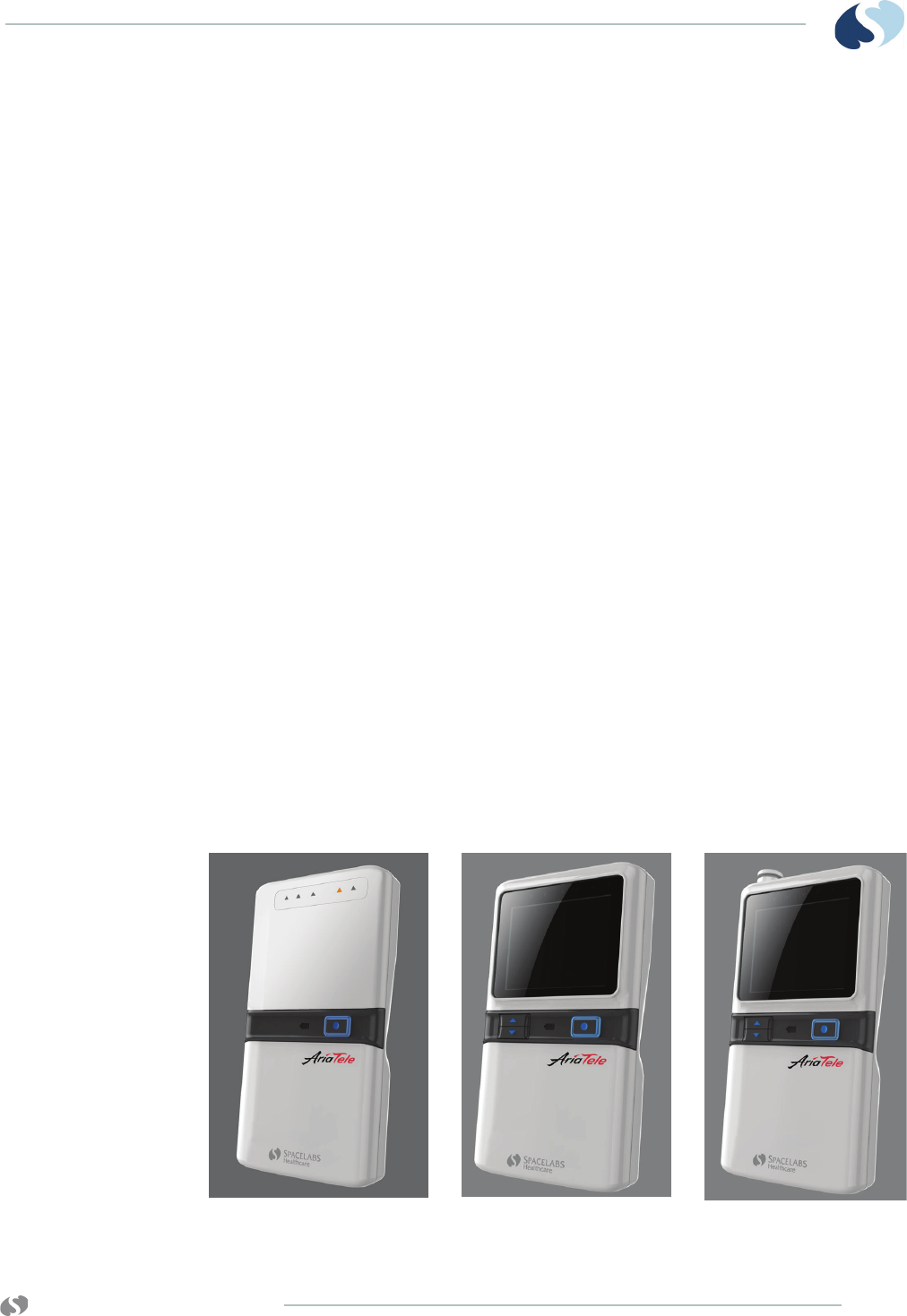
96281-A 96281-B 96281-C

www.spacelabshealthcare.com
2-2
TELEMETRY TRANSMITTER (96281) ABOUT THE TRANSMITTERS
The patient-worn transmitters are small battery-powered devices
that monitor ECG activity and SpO2 data (96281-C only) and
transmit this information to the telemetry receiver module.
Each transmitter only uses one channel. The wideband units transmit
four leads; the narrowband units transmit two leads. The
transmitters with a display show four leads.
A label is affixed to each transmitter with its channel number
representing a unique radio frequency. Telemetry receivers are
tuned from the Spacelabs Healthcare monitor touchscreen
to receive the available transmitter frequencies.
All transmitters are assigned a channel number at the factory. When
using telemetry, the receiver must be assigned the appropriate
channel for a patient at the bedside or central monitor. Admission of
the patient is done at the monitor.
Lead Fault Indicators
The 96281 transmitter has amber indicators on the front of the
transmitter case. Each indicator provides the status of its respective
leadwire and flashes if the leadwire is disconnected from the skin
electrode or if the skin electrode makes poor electrical contact with
the patient. It is possible for all lead fault indicators to flash
simultaneously if all electrodes are disconnected. In addition, all
indicators may flash if the transmitter is unable to determine an ECG
waveform.
Up to five standard, disposable, silver/silver chloride chest
electrodes may be connected to the patient. The ECG leadwires are
attached to these electrodes and connected to the transmitter.
The 96281 telemetry transmitter is designed to operate with five
patient leadwires. If you choose to use only three or four patient
leadwires, patient information is still processed, but a lead fault
message will show on the host monitor. An optional leadwire
grouper is available for use with the ECG leadwires (refer to Figure
2-2 on page 2-3).
www.spacelabshealthcare.com 2-3
TELEMETRY TRANSMITTER (96281) ABOUT THE TRANSMITTERS
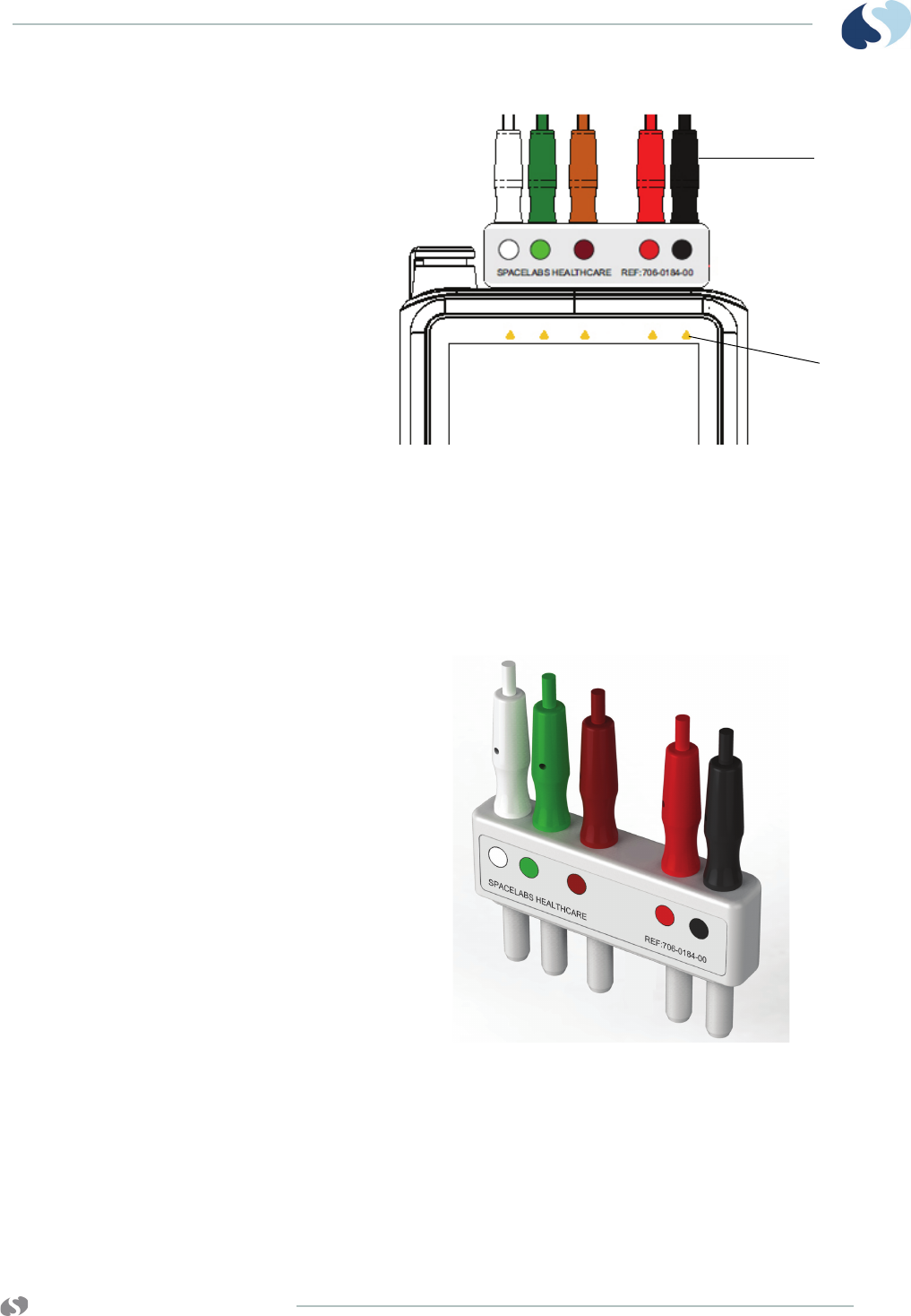
Figure 2-1 ECG leadwire connectors and
lead fault indicators (96281-C)
1 Leadwire connectors
2 Lead fault indicators
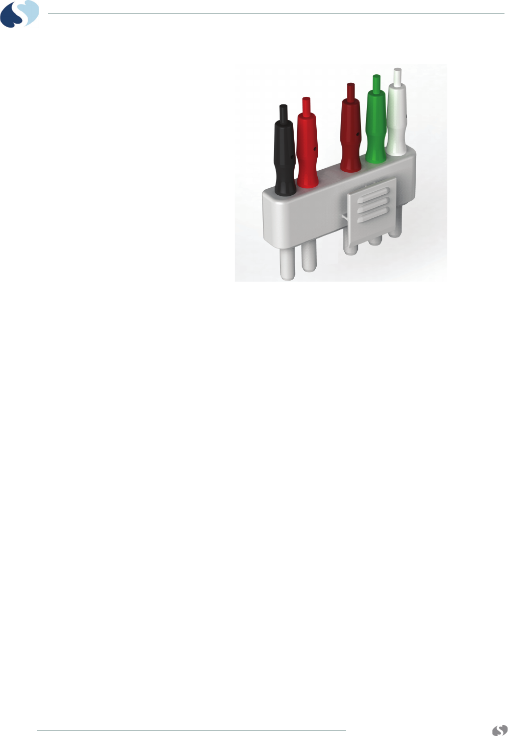
Optional Leadwire Grouper
Figure 2-2 Leadwire grouper
(front view including ECG connectors and color codes label)
1
2
www.spacelabshealthcare.com
2-4
TELEMETRY TRANSMITTER (96281) ABOUT THE TRANSMITTERS
Figure 2-3 Leadwire grouper
(rear view including clip and ECG connectors)
Labeling
Leadwire Color Codes
Both AHA/AAMI or IEC color codes are used on the leadwires and
the transmitter labeling. The color codes for your transmitter and
leadwires are based on the preference in your locale. These color
variations are shown on the back label of the transmitter, front of the
leadwire grouper, and on the individual ECG connectors and
leadwires. This is to assist in connecting the leadwires to the correct
input.
1 Match the color of the ECG leadwire to the color label on
the leadwires grouper
2 Match the color label on the leadwires grouper to the
color label on the transmitter
www.spacelabshealthcare.com 2-5
TELEMETRY TRANSMITTER (96281) ABOUT THE TRANSMITTERS
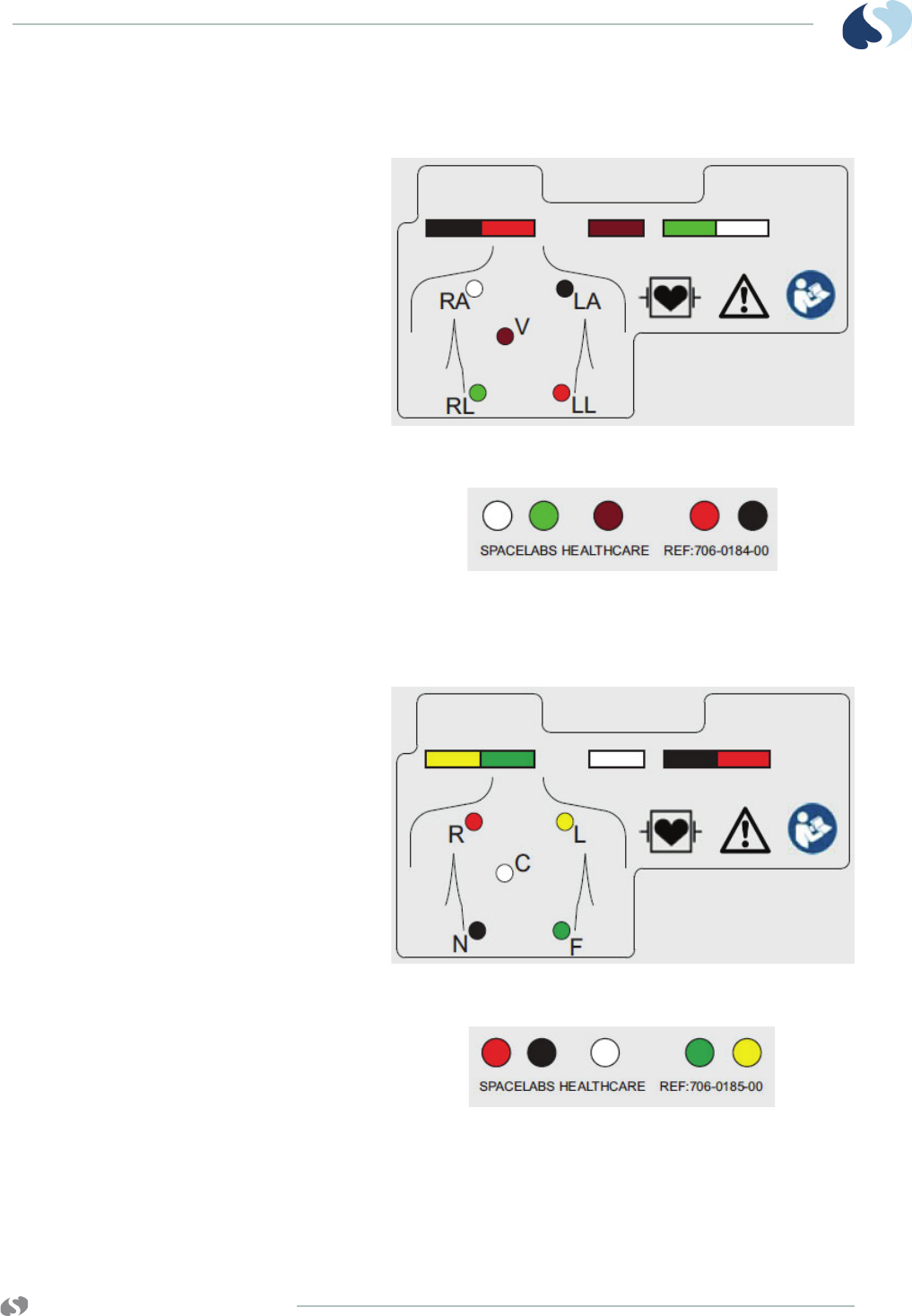
AHA/AAMI Leadwire Labels
Figure 2-4 5-lead AHA/AAMI color codes label on rear of transmitter
Figure 2-5 5-way AHA/AAMI label on front of grouper
IEC Leadwire Labels
Figure 2-6 5-lead IEC color codes label on rear of transmitter
Figure 2-7 5-way IEC color codes label on front of grouper
www.spacelabshealthcare.com
2-6
TELEMETRY TRANSMITTER (96281) ABOUT THE TRANSMITTERS
Telemetry Channel Label
Note:
“Ch.” refers to the channel. The label includes a barcode on the
96281 devices.
Lead Availability
ECG lead availability depends on which electrodes are connected to
a transmitter, and whether the transmitter is a Narrowband device
(option N), or a Wideband device (option W).
Table 2-2 and Table 2-3 detail lead availability for narrowband and
wideband transmitters, respectively, based on which electrodes are
connected.
Notes:
• Augmented leads aVR, aVL and aVF are only available at the
monitor when leads I, II, and III are all available.
• For optimum performance, the right leg electrode should
always be connected.
• If an electrode is not connected, its lead fault indicators will
flash on and off at the transmitter.
• If there are no leads available, all lead fault indicators will flash
on and off at the transmitter.
• The headings for each electrode list the AAMI and IEC lead
designations (the IEC designations are in parentheses).
• If a lead is not available, the monitor will either show a blank
or switch to an alternate available lead.
• Leads are only shown on a transmitter if the transmitter
includes an optional display.
• If a lead is not available, the transmitter makes the ECG
waveform area blank within the on-transmitter display.
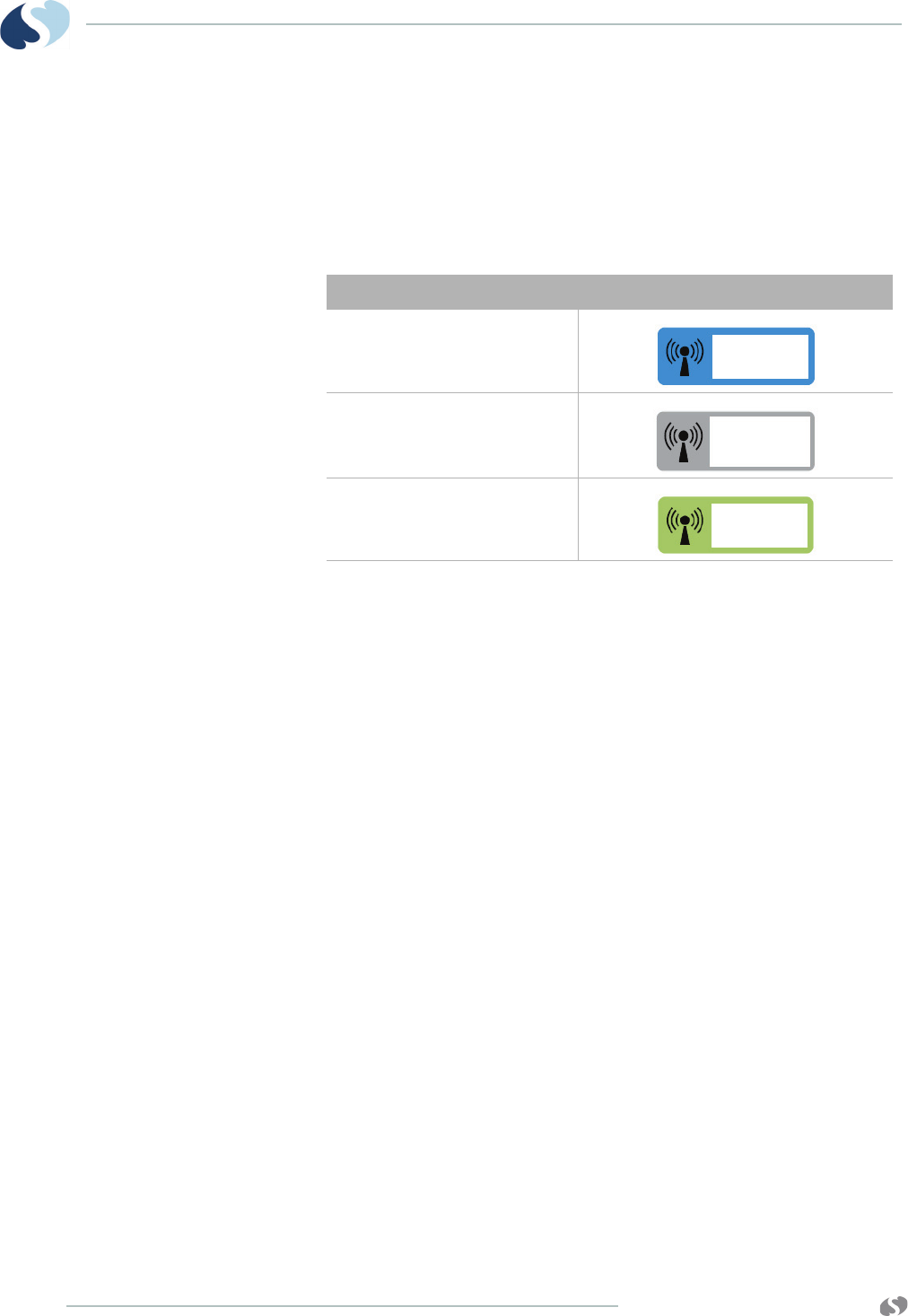
Table 2-1 Labels for Radio Frequency Channels
Radio Frequency (RF) Channel Label Border Color
608-614 MHz
433-434 MHz
1395-1431.5 MHz

www.spacelabshealthcare.com 2-7
TELEMETRY TRANSMITTER (96281) ABOUT THE TRANSMITTERS
• Other combinations of disconnected electrodes yield no
useful data, resulting in no lead availability at either the
monitor or the transmitter.
Table 2-2 Lead Availability with Narrowband transmitters (96281-xxxNx)
Connected Electrodes (X) Available leads at the
monitor
Shown leads
at the
transmitter
RA
(R)
LA
(L)
LL
(F)
RL
(N)
V
(C)
X X X X X II, V I, II, III, V
X X X X II, V I, II, III, V
X X X X I, II, III, aVR, aVF, aVL I, II, III
X X X I, II, III, aVR, aVF, aVL I, II, III
X X X X III III
X X X III III
X X X III III
X X III III
X X X X II II
XXXII II
XXXII II
X X II II
XX XXI I
XX X I I
XX XI I
XX I I
Table 2-3 Lead Availability with Wideband transmitters (96281-xxxWx)
Connected Electrodes (X) Available leads at the
monitor
Shown leads
at the
transmitter
RA
(R)
LA
(L)
LL
(F)
RL
(N)
V
(C)
X X X X X I,II,III,V, aVF, aVL, aVR I, II, III, V
X X X X I,II,III, aVF, aVL, aVR I, II, III
X X X X I,II,III, aVF, aVL, aVR I, II, III
X X X X III III
X X X III III
X X X III III
X X X X II II
XXXII II

www.spacelabshealthcare.com
2-8
TELEMETRY TRANSMITTER (96281) ABOUT THE TRANSMITTERS
XXXII II
XXX II II
XX XXI I
XX XI I
XX X I I
Table 2-3 Lead Availability with Wideband transmitters (96281-xxxWx)
Connected Electrodes (X) Available leads at the
monitor
Shown leads
at the
transmitter
RA
(R)
LA
(L)
LL
(F)
RL
(N)
V
(C)

www.spacelabshealthcare.com 3-1
TELEMETRY TRANSMITTER (96281)
ECG and SpO2
ECG Overview
ECG monitoring begins when the system detects a signal through
the connection of ECG electrodes or by installation of a battery into
a telemetry transmitter. Please refer to the operations manual for
your patient monitor for complete information on ECG and SpO2
setup.
Telemetry ECG monitoring requires the minimum conditions from
the list that follows:
• ECG electrodes must be properly attached to the leadwires.
• The leadwires must be properly attached to the telemetry
transmitter.
• The telemetry transmitter must have functional batteries.
• The telemetry receiver module must be:
- Inserted in the receiver housing that is connected to a central
station, or
- Connected to a monitor that is powered ON.
- Configured to the same channel number as its corresponding
telemetry transmitter.
- Connected to a Spacelabs Healthcare diversity antenna.
Patient Preparation and Electrode Application
Use silver/silver-chloride electrodes or their equivalent, and always
connect all electrodes required for a particular lead. Missing
electrodes may result in the loss of the ECG waveform.

www.spacelabshealthcare.com
3-2
TELEMETRY TRANSMITTER (96281) ECG AND SPO2
Note:
Use only Spacelabs Healthcare-recommended electrodes. Some
electrodes may polarize and create large offset potentials. This
can compromise recovery time after application of defibrillator
pulses. Squeeze-bulb electrodes, commonly used for diagnostic
ECG recordings, may be particularly vulnerable to this effect.
Noise on ECG signals, especially noise that resembles actual cardiac
waveforms, is a frequent cause of false alarms. Some of this noise
may be because of electrode positioning, patient movement or
intermittent signal connections (either of electrode to skin or of
leadwires to electrodes). You can eliminate some of this noise (and
many of these false alarms) by paying careful attention to skin
preparation and electrode application.
The telemetry transmitter is color-coded to match the color of the
leadwires. Table 3-1 on page 3-3 lists leadwire color and identifier
codes.
To Set Up ECG Monitoring
When attaching leadwires to the telemetry transmitter, use the color
coding and/or leadwire identifier code to ensure that the correct
connections are made.
ECG electrodes have a column of conductive gel that is surrounded
by an adhesive surface. The condition of the electrode’s gel column
directly affects the quality of the ECG signal. For example, more
noise appears on the ECG signal if gel is displaced (or air is trapped)
when you apply an electrode to the patient. Key points to remember
include:
• Before using electrodes, verify that they have not expired
and that the conductive gel is not dry. Replace the
electrodes if necessary.
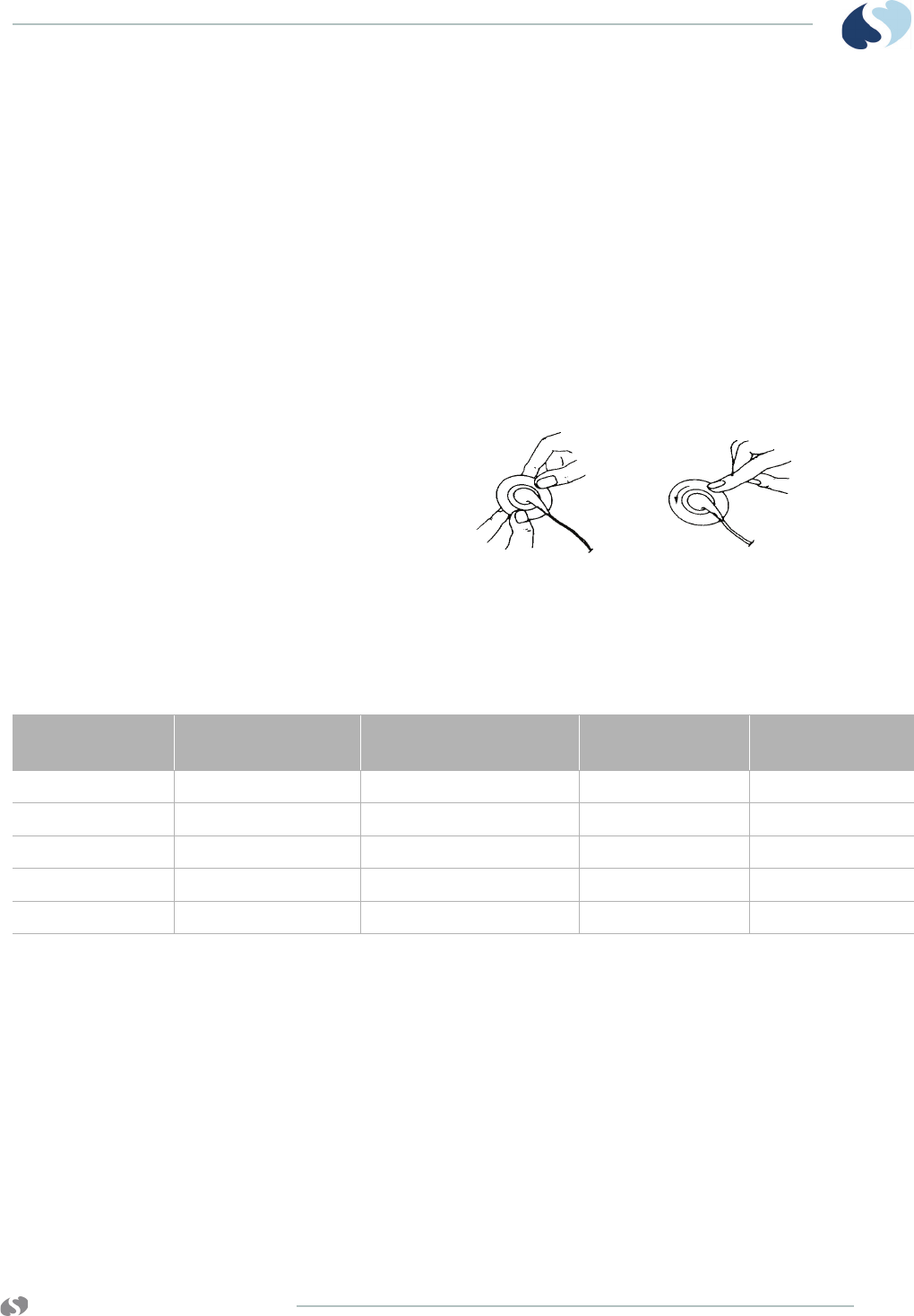
• Always attach the electrode to its leadwire before applying
the electrode to the patient (refer to Figure 3-1). Do not
apply pressure directly over the electrode’s gel column.
• Press firmly around the outer edge of the electrode’s
adhesive surface to ensure that the electrode is securely
attached to the patient.
• To minimize muscle artifact, place electrodes over flat, non-
muscular areas of the body (refer to Figure 3-2). This is
important for telemetry patients who are usually ambulatory.
• After electrodes and leadwires are attached, add a stress
loop (a loop of leadwire taped close to its electrode) to
minimize stress or pulling on the electrode itself. This will
improve ECG signal quality, particularly for ambulatory
patients.
Note:
Spacelabs Healthcare recommends that electrodes be replaced
after 24 to 48 hours of use.
www.spacelabshealthcare.com 3-3
TELEMETRY TRANSMITTER (96281) ECG AND SPO2
To prepare the patient
• Wash the area with soap and water.
• If necessary, shave the area where you plan to position the
electrodes.
• Clean the skin with alcohol.
• Dry the skin thoroughly.
• Abrade the skin.
To apply ECG electrodes
• Attach an electrode to a leadwire.
• Apply the electrode to the patient’s skin.
Figure 3-1 Electrode application
1 Attach the electrode to the leadwire.
2 Apply the electrode to the skin.
12
Table 3-1 Leadwire Color and Identifier Codes
AAMI Electrode
Identifier AAMI Color Code Electrode Placement IEC Electrode
Identifier IEC Color Code
RA White Right Arm R Red
LA Black Left Arm L Yellow
LL Red Left Leg F Green
RL Green Right Leg N Black
VBrown Chest CWhite

www.spacelabshealthcare.com
3-4
TELEMETRY TRANSMITTER (96281) ECG AND SPO2
Adult Electrode Placement
Figure 3-2 Adult electrode placement
Note:
For best ECG performance, the right leg electrode should always
be connected.
ECG Problem Solving
If ECG signal quality is poor (indicated by wandering baseline,
excessive noise, or muscle or respiration artifact), try the solutions
from the list that follows:
• Make sure that silver/silver-chloride electrodes are being used.
• Make sure that the patient's skin is properly prepared.
• Make sure that the skin is dry.
• Make sure that all electrodes are firmly attached and in good
condition.
• Make sure that the electrodes are positioned on a flat, non-
muscular area.
1RL
2RA
3LA
4 LL
5 - 9 V1 through V6
5 Electrodes
I, II, III, aVR, aVL, aVF,
V1 - V6
32
5
4
1
9
6
7
8
8
With 5-electrodes, one precordial lead
is selected by appropriate placement
of the chest (V) electrode.

www.spacelabshealthcare.com 3-5
TELEMETRY TRANSMITTER (96281) ECG AND SPO2
• Make sure that leadwires are properly fastened and in good
condition.
• If these actions fail to resolve the problem, select a different lead.
Lead Fault Indication
The lead fault indication messages listed here are on the central
monitor/station and not the transmitter display.
The message CHECK XX (where XX identifies the failed or missing
electrode) appears in the ECG waveform zone if a lead fault occurs.
If automatic lead switching is enabled, another lead is automatically
selected so that monitoring is uninterrupted.
A LEADS OFF message appears if automatic lead switching is
disabled.
Noise Detection
A NOISY SIGNAL message appears in the ECG waveform zone of the
central monitor/station if noise is detected. If both the first and
second lead are noisy, the module suspends processing temporarily.
If the noise persists for 10 seconds, the system initiates an alarm. The
message and alarm cease when the noise disappears.
Notes:
• If monitoring is interrupted because of overload or saturation
of the input amplifiers, including overload caused by a
defibrillator discharge, the ECG waveform is shown as an
out-of-range signal accompanied by a NOISY SIGNAL or
HR UNAVAILABLE message.
• If the waveform shown does not appear noisy, but the NOISY
SIGNAL message persists, check all leads for noise before
calling a qualified field service engineer.
False Alarms
Careful attention to skin preparation and electrode application,
especially during setup, will reduce false alarms.
If false alarms occur, check for the issues from the list that follows:
• Excessive noise on the signal (the most common cause of false
alarms). Electrodes that are placed incorrectly over muscles, or a
poor lead connection, can cause significant noise when the
patient moves.
• Heart rate limits set too close to patient's heart rate. Adjust the
limits as necessary.

www.spacelabshealthcare.com
3-6
TELEMETRY TRANSMITTER (96281) ECG AND SPO2
SpO2Overview
Pulse oximetry is used to continuously and noninvasively measure
functional oxygen saturation in the blood. Pulse oximetry is
measured by using changes in light absorption, as the light passes
over a pulsating arteriolar bed. Pulse oximetry is also used to
continuously and noninvasively measure pulse rate, using an SpO2
sensor.
Note:
SpO2 functionality is only available on the 96281-C telemetry
transmitter.
The pulse oximetry sensor contains two light-emitting diodes
(LEDs). These LEDs emit specific wavelengths of red and infrared
light, which are measured by a photo detector. The monitor shows
this functional oxygen saturation as percent SpO2.
The amount of light absorbed by the arteriolar bed varies during
pulsations. During systole, a pulse of arterial blood enters the
vascular bed, increasing the blood volume and light absorption.
During diastole, blood volume and light absorption reach their
lowest point. The pulse oximeter’s SpO2 measurement depends on
the difference between the maximum and minimum absorption
(systole and diastole, respectively).
Traditional Pulse Oximetry
Traditional pulse oximetry is based on two principles:
• Oxyhemoglobin and deoxyhemoglobin differ in their absorption
of red and infrared light (spectrophotometry).
• The volume of arterial blood in tissue and the light absorbed by
the blood changes during the pulse (plethysmography).
Traditional pulse oximetry assumes that all of the pulsations in the
light absorbance signal are due to oscillations in the arterial blood
volume. Therefore, the blood flow in the region of the sensor passes
entirely through the capillary bed. Concentrating on the light
absorption of pulsatile arterial blood eliminates the effects of non-
pulsatile absorbers (such as bone, tissue, pigmentation, and venous
blood), which normally absorb a constant amount of light over time.
Oxyhemoglobin and deoxyhemoglobin differ in light absorption. The
amount of red and infrared light absorbed by blood can be used to
calculate the ratio of oxygenated hemoglobin to total hemoglobin in
arterial blood, at each of two wavelengths (such as 660 nm and 940
nm). This ratio is translated into the functional oxygen saturation
(SpO2) measurement that the monitor shows.
Note:
•Because SpO
2 measurements depend upon light from a
sensor, excessive ambient light can interfere with the pulse
oximeter’s measurements.
www.spacelabshealthcare.com 3-7
TELEMETRY TRANSMITTER (96281) ECG AND SPO2
• This pulse oximeter measures functional saturation, which is
essentially the percentage of hemoglobin that can transport
oxygen (oxyhemoglobin). Pulse oximeters do not detect
significant amounts of dysfunctional hemoglobins, such as
carboxyhemoglobin or methemoglobin, which cannot carry
oxygen. Saturation measurements from pulse oximeters
cannot be directly compared to measurements from a
laboratory co-oximeter. Co-oximeters provide a fractional
saturation (SaO2) value by measuring each type of
hemoglobin individually. This fractional value is the ratio of
oxygenated hemoglobin to all measured (oxygenated and
dysfunctional) hemoglobins.
• A pulse oximeter SpO2 measurement may not match the
saturation calculated from a blood gas partial pressure of
oxygen (PO2). The most likely reason is that the calculated
saturation value was not corrected to reflect the effects of
variables that alter the relationship of PO2 and pH. Such
variables can include temperature, the partial pressure of
carbon dioxide (PCO2), 2,3-DPG, and fetal hemoglobin.
Refer to your hospital’s protocols for specific instructions.
Warnings and Cautions for SpO2
This section includes warnings and cautions specifically related to
SpO2. Also included are cautionary disclosures that apply to
electrodes and leadwires, defibrillators (including automatic
implantable cardiac defibrillators), pacemakers, electrosurgical
activity, several physiological parameters, or to the monitoring
system itself.
• A pulse oximeter should be considered an early warning
device and should NOT be used as an apnea monitor. If a
trend toward patient deoxygenation is indicated, blood
samples should be analyzed by a laboratory co-oximeter
to completely understand the patient's condition.
• Pulse rate measurement is based on the optical detection
of a peripheral flow pulse and therefore may not detect
certain arrhythmias. The pulse oximeter should not be
used as a replacement or substitute for ECG-based
arrhythmia analysis.
• Carboxyhemoglobin may erroneously increase readings.
The level of increase is approximately equal to the amount
of carboxyhemoglobin present. Dyes or any substance
containing dyes that change usual arterial pigmentation
may cause erroneous readings.

www.spacelabshealthcare.com
3-8
TELEMETRY TRANSMITTER (96281) ECG AND SPO2
• Inaccurate measurements may be caused by:
- Significant levels of dysfunctional hemoglobins
(e.g., carboxyhemoglobin or methmoglobin).
- Intravascular dyes such as indocyanine green or
methylene blue.
- Exposure to excessive illumination, such as surgical
lamps (especially ones with a xenon light source),
bilirubin lamps, fluorescent lights, infrared heating
lamps, or direct sunlight (exposure to excessive
illumination can be corrected by covering the sensor
with a dark or opaque material).
- Venous pulsations.
- Placement of a sensor on an extremity with a blood
pressure cuff, arterial catheter, or intravascular line.
• Do not use the oximetry sensors during MRI scanning.
Induced current could potentially cause burns.
• Tissue damage can be caused by incorrect application or
by wrapping the sensor too tightly for example. Inspect
the sensor site as directed in the sensor directions for use
to ensure skin integrity and to ensure correct positioning
and adhesion of the sensor.
• Applying an oximetry sensor incorrectly or leaving the
sensor in place for too long may cause tissue damage,
especially when monitoring neonates.
• Check the sensor site frequently, and do not allow the
sensor to remain on one site for too long. Refer to the
instructions from the sensor manufacturer for more
information.
• Do not use a sensor with exposed optical components.
•SpO
2 functional test fixtures can not be used to assess
accuracy of a pulse oximeter sensor or monitor.

www.spacelabshealthcare.com 3-9
TELEMETRY TRANSMITTER (96281) ECG AND SPO2
Electrodes, Leadwires, Sensors, and Sensor Cables
• Carefully route all cables between the patient and the
monitor to reduce the possibility of patient entanglement
or strangulation.
• Signals resulting from devices such as Implantable
Cardiac Defibrillators (ICD) may momentarily blank the
ECG waveform rather than show an out-of-range signal.
In such cases it may not be apparent that the ICD has
triggered and the condition of the patient should be
checked. In all instances of the ICD being triggered,
the monitor will reshow the ECG waveform within five
seconds.
• ECG alarms for ventricular fibrillation and asystole remain
active while the patient’s rate and morphology are being
learned (for example, following a lead switch or use of the
RELEARN feature). ECG alarms for high rate, low rate,
ventricular run, couplet, VE/minute, atrial fibrillation,
pause, and PSVT are not reactivated until the learning
process ends.
• To ensure against any possibility of electric shock, do not
touch lead electrodes or the monitor during defibrillation.

www.spacelabshealthcare.com
3-10
TELEMETRY TRANSMITTER (96281) ECG AND SPO2
Electrodes, Leadwires, Sensors, and Sensor Cables
Note:
For cleaning and disinfecting procedures, refer to the Cleaning,
Disinfecting, and Sterilization chapter of this manual.
•Visually inspect each leadwire for obvious damage and
replace as needed.
•Use only patient cables and leadwires specified by
Spacelabs Healthcare. Other cables and leadwires may
damage the monitor during defibrillation and may also
change the required input impedance and DC offset
voltage, affecting performance.
•Do not use stainless steel electrodes.
•Do not allow conductive parts of electrode leads or
connectors, including the neutral electrode, to contact
other conductive parts, including the ground.
•Use only patient sensors specified by Spacelabs
Healthcare. If you use sensors other than those specified,
it may degrade SpO2 performance and could damage the
monitor during defibrillation.
•Spacelabs Healthcare recommends the use of sensors
repaired or remanufactured by the original manufacturer
only.
•Never attach an SpO2 sensor to a limb being monitored
with a blood pressure cuff or a limb with restricted blood
flow.
•A poorly applied sensor may give incorrect saturation
values. The Sensorwatch signal-strength indicator is used
to identify a poorly applied sensor or a poorly chosen
site. Refer to Using the Sensorwatch Feature on
page 3-14 for additional information.
•Choose a site with sufficient perfusion to ensure accurate
oximetry values.
•Make sure the electrodes and skin are dry.
•An adapter cable is required between the sensor and the
transmitter. Do not discard the adapter cable when you
have finished using a disposable oximetry sensor.
Disconnect the sensor cable from the adapter cable
before discarding the sensor.

www.spacelabshealthcare.com 3-11
TELEMETRY TRANSMITTER (96281) ECG AND SPO2
Setting Up SpO2 Monitoring
1Connect the SpO2 adapter cable to the patient-worn telemetry
transmitter.
2Attach the sensor to the patient and connect the sensor cable to
the SpO2 adapter cable.
3Initiate ECG monitoring on the patient monitor.
4Touch ECG.
5Touch CHANNEL FORMAT.
6Touch SpO2/ON.
Ensuring Accurate SpO2 Monitoring
Each sensor requires site-specific application procedures. The
quality of the patient’s pulse oximetry measurements and pulse
signals may be adversely affected by certain environmental factors,
by oximetry sensor application errors, and by patient conditions.
Any of these factors can interfere with the monitor’s ability to detect
and show measurements and may result in a loss-of-pulse condition.
If the SpO2 measurement does not seem reasonable, first check the
patient’s vital signs by alternate means and then check the pulse
oximeter for proper operation.
Patients with anemia and/or significant concentrations of
dysfunctional hemoglobins (such as carboxyhemoglobin,
methemoglobin, and sulphemoglobin) may appear to have normal
saturation values while actually being hypoxic. Further assessment,
using means other than pulse oximetry, is recommended for such
patients.
• For anemic patients, this condition occurs because patients have
decreased arterial oxygen contents.
• For patients with dysfunctional hemoglobins (that are unable to
carry oxygen), this condition occurs because less functional
hemoglobin is available to carry oxygen.
Other patient conditions that may result in inaccurate
measurements or a loss-of-signal condition during operation
include:
•Low perfusion
• Dark pigment
• Prolonged and/or excessive patient movement
Hemoglobin levels below 5 g/dl may prevent the monitor
from providing SpO2 values.
www.spacelabshealthcare.com
3-12
TELEMETRY TRANSMITTER (96281) ECG AND SPO2
• An arterial occlusion (blocked artery) proximal to the sensor
• Venous pulsations
• Wrapping the sensor too tightly around the patient’s digit or
other extremity
• Placing the sensor on an extremity with a blood pressure cuff,
arterial catheter, or intravascular line
• Inflating a blood pressure cuff on the limb to which the sensor is
attached
External factors that may adversely affect the accuracy of
oximetry readings include:
• High ambient lighting
• High-frequency electrical noise, such as electrosurgical units and
defibrillators
• The presence of intravascular dyes, such as indocyanine green or
methylene blue, or externally applied coloring, such as nail polish
or pigmented creams
• The patient has hypotension, severe vasoconstriction, severe
anemia, or hypothermia
• The patient is in cardiac arrest or is in shock
Taking the actions that follow may improve SpO2 performance:
• Select an application site with unrestricted blood flow.
• Do not select a site near potential electrical interference (e.g.,
electronic equipment, electrosurgical units, other power cords).
If possible, remove these electrical noise sources from the area.
• If artificial nails or externally applied coloring agents such as nail
polish are present, select another site or remove the polish/
artificial nails.
• If necessary, wipe the sensor site for 20 to 30 seconds with a
70% isopropyl alcohol pad to improve performance.
• Apply the sensor correctly, ensuring that the LEDs and the photo
detector are properly aligned directly opposite each other,
preferably on a site that minimizes the distance between the
emitter and photodetector. Periodically check to ensure that the
sensor remains properly positioned on the patient.
• Do not restrict blood flow when securing a sensor with tape.
Sources of high ambient light such as direct sunlight, surgical
lights (especially those with a xenon light source), bilirubin
lamps, fluorescent lights, and infrared heating lamps can
interfere with an SpO2 sensor’s performance and result in
inaccurate measurements. When using SpO2 under such
conditions, this interference can be reduced by covering the
application site with an opaque material and by ensuring that
the sensor is properly applied.

www.spacelabshealthcare.com 3-13
TELEMETRY TRANSMITTER (96281) ECG AND SPO2
• If high ambient light is affecting measurements, ensure that the
sensor is properly applied and then cover the application site
with an opaque material such as a blanket or towel. Failure to do
this may result in inaccurate measurements.
• Maintain a minimum signal level above the Sensorwatch bar.
If patient movement presents a problem, one or more of the
actions that follow may correct it:
• Verify that the sensor is properly and securely applied.
• Move the sensor to a less active site; to reduce or eliminate
motion artifact, the application site should remain as immobile as
possible.
• Use an adhesive sensor that tolerates some patient motion.
• Use a new sensor with fresh adhesive backing.
• A patient may be sensitive to the SpO2 sensor LED heat. If the
sensor causes patient discomfort, move the sensor to a different
location.
SpO2 and Pulse Rate Specifications
Displayed Range
SpO2 (functional) 0% - 100%
Pulse Rate (bpm) 30- 240 bpm
Resolution
SpO2 (functional) 1%
Pulse Rate (bpm) 1 bpm
Table 3-2 Pediatric or Adult SpO2 and Pulse Rate Accuracy
Parameter Patient Type Signal Condition Range Accuracy
SpO2
(functional)
Pediatric or Adult No motion and normal perfusion 70-100
0-69
+/- 2% unspecified
Pulse Rate
(bpm) Pediatric or Adult No motion and normal perfusion 30-240 +/- 3 bpm
Table 3-3 Neonate SpO2 and Pulse Rate Accuracy
Parameter Patient Type Signal Condition Range Accuracy
SpO2
(functional)
Neonate No motion and normal perfusion 70-100
0-69
+/- 3.25%
unspecified
Pulse Rate
(bpm) Neonate No motion and normal perfusion 30-240 +/- 3 bpm
www.spacelabshealthcare.com
3-14
TELEMETRY TRANSMITTER (96281) ECG AND SPO2
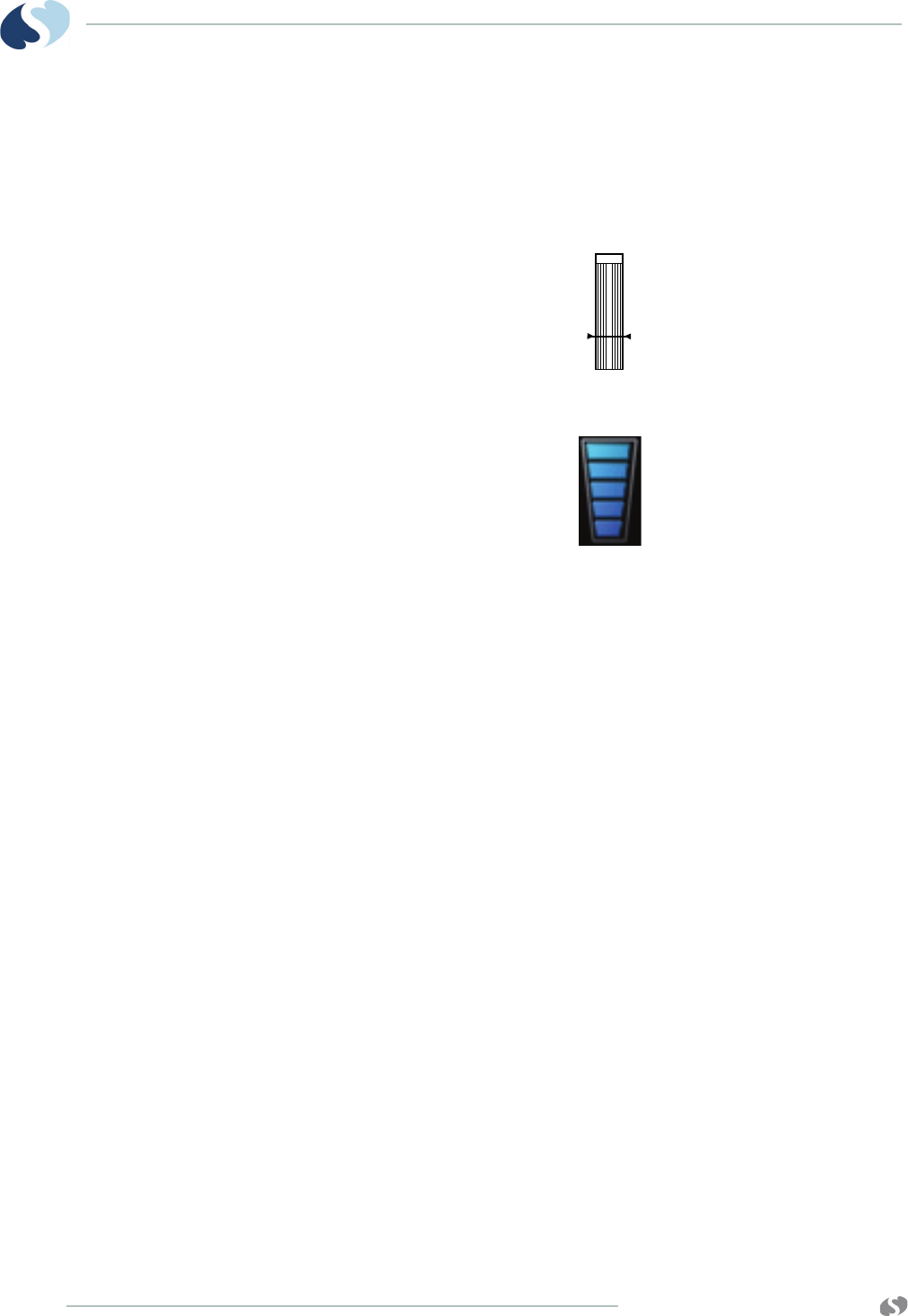
Using the Sensorwatch Feature
The Sensorwatch feature provides a graphical presentation of the
amplitude of the signal received from the sensor. It can be used to
determine the best sensor site and application.
Figure 3-3 SpO2 Sensorwatch bar on the 91387-38 central monitor
Figure 3-4 SpO2 Sensorwatch symbol on the 96281-C telemetry
transmitter.
Changes in the bar’s shaded level signify changes in the patient’s
perfusion or changes in the application of the sensor. The horizontal
line in the bottom fourth of the bar is used in Spacelabs Healthcare
SpO2 technology only and represents the minimum signal level that
results in accurate saturation values.
When the shading is just below this line, the message LOW SIGNAL
STRENGTH - Reposition or replace sensor appears.
• Reposition the sensor to a different site to provide better
perfusion.
• Reposition the sensor to provide better contact with the skin.
Make sure the LEDs and photo detector are properly aligned.
• Replace a defective sensor.
• Wait for the patient to warm up and for the patient’s perfusion to
increase.

www.spacelabshealthcare.com 3-15
TELEMETRY TRANSMITTER (96281) ECG AND SPO2
Enabling and Adjusting Alarms
Spacelabs Healthcare Technology
Pulse oximetry alarm limits and delays are set internally based upon
defined default values. Refer to the user manuals for your patient
monitor for details on operating system alarms.
To enable and adjust SpO2 alarms (telemetry)
1Touch ECG.
2Touch ALARM LIMITS.
3Touch SPO2 ALARM LIMITS.
4Select SPO2 ALM / ON.
5Select HI=, LO=, ALM DELAY, or MSG ALARM DELAY (if present).
6Use the arrow keys to adjust.
Additional Information for Telemetry Products
When SpO2 alarms are enabled, a bell symbol appears immediately
after the measured SpO2saturation percentage (%).
Data Averaging
Data averaging is performed internally on the telemetry transmitter.
The data averaging feature smooths the oximetry saturation value
by averaging patient input values over several seconds.
Te l e m e t r y
For telemetry monitoring, the heart rate for the display is obtained
directly from the acquired ECG leads. In addition, the pulse rate is
obtained from the SpO2 parameter. SpO2 pulse rate is viewable in
the patient’s trends and on the 96281-C telemetry transmitter.
Heart Rate Averaging
On-Transmitter Heart Rate Display Performance
The 96281-B and 96281-C transmitters can show the patient’s heart
rate when the transmitter is in view mode. The heart rate shown on
the transmitter is to aid patient hook up and is indicative only; it is
not for diagnostic use. The heart rate shown on the transmitter is not
related to the heart rate shown on any central monitor/station. The
www.spacelabshealthcare.com
3-16
TELEMETRY TRANSMITTER (96281) ECG AND SPO2
heart rate is calculated using the QRS complexes detected within
the last five seconds on ECG data. Averaging is performed within
the five second window. The heart rate shown on the screen is
updated approximately every 1.8 seconds.
The on-transmitter heart rate display has been tested according to
IEC 60601-2-27:2011 for:
• Tall T-wave rejection: It rejects T-waves up to 75% of the QRS
complex amplitude,
• Maximum response times, to the nearest second, to step
changes in heart rates:
- 5 seconds when the heart rate changes from 80 beats per
minute to 120 beats per minute.
- 5 seconds when the heart rate changes from 80 beats per
minute to 40 beats per minute.
• Heart rate accuracy and response to irregular rhythms:
The heart rates that show on the display for the four irregular
rhythm test waveforms within the standard are listed in Table 3-
4.
Note:
The on-transmitter heart rate is calculated using the ECG Lead
currently being shown on the transmitter display.
Display Details at the Host Monitor
Signal detection is indicated on your monitor when an ECG signal
appears next to the ECG parameter key in the zone assigned to
receive the transmitted telemetry channel. The transmitter's channel
number is always identified above the waveform, to the left of the
ECG key.
Table 3-4 Heart Rates for Four Irregular Rhythm Test Waveforms
Test Wave for m Heart Rate Shown
On Transmitter
A1 80
A2 63
A3 119
A4 86
The on-transmitter heart rate display accuracy may be
affected by cardiac arrhythmias and pacemaker pulses. The
heart rate shown on a central station or bedside monitor may
similarly be affected. Refer to their manuals for appropriate
details.
www.spacelabshealthcare.com 3-17
TELEMETRY TRANSMITTER (96281) ECG AND SPO2
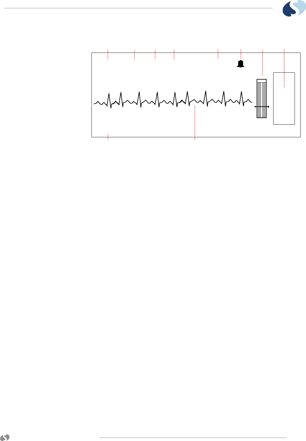
Figure 3-5 Central monitor — split view (SpO2 turned ON)
Notes:
•SpO
2 does not show if it is turned OFF.
• A bell symbol follows the percent (%) symbol if the SpO2
alarm is enabled.
1 Current heart rate
2 Abnormal beats per minute counter
3 ECG lead designator
4 SpO2 reading
5 Telemetry channel number
6 ECG rate alarm limits. Split-view central monitors show a
bell symbol when alarms are enabled.
7 Sensorwatch signal strength indicator
Shaded area (waveform index, WFI) expands up
proportionally to signal strength; horizontal line indicates
minimum signal level.
No shading (lowest waveform index) corresponds to no
detected signal strength or a faulty sensor.
8 ECG key for first lead
9 Bed/patient ID
10 ECG waveform for first lead
Printing SpO2 Waveforms
This feature is not supported in telemetry products.
1234 5678
HR=70 A=3 II 98% 2241
E
C
G
BED 01
910

www.spacelabshealthcare.com
3-18
TELEMETRY TRANSMITTER (96281) ECG AND SPO2
SpO2 Messages at the Host Monitor
When a status message appears, the saturation value and pulse rate
immediately change to ???. An alarm may occur if your module is
configured to do so. Depending on the configuration and
option purchased, this alarm may not occur until after the message
alarm delay time has elapsed.
Telemetry products use different text for SpO2 status messages
than non-telemetry products. Telemetry products also show status
messages within the ECG display zone, therefore, the ECG alarm
messages that follow take priority over other SpO2 messages.
• LEADS OFF
• NOISY SIGNAL
• ECG ALARMS SUSPENDED
Refer to the customer documentation for your monitor for complete
information on potential status messages which may appear at a
host monitor that is configured with a 96281-A, 96281-B, 96281-C
telemetry transmitter.
When a status message appears, the saturation value and pulse rate
immediately change to ???. An alarm may occur if your module is
configured to do so. Depending on the configuration and
option purchased, this alarm may not occur until after the message
alarm delay time has elapsed.
Telemetry products use different text for SpO2 status messages
than non-telemetry products. Refer to Table 3-5 for interpretations
of the telemetry messages.
Telemetry products also show status messages within the ECG
display zone, therefore, the ECG alarm messages that follow take
priority over other SpO2 messages.
•LEADS OFF
• NOISY SIGNAL
• ECG ALARMS SUSPENDED
Status messages indicate problems or conditions that may
affect accurate monitoring values. Do not ignore these
messages. Correct any fault before continuing.
Table 3-5 Telemetry Message Equivalents
Telemetry SpO2 Message
SPO2 SENSOR DISCONNECTED
SPO2 FAULTY SENSOR
SPO2 SENSOR DISCONNECTED

www.spacelabshealthcare.com 3-19
TELEMETRY TRANSMITTER (96281) ECG AND SPO2
SENSOR DISCONNECTED — Check connection at adapter cable
This message and alarm indicate that the sensor is either
disconnected or the wiring is faulty.
• Check for proper sensor connection to the adapter cable.
• If the message persists, replace the sensor and/or the adapter
cable.
SENSOR OFF PATIENT — Check connection at patient
• The telemetry transmitter does not detect a valid sensor input
signal. Check the patient for proper sensor placement.
• The tissue between the LED and photodiode is too transmissive.
If the sensor placement seems correct and the message persists,
try a sensor site with a thicker tissue bed.
Note:
This message is not available with all SpO2 sensors.
INSUFFICIENT SIGNAL — Reposition or replace sensor
• Insufficient signal for proper operation, indicated by a low
deflection on the Sensorwatch signal strength bar.
• Poor sensor application or site. Correctly reapply or reposition to
a better perfused site, or massage the site.
• If the message persists, then replace the sensor.
LOW SIGNAL STRENGTH — Reposition or replace sensor
When this message appears, the saturation and pulse rate continue
to show. However, the Sensorwatch bar flashes as an indication of a
possible error condition.
• Insufficient blood flow between the sensor light emitter and
detector. Move the sensor to an area of higher perfusion.
• Poor sensor application. Reposition to place active components
closer to the skin or locate to a better perfused site.
SPO2 SENSOR OFF PATIENT
SPO2 INSUFFICIENT SIGNAL
SPO2 AMBIENT LIGHT INTF.
SPO2 NOISY SIGNAL
SPO2 INSUFFICIENT SIGNAL
Table 3-5 Telemetry Message Equivalents (Continued)
Telemetry SpO2 Message

www.spacelabshealthcare.com
3-20
TELEMETRY TRANSMITTER (96281) ECG AND SPO2
• The sensor site is below the blood pressure cuff. Move to another
site.
• If the message persists, then replace the sensor.
AMBIENT LIGHT INTERFERENCE — Cover sensor area
• The sensor is receiving external light interference from a bright
light source near the sensor. Shield the sensor from the external
light source.
• The sensor photodiode and LED are misaligned on flexible
sensors, allowing light to enter. Realign the sensor photodiode
with the LED.
• If the message persists, then replace the sensor.
NOISY SIGNAL
• The sensor signal is disturbed by motion or other interference.
Eliminate sensor movement.
• Power cords or other electrically noisy devices are too close to
the sensor. Move the noisy device or move the sensor to another
site.
• If the message persists, then replace the sensor.
FAULTY SENSOR — Replace sensor
• The LED or photodiode (or both) may have failed.
• Ensure the sensor is properly connected, disconnect and then
reconnect the sensor.
• If the error occurs again, replace the sensor and/or sensor
adapter cable.
• If replacing the sensor and/or cable does not correct the
problem, contact your Spacelabs Healthcare Field Service
Engineer.

www.spacelabshealthcare.com 3-21
TELEMETRY TRANSMITTER (96281) ECG AND SPO2
HARDWARE INCOMPATIBILITY — Contact service
The hardware configuration in your module is not compatible with
the programmed software options.
• Contact your Spacelabs Healthcare Field Service Engineer.
Sensors
For SpO2 sensor compatibility, refer to the information that follows.
Spacelabs Healthcare SpO2 Sensors
Please refer to the the accessories in Telemetry Transmitter (96281)
Data Sheet for compatible sensors (for the 96281-C) and adapter
cables.
Additional Information
For additional information about biocompatibility or sensor disposal,
refer to the manufacturer's instructions enclosed with each sensor.
SpO2 Alarm Delays
SpO2 Troubleshooting Guide
Table 3-6 SpO2 Alarms
Alarm Setting Range Alarm Delay
Spacelabs Healthcare
Sat Low 50 to 99% • Less than (15 seconds + user selected alarm delay)
• Alarm delay is user selected from 0 to 30 seconds in
5 second increments.
Sat High 51 to 100% • Less than (20 seconds + user selected alarm delay)
• Alarm delay is user selected from 0 to 30 seconds in
5 second increments.
Clinical Situation Possible Cause Solution
No SpO2 parameter
key in Channel Format
menu
•SpO
2 is not enabled at the
90478 receiver.
• Enable multiparameter
telemetry in the Module
Configuration Manager or
enable the SpO2 display in
the Channel Format menu.

www.spacelabshealthcare.com
3-22
TELEMETRY TRANSMITTER (96281) ECG AND SPO2
SpO2 value shows
as ???
• Sensor is not connected to
the patient.
• Reattach the sensor.
• There is excessive patient
motion.
• Request patient to remain
still while reading is in
progress.
• Module is in the initialization
phase (the first 15 seconds
after sensor application).
• Wait until the initialization is
complete.
• Adapter cable is improperly
connected to the telemetry
transmitter.
• Correctly connect the
adapter cable.
• Sensor is not connected to
the adapter cable.
• Correctly connect the sensor.
• Telemetry low battery
indicator is constantly
illuminated.
• Contact your biomed or a
qualified field service
engineer.
Low signal strength
-OR-
Insufficient Signal
• Sensor placement is not
optimum.
• Move the sensor to a site
which has better perfusion.
• Align the LED with the sensor
photo detector.
• Sensor is placed below the
blood pressure cuff.
• Move the sensor to an
alternate limb.
Intermittent or
complete failure to
operate
• Receiver or transmitter
error.
• Contact your biomed or a
qualified field service
engineer.
Factors causing
significant variances in
sensor accuracy
• Presence of dysfunctional
hemoglobins (COHb,
MetHb).
• Follow hospital procedure for
determining oxygenation in
these patients.
• Presence of intravascular
dyes (indocyamine green,
methylene blue) in the blood
stream.
• Follow hospital procedure for
determining oxygenation in
these patients.
• High ambient light level. • Reduce light levels near the
patient.
• Electrosurgical interference. • Follow hospital procedure for
determining oxygenation in
these patients.
• Patient is significantly
anemic (Hb less than 5 g/dl)
or has received large
amounts of IV solutions.
• Follow hospital procedure for
determining oxygenation in
these patients.
Clinical Situation Possible Cause Solution

www.spacelabshealthcare.com 3-23
TELEMETRY TRANSMITTER (96281) ECG AND SPO2
No SpO2 alarms are
shown
• ECG “Leads Off” condition
exists.
• Re-attach ECG leadwires to
the patient and resume ECG
monitoring.
• Higher priority alarm
condition is present.
• Clear the current alarm
condition and/or re-prioritize
SpO2 alarms in the Module
Configuration Manager.
•When SpO
2 alarms are ON,
all SpO2 alarm conditions
cause the parameter value to
blink according to the alarm
priority set using the Module
Configuration Manager.
FAULTY SENSOR
Replace Sensor
• A faulty or incompatible
sensor is connected to the
adapter cable.
• To clear the message,
connect a known good
sensor to the adapter cable.
• Sensor has failed.
Clinical Situation Possible Cause Solution

www.spacelabshealthcare.com
3-24
TELEMETRY TRANSMITTER (96281) ECG AND SPO2

www.spacelabshealthcare.com 4-1
TELEMETRY TRANSMITTER (96281)
Basic Operations
Getting Started
Device setup must be performed before patient application and, on
appropriate units, the LCD should be visually verified to function
before use on a patient.
Transmitter Batteries
When batteries are installed, the transmitter is continuously ON. If
no batteries are installed, the transmitter is OFF. To extend battery
life, insert batteries only to use the transmitter with a patient.
Remove the batteries when the transmitter is not in use.
Spacelabs Healthcare recommends two AA 1.5-volt alkaline batteries
for standard use in the digital telemetry transmitter for a battery
source of 3 volts. Alternatively, you may use two AA-equivalent
2400 mAH NiMH rechargeable batteries.
Check the battery position and polarity, as shown at the bottom of
the battery compartment on the device. After battery installation,
close and latch the compartment cover. Transmission of telemetry
signals begin as soon as the battery is in place.
Refer to Battery Compartment (96281-A, 96281-B, 96281-C) on
page 4-8 for details on battery compartment labels and
components.

www.spacelabshealthcare.com
4-2
TELEMETRY TRANSMITTER (96281) BASIC OPERATIONS
• Batteries exposed to short circuit, high temperature, or
fire may leak, vent, or explode.
• Do not use any transmitter that has been compromised by
liquid ingress.
• When the transmitter is not in use, remove the batteries.
Store the transmitter without the batteries.
• Users should inspect batteries before using them within
the transmitter—do not use any batteries that appear to
be damaged or have been subject to misuse.
• Do not use any transmitter that has been compromised by
liquid ingress. If fluid has collected in the battery
compartment, clean and dry it before use. If the
transmitter has been immersed in liquid, it must be
thoroughly dried before use. Not doing so may prevent
the transmitter from working properly. If the SpO2 sensor
has been immersed in liquid, it should be dried and
inspected for proper operation and replaced if necessary.
• Do not attempt to use depleted batteries or mix different
types of batteries. Doing so may result in the telemetry
transmitter being unable to accurately determine the
battery condition and prevent the transmitter from
working properly. If the battery low indicator flashes as
soon as batteries are inserted, then they are too depleted
to be used and the transmitter will not work properly.
Replace with new or fully-charged batteries immediately.

www.spacelabshealthcare.com 4-3
TELEMETRY TRANSMITTER (96281) BASIC OPERATIONS
Notes:
The description that follows of transmitter operation is valid only
for two AA 1.5-volt alkaline or two AA-equivalent 2400 mAH
NiMH rechargeable batteries and does not apply to any other
type of battery.
• When a low battery condition is detected, the orange battery
status indicator illuminates on the front cover of all three
transmitter models: 96281-A, 96281-B, 96281-C. In addition,
a red battery symbol appears in the display of the 96281-B
and 96281-C transmitters.
• Used batteries must be properly disposed of or recycled
according to national and/or local regulation.
• Refer to the product service manual for more details.
Host Monitors
The 96281 telemetry transmitter is compatible with the Ultraview SL
3800-38/-39 central monitor and the Ultraview and Ultraview SL
line of bedside monitors. For information on configuring battery
alarm status, enabling and adjusting alarms, assigning telemetry
channels, status or interference messages, refer to the operations
and service manuals for the specific monitor in use with the
telemetry transmitter devices.
If you use Ultraview SL 3800-38 or 3800-39 central monitor, refer to
the Ultraview SL Operations Manual, 91387 Service Manual, and to
the Clinical Parameters Operations Manual for more information.
•Obey the battery manufacturer’s recommended handling
procedure.
•Collect and transport batteries in a manner that prevents
short circuit, compacting, mutilation, or any other abuse
that would compromise the physical integrity.
•Clean the transmitter case with the battery door closed. If
fluid or other contaminants have collected in the battery
compartment, clean and dry it before use.
•Inspect and check the transmitter for damage prior to
every procedure.
•Use either new alkaline batteries or fully-charged 2400
mAH NiMH rechargeable batteries for each and every new
procedure.
•Clean the transmitter after each use. For preventive
maintenance instructions, refer to the Telemetry
Transmitter (96281-A, 96281-B, 96281-C) Service Manual
(P/N 070-2408-xx), located on the Telemetry Service
(9628X) CD-ROM (P/N 084-2202-xx) .
•Make sure that service on the transmitter is performed by
authorized Spacelabs Healthcare service personnel when
repairs are necessary or at suitable intervals.
www.spacelabshealthcare.com
4-4
TELEMETRY TRANSMITTER (96281) BASIC OPERATIONS
Telemetry Receiver Module
The telemetry transmitters are compatible with the 90478 Digital
Telemetry System Receiver and Receiver Housing (90479-A,
90479-B, 90479-C). The receiver housing is related to the central
monitor. The receiver module can go in the housing or in a bedside
monitor.
For detailed information relating to the 90478 and 90479 digital
telemetry systems, refer to Clinical Parameters Operations Manual
located on the Bedside, Central, and Telemetry Systems CD-ROM
and to the Spacelabs Healthcare Service CD-ROM.
Assigning a Telemetry Channel
When connecting a new patient to a transmitter, make sure the prior
patient’s information has been purged at the host monitor.
Your central station can only show a telemetry channel after that
channel has been assigned a specific bed or room number. Refer to
the user manuals for your central monitor or station for information
to assign a specific bed name to a telemetry channel and to assign
the bed to a specific display zone. Your central monitor can be
configured to remember the bed name assigned to individual
telemetry channels. These beds are permanently assigned until
you unassign or reassign them. For more information, refer to the
Ultraview SL Module Configuration Manager System Administration
Guide.
All system connections (except for those related to moving
receivers from one monitor or housing to another) must be
made by trained or qualified personnel only. Changes or
modifications not expressly approved by Spacelabs
Healthcare may void the user’s authority to operate the
equipment.
•Telemetry transmitters have preassigned channel numbers
(frequencies) that cannot be changed. The channel
number is identified on the back cover of the transmitter.
•Only qualified personnel should tune telemetry receiver
modules to receive data from a telemetry transmitter.
Telemetry receiver modules must be used with a
transmitter on the same frequency.
•Qualified service personnel should set the telemetry
receiver’s frequency band via the Module Configuration
Manager feature.
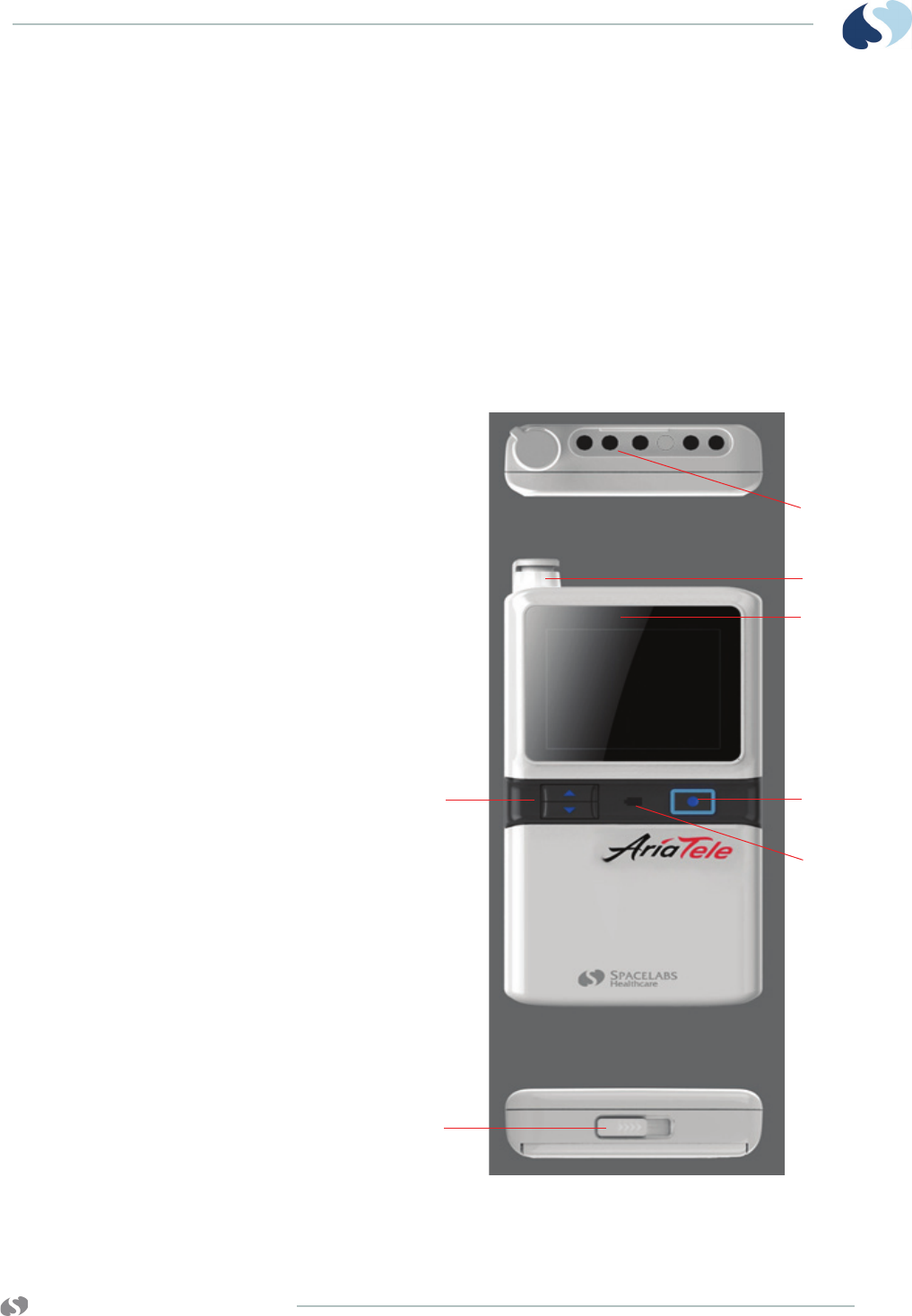
www.spacelabshealthcare.com 4-5
TELEMETRY TRANSMITTER (96281) BASIC OPERATIONS
Basic Components
The 96281-B telemetry transmitter is essentially the same as the
96281-C model, except for the SpO2capability. Thus the
components described in the illustrations of the 96281-C are also
applicable to the 96281-B model except for the SpO2 connector cap.
The 96281-A model is similar to the 96281-B and 96281-C but it does
not include a display or an SpO2 connector cap or functionality
(refer to Figure 4-3 on page 4-7).
Top, Front and Bottom View (96281-C)
Figure 4-1 Top, front, and bottom views (96281-C)
1
3
4
5
7
6
2
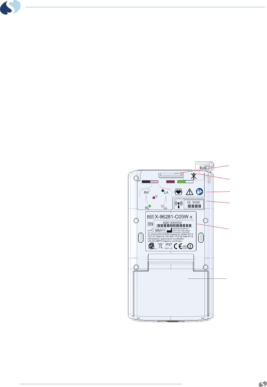
www.spacelabshealthcare.com
4-6
TELEMETRY TRANSMITTER (96281) BASIC OPERATIONS
1 Top view showing lead inputs and SPO2 connector cap
(SPO2 cap on 96281-C only)
2 Front view of SPO2 connector cap (96281-C only)
3 Location on display where lead fault indicators show
(96281-B, 96281-C)
4 Action button
Note:
The nurse may instruct the patient to press the Action button if
he or she experiences any discomfort.
5 Low battery indicator
6 Bottom view of the battery compartment latch
7 Up/down buttons for LCD configuration (96281-B and
96281-C only)
Rear View (96281-C)
Figure 4-2 Rear view (96281-C)
1 Grouper (includes a clip)
2 “Do not modify” symbol (repairs and modifications must
be done by Spacelabs Healthcare authorized personnel)
1
2
3
4
5
6
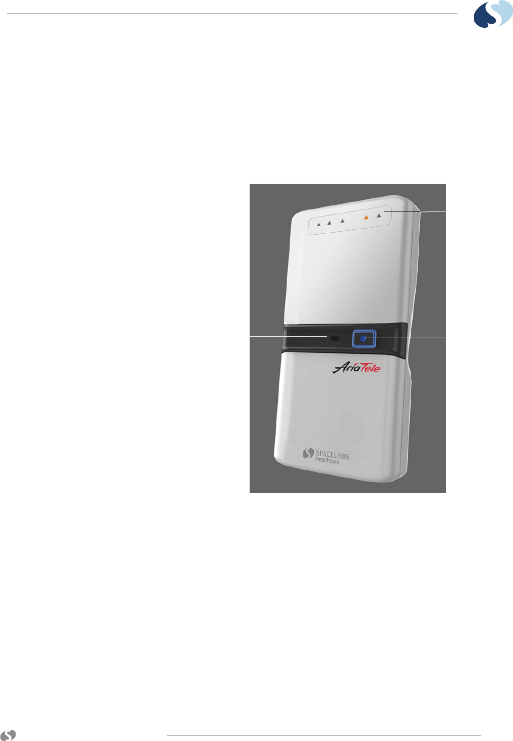
www.spacelabshealthcare.com 4-7
TELEMETRY TRANSMITTER (96281) BASIC OPERATIONS
3 ECG label (includes lead legend and leads placement
diagram)
4 Channel identifier
5 Manufacturing technical label
6 Battery compartment cover
Front View (96281-A)
Figure 4-3 96281-A Telemetry Transmitter
1 Lead fault indicators on 96281-A
(up to five triangular shapes may illuminate when
activated by a lead off condition)
2 Action button
3 Low battery indicator
1
2
3
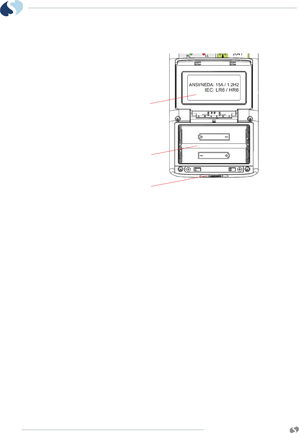
www.spacelabshealthcare.com
4-8
TELEMETRY TRANSMITTER (96281) BASIC OPERATIONS
Battery Compartment (96281-A, 96281-B, 96281-C)
Figure 4-4 Details of battery compartment (cover open)
1 Battery type label affixed to underside of open battery
compartment cover
2 Battery polarity label
3 Battery compartment latch (on bottomside)
1
2
3
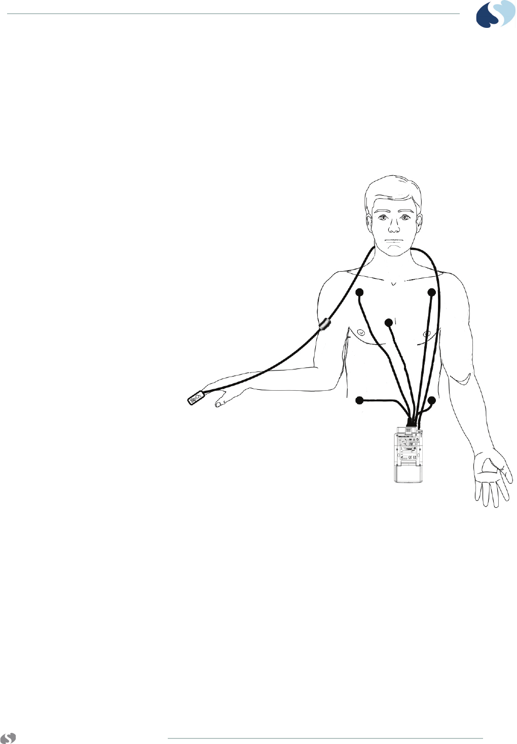
www.spacelabshealthcare.com 4-9
TELEMETRY TRANSMITTER (96281) BASIC OPERATIONS
Selecting Options for Leads
Up to five standard, disposable, silver/silver chloride chest
electrodes are connected to the patient. The ECG leadwires are
attached to these electrodes and connected to the transmitter.
Refer to Figure 4-5 on page 4-9 for leads placement and SpO2
connections.
Figure 4-5 ECG leads placement and SpO2 connections
1 RA
2 LA
3 V
4 LL
5 RL
6 96281-C telemetry transmitter
7 SpO2 sensor
8 SpO2 cable
Monitors and transmitters may be placed in pouches and
attached to the patient’s belt.
12
3
4
6
5
7
8

www.spacelabshealthcare.com
4-10
TELEMETRY TRANSMITTER (96281) BASIC OPERATIONS
Notes:
• If one of the leads fails, a lead fault message shows on the
host monitor.
• If there is no valid lead vector, the message CHAN 1 & 2 -
LEADS OFF shows and an alarm tone sounds only at the host
monitor.
Basic User Actions
The up and down arrow buttons (refer to 7 in Figure 4-1 on page 4-
5) provide navigational control, such as moving through ECG and
SpO2 displays. These up/down buttons are only included on the
96281-B and 96281-C models.
All 96281 devices include the Action button (refer to item 4 in Figure
4-1 on page 4-5). If a patient or user presses this button, and keeps
the button pressed for approximately one and a half seconds, the
transmitter sends an “event” to the host monitor. The transmitter
provides visual indication of such “events” by flashing all its LEAD
OFF indicators on-off, on-off, twice in quick succession. The
corresponding action at the host monitor, depends on the
configuration settings of the host monitor, so please refer to the
Monitor Operations Manual, but typically events are used to
generate strip recordings.
Warnings:
• Do not use any transmitter that has been compromised by
liquid ingress. If fluid has collected in the battery
compartment, clean and dry it before use. If the transmitter
has been immersed in liquid, it must be thoroughly dried
before use. Not doing so may prevent the transmitter from
working properly. If the SpO2 sensor has been immersed in
liquid, it should be dried and inspected for proper operation
and replaced if necessary.
• Readings for SpO2 should not be taken from the same arm
that has an NIBP cuff attached.
Notes:
• Should all of the lead fault indicators illuminate and stay
illuminated during operation, then the AriaTele transmitter has
detected an internal fault condition. If this occurs, the device
will stop transmitting and will not show any ECG or SpO2
information. To clear this condition, install new batteries.
•If a patient must use the device during a shower,
Spacelabs Healthcare recommends to place the
transmitter within a sealed waterproof pouch.
•Clean the transmitter after every procedure (refer to
Cleaning, Disinfecting, and Sterilization on page 5-1 for
more information).

www.spacelabshealthcare.com 4-11
TELEMETRY TRANSMITTER (96281) BASIC OPERATIONS
• If all of the lead fault indicators remain permanently
illuminated, please contact your Spacelabs Healthcare service
representative for assistance.
To send a recording to the central monitor or
station
• From either the view or non-view mode, firmly push the action
button for 2 seconds. Refer to Basic Modes of Operation on
page 4-11 for more information.
Note:
The record function must be enabled at the central station to
send a recording. Refer to the operations manual for your central
station for more information.
To unlock the user interface on the 96281
telemetry transmitter
• Push and hold the up and down buttons simultaneously for at
least three seconds.
Note:
When the user interface is locked, the LCD appears blank, even
though the transmitter is in a non-view mode and still
transmitting.
Basic Modes of Operation
There are three basic operating modes to the telemetry transmitter.
1 Off
2 View
3 Non-View
Table 4-1 Basic Modes of Operation
Operating Mode Description
Off The device is off and is not in use if there are no batteries installed.
View 96281-B, 96281-C
1 User can view patient vital signs on the host
monitor or transmitter LCD.
2 User can initiate printing.
3 Patient vital signs are transmitted to the central
station.
After 60 seconds of inactivity, the unit moves to the non-view mode.

www.spacelabshealthcare.com
4-12
TELEMETRY TRANSMITTER (96281) BASIC OPERATIONS
Note:
The 96281-C automatically detects a sensor connection and
activates or deactivates the SpO2 option accordingly.
View Mode
View Mode is available only with transmitters that include a display
(96281-B or 96281-C), so it is not applicable to the 96281-A
telemetry transmitter.
ECG
ECG data is obtained directly from the patient connection and
shows on the transmitter LCD as shown in Figure 4-6, depending on
configuration of leads and available parameters.
Non-View 96281-A, 96281-B, 96281-C
Note:
Since the 96281-A does not have an LCD, it is either
continuously in non-view mode or is OFF.
1 The LCD is off on the 96281-B or 96281-C.
2 User can initiate printing.
3 Patient vital signs are transmitted to the central
station.
4 User can return to the view mode by unlocking the
user interface (96281-B or 96281-C only).
To unlock the interface, push and
hold the up and down buttons
simultaneously for at least three
seconds.
Table 4-1 Basic Modes of Operation (Continued)
Operating Mode Description
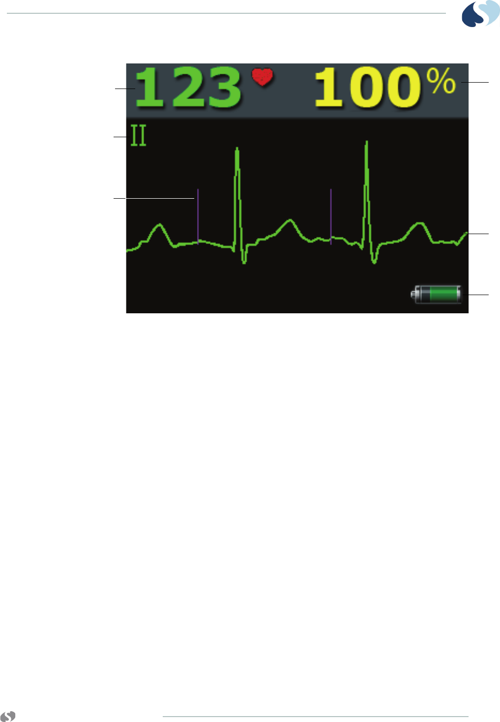
www.spacelabshealthcare.com 4-13
TELEMETRY TRANSMITTER (96281) BASIC OPERATIONS
Figure 4-6 Paced ECG and SpO2 display on the 96281-C
1 SpO2 saturation percentage (available on 96281-C only)
2 ECG waveform
3 Battery charge indicator (shows the battery state)
4 Pacing marker
5 Shown lead indicator
6 Heart rate derived from ECG (indicated by solid
heart icon)
Notes:
The AriaTele acquires and transmits ECG data in samples. In
addition, it may show the ECG waveform on its optional display.
When the AriaTele acquires an ECG sample that it detects as
possessing a pacing pulse, it does two things:
• It sends a notification to the receiving system, indicating that
the ECG sample contained a pacing pulse.
• It marks the location of the pacing pulse, on its optional
display, using purple pacing markers as shown.
The receiver system uses the information it receives to mark
corresponding purple pacing pulses on the ECG waveform that it
receives.
Notes:
• ECG leads show in the order that follows: Lead II, V, Lead I,
Lead III.
• If a lead is not available due to electrode configuration, that
lead shows as a blank waveform on the display.
1
2
3
5
6
4
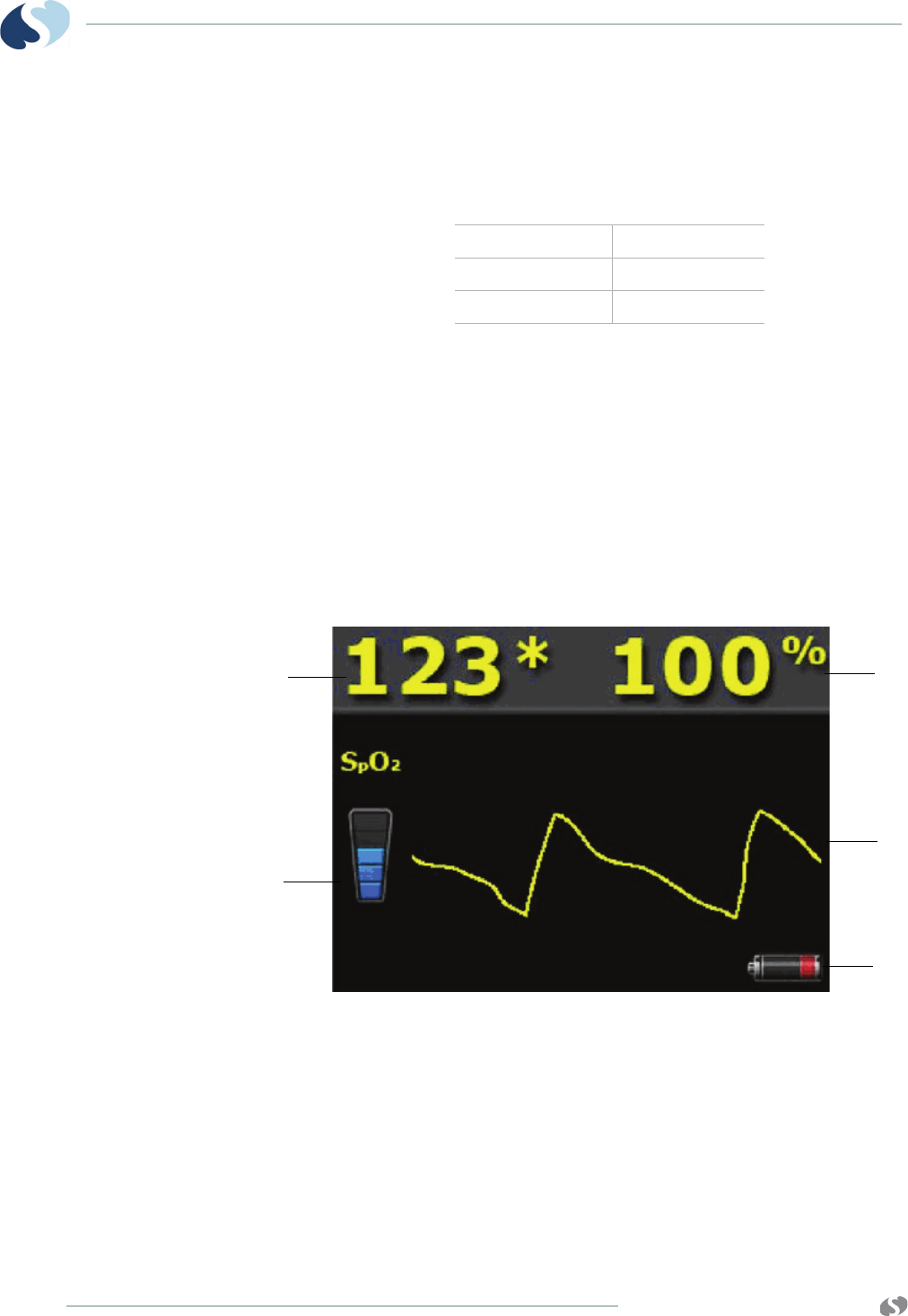
www.spacelabshealthcare.com
4-14
TELEMETRY TRANSMITTER (96281) BASIC OPERATIONS
• Pacing marker (shows only if detected) is shown as a vertical
purple line.
The symbols that follow show on the 96281-B and 96281-C telemetry
transmitter LCD when numerics are not available or are out of the
designated range for a parameter.
SpO2
SpO2 is only available with the 96281-C. SpO2 data is obtained
directly from the patient and may show as in Figure 4-7, depending
on configuration of leads and available parameters.
The 96281-C auto-detects a sensor connection and activates or
deactivates the SpO2 option accordingly.
Note:
SpO2 view does not show if a SpO2 adapter cable is not
connected.
Figure 4-7 Typical SpO2 display on 96281-C (shows a low battery
state)
1 SpO2 saturation percentage (96281-C only)
2 SpO2 pulse waveform (96281-C only)
3 Battery charge indicator (defined by quartiles)
4 Signal quality/strength indicator (at least one color bar in
the indicator is recommended for a reliable SpO2 value)
5 Pulse rate derived from SpO2 (indicated by an asterisk)
Not available ???
Under range - - -
Over range +++
4
1
2
5
3

www.spacelabshealthcare.com 4-15
TELEMETRY TRANSMITTER (96281) BASIC OPERATIONS
Status Messages at the Host Monitor
Various status messages related to the telemetry transmitter may
show at the host monitor when there is a problem with the signal or
when the battery is low. The host monitor may be either the central
station or bedside monitor.
The status messages that follow may appear at the host monitor.
Refer to SpO2 Messages at the Host Monitor on page 3-18, for status
messages related to SpO2.
• INTERMITTENT SIGNAL LOSS
Indicates that the patient may be out of antenna range or the
battery is depleted. Return the patient into antenna range. Check
that the battery is functioning properly. A low-priority alarm
occurs after 10 seconds in this condition.
• LOW BATTERY
Indicates the battery is weak. After this message appears, the
battery has approximately one hour of useful life left (depending
on the type of battery used). Install a new battery. A low-priority
alarm occurs if the setup menu’s LOW BAT ON/OFF key is set to
ON.
• SIGNAL INTERFERENCE
Indicates, through the triangle-shaped squelch waveform, that
an interfering signal has been detected. The patient’s signal can
no longer be detected because of interference from a stronger
signal source lasting more than 0.5 seconds. A low priority alarm
occurs whenever this message appears in the waveform zone.
• IS SIGNAL LOSS PERMANENT?
Indicates no radio frequency (RF) signal is detected.
•Do not ignore status messages.
•SpO2 data may not show when the INTERMITTENT SIGNAL
LOSS message appears.
•Status messages indicate a problem or condition which
may affect accurate monitoring values.
•Correct any fault before continuing.

www.spacelabshealthcare.com
4-16
TELEMETRY TRANSMITTER (96281) BASIC OPERATIONS
Telemetry Transmitter with ECG Only
Troubleshooting Guide
Telemetry Transmitter with Display
Troubleshooting Guide
Clinical Situation Possible Cause Solution
Low battery LED
flashing
• The batteries are low. • Replace batteries.
All leads off LEDs lit • Self test failure. • Contact Spacelabs
Healthcare.
Any or all leads off
LEDs flashing
•Check ECG leads.
ECG is not shown at
Central Station
• Check if batteries are low. • Replace batteries.
ECG is not shown at
Central Station
• Unit malfunction. • Contact Spacelabs
Healthcare.
Clinical Situation Possible Cause Solution
Low battery LED
flashing
• The batteries are low. • Replace batteries.
All leads off LEDs lit • Self test failure. • Contact Spacelabs
Healthcare.
Any or all leads off
LEDs flashing
•Check ECG leads.
ECG is not shown at
Central Station
• Check if batteries are low. • Replace batteries.
ECG is not shown on
transmitter display
• Unit malfunction. • Contact Spacelabs
Healthcare.

www.spacelabshealthcare.com 4-17
TELEMETRY TRANSMITTER (96281) BASIC OPERATIONS
Telemetry Transmitter with Display and SpO2
Troubleshooting Guide
Clinical Situation Possible Cause Solution
Low battery LED
flashing
• The batteries are low. • Replace batteries.
All leads off LEDs lit • Self test failure. • Contact Spacelabs
Healthcare.
Any or all leads off
LEDs flashing
•Check ECG leads.
ECG is not shown at
Central Station
• Check if batteries are low. • Replace batteries.
SpO2 data is not
shown on transmitter
display
•SpO
2 cable and/or sensor is
faulty.
• Unit malfunction.
•Check SpO
2 cable and
sensor.
• Contact Spacelabs
Healthcare.
SpO2 is not shown at
Central Station
• Unit malfunction. • Contact Spacelabs
Healthcare.

www.spacelabshealthcare.com
4-18
TELEMETRY TRANSMITTER (96281) BASIC OPERATIONS
www.spacelabshealthcare.com 5-1
TELEMETRY TRANSMITTER (96281)
Cleaning, Disinfecting,
and Sterilization
Cleaning Products Not Recommended for Use
Cleaning the Display
Clean the display with a soft cloth moistened with either
70% isopropyl alcohol solution or soapy water.
Notes:
Obey your hospital protocol for the handling of blood and body
fluids.
• Do not use Accelerated Hydrogen Peroxide (AHP) and
quaternary ammonia-based products to clean the
transmitter, leadwires, cables, or sensors. Common
quaternary ammonia germicidal products include
Cavicide, Virex, Virex 256, SaniCloth, and Sanicloth Plus.
• These chemicals attack the plastics used in patient
monitors and cables, and will cause serious safety hazards
as the electrical insulating properties and structural
integrity of the equipment break down.
• These germicidal products are safe for use ONLY on hard,
non-porous surfaces, such as linoleum floors, formica
countertops, and stainless steel.
www.spacelabshealthcare.com
5-2
TELEMETRY TRANSMITTER (96281) CLEANING, DISINFECTING,
AND STERILIZATION
Transmitter, Leadwires, Cables, and Sensors
Cleaning/Disinfecting
Recommended Cleaning Solutions
Use only the recommended cleaning solutions that follow:
• Mild soap and water solution
• U.S. Pharmacopoeia (USP) green soap
• Sodium hypochlorite solution (1:10 dilution of household
chlorine bleach in water)
• Phenolic germicidal detergent (1% aqueous solution)
• Isopropyl alcohol (70% solution)
Note:
• Repeated use of a chlorine bleach solution may cause some
colors to fade.
• Tape adhesive can be removed with Spacelabs Healthcare
adhesive tape remover pads (P/N 392196-001).
Accessories
• Where provided, obey the manufacturers' instructions
concerning disposable and reusable supplies.
• Use only recommended cleaning solutions, or you may
void the manufacturer’s warranty.
• Harsh chemical agents degrade plastics and compromise
the safety of the device. Some germicidal and other harsh
cleaning compounds are known to damage some plastics
by weakening the structural integrity and compromising
the electrical insulating properties.
• Disconnect the equipment from the patient before
cleaning.
• Do not immerse the equipment or cables in water or
cleaning solutions.
• Do not autoclave.
Questions and concerns about cleaning issues should be
directed to Spacelabs Healthcare Technical Support.

www.spacelabshealthcare.com 5-3
TELEMETRY TRANSMITTER (96281) CLEANING, DISINFECTING,
AND STERILIZATION
• As applicable, obey your hospital protocol concerning
cleaning, disinfection, and/or sterilization of reusable
supplies.
• Obey hospital protocols to dispose of used and
contaminated single-use accessories.
Cleaning and Disinfecting the 96281Telemetry
Transmitters and Cables
In normal use the product is worn by one hospital patient for a few
days. Clean and disinfect the transmitter after every procedure and/
or before it is worn by another patient. There is a risk that the
product may carry dangerous levels of infectious agents to the next
patient if it is not adequately cleaned and/or disinfected.
Refer to Recommended Cleaning Solutions on page 5-2 for a list of
acceptable cleaning solutions.
Basic Cleaning and Low-level Disinfection
1Remove the batteries and close the battery cover.
2Remove the ECG leadwires, grouper, and SPO2 cable (if fitted).
3Inspect the transmitter for contamination. If required and carry
out steps 4 and 5 to clean the transmitter.
4Rub the transmitter with a cloth wetted in a mild detergent
solution.
5Dry the transmitter thoroughly.
6Prepare the cleaning solution chosen from the list of
recommended cleaning solutions according to the
manufacturer’s instructions.
7Wet a clean cloth with the selected cleaning solution.
8Remove excess liquid from the cloth and squeeze dry.
9Wipe all exposed surfaces of the equipment and cables.
10 Leave the transmitter for the required contact time, during which
it should remain wet.
11 Remove any soap residue by gently wiping with a clean damp
cloth.
12 Wipe dry with a clean dry cloth.
13 Take steps to remove disinfectant residues in accordance with
the disinfectant labelling.

www.spacelabshealthcare.com
5-4
TELEMETRY TRANSMITTER (96281) CLEANING, DISINFECTING,
AND STERILIZATION
Cleaning ECG Leadwires
Inspect the leadwire sockets for contamination. If necessary, flush
using a syringe and clean using a toothpick. Once clean, Spacelabs
Healthcare recommends wetting the sockets with 70% isopropyl
alcohol to provide low level disinfection. This agent can be left to
dry naturally and does not require any rinse procedures.
Note:
After cleaning ECG leadwires, remove the ECG leadwires from
the lead block and thoroughly dry them at the lead block ends
and at the lead connector ends. Thorough drying will prevent
residual moisture from providing a low-current path between
leads, which can interfere with lead off detection and cause false
asystoles.
Cleaning Buttons
Clean the buttons by wetting a small brush with a mild detergent
solution and gently scrubbing around and across the buttons. Dry
the buttons with a rubbing action.
Disinfect the buttons by using the same method. Spacelabs
Healthcare recommends using 70% isopropyl alcohol which can be
left to dry naturally and does not require any rinse procedures.
Cleaning the Battery Cover
Clean around the battery cover release with a small brush using a
mild detergent solution. Disinfect using the same method with 70%
isopropyl alcohol to provide low level disinfection.
Open the battery cover and inspect the hinges and catch for
contamination. If necessary, flush using a syringe and clean using a
small brush, taking care not to deform the cover spring. Once clean,
we recommend wetting with 70% isopropyl alcohol to provide low
level disinfection. This agent can be left to dry naturally and does
not require any rinse procedures.

www.spacelabshealthcare.com A-1
TELEMETRY TRANSMITTER (96281)
Appendix A — Guidance and
Manufacturer’s Declaration
Electromagnetic Environment
The 96281 telemetry transmitter is intended for use in the
electromagnetic environment specified in the reference tables in this
chapter. The customer or user of the 96281 should make sure that it
is used in such an environment.
Electromagnetic Emmissions
Table A-1 Electromagnetic Emmissions
Emission Test Compliance Electromagnetic Environment
RF emissions
CISPR 11 Group 1 The 96281 emits electromagnetic energy in
order to perform its intended function. Nearby
electronic equipment may be affected.
RF emissions
CISPR 11 Class B The 96281 is suitable for use in all
establishments, including those directly
connected to the public low-voltage power
supply network that supplies public buildings.
Harmonic emissions
IEC 61000-3-2 N/A N/A
Voltage fluctuations/
flicker emissions
IEC 61000-3-3
N/A N/A

www.spacelabshealthcare.com
A-2
TELEMETRY TRANSMITTER (96281) APPENDIX A — GUIDANCE AND
MANUFACTURER’S DECLARATION
Electromagnetic Immunity
Table A-2 Electromagnetic Immunity
Immunity Test IEC 60601 Test Level Compliance
Level
Electromagnetic
Environment
Electrostatic
discharge (ESD)
IEC 61000-4-2
±6 kV contact
±8 kV air
±6 kV contact
±8 kV air
Floors should be wood,
concrete, or ceramic tile.
If floors are covered with
synthetic material, the
relative humidity should
be at least 30%.
Electrical fast
transient/burst
IEC 61000-4-4
±2 kV for power supply lines
±1 kV for input/output lines
N/A N/A
Surge
IEC 61000-4-5
±1 kV line(s) to line(s)
±2 kV line(s) to earth
N/A N/A
Voltage dips, short
interruptions, and
voltage variations
on power supply
input lines
IEC 61000-4-11
<5% UT
(>95% dip in UT for 0.5 cycle)
40% UT
(60% dip in UT for 5 cycles)
70% UT
(30% dip in UT for 25 cycles)
<5% UT
(>95% dip in UT for 5 seconds)
N/A N/A
Power frequency
(50/60 Hz)
magnetic field
IEC 61000-4-8
3 A/m 3 A/m Power frequency
magnetic fields should be
at levels characteristic of
a typical location in a
commercial or hospital
environment.
Note:
UT is the AC mains voltage prior to application of the test level.
Conducted RF
IEC 61000-4-6
N/A N/A Portable and mobile
RF communications
equipment should be
used no closer to any
part of the monitoring
device, including
cables, than the
recommended
separation distance
calculated from the
equation applicable to
the frequency of the
transmitter.
Radiated RF
IEC 61000-4-3
3V/m
80 MHz to 2.5 GHz
3V/m
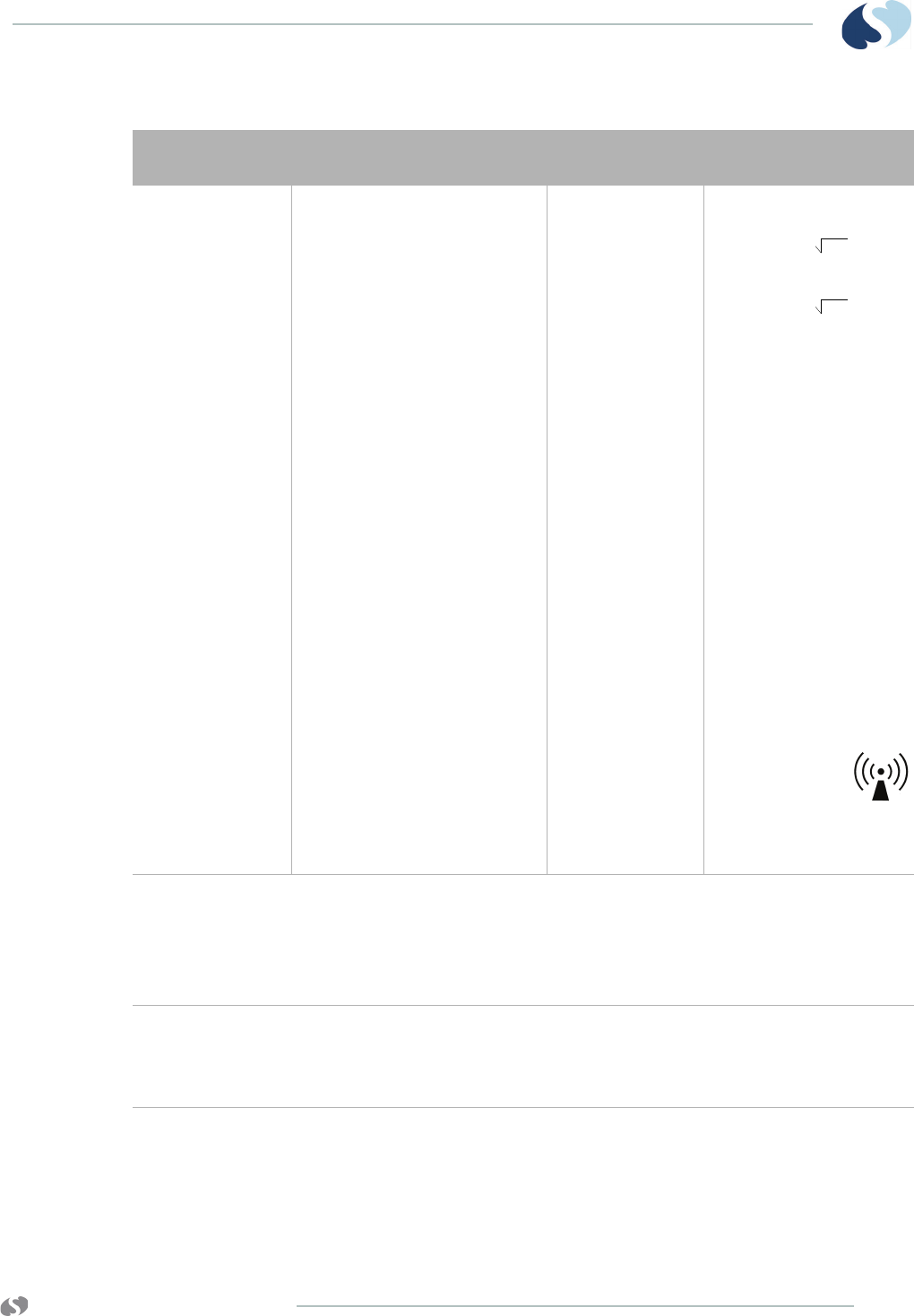
www.spacelabshealthcare.com A-3
TELEMETRY TRANSMITTER (96281) APPENDIX A — GUIDANCE AND
MANUFACTURER’S DECLARATION
Recommended
separation distance:
Where P is the
maximum output
power rating of the
transmitter in watts
(W), according to the
transmitter
manufacturer, and d is
the recommended
separation distance in
meters (m).
Field strengths from
fixed RF transmitters,
as determined by an
electromagnetic site
survey (a), should be
less than the
compliance level in
each frequency range.
Interference
may occur in the
vicinity of
equipment marked
with the following
symbol.
* Field strengths from fixed transmitters, such as base stations for radio (cellular/cordless) telephones and
land mobile radios, amateur radio, AM and FM radio broadcast, and TV broadcast cannot be predicted
theoretically with accuracy. To assess the electromagnetic environment due to fixed RF transmitters, an
electromagnetic site survey should be considered. If the measured field strength in the location in which
the monitoring device are used exceeds the applicable RF compliance level above, the 96281 telemetry
device should be observed to verify normal operation. If abnormal performance is observed, additional
measures may be necessary, such as reorienting or relocating the 96281 telemetry device.
Notes:
• At 800 MHz, the higher frequency range applies.
• These guidelines may not apply in all situations. Electromagnetic propagation is
affected by absorption and reflection from structures, objects, and people.
Table A-2 Electromagnetic Immunity
Immunity Test IEC 60601 Test Level Compliance
Level
Electromagnetic
Environment
d = 1.17 P
80 MHz to 800 MHz
d = 2.34 P
800 MHz to 2.5 GHz

www.spacelabshealthcare.com
A-4
TELEMETRY TRANSMITTER (96281) APPENDIX A — GUIDANCE AND
MANUFACTURER’S DECLARATION
Separation Distances
The 96281 is intended for use in an electromagnetic environment in
which radiated RF disturbances are controlled. The customer or user
of the 96281 telemetry transmitter can help prevent electromagnetic
interference by maintaining a minimum distance between portable
and mobile RF communications equipment (transmitters) and the
96281 as recommended below, according to the maximum output
power of the communications equipment.
Table A-3 Separation Distances
Recommended separation distances between portable and
mobile RF communications and the 96281 telemetry transmitter
Rated maximum output
power of Transmitter (W)
Separation distance according to
the frequency of transmitter (m)
0.01 0.117 0.234
0.1 0.37 0.738
11.172.34
10 3.69 7.37
100 11.7 23.4
For transmitters rated at a maximum output power not listed above, the recommended
separation distance d in meters (m) can be estimated using the equation applicable to the
frequency of the transmitter, where P is the maximum output power rating of the
transmitter in watts (W) according to the transmitter manufacturer.
Notes:
• At 80 MHz and 800 MHz, the separation distance for the higher frequency range
applies.
• These guidelines may not apply in all situations. Electromagnetic propagation is
affected by absorption and reflection from structures, objects, and people.
d = 1.17 P
80 MHz to 800 MH
d = 2.34 P
800 MHz to 2.5 GH

www.spacelabshealthcare.com A-5
TELEMETRY TRANSMITTER (96281) APPENDIX A — GUIDANCE AND
MANUFACTURER’S DECLARATION
Notes on ECG Leads
•DC means direct current
•RA means right arm
•RL means right leg
•RMS means root mean squared
•AC means alternating current
Lead Off Detection Currents Leads off detection uses a DC lead off current of 12 nA for RA
and 27 nA for the all the other electrodes except RL.
Right leg electrode depends on the number of electrodes
connected, but has a DC current of typically 71 nA rising to 83 nA
in the worst case lead configuration.
Active Right Leg Drive Current The AriaTele transmitter has an active right leg circuit. The
maximum right leg drive noise cancellation current is limited
to <4.8 uA RMS AC and <9.5 uA DC, and a maximum voltage of
1.5 V RMS AC.

www.spacelabshealthcare.com
A-6
TELEMETRY TRANSMITTER (96281) APPENDIX A — GUIDANCE AND
MANUFACTURER’S DECLARATION

www.spacelabshealthcare.com B-1
TELEMETRY TRANSMITTER (96281)
Appendix B — Symbols
The following list of international and safety symbols describes all
symbols used on Spacelabs Healthcare products. No one product
contains every symbol.
Note:
Graphic elements of certain keys and symbols may vary between
product lines.
HELP Key
HELP (Explain Prior Screen) Key
MONITOR SETUP Key
REMOTE Key
TRENDS Key
?
www.spacelabshealthcare.com
B-2
TELEMETRY TRANSMITTER (96281) APPENDIX B — SYMBOLS
RECORD Key
Dynamic Network Access (DNA) Key
SPECIAL FUNCTIONS Key
NORMAL SCREEN Key
SAVE Key
No Network Connection
Network Connection
Do Not Connect to Network
No Connection to Intesys® Clinical Suite (ICS)
Compression
Magnifying Glass
File Cabinet
List of Rooms
Printer
Service Message
www.spacelabshealthcare.com B-3
TELEMETRY TRANSMITTER (96281) APPENDIX B — SYMBOLS
PREVIOUS MENU Key
HOME Key
Arrows
On Direction
ON — Power Connection to Mains
ON — Part of the Instrument Only
ON Position for Push Button Power Switch
OFF — Power Disconnection from Mains
OFF Position for Push Button Power Switch
OFF — Part of the Instrument Only
Partial ON/OFF
ON/OFF
Standby
STANDBY Key
Power ON/OFF Key
Keyboard Connection
www.spacelabshealthcare.com
B-4
TELEMETRY TRANSMITTER (96281) APPENDIX B — SYMBOLS
Mouse Connection
PAUSE or INTERRUPT
START/STOP Key
START/STOP
STOP or CANCEL Key
CONTINUE Key
ENTER Key
Delete
Nurse Alert Interface
ALARM SUSPEND/TONE RESET Key
ALARMS Key
Alarm, General
Alarm Reset
Alarm Audio ON
Alarm Audio OFF
Alarm Audio Paused
x
www.spacelabshealthcare.com B-5
TELEMETRY TRANSMITTER (96281) APPENDIX B — SYMBOLS
Low Priority Alarm
Medium Priority Alarm
High Priority Alarm
Alarms Paused
Alarm OFF
Parameter below measurement range
Parameter above measurement range
Parameter measurement indeterminate
Indicator — Remote Control
PRINT REPORT Key
Normal Screen
Clock/Time Setting Key
Slow Run
Activate Recorder for Graphics
Reset
---
+++
???

www.spacelabshealthcare.com
B-6
TELEMETRY TRANSMITTER (96281) APPENDIX B — SYMBOLS
START (NIBP) Key
Power Indicator LED
Activate Telemetry Recorder
Output (Non-terminated)
Data Input/Output
Input
No Output (Terminated)
Indicator — Local Control
Indicator — Out of Paper
Recorder Paper
Menu Keys
Waveform/Parameter Keys
Return to Prior Menu
Monitor Setup
Select Program Options
Set Initial Conditions Menu
1
2
31
2
3
1
2
3
1
2
3
A

www.spacelabshealthcare.com B-7
TELEMETRY TRANSMITTER (96281) APPENDIX B — SYMBOLS
Access Special Function Menu
Return Unit to Monitor Mode
Keypad
Serial Port 1
Serial Port 2
Serial Port
Auto Mode (NIBP)
External Marker Push Button Connection
Arterial Pulse
Gas Exhaust
Video Output
Television; Video Display
Video Output, Primary
Video Output, Secondary
Enlarge, Zoom
1
2
3
B
1
2
3
1
2
www.spacelabshealthcare.com
B-8
TELEMETRY TRANSMITTER (96281) APPENDIX B — SYMBOLS
Input/Output
PCMCIA Card
Touchscreen, External
Universal Serial Bus
SDLC Port
Hard Drive
Antenna
Electrocardiograph or
Defibrillator Synchronization
Microphone
Foot Switch
Audio Output, Speaker
Event
Gas Sampling Port
Gas Return Port
Battery
Replace only with the appropriate battery.
SDLC
www.spacelabshealthcare.com B-9
TELEMETRY TRANSMITTER (96281) APPENDIX B — SYMBOLS
Battery Status
Battery
Replace only with the appropriate battery.
Low Battery
Replace only with the appropriate battery.
(+ / - signs may be reversed)
All batteries should be disposed of properly to protect the environment. Lithium batteries
should be fully discharged before disposal. Batteries such as lead-acid (Pb) and nickel-
cadmium (Ni-Cd) must be recycled. Please follow your internal procedures and or local
(provincial) laws regarding disposal or recycling.
This symbol indicates that the waste of electrical and electronic equipment must not be
disposed as unsorted municipal waste and must be collected separately. Please contact
an authorized representative of the manufacturer for information concerning the
decommissioning of your equipment.
Caution - hazardous voltages. To reduce risk of electric shock, do not remove the cover or
back. Refer servicing to a qualified field service engineer (U.S.A.).
DANGER - High Voltage (International)
Protective Earth Ground
Replace Fuse Only as Marked
Power supply jack polarity.
(+ / - signs may be reversed)
Alternating Current
Both Direct and Alternating Current
Functional Earth Ground
Fuse
Equipotentiality Terminal
www.spacelabshealthcare.com
B-10
TELEMETRY TRANSMITTER (96281) APPENDIX B — SYMBOLS
Direct Current
Input Power. Use only Spacelabs Power Supply (P/N 119-0527-xx).
AC/DC Input
Loop Filter
Audio Output, Speaker
IEC 60601-1 Type B equipment. The unit displaying this symbol contains an adequate
degree of protection against electric shock.
IEC 60601-1 Type BF equipment which is defibrillator-proof. The unit displaying this
symbol is an F-type isolated (floating) patient-applied part which contains an adequate
degree of protection against electric shock, and is defibrillator-proof.
IEC 60601-1 Type BF equipment. The unit displaying this symbol is an F-type isolated
(floating) patient-applied part providing an adequate degree of protection against electric
shock.
IEC 60601-1 Type CF equipment. The unit displaying this symbol is an F-type isolated
(floating) patient-applied part providing a high degree of protection against electric shock,
and is defibrillator-proof.
IEC 60601-1 Type CF equipment. The unit displaying this symbol is an F-type isolated
(floating) patient-applied part providing a high degree of protection against electric shock.
IEC 60601-1 Class II equipment, double-isolated. The unit displaying this symbol does
not require a grounded outlet.
Warning: Do not modify this equipment without authorization of the manufacturer.
Operates on Non-Harmonized Radio Frequencies in Europe
Adult Noninvasive Blood Pressure (NIBP)
Fetal Monitor Connection (Analog)
!

www.spacelabshealthcare.com B-11
TELEMETRY TRANSMITTER (96281) APPENDIX B — SYMBOLS
Fetal Monitor Connection
RS-232 (Digital)
Physiological Monitor Connection RS-232 (Digital)
Noninvasive Blood Pressure (NIBP), Neonate
Symbol Set, Adult/Pediatric Cuff Sizes
Symbol Set, Neonatal Cuff Sizes
NIBP Cuff, Neonatal 1
NIBP Cuff, Neonatal 2
NIBP Cuff, Neonatal 3
NIBP Cuff, Neonatal 4
NIBP Cuff, Neonatal 5
NIBP Cuff, Single Hose
NIBP Cuff, Dual Hose
NIBP Cuff, Surface Applied to Patient
THIS SIDE TO PATIENT

www.spacelabshealthcare.com
B-12
TELEMETRY TRANSMITTER (96281) APPENDIX B — SYMBOLS
NIBP Cuff, Child Size
(12 to 19 cm)
NIBP Cuff, Child Size, Long
(12 to 19 cm)
NIBP Cuff, Small Adult Size, Long
(17 to 25 cm)
NIBP Cuff, Small Adult Size
(17 to 25 cm)
NIBP Cuff, Adult Size, Long
(23 to 33 cm)
NIBP Cuff, Large Adult Size, Long
(31 to 40 cm)
NIBP Cuff, Large Adult Size
(31 to 40 cm)
NIBP Cuff, Adult Size
(23 to 33 cm)
NIBP Cuff, Infant Size
(8 to 13 cm)
NIBP Cuff, Neonatal 1 Size
(3 to 6 cm)
NIBP Cuff, Neonatal 2 Size
(4 to 8 cm)
NIBP Cuff, Neonatal 3 Size
(6 to 11 cm)
NIBP Cuff, Neonatal 4 Size
(7 to 13 cm)
NIBP Cuff, Neonatal 5 Size
(8 to 15 cm)
NIBP Cuff, Thigh Size (38-50 cm)
CHILD
CHILD, LONG
SMALL ADULT, LONG
SMALL ADULT
ADULT, LONG
LARGE ADULT, LONG
LARGE ADULT
ADULT
INFANT
NEONATAL 1
NEONATAL 2
NEONATAL 3
NEONATAL 4
NEONATAL 5
THIGH
www.spacelabshealthcare.com B-13
TELEMETRY TRANSMITTER (96281) APPENDIX B — SYMBOLS
NIBP Cuff, Nylon Material
NIBP Cuff, Soft Material
NIBP Cuff, Vinyl Material
Quantity
Place Artery Symbol and Arrow over Brachial or Femoral Artery
eIFU = electronic Instructions for Use (CD-ROM or website) is available
Consult Instructions For Use
Follow Instructions For Use
Warning About Potential Danger to Human Beings (Consult Accompanying Documents)
Caution About Potential Danger to a Device (Consult Accompanying Documents)
Note Note
Keep Dry
NYLON
SOFT
VINYL
QTY
ARTERY
e
I
F
U
I
n
d
i
c
a
t
o
r

www.spacelabshealthcare.com
B-14
TELEMETRY TRANSMITTER (96281) APPENDIX B — SYMBOLS
Indoor Use Only
Environmental Shipping/Storage Altitude Limitations
Environmental Shipping/Storage Temperature Limitations
Fragile
Handle with Care
This Way Up
Up Arrow
Down Arrow
Environmental Shipping/Storage Humidity Limitations
Humidity limitation
Atmospheric pressure limitation
Open Padlock
Closed Padlock
Happy Face
Sad Face
12,200 m
95%
www.spacelabshealthcare.com B-15
TELEMETRY TRANSMITTER (96281) APPENDIX B — SYMBOLS
PVC-Free (Polyvinyl Chloride)
Do Not Reuse; Single Use Only
Reusable
IPX1 Drip-Proof
IPX7 Unit can withstand accidental immersion in one meter of water for up to 30 minutes
Reference Number or Order Number
Use by date [YYYY-MM-DD]
Recycle
Non Sterile
Latex-Free
Date of Manufacture
Manufacturer
Radio transmitting device; elevated levels of non-ionizing radiation
A CE mark certifies that a product has met EU health, safety, and environmental
requirements, which ensure consumer safety.
PVC
2
REF

www.spacelabshealthcare.com
B-16
TELEMETRY TRANSMITTER (96281) APPENDIX B — SYMBOLS
ABBREVIATIONS USED AS SYMBOLS
XXXX is the European Notified Body number. 0123 is the number for TÜV SÜD Product
Service GmbH, München, Germany.
Canadian Standards Association Approved
Batch Code
Nellcor Oxisensor II Compatible
Novametrix Compatible
Spacelabs TruLink Compatible
Nellcor OxiMax Compatible
Spacelabs Compatible
UL recognized component in Canada and United States
Nellcor OxiMax Compatible
Masimo SET Compatible
XXXX
®
C
U
LOT
NE
2
NV
X
R
1 - 32 Access Codes 1 Through 32
AIR Air
Amperes
ANT 1
ANT 2
Diversity Antenna System 1
Diversity Antenna System 2
A

www.spacelabshealthcare.com B-17
TELEMETRY TRANSMITTER (96281) APPENDIX B — SYMBOLS
Arr1
ArrNet2
Arrhythmia Net 1
Arrhythmia Net 2
avDO2Arterial/Venous Oxygen Difference
CaO2Arterial Oxygen
CH
ch
EEG, EMG, or ECG Channel
EEG Channels - CH1, CH2, CH3, CH4
EMG Channel - CH5
cmH2OCentimeters of Water
C.O.
CO Cardiac Output
CvO2Venous Oxygen
CO2
CO2
Carbon Dioxide
DIA
dia Diastolic
ECG
ecg Electrocardiogram
EEG
eeg Electroencephalogram
EMG
emg Electromyogram
ESIS Electrosurgical Interference Suppression
EXT External
FECG Fetal Electrocardiogram
FHR1
FHR2
Fetal Heart Rate, Channel 1
Fetal Heart Rate, Channel 2
GND
gnd Ground
Hertz
Hgb Hemoglobin
HLO
hlo High-Level Output
Multiview Multi-Lead Electrocardiogram
N2ONitrous Oxide
NIBP
nibp Noninvasive Blood Pressure
O2AV Oxygen Availability
O2Oxygen
Hz

www.spacelabshealthcare.com
B-18
TELEMETRY TRANSMITTER (96281) APPENDIX B — SYMBOLS
PaO2Partial Pressure of Arterial Oxygen
PRESS
press
PRS
Pressure
PvO2Partial Pressure of Mixed Venous Oxygen
Oxygen reference gas port
RESP
resp Respiration
SDLC Synchronous Data Link Control
Serial number
SPO2
SpO2
SpO2
SaO2
Arterial Oxygen Saturation
as Measured by Pulse Oximetry
SVO2
SvO2
SvO2
Mixed Venous Oxygen Saturation
SYS
sys Systolic
T1
T2
T3
T4
Temperature 1
Temperature 2
Temperature 3
Temperature 4
TEMP
temp Temperature
UA Uterine Activity or Umbilical Artery
UV Umbilical Venous
VAC Vacuum Connection
VO2Oxygen Consumption
Volts
Watts
Ref.
SN
V
W