Spacelabs Healthcare 76A90341-WMTS 90341-05 User Manual 1 of 3
Spacelabs Healthcare, Inc. 90341-05 1 of 3
Contents
- 1. User Manual 1 of 3
- 2. User Manual 2 of 3
- 3. User Manual 3 of 3
User Manual 1 of 3

Ultraview Care Network
Operations Manual
070-1001-17 Rev. A
®

Copyright 2003 Datex-Ohmeda, Inc.
All rights reserved. Contents of this publication may not be reproduced in any form without the written permission of Datex-Ohmeda,
Inc. Products of Spacelabs Medical, a Division of Instrumentarium, Datex-Ohmeda, Inc. (“Spacelabs Medical”) are covered by U.S.
and foreign patents and/or pending patents. Printed in U.S.A. Specifications and price change privileges are reserved.
Spacelabs Medical considers itself responsible for the effects on safety, reliability and performance of the equipment only if:
• assembly operations, re-adjustments, modifications or repairs are carried out by persons authorized by Spacelabs
Medical, and
• the electrical installation of the relevant room complies with the requirements of the standard in force, and
• the equipment is used in accordance with the operations manual.
Spacelabs Medical will make available, on request, such circuit diagrams, component part lists, descriptions, calibration instructions
or other information which will assist appropriately qualified technical personnel to repair those parts of the equipment which are
classified by Spacelabs Medical as field repairable.
Spacelabs Medical is committed to providing comprehensive customer support beginning with your initial inquiry through purchase,
training, and service for the life of your Spacelabs Medical equipment.
U.S.A.
Spacelabs Medical
5150 220th Ave SE
Issaquah, WA 98029
Telephone: 425-657-7200
Telephone: 800-345-2700
Fax: 425-657-7212
AUSTRALIA
Datex-Ohmeda Pty Ltd
Unit 1, 149 Arthur Street
Locked Bag 356
Homebush, NSW 2140
Telephone: 61-2-9735-7222
Fax: 61-2-9764-2354
AUSTRIA & BELGIUM
Meda n.v.
Oeyvaersbosch 12
B-2630 Aartselaar
Belgium
Telephone: 32-3-870-1111
Fax: 32-3-870-1112
CANADA
Datex-Ohmeda Inc.
1093 Meyerside Drive, Unit 2
Mississauga, Ontario L5T 1J6
Telephone: 905-565-8572
Fax: 905-565-8592
CORPORATE OFFICES
CHINA
Datex-Ohmeda Pte Ltd
Shanghai Representative Office
Room 2509 Lippo Plaza
No. 222 Huaihai Road (M)
Shanghai 200021
Telephone: 86-21-5382-5657
Fax: 86-21-5382-1691
FRANCE
Spacelabs Medical
ZAC de Sans-Souci
1211 Chemin de la Bruyére
69760 Limonest
Telephone: 33 4 78 666 210
Fax: 33 4 78 432 658
GERMANY
Datex-Ohmeda GmbH
Dr. -Alfred-Herrhausen-Allee 24
D-47228 Duisburg
Telephone: 49-2065-691-0
Fax: 49-2065-691-236
INDIA
Datex-Ohmeda India Pvt. Ltd.
International Trade Tower
S 3 Level, Block E
Nehru Place
New Delhi 110019
Telephone: 91-11-621-6060
Fax: 91-11-621-3003
ITALY
Datex-Ohmeda S.p.A.
Via Cassanese, 100
20090 Segrate (MI)
Telephone: 39-02-216-931
Fax: 39-02-2692-6226
SPAIN
Datex-Ohmeda SL
Manuel Tovar, 26
28034 Madrid
Telephone: 34-91-3342600
Fax: 34-91-3581284
TAIWAN
Datex-Ohmeda Pte Ltd
Taiwan Representative Office
2/FI No. 85 Sec. 2
Chien-Kuo N. RD.
Telephone: 8862-2515-0457
Fax: 8862-2501-9136
THE NETHERLANDS
Datex-Ohmeda B.V.
De Wel 18 3871 MV
Hoevelaken
Telephone: 31-33-25-41-222
Fax: 31-33-25-41-223
Authorized EC Representative
UNITED KINGDOM
Datex-Ohmeda Ltd
71 Great North Road, Hatfield
Herts AL9 5EN
Telephone: 44-1707-263-570
Fax: 44-1707-260-065
C
AUTI
O
N:
• US Federal law restricts the devices documented herein to sale by, or on the order of, a
physician.

About This Manual
Ultraview® Care Network Operations Manual documents a complete range of
patient monitoring functions for critical care. While each module may monitor one
or more vital sign parameters, the operation of individual parameters stays the
same throughout the system. This CD-ROM manual is organized by operating
functions rather than by specific products. Monitor and parameter functions are
presented in the CD-ROM titled Ultraview Care Network Operations Manuals
(P/N 084-0701-xx).
Quick Information At the beginning of each chapter you will find illustrations of the monitor keys that
appear on all Ultraview monitors.
Brief troubleshooting information for each function is found at the end of each
chapter. Troubleshooting tips suggest solutions to the most frequent problems.
Operating Instructions Each vital sign chapter contains a clinical overview, a description of the screen
display, operating instructions, error messages, and other pertinent information.
Product Compatibility
If your system does not contain a feature described in this manual:
• Your product may contain an earlier version of software. Refer to the original
documentation that accompanied your system.
• Your system configuration, including options ordered, may be different from
the configurations described in this manual. Refer to the notes in this manual
describing features likely to be impacted by system configuration.
Before moving a component from one network to another, be certain that the
component’s software version is compatible with that required by the second
network. If in doubt, have a qualified service person verify compatibility between
the component and the network.
Use only Spacelabs Medical parts and accessories with your Spacelabs Medical
components. Other parts may degrade performance or damage the components.
Refer to the Spacelabs Medical Supplies Products Catalog for the part numbers
and descriptions of additional parts and accessories.

i
Chapter Page
Contents
System Introduction and Network Basics
System Basics. . . . . . . . . . . . . . . . . . . . . . . . . . . . . . . . . . . . . . . . . . . . . . . . . . . . . . . . . . . . . 1-2
Monitor Basics. . . . . . . . . . . . . . . . . . . . . . . . . . . . . . . . . . . . . . . . . . . . . . . . . . . . . . . . . . . . . 1-3
Power Failure . . . . . . . . . . . . . . . . . . . . . . . . . . . . . . . . . . . . . . . . . . . . . . . . . . . . . . . . . . . . . 1-4
Network Basics . . . . . . . . . . . . . . . . . . . . . . . . . . . . . . . . . . . . . . . . . . . . . . . . . . . . . . . . . . . . 1-8
Watching Alarms Remotely - Alarm Watch . . . . . . . . . . . . . . . . . . . . . . . . . . . . . . . . . . . . . . . 1-9
Viewing Remote Parameters. . . . . . . . . . . . . . . . . . . . . . . . . . . . . . . . . . . . . . . . . . . . . . . . . . 1-9
Full Bed Review - UCW and Ultraview 1700 Only. . . . . . . . . . . . . . . . . . . . . . . . . . . . . . . . . 1-11
Reviewing Remote Trends . . . . . . . . . . . . . . . . . . . . . . . . . . . . . . . . . . . . . . . . . . . . . . . . . . 1-12
Alarms Directory
Directory of Keys . . . . . . . . . . . . . . . . . . . . . . . . . . . . . . . . . . . . . . . . . . . . . . . . . . . . . . . . . . . 2-1
Directory of Keys . . . . . . . . . . . . . . . . . . . . . . . . . . . . . . . . . . . . . . . . . . . . . . . . . . . . . . . . . . . 2-2
Alarms
Overview . . . . . . . . . . . . . . . . . . . . . . . . . . . . . . . . . . . . . . . . . . . . . . . . . . . . . . . . . . . . . . . . . 2-3
Default Alarm Limits . . . . . . . . . . . . . . . . . . . . . . . . . . . . . . . . . . . . . . . . . . . . . . . . . . . . . . . . 2-3
Setting Alarm Limits . . . . . . . . . . . . . . . . . . . . . . . . . . . . . . . . . . . . . . . . . . . . . . . . . . . . . . . . 2-4
Identifying Alarm Levels . . . . . . . . . . . . . . . . . . . . . . . . . . . . . . . . . . . . . . . . . . . . . . . . . . . . . 2-4
Adjusting Alarm Tones/Key Tones . . . . . . . . . . . . . . . . . . . . . . . . . . . . . . . . . . . . . . . . . . . . . 2-5
Controlling Alarms via the TONE RESET/ALM SUSPEND Key . . . . . . . . . . . . . . . . . . . . . . . 2-6
Alarm Watch . . . . . . . . . . . . . . . . . . . . . . . . . . . . . . . . . . . . . . . . . . . . . . . . . . . . . . . . . . . . . . 2-7
Automatic Recording of an Alarm . . . . . . . . . . . . . . . . . . . . . . . . . . . . . . . . . . . . . . . . . . . . . 2-10
Alarms Troubleshooting Guide . . . . . . . . . . . . . . . . . . . . . . . . . . . . . . . . . . . . . . . . . . . . . . . 2-11
Admit/Discharge Directory
Directory of Keys - Ultraview 1030/1050/1500/1600 . . . . . . . . . . . . . . . . . . . . . . . . . . . . . . . . 3-1
Directory of Keys - UCW and Ultraview 1700 . . . . . . . . . . . . . . . . . . . . . . . . . . . . . . . . . . . . . 3-2
Admit/Discharge
Overview . . . . . . . . . . . . . . . . . . . . . . . . . . . . . . . . . . . . . . . . . . . . . . . . . . . . . . . . . . . . . . . . . 3-3
Entering New Patient Information . . . . . . . . . . . . . . . . . . . . . . . . . . . . . . . . . . . . . . . . . . . . . . 3-4
Changing Patient Information . . . . . . . . . . . . . . . . . . . . . . . . . . . . . . . . . . . . . . . . . . . . . . . . . 3-9
Discharging a Patient . . . . . . . . . . . . . . . . . . . . . . . . . . . . . . . . . . . . . . . . . . . . . . . . . . . . . . . 3-9
Admit/Discharge Troubleshooting Guide. . . . . . . . . . . . . . . . . . . . . . . . . . . . . . . . . . . . . . . . 3-10
Printing Directory
Directory of Keys - Monitor Setup Level . . . . . . . . . . . . . . . . . . . . . . . . . . . . . . . . . . . . . . . . . 4-1
Directory of Keys - Biomed Level . . . . . . . . . . . . . . . . . . . . . . . . . . . . . . . . . . . . . . . . . . . . . . 4-2
Directory of Keys - Clinical Level. . . . . . . . . . . . . . . . . . . . . . . . . . . . . . . . . . . . . . . . . . . . . . . 4-3
Printing
Overview . . . . . . . . . . . . . . . . . . . . . . . . . . . . . . . . . . . . . . . . . . . . . . . . . . . . . . . . . . . . . . . . . 4-5
Bedside Printer Module . . . . . . . . . . . . . . . . . . . . . . . . . . . . . . . . . . . . . . . . . . . . . . . . . . . . . . 4-6
System Printer Module . . . . . . . . . . . . . . . . . . . . . . . . . . . . . . . . . . . . . . . . . . . . . . . . . . . . . . 4-6

Ultraview Care Network
ii
Ultraview 1030/1050 Monitor Printers. . . . . . . . . . . . . . . . . . . . . . . . . . . . . . . . . . . . . . . . . . . 4-7
PrintMaster . . . . . . . . . . . . . . . . . . . . . . . . . . . . . . . . . . . . . . . . . . . . . . . . . . . . . . . . . . . . . . . 4-7
Printing Priorities . . . . . . . . . . . . . . . . . . . . . . . . . . . . . . . . . . . . . . . . . . . . . . . . . . . . . . . . . 4-11
Selecting Print Duration . . . . . . . . . . . . . . . . . . . . . . . . . . . . . . . . . . . . . . . . . . . . . . . . . . . . 4-12
Printer Key Functions . . . . . . . . . . . . . . . . . . . . . . . . . . . . . . . . . . . . . . . . . . . . . . . . . . . . . . 4-13
Recording Alarms . . . . . . . . . . . . . . . . . . . . . . . . . . . . . . . . . . . . . . . . . . . . . . . . . . . . . . . . . 4-14
Selecting Recording Destination. . . . . . . . . . . . . . . . . . . . . . . . . . . . . . . . . . . . . . . . . . . . . . 4-14
Printing via Monitors . . . . . . . . . . . . . . . . . . . . . . . . . . . . . . . . . . . . . . . . . . . . . . . . . . . . . . . 4-14
Defining Preselected Recording Keys . . . . . . . . . . . . . . . . . . . . . . . . . . . . . . . . . . . . . . . . . 4-16
Loading Paper . . . . . . . . . . . . . . . . . . . . . . . . . . . . . . . . . . . . . . . . . . . . . . . . . . . . . . . . . . . 4-17
Paper Out Conditions . . . . . . . . . . . . . . . . . . . . . . . . . . . . . . . . . . . . . . . . . . . . . . . . . . . . . . 4-18
Record Vitals Report (Ultraview 1030/1050 Only) . . . . . . . . . . . . . . . . . . . . . . . . . . . . . . . . 4-19
Printing Troubleshooting Guide . . . . . . . . . . . . . . . . . . . . . . . . . . . . . . . . . . . . . . . . . . . . . . 4-21
Bedside/Transport Monitors Directory
Directory of Keys . . . . . . . . . . . . . . . . . . . . . . . . . . . . . . . . . . . . . . . . . . . . . . . . . . . . . . . . . . 5-1
Directory of Keys - UCW and Ultraview 1700 (Privileged Access) . . . . . . . . . . . . . . . . . . . . . 5-2
Bedside/Transport Monitors
Overview. . . . . . . . . . . . . . . . . . . . . . . . . . . . . . . . . . . . . . . . . . . . . . . . . . . . . . . . . . . . . . . . . 5-3
Display Detail . . . . . . . . . . . . . . . . . . . . . . . . . . . . . . . . . . . . . . . . . . . . . . . . . . . . . . . . . . . . . 5-4
Identifying Special Applications . . . . . . . . . . . . . . . . . . . . . . . . . . . . . . . . . . . . . . . . . . . . . . . 5-4
Bedside and Transport Monitor Features . . . . . . . . . . . . . . . . . . . . . . . . . . . . . . . . . . . . . . . . 5-5
Setting Up Priorities and Colors . . . . . . . . . . . . . . . . . . . . . . . . . . . . . . . . . . . . . . . . . . . . . . . 5-7
Data Shuttle Option . . . . . . . . . . . . . . . . . . . . . . . . . . . . . . . . . . . . . . . . . . . . . . . . . . . . . . . 5-10
Ultraview 1030/1050 Batteries . . . . . . . . . . . . . . . . . . . . . . . . . . . . . . . . . . . . . . . . . . . . . . . 5-13
Wireless Network Interface. . . . . . . . . . . . . . . . . . . . . . . . . . . . . . . . . . . . . . . . . . . . . . . . . . 5-15
Outbound Parameters Menu . . . . . . . . . . . . . . . . . . . . . . . . . . . . . . . . . . . . . . . . . . . . . . . . 5-15
Ultraview 1030/1050 Connections . . . . . . . . . . . . . . . . . . . . . . . . . . . . . . . . . . . . . . . . . . . . 5-18
Ultraview 1030/1050 with Capnography (Option G or H) . . . . . . . . . . . . . . . . . . . . . . . . . . . 5-21
Maternal Obstetrical Monitor - 94000 . . . . . . . . . . . . . . . . . . . . . . . . . . . . . . . . . . . . . . . . . . 5-22
Bedside/Transport Monitor Troubleshooting Guide . . . . . . . . . . . . . . . . . . . . . . . . . . . . . . . 5-27
Central Monitors Directory
Directory of Keys - UCW and Ultraview 1700. . . . . . . . . . . . . . . . . . . . . . . . . . . . . . . . . . . . . 6-1
Directory of Keys - Privileged Access. . . . . . . . . . . . . . . . . . . . . . . . . . . . . . . . . . . . . . . . . . . 6-2
Central Monitors
Overview. . . . . . . . . . . . . . . . . . . . . . . . . . . . . . . . . . . . . . . . . . . . . . . . . . . . . . . . . . . . . . . . . 6-3
Display Detail . . . . . . . . . . . . . . . . . . . . . . . . . . . . . . . . . . . . . . . . . . . . . . . . . . . . . . . . . . . . . 6-4
6-Trace Option . . . . . . . . . . . . . . . . . . . . . . . . . . . . . . . . . . . . . . . . . . . . . . . . . . . . . . . . . . . . 6-4
Central Monitor Features . . . . . . . . . . . . . . . . . . . . . . . . . . . . . . . . . . . . . . . . . . . . . . . . . . . . 6-5
System Clock . . . . . . . . . . . . . . . . . . . . . . . . . . . . . . . . . . . . . . . . . . . . . . . . . . . . . . . . . . . . . 6-6
Screen Saver . . . . . . . . . . . . . . . . . . . . . . . . . . . . . . . . . . . . . . . . . . . . . . . . . . . . . . . . . . . . . 6-7
Data Communications Watch . . . . . . . . . . . . . . . . . . . . . . . . . . . . . . . . . . . . . . . . . . . . . . . . . 6-7
Central Monitors Troubleshooting Guide . . . . . . . . . . . . . . . . . . . . . . . . . . . . . . . . . . . . . . . . 6-9

iii
Module Configuration Manager Directory
Directory of Keys - For Configurations With ECG . . . . . . . . . . . . . . . . . . . . . . . . . . . . . . . . . . 7-1
Directory of Keys - For Configurations Without ECG . . . . . . . . . . . . . . . . . . . . . . . . . . . . . . . 7-2
Directory of Keys - For Telemetry Configurations . . . . . . . . . . . . . . . . . . . . . . . . . . . . . . . . . . 7-3
Module Configuration Manager
Overview . . . . . . . . . . . . . . . . . . . . . . . . . . . . . . . . . . . . . . . . . . . . . . . . . . . . . . . . . . . . . . . . . 7-5
Display Detail . . . . . . . . . . . . . . . . . . . . . . . . . . . . . . . . . . . . . . . . . . . . . . . . . . . . . . . . . . . . . 7-6
Setting User-Defined Default Values. . . . . . . . . . . . . . . . . . . . . . . . . . . . . . . . . . . . . . . . . . . . 7-7
Storing Changed Settings . . . . . . . . . . . . . . . . . . . . . . . . . . . . . . . . . . . . . . . . . . . . . . . . . . . . 7-7
Selecting Alarm Attributes . . . . . . . . . . . . . . . . . . . . . . . . . . . . . . . . . . . . . . . . . . . . . . . . . . . . 7-7
Parameter Configurations . . . . . . . . . . . . . . . . . . . . . . . . . . . . . . . . . . . . . . . . . . . . . . . . . . . . 7-8
Transferring User-Defined Settings. . . . . . . . . . . . . . . . . . . . . . . . . . . . . . . . . . . . . . . . . . . . 7-33
Retrieving User-Defined Settings . . . . . . . . . . . . . . . . . . . . . . . . . . . . . . . . . . . . . . . . . . . . . 7-33
Restoring Factory Settings . . . . . . . . . . . . . . . . . . . . . . . . . . . . . . . . . . . . . . . . . . . . . . . . . . 7-34
Restoring User-Defined Settings . . . . . . . . . . . . . . . . . . . . . . . . . . . . . . . . . . . . . . . . . . . . . . 7-34
ECG Directory
Directory of Keys . . . . . . . . . . . . . . . . . . . . . . . . . . . . . . . . . . . . . . . . . . . . . . . . . . . . . . . . . . . 8-1
Overview . . . . . . . . . . . . . . . . . . . . . . . . . . . . . . . . . . . . . . . . . . . . . . . . . . . . . . . . . . . . . . . . . 8-3
ECG
ECG Setup . . . . . . . . . . . . . . . . . . . . . . . . . . . . . . . . . . . . . . . . . . . . . . . . . . . . . . . . . . . . . . . 8-4
Display Detail . . . . . . . . . . . . . . . . . . . . . . . . . . . . . . . . . . . . . . . . . . . . . . . . . . . . . . . . . . . . . 8-9
Selecting Adult or Neonate Mode . . . . . . . . . . . . . . . . . . . . . . . . . . . . . . . . . . . . . . . . . . . . . 8-11
Monitoring Paced Patients . . . . . . . . . . . . . . . . . . . . . . . . . . . . . . . . . . . . . . . . . . . . . . . . . . 8-11
Setting and Adjusting Alarms . . . . . . . . . . . . . . . . . . . . . . . . . . . . . . . . . . . . . . . . . . . . . . . . 8-13
Selecting ECG Leads . . . . . . . . . . . . . . . . . . . . . . . . . . . . . . . . . . . . . . . . . . . . . . . . . . . . . . 8-14
Displaying Additional Waveforms . . . . . . . . . . . . . . . . . . . . . . . . . . . . . . . . . . . . . . . . . . . . . 8-15
Checking the ECG Amplitude . . . . . . . . . . . . . . . . . . . . . . . . . . . . . . . . . . . . . . . . . . . . . . . . 8-15
Adjusting Waveform Size . . . . . . . . . . . . . . . . . . . . . . . . . . . . . . . . . . . . . . . . . . . . . . . . . . . 8-15
Adjusting Sweep Speed . . . . . . . . . . . . . . . . . . . . . . . . . . . . . . . . . . . . . . . . . . . . . . . . . . . . 8-16
Adjusting Tones. . . . . . . . . . . . . . . . . . . . . . . . . . . . . . . . . . . . . . . . . . . . . . . . . . . . . . . . . . . 8-16
Changing the Display Resolution . . . . . . . . . . . . . . . . . . . . . . . . . . . . . . . . . . . . . . . . . . . . . 8-17
Selecting Primary and Alternate Heart Rate Source . . . . . . . . . . . . . . . . . . . . . . . . . . . . . . . 8-17
Suspending/Resuming ECG Processing. . . . . . . . . . . . . . . . . . . . . . . . . . . . . . . . . . . . . . . . 8-18
Printing ECG Recordings . . . . . . . . . . . . . . . . . . . . . . . . . . . . . . . . . . . . . . . . . . . . . . . . . . . 8-18
Restoring Default Settings. . . . . . . . . . . . . . . . . . . . . . . . . . . . . . . . . . . . . . . . . . . . . . . . . . . 8-19
Power Failure . . . . . . . . . . . . . . . . . . . . . . . . . . . . . . . . . . . . . . . . . . . . . . . . . . . . . . . . . . . . 8-19
ECG Problem Solving . . . . . . . . . . . . . . . . . . . . . . . . . . . . . . . . . . . . . . . . . . . . . . . . . . . . . . 8-19
ECG Troubleshooting Guide . . . . . . . . . . . . . . . . . . . . . . . . . . . . . . . . . . . . . . . . . . . . . . . . . 8-21
Arrhythmia Directory
Directory of Keys . . . . . . . . . . . . . . . . . . . . . . . . . . . . . . . . . . . . . . . . . . . . . . . . . . . . . . . . . . . 9-1
Arrhythmia
Overview . . . . . . . . . . . . . . . . . . . . . . . . . . . . . . . . . . . . . . . . . . . . . . . . . . . . . . . . . . . . . . . . . 9-3
Setting Up Arrhythmia Monitoring . . . . . . . . . . . . . . . . . . . . . . . . . . . . . . . . . . . . . . . . . . . . . . 9-4
Setting and Adjusting Alarms . . . . . . . . . . . . . . . . . . . . . . . . . . . . . . . . . . . . . . . . . . . . . . . . . 9-6
Reviewing Arrhythmias . . . . . . . . . . . . . . . . . . . . . . . . . . . . . . . . . . . . . . . . . . . . . . . . . . . . . . 9-8

Ultraview Care Network
iv
Display Detail . . . . . . . . . . . . . . . . . . . . . . . . . . . . . . . . . . . . . . . . . . . . . . . . . . . . . . . . . . . . . 9-9
Controlling Arrhythmia Alarms . . . . . . . . . . . . . . . . . . . . . . . . . . . . . . . . . . . . . . . . . . . . . . . 9-10
Clearing a Class or Event. . . . . . . . . . . . . . . . . . . . . . . . . . . . . . . . . . . . . . . . . . . . . . . . . . . 9-10
Merging Classes/Trends. . . . . . . . . . . . . . . . . . . . . . . . . . . . . . . . . . . . . . . . . . . . . . . . . . . . 9-10
Plotting Arrhythmia Trend Graphs . . . . . . . . . . . . . . . . . . . . . . . . . . . . . . . . . . . . . . . . . . . . 9-12
Printing Arrhythmia Data. . . . . . . . . . . . . . . . . . . . . . . . . . . . . . . . . . . . . . . . . . . . . . . . . . . . 9-13
Arrhythmia Problem Solving . . . . . . . . . . . . . . . . . . . . . . . . . . . . . . . . . . . . . . . . . . . . . . . . . 9-14
Arrhythmia Troubleshooting Guide. . . . . . . . . . . . . . . . . . . . . . . . . . . . . . . . . . . . . . . . . . . . 9-16
ST Analysis Directory
Directory of Keys . . . . . . . . . . . . . . . . . . . . . . . . . . . . . . . . . . . . . . . . . . . . . . . . . . . . . . . . . 10-1
ST Analysis
Overview. . . . . . . . . . . . . . . . . . . . . . . . . . . . . . . . . . . . . . . . . . . . . . . . . . . . . . . . . . . . . . . . 10-3
Display Detail . . . . . . . . . . . . . . . . . . . . . . . . . . . . . . . . . . . . . . . . . . . . . . . . . . . . . . . . . . . . 10-4
Setting Up ST Monitoring . . . . . . . . . . . . . . . . . . . . . . . . . . . . . . . . . . . . . . . . . . . . . . . . . . . 10-5
Adjusting Alarms. . . . . . . . . . . . . . . . . . . . . . . . . . . . . . . . . . . . . . . . . . . . . . . . . . . . . . . . . . 10-5
Selecting Leads for ST Alarms . . . . . . . . . . . . . . . . . . . . . . . . . . . . . . . . . . . . . . . . . . . . . . . 10-7
Displaying Real-Time ST Trends . . . . . . . . . . . . . . . . . . . . . . . . . . . . . . . . . . . . . . . . . . . . . 10-7
Reviewing ST Data. . . . . . . . . . . . . . . . . . . . . . . . . . . . . . . . . . . . . . . . . . . . . . . . . . . . . . . . 10-8
Clearing ST Data . . . . . . . . . . . . . . . . . . . . . . . . . . . . . . . . . . . . . . . . . . . . . . . . . . . . . . . . . 10-8
Viewing ST Trends . . . . . . . . . . . . . . . . . . . . . . . . . . . . . . . . . . . . . . . . . . . . . . . . . . . . . . . . 10-9
Selecting the ST Trend Timebase . . . . . . . . . . . . . . . . . . . . . . . . . . . . . . . . . . . . . . . . . . . . 10-9
Printing ST Data . . . . . . . . . . . . . . . . . . . . . . . . . . . . . . . . . . . . . . . . . . . . . . . . . . . . . . . . . 10-10
ST Analysis Troubleshooting Guide . . . . . . . . . . . . . . . . . . . . . . . . . . . . . . . . . . . . . . . . . . 10-11
12-Lead Diagnostics Directory
Directory of Keys . . . . . . . . . . . . . . . . . . . . . . . . . . . . . . . . . . . . . . . . . . . . . . . . . . . . . . . . . 11-1
12-Lead Diagnostics
Overview. . . . . . . . . . . . . . . . . . . . . . . . . . . . . . . . . . . . . . . . . . . . . . . . . . . . . . . . . . . . . . . . 11-3
Display Detail . . . . . . . . . . . . . . . . . . . . . . . . . . . . . . . . . . . . . . . . . . . . . . . . . . . . . . . . . . . . 11-4
Initiating a 12-Lead Report . . . . . . . . . . . . . . . . . . . . . . . . . . . . . . . . . . . . . . . . . . . . . . . . . . 11-4
Automatic Scheduling of 12-Lead Reports . . . . . . . . . . . . . . . . . . . . . . . . . . . . . . . . . . . . . . 11-5
Saving and Clearing 12-Lead Reports . . . . . . . . . . . . . . . . . . . . . . . . . . . . . . . . . . . . . . . . . 11-5
Sending 12-Lead Reports. . . . . . . . . . . . . . . . . . . . . . . . . . . . . . . . . . . . . . . . . . . . . . . . . . . 11-5
Report Directory Display. . . . . . . . . . . . . . . . . . . . . . . . . . . . . . . . . . . . . . . . . . . . . . . . . . . . 11-6
Patient Demographics . . . . . . . . . . . . . . . . . . . . . . . . . . . . . . . . . . . . . . . . . . . . . . . . . . . . . 11-6
Respiration Directory
Directory of Keys - ECG . . . . . . . . . . . . . . . . . . . . . . . . . . . . . . . . . . . . . . . . . . . . . . . . . . . . 12-1
Directory of Keys - Respiration . . . . . . . . . . . . . . . . . . . . . . . . . . . . . . . . . . . . . . . . . . . . . . . 12-2
Directory of Keys - Varitrend 3 . . . . . . . . . . . . . . . . . . . . . . . . . . . . . . . . . . . . . . . . . . . . . . . 12-3
Respiration
Overview. . . . . . . . . . . . . . . . . . . . . . . . . . . . . . . . . . . . . . . . . . . . . . . . . . . . . . . . . . . . . . . . 12-5
Setting Up Respiration Monitoring . . . . . . . . . . . . . . . . . . . . . . . . . . . . . . . . . . . . . . . . . . . . 12-6
Display Detail . . . . . . . . . . . . . . . . . . . . . . . . . . . . . . . . . . . . . . . . . . . . . . . . . . . . . . . . . . . . 12-6
Selecting Adult or Infant Mode . . . . . . . . . . . . . . . . . . . . . . . . . . . . . . . . . . . . . . . . . . . . . . . 12-7
Setting and Adjusting Alarms . . . . . . . . . . . . . . . . . . . . . . . . . . . . . . . . . . . . . . . . . . . . . . . . 12-7

v
Turning Respiratory Waveform On/Off . . . . . . . . . . . . . . . . . . . . . . . . . . . . . . . . . . . . . . . . . 12-8
Adjusting Waveform Size . . . . . . . . . . . . . . . . . . . . . . . . . . . . . . . . . . . . . . . . . . . . . . . . . . . 12-8
Adjusting Sweep Speed . . . . . . . . . . . . . . . . . . . . . . . . . . . . . . . . . . . . . . . . . . . . . . . . . . . . 12-8
Adjusting Respiration Tone . . . . . . . . . . . . . . . . . . . . . . . . . . . . . . . . . . . . . . . . . . . . . . . . . . 12-8
Selecting Respiration Leads . . . . . . . . . . . . . . . . . . . . . . . . . . . . . . . . . . . . . . . . . . . . . . . . . 12-8
Adjusting Respiration Sensitivity . . . . . . . . . . . . . . . . . . . . . . . . . . . . . . . . . . . . . . . . . . . . . . 12-9
Using the Cardiovascular Artifact Filter . . . . . . . . . . . . . . . . . . . . . . . . . . . . . . . . . . . . . . . . . 12-9
Restoring User-Defined Settings . . . . . . . . . . . . . . . . . . . . . . . . . . . . . . . . . . . . . . . . . . . . . 12-10
Recording Respiration Waveforms . . . . . . . . . . . . . . . . . . . . . . . . . . . . . . . . . . . . . . . . . . . 12-10
Configuring Varitrend 3 Graphs. . . . . . . . . . . . . . . . . . . . . . . . . . . . . . . . . . . . . . . . . . . . . . 12-10
Printing Varitrend 3 Graphs . . . . . . . . . . . . . . . . . . . . . . . . . . . . . . . . . . . . . . . . . . . . . . . . . 12-13
Respiration Troubleshooting Guide. . . . . . . . . . . . . . . . . . . . . . . . . . . . . . . . . . . . . . . . . . . 12-14
NIBP Directory
Directory of Keys . . . . . . . . . . . . . . . . . . . . . . . . . . . . . . . . . . . . . . . . . . . . . . . . . . . . . . . . . . 13-1
NIBP
Overview . . . . . . . . . . . . . . . . . . . . . . . . . . . . . . . . . . . . . . . . . . . . . . . . . . . . . . . . . . . . . . . . 13-3
Setting Up NIBP Monitoring . . . . . . . . . . . . . . . . . . . . . . . . . . . . . . . . . . . . . . . . . . . . . . . . . 13-4
Display Detail . . . . . . . . . . . . . . . . . . . . . . . . . . . . . . . . . . . . . . . . . . . . . . . . . . . . . . . . . . . . 13-6
Setting and Adjusting Alarm Limits . . . . . . . . . . . . . . . . . . . . . . . . . . . . . . . . . . . . . . . . . . . . 13-7
Selecting Adult or Neonatal Mode. . . . . . . . . . . . . . . . . . . . . . . . . . . . . . . . . . . . . . . . . . . . . 13-8
Displaying Heart (Pulse) Rate Data . . . . . . . . . . . . . . . . . . . . . . . . . . . . . . . . . . . . . . . . . . . 13-8
Initiating a Manual Measurement . . . . . . . . . . . . . . . . . . . . . . . . . . . . . . . . . . . . . . . . . . . . . 13-8
Setting Automatic Measurements . . . . . . . . . . . . . . . . . . . . . . . . . . . . . . . . . . . . . . . . . . . . . 13-9
Stopping a Measurement in Progress . . . . . . . . . . . . . . . . . . . . . . . . . . . . . . . . . . . . . . . . . . 13-9
Recording Measurements . . . . . . . . . . . . . . . . . . . . . . . . . . . . . . . . . . . . . . . . . . . . . . . . . . 13-10
Reviewing Measurements . . . . . . . . . . . . . . . . . . . . . . . . . . . . . . . . . . . . . . . . . . . . . . . . . . 13-10
Recording Waveforms. . . . . . . . . . . . . . . . . . . . . . . . . . . . . . . . . . . . . . . . . . . . . . . . . . . . . 13-10
Restoring User-Defined Settings . . . . . . . . . . . . . . . . . . . . . . . . . . . . . . . . . . . . . . . . . . . . . 13-10
Status Messages. . . . . . . . . . . . . . . . . . . . . . . . . . . . . . . . . . . . . . . . . . . . . . . . . . . . . . . . . 13-11
NIBP Troubleshooting Guide. . . . . . . . . . . . . . . . . . . . . . . . . . . . . . . . . . . . . . . . . . . . . . . . 13-12
SpO2 Directory
Directory of Keys . . . . . . . . . . . . . . . . . . . . . . . . . . . . . . . . . . . . . . . . . . . . . . . . . . . . . . . . . . 14-1
SpO2
Overview . . . . . . . . . . . . . . . . . . . . . . . . . . . . . . . . . . . . . . . . . . . . . . . . . . . . . . . . . . . . . . . . 14-3
Setting Up SpO2 Monitoring . . . . . . . . . . . . . . . . . . . . . . . . . . . . . . . . . . . . . . . . . . . . . . . . . 14-4
Dual SpO2 Monitoring . . . . . . . . . . . . . . . . . . . . . . . . . . . . . . . . . . . . . . . . . . . . . . . . . . . . . . 14-5
Display Detail . . . . . . . . . . . . . . . . . . . . . . . . . . . . . . . . . . . . . . . . . . . . . . . . . . . . . . . . . . . . 14-5
Ensuring Accurate Monitoring . . . . . . . . . . . . . . . . . . . . . . . . . . . . . . . . . . . . . . . . . . . . . . . . 14-6
Using the Sensorwatch Feature . . . . . . . . . . . . . . . . . . . . . . . . . . . . . . . . . . . . . . . . . . . . . . 14-6
Setting and Adjusting Alarm Limits . . . . . . . . . . . . . . . . . . . . . . . . . . . . . . . . . . . . . . . . . . . . 14-6
Selecting Data Averaging Period . . . . . . . . . . . . . . . . . . . . . . . . . . . . . . . . . . . . . . . . . . . . . 14-7
Using SpO2 with Intra-Aortic Balloon Pumps . . . . . . . . . . . . . . . . . . . . . . . . . . . . . . . . . . . . 14-7
Adjusting Tone Volume . . . . . . . . . . . . . . . . . . . . . . . . . . . . . . . . . . . . . . . . . . . . . . . . . . . . . 14-8
Modifying Waveform Display . . . . . . . . . . . . . . . . . . . . . . . . . . . . . . . . . . . . . . . . . . . . . . . . . 14-8
Viewing Pulse Rate . . . . . . . . . . . . . . . . . . . . . . . . . . . . . . . . . . . . . . . . . . . . . . . . . . . . . . . . 14-8
Restoring User-Defined Settings . . . . . . . . . . . . . . . . . . . . . . . . . . . . . . . . . . . . . . . . . . . . . . 14-9

Ultraview Care Network
vi
Suspending/Resuming SpO2 Processing. . . . . . . . . . . . . . . . . . . . . . . . . . . . . . . . . . . . . . . 14-9
Recording SpO2 Waveforms . . . . . . . . . . . . . . . . . . . . . . . . . . . . . . . . . . . . . . . . . . . . . . . . 14-9
Error Messages . . . . . . . . . . . . . . . . . . . . . . . . . . . . . . . . . . . . . . . . . . . . . . . . . . . . . . . . . 14-10
Sensors . . . . . . . . . . . . . . . . . . . . . . . . . . . . . . . . . . . . . . . . . . . . . . . . . . . . . . . . . . . . . . . 14-12
SpO2 Troubleshooting Guide . . . . . . . . . . . . . . . . . . . . . . . . . . . . . . . . . . . . . . . . . . . . . . . 14-13
Fetal Monitoring Directory
Directory of Keys . . . . . . . . . . . . . . . . . . . . . . . . . . . . . . . . . . . . . . . . . . . . . . . . . . . . . . . . . 15-1
Fetal Monitoring
Overview. . . . . . . . . . . . . . . . . . . . . . . . . . . . . . . . . . . . . . . . . . . . . . . . . . . . . . . . . . . . . . . . 15-3
Fetal Display Detail. . . . . . . . . . . . . . . . . . . . . . . . . . . . . . . . . . . . . . . . . . . . . . . . . . . . . . . . 15-3
Starting Operation . . . . . . . . . . . . . . . . . . . . . . . . . . . . . . . . . . . . . . . . . . . . . . . . . . . . . . . . 15-5
Ultrasound Monitoring . . . . . . . . . . . . . . . . . . . . . . . . . . . . . . . . . . . . . . . . . . . . . . . . . . . . . 15-7
Uterine Activity . . . . . . . . . . . . . . . . . . . . . . . . . . . . . . . . . . . . . . . . . . . . . . . . . . . . . . . . . . . 15-9
ECG Monitoring . . . . . . . . . . . . . . . . . . . . . . . . . . . . . . . . . . . . . . . . . . . . . . . . . . . . . . . . . 15-10
Intrauterine Pressure Monitoring . . . . . . . . . . . . . . . . . . . . . . . . . . . . . . . . . . . . . . . . . . . . 15-11
Main Menu . . . . . . . . . . . . . . . . . . . . . . . . . . . . . . . . . . . . . . . . . . . . . . . . . . . . . . . . . . . . . 15-13
Fetal Heart Rate Alerts . . . . . . . . . . . . . . . . . . . . . . . . . . . . . . . . . . . . . . . . . . . . . . . . . . . . 15-13
Bradycardia Alert . . . . . . . . . . . . . . . . . . . . . . . . . . . . . . . . . . . . . . . . . . . . . . . . . . . . . . . . 15-14
Tachycardia Alert . . . . . . . . . . . . . . . . . . . . . . . . . . . . . . . . . . . . . . . . . . . . . . . . . . . . . . . . 15-16
Recorder Operations . . . . . . . . . . . . . . . . . . . . . . . . . . . . . . . . . . . . . . . . . . . . . . . . . . . . . 15-17
Module Configuration Manager . . . . . . . . . . . . . . . . . . . . . . . . . . . . . . . . . . . . . . . . . . . . . 15-23
Telemetry Option . . . . . . . . . . . . . . . . . . . . . . . . . . . . . . . . . . . . . . . . . . . . . . . . . . . . . . . . 15-26
Mermaid Option . . . . . . . . . . . . . . . . . . . . . . . . . . . . . . . . . . . . . . . . . . . . . . . . . . . . . . . . . 15-27
Temperature Directory
Directory of Keys . . . . . . . . . . . . . . . . . . . . . . . . . . . . . . . . . . . . . . . . . . . . . . . . . . . . . . . . . 16-1
Temperature
Overview. . . . . . . . . . . . . . . . . . . . . . . . . . . . . . . . . . . . . . . . . . . . . . . . . . . . . . . . . . . . . . . . 16-3
Setting Up Temperature Monitoring . . . . . . . . . . . . . . . . . . . . . . . . . . . . . . . . . . . . . . . . . . . 16-3
Display Detail . . . . . . . . . . . . . . . . . . . . . . . . . . . . . . . . . . . . . . . . . . . . . . . . . . . . . . . . . . . . 16-4
Setting or Adjusting Temperature Alarm Limits . . . . . . . . . . . . . . . . . . . . . . . . . . . . . . . . . . 16-5
Recording Temperatures . . . . . . . . . . . . . . . . . . . . . . . . . . . . . . . . . . . . . . . . . . . . . . . . . . . 16-5
Restoring User-Defined Settings . . . . . . . . . . . . . . . . . . . . . . . . . . . . . . . . . . . . . . . . . . . . . 16-5
Temperature Troubleshooting Guide . . . . . . . . . . . . . . . . . . . . . . . . . . . . . . . . . . . . . . . . . . 16-6
Digital Telemetry Directory
Directory of Keys . . . . . . . . . . . . . . . . . . . . . . . . . . . . . . . . . . . . . . . . . . . . . . . . . . . . . . . . . 17-1
Digital Telemetry
General Telemetry Overview . . . . . . . . . . . . . . . . . . . . . . . . . . . . . . . . . . . . . . . . . . . . . . . . 17-3
Multiparameter Telemetry Overview. . . . . . . . . . . . . . . . . . . . . . . . . . . . . . . . . . . . . . . . . . . 17-5
Intended Use . . . . . . . . . . . . . . . . . . . . . . . . . . . . . . . . . . . . . . . . . . . . . . . . . . . . . . . . . . . . 17-6
Transmitters . . . . . . . . . . . . . . . . . . . . . . . . . . . . . . . . . . . . . . . . . . . . . . . . . . . . . . . . . . . . . 17-6
Selecting Options for the 90341 Lead Display . . . . . . . . . . . . . . . . . . . . . . . . . . . . . . . . . . . 17-8
Cleaning . . . . . . . . . . . . . . . . . . . . . . . . . . . . . . . . . . . . . . . . . . . . . . . . . . . . . . . . . . . . . . . 17-10
Digital Telemetry Receiver Module. . . . . . . . . . . . . . . . . . . . . . . . . . . . . . . . . . . . . . . . . . . 17-10
Display Detail . . . . . . . . . . . . . . . . . . . . . . . . . . . . . . . . . . . . . . . . . . . . . . . . . . . . . . . . . . . 17-12

vii
Assigning a Telemetry Channel . . . . . . . . . . . . . . . . . . . . . . . . . . . . . . . . . . . . . . . . . . . . . 17-14
Tuning a Telemetry Receiver . . . . . . . . . . . . . . . . . . . . . . . . . . . . . . . . . . . . . . . . . . . . . . . 17-14
Entering Patient Information . . . . . . . . . . . . . . . . . . . . . . . . . . . . . . . . . . . . . . . . . . . . . . . . 17-15
Setting or Adjusting Alarm Limits . . . . . . . . . . . . . . . . . . . . . . . . . . . . . . . . . . . . . . . . . . . . 17-15
Acknowledging Signal Loss. . . . . . . . . . . . . . . . . . . . . . . . . . . . . . . . . . . . . . . . . . . . . . . . . 17-15
Discharging a Patient . . . . . . . . . . . . . . . . . . . . . . . . . . . . . . . . . . . . . . . . . . . . . . . . . . . . . 17-16
Setting Battery Status Alarms . . . . . . . . . . . . . . . . . . . . . . . . . . . . . . . . . . . . . . . . . . . . . . . 17-16
Controlling Patient-Initiated Recordings . . . . . . . . . . . . . . . . . . . . . . . . . . . . . . . . . . . . . . . 17-16
Telemetry Alarm Message Summary . . . . . . . . . . . . . . . . . . . . . . . . . . . . . . . . . . . . . . . . . 17-16
Multiparameter Telemetry (NIBP) . . . . . . . . . . . . . . . . . . . . . . . . . . . . . . . . . . . . . . . . . . . . 17-17
Setting or Adjusting Alarm Limits . . . . . . . . . . . . . . . . . . . . . . . . . . . . . . . . . . . . . . . . . . . . 17-22
Displaying New or Previous Readings . . . . . . . . . . . . . . . . . . . . . . . . . . . . . . . . . . . . . . . . 17-22
NIBP Alarm Message Summary . . . . . . . . . . . . . . . . . . . . . . . . . . . . . . . . . . . . . . . . . . . . . 17-22
NIBP Troubleshooting Guide. . . . . . . . . . . . . . . . . . . . . . . . . . . . . . . . . . . . . . . . . . . . . . . . 17-24
Pressure Directory
Directory of Keys . . . . . . . . . . . . . . . . . . . . . . . . . . . . . . . . . . . . . . . . . . . . . . . . . . . . . . . . . . 18-1
Pressure
Overview . . . . . . . . . . . . . . . . . . . . . . . . . . . . . . . . . . . . . . . . . . . . . . . . . . . . . . . . . . . . . . . . 18-3
Setting Up Pressure Monitoring . . . . . . . . . . . . . . . . . . . . . . . . . . . . . . . . . . . . . . . . . . . . . . 18-4
Zeroing the Pressure Transducer . . . . . . . . . . . . . . . . . . . . . . . . . . . . . . . . . . . . . . . . . . . . . 18-4
Display Detail . . . . . . . . . . . . . . . . . . . . . . . . . . . . . . . . . . . . . . . . . . . . . . . . . . . . . . . . . . . . 18-5
Setting and Adjusting Alarms . . . . . . . . . . . . . . . . . . . . . . . . . . . . . . . . . . . . . . . . . . . . . . . . 18-6
Adjusting Waveform Size . . . . . . . . . . . . . . . . . . . . . . . . . . . . . . . . . . . . . . . . . . . . . . . . . . . 18-6
Selecting Numeric Display Size . . . . . . . . . . . . . . . . . . . . . . . . . . . . . . . . . . . . . . . . . . . . . . 18-6
Adjusting Sweep Speed . . . . . . . . . . . . . . . . . . . . . . . . . . . . . . . . . . . . . . . . . . . . . . . . . . . . 18-7
Displaying Waveforms with Scales . . . . . . . . . . . . . . . . . . . . . . . . . . . . . . . . . . . . . . . . . . . . 18-7
Freezing the Scaled Display . . . . . . . . . . . . . . . . . . . . . . . . . . . . . . . . . . . . . . . . . . . . . . . . . 18-7
Changing the Waveform Scale . . . . . . . . . . . . . . . . . . . . . . . . . . . . . . . . . . . . . . . . . . . . . . . 18-7
Selecting the Waveform Measurement Value . . . . . . . . . . . . . . . . . . . . . . . . . . . . . . . . . . . . 18-7
Storing Values for Trending. . . . . . . . . . . . . . . . . . . . . . . . . . . . . . . . . . . . . . . . . . . . . . . . . . 18-8
Recording Waveforms. . . . . . . . . . . . . . . . . . . . . . . . . . . . . . . . . . . . . . . . . . . . . . . . . . . . . . 18-8
Setting Artifact Rejection . . . . . . . . . . . . . . . . . . . . . . . . . . . . . . . . . . . . . . . . . . . . . . . . . . . . 18-8
Selecting a Filter Frequency . . . . . . . . . . . . . . . . . . . . . . . . . . . . . . . . . . . . . . . . . . . . . . . . . 18-9
Restoring User-Defined Settings . . . . . . . . . . . . . . . . . . . . . . . . . . . . . . . . . . . . . . . . . . . . . . 18-9
Factory Default Pressure Alarm Settings . . . . . . . . . . . . . . . . . . . . . . . . . . . . . . . . . . . . . . 18-10
Invasive Pressure Troubleshooting Guide . . . . . . . . . . . . . . . . . . . . . . . . . . . . . . . . . . . . . 18-11
Cardiac Output Directory
Directory of Keys . . . . . . . . . . . . . . . . . . . . . . . . . . . . . . . . . . . . . . . . . . . . . . . . . . . . . . . . . . 19-1
Cardiac Output
Overview . . . . . . . . . . . . . . . . . . . . . . . . . . . . . . . . . . . . . . . . . . . . . . . . . . . . . . . . . . . . . . . . 19-3
Setup Procedure . . . . . . . . . . . . . . . . . . . . . . . . . . . . . . . . . . . . . . . . . . . . . . . . . . . . . . . . . . 19-4
Display Detail . . . . . . . . . . . . . . . . . . . . . . . . . . . . . . . . . . . . . . . . . . . . . . . . . . . . . . . . . . . . 19-5
Entering the Computational Constant . . . . . . . . . . . . . . . . . . . . . . . . . . . . . . . . . . . . . . . . . . 19-6
Entering Patient Height/Weight . . . . . . . . . . . . . . . . . . . . . . . . . . . . . . . . . . . . . . . . . . . . . . . 19-6
Measuring Cardiac Output . . . . . . . . . . . . . . . . . . . . . . . . . . . . . . . . . . . . . . . . . . . . . . . . . . 19-6
Averaging Cardiac Output . . . . . . . . . . . . . . . . . . . . . . . . . . . . . . . . . . . . . . . . . . . . . . . . . . . 19-7

Ultraview Care Network
viii
Clearing Cardiac Output Curves. . . . . . . . . . . . . . . . . . . . . . . . . . . . . . . . . . . . . . . . . . . . . . 19-7
Storing Cardiac Output Curves. . . . . . . . . . . . . . . . . . . . . . . . . . . . . . . . . . . . . . . . . . . . . . . 19-7
Stopping Curve Drawing and Acquisition . . . . . . . . . . . . . . . . . . . . . . . . . . . . . . . . . . . . . . . 19-7
Selecting Index Normalization . . . . . . . . . . . . . . . . . . . . . . . . . . . . . . . . . . . . . . . . . . . . . . . 19-8
Displaying Cardiac Index and Cardiac Output Values . . . . . . . . . . . . . . . . . . . . . . . . . . . . . 19-8
Displaying Calculations Table. . . . . . . . . . . . . . . . . . . . . . . . . . . . . . . . . . . . . . . . . . . . . . . . 19-9
Editing Vital Sign Values . . . . . . . . . . . . . . . . . . . . . . . . . . . . . . . . . . . . . . . . . . . . . . . . . . 19-10
View Additional Table Data . . . . . . . . . . . . . . . . . . . . . . . . . . . . . . . . . . . . . . . . . . . . . . . . 19-10
Recording Cardiac Output Curves . . . . . . . . . . . . . . . . . . . . . . . . . . . . . . . . . . . . . . . . . . . 19-11
Error Messages . . . . . . . . . . . . . . . . . . . . . . . . . . . . . . . . . . . . . . . . . . . . . . . . . . . . . . . . . 19-11
Cables and Probes . . . . . . . . . . . . . . . . . . . . . . . . . . . . . . . . . . . . . . . . . . . . . . . . . . . . . . . 19-12
Cardiac Output Troubleshooting Guide . . . . . . . . . . . . . . . . . . . . . . . . . . . . . . . . . . . . . . . 19-13
SvO2
Directory of Keys . . . . . . . . . . . . . . . . . . . . . . . . . . . . . . . . . . . . . . . . . . . . . . . . . . . . . . . . . 20-1
SvO2
Overview. . . . . . . . . . . . . . . . . . . . . . . . . . . . . . . . . . . . . . . . . . . . . . . . . . . . . . . . . . . . . . . . 20-3
Setting Up SvO2 Monitoring . . . . . . . . . . . . . . . . . . . . . . . . . . . . . . . . . . . . . . . . . . . . . . . . . 20-4
Display Detail . . . . . . . . . . . . . . . . . . . . . . . . . . . . . . . . . . . . . . . . . . . . . . . . . . . . . . . . . . . . 20-4
Preparing the Catheter . . . . . . . . . . . . . . . . . . . . . . . . . . . . . . . . . . . . . . . . . . . . . . . . . . . . . 20-5
Performing Pre-insertion (in vitro) Calibration. . . . . . . . . . . . . . . . . . . . . . . . . . . . . . . . . . . . 20-6
Inserting the Catheter . . . . . . . . . . . . . . . . . . . . . . . . . . . . . . . . . . . . . . . . . . . . . . . . . . . . . . 20-7
Performing Light Intensity Calibration. . . . . . . . . . . . . . . . . . . . . . . . . . . . . . . . . . . . . . . . . . 20-7
Performing In Vivo Calibration . . . . . . . . . . . . . . . . . . . . . . . . . . . . . . . . . . . . . . . . . . . . . . . 20-8
Displaying Intensity Data . . . . . . . . . . . . . . . . . . . . . . . . . . . . . . . . . . . . . . . . . . . . . . . . . . . 20-8
Setting Alarm Limits . . . . . . . . . . . . . . . . . . . . . . . . . . . . . . . . . . . . . . . . . . . . . . . . . . . . . . . 20-8
Setting the Light Intensity Alarm. . . . . . . . . . . . . . . . . . . . . . . . . . . . . . . . . . . . . . . . . . . . . . 20-9
Adjusting Trend Display . . . . . . . . . . . . . . . . . . . . . . . . . . . . . . . . . . . . . . . . . . . . . . . . . . . . 20-9
Obtaining Oximetry Calculations . . . . . . . . . . . . . . . . . . . . . . . . . . . . . . . . . . . . . . . . . . . . 20-10
Printing Oximetry Data . . . . . . . . . . . . . . . . . . . . . . . . . . . . . . . . . . . . . . . . . . . . . . . . . . . . 20-10
Storing or Reading Data . . . . . . . . . . . . . . . . . . . . . . . . . . . . . . . . . . . . . . . . . . . . . . . . . . . 20-10
Correcting Out-of-Range Light Intensity . . . . . . . . . . . . . . . . . . . . . . . . . . . . . . . . . . . . . . . 20-11
Correcting Insufficient Light Intensity . . . . . . . . . . . . . . . . . . . . . . . . . . . . . . . . . . . . . . . . . 20-12
Correcting Calibration Errors . . . . . . . . . . . . . . . . . . . . . . . . . . . . . . . . . . . . . . . . . . . . . . . 20-12
Correcting Optical Module Errors . . . . . . . . . . . . . . . . . . . . . . . . . . . . . . . . . . . . . . . . . . . . 20-12
Correcting SvO2 Display Error . . . . . . . . . . . . . . . . . . . . . . . . . . . . . . . . . . . . . . . . . . . . . . 20-13
Ensuring Catheter Function . . . . . . . . . . . . . . . . . . . . . . . . . . . . . . . . . . . . . . . . . . . . . . . . 20-13
SvO2 Troubleshooting Guide . . . . . . . . . . . . . . . . . . . . . . . . . . . . . . . . . . . . . . . . . . . . . . . 20-14
Capnography Directory
Directory of Keys . . . . . . . . . . . . . . . . . . . . . . . . . . . . . . . . . . . . . . . . . . . . . . . . . . . . . . . . . 21-1
Capnography
Overview. . . . . . . . . . . . . . . . . . . . . . . . . . . . . . . . . . . . . . . . . . . . . . . . . . . . . . . . . . . . . . . . 21-3
Patient Connection . . . . . . . . . . . . . . . . . . . . . . . . . . . . . . . . . . . . . . . . . . . . . . . . . . . . . . . . 21-5
Display Detail . . . . . . . . . . . . . . . . . . . . . . . . . . . . . . . . . . . . . . . . . . . . . . . . . . . . . . . . . . . . 21-6
Setting Alarm Limits . . . . . . . . . . . . . . . . . . . . . . . . . . . . . . . . . . . . . . . . . . . . . . . . . . . . . . . 21-8
Adjusting the Waveform Size . . . . . . . . . . . . . . . . . . . . . . . . . . . . . . . . . . . . . . . . . . . . . . . 21-10
Turning the Waveform Display On/Off . . . . . . . . . . . . . . . . . . . . . . . . . . . . . . . . . . . . . . . . 21-10

ix
Selecting a Unit of Measure . . . . . . . . . . . . . . . . . . . . . . . . . . . . . . . . . . . . . . . . . . . . . . . . 21-10
Selecting a Sweep Speed . . . . . . . . . . . . . . . . . . . . . . . . . . . . . . . . . . . . . . . . . . . . . . . . . . 21-10
Respiration Tone . . . . . . . . . . . . . . . . . . . . . . . . . . . . . . . . . . . . . . . . . . . . . . . . . . . . . . . . . 21-10
Selecting a Text Format . . . . . . . . . . . . . . . . . . . . . . . . . . . . . . . . . . . . . . . . . . . . . . . . . . . 21-11
Freezing the Waveform . . . . . . . . . . . . . . . . . . . . . . . . . . . . . . . . . . . . . . . . . . . . . . . . . . . . 21-11
Recording Waveforms. . . . . . . . . . . . . . . . . . . . . . . . . . . . . . . . . . . . . . . . . . . . . . . . . . . . . 21-11
Calibrating the Sensors . . . . . . . . . . . . . . . . . . . . . . . . . . . . . . . . . . . . . . . . . . . . . . . . . . . . 21-11
Selecting Gas Compensation . . . . . . . . . . . . . . . . . . . . . . . . . . . . . . . . . . . . . . . . . . . . . . . 21-13
Restoring Default Settings. . . . . . . . . . . . . . . . . . . . . . . . . . . . . . . . . . . . . . . . . . . . . . . . . . 21-13
Capnography Troubleshooting Guide . . . . . . . . . . . . . . . . . . . . . . . . . . . . . . . . . . . . . . . . . 21-14
Multigas Directory
Directory of Keys . . . . . . . . . . . . . . . . . . . . . . . . . . . . . . . . . . . . . . . . . . . . . . . . . . . . . . . . . . 22-1
Multigas
Overview . . . . . . . . . . . . . . . . . . . . . . . . . . . . . . . . . . . . . . . . . . . . . . . . . . . . . . . . . . . . . . . . 22-3
Warnings and Cautions . . . . . . . . . . . . . . . . . . . . . . . . . . . . . . . . . . . . . . . . . . . . . . . . . . . . . 22-4
Analyzer Controls and Indicators . . . . . . . . . . . . . . . . . . . . . . . . . . . . . . . . . . . . . . . . . . . . . 22-6
Multigas Setup. . . . . . . . . . . . . . . . . . . . . . . . . . . . . . . . . . . . . . . . . . . . . . . . . . . . . . . . . . . . 22-7
Patient Connection . . . . . . . . . . . . . . . . . . . . . . . . . . . . . . . . . . . . . . . . . . . . . . . . . . . . . . . . 22-8
Operation. . . . . . . . . . . . . . . . . . . . . . . . . . . . . . . . . . . . . . . . . . . . . . . . . . . . . . . . . . . . . . . 22-10
Replacing the Water Trap . . . . . . . . . . . . . . . . . . . . . . . . . . . . . . . . . . . . . . . . . . . . . . . . . . 22-12
Replacing the Gas Analyzer Filter. . . . . . . . . . . . . . . . . . . . . . . . . . . . . . . . . . . . . . . . . . . . 22-12
Display Detail . . . . . . . . . . . . . . . . . . . . . . . . . . . . . . . . . . . . . . . . . . . . . . . . . . . . . . . . . . . 22-12
Setting Alarm Limits . . . . . . . . . . . . . . . . . . . . . . . . . . . . . . . . . . . . . . . . . . . . . . . . . . . . . . 22-15
Waveform Display . . . . . . . . . . . . . . . . . . . . . . . . . . . . . . . . . . . . . . . . . . . . . . . . . . . . . . . . 22-17
Selecting a Text Format . . . . . . . . . . . . . . . . . . . . . . . . . . . . . . . . . . . . . . . . . . . . . . . . . . . 22-17
Selecting a Unit of Measure . . . . . . . . . . . . . . . . . . . . . . . . . . . . . . . . . . . . . . . . . . . . . . . . 22-17
Selecting an Agent ID . . . . . . . . . . . . . . . . . . . . . . . . . . . . . . . . . . . . . . . . . . . . . . . . . . . . . 22-18
Selecting Stand By Mode . . . . . . . . . . . . . . . . . . . . . . . . . . . . . . . . . . . . . . . . . . . . . . . . . . 22-19
Selecting a Pump Speed. . . . . . . . . . . . . . . . . . . . . . . . . . . . . . . . . . . . . . . . . . . . . . . . . . . 22-19
Initiating a Calibration . . . . . . . . . . . . . . . . . . . . . . . . . . . . . . . . . . . . . . . . . . . . . . . . . . . . . 22-19
Suspending Sampling . . . . . . . . . . . . . . . . . . . . . . . . . . . . . . . . . . . . . . . . . . . . . . . . . . . . . 22-22
Multigas Troubleshooting Guide . . . . . . . . . . . . . . . . . . . . . . . . . . . . . . . . . . . . . . . . . . . . . 22-23
BIS Directory
Directory of Keys . . . . . . . . . . . . . . . . . . . . . . . . . . . . . . . . . . . . . . . . . . . . . . . . . . . . . . . . . . 23-1
BIS
Overview . . . . . . . . . . . . . . . . . . . . . . . . . . . . . . . . . . . . . . . . . . . . . . . . . . . . . . . . . . . . . . . . 23-3
Patient Preparation . . . . . . . . . . . . . . . . . . . . . . . . . . . . . . . . . . . . . . . . . . . . . . . . . . . . . . . . 23-6
Initialization . . . . . . . . . . . . . . . . . . . . . . . . . . . . . . . . . . . . . . . . . . . . . . . . . . . . . . . . . . . . . . 23-6
Normal Bedside Display Format . . . . . . . . . . . . . . . . . . . . . . . . . . . . . . . . . . . . . . . . . . . . . . 23-8
Remote View Display Format . . . . . . . . . . . . . . . . . . . . . . . . . . . . . . . . . . . . . . . . . . . . . . . 23-11
Split Screen Display Format . . . . . . . . . . . . . . . . . . . . . . . . . . . . . . . . . . . . . . . . . . . . . . . . 23-12
Numeric Key Format . . . . . . . . . . . . . . . . . . . . . . . . . . . . . . . . . . . . . . . . . . . . . . . . . . . . . . 23-12
BIS Main Menu . . . . . . . . . . . . . . . . . . . . . . . . . . . . . . . . . . . . . . . . . . . . . . . . . . . . . . . . . . 23-13
Status Messages. . . . . . . . . . . . . . . . . . . . . . . . . . . . . . . . . . . . . . . . . . . . . . . . . . . . . . . . . 23-16
Definitions . . . . . . . . . . . . . . . . . . . . . . . . . . . . . . . . . . . . . . . . . . . . . . . . . . . . . . . . . . . . . . 23-18
Care and Maintenance . . . . . . . . . . . . . . . . . . . . . . . . . . . . . . . . . . . . . . . . . . . . . . . . . . . . 23-19

Ultraview Care Network
x
EEG
Directory of Keys . . . . . . . . . . . . . . . . . . . . . . . . . . . . . . . . . . . . . . . . . . . . . . . . . . . . . . . . . 24-1
Directory of Keys - Processing Off . . . . . . . . . . . . . . . . . . . . . . . . . . . . . . . . . . . . . . . . . . . . 24-2
Directory of Keys . . . . . . . . . . . . . . . . . . . . . . . . . . . . . . . . . . . . . . . . . . . . . . . . . . . . . . . . . 24-3
EEG
Overview. . . . . . . . . . . . . . . . . . . . . . . . . . . . . . . . . . . . . . . . . . . . . . . . . . . . . . . . . . . . . . . . 24-5
Setting Up the EEG Module . . . . . . . . . . . . . . . . . . . . . . . . . . . . . . . . . . . . . . . . . . . . . . . . . 24-6
Configuring the EEG Module . . . . . . . . . . . . . . . . . . . . . . . . . . . . . . . . . . . . . . . . . . . . . . . . 24-7
Initial Setup. . . . . . . . . . . . . . . . . . . . . . . . . . . . . . . . . . . . . . . . . . . . . . . . . . . . . . . . . . . . . . 24-7
Storing a Setup. . . . . . . . . . . . . . . . . . . . . . . . . . . . . . . . . . . . . . . . . . . . . . . . . . . . . . . . . . 24-12
Recalling a Setup . . . . . . . . . . . . . . . . . . . . . . . . . . . . . . . . . . . . . . . . . . . . . . . . . . . . . . . . 24-12
EEG Displays . . . . . . . . . . . . . . . . . . . . . . . . . . . . . . . . . . . . . . . . . . . . . . . . . . . . . . . . . . . 24-13
EMG Display. . . . . . . . . . . . . . . . . . . . . . . . . . . . . . . . . . . . . . . . . . . . . . . . . . . . . . . . . . . . 24-19
Archiving EEG . . . . . . . . . . . . . . . . . . . . . . . . . . . . . . . . . . . . . . . . . . . . . . . . . . . . . . . . . . 24-20
Marking Events. . . . . . . . . . . . . . . . . . . . . . . . . . . . . . . . . . . . . . . . . . . . . . . . . . . . . . . . . . 24-21
Storing DSA/Trend Snapshots . . . . . . . . . . . . . . . . . . . . . . . . . . . . . . . . . . . . . . . . . . . . . . 24-21
Recalling DSA/Trend Snapshots . . . . . . . . . . . . . . . . . . . . . . . . . . . . . . . . . . . . . . . . . . . . 24-22
Erasing Snapshots . . . . . . . . . . . . . . . . . . . . . . . . . . . . . . . . . . . . . . . . . . . . . . . . . . . . . . . 24-22
Printing EEG . . . . . . . . . . . . . . . . . . . . . . . . . . . . . . . . . . . . . . . . . . . . . . . . . . . . . . . . . . . . 24-22
Patient Preparation. . . . . . . . . . . . . . . . . . . . . . . . . . . . . . . . . . . . . . . . . . . . . . . . . . . . . . . 24-23
Remote Monitors . . . . . . . . . . . . . . . . . . . . . . . . . . . . . . . . . . . . . . . . . . . . . . . . . . . . . . . . 24-28
Calculations Directory
Directory of Keys - Remote Calcs. . . . . . . . . . . . . . . . . . . . . . . . . . . . . . . . . . . . . . . . . . . . . 25-1
Directory of Keys - Clinical Calcs . . . . . . . . . . . . . . . . . . . . . . . . . . . . . . . . . . . . . . . . . . . . . 25-2
Directory of Keys - Drug Dosage . . . . . . . . . . . . . . . . . . . . . . . . . . . . . . . . . . . . . . . . . . . . . 25-3
Calculations
Overview. . . . . . . . . . . . . . . . . . . . . . . . . . . . . . . . . . . . . . . . . . . . . . . . . . . . . . . . . . . . . . . . 25-5
Setting Up Physiologic Calculations . . . . . . . . . . . . . . . . . . . . . . . . . . . . . . . . . . . . . . . . . . . 25-5
Setting Up Drug Dosage Calculations . . . . . . . . . . . . . . . . . . . . . . . . . . . . . . . . . . . . . . . . . 25-6
Accessing Calculation Data . . . . . . . . . . . . . . . . . . . . . . . . . . . . . . . . . . . . . . . . . . . . . . . . . 25-6
Updating Data Between Monitors . . . . . . . . . . . . . . . . . . . . . . . . . . . . . . . . . . . . . . . . . . . . . 25-6
Display Detail - Physiologic Calculations . . . . . . . . . . . . . . . . . . . . . . . . . . . . . . . . . . . . . . . 25-6
Hemodynamic Calculations . . . . . . . . . . . . . . . . . . . . . . . . . . . . . . . . . . . . . . . . . . . . . . . . 25-10
Respiration Calculations. . . . . . . . . . . . . . . . . . . . . . . . . . . . . . . . . . . . . . . . . . . . . . . . . . . 25-12
Oxygenation Calculations. . . . . . . . . . . . . . . . . . . . . . . . . . . . . . . . . . . . . . . . . . . . . . . . . . 25-13
Renal Calculations . . . . . . . . . . . . . . . . . . . . . . . . . . . . . . . . . . . . . . . . . . . . . . . . . . . . . . . 25-15
Drug Dosage Calculations . . . . . . . . . . . . . . . . . . . . . . . . . . . . . . . . . . . . . . . . . . . . . . . . . 25-16
Display Detail - Drug Dosage Calculations. . . . . . . . . . . . . . . . . . . . . . . . . . . . . . . . . . . . . 25-17
Configurable Drug Names (UCW and Ultraview 1700 Only) . . . . . . . . . . . . . . . . . . . . . . . 25-24
Trends Directory
Directory of Keys . . . . . . . . . . . . . . . . . . . . . . . . . . . . . . . . . . . . . . . . . . . . . . . . . . . . . . . . . 26-1
Directory of Keys . . . . . . . . . . . . . . . . . . . . . . . . . . . . . . . . . . . . . . . . . . . . . . . . . . . . . . . . . 26-2
Trends
Overview. . . . . . . . . . . . . . . . . . . . . . . . . . . . . . . . . . . . . . . . . . . . . . . . . . . . . . . . . . . . . . . . 26-3
Display Detail . . . . . . . . . . . . . . . . . . . . . . . . . . . . . . . . . . . . . . . . . . . . . . . . . . . . . . . . . . . . 26-4

xi
Printing the Trend Display . . . . . . . . . . . . . . . . . . . . . . . . . . . . . . . . . . . . . . . . . . . . . . . . . . . 26-5
Graphic Trends Features . . . . . . . . . . . . . . . . . . . . . . . . . . . . . . . . . . . . . . . . . . . . . . . . . . . 26-6
Tabular Trends Features. . . . . . . . . . . . . . . . . . . . . . . . . . . . . . . . . . . . . . . . . . . . . . . . . . . . 26-7
Trends Troubleshooting Guide . . . . . . . . . . . . . . . . . . . . . . . . . . . . . . . . . . . . . . . . . . . . . . . 26-8
Remote Keypad
Directory of Keys - UCW and Ultraview 1700 . . . . . . . . . . . . . . . . . . . . . . . . . . . . . . . . . . . . 27-1
Remote Keypad
Overview . . . . . . . . . . . . . . . . . . . . . . . . . . . . . . . . . . . . . . . . . . . . . . . . . . . . . . . . . . . . . . . . 27-3
Setting Up the Remote Keypad. . . . . . . . . . . . . . . . . . . . . . . . . . . . . . . . . . . . . . . . . . . . . . . 27-3
Setting Up the Receiver . . . . . . . . . . . . . . . . . . . . . . . . . . . . . . . . . . . . . . . . . . . . . . . . . . . . 27-4
Selecting a Parameter. . . . . . . . . . . . . . . . . . . . . . . . . . . . . . . . . . . . . . . . . . . . . . . . . . . . . . 27-5
Operating Menu Keys . . . . . . . . . . . . . . . . . . . . . . . . . . . . . . . . . . . . . . . . . . . . . . . . . . . . . . 27-5
Recording a Waveform . . . . . . . . . . . . . . . . . . . . . . . . . . . . . . . . . . . . . . . . . . . . . . . . . . . . . 27-5
Programming Access Codes. . . . . . . . . . . . . . . . . . . . . . . . . . . . . . . . . . . . . . . . . . . . . . . . . 27-6
Remote Keypad Troubleshooting Guide . . . . . . . . . . . . . . . . . . . . . . . . . . . . . . . . . . . . . . . . 27-7
Remote Display
Overview . . . . . . . . . . . . . . . . . . . . . . . . . . . . . . . . . . . . . . . . . . . . . . . . . . . . . . . . . . . . . . . . 28-1
Setting Up the Secondary Display. . . . . . . . . . . . . . . . . . . . . . . . . . . . . . . . . . . . . . . . . . . . . 28-1
Copying Stored Values of the Primary Monitor . . . . . . . . . . . . . . . . . . . . . . . . . . . . . . . . . . . 28-2
Restoring a Stored Value . . . . . . . . . . . . . . . . . . . . . . . . . . . . . . . . . . . . . . . . . . . . . . . . . . . 28-2
Copying Primary Attributes to the Secondary . . . . . . . . . . . . . . . . . . . . . . . . . . . . . . . . . . . . 28-2
Resetting Default Values. . . . . . . . . . . . . . . . . . . . . . . . . . . . . . . . . . . . . . . . . . . . . . . . . . . . 28-3
Tracking or Locking Displays . . . . . . . . . . . . . . . . . . . . . . . . . . . . . . . . . . . . . . . . . . . . . . . . 28-3
Adjusting Scaled Display. . . . . . . . . . . . . . . . . . . . . . . . . . . . . . . . . . . . . . . . . . . . . . . . . . . . 28-4
Patient Data Logger Directory
Directory of Keys - Bedside only . . . . . . . . . . . . . . . . . . . . . . . . . . . . . . . . . . . . . . . . . . . . . . 29-1
Patient Data Logger
Overview . . . . . . . . . . . . . . . . . . . . . . . . . . . . . . . . . . . . . . . . . . . . . . . . . . . . . . . . . . . . . . . . 29-3
Display Detail . . . . . . . . . . . . . . . . . . . . . . . . . . . . . . . . . . . . . . . . . . . . . . . . . . . . . . . . . . . . 29-5
Data Printouts . . . . . . . . . . . . . . . . . . . . . . . . . . . . . . . . . . . . . . . . . . . . . . . . . . . . . . . . . . . . 29-6
Patient Data Logger Troubleshooting Guide . . . . . . . . . . . . . . . . . . . . . . . . . . . . . . . . . . . . . 29-7
DNA Directory
Directory of Keys - UCW and Ultraview 1700 . . . . . . . . . . . . . . . . . . . . . . . . . . . . . . . . . . . . 30-1
DNA
Overview . . . . . . . . . . . . . . . . . . . . . . . . . . . . . . . . . . . . . . . . . . . . . . . . . . . . . . . . . . . . . . . . 30-3
Ultraview Care Network Product Specifications
System Safety Specifications . . . . . . . . . . . . . . . . . . . . . . . . . . . . . . . . . . . . . . . . . . . . . . . . 31-1
Equipment Classification . . . . . . . . . . . . . . . . . . . . . . . . . . . . . . . . . . . . . . . . . . . . . . . . . . . . 31-3
Equipment Maintenance Requirements . . . . . . . . . . . . . . . . . . . . . . . . . . . . . . . . . . . . . . . . 31-4
Ultraview Care Network Module Compatibility . . . . . . . . . . . . . . . . . . . . . . . . . . . . . . . . . . . 31-4

Ultraview Care Network
xii
Cleaning and Sterilization
Monitors . . . . . . . . . . . . . . . . . . . . . . . . . . . . . . . . . . . . . . . . . . . . . . . . . . . . . . . . . . . . . . . . 32-1
Accessories . . . . . . . . . . . . . . . . . . . . . . . . . . . . . . . . . . . . . . . . . . . . . . . . . . . . . . . . . . . . . 32-1
TRU-CUFF Noninvasive Blood Pressure Cuffs . . . . . . . . . . . . . . . . . . . . . . . . . . . . . . . . . . 32-2
Cables and Lead Wires . . . . . . . . . . . . . . . . . . . . . . . . . . . . . . . . . . . . . . . . . . . . . . . . . . . . 32-3
Pulse Oximetry Sensors . . . . . . . . . . . . . . . . . . . . . . . . . . . . . . . . . . . . . . . . . . . . . . . . . . . . 32-4
Capnography Sensors . . . . . . . . . . . . . . . . . . . . . . . . . . . . . . . . . . . . . . . . . . . . . . . . . . . . . 32-4
90518 Multigas Analyzer . . . . . . . . . . . . . . . . . . . . . . . . . . . . . . . . . . . . . . . . . . . . . . . . . . . 32-5
Ultrasound Transducers . . . . . . . . . . . . . . . . . . . . . . . . . . . . . . . . . . . . . . . . . . . . . . . . . . . . 32-6
Diagnostic Messages
Symbols
1-1
System Introduction and
Network Basics
This chapter gives an overview of the Ultraview Care Network products, provides basic system operating instructions, and
describes network functions. Information regarding the operation of clinical information system products are contained
under separate cover. Please refer to their respective operations manuals.
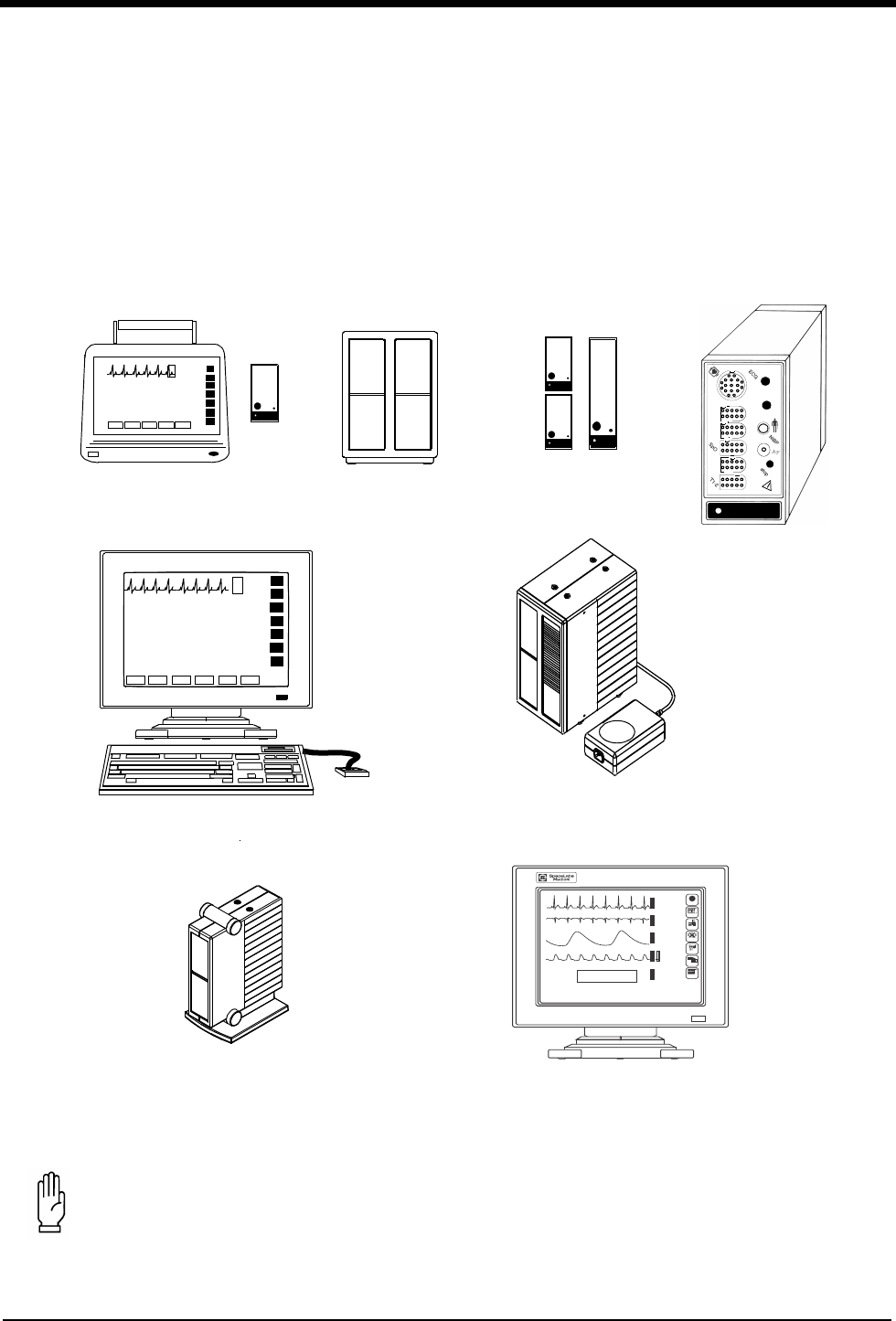
Figure 1-1: Ultraview Care Network Monitor Family
CAUTION:
• Federal law restricts these devices to sale by, or on the order of, a physician.
Modules
90491 Module
Housing
module
90367 Ultraview 1030 Monitor
90369 Ultraview 1050 Monitor
90385 UCW® Monitor 90364 Ultraview 1600 Monitor
90387 Ultraview 1700 Monitor
90363 Ultraview 1500 Monitor
adult
NIBP
NIBP
SpO
2
P1-2
P3-4
CO
hlo
2
hlo
1
2
90496 Ultraview
Command Module
90499 Module Housing
15:55 110/ 68( 84) mmHg HR= 69 (ECG)
16:54 115/ 68( 77) mmHg HR= 69 (ECG)
16:55 113/ 55( 88) mmHg HR= 69 (ECG)
16:56 108/ 56( 82) mmHg HR= 69 (ECG)
16:57 116/ 62( 83) mmHg HR= 69 (ECG)
E
C
G
E
C
G
R
E
S
P
S
P
O
2
N
I
B
P
LAST BP=
16:57
02/21
116
62
97
20
69
68
bpm
%
( 83)
m
m
H
g
150
100
100
85
30
0
ROW 5
120
40
RA-LA
V3
ST=-0.16
♥ II MON
ST= 0.08
A=0
*
S
*
21 FEB 1994
?
HELP
MONITOR
SETUP
SPECIAL
FUNCTIONS
R
X
TONE RESET
ALM SUSPEND
RECORD
PREVIOUS
MENUS
NORMAL
SCREEN
Color Display, CRT or flat panel
with Touchscreen

1-2
Contents
System Introduction and Network
Basics
System Basics
Ultraview Care Network monitors provide a consistent operator interface across
all bedside and central monitoring environments. Monitors installed on a network
provide access from monitor to monitor and enable you to control the remote data.
Networked monitors enable you to view waveforms and numeric values of patient
parameters, review vital sign and ECG arrhythmia and ST history, and record
patient data automatically during alarm events. Refer to Network Basics on
page 1-8 for more information.
• Central stations display patient specific parameters, remote alarms, and
alarm limits that are based on the setting of the bedside as determined by the
primary caregiver. Refer to Central Monitors on page 6-3 for detailed
information on the system capabilities.
• The Remote View feature enables you to monitor two patients
simultaneously. Remote views of waveforms and numerics are nearly
identical in display and function to the parameter at the originating monitor.
Alarms, trends, menu keys, and recordings are accessible through a Remote
View. Refer to Viewing Remote Parameters on page 1-9 and Alarms on page
2-3 for more information.
• The Full Bed Review feature enables you to view multiple parameters on a
UCW and Ultraview 1700 bedside monitor from any other bedside or central
monitor on the network. Refer to Full Bed Review - UCW and Ultraview 1700
Only on page 1-11 for more information.
• The Alarm Watch feature notifies you when an alarm occurs on any other
monitor on the network. Refer to Alarm Watch on page 2-7 for more
information.
• Vital signs trending provides minute-by-minute recording of parameter data
for review and for documentation in the patient record. You select the format
and interval for trending. Refer to Trends on page 26-3.
• Optional calculations features provide automatic calculation and trending of
advanced clinical variables including hemodynamic, renal, oxygenation,
ventilation calculations, and drug dosage. Refer to Calculations on page
25-5.
System Basics . . . . . . . . . . . . . . . . . . . . . . . . . . . . . . . . . . . . . . . . . . . . . . . . . .2
Monitor Basics . . . . . . . . . . . . . . . . . . . . . . . . . . . . . . . . . . . . . . . . . . . . . . . . . .3
Power Failure . . . . . . . . . . . . . . . . . . . . . . . . . . . . . . . . . . . . . . . . . . . . . . . . . . .4
Network Basics . . . . . . . . . . . . . . . . . . . . . . . . . . . . . . . . . . . . . . . . . . . . . . . . . .8
Watching Alarms Remotely - Alarm Watch. . . . . . . . . . . . . . . . . . . . . . . . . . . . .9
Viewing Remote Parameters . . . . . . . . . . . . . . . . . . . . . . . . . . . . . . . . . . . . . . .9
Full Bed Review - UCW and Ultraview 1700 Only . . . . . . . . . . . . . . . . . . . . . .11
Reviewing Remote Trends . . . . . . . . . . . . . . . . . . . . . . . . . . . . . . . . . . . . . . . .12

System Introduction and Network Basics
1-3
Monitor Basics
Ultraview Care Network monitors use modules to monitor various clinical
parameters. For example:
• Electrocardiograph (ECG). Refer to ECG on page 8-3.
• Noninvasive Blood Pressure (NIBP). Refer to NIBP on page 13-3.
• Cardiac Output (CO). Refer to Cardiac Output on page 19-3.
Remote module housing units may be used with Ultraview Care Network monitors
to house additional modules. The 90385 Universal Clinical Workstation (UCW®),
90363 Ultraview 1500, 90364 Ultraview 1600, and 90387 Ultraview 1700 monitors
must use a remote module housing unit to house any of its modules.
• Each 90499 module housing holds up to two modules.
• Each 90491 module housing holds up to four modules.
An external power supply is needed whenever a module housing is used. A
separate power supply is required for the 90491 and 90499 module housing.
WARNING:
• Due to the potential for electromagnetic interference,
portable communication transmitters and cellular phones
should not be operated within 3.5 feet (1.07 meters) of the
patient, patient leads, or associated patient monitoring
equipment.
!
• All references to the Universal Clinical Workstation or UCW
include the Universal Clinical Workstation-Independent Display
(UCW-ID), and all the available features of the UCW-ID.

Ultraview Care Network
1-4
Power Failure
Modules are designed with default settings for alarms and various other
parameter settings (for example, NIBP reading frequency) which you may adjust
to meet the needs of your patients. When events occur that might cause the
selected limits or values to return to the monitor default settings, the monitor may
display a CHECK SETUP key in the ECG zone combined with a low priority alarm
tone (refer to Setting Alarm Limits on page 2-4 for details on alarm priorities). To
cancel the message and the alarm, simply touch the CHECK SETUP key on the
screen.
The following describes the events that will cause the CHECK SETUP key to
appear.
WARNING:
• In the case of a power failure, the remote module housing
(90491 or 90499) provides +5 V of power to maintain data
integrity.
• If the power is interrupted to the remote module housing
but not to the monitor, the module will remain active and
the following will occur:
• Waveforms will go flat (as if the patient has no vital
signs) or will be totally lost.
• Parameter values will go to the minimum limit or ???
(except for non-invasive pressure, which will display
the last value before the power failure).
• Alarms may sound for low limit violations or for
conditions such as Asystole, Leads Off, Loss of Signal,
or Adapter Disconnected.
• If any of the above conditions occur, check to determine
whether or not power has been interrupted to the remote
module housing and reestablish AC power.
• Do not allow the Ultraview 1600, Ultraview 1700, or the
90499 module housing to be left turned ON without power
applied for long periods of time or the memory backup
batteries will be depleted.
Event Reason
Monitor power ON
Any time you power ON a monitor, all parameters are
reset to their default values or to the values set the
last time the monitor was in use. It is very important
to review the parameter limits and/or their values and
adjust them appropriately for the current patient.
When you insert an
ECG module
Because the module values will come up with default
settings, it is important to review and reset the limits
and/or values for that particular patient.
An error is detected
and the monitor resets
The monitor has detected an error that cannot be
corrected through other means.
System Introduction and Network Basics
1-5
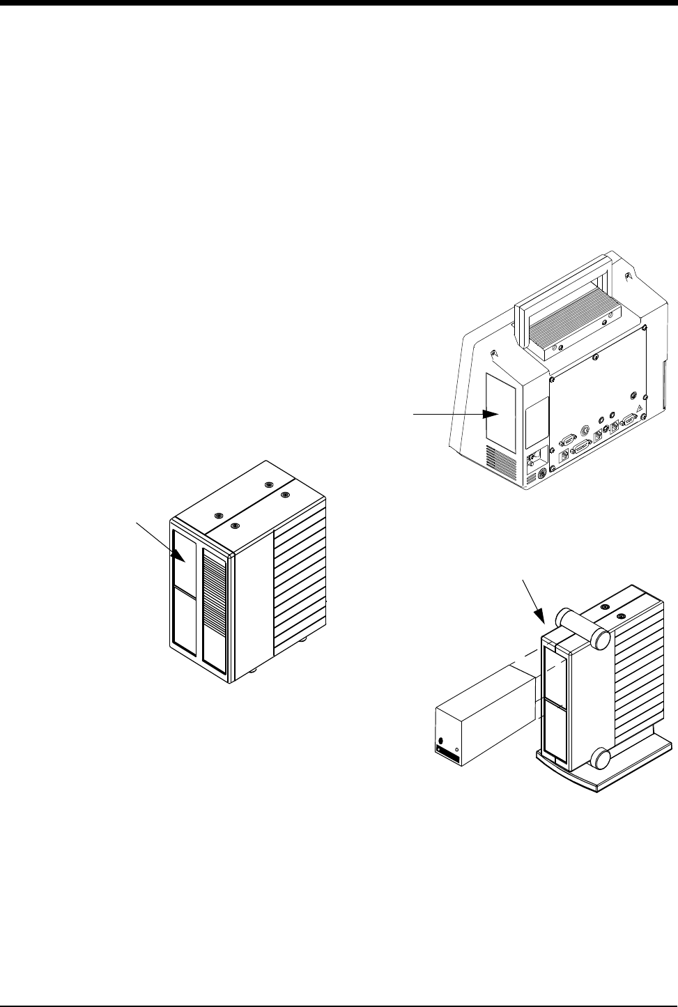
Inserting Modules
Insert a module into the bedside monitor (Ultraview 1030/1050) or into the remote
module housing as shown below.
Figure 1-2: Ultraview Care Network module insertion
Patient Preparation
To prepare the patient for monitoring, attach the patient cable, and connect the
patient cable to the module. Touch a parameter key, then touch the menu keys as
needed to set up monitoring for a specific parameter.
!
• Check Setup is an optional feature on the ECG channel.
Contact your system administrator if your system does not have
this feature.
remote module housing
Ultraview 1030/1050
right side view
patient
module
slot
90499 Module Housing
patient
module
slot
Ultraview 1600 and
Ultraview 1700 Monitors
Ultraview Care Network
1-6
Using the Monitor Screen
Ultraview Care Network monitors employ touchscreen technology for interaction
with the system. To activate a menu or parameter key, simply touch the key on the
screen.
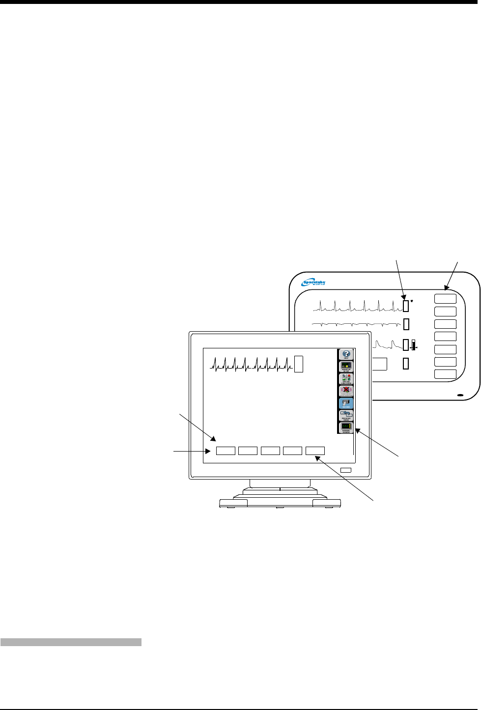
Using the Screen Keys
The Ultraview Care Network monitors use keys on the screen to execute monitor
functions. The monitor keys are located to the far right side of the screen and have
standard functions regardless of the parameter being monitored. The menu keys
appear along the bottom of the screen as menu items. The (physiological)
parameter keys appear next to the parameter display. Some monitors (for
example, the UCW) display these keys pictorially as icons, but the key names and
functionality are the same for all Ultraview Care Network monitors.
Figure 1-3: Screen keys
Menu and Parameter Keys
The menu and parameter keys appear on the monitor screen as displayed in
Figure 1-3.
• Touch a parameter key to display a set of menu keys for that parameter
• Touch a menu key to control a monitoring function, for example, ALARM
LIMITS
Keys that are currently active appear in bold lettering. Inactive keys appear in dim
lettering. When you touch an inactive key an error tone will sound.
Touch the HELP key, and then the key in question, to display a description of its
function in the system message area above the menu line.
monitor
keys (Icons)
monitor
keys
parameter
keys
menu keys
menu
line
message
area
PRINTER
CONTROLS
11:32
11:33
11:34
11:35
11:36
110/ 69( 84)
113/ 73( 88)
113/ 69( 84)
82/ 51( 64)
108/ 67( 83)
TEMP
34.7
To obtain help about a menu key:
1Touch HELP.
2Touch the desired menu key.

System Introduction and Network Basics
1-7
Touch the MONITOR SETUP key to display a menu that enables you to adjust
tones, enter patient data, modify the screen format, set time and date, adjust
brightness, determine battery status (Ultraview 1030/1050 only), and specify
printing characteristics.
The UCW and Ultraview 1700 enable you to display a digital clock, stopwatch, or
timer in the lower right corner of the screen. Touch the clock to display the clock
menu. The Ultraview 1030, 1050, 1500, and 1600 monitors display a digital clock
at the bottom right of the screen. Refer to Bedside/Transport Monitors on page 5-3
and Central Monitors on page 6-3 for a detailed explanation of the functions that
apply to your system.
Touch the SPECIAL FUNCTIONS key to display a menu that enables you to view
remote parameters, activate automatic notification of remote alarms, view trends
of vital sign data and clinical and drug calculations, and use other optional network
applications.
When you touch the TONE RESET/ALM SUSPEND key once during an alarm
condition it will silence the alarms for 45-seconds at the unit where the key was
touched (bedside or central). Touching the key again during the initial 45-second
suspension will silence the alarms for 3-minutes at the bedside only. Refer to
Alarms on page 2-3 for more details.
You may use either a system printer or a printer module for recording patient data.
Recordings of monitored data can be generated by touching the RECORD key
and then touching up to four flashing parameter keys (depending on the printer
capacity). Refer to Printing on page 4-5 for more details.
Touch the PREVIOUS MENU key to move back one menu level. From the Main
Menu level, touch PREVIOUS MENU to remove the current menu from the
display and close the application window.
Touch the NORMAL SCREEN key to close any active application window, and its
menus, or to return to the basic display.
Using the Keyboard
A keyboard can be used for certain applications like Calculations and
Admit/Discharge. An on-screen keyboard is provided for all local applications, but
you may also use an external keyboard. Refer to Using the On-Screen Keyboard
on page 3-5 for keyboard displays. Use the arrow keys and TAB key on the
keyboard to move within an application window.
Using the Mouse
If your system is equipped with a mouse it may be used with selected functions in
lieu of the keyboard or touchscreen. Click the left mouse button on a menu key to
activate the key.
To customize your monitor:
1Touch MONITOR SETUP.
2Select any menu key.
To activate additional functions:
1Touch SPECIAL FUNCTIONS.
2Select any menu key.
To temporarily silence alarm
tones:
1Touch TONE RESET/ALM
SUSPEND once to silence for
45-seconds.
2Touch TONE RESET/ALM
SUSPEND again (within
45-seconds) to suspend alarms
for 3-minutes (bedside only).
To record a parameter:
1Touch RECORD once.
2Select up to four flashing
parameter keys.
To change the screen display:
1Touch PREVIOUS MENU to
return to last menu.
2Touch NORMAL SCREEN to
remove the menu from the
screen.
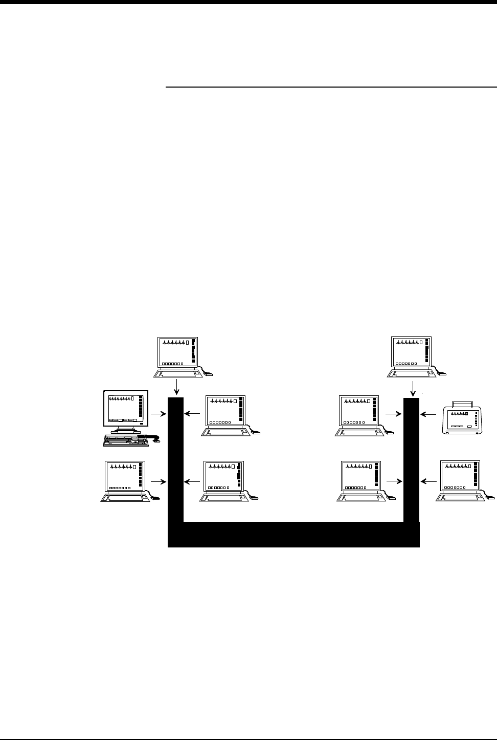
Ultraview Care Network
1-8
Network Basics
To aid in understanding the concept of a network operation, consider your need to
communicate between beds in a single care unit. While you are in the care unit at
a bedside monitor, you can view parameter waveforms from another bed and
control those parameters just as if you were at that remote bedside.
Advanced networking allows remote access and interaction with Clinical and Drug
Calculations, Tabular Trends, Graphic Trends, and parameters from remote beds.
Standard networking allows the remote viewing of single parameters from bedside
to bedside, and bedside to central. The Full Bed Review feature on the UCW and
Ultraview 1700 allows remote viewing of the entire bedside monitor.
If you need to review information from another unit on the network, you can do so
by specifying the unit as well as the bed. For example, if you have a need for
frequent communication between your care unit and another care unit, those units
would be designated as subnets on your networked system. This identification
typically appears on the keys in the appropriate menus.
The following figure illustrates a possible network configuration.
Figure 1-4: Network configuration
Although the presence of the network is invisible to you as you operate any
monitor on the system, decisions were made during installation to configure the
system according to your hospital’s specifications. Typically, hospitals designate a
system administrator for this task. This manual directs you to refer questions to
that individual where system operation may differ according to the decisions made
by your hospital.
Subnet #1
Intensive Care Unit
Subnet #2
Emergency Room
NETWORK

System Introduction and Network Basics
1-9
Watching Alarms Remotely -
Alarm Watch
With the network Alarm Watch function enabled you will be notified of all alarms at
all monitors. Once a monitor has been set up to Alarm Watch a bed, any alarm
from that bed is reported.
Refer to Alarm Watch on page 2-7 for more information.
Viewing Remote Parameters
Each parameter on a bedside monitor can be independently viewed (Remote
View) on any other bedside or central monitor on the network. Remote views of
parameters can be identical in display and function to the local bedside, with the
addition of the patient name and bed identification label.
If enabled by your system administrator alarms and menu keys operate the same
at the remote monitor as they do at the local bedside.
Bedside monitors can have parameters remotely viewed by up to 16 other
devices.
Remotely viewed parameters occupy the lowest zone on the screen of a bedside
monitor. On the central monitor each remote parameter is assigned a specific
display position. Every Remote View zone is separated from other zones by a
dividing line.
WARNING:
• The Alarm Watch function is not automatically enabled.
You must first select the bed that the central or bedside
monitor should Alarm Watch.
• Alarm conditions for parameters not currently displayed on
the central monitor will only be reported at a central
monitor when Alarm Watch is enabled at the central
monitor.
!
• Your network protocol may not enable you to make remote
alarm limit changes or to remotely control a parameter. If you
have a question regarding this function, ask your system
administrator.
To enable Alarm Watch:
1Touch SPECIAL FUNCTIONS.
2Touch ALARM WATCH.
3a Select a bed or a subnet.
3b If you selected a subnet, then
select a bed.
4Touch ALARM WATCH
ENABLE.
To view remote parameters from
a bedside monitor:
1Touch SPECIAL FUNCTIONS.
2Touch REMOTE VIEW.
3a Select a bed or a subnet.
3b If you selected a subnet, then
select a bed.
4Select desired parameter.
To view remote parameters from
a central monitor:
1Touch MONITOR SETUP.
2Touch SCREEN FORMAT.
3Select the destination display
zone.
4Select a subnet or bed as
appropriate.
5Select a parameter and color.
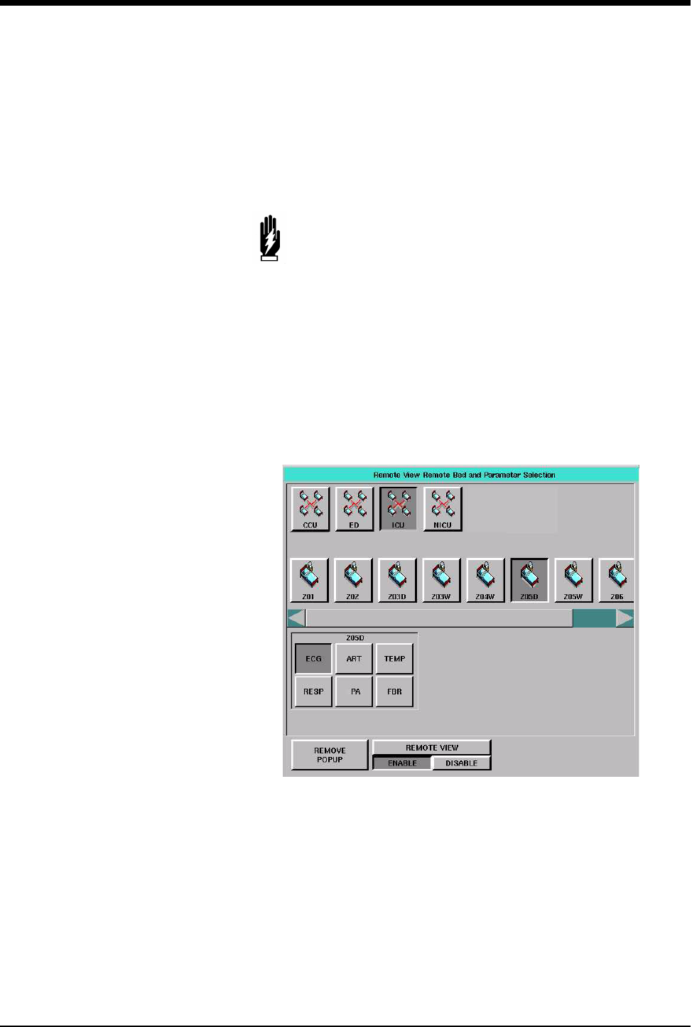
Ultraview Care Network
1-10
When a bedside monitor is set up to remotely view a parameter from another
bedside, a one-second advisory tone sounds at the onset of the alarm condition.
The remote alarm tones must be active at that bedside monitor.
Arrhythmia and ST segment review data can also be viewed from remote
monitors if optional Arrhythmia and ST segment analysis software is part of your
system.
When you need to control or continually observe a parameter from a remote
monitor, use the Remote View function. When you wish to have remote
notification of alarms, use the Alarm Watch function.
Figure 1-5: Remote View (UCW/ Ultraview 1700)
WARNING:
• Remote View and Alarm Watch are mutually exclusive
functions on the bedside monitor. Selecting to remotely
view a parameter at a bedside inactivates the Alarm Watch
function at that monitor.
!
• Your network protocol may not allow you to control remotely
viewed parameters. If you have a question regarding this
function, ask your system administrator.

System Introduction and Network Basics
1-11
Full Bed Review - UCW and
Ultraview 1700 Only
The Full Bed Review (FBR) key allows you to view several parameters from
another monitor at your bedside or central station monitor. The monitor at which
the Full Bed Review is enabled will display all available parameters from the
remote monitor within the limitations of the capabilities of the displaying monitor.
Whenever a bedside or central monitor is displaying another monitor’s data, an
FBR key appears in the lower left corner if no menus are displayed. Full Bed
Review can be activated by touching this FBR key, then selecting one of the
flashing parameter keys. If the monitor is not displaying another monitor’s data,
Full Bed Review can be activated by touching the FBR key that follows the last
parameter icon for the selected bed.
If more parameters are available from the remote bedside than FBR can display,
keys for these additional parameters are displayed as numeric keys along the
bottom of the screen. Selecting any of these numeric keys causes the selected
parameter to replace the lowest parameter.
The parameter keys displayed by FBR are interactive. To access the controls for a
parameter, touch that parameter’s key. Remote review of trended or calculated
data for the selected monitor is available by touching the TRENDS/CALCS key
found in the Special Functions menu.
To deactivate the FBR feature, touch NORMAL SCREEN.
!
• Full Bed Review displays a single ECG lead if the remote
bedside is configured to display ECG data using the Full View or
Split View format.
To activate Full Bed Review at a
bedside monitor when a remote
view is not displayed:
1Touch SPECIAL FUNCTIONS.
2Touch REMOTE VIEW.
3Select one of the subnet icons,
then select a bed icon.
4a Touch the FBR key displayed
after the last parameter icon for
that bed.
-OR-
4b Select any parameter icon,
then perform the steps in the
following Quick Start.
To activate Full Bed Review
when a remote parameter is
already displayed:
1Touch NORMAL SCREEN, if
needed, to display all
parameters.
2Touch FBR displayed in the
lower-left corner of the monitor.
3Touch the flashing parameter
key of the selected remote bed.
To activate Full Bed Review at a
central monitor without
parameters already displayed:
1Touch MONITOR SETUP.
2Touch SCREEN FORMAT.
3Select one of the subnet icons,
then select a bed icon.
4a Touch the FBR key displayed
after the last parameter icon for
that bed.
-OR-
4b Select any parameter icon, and
select a display zone to assign
that parameter to that display
zone.
5Follow the steps in the previous
Quick Start.
To deactivate the Full Bed
Review:
1Touch NORMAL SCREEN.

Ultraview Care Network
1-12
Reviewing Remote Trends
Retrospective vital sign review through either graphic or tabular trends provides
minute-by-minute access to data from any monitor on the network.
To display a trend from a remote
monitor:
1Touch SPECIAL FUNCTIONS.
2Touch REMOTE TRENDS/
CALCS.
3a Select a bed or a subnet.
3b If you selected a subnet, then
select a bed.
4Touch GRAPHIC TRENDS or
TABULAR TRENDS.
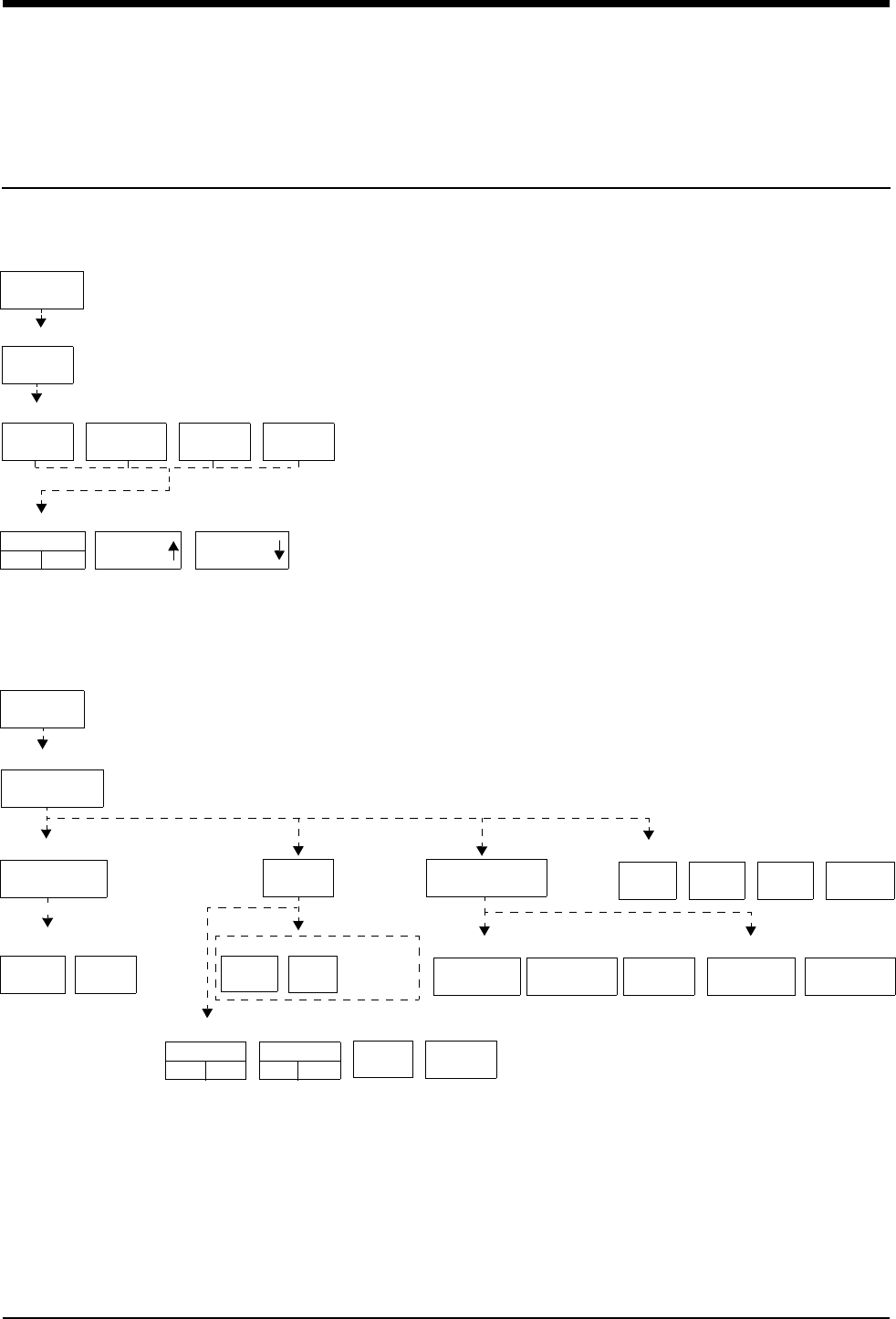
2-1
!
• Based on features purchased, more or fewer keys may appear here than on your menu screens.
Alarms Directory
Directory of Keys
Adjusting Alarm Tones
TONE
OFF
MONITOR
SETUP
TONES
REMOTE
ALARMS
ALARM
WATCH
KEY
TONE
LOCAL
ALARMS
VOLUME VOLUME
MONITOR
SETUP
RECORDER
CONFIG.
RECORDING
DURATION
ALARM
PARAMS
MORE
Setting Up Automatic Alarm Recordings
MONITOR SETUP
MONITOR SETUP - Select type of tone to change
MONITOR SETUP - LOCAL ALARM TONE
MONITOR SETUP
RECORDER CONFIGURATION
Select parameters which require alarm recordings from BED X
RECORDING
DESTINATION
NETWORK BOTH
ALARM RECORDINGS TO
THIS
MONITOR
12 SEC 20 SEC
On Central only - Select Bed
BED X ...
Select duration for recordings
initiated from this monitor
124VITALS
SETUP
Number of recorder channels
THIS NETWORK
MONITOR
OTHER RECORDINGS TO
ON
ECG
ON OFF
RESP
ON OFF ...
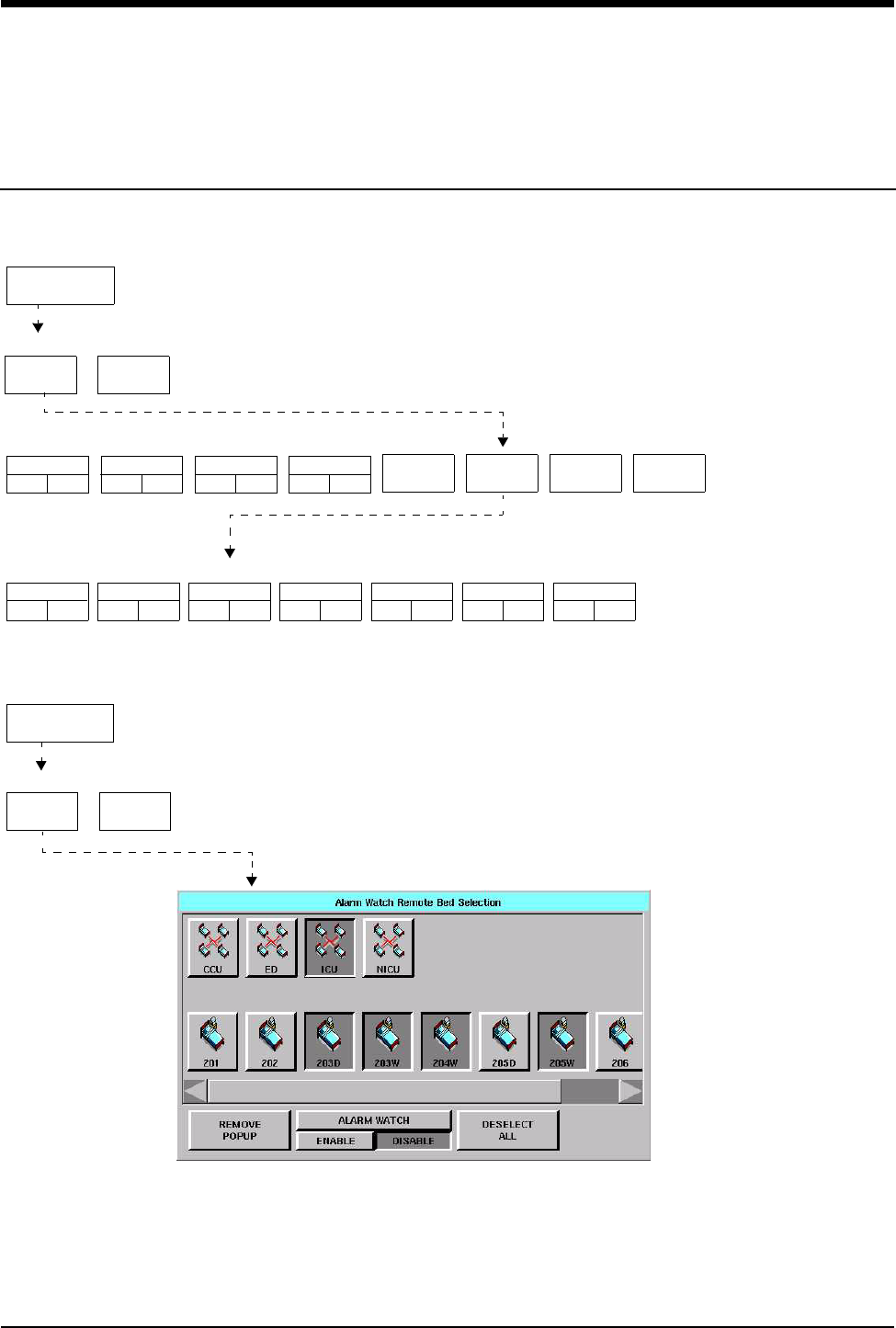
Alarms Directory
!
• Based on features purchased, more or fewer keys may appear here than on your menu screens.
2-2
Directory of Keys
SPECIAL
FUNCTIONS
ALARM
WATCH
RV/AW
OFF
NET 02 NET 03 NET 04 MORE
SPECIAL FUNCTIONS
ALARM WATCH - Select bed(s) for ALARM WATCH
ALARM WATCH - Select bed(s) for ALARM WATCH in subnet NET03
1001
ON OFF
1002
ON OFF
1003
ON OFF
1004
ON OFF
3001
ON OFF
3002
ON OFF
3003
ON OFF
3004
ON OFF
3005
ON OFF
3006
ON OFF
3006
ON OFF
Setting Up Alarm Watch (1030/1050/1500/1600)
Setting Up Alarm Watch (UCW/Ultraview 1700)
SPECIAL
FUNCTIONS
ALARM
WATCH
RV/AW
OFF
SPECIAL FUNCTIONS

Contents
2-3
Overview . . . . . . . . . . . . . . . . . . . . . . . . . . . . . . . . . . . . . . . . . . . . . . . . . . . . . . . 3
Default Alarm Limits. . . . . . . . . . . . . . . . . . . . . . . . . . . . . . . . . . . . . . . . . . . . . . . 3
Setting Alarm Limits. . . . . . . . . . . . . . . . . . . . . . . . . . . . . . . . . . . . . . . . . . . . . . . 4
Identifying Alarm Levels. . . . . . . . . . . . . . . . . . . . . . . . . . . . . . . . . . . . . . . . . . . . 4
Adjusting Alarm Tones/Key Tones . . . . . . . . . . . . . . . . . . . . . . . . . . . . . . . . . . . 5
Controlling Alarms via the TONE RESET/ALM SUSPEND Key . . . . . . . . . . . . . 6
Alarm Watch . . . . . . . . . . . . . . . . . . . . . . . . . . . . . . . . . . . . . . . . . . . . . . . . . . . . 7
Automatic Recording of an Alarm . . . . . . . . . . . . . . . . . . . . . . . . . . . . . . . . . . . 10
Alarms Troubleshooting Guide . . . . . . . . . . . . . . . . . . . . . . . . . . . . . . . . . . . . . 11
Alarms
Overview
This chapter describes how to use the Alarm Watch feature, set alarm limits,
silence and suspend alarms, set alarm tones, and specify parameters for
automatic alarm recordings.
When a parameter goes into alarm on a local bedside monitor, the corresponding
parameter key flashes on the screen, an alarm message is displayed, and an
alarm tone sounds (unless tones are disabled). You can also choose to
automatically record the parameter in alarm on a bedside or network printer.
Networked monitors enable you to monitor alarm conditions at both the central
and bedside monitors simultaneously through the Alarm Watch feature.
Default Alarm Limits
Factory default alarm limit settings are activated whenever the monitor is powered
ON, whenever a module is inserted, or when a parameter is enabled. You can
modify these settings to meet your own protocols.
Refer to the Alarm section of the appropriate parameter chapter in this manual for
details concerning setting or adjusting alarm limits for a specific parameter.
WARNING:
• Alarm conditions for which you want to be alerted must be
set to ON or enabled at the location where you want to be
alerted, bedside or central. You can enable them from the
local bed, remote bed, or central.
!
• Define your own default settings for alarm limits, alarm
priorities, recordings, and other attributes with the Module
Configuration Manager feature. Refer to Module Configuration
Manager on page 7-5 for further details.

Ultraview Care Network
2-4
Setting Alarm Limits
You can change parameter alarm limits by using the parameter’s Alarm Limits
menu. The steps to the left illustrate the minimum procedure used to adjust high
and low alarm limits for a parameter.
Identifying Alarm Levels
Alarm conditions are visually and audibly prioritized as high, medium, or low.
* The repetition rate for the tone bursts on the High, Medium, and Low levels may
be adjusted for all monitors by your system administrator.
!
• Parameters may contain additional alarm limit features not
listed here. Read the specific parameter chapter (for example,
ECG or NIBP) in this manual for details.
• To set fetal alert limits, please refer to Fetal Monitoring on page
15-3 for further details.
Table 1: Bedside Alarms
Priority Tone Type* Visual Tone Duration
High Continuous tone, or 2
bursts of 5 tones every
15-seconds
Flashing key; message
appears in red on color
monitors
Until the alarm condition is
resolved, the alarm is
suspended, or the tone is reset
Medium Intermittent tone (one
second ON, one second
OFF), or burst of 3 tones
every 30-seconds
Flashing key; message
appears in yellow on
color monitors
Until the alarm condition is
resolved, the alarm is
suspended, or the tone is reset
Low Intermittent tone (one
second ON, four
seconds OFF), or 1 tone
every 30-seconds
Flashing key; message
appears in yellow on
color monitors
Until the alarm condition is
resolved, the alarm is
suspended, or the tone is reset
WARNING:
• Parameters shown in the ECG waveform zone in Enhanced
Vital Signs mode do not alarm at the central station. Only
parameters set via the Alarm Watch mode will alarm as set
up by the system administrator.
To set alarm limits:
1Touch a parameter key (ECG,
TEMP, etc.).
2Touch ALARM LIMITS.
3Ensure ALARMS ON is set.
4Select HI = or LO =.
5Use arrow keys to adjust.

Alarms
2-5
* The repetition rate for the tone bursts on the High, Medium, and Low levels can
be adjusted for all monitors by your system administrator.
Adjusting Alarm Tones/Key Tones
You can turn the alarm tone ON or OFF and adjust the tone volume for local
alarms, Remote View alarms, or Alarm Watch alarms. While you are adjusting
tone volume, a tone sounds briefly as an example of the new level.
Alarm tones refer to the sound associated with an alarm condition. Key tones
sound each time you touch a screen key.
Volume adjustments affect only the monitor where the adjustment is made. The
tone volume of an alarm notification at a remote monitor must be adjusted at that
monitor. It cannot be adjusted remotely. A visual alarm notification is displayed
until the condition is resolved, even if you disable the alarm tones at that monitor.
Alarm Watch tones sound when the Alarm Watch feature is active and an alarm
condition exists on a watched monitor. The Alarm Watch feature must be enabled
via the Special Functions menu for the Alarm Watch tone to sound.
The Remote View alarm tone only sounds when a remotely viewed parameter
goes into alarm.
Table 2: Alarm Watch and Remote View Alarms
Priority Tone Type* Visual Tone Duration
High Central
continuous tone, or 2 bursts
of 5 tones every 15-seconds
Bedside
one single tone
flashing key; message
appears in red on color
monitors
Central
until the alarm condition is
resolved or the tone is reset
Bedside
one-second
Medium Central
intermittent tone (one
second ON, one second
OFF), or burst of tones
every 30-seconds
Bedside
one single tone
flashing key; message
appears in yellow on
color monitors
Central
until the alarm condition is
resolved or the tone is reset
Bedside
one-second
Low Central
intermittent tone (one
second ON, four seconds
OFF), or one tone every
30-seconds
Bedside
one single tone
flashing key; message
appears in yellow on
color monitors
Central
until the alarm condition is
resolved or the tone is reset
Bedside
one-second
WARNING:
• Disabling alarm tones via Monitor Setup at a bedside or at a
central monitor eliminates alarm tones for all alarm
conditions at that monitor, even in the case of life-
threatening events.
To set local alarm tones or key
tones:
1Touch MONITOR SETUP.
2Touch TONES.
3Select LOCAL ALARMS or KEY
TONE.
4Select TONES ON.
5Use VOLUME↑ and VOLUME↓
keys to adjust.
To set alarm watch tones or
remote view tones:
1Touch MONITOR SETUP.
2Touch TONES.
3Select ALARM WATCH or
REMOTE ALARMS.
4Select TONES ON.
5Use VOLUME↑ and VOLUME↓
keys to adjust.

Ultraview Care Network
2-6
Controlling Alarms via the
TONE RESET/ALM SUSPEND Key
During an Alarm Condition
If you touch TONE RESET/ALM SUSPEND once at a monitor during an alarm
condition:
• The alarm tone is silenced at that monitor for 45-seconds, but the alarm tone
continues to sound at other monitors. If the alarm condition continues, the
alarm tone resumes at that monitor at the end of the 45-second period. If
another parameter goes into alarm during this period, or if the initial condition
ends and then begins again, the alarm tone will again sound at that monitor.
• The message ALARM TONES SUSPENDED FOR 45-SECONDS is
displayed only on that monitor.
• All flashing parameter keys continue to flash.
At a bedside monitor, when you touch the TONE RESET/ALM SUSPEND again
within 45-seconds:
• All alarms and alarm recordings are suspended for 3-minutes. No alarms
sound for any reason during this period, and no new alarm recordings are
produced.
• A message is displayed to indicate that all alarms are suspended.
• Trend data may not be collected. This feature can be enabled or disabled
only by your system administrator.
Normal alarm operation can be resumed within the 3-minute time period by
touching the TONE RESET/ALM SUSPEND or RESUME ALARMS key again.
In the Absence of an Alarm Condition
Touching the TONE RESET/ALM SUSPEND key once when no parameters are in
an alarm condition suspends the alarms at the bedside monitor. (Refer to During
an Alarm Condition on page 2-6.)
!
• The ALM SUSPEND feature is only available at bedside
monitors. If this feature has been disabled (set to OFF), the
TONE RESET/ALM SUSPEND key does not suspend alarms.
!
• The ALM SUSPEND key is relabeled as RESUME ALARMS
after the first key touch.
!
• The TONE RESET/ALM SUSPEND key is relabeled as ALARM
SUSPEND after the first key touch.
To silence an alarm tone for
45-seconds at any monitor, touch
the TONE RESET/ALM SUSPEND
key once.
To resume alarm tones at a
central monitor, touch the TONE
RESET/ALM SUSPEND key again
.
To suspend all alarms at a
bedside monitor for 3-minutes,
touch the TONE RESET/ALM
SUSPEND key again within
45-seconds.
Note: If alarms resume the
second time the key is touched,
your bedside monitor may be
configured differently for this
feature. Contact your system
administrator for details.
To resume normal alarm
operation at a bedside monitor
within the 3-minute period, touch
the TONE RESET/ALM SUSPEND
or RESUME ALARMS (Ultraview
1030, 1050, 1500, and 1600
monitors) key again.
To suspend alarms at a bedside
monitor when no alarm is
sounding, touch the TONE
RESET/ALM SUSPEND key once.

Alarms
2-7
To resume alarms at a bedside monitor, touch the TONE RESET/ALM SUSPEND
key again.
Alarm Watch
With the network Alarm Watch feature, you can be notified at a local bedside or
central monitor of all alarms from a remote bed. The Alarm Watch feature defaults
to its last setting when the monitor is turned ON. The local monitor displays the
message ALARM WATCH ON when the Alarm Watch feature for a remote bed is
active. On a central monitor, the message AW OFF also displays for each bed not
selected for Alarm Watch.
Refer to Viewing Remote Parameters on page 1-9 for more information. The listed
limits for the number of devices that can remotely view a monitor apply to Alarm
Watch-initiated remote views.
When a parameter from a monitor that is under Alarm Watch goes into alarm, a
message such as ALARM WATCH – BED 28 ECG CHANNEL IN ALARM
displays on the message line of the alarm-watching monitor. A one-time advisory
tone sounds at the watching bedside or central monitor. The corresponding
waveform appears in the lowest zone on the screen of the alarm-watching
monitor, unless:
• another alarm-watched parameter is in alarm and its waveform already
occupies that zone at the watching monitor,
-OR-
• a parameter is displayed in the lowest zone of the monitor and its parameter
key has been activated displaying a menu.
When a waveform for an Alarm Watch parameter in alarm displays, the
appropriate tone sounds at the bedside (once) and at the central monitors for the
duration of the alarm.
Only one Alarm Watch waveform can be viewed at a time. When subsequent,
concurrent alarms occur for one patient or other patients on Alarm Watch, a
message displays and a one-second advisory tone sounds. Remember to enable
Alarm Watch tones in the Monitor Setup menu to produce audible alarms.
!
• You cannot suspend alarms from a central monitor. However,
you can silence alarm tones for 45-seconds. Touching this key
has no effect if it is touched at the central monitor when no
alarm is sounding.
!
• A central monitor can be configured with the Central Alarm
Watch Manager to automatically Alarm Watch every bed it is
currently monitoring. Contact your system administrator about
this feature.
To enable Alarm Watch:
1Touch SPECIAL FUNCTIONS.
2Touch ALARM WATCH.
3a Select a bed or a subnet.
3b If you selected a subnet, then
select a bed.
4Ensure that the key for the
desired bed(s) has the ON
segment highlighted or is
indented.
5Touch ALARM WATCH
ENABLE for the UCW and
Ultraview 1700.
To disable Alarm Watch:
1Touch SPECIAL FUNCTIONS.
2Select RV/AW OFF.
To de-select beds for Alarm
Watch:
1Touch SPECIAL FUNCTIONS.
2Touch ALARM WATCH.
3a Touch the bed to de-select.
-OR-
3b Touch DESELECT ALL.

Ultraview Care Network
2-8
If multiple alarms occur simultaneously, the messages displayed cycle from one to
another every 3-seconds (up to a maximum of ten alarms) until all alarm
conditions are resolved, or until you disable alarms at either the local monitor
(through Remote View) or the remote monitor.
To resume Alarm Watch, touch the ALARM WATCH or ALARM WATCH ENABLE
(on the UCW and Ultraview 1700) key. Alarm Watch is resumed for all previously
selected patients. You can also add patients for Alarm Watch. The ALARM
WATCH ON message displays in the message zone whenever one or more
remote beds are selected for Alarm Watch from that local monitor.
If your hospital protocol requires remote monitoring of all alarms, you can activate
Alarm Watch during the setup of your bedside or central monitors. Alarm Watch
remains ON as long as you do not power down the monitor. Refer to Power
Failure on page 1-4 for further information.
Alarm Watch Rotation
On some monitors, your system administrator can configure the Alarm Watch
feature to rotate the visible active alarms through the Alarm Watch display zone
on the screen. Active alarms being monitored will rotate in and out of the display
zone at an interval set by your system administrator. The Alarm Watch rotation
time, signal tone, and rotation algorithm are set in the ALARM WATCH SETUP
menu, accessed by touching the PRIVILEGED ACCESS key.
ROTATE ALARM WATCH — enables the system administrator to turn the
rotation of alarms ON or OFF. If you select OFF, the ALARM WATCH ROTATION
and the ROTATION TIME options are unavailable.
ALARM WATCH ROTATION — enables the system administrator to select either
a rotation system allowing the higher priority alarms to rotate into the window
more often (Priority) or a simple rotation system allowing all alarms equal time in
the rotation regardless of the alarm priority.
ROTATION TIME — selects the interval between rotations in the Alarm Watch
window.
WARNING:
• Using the Alarm Watch feature, you can watch for alarms
from 32 other monitors. However, more than ten remote
alarms cannot be reported simultaneously to any monitor
using the Alarm Watch feature.
• Remote View and Alarm Watch are mutually exclusive
features on bedside monitors. If you select to Remote View
a parameter the Alarm Watch feature at that monitor is
inactivated.
ROTATE ALARM WATCH
ON
ALARM WATCH ROTATION ROTATION TIME
ALARM WATCH
SETUP
OFF PRIORITY SIMPLE 15 SEC 30 SEC

Alarms
2-9
Central Alarm Watch Manager
Your system administrator may have configured your central station monitor with
the Central Alarm Watch Manager feature enabled. This feature automatically
activates the Alarm Watch feature for all beds currently displayed on that central
monitor.
Alarm Tone Manager
The Alarm Tone Manager provides two levels of managing alarm notifications.
• If this feature is ENABLED, it will not allow individual alarm tones to be
permanently disabled.
• The system administrator can set a minimum volume for alarm tones
ensuring that they are always at a safe and audible level.
!
• When the Central Alarm Watch Manager is activated, it displays
alarms for each bedside that has the Alarm Watch feature
enabled. The central monitor continues watching for alarm
conditions from the selected bedside monitors until you disable
Alarm Watch for that bedside monitor or disable the Auto Alarm
Watch feature altogether.
• The factory default is Auto Alarm Watch ON with access to the
Auto Alarm Watch feature DISABLED.
• The Central Alarm Watch Manager must be set by a system
administrator with a Biomed level of privileged access.
!
• The factory default for the Alarm Tone Manager is OFF, which
inhibits access to the ALARM TONES keys in the Monitor Setup
menu.
• The Alarm Tone Manager must be set by a system
administrator with a Biomed level of privileged access.

Ultraview Care Network
2-10
Automatic Recording of an Alarm
Touch the ALARM PARAMS key to display a menu of parameters that can initiate
alarm recordings on a bedside recorder and on a network printer if the parameter
goes into an alarm condition. Recording on a network printer is configuration-
dependent. See your system administrator for details.
If alarm recordings are disabled for a parameter, no alarm recording is produced
on either the bedside or network printer. However, the designated alarm tones are
still generated and alarm messages are displayed.
Alarm recordings print the last 12- or 20-seconds (selectable under RECORDING
DURATION) of a waveform or print until the alarm stops or is suspended,
whichever is longer. To stop a recording at the bedside printer, touch STOP or
UNIT OFF on the printer module.
When a bedside recorder is present in the monitor and is selected and online, an
alarm recording is automatically directed to that recorder.
Use the key labeled OTHER ON/OFF for any new parameter not yet on the alarm
parameters menu.
!
• Spacelabs Medical strongly recommends verifying alarm
parameter settings on the monitor once per shift and upon each
admission.
• If a printer is not attached to the monitor, the recorder channel
(1, 2, 4) keys do not appear in the menu.
To select parameters for alarm
recording and generate
automatic recordings on a
bedside recorder:
1Touch MONITOR SETUP.
2Touch RECORDER CONFIG.
3Select RECORDING
DESTINATION.
4Select a destination for the
alarm recording.
5Touch PREVIOUS MENU.
6Touch ALARM PARAMS.
7Select parameter key(s) ON to
initiate a recording in case of
alarm. If the parameter key is
OFF, no alarm recording is
produced for that parameter in
an alarm condition.

2-11
Alarms Troubleshooting Guide
Clinical Situation Possible Cause Solution
Duplicate alarm recordings
print at the bedside and system
printer
■Alarm recording directed to both
bedside and network printers
under the RECORDING
DESTINATION key.
■Select THIS MONITOR or
NETWORK for alarm recordings.
No alarm recordings are
printed
■Parameters for alarm recordings
are set to OFF.
■Select parameters for alarm
recordings from the Alarm
Parameters menu or Record
Alarm Parameters menu.
■Bedside printer is OFF.
■The alarms have not been directed
to the bedside printer.
■ALARMS SUSPENDED for
3-minutes.
■Turn bedside printer ON.
■Ensure that THIS MONITOR or
BOTH is selected.
■Ensure that alarms are not
suspended.
■System printer is not identified as
one of two network printers.
■Have your system administrator
verify configuration.
■Printer is out of paper. ■Load paper into printer.
Alarms continue to violate after
touching TONE RESET
■More than one alarm may be in
violation.
■Touch TONE RESET/ALM
SUSPEND again.
No alarm notification occurs at
a central monitor
■The Alarm Watch function is not
active.
■Activate Alarm Watch for the
desired beds at the central.
■Parameters not displayed. ■Display the desired parameters
using SCREEN FORMAT under
MONITOR SETUP.
CANNOT INTERACT WITH
ALARM WATCH parameter
displayed
■The monitor may not be configured
to allow interaction with remote
parameters.
■Contact your system
administrator.
CANNOT deselect ALARM
WATCH
■The Ultraview Central Monitor is
configured with Central Alarm
Watch Manager to prevent de-
selection of automatically alarm
watched beds.
■Contact your system
administrator.

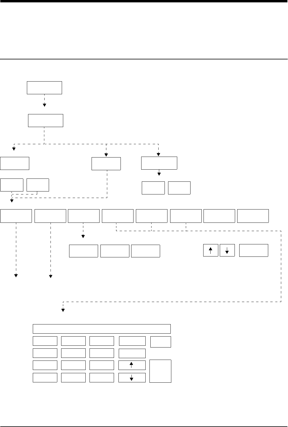
3-1
!
• Based on features purchased, more or fewer keys may appear here than on your menu screens.
Admit/Discharge Directory
Directory of Keys - Ultraview 1030/1050/1500/1600
MONITOR
SETUP
ADMIT/
DISCHARGE
ADMIT CHANGE
DATA DISCHARGE
YES NO
To enter patient name, ID, or other data
ADMIT- Purge existing data for this bed?
MONITOR SETUP
ADMIT/DISCHARGE - Select function
ID NAME WEIGHT
lb/kg
BSA
m2
ADULT
NEONATE
To enter height, weight, BSA (and calculations with Clinical Calculations feature)
on-screen keypad
Note: HEIGHT keypad
shown as an example
9
8
7
6
5
4
3
2
1
0
CLEAR
RESTORE
REMOVE
KEYPAD
ENTER
+/- .
HT 66.9
MALE
FEMALE
DATE OF
BIRTH
MONTH DAY ENTER
YEAR
ADMIT/DISCH. - Patient’s Date of Birth: DDMMMYYYY
HEIGHT
in/cm
Enter patient name/ID for bed xx
YES NO
DISCHARGE - Are you sure? (All data for the bed will be purged)
Select data you want to enter
on-screen
keyboard
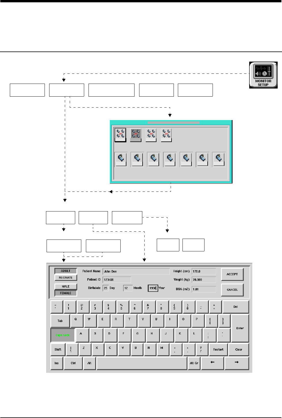
Admit/Discharge Directory
!
• Based on features purchased, more or fewer keys may appear here than on your menu screens.
3-2
Directory of Keys - UCW and Ultraview 1700
TONES ADMIT/
DISCHARGE MONITOR
CONFIG.
ADMIT CHANGE
DATA
YES NO
For bedside
For central
Admit - Purge existing data for this bed?
monitoring
monitoring
PRIVILEGED
ACCESS
DISCHARGE
ADMIT/DISCHARGE - Select function
MONITOR SETUP
NICU
BED01
BED01 BED02 BED03 BED04 BED05 BED06 BED07
ICU CCUMICU
MONITOR SETUP-Admit/Discharge: Select Bed
RECORDER
CONFIG.
YES NO
DISCHARGE - Are you sure? (All data for the bed will be purged)
To enter patient name, ID, or other data

Contents
3-3
Overview . . . . . . . . . . . . . . . . . . . . . . . . . . . . . . . . . . . . . . . . . . . . . . . . . . . . . . 3
Entering New Patient Information . . . . . . . . . . . . . . . . . . . . . . . . . . . . . . . . . . . 4
Changing Patient Information . . . . . . . . . . . . . . . . . . . . . . . . . . . . . . . . . . . . . . 9
Discharging a Patient. . . . . . . . . . . . . . . . . . . . . . . . . . . . . . . . . . . . . . . . . . . . . 9
Admit/Discharge Troubleshooting Guide . . . . . . . . . . . . . . . . . . . . . . . . . . . . . 10
Admit/Discharge
Overview
This chapter describes how to enter new patient data, change data for an existing
patient, and delete patient data from a Ultraview Care Network monitor.
You can access the Admit/Discharge menu on either the central or bedside
monitor. However, if you are accessing this menu at a central monitor, you must
also select the patient’s bed (this is not necessary at a bedside monitor).

Ultraview Care Network
3-4
Entering New Patient Information
The only information required when admitting a patient to the system is the
patient’s name (up to 40 characters). Entering the patient’s ID number (up to
15 characters) is optional.
This section discusses how to enter the following patient information, depending
on which monitor you have.
• Patient Name and ID (refer to Ultraview 1030/1050/1500/1600 and
UCW/Ultraview 1700 on page 3-5)
• Height, Weight, and BSA (body surface area) (refer to Entering Height,
Weight, and BSA on page 3-7)
• Date of Birth (refer to Entering Patient Date of Birth on page 3-8)
• Patient Type and Gender (refer to Entering Patient Type and Gender on page
3-9)
To enter new patient information
(Ultraview 1030/1050/1500/1600):
1Touch MONITOR SETUP.
2Touch ADMIT/DISCHARGE.
3Touch ADMIT.
4Select YES to purge the
existing data.
5Select ID and/or NAME.
6Enter information using the
on-screen keyboard.
7Touch ENTER.
8Touch PREVIOUS MENU
(if necessary).
9Select DATE OF BIRTH and
enter MONTH, DAY, and
YEAR.
10 Touch ENTER.
11 Touch PREVIOUS MENU.
12 Select HEIGHT, WEIGHT, or
BSA and enter information
using the on-screen keypad.
13 Touch ENTER.
14 Touch MALE/FEMALE until the
correct gender is highlighted.
15 Touch ADULT/NEONATE until
the relevant selection is
highlighted.
To enter new patient information
(UCW/Ultraview 1700):
1Touch MONITOR SETUP.
2Touch ADMIT/DISCHARGE.
3a Select a subnet or a bed
(central only).
3b If you selected a subnet, then
select a bed.
4Touch ADMIT.
5Select YES to purge the
existing data.
6Select a field on the on-screen
keyboard.
7Enter information using the
on-screen keyboard.
8Touch ENTER after completing
each field.
9Select ADULT or NEONATE.
10 Select MALE or FEMALE.
11 Touch ACCEPT to store the
new patient data.
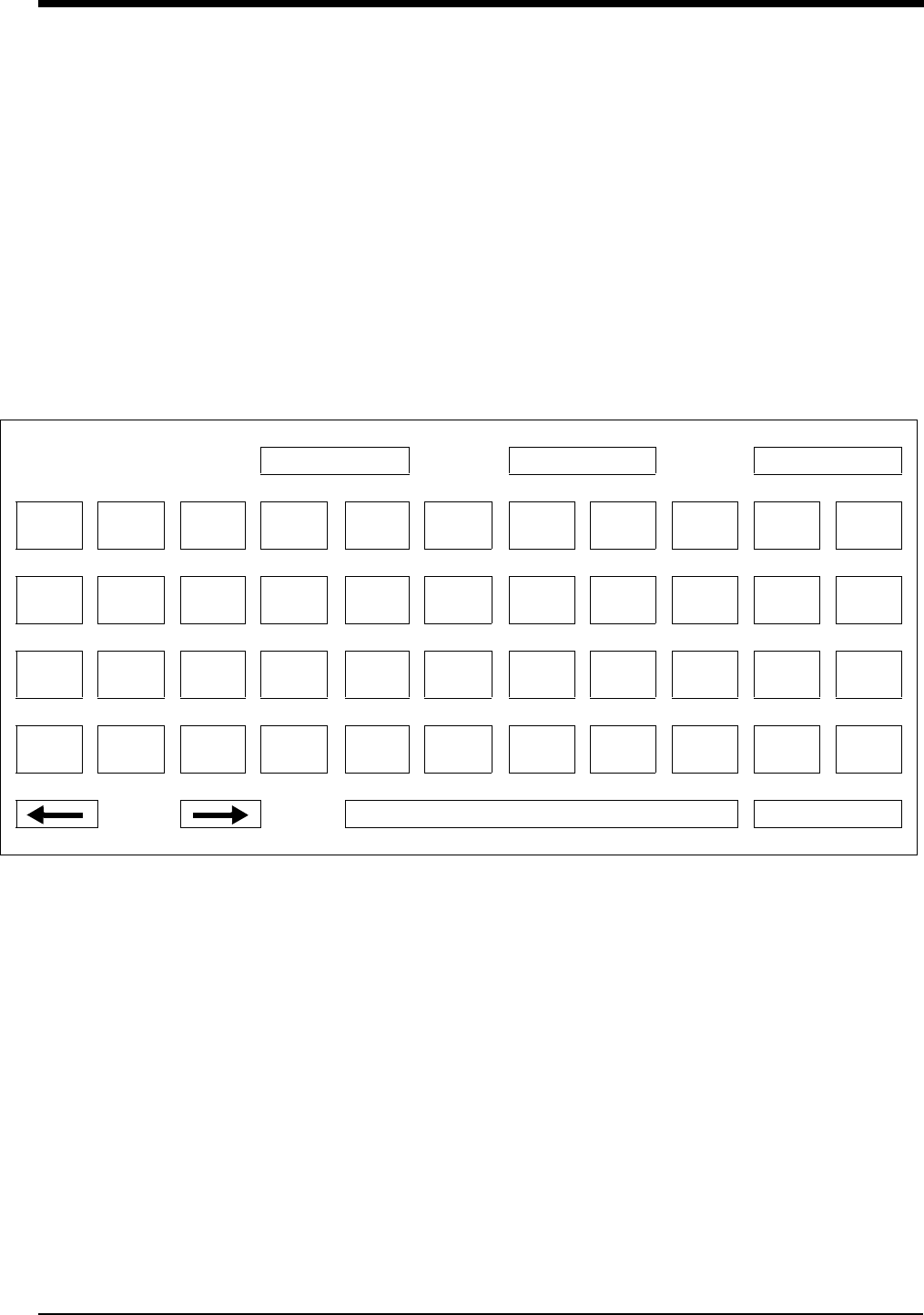
Admit/Discharge
3-5
Using the On-Screen Keyboard
A keyboard is displayed on the monitor screen as you begin the process of
admitting or changing data on a patient. The on-screen keyboard functions
differently depending on the monitor model you have. You can also use the
external computer keyboard to enter patient data into the selected field.
Ultraview 1030/1050/1500/1600
The keyboard shown in Figure 3-1 appears when you touch the NAME or ID key
under the ADMIT and CHANGE DATA keys. Use this keyboard to enter or change
the patient’s name or ID only.
Figure 3-1: Ultraview 1030/1050/1500/1600 on-screen keyboard
UCW/Ultraview 1700
The keyboard shown in Figure 3-2 appears when you touch the ADMIT or
CHANGE DATA keys. You can use this keyboard to enter or change ALL patient
information.
RESTART CLEAR BACKSPACE
!
1
@
2
#
3
$
4
%
5
^
6
&
7
*
8
(
9
)
0
_
-
QWER T Y U I O P “
‘
CAPS
LOCK ASD FGHJKL :
;
SHIFT Z X C V B N M <
,
>
.
?
/
ENTER
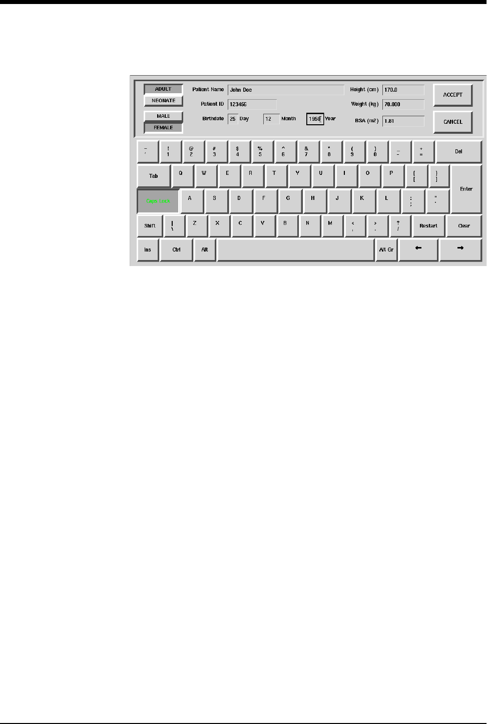
Ultraview Care Network
3-6
Figure 3-2: UCW/Ultraview 1700 on-screen keyboard
Character Keys — Each character key you touch displays above the keyboard
on the 1030, 1050, 1500 and 1600. It displays in the selected field on the UCW
and Ultraview 1700.
Function Keys —
DEL or BACKSPACE deletes the character to the LEFT of the cursor.
← moves the cursor left one position.
→ moves the cursor right one position.
RESTART redisplays the last name or value stored and deletes all earlier
changes.
CLEAR deletes the currently displayed name or value.
ENTER stores the data displayed in the selected field into system memory.
TAB moves the cursor to the next field.
CAPS LOCK locks the keyboard in all caps mode.
SHIFT toggles the shift mode on and off.
INS inserts the selected data in the current space.
SPACE BAR inserts a space.
ACCEPT enters the data into the system and completes the admit.

Admit/Discharge
3-7
Entering Height, Weight, and BSA
Table 1 lists the default values and valid ranges for height, weight, and BSA (body
surface area). You can adjust the values up or down within the valid range. The
values last set for height, weight, and BSA remain until manually changed.
The parameter value can be displayed in either U.S or metric units (see your
system administrator for details). The system automatically computes BSA from
the values entered for height and weight and uses this BSA value to obtain
indexed values for physiologic calculations such as Cardiac Output.
Toggle the ADULT/NEONATE key to display the respective adult and neonatal
default values for height, weight, and BSA.
Using the On-Screen Keypad (Ultraview 1030/1050/1500/1600 only)
When you select either the HEIGHT, WEIGHT, or BSA parameter key, an on-
screen keypad will appear displaying the selected parameter in the upper left
corner (Figure 3-3). The current parameter value is displayed in the upper right
corner. You can change this parameter value up or down using the arrow keys, or
you can use the keypad numbers to enter up to seven digits, including a decimal
point. The system recognizes any value within the range that displays immediately
below the keypad. The default values for height, weight, and BSA are displayed if
other values are not available.
Table 1: Height, Weight, BSA Default Value
Label Name Units
Default Value
(1030, 1050, 1500, 1600 only) Valid Range
Adult Neonatal
BSA Body Surface
Area m21.81 0.11 0.03 - 3.69
HT Height cm
in
170
66.9
35
13.8
20 - 215
7.9 - 84.6
WT Weight kg
lb
70.000
154.324
1.500
3.307
0.2 - 250.0
0.441- 551.156
!
• On central monitors, the ADULT/NEONATE key appears dotted
if the remote monitor where the admit/discharge occurs does
not support the patient type selection.
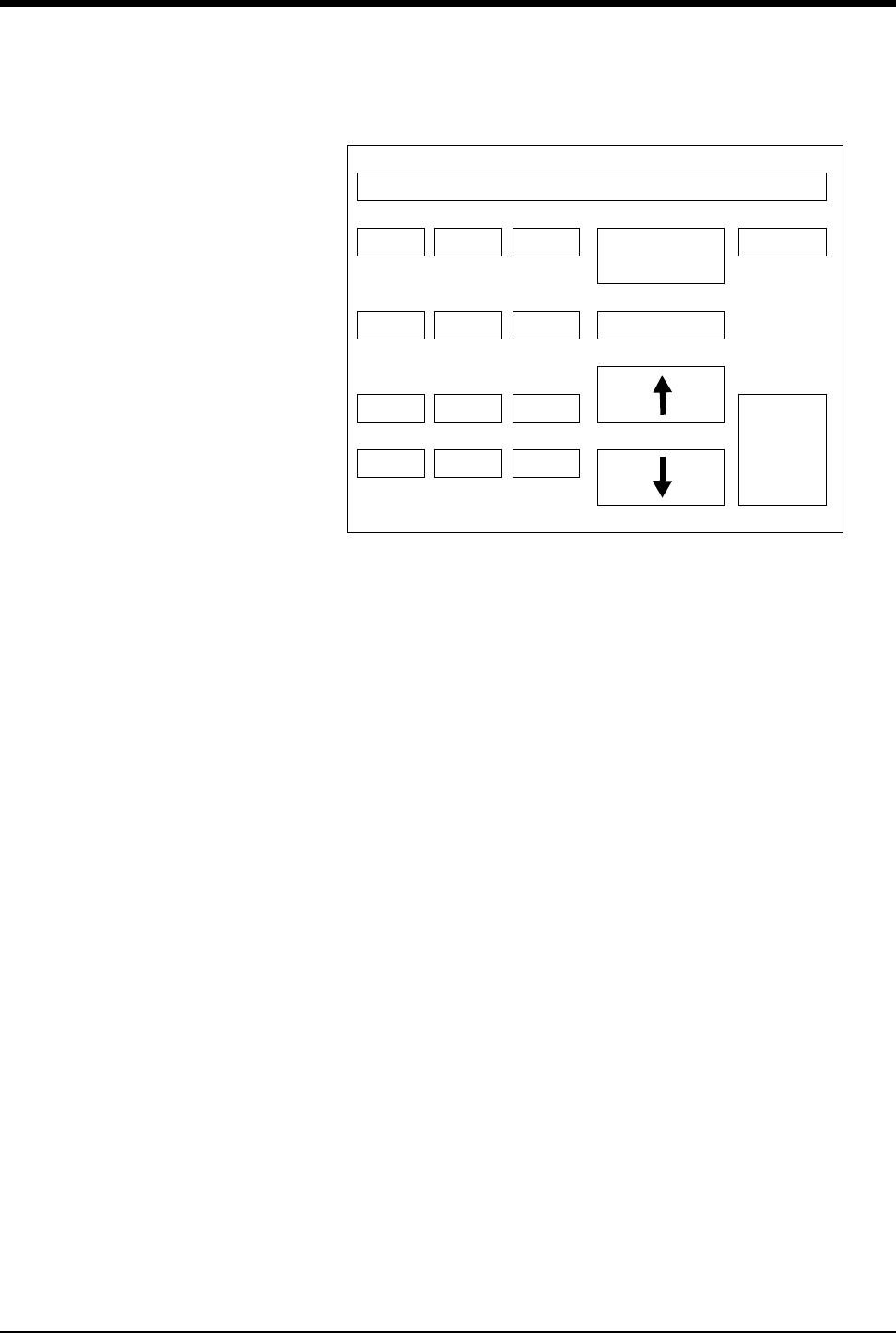
Ultraview Care Network
3-8
Figure 3-3: Ultraview 1030/1050/1500/1600 on-screen keypad
Numeric Keys — The 0 - 9 and decimal point keys allow you to enter numeric
data.
Function Keys —
↑↓ increases or decreases the displayed parameter value by 1.0, 0.1, 0.01,
or 0.001 depending on the resolution of the input value.
ENTER stores the value displayed in the top right corner of the keypad in
system memory. The ENTER key must be touched to store the value.
CLEAR sets the value in the top right corner of the keypad to 0.
RESTORE returns the previous value or displays the stored value.
REMOVE KEYPAD clears the keypad from the screen and restores the
previously displayed value.
+/- This key is disabled.
Entering Patient Date of Birth
Ultraview 1030/1050/1500/1600
To enter the patient’s date of birth, touch the DATE OF BIRTH key and enter the
month, day, and year. Touch ENTER to store the information in the monitor’s
memory.
UCW/Ultraview 1700
To enter the patient’s date of birth, use the TAB key to move to the Birthdate field
on the on-screen keyboard and enter the Day,Month, and Year. Touch ENTER
and ACCEPT to store the information in the monitor’s memory.
HT 66.9
789 REMOVE
KEYPAD
CLEAR
4 5 6 RESTORE
123
ENTER
+/- 0 .

Admit/Discharge
3-9
Entering Patient Type and Gender
To select the patient type, touch the ADULT/NEONATE key. Once the selection
has been made, it is stored in the monitor’s memory and either ADULT or
NEONATE is highlighted. If you use one patient type exclusively, your system
administrator may set the selection to that specific type.
To select the patient gender, touch the MALE/FEMALE key. Once the selection
has been made, it is stored in the monitor’s memory and either MALE or FEMALE
is highlighted.
Changing Patient Information
To alter any existing patient information, use the CHANGE DATA key. This key
does not function when there is no patient name or ID number stored in the
system.
Discharging a Patient
To clear the bedside monitor of existing patient information, touch the
DISCHARGE key. You can now purge the existing patient data.
To change patient information:
1Touch MONITOR SETUP.
2Touch ADMIT/DISCHARGE.
3a Select a subnet or a bed
(central only).
3b If you selected a subnet, then
select a bed.
4Touch CHANGE DATA.
5Make desired changes as
described under Entering New
Patient Information on page 3-4.
To discharge a patient:
1Touch MONITOR SETUP.
2Touch ADMIT/DISCHARGE.
3a Select a subnet or a bed
(central only).
3b If you selected a subnet, then
select a bed.
4Touch DISCHARGE.
5Select YES to purge the existing
data.

3-10
Admit/Discharge Troubleshooting Guide
Clinical Situation Possible Cause Solution
Patient name incorrect as
entered on keyboard menu
■Name exceeds 40 character
maximum and system has written
over some characters.
■Re-enter name using 40
characters or less.
■No patient name or ID number stored
in system.
■Enter name or ID number.
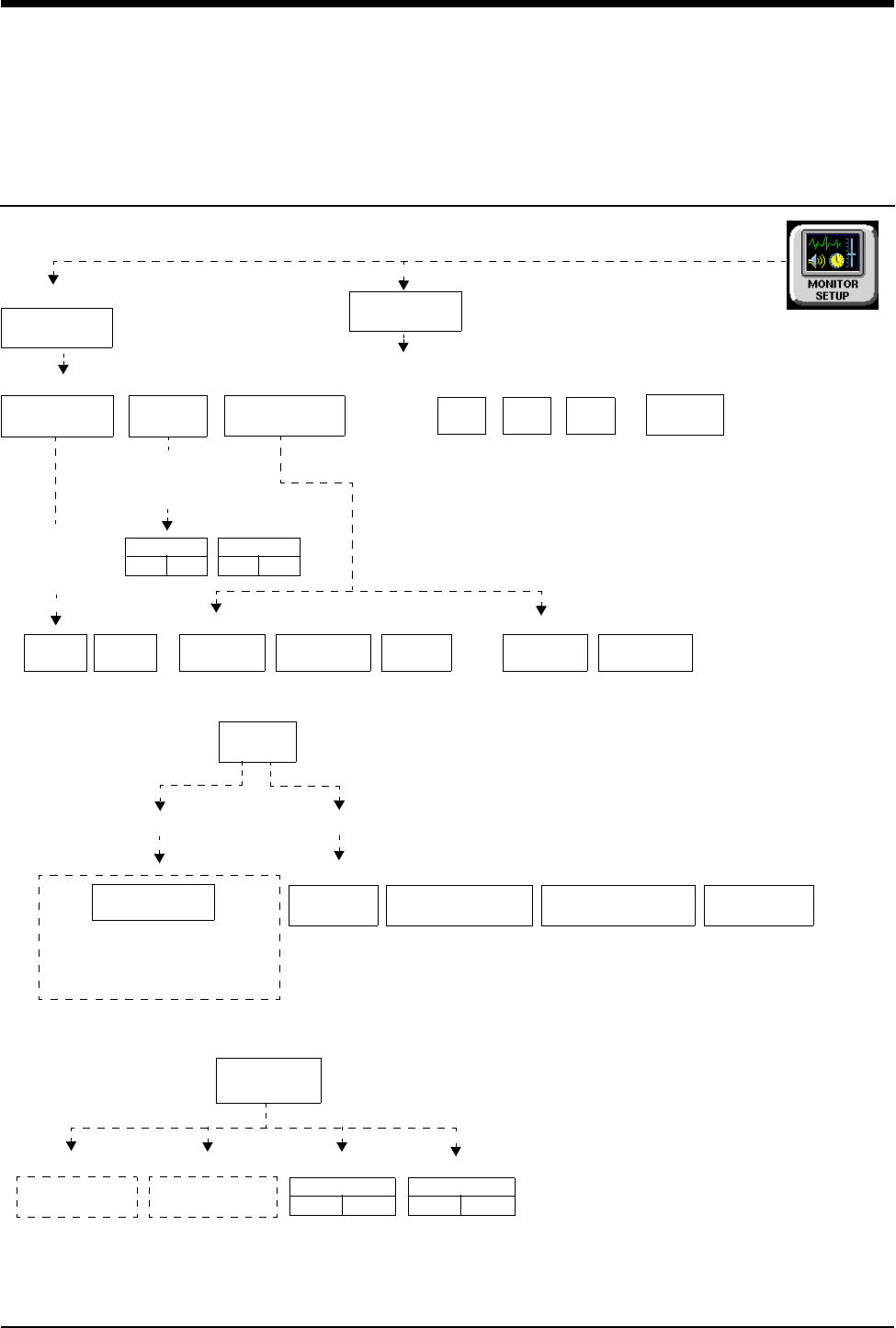
4-1
!
• Based on features purchased, more or fewer keys may appear here than on your menu screens.
Printing Directory
Directory of Keys - Monitor Setup Level
RECORDER
CONFIG.
RECORDING
DURATION
ALARM
PARAMS
RECORD
ALL
RECORD
PRESELECTED A
RECORD
PRESELECTED B
CONTINUOUS
RECORD
PRINTER
(1 - 8)
STOP
RECORDING
CONVERT TO
CONTINUOUS
To set up the printer:
To obtain recordings from the monitor:
Touch RECORD once
Touch this key, then touch
RECORDER MENU
Touch RECORD twice
the desired parameter key
(up to four), for each parameter
to be continuously recorded
PRINTER (1 - 8 ) CONTROL MENU
1 42
Number of Recorder Channels
RECORDING
DESTINATION
NETWORK BOTH
ALARM RECORDINGS TO:
THIS
MONITOR
OTHER RECORDINGS TO:
VITALS
SETUP
RECORD
PRINT
VITAL SIGNS
SYSTEM PRINTER MODULE
To control recordings from the monitor using the system printer module:
12 SEC
PRIVILEGED
ACCESS
See following pages
MONITOR SETUP
RECORDER CONFIGURATION
Select duration
of recordings
initiated from
this monitor
Select parameters
that require
alarm recording
from bed x
20 SEC
ECG
ONOFF
...
ONOFF
NETWORK
THIS
MONITOR
SLOW
ON OFF
PRINTER
ON OFF
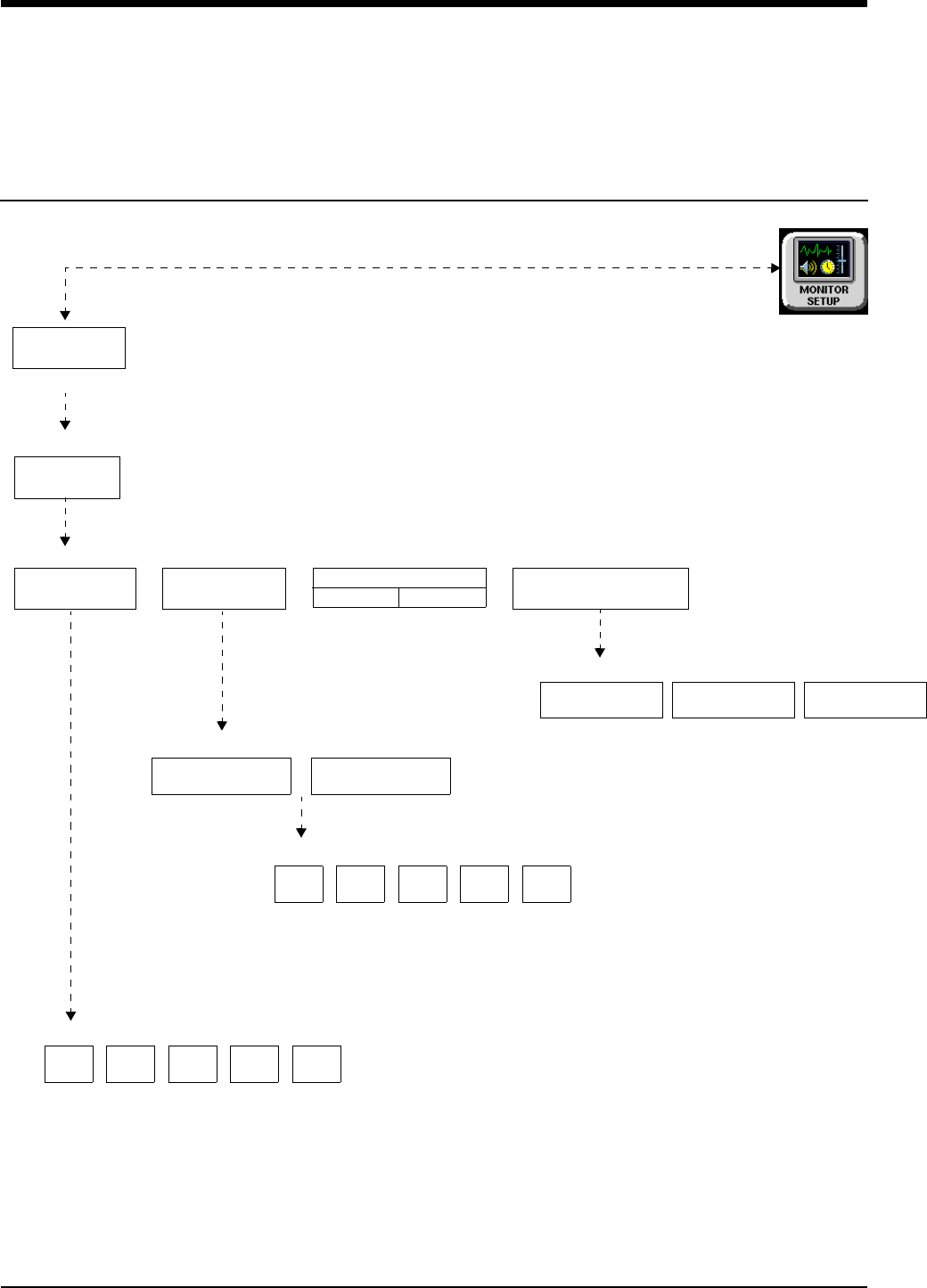
Printing Directory
!
• Based on features purchased, more or fewer keys may appear here than on your menu screens.
4-2
Directory of Keys - Biomed Level
SELECT
BIOMED LEVEL: Select Parameter
ACCESS
Enter BIOMED password
RECORDER
NAMES
RECORDER
SETUP
RECORDERS
ALARM EXTENDED
DURATION SETTING
RECORDER SETUP - Select Parameter
Select recorder name to change
Selecting a key displays keyboard for renaming printer.
RECORDER A RECORDER B
Select priority of recorder to be assigned to bed x
Select RECORDER x recorder for bed x
Laz1
PRIVILEGED
ALARM EXTENDED DURATION SETTING
SELECTION
AUTO BACKUP
0 SECONDS 6 SECONDS 12 SECONDS
Laz1
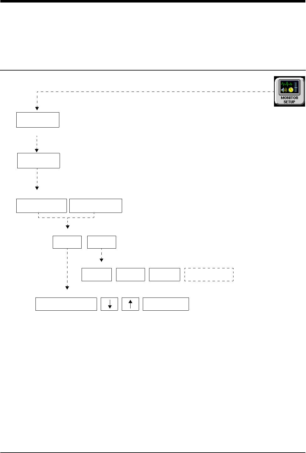
4-3
!
• Based on features purchased, more or fewer keys may appear here than on your menu screens.
Printing Directory
Directory of Keys - Clinical Level
Refer to “To obtain recordings from the monitor” and “To control recordings from the monitor using the system printer module”
PRIVILEGED
ACCESS
Enter CLINICAL password
PRESELECTED RECORDINGS - Select configuration to change
Select option to change - X: (current selection displays)
SELECT
TYPE
SELECT
BED
Select recording type - X: Beds = (current selection displays)
ALL BEDSIDE
BEDSIDE PARAM(S)
CONFIGURED
PARAMETERS
Select beds/subnets - X: (current selection displays)
ALL
SUBNETS
THIS
SUBNET
THIS
MONITOR
ALL BEDS ON
THIS MONITOR
on page 4-1 for more UCW and Ultraview 1700 keys.
PRESELECTED A PRESELECTED B
PRESELECTED
RECORDINGS


Contents
4-5
Overview . . . . . . . . . . . . . . . . . . . . . . . . . . . . . . . . . . . . . . . . . . . . . . . . . . . . . . . 5
Bedside Printer Module . . . . . . . . . . . . . . . . . . . . . . . . . . . . . . . . . . . . . . . . . . . . 6
System Printer Module . . . . . . . . . . . . . . . . . . . . . . . . . . . . . . . . . . . . . . . . . . . . 6
Ultraview 1030/1050 Monitor Printers . . . . . . . . . . . . . . . . . . . . . . . . . . . . . . . . . 7
PrintMaster . . . . . . . . . . . . . . . . . . . . . . . . . . . . . . . . . . . . . . . . . . . . . . . . . . . . . 7
Printing Priorities . . . . . . . . . . . . . . . . . . . . . . . . . . . . . . . . . . . . . . . . . . . . . . . . 11
Selecting Print Duration . . . . . . . . . . . . . . . . . . . . . . . . . . . . . . . . . . . . . . . . . . . 12
Printer Key Functions . . . . . . . . . . . . . . . . . . . . . . . . . . . . . . . . . . . . . . . . . . . . 13
Recording Alarms . . . . . . . . . . . . . . . . . . . . . . . . . . . . . . . . . . . . . . . . . . . . . . . 14
Selecting Recording Destination . . . . . . . . . . . . . . . . . . . . . . . . . . . . . . . . . . . . 14
Printing via Monitors . . . . . . . . . . . . . . . . . . . . . . . . . . . . . . . . . . . . . . . . . . . . . 14
Defining Preselected Recording Keys . . . . . . . . . . . . . . . . . . . . . . . . . . . . . . . . 16
Loading Paper . . . . . . . . . . . . . . . . . . . . . . . . . . . . . . . . . . . . . . . . . . . . . . . . . . 17
Paper Out Conditions . . . . . . . . . . . . . . . . . . . . . . . . . . . . . . . . . . . . . . . . . . . . 18
Record Vitals Report (Ultraview 1030/1050 Only) . . . . . . . . . . . . . . . . . . . . . . . 19
Printing Troubleshooting Guide . . . . . . . . . . . . . . . . . . . . . . . . . . . . . . . . . . . . . 21
Printing
Overview
This chapter documents the printing functions of the following printing
components:
• 90449 bedside printer module
• 90469 (2- and 4-channel) system printer module
• Record Vitals Report
• Ultraview 1030/1050 printer
• 90838 PrintMaster™ laser printer
The chapter reviews each printer and includes information and instructions about
its features.
Printers can provide strip chart recordings of the following:
• Automatic recordings of any parameter in an alarm condition (if configured in
the MCM and if the Record Alarms Parameters function is enabled for that
parameter).
• Parameter data such as:
- Patient name, bed name, and time and date of recording
- Vital signs, edgeprint annotation, and scaling information
- Waveform data (including timing tick marks and a grid)
- Arrhythmia/ST segments
• Non-waveform data displayed on the screen such as graphic trends, data
tables, hemodynamic calculations, and cardiac output.
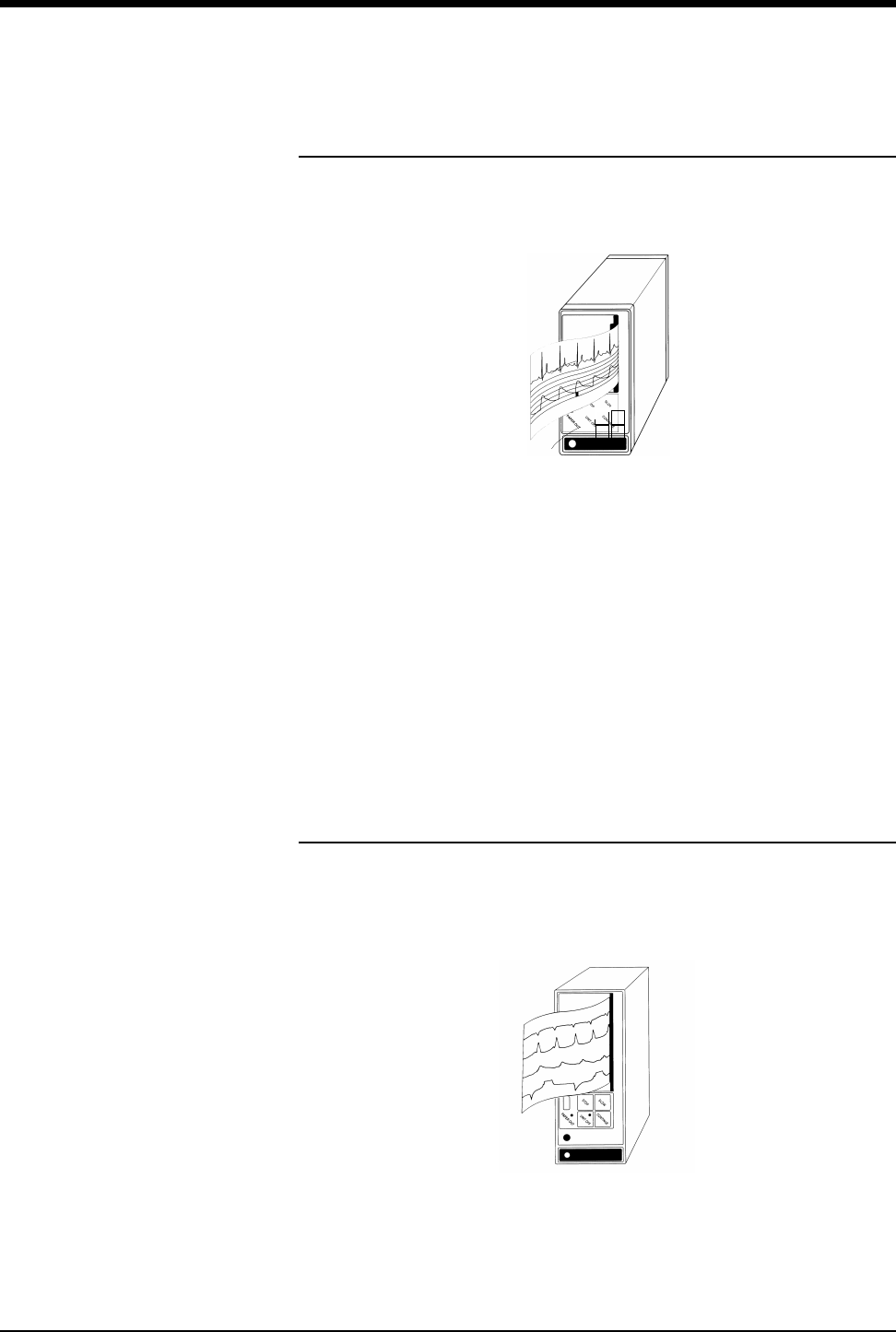
Ultraview Care Network
4-6
Bedside Printer Module
The 90449 bedside printer module is a two-channel printer that provides
automatic and manual recordings of parameter data on 50mm fanfold paper.
Figure 4-1: 90449 bedside printer module
The bedside printer module prints recordings of parameters in alarm conditions,
requested waveforms, and non-waveform data such as:
• tabular trends
• hemodynamic calculations
• drug dose calculations
• graphic trends waveform data
System Printer Module
The 90469 system printer module is a two- or four-channel printer that provides
automatic and manual recordings of parameter data on 50mm or 120mm fanfold
paper.
Figure 4-2: 90469 system printer module
!
• The bedside printer is not designed for use as a system printer
and will not function correctly if used in this manner.
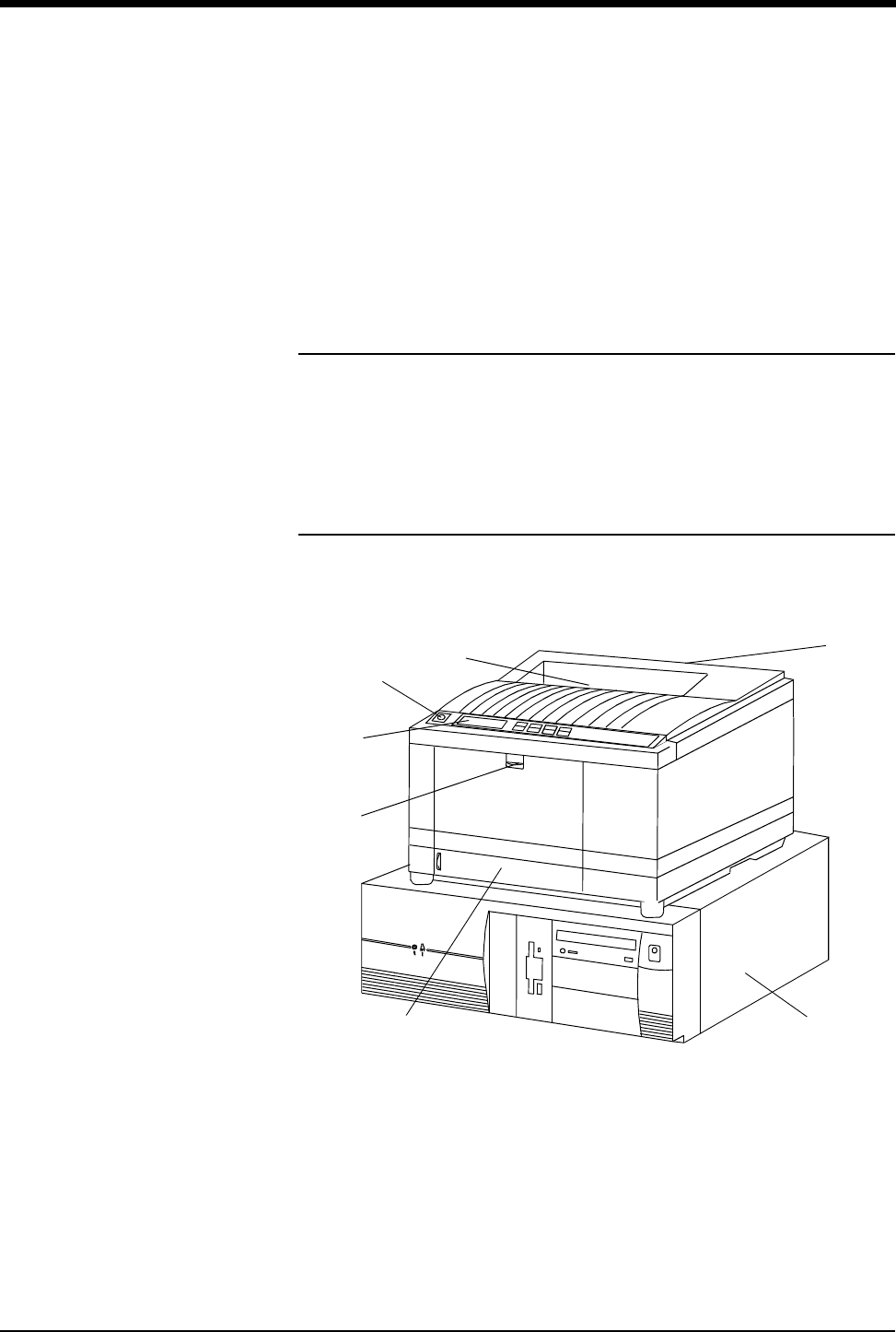
Printing
4-7
The Ultraview Care Network system printer module prints recordings of
parameters in alarm conditions, requested waveforms, and non-waveform data
such as:
• tabular trends
• hemodynamic calculations
• drug dose calculations
• graphic trends waveform data
Ultraview 1030/1050 Monitor Printers
The printers in the Ultraview 1030/1050 monitors are two-channel printers that
provide automatic and manual recordings of parameter data on 50mm roll paper.
The printers print recordings of parameters in alarm conditions, requested
waveforms, and non-waveform data.
PrintMaster
The 90838 PrintMaster is a four-channel, network printer that provides automatic
and manual recordings of parameter data on 8 1/2 x 11 or A4 paper.
Figure 4-3: PrintMaster
Display panel Central processing unit
Top cover release Paper drawer
Top printout tray Front cover release
Rear cover release

Ultraview Care Network
4-8
The PrintMaster printer functions the same as the bedside and system printer
modules in that it prints recordings of parameters in alarm conditions, requested
waveforms, and non-waveform data.
Clearing Paper Jams (PrintMaster)
If a paper jam occurs, a message will indicate the location of the jam. Once the
jam is cleared, the cover closed, and the printer warmed up, the printer will print all
the pages affected by the jam.
One of three paper jam messages may appear on the printer display:
Terminating a Print Job (PrintMaster)
To terminate an undesired multi-page print job that is currently printing, power the
printer OFF (until the front panel lights go out) then turn it back ON. This cancels
any print job in process.
Replacing the Toner Cartridge (PrintMaster)
When the TONER LOW message appears on the printer display:
1. Open the top cover.
2. Lift and pull the toner cartridge out at an angle.
3. Insert the new cartridge.
4. Close the top cover.
Table 1: PrintMaster Paper Jam Messages
PAPER INPUT JAM
1. Pull out the paper drawer.
2. Remove the sheet that did not feed.
3. Inspect remaining sheets to ensure they are not
wrinkled or stuck together.
4. Close the paper drawer.
5. Open and close the top cover to clear the paper jam
message.
PAPER FEED JAM
1. Open the top cover.
CAUTION! THE FUSING UNIT IS HOT.
2. Lift out the image drum cartridge.
3. Carefully remove the jammed paper.
4. Replace the image drum cartridge.
5. Close the top cover.
PAPER EXIT JAM
1. Open the top cover and the rear cover to release
the roller pressure.
CAUTION! THE FUSING UNIT IS HOT.
2. Pull the paper out from the rear or inside of the
printer.
3. Close the top and rear covers.

Printing
4-9
PrintMaster Display Messages
Table 2: Printer Display Messages
Message Text Reason
ON-LINE Ready to receive data.
OFF-LINE Not ready to receive data.
DATA PRESENT Print data is in buffer.
PRINTING Data is being received and printed.
POWER SAVING Power saving mode is active.
LOW TONER Toner is running out. 100 more pages can be printed when this
message is first displayed.
TONER EMPTY REPLACE TNR CART Toner cartridge is empty. Printer will stop receiving printing until
toner cartridge is replaced.
TONER SENSOR Malfunction of toner sensor is detected.
RESET Manual reset was initiated. All temporary fonts and macros are
deleted.
PRINT FONTS Font page is printing.
DRUM CLEANING Drum cleaning page is printing.
PRINT DEMO PAGE Demo page is printing.
PRINT MENU Menu page is printing.
CHANGE DRUM Drum near 90% of life. Change drum and reset drum counter.
FUSER LIFE Fuser near end of life. Contact service.
COPY nnn/mmm
Indicates number of copies printed.
nnn = page being printed.
mmm = total copies requested.
STACKER FULL
REMOVE THE PAPER Paper exit bin is full. Printing is stopped until paper is removed.
mmmmm MANUAL PAPER REQUEST
Insert requested paper. Printing is stopped until paper is
provided or RECOVER is pressed.
mmmmm = requested size.
mmmmm ttttttt PAPER REQUEST Paper size mmmmm requested at tray ttttttt. Printing is stopped
until paper is provided or RECOVER is pressed.
PAPER OUT ttttttt Paper is out at tray ttttttt. Printing is stopped until paper is
provided.
ERROR MEMORY OVERFLOW
Page data exceeds available memory. Press RECOVER to
continue. Adjust RASTER BUFFER, RECEIVE BUFFER, and/or
FONT PROTECT in menu, and resend job.
ERROR RECEIVE BUFFER OVERFLOW Received buffer overflow. Data was lost. Press RECOVER to
continue, and resend job.

Ultraview Care Network
4-10
The PrintMaster will beep every 15-seconds under the following conditions:
• Paper jam
• Missing toner cartridge
• Top cover or back door open
• Power to printer is OFF
• Power cord is disconnected
• Printer cable is disconnected
• Printer in Not Ready mode
ERROR PRINT OVERRUN
Data too complex for current RASTER BUFFER setting.
Increase RASTER BUFFER value and resend job or add
memory. Press RECOVER to continue.
ERROR HOST I/F Host interface error. Data was lost. Press RECOVER to
continue, and resend job.
CARD NOT FOUND PLEASE REINSERT Font card removed. Reinstall card. Press RECOVER to
continue, and resend job.
ERROR PAPER SIZE CHECK ttttttt Incorrect paper size detected for tray ttttttt. Provide correct
paper size and press RECOVER to continue.
PAPER INPUT JAM CHECK ttttttt Paper jammed while being supplied from tray ttttttt. Clear jam
and open/close top cover.
PAPER FEED JAM CHECK tttttttt Paper jammed during feeding from tray tttttttt. Clear jam and
open/close top cover.
PAPER EXIT JAM REMOVE THE PAPER Paper jammed during exit. Clear jam and open/close top cover.
COVER OPEN Close cover.
EEPROM RESETTING EEPROM resetting to factory defaults; returns to ON-LINE.
ERROR CARD FORMAT CHECK Installed font card has invalid data. Turn off printer to clear error.
ERROR CARD REMOVED ON-LINE Font card removed while ON-LINE. Turn off printer to clear error.
ERROR CONTROLLER nn
On -aaaaaaaa
Controller error, nn = error type. Power off printer to clear error.
If error continues, contact your Customer Service
Representative.
88888888
88888888
Displayed when power is turned on. This is done to test all LEDs
and LCD segments.
INITIALIZING Controller is being initialized at power ON.
RESET TO SAVE Press RESET to save menu changes. Menu changes cannot be
reset automatically because data is present in buffer.
Table 2: Printer Display Messages (continued)
Message Text Reason

Printing
4-11
Printing Priorities
Each Spacelabs Medical network-connected patient monitor is capable of sending
recordings to two network printers. With two printers available to monitors on the
network, printer selection rules are used to strike the best possible balance to:
• generate the most timely output of high priority recordings;
• ensure that subsequent recordings from one patient over a short time span
are processed by one printer; and
• use paper as efficiently as possible.
When the printing load is heavy, these objectives may conflict. The factors that
are taken into consideration when a print request occurs include:
• Are either of the two printers outputting, holding in memory queue, or loading
in queue a print job from this monitor?
• Are either of the printers idle?
• Is the record request a high priority request (alarm vs. manual)?
• Are either of the printers currently printing a continuous recording?
• Are either of the printers’ queues full?
• Which of the printers is the preferred size for this request
(1, 2, or 4 channels)?
At the time of a printing request, the monitor from which the request is coming
evaluates both of the available printers one at a time, leading to a score for each
of the two printers. Each printer’s evaluation passes all the way through the
priority tree from the top score to the score at the bottom of the tree. The printer
generating the highest score gets the job. If the evaluation produces the same
score for each printer, the print job is sent to the printer designated as the primary
printer for that monitor.
The printing rules mentioned work best when the two printers are sharing the
printing load. The monitor automatically determines which printer is best for each
type of recording. Another configuration designates one printer as the primary
printer and the other as the backup printer. All recordings are sent to the primary
printer unless it is unable to print for the following reasons:
• Off-line
• Out of paper
• Disconnected from network
• Powered OFF
• All print queues full
• Unable to accept recording type
If the primary printer is unable to print, the recordings are then sent to the backup
printer unless it is also unable to print for the reasons listed above.
Some networks are configured so that recordings from a given monitor are
directed to only one of the printers on the network. In this case only one printer will
be available instead of two during possible times of simultaneous multiple bed
alarms. The selection rules will not be applicable, and print performance will be
affected.

Ultraview Care Network
4-12
The following list defines recording priorities in descending order:
Highest • Alarm recording or a manual recording request via a monitor
• RECORD ALL request via a bedside monitor
• RECORD ALL request via a central monitor
• Non-waveform recordings
Lowest • All Arrhythmia/ST classes
In all network printing cases:
• High priority print jobs bump lower priority jobs. For instance, an alarm
recording will bump graphic trends to a lower position in the print queue.
• A fully loaded printer will bump graphic trends out of the queue.
• A high priority request erases as many lower priority requests as needed to
make room for the data it contains.
Selecting Print Duration
Waveform Data
In the absence of an alarm condition, the print request origin determines the
length of time that waveform data (ECG, ART, RESP, etc.) is recorded.
Recordings requested via the monitor are either 12- or 20-seconds in duration.
This is selectable via the RECORDING DURATION key. Recordings start with a
few seconds of data received just prior to the print request, followed by real-time
data.
Non-Waveform Data
The length of time the printer requires to record non-waveform data, such as
graphs and data tables, depends on the complexity of the data and cannot be
pre-determined.
!
• A status message is not displayed when a print request
replacement occurs.
!
• The RECORDING DURATION key will not display if the
recording duration has been preset by your system
administrator.
To select print duration from the
monitor:
1Touch MONITOR SETUP.
2Touch RECORDER CONFIG.
3Touch RECORDING
DURATION to change length of
time for printing.

Printing
4-13
Printer Key Functions
Ultraview 1030/1050 Monitor, Bedside, and System
Printer Modules
Printer control keys for the bedside and system printer modules are located on the
module front. The printers can also be controlled by keys on the monitor itself.
Table 3: Key Descriptions
Key Function
SLOW
ON/OFF
Changes the print speed of waveform recordings to
6.25mm/second. Pressing SLOW a second time returns the
printer to the current system sweep speed. SLOW has no
effect on the print speed of non-waveform recordings (data
tables, graphics, etc.).
CONTINUE
• When the printer is off-line, press this key to feed roll
paper at 25mm/second or to feed one sheet of perforated
paper through printer module.
• When the printer is on-line and currently printing a 12- or
20-second waveform recording, press CONTINUE to
convert to a continuous recording. If you press
CONTINUE, the 12- or 20-second recording completes,
followed by a horizontal line, and then the current data.
The horizontal line appears even on recordings that are
not in a queue, but are the only request.
STOP
RECORDING
• Stops any printing currently in progress and moves to the
next print request in the queue.
• Stops any roll paper advance currently in progress.
PRINTER
ON/OFF
Takes the printer off-line without turning the power OFF.
Alarms and print requests are now ignored. An LED (located
either in the key or on the front panel of system printer)
illuminates when this function is selected.
To access printer control keys
from the monitor:
1Touch NORMAL SCREEN.
2Touch PRINTER CONTROLS.
3Select the desired key.

Ultraview Care Network
4-14
Recording Alarms
An alarm recording may be triggered whenever a parameter enters an alarm
condition. Recordings in the process of printing cannot be interrupted or delayed
by a new alarm condition.
Selecting Recording Destination
The RECORDING DESTINATION menu contains keys that direct alarm
recordings to a bedside recorder, a network printer, or both. All other recordings
may be directed only to a bedside printer or a network printer, but not both.
Alarm recordings begin with several seconds of pre-alarm waveform data and
continue for as long as the alarm condition exists (a minimum of 12-seconds).
Printing via Monitors
Non-Waveform Data
Whenever you display non-waveform data on either the central or bedside
monitors, a PRINT key displays. The RECORD key is not functional for printing
non-waveform data. As a result, non-waveform data must be displayed before it
can be recorded.
Non-waveform data usually occupies a minimum of two slots in the printer’s queue
due to the volume of information being sent. This means that a single non-
waveform recording may take up as much room on the strip chart as two
simultaneous waveform recordings.
If the data cannot fit on the strip at one time, it is separated horizontally, printing
first the top half and then the bottom half of the data.
!
• Parameter alarm recordings can be set to OFF so that a printer
will not respond to an alarm condition (the alarm tone and
accompanying alarm message are unaffected). Refer to
Automatic Recording of an Alarm on page 2-10 for more details.
!
• 12-lead ECG reports will always print to the 90838 printer, if
available, regardless of the destination settings for the
recording.
To select parameters for alarm
recording and generate
automatic recordings on a
bedside recorder:
1Touch MONITOR SETUP.
2Touch RECORDER CONFIG.
3Select RECORDING
DESTINATION.
4Select a destination for the
alarm recording.
5Touch PREVIOUS MENU.
6Touch ALARM PARAMS.
7Select parameter key(s) ON to
initiate a recording in case of
alarm. If the parameter key is
OFF, no alarm recording is
produced for that parameter in
an alarm condition.
To start a manual recording via
the monitor:
1Touch RECORD.
2Touch up to four flashing
parameter keys.
3a Touch CANCEL RECORD
SELECTION(S) to terminate.
-OR-
3b Touch STOP RECORDING in
the PRINTER CONTROL
menu to terminate.

Printing
4-15
Waveform Data
Waveform data is recorded using the RECORD key on the monitor.
Each time you touch RECORD on the monitor, the CONTINUOUS RECORD key
displays and waveform parameter keys flash for up to 4-seconds. You must make
your key selection within this four-second window. This window stays open for an
additional 2- to 4-seconds each time a key is selected. Once the parameter keys
stop flashing, any waveforms that have been selected are automatically sent to
the printer for recording.
Touch the RECORD key twice to display the Recording menu. From the
Recording menu you can:
• Record all parameters currently on this screen by touching RECORD ALL.
• Initiate a preselected group of recordings by touching PRESELECTED A or
PRESELECTED B.
• Select PRINT VITAL SIGNS to manually print the vital signs you have
selected (refer to Record Vitals Report (Ultraview 1030/1050 Only) on page
4-19 for more information).
RECORD ALL and PRESELECTED A OR B recordings are 8-seconds in
duration.
Group Recordings
The printers record all the requested parameters on one patient before beginning
on the parameters of the next patient. Under no circumstances will the printer
combine the parameters of different patients onto the same strip chart.
Recordings in the process of being printed cannot be interrupted or delayed by
additional print requests.
!
• Requests for recording waveform data are limited to only those
waveform parameters that are currently displayed on the
screen (except ECG where all leads print).
• If a parameter menu is left on the screen, the CONTINUOUS
RECORD key is not displayed.
To print group recordings via the
monitor:
1Touch RECORD twice.
2a Touch RECORD ALL.
-OR-
2b Touch RECORD
PRESELECTED A or B.
To start a continuous recording
via the monitor:
1Touch RECORD.
2Touch CONTINUOUS
RECORD, then touch the
desired parameter key (up to
four, for each parameter to be
continuously recorded.
3Touch CANCEL RECORD
SELECTION to restart the
selection process.
To stop a continuous recording
via the monitor:
1Touch RECORD.
2a Touch STOP CONT.
RECORD.
-OR-
2b Touch STOP RECORDING in
PRINTER CONTROLS.

Ultraview Care Network
4-16
Defining Preselected Recording Keys
The Preselected Recordings function enables you to define which beds and
parameters will be automatically recorded. The preselected group is established
by the system administrator. For UCW and Ultraview 1700 monitors this is set up
through the Clinical level of the Privileged Access menu.
To define the PRESELECTED A
and B parameters (UCW and
Ultraview 1700):
1Touch MONITOR SETUP.
2Touch PRIVILEGED ACCESS.
3Enter Clinical password.
4Touch PRESELECTED
RECORDINGS.
5Touch key to be defined
(A or B).
6Touch SELECT TYPE.
7a Touch FIRST 2 BEDSIDE
PARAM(S) and use arrow keys
to cycle through parameter
selections: ALL BEDSIDE
PARAM(S) or FIRST n
BEDSIDE PARAM(S)
(where n is 1, 2, 4 or 8).
-OR-
7b Touch CONFIGURED
PARAMETERS and toggle
desired parameters ON or
OFF.
8Touch PREVIOUS menu twice
to define the remaining
PRESELECTED key.
To define the PRESELECTED A
and B beds (UCW and Ultraview
1700):
1Touch MONITOR SETUP.
2Touch PRIVILEGED ACCESS.
3Enter Clinical password.
4Touch PRESELECTED
RECORDINGS.
5Touch key to be defined
(A or B).
6Touch SELECT BEDS.
7a Select ALL SUBNETS.
-OR-
7b Select THIS SUBNET.
-OR-
7c Select THIS MONITOR.
8Touch PREVIOUS menu twice
to define the remaining
PRESELECTED key.
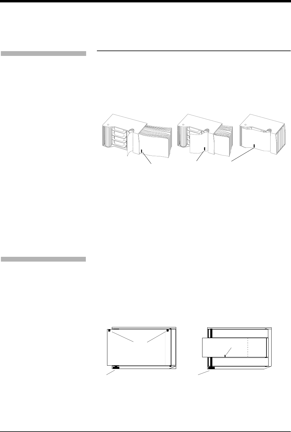
Printing
4-17
Loading Paper
Bedside Printer Module
The small black rectangular cue mark on the bedside printer paper must face out
and be at the bottom of the tray when loading paper into the tray.
Figure 4-4: Bedside printer module paper tray
Each recording starts at the Z-fold perforation and blank sheets are not placed
between successive print requests.
System Printer Module
The system printer module has a slide-out plastic tray that accepts packets of
Z-fold paper. The 2-channel printer uses 50mm wide by 27m long paper. The
4-channel printer uses 120mm wide by 45.7m long paper. Each sheet has a small
black rectangular cue mark located along the edge used to load the paper into the
tray.
Figure 4-5: System printer module paper trays (top view)
To load paper in a bedside
printer module (2-channel only):
1Press eject button next to
PAPER OUT light.
2Withdraw plastic paper tray.
3Discard old cardboard retainer
inside tray.
4Remove label from new paper
but keep cardboard retainer in
place around one end.
5Start inserting paper into tray,
beginning with cardboard
retainer end.
6With paper halfway into tray, lift
up spring-loaded roller.
7Bring out top fold of paper from
under top end of cardboard
retainer.
8Bring top fold over top of spring-
loaded roller.
9Release spring-loaded roller
onto remainder of paper.
10 Insert stack fully.
11 Unfold paper and position over
top of black roller at end of tray.
12 Slide tray completely back into
printer module.
Note orientation of small cue mark
To load paper in a system printer
module (2- or 4-channel):
1Press eject button next to
PAPER OUT light.
2Withdraw plastic paper tray.
3Discard old cardboard retainer
inside tray (2-channel only).
4Remove label from new paper
but keep cardboard retainer in
place around one end
(2-channel only).
5Discard 4-channel container.
6Start inserting paper into tray,
beginning with cardboard
retainer end (2-channel only).
7Make sure black squares are in
the top left corner of the pages
(4-channel).
8Insert stack fully.
9Unfold paper and position over
top of black roller at end of tray.
10 Slide tray completely back into
printer module.
4-channel 2-channel
paper roller paper roller
cue mark cue mark
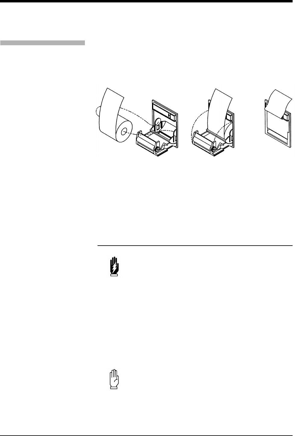
Ultraview Care Network
4-18
Ultraview 1030/1050 Printers
The Ultraview 1030/1050 monitor’s printer uses 50mm wide by 30m long rolls of
thermal paper. The printer has an automatic self-feed mechanism for threading
the paper through the rollers.
Figure 4-6: Loading printer paper
PrintMaster
The PrintMaster printer has a slide-out paper drawer that accepts up to 500 pages
of letter or A4-sized copy paper. Slide the drawer out of the printer, place the
paper (according to orientation) into the cassette, and place the cassette back into
the printer.
Paper Out Conditions
All printers signal a paper out condition by periodically sounding a tone. The
PrintMaster will beep every 15-seconds when there is no paper in the cassette, or
the cassette is not loaded. In addition, the PrintMaster and the bedside printer
module flash the PAPER OUT light, while the 2-channel and 4-channel system
printer modules display a LOCAL PRINTER PAPER OUT message. On the
Ultraview 1030/1050 monitor’s printer, the PAPER OUT tone does not sound if the
local alarm tone key is set to OFF.
After reloading paper in the system printer module, the paper-feed mechanism
ejects a sheet to verify proper paper feeding. For the paper-feed mechanism to
work, you must leave the printer power ON while you are loading paper.
WARNING:
• While printers are off-line, or out of paper, they will ignore
any new alarm that would normally start a recording, and
no alarm or requested recordings will go into a queue.
CAUTION:
• Removing a bedside or system printer module from the
monitor to load paper causes an immediate loss of
pending print requests.
To load paper in the Ultraview
1030/1050 printer:
1Press release button on door.
2Open paper tray door all the
way.
3Snap new roll into place.
4Pull out 6 to 12 inches of paper.
5Close door.

Printing
4-19
Record Vitals Report
(Ultraview 1030/1050 Only)
The Record Vitals Report:
• provides manual recordings of parameter data on 50mm roll paper
• only prints to the monitor’s internal recorder
Figure 4-7: Vitals Setup menu keys
Data Interval
You may choose a time interval ranging from 1-minute to 60-minutes, specifically,
1-, 2-, 3-, 5-, 10-, 15-, 30-, and 60-minute intervals. You can also select NIBP
ON/OFF and other parameter data from that reading time. If you select NIBP ON,
you are not required to select an interval. NIBP readings appear in the report
based on the time that you take the readings. If you do not choose an interval or
NIBP ON before printing, the message VITALS REPORT ERROR prints.
Start Time
You may print vital sign measurements ranging from those taken in the past hour
to those taken in the last 24-hours, specifically, 1-, 2-, 4-, 8-, 12-, and 24-hours.
Select Parameters
You may choose the parameters you wish to have included in the report. If you
choose a vital sign for which no data is available, ??? appears on the report.
The following is an example of a vitals report. A blank space to enter notes is
standard in every report.
Figure 4-8: Vitals report
Time HR BPM Resp RPM Temp 1 C Notes
07:50 74 18 37.8
07:52 74 18 37.8
07:54 54 13 37.8
07:56 54 13 37.8
To define the details of a report:
1Touch MONITOR SETUP.
2Touch RECORDER CONFIG.
3Touch VITALS SETUP.
4Touch DATA INTERVAL and
select an interval for report
history.
5Touch PREVIOUS MENU.
6Touch START TIME and select
a time period for report history.
7Touch PREVIOUS MENU.
8Touch SELECT
PARAMETERS and select the
parameters you wish to include
in the report.
9Touch PREVIOUS MENU.
START
TIME
PRINT
VITAL SIGNS
Configure parameters or start vitals recording
SELECT
VITALS
SETUP
DATA
INTERVAL PARAMETERS

Ultraview Care Network
4-20
Print Vital Signs
To print the report, touch PRINT VITAL SIGNS or touch RECORD twice and then
touch PRINT VITAL SIGNS.
!
• Be sure to choose the data interval, the start time, and the
parameters you wish to include on the report before printing.
To print a manual report with the
Record Vitals Report option:
1Touch VITALS SETUP, PRINT
VITAL SIGNS.
-OR-
2Touch RECORD twice and
touch PRINT VITAL SIGNS.

4-21
Printing Troubleshooting Guide
Clinical Situation Possible Cause Solution
Printer displays PAPER
OUT message
■Printer is out of paper. ■Load paper (refer to Loading Paper
on page 4-17).
■Printer door is open.
■Paper was loaded improperly.
Printer fails to print self-
test strip
■Failed internal diagnostics. ■Notify qualified service person.
Message UNABLE TO
RECORD THE
REQUESTED CHANNEL is
displayed
■Printer not active.
■Printer not selected by a system
administrator.
■Printer is out of paper.
■Toggle PRINTER ON/OFF key.
■Check with your hospital biomed or
system administrator.
■Load paper.
CONTINUOUS RECORD
key not displayed
■Menu is at the bottom of the screen. ■Touch NORMAL SCREEN, then
RECORD.

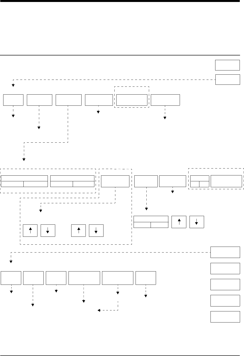
5-1
!
• Based on features purchased, more or fewer keys may appear here than on your menu screens.
Bedside/Transport Monitors
Directory
Directory of Keys
ADMIT/
DISCHARGE
TONES MONITOR
CONFIG.
RECORDER
CONFIG.
MONITOR SETUP
MONITOR CONFIGURATION
Refer to System Introduction chapter
Refer to
SPECIAL FUNCTIONS
ENERGY SAVING MODE
ON
REMOTE
VIEW
PARAMETER
CONFIG
SCREEN BRIGHTNESS
NORMAL
SPECIAL
FUNCTIONS
Refer to Setting up Priorities
and Colors in this chapter
BRIGHTNESS
CONTRAST
REMOTE
TRENDS/CALCS
ALARM
WATCH
RV/AW
OFF
LOCAL
TRENDS/CALCS
PRIVILEGED
ACCESS
TONE RESET
ALM SUSPEND
NORMAL
SCREEN
RECORD
PREVIOUS
MENU
MINOR
GRATICULE
Refer to
Alarms chapter
Refer to
Alarms chapter
Refer to
System
Introduction
chapter Refer to
Trends or
Calcs chapter
Select bed
MINOR GRAT
ON OFF
MINOR GRATICULE - 2 divisions
MONITOR SETUP: DISPLAY BRIGHTNESS AND CONTRAST
BRIGHTNESS CONTRAST
UCW, Ultraview 1500, 1600, and 1700
OFF DIM
Refer to
Alarms chapter
Refer to
Admit chapter
Printing chapter
OUTBOUND
PARAMETERS
DATA
LOGGER
Refer to
Refer to
Refer to
System Introduction
chapter
Printing chapter
Alarms chapter
Refer to
Patient Data Logger
chapter
Ultraview 1030 and 1050 only
MONITOR
SETUP
HELP
DC Power AC Power
Refer to the next page
CLOCK
ON OFF
ACTIVATE
SCREEN SAVER
UCW and Ultraview 1700 only
Ultraview 1030/1050
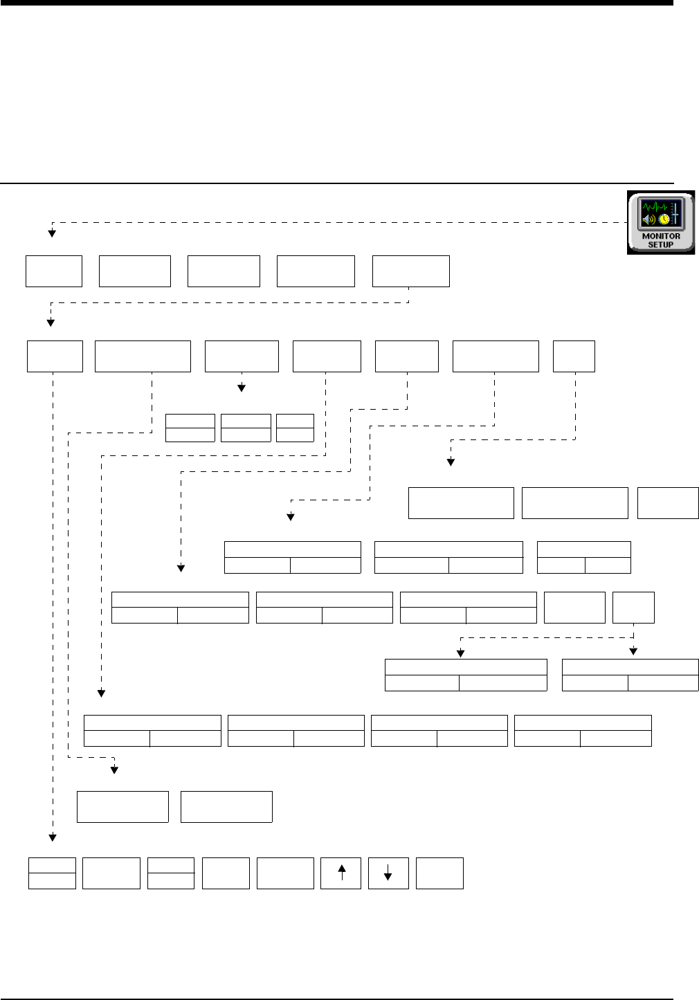
Bedside/Transport Monitors
Directory
!
• Based on features purchased, more or fewer keys may appear here than on your menu screens.
5-2
Directory of Keys - UCW and Ultraview 1700
(Privileged Access)
ROTATE ALARM WATCH
ALARM WATCH SETUP - Select parameter to change
PRESELECTED RECORDINGS - Select configuration to change
RESET
MONITOR
CHANGE CLINICAL
PASSWORD
CLINICAL LEVEL - Select Parameter
UNITS OF
MEASURE
USER
ACCESS
ALARM
SETUP
CLINICAL LEVEL - Select Parameter
TIME/
DATE
TIME
DATE 24 HOUR HOURS ENTER
USER ACCESS - Enable user access to functions
PRESELECTED
A
PRESELECTED
B
ALARM WATCH ROTATION
PRIORITY
MINUTES
mmHg
kPa
inches
cm
lb
kg
MONITOR SETUP - Time/Date 10:06 AM/PM
ROTATION TIME
15 S 30 SSIMPLEON OFF
AM
PM
ALARM WATCH
SETUP
Restart monitor after selecting
units of measurement
Enter clinical level password
ALARM SETUP - Select parameter
ADMIT/
DISCHARGE
TONES MONITOR
CONFIG.
RECORDER
CONFIG.
MONITOR SETUP
PRIVILEGED
ACCESS
PRESELECTED
RECORDINGS MORE
REMOTE ACCESS
ON OFF
ALARM SUSPEND
ON OFF
TREND SUSPEND
ON OFF
ALARM
RELAY MORE
QRS/SPO2 TONE ENABLE
ALWAYS DURING ALARM
ALARM WATCH TONE
SINGLE TRIPLE
PATIENT TY PE
ON OFF
PARAMETER CONFIG
ON OFF
RECORDING DURATION
ON OFF
SUBNET ACCESS
ON OFF
REMOTE KEYPAD
STATION ADDRESS

Contents
5-3
Overview . . . . . . . . . . . . . . . . . . . . . . . . . . . . . . . . . . . . . . . . . . . . . . . . . . . . . . . 3
Display Detail. . . . . . . . . . . . . . . . . . . . . . . . . . . . . . . . . . . . . . . . . . . . . . . . . . . . 4
Identifying Special Applications . . . . . . . . . . . . . . . . . . . . . . . . . . . . . . . . . . . . . . 4
Bedside and Transport Monitor Features . . . . . . . . . . . . . . . . . . . . . . . . . . . . . . 5
Setting Up Priorities and Colors. . . . . . . . . . . . . . . . . . . . . . . . . . . . . . . . . . . . . . 7
Data Shuttle Option . . . . . . . . . . . . . . . . . . . . . . . . . . . . . . . . . . . . . . . . . . . . . . 10
Ultraview 1030/1050 Batteries . . . . . . . . . . . . . . . . . . . . . . . . . . . . . . . . . . . . . . 13
Wireless Network Interface . . . . . . . . . . . . . . . . . . . . . . . . . . . . . . . . . . . . . . . . 15
Outbound Parameters Menu . . . . . . . . . . . . . . . . . . . . . . . . . . . . . . . . . . . . . . . 15
Ultraview 1030/1050 Connections . . . . . . . . . . . . . . . . . . . . . . . . . . . . . . . . . . . 18
Ultraview 1030/1050 with Capnography (Option G or H) . . . . . . . . . . . . . . . . . 21
Maternal Obstetrical Monitor - 94000 . . . . . . . . . . . . . . . . . . . . . . . . . . . . . . . . 22
Bedside/Transport Monitor Troubleshooting Guide . . . . . . . . . . . . . . . . . . . . . . 27
Bedside/Transport Monitors
Overview
This chapter describes the functions and features of bedside and transport
monitors. Refer to the Bedside/Transport Monitors Directory on page 5-1 for help
in locating functions not described in this chapter.
The Ultraview Care Network family of monitors and modules have built-in error
detection and recovery circuitry. This circuitry, together with special software,
enables the monitor to re-initialize and continue to function if an error occurs.
When the system detects an error that cannot be corrected through other means,
the bedside monitor re-initializes or resets (blanks). Normally, a reset involves
very little loss of patient monitoring time (approximately 5-seconds) and, with few
exceptions, all operator set inputs (alarm limits, pressure labels, transducer
offsets, etc.) are retained. The entire process of restoring the bedside monitor
following a reset, takes approximately 20-seconds, depending upon the number of
parameters being monitored.
In some cases, stored trend data will be lost when the monitor resets. If this
occurs, the lost data may indicate a hardware condition that requires corrective
action. The system will then initiate the start-up diagnostics to check the monitor’s
operation and fully recover the data. This process takes approximately
10-seconds longer.
If a bedside monitor resets, the bedside monitor displays CHECK SETUP in the
ECG zone to alert you to check all limits and values and ensure that the monitor
has restored all preset values. (Refer to Power Failure on page 1-4 for more
information.) This also occurs when the monitor is turned ON or when an ECG
module has been inserted. Your system administrator may disable the CHECK
SETUP feature.
WARNING:
• Due to the potential for electromagnetic interference,
portable communication transmitters and cellular phones
should not be operated within 3.5 feet (1.07 meters) of the
patient, patient leads, or associated patient monitoring
equipment.
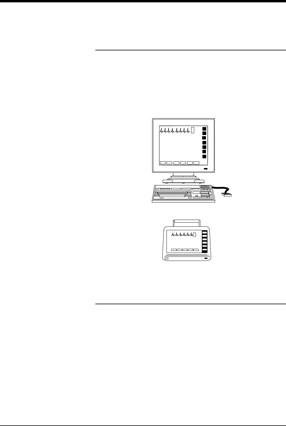
Ultraview Care Network
5-4
Display Detail
All monitoring data originates at the bedside. Parameter modules plug into the
monitor itself or into a remote module housing to obtain patient information,
including waveforms and numeric displays.
The bedside screen may (optionally) display up to eight full waveform zones. If
more than eight zones are used, zones 9 through 24 appear at the bottom of the
screen as numeric values. When you activate a numeric value key, that parameter
is displayed in the lowest priority display zone.
Figure 5-1: Bedside and transport monitors
Identifying Special Applications
If your monitor has access to Special Applications, additional keys identifying
those functions appear in the Special Functions menu. Touch the SPECIAL
FUNCTIONS key to access the applications.
Special applications include:
• Patient Data Logger (refer to Patient Data Logger on page 29-3)
• Dynamic Network Access (DNA) (refer to DNA on page 30-3)
(UCW and Ultraview 1700 only)
UCW/Ultraview 1500/1600/1700
Ultraview 1030/1050

Bedside/Transport Monitors
5-5
Bedside and Transport Monitor Features
Adjusting Screen Brightness and Contrast
Using the Monitor Setup menu you may increase or decrease the monitors’
screen contrast and brightness.
Ultraview 1030/1050 monitors contain a SCREEN BRIGHTNESS key for monitors
operating on AC power enabling you to set the screen to NORMAL or DIM.
Setting the screen to DIM also enables the power saving features such as shutting
off the LEDs and disabling the mouse and keyboard. The screen will also dim
approximately 30-seconds after the last time a key is touched or after the final
alarm ends. Ultraview 1030/1050 monitors operating on DC (battery) power
contain an ENERGY SAVING MODE ON/OFF key that enables and disables the
power saving features.
Setting QRS Tones
Your monitor can be configured to sound a tone whenever an R-wave (QRS tone)
or SpO2 pulse (SpO2 tone) is detected. The pitch of the QRS tone can be
modulated with the current SpO2value. Refer to Adjusting Tones on page 8-16
and Adjusting Tone Volume on page 14-8 for more information.
Your monitor has two options for how the QRS or SpO2tone sounds if it has been
enabled via either parameter’s TONE ON/OFF key. Your monitor can be
configured to always sound this tone (default setting) or to only sound this tone
when an alarm is occurring.
On UCW and Ultraview 1700 monitors, this selection is available to any user with
the Clinical level of “privileged access.” On Ultraview 1030, 1050, 1500, and 1600
monitors, this selection is only available to your system administrator.
Using Scaled Displays
Bedside monitors display up to four scaled pressures simultaneously.
Monitors optionally display minor graticule lines that may be adjusted. Minor
graticules are small dashed line segments that appear between the full scale
graticule lines.
To adjust screen clarity:
1Touch MONITOR SETUP.
2Touch MONITOR CONFIG.
3a Touch BRIGHTNESS.
-OR-
3b Touch CONTRAST.
-OR-
3c Touch
BRIGHTNESS/CONTRAST
(for Ultraview 1500 only).
4Use arrow keys to adjust.
To set the QRS tones (UCW and
Ultraview 1700):
1Touch MONITOR SETUP.
2Touch PRIVILEGED ACCESS.
3Enter Clinical password.
4Touch ALARM SETUP.
5Touch MORE.
6Select QRS/SPO2 TONE
ENABLE ALWAYS or
QRS/SPO2 TONE ENABLE
DURING ALARM.
To adjust the scaled display:
1Touch MONITOR SETUP.
2Touch MONITOR CONFIG.
3Touch MINOR GRATICULE.
4Select MINOR GRATICULE
ON.
5Use arrow keys to adjust.
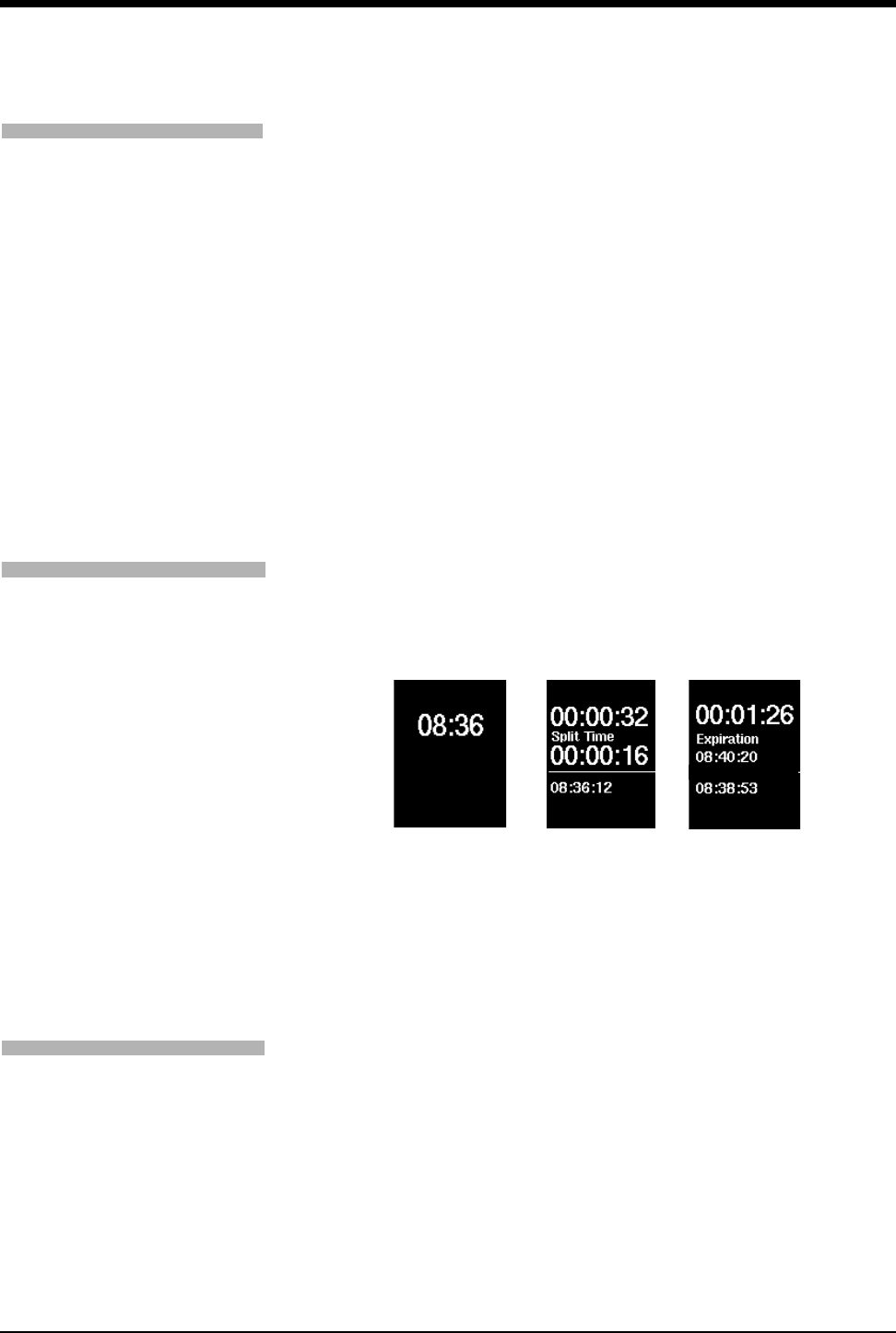
Ultraview Care Network
5-6
Setting the Time and Date
The TIME/DATE key controls both the time and date menus. The current time or
date displays above the menu.
The time displays in either 12- or 24-hour format. Network monitors display the
network time; standalone monitors display the internal system time.
Touch ENTER to make the time/date change permanent in the system.
Using the System Clock
A system clock can be continually displayed in the lower right corner of the
screen. The clock feature may also be used as a stopwatch or timer.
Figure 5-2: Clock display formats
Activating the Screen Saver
Activating the screen saver blanks the screen (displaying only the Spacelabs
Medical logo). You may also disable the screen saver by touching the screen,
clicking (or dragging) the mouse, or pressing any key on the keyboard.
!
• Setting the time on any networked monitor sets the time for all
monitors on that network.
!
• The digital clock is available for all monitors.
• The stopwatch and timer are only available for the UCW and
Ultraview 1700.
!
• The screen will automatically be restored by an incoming alarm
condition.
• This feature is only available for the UCW and Ultraview 1700.
To change the network or
internal system time and date
(UCW and Ultraview 1700 only):
1Touch MONITOR SETUP.
2Touch PRIVILEGED ACCESS.
3Enter Clinical password.
4Touch TIME/DATE.
5a Select TIME.
-OR-
5b Select DATE.
6a Select 24-HOURS or AM/PM
(12-hour).
-OR-
6b Select MONTH, DAY, and
YEAR.
7Use arrow keys to set time or
date.
8Touch ENTER.
To access the clock menu:
1Touch MONITOR SETUP.
2Touch MONITOR
CONFIGURATION.
3Select CLOCK ON.
4Touch the clock that appears in
the lower right of the screen.
5Select DIGITAL,
STOPWATCH, or TIMER.
digital timer
02 JUN 03 02 JUN 03 02 JUN 03
Elapsed Remaining
stopwatch
To activate the screen saver:
1Touch MONITOR SETUP.
2Touch MONITOR CONFIG.
3Touch ACTIVATE SCREEN
SAVER.

Bedside/Transport Monitors
5-7
Setting Up Priorities and Colors
Table 1 lists default priorities and colors for each screen parameter.
Table 1: Parameter Priorities and Colors
Channel
Type Name Priority Color
ECG1 Electrocardiogram (first lead) 1 Green
ECG2 Electrocardiogram (second lead) 2 Green
RESP Respiration 3 Cyan
VARI Varitrend 4 White
ART Arterial Pressure 5 Red
UA Umbilical Artery Pressure 6 Red
PA Pulmonary Arterial Pressure 7 Yellow
UV Umbilical Vein Pressure 8 Blue
CVP Central Venous Pressure 9 Blue
RAP Right Atrial Pressure 10 Blue
ICP Intracranial Pressure 11 Magenta
LAP Left Atrial Pressure 12 Red
PRS Other Pressure (general) 13 Magenta
UNLP Unlabeled Pressure 14 Blue
EtCO2End Tidal CO2 (Capnography) 15 White
SpO2 (SaO2) Pulse Oximetry (O2 Saturation) 16 Green
NIBP Noninvasive Blood Pressure 17 Red
SvO2Venous O2 Saturation 18 Magenta
TCP Partial Pressure of Transcutaneous O219 White
EEG Electroencephalogram 20 Blue
GAS Gas Analyzer Flexport ® Interface 21 White
CO Cardiac Output 22 Magenta
TEMP Temperature 23 White
INCUB
WARMR Incubator/Warmer 24 White
PO + ET SpO2 and EtCO2 Flexport Interface 25 White
IV Infusion Flexport Interface 26 White
VENT Ventilator Flexport Interface 27 White
OTHER 28 White
To change a parameter priority
or color:
1Touch MONITOR SETUP.
2Touch MONITOR CONFIG.
3Touch PARAMETER CONFIG.
4Select a parameter.
5Select the destination priority.
6Select a color.
7Select the parameter key to be
colored (the key and waveform
will appear in the chosen
color).
8Touch STORE to store local
color and priority settings.
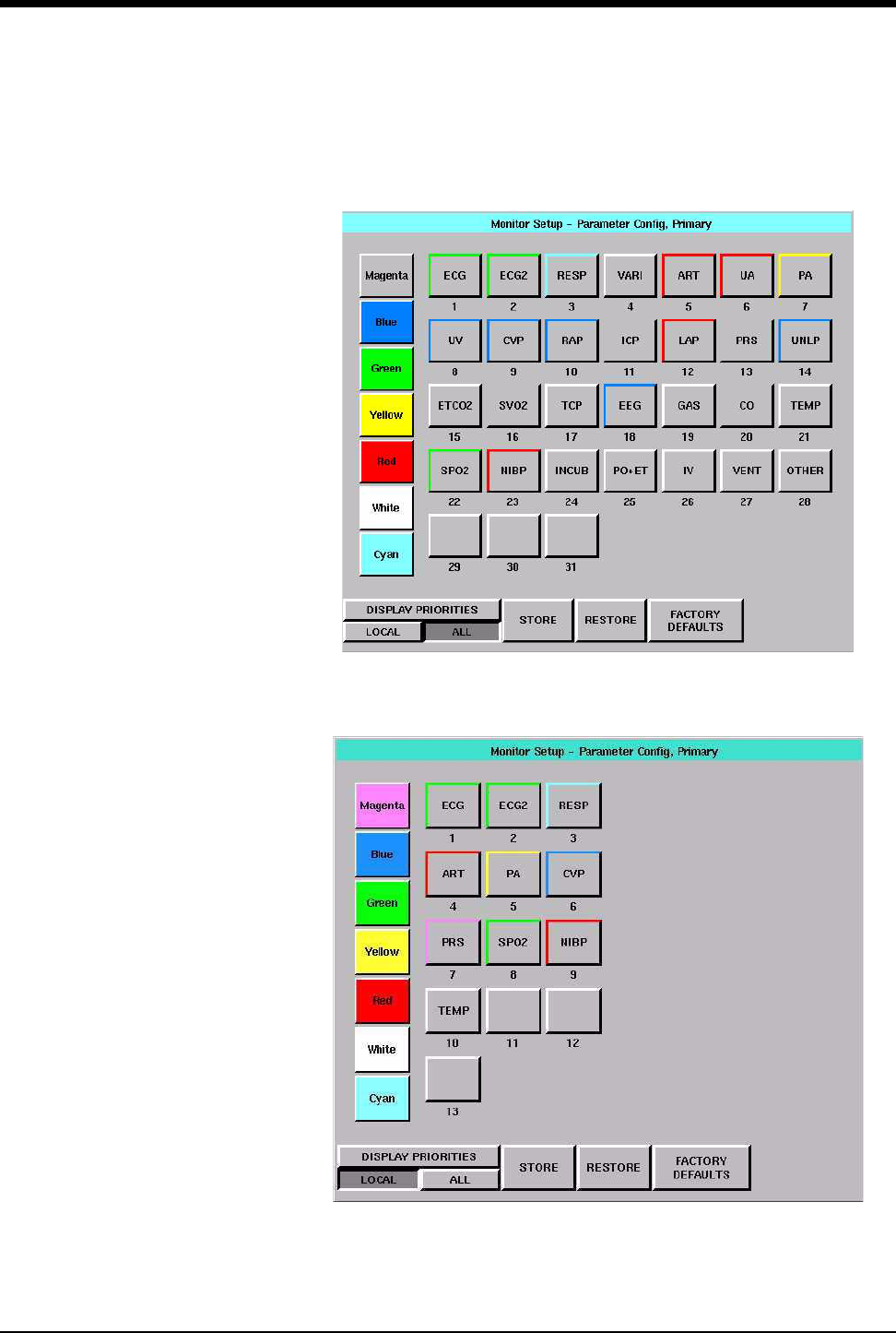
Ultraview Care Network
5-8
On the UCW and Ultraview 1700 Parameter Configuration screen, you can touch
ALL to display all color configurations (Figure 5-3) or touch LOCAL to display the
local color configurations (Figure 5-4).
Figure 5-3: UCW and Ultraview 1700 parameter configuration (ALL selected)
Figure 5-4: UCW and Ultraview 1700 parameter configuration (LOCAL selected)

Bedside/Transport Monitors
5-9
Figure 5-5: Ultraview 1050, 1500, 1600 parameter configuration
The Parameter Configuration screen enables you to change the monitor’s default
priorities and colors.
Each parameter is displayed in order, and is based upon its assigned priority. The
highest priority appears at the top of the screen.
Blank parameter keys enable you to insert a space above, between, or below
other parameters. Blanks of any priority can be inserted into a template by
selecting the blank and putting it into the desired location. This causes a blank
zone to be inserted into the corresponding display area and pushes down all
active parameters with a lower priority.
Not available on
Ultraview 1030
monitors
ART CO CVP ECG1 WHITE 1
ECG1
2
ECG2
3
RESP
4
VARI
ECG2 EEG ETCO2 GAS RED 5
ART
6
UA
7
PA
8
UV
ICP INCUB
WARMR IV LAP GREEN 9
CVP
10
RAP
11
ICP
12
LAP
NIBP OTHER PA PO+ET BLUE 13
PRS
14
UNLP
15
ETCO2
16
SPO2
PRS RAP RESP SPO2 YELLOW 17
NIBP
18
SVO2
19
TCP
20
EEG
SVO2 TCP TEMP UA CYAN 21
GAS
22
CO
23
TEMP
24
INCUB
UNLP UV VARI VENT MAGENTA 25
PO+ET
26
IV
27
VENT
28
OTHER
INS
BLANK
DEL
BLANK 29 30 31 32
STORE RESTORE FACTORY
DEFAULTS
!
• Your monitor or workstation may not be configured to allow
changes to parameter priorities or colors. Contact your system
administrator for details.

Ultraview Care Network
5-10
For the UCW and Ultraview 1700, the DISPLAY PRIORITIES key displays a list of
the currently active parameters, or all possible parameters, ordered by priority.
Touch LOCAL to display only this bed’s currently active parameters.
STORE — causes the currently displayed parameter priorities and colors to be
stored in memory.
RESTORE — causes the last stored local priority and color settings to be restored
from memory.
FACTORY DEFAULTS — causes the factory default priority and color settings to
be restored.
Data Shuttle Option
The Data Shuttle option enables you to transfer patient admit data (e.g., age,
gender, name, and BSA) and up to 24-hours of trend and episodic data from one
monitor to another using a 90496 Ultraview Command Module.
You can transfer data acquired through any Ultraview Care Network module or
Flexport interface. Before you shuttle data from one monitor to another, you must
first transfer the data from the source monitor into a 90496 module. When you
remove the module from the source monitor and insert it into the receiving
monitor, data can be transferred to the receiving monitor.
Transferring Data to the Module
If your monitor and module support the Data Shuttle option, the monitor displays a
TRANSFER DATA key in your ECG Setup menu. When you wish to transfer data
(for example when transporting a monitored patient from one unit to another),
touch the TRANSFER DATA key to initiate data transfer into the module. The
monitor will then display the message TRANSFERRING PATIENT DATA INTO
MODULE.
!
• The time and date set on both the sending and receiving
monitors must be identical for the data transfer to be
successful.
!
• The Data Shuttle option is only available in bedside or transport
monitors. Central monitors do not display keys and messages
related to data transfer.
• If you insert a module that supports the Data Shuttle option into
a monitor that does not have the option, the monitor will not
display data transfer messages and keys.
To transfer data:
1Touch ECG.
2Touch SETUP.
3Select TRANSFER DATA.
4Remove module after DATA
TRANSFER COMPLETED is
displayed.

Bedside/Transport Monitors
5-11
Once the data is completely transferred, the monitor sounds a tone and displays
the message DATA TRANSFER COMPLETED below the UPDATE TRANSFER
and CANCEL TRANSFER keys. The module is now ready to be removed from
that monitor.
Figure 5-6: Data Transfer Completed display
If you do not transfer the module to the receiving monitor immediately, the source
monitor will be storing new data, but the module’s transfer data is not
automatically updated.
After 2-minutes, a tone will sound once each minute to remind you to update the
module with the newly acquired data and the monitor will display the message
DATA TRANSFER COMPLETED.
The message DATA IS XX MINUTES OLD displays the amount of time that has
elapsed since you last transferred the data. The monitor updates this message
each minute.
Updating the Data Transfer
If time has elapsed between data transfer into the module and module removal,
you may wish to update the transferred data before you remove the module. To
update this data, touch UPDATE TRANSFER.
While the data is being updated, the monitor re-displays the message
TRANSFERRING PATIENT DATA INTO MODULE.
Canceling the Data Transfer Before Module Removal
Touch the CANCEL TRANSFER key to clear all data transfer messages and keys
from the ECG display zone and purge previously transferred data from the
module. The monitor will then reactivate the TRANSFER DATA key in the ECG
Setup menu.
!
• Parameter information acquired between the time you transfer
data and the time you remove the module is lost. The monitor
indicates this lost information as a gap in the trends of the
parameters involved when you retrieve the data.
• To provide seamless trend information, remove the module and
insert it into the receiving monitor within 30- to 45-seconds after
you transfer the data. If there is a delay in completing the data
shuttle, update the transfer data just before you remove the
module.
• If the module has been out of the monitor for 10 or more
minutes, all data will be lost.
E
C
G
CANCEL TRANSFER
UPDATE TRANSFER
DATA TRANSFER COMPLETED
To update transfer data, touch
UPDATE TRANSFER.
To cancel data transfer, touch
CANCEL TRANSFER.
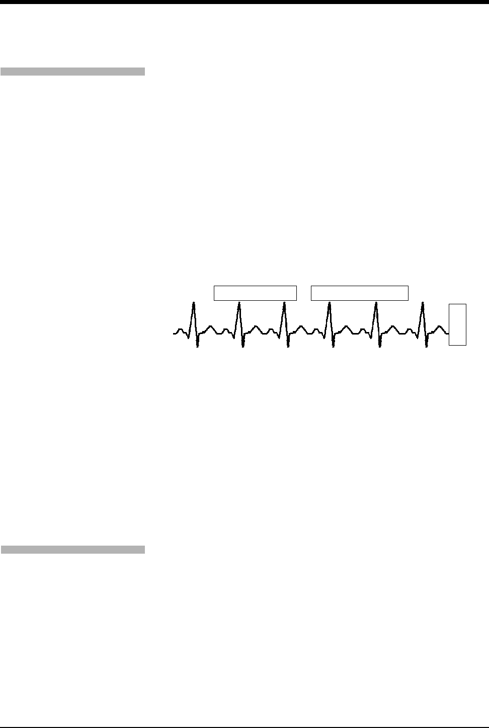
Ultraview Care Network
5-12
Retrieving Transfer Data
When you insert the module into the receiving monitor, the monitor displays the
RETRIEVE DATA and CANCEL TRANSFER keys and sounds a low priority alarm
tone every 5-seconds until you either cancel the data transfer or retrieve the data.
The monitor also displays the patient name associated with the data to be
transferred and, if applicable, the patient name associated with the data that
currently resides in the monitor.
When you touch the RETRIEVE DATA key, the monitor displays YES and NO
keys along with the following message:
YES purges the monitor’s data and retrieves data from the module.
NO cancels this action.
Touch NO to return to the previous screen. Touch YES to transfer the data from
the module into the receiving monitor and purge any data previously stored in that
monitor.
Figure 5-7: Retrieving Transfer Data display
Once you initiate data retrieval, the monitor removes all data transfer-related keys
from the ECG display zone and displays the message TRANSFERRING
PATIENT DATA INTO MONITOR. When the data retrieval into the monitor is
complete, the monitor displays the message DATA TRANSFER COMPLETED.
for one minute.
When you insert a module loaded with transfer data, you cannot purge a prior
patient's data (while data is being transferred) using the monitor’s Admit or
Discharge menus. If you attempt to purge patient data in this manner, the monitor
will display the following message:
Purge is not allowed during transport.
Canceling the Data Transfer After Module Insertion
To cancel a data transfer, touch the CANCEL TRANSFER key. The monitor
displays YES and NO keys along with the following message:
YES purges data previously transferred into the module.
NO cancels this action.
Touch YES to confirm the cancellation of the data transfer and reactivate the
TRANSFER DATA key in the ECG Setup menu. Touch NO to return to the
previous screen.
To receive transferred data:
1Touch RETRIEVE DATA.
2Touch YES.
CST
E
C
G
CANCEL TRANSFER
Module: Jones, B
Monitor: Adams, S
RETRIEVE DATA
To cancel data transfer:
1Insert module into receiving
monitor.
2Touch CANCEL TRANSFER.
3Touch YES.

Bedside/Transport Monitors
5-13
Ultraview 1030/1050 Batteries
Each transport monitor is shipped with one 12 V battery. Monitors will accept two.
Batteries may be changed during battery or AC operation without losing data,
provided that one charged battery remains connected at all times during the
exchange.
A green LED in the lower-right corner of the front panel will flash when the
batteries are charging and will be continually illuminated once the batteries are
fully charged.
Sealed Lead Acid (SLA)
Sealed Lead Acid batteries only need to be charged for about 4-hours prior to use.
When storing, be sure to maintain their charge or to “top charge” them every three
months. These batteries are compatible with all 1030/1050 monitors.
Nickel Metal Hydride (NiMH)
Prior to use, Nickel Metal Hydride batteries should be run through three
charge/discharge cycles in the monitor. This will ensure that during the first
transport maximum run time will be possible. No other maintenance is required for
this battery type.
NiMH batteries may only be used in the Ultraview 1030/1050, with serial numbers
starting at 369-1xxxxx or 367-1xxxxx.
Figure 5-8: Ultraview 1030/1050 monitor battery installation
Ultraview 1030/1050
battery
battery
compartment
door
power on/off switch
LED

Ultraview Care Network
5-14
Battery Status Messages
The Ultraview 1030/1050 provides you with several battery condition status
messages.
Battery Charged — A Solid Green LED
A solid green LED indicates the battery, or batteries, installed into the monitor are
fully charged and are ready to be used.
It functions with the monitor powered ON and with the monitor powered OFF.
Battery Charging — A Flashing Green LED
A flashing green LED indicates the battery, or batteries, installed in the monitor
are not fully charged and are not ready to be used. The flashing is different than
the battery fault detection flash.
The flashing LED turns on and off in a constant pattern, with no delays. It
functions with the monitor powered ON and with the monitor powered OFF.
Battery Fault Detected — An Intermittent Flashing Green LED
An intermittent flashing green LED indicates that either battery A or battery B is
faulty. Faulty batteries are determined to be batteries which do not hold a charge
or batteries which attempt to charge too long. The flashing is different than the
battery charging flash.
The intermittent signal will display a solid green LED for one second and then
display a flashing LED for one second in a repeating pattern. An error log
message is also added to the CMOS error log for review by your system
administrator.
To determine whether one battery, or both, is faulty, power the monitor ON using
the front panel switch and observe the display message. The message will display
along the bottom of the monitor indicating whether one, or both, of the batteries
are faulty. Replace the faulty battery with a fully charged battery.
Battery Gauge
The battery gauge is always present in the lower-right corner of the display when
the monitor is powered ON and not plugged into AC power. This gauge indicates
the approximate battery capacity. For example, the gauge will display:
• a fully charged battery
• 3/4 battery charge remaining
• 1/2 battery charge remaining
• 1/4 battery charge remaining
• minimum battery charge remaining
!
• If a battery is not installed, a solid green LED will also display.

Bedside/Transport Monitors
5-15
Recordings are automatically inhibited when the battery power reaches
1/2 battery charge remaining.
The entire battery gauge flashes to emphasize this danger warning.
Wireless Network Interface
The Wireless Network Interface (WNI) provides Ultraview 1030/1050 monitors
equipped with the wireless option to communicate with the Spacelabs Medical
Ethernet network. This enables the wireless bedside monitor to communicate with
a central station and other networked devices.
The WNI provides wireless transmission of up to five waveforms along with
associated numerics, alarms, trends, arrhythmia, ST, and Flexport Interface
systems data.
Alarm Watch and Remote Trends are not restricted. Bed-to-bed communications
enable a bedside to use the Remote View or Alarm Watch features to view data
from other beds on the wireless or hardwired network.
Outbound Parameters Menu
To view the Outbound Parameters menu, touch the OUTBOUND PARAMETERS
key in the Monitor Setup menu.
When a parameter key is ON, the parameter is available for selection in another
monitor’s Remote View menu and Select Outbound Parameters menu. If two
parameters have identical labels, both parameters will display. The maximum
number of parameters that can be set depends upon the monitor’s specific
configuration for wireless networking. When the maximum number of parameters
is reached, the remaining parameters that were not selected become unavailable.
The monitor’s default outbound parameter selection is ECG1 when turned ON.
All parameters, including the parameters that are set to OFF in this menu, are
displayed by other monitors that are set to ALARM WATCH this monitor. If an
outbound parameter is set to OFF, all existing remote views for that parameter will
be dropped.
!
• When the battery power reaches 1/2 battery charge remaining,
recordings that drain large amounts of power can cause the
monitor to power OFF without warning.
!
• When the battery power becomes critically low (approximately
1/4 battery charge remaining), the monitor may power OFF at
any time, depending on monitor loading.
!
• Setting OTHER to ON selects any unlisted channel types such
as VARI, CO, and unlabeled pressures.
To select parameters to be
monitored:
1Touch MONITOR SETUP.
2Touch OUTBOUND
PARAMETERS.
3Select the parameters you wish
to display (up to five).
To change parameters:
1Touch MONITOR SETUP.
2Touch OUTBOUND
PARAMETERS.
3Deselect the parameter key
that you wish to stop
displaying.
4Select the parameter you wish
to display.
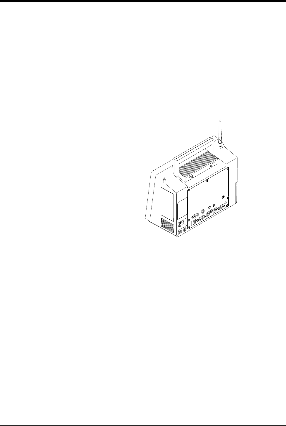
Ultraview Care Network
5-16
Wireless Ethernet Connection
Ultraview 1030/1050 Monitors (Option Z)
In wireless mode, the monitor maintains network communication with a central
station through the Wireless Network Interface (WNI) that is connected to the
standard Spacelabs Medical hardwired Ethernet network. Wireless
communication is automatically disabled when the monitor is directly hardwired to
the network using its network port, and enabled when the hardwired port is
disconnected.
Figure 5-9: Rear panel Ultraview 1030/1050
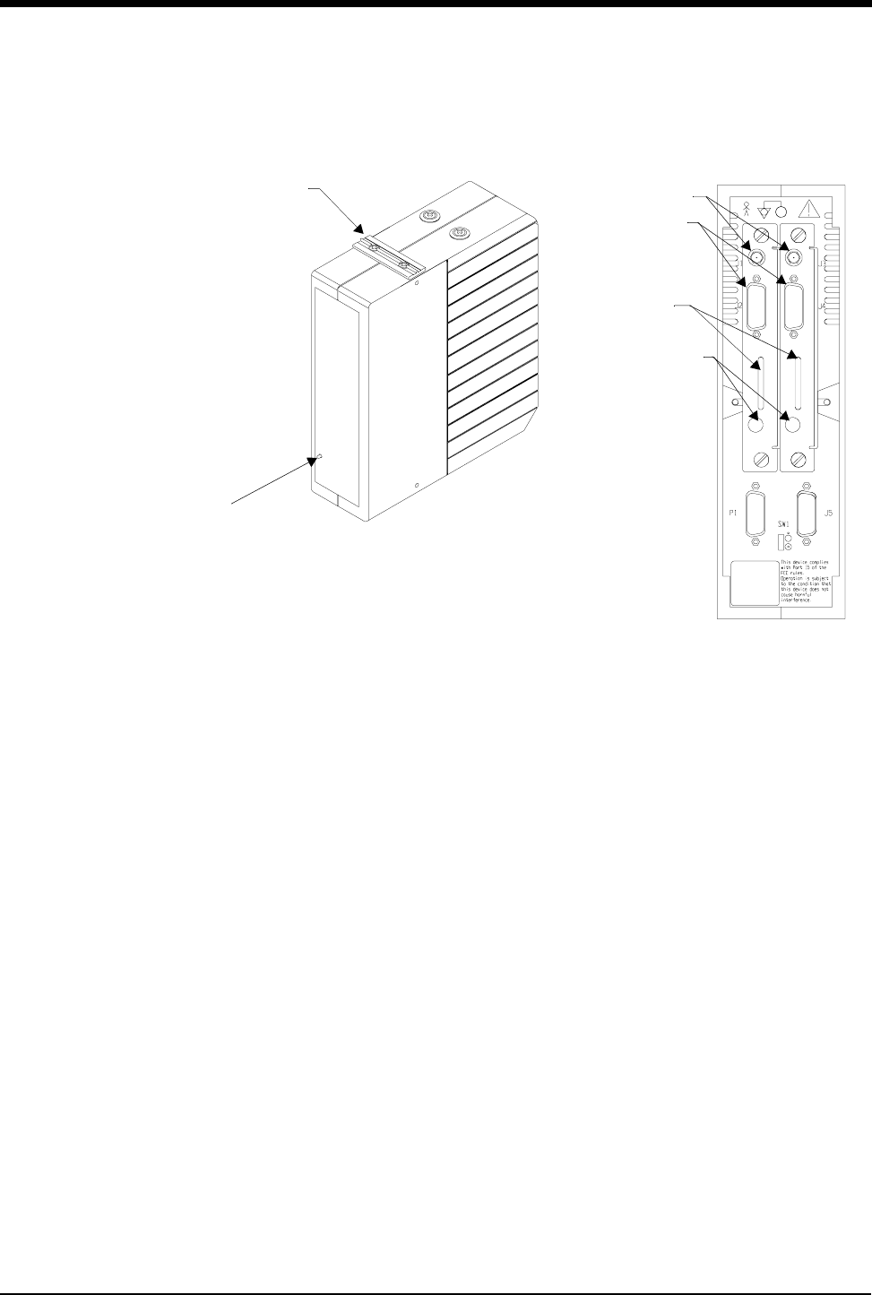
Bedside/Transport Monitors
5-17
Optional Model 90310 Wireless Network Interface
Figure 5-10: 90310 Wireless Network Interface
rack mounting
power LED
hardware
(single or double)
90310 front panel
antenna
ã
status LEDs
channel selection
thumbwheel
connectors
connects to AUI
multiport for
wireless network
90310 rear panel
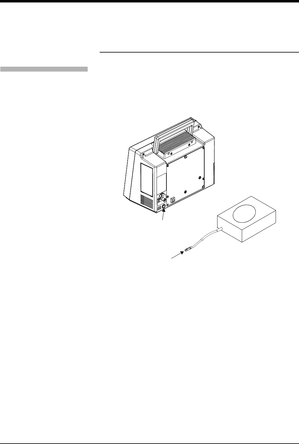
Ultraview Care Network
5-18
Ultraview 1030/1050 Connections
External Power Supply Connection
The connection for the external power supply is shown in Figure 5-11. The green
LED on the front panel will display ON whenever the unit is powered by an
external power supply.
Figure 5-11: Ultraview 1030/1050 external power supply connection
To connect to an external power
supply:
1Attach the DC outlet cable to
J1.
2Connect the power cord of the
external power supply to an AC
outlet.
J1 - external
power supply
connection
external power
supply
DC outlet
cable
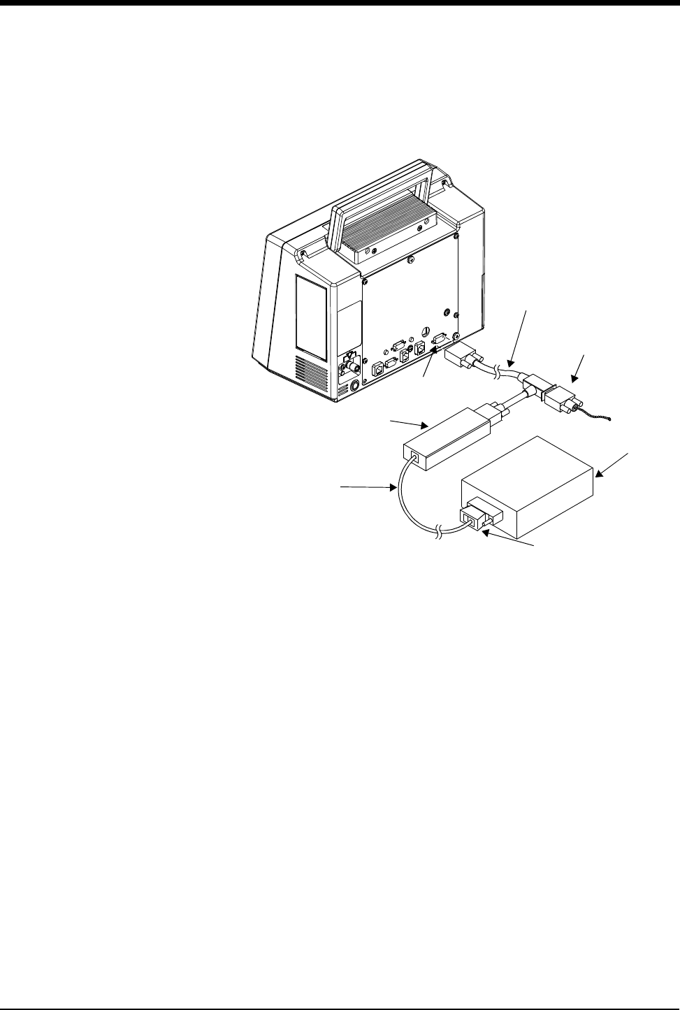
Bedside/Transport Monitors
5-19
The Ultraview 1030/1050 also provides an external Flexport System Interface
connection (Figure 5-12).
Figure 5-12: Ultraview 1030/1050 external Flexport connection -
interface connector option F or G
SDLC cable
SDLC
terminator
SDLC
connection
Flexport
interface
modular cable
external
device
transition
connector
P/N 012-0182-00
P/N 012-0152-00
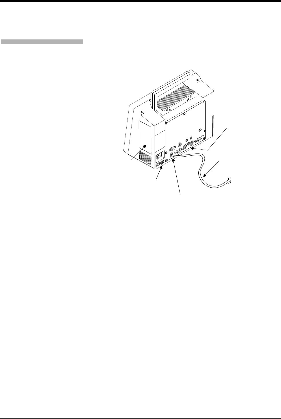
Ultraview Care Network
5-20
Ethernet Connection - Options F or G for Ultraview
1030/1050
Figure 5-13: Ultraview 1030/1050 10BaseT network connection
To connect to the 10BaseT port
for network communication:
1Plug either end of cable
assembly 175-0951-XX into the
modular jack connection on the
back of the monitor.
Network communication is done
through the 10BaseT cable
assembly only.
2Plug the other end of the cable
into the wall in a wall plate with
an eight pin modular jack
connector.
10BaseT
cable assembly
modular
jack connection
P/N 175-0951-XX
patient
module
slot
J1 - external
power supply
connection
remote alarm
connection
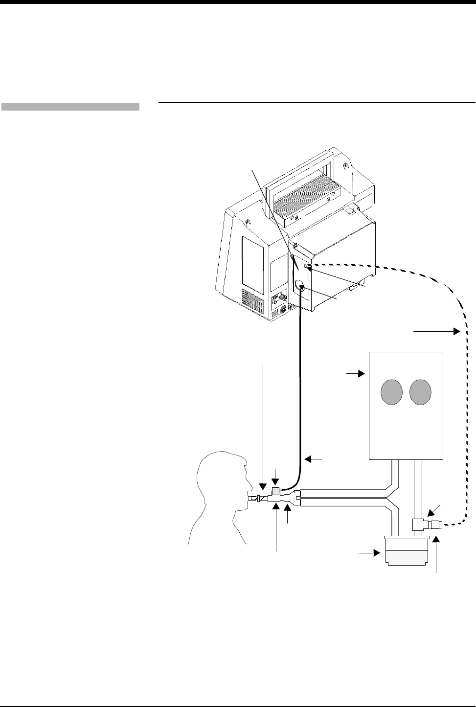
Bedside/Transport Monitors
5-21
Ultraview 1030/1050 with Capnography
(Option G or H)
Option G adds mainstream EtCO2 monitoring to the Ultraview 1030/1050.
Figure 5-14: Ultraview 1030/1050
rear panel with option G or H
To start capnography
monitoring:
1Plug the mainstream EtCO2
sensor cable into the EtCO2
receptacle on the capnography
panel.
2Perform sensor calibration, if
necessary.
3Prepare the patient according
to hospital procedures.
4Select the appropriate airway
adapter (neonate or adult).
5Verify that the windows are
clean and dry.
6Place the sensor head over the
airway adapter and perform an
adapter calibration, if
necessary.
7Remove the airway adapter
from the sensor head.
8Insert the airway adapter into
the ventilator circuit and Ballard
style tracheal suction system (if
present) as shown.
9Attach the sensor head to the
airway adapter.
10 Make the other connections as
shown.
11 Ensure that the sensor head is
always positioned above the
ventilator circuit so that
moisture will not enter the
adapter.
O2
EtCO2
endotracheal
mainstream
airway
ventilator
humidifier
adapter
O2 sensor
capnography
panel
inspiratory circuit
expiratory circuit
O2adapter
cable
O2 airway
adapter
tube
cable
sensor
head sensor
ventilator
circuit

Ultraview Care Network
5-22
Maternal Obstetrical Monitor - 94000
The Maternal Obstetrical Monitor (MOM) is a fetal monitor which, when used with
an Ultraview Command Module or other Ultraview modules, provides the optional
ability to monitor maternal ECG, NIBP, temperature, and SpO2. The multiple trace
screen enables simultaneous display of real-time fetal and maternal ECG and
maternal SpO2. Both internal and external fetal monitoring capabilities are
provided.
The monitor provides networking capabilities to Spacelabs Medical monitors
through an Ethernet network, BirthNet®, and other manufacturers’ fetal data
management systems.
Data for the fetal heart rate and uterine activity can be captured using telemetry or
Mermaid wireless technology options.
WARNING:
• Shock hazards may exist if this instrument is not properly
grounded. Protection against electrical shock is provided
by grounding the chassis with a three-wire cable and plug.
The grounding wire must not be removed or defeated.
Grounding reliability can only be assured if connected to a
receptacle marked Hospital Only or Hospital Grade.
• To reduce the risk of electric shock, do not remove the
protective covers. Only qualified Spacelabs Medical
personnel should service the instrument.
• There is a risk of explosion if the instrument is operated in
the presence of flammable anesthetics.
• Always inspect the transducer face, housing, cable, and
power cord before using the instrument. If the transducer
is cracked or chipped, or if the power cord is frayed,
broken, or otherwise damaged, call a qualified technician.
Do not use the transducer or the monitor on a patient.
• Always disconnect the instrument from the power supply
prior to cleaning the monitor.
• The total system chassis risk current should not exceed
300 µA @ 120V, 500 µA @ 240V.
• Do not operate this instrument if it is wet or if condensation
is present.
• During recharging, the wireless transducers may become
hot or warm to the touch. Allow the wireless transducers to
cool prior to using them on a patient.
• An intentional reset will occur if the processors lose
communication with each other. Under these
circumstances, the main processor will self-reset and the
communication will be re-established after the startup
sequence. A solid triangle is printed on the 60-bpm line of
the FHR scale to differentiate this type of reset from others.
A small gap in the heart rate tracing will result.

Bedside/Transport Monitors
5-23
CAUTION:
• Excessive bending or twisting of a transducer cable may
cause failure or intermittent operation of the transducer.
• Do not sterilize a transducer using gas, heat, or liquid
methods. Do not autoclave a transducer. These
sterilization methods may permanently damage the
transducer.
• This instrument is not intended for use with
defibrillators.
• Disposal of these devices and all accessories must be in
accordance with local and federal laws.
• Due to the potential for electromagnetic interference,
electronic devices (for example, portable communication
transmitters, cellular telephones, personal computers,
electronic toys, and other medical devices) should not
be operated within 3.5 feet (1.07 meters) of the patient,
patient leads, or associated patient monitoring
equipment until evaluated by the Biomedical
Engineering staff.
• If the integrity of the external protective earth conductor
is in doubt, the equipment must be operated from its
internal power source.
• The fetal module is an IEC 601-1 Class I device with type
B, BF, and CF patient connectors. Type B equipment
provides a particular degree of protection against
electric shock, particularly regarding allowable leakage
current (not to exceed 0.1 mA) and reliability of the
protective earth connection (if present). Type BF
equipment meets the criteria above for B with an F-type
applied part. An F-type applied part is isolated from all
other parts of the equipment to such a degree that the
patient leakage current allowable in single fault
condition is not exceeded with a voltage equal to 1.1
times the highest rated mains voltage applied between
the applied part and earth. Type CF equipment provides
a degree of protection higher than that for type BF
against electroshock, particularly regarding allowable
leakage currents (not to exceed 0.01 mA), and having an
F-type applied part.
• Water ingress for the fetal module is IPX0; water ingress
for the Mermaid transducers is IPX7 per IEC 529.
• The MOM unit is not approved for transport applications.
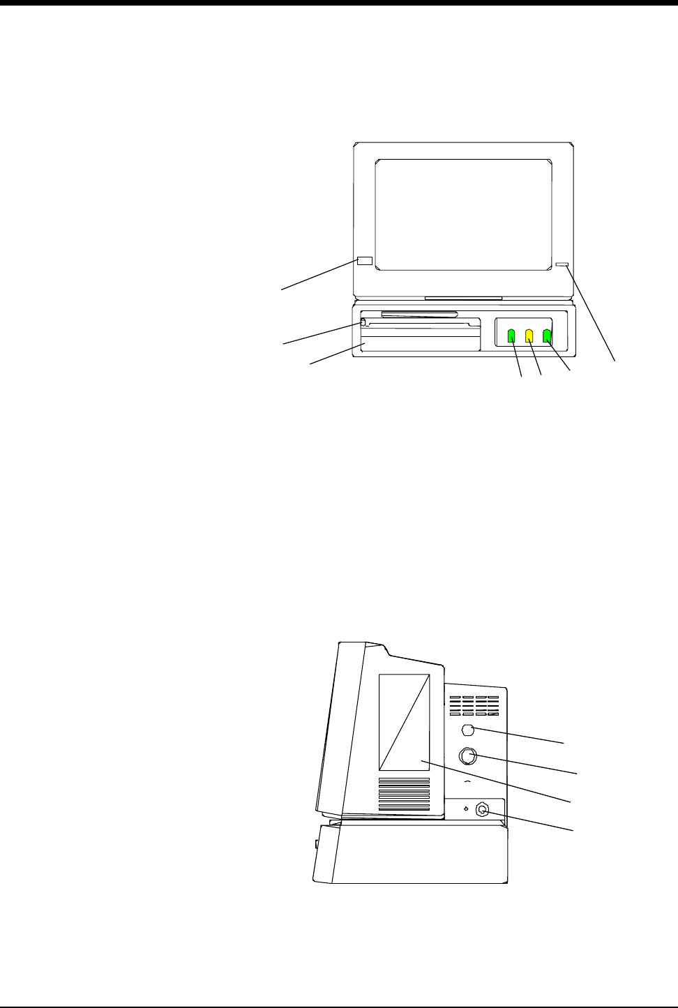
Ultraview Care Network
5-24
Front Panel
Power ON/OFF
Recorder drawer release button
Fetal chart recorder
FHR 1 connector (either ultrasound or ECG)
UA connector
FHR 2 connector (ultrasound only)
Battery charging light
Right Side Panel
Telemetry antenna connector (optional)
Mermaid wireless connector (optional)
Ultraview Module (optional)
J1 - External power supply connector
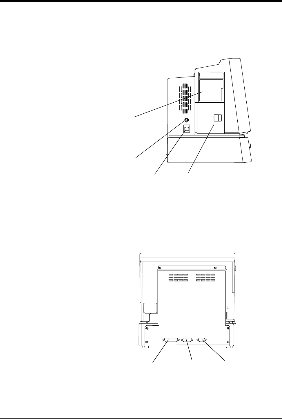
Bedside/Transport Monitors
5-25
Left Side Panel
Maternal chart recorder (optional)
Event marker connector
Ethernet connector (Ultraview Care Network)
Battery compartment door
Rear Panel
J4 - Other I/O
J3 - RS485 port - BirthNet
J2 - External device port - RS232

Ultraview Care Network
5-26
WARNING:
• The use of accessory equipment that does not comply with
the monitor’s safety requirements may lead to a reduced
level of safety. Consideration should be given to the use of
the accessory in the vicinity of a patient. The safety
certification of the accessory must be performed in
accordance with the appropriate IEC 601-1 and/or
IEC 601-1-1 harmonized national standard.
• EMC compliance may be compromised by the connection
of accessory and/or peripheral equipment. Compliance of
accessory and/or peripheral equipment must be considered
to ensure continued EMC compliance.

5-27
Bedside/Transport Monitor Troubleshooting Guide
Clinical Situation Possible Cause Solution
Cannot change parameter
priority or colors
■Monitor may not be set up to allow
the user to change priority or colors.
■Contact your system administrator.
Changed parameter priority
or colors are lost
■The STORE key was not touched
after the selection was made.
■Touch the STORE key to make
changes permanent.
Transport monitor has no DC
power
■The monitor was not plugged into an
AC outlet while not in use.
■Plug the monitor into an AC outlet
to recharge batteries to 80% power
(refer to Battery Gauge on page 5-
14).

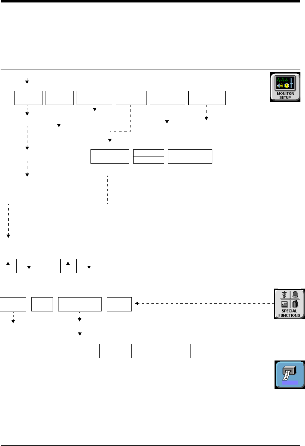
6-1
!
• Based on features purchased, more or fewer keys may appear here than on your menu screens.
Central Monitors Directory
Directory of Keys - UCW and Ultraview 1700
SCREEN
FORMAT
TONES
ADMIT/
DISCHARGE
MONITOR
CONFIG.
BRIGHTNESS
Select waveform
zone
Select bed
(or subnet, then bed)
Select parameter
Refer to
Refer to
CLOCK
ON OFF
PRIVILEGED
ACCESS
Refer to Selecting Waveforms for Display
in this chapter
MONITOR SETUP
MONITOR CONFIGURATION
ACTIVATE
SCREEN SAVER
the next page
RECORD
Refer to
chapter
Alarms
ALARM
WATCH
GRAPHIC
TRENDS
TABULAR
TRENDS CALCS DRUG
CALCS
AW
OFF
REMOTE
TRENDS/CALCS
TRENDS/CALCS for BED XXX
Select bed
SPECIAL FUNCTIONS
RECORDER
CONFIG.
CONTRAST
Refer to
Admit/Discharge
MONITOR SETUP -
BRIGHTNESS CONTRAST
Ultraview UCW
DNA
DISPLAY BRIGHTNESS AND CONTRAST
and 1500 only
chapter Refer to
Printing chapter
Refer to
Printing chapter
Alarms chapter
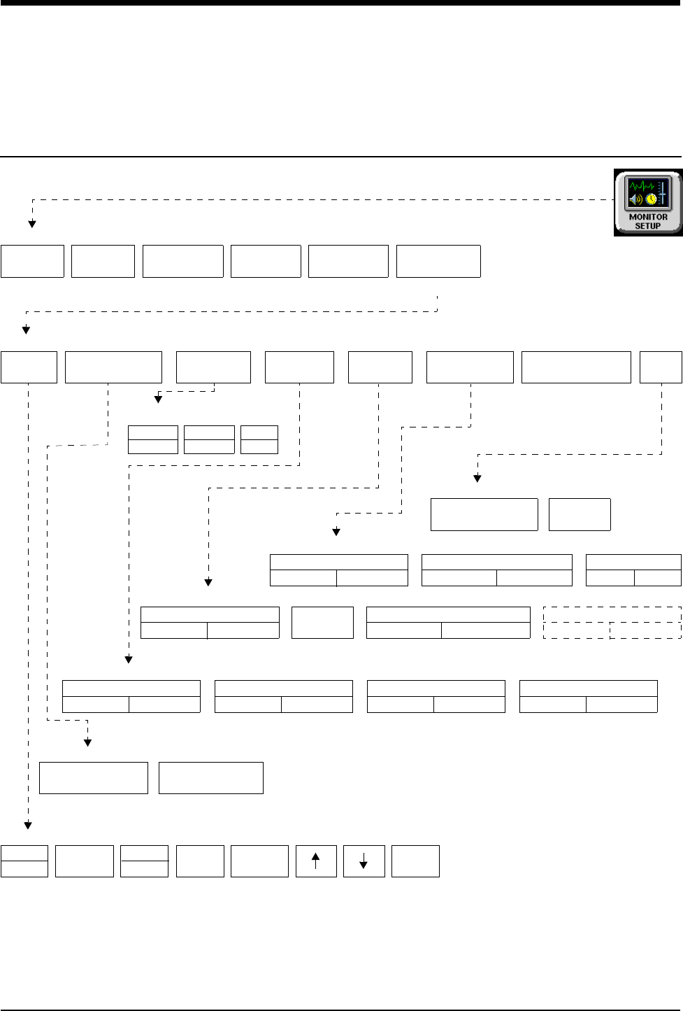
Central Monitors Directory
!
• Based on features purchased, more or fewer keys may appear here than on your menu screens.
6-2
Directory of Keys - Privileged Access
Enter clinical password
SCREEN
FORMAT
TONES
ADMIT/
DISCHARGE
MONITOR
CONFIG
PRIVILEGED
ACCESS
MONITOR SETUP
RECORDER
CONFIG
ROTATE ALARM WATCH
ALARM WATCH SETUP - Select parameter to change
PRESELECTED RECORDINGS - Select configuration to change
RESET
MONITOR
CHANGE CLINICAL
PASSWORD
CLINICAL LEVEL - Select Parameter
UNITS OF
MEASURE
USER
ACCESS
ALARM
SETUP
CLINICAL LEVEL - Select Parameter
TIME/
DATE
TIME
DATE
24 HOURS ENTER
USER ACCESS - Enable user access to functions
PRESELECTED A PRESELECTED B
ALARM WATCH ROTATION
PRIORITY
MINUTES
mmHg
kPa
inches
cm
lb
kg
MONITOR SETUP - Time/Date 10:06 AM/PM
ROTATION TIME
15 S 30 SSIMPLEON OFF
AM
PM
ALARM WATCH
SETUP
Restart monitor after selecting
units of measurement
ALARM SETUP - Select parameter
PRESELECTED
RECORDINGS MORE
REMOTE ACCESS
ON OFF
ALARM
RELAY
QRS/SPO2 TONE ENABLE
ALWAYS DURING ALARM
ALARM WATCH TONE
SINGLE TRIPLE
PATIENT TYPE
ON OFF
PARAMETER CONFIG
ON OFF
RECORDING DURATION
ON OFF
SUBNET ACCESS
ON OFF
HOURS
REMOTE KEYPAD
STATION ADDRESS

Contents
6-3
Overview . . . . . . . . . . . . . . . . . . . . . . . . . . . . . . . . . . . . . . . . . . . . . . . . . . . . . . 3
Display Detail. . . . . . . . . . . . . . . . . . . . . . . . . . . . . . . . . . . . . . . . . . . . . . . . . . . 4
6-Trace Option. . . . . . . . . . . . . . . . . . . . . . . . . . . . . . . . . . . . . . . . . . . . . . . . . . 4
Central Monitor Features . . . . . . . . . . . . . . . . . . . . . . . . . . . . . . . . . . . . . . . . . . 5
System Clock. . . . . . . . . . . . . . . . . . . . . . . . . . . . . . . . . . . . . . . . . . . . . . . . . . . 6
Screen Saver . . . . . . . . . . . . . . . . . . . . . . . . . . . . . . . . . . . . . . . . . . . . . . . . . . . 7
Data Communications Watch . . . . . . . . . . . . . . . . . . . . . . . . . . . . . . . . . . . . . . 7
Central Monitors Troubleshooting Guide . . . . . . . . . . . . . . . . . . . . . . . . . . . . . . 9
Central Monitors
Overview
The central monitor provides full monitoring control of remote parameters
including display and alarms, with both visual and audible annunciation. All
waveform and current numeric data, arrhythmia, ST segment, and trends are
available with central monitoring.
The Ultraview Care Network family of monitors and modules have built-in error
detection and recovery circuitry. This circuitry, together with special software,
allows the central to re-initialize and continue to function if an error occurs.
When the system detects an error that cannot be corrected through other means,
the central monitor re-initializes or resets (blanks). Normally, a reset involves very
little loss of patient monitoring time (approximately 5-seconds) and, with few
exceptions, all operator set inputs (for example, alarm limits, pressure labels,
transducer offsets, etc.) are retained. The entire process of restoring the central
display following a reset, takes approximately 20-seconds, depending upon the
number of parameters being monitored.
In some cases, stored trend data will be lost when the monitor resets. Typically,
this is indicative of a hardware condition that requires corrective action. In this
case, the system initiates the start-up diagnostics to check the monitor’s operation
so that full recovery takes approximately 10-seconds longer.
If a bedside monitor has reset, the central and bedside monitors display CHECK
SETUP in the ECG zone to alert you to check all limits and values and ensure that
the monitors have restored all preset values. Refer to Power Failure on page 1-4
for more information. This also occurs when the monitors are turned ON or when
an ECG module has been inserted. However, your system administrator may
disable this CHECK SETUP feature.
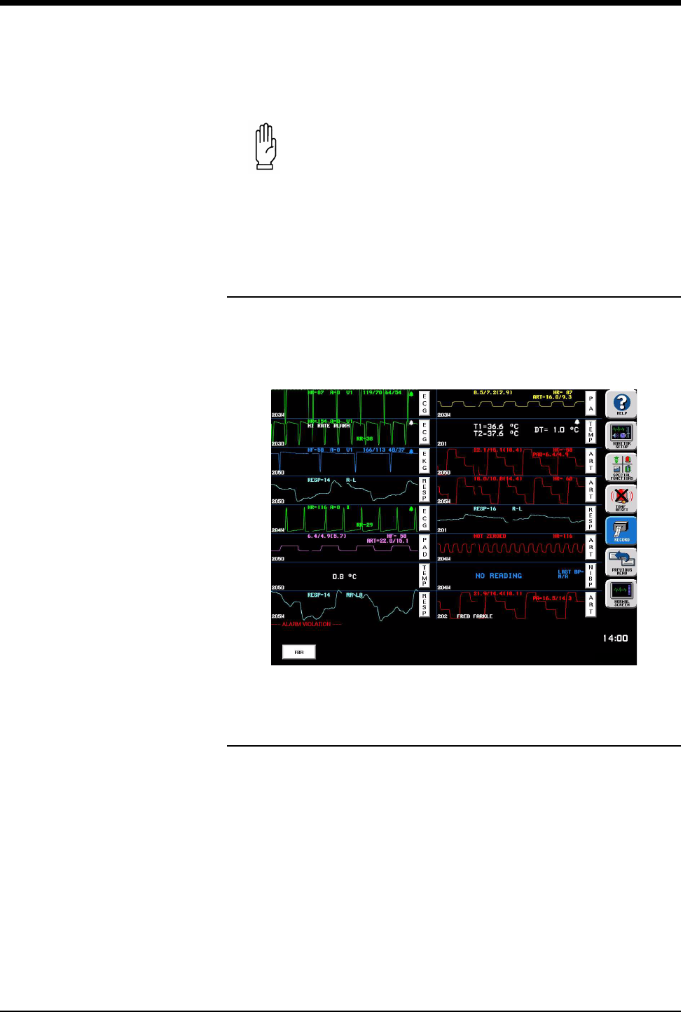
Ultraview Care Network
6-4
Display Detail
UCW and Ultraview 1700 central monitor screens can display up to 8 full
waveform zones. The split screen option allows for a maximum of 12 or 16 zones
to be displayed.
Figure 6-1: Split screen display
6-Trace Option
The 6-trace mode feature includes automatic screen formatting that increases the
font and zone size for alphanumeric text.
The larger font and zone size always appears on central monitors configured for
4-, 5-, 6-, and 12-trace operation because no more than 6 full zones can have
parameters assigned.
CAUTION:
• Due to the potential for electromagnetic interference,
electronic devices (for example, portable communication
transmitters, cellular telephones, personal computers,
electronic toys, and other medical devices) should not be
operated within 3.5 feet (1.07 meters) of the patient, patient
leads, or associated monitoring equipment until evaluated
by the Biomedical Engineering staff.
24 Jun 03
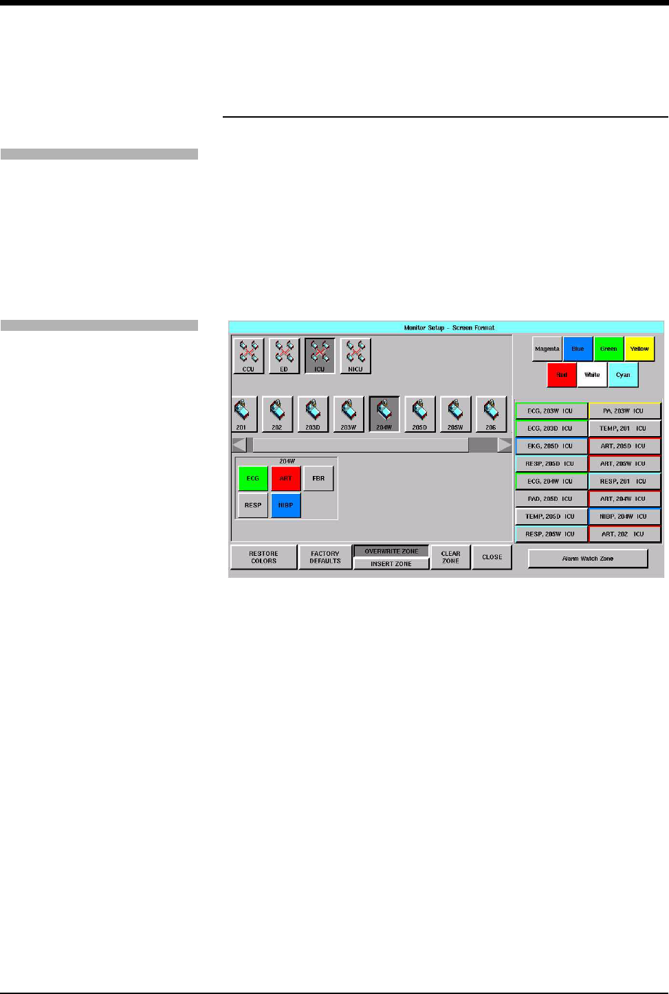
Central Monitors
6-5
Central Monitor Features
Selecting Parameters for Display
Use the SCREEN FORMAT key in the Monitor Setup menu to assign remote
parameters to specific display zones and to choose the color of those zones.
Names of the subnet and bedside keys are assigned by your system
administrator.
One to 8 waveform zones may be displayed across the entire screen. Split screen
central monitors may display 16 waveform zones, with 1 at the top, left zone on
the display, and zone 9 appearing in the 1st zone upper right.
Figure 6-2: Central display - Screen Format menu
RESTORE COLORS — restores the last stored color settings from memory.
FACTORY DEFAULTS — restores the zone colors to the factory color setting of
white.
OVERWRITE ZONE — replaces a zone that has already been assigned a
parameter. Select the new parameter and then touch OVERWRITE ZONE to drop
the previously assigned parameter channel and replace it with the new parameter.
INSERT ZONE — moves the assigned zone and all other zones immediately
adjacent to the assigned zone down one zone, and the new zone is inserted
above them. If this causes an assigned zone to disappear from the screen, a
warning box will appear prompting you to complete or cancel the insert.
CLEAR ZONE — clears the zone assignment and returns the zone to an
unassigned state. Touch CLEAR ZONE, then touch the zone from which you wish
to remove an assignment.
To select remote parameters for
display:
1Touch MONITOR SETUP.
2Touch SCREEN FORMAT.
3Select a bed (or a subnet, then
a bed).
4Select the parameter(s) to be
displayed.
5Select a zone.
To assign color to a zone:
1Touch MONITOR SETUP.
2Touch SCREEN FORMAT.
3Touch the desired color.
4Touch the zone to be colored.
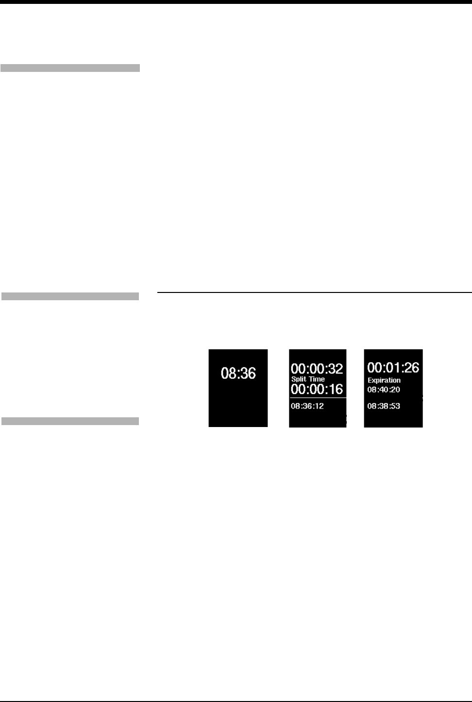
Ultraview Care Network
6-6
Setting the Time and Date
The TIME/DATE key controls both the time and date menus. The current time or
date is displayed above the menu.
Time is displayed in either 12- or 24-hour format. Network monitors display the
network time and stand-alone monitors display the internal system time.
The system will not make any time/date change permanent until you touch
ENTER.
System Clock
A system clock can be continually displayed in the lower right corner of the
screen. The clock feature can also be used as a stopwatch or timer.
Figure 6-3: Clock display formats
!
• Setting the time on any networked monitor sets time for all
monitors on that network.
!
• The digital clock is available for all monitors.
• The stopwatch and timer are only available for the UCW and
Ultraview 1700.
To change the network or internal
system time and date:
1Touch MONITOR SETUP.
2Touch PRIVILEGED ACCESS.
3Enter Clinical password.
4Touch TIME/DATE.
5a Select TIME.
-OR-
5b Select DATE.
6a Select 24-HOURS or AM/PM
(12-hour).
-OR-
6b Select MONTH, DAY, and
YEAR.
7Use arrow keys to set time or
date.
8Touch ENTER.
To enable/disable the clock:
1Touch MONITOR SETUP.
2Touch MONITOR
CONFIGURATION.
3a Select CLOCK ON to enable
the clock.
-OR-
3b Select CLOCK OFF to disable
the clock.
To access the clock menu:
1Touch MONITOR SETUP.
2Touch MONITOR
CONFIGURATION.
3Select CLOCK ON.
4Touch the clock that appears in
the lower right of the screen.
5Select DIGITAL,
STOPWATCH, or TIMER.
digital stopwatch timer
02 JUN 03
02 JUN 03
02 JUN 03
Elapsed Remaining

Central Monitors
6-7
Screen Saver
Activating the screen saver blanks the screen (displaying only the Spacelabs
Medical logo). You may also disable the screen saver by touching the screen,
clicking (or dragging) the mouse, or pressing any key on the keyboard.
Data Communications Watch
The Data Communications Watch (DCW) feature displays a Data
Communications Interrupted (DCI) message on the central when the central’s
communication link to a bedside/remote monitor is interrupted.
A bedside monitor may drop from the central display because of a power
interruption at the bedside, Ethernet failure, or other circumstance. As soon as a
communication loss is detected by the central monitor, a DCI notification will be
displayed on the screen in place of each channel that lost communication, and an
alarm tone will sound if enabled (refer to Enabling Alarms (Optional) on page 6-8).
Keys will be displayed in the waveform zone of the interrupted channel to permit
disabling of the alarm tone associated with the interruption, and to remove the
zone from the display.
The DCI notification shows the bed name, patient name and the parameter key
label of the lost channel, as shown in Figure 6-4.
Figure 6-4: DCI notification display
The parameter key (ECG in the above example) will also flash (if DCW alarms are
enabled) when the DCI notification is displayed on the screen. Touch this key to
display a status message at the bottom of the screen noting the time and date that
communication with the lost channel was interrupted.
Press YES to remove all DCI notifications associated with the same bedside from
the central display. Unless the zone is re-assigned by the user, the central will
continue to attempt communication with the remote monitor. Once communication
is restored, the patient data is displayed in the zones again.
!
• The screen will automatically be restored by an incoming alarm
condition.
!
• The Data Communications Watch feature is enabled only
through the system administrator menu.
To activate the screen saver:
1Touch MONITOR SETUP.
2Touch MONITOR
CONFIGURATION.
3Touch ACTIVATE SCREEN
SAVER.
To enable Data Communications
Watch (must have system
administrator menu access):
1Touch MONITOR SETUP.
2Touch PRIVILEGED ACCESS.
3Enter Biomed password.
4Touch MORE.
5Touch DATA COMM WATCH.
6Select COMM WATCH ON.
7Select ALARM ON to enable
DCW alarms.
8Select ADMIT REQUIRED ON
to enable DCW for admitted
patients only.
REMOVE PATIENT ZONE?
YES
E
C
G
BED 01 JONES, B NO
DATA COMMUNICATIONS INTERRUPTED

Ultraview Care Network
6-8
Press NO to silence the alarms (if enabled), but to continue display of the DCI
notification. All alarms for that bedside monitor are silenced simultaneously. The
NO key becomes dithered (inactive) after it is pressed.
Enabling Alarms (Optional)
When activated, this option causes an alarm to sound and the parameter key to
flash when the DCI notification is displayed. This option must be enabled through
the Biomed menu.
A flashing parameter key and low level alarm tone, signifying an alarm condition,
will occur as soon as the central detects a communication loss. Alarm conditions
will continue until either YES or NO is pressed on the DCI notification, a new
parameter is assigned to the zone, or communication is restored.
Enabling Detection for Admitted Patients (Optional)
If ADMIT REQUIRED is ON, communication will be watched for only those remote
monitors having admitted patients. If ADMIT REQUIRED is OFF, communications
will be watched for all patients on the central monitor.

6-9
Central Monitors Troubleshooting Guide
Clinical Situation Possible Cause Solution
Cannot assign color to a
zone
■Monitor may not be set up to allow
you to assign colors.
■Contact your system administrator.
Cannot assign a
parameter to a zone
■Zone may not have been cleared of
previous assigned waveforms.
■Select CLEAR ZONE, then touch the
zone in which to display the new
parameter. Repeat the initial
SCREEN FORMAT steps.
Cannot access the clock
menu
■Clock may have been left in
STOPWATCH or TIMER mode.
■Touch the clock/timer display, then
touch PREVIOUS MENU to restore
the clock.
CANNOT deselect ALARM
WATCH
■The Ultraview Central Monitor is
configured with Central Alarm Watch
Manager to prevent de-selection of
automatically alarm watched beds.
■Contact your system administrator.

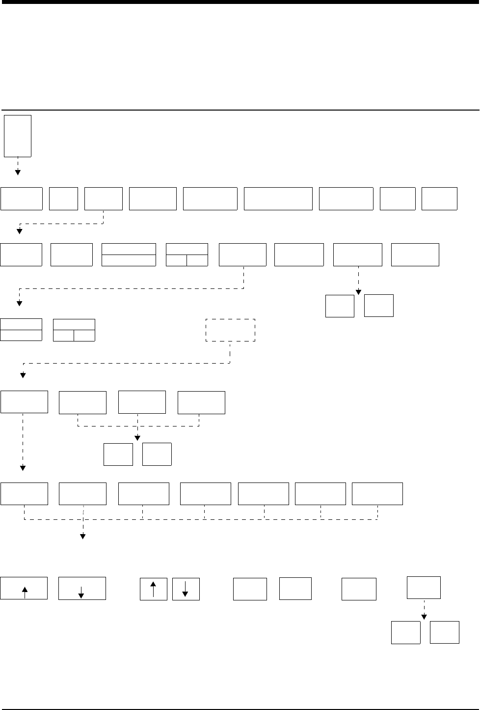
7-1
!
• Based on features purchased, more or fewer keys may appear here than on your menu screens.
Module Configuration Manager
Directory
Directory of Keys - For Configurations With ECG
ECG MENU
ALARM
LIMITS SIZE SETUP LEAD
CONTROL
DISPLAY
FORMAT
SUSPEND
PROCESSING REVIEWPRINTRELEARN
ECG - SETUP
SWEEP
SPEED
RATE
SOURCE
MONITOR
EXTENDED
QRS
TONE
RESTORE
SETTINGS
HIDDEN
KEY
ECG - CONFIG
INFANT
DEFAULT STORAGE MENU
USER
SETTINGS
TRANSFER
SETTINGS
RETRIEVE
SETTINGS
FACTORY
DEFAULTS
STORE
CONFIG
YES NO
See your system
administrator for
access to this key
TRANSFER
DATA
NIBP TEMP
E
C
G
PACED
YES NO
ADULT ARR
ON OFF
USER SETTINGS - CHANNEL SELECT
ECG RESP VARITREND
SELECT PARAMETER
CURSOR CURSOR
User Settings screens appear here
(Refer to Display Detail)
CHANGE VALUE PAGE X OF X
PRES SPO2
YES NO
YES NO
PRINT
PAGE
NEXT
PAGE
PREV
PAGE
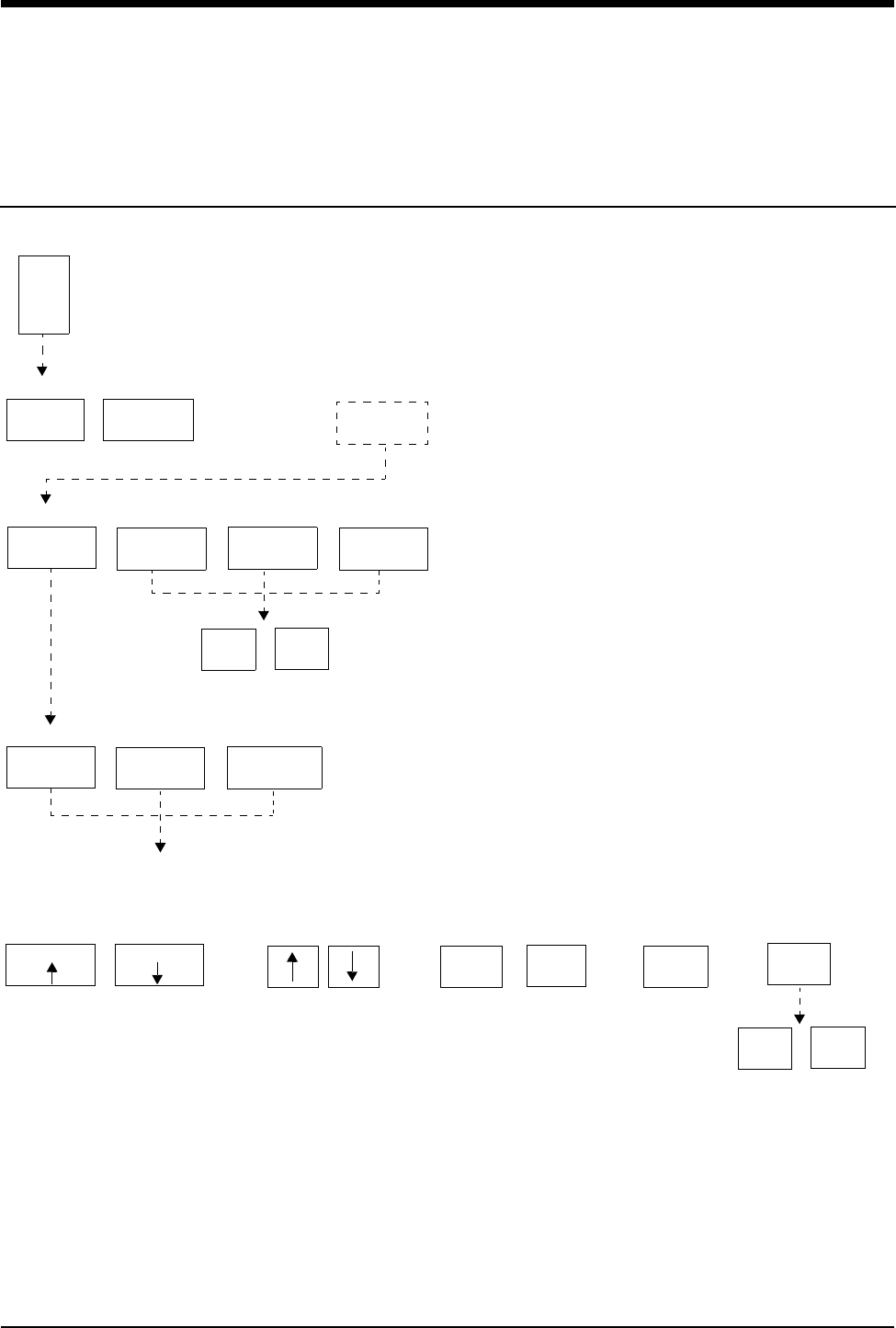
Module Configuration Manager
Directory
!
• Based on features purchased, more or fewer keys may appear here than on your menu screens.
7-2
Directory of Keys - For Configurations Without ECG
DEFAULT STORAGE MENU
USER
SETTINGS
TRANSFER
SETTINGS
RETRIEVE
SETTINGS
FACTORY
DEFAULTS
TEMP MENU
ALARM
LIMITS
RESTORE
SETTINGS HIDDEN
KEY
See your system
administrator for
access to this key
T
E
M
P
USER SETTINGS - CHANNEL SELECT
PRES SPO2 TEMP
User Settings screens appear here
(Refer to Display Detail)
YES NO
STORE
SELECT PARAMETER
CURSOR CURSOR
CHANGE VALUE PAGE X OF X
YES NO
PRINT
PAGE
NEXT
PAGE
PREV
PAGE
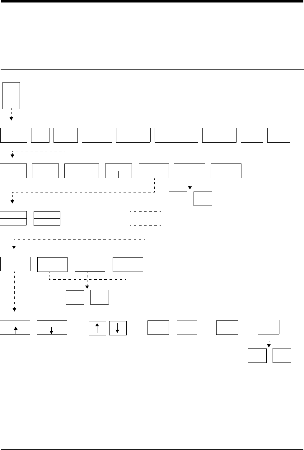
7-3
!
• Based on features purchased, more or fewer keys may appear here than on your menu screens.
Module Configuration Manager
Directory
Directory of Keys - For Telemetry Configurations
ECG MENU
ALARM
LIMITS SIZE SETUP LEAD
SELECT
CHANNEL
FORMAT
SUSPEND
PROCESSING REVIEWPRINTRELEARN
ECG - SETUP
SWEEP
SPEED
MONITOR
EXTENDED
QRS
TONE
RESTORE
SETTINGS
HIDDEN
KEY
ECG - CONFIG
INFANT
DEFAULT STORAGE MENU
USER
SETTINGS
TRANSFER
SETTINGS
RETRIEVE
SETTINGS
FACTORY
DEFAULTS
CONFIG
YES NO
See your system
administrator for
access to this key
TM
SETUP
E
C
G
PACED
YES NO
ADULT ARR
ON OFF
YES NO
PRINT
PAGE STORE
SELECT PARAMETER
CURSOR CURSOR NEXT
PAGE
PREV
PAGE
CHANGE VALUE PAGE X OF X
YES NO


Contents
7-5
Overview . . . . . . . . . . . . . . . . . . . . . . . . . . . . . . . . . . . . . . . . . . . . . . . . . . . . . . 5
Display Detail. . . . . . . . . . . . . . . . . . . . . . . . . . . . . . . . . . . . . . . . . . . . . . . . . . . 6
Setting User-Defined Default Values . . . . . . . . . . . . . . . . . . . . . . . . . . . . . . . . . 7
Storing Changed Settings . . . . . . . . . . . . . . . . . . . . . . . . . . . . . . . . . . . . . . . . . 7
Selecting Alarm Attributes . . . . . . . . . . . . . . . . . . . . . . . . . . . . . . . . . . . . . . . . . 7
Parameter Configurations . . . . . . . . . . . . . . . . . . . . . . . . . . . . . . . . . . . . . . . . . 8
Transferring User-Defined Settings . . . . . . . . . . . . . . . . . . . . . . . . . . . . . . . . . 33
Retrieving User-Defined Settings . . . . . . . . . . . . . . . . . . . . . . . . . . . . . . . . . . 33
Restoring Factory Settings . . . . . . . . . . . . . . . . . . . . . . . . . . . . . . . . . . . . . . . 34
Restoring User-Defined Settings . . . . . . . . . . . . . . . . . . . . . . . . . . . . . . . . . . . 34
Module Configuration Manager
Overview
The Module Configuration Manager feature provides the capability to define and
store all user-configurable options within your module. Once a module has been
configured, these settings will control its operation whenever the module is
powered ON.
To ensure standardization of multiple modules, settings may be transferred from
one configured module to another. Settings are first transferred from a configured
module to the monitor (using the TRANSFER SETTINGS key), then retrieved
from the monitor into other modules (using the RETRIEVE SETTINGS key).
The Restore Settings feature changes all the module’s parameter user-
configurable options to the defaults previously stored as user settings.
Depending on the parameter configuration of the module, the Module
Configuration Manager feature is accessible through either the ECG or TEMP
parameter key. For module configurations without ECG, use the TEMP key. For
module configurations with ECG, use the ECG key. (Refer to Module
Configuration Manager on page 15-23 for more information.)
!
• User-configurable parameters are available based on the
options in your module. For example, if your module does not
have the Arrhythmia Processing feature (Multiview™ I),
parameters related to arrhythmia detection and alarms will not
be available.
• User-defined settings which have been transferred to the
monitor’s memory are available for retrieval into other modules
until (1) the monitor is powered OFF or (2) a patient is admitted
or discharged with a purge of data.
!
• The TEMP key will only be displayed if a temperature probe is
connected to the module.
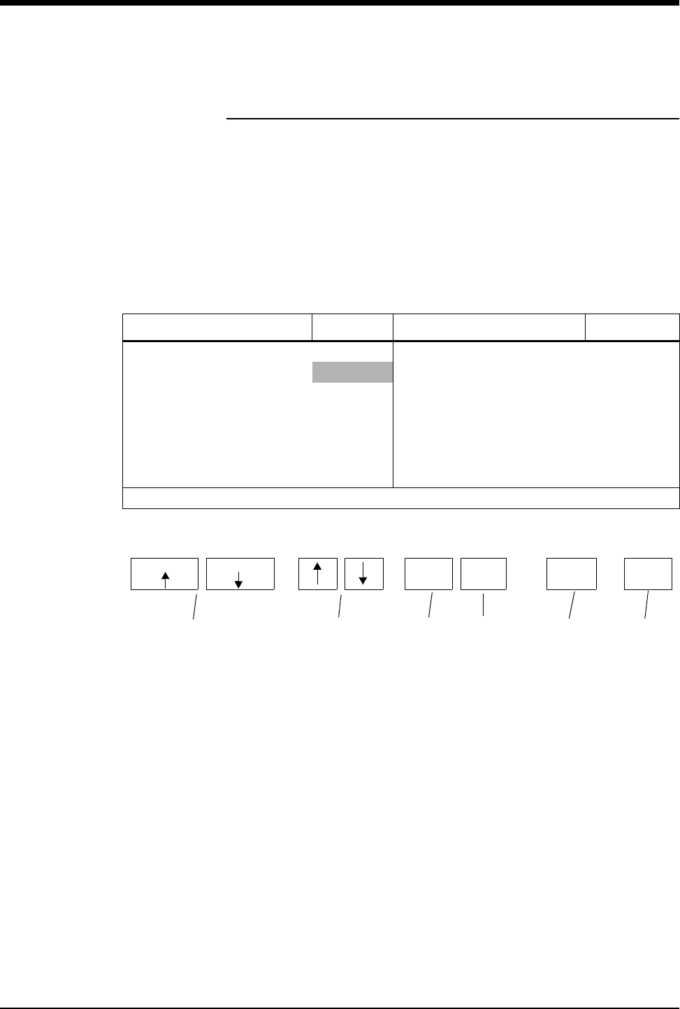
Ultraview Care Network
7-6
Display Detail
The User Settings screens list all user-configurable options for ECG, respiration,
Varitrend 3, temperature, invasive pressure, non-invasive blood pressure, and
SpO2. From these screens you can change and store the options in your module.
Figure 7-1 illustrates the ECG User Settings screen which is used to change and
store ECG rate alarm limits. In this example, LEARNED has been chosen as the
adult rate alarms type.
The parameter configuration tables in this chapter list all available options, the
available user settings, and the factory defaults for each parameter.
Figure 7-1: ECG user settings
CURSOR ↑ AND CURSOR ↓ keys scroll through the two columns of
parameters on the screen.
↑ and ↓ keys scroll the list of valid settings for the highlighted parameter.
PREV PAGE key returns to the previous screen.
NEXT PAGE key advances to the next screen.
PRINT PAGE key prints the current screen.
STORE key stores the currently selected settings as defaults.
PARAMETER DESCRIPTION VALUE PARAMETER DESCRIPTION VALUE
ECG RATE ALARMS (ADULT) ECG RATE ALARMS (INFANT)
• TYPE LEARNED • TYPE LEARNED
• HIGH RATE 180 • HIGH RATE 220
•LOW RATE 40 •LOW RATE 100
• HIGH RATE OFFSET 50 • HIGH RATE OFFSET 50
• LOW RATE OFFSET 50 • LOW RATE OFFSET 50
•DELAY 3
Set ECG alarm type to LEARNED or FIXED limits
STORE
SELECT PARAMETER
CURSOR CURSOR
CHANGE VALUE PAGE X OF X
PRINT
PAGE
NEXT
PAGE
PREV
PAGE

Module Configuration Manager
7-7
Setting User-Defined Default Values
Use the User Settings screens to change and store settings. If the setting for the
selected parameter cannot be changed, the message THIS SETTING CANNOT
BE CHANGED will be displayed.
The ability to access the Module Configuration Manager screens can either be
visible to all users or remain hidden. The factory default setting is Invisible. Adjust
the SYSTEM SETUP key to the Visible setting in the ECG configuration table to
enable user access to this function.
Storing Changed Settings
Touch the STORE key after entering configuration changes for any parameter in
the module. This action stores only the currently selected settings for all
parameters in that module.
The Patient Admit/Discharge function (available in the ECG configuration screen)
allows you to SAVE the changes in the alarm limit settings as the default settings
for future patients, or RESTORE the original default settings upon discharge of
that patient or admission of a new patient.
The Save setting is commonly used in environments where multiple patients are
monitored for short periods of time, for example, the operating room. Selecting
SAVE allows you to save specific settings from patient to patient until the module
is removed or the monitor is powered OFF.
The Restore setting is more commonly used in environments where it is desirable
to initialize alarm limit settings for each patient, for example, the critical care unit
or the intensive care unit. Selecting RESTORE returns the module to the default
settings upon patient admission or discharge.
Your selection on the ECG Configuration screen applies to all parameters.
Selecting Alarm Attributes
Alarms can be independently configured for all parameters including: tone types
(high, medium, low, or none), whether a specific alarm condition triggers an
automatic recording, or alarms are watched under the Alarm Watch feature.
In the Monitor Setup menu, individual parameters may be selected for automatic
alarm recording. If alarm recording is enabled for a particular parameter, for
example ECG, you can further specify which alarms will generate a recording.
You can also specify which alarms will be watched using the Alarm Watch feature.
For example, if you have selected a patient for Alarm Watch, but you do not want
to be alerted to LEAD OFF conditions remotely, select Alarm Watch OFF for that
condition in the corresponding Alarm Attributes screens. Refer to the Alarm
Attributes tables in this chapter for available user-defined settings and factory
defaults for the individual parameters.

Ultraview Care Network
7-8
Parameter Configurations
ECG
Heart rate alarms can be set to fixed values or based upon the patient’s learned
heart rate. The learned heart rate is known as a result of ECG monitoring. If the
learned option is selected, you must specify high and low offset values. The high
and low rate alarm limits specify boundaries of the maximum available settings.
To automatically set heart rate alarms to:
• 40 beats above and 40 beats below the patient's learned heart rate.
• not to exceed a high rate of 200 and a low rate of 30.
Adjust the default settings as follows:
When selecting the fixed option, you only need to adjust the high and low rate
settings.
Heart rate alarms can be set independently for the adult mode and the infant
mode.
In the infant mode, you can select a delay between the time of initiation of
monitoring and alarm activation (0- to 3-minutes). This provides a period of time
for the patient to calm down after electrode application.
ST alarms can be set to identify regional and global changes. Specific leads can
be selectively included or excluded to provide more specific information.
The Check Setup feature provides a visual and audible prompt for you to assess
the patient setup before initiating monitoring or following a monitor reset or ECG
module change. You can disable this feature by setting it to OFF.
If you do not want to suspend ECG processing or disable ECG alarms, set the
CONTROL setting to OFF.
Type Learned
HIGH RATE 200
LOW RATE 30
HIGH RATE OFFSET 40
LOW RATE OFFSET 40
To review or change settings:
1Touch ECG.
2Touch SETUP.
3Touch CONFIG.
4Touch the hidden key 3 times.
5Touch USER SETTINGS.
6a Select ECG.
-OR-
6b Select RESP.
-OR-
6c Select VARITREND.
-OR-
6d Select PRESSURE.
-OR-
6e Select SPO2.
-OR-
6f Select NIBP.
-OR-
6g Select TEMP.
7Use CURSOR↑ and CURSOR↓
to scroll through the parameter
description list.
8Use ↑ and ↓ to change the
settings.
9Touch NEXT PAGE to continue
to next screen of parameters.
10 Touch STORE to save the new
settings.
11 Touch YES when the STORE
ALL CHANNEL DEFAULTS
message is displayed

Module Configuration Manager
7-9
!
• For telemetry, some settings may or may not be available
depending on whether the module is used in a central or
bedside monitor.
• For Ultraview Digital Telemetry (multiparameter), default
settings for SpO2 and NIBP may be found as part of the ECG
channel. Telemetry ECG parameter configuration and alarm
attributes are found in separate tables in this chapter following
the tables for the hardwired (non-telemetry) products. Refer to
Table 1 and Table 2 for non-telemetry products. Refer to
Table 3 and Table 4 for telemetry products.
Table 1: ECG Parameter Configuration
Parameter Available User Settings Factory
Defaults
User
Settings
ECG Rate Alarms (Adult)
Rate Alarm Type Learned or fixed limits Learned
High Rate Alarm Limit 5 to 300 BPM 180 BPM
Low Rate Alarm Limit 0 to 200 BPM 40 BPM
High Rate Offset
(only applies to learned limits) 5 to 80 BPM 50 BPM
Low Rate Offset
(only applies to learned limits) 5 to 80 BPM 50 BPM
ECG Rate Alarms (Infant)
Rate Alarm Type Learned or fixed limits Fixed
High Rate Alarm Limit 5 to 300 BPM 220 BPM
Low Rate Alarm Limit 0 to 200 BPM 100 BPM
High Rate Offset
(only applies to learned limits) 5 to 80 BPM 50 BPM
Low Rate Offset
(only applies to learned limits) 5 to 80 BPM 50 BPM
Infant Alarm Delay
(for ECG and Resp alarms) 0- to 3-minutes 3-minutes
ECG Mode Adult/Infant Adult
Sweep Speed 50, 25, or 12.5 mm/sec. 25 mm/sec.
Respiration On/Off On
Varitrend On/Off Off
QRS Tone (local only) On/Off Off
QRS Volume (local only) 1 (soft) to 8 (loud) 4
SpO2 Pitch Modulation of
QRS Tone On/Off Off
Display Resolution Monitor/Extended Monitor

Ultraview Care Network
7-10
Arrhythmia Processing On/Off On
Abnormals in a Row 2 to 10 or Off 5
Abnormals/Minute 1 to 99 or Off Off
Review On/Off On
1st Lead Selection Limb, V, or augmented lead V2
1st Lead Waveform Size 2.00 mV/cm - 0.10 mV/cm 0.50 mV/cm
2nd Lead Selection Limb, V, or augmented lead II
2nd Lead Waveform Size 2.00 mV/cm - 0.10 mV/cm 0.50 mV/cm
ST Alarm (single lead) 0.00 mm (Off) to 9.00 mm 1.0 mm
ST Alarm (multi-lead) 0.00 mm (Off) to 8.75 mm 0.50 mm
ST Alarm (I) On/Off On
ST Alarm (II) On/Off On
ST Alarm (III) On/Off On
ST Alarm (AVR) On/Off On
ST Alarm (AVL) On/Off On
ST Alarm (AVF) On/Off On
ST Alarm (V1) On/Off On
ST Alarm (V2) On/Off On
ST Alarm (V3) On/Off On
ST Alarm (V4) On/Off On
ST Alarm (V5) On/Off On
ST Alarm (V6) On/Off On
Automatic Lead Switch On/Off On
Single Lead Alarm On/Off Off
Primary Rate Source ECG/ART/SPO2/UA ECG
Alternate Rate Source (ECG) On/Off On
Alternate Rate Source (ART) On/Off On
Alternate Rate Source (SPO2) On/Off On
Alternate Rate Source (UA) On/Off On
Enhanced Vital Signs On/Off Off
Display Format Full view, Split view, 2-lead,
1-lead, or Cascade 1-lead
Save ST Time Interval Off, 5-, 10-, 15-, 30-, or
60-minutes 15-minutes
Table 1: ECG Parameter Configuration (continued)
Parameter Available User Settings Factory
Defaults
User
Settings

Module Configuration Manager
7-11
ST Trend Scale
-5 to 0 mm
0 to 5 mm
-2 to 0 mm
0 to 2 mm
-1 to 1 mm
-2 to 2 mm
-5 to 5 mm
-10 to 10 mm
+/- 2.0 mm
ST Trend Timebase 1.5-, 3-, 6-, 12-, or 24-hours 6-hours
Real-Time ST Trend On/Off Off
Real-Time Trend Timebase 15- or 30-minutes 30-minutes
Auto Report Off; 30-minutes; 1-, 2-, 4-, 8-,
24-hours Off
Auto Print On/Off Off
Report Format Standard -1, Cabrera-1,
Standard-3, Cabrera-3 Standard-1
Send ECG Report Auto/Manual Auto
Check Setup On/Off On
Line Frequency 50 Hz, 60 Hz 60 Hz
Control On/Off On
Default Storage Key Visible/Invisible Invisible
Patient Admit/Discharge Save/Restore Restore
Select HLO Parameters ECG1/P1, ECG1/RESP,
ECG1/ECG2, P1/P2 ECG1/P1
Table 1: ECG Parameter Configuration (continued)
Parameter Available User Settings Factory
Defaults
User
Settings

Ultraview Care Network
7-12
Table 2: ECG Alarm Attributes
Alarm Type
Tone Type Alarm Recording Alarm Watch
Available User Settings
Factory Defaults
User Settings
Available User Settings
Factory Defaults
User Settings
Available User Settings
Factory Defaults
User Settings
Asystole H H H Y Y Y Y Y Y
VFIB H H H Y Y Y Y Y Y
High Rate H,M,L,N H Y,N Y Y,N Y
Low Rate H,M,L,N H Y,N Y Y,N Y
Run H,M,L,N H Y,N Y Y,N Y
Couplet H,M,L,N M Y,N Y Y,N Y
Ta c h H , M , L , N M Y, N Y Y, N Y
ABN/MIN H,M,L,N M Y,N Y Y,N Y
ST Single-lead H,M,L,N M Y,N Y Y,N Y
ST Multi-lead H,M,L,N M Y,N Y Y,N Y
Classes Full H,M,L,N L N N N Y,N N
CH 1 & 2 Lead Off H,M,L,N M N N N Y,N Y
CH 1 Lead Off H,M,L,N M N N N Y,N Y
CH 2 Lead Off H,M,L,N M N N N Y,N Y
Low Voltage H,M,L,N M N N N Y,N Y
Noisy Signal H,M,L,N L N N N Y,N N
HR Unavailable H,M,L,N M N N N Y,N Y
H = High; M = Medium; L = Low; N = None; Y = Yes; N = No

Module Configuration Manager
7-13
!
• Alarm attributes for asystole and ventricular fibrillation cannot
be changed.
- If ECG alarms are enabled, episodes of asystole and
ventricular fibrillation will always trigger a high alarm tone.
- If ECG alarm recording is enabled, asystole and ventricular
fibrillation will always trigger a recording.
- If Alarm Watch is enabled for a patient, asystole and
ventricular fibrillation will always trigger an alarm
notification.
• Setting tone type to NONE automatically sets alarm recording
and alarm watch to NO for that alarm. Changing tone type from
NONE to any other setting returns alarm recording and alarm
watch to factory defaults.
• Setting tone type to NONE for high rate, low rate, ABN/MIN, or
run causes the affected alarm limit to be displayed in reverse
video in the ECG display zone.
Table 3: ECG Parameter Configuration (Telemetry Only)
Parameter Available User Settings Factory
Defaults
User
Settings
ECG Rate Alarms (Adult) On On On
Rate Alarm Type Learned/Fixed Learned
High Rate Alarm Limit 5 to 300 BPM 180 BPM
Low Rate Alarm Limit 0 to 200 BPM 40 BPM
High Rate Offset
(only applies to learned limits) 5 to 80 BPM 50 BPM
Low Rate Offset
(only applies to learned limits) 5 to 80 BPM 50 BPM
ECG Rate Alarms (Infant) On On On
Rate Alarm Type Learned/Fixed Learned
High Rate Alarm Limit 5 to 300 BPM 220 BPM
Low Rate Alarm Limit 0 to 200 BPM 100 BPM
High Rate Offset
(only applies to learned limits) 5 to 80 BPM 50 BPM
Low Rate Offset
(only applies to learned limits) 5 to 80 BPM 50 BPM
Infant Alarm Delay
(for ECG and Resp alarms) 0- to 3-minutes 3-minutes
2nd Lead Display On/Off Off
ECG Mode Adult/Infant Adult
Sweep Speed 50, 25, or 12.5 mm/sec. 25 mm/sec.
Enhanced Vital Signs On/Off Off
ST Trend Timebase 1.5-, 3-, 6-, 12-, or 24-hours 6-hours

Ultraview Care Network
7-14
QRS Tone (local only) On/Off Off
QRS Volume (local only) 1 (soft) to 8 (loud) 4
SpO2 Pitch Modulation of QRS Tone On/Off Off
Display Resolution Monitor/Extended Monitor
Arrhythmia Processing On/Off On
Abnormals in a Row 2 to 10 or Off 5
Abnormals/Minute 1 to 99 or Off Off
Review On/Off On
1st Lead Selection Limb, V, augmented or MCL lead VI
1st Lead Waveform Size 2.00 mV/cm - 0.10 mV/cm 0.5 mV/cm
2nd Lead Selection Limb, V, augmented or MCL lead II
2nd Lead Waveform Size 2.00 mV/cm - 0.10 mV/cm 0.5 mV/cm
ST Level Alarm (channel 1) On/Off Off
ST Level Alarm Type Learned/Fixed Learned
High Level Alarm Limit
(only applies to fixed limits) -8.75 mm to 9.00 mm 1.00 mm
Low Level Alarm Limit
(only applies to fixed limits) -9.00 mm to 8.75 mm - 1.00 mm
High Level Offset
(only applies to learned limits) 0.25 mm to 9.00 mm 1.00 mm
Low Level Offset
(only applies to learned limits) 0.25 mm to 9.00 mm 1.00 mm
ST Change Alarm (channel 1) On/Off Off
Max-Min. Change Within 5-Minutes
(delta) 0.25 mm to 9.00 mm 1.00 mm
ST Level Alarm (channel 2) On/Off Off
ST Level Alarm Type Learned/Fixed Learned
High Level Alarm Limit
(only applies to fixed limits) -8.75 mm to 9.00 mm 1.00 mm
Low Level Alarm Limit
(only applies to fixed limits) -9.00 mm to 8.75 mm - 1.00 mm
High Level Offset
(only applies to learned limits) 0.25 mm to 9.00 mm 1.00 mm
Low Level Offset
(only applies to learned limits) 0.25 mm to 9.00 mm 1.00 mm
ST Change Alarm (channel 2) On/Off Off
Max-Min. Change Within 5-Minutes
(delta) 0.25 mm to 9.00 mm 1.00 mm
Check Setup Key On/Off On
Line Frequency 50 Hz, 60 Hz 60 Hz
Table 3: ECG Parameter Configuration (Telemetry Only) (continued)
Parameter Available User Settings Factory
Defaults
User
Settings

Module Configuration Manager
7-15
Control (controls ALARM ON/OFF
and SUSPEND PROCESSING
keys)
On/Off On
Automatic Lead Switch On/Off On
Single Lead Alarm On/Off Off
Default Storage Key Visible/Invisible Invisible
Low Battery Alarm On/Off On
Patient Record On/Off Off
Telemetry Bed Assignment Temporary/Permanent Temporary
Patient Admit/Discharge Save/Restore Restore
Frequency Band
North America UHF, North
America VHF, European
Telecom, United Kingdom,
Australia, Spain, Sweden,
Finland, New Zealand, Norway,
Singapore, South Africa
North America
UHF
Primary Heart Rate Source ECG/ART/SPO2/UA ECG
Alternate Rate Source (ECG) On/Off On
Alternate Rate Source (ART) On/Off On
Alternate Rate Source (SPO2) On/Off On
Alternate Rate Source (UA) On/Off On
Multiparameter Telemetry On/Off On
Telemetry SpO2 Alarms
(only if multiparameter is On) On On On
SpO2 High Limit
(only if multiparameter is On) 51% - 100% 100%
SpO2 Low Limit
(only if multiparameter is On) 50% - 99% 85%
SpO2 Limit Alarm Delay
(only if multiparameter is On) 0- to 30-seconds 15-seconds
SpO2 Message Alarm Delay
(only if multiparameter is On) 0- to 60-seconds 20-seconds
Telemetry NIBP Alarms
(only if multiparameter is On) On On On
NIBP Systolic High Limit
(only if multiparameter is On) 35 to 260 mmHg 150 mmHg
NIBP Systolic Low Limit
(only if multiparameter is On) 30 to 255 mmHg 100 mmHg
NIBP Diastolic High Limit
(only if multiparameter is On) 35 to 260 mmHg 100 mmHg
Table 3: ECG Parameter Configuration (Telemetry Only) (continued)
Parameter Available User Settings Factory
Defaults
User
Settings

Ultraview Care Network
7-16
NIBP Diastolic Low Limit
(only if multiparameter is On) 30 to 255 mmHg 60 mmHg
NIBP Mean High Limit
(only if multiparameter is On) 35 to 260 mmHg 110 mmHg
NIBP Mean Low Limit
(only if multiparameter is On) 30 to 255 mmHg 90 mmHg
!
• Multiparameter telemetry displays ECG, SpO2, and NIBP data
all in the ECG channel. Alarm messages are displayed in order
of priority.
Table 4: ECG Alarm Attributes (Telemetry Only)
Alarm Type
Tone Type Alarm Recording Alarm Watch
Available User Settings
Factory Defaults
User Settings
Available User Settings
Factory Defaults
User Settings
Available User Settings
Factory Defaults
User Settings
Asystole H H H Y Y Y Y Y Y
VFIB H HHYYYYYY
High Rate H,M,L,N H Y,N Y Y,N Y
Low Rate H,M,L,N H Y,N Y Y,N Y
Run H,M,L,N H Y,N Y Y,N Y
Couplet H,M,L,N M Y,N Y Y,N Y
Tach H , M ,L,N M Y,N Y Y,N Y
ABN/MIN H,M,L,N M Y,N Y Y,N Y
ST High/Low H,M,L,N M Y,N Y Y,N Y
ST Change H,M,L,N M Y,N Y Y,N Y
Classes Full H,M,L,N L N N N Y,N N
CH 1 & 2 Lead Off H,M,L,N M N N N Y,N Y
CH 1 Lead Off H,M,L,N M N N N Y,N Y
CH 2 Lead Off H,M,L,N M N N N Y,N Y
Low Voltage H,M,L,N M N N N Y,N Y
Table 3: ECG Parameter Configuration (Telemetry Only) (continued)
Parameter Available User Settings Factory
Defaults
User
Settings

Module Configuration Manager
7-17
Noisy Signal H,M,L,N L N N N Y,N N
Squelch H,M,L,N L N N N Y,N N
Signal Interference H,M,L,N L N N N Y,N N
Low Battery H,M,L,N L N N N Y,N N
SpO2 Monitor Fail H,M,L,N L N N N N
SpO2 High Limit H,M,L,N L Y,N N Y,N N
SpO2 Low Limit H,M,L,N L Y,N N Y,N N
SpO2 Faulty Sensor H,M,L,N L N N N N
SpO2 Sensor Disconnected H,M,L,N L N N N N
SpO2 Ambient Light Intf. H,M,L,N L N N N N
SpO2 Sensor Off Patient H,M,L,N L N N N N
SpO2 Insufficient Signal H,M,L,N L N N N N
SpO2 Noisy Signal H,M,L,N L N N N N
NIBP Cable Disconnected H,M,L,N L N N N N
NIBP Unavailable (xx) H,M,L,N L N N N N
NIBP Reading Failure (xx) H,M,L,N L N N N N
NIBP Air Leak H,M,L,N L N N N N
NIBP Loose or No Cuff H,M,L,N L N N N N
NIBP Patient Cancelled H,M,L,N L N N N N
NIBP Low Battery H,M,L,N L N N N N
NIBP Low Battery Backup H,M,L,N L N N N N
NIBP Kinked Hose H,M,L,N L N N N N
NIBP Event Code (xx) H,M,L,N L N N N N
NIBP Sys High Limit H,M,L,N L Y,N N Y,N N
NIBP Sys Low Limit H,M,L,N L Y,N N Y,N N
NIBP Dia High Limit H,M,L,N L Y,N N Y,N N
NIBP Dia High Limit H,M,L,N L Y,N N Y,N N
Table 4: ECG Alarm Attributes (Telemetry Only) (continued)
Alarm Type
Tone Type Alarm Recording Alarm Watch
Available User Settings
Factory Defaults
User Settings
Available User Settings
Factory Defaults
User Settings
Available User Settings
Factory Defaults
User Settings

Ultraview Care Network
7-18
NIBP Mean High Limit H,M,L,N L Y,N N Y,N N
NIBP Mean Low Limit H,M,L,N L Y,N N Y,N N
H = High; M = Medium; L = Low; N = None; Y = Yes; N = No
!
• Messages and alarms beginning with “SPO2” or “NIBP” apply
only when the Ultraview Multiparameter Digital Telemetry
transmitter is used and multiparameter operation is enabled by
the MCM Multiparameter Telemetry ON setting. Refer to
Multiparameter Telemetry Overview on page 17-5 for more
information.
• Alarm attributes for asystole and ventricular fibrillation cannot
be changed.
- If ECG alarms are enabled, episodes of asystole and
ventricular fibrillation will always trigger a high alarm tone.
- If ECG alarm recording is enabled, asystole and ventricular
fibrillation will always trigger a recording.
- If Alarm Watch is enabled for a patient, asystole and
ventricular fibrillation will always trigger an alarm
notification.
• Setting tone type to NONE automatically sets alarm recording
and alarm watch to NO for that alarm. Changing tone type from
NONE to any other setting returns alarm recording and alarm
watch to factory defaults.
• Setting tone type to NONE for high rate, low rate, ABN/MIN, or
run causes the affected alarm limit to be displayed in reverse
video in the ECG display zone.
Table 4: ECG Alarm Attributes (Telemetry Only) (continued)
Alarm Type
Tone Type Alarm Recording Alarm Watch
Available User Settings
Factory Defaults
User Settings
Available User Settings
Factory Defaults
User Settings
Available User Settings
Factory Defaults
User Settings

Module Configuration Manager
7-19
Respiration
Respiration alarms can be set independently for the adult and infant mode. In the
adult mode, respiratory rate alarms can be set as determined following initiation of
respiratory monitoring. If you select the learned option, the high rate alarm limit is
set at 1.5 times the learned rate. The low rate alarm limit is set to 0. The high limit
is never automatically set above 150 breaths per minute (BPM) or lower than
30 BPM in the learned model.
!
• Respiratory rate and apnea alarms cannot be disabled in the
infant mode.
Table 5: Respiration Parameter Configuration
Parameter Available User
Settings
Factory
Defaults
User
Settings
Rate Alarms (Adult) On/Off Off
High Rate Alarm Type Learned/Fixed Learned
High Rate Alarm Limit
(only applies to fixed limits) 1 to 200 breaths/min. 50 breaths/min.
Low Rate Alarm Limit
(only applies to fixed limits) 0 to 195 breaths/min. 0
Apnea Alarm On/Off Off
Apnea Duration 5- to 40-seconds 20-sec.
Breathing Pattern Shallow/Normal Normal
Rate Alarms (Infant) On On On
High Rate Alarm Type Learned/Fixed Fixed
High Rate Alarm Limit 1 to 200 breaths/min. 100 breaths/min.
Low Rate Alarm Limit 0 to 195 breaths/min. 10 breaths/min.
Apnea Alarm On On On
Apnea Duration 5- to 40-seconds 20-sec.
Breathing Pattern Shallow/Normal Shallow
Waveform Display On/Off On
Waveform Size 2.00 - 0.10 ohms/cm 1.00 ohms/cm
CVA Filter On/Off On
Lead Selection RA-LA, RL-LA, RA-LL,
RL-LL RA-LA
Sweep Speed 25,12.5, 6.25 or 1.56
mm/sec. 12.5 mm/sec.
Breath Tone
(local only) On/Off Off
Breath Tone Volume
(local only) 1 (soft) to 8 (loud) 3
To review or change Respiration
settings:
1Touch ECG.
2Touch SETUP.
3Touch CONFIG.
4Touch the hidden key three
times.
5Touch USER SETTINGS.
6Select RESP.
7Use CURSOR↑ and CURSOR↓
to scroll through the parameter
description list.
8Use ↑ and ↓ to change the
settings.
9Touch NEXT PAGE to continue
to next screen of parameters.
10 Touch STORE to save the new
settings.
11 Touch YES when the STORE
ALL CHANNEL DEFAULTS
message is displayed.

Ultraview Care Network
7-20
Table 6: Respiration Alarm Attributes
Alarm Type
Tone Type Alarm Recording Alarm Watch
Available User Settings
Factory Defaults
User Settings
Available User Settings
Factory Defaults
User Settings
Available User Settings
Factory Defaults
User Settings
Apnea H H H Y Y Y Y Y Y
High Rate H,M,L,N M Y,N Y Y,N Y
Low Rate H,M,L,N M Y,N Y Y,N Y
Loss of
Signal H,M,L,N M N N N Y,N Y
H = High; M = Medium; L = Low; N = None; Y = Yes; N = No
!
• Alarms attributes for apnea cannot be changed.
- If RESP alarms are enabled, episodes of apnea will always
trigger a high alarm tone.
- If RESP alarm recording is enabled, apnea will always
trigger a recording.
- If Alarm Watch is enabled for a patient, apnea will always
trigger an alarm notification.
• Setting tone type to NONE automatically sets alarm recording
and alarm watch to NO for that alarm. Changing tone type from
NONE to any other setting returns alarm recording and alarm
watch to factory defaults.
• Setting tone type to NONE for high rate or low rate alarms
causes the affected alarm limit to be displayed in reverse video
in the RESP display zone.

Module Configuration Manager
7-21
Varitrend® 3
Default settings and individual parameter scales for the Varitrend timebase and
display are adjustable. Definitions for up to five events can be pre-selected to
describe concurrent changes in heart rate, respiration rate, or saturation level that
may be of specific clinical interest.
Table 7: Varitrend 3 Parameter Configuration
Parameter Available User Settings Factory
Defaults
User
Settings
Trend Timebase 1.5 min. or 3.0 min. 1.5 min.
Resp Display Rate or waveform Waveform
Resp Waveform Size
+/- 0.3 ohms
+/- 0.5 ohms
+/- 1.0 ohms
+/- 2.0 ohms
+/- 6.0 ohms
+/- 2.0 ohms
Resp Rate Scale
AUTOSCALE
0 to 50
0 to100
0 to150
0 to 200
AUTOSCALE
Heart Rate Scale
AUTOSCALE
0 to100
0 to150
50 to150
0 to 200
100 to 200
0 to 250
100 to 250
0 to 300
100 to 300
AUTOSCALE
SpO2 Scale
AUTOSCALE
0 to100
25 to100
50 to100
75 to100
AUTOSCALE
Auto Alarm
Recording On/Off Off
Bradycardia Limit
(event 1) 0 to150 BPM or Off Off
Tachycardia Limit
(event 1) 100 to 300 BPM or Off Off
Apnea Limit (event 1) 10- to 40-seconds or Off Off
SpO2 Limit (event 1) 25 to 95% or Off Off
Bradycardia Limit
(event 2) 0 to150 BPM or Off Off
Tachycardia Limit
(event 2) 100 to 300 BPM or Off Off
Apnea Limit (event 2) 10- to 40-seconds or Off Off
To review or change Varitrend 3
settings:
1Touch ECG.
2Touch SETUP.
3Touch CONFIG.
4Touch the hidden key 3 times.
5Touch USER SETTINGS.
6Select VARITREND.
7Use CURSOR↑ and CURSOR↓
to scroll through the parameter
description list.
8Use ↑ and ↓ to change the
settings.
9Touch NEXT PAGE to continue
to next screen of parameters.
10 Touch STORE to save the new
settings.
11 Touch YES when the STORE
ALL CHANNEL DEFAULTS
message is displayed.

Ultraview Care Network
7-22
SpO2 Limit (event 2) 25 to 95% or Off Off
Bradycardia Limit
(event 3) 0 to150 BPM or Off Off
Tachycardia Limit
(event 3) 100 to 300 BPM or Off Off
Apnea Limit (event 3) 10- to 40-seconds or Off Off
SpO2 Limit (event 3) 25 to 95% or Off Off
Bradycardia Limit
(event 4) 0 to150 BPM or Off Off
Tachycardia Limit
(event 4) 100 to 300 BPM or Off Off
Apnea Limit (event 4) 10- to 40-seconds or Off Off
SpO2 Limit (event 4) 25 to 95% or Off Off
Bradycardia Limit
(event 5) 0 to150 BPM or Off Off
Tachycardia Limit
(event 5) 100 to 300 BPM or Off Off
Apnea Limit (event 5) 10- to 40-seconds or Off Off
SpO2 Limit (event 5) 25 to 95% or Off Off
Table 7: Varitrend 3 Parameter Configuration
Parameter Available User Settings Factory
Defaults
User
Settings

Module Configuration Manager
7-23
Non-Invasive Blood Pressure
Non-invasive blood pressure (NIBP) alarms can be set independently for the adult
and infant modes. Default settings for systolic, diastolic and mean alarm limits are
fully adjustable within the specified ranges.
To have measurements automatically initiated at regular intervals, you can select
from the list of AUTO INTERVALS. After connecting a cuff to the patient, set
AUTO to ON in the NIBP menu and NIBP measurements will be automatic.
Table 8: NIBP Parameter Configurations
Parameter Available User
Settings Factory Defaults User
Settings
Systolic Alarm (Adult) On/Off Off
High Alarm Limit 45 to 260 mmHg 150 mmHg
Low Alarm Limit 40 to 255 mmHg 100 mmHg
Diastolic Alarm (Adult) On/Off Off
High Alarm Limit 45 to 260 mmHg 100 mmHg
Low Alarm Limit 40 to 255 mmHg 60 mmHg
Mean Alarm (Adult) On/Off Off
High Alarm Limit 45 to 260 mmHg 110 mmHg
Low Alarm Limit 40 to 255 mmHg 90 mmHg
Systolic Alarm (Infant) On/Off Off
High Alarm Limit 15 to 150 mmHg 85 mmHg
Low Alarm Limit 10 to 145 mmHg 55 mmHg
Diastolic Alarm (Infant) On/Off Off
High Alarm Limit 15 to 150 mmHg 75 mmHg
Low Alarm Limit 10 to 145 mmHg 45 mmHg
Mean Alarm (Infant) On/Off Off
High Alarm Limit 15 to 150 mmHg 80 mmHg
Low Alarm Limit 10 to 145 mmHg 50 mmHg
NIBP Mode Adult/Neonate Adult
Display Pulse Rate Yes/No Yes
Auto Interval
1- to 10-minutes by 1
15- to 55-minutes by 5
1-, 2-, 4-, or 8-hours
15-minutes
To review or change NIBP
settings:
1Touch ECG.
2Touch SETUP.
3Touch CONFIG.
4Touch the hidden key 3 times.
5Touch USER SETTINGS.
6Select NIBP.
7Use CURSOR↑ and CURSOR↓
to scroll through the parameter
description list.
8Use ↑ and ↓ to change the
settings.
9Touch NEXT PAGE to continue
to next screen of parameters.
10 Touch STORE to save the new
settings.
11 Touch YES when the STORE
ALL CHANNEL DEFAULTS
message is displayed.

Ultraview Care Network
7-24
Table 9: NIBP Alarm Attributes
Alarm Type
Tone Type Alarm Recording Alarm Watch
Available User Settings
Factory Defaults
User Settings
Available User Settings
Factory Defaults
User Settings
Available User Settings
Factory Defaults
User Settings
Systolic H,M,L,N M Y,N N Y,N N
Diastolic H,M,L,N M Y,N N Y,N N
Mean H,M,L,N M Y,N N Y,N N
No Reading H,M,L,N N Y,N N Y,N N
System Fault H,M,L,N L Y,N N Y,N N
Remove Cuff H,M,L,N H Y,N N Y,N Y
H = High; M = Medium; L = Low; N = None; Y = Yes; N = No

Module Configuration Manager
7-25
Temperature
Default settings for high and low temperature alarm limits are adjustable, as well
as the settings for the delta temperature.
Table 10: Temperature Parameter Configuration
Parameter Available User
Settings Factory Defaults User
Settings
Temperature 1 Alarms On/Off Off
High Alarm Limit 0.1° - 50.0°C 37.5°C
Low Alarm Limit 0.0° - 49.9°C 36.5°C
Temperature 2 Alarms On/Off Off
High Alarm Limit 0.1° - 50.0°C 37.5°C
Low Alarm Limit 0.0° - 49.9°C 36.5°C
Delta Alarms On/Off Off
High Alarm Limit 0.1° - 50.0°C 2.0°C
Low Alarm Limit 0.0° - 49.9°C 0.0°C
Default Storage Key Visible/Invisible Invisible
Patient
Admit/Discharge Save/Restore Restore
Table 11: Temperature Alarm Attributes
Alarm Type
Tone Type Alarm Recording Alarm Watch
Available User Settings
Factory Defaults
User Settings
Available User Settings
Factory Defaults
User Settings
Available User Settings
Factory Defaults
User Settings
T1 High Limit H,M,L,N L Y,N N Y,N N
T1 Low Limit H,M,L,N L Y,N N Y,N N
T2 High Limit H,M,L,N L Y,N N Y,N N
T2 Low Limit H,M,L,N L Y,N N Y,N N
DT High Limit H,M,L,N L Y,N N Y,N N
DT Low Limit H,M,L,N L Y,N N Y,N N
H = High; M = Medium; L = Low; N = None; Y = Yes; N = No
!
• Setting the tone type to NONE automatically sets the alarm
recording and alarm watch to NO for that alarm. Changing the
tone type from NONE to any other setting returns the alarm
recording and alarm watch to the factory defaults.
To review or change
Temperature settings:
Module Configurations with ECG
1Touch ECG.
2Touch SETUP.
3Touch CONFIG.
4Touch the hidden key 3 times.
5Touch USER SETTINGS.
6Select TEMP.
7Use CURSOR↑ and
CURSOR↓ to scroll through the
parameter description list.
8Use ↑ and ↓ to change the
settings.
9Touch STORE to save the new
settings.
10 Touch YES when the STORE
ALL CHANNEL DEFAULTS
message is displayed.
Module Configurations without
ECG
1Touch TEMP.
2Refer to steps 4 through 10
above.

Ultraview Care Network
7-26
Invasive Pressure
Invasive pressure parameters can be independently configured for each of two or
four pressure channels. The alarm type must be set to Fixed for the user-defined
alarm limit settings to be functional for high and low pressure alarm limits. If the
alarm type is set to the Learned mode, high and low alarm limits are set according
to the patient’s learned pressure.
The factory default label is:
• ART for the first pressure channel label
• PA for the second pressure channel
• PRS for the third channel
• CVP for the fourth channel
The associated alarm limit defaults correspond to typical pressure values for the
respective catheter site.
Table 12: Pressure Parameter Configuration Table (Channel 1)
Parameter Available User Settings Factory Defaults User
Settings
Label (P1) I C P, L A P, R A P, C V P, PA ,
ART, UA, UV, PRS ART
Scales On/Off Off
Top of Scale 10 to 500 mmHg or Auto 200 mmHg
Filter Frequency
3, 8, 12, 15, 18, 21, 25,
30, 35,
40 Hz
12 Hz
Sweep Speed 50, 25, 12.5, 6.25
mm/sec., or same as ECG same as ECG
Artifact Rejection On/Off Off
Numeric Size
Sys/Dia Large
Mean Large
All Large
Sys/Dia
Large
Alarm Type Learned/Fixed Learned
Systolic Alarm On/Off Off
High Alarm Limit -45 to 300 mmHg or Off 180 mmHg
Low Alarm Limit -50 to 295 mmHg or Off 100 mmHg
Diastolic Alarm On/Off Off
High Alarm Limit -45 to 300 mmHg or Off 120 mmHg
Low Alarm Limit -50 to 295 mmHg or Off 60 mmHg
Mean Alarm On/Off Off
High Alarm Limit -45 to 300 mmHg or Off 130 mmHg
Low Alarm Limit -50 to 295 mmHg or Off 80 mmHg
CPP Alarm On/Off Off
High Alarm Limit -45 to 300 mmHg or Off 50 mmHg
Low Alarm Limit -50 to 295 mmHg or Off 0 mmHg
To review or change Invasive
Pressure settings:
Module Configurations with ECG
1Touch ECG.
2Touch SETUP.
3Touch CONFIG.
4Touch the hidden key 3 times.
5Touch USER SETTINGS.
6Select PRESSURE.
7Use CURSOR↑ and CURSOR↓
to scroll through the parameter
description list.
8Use ↑ and ↓ to change the
settings.
9Touch NEXT PAGE to continue
to next screen of parameters.
10 Touch STORE to save the new
settings.
11 Touch YES when the STORE
ALL CHANNEL DEFAULTS is
displayed.
Module Configurations without
ECG
1Touch TEMP.
2Refer to steps 4 though 10
above.

Module Configuration Manager
7-27
Table 13: Pressure Parameter Configuration Table (Channel 2)
Parameter Available User Settings Factory Defaults User
Settings
Label (P2) I C P, LAP, R A P, C V P, PA , ART,
UA, UV, or PRS PA
Scales On/Off/Auto Off
Top of Scale 10 to 500 mmHg 50 mmHg
Filter Frequency 3, 8, 12, 15, 18, 21, 25, 30, 35,
40 Hz 12 Hz
Sweep Speed 50, 25, 12.5, 6.25 mm/sec., or
same as ECG Same as ECG
Artifact Rejection On/Off On
Numeric Size
Systolic/Diastolic Large
Mean Large
All Large
Systolic/Diastolic
Large
Alarm Type Learned/Fixed Learned
Systolic Alarm On/Off Off
High Alarm Limit -45 to 300 mmHg or Off 50 mmHg
Low Alarm Limit -50 to 295 mmHg or Off 10 mmHg
Diastolic Alarm On/Off Off
High Alarm Limit -45 to 300 mmHg or Off 20 mmHg
Low Alarm Limit -50 to 295 mmHg or Off 0 mmHg
Mean Alarm On/Off Off
High Alarm Limit -45 to 300 mmHg or Off 20 mmHg
Low Alarm Limit -50 to 295 mmHg or Off 5 mmHg
CPP Alarm On/Off Off
High Alarm Limit -45 to 300 mmHg or Off 50 mmHg
Low Alarm Limit -50 to 295 mmHg or Off 0 mmHg

Ultraview Care Network
7-28
Table 14: Invasive Pressure Parameter Configuration (Channel 3)
Parameter Available User Settings Factory Defaults User
Settings
Label (P3) I C P, L A P, R A P, C V P, PA , A R T,
UA, UV, or PRS PRS
Scales On/Off/Auto Off
Top of Scale 10 to 500 mmHg 200 mmHg
Filter Frequency 3, 8, 12, 15, 18, 21, 25, 30, 35, 40
Hz 12 Hz
Sweep Speed 50, 25, 12.5, 6.25 mm/sec., or
same as ECG Same as ECG
Artifact Rejection On/Off Off
Numeric Size
Systolic/Diastolic Large
Mean Large
All Large
Systolic/Diastolic
Large
Alarm Type Learned/Fixed Learned
Systolic Alarm On/Off Off
High Alarm Limit -45 to 300 mmHg or Off 180 mmHg
Low Alarm Limit -50 to 295 mmHg or Off 100 mmHg
Diastolic Alarm On/Off Off
High Alarm Limit -45 to 300 mmHg or Off 120 mmHg
Low Alarm Limit -50 to 295 mmHg or Off 60 mmHg
Mean Alarm On/Off Off
High Alarm Limit -45 to 300 mmHg or Off 130 mmHg
Low Alarm Limit -50 to 295 mmHg or Off 80 mmHg
CPP Alarm On/Off Off
High Alarm Limit -45 to 300 mmHg or Off 50 mmHg
Low Alarm Limit -50 to 295 mmHg or Off 0 mmHg

Module Configuration Manager
7-29
Table 15: Pressure Parameter Configuration Table (Channel 4)
Parameter Available User Settings Factory Defaults User
Settings
Label (P4) I C P, L A P, R A P, CVP, PA , ART, U A ,
UV, or PRS CVP
Scales On/Off/Auto Off
Top of Scale 10 to 500 mmHg 50 mmHg
Filter Frequency 3, 8, 12, 15, 18, 21, 25, 30, 35,
40 Hz 12 Hz
Sweep Speed 50, 25, 12.5, 6.25 mm/sec, or
same as ECG Same as ECG
Artifact Rejection On/Off Off
Numeric Size
Systolic/Diastolic Large
Mean Large
All Large
Systolic/Diastolic
Large
Alarm Type Learned/Fixed Learned
Systolic Alarm On/Off Off
High Alarm Limit -45 to 300 mmHg or Off 50 mmHg
Low Alarm Limit -50 to 295 mmHg or Off 10 mmHg
Diastolic Alarm On/Off Off
High Alarm Limit -45 to 300 mmHg or Off 20 mmHg
Low Alarm Limit -50 to 295 mmHg or Off 0 mmHg
Mean Alarm On/Off Off
High Alarm Limit -45 to 300 mmHg or Off 20 mmHg
Low Alarm Limit -50 to 295 mmHg or Off 5 mmHg
CPP Alarm On/Off Off
High Alarm Limit -45 to 300 mmHg or Off 50 mmHg
Low Alarm Limit -50 to 295 mmHg or Off 0 mmHg

Ultraview Care Network
7-30
Table 16: Invasive Pressure Alarm Attributes
Alarm Type
Tone Type Alarm Recording Alarm Watch
Available User Settings
Factory Defaults
User Settings
Available User Settings
Factory Defaults
User Settings
Available User Settings
Factory Defaults
User Settings
CH1 Systolic H,M,L,N H Y,N Y Y,N Y
CH1 Diastolic H,M,L,N H Y,N Y Y,N Y
CH1 Mean H,M,L,N H Y,N Y Y,N Y
CH1 CCP H,M,L,N H Y,N Y Y,N Y
CH2 Systolic H,M,L,N H Y,N Y Y,N Y
CH2 Diastolic H,M,L,N H Y,N Y Y,N Y
CH2 Mean H,M,L,N H Y,N Y Y,N Y
CH2 CCP H,M,L,N H Y,N Y Y,N Y
CH3 Systolic H,M,L,N H Y,N Y Y,N Y
CH3 Diastolic H,M,L,N H Y,N Y Y,N Y
CH3 Mean H,M,L,N H Y,N Y Y,N Y
CH3 CCP H,M,L,N H Y,N Y Y,N Y
CH4 Systolic H,M,L,N H Y,N Y Y,N Y
CH4 Diastolic H,M,L,N H Y,N Y Y,N Y
CH4 Mean H,M,L,N H Y,N Y Y,N Y
CH4 CCP H,M,L,N H Y,N Y Y,N Y
H = High; M = Medium; L = Low; N = None; Y = Yes; N = No
!
• Setting the tone type to NONE automatically sets the alarm
recording and alarm watch to NO for that alarm. Changing the
tone type from NONE to any other setting returns the alarm
recording and alarm watch to the factory defaults.

Module Configuration Manager
7-31
SpO2
Default settings can be adjusted for high and low SpO2 alarm limits and settings
for alarm priority.
Table 17: SpO2 Parameter Configuration
Parameter Available User
Settings
Factory
Defaults
User
Settings
SpO2 Alarms On On
High Alarm limit 51 to 100% 100%
Low Alarm limit 50 to 99% 85%
Limit Alarm Delay 0- to 30-seconds 15-sec.
Message Alarm Delay 0- to 60-seconds 20-sec.
Data Averaging Time 4-, 8-, or 16-seconds 8-sec.
Pulse Tone (local only) On/Off Off
Pulse Tone Volume
(local only) 1 (soft) to 8 (loud) 4
Pulse Rate Display On/Off On
Motion Detection On/Off On
To review or change SpO2
settings:
Module Configurations with ECG
1Touch ECG.
2Touch SETUP.
3Touch CONFIG.
4Touch the hidden key 3 times.
5Touch USER SETTINGS.
6Select SPO2.
7Use CURSOR↑ and CURSOR↓
to scroll through the parameter
description list.
8Use ↑ and ↓ to change the
settings.
9Touch NEXT PAGE to continue
to next screen of parameters.
10 Touch STORE to save the new
settings.
Module Configurations without
ECG
1Touch TEMP.
2Refer to steps 4 though 10
above.

Ultraview Care Network
7-32
Table 18: SpO2 Alarm Attributes
Alarm Type
Tone Type Alarm Recording Alarm Watch
Available User Settings
Factory Defaults
User Settings
Available User Settings
Factory Defaults
User Settings
Available User Settings
Factory Defaults
User Settings
High Limit H,M,L,N H Y,N Y Y,N Y
Low Limit H,M,L,N H Y,N Y Y,N Y
Adapter
Disconnected H,M,L,N L N N N Y,N N
Sensor
Disconnected H,M,L,N L N N N Y,N N
Sensor Off
Patient H,M,L,N L N N N Y,N N
Insufficient
Signal H,M,L,N L N N N Y,N N
Light
Interference H,M,L,N L N N N Y,N N
Noisy Signal H,M,L,N L N N N Y,N N
Low Signal
Strength H,M,L,N N N N N Y,N N
H = High; M = Medium; L = Low; N = None; Y = Yes; N = No
!
• Setting tone type to NONE automatically sets alarm recording
and alarm watch to NO for that alarm. Changing tone type from
NONE to any other setting returns alarm recording and alarm
watch to factory defaults.
• Ultraview Digital Telemetry SpO2 default settings are described
in Setting Up SpO2 Monitoring on page 14-4.

Module Configuration Manager
7-33
Transferring User-Defined Settings
Once you have configured the settings on your module you may transfer these
settings to the monitor for subsequent retrieval into other modules. (Refer to
Retrieving User-Defined Settings on page 7-33.)
When the transfer of settings into the monitor is complete, the transfer successful
message will be displayed.
Retrieving User-Defined Settings
To standardize the user-configurable options for similar modules, you can
configure a single module and transfer its settings to the monitor for subsequent
retrieval into other modules.
First, transfer the settings from the configured module into the monitor. Insert a
second module or remote module housing into the monitor and retrieve the
settings.
When the retrieval of data into the module is complete, a RETRIEVAL
SUCCESSFUL message will be displayed. If settings have not been previously
transferred into the monitor, a RETRIEVAL FAILED message will be displayed.
!
• User-defined default settings that have been transferred to the
monitor’s memory are available for retrieval into other modules
until (1) the monitor is powered OFF or (2) a patient is admitted
to or discharged from that monitor with a Purge Data/Yes.
!
• User-defined default settings that have been transferred to the
monitor’s memory are available for retrieval into other modules
until (1) a monitor is powered OFF or (2) a patient is admitted to
or discharged from that monitor with a Purge Data/Yes.
• Once retrieved, alarm ON/OFF status and alarm limits for all
parameters will be reset according to the newly retrieved
settings.
To transfer user-defined settings
from the module into the monitor:
Module Configurations with ECG
1Touch ECG.
2Touch SETUP.
3Touch CONFIG.
4Touch the hidden key 3 times.
5Touch TRANSFER SETTINGS.
6Select YES.
Module Configurations without
ECG
1Touch TEMP.
2Refer to steps 4 through 6
above.
To retrieve user-defined settings
from the monitor into another
module:
Module Configurations with ECG
1Touch ECG.
2Touch SETUP.
3Touch CONFIG.
4Touch the hidden key 3 times.
5Touch RETRIEVE SETTINGS.
6Select YES.
Module Configurations without
ECG
1Touch TEMP.
2Refer to steps 4 through 6
above.

Ultraview Care Network
7-34
Restoring Factory Settings
The Factory Default feature changes the user-configurable settings for all
parameters in the module to the factory default settings.
Restoring User-Defined Settings
The Restore Settings feature changes the user-configurable settings for all
parameters in the module to the defaults previously stored as user settings.
!
• Alarm ON/OFF status and alarm limits for all parameters are
reset to the factory default settings.
!
• Once restored, alarm ON/OFF status and alarm limits for all
parameters in the module are reset to the previously stored user
settings.
To restore factory settings:
Module Configurations with ECG
1Touch ECG.
2Touch SETUP.
3Touch CONFIG.
4Touch the hidden key 3 times.
5Touch FACTORY DEFAULTS.
6Select YES.
Module Configurations without
ECG
1Touch TEMP.
2Refer to steps 4 though 6
above.
To restore user-defined settings:
Module Configurations with ECG
1Touch ECG.
2Touch SETUP.
3Touch RESTORE SETTINGS.
4Select YES.
Module Configurations without
ECG
1Touch TEMP.
2Refer to steps 3 and 4 above.
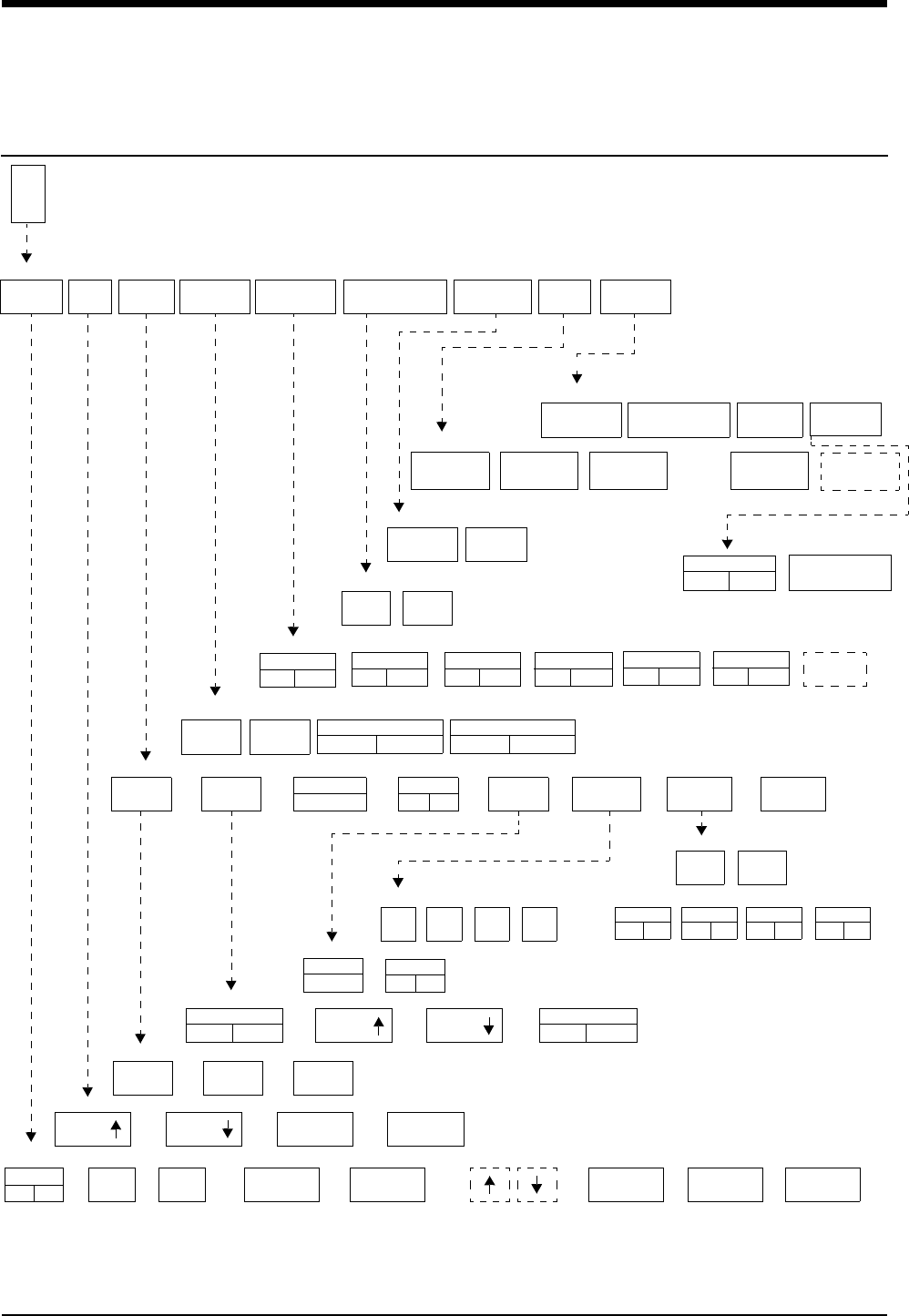
8-1
!
• Based on features purchased, more or fewer keys may appear here than on your menu screens.
ECG Directory
Directory of Keys
E
C
G
2 LEAD
ON OFF
VARITREND
ON OFF
SPLIT VIEW
ON OFF
RATE
SOURCE
SWEEP
SPEED
QRS MONITOR PACED
YES NO CONFIG
TONE EXTENDED
ADULT
INFANT
50
mm/sec
12.5
mm/sec
25
mm/sec
TONE
ON OFF
SPO2 PITCH
ON OFF
VOLUME VOLUME
SIZE SIZE 1 mV 1 mV/cm
CAL
ECG - DISPLAY FORMAT
ECG - SETUP
ECG - CONFIG
ECG - SWEEP SPEED
ECG - SIZE
ECG - QRS TONE
ALARM
LIMITS SIZE SETUP DISPLAY
FORMAT
SUSPEND
PROCESSING RELEARN PRINT
ECG MENU
REVIEW
ALARMS
ON OFF
HI=
130
LO=
40
ABN IN
ROW=5
ABN PER
MIN=OFF
SINGLE
ST = 1.00
MULTI
ST = 0.50
ECG - ALARM LIMITS
1st LEAD
xx
ARR
ON OFF
TRANSFER
DATA
FULL VIEW
ON OFF
ST
LEADS
CASCADE
ON OFF
ECG - LEAD CONTROL
RESTORE
SETTINGS
Select primary heart rate source
ECG ART UA SPO2
Enable alternate rate source(s)
UA
ON OFF
ART
ON OFF
SPO2
ON OFF
ECG
ON OFF
LEAD
CONTROL
NEXT
VIEW
ARR
CLASSES
ST
SEGMENTS
ALL
LEADS
PRINT
ALL
PRINT MENU
AUTO LEAD SWITCH
ON OFF
2nd LEAD
xx
SINGLE LEAD ALARM
ON OFF
CANCEL
PRINT
ST
REVIEW
ARRHYTHMIA
REVIEW
ECG - REVIEW
CLEAR
MEMORY
SAVE
MEMORY
ECG - RELEARN
ECG - SUSPEND PROCESSING
YES NO
RESTORE all user settings within this module
RESP
ON OFF
REPORT
REVIEW
REAL TIME
ST TREND
TREND DISPLAY
ON OFF
TREND TIMEBASE
15 MIN / 30 MIN
YES NO


Contents
ECG
8-3
Overview
When used in conjunction with a Spacelabs Medical Ultraview Care Network
monitor, the ECG function provides a means for continuous monitoring of
electrocardiographic signals. It can detect abnormal cardiac rhythms, including
life-threatening arrhythmias such as asystole, ventricular fibrillation, and
ventricular tachycardia.
The basic ECG software provides alarms for high and low heart rates, ventricular
fibrillation, and asystole.
The Multiview I option provides enhanced arrhythmia detection and alarm
capability. Multiview 1 detects ventricular tachycardia, couplets, and single
abnormal beats in addition to the detection and alarm capabilities of the basic
ECG software.
The Multiview II option expands arrhythmia detection to include pauses and
tachycardias of a supraventricular origin. This option also offers storage
capabilities so that trends of arrhythmia episodes, as well as dominant,
ventricular-paced and AV-paced rhythms, can be reviewed, edited, and printed.
Refer to Arrhythmia on page 9-3 for detailed information about the Multiview
options.
The diagnostic ECG feature, which meets all of the requirements and standards
for electrocardiographic devices, provides the capability to obtain a diagnostic
12-lead report as a function of the monitoring system. The 12-lead report is a set
of diagnostic-quality electrocardiographic waveforms that accurately represent
both the detailed cardiac cycle and the cardiac rhythm.
Overview . . . . . . . . . . . . . . . . . . . . . . . . . . . . . . . . . . . . . . . . . . . . . . . . . . . . . . . 3
ECG Setup. . . . . . . . . . . . . . . . . . . . . . . . . . . . . . . . . . . . . . . . . . . . . . . . . . . . . . 4
Display Detail. . . . . . . . . . . . . . . . . . . . . . . . . . . . . . . . . . . . . . . . . . . . . . . . . . . . 9
Selecting Adult or Neonate Mode . . . . . . . . . . . . . . . . . . . . . . . . . . . . . . . . . . . 11
Monitoring Paced Patients. . . . . . . . . . . . . . . . . . . . . . . . . . . . . . . . . . . . . . . . . 11
Setting and Adjusting Alarms. . . . . . . . . . . . . . . . . . . . . . . . . . . . . . . . . . . . . . . 13
Selecting ECG Leads . . . . . . . . . . . . . . . . . . . . . . . . . . . . . . . . . . . . . . . . . . . . 14
Displaying Additional Waveforms . . . . . . . . . . . . . . . . . . . . . . . . . . . . . . . . . . . 15
Checking the ECG Amplitude . . . . . . . . . . . . . . . . . . . . . . . . . . . . . . . . . . . . . . 15
Adjusting Waveform Size. . . . . . . . . . . . . . . . . . . . . . . . . . . . . . . . . . . . . . . . . . 15
Adjusting Sweep Speed. . . . . . . . . . . . . . . . . . . . . . . . . . . . . . . . . . . . . . . . . . . 16
Adjusting Tones . . . . . . . . . . . . . . . . . . . . . . . . . . . . . . . . . . . . . . . . . . . . . . . . . 16
Changing the Display Resolution. . . . . . . . . . . . . . . . . . . . . . . . . . . . . . . . . . . . 17
Selecting Primary and Alternate Heart Rate Source . . . . . . . . . . . . . . . . . . . . . 17
Suspending/Resuming ECG Processing . . . . . . . . . . . . . . . . . . . . . . . . . . . . . . 18
Printing ECG Recordings. . . . . . . . . . . . . . . . . . . . . . . . . . . . . . . . . . . . . . . . . . 18
Restoring Default Settings . . . . . . . . . . . . . . . . . . . . . . . . . . . . . . . . . . . . . . . . . 19
Power Failure. . . . . . . . . . . . . . . . . . . . . . . . . . . . . . . . . . . . . . . . . . . . . . . . . . . 19
ECG Problem Solving . . . . . . . . . . . . . . . . . . . . . . . . . . . . . . . . . . . . . . . . . . . . 19
ECG Troubleshooting Guide . . . . . . . . . . . . . . . . . . . . . . . . . . . . . . . . . . . . . . . 21
ECG

Ultraview Care Network
8-4
The ECG function:
• detects and displays a waveform representing each cardiac cycle
• determines lead configuration options
• displays heart rate (heart rate is computed from an average of eight beats
with a provision for immediately updating the heart rate should the rate slow
suddenly)
• detects pacemaker pulses
• initiates ECG-related alarms when limits are violated
• acquires, displays, and prints diagnostic-quality 12-lead reports
ECG traces for multiple leads can be displayed, however, ECG monitoring is
always performed on two leads. Lead faults are identified by a message on the
screen. If automatic lead switching is enabled, the system automatically switches
to another appropriate lead to continue monitoring in the event of a lead fault.
ECG Setup
The ECG waveform area displays the CHECK SETUP key and sounds an alarm
when the monitor is powered ON, following a monitor reset, and after an ECG
module is inserted. Touch the ECG key to dismiss the CHECK SETUP key and
silence the alarm. Verify that the system configuration (for example, alarm limits,
lead selection, etc.) is appropriate before you begin, or resume, monitoring.
WARNING:
• Following a lead switch and until the patient’s rate and
morphology are learned, some ECG alarms are not active.
Alarms for ventricular fibrillation and asystole continue to
be active. However, ECG alarms for high rate, low rate, run,
couplet, abnormal per minute, and tachycardia are not.
!
• Monitor input circuits are protected for electrosurgical
equipment and defibrillator use.
• Cardiac pacemakers or other electrical stimulators do not affect
and are not affected by operation of this unit.
• You can define your own default settings for such
characteristics as alarm limits and display configuration. Refer
to Module Configuration Manager on page 7-5 for further
information.
!
• When the Check Setup feature is disabled, the CHECK SETUP
key will not display and its associated alarm tone will not sound.
Contact your system administrator to enable this feature.
WARNING:
• Signals resulting from devices such as Automatic
Implantable Cardiac Defibrillators (AICD) may momentarily
blank the ECG trace rather than display an out-of-range
signal. In such cases, it may not be apparent that the AICD
has fired and the condition of the patient should be
checked. In all instances of AICD firing, the monitor will
redisplay the ECG waveform within 5-seconds.

ECG
8-5
Accessories
Use silver/silver-chloride electrodes or their equivalent, and always connect all
electrodes required for a particular lead. Missing electrodes may result in the loss
of ECG tracing.
WARNING:
• Use only monitoring cables and safety lead wires to protect
against accidental connection to electrical power cords or
outlets. Failure to do so may result in adverse health
consequences or death.
!
• Use only Spacelabs Medical recommended electrodes. Some
electrodes may polarize, creating large offset potentials which
can compromise recovery time after application of defibrillator
pulses. Squeeze bulb electrodes, commonly used for diagnostic
ECG recording, may be particularly vulnerable to this effect.
CAUTION:
• Visually inspect each lead wire for obvious damage and
replace them as needed.
• When placing a telemetry transmitter on the patient, make
sure the front of the transmitter is always facing away from
the patient.
• Use only patient cables and lead wires specified by
Spacelabs Medical. Other cables and lead wires may
degrade performance and may damage the monitor during
defibrillation or high frequency electrosurgery. Non-
Spacelabs Medical cables and lead wires may also change
the required input impedance and DC offset voltage,
affecting monitor performance.
• Do not use stainless steel electrodes.
• Place the electrodes as far away from the electrosurgery
site as possible because considerable high frequency
current may flow into the electrodes. This can cause
patient burns, especially if a defect is present in the neutral
cable of the electrosurgical unit. Placing electrodes too
close to the electrosurgery site can also cause a noisy ECG
trace.
• Do not allow conductive parts of electrode leads or
connectors, including the neutral electrode, to contact
other conductive parts, including the ground.
• Poor cable dress or improper electrode preparation may
cause line isolation monitor transients to resemble actual
cardiac waveforms and thus inhibit heart rate alarms. Refer
to Patient Preparation and Electrode Application on page 8-
6 for details on proper electrode preparation and
application.

Ultraview Care Network
8-6
Patient Preparation and Electrode Application
To set up for ECG monitoring, first attach lead wires to the patient cable or
telemetry transmitter. Match the color-coding on the patient cable or telemetry
transmitter to the lead wire color.
Next, attach each electrode to its lead wire before applying the electrodes to the
patient. Figure 8-1 displays the correct procedure for applying electrodes to a
patient. Be sure to press firmly around the entire edge of the adhesive surface. Do
not apply pressure over the gel column itself as this may trap air or displace the
conductive gel, which may degrade the signal significantly. Gel displacement
arising from attaching the electrode to the lead wire after applying the electrode to
the patient may also degrade the signal.
Electrodes should be placed over flat, non-muscular areas of the body to minimize
muscle artifact (refer to Figure 8-2 and Figure 8-3). This is particularly important
for telemetry patients who are commonly ambulatory. If necessary, after the
electrodes and lead wires have been attached, tape a stress loop (a loop of lead
wire close to the electrode that minimizes stress or pulling on the electrode itself.
Stress-looping significantly improves ECG signal quality, particularly for
ambulatory patients.
ECG monitoring begins when the module detects a signal via connection of an
ECG patient cable to the module or by installation of a battery in a telemetry
transmitter.
ECG monitoring requires the following minimum conditions:
• ECG electrodes must be properly attached the patient and lead wires must
be properly attached to the patient cable or telemetry transmitter.
• The patient cable must be connected to the module or telemetry transmitter.
• The module must be connected to a monitor that is powered ON.
Telemetry ECG monitoring requires the following additional minimum conditions:
• The telemetry transmitter must have a functional battery.
• The telemetry receiver module must be tuned to the telemetry transmitter’s
frequency (channel number).
• The telemetry receiver module must be connected to a Spacelabs Medical
diversity antenna.
• Refer to Assigning a Telemetry Channel on page 17-14 for more information.
Figure 8-1: Electrode application
1. Attach electrode to lead wire. 2. Apply electrode to skin.
To prepare the patient:
1Wash area with soap and water.
2If necessary, shave the area
where you plan to position the
electrodes.
3Clean the skin with alcohol.
4Dry the skin thoroughly.
5Abrade the skin.
To apply ECG electrodes:
1Attach electrode to lead wire.
2Apply electrode to patient skin.
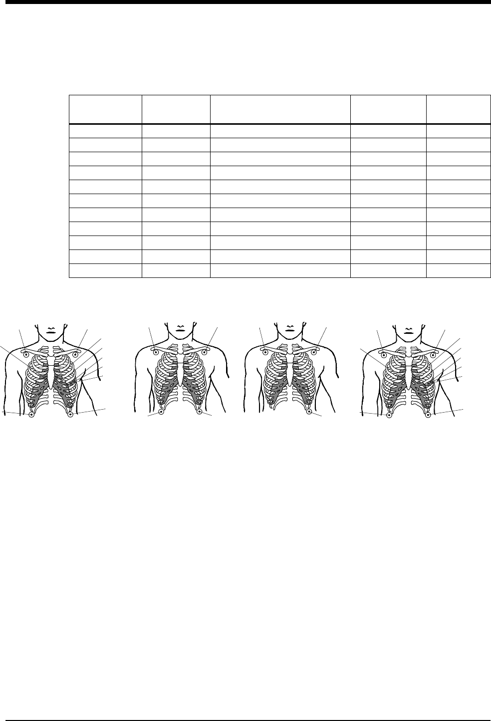
ECG
8-7
Table 1 lists electrode color and identifier codes.
Figure 8-2: Adult electrode placement
Table 1: Electrode Color and Identifier Codes
AHA Electrode
Identifier
AHA Color
Code Electrode Placement IEC Electrode
Identifier
IEC Color
Code
RA White Right Arm R Red
LA Black Left Arm L Yellow
LL Red Left Leg F Green
RL Green Right Leg N Black
V1 Brown/Red 4th Intercostal - Right Sternum C1 White/Red
V2 Brown/Yellow 4th Intercostal - Left Sternum C2 White/Yellow
V3 Brown/Green Midway Between V2 and V4 C3 White/Green
V4 Brown/Blue 5th Intercostal - Left Midclavicular C4 White/Brown
V5 Brown/Orange Left Anterior Axillary Line at V4 C5 White/Black
V6 Brown/Violet Left Midaxillary Line at V4 C6 White/Violet
C Brown Chest C White
LARA
LL
RL
LARA
LL
Chest electrodes must be
appropriately relocated on
patient’s chest to view alternate
precordial leads.
Chest electrodes
must be appropriately
placed on the patient’s
chest to view precordial
leads.
5 Electrodes
I, II, III, aVR, aVL, aVF,
V1 - V6
4 Electrodes
I, II, III, aVR, aVL, aVF
3 Electrodes
I, II, III
10 Electrodes
LARA
V1 (C1)
LL
RL
LARA
V1 (C1)
LL
RL
V6 (C6)
V2 (C2)
V3 (C3)
V4 (C4)
V5 (C5)
V6 (C6)
V2 (C2)
V3 (C3)
V4 (C4)
V5 (C5)
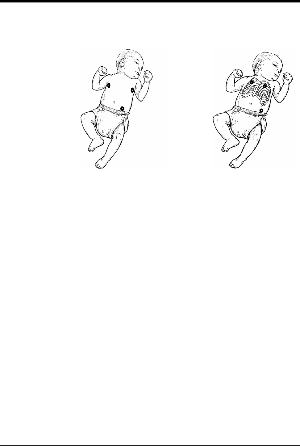
Ultraview Care Network
8-8
Figure 8-3: Neonate electrode placement
LA
RA
LL
Alternate Method:
Position RA and LA electrodes at
the 2nd intercostal space,
midclavicular line. Position LL
below the diaphragm, preferably
below the umbilicus.
RA LA
LL
Maximum Impedance Change:
Position RA and LA electrodes at
the nipple level, midaxillary line.
Position LL below the diaphragm,
preferably below the umbilicus.
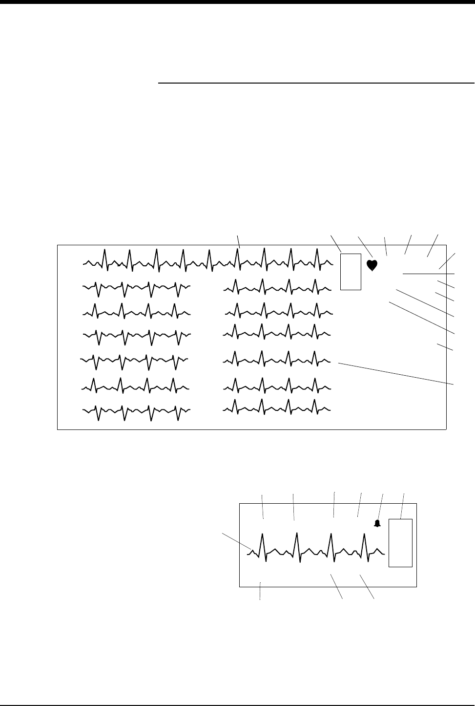
ECG
8-9
Display Detail
Your ECG display may differ from the one shown here depending on: 1) the type
of monitor you are using, 2) the options in your module, 3) which functions you
have enabled, and 4) which patient type you have selected.
The illustrations below show the displays with arrhythmia and ST analysis ON.
Figure 8-4: Bedside monitor display (full view)
Figure 8-5: Central monitor display (split screen)
!
• For telemetry display information refer to Display Detail on page
17-12.
*
*
E
C
G
II
A=3
A/M 10
ROW 4
120
40
70
AVR
AVL
AVF
V4
V5
V6
V1
V2
V3
III
II
I
I
II
III
V1
V2
V3
AVR
AVL
AVF
V4
V5
V6
0.16
0.00
1.44
-1.44
2.88
1.44
0.16
0.16
-0.16
-0.16
-0.16
0.24
ST=0.00***
MON PACED
쐅
쐉
쐈
씏
씎
씈
E
C
G
HR=70 SPO2=99% 123/90 25/12
BED 01 DANIELS,R
RR=23 NIBP=155/100
씌씍
쐈씊씉씋씈
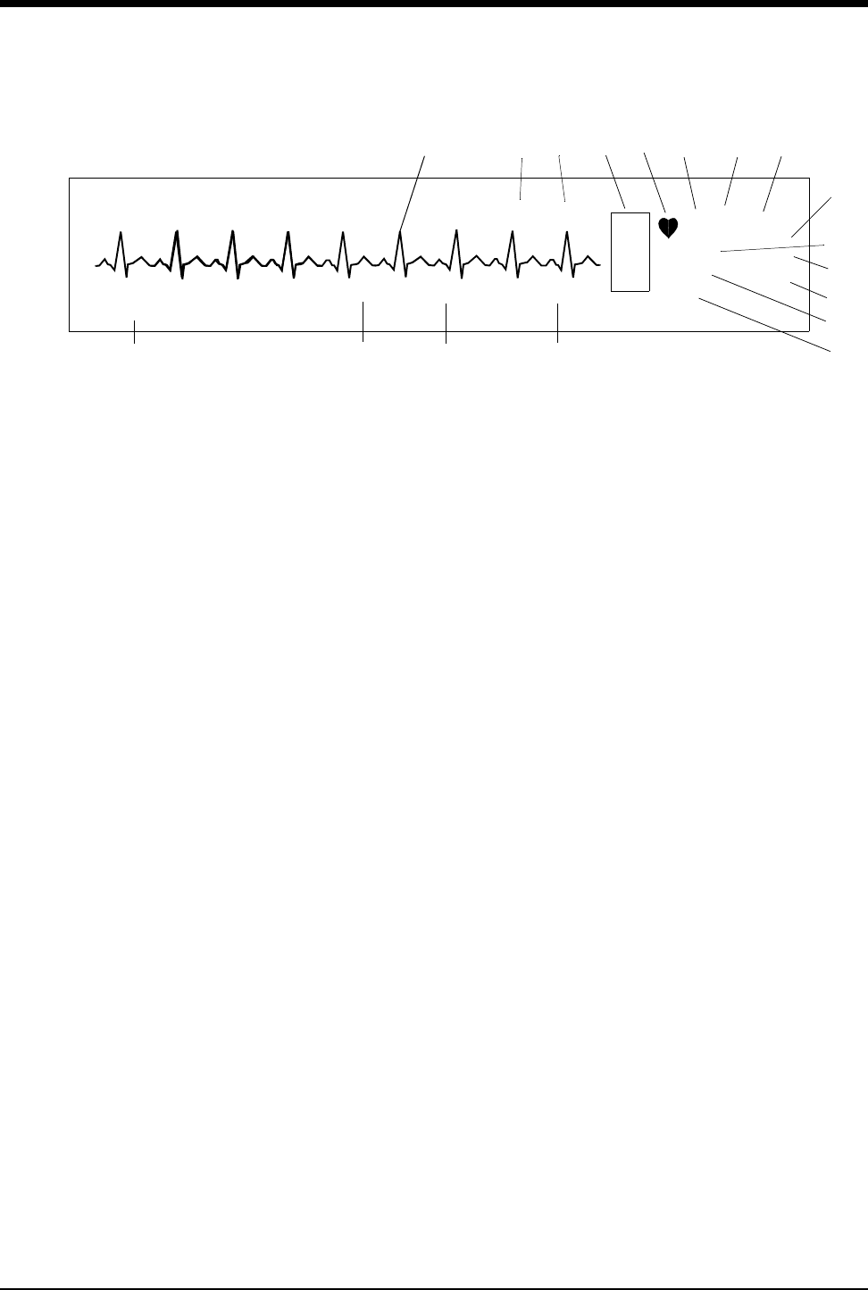
Ultraview Care Network
8-10
Figure 8-6: Central monitor display
ECG trace for first lead
Bed name
ECG key for first lead
QRS indicator (flashes once per detected beat)
ECG lead designator
Display resolution (monitor or extended)
Paced operation indication (pacemaker detection is enabled)
Abnormals per minute alarm limit *
ST segment level for first lead**
(the asterisk indicates ST alarms are enabled)
쐅Abnormals in a row alarm limit *
쐈ECG rate alarm limits. Split-screen central monitors display a bell symbol
when alarms are enabled; bedside monitors display the rate alarm limits
(120/40)
쐉Abnormals per minute counter *
씈Current heart rate
씉Arterial pressure
씊Pulmonary artery pressure
씋SpO2 level
씌Respiration rate
씍Non-invasive blood pressure (systolic/diastolic)
씎ECG Full View display
씏ST Segment levels for Full View Display
* Only appears with the Multiview I or II option in the adult mode with Arrhythmia
detection enabled.
** Only appears in adult mode with the ST segment analysis option.
E
C
G
II MON PACED
ST=0.00
A=3
A/M 10
ROW 4
120
40
70
123/90 25/12
***
*
*
BED 01 DANIELS,R
RR=23 NIBP=155/100 SPO2=99%
씌씍 씋 씈
쐉
쐈
쐅
*
씊씉

ECG
8-11
Selecting Adult or Neonate Mode
The ECG function provides both adult and neonate operational modes. When you
select adult or infant, ECG alarm limits are adjusted based on your selection.
Monitoring Paced Patients
When you monitor pacemaker patients, use the Paced feature to automatically
enhance pacemaker spikes for display and eliminate them from the heart rate
counter.
To prevent pacemaker pulses from being counted as actual beats, specialized
circuitry removes the pacemaker pulses from the ECG signal and replaces them
with pacemaker flags.
If the interval between the pacemaker pulse and the QRS complex is greater than
150 milliseconds, the beat is considered to have originated in the atria, and is not
classified as a paced beat.
!
• If the enhanced vital sign display feature is enabled, you can
view SpO2, respiration rate, and non-invasive pressure in the
ECG zone on central or remote bedside monitors. However, no
alarms are active.
WARNING:
• When the system is in the neonate mode, ECG and
respiration alarm activation can be delayed from 0- to
3-minutes. The factory default setting for alarm delay is
3-minutes. Closely observe the patient during this period.
!
• The optimal leads for monitoring paced patients may vary. To
select an optimal trace, sequence through the available leads. If
pacemaker spikes are not detected or if the heart rate is
incorrectly counted, select another lead or change electrode
position.
• In telemetry monitoring, pacemaker spikes are detected on
lead II.
To specify the patient type:
1Touch ECG.
2Touch SETUP.
3Touch CONFIG.
4Select ADULT or INFANT.
To monitor paced patients:
1Touch ECG.
2Touch SETUP.
3Select PACED YES.

Ultraview Care Network
8-12
When using temporary transvenous pacemakers, you may want to check the
pacemaker capture threshold on a regular basis (refer to your hospital protocol for
frequency and procedure). Since the pacemaker flag substituted by the monitor
does not represent the true amplitude of the detected pacemaker pulse, you will
need to temporarily deactivate the Ultraview Care Network pacemaker software to
check the capture threshold. In addition, placing the display in the extended mode
and changing the sweep speed to 50 mm/sec will enhance the resolution and
improve visualization of the pacemaker pulse amplitude. Remember to return to
the monitor mode, reactivate pacemaker detection, and reset desired sweep
speed after checking the capture threshold.
Permanent transvenous pacemakers employing a bipolar lead system are
capable of obtaining capture of the cardiac muscle at a much lower current than
those with unipolar lead systems. For optimal paced rhythm detection, the
pacemaker pulse and QRS complex must be of sufficient voltage. To determine if
the monitor is correctly detecting the pacemaker pulses, verify that the Paced
mode is activated. Each paced beat should have a pacemaker flag superimposed
on the ECG trace at the appropriate point prior to the QRS complex. If flags are
not consistently observed, sequence through the available leads for a better lead,
or reposition electrodes, to optimize pacemaker detection. Check the amplitude of
the QRS complex by inserting a 1 mV calibration pulse in the ECG trace as
described in Checking the ECG Amplitude on page 8-15.
WARNING:
• ECG detection circuitry may continue to count the
pacemaker rate during occurrences of cardiac arrest or
some arrhythmias. Do not rely entirely upon ECG rate
alarms. Keep pacemaker patients under close surveillance.
• During electrosurgical activity, the system may not
accurately detect paced beats due to the electrical
interference.
• The system may insert pacemaker flags into the ECG
signal in response to signals that are not pacemaker
pulses. Therefore, if you use a Spacelabs Medical monitor
to observe pacemaker performance, you must take into
account all possible sources of pacemaker flags.
• Use the pacemaker manufacturer's performance analyzer
as the primary means of evaluating pacemaker operation.
• Operation of some pacemaker programs may suppress the
ECG waveform, preventing QRS detection and rate
counting. This may result in an erroneous asystole alarm.
• Signals resulting from devices such as Automatic
Implantable Cardiac Defibrillators (AICD) may momentarily
blank the ECG trace rather than display an out-of-range
signal. In such cases, it may not be apparent that the AICD
has signaled and the condition of the patient should be
checked. In all instances of AICD signaling, the bedside or
central will redisplay the ECG waveform within 5-seconds.
To check capture threshold:
1Touch ECG.
2Touch SETUP.
3Select PACED NO.
4Select EXTENDED.
5Touch SWEEP SPEED.
6Select 50 mm/sec.
7Perform capture threshold
verification procedure
according to your protocol.
8Touch ECG.
9Touch SETUP.
10 Select PACED YES.
11 Select MONITOR.
12 Touch SWEEP SPEED.
13 Select desired speed.

ECG
8-13
Setting and Adjusting Alarms
ECG alarms default to the ON position when the module is inserted into a monitor
that is powered ON. Events that can cause an ECG alarm include:
• High or low rate
• Ventricular fibrillation (VFIB)
• Asystole
Additional conditions which can cause an alarm with the Multiview I or II options
include:
• Abnormals in a row (couplets or runs)
• Abnormals per minute
• Tachycardia (of supraventricular origin)
Refer to Arrhythmia on page 9-3 for details concerning arrhythmia alarms or to ST
Analysis on page 10-3 for details concerning ST alarms.
Initial Alarm Limits for Heart Rate
At the completion of a learn sequence (refer to Learning the Dominant Waveform
on page 9-4), the rate alarm limits are initialized using fixed or learned criteria.
When you change the adult/neonate configuration, the system changes the alarm
limits accordingly. You can adjust these limits up or down as needed.
WARNING:
• If ECG monitoring is interrupted and subsequently resumed
during an asystole event, 5- to 6-seconds will elapse prior
to the monitor sounding and displaying the Asystole alarm.
• If ECG monitoring is initiated during an asystole event, 10-
to 11-seconds will elapse prior to the monitor sounding and
displaying an Asystole alarm.
!
• If the alarm limit for high rate, low rate, abnormals per minute
(A/M) or abnormals in a row (ROW) is displayed in reverse
video, this is an indication that alarm tone, alarm recording, and
alarm watch have been disabled for the indicated alarm.
To set or adjust rate alarms:
1Touch ECG.
2Touch ALARM LIMITS.
3Touch ALARMS ON.
4Touch HI = or LO = key.
5Use arrow keys to adjust.

Ultraview Care Network
8-14
Alarms
Table 2 displays the conditions for which an alarm may be initiated.
Selecting ECG Leads
When you select a precordial lead, a help message appears that describes the
proper location for the chest electrode. For example, if you select V1, the
message (C) 4TH INTERCOSTAL SPACE, RIGHT STERNAL BORDER is
displayed.
No message appears when you choose to display a limb or augmented lead (for
example, I, II, III, AVR, AVL, or AVF).
When you change lead selections, the new waveform is displayed and the learn
sequence is automatically initiated. If you change lead selections while processing
is suspended, the module initiates the learn sequence when you resume
processing.
Table 2: ECG Alarms
Alarm Cause Of Alarm Display Indication
VFIB Ventricular fibrillation detected VFIB
Asystole >5-seconds with no QRS detected Heart rate 0; flashing low rate limit;
ASYSTOLE
High Heart Rate High limit violated Flashing high limit and
HI RATE ALARM
Low Heart Rate Low limit violated Flashing low limit and
LO RATE ALARM
Chan 1 & 2 - Leads Off One or more of the electrodes for
both ECG leads are off or loose
No ECG trace and
CHAN 1 & 2 LEADS OFF
Chan 1 - Lead Off One or more of the electrodes for the
first ECG lead are off or loose
No ECG trace and
CHAN 1 - LEADS OFF
Chan 2 - Lead Off One or more of the electrodes for the
second ECG lead are off or loose
No ECG trace and
CHAN 2 - LEADS OFF
Rate Source Unavailable Heart rate is not available from either
the primary or any alternate heart
rate source
HR UNAVAILABLE
Noisy Signal Excessive noise, artifact or baseline
shift
NOISY SIGNAL
Low ECG Voltage QRS amplitude is between 0.16 and
0.20 mV (adult only)
ECG VOLTAGE TOO LOW
!
• Changing your selection for the first lead may change the
selection for the second lead.
To change the lead selection:
1Touch ECG.
2Touch LEAD CONTROL.
3Touch 1ST LEAD or 2ND
LEAD.
4Select lead.

ECG
8-15
Displaying Additional Waveforms
Multiple ECG traces can be displayed by selecting either FULL VIEW, SPLIT
VIEW, 2ND LEAD or CASCADE.
A second waveform zone can be used to display either a second ECG lead or a
cascaded trace from the first ECG zone. However, you cannot display both a
second ECG trace and a cascaded ECG trace at the same time.
Data in a cascaded ECG trace wraps from the first waveform zone into the second
to display 12-seconds of data for the selected lead. While the cascaded trace is
displayed, the text in the parameter key for the second zone displays STOP.
Touching the STOP key freezes the trace for viewing. While the display is frozen,
the text in the key displays START. Touching the key again unfreezes the trace.
Checking the ECG Amplitude
Touching the 1 mV CAL key inserts a 1 mV amplitude calibration pulse into all
ECG tracings. Use this calibration pulse as a reference to determine whether the
amplitude of the ECG waveform exceeds the minimum voltage threshold.
For ECG detection, the QRS amplitude must be at least 0.2 - 0.5 mV in an adult
and 0.15 - 0.5 mV in a neonate.
Adjusting Waveform Size
You can increase or decrease the display size of the ECG waveform. This
changes the displayed size only and does not affect the signal gain.
When you touch the 1 mV/cm key, you set the ECG waveform size to 1 millivolt
per centimeter. This standardizes the waveform to aid in accurately viewing QRS
complexes for ST segment deviation. The factory default setting for ECG
waveform size is 0.5 mV/cm.
WARNING:
• Following a lead switch and until the patient’s rate and
morphology are learned, some ECG alarms are not active.
Alarms for ventricular fibrillation and asystole continue to
be active; however, some ECG alarms (high rate, low rate,
run, couplet, abnormal per minute, and tachycardia) are
not.
!
• When displaying multiple ECG leads in the split-view or full-
view format, the waveform size of all leads is adjusted
simultaneously.
To display six traces (requires a
12-lead cable):
1Touch ECG.
2Touch DISPLAY FORMAT.
3Select SPLIT VIEW ON.
To display twelve traces (requires
a 12-lead cable):
1Touch ECG.
2Touch DISPLAY FORMAT.
3Select FULL VIEW ON.
To check the ECG amplitude:
1Touch ECG.
2Touch SIZE.
3Touch 1 mV CAL.
To adjust waveform size:
1Touch ECG.
2Touch SIZE.
3a Touch the arrow keys to adjust.
-OR-
3b Touch the 1mV/cm key to
standardize.

Ultraview Care Network
8-16
Adjusting Sweep Speed
The sweep speed determines the speed at which the ECG traces move across
the screen. When multiple ECG traces are displayed, changes to SWEEP SPEED
affect all waveform traces. Available sweep speeds are 12.5, 25, or
50 mm/second. The factory default setting is 25 mm/second.
Adjusting Tones
The QRS tone is the sound the monitor generates with each detected R wave.
When you enable the QRS tone, you can adjust the volume and select whether to
modulate the tone with the current SpO2 value. The factory default setting for
QRS tone is OFF.
The factory default setting for SpO2 pitch is OFF. In this setting, the monitor uses
the default pitch for the QRS tone. When you enable the SpO2 pitch tone, the
monitor modulates the pitch of the QRS tone higher or lower depending on the
current SpO2 value. When you disable the QRS tone, the system automatically
turns SpO2 pitch modulation OFF.
!
• Changing the ECG sweep speed may also change the speed of
the invasive pressure waveforms. Refer to Pressure on page
18-3 for more details.
To adjust the sweep speed:
1Touch ECG.
2Touch SETUP.
3Touch SWEEP SPEED.
4Select the desired sweep speed.
To set the QRS tone:
1Touch ECG.
2Touch SETUP.
3Touch QRS TONE.
4Select TONE ON.
5Use arrow keys to adjust
volume.
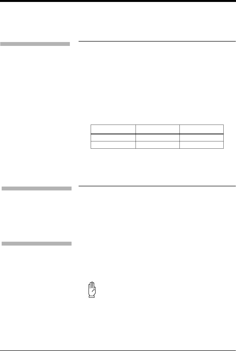
ECG
8-17
Changing the Display Resolution
The MONITOR/EXTENDED key determines the display resolution of the ECG
traces.
• The Monitor mode displays a reduced frequency range, but filters out more
noise for better viewing.
• The Extended mode displays a broader frequency range, and also more
noise.
The factory default setting for display resolution is monitor mode.
Selecting Primary and Alternate Heart
Rate Source
You may select a primary rate source as well as enable alternate rate sources.
Rate sources include ECG, ART (arterial pressure), UA (umbilical artery) and
SpO2. If you enable one or more alternate sources, a heart rate will be displayed,
if available, from either the primary or an alternate source. If you do not enable
any alternate sources, a heart rate will only be displayed if the primary rate source
is available.
If a heart rate is not available from any source, the message HR UNAVAILABLE is
displayed in the ECG waveform zone, and ??? replace the rate numbers.
!
• Changing the display resolution does not change the waveform
bandwidth used to analyze the ECG signals for arrhythmia and
ST segment level.
Table 3: Display Resolution
Key Telemetry Non-telemetry
MONITOR 0.5 — 30 Hz 0.5 — 40 Hz
EXTENDED 0.05 — 30 Hz 0.05 — 150 Hz
!
• If ART is to be used as an alternate heart rate source,
Spacelabs Medical recommends setting up each monitor with
only one arterial pressure channel.
•Use of SpO
2 as the primary heart rate source is not
recommended by Spacelabs Medical.
CAUTION:
• Cardiovascular Artifact (CVA) detection is disabled for the
respiration channel when using an alternate heart rate
source.
To change the display resolution:
1Touch ECG.
2Touch SETUP.
3Select MONITOR or
EXTENDED.
To select a primary heart rate
source:
1Touch ECG.
2Touch SETUP.
3Touch RATE SOURCE.
4Select the desired primary rate
source (ECG, ART, UA, or
SPO2).
To enable alternate rate sources:
1Touch ECG.
2Touch SETUP.
3Touch RATE SOURCE.
4Set the desired alternate
source(s) to ON (ECG, ART,
UA, and/or SPO2).

Ultraview Care Network
8-18
Suspending/Resuming ECG Processing
When you touch YES in the Suspend Processing menu, ECG and respiration
waveforms continue to be displayed, but no processing occurs. If you touch NO,
the display returns to the ECG menu without affecting ECG and respiration
processing.
When you suspend ECG processing:
• the message ECG PROCESSING SUSPENDED appears in the ECG
waveform zone. In modules with the respiration option RESP PROCESSING
SUSPENDED appears in the respiration waveform zone.
• question marks replace the heart rate immediately and replace the ST
segment value after 30-seconds. If an alternate heart rate source is available,
the new heart rate is displayed. Question marks (???) will continue to display
for the ST segment value.
• the message ECG ALM OFF replaces the alarm limits (if no alternate rate
source is available).
• the keys in the ECG Alarm Limits menu display dotted outlines to indicate
they are disabled (if no alternate rate source is available).
• the key SUSPEND PROCESSING changes to RESUME PROCESSING.
Printing ECG Recordings
All printouts of ECG data are annotated with the following:
• Bed identification
• Time and date of the printout
• Lead designator
Depending on the printer model and software version, the ALL LEADS recording
can be printed on a single page or as consecutive two- or four-channel recordings.
For these recording formats, 6.25-seconds of waveform data will be printed for all
available leads.
If you are using a 90838 PrintMaster and if all the leads are connected, touching
the STAT REPORT key will provide a 12-lead report. For this recording format,
2.5-seconds of waveform data will be printed for each lead plus 10-seconds of
waveform data for a rhythm lead.
A 12-lead report can be scheduled to print at regular time intervals using the
AUTO REPORT and AUTO PRINT features. Available intervals are 30-minutes,
1-hour, 2-hours, 4-hours, 8-hours, and 24-hours.
!
•A printer (with 1.10.04 version software or greater) is required
for the STAT REPORT feature.
•A 12-lead report cannot be printed using the 90449 printer
module.
To suspend ECG processing:
1Touch ECG.
2Touch SUSPEND
PROCESSING.
3Touch YES.
To resume ECG processing:
1Touch ECG.
2Touch RESUME
PROCESSING.
3Touch YES.
To print recordings of all leads:
1Touch ECG.
2Touch PRINT.
3Touch ALL LEADS.
To print a 12-lead report:
1Touch ECG.
2Touch REVIEW.
3Touch REPORT REVIEW.
4Touch STAT REPORT.
5Touch PRINT.
To print a 12-lead report at
pre-selected intervals:
1Touch ECG.
2Touch REVIEW.
3Touch REPORT REVIEW.
4Select AUTO REPORT of
30-minutes, 1-hour, 2-hours,
4-hours, 8-hours, or 24-hours.
5Touch AUTO PRINT ON.

ECG
8-19
Restoring Default Settings
Using the Module Configuration Manager feature, you can restore all default
settings. User-configurable settings are described in Setting User-Defined Default
Values on page 7-7.
After the default settings are restored, the system initiates a learn sequence.
Following the learn sequence, rate and ST alarm limits are reset.
Power Failure
In the case of a power failure, the remote module housing (90499) provides +5V
of power to maintain data integrity. If the power is interrupted to the remote
module housing but not to the monitor, the following will occur:
• all parameters will display ??? in the numeric zone
• ECG will display Channel 1 & 2 Leads Off
• Respiration will display Loss of Signal
• Cardiac output will display Catheter Fault and Probe Fail
•SpO
2 will display Adapter Disconnected
ECG Problem Solving
In general, if ECG signal quality is poor (as evidenced by wandering baseline,
excessive noise, or muscle or respiration artifact), try the following solutions:
• Ensure that the patient's skin was properly prepared.
• Ensure that all electrodes are firmly attached and in good condition.
• Ensure that the electrodes are positioned on a flat, non-muscular area.
• Ensure that lead wires are properly fastened and in good condition.
If this fails to resolve the problem, select a different lead.
By following the instructions provided in this chapter and discussed during
inservice education, you can avoid most common monitoring problems. If a
problem occurs, consult the ECG Troubleshooting Guide on page 8-21. The
following additional information should help you resolve a few of the more
complex problems.
Lead Fault Indication
If a lead fault occurs, the message CHECK XX is displayed in the ECG waveform
zone, where XX identifies the failed or missing electrode. If automatic lead
switching is enabled, the module selects another lead automatically so that
monitoring is uninterrupted. If automatic lead switching is disabled, a LEAD OFF
message is displayed.
!
• RESTORE SETTINGS changes the user-configurable settings
for all parameters in the module.
To restore default settings:
1Touch ECG.
2Touch SETUP.
3Touch RESTORE SETTINGS.
4Select YES.

Ultraview Care Network
8-20
Noise Detection
Upon detection of noise, a NOISY SIGNAL message is displayed in the ECG
waveform zone. If both the 1st and 2nd leads are noisy, the module suspends
processing temporarily. If the noise persists for 10-seconds, the system sounds a
tone. When the noise disappears, the message and tone cease.
False Alarms
Careful attention to skin preparation and electrode application, especially during
setup, will reduce false alarms. Should false alarms occur, check for the following:
• There may be excessive noise on the signal (the most common cause of
false alarms). Electrodes misplaced over muscles or a poor lead connection
can cause significant noise when the patient moves.
• Heart rate limits may be set too close to patient's heart rate. Check to see if
this is the case and adjust the limits as necessary.
• The ECG amplitude may have dropped below the R-wave detector threshold
level causing false low rate alarms. Reposition the electrodes to obtain a
QRS amplitude of at least 0.20 mV (adult) and 0.15 mV (neonate).
• QRS frequency components and shape may be unsatisfactory for accurate
beat detection and classification. Make necessary changes in electrodes,
electrode sites or lead selection to restore a good signal.
• In some cases, VFIB may resemble previously classified abnormal beats
which may cause VFIB to be detected as a RUN. If this occurs, use the
waveform display as the primary indication of condition.
• The module may not recognize some beats as morphologically different from
the learned dominant beat. You may be able to improve performance by
changing electrode positions or switching to a lead setting that provides
better differentiation between the dominant and abnormal beats.
!
• If monitoring is interrupted due to overload or saturation of the
input amplifiers, including overload caused by a defibrillator
discharge, the ECG trace is displayed as an out-of-range signal
accompanied by a NOISY SIGNAL or an HR UNAVAILABLE
message, or both. If the overload or saturation condition
persists, the ECG trace is displayed as a flat line signal
accompanied by an ASYSTOLE message.
• If the displayed waveform does not appear noisy, but the
NOISY SIGNAL message persists, check all leads for noise
before calling a qualified service person.

8-21
ECG Troubleshooting Guide
Clinical Situation Possible Cause Solution
AC noise ■Display resolution set to extended mode
(0.05 to 150 Hz).
■Select monitor mode (0.5 - 40 Hz).
■Electrodes dry. ■Repeat skin preparation and apply new
moist electrodes.
■Patient cable entwined with other
electrical devices.
■Separate patient cable from all other cables.
Baseline wanders ■Patient moving excessively. ■Use stress loops to secure lead wires and
cable to the patient.
■Respiration artifact. ■Select another lead or reposition the
electrodes.
■Electrodes dry. ■Repeat skin preparation and apply new
moist electrodes.
Low amplitude ECG ■Skin improperly prepared. ■Abrade skin and reapply electrodes.
■Lead selected not showing QRS
complex with greatest amplitude.
■Check 12-lead ECG to determine better
monitoring lead and reposition electrodes.
■Electrodes could be positioned too near
bone or muscle mass.
■Select another lead or reposition electrodes.
Module won’t learn ■ECG signal too noisy for initialization. ■Improve signal quality by repeating skin
preparation and/or repositioning electrodes.
■ECG voltage below threshold. ECG
VOLTAGE TOO LOW message may be
displayed.
■Perform the following steps as needed.
1. Check cables, lead wires and
electrodes, then relearn patient rhythm.
2. Change lead or reposition electrodes.
No ECG trace ■Improper attachment of ECG connector
cable to the module/or leads off.
■Remove, then re-plug the connector into the
module or reconnect the leads.
■LEDs flashing on front panel of module. ■Call a qualified service person.
■Module is not seated into the monitor or
remote housing.
■Remove, then reinsert the module or
exchange the module.
Excessive alarms ■Electrodes dry. ■Repeat skin preparation and apply new
moist electrodes.
■Alarm limits set too close to patient’s
normal heart rate.
■Readjust alarm limit.
■Excessive interference: patient cable or
wires routed too close to other electrical
devices.
■Reroute cables and leads.
■Excessive patient movement or muscle
tremor.
■Reposition electrodes and use stress loops
to secure lead wires and cable to the
patient.
