Spectralux 13281-1 VHF Data Link Device User Manual 426812
Spectralux Corporation VHF Data Link Device 426812
UserManual.wiki
>
Spectralux
>
13281 1 User Manual
Users Manual
Navigation menu
Upload a User Manual
Namespaces
Wiki Guide
HTML
PDF
Info
Views
User Manual
Discussion / Help
Navigation


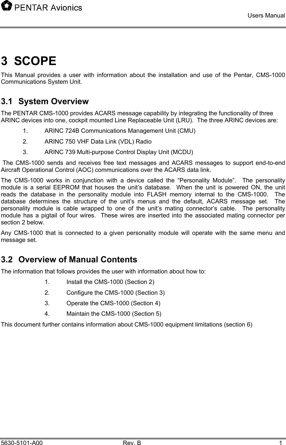
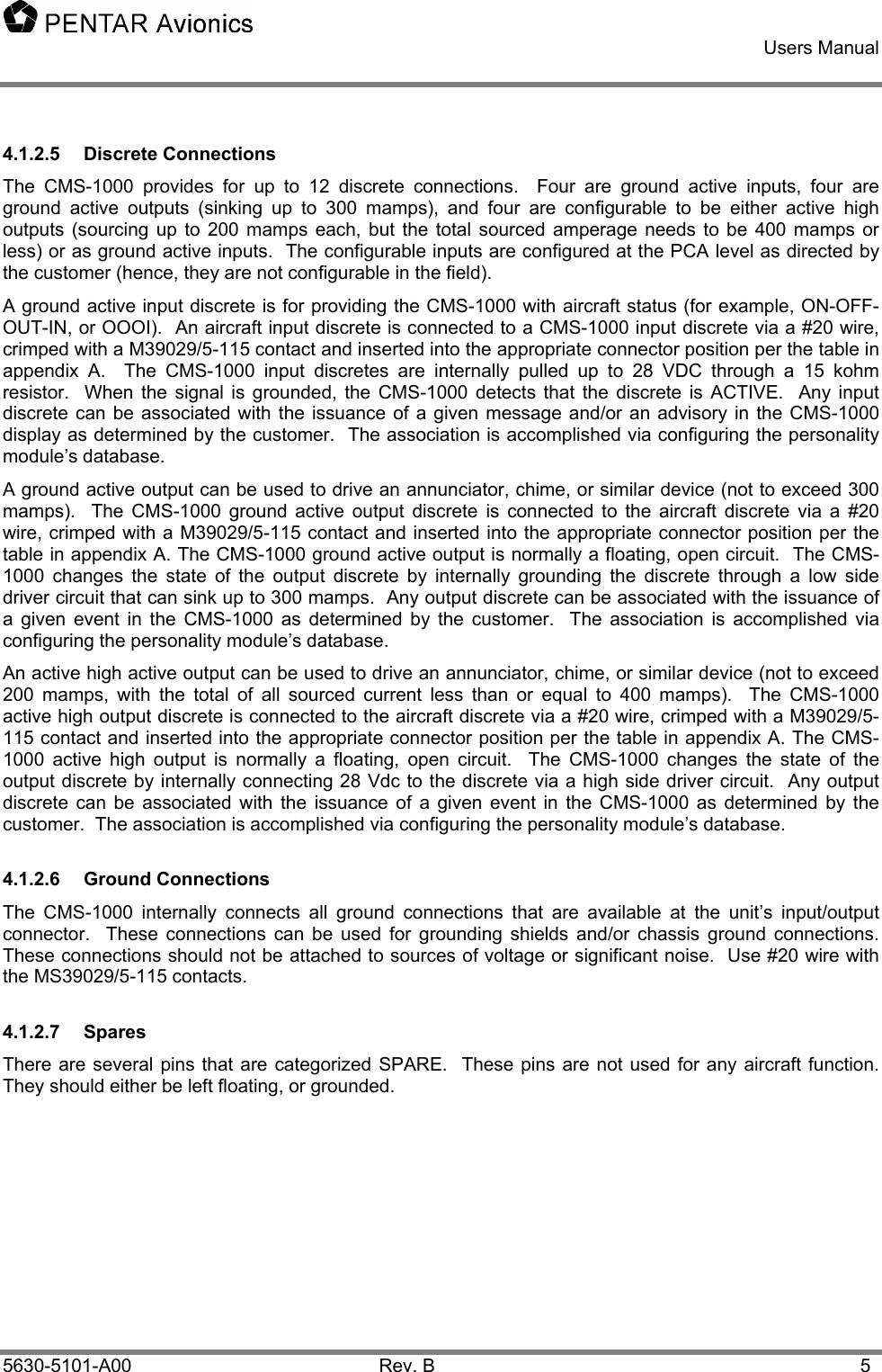
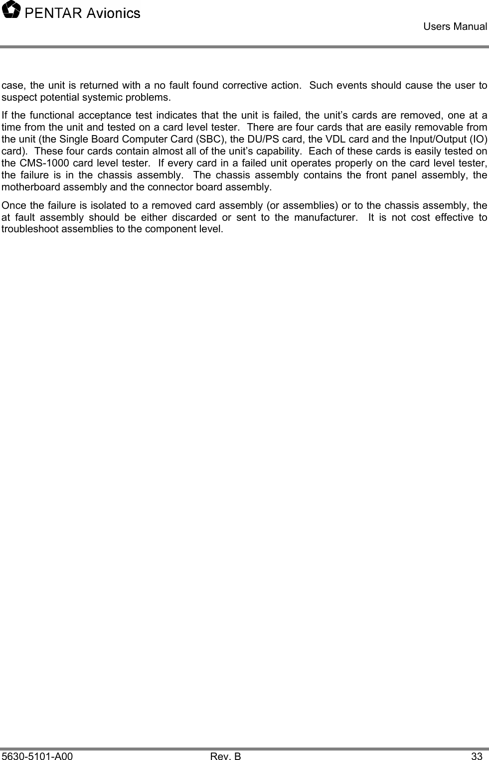
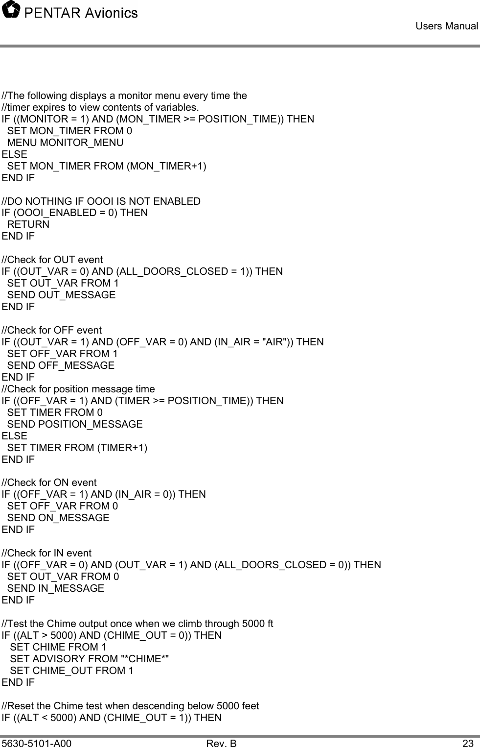
![Users Manual 5630-5101-A00 Rev. B 6 5 Configuring the CMS-1000 The CMS1000 contains a default configuration and database that provides basic functionality when the personality module is either missing or invalid. The configuration can be modified by downloading a configuration using the laptop loader or manually using the configuration editor menus. 5.1 Downloading a configuration The configuration file is a text file that can be modified by any text editor (Windows notepad is a good choice). It is in the form of an initialization file (.INI) with comments describing each field. The initial section of the file has the header “[Aircraft]”. CAUTION: This is the only section the user should modify as changing fields in other sections may prevent the CMS1000 from operating correctly. To download the configuration to the CMS1000 you must connect the laptop loader to the CMS1000 Ethernet port. Start CMSTest and wait for the title bar to indicate that “CMSTest is connected to CMS”. Press the “Write Config” button and select the desired configuration file. The file will be downloaded and written to the personality module. The CMS1000 will automatically reboot. 5.2 Editing a configuration On the CMS1000 display select the CONFIG menu. Note that the path to get to the CONFIG menu may change depending on the user database. In the CONFIG menu select “USER EDIT” to edit the user fields or “SYS EDIT” to edit the system fields (editing the system fields is NOT recommended for the user). After modifying any desired fields press the return key or RETURN LSK. The confirmation menu is displayed. The selection field defaults to YES. Pressing the LSK cycles the selection to NO, to CANCEL, and back to YES. Pressing the return key or RETURN LSK accepts the selection. If YES is selected the password menu is displayed next. Type the appropriate password (default is “USER00” for the user config and “PENTAR” for the system config). Press ENTER to enter the password. The configuration will be written to the personality module and the CMS1000 will automatically reboot. 5.3 Downloading a database The database file is a pair of text files that can be modified by any text editor (Windows notepad is a good choice). The database is a simple, specialized, language for specifying MENUs, variables, ACARS message contents, etc. The syntax for the database language is in the sections following. It is divided into two files that we call the CORE and USER databases. The core database is always named CMS1000_core_db.txt and contains all the CMS system critical definitions of variables, functions, and ACARS messages and can only be modified by Pentar. It is protected by a special check code that allows any modifications to be detected by the compiler. If the core database is modified the compiler will display an error message and refuse to compile the database. The user database is completely defined by the user. Several of the core functions can be replaced in the user database to customize the functionality of the CMS as noted in the syntax sections below. After modifying a database it must be compiled with CMSComp then downloaded with CMSTest on the laptop loader.](https://usermanual.wiki/Spectralux/13281-1/User-Guide-426812-Page-13.png)
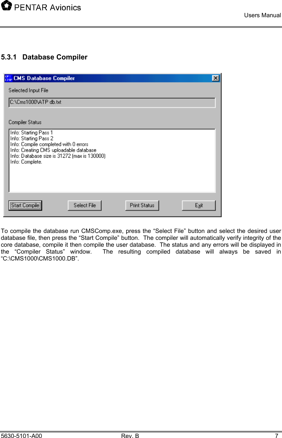
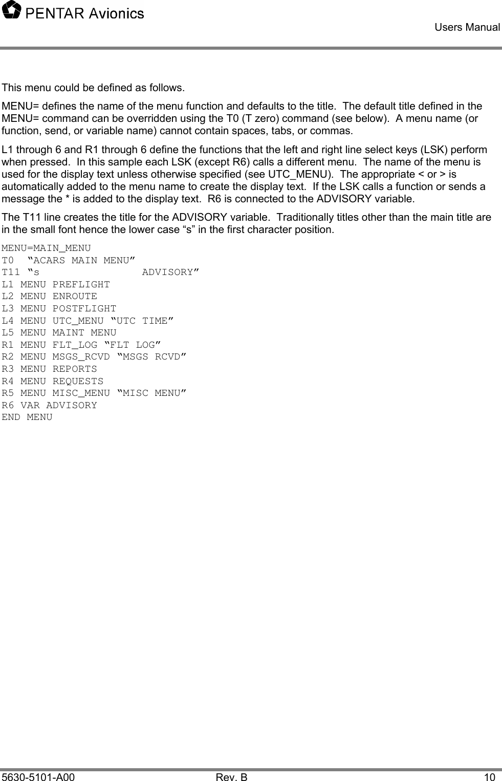
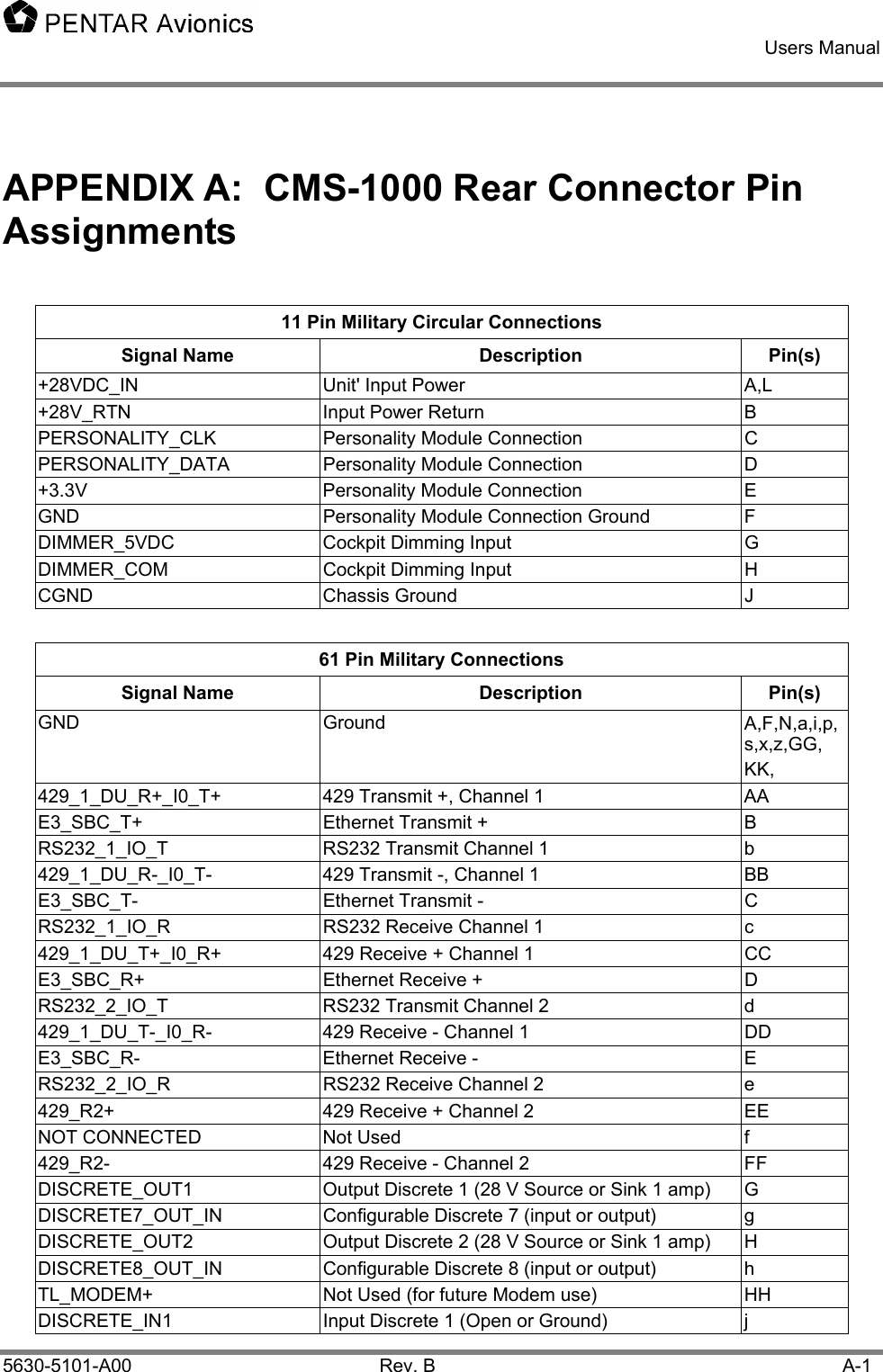
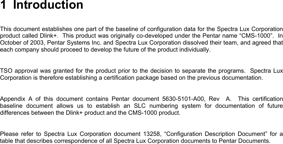
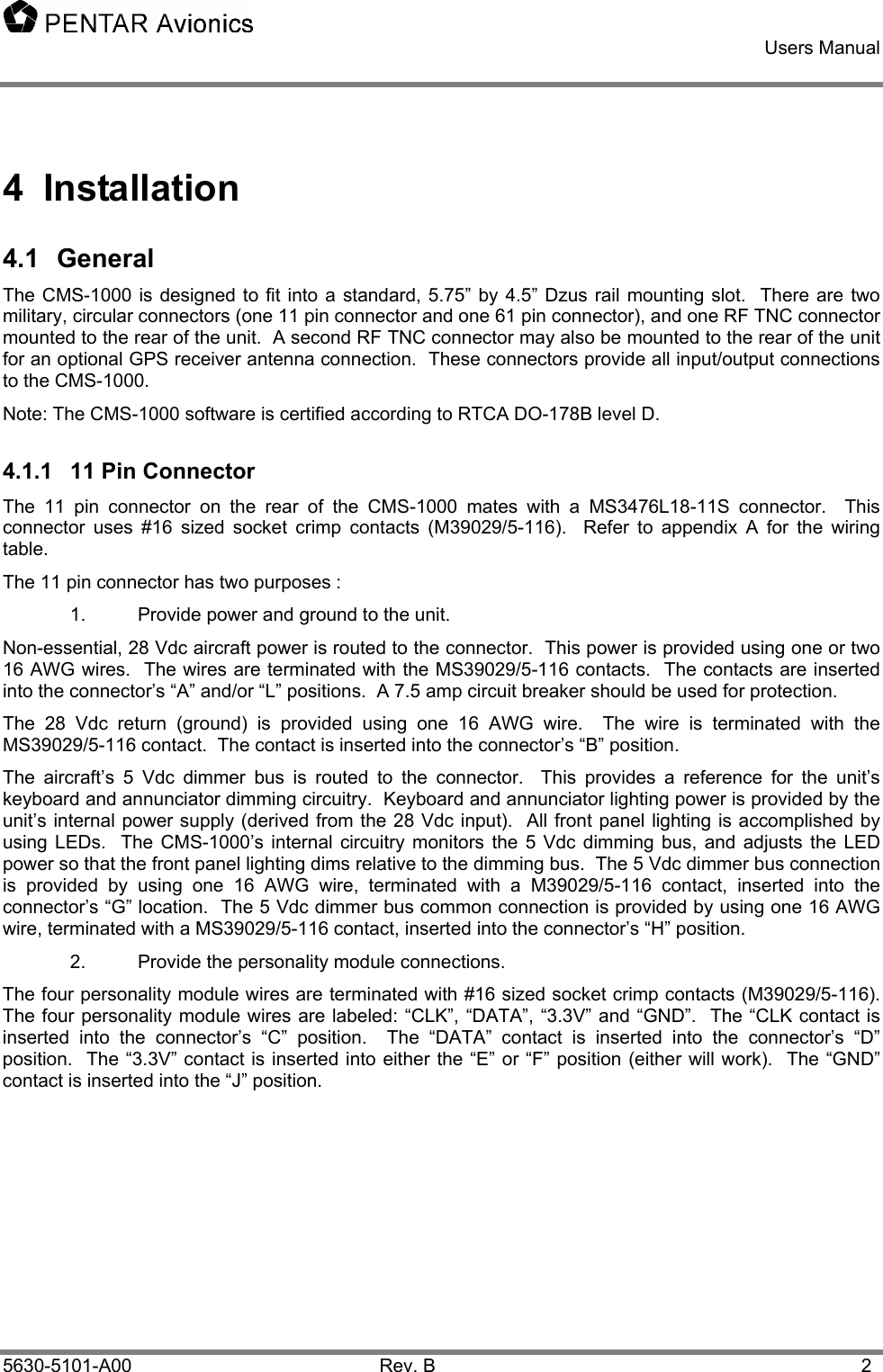
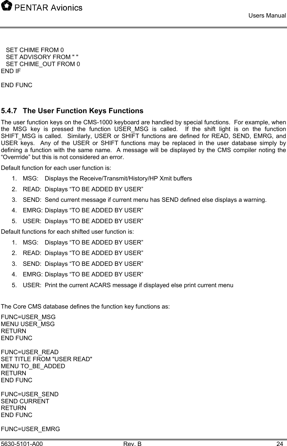
![Users Manual 5630-5101-A00 Rev. B 11 Second Example: INIT DATA T0 FLT NO DATE T1 L1 - NNNN NN - R1 T2 DEPT DEST T3 L2 - AAAA AAAA - R2 T4 ETD ETE T5 L3 - HHMM HHMM - R3 T6 GW MSG BUFFER T7 L4 - NNNNN [RECEIVE] - R4 T8 T9 L5 - AUTO_INIT* - R5 T10 T11 L6 - <RETURN TOGGLE FN* - R6 T12 SCRATCH PAD Figure 4.2-2 Example Init Data Menu The following defines the above menu and functions called from it. In this menu the text fields above the LSKs are defined by the T1, T3, T5, T7 text commands. Text commands specify the text for whole width of the display. Text command can contain formatting characters (the lower case “s” selects a small font here) and variable names. See formal syntax for LSKs. This example associates the LSKs to variables (VAR command and SELECT command). By default the current value of the user variable is displayed in the appropriate LSK field in the format defined for that variable (see User Variable Definitions.) In this example, left line select key 6 (L6) is connected to the RETURN function that returns to the calling menu. “<RETURN” is displayed in the L6 field. R5 calls a function named AUTO_INIT. By default the text “AUTO_INIT*” is displayed in the R5 field (it”s a function hence the * instead of a >). AUTO_INIT contains statements to set the variables used in the display to the current value of other user variables (presumably variables extracted from 429 or discrete inputs – see User Variable Definitions) and a constant then redisplays the INIT_DATA menu. (Note: when the same menu is redisplayed or reselected the data on the menu is updated but the menu is not added again to the call stack). The SELECT command displays the current selection of a variable from its selection list (see User Variable Definitions). It is identified with the “[“ and “]” around the variable contents. Each press of its LSK selects the next item in the selection list in a circular fashion. INIT_DATA has 4 pages. The NEXT and PREV commands link the pages together. They are accessed using the NEXT/PREV LSK key. INIT_DATA_2 shows an example of a text line including a variable to display and specifying the underline font for the variable contents. Another way to create multiple page menus is with the PAGES and ITEMS commands. See the example of the MESSAGE menu below that displays the current ACARS message buffer. The PAGES are set to zero to tell the CMS to figure out how many pages this message will require based on the number of ITEMS per page and use that number as the max on the display. The @MSG special function knows which page it is on to display the appropriate data. MESSAGE also shows an example of the DELETE command to delete the current ACARS message from the buffer and the PRINT command to print the contents of the current message when a printer is attached to the CMS.](https://usermanual.wiki/Spectralux/13281-1/User-Guide-426812-Page-18.png)
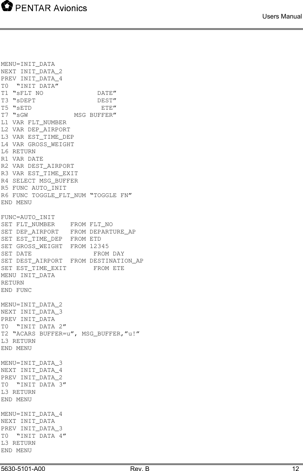
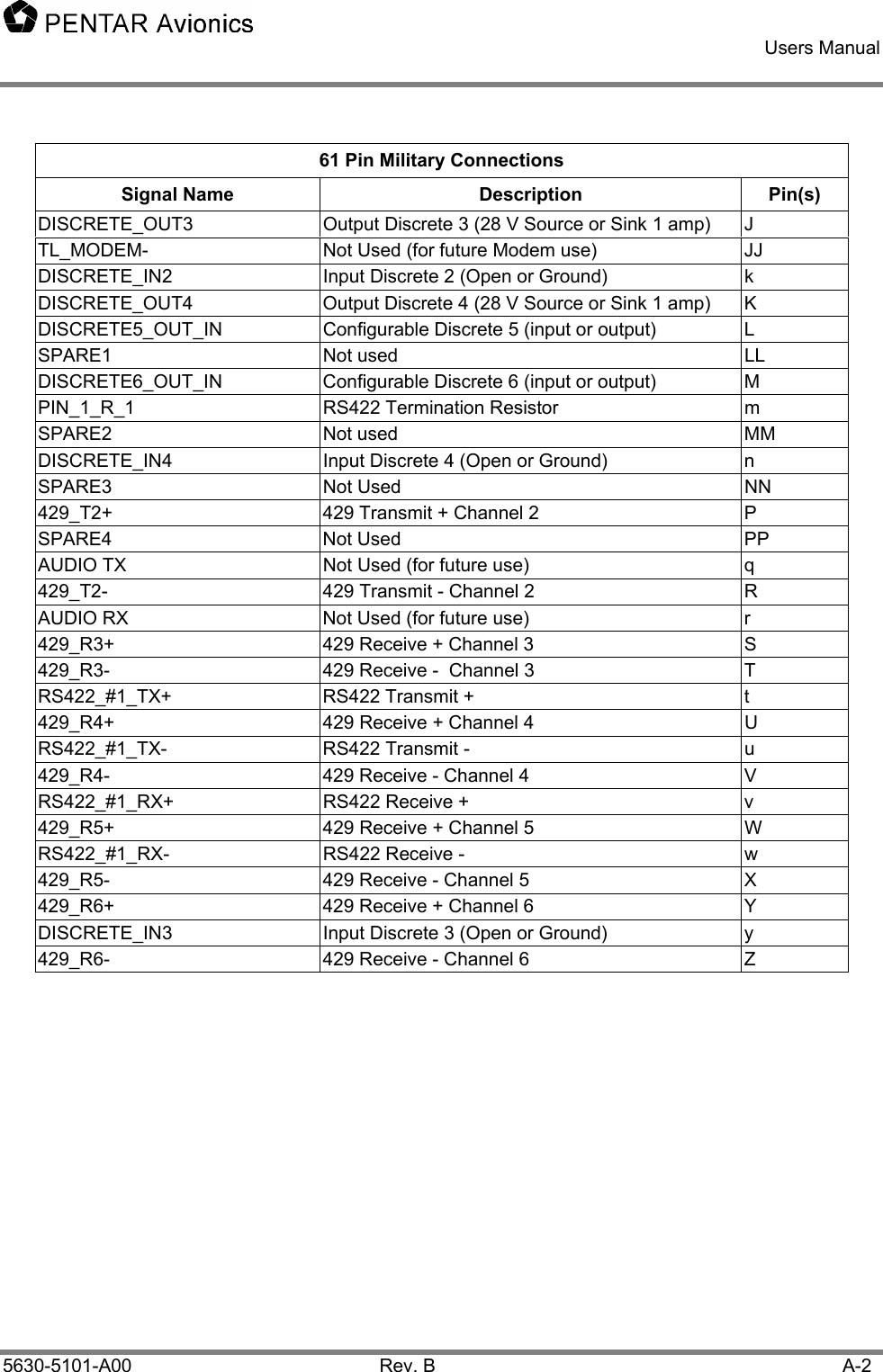
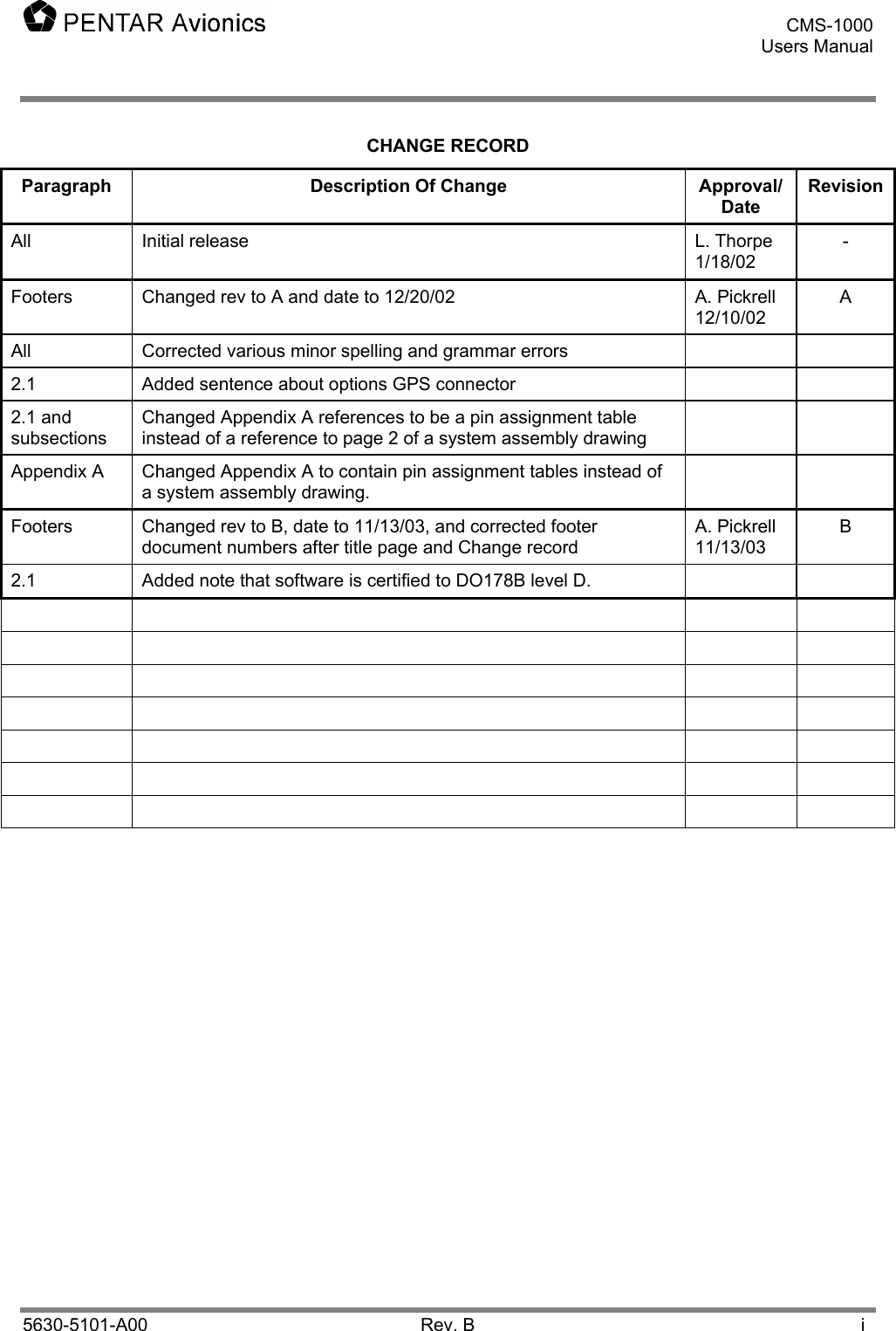
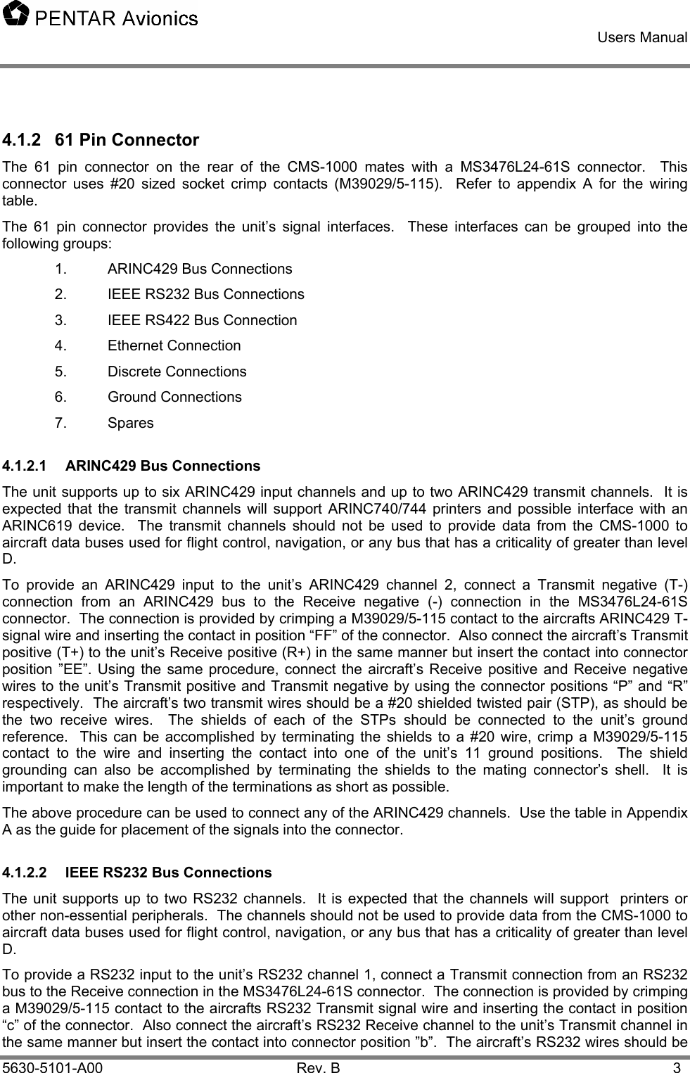
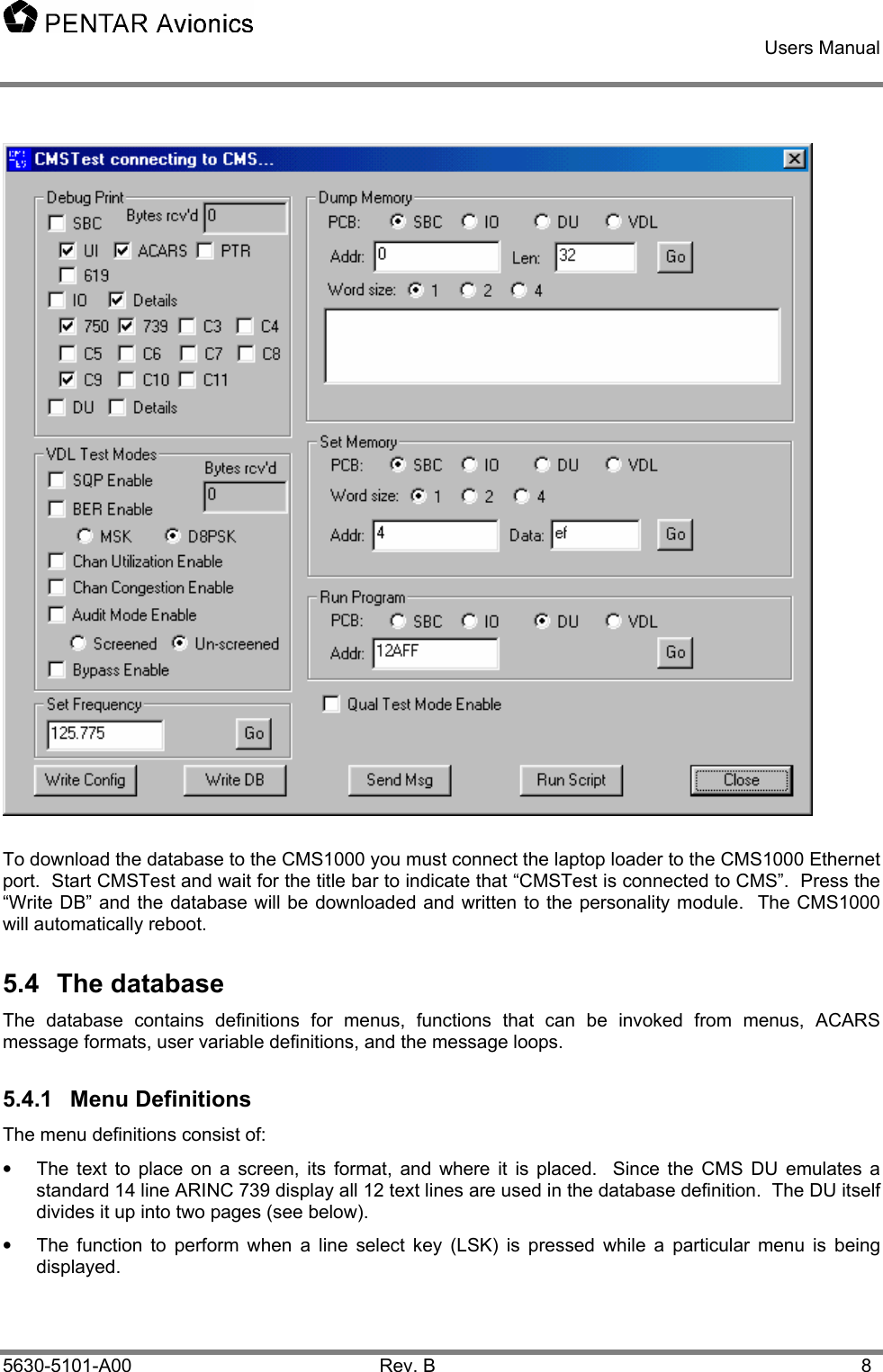
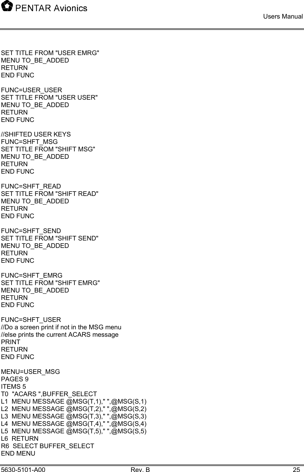
![Users Manual 5630-5101-A00 Rev. B 13 MENU=MESSAGE PAGES 0 ITEMS 9 T0 "s",@MSG(T,0) T1 @MSG(L,1) T2 @MSG(L,2) T3 @MSG(L,3) T4 @MSG(L,4) T5 @MSG(L,5) T6 @MSG(L,6) T7 @MSG(L,7) T8 @MSG(L,8) T9 @MSG(L,9) L5 DELETE R5 PRINT L6 RETURN END MENU A note about updating personality module data and the PASSWORD command: When a password is attached to a menu it is only used in conjunction to updating the personality module. When one or more variables are modified whose source is the personality module the variables are held in temporary storage. When returning from the menu that they were modified in the CMS verifies that it is on the ground (personality module changes are not allowed in air). Then a menu will be displayed confirming changes to the personality module. The user selects YES or NO and presses RETURN. Finally a password menu is displayed. The user enters the password then presses the ENTER key (this is intentionally changed from the RETURN key used to exit other menus). The user is allowed three attempts to enter a correct password. If the aircraft is in air or the user answers NO to the confirmation or cannot enter a correct password in three attempts the personality module changes will be discarded and the original values will be used. Otherwise, the data will be written to the personality module and the CMS will restart. 5.4.1.1 Formal Syntax <menu block>: MENU=<menu name> [<menu command>…] END MENU <menu command>: <Pages command> | <Items command> | <Password command> | <text command> | <LSK command> | <Next command> | <Prev command> <Pages command>: “PAGES” <max pages> <max pages>: “0” though “9” Note: When <max pages> is set to zero the CMS will interrogate the current selected message and determine how many pages it will use based on the ITEMS value. <Items command>: “ITEMS” <items per page> <items per page>: “1” through “9” <Password command>: “PASSWORD” <variable name> <Next command>: “NEXT” <menu name> <Prev command>: “PREV” <menu name> <text command>: “T”<line number> <text line> <line number>: “0” through “12”](https://usermanual.wiki/Spectralux/13281-1/User-Guide-426812-Page-20.png)
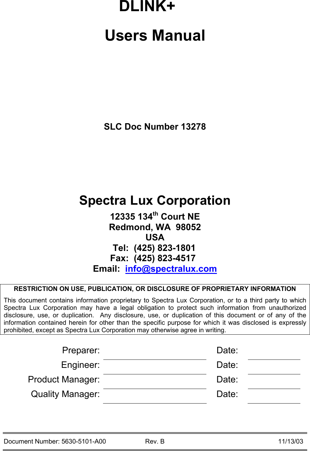
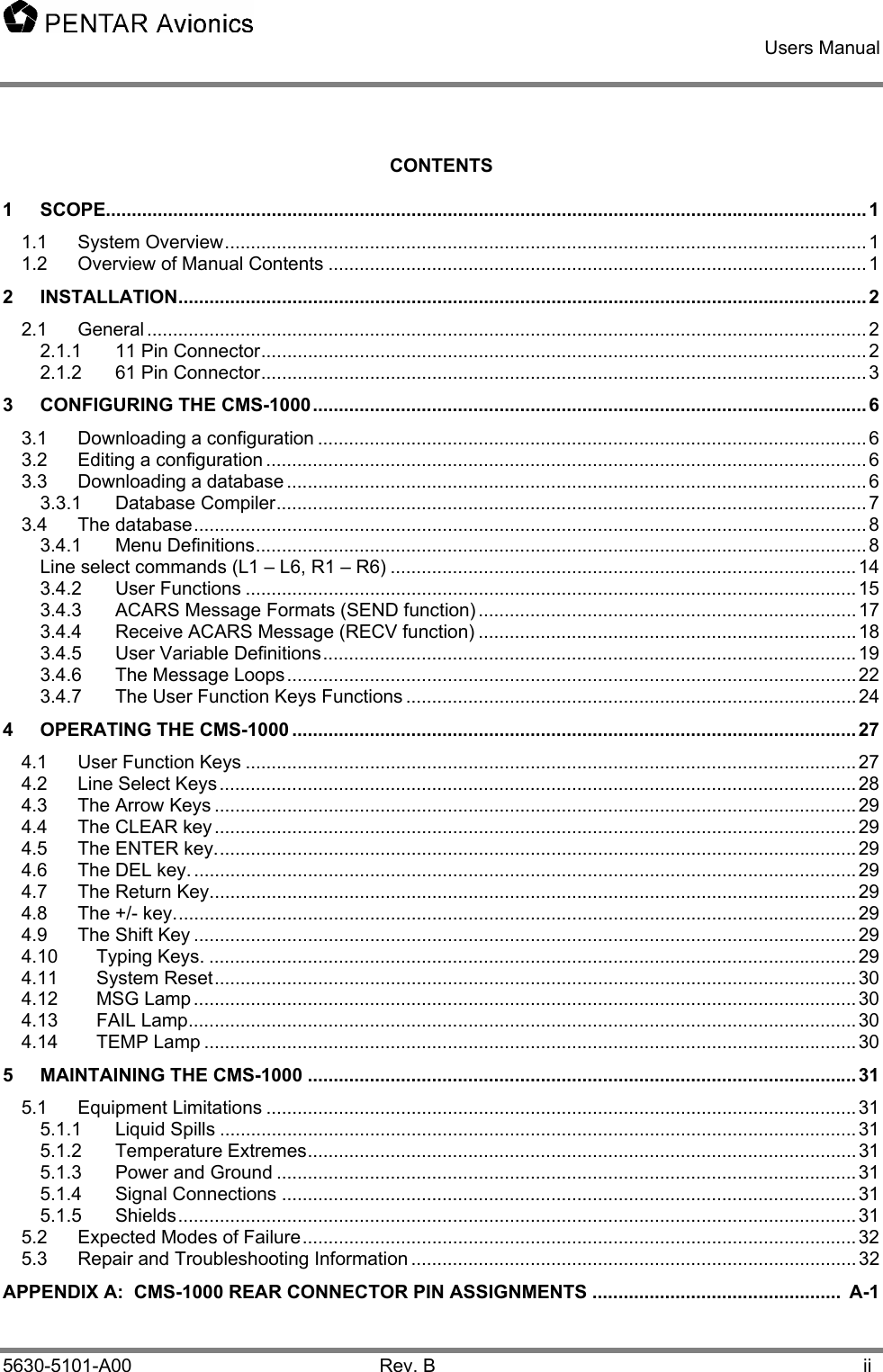
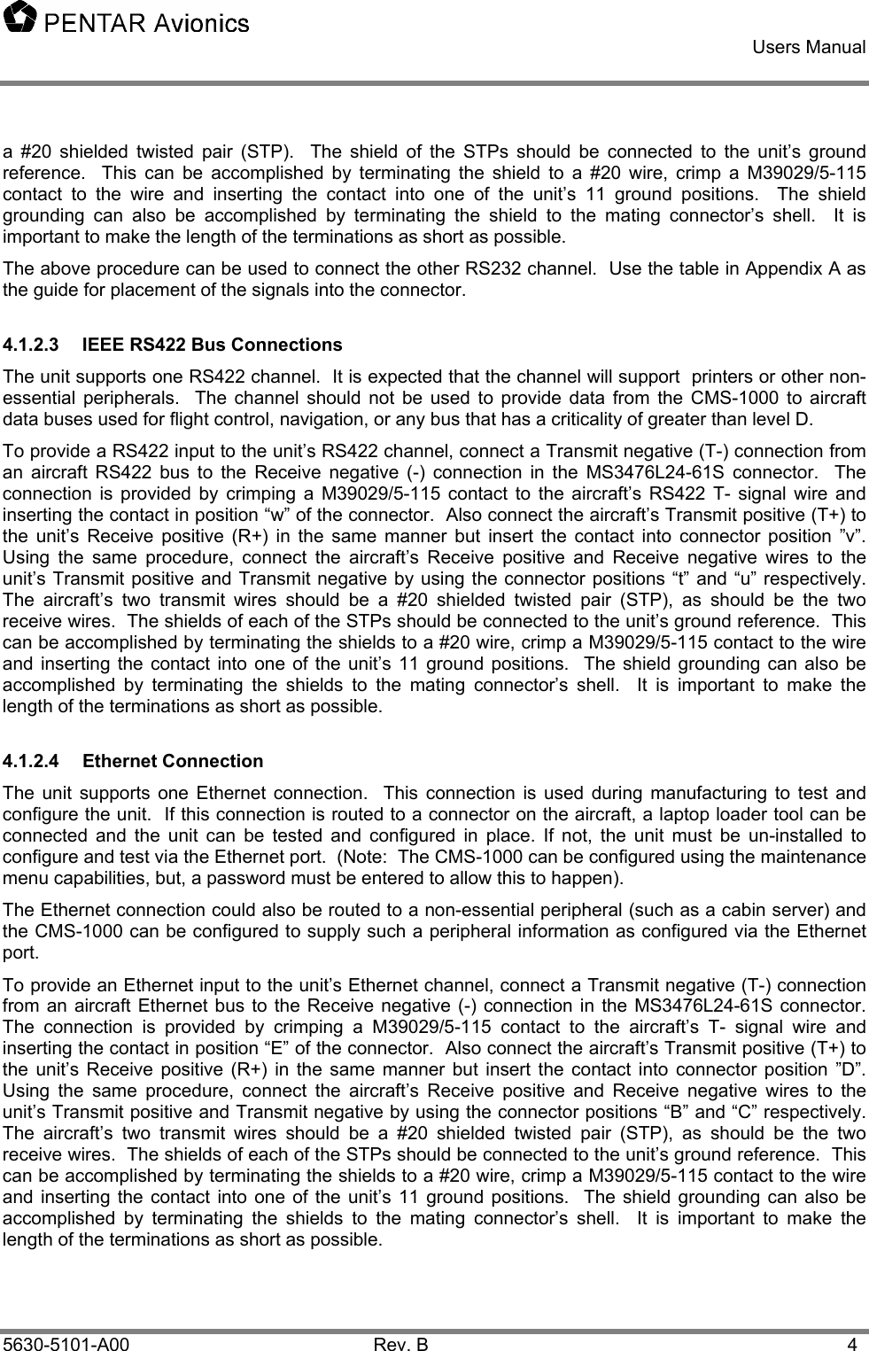
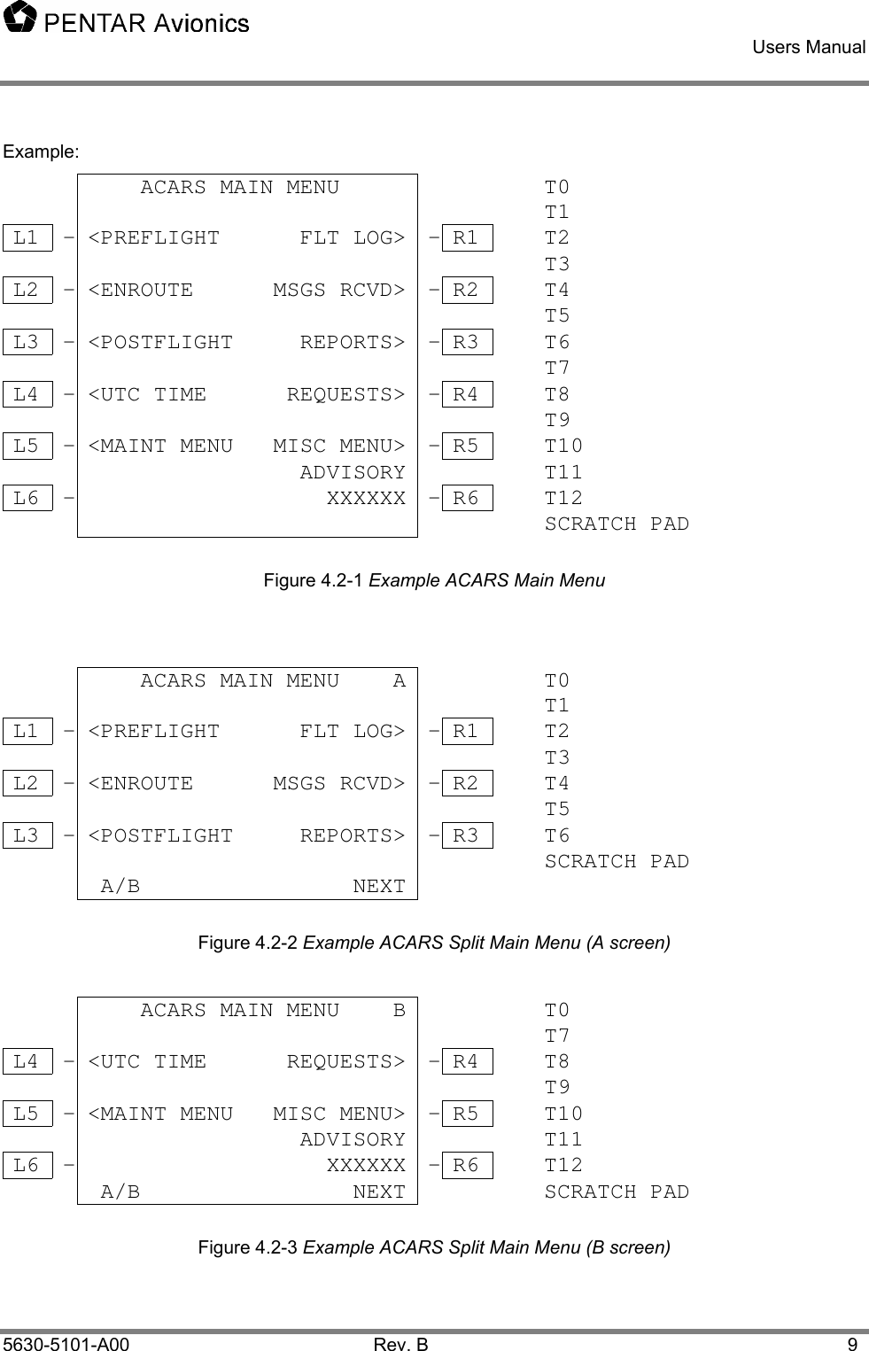
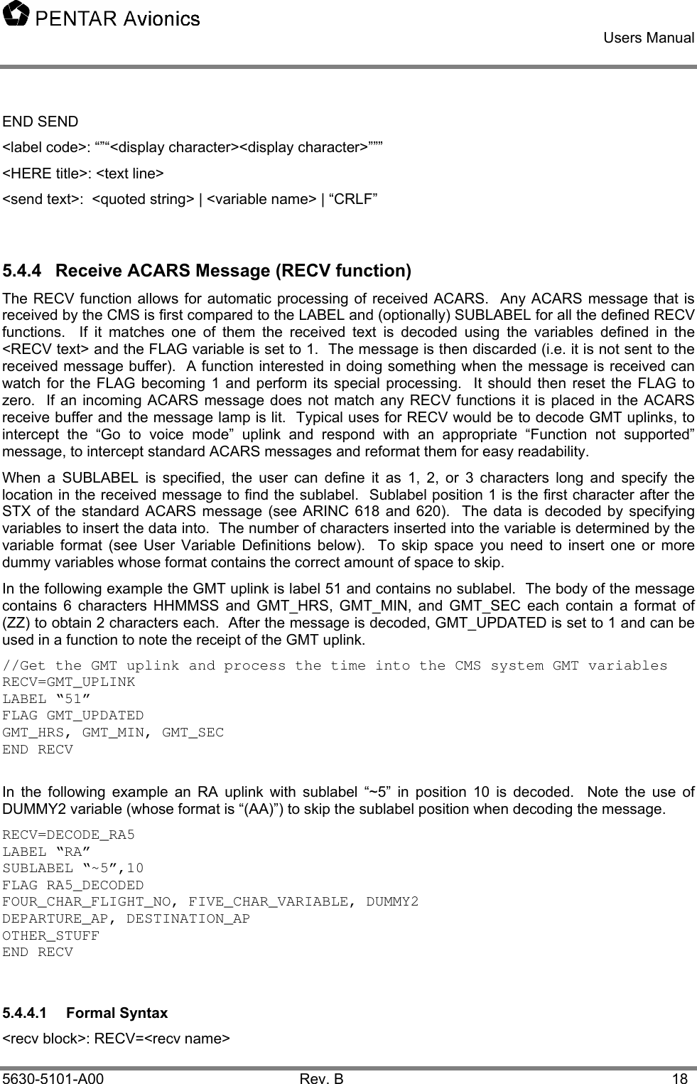
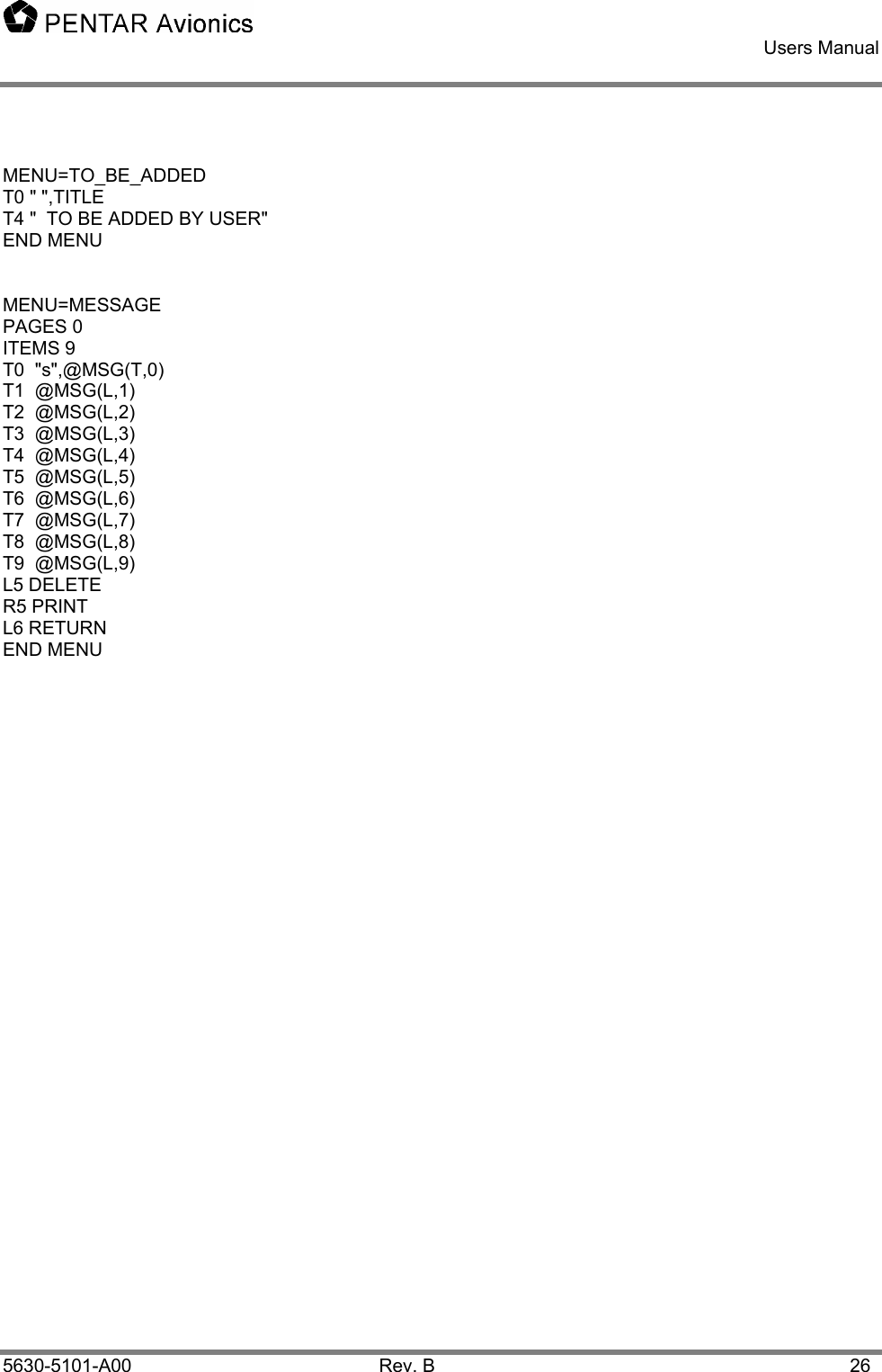
![Users Manual 5630-5101-A00 Rev. B 14 <text line>: <text token>[,<text token>…] <text token>: <quoted format string> | <variable name> | <special function> <quoted format string>: “[<string character>…]” <string character>: <display character> | <format character> <quoted string>:“””[<display character>…]””” <display character>: <alpha character> | <digit> | <symbol> <alpha character>: upper case characters “A” through “Z” <digit>: “0” through “9” <symbol>: “!” | “@” | “#” | “$” | “%” | “^” | “&” | “*” | “(“ | “)” | “+” | “-” | “\” | “/” | “.” | “ “ <format character>: “s” | “r” | “u” | “v” | “f” <variable name>: <alpha character> | <number> [<alpha character> | <number> | “_”…] <special function>: “MSG(“<msg code>,<msg item>”)” <msg code>: “T” | “S” | “L” <msg item>: “1” through “9” Notes: <text line> and <variable name> are limited to 24 characters <text line> length is determined by the number of non <format characters> plus the format length of each <variable name>. <format character> is defined as follows: “s” Small font “r” Regular font “u” Underline (toggle) “v” reverse Video (toggle) “f” Flashing (toggle) <format characters> apply only to the current <text line>. Default is regular font and no underline, reverse video, or flashing if no <format character> is specified. Items indicated as “toggle” turn on the format on the first occurrence and turn it off on the next occurrence. <msg code> is defined as “T” for the title line of the message, “S” is the status (OLD or NEW) for the message, and “L” is the line from the message. The title line of a message defaults to the label and the time it was placed in the buffer. This can be changed using the SEND “HERE” function (see SUND functions below). Line select commands (L1 – L6, R1 – R6) <LSK command>: “L”< LSK number> <command> [<text line>] | “R”< LSK number> <command> [<text line>] < LSK number>: “1” through “6” <command>: “MENU” <menu name> | “SEND” <send name> | “FUNC” <func name> | “VAR” <variable name> |](https://usermanual.wiki/Spectralux/13281-1/User-Guide-426812-Page-21.png)
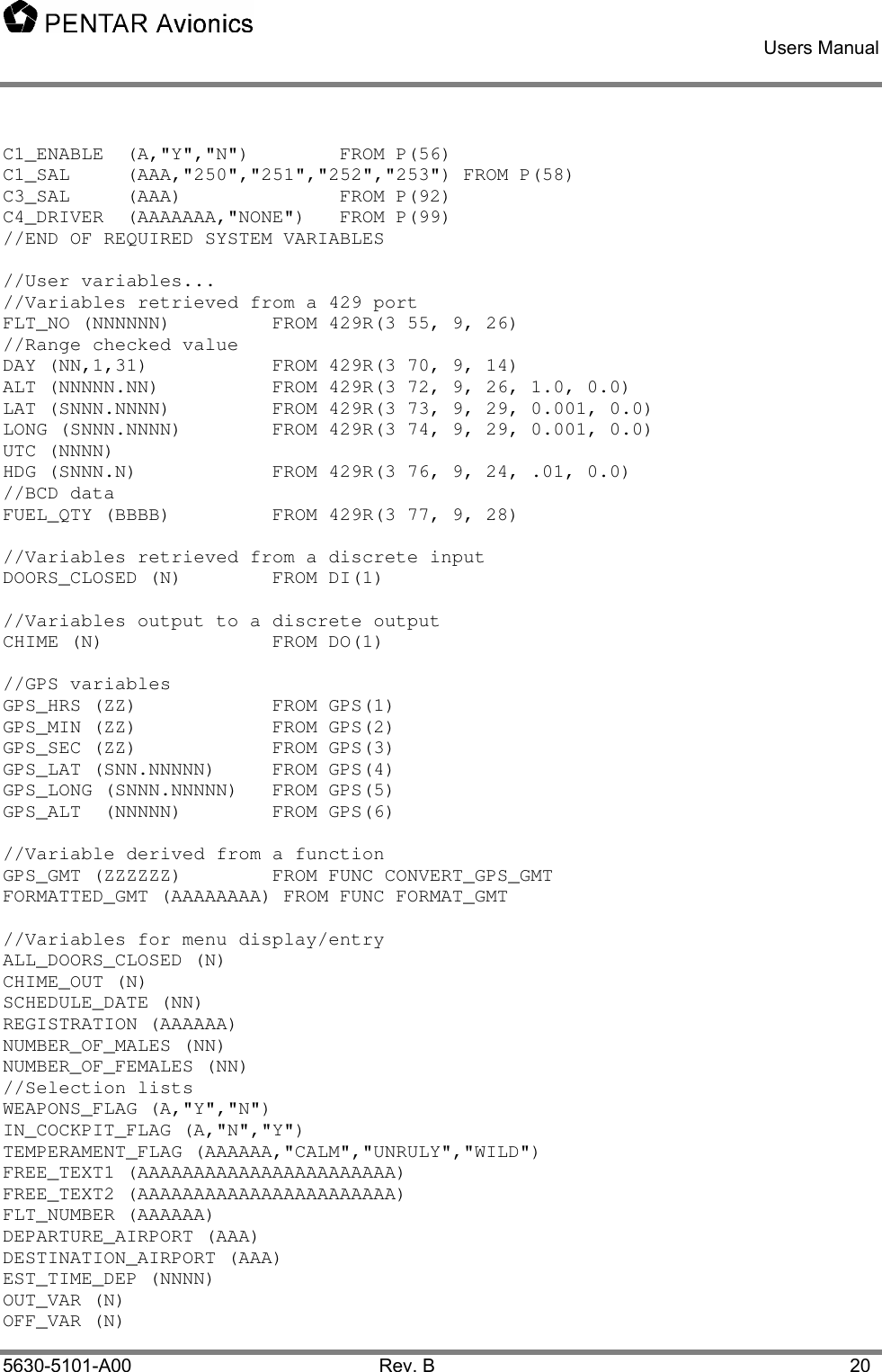
![Users Manual 5630-5101-A00 Rev. B 15 “SELECT” <variable name> | “RETURN” | “DELETE” | “PRINT” <menu name>: <variable name> <send name>: <variable name> <func name>: <variable name> Note: For Line Select commands the <text line> is used to override the default display text. The default display text for MENU is the <menu name>, FUNC is <func name>, SEND is “SEND”, RETURN is “RETURN”, PRINT is “PRINT”, and DELETE is “DELETE”. For the VAR and SELECT commands the <text line> is ignored since the current value of the variable is always displayed. When <command> is MENU or RETURN the display text is preceded by the “<“ character for Left LSKs and succeeded by a “>“ character for Right LSKs. For FUNC, SEND, PRINT and DELETE the display text is preceded by the “*” character for Left LSKs and succeeded by a “*” character for Right LSKs. For SELECT the contents of the variable is surrounded by square brackets “[“ and “]”. Each press of its LSK selects the next item in the selection list. No characters are added to the display text for the VAR command. 5.4.2 User Functions User functions consist of statements to invoke menus (MENU), call other user functions (FUNC), set values in user variables (SET), send ACARS messages (SEND), and perform simple logic statements (IF, THEN, ELSE). For example, if the function TOGGLE_FLT_NUM is invoked by pressing LSK R6 in the INIT_DATA menu the function might look like: FUNC=TOGGLE_FLT_NUM IF (FLT_NUMBER = 86) THEN SET FLT_NUMBER FROM 68 ELSE SET FLT_NUMBER FROM 86 END IF MENU INIT_DATA RETURN END FUNC If the value of FLT_NUMBER is 86 then it is changed to 68 and visa-versa. Then the INIT_DATA menu is redisplayed. The IF command can compare a variable to another variable or a constant. It can be followed by AND or OR followed by another comparison. See MESSAGE_LOOP for additional examples. Parenthesis are required (see formal syntax). Any number of statements can be between the IF and the ELSE (the IF block) and the ELSE and the END IF (the ELSE block). The ELSE block is optional. An IF must always end with END IF. Nested IFs are allowed. Allowed comparison operators are: = (equal), <> (not equal), <= (less than or equal to), >= (greater than or equal to), > (greater than), or < (less than). Allowed arithmetic operators are + (add), - (subtract), * (multiply), / (divide). A string concatenation operator & is also allowed. Note that parenthesis are important in the database syntax of the IF and the SET statement. In simple terms, an IF THEN requires an expression that evaluates to a zero or not zero and SET can set a value FROM an expression. An expression must always be in parenthesis and has the general format of “(X operator Y)”. For example, the expression could be “(X = Y)” where X is compared to Y. X itself can be an expression say “(A / B)” so the total expression would be “((A / B) = Y)”. Other examples:](https://usermanual.wiki/Spectralux/13281-1/User-Guide-426812-Page-22.png)
![Users Manual 5630-5101-A00 Rev. B 16 • IF ((ALT > 10000) AND (AIRSPEED <150)) THEN • SET UPDATE_FLAG FROM (GMT_UPDATED AND (FP_UPDATED OR MENU_UPDATED)) • SET GMT FROM FUNC CONVERT_GMT • SET FORMATTED_GMT FROM ((((GMT_HRS & “:”) & GMT_MIN) & “:”) & GMT_SEC) Expressions are evaluated left to right with NO operator precedence so use parenthesis to make it unambiguous. Note that all variables are global in the CMS and may be defined in either the core or user database. • The SET command sets the value of a variable. The value can be a variable, a constant, an arbitrary expression, or the result of a function call. When setting a variable to a constant or another variable the parenthesis are optional. See formal syntax below. • The MENU command invokes a menu. The function puts the menu into the display queue and continues (i.e. does not wait for the menu to be displayed or accept user input). • The SEND command calls the SEND function. Similar to the MENU it puts the ACARS message in the transmit queue and continues. • The FUNC command calls another function. Execution continues after the called function returns. • The RETURN command exits the function and may return a value. • The FUNC must always end with END FUNC. 5.4.2.1 Formal Syntax <func block>: FUNC=<func name> [<func command>…] END FUNC <func command>: <set command> | <menu command> | <if block> | <send command> | <return> | <func call> <set command>: “SET” <variable name> “FROM” <data source> <data source>: <variable name> | <constant> | <expression> | <func call> < expression >: “(“ <variable name> | <constant> | <variable name> <operator> < expression > | <variable name> <operator> <variable name> | <variable name> <operator> <constant > | <expression> <operator> <expression> “)” <operator>: “+” | “-” | “*” | “/” | “AND” | “OR” | “>“ | “<“ | “<>“ | “=“ | “<=“ | “>=“ | “&” <menu command>: MENU <menu name> <send command>: SEND <send name> <func call>: FUNC <func name> <return>: RETURN [<variable name>] <if block>: IF < expression > THEN [<func command>…] [ELSE](https://usermanual.wiki/Spectralux/13281-1/User-Guide-426812-Page-23.png)
![Users Manual 5630-5101-A00 Rev. B 17 [<func command>…]] END IF Note: the compiler will verify that the contents of a <constant> is consistent with format of the associated variable. 5.4.3 ACARS Message Formats (SEND function) ACARS messages are defined in a SEND function that allows the user to combine text and the current value of user variables into a correctly formatted message and transmit it to the ground. //Create an emergency ACARS message SEND=EMERGENCY_REPORT_MSG LABEL “00” “ 01 HIJACK “,FLIGHT_NO,”/” SCHEDULE_DATE,” “,DEPARTURE_AP,”/” DESTINATION_AP,” “,REGISTRATION,CRLF “/MAL”,NUMBER_OF_MALES “/FEM”,NUMBER_OF_FEMALES “/WPN”,WEAPONS_FLAG “/CPT”,IN_COCKPIT_FLAG “/TMP”,TEMPERAMENT_FLAG,CRLF ER_FREE_1,ER_FREE_2,ER_FREE_3 END SEND The message is created by concatenating all the parts into a long string. The constant text must be in double quotes. The fields are separated by carriage returns, commas, tabs, or spaces. As many lines MAY be used as desired and extra spaces or tabs between fields are ignored. A special “variable” is CRLF that inserts a carriage return/line feed into the message. The LABEL command is required in the send block. The number of characters and format for variables is defined in the user variable definitions. In the user database only the following labels are allowed: • Q7, 5Z, 00, 5D, 5U, 7A, 7B, or RB There are two special labels, HERE and ETHER (or ETHERNET). • HERE directs the message directly to the CMS receive buffer and turns on the MSG lamp. This allows the CMS to send an arbitrary message to the pilots or to reformat a received message to be more easily read. • ETHER (or ETHERNET) directs the message to the CMS Ethernet interface. An application with the ability to receive these messages must be running or the messages will be lost. The Ethernet application can be running on a Pentar JetLan or similar device. It can operate as a simple flight data recorder, perform FOQA type flight analysis, store maintenance messages for delivery to the airline maintenance shop after landing, etc. A special SEND function name is defined called CURRENT. Putting “SEND CURRENT” in a FUNC will cause the LSK associated with a SEND in the current menu to be selected. If the current menu has no SEND defined an error message “NOTHING TO SEND” will be displayed on the scratch line. 5.4.3.1 Formal Syntax <send block>: SEND=<send name> LABEL <label code> | “HERE”,<HERE title> | “ETHER” | “ETHERNET” [<send text>…]](https://usermanual.wiki/Spectralux/13281-1/User-Guide-426812-Page-24.png)
![Users Manual 5630-5101-A00 Rev. B 19 LABEL <label code> [SUBLABEL <sublabel code>,<sublabel pos>] FLAG <var name> [<variable name>…] END RECV <label code>: “””<display character><display character>””” <sublabel code>: “”“<display character>[<display character>][<display character>]””” <sublabel pos>: 1..220 5.4.5 User Variable Definitions User variables are defined so that the system can allocate appropriate storage, define the display/conversion format and allowed values. Also the data source (FROM a 429 receiver, a discrete input, or derived from other variables or constants) and data sink (like a discrete output) are defined. There are several predefined variables for the system (see the sample compiler source file). The user variables are defined after them or in the user database file. The item in parenthesis after a variable name describes the variable’s format and range or selection list. For formats “A” is any ASCII character, “N” is a number, “S” specifies a signed numeric, “B” is BCD characters, “Z” specifies leading zeros, “P” is a password (Displays with “*”s). Numeric and character values are restricted to the field size. A variable’s initial value is the first item in the selection list if it is included, otherwise it is zero for numeric data and a blank for ASCII/password data. FROM defines the source of the data. A source beginning with 429R come from the 429 receive ports. The port number, label value, start and end bit range must be specified. Optionally a slope and offset to convert the raw value to engineering units is allowed. A source beginning with DI comes from a discrete input. Only one bit is allowed resulting is a value of zero or one. A source of DO goes to the discrete output. A zero is written if the value of the variable is zero else a 1 is written. A source of P(n) refers to the personality module. “n” is the offset in the personality module to read/write the variable. A source of GPS(n) refers to the n’th of the decoded GPS data. The source can also be a simple expression or a function call. VARS //THE FOLLOWING VARIABLES MUST BE DEFINED FIRST AND IN THIS ORDER ADVISORY (AAAAAAAA) AIRCRAFT_7C_ADDR (AAAAAAA) FROM P(232) AIRCRAFT_ICAO_ADDR (NNNNNNNN) FROM P(240) FLIGHT_NUMBER (AAAAAA) CAT_MODE (AAA, "ALL","A","B","A2","B2","2") FROM P(253) FREQ_MSK_1 (NNN.NNN) FROM P(257) FREQ_MSK_2 (NNN.NNN) FROM P(265) FREQ_MSK_3 (NNN.NNN) FROM P(273) PREKEY_D8PSK (NN) FROM P(324) TM1_D8PSK (NNN) FROM P(327) TM2_D8PSK (NNN) FROM P(331) M1_D8PSK (NNNNN) FROM P(335) PERSISTANCE_D8PSK (N.NNN) FROM P(341) IN_AIR (AAA,"GND","AIR") BUFFER_SELECT (AAAAAAAA,"RECEIVE","TRANSMIT","HISTORY") DU_CONFIG (N,1,2) FROM P(36) C1_DRIVER (AAAAAAA,"A750",”A750E”) FROM P(48)](https://usermanual.wiki/Spectralux/13281-1/User-Guide-426812-Page-26.png)
![Users Manual 5630-5101-A00 Rev. B 21 TIMER (NNNNN) MON_TIMER (NNNN) OOOI_ENABLED (N) //Constant value POSITION_TIME (NNNNN) FROM 10 BOARDED_FUEL (NNNNN) CAPT_FO (A,”C”,”F”) MONITOR (N,0,1) END VARS 5.4.5.1 Formal Syntax VARS [<variable definition>…] END VARS <variable definition>: <variable name> <var format> [“FROM” <source>] <var format>: “(“<unsigned format> | <alpha format> | <signed format> | <zero format> | <BCD format> | <password format> [“,”<range>|<value list>]”)” <unsigned format>: “N”[“N”…][“.”][“N”…] <alpha format>: “A”[“A”…] <BCD format>: “B”[“B”…][“.”][“B”…] <zero format>: “Z”[“Z”…] //integers only <signed format>: “S”<unsigned format>|<BCD format> <password format>: “P”[“P”…] <source>: <429 input> | <discrete input> | <discrete output> | <personality> | <GPS input> | <simple expression> | <func call> <429 input>: “429R(”<429port> <label> <start bit> <end bit> [<slope> [<offset>]]”)” <429port>: “1” through “6” <label>: “000” through “377” Note: <label> is specified in octal per 429 convention. <start bit>: “9” through “32” <end bit>: “9” through “32” <slope>: <float number> <offset>: <float number> <float number>: [“+” | “-“] <digit>[<digit>…] [“.”] [<digit>…] [“E”<digit><digit>]](https://usermanual.wiki/Spectralux/13281-1/User-Guide-426812-Page-28.png)
![Users Manual 5630-5101-A00 Rev. B 22 <constant>: <float number> | <quoted string> <discrete input>: “DI(”<discrete input port>”)” <discrete input port>: “1” through “8” <discrete output>: “DO(”<discrete output port>”)” <discrete output port>: “1” through “4” <personality>: “P(“<personality address>”)” <personality address>: “0” through “512” <range>: <float number>”,”<float number> <value list>: <constant>”[“,”<constant >…] <GPS input>: “GPS(“<gps variable>”)” <GPS variable>: “1” through “99” The GPS variables are currently defined as: 1. HRS 2. MIN 3. SEC 4. LAT 5. LONG 6. ALT Using undefined GPS variable will not cause an error but will result in the data value of X’s. <func call>: “FUNC” <func name> <simple expression>: <constant> | <variable name> | <variable name> <operator> <constant> | <variable name> <operator> <variable name> | <constant> <operator> <variable name> Note: unlike expressions in functions parenthesis are not allowed here and nested expressions are not allowed. To set the value of a variable to something more complicated than a simple expression define the expression in a function and set the source to the function. 5.4.6 The Message Loops The two message loop functions are special functions that perform periodic functions not necessarily associated with a menu. The loops are executed each second and perform the same commands as in the FUNC. All the commands of a FUNC are allowed. They must be the first two functions defined. The first message loop is SYS_MESSAGE_LOOP and is defined in the core database file and is not modifiable by the user. The second message loop is USER_MESSAGE_LOOP and is normally defined by the user to handle OOOI messages, etc. An empty USER_MESSAGE_LOOP is defined in the core database and may be redefined in the user database by creating a FUNC with the same name. FUNC=USER_MESSAGE_LOOP](https://usermanual.wiki/Spectralux/13281-1/User-Guide-426812-Page-29.png)
![Users Manual 5630-5101-A00 Rev. B 28 • READ: Displays “TO BE ADDED BY USER” • SEND: Displays “TO BE ADDED BY USER” • EMRG: Displays “TO BE ADDED BY USER” • USER: Print the current ACARS message if displayed else print current menu Pressing the MENU user key selects the MCDU MAIN MENU where any additional devices using the CMS1000 as an MCDU can be selected. Normally this only displays <ACARS for the CMS1000 ACARS functionality. Pressing this button while an ACARS menu is displayed will display the main menu with <ACARS highlighted as active. Pressing ACARS LSK will return to the current ACARS menu. 6.2 Line Select Keys There are 3 Line Select Keys (LSKs) on the left and right sides of the display and 3 below the display. The functions of the left and right LSKs are determined by the menu being displayed (see below). The function of the 3 lower LSKs are: 1. The leftmost lower LSK is the A/B select. The display operates as a 14 line ARINC 739 display using a 9 line display to show the information in two parts called the A and B screens. The A screen puts the MCDU title line on line 1, MCDU lines 2 through 7 on display lines 2 through 7, and the MCDU scratch line (line 14) on line 8. The B screen puts the MCDU title line on line 1, MCDU lines 8 through 13 on display lines 2 through 7, and the MCDU scratch line (line 14) on line 8. When there is any text from MCDU line 8 through 13 on the B screen the text above this LSK will read “A/B” and the rightmost character of display line 1 will show the current screen (either A or B). This LSK will then toggle between A and B. If this is no text on the B screen the LSK is ignored and the text above the key is blank. 2. The center bottom LSK is below the Advisory field. It’s function changes depending of the content of the advisory field. 3. The rightmost bottom LSK is the NEXT/PREV page key. When the shift light is off this is NEXT and when the shift light is on this is the PREV key. When a menu contains multiple pages the right end of line 1 (next to the A/B character) displays “n/m” where “n” is the current page and “m” is the total number of pages. Pressing NEXT increments the current page and pressing PREV decrements it. If the menu contains only 1 page pressing this LSK will cause the data on the display to be refreshed. The three left and right LSKs map to the 6 MCDU left and right LSKs. When the A screen is displayed they map to MCDU LSKs 1 through 3 and when the B screen is displayed they map to MCDU LSKs 4 through 6. The character on the display closest to the LSK determines the function the LSK will perform. 1. “<” or “>” indicates another menu will be displayed. 2. “*” indicates a function will be called or a message will be sent. 3. “[“ and “]” indicates a selection field and each press of the LSK will select the next item in the selection list. 4. Any other characters normally indicate a variable field for data entry. Pressing the LSK while the scratch line is blank will cause the current contents of the LSK variable to be copied to the scratch line for editing. Pressing the LSK when there is data on the scratch line causes the contents of the scratch line to be copied to the LSK field. The data is verified before it is inserted and an error message is display for any problems. 5. Text can also be displayed on a line next to an LSK and the LSK will have no defined function. In this case, pressing the LSK will result in a warning on the scratch line.](https://usermanual.wiki/Spectralux/13281-1/User-Guide-426812-Page-35.png)