Spectralux 13281-1 VHF Data Link Device User Manual 426812
Spectralux Corporation VHF Data Link Device 426812
Users Manual

Document Number: 5630-5101-A00 Rev. B 11/13/03
DLINK+
Users Manual
SLC Doc Number 13278
Spectra Lux Corporation
12335 134th Court NE
Redmond, WA 98052
USA
Tel: (425) 823-1801
Fax: (425) 823-4517
Email: info@spectralux.com
RESTRICTION ON USE, PUBLICATION, OR DISCLOSURE OF PROPRIETARY INFORMATION
This document contains information proprietary to Spectra Lux Corporation, or to a third party to which
Spectra Lux Corporation may have a legal obligation to protect such information from unauthorized
disclosure, use, or duplication. Any disclosure, use, or duplication of this document or of any of the
information contained herein for other than the specific purpose for which it was disclosed is expressly
prohibited, except as Spectra Lux Corporation may otherwise agree in writing.
Preparer: Date:
Engineer: Date:
Product Manager: Date:
Quality Manager: Date:

CHANGE RECORD
Paragraph Description Of Change Approval/
Date
Revision
Initial release -

1 Introduction
This document establishes one part of the baseline of configuration data for the Spectra Lux Corporation
product called Dlink+. This product was originally co-developed under the Pentar name “CMS-1000”. In
October of 2003, Pentar Systems Inc. and Spectra Lux Corporation dissolved their team, and agreed that
each company should proceed to develop the future of the product individually.
TSO approval was granted for the product prior to the decision to separate the programs. Spectra Lux
Corporation is therefore establishing a certification package based on the previous documentation.
Appendix A of this document contains Pentar document 5630-5101-A00, Rev A. This certification
baseline document allows us to establish an SLC numbering system for documentation of future
differences between the Dlink+ product and the CMS-1000 product.
Please refer to Spectra Lux Corporation document 13258, “Configuration Description Document” for a
table that describes correspondence of all Spectra Lux Corporation documents to Pentar Documents.

2 Appendix A
See the attached document for Pentar 5630-5101-A00, Rev A.

CMS-1000
Communication Management System
Users Manual
19820 North Creek Parkway, Suite 102
Bothell, WA 98011
USA
Tel: (425) 424-3370
Fax: (425) 424-3380
Email: techsupport@pentar.com
RESTRICTION ON USE, PUBLICATION, OR DISCLOSURE OF PROPRIETARY INFORMATION
This document contains information proprietary to PENTAR Avionics, or to a third party to which PENTAR
Avionics may have a legal obligation to protect such information from unauthorized disclosure, use, or
duplication. Any disclosure, use, or duplication of this document or of any of the information contained
herein for other than the specific purpose for which it was disclosed is expressly prohibited, except as
PENTAR Avionics may otherwise agree in writing.
Preparer: Date:
Engineer: Date:
Product Manager: Date:
Quality Manager: Date:

CMS-1000
Users Manual
5630-5101-A00 Rev. B i
CHANGE RECORD
Paragraph Description Of Change Approval/
Date
Revision
All Initial release L. Thorpe
1/18/02
-
Footers Changed rev to A and date to 12/20/02 A. Pickrell
12/10/02
A
All Corrected various minor spelling and grammar errors
2.1 Added sentence about options GPS connector
2.1 and
subsections
Changed Appendix A references to be a pin assignment table
instead of a reference to page 2 of a system assembly drawing
Appendix A Changed Appendix A to contain pin assignment tables instead of
a system assembly drawing.
Footers Changed rev to B, date to 11/13/03, and corrected footer
document numbers after title page and Change record
A. Pickrell
11/13/03
B
2.1 Added note that software is certified to DO178B level D.

Users Manual
5630-5101-A00 Rev. B ii
CONTENTS
1 SCOPE................................................................................................................................................... 1
1.1 System Overview............................................................................................................................ 1
1.2 Overview of Manual Contents ........................................................................................................ 1
2 INSTALLATION..................................................................................................................................... 2
2.1 General ........................................................................................................................................... 2
2.1.1 11 Pin Connector..................................................................................................................... 2
2.1.2 61 Pin Connector..................................................................................................................... 3
3 CONFIGURING THE CMS-1000........................................................................................................... 6
3.1 Downloading a configuration .......................................................................................................... 6
3.2 Editing a configuration .................................................................................................................... 6
3.3 Downloading a database ................................................................................................................ 6
3.3.1 Database Compiler.................................................................................................................. 7
3.4 The database.................................................................................................................................. 8
3.4.1 Menu Definitions...................................................................................................................... 8
Line select commands (L1 – L6, R1 – R6) ..........................................................................................14
3.4.2 User Functions ......................................................................................................................15
3.4.3 ACARS Message Formats (SEND function) ......................................................................... 17
3.4.4 Receive ACARS Message (RECV function) ......................................................................... 18
3.4.5 User Variable Definitions.......................................................................................................19
3.4.6 The Message Loops..............................................................................................................22
3.4.7 The User Function Keys Functions ....................................................................................... 24
4 OPERATING THE CMS-1000 ............................................................................................................. 27
4.1 User Function Keys ......................................................................................................................27
4.2 Line Select Keys ...........................................................................................................................28
4.3 The Arrow Keys ............................................................................................................................29
4.4 The CLEAR key............................................................................................................................29
4.5 The ENTER key............................................................................................................................29
4.6 The DEL key. ................................................................................................................................29
4.7 The Return Key.............................................................................................................................29
4.8 The +/- key....................................................................................................................................29
4.9 The Shift Key ................................................................................................................................29
4.10 Typing Keys. .............................................................................................................................29
4.11 System Reset............................................................................................................................30
4.12 MSG Lamp................................................................................................................................30
4.13 FAIL Lamp.................................................................................................................................30
4.14 TEMP Lamp ..............................................................................................................................30
5 MAINTAINING THE CMS-1000 .......................................................................................................... 31
5.1 Equipment Limitations ..................................................................................................................31
5.1.1 Liquid Spills ...........................................................................................................................31
5.1.2 Temperature Extremes..........................................................................................................31
5.1.3 Power and Ground ................................................................................................................31
5.1.4 Signal Connections ...............................................................................................................31
5.1.5 Shields...................................................................................................................................31
5.2 Expected Modes of Failure...........................................................................................................32
5.3 Repair and Troubleshooting Information ......................................................................................32
APPENDIX A: CMS-1000 REAR CONNECTOR PIN ASSIGNMENTS ................................................ A-1

Users Manual
5630-5101-A00 Rev. B 1
3 SCOPE
This Manual provides a user with information about the installation and use of the Pentar, CMS-1000
Communications System Unit.
3.1 System Overview
The PENTAR CMS-1000 provides ACARS message capability by integrating the functionality of three
ARINC devices into one, cockpit mounted Line Replaceable Unit (LRU). The three ARINC devices are:
1. ARINC 724B Communications Management Unit (CMU)
2. ARINC 750 VHF Data Link (VDL) Radio
3. ARINC 739 Multi-purpose Control Display Unit (MCDU)
The CMS-1000 sends and receives free text messages and ACARS messages to support end-to-end
Aircraft Operational Control (AOC) communications over the ACARS data link.
The CMS-1000 works in conjunction with a device called the “Personality Module”. The personality
module is a serial EEPROM that houses the unit’s database. When the unit is powered ON, the unit
reads the database in the personality module into FLASH memory internal to the CMS-1000. The
database determines the structure of the unit’s menus and the default, ACARS message set. The
personality module is cable wrapped to one of the unit’s mating connector’s cable. The personality
module has a pigtail of four wires. These wires are inserted into the associated mating connector per
section 2 below.
Any CMS-1000 that is connected to a given personality module will operate with the same menu and
message set.
3.2 Overview of Manual Contents
The information that follows provides the user with information about how to:
1. Install the CMS-1000 (Section 2)
2. Configure the CMS-1000 (Section 3)
3. Operate the CMS-1000 (Section 4)
4. Maintain the CMS-1000 (Section 5)
This document further contains information about CMS-1000 equipment limitations (section 6)

Users Manual
5630-5101-A00 Rev. B 2
4 Installation
4.1 General
The CMS-1000 is designed to fit into a standard, 5.75” by 4.5” Dzus rail mounting slot. There are two
military, circular connectors (one 11 pin connector and one 61 pin connector), and one RF TNC connector
mounted to the rear of the unit. A second RF TNC connector may also be mounted to the rear of the unit
for an optional GPS receiver antenna connection. These connectors provide all input/output connections
to the CMS-1000.
Note: The CMS-1000 software is certified according to RTCA DO-178B level D.
4.1.1 11 Pin Connector
The 11 pin connector on the rear of the CMS-1000 mates with a MS3476L18-11S connector. This
connector uses #16 sized socket crimp contacts (M39029/5-116). Refer to appendix A for the wiring
table.
The 11 pin connector has two purposes :
1. Provide power and ground to the unit.
Non-essential, 28 Vdc aircraft power is routed to the connector. This power is provided using one or two
16 AWG wires. The wires are terminated with the MS39029/5-116 contacts. The contacts are inserted
into the connector’s “A” and/or “L” positions. A 7.5 amp circuit breaker should be used for protection.
The 28 Vdc return (ground) is provided using one 16 AWG wire. The wire is terminated with the
MS39029/5-116 contact. The contact is inserted into the connector’s “B” position.
The aircraft’s 5 Vdc dimmer bus is routed to the connector. This provides a reference for the unit’s
keyboard and annunciator dimming circuitry. Keyboard and annunciator lighting power is provided by the
unit’s internal power supply (derived from the 28 Vdc input). All front panel lighting is accomplished by
using LEDs. The CMS-1000’s internal circuitry monitors the 5 Vdc dimming bus, and adjusts the LED
power so that the front panel lighting dims relative to the dimming bus. The 5 Vdc dimmer bus connection
is provided by using one 16 AWG wire, terminated with a M39029/5-116 contact, inserted into the
connector’s “G” location. The 5 Vdc dimmer bus common connection is provided by using one 16 AWG
wire, terminated with a MS39029/5-116 contact, inserted into the connector’s “H” position.
2. Provide the personality module connections.
The four personality module wires are terminated with #16 sized socket crimp contacts (M39029/5-116).
The four personality module wires are labeled: “CLK”, “DATA”, “3.3V” and “GND”. The “CLK contact is
inserted into the connector’s “C” position. The “DATA” contact is inserted into the connector’s “D”
position. The “3.3V” contact is inserted into either the “E” or “F” position (either will work). The “GND”
contact is inserted into the “J” position.

Users Manual
5630-5101-A00 Rev. B 3
4.1.2 61 Pin Connector
The 61 pin connector on the rear of the CMS-1000 mates with a MS3476L24-61S connector. This
connector uses #20 sized socket crimp contacts (M39029/5-115). Refer to appendix A for the wiring
table.
The 61 pin connector provides the unit’s signal interfaces. These interfaces can be grouped into the
following groups:
1. ARINC429 Bus Connections
2. IEEE RS232 Bus Connections
3. IEEE RS422 Bus Connection
4. Ethernet Connection
5. Discrete Connections
6. Ground Connections
7. Spares
4.1.2.1 ARINC429 Bus Connections
The unit supports up to six ARINC429 input channels and up to two ARINC429 transmit channels. It is
expected that the transmit channels will support ARINC740/744 printers and possible interface with an
ARINC619 device. The transmit channels should not be used to provide data from the CMS-1000 to
aircraft data buses used for flight control, navigation, or any bus that has a criticality of greater than level
D.
To provide an ARINC429 input to the unit’s ARINC429 channel 2, connect a Transmit negative (T-)
connection from an ARINC429 bus to the Receive negative (-) connection in the MS3476L24-61S
connector. The connection is provided by crimping a M39029/5-115 contact to the aircrafts ARINC429 T-
signal wire and inserting the contact in position “FF” of the connector. Also connect the aircraft’s Transmit
positive (T+) to the unit’s Receive positive (R+) in the same manner but insert the contact into connector
position ”EE”. Using the same procedure, connect the aircraft’s Receive positive and Receive negative
wires to the unit’s Transmit positive and Transmit negative by using the connector positions “P” and “R”
respectively. The aircraft’s two transmit wires should be a #20 shielded twisted pair (STP), as should be
the two receive wires. The shields of each of the STPs should be connected to the unit’s ground
reference. This can be accomplished by terminating the shields to a #20 wire, crimp a M39029/5-115
contact to the wire and inserting the contact into one of the unit’s 11 ground positions. The shield
grounding can also be accomplished by terminating the shields to the mating connector’s shell. It is
important to make the length of the terminations as short as possible.
The above procedure can be used to connect any of the ARINC429 channels. Use the table in Appendix
A as the guide for placement of the signals into the connector.
4.1.2.2 IEEE RS232 Bus Connections
The unit supports up to two RS232 channels. It is expected that the channels will support printers or
other non-essential peripherals. The channels should not be used to provide data from the CMS-1000 to
aircraft data buses used for flight control, navigation, or any bus that has a criticality of greater than level
D.
To provide a RS232 input to the unit’s RS232 channel 1, connect a Transmit connection from an RS232
bus to the Receive connection in the MS3476L24-61S connector. The connection is provided by crimping
a M39029/5-115 contact to the aircrafts RS232 Transmit signal wire and inserting the contact in position
“c” of the connector. Also connect the aircraft’s RS232 Receive channel to the unit’s Transmit channel in
the same manner but insert the contact into connector position ”b”. The aircraft’s RS232 wires should be

Users Manual
5630-5101-A00 Rev. B 4
a #20 shielded twisted pair (STP). The shield of the STPs should be connected to the unit’s ground
reference. This can be accomplished by terminating the shield to a #20 wire, crimp a M39029/5-115
contact to the wire and inserting the contact into one of the unit’s 11 ground positions. The shield
grounding can also be accomplished by terminating the shield to the mating connector’s shell. It is
important to make the length of the terminations as short as possible.
The above procedure can be used to connect the other RS232 channel. Use the table in Appendix A as
the guide for placement of the signals into the connector.
4.1.2.3 IEEE RS422 Bus Connections
The unit supports one RS422 channel. It is expected that the channel will support printers or other non-
essential peripherals. The channel should not be used to provide data from the CMS-1000 to aircraft
data buses used for flight control, navigation, or any bus that has a criticality of greater than level D.
To provide a RS422 input to the unit’s RS422 channel, connect a Transmit negative (T-) connection from
an aircraft RS422 bus to the Receive negative (-) connection in the MS3476L24-61S connector. The
connection is provided by crimping a M39029/5-115 contact to the aircraft’s RS422 T- signal wire and
inserting the contact in position “w” of the connector. Also connect the aircraft’s Transmit positive (T+) to
the unit’s Receive positive (R+) in the same manner but insert the contact into connector position ”v”.
Using the same procedure, connect the aircraft’s Receive positive and Receive negative wires to the
unit’s Transmit positive and Transmit negative by using the connector positions “t” and “u” respectively.
The aircraft’s two transmit wires should be a #20 shielded twisted pair (STP), as should be the two
receive wires. The shields of each of the STPs should be connected to the unit’s ground reference. This
can be accomplished by terminating the shields to a #20 wire, crimp a M39029/5-115 contact to the wire
and inserting the contact into one of the unit’s 11 ground positions. The shield grounding can also be
accomplished by terminating the shields to the mating connector’s shell. It is important to make the
length of the terminations as short as possible.
4.1.2.4 Ethernet Connection
The unit supports one Ethernet connection. This connection is used during manufacturing to test and
configure the unit. If this connection is routed to a connector on the aircraft, a laptop loader tool can be
connected and the unit can be tested and configured in place. If not, the unit must be un-installed to
configure and test via the Ethernet port. (Note: The CMS-1000 can be configured using the maintenance
menu capabilities, but, a password must be entered to allow this to happen).
The Ethernet connection could also be routed to a non-essential peripheral (such as a cabin server) and
the CMS-1000 can be configured to supply such a peripheral information as configured via the Ethernet
port.
To provide an Ethernet input to the unit’s Ethernet channel, connect a Transmit negative (T-) connection
from an aircraft Ethernet bus to the Receive negative (-) connection in the MS3476L24-61S connector.
The connection is provided by crimping a M39029/5-115 contact to the aircraft’s T- signal wire and
inserting the contact in position “E” of the connector. Also connect the aircraft’s Transmit positive (T+) to
the unit’s Receive positive (R+) in the same manner but insert the contact into connector position ”D”.
Using the same procedure, connect the aircraft’s Receive positive and Receive negative wires to the
unit’s Transmit positive and Transmit negative by using the connector positions “B” and “C” respectively.
The aircraft’s two transmit wires should be a #20 shielded twisted pair (STP), as should be the two
receive wires. The shields of each of the STPs should be connected to the unit’s ground reference. This
can be accomplished by terminating the shields to a #20 wire, crimp a M39029/5-115 contact to the wire
and inserting the contact into one of the unit’s 11 ground positions. The shield grounding can also be
accomplished by terminating the shields to the mating connector’s shell. It is important to make the
length of the terminations as short as possible.

Users Manual
5630-5101-A00 Rev. B 5
4.1.2.5 Discrete Connections
The CMS-1000 provides for up to 12 discrete connections. Four are ground active inputs, four are
ground active outputs (sinking up to 300 mamps), and four are configurable to be either active high
outputs (sourcing up to 200 mamps each, but the total sourced amperage needs to be 400 mamps or
less) or as ground active inputs. The configurable inputs are configured at the PCA level as directed by
the customer (hence, they are not configurable in the field).
A ground active input discrete is for providing the CMS-1000 with aircraft status (for example, ON-OFF-
OUT-IN, or OOOI). An aircraft input discrete is connected to a CMS-1000 input discrete via a #20 wire,
crimped with a M39029/5-115 contact and inserted into the appropriate connector position per the table in
appendix A. The CMS-1000 input discretes are internally pulled up to 28 VDC through a 15 kohm
resistor. When the signal is grounded, the CMS-1000 detects that the discrete is ACTIVE. Any input
discrete can be associated with the issuance of a given message and/or an advisory in the CMS-1000
display as determined by the customer. The association is accomplished via configuring the personality
module’s database.
A ground active output can be used to drive an annunciator, chime, or similar device (not to exceed 300
mamps). The CMS-1000 ground active output discrete is connected to the aircraft discrete via a #20
wire, crimped with a M39029/5-115 contact and inserted into the appropriate connector position per the
table in appendix A. The CMS-1000 ground active output is normally a floating, open circuit. The CMS-
1000 changes the state of the output discrete by internally grounding the discrete through a low side
driver circuit that can sink up to 300 mamps. Any output discrete can be associated with the issuance of
a given event in the CMS-1000 as determined by the customer. The association is accomplished via
configuring the personality module’s database.
An active high active output can be used to drive an annunciator, chime, or similar device (not to exceed
200 mamps, with the total of all sourced current less than or equal to 400 mamps). The CMS-1000
active high output discrete is connected to the aircraft discrete via a #20 wire, crimped with a M39029/5-
115 contact and inserted into the appropriate connector position per the table in appendix A. The CMS-
1000 active high output is normally a floating, open circuit. The CMS-1000 changes the state of the
output discrete by internally connecting 28 Vdc to the discrete via a high side driver circuit. Any output
discrete can be associated with the issuance of a given event in the CMS-1000 as determined by the
customer. The association is accomplished via configuring the personality module’s database.
4.1.2.6 Ground Connections
The CMS-1000 internally connects all ground connections that are available at the unit’s input/output
connector. These connections can be used for grounding shields and/or chassis ground connections.
These connections should not be attached to sources of voltage or significant noise. Use #20 wire with
the MS39029/5-115 contacts.
4.1.2.7 Spares
There are several pins that are categorized SPARE. These pins are not used for any aircraft function.
They should either be left floating, or grounded.

Users Manual
5630-5101-A00 Rev. B 6
5 Configuring the CMS-1000
The CMS1000 contains a default configuration and database that provides basic functionality when the
personality module is either missing or invalid. The configuration can be modified by downloading a
configuration using the laptop loader or manually using the configuration editor menus.
5.1 Downloading a configuration
The configuration file is a text file that can be modified by any text editor (Windows notepad is a good
choice). It is in the form of an initialization file (.INI) with comments describing each field. The initial
section of the file has the header “[Aircraft]”. CAUTION: This is the only section the user should modify as
changing fields in other sections may prevent the CMS1000 from operating correctly.
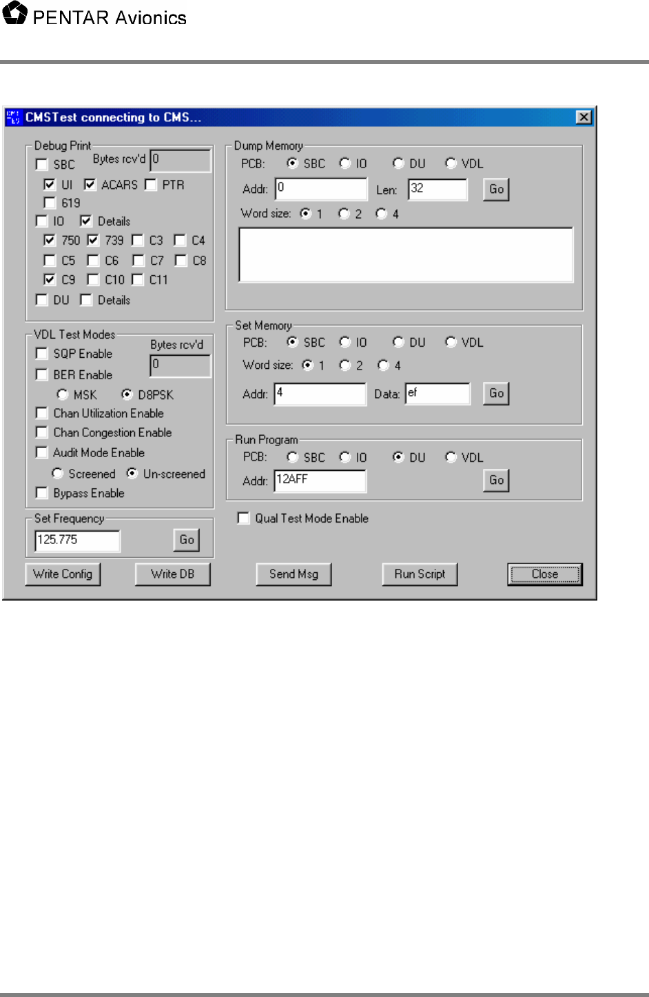
To download the configuration to the CMS1000 you must connect the laptop loader to the CMS1000
Ethernet port. Start CMSTest and wait for the title bar to indicate that “CMSTest is connected to CMS”.
Press the “Write Config” button and select the desired configuration file. The file will be downloaded and
written to the personality module. The CMS1000 will automatically reboot.
5.2 Editing a configuration
On the CMS1000 display select the CONFIG menu. Note that the path to get to the CONFIG menu may
change depending on the user database. In the CONFIG menu select “USER EDIT” to edit the user
fields or “SYS EDIT” to edit the system fields (editing the system fields is NOT recommended for the
user). After modifying any desired fields press the return key or RETURN LSK. The confirmation menu is
displayed. The selection field defaults to YES. Pressing the LSK cycles the selection to NO, to CANCEL,
and back to YES. Pressing the return key or RETURN LSK accepts the selection. If YES is selected the
password menu is displayed next. Type the appropriate password (default is “USER00” for the user
config and “PENTAR” for the system config). Press ENTER to enter the password. The configuration will
be written to the personality module and the CMS1000 will automatically reboot.
5.3 Downloading a database
The database file is a pair of text files that can be modified by any text editor (Windows notepad is a good
choice). The database is a simple, specialized, language for specifying MENUs, variables, ACARS
message contents, etc. The syntax for the database language is in the sections following. It is divided
into two files that we call the CORE and USER databases. The core database is always named
CMS1000_core_db.txt and contains all the CMS system critical definitions of variables, functions, and
ACARS messages and can only be modified by Pentar. It is protected by a special check code that
allows any modifications to be detected by the compiler. If the core database is modified the compiler will
display an error message and refuse to compile the database. The user database is completely defined
by the user. Several of the core functions can be replaced in the user database to customize the
functionality of the CMS as noted in the syntax sections below.
After modifying a database it must be compiled with CMSComp then downloaded with CMSTest on the
laptop loader.
Users Manual
5630-5101-A00 Rev. B 7
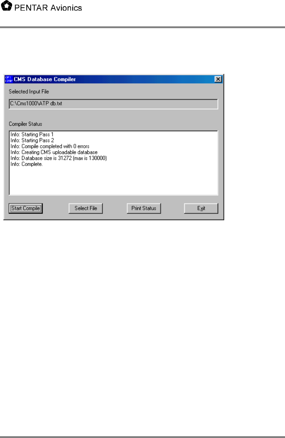
5.3.1 Database Compiler
To compile the database run CMSComp.exe, press the “Select File” button and select the desired user
database file, then press the “Start Compile” button. The compiler will automatically verify integrity of the
core database, compile it then compile the user database. The status and any errors will be displayed in
the “Compiler Status” window. The resulting compiled database will always be saved in
“C:\CMS1000\CMS1000.DB”.
Users Manual
5630-5101-A00 Rev. B 8
To download the database to the CMS1000 you must connect the laptop loader to the CMS1000 Ethernet
port. Start CMSTest and wait for the title bar to indicate that “CMSTest is connected to CMS”. Press the
“Write DB” and the database will be downloaded and written to the personality module. The CMS1000
will automatically reboot.
5.4 The database
The database contains definitions for menus, functions that can be invoked from menus, ACARS
message formats, user variable definitions, and the message loops.
5.4.1 Menu Definitions
The menu definitions consist of:
• The text to place on a screen, its format, and where it is placed. Since the CMS DU emulates a
standard 14 line ARINC 739 display all 12 text lines are used in the database definition. The DU itself
divides it up into two pages (see below).
• The function to perform when a line select key (LSK) is pressed while a particular menu is being
displayed.
Users Manual
5630-5101-A00 Rev. B 9
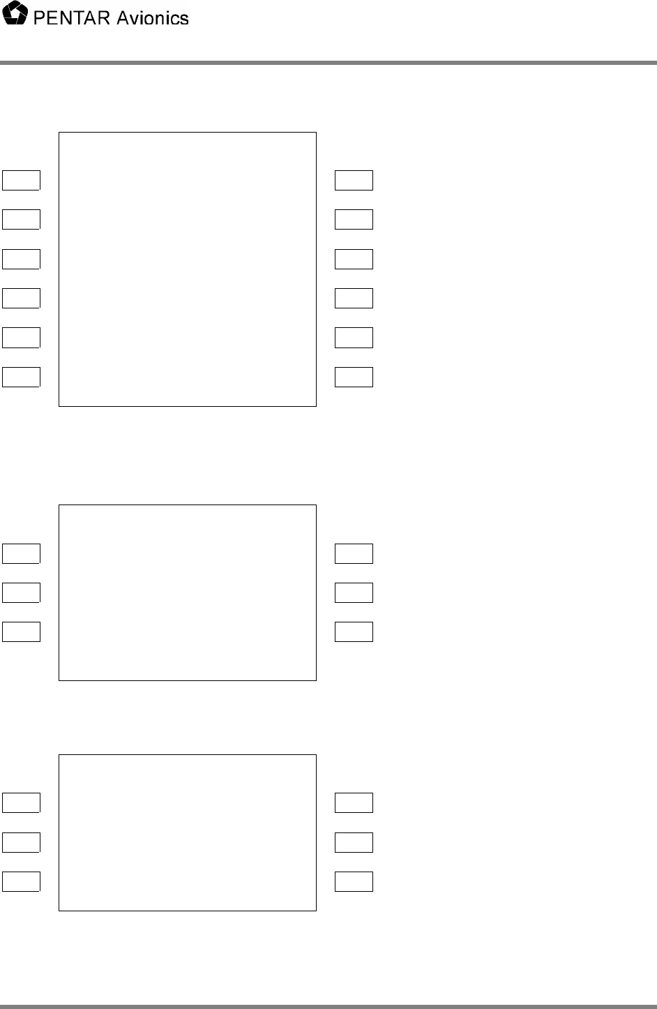
Example:
ACARS MAIN MENU T0
T1
L1 - <PREFLIGHT FLT LOG> - R1 T2
T3
L2 - <ENROUTE MSGS RCVD> - R2 T4
T5
L3 - <POSTFLIGHT REPORTS> - R3 T6
T7
L4 - <UTC TIME REQUESTS> - R4 T8
T9
L5 - <MAINT MENU MISC MENU> - R5 T10
ADVISORY T11
L6 - XXXXXX - R6 T12
SCRATCH PAD
Figure 4.2-1 Example ACARS Main Menu
ACARS MAIN MENU A T0
T1
L1 - <PREFLIGHT FLT LOG> - R1 T2
T3
L2 - <ENROUTE MSGS RCVD> - R2 T4
T5
L3 - <POSTFLIGHT REPORTS> - R3 T6
SCRATCH PAD
A/B NEXT
Figure 4.2-2 Example ACARS Split Main Menu (A screen)
ACARS MAIN MENU B T0
T7
L4 - <UTC TIME REQUESTS> - R4 T8
T9
L5 - <MAINT MENU MISC MENU> - R5 T10
ADVISORY T11
L6 - XXXXXX - R6 T12
A/B NEXT SCRATCH PAD
Figure 4.2-3 Example ACARS Split Main Menu (B screen)

Users Manual
5630-5101-A00 Rev. B 10
This menu could be defined as follows.
MENU= defines the name of the menu function and defaults to the title. The default title defined in the
MENU= command can be overridden using the T0 (T zero) command (see below). A menu name (or
function, send, or variable name) cannot contain spaces, tabs, or commas.
L1 through 6 and R1 through 6 define the functions that the left and right line select keys (LSK) perform
when pressed. In this sample each LSK (except R6) calls a different menu. The name of the menu is
used for the display text unless otherwise specified (see UTC_MENU). The appropriate < or > is
automatically added to the menu name to create the display text. If the LSK calls a function or sends a
message the * is added to the display text. R6 is connected to the ADVISORY variable.
The T11 line creates the title for the ADVISORY variable. Traditionally titles other than the main title are
in the small font hence the lower case “s” in the first character position.
MENU=MAIN_MENU
T0 “ACARS MAIN MENU”
T11 “s ADVISORY”
L1 MENU PREFLIGHT
L2 MENU ENROUTE
L3 MENU POSTFLIGHT
L4 MENU UTC_MENU “UTC TIME”
L5 MENU MAINT MENU
R1 MENU FLT_LOG “FLT LOG”
R2 MENU MSGS_RCVD “MSGS RCVD”
R3 MENU REPORTS
R4 MENU REQUESTS
R5 MENU MISC_MENU “MISC MENU”
R6 VAR ADVISORY
END MENU
Users Manual
5630-5101-A00 Rev. B 11
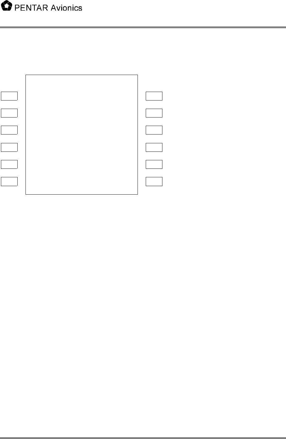
Second Example:
INIT DATA T0
FLT NO DATE T1
L1 - NNNN NN - R1 T2
DEPT DEST T3
L2 - AAAA AAAA - R2 T4
ETD ETE T5
L3 - HHMM HHMM - R3 T6
GW MSG BUFFER T7
L4 - NNNNN [RECEIVE] - R4 T8
T9
L5 - AUTO_INIT* - R5 T10
T11
L6 - <RETURN TOGGLE FN* - R6 T12
SCRATCH PAD
Figure 4.2-2 Example Init Data Menu
The following defines the above menu and functions called from it. In this menu the text fields above the
LSKs are defined by the T1, T3, T5, T7 text commands. Text commands specify the text for whole width
of the display. Text command can contain formatting characters (the lower case “s” selects a small font
here) and variable names. See formal syntax for LSKs.
This example associates the LSKs to variables (VAR command and SELECT command). By default the
current value of the user variable is displayed in the appropriate LSK field in the format defined for that
variable (see User Variable Definitions.) In this example, left line select key 6 (L6) is connected to the
RETURN function that returns to the calling menu. “<RETURN” is displayed in the L6 field. R5 calls a
function named AUTO_INIT. By default the text “AUTO_INIT*” is displayed in the R5 field (it”s a function
hence the * instead of a >). AUTO_INIT contains statements to set the variables used in the display to
the current value of other user variables (presumably variables extracted from 429 or discrete inputs –
see User Variable Definitions) and a constant then redisplays the INIT_DATA menu. (Note: when the
same menu is redisplayed or reselected the data on the menu is updated but the menu is not added
again to the call stack).
The SELECT command displays the current selection of a variable from its selection list (see User
Variable Definitions). It is identified with the “[“ and “]” around the variable contents. Each press of its
LSK selects the next item in the selection list in a circular fashion.
INIT_DATA has 4 pages. The NEXT and PREV commands link the pages together. They are accessed
using the NEXT/PREV LSK key. INIT_DATA_2 shows an example of a text line including a variable to
display and specifying the underline font for the variable contents.
Another way to create multiple page menus is with the PAGES and ITEMS commands. See the example
of the MESSAGE menu below that displays the current ACARS message buffer. The PAGES are set to
zero to tell the CMS to figure out how many pages this message will require based on the number of
ITEMS per page and use that number as the max on the display. The @MSG special function knows
which page it is on to display the appropriate data. MESSAGE also shows an example of the DELETE
command to delete the current ACARS message from the buffer and the PRINT command to print the
contents of the current message when a printer is attached to the CMS.

Users Manual
5630-5101-A00 Rev. B 12
MENU=INIT_DATA
NEXT INIT_DATA_2
PREV INIT_DATA_4
T0 “INIT DATA”
T1 “sFLT NO DATE”
T3 “sDEPT DEST”
T5 “sETD ETE”
T7 “sGW MSG BUFFER”
L1 VAR FLT_NUMBER
L2 VAR DEP_AIRPORT
L3 VAR EST_TIME_DEP
L4 VAR GROSS_WEIGHT
L6 RETURN
R1 VAR DATE
R2 VAR DEST_AIRPORT
R3 VAR EST_TIME_EXIT
R4 SELECT MSG_BUFFER
R5 FUNC AUTO_INIT
R6 FUNC TOGGLE_FLT_NUM “TOGGLE FN”
END MENU
FUNC=AUTO_INIT
SET FLT_NUMBER FROM FLT_NO
SET DEP_AIRPORT FROM DEPARTURE_AP
SET EST_TIME_DEP FROM ETD
SET GROSS_WEIGHT FROM 12345
SET DATE FROM DAY
SET DEST_AIRPORT FROM DESTINATION_AP
SET EST_TIME_EXIT FROM ETE
MENU INIT_DATA
RETURN
END FUNC
MENU=INIT_DATA_2
NEXT INIT_DATA_3
PREV INIT_DATA
T0 “INIT DATA 2”
T2 “ACARS BUFFER=u”, MSG_BUFFER,”u!”
L3 RETURN
END MENU
MENU=INIT_DATA_3
NEXT INIT_DATA_4
PREV INIT_DATA_2
T0 “INIT DATA 3”
L3 RETURN
END MENU
MENU=INIT_DATA_4
NEXT INIT_DATA
PREV INIT_DATA_3
T0 “INIT DATA 4”
L3 RETURN
END MENU

Users Manual
5630-5101-A00 Rev. B 13
MENU=MESSAGE
PAGES 0
ITEMS 9
T0 "s",@MSG(T,0)
T1 @MSG(L,1)
T2 @MSG(L,2)
T3 @MSG(L,3)
T4 @MSG(L,4)
T5 @MSG(L,5)
T6 @MSG(L,6)
T7 @MSG(L,7)
T8 @MSG(L,8)
T9 @MSG(L,9)
L5 DELETE
R5 PRINT
L6 RETURN
END MENU
A note about updating personality module data and the PASSWORD command: When a password is
attached to a menu it is only used in conjunction to updating the personality module. When one or more
variables are modified whose source is the personality module the variables are held in temporary
storage. When returning from the menu that they were modified in the CMS verifies that it is on the
ground (personality module changes are not allowed in air). Then a menu will be displayed confirming
changes to the personality module. The user selects YES or NO and presses RETURN. Finally a
password menu is displayed. The user enters the password then presses the ENTER key (this is
intentionally changed from the RETURN key used to exit other menus). The user is allowed three
attempts to enter a correct password. If the aircraft is in air or the user answers NO to the confirmation or
cannot enter a correct password in three attempts the personality module changes will be discarded and
the original values will be used. Otherwise, the data will be written to the personality module and the
CMS will restart.
5.4.1.1 Formal Syntax
<menu block>: MENU=<menu name>
[<menu command>…]
END MENU
<menu command>: <Pages command> | <Items command> | <Password command> | <text command> |
<LSK command> | <Next command> | <Prev command>
<Pages command>: “PAGES” <max pages>
<max pages>: “0” though “9”
Note: When <max pages> is set to zero the CMS will interrogate the current selected message and
determine how many pages it will use based on the ITEMS value.
<Items command>: “ITEMS” <items per page>
<items per page>: “1” through “9”
<Password command>: “PASSWORD” <variable name>
<Next command>: “NEXT” <menu name>
<Prev command>: “PREV” <menu name>
<text command>: “T”<line number> <text line>
<line number>: “0” through “12”

Users Manual
5630-5101-A00 Rev. B 14
<text line>: <text token>[,<text token>…]
<text token>: <quoted format string> | <variable name> | <special function>
<quoted format string>: “[<string character>…]”
<string character>: <display character> | <format character>
<quoted string>:“””[<display character>…]”””
<display character>: <alpha character> | <digit> | <symbol>
<alpha character>: upper case characters “A” through “Z”
<digit>: “0” through “9”
<symbol>: “!” | “@” | “#” | “$” | “%” | “^” | “&” | “*” | “(“ | “)” | “+” | “-” | “\” | “/” | “.” | “ “
<format character>: “s” | “r” | “u” | “v” | “f”
<variable name>: <alpha character> | <number> [<alpha character> | <number> | “_”…]
<special function>: “MSG(“<msg code>,<msg item>”)”
<msg code>: “T” | “S” | “L”
<msg item>: “1” through “9”
Notes: <text line> and <variable name> are limited to 24 characters
<text line> length is determined by the number of non <format characters> plus the format length of each
<variable name>.
<format character> is defined as follows:
“s” Small font
“r” Regular font
“u” Underline (toggle)
“v” reverse Video (toggle)
“f” Flashing (toggle)
<format characters> apply only to the current <text line>. Default is regular font and no underline, reverse
video, or flashing if no <format character> is specified. Items indicated as “toggle” turn on the format on
the first occurrence and turn it off on the next occurrence.
<msg code> is defined as “T” for the title line of the message, “S” is the status (OLD or NEW) for the
message, and “L” is the line from the message. The title line of a message defaults to the label and the
time it was placed in the buffer. This can be changed using the SEND “HERE” function (see SUND
functions below).
Line select commands (L1 – L6, R1 – R6)
<LSK command>: “L”< LSK number> <command> [<text line>] |
“R”< LSK number> <command> [<text line>]
< LSK number>: “1” through “6”
<command>: “MENU” <menu name> |
“SEND” <send name> |
“FUNC” <func name> |
“VAR” <variable name> |

Users Manual
5630-5101-A00 Rev. B 15
“SELECT” <variable name> |
“RETURN” |
“DELETE” |
“PRINT”
<menu name>: <variable name>
<send name>: <variable name>
<func name>: <variable name>
Note: For Line Select commands the <text line> is used to override the default display text. The default
display text for MENU is the <menu name>, FUNC is <func name>, SEND is “SEND”, RETURN is
“RETURN”, PRINT is “PRINT”, and DELETE is “DELETE”. For the VAR and SELECT commands the
<text line> is ignored since the current value of the variable is always displayed. When <command> is
MENU or RETURN the display text is preceded by the “<“ character for Left LSKs and succeeded by a “>“
character for Right LSKs. For FUNC, SEND, PRINT and DELETE the display text is preceded by the “*”
character for Left LSKs and succeeded by a “*” character for Right LSKs. For SELECT the contents of
the variable is surrounded by square brackets “[“ and “]”. Each press of its LSK selects the next item in
the selection list. No characters are added to the display text for the VAR command.
5.4.2 User Functions
User functions consist of statements to invoke menus (MENU), call other user functions (FUNC), set
values in user variables (SET), send ACARS messages (SEND), and perform simple logic statements (IF,
THEN, ELSE).
For example, if the function TOGGLE_FLT_NUM is invoked by pressing LSK R6 in the INIT_DATA menu
the function might look like:
FUNC=TOGGLE_FLT_NUM
IF (FLT_NUMBER = 86) THEN
SET FLT_NUMBER FROM 68
ELSE
SET FLT_NUMBER FROM 86
END IF
MENU INIT_DATA
RETURN
END FUNC
If the value of FLT_NUMBER is 86 then it is changed to 68 and visa-versa. Then the INIT_DATA menu is
redisplayed.
The IF command can compare a variable to another variable or a constant. It can be followed by AND or
OR followed by another comparison. See MESSAGE_LOOP for additional examples. Parenthesis are
required (see formal syntax). Any number of statements can be between the IF and the ELSE (the IF
block) and the ELSE and the END IF (the ELSE block). The ELSE block is optional. An IF must always
end with END IF. Nested IFs are allowed. Allowed comparison operators are: = (equal), <> (not equal),
<= (less than or equal to), >= (greater than or equal to), > (greater than), or < (less than). Allowed
arithmetic operators are + (add), - (subtract), * (multiply), / (divide). A string concatenation operator & is
also allowed.
Note that parenthesis are important in the database syntax of the IF and the SET statement. In simple
terms, an IF THEN requires an expression that evaluates to a zero or not zero and SET can set a value
FROM an expression. An expression must always be in parenthesis and has the general format of “(X
operator Y)”. For example, the expression could be “(X = Y)” where X is compared to Y. X itself can be
an expression say “(A / B)” so the total expression would be “((A / B) = Y)”. Other examples:

Users Manual
5630-5101-A00 Rev. B 16
• IF ((ALT > 10000) AND (AIRSPEED <150)) THEN
• SET UPDATE_FLAG FROM (GMT_UPDATED AND (FP_UPDATED OR MENU_UPDATED))
• SET GMT FROM FUNC CONVERT_GMT
• SET FORMATTED_GMT FROM ((((GMT_HRS & “:”) & GMT_MIN) & “:”) & GMT_SEC)
Expressions are evaluated left to right with NO operator precedence so use parenthesis to make it
unambiguous.
Note that all variables are global in the CMS and may be defined in either the core or user database.
• The SET command sets the value of a variable. The value can be a variable, a constant, an arbitrary
expression, or the result of a function call. When setting a variable to a constant or another variable
the parenthesis are optional. See formal syntax below.
• The MENU command invokes a menu. The function puts the menu into the display queue and
continues (i.e. does not wait for the menu to be displayed or accept user input).
• The SEND command calls the SEND function. Similar to the MENU it puts the ACARS message in
the transmit queue and continues.
• The FUNC command calls another function. Execution continues after the called function returns.
• The RETURN command exits the function and may return a value.
• The FUNC must always end with END FUNC.
5.4.2.1 Formal Syntax
<func block>: FUNC=<func name>
[<func command>…]
END FUNC
<func command>: <set command> | <menu command> | <if block> |
<send command> | <return> | <func call>
<set command>: “SET” <variable name> “FROM” <data source>
<data source>: <variable name> | <constant> | <expression> | <func call>
< expression >: “(“ <variable name> |
<constant> |
<variable name> <operator> < expression > |
<variable name> <operator> <variable name> |
<variable name> <operator> <constant > |
<expression> <operator> <expression> “)”
<operator>: “+” | “-” | “*” | “/” | “AND” | “OR” | “>“ | “<“ | “<>“ | “=“ | “<=“ | “>=“ | “&”
<menu command>: MENU <menu name>
<send command>: SEND <send name>
<func call>: FUNC <func name>
<return>: RETURN [<variable name>]
<if block>: IF < expression > THEN
[<func command>…]
[ELSE

Users Manual
5630-5101-A00 Rev. B 17
[<func command>…]]
END IF
Note: the compiler will verify that the contents of a <constant> is consistent with format of the associated
variable.
5.4.3 ACARS Message Formats (SEND function)
ACARS messages are defined in a SEND function that allows the user to combine text and the current
value of user variables into a correctly formatted message and transmit it to the ground.
//Create an emergency ACARS message
SEND=EMERGENCY_REPORT_MSG
LABEL “00”
“ 01 HIJACK “,FLIGHT_NO,”/”
SCHEDULE_DATE,” “,DEPARTURE_AP,”/”
DESTINATION_AP,” “,REGISTRATION,CRLF
“/MAL”,NUMBER_OF_MALES
“/FEM”,NUMBER_OF_FEMALES
“/WPN”,WEAPONS_FLAG
“/CPT”,IN_COCKPIT_FLAG
“/TMP”,TEMPERAMENT_FLAG,CRLF
ER_FREE_1,ER_FREE_2,ER_FREE_3
END SEND
The message is created by concatenating all the parts into a long string. The constant text must be in
double quotes. The fields are separated by carriage returns, commas, tabs, or spaces. As many lines
MAY be used as desired and extra spaces or tabs between fields are ignored. A special “variable” is
CRLF that inserts a carriage return/line feed into the message. The LABEL command is required in the
send block. The number of characters and format for variables is defined in the user variable definitions.
In the user database only the following labels are allowed:
• Q7, 5Z, 00, 5D, 5U, 7A, 7B, or RB
There are two special labels, HERE and ETHER (or ETHERNET).
• HERE directs the message directly to the CMS receive buffer and turns on the MSG lamp. This
allows the CMS to send an arbitrary message to the pilots or to reformat a received message to
be more easily read.
• ETHER (or ETHERNET) directs the message to the CMS Ethernet interface. An application with
the ability to receive these messages must be running or the messages will be lost. The Ethernet
application can be running on a Pentar JetLan or similar device. It can operate as a simple flight
data recorder, perform FOQA type flight analysis, store maintenance messages for delivery to the
airline maintenance shop after landing, etc.
A special SEND function name is defined called CURRENT. Putting “SEND CURRENT” in a FUNC will
cause the LSK associated with a SEND in the current menu to be selected. If the current menu has no
SEND defined an error message “NOTHING TO SEND” will be displayed on the scratch line.
5.4.3.1 Formal Syntax
<send block>: SEND=<send name>
LABEL <label code> | “HERE”,<HERE title> | “ETHER” | “ETHERNET”
[<send text>…]

Users Manual
5630-5101-A00 Rev. B 18
END SEND
<label code>: “”“<display character><display character>”””
<HERE title>: <text line>
<send text>: <quoted string> | <variable name> | “CRLF”
5.4.4 Receive ACARS Message (RECV function)
The RECV function allows for automatic processing of received ACARS. Any ACARS message that is
received by the CMS is first compared to the LABEL and (optionally) SUBLABEL for all the defined RECV
functions. If it matches one of them the received text is decoded using the variables defined in the
<RECV text> and the FLAG variable is set to 1. The message is then discarded (i.e. it is not sent to the
received message buffer). A function interested in doing something when the message is received can
watch for the FLAG becoming 1 and perform its special processing. It should then reset the FLAG to
zero. If an incoming ACARS message does not match any RECV functions it is placed in the ACARS
receive buffer and the message lamp is lit. Typical uses for RECV would be to decode GMT uplinks, to
intercept the “Go to voice mode” uplink and respond with an appropriate “Function not supported”
message, to intercept standard ACARS messages and reformat them for easy readability.
When a SUBLABEL is specified, the user can define it as 1, 2, or 3 characters long and specify the
location in the received message to find the sublabel. Sublabel position 1 is the first character after the
STX of the standard ACARS message (see ARINC 618 and 620). The data is decoded by specifying
variables to insert the data into. The number of characters inserted into the variable is determined by the
variable format (see User Variable Definitions below). To skip space you need to insert one or more
dummy variables whose format contains the correct amount of space to skip.
In the following example the GMT uplink is label 51 and contains no sublabel. The body of the message
contains 6 characters HHMMSS and GMT_HRS, GMT_MIN, and GMT_SEC each contain a format of
(ZZ) to obtain 2 characters each. After the message is decoded, GMT_UPDATED is set to 1 and can be
used in a function to note the receipt of the GMT uplink.
//Get the GMT uplink and process the time into the CMS system GMT variables
RECV=GMT_UPLINK
LABEL “51”
FLAG GMT_UPDATED
GMT_HRS, GMT_MIN, GMT_SEC
END RECV
In the following example an RA uplink with sublabel “~5” in position 10 is decoded. Note the use of
DUMMY2 variable (whose format is “(AA)”) to skip the sublabel position when decoding the message.
RECV=DECODE_RA5
LABEL “RA”
SUBLABEL “~5”,10
FLAG RA5_DECODED
FOUR_CHAR_FLIGHT_NO, FIVE_CHAR_VARIABLE, DUMMY2
DEPARTURE_AP, DESTINATION_AP
OTHER_STUFF
END RECV
5.4.4.1 Formal Syntax
<recv block>: RECV=<recv name>

Users Manual
5630-5101-A00 Rev. B 19
LABEL <label code>
[SUBLABEL <sublabel code>,<sublabel pos>]
FLAG <var name>
[<variable name>…]
END RECV
<label code>: “””<display character><display character>”””
<sublabel code>: “”“<display character>[<display character>][<display character>]”””
<sublabel pos>: 1..220
5.4.5 User Variable Definitions
User variables are defined so that the system can allocate appropriate storage, define the
display/conversion format and allowed values. Also the data source (FROM a 429 receiver, a discrete
input, or derived from other variables or constants) and data sink (like a discrete output) are defined.
There are several predefined variables for the system (see the sample compiler source file). The user
variables are defined after them or in the user database file.
The item in parenthesis after a variable name describes the variable’s format and range or selection list.
For formats “A” is any ASCII character, “N” is a number, “S” specifies a signed numeric, “B” is BCD
characters, “Z” specifies leading zeros, “P” is a password (Displays with “*”s). Numeric and character
values are restricted to the field size. A variable’s initial value is the first item in the selection list if it is
included, otherwise it is zero for numeric data and a blank for ASCII/password data.
FROM defines the source of the data. A source beginning with 429R come from the 429 receive ports.
The port number, label value, start and end bit range must be specified. Optionally a slope and offset to
convert the raw value to engineering units is allowed. A source beginning with DI comes from a discrete
input. Only one bit is allowed resulting is a value of zero or one. A source of DO goes to the discrete
output. A zero is written if the value of the variable is zero else a 1 is written. A source of P(n) refers to
the personality module. “n” is the offset in the personality module to read/write the variable. A source of
GPS(n) refers to the n’th of the decoded GPS data. The source can also be a simple expression or a
function call.
VARS
//THE FOLLOWING VARIABLES MUST BE DEFINED FIRST AND IN THIS ORDER
ADVISORY (AAAAAAAA)
AIRCRAFT_7C_ADDR (AAAAAAA) FROM P(232)
AIRCRAFT_ICAO_ADDR (NNNNNNNN) FROM P(240)
FLIGHT_NUMBER (AAAAAA)
CAT_MODE (AAA, "ALL","A","B","A2","B2","2") FROM P(253)
FREQ_MSK_1 (NNN.NNN) FROM P(257)
FREQ_MSK_2 (NNN.NNN) FROM P(265)
FREQ_MSK_3 (NNN.NNN) FROM P(273)
PREKEY_D8PSK (NN) FROM P(324)
TM1_D8PSK (NNN) FROM P(327)
TM2_D8PSK (NNN) FROM P(331)
M1_D8PSK (NNNNN) FROM P(335)
PERSISTANCE_D8PSK (N.NNN) FROM P(341)
IN_AIR (AAA,"GND","AIR")
BUFFER_SELECT (AAAAAAAA,"RECEIVE","TRANSMIT","HISTORY")
DU_CONFIG (N,1,2) FROM P(36)
C1_DRIVER (AAAAAAA,"A750",”A750E”) FROM P(48)

Users Manual
5630-5101-A00 Rev. B 20
C1_ENABLE (A,"Y","N") FROM P(56)
C1_SAL (AAA,"250","251","252","253") FROM P(58)
C3_SAL (AAA) FROM P(92)
C4_DRIVER (AAAAAAA,"NONE") FROM P(99)
//END OF REQUIRED SYSTEM VARIABLES
//User variables...
//Variables retrieved from a 429 port
FLT_NO (NNNNNN) FROM 429R(3 55, 9, 26)
//Range checked value
DAY (NN,1,31) FROM 429R(3 70, 9, 14)
ALT (NNNNN.NN) FROM 429R(3 72, 9, 26, 1.0, 0.0)
LAT (SNNN.NNNN) FROM 429R(3 73, 9, 29, 0.001, 0.0)
LONG (SNNN.NNNN) FROM 429R(3 74, 9, 29, 0.001, 0.0)
UTC (NNNN)
HDG (SNNN.N) FROM 429R(3 76, 9, 24, .01, 0.0)
//BCD data
FUEL_QTY (BBBB) FROM 429R(3 77, 9, 28)
//Variables retrieved from a discrete input
DOORS_CLOSED (N) FROM DI(1)
//Variables output to a discrete output
CHIME (N) FROM DO(1)
//GPS variables
GPS_HRS (ZZ) FROM GPS(1)
GPS_MIN (ZZ) FROM GPS(2)
GPS_SEC (ZZ) FROM GPS(3)
GPS_LAT (SNN.NNNNN) FROM GPS(4)
GPS_LONG (SNNN.NNNNN) FROM GPS(5)
GPS_ALT (NNNNN) FROM GPS(6)
//Variable derived from a function
GPS_GMT (ZZZZZZ) FROM FUNC CONVERT_GPS_GMT
FORMATTED_GMT (AAAAAAAA) FROM FUNC FORMAT_GMT
//Variables for menu display/entry
ALL_DOORS_CLOSED (N)
CHIME_OUT (N)
SCHEDULE_DATE (NN)
REGISTRATION (AAAAAA)
NUMBER_OF_MALES (NN)
NUMBER_OF_FEMALES (NN)
//Selection lists
WEAPONS_FLAG (A,"Y","N")
IN_COCKPIT_FLAG (A,"N","Y")
TEMPERAMENT_FLAG (AAAAAA,"CALM","UNRULY","WILD")
FREE_TEXT1 (AAAAAAAAAAAAAAAAAAAAAAA)
FREE_TEXT2 (AAAAAAAAAAAAAAAAAAAAAAA)
FLT_NUMBER (AAAAAA)
DEPARTURE_AIRPORT (AAA)
DESTINATION_AIRPORT (AAA)
EST_TIME_DEP (NNNN)
OUT_VAR (N)
OFF_VAR (N)

Users Manual
5630-5101-A00 Rev. B 21
TIMER (NNNNN)
MON_TIMER (NNNN)
OOOI_ENABLED (N)
//Constant value
POSITION_TIME (NNNNN) FROM 10
BOARDED_FUEL (NNNNN)
CAPT_FO (A,”C”,”F”)
MONITOR (N,0,1)
END VARS
5.4.5.1 Formal Syntax
VARS
[<variable definition>…]
END VARS
<variable definition>: <variable name> <var format> [“FROM” <source>]
<var format>: “(“<unsigned format> | <alpha format> | <signed format> |
<zero format> | <BCD format> | <password format>
[“,”<range>|<value list>]”)”
<unsigned format>: “N”[“N”…][“.”][“N”…]
<alpha format>: “A”[“A”…]
<BCD format>: “B”[“B”…][“.”][“B”…]
<zero format>: “Z”[“Z”…] //integers only
<signed format>: “S”<unsigned format>|<BCD format>
<password format>: “P”[“P”…]
<source>: <429 input> | <discrete input> | <discrete output> | <personality> |
<GPS input> | <simple expression> | <func call>
<429 input>: “429R(”<429port> <label> <start bit> <end bit>
[<slope> [<offset>]]”)”
<429port>: “1” through “6”
<label>: “000” through “377”
Note: <label> is specified in octal per 429 convention.
<start bit>: “9” through “32”
<end bit>: “9” through “32”
<slope>: <float number>
<offset>: <float number>
<float number>: [“+” | “-“] <digit>[<digit>…] [“.”] [<digit>…] [“E”<digit><digit>]

Users Manual
5630-5101-A00 Rev. B 22
<constant>: <float number> | <quoted string>
<discrete input>: “DI(”<discrete input port>”)”
<discrete input port>: “1” through “8”
<discrete output>: “DO(”<discrete output port>”)”
<discrete output port>: “1” through “4”
<personality>: “P(“<personality address>”)”
<personality address>: “0” through “512”
<range>: <float number>”,”<float number>
<value list>: <constant>”[“,”<constant >…]
<GPS input>: “GPS(“<gps variable>”)”
<GPS variable>: “1” through “99”
The GPS variables are currently defined as:
1. HRS
2. MIN
3. SEC
4. LAT
5. LONG
6. ALT
Using undefined GPS variable will not cause an error but will result in the data value of X’s.
<func call>: “FUNC” <func name>
<simple expression>: <constant> |
<variable name> |
<variable name> <operator> <constant> |
<variable name> <operator> <variable name> |
<constant> <operator> <variable name>
Note: unlike expressions in functions parenthesis are not allowed here and nested expressions are not
allowed. To set the value of a variable to something more complicated than a simple expression define
the expression in a function and set the source to the function.
5.4.6 The Message Loops
The two message loop functions are special functions that perform periodic functions not necessarily
associated with a menu. The loops are executed each second and perform the same commands as in
the FUNC. All the commands of a FUNC are allowed. They must be the first two functions defined. The
first message loop is SYS_MESSAGE_LOOP and is defined in the core database file and is not
modifiable by the user. The second message loop is USER_MESSAGE_LOOP and is normally defined
by the user to handle OOOI messages, etc. An empty USER_MESSAGE_LOOP is defined in the core
database and may be redefined in the user database by creating a FUNC with the same name.
FUNC=USER_MESSAGE_LOOP

Users Manual
5630-5101-A00 Rev. B 23
//The following displays a monitor menu every time the
//timer expires to view contents of variables.
IF ((MONITOR = 1) AND (MON_TIMER >= POSITION_TIME)) THEN
SET MON_TIMER FROM 0
MENU MONITOR_MENU
ELSE
SET MON_TIMER FROM (MON_TIMER+1)
END IF
//DO NOTHING IF OOOI IS NOT ENABLED
IF (OOOI_ENABLED = 0) THEN
RETURN
END IF
//Check for OUT event
IF ((OUT_VAR = 0) AND (ALL_DOORS_CLOSED = 1)) THEN
SET OUT_VAR FROM 1
SEND OUT_MESSAGE
END IF
//Check for OFF event
IF ((OUT_VAR = 1) AND (OFF_VAR = 0) AND (IN_AIR = "AIR")) THEN
SET OFF_VAR FROM 1
SEND OFF_MESSAGE
END IF
//Check for position message time
IF ((OFF_VAR = 1) AND (TIMER >= POSITION_TIME)) THEN
SET TIMER FROM 0
SEND POSITION_MESSAGE
ELSE
SET TIMER FROM (TIMER+1)
END IF
//Check for ON event
IF ((OFF_VAR = 1) AND (IN_AIR = 0)) THEN
SET OFF_VAR FROM 0
SEND ON_MESSAGE
END IF
//Check for IN event
IF ((OFF_VAR = 0) AND (OUT_VAR = 1) AND (ALL_DOORS_CLOSED = 0)) THEN
SET OUT_VAR FROM 0
SEND IN_MESSAGE
END IF
//Test the Chime output once when we climb through 5000 ft
IF ((ALT > 5000) AND (CHIME_OUT = 0)) THEN
SET CHIME FROM 1
SET ADVISORY FROM "*CHIME*"
SET CHIME_OUT FROM 1
END IF
//Reset the Chime test when descending below 5000 feet
IF ((ALT < 5000) AND (CHIME_OUT = 1)) THEN

Users Manual
5630-5101-A00 Rev. B 24
SET CHIME FROM 0
SET ADVISORY FROM " "
SET CHIME_OUT FROM 0
END IF
END FUNC
5.4.7 The User Function Keys Functions
The user function keys on the CMS-1000 keyboard are handled by special functions. For example, when
the MSG key is pressed the function USER_MSG is called. If the shift light is on the function
SHIFT_MSG is called. Similarly, USER or SHIFT functions are defined for READ, SEND, EMRG, and
USER keys. Any of the USER or SHIFT functions may be replaced in the user database simply by
defining a function with the same name. A message will be displayed by the CMS compiler noting the
“Overrride” but this is not considered an error.
Default function for each user function is:
1. MSG: Displays the Receive/Transmit/History/HP Xmit buffers
2. READ: Displays “TO BE ADDED BY USER”
3. SEND: Send current message if current menu has SEND defined else displays a warning.
4. EMRG: Displays “TO BE ADDED BY USER”
5. USER: Displays “TO BE ADDED BY USER”
Default functions for each shifted user function is:
1. MSG: Displays “TO BE ADDED BY USER”
2. READ: Displays “TO BE ADDED BY USER”
3. SEND: Displays “TO BE ADDED BY USER”
4. EMRG: Displays “TO BE ADDED BY USER”
5. USER: Print the current ACARS message if displayed else print current menu
The Core CMS database defines the function key functions as:
FUNC=USER_MSG
MENU USER_MSG
RETURN
END FUNC
FUNC=USER_READ
SET TITLE FROM "USER READ"
MENU TO_BE_ADDED
RETURN
END FUNC
FUNC=USER_SEND
SEND CURRENT
RETURN
END FUNC
FUNC=USER_EMRG

Users Manual
5630-5101-A00 Rev. B 25
SET TITLE FROM "USER EMRG"
MENU TO_BE_ADDED
RETURN
END FUNC
FUNC=USER_USER
SET TITLE FROM "USER USER"
MENU TO_BE_ADDED
RETURN
END FUNC
//SHIFTED USER KEYS
FUNC=SHFT_MSG
SET TITLE FROM "SHIFT MSG"
MENU TO_BE_ADDED
RETURN
END FUNC
FUNC=SHFT_READ
SET TITLE FROM "SHIFT READ"
MENU TO_BE_ADDED
RETURN
END FUNC
FUNC=SHFT_SEND
SET TITLE FROM "SHIFT SEND"
MENU TO_BE_ADDED
RETURN
END FUNC
FUNC=SHFT_EMRG
SET TITLE FROM "SHIFT EMRG"
MENU TO_BE_ADDED
RETURN
END FUNC
FUNC=SHFT_USER
//Do a screen print if not in the MSG menu
//else prints the current ACARS message
PRINT
RETURN
END FUNC
MENU=USER_MSG
PAGES 9
ITEMS 5
T0 "ACARS ",BUFFER_SELECT
L1 MENU MESSAGE @MSG(T,1)," ",@MSG(S,1)
L2 MENU MESSAGE @MSG(T,2)," ",@MSG(S,2)
L3 MENU MESSAGE @MSG(T,3)," ",@MSG(S,3)
L4 MENU MESSAGE @MSG(T,4)," ",@MSG(S,4)
L5 MENU MESSAGE @MSG(T,5)," ",@MSG(S,5)
L6 RETURN
R6 SELECT BUFFER_SELECT
END MENU

Users Manual
5630-5101-A00 Rev. B 26
MENU=TO_BE_ADDED
T0 " ",TITLE
T4 " TO BE ADDED BY USER"
END MENU
MENU=MESSAGE
PAGES 0
ITEMS 9
T0 "s",@MSG(T,0)
T1 @MSG(L,1)
T2 @MSG(L,2)
T3 @MSG(L,3)
T4 @MSG(L,4)
T5 @MSG(L,5)
T6 @MSG(L,6)
T7 @MSG(L,7)
T8 @MSG(L,8)
T9 @MSG(L,9)
L5 DELETE
R5 PRINT
L6 RETURN
END MENU
Users Manual
5630-5101-A00 Rev. B 27
6 Operating the CMS-1000
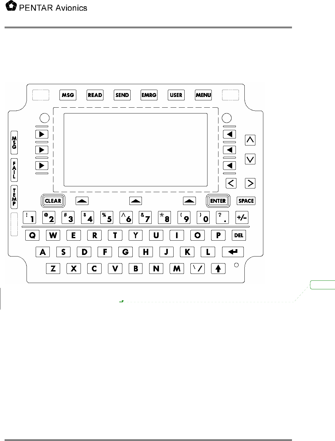
Use the following figure as a guide for the subsection below.
Figure 6-1: Front Panel Assembly
6.1 User Function Keys
The user function keys (with the exception of the MENU key) are user configurable by the user through
the user database. Default functionality is provided for some of the keys. Function of each key is
dependant on the state of the shift key.
Default function for each non shifted user function is:
• MSG: Displays the Receive/Transmit/History/HP Xmit buffer
• READ: Displays “TO BE ADDED BY USER”
• SEND: Send current message if current menu has SEND defined else displays a warning.
• EMRG: Displays “TO BE ADDED BY USER”
• USER: Displays “TO BE ADDED BY USER”
Default functions for each shifted user function is:
• MSG: Displays “TO BE ADDED BY USER”
Deleted:

Users Manual
5630-5101-A00 Rev. B 28
• READ: Displays “TO BE ADDED BY USER”
• SEND: Displays “TO BE ADDED BY USER”
• EMRG: Displays “TO BE ADDED BY USER”
• USER: Print the current ACARS message if displayed else print current menu
Pressing the MENU user key selects the MCDU MAIN MENU where any additional devices using the
CMS1000 as an MCDU can be selected. Normally this only displays <ACARS for the CMS1000 ACARS
functionality. Pressing this button while an ACARS menu is displayed will display the main menu with
<ACARS highlighted as active. Pressing ACARS LSK will return to the current ACARS menu.
6.2 Line Select Keys
There are 3 Line Select Keys (LSKs) on the left and right sides of the display and 3 below the display.
The functions of the left and right LSKs are determined by the menu being displayed (see below). The
function of the 3 lower LSKs are:
1. The leftmost lower LSK is the A/B select. The display operates as a 14 line ARINC 739 display using
a 9 line display to show the information in two parts called the A and B screens. The A screen puts
the MCDU title line on line 1, MCDU lines 2 through 7 on display lines 2 through 7, and the MCDU
scratch line (line 14) on line 8. The B screen puts the MCDU title line on line 1, MCDU lines 8 through
13 on display lines 2 through 7, and the MCDU scratch line (line 14) on line 8. When there is any
text from MCDU line 8 through 13 on the B screen the text above this LSK will read “A/B” and the
rightmost character of display line 1 will show the current screen (either A or B). This LSK will then
toggle between A and B. If this is no text on the B screen the LSK is ignored and the text above the
key is blank.
2. The center bottom LSK is below the Advisory field. It’s function changes depending of the content of
the advisory field.
3. The rightmost bottom LSK is the NEXT/PREV page key. When the shift light is off this is NEXT and
when the shift light is on this is the PREV key. When a menu contains multiple pages the right end of
line 1 (next to the A/B character) displays “n/m” where “n” is the current page and “m” is the total
number of pages. Pressing NEXT increments the current page and pressing PREV decrements it. If
the menu contains only 1 page pressing this LSK will cause the data on the display to be refreshed.
The three left and right LSKs map to the 6 MCDU left and right LSKs. When the A screen is displayed
they map to MCDU LSKs 1 through 3 and when the B screen is displayed they map to MCDU LSKs 4
through 6. The character on the display closest to the LSK determines the function the LSK will perform.
1. “<” or “>” indicates another menu will be displayed.
2. “*” indicates a function will be called or a message will be sent.
3. “[“ and “]” indicates a selection field and each press of the LSK will select the next item in the
selection list.
4. Any other characters normally indicate a variable field for data entry. Pressing the LSK while the
scratch line is blank will cause the current contents of the LSK variable to be copied to the scratch
line for editing. Pressing the LSK when there is data on the scratch line causes the contents of the
scratch line to be copied to the LSK field. The data is verified before it is inserted and an error
message is display for any problems.
5. Text can also be displayed on a line next to an LSK and the LSK will have no defined function. In this
case, pressing the LSK will result in a warning on the scratch line.

Users Manual
5630-5101-A00 Rev. B 29
6.3 The Arrow Keys
The function of the up (^), down (v), left (<), and right (>) arrow keys changes depending on the
circumstances:
1. Normal operation. Shift is off, no data on the scratch line. Up and down move through multiple page
menus ½ a screen at a time. Left is the equivalent of the Return key and right is ignored.
2. Edit mode. Shift is off, there is data on the scratch line. Up and down have the same function as
normal operation. Left and right move the cursor (an underscore) on the scratch line.
3. Dimming mode. Shift is on. The up and down keys adjust the brightness of the display. Left and
right function is the same as normal or edit.
6.4 The CLEAR key
1. If a message is displayed on the scratch line it clears the message and restores the text that was on
the line.
2. If in edit mode it performs a backspace delete function.
3. If held for more than 1 second it clears the scratch line.
6.5 The ENTER key.
1. When data has been copied to the scratch line by pressing the associated LSK, pressing ENTER
stores the edited data to the original LSK field.
2. When entering a password the ENTER key enters and checks the password.
6.6 The DEL key.
The DEL key deletes the character under the cursor.
6.7 The Return Key.
The Return key returns to the previous menu if there is one. If there is no previous menu it is ignored.
6.8 The +/- key.
This key displays a minus in the scratch pad on the first press and will toggle to + with a second press. It
does not change based on the shift key.
6.9 The Shift Key
The shift key operates as a shift lock key. Pressing it toggles the shifted/not shifted lamp (lamp is on
when shifted). Do not hold down the shift key to produce a symbol from the numeric keys. Simply press
shift once to turn on the lamp then press the numeric key to get the desired symbol. Press shift again to
turn it off.
6.10 Typing Keys.
The remaining keys are arranged like a standard QWERTY keyboard and perform the expected
functions. All alphabetic characters are always upper case so they do not respond to the shift key.

Users Manual
5630-5101-A00 Rev. B 30
6.11 System Reset
A manual reset of the CMS1000 can be commanded by simultaneously holding down “Z”, “7” and “/” for 2
seconds. The display changes to inform of impending reset. If held for less than 2 seconds the original
display is restored.
6.12 MSG Lamp
The MSG lamp illuminates when there is at least one unread message in the ACARS receive buffer. The
user can press the MSG user function key to display the ACARS receive buffer. Once the message has
been viewed the light will be extinguished. The ACARS receive buffer can contain 45 messages
maximum. If more than 45 are received the oldest message will be lost whether it was read or not. When
the receive buffer is more than 80% full the MSG lamp will flash. When a message is bumped out of the
receive buffer the advisory display will display “RCV FULL”.
6.13 FAIL Lamp
The FAIL lamp is illuminated when a failure is detected in the CMS. The CMS will perform an automatic
reset to clear the problem. If the problem cannot be cleared the FAIL lamp will stay on and the CMS1000
is considered failed and should be serviced.
6.14 TEMP Lamp
The TEMP lamp will illuminate when the temperature inside the CMS1000 is too cold or too hot to
function. The CMS1000 will stay in reset until the condition clears.

Users Manual
5630-5101-A00 Rev. B 31
7 Maintaining the CMS-1000
The CMS-1000 requires no scheduled maintenance. Following are details associated with the equipment
limitations of the CMS-1000, expected modes of failure, and repair/troubleshooting information.
7.1 Equipment Limitations
7.1.1 Liquid Spills
The CMS-1000 keyboard design incorporates a silicon pad on top of dome switches. The silicon pad
greatly reduces the possibility of liquid ingress, but is not completely water tight. Spill testing has been
performed on the CMS-1000 front panel assembly, and a reasonable amount of exposure to coffee spills
should not cause a CMS-1000 failure. It is expected that if a liquid spill onto the front panel assembly
occurs, that the liquid is wiped off the unit in a timely fashion.
7.1.2 Temperature Extremes
The CMS-1000 is qualified to the temperature/altitude requirements of RTCA DO-160D, category A1. It is
robust at temperatures ranging from –15 °C to 55 °C. The CMS-1000 incorporates an internal
temperature sensing circuit that turns the CMS-1000 off if internal temperatures get too high or too low. It
is verified during qualification testing that the unit will not shut off (as a result of this circuit) if the ambient
temperature is between –15 °C and 55 °C. It is noted that direct sunlight exposure might cause the
ambient temperature at the surface to the front panel to exceed 55 °C. If it is expected that the unit has
shut down because it has been exposed to too high of a temperature due to direct sunlight, the unit
should be shaded and allowed to cool. The CMS-1000 will automatically restart when the internal
temperature is back with limits. The same scenario is true if the ambient temperature is very cold (< -
15°C). The unit will again automatically start when internal temperatures are within the RTCA DO-160D
specified temperature range.
7.1.3 Power and Ground
The CMS-1000 expects aircraft 28 Vdc power and ground per RTCA DO-160D, section 16 category Z. If
the power input is mis-wired (i.e. 28 Vdc is connected to the unit’s ground and the unit’s 28 Vdc input is
connected to ground) no current will flow and the unit will not operate (the unit has an internal reverse
polarity diode). If the 115 Vrms, 400 Hz power is connected to the unit, the unit will be damaged. If
properly wired, the unit can survive 28 Vdc voltage surges of up to 80 Vdc for as long as 100 msecs.
7.1.4 Signal Connections
The digital connections (ARINC429, IEEERS232, IEEERS422 and Ethernet), are rather robust. If the
inputs are miswired (i.e. transmit+ to receive-, or transmit+ to transmit+, or transmit+ to transmit-) no
damage will occur, but, the bus communications will not work. If the connections are grounded (in any
permutation) no damage will occur, but of course the communications will not work. If 28 Vdc power is
connected, there is a possibility of damage, but, it may take a long time for the damage to occur. If 115
Vrms 400 Hz is connected, damage will occur.
7.1.5 Shields
Shield should be grounded at both ends of the cable. If this is not feasible, the end of the cable that is the
source of the signal should be grounded. Shield terminations should be made as short as possible and
either connected to the cable’s connector shell or to a ground pin in the connector.

Users Manual
5630-5101-A00 Rev. B 32
7.2 Expected Modes of Failure
The CMS-1000 uses robust components, most of which dissipate little heat. The major, expected
sources of failure are associated with those components that dissipate significant heat, and the front
panel assembly component.
The components that dissipate significant heat are located on two internal printed circuit assemblies
(PCA), the VHF Data Link (VDL) PCA, and the Display Unit/Power Supply (DU/PS) PCA.
The VDL PCA is the assembly that transmits and receives radio frequency energy via the unit’s RF
antenna. When receiving, the VDL dissipates little heat. When transmitting, the VDL can dissipate over
60 watts of energy during the transmission (it should be noted that the maximum duty cycle for RF
transmission is 20% and the nominal duty cycle is much less than 20%). In the transmit mode, the major
components being stressed on the VDL are the PolyFET transistors. If these should fail, the unit will be in
a NO COMM (no communication) condition and will not exit this status.
The DU/PS contains the unit’s power supply that derives regulated 28 Vdc for the VDL transceiver and
front panel display, and regulated +12 Vdc, 6.5 Vdc, and 3.3 Vdc for the rest of the unit’s internal circuitry.
The components that dissipate the most heat in the power supply are the transformer, the switching FETs
and the switching diodes. Failure of these components will most likely result in a completely inoperable
unit.
The front panel assembly components are exposed to humans. Experience with similar devices has
shown the most likely modes of failure for this unit will be associated with front panel assembly buttons.
Dependent upon where in the cockpit the unit is installed, it may be exposed to maintenance personnel
stepping on the unit, spilling large amounts of liquid, and/or dropping a solid object from some distance on
the unit’s display. Care should be taken when working around these cockpit mounted units. Users will
probably notice failures of this type when they depress a button and nothing happens, or they have to
depress the button several times to get a response, or when some of the display’s pixels do not
illuminate. Under proper care of the front panel, the expected mean-time-between-failure (MTBF) of the
CMS-1000 exceeds 20,000 operating hours.
7.3 Repair and Troubleshooting Information
The CMS-1000 is a line replaceable unit (LRU). If the unit needs repair, the unit should be removed from
the cockpit and either shipped to a repair depot or the manufacturer. A replacement unit, when installed
will automatically program itself to behave in the same manner as the removed unit by reading the
personality module configuration at startup.
As with any digital processing unit, glitches in operation can occur. If a unit’s operation appears faulty,
the user should first perform a system reset (this is accomplished be simultaneously depressing the unit’s
“Z”, “7”, and “/” keys and holding for about 2 seconds. If the unit’s operation returns to normal, the
problem was probably a glitch. If system resets become troublesome, then there are two probable
reasons; 1. The system installation is faulty, or, 2. The unit is faulty. It is obviously easier to remove and
replace the unit than to troubleshoot the system installation. The user should track (by aircraft tail
number) how many removals per time occur. If one airplane has a much higher removal rate, then it is
probable that there is a system installation problem. Another indication of a system installation problem is
if there is a high incidence of no fault founds when the return unit is tested.
The rate of removal of units must be acceptable to the user. The manufacturer will work with the user to
support system installation troubleshooting (if desired) and/or to determine if there are problems
associated with either the unit’s design or manufacturing processes.
Once removed the unit should first undergo a manufacturer’s functional acceptance test. If the unit
passes, the troubleshooter should try to obtain information from the user about the conditions that existed
when the unit failure was detected and try to emulate these conditions, and perform testing in these
conditions. If no failure is yet found, the unit should be exposed to temperature extremes and tested. It
is possible that a failure on a unit, no matter how hard a troubleshooter tries, can be repeated. In this

Users Manual
5630-5101-A00 Rev. B 33
case, the unit is returned with a no fault found corrective action. Such events should cause the user to
suspect potential systemic problems.
If the functional acceptance test indicates that the unit is failed, the unit’s cards are removed, one at a
time from the unit and tested on a card level tester. There are four cards that are easily removable from
the unit (the Single Board Computer Card (SBC), the DU/PS card, the VDL card and the Input/Output (IO)
card). These four cards contain almost all of the unit’s capability. Each of these cards is easily tested on
the CMS-1000 card level tester. If every card in a failed unit operates properly on the card level tester,
the failure is in the chassis assembly. The chassis assembly contains the front panel assembly, the
motherboard assembly and the connector board assembly.
Once the failure is isolated to a removed card assembly (or assemblies) or to the chassis assembly, the
at fault assembly should be either discarded or sent to the manufacturer. It is not cost effective to
troubleshoot assemblies to the component level.
Users Manual
5630-5101-A00 Rev. B A-1
APPENDIX A: CMS-1000 Rear Connector Pin
Assignments
11 Pin Military Circular Connections
Signal Name Description Pin(s)
+28VDC_IN Unit' Input Power A,L
+28V_RTN Input Power Return B
PERSONALITY_CLK Personality Module Connection C
PERSONALITY_DATA Personality Module Connection D
+3.3V Personality Module Connection E
GND Personality Module Connection Ground F
DIMMER_5VDC Cockpit Dimming Input G
DIMMER_COM Cockpit Dimming Input H
CGND Chassis Ground J
61 Pin Military Connections
Signal Name Description Pin(s)
GND Ground A,F,N,a,i,p,
s,x,z,GG,
KK,
429_1_DU_R+_I0_T+ 429 Transmit +, Channel 1 AA
E3_SBC_T+ Ethernet Transmit + B
RS232_1_IO_T RS232 Transmit Channel 1 b
429_1_DU_R-_I0_T- 429 Transmit -, Channel 1 BB
E3_SBC_T- Ethernet Transmit - C
RS232_1_IO_R RS232 Receive Channel 1 c
429_1_DU_T+_I0_R+ 429 Receive + Channel 1 CC
E3_SBC_R+ Ethernet Receive + D
RS232_2_IO_T RS232 Transmit Channel 2 d
429_1_DU_T-_I0_R- 429 Receive - Channel 1 DD
E3_SBC_R- Ethernet Receive - E
RS232_2_IO_R RS232 Receive Channel 2 e
429_R2+ 429 Receive + Channel 2 EE
NOT CONNECTED Not Used f
429_R2- 429 Receive - Channel 2 FF
DISCRETE_OUT1 Output Discrete 1 (28 V Source or Sink 1 amp) G
DISCRETE7_OUT_IN Configurable Discrete 7 (input or output) g
DISCRETE_OUT2 Output Discrete 2 (28 V Source or Sink 1 amp) H
DISCRETE8_OUT_IN Configurable Discrete 8 (input or output) h
TL_MODEM+ Not Used (for future Modem use) HH
DISCRETE_IN1 Input Discrete 1 (Open or Ground) j

Users Manual
5630-5101-A00 Rev. B A-2
61 Pin Military Connections
Signal Name Description Pin(s)
DISCRETE_OUT3 Output Discrete 3 (28 V Source or Sink 1 amp) J
TL_MODEM- Not Used (for future Modem use) JJ
DISCRETE_IN2 Input Discrete 2 (Open or Ground) k
DISCRETE_OUT4 Output Discrete 4 (28 V Source or Sink 1 amp) K
DISCRETE5_OUT_IN Configurable Discrete 5 (input or output) L
SPARE1 Not used LL
DISCRETE6_OUT_IN Configurable Discrete 6 (input or output) M
PIN_1_R_1 RS422 Termination Resistor m
SPARE2 Not used MM
DISCRETE_IN4 Input Discrete 4 (Open or Ground) n
SPARE3 Not Used NN
429_T2+ 429 Transmit + Channel 2 P
SPARE4 Not Used PP
AUDIO TX Not Used (for future use) q
429_T2- 429 Transmit - Channel 2 R
AUDIO RX Not Used (for future use) r
429_R3+ 429 Receive + Channel 3 S
429_R3- 429 Receive - Channel 3 T
RS422_#1_TX+ RS422 Transmit + t
429_R4+ 429 Receive + Channel 4 U
RS422_#1_TX- RS422 Transmit - u
429_R4- 429 Receive - Channel 4 V
RS422_#1_RX+ RS422 Receive + v
429_R5+ 429 Receive + Channel 5 W
RS422_#1_RX- RS422 Receive - w
429_R5- 429 Receive - Channel 5 X
429_R6+ 429 Receive + Channel 6 Y
DISCRETE_IN3 Input Discrete 3 (Open or Ground) y
429_R6- 429 Receive - Channel 6 Z