Spectralux 14114 Dlink+ w/CPDLC. All-in-one data communications, CPDLC and ACARS in a single LRU User Manual 1
Spectralux Corporation Dlink+ w/CPDLC. All-in-one data communications, CPDLC and ACARS in a single LRU Users Manual 1
Contents
- 1. Installation Manual
- 2. Users Manual 1
- 3. Users Manual 2
- 4. Users Manual
Users Manual 1
Dlink+CPDLC Users Guide
Document Number: UG-14114 Rev. - Page 1 of 201
Dlink+CPDLC Users Guide
SLC Doc Number UG-14114
Revision -
12335 134th Court NE
Redmond, WA 98052
USA
Tel: (425) 285-3000
Fax: (425) 285-4200
Email: info@spectralux.com
RESTRICTION ON USE, PUBLICATION, OR DISCLOSURE OF PROPRIETARY INFORMATION
This document contains information proprietary to Spectralux Corporation, or to a third party to which Spectralux Corporation may
have a legal obligation to protect such information from unauthorized disclosure, use, or duplication. Any disclosure, use, or
duplication of this document or of any of the information contained herein for other than the specific purpose for which it was
disclosed is expressly prohibited, except as Spectralux Corporation may otherwise agree in writing.
Preparer: Paul Newby 2011.12.31
Engineer: Paul Newby 2011.12.31
Program Manager: Robert W. Bernstein 2011.12.31
Quality Assurance David Cierebiej 2011.12.24

Dlink+CPDLC Users Guide
Document Number: UG-14114 Rev. - Page 2 of 201
CHANGE RECORD
Paragraph Description Of Change Approval/
Date
Revision
All Initial release Paul Newby
12/20/2011
-
SVN
21123

Dlink+CPDLC Users Guide
Document Number: UG-14114 Rev. - Page 3 of 201
Table of Contents
Dlink+CPDLC Users Guide ......................................................................................................................... 1
SLC Doc Number UG-14114 ....................................................................................................................... 1
Revision - ..................................................................................................................................................... 1
CHANGE RECORD ...................................................................................................................................... 2
1Introduction .......................................................................................................................................... 7
1.1Using the Dlink+ w/CPDLC ........................................................................................................... 8
1.1.1Basic User Interface ................................................................................................................. 9
1.1.2Keyboard ................................................................................................................................... 9
1.1.3Advisories ................................................................................................................................ 11
2Menu Page Tree ................................................................................................................................. 13
2.1Menu Parameter Description ...................................................................................................... 14
3Common Menus ................................................................................................................................. 15
3.1Splash Screen ............................................................................................................................. 15
3.2Main Menu ................................................................................................................................... 16
3.3Main – Flight Information Menu ................................................................................................... 17
3.4Main – Maintenance Menu .......................................................................................................... 18
3.4.1Maintenance – Monitor Menu Page 1 ..................................................................................... 19
3.4.2Maintenance – Monitor Menu Page 2 ..................................................................................... 21
3.4.3Maintenance – System Control Messages Menu ................................................................... 22
3.4.4Maintenance – Configuration Maintenance Menu .................................................................. 23
3.4.5Maintenance - Set UTC Menu ................................................................................................. 24
3.4.6Maintenance – Fail Status Menu............................................................................................. 25
3.5Configuration Maintenance Menu ............................................................................................... 26
3.5.1Configuration Maintenance – Password Menu ....................................................................... 26
3.5.2Configuration Maintenance – User Edit Menu ........................................................................ 27
3.5.3Configuration Maintenance – System Edit Menu .................................................................... 27
3.5.4Configuration Maintenance – Software Versions Menu .......................................................... 27
3.6User Edit Menu ............................................................................................................................ 28
3.6.1User Edit – Edit Configuration Menu Page 1 .......................................................................... 28
3.6.2User Edit – Edit Configuration Menu Page 2 .......................................................................... 29
3.6.3User Edit – Edit Configuration Menu Page 3 .......................................................................... 30
3.6.4User Edit – Edit Configuration Menu Page 4 .......................................................................... 32
3.6.5User Edit – Edit Configuration Menu Page 5 .......................................................................... 33
3.7User Edit – Addresses Configuration Menu ................................................................................ 34
3.8User Edit – User Defined Uplinks Menu ..................................................................................... 35
3.8.1User Edit – Uplink Format Menu Page 1 ................................................................................ 35
3.8.2User Edit – Uplink Format Menu Page 2 ................................................................................ 37
3.8.3User Edit – Uplink Format Menu Page 3 ................................................................................ 39

Dlink+CPDLC Users Guide
Document Number: UG-14114 Rev. - Page 4 of 201
3.8.4User Edit – Uplink Format Menu Page 4 ................................................................................ 41
3.9User Event – User Defined Events Menu ................................................................................... 42
3.10User Edit – User Defined Messages Menu ................................................................................. 44
3.10.1User Edit – User Defined Message Edit Menu Page 1 ....................................................... 44
3.10.2User Edit – User Defined Message Edit Menu Page 2 ....................................................... 45
3.10.3Definition of Optional Data in User Defined Messages ....................................................... 50
3.11User Edit – Software Versions Menu .......................................................................................... 54
3.11.1User Edit – Software Versions Menu Page 1 ...................................................................... 54
3.11.2User Edit – Software Versions Menu Page 2 ...................................................................... 55
3.12System Edit Menu ....................................................................................................................... 56
3.12.1System Edit – System Configuration Menu Page 1 ............................................................ 56
3.12.2System Edit – System Configuration Menu Page 2 ............................................................ 57
3.12.3System Edit – System Configuration Menu Page 3 ............................................................ 58
3.12.4System Edit – System Configuration Menu Page 4 ............................................................ 59
3.12.5System Edit – System Configuration Menu Page 5 ............................................................ 60
3.12.6System Edit – System Configuration Menu Page 6 ............................................................ 61
3.12.7System Edit – System Configuration Menu Page 7 ............................................................ 62
3.12.8System Edit – System Configuration Menu Page 8 ............................................................ 63
3.12.9System Edit – System Recall Information Menu ................................................................. 64
3.12.10System Edit – Analog Input Discrete Configuration Menu .................................................. 65
3.12.11System Edit – Digital Input Discrete Configuration Menu ................................................... 66
3.12.12System Edit – Arinc 429 Input Configuration Menu ............................................................ 67
3.12.13System Edit – Output Configuration Menu .......................................................................... 68
4ACARS Menus .................................................................................................................................... 69
4.1ACARS Index Menu .................................................................................................................... 69
4.1.1ACARS Index – Service Messages Menu .............................................................................. 70
4.1.2ACARS Index – ATS Requests Menu ..................................................................................... 71
4.1.3ACARS Index – Message Log Menu ...................................................................................... 72
4.1.4ACARS Index – System Control Messages Menu .................................................................. 74
4.1.5ACARS Index – Station Table POA Stations Menu ................................................................ 75
4.1.6ACARS Index – Station Table AOA Stations Menu ................................................................ 76
4.1.7ACARS Index – Flight Information Menu ................................................................................ 77
4.2ACARS Service Messages Menus.............................................................................................. 78
4.2.1ACARS Service Messages – Weather Request Menu ........................................................... 78
4.2.2ACARS Service Messages – Estimated Time of Arrival Report Menu ................................... 79
4.2.3ACARS Service Messages – Diversion Report Menu ............................................................ 80
4.2.4ACARS Service Messages – Position Report Menu Page 1 .................................................. 81
4.2.5ACARS Service Messages – Position Report Menu Page 2 .................................................. 82
4.2.6ACARS Service Messages – Estimated Time of Arrival Revision Menu ................................ 83
4.2.7ACARS Service Messages – Engine Data Menu ................................................................... 84

Dlink+CPDLC Users Guide
Document Number: UG-14114 Rev. - Page 5 of 201
4.2.8ACARS Service Messages – User Messages Menu .............................................................. 85
4.2.9ACARS Service Messages – Aircrew Miscellaneous Message Menu .................................... 86
4.2.10ACARS Service Messages – Service Message Setup Menu ............................................. 87
4.2.11ACARS Service Messages – IATA Report Setup Menu Page 1 ........................................ 88
4.2.12ACARS Service Messages – IATA Report Setup Menu Page 2 ........................................ 89
4.2.13ACARS Service Messages – ICAO Report Setup Menu .................................................... 90
4.3ATS Requests Menu ................................................................................................................... 91
4.3.1ATS Request – ATIS Report Request Menu .......................................................................... 92
4.3.2ATS Request – Clearance Request Menu .............................................................................. 93
4.3.3ATS Request – Terminal Weather Information for Pilots Request Menu ............................... 98
4.3.4ATS Request – ATS Free Text Message Menu ...................................................................... 99
4.4System Control Messages Menu .............................................................................................. 100
4.4.1System Control Messages – AVLC Ping Test Menu ............................................................ 101
4.4.2System Control Messages – ACARS Ping Test Menu ......................................................... 102
5ACARS Messages ............................................................................................................................ 103
5.1ARINC 618 Formatted Messages ............................................................................................. 103
5.2ARINC 622 Formatted Messages ............................................................................................. 104
6ACARS Operation ............................................................................................................................ 105
6.1Start up ...................................................................................................................................... 105
6.1.1Entering the Flight Number ................................................................................................... 105
6.1.2Entering Origin and Destination Stations .............................................................................. 105
6.2Sending a Message .................................................................................................................. 105
6.2.1Requirements for Sending a Message .................................................................................. 105
6.3Reading Received Messages ................................................................................................... 105
7CPDLC Operation............................................................................................................................. 106
7.1CPDLC Menus .......................................................................................................................... 106
7.1.1CPDLC – Index Menu ........................................................................................................... 106
7.1.2CPDLC – Free Text Menu ..................................................................................................... 108
7.1.3CPDLC – CM Logon Menu ................................................................................................... 109
7.1.4CPDLC – Message Log Menu .............................................................................................. 112
7.1.5CPDLC – Request Index Menu ............................................................................................. 115
7.1.6CPDLC – Vertical Request Menu.......................................................................................... 117
7.1.7CPDLC – Speed Request Menu ........................................................................................... 123
7.1.8CPDLC – Route Mod Request Menu .................................................................................... 125
7.1.9CPDLC – Request Weather Deviation Menu ........................................................................ 131
7.1.10CPDLC – Lateral Offset Menu .......................................................................................... 133
7.1.11CPDLC – When Can We Menu ......................................................................................... 137
7.1.12CPDLC – Voice Request Menu ......................................................................................... 141
7.1.13CPDLC – Report Index Menu ........................................................................................... 143
7.1.14CPDLC – Heading/Altitude Report Menu .......................................................................... 145

Dlink+CPDLC Users Guide
Document Number: UG-14114 Rev. - Page 6 of 201
7.1.15CPDLC – Monitoring Report Menu ................................................................................... 149
7.1.16CPDLC – Position Report Menu ....................................................................................... 152
7.1.17CPDLC – Speed Report Menu .......................................................................................... 155
7.1.18CPDLC – Notification Menu .............................................................................................. 157
7.2CPDLC Operational Scenario ................................................................................................... 159
7.2.1CM Logon .............................................................................................................................. 159
7.2.2CPDLC Start from the Ground .............................................................................................. 164
7.2.3Vertical/Route Mod Message Exchange with ATC ............................................................... 165
7.2.4Next Data Center Established ............................................................................................... 177
7.2.5Change of Current Data Center ............................................................................................ 178
7.2.6Contact Request.................................................................................................................... 179
7.3Supported ATN CPDLC Messages ........................................................................................... 180
7.3.1Uplink Messages Supported by Dlink+ w/CPDLC ................................................................ 180
7.3.2Downlink Messages Supported by Dlink+ w/CPDLC ............................................................ 192
8Events ............................................................................................................................................... 197
8.1OOOI Events ............................................................................................................................. 197
8.1.1Out Event .............................................................................................................................. 197
8.1.2Off Event ............................................................................................................................... 197
8.1.3On Event ............................................................................................................................... 197
8.1.4In Event ................................................................................................................................. 197
8.1.5Out Return In Event .............................................................................................................. 197
8.1.6Reset Event ........................................................................................................................... 197
8.2OOOI Initialize State ................................................................................................................. 197
9Startup .............................................................................................................................................. 200
9.1Visual Indicators ........................................................................................................................ 200
9.2ACARS ...................................................................................................................................... 200
9.3CPDLC ...................................................................................................................................... 200
10Shutdown .......................................................................................................................................... 201
10.1User-Initiated Reset .................................................................................................................. 201
Dlink+CPDLC Users Guide
Document Number: UG-14114 Rev. - Page 7 of 201
1 Introduction
The Dlink+ w/CPDLC unit provides aircraft and flight crews with the ability to send and receive Controller
Pilot Data Link Communications (CPDLC) and Aircraft Communications Addressing and Reporting
Systems (ACARS) messages over Very-High Frequency Digital Link (VDL) Mode A/2 networks. This
document is the user’s guide and is to be used for training purposes only.
Dlink+CPDLC Users Guide
Document Number: UG-14114 Rev. - Page 8 of 201
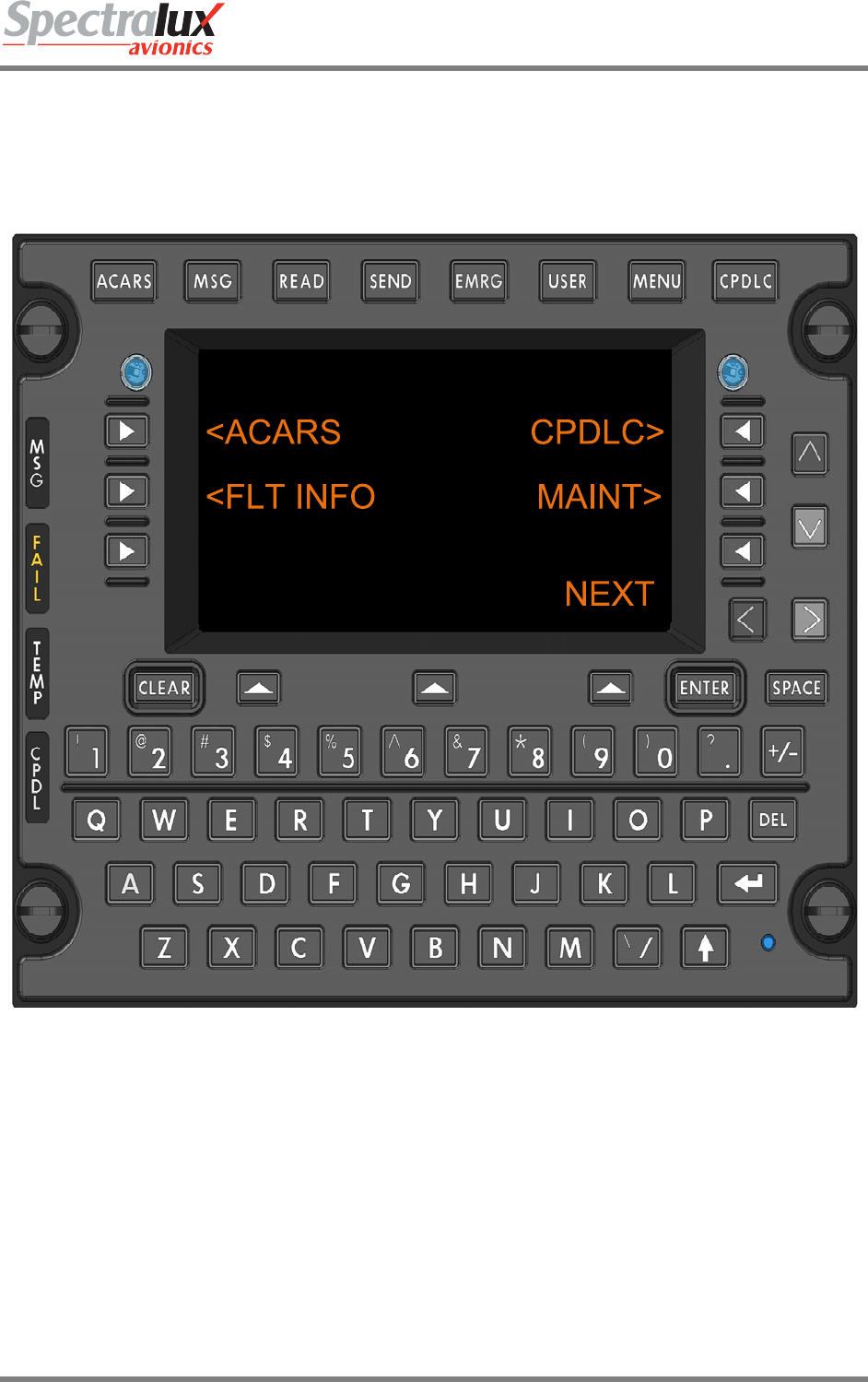
1.1 Using the Dlink+ w/CPDLC
The Dlink+ w/CPDLC emulates a 14-line ARINC 739 Multi-purpose Control and Display Unit (MCDU)
using a 9 line display to show the information in two parts called the A and B screens.
• The A screen puts the MCDU title line on line 1, MCDU lines 2 through 7 on display lines 2
through 7, and the MCDU scratch line (line 14) on line 8.
• The B screen puts the MCDU title line on line 1, MCDU lines 8 through 13 on display lines 2
through 7, and the MCDU scratch line (line 14) on line 8.
• When there is any text from MCDU line 8 through 13 on the B screen, the text above the lower
left Line Select Key (LSK) will read “A/B” and the rightmost character of display line 1 will show
the current screen (either A or B). Pressing the lower left LSK (“A/B”) will toggle between the two
screens.
T0 A
T1
T2
T3
T4
T5
T6
SCRATCH
A/B ADVISORY
T0 B
T7
T8
T9
T10
T11
T12
SCRATCH
A/B ADVISORY
Figure 1.1.1-1 Dlink+ w/CPDLC Text Line Identificaiton
Dlink+CPDLC Users Guide
Document Number: UG-14114 Rev. - Page 9 of 201
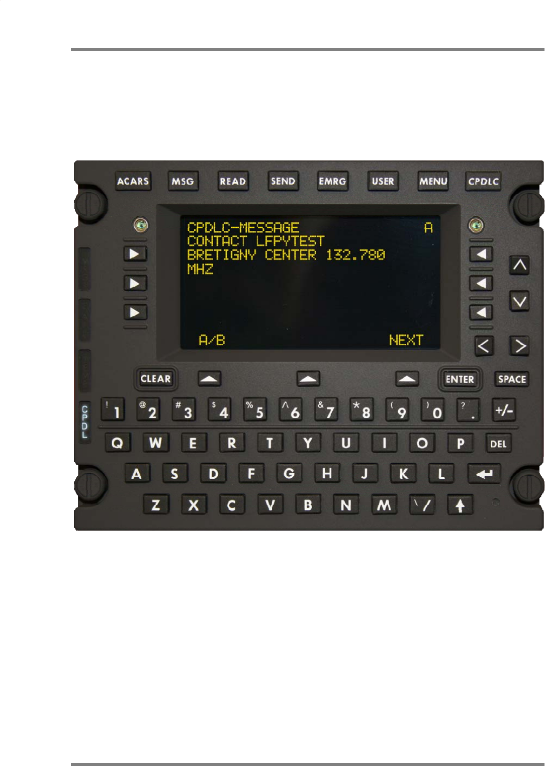
1.1.1 Basic User Interface
When first powered up or restarted, the Dlink+ w/CPDLC will appear as follows:
Note: The 1st line may have the airline name and unit version number.
1.1.2 Keyboard
Entering text from the keyboard will be shown on the “scratch pad” line located near the bottom of the
display. Entered text will start at column 1 and be added left to right. See Figure 1.1.1-1 Dlink+
w/CPDLC Text Line Identificaiton.
1.1.2.1 Alpha Numeric Keys
A standard QWERTY keyboard performs the expected functions. All alphabetic characters are always
upper case so they do not respond to the shift key.
1.1.2.2 Non Alpha Numeric Keys
1.1.2.2.1 User Function Keys
The user function keys are located at the top of the keyboard. Functionality is provided for each of
the keys. Function of each key is dependent on the state of the shift key.

Dlink+CPDLC Users Guide
Document Number: UG-14114 Rev. - Page 10 of 201
Functions associated with each non-shifted User Function Key:
• ACARS – Displays the ACARS Index Menu.
• MSG – Displays the ACARS messages log.
• READ – Displays the Monitor menu page.
• SEND – Displays the Aircrew Miscellaneous Message page.
• EMRG – Displays the E7500 Menu.
• USER – Displays the Main System User Menu.
• MENU – Displays the Subsystem Menu.
• CPDLC – Displays the CPDLC Index Menu.
The following functions associated with each shifted User Function Key:
• ACARS – Displays the ACARS Index Menu.
• MSG – Displays the ACARS messages log.
• READ – Displays the Station Table Menu.
• SEND – Displays the ATS Free Text Menu.
• EMRG – Displays the E7500 Menu
• USER – Print the current ACARS message if displayed else print current menu.
• MENU – Displays the Subsystem Menu.
• CPDLC – Displays the CPDLC Index Menu.
Pressing the MENU user key selects the MCDU MAIN MENU where any additional devices using
the Dlink+ w/CPDLC as an MCDU can be selected. Normally this only displays” <DLINK+” for the
Dlink+ w/CPDLC internal display functionality.
1.1.2.2.2 Line Select Keys
There are 9 Line Select Keys (LSKs): 3 on the left and right sides of the display and 3 below the
display.
The function of the 3 lower LSKs are:
1) LEFT is the A/B select. This LSK will toggle between A and B screens. If there is no text
on the B screen the LSK is ignored and the text above the key is blank. If this LSK is held
for 2 seconds a “lamp test” is performed. The annunciator lamps will illuminate briefly then
go out and all of the pixels on the display will turn on while the key is held.
2) CENTER is below the Advisory field. Its function changes depending of the content of the
advisory field.
3) RIGHT is the NEXT/PREV page key. When the shift light is off this is NEXT and when the
shift light is on this is the PREV key. When a menu contains multiple pages, the right end
of line 1 (next to the A/B character) displays “n/m” where “n” is the current page and “m” is
the total number of pages. Pressing NEXT increments the current page and pressing PREV
decrements it. If the menu contains only 1 page pressing this LSK will cause the data on
the display to be refreshed.
The three left and right LSKs map to the 6 MCDU left and right LSKs. When the A screen is
displayed they map to MCDU LSKs 1 through 3 and when the B screen is displayed they map to
MCDU LSKs 4 through 6. The character on the display closest to the LSK determines the
function the LSK will perform.
1) “<” or “>” indicates another menu will be displayed.
2) “*” indicates a function will be called or a message will be sent.
3) “[“ and “]” indicates a selection field and each press of the LSK will select the next item in
the selection list.

Dlink+CPDLC Users Guide
Document Number: UG-14114 Rev. - Page 11 of 201
4) Any other characters normally indicate a variable field for data entry. Pressing the LSK
while the scratch line is blank will cause the current contents of the LSK variable to be
copied to the scratch line for editing. Pressing the LSK when there is data on the scratch
line causes the contents of the scratch line to be copied to the LSK field. The data is
verified before it is inserted and an error message is display for any problems.
5) Text can also be displayed on a line next to an LSK and the LSK will have no defined
function. In this case, pressing the LSK will result in a warning on the scratch line.
1.1.2.2.3 Arrow Keys
The function of the up (^), down (v), left (<), and right (>) arrow keys changes depending on the
circumstances:
1) Normal operation: (Shift is off, no data on the scratch line)
• UP and DOWN move through multiple page menus ½ a screen at a time.
• LEFT is the equivalent of the Return key
• RIGHT is ignored.
2) Edit mode: (Shift is off, there is data on the scratch line)
• UP and DOWN have the same function as normal operation.
• LEFT and RIGHT move the cursor (an underscore) on the scratch line.
1.1.2.2.4 Clear Key
1) If a message is displayed on the scratch line it clears the message and restores the text
that was on the line.
2) If in edit mode it performs a backspace delete function.
3) If held for more than 1 second it clears the scratch line.
1.1.2.2.5 Enter Key
1) When data has been copied to the scratch line by pressing the associated LSK, pressing
ENTER stores the edited data to the original LSK field.
2) When entering a password the ENTER key enters and checks the password.
1.1.2.2.6 Del Key
The DEL key deletes the character under the cursor.
1.1.2.2.7 Return Key
The Return key returns to the previous menu if there is one. If there is no previous menu it is
ignored.
1.1.2.2.8 +/- Key
This key displays a minus in the scratch pad on the first press and will toggle to + with a second
press. It does not change based on the shift key.
1.1.2.2.9 Shift Key
The shift key operates as a shift lock key. Pressing it toggles the shifted/not shifted lamp (lamp is
on when shifted). Do not hold down the shift key to produce a symbol from the numeric keys.
Simply press shift once to turn on the lamp then press the numeric key to get the desired symbol.
Press shift again to turn it off.
1.1.3 Advisories
The Advisories alert the pilot to messages or problems.

Dlink+CPDLC Users Guide
Document Number: UG-14114 Rev. - Page 12 of 201
1.1.3.1 Lamps
1.1.3.1.1 MSG Lamp
The MSG lamp illuminates when there is at least one unread message in the ACARS receive
buffer. The user can press the MSG user function key to display the ACARS receive buffer. Once
all the message(s) has been viewed the light will be extinguished.
1.1.3.1.2 Fail Lamp
The FAIL lamp is illuminated when a failure is detected in the Dlink+ w/CPDLC. The Dlink+
w/CPDLC may perform an automatic reset to clear the problem. If the problem cannot be cleared
the FAIL lamp will stay on and the Dlink+ w/CPDLC is considered failed and should be serviced.
The particular failure status can be viewed from the Maintenance Menu.
1.1.3.1.3 Temp Lamp
The TEMP lamp will illuminate when the temperature inside the Dlink+ w/CPDLC is too cold (less
than -41C, -41F) or too hot (greater than 90C, 194F) to function.
The Dlink+ w/CPDLC will stay in reset until the temperature returns to normal operation range.
1.1.3.1.4 CPDL Lamp
The CPDL lamp illuminates when there is at least one unread message in the CPDLC receive
buffer. The user can press the CPDLC user function key to display the CPDLC receive buffer.
Once all the message(s) has been viewed the light will be extinguished.
1.1.3.2 Discrete Outputs
These outputs are available through the 61-pin connector on the back of the Dlink+ w/CPDLC.
1.1.3.2.1 ACARS Discrete Output
The ACARS Discrete output will follow the activity of the MSG Lamp, presenting an output ground
when the lamp is on and an open when the lamp is off on discrete output 3.
1.1.3.2.2 CPDLC Discrete Output
The CPDLC discrete output will follow the activity of the CPDL lamp, presenting an output ground
when the lamp is on and an output open when the lamp is off on discrete output 2.
1.1.3.2.3 CPDLC Chime Discrete Output
The CDPLC chime functionality is associated with the CPDL lamp and drives discrete output 1.
The output will present a ground when active and an open when not active. Characteristics of the
chime, pulse width and pulse spacing are part of the system configuration.
Dlink+CPDLC Users Guide
Document Number: UG-14114 Rev. - Page 13 of 201
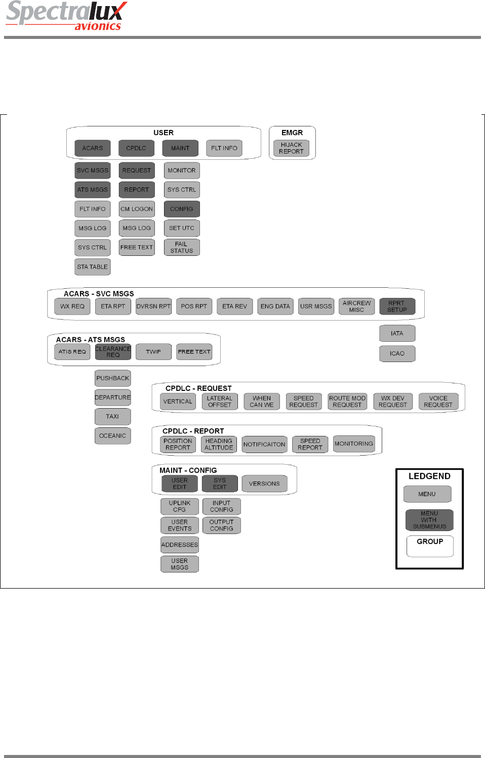
2 Menu Page Tree
Figure 1.1.3-1 Menu Tree

Dlink+CPDLC Users Guide
Document Number: UG-14114 Rev. - Page 14 of 201
2.1 Menu Parameter Description
Throughout this document the variable fields in menus will be described using notation listed in Table 1.
The fields in the menus are dynamic and will change as conditions or data changes.
Table 1 Variable Format Definition
Format
Identifier
Format Definition Example
A Alpha-numeric (AAAAA) – “DLINK”
N Numeric (N) – “1”
N.NN Numeric with decimal (N.NN) – “0.75”
SN Signed Numeric (SN) – “-9”
SN.N Signed Numeric with
decimal (SN.N) – “9.9”
B BCD (BBB) – “51E”
Z Numeric with leading zeros (ZZZ) – “042”
P Password (PPPPPP) – USER PASSWORD.
Will be displayed as “******”
Dlink+CPDLC Users Guide
Document Number: UG-14114 Rev. - Page 15 of 201
3 Common Menus
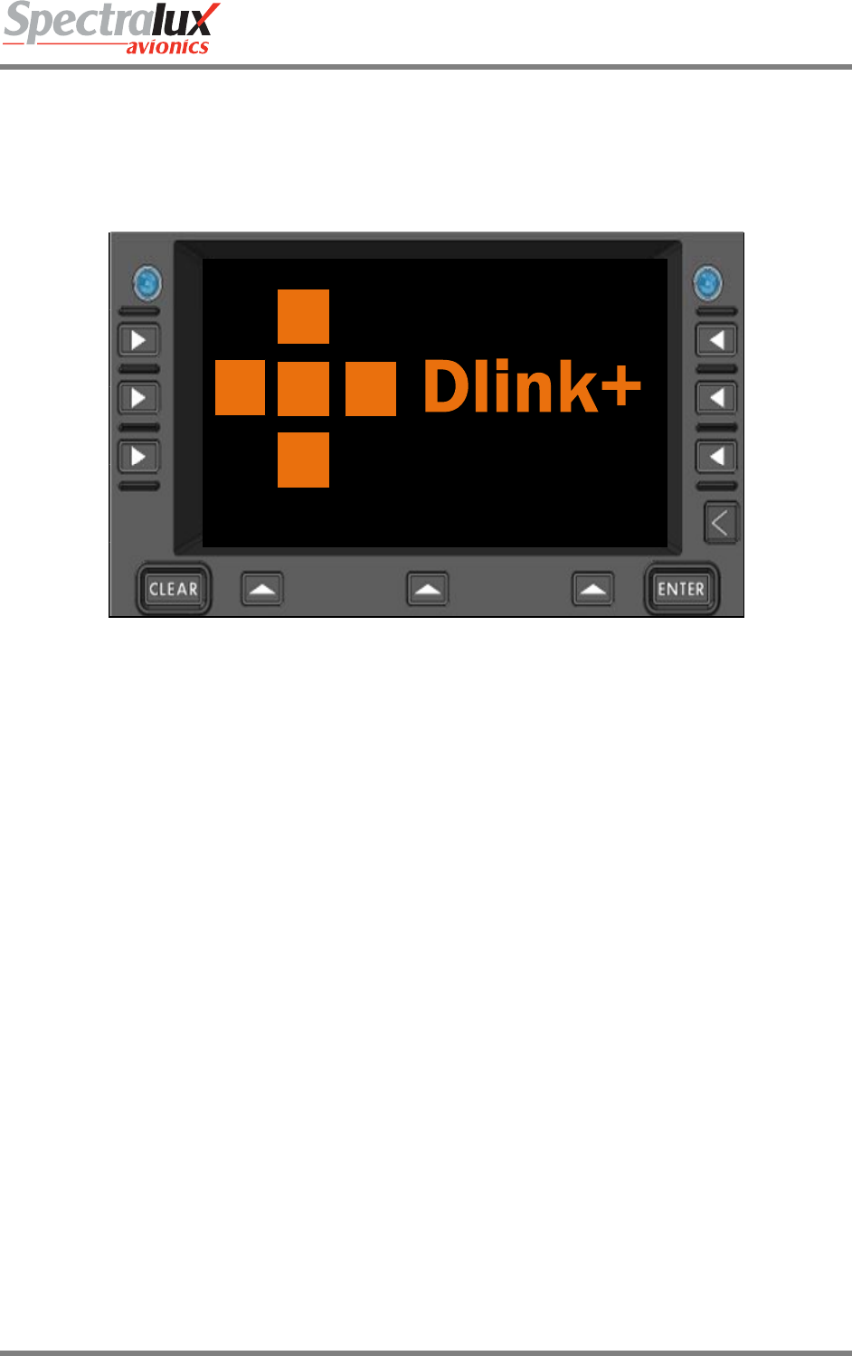
3.1 Splash Screen
The Splash screen is presented when the Dlink+ w/CPDLC is first powered on or after a restart. This
screen should stay present for approximately 5 seconds before transitioning to the main menu.
Figure 1.1.3-1 Splash Screen
Dlink+CPDLC Users Guide
Document Number: UG-14114 Rev. - Page 16 of 201
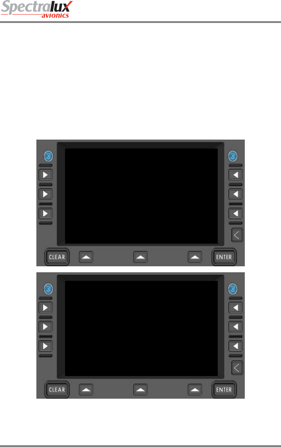
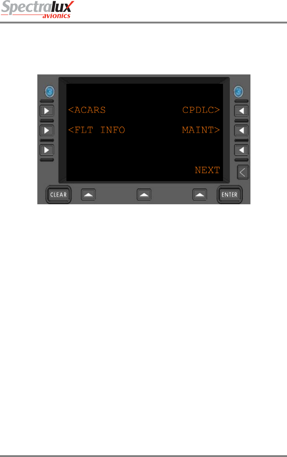
3.2 Main Menu
The Main menu is the starting or home menu, and can be accessed directly by pressing the USER key.
Note: The 1st line may have the airline name and unit version number.
Figure 1.1.3-1 Main Menu
<ACARS Navigate to the ACARS Menu
<FLT INFO Navigate to the Flight Information Menu
CPDLC> Navigate to the CPDLC Menu
MAINT> Navigate to the Maintenance Menu
RETURN Return to previous page
Dlink+CPDLC Users Guide
Document Number: UG-14114 Rev. - Page 17 of 201
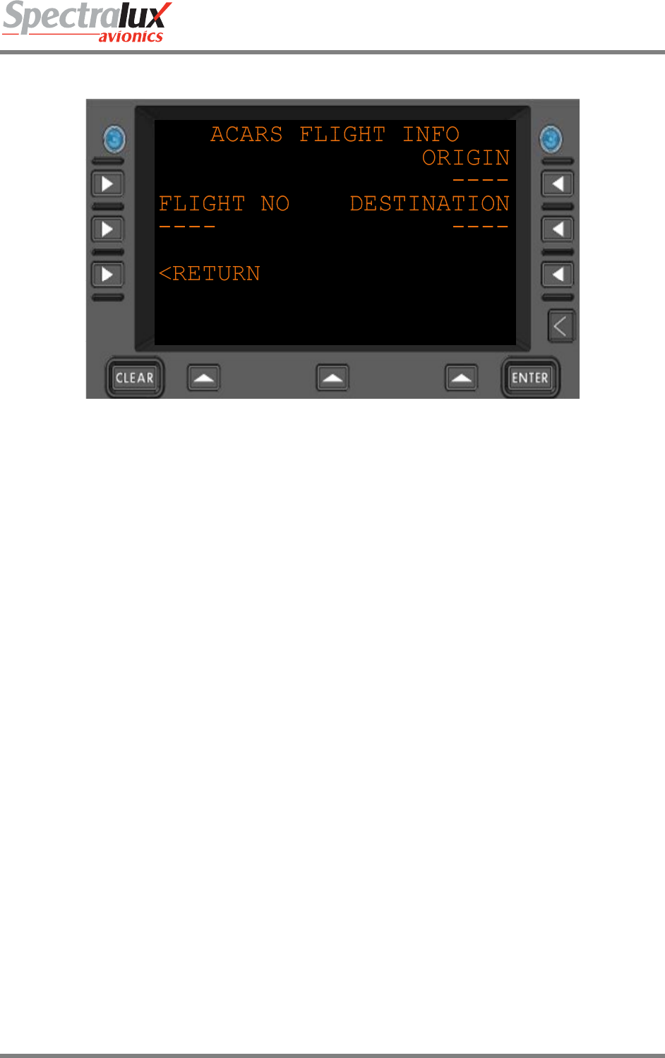
3.3 Main – Flight Information Menu
Figure 1.1.3-1 Flight Information Menu
FLIGHT NO Flight number.
Format: 1-4 alpha-numeric characters. (AAAA)
ORIGIN Flight departure (origin) station.
Format: 3-4 alpha characters (AAAA)
DESTINATION Flight destination station
Format: 3-4 alpha characters (AAAA)
RETURN Return to previous page
Dlink+CPDLC Users Guide
Document Number: UG-14114 Rev. - Page 18 of 201
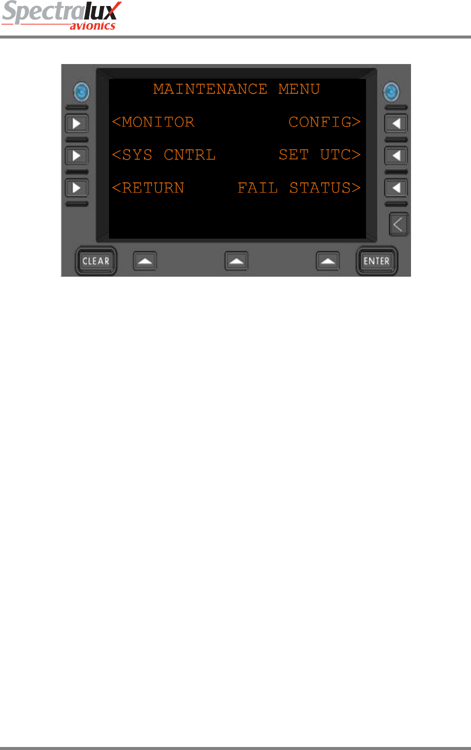
3.4 Main – Maintenance Menu
Figure 1.1.3-1 Maintenance Menu
<MONITOR Navigate to the MONITOR menu
<SYS CNTRL Navigate to the SYS CNTRL menu
CONFIG> Navigate to the CONFIG menu
SET UTC> Navigate to the SET UTC menu
FAIL STATUS> Navigate to the FAIL STATUS menu
<RETURN Return to previous page
Dlink+CPDLC Users Guide
Document Number: UG-14114 Rev. - Page 19 of 201
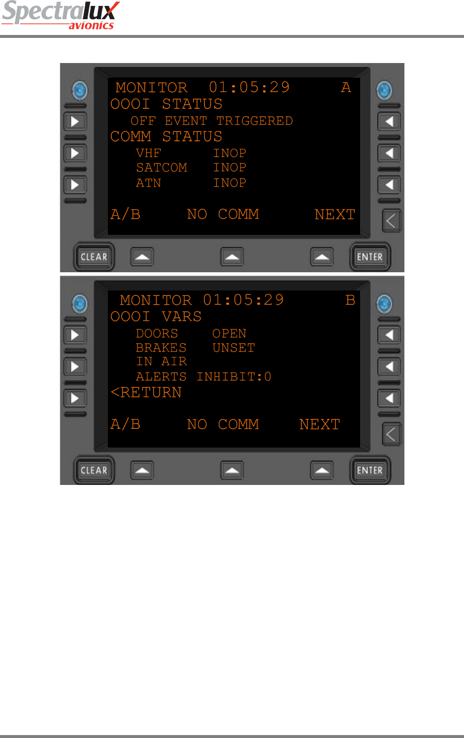
3.4.1 Maintenance – Monitor Menu Page 1
Figure 3.4.1-1 Monitor Menu 1
OOOI
Status
Reports the current state of the OOOIs
"INITIALIZING STATE...", "WAITING FOR OUT",
"OUT EVENT TRIGGERED", "RETURN EVENT TRIGGERED",
"OFF EVENT TRIGGERED", "ON EVENT TRIGGERED",
"IN EVENT TRIGGERED"
COMM
STATUS
Reports the current communication status
• VHF “INOP”,
“M2 AVAIL”,
“MA AVAIL”,
“NO COMM”
• SATCOM
“AVAILABLE”,
“NO COMM”,
“INOP”
• ATN “AVAILABLE”,

Dlink+CPDLC Users Guide
Document Number: UG-14114 Rev. - Page 20 of 201
“INOP”,
“UNAVAIL”
OOOI VARS Reports the current state of OOOI variables.
• DOORS
“DOORS CLOSED”,
“DOORS OPEN”
• BRAKES
“BRAKES UNSET”,
“BRAKES SET”
• AIR GROUND
“ON GROUND”,
“IN AIR”
• ALERTS INHIBIT
“0”,
“1”
<RETURN Return to previous page
Dlink+CPDLC Users Guide
Document Number: UG-14114 Rev. - Page 21 of 201
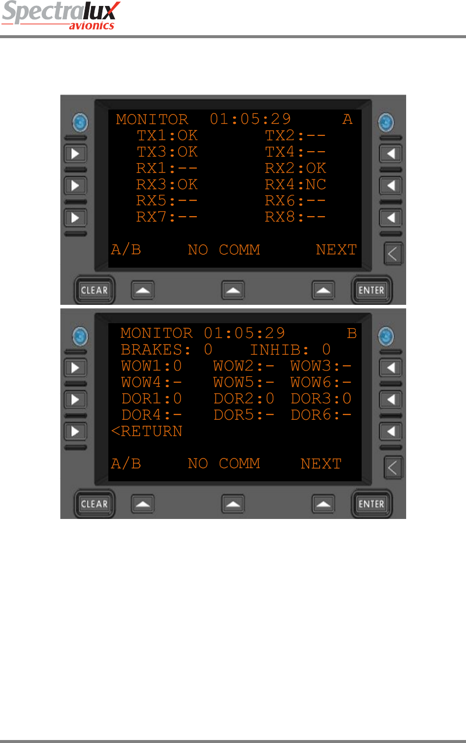
3.4.2 Maintenance – Monitor Menu Page 2
Figure 3.4.2-1 Monitor Menu 2
TX(1-4) or
RX(1-8)
The ARINC 429 channel being monitored.
Statuses:
“OK” – channel has valid activity
“NC” – channel has no valid activity
“- -“ – channel is not part of the system configuration.
Discrete
Inputs
WOW(1-6) – Weight On Wheels input used for Air / Ground logic.
DOR(1-6) – Doors used for all doors open / closed logic
BRAKES – input from the brakes used in brakes set logic.
INHIB – the “flaps up” signal used to inhibit annunciators.
<RETURN Return to previous page
Dlink+CPDLC Users Guide
Document Number: UG-14114 Rev. - Page 22 of 201
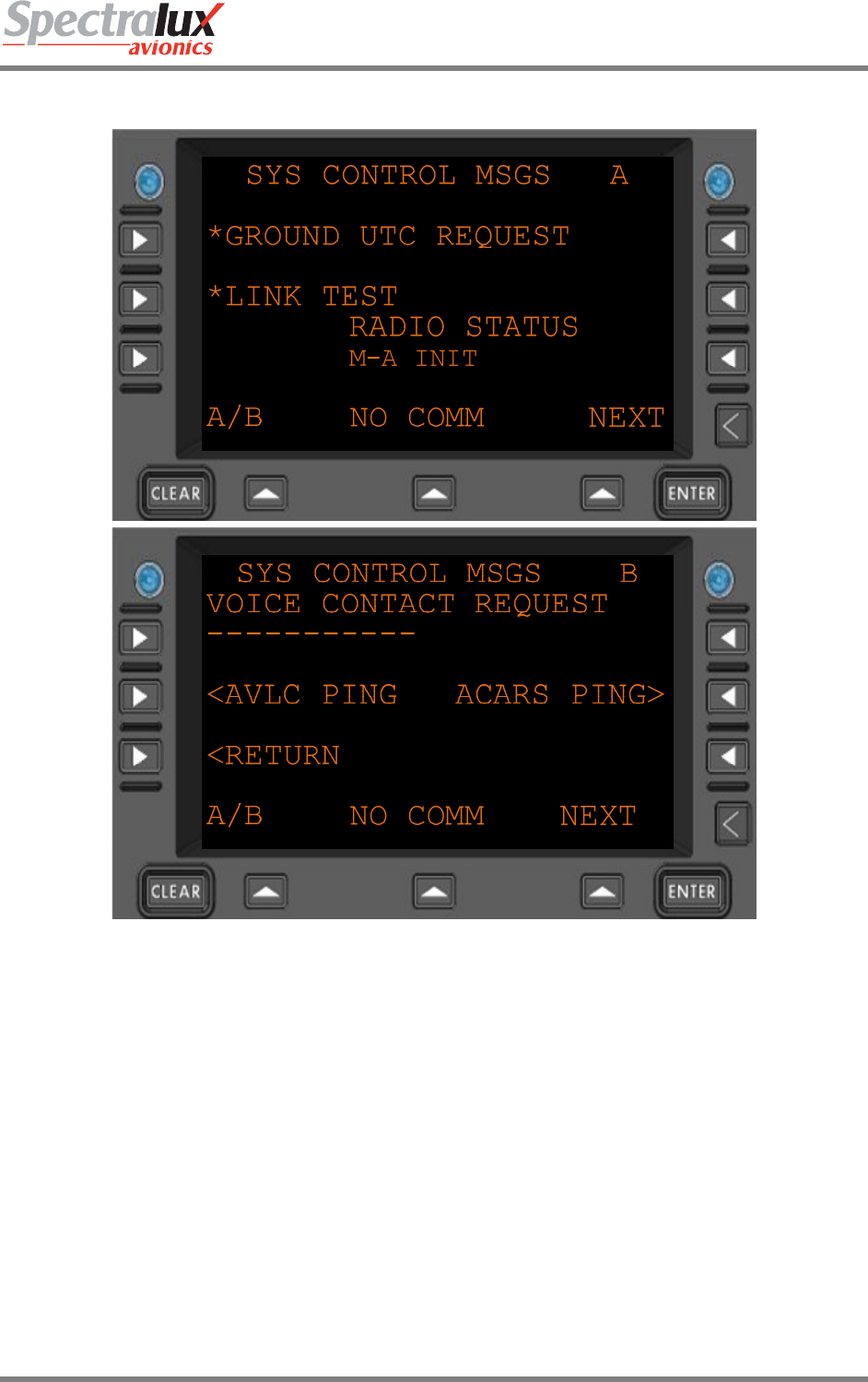
3.4.3 Maintenance – System Control Messages Menu
Figure 3.4.3-1 Sys Control Menu
*GROUND UTC
REQUEST
Send a Universal Coordinated Time request to the ground.
Flight number must be filled in prior to request being sent.
*LINK TEST Send a link test (Label Q0) to the ground.
Flight number must be filled in prior to request being sent.
RADIO STATUS The current radio operation. What is currently being sent or received
or follow-on operation due to previous uplink or downlink.
VOICE
CONTACT
REQUEST
Will send a Label 54 messages requesting voice contact at the entered
frequency.
Format: 10 digits (AAAAAAAAAA)
<AVLC PING Navigate to the AVLC PING menu
ACARS PING> Navigate to the ACARS PING menu
<RETURN Return to previous page
Dlink+CPDLC Users Guide
Document Number: UG-14114 Rev. - Page 23 of 201
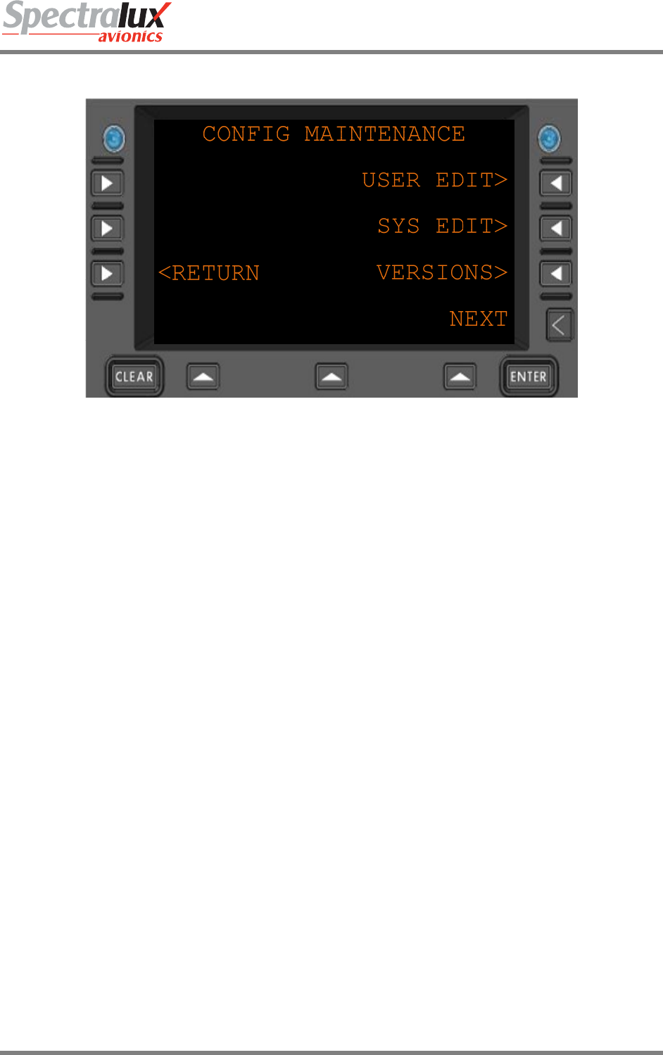
3.4.4 Maintenance – Configuration Maintenance Menu
Figure 3.4.4-1 Configuration Menu
USER EDIT> Navigate to the USER EDIT menu
SYS EDIT> Navigate to the SYS EDIT menu
VERSIONS> Navigate to the VERSIONS menu
<RETURN Return to previous page
Dlink+CPDLC Users Guide
Document Number: UG-14114 Rev. - Page 24 of 201
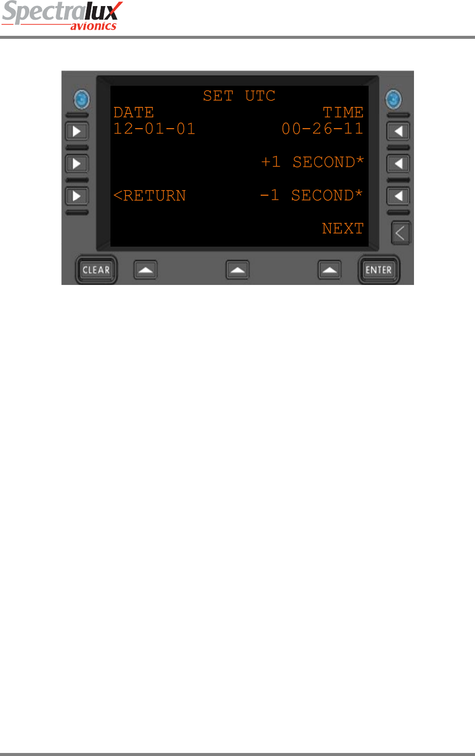
3.4.5 Maintenance - Set UTC Menu
Figure 3.4.5-1 Set UTC Menu
Date The current date
Format: MM-DD-YY
Time The current time
Format: HH-MM-SS
+1
SECOND*
Advance the current time by one second
-1
SECOND*
Retard the current time by one second.
<RETURN Return to previous page
Dlink+CPDLC Users Guide
Document Number: UG-14114 Rev. - Page 25 of 201
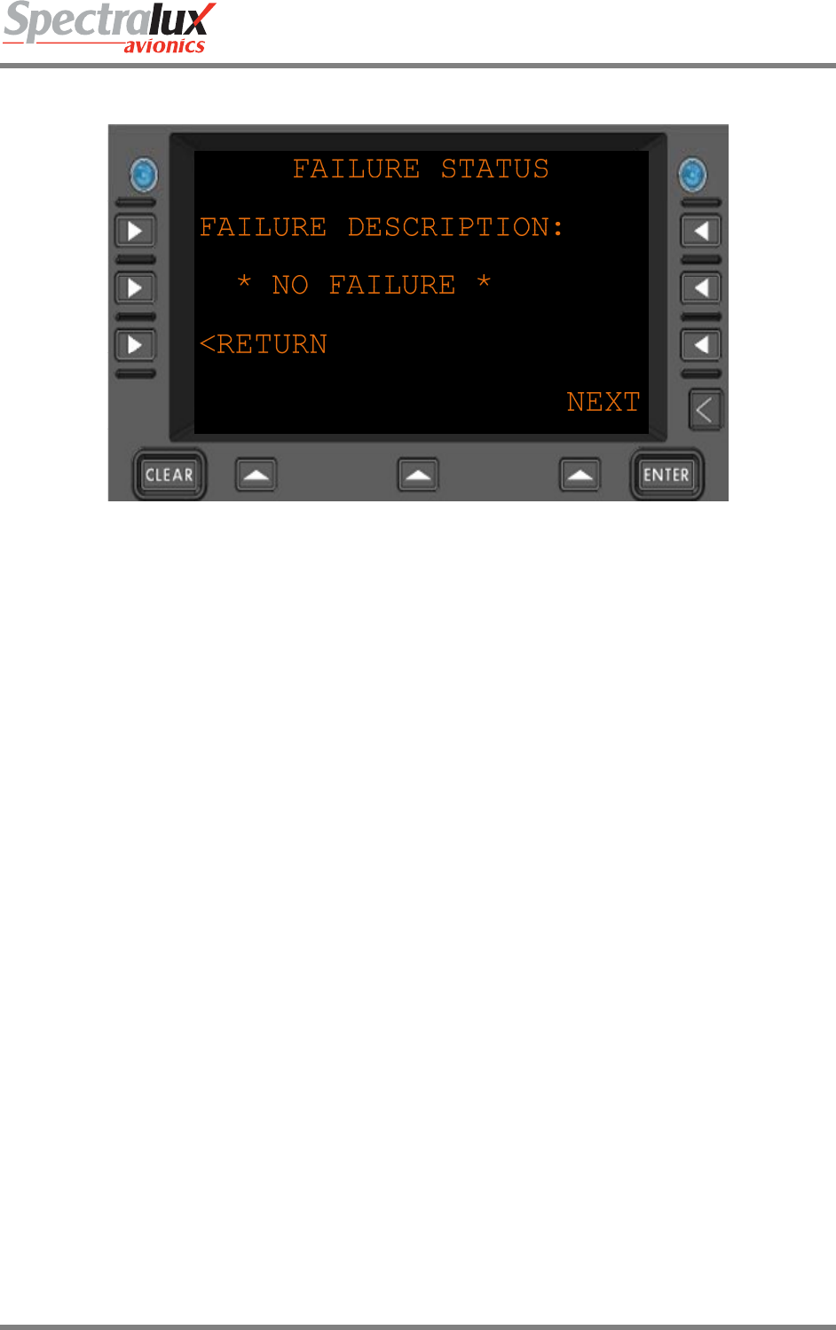
3.4.6 Maintenance – Fail Status Menu
Figure 3.4.6-1 Fail Status Menu
FAILURE
DESCRIPTION:
The Current failure, if present. The FAIL annunciator will also be lit if a
failure is present.
Format: 22 Characters
<RETURN Return to previous page
Dlink+CPDLC Users Guide
Document Number: UG-14114 Rev. - Page 26 of 201
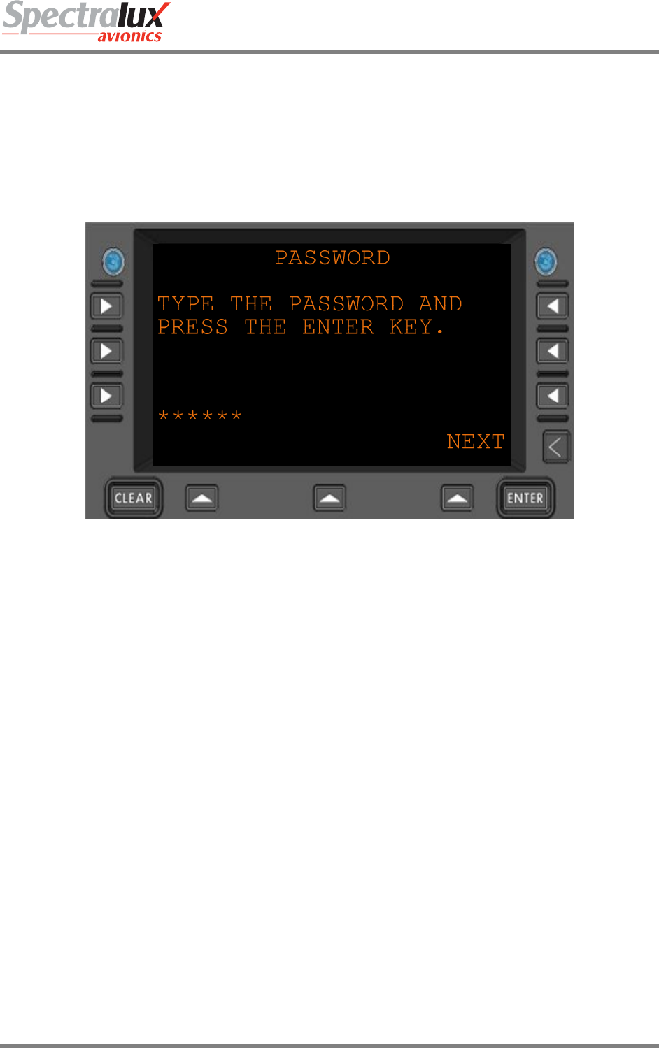
3.5 Configuration Maintenance Menu
The configuration information, accessed through the Configuration Maintenance Menu, is password
protected. There are two separate areas, User and System, each requiring a unique password. The
system password and access to its data area are only available to authorized Spectralux maintenance
personnel.
3.5.1 Configuration Maintenance – Password Menu
Figure 3.5.1-1 Password Menu
****** Password entered by the user
ENTER Pressing the ENTER key will accept the password

Dlink+CPDLC Users Guide
Document Number: UG-14114 Rev. - Page 27 of 201
3.5.2 Configuration Maintenance – User Edit Menu
See User Edit Menu
3.5.3 Configuration Maintenance – System Edit Menu
See System Edit Menu
3.5.4 Configuration Maintenance – Software Versions Menu
See User Edit Menu – Software Versions
Dlink+CPDLC Users Guide
Document Number: UG-14114 Rev. - Page 28 of 201
3.6 User Edit Menu
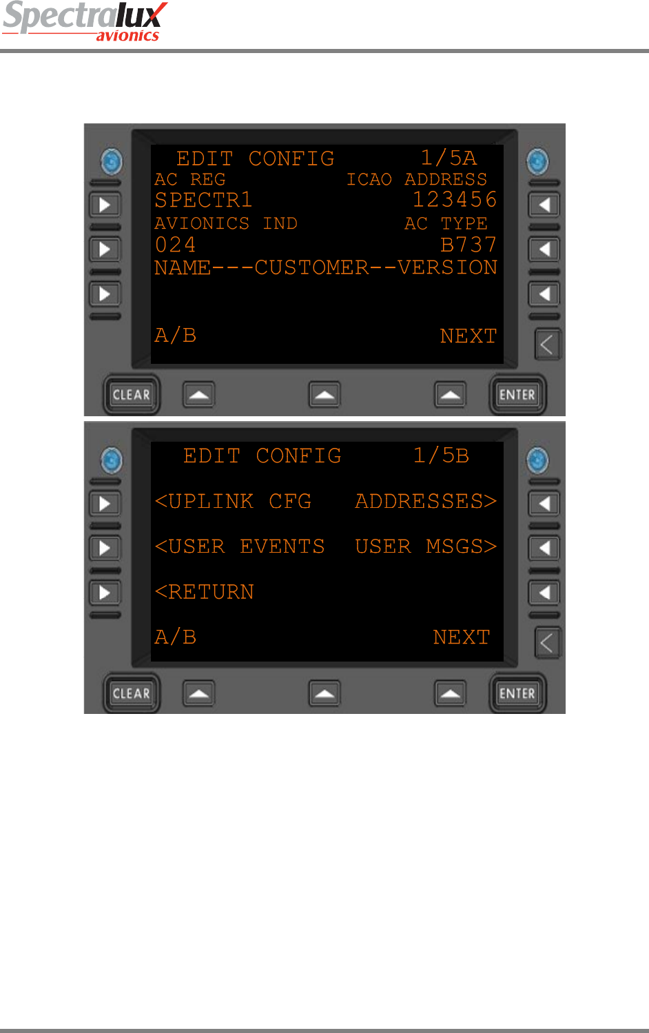
3.6.1 User Edit – Edit Configuration Menu Page 1
Figure 3.6.1-1 Edit Configuration Menu
AC REG Aircraft registration
Format: (AAAAAAA)
ICAO ADDRESS ICAO Address
Format: 6 hex-digits
AVIONICS IND Avionic indicator, the page width of printed messages.
Format: (ZZZ)
AC TYPE Aircraft type
Format: (AAAA)
CUSTOMER NAME Customer defined text
Format: 14 characters (AAAAAAAAAAAAAA)
CUSTOMER VERSION Customer defined text
Dlink+CPDLC Users Guide
Document Number: UG-14114 Rev. - Page 29 of 201
Format: (AAAAA)
<UPLINK CFG Navigate to the UPLINK CFG menu
<USER EVENTS Navigate to the USER EVENTS menu
ADDRESSES> Navigate to the ADDRESSES menu
USER MSGS> Navigate to the USER MSGS menu
<RETURN Return to previous page
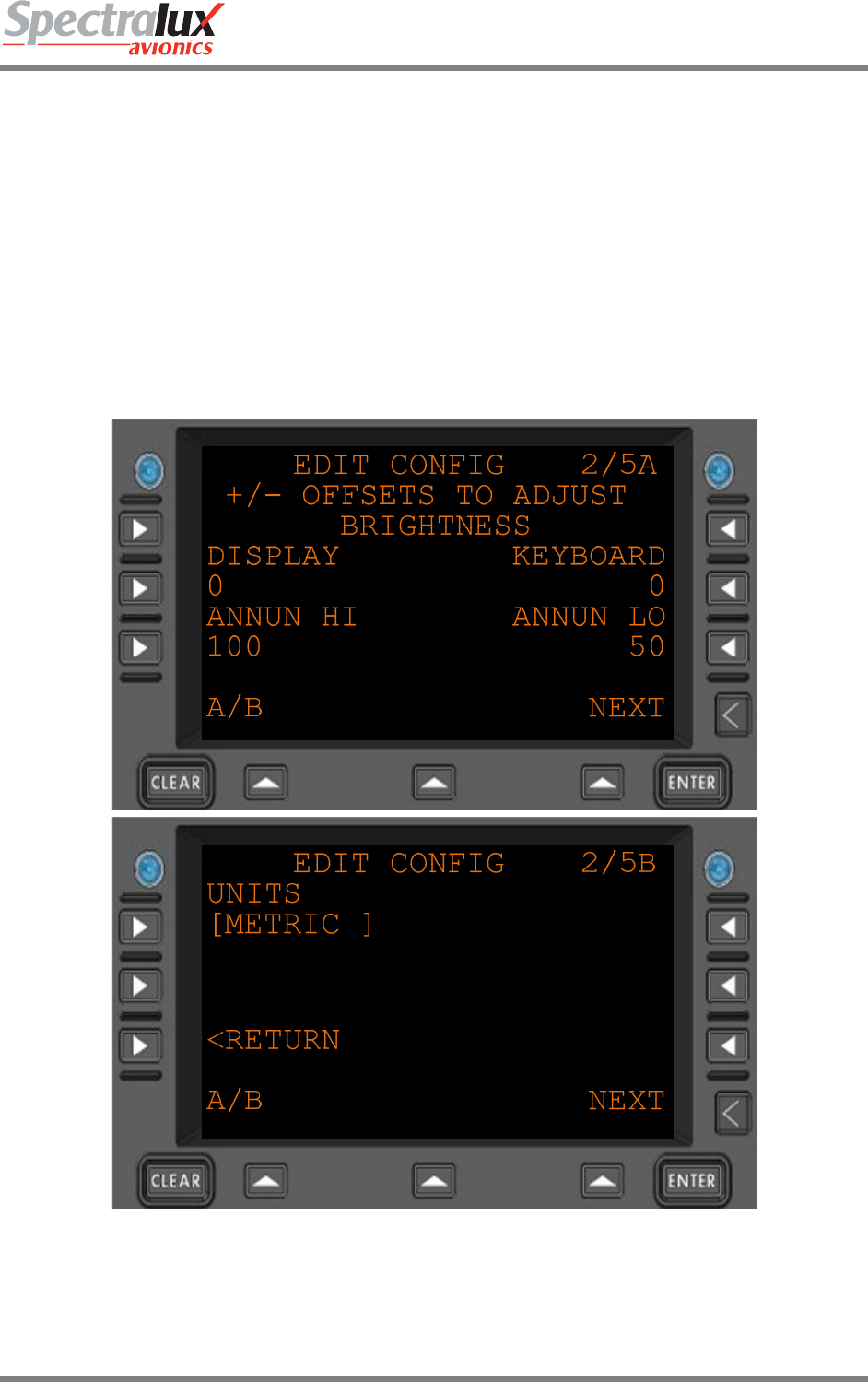
3.6.2 User Edit – Edit Configuration Menu Page 2
Figure 3.6.2-1 Edit Configuration Menu 2
DISPLAY Display brightness offset adjustment
Format: 4 digits, signed +/- 2000
Dlink+CPDLC Users Guide
Document Number: UG-14114 Rev. - Page 30 of 201
KEYBOARD Keyboard brightness offset adjustment
Format: 4 digits, signed +/- 2000
ANNUN HI Annunciator HI brightness offset adjustment
Format:3 digits. 0-100 percent
ANNUN LO Annunciator LO brightness offset adjustment
Format:3 digits 0-100 percent
UNITS Which format are units displayed in.
Format: “ENGLISH”, “METRIC”
<RETURN Return to the previous page.
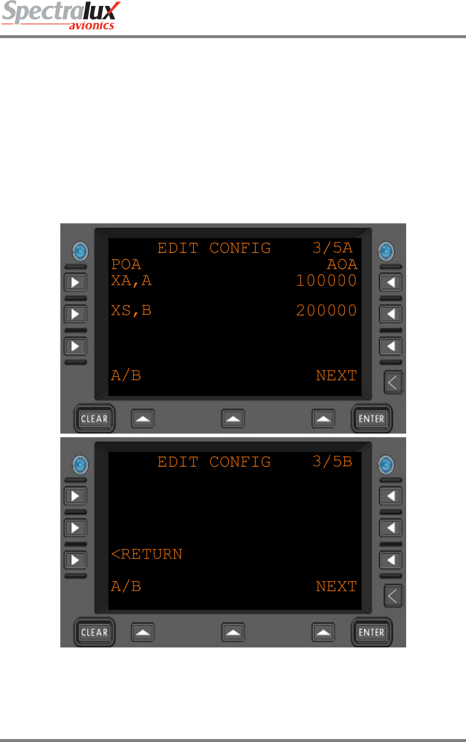
3.6.3 User Edit – Edit Configuration Menu Page 3
Figure 3.6.3-1 Edit Configuration Menu 3
POA A listing of the POA (Plain Old ACARS) service providers, in order of
preference.
Up to 3 can be listed.
Format: 4 characters (Service Provider [2 chars], “-“, Network type ( A or B )

Dlink+CPDLC Users Guide
Document Number: UG-14114 Rev. - Page 31 of 201
Typical: “XA,A” – ARINC or “XS,B” - SITA
AOA A listing of the AOA (ACARS over AVLC) service providers, in order of
preference.
Up to 3 can be listed.
Format: 6 hex-digits
Typical: “100000” – ARINC, “200000” - SITA
<RETURN Return to the previous page.
Dlink+CPDLC Users Guide
Document Number: UG-14114 Rev. - Page 32 of 201
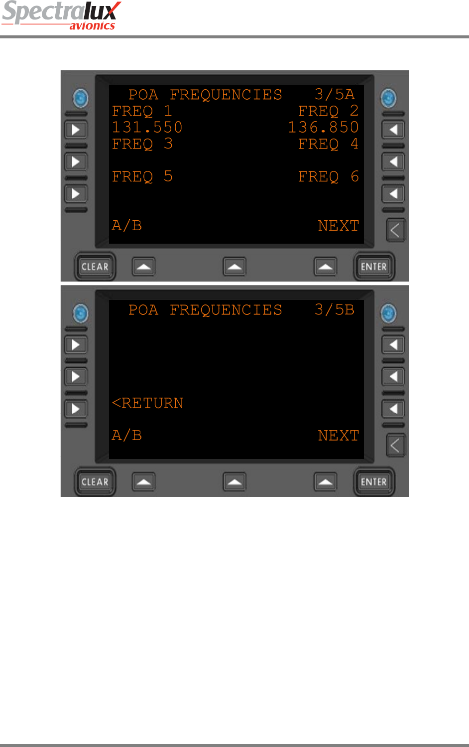
3.6.4 User Edit – Edit Configuration Menu Page 4
Figure 3.6.4-1 Edit Configuration POA Frequencies
FREQ 1 POA (Plain Old ACARS) base frequency
Format: NNN.NNN in 0.025 increments min = 118.000 max = 136.975
FREQ 2 POA (Plain Old ACARS) secondary frequency
Format: NNN.NNN in 0.025 increments min = 118.000 max = 136.975
FREQ 3 POA (Plain Old ACARS) secondary frequency
Format: NNN.NNN in 0.025 increments min = 118.000 max = 136.975
FREQ 4 POA (Plain Old ACARS) secondary frequency
Format: NNN.NNN in 0.025 increments min = 118.000 max = 136.975
FREQ 5 POA (Plain Old ACARS) secondary frequency
Format: NNN.NNN in 0.025 increments min = 118.000 max = 136.975
FREQ 6 POA (Plain Old ACARS) secondary frequency
Format: NNN.NNN in 0.025 increments min = 118.000 max = 136.975
<RETURN Return to the previous page.
Dlink+CPDLC Users Guide
Document Number: UG-14114 Rev. - Page 33 of 201
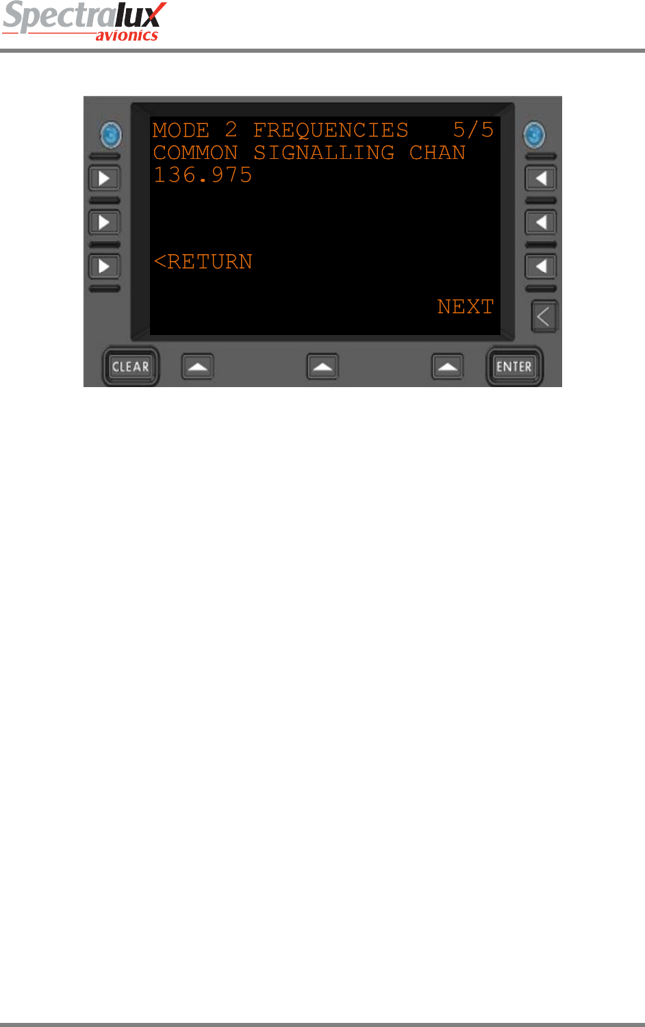
3.6.5 User Edit – Edit Configuration Menu Page 5
Figure 3.6.5-1 Edit Configuration Mode2 CSC
COMMON
SIGNALLING
CHAN
Base frequency for VDL Mode 2
<RETURN Return to the previous page.
Dlink+CPDLC Users Guide
Document Number: UG-14114 Rev. - Page 34 of 201
3.7 User Edit – Addresses Configuration Menu
ADDRESS CONFIG A
AC REG ICAO ADDRESS
------- 123456
NSAP 01-20
47002741534954001234
NSAP 21-40
56001000000000001011
A/B NEXT
ADDRESS CONFIG B
AGENCY CODE
--
<RETURN
A/B NEXT
Figure 3.6.5-1 Address Configuration Menu
AC REG The aircraft registration (AAAAAAA)
• The may contain a “-“ (dash) only if it is followed up by a number.
• The string may contain a “ “ (space) as long as the string stays within the 7
character limit. NOTE – Each space will count as 1 character
ICAO ADDRESS The ICAO address (6 hexadecimal digits)
NSAP 01-20 First 20 characters of the NSAP address. (20 hexadecimal digits)
NSAP 21-40 Second 20 characters of the NSAP address. (20 hexadecimal digits)
AGENCY CODE Airline agency code. (AA)
<RETURN Return to the previous page.
Dlink+CPDLC Users Guide
Document Number: UG-14114 Rev. - Page 35 of 201
3.8 User Edit – User Defined Uplinks Menu
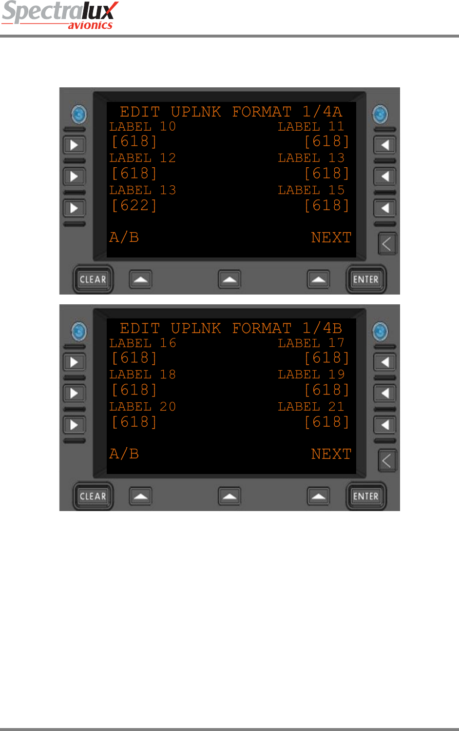
3.8.1 User Edit – Uplink Format Menu Page 1
Figure 3.8.1-1 Edit Uplink Format Menu 1
LABEL 10 Expected uplink format for messages with Label 10
Format: “618” , or “622”
LABEL 11 Expected uplink format for messages with Label 11
Format: “618” , or “622”
LABEL 12 Expected uplink format for messages with Label 12
Format: “618” , or “622”
LABEL 13 Expected uplink format for messages with Label 13
Format: “618” , or “622”
LABEL 14 Expected uplink format for messages with Label 14
Format: “618” , or “622”

Dlink+CPDLC Users Guide
Document Number: UG-14114 Rev. - Page 36 of 201
LABEL 15 Expected uplink format for messages with Label 15
Format: “618” , or “622”
LABEL 16 Expected uplink format for messages with Label 16
Format: “618” , or “622”
LABEL 17 Expected uplink format for messages with Label 17
Format: “618” , or “622”
LABEL 18 Expected uplink format for messages with Label 18
Format: “618” , or “622”
LABEL 19 Expected uplink format for messages with Label 19
Format: “618” , or “622”
LABEL 20 Expected uplink format for messages with Label 20
Format: “618” , or “622”
LABEL 21 Expected uplink format for messages with Label 21
Format: “618” , or “622”
Dlink+CPDLC Users Guide
Document Number: UG-14114 Rev. - Page 37 of 201
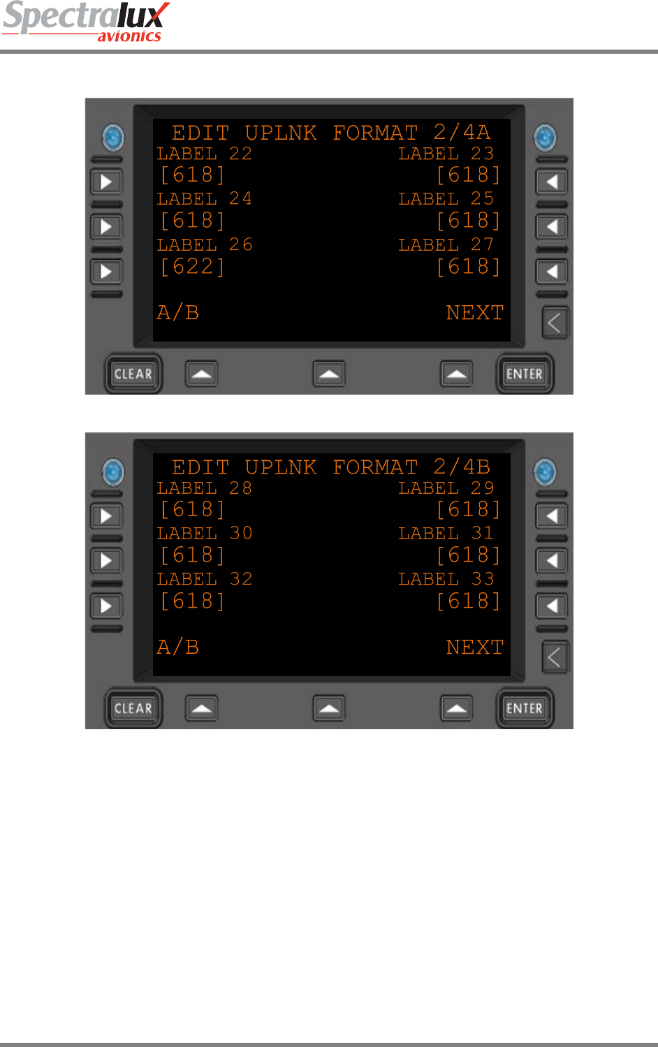
3.8.2 User Edit – Uplink Format Menu Page 2
Figure 3.8.2-1 Edit Uplink Formant Menu 2
LABEL 22 Expected uplink format for messages with Label 22
Format: “618” , or “622”
LABEL 23 Expected uplink format for messages with Label 23
Format: “618” , or “622”
LABEL 24 Expected uplink format for messages with Label 24
Format: “618” , or “622”
LABEL 25 Expected uplink format for messages with Label 25
Format: “618” , or “622”
LABEL 26 Expected uplink format for messages with Label 26
Format: “618” , or “622”

Dlink+CPDLC Users Guide
Document Number: UG-14114 Rev. - Page 38 of 201
LABEL 27 Expected uplink format for messages with Label 27
Format: “618” , or “622”
LABEL 28 Expected uplink format for messages with Label 28
Format: “618” , or “622”
LABEL 29 Expected uplink format for messages with Label 29
Format: “618” , or “622”
LABEL 30 Expected uplink format for messages with Label 30
Format: “618” , or “622”
LABEL 31 Expected uplink format for messages with Label 31
Format: “618” , or “622”
LABEL 32 Expected uplink format for messages with Label 32
Format: “618” , or “622”
LABEL 33 Expected uplink format for messages with Label 33
Format: “618” , or “622”
Dlink+CPDLC Users Guide
Document Number: UG-14114 Rev. - Page 39 of 201
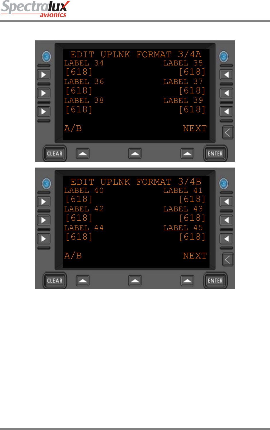
3.8.3 User Edit – Uplink Format Menu Page 3
Figure 3.8.3-1 Edit Uplink Format Menu 3
LABEL 34 Expected uplink format for messages with Label 22
Format: “618” , or “622”
LABEL 35 Expected uplink format for messages with Label 23
Format: “618” , or “622”
LABEL 36 Expected uplink format for messages with Label 24
Format: “618” , or “622”
LABEL 37 Expected uplink format for messages with Label 25
Format: “618” , or “622”
LABEL 38 Expected uplink format for messages with Label 26
Format: “618” , or “622”
LABEL 39 Expected uplink format for messages with Label 27

Dlink+CPDLC Users Guide
Document Number: UG-14114 Rev. - Page 40 of 201
Format: “618” , or “622”
LABEL 40 Expected uplink format for messages with Label 28
Format: “618” , or “622”
LABEL 41 Expected uplink format for messages with Label 29
Format: “618” , or “622”
LABEL 42 Expected uplink format for messages with Label 30
Format: “618” , or “622”
LABEL 43 Expected uplink format for messages with Label 31
Format: “618” , or “622”
LABEL 44 Expected uplink format for messages with Label 32
Format: “618” , or “622”
LABEL 45 Expected uplink format for messages with Label 33
Format: “618” , or “622”
Dlink+CPDLC Users Guide
Document Number: UG-14114 Rev. - Page 41 of 201
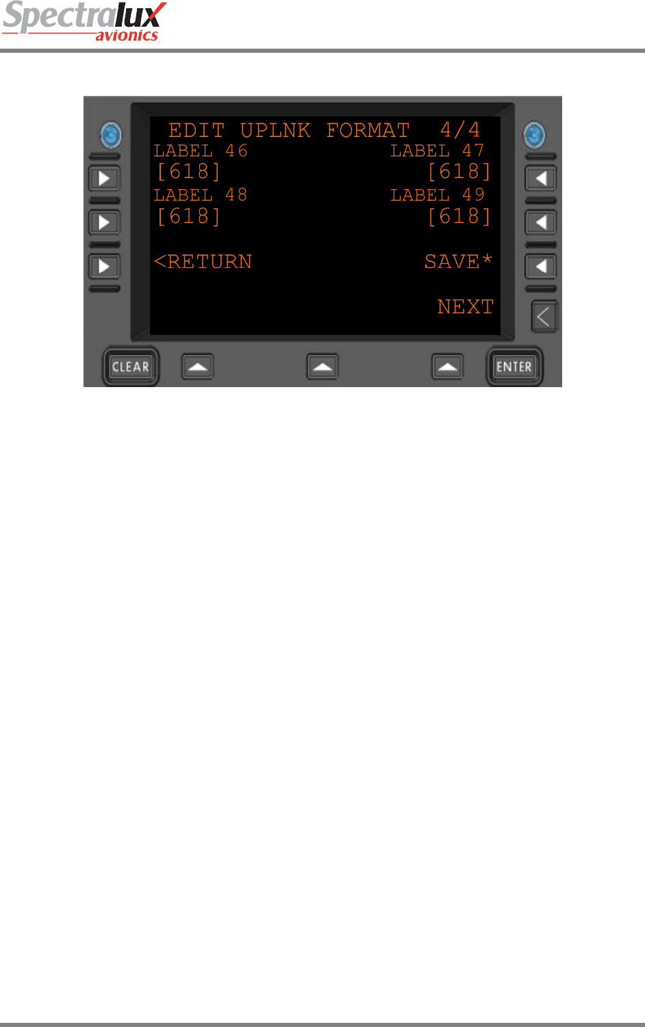
3.8.4 User Edit – Uplink Format Menu Page 4
Figure 3.8.4-1 Edit Uplink Format Menu 4
LABEL 46 Expected uplink format for messages with Label 46
Format: “618” , or “622”
LABEL 47 Expected uplink format for messages with Label 47
Format: “618” , or “622”
LABEL 48 Expected uplink format for messages with Label 48
Format: “618” , or “622”
LABEL 49 Expected uplink format for messages with Label 49
Format: “618” , or “622”
SAVE* Save the modified expected uplink formats
<RETURN Return to previous page
Dlink+CPDLC Users Guide
Document Number: UG-14114 Rev. - Page 42 of 201
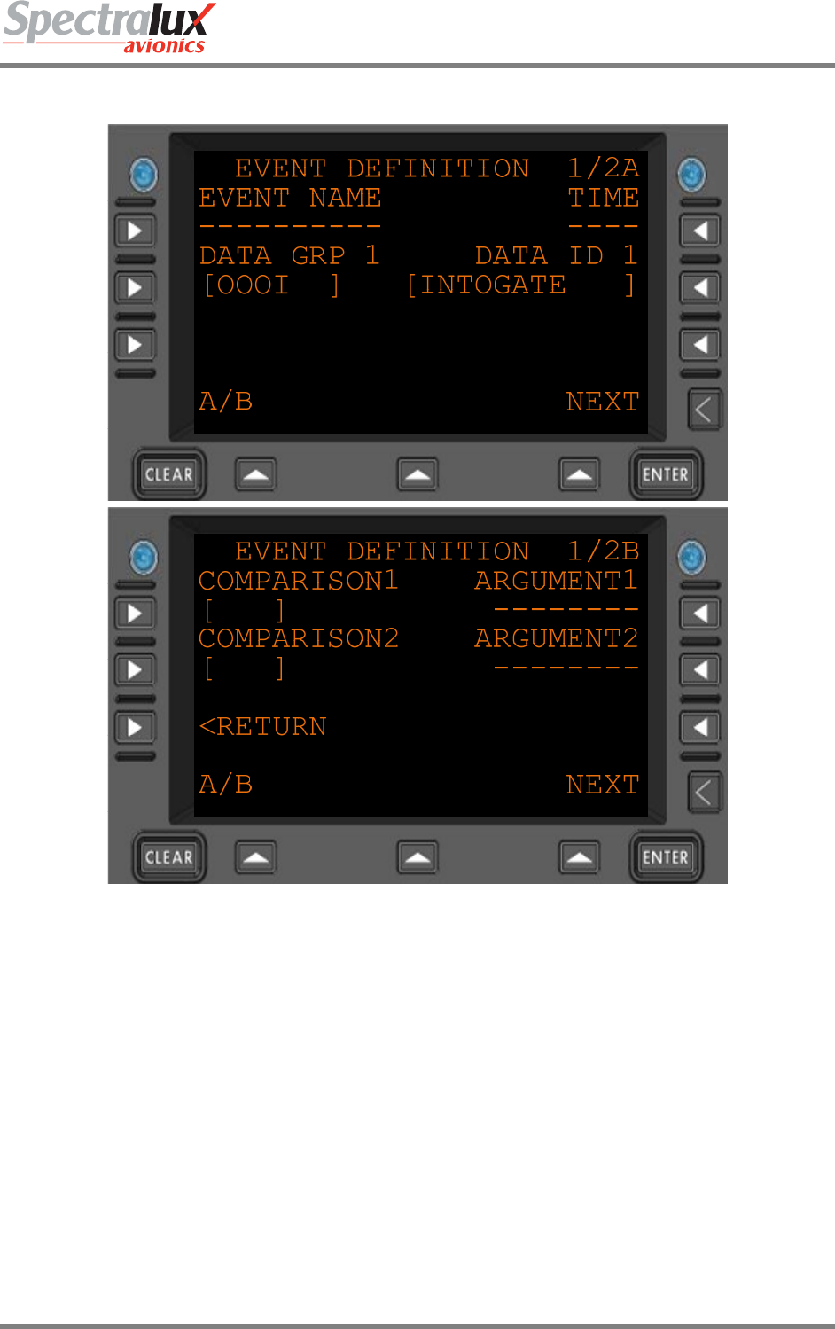
3.9 User Event – User Defined Events Menu
Figure 3.8.4-1 User Defined Event Edit Menu Page 1
EVENT NAME The name of the event. This is used to uniquely identify and describe the event.
Additionally it is used to link a user defined message to the event. Maximum 10
characters in length.
TIME Interval – (0–9999) Number of seconds to require the event to be TRUE for before the
event is actually considered triggered. If no criteria are specified in this interval then it
is interpreted to be 0 seconds. If no conditions are elsewhere specified in the event,
then the event is simply triggered once every this number of seconds.
DATA GRP 1 Which grouping is the data ID to be collected from. The groups are:
OOOI, AIR DATA, NAV DATA, ENG DATA 1, ENG DATA 2, ENG DATA 3, ENG
DATA 4, ENGDATAAVG, FLT CNTRL
DATA ID 1 Which data item from Data Group 1 will be used for the event.
Dlink+CPDLC Users Guide
Document Number: UG-14114 Rev. - Page 43 of 201
COMPARISON 1 Which comparison should take place between Argument 1 and Data ID 1.
The possible comparisons will be one of the following :
• “ “ :No Comparator (default)
• “= “: Equals
• “>=”: Greater Than or Equal
• “> “: Greater Than
• “< “: Lesser Than
• “<=”: Lesser Than or Equal
COMPARISON 2 Comparator with format identical to Comparator 1 with the distinction that it represents
the comparison between Data ID 1 and Argument 2.
ARGUMENT 1 Argument to be compared with Data ID 1 using Comparator 1. It is a maximum of 8
characters in length and can be any real number that can be contained in those 8
characters, including decimal points and negative signs as characters.
ARGUMENT 2 Argument with format identical to Argument 1 with the distinction that it represents the
data to be compared with Data ID 1 using Comparator 2.
<RETURN Return to previous page
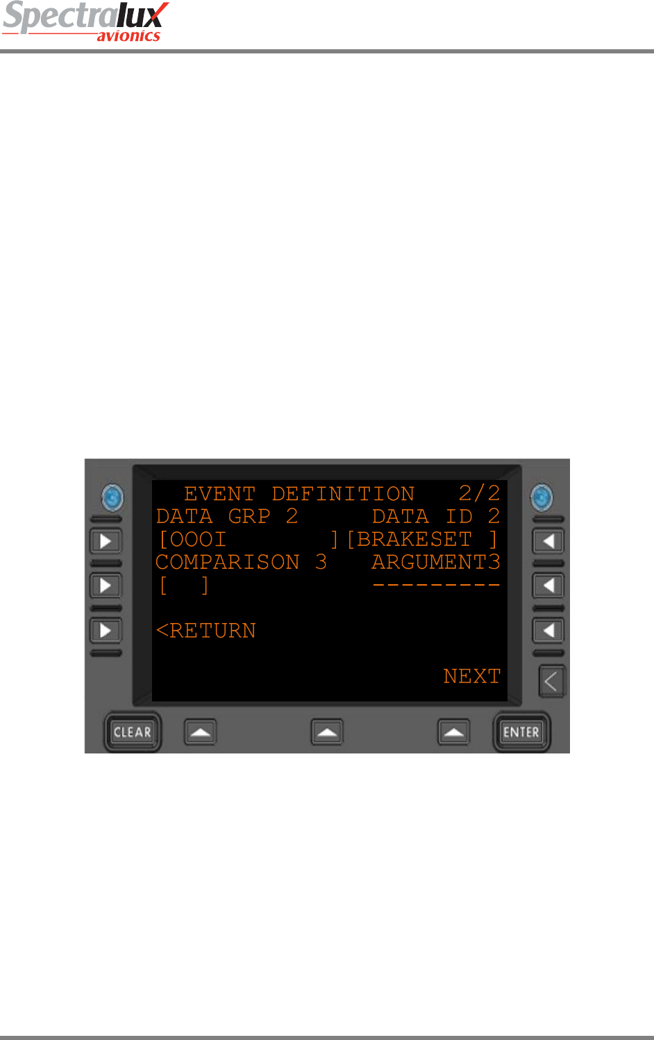
Figure 3.8.4-2 User Defined Event Edit Menu Page 2
DATA GRP 2 The data group from which DATA ID 2 will be collected.
DATA ID 2 Indicating the second data ID in use by the event. Its format is identical to the
format of Data ID 1
COMPARISON 3 Comparator with format identical to Comparator 1 with the distinction that it
represents the comparison between Data ID 2 and Argument 3
ARGUMENT 3 Argument with format identical to Argument 1 with the distinction that it
represents the data to be compared with Data ID 2 using Comparator 3.
<RETURN Return to previous page
Dlink+CPDLC Users Guide
Document Number: UG-14114 Rev. - Page 44 of 201
3.10 User Edit – User Defined Messages Menu
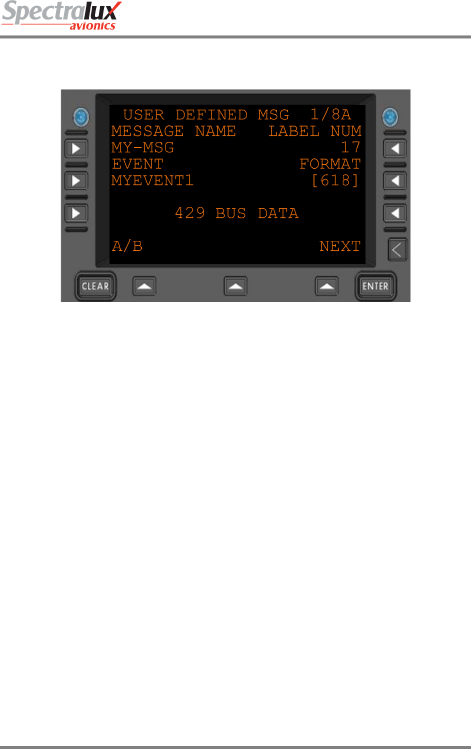
3.10.1 User Edit – User Defined Message Edit Menu Page 1
Figure 3.10.1-1 User Defined Message Edit Menu 1
MESSAGE NAME The name of the message represented to the user when they are selecting a user
defined message to Send/Edit/Delete. Maximum 14 characters in length.
EVENT The name of the event that triggers the transmission of this user defined message.
Maximum 10 characters in length can be empty to indicate that the message may
only be transmitted upon pilot input.
LABEL NUM The ACARS label attached to the message.
FORMAT Indicates if the message is an ARINC 618 or ARINC 622 message.
429 BUS DATA The following menus provide a checkbox to select which data will be included in the
message.
Dlink+CPDLC Users Guide
Document Number: UG-14114 Rev. - Page 45 of 201
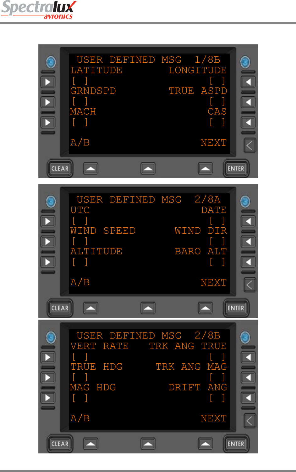
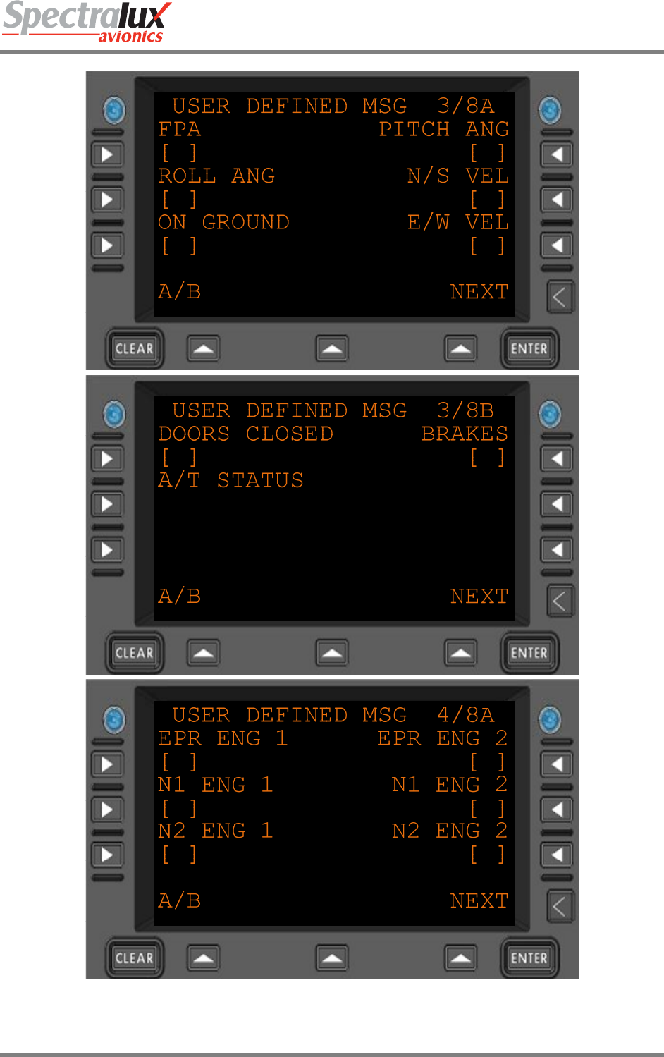
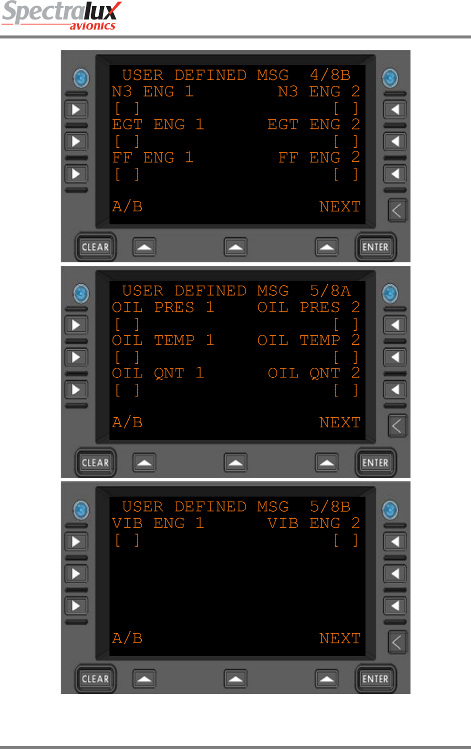
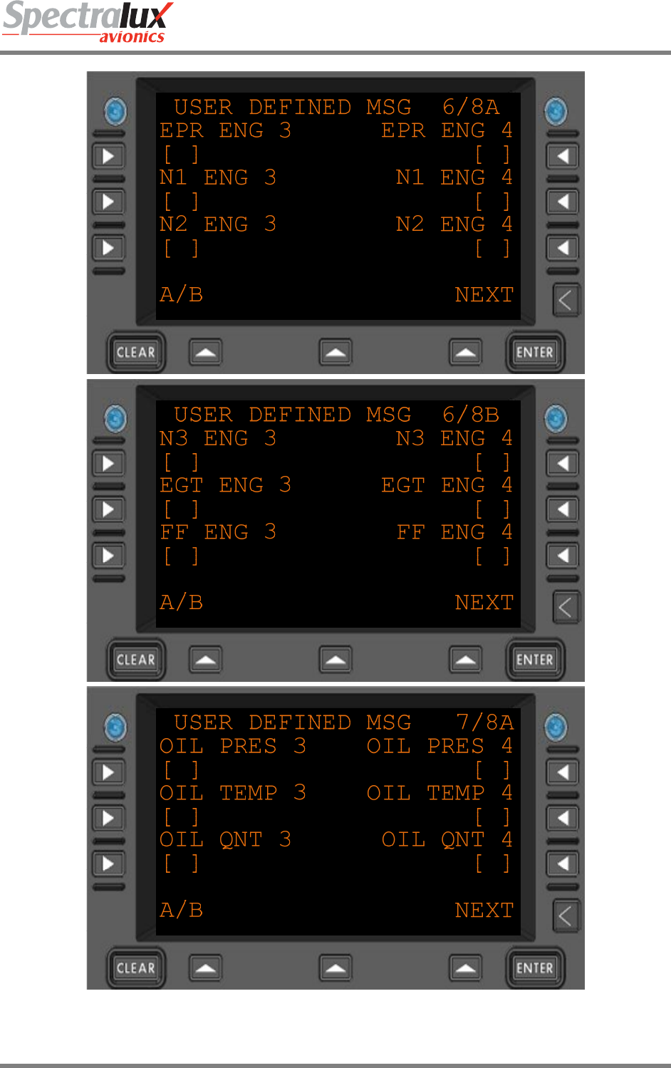
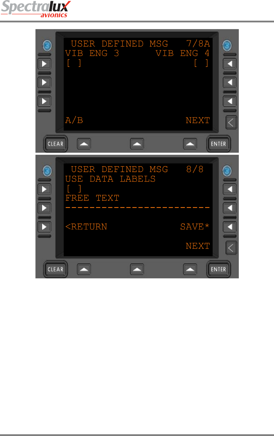
3.10.2 User Edit – User Defined Message Edit Menu Page 2
Dlink+CPDLC Users Guide
Document Number: UG-14114 Rev. - Page 46 of 201
Dlink+CPDLC Users Guide
Document Number: UG-14114 Rev. - Page 47 of 201
Dlink+CPDLC Users Guide
Document Number: UG-14114 Rev. - Page 48 of 201
Dlink+CPDLC Users Guide
Document Number: UG-14114 Rev. - Page 49 of 201
Figure 3.10.2-1 User Defined Message Edit Data Menus
USE DATA
LABELS
Will the data labels be included in the message.
FREE TEXT Every user defined downlink can have up to 24 characters of free text
appended to it prior to transmission.
SAVE Commit this user defined message to the configuration module. Will cause
the Dlink+ w/CPDLC to reboot after saving.
<RETURN Return to previous page
Dlink+CPDLC Users Guide
Document Number: UG-14114 Rev. - Page 50 of 201
3.10.3 Definition of Optional Data in User Defined Messages
Data
Format and Space Requirements Example w/ Total Character Space Req'd
Label Format/Separator w/ Label w/o Label
Latitude LAT: 5 NDDMM.MM 8 , 2 LAT: NDDMM.MM, 15 NDDMM.MM, 10
Longitude LON: 5 NDDDMM.MM 9 , 2 LON: NDDDMM.MM, 16 NDDDMM.MM, 11
Date DATE: 6 DDMMYY 6 , 2 DATE: DDMMYY, 14 DDMMYY, 8
UTC UTC: 5 HHMM.M 6 , 2 UTC: HHMM.M, 13 HHMM.M, 8
Altitude ALT: 5 NNNNN 5 , 2 ALT: NNNNN, 12 NNNNN, 7
Baro Altitude BAROALT: 9 NNNNN 5 , 2 BAROALT: NNNNN, 16 NNNNN, 7
Magnetic Heading MAGHDG: 8 NNN.N 5 , 2 MAGHDG: NNN.N, 15 NNN.N, 7
True Heading TRUHDG: 8 NNN.N 5 , 2 TRUHDG: NNN.N, 15 NNN.N, 7
Track Angle True TRKANGTRU: 11 NNN.N 5 , 2 TRKANGTRU:
NNN.N, 18 NNN.N, 7
Track Angle Mag TRKANGMAG: 11 NNN 3 , 2 TRKANGMAG: NNN, 16 NNN, 5
Drift Angle DRIFTANG: 10 NNN 3 , 2 DRIFTANG: NNN, 15 NNN, 5
Flight Path Angle FPA: 5 NNN 3 , 2 FPA: NNN, 10 NNN, 5
Ground Speed GRNDSPD: 9 NNNN 4 , 2 GRNDSPD: NNNN, 15 NNNN, 6
True Airspeed TAS: 5 NNN 3 , 2 TAS: NNN, 10 NNN, 5
Mach MACH: 6 N.NNN 5 , 2 MACH: N.NNN, 13 N.NNN, 7
CAS CAS: 5 NNN 3 , 2 CAS: NNN, 10 NNN, 5
Vertical Rate VRATE: 7 SNNNNN 6 , 2 VRATE: SNNNNN, 15 SNNNNN, 8
N/S VelocityInertial
Vertical Speed NSVEL:
INERTVSPD: 711 NNNNSNNNNN 46 ,
, 22
NSVEL: NNNN,
INERTVSPD:
SNNNNN, 13
19 NNNN,
SNNNNN, 68
E/W VelocityN/S
Velocity EWVEL: NSVEL: 77 NNNNNNNN 44 ,
, 22 EWVEL: NNNN,
NSVEL: NNNN, 13
13 NNNN,
NNNN, 66
Pitch AngleE/W
Velocity PITCH: EWVEL: 77 SNNNNNN 34 ,
, 22 PITCH: SNN,
EWVEL: NNNN, 12
13 SNN, NNNN, 56
Roll AnglePitch
Angle ROLL: PITCH: 67 SNNSNN 33 ,
, 22 ROLL: SNN,
PITCH: SNN, 11
12 SNN, SNN, 55
Wind SpeedRoll
Angle WINDSPD: ROLL: 96 NNNSNN 33 ,
, 22 WINDSPD: NNN,
ROLL: SNN, 14
11 NNN, SNN, 55
Wind DirectionWind
Speed WINDDIR:
WINDSPD: 99 SNNNNNN 43 ,
, 22 WINDDIR: SNNN,
WINDSPD: NNN, 15
14 SNNN, NNN, 65
Total Air
TemperatureWind
Direction TAT: WINDDIR: 59 SNNSNNN 34 ,
, 22 TAT: SNN,
WINDDIR: SNNN, 10
15 SNN, SNNN, 56
Outside Air
TemperatureTotal
Air Temperature OAT: TAT: 55 SNNSNN 33 ,
, 22 OAT: SNN, TAT:
SNN, 10
10 SNN, SNN, 55
On GroundOutside
Air Temperature ONGROUND: OAT: 105 NSNN 13 ,
, 22 ONGROUND: N,
OAT: SNN, 13
10 N, SNN, 35
Doors ClosedOn
Ground DOORSCLSD:
ONGROUND: 1110 NN 11 ,
, 22 DOORSCLSD: N,
ONGROUND: N, 14
13 N, N, 33
Brakes SetDoors
Closed BRAKESSET:
DOORSCLSD: 1111 NN 11 ,
, 22 BRAKESSET: N,
DOORSCLSD: N, 14
14 N, N, 33
AT SDI Brakes Set ATSDI:
BRAKESSET: 711 N 01 ,
, 22 ATSDI: ,
BRAKESSET: N, 91
4 , N, 23
AT Status AT SDI ATSTAT: ATSDI: 87 00 , 22 ATSTAT: , ATSDI: 10 , , 22
Dlink+CPDLC Users Guide
Document Number: UG-14114 Rev. - Page 51 of 201
, , 9
EPR Engine 1AT
Status EPRENG1: ATSTAT: 98 N 10 ,
, 22 EPRENG1: N,
ATSTAT: , 12
10 N, , 32
EPR Engine 2EPR
Engine 1 EPRENG2:
EPRENG1: 99 NN 11 ,
, 22 EPRENG2: N,
EPRENG1: N, 12
12 N, N, 33
EPR Engine 3EPR
Engine 2 EPRENG3:
EPRENG2: 99 NN 11 ,
, 22 EPRENG3: N,
EPRENG2: N, 12
12 N, N, 33
EPR Engine 4EPR
Engine 3 EPRENG4:
EPRENG3: 99 NN 11 ,
, 22 EPRENG4: N,
EPRENG3: N, 12
12 N, N, 33
N1 Engine 1EPR
Engine 4 N1ENG1: EPRENG4: 89 N 01 ,
, 22 N1ENG1: ,
EPRENG4: N, 10
12 , N, 23
N1 Engine 2N1
Engine 1 N1ENG2: N1ENG1: 88 00 ,
, 22 N1ENG2: ,
N1ENG1: , 10
10 , , 22
N1 Engine 3N1
Engine 2 N1ENG3: N1ENG2: 88 00 ,
, 22 N1ENG3: ,
N1ENG2: , 10
10 , , 22
N1 Engine 4N1
Engine 3 N1ENG4: N1ENG3: 88 00 ,
, 22 N1ENG4: ,
N1ENG3: , 10
10 , , 22
N2 Engine 1N1
Engine 4 N2ENG1: N1ENG4: 88 00 ,
, 22 N2ENG1: ,
N1ENG4: , 10
10 , , 22
N2 Engine 2N2
Engine 1 N2ENG2: N2ENG1: 88 00 ,
, 22 N2ENG2: ,
N2ENG1: , 10
10 , , 22
N2 Engine 3N2
Engine 2 N2ENG3: N2ENG2: 88 00 ,
, 22 N2ENG3: ,
N2ENG2: , 10
10 , , 22
N2 Engine 4N2
Engine 3 N2ENG4: N2ENG3: 88 00 ,
, 22 N2ENG4: ,
N2ENG3: , 10
10 , , 22
N3 Engine 1N2
Engine 4 N3ENG1: N2ENG4: 88 00 ,
, 22 N3ENG1: ,
N2ENG4: , 10
10 , , 22
N3 Engine 2N3
Engine 1 N3ENG2: N3ENG1: 88 00 ,
, 22 N3ENG2: ,
N3ENG1: , 10
10 , , 22
N3 Engine 3N3
Engine 2 N3ENG3: N3ENG2: 88 00 ,
, 22 N3ENG3: ,
N3ENG2: , 10
10 , , 22
N3 Engine 4N3
Engine 3 N3ENG4: N3ENG3: 88 00 ,
, 22 N3ENG4: ,
N3ENG3: , 10
10 , , 22
EGT Engine 1N3
Engine 4 EGTENG1: N3ENG4: 98 00 ,
, 22 EGTENG1: ,
N3ENG4: , 11
10 , , 22
EGT Engine 2EGT
Engine 1 EGTENG2:
EGTENG1: 99 00 ,
, 22 EGTENG2: ,
EGTENG1: , 11
11 , , 22
EGT Engine 3EGT
Engine 2 EGTENG3:
EGTENG2: 99 00 ,
, 22 EGTENG3: ,
EGTENG2: , 11
11 , , 22
EGT Engine 4EGT
Engine 3 EGTENG4:
EGTENG3: 99 00 ,
, 22 EGTENG4: ,
EGTENG3: , 11
11 , , 22
FF Engine 1EGT
Engine 4 FFENG1: EGTENG4: 89 00 ,
, 22 FFENG1: ,
EGTENG4: , 10
11 , , 22
FF Engine 2FF
Engine 1 FFENG2: FFENG1: 88 00 ,
, 22 FFENG2: ,
FFENG1: , 10
10 , , 22
FF Engine 3FF
Engine 2 FFENG3: FFENG2: 88 00 ,
, 22 FFENG3: ,
FFENG2: , 10
10 , , 22
FF Engine 4FF
Engine 3 FFENG4: FFENG3: 88 00 ,
, 22 FFENG4: ,
FFENG3: , 10
10 , , 22
BB Engine 1FF
Engine 4 BBENG1: FFENG4: 88 00 ,
, 22 BBENG1: ,
FFENG4: , 10
10 , , 22
BB Engine 2BB
Engine 1 BBENG2: BBENG1: 88 00 ,
, 22 BBENG2: ,
BBENG1: , 10
10 , , 22
BB Engine 3BB
Engine 2 BBENG3: BBENG2: 88 00 ,
, 22 BBENG3: ,
BBENG2: , 10
10 , , 22

Dlink+CPDLC Users Guide
Document Number: UG-14114 Rev. - Page 52 of 201
BB Engine 4BB
Engine 3 BBENG4: BBENG3: 88 00 ,
, 22 BBENG4: ,
BBENG3: , 10
10 , , 22
Oil Pressure
Engine 1
BB Engine 4 OILPRESENG1:
BBENG4: 138 00 ,
, 22 OILPRESENG1: ,
BBENG4: , 15
10 , , 22
Oil Pressure
Engine 2
Oil Pressure
Engine 1 OILPRESENG2:
OILPRESENG1: 1313 00 ,
, 22 OILPRESENG2: ,
OILPRESENG1: , 15
15 , , 22
Oil Pressure
Engine 3
Oil Pressure
Engine 2 OILPRESENG3:
OILPRESENG2: 1313 00 ,
, 22 OILPRESENG3: ,
OILPRESENG2: , 15
15 , , 22
Oil Pressure Engine
4Oil Pressure
Engine 3 OILPRESENG4:
OILPRESENG3: 1313 00 ,
, 22 OILPRESENG4: ,
OILPRESENG3: , 15
15 , , 22
Oil Temperature
Engine 1
Oil Pressure
Engine 4 OILTEMPENG1:
OILPRESENG4: 1313 SNNN 40 ,
, 22
OILTEMPENG1:
SNNN,
OILPRESENG4: , 19
15 SNNN, , 62
Oil Temperature
Engine 2
Oil Temperature
Engine 1 OILTEMPENG2:
OILTEMPENG1: 1313 SNNNSNNN 44 ,
, 22
OILTEMPENG2:
SNNN,
OILTEMPENG1:
SNNN, 19
19 SNNN,
SNNN, 66
Oil Temperature
Engine 3
Oil Temperature
Engine 2 OILTEMPENG3:
OILTEMPENG2: 1313 SNNNSNNN 44 ,
, 22
OILTEMPENG3:
SNNN,
OILTEMPENG2:
SNNN, 19
19 SNNN,
SNNN, 66
Oil Temperature
Engine 4
Oil Temperature
Engine 3 OILTEMPENG4:
OILTEMPENG3: 1313 SNNNSNNN 44 ,
, 22
OILTEMPENG4:
SNNN,
OILTEMPENG3:
SNNN, 19
19 SNNN,
SNNN, 66
Vibration Engine 1
Oil Temperature
Engine 4 VIBENG1:
OILTEMPENG4: 913 NSNNN 14 ,
, 22
VIBENG1: N,
OILTEMPENG4:
SNNN, 12
19 N, SNNN, 36
Vibration Engine 2
Vibration Engine 1 VIBENG2:
VIBENG1: 99 NN 11 ,
, 22 VIBENG2: N,
VIBENG1: N, 12
12 N, N, 33
Vibration Engine 3
Vibration Engine 2 VIBENG3:
VIBENG2: 99 NN 11 ,
, 22 VIBENG3: N,
VIBENG2: N, 12
12 N, N, 33
Vibration Engine
4Vibration Engine 3 VIBENG4:
VIBENG3: 99 NN 11 ,
, 22 VIBENG4: N,
VIBENG3: N, 12
12 N, N, 33
Duct Pressure
Engine 1
Vibration Engine 4 DUCTPRESENG1:
VIBENG4: 149 N 01 ,
, 22 DUCTPRESENG1: ,
VIBENG4: N, 16
12 , N, 23
Duct Pressure
Engine 2
Duct Pressure
Engine 1 DUCTPRESENG2:
DUCTPRESENG1: 1414 00 ,
, 22 DUCTPRESENG2: ,
DUCTPRESENG1: , 16
16 , , 22
Duct Pressure
Engine 3
Duct Pressure
Engine 2 DUCTPRESENG3:
DUCTPRESENG2: 1414 00 ,
, 22 DUCTPRESENG3: ,
DUCTPRESENG2: , 16
16 , , 22
Dlink+CPDLC Users Guide
Document Number: UG-14114 Rev. - Page 53 of 201
Duct Pressure
Engine 4
Duct Pressure
Engine 3 DUCTPRESENG4:
DUCTPRESENG3: 1414 00 ,
, 22 DUCTPRESENG4: ,
DUCTPRESENG3: , 16
16 , , 22
AC Pack Engine 1
Duct Pressure
Engine 4 ACPACKENG1:
DUCTPRESENG4: 1214 00 ,
, 22 ACPACKENG1: ,
DUCTPRESENG4: , 14
16 , , 22
AC Pack Engine 2
AC Pack Engine 1 ACPACKENG2:
ACPACKENG1: 1212 00 ,
, 22 ACPACKENG2: ,
ACPACKENG1: , 14
14 , , 22
AC Pack Engine 3
AC Pack Engine 2 ACPACKENG3:
ACPACKENG2: 1212 00 ,
, 22 ACPACKENG3: ,
ACPACKENG2: , 14
14 , , 22
AC Pack Engine 4
AC Pack Engine 3 ACPACKENG4:
ACPACKENG3: 1212 00 ,
, 22 ACPACKENG4: ,
ACPACKENG3: , 14
14 , , 22
AC Pack Engine 4 VERTG1:
ACPACKENG4: 812 00 ,
, 22 VERTG1: ,
ACPACKENG4: , 10
14 , , 22
Free Text RMK: VERTG4:
VERTG3: 588 FREE TEXT 2400 ,
, 022
RMK: FREE
TEXTVERTG4: ,
VERTG3: ,
29
10
10 FREE TEXT,
, 2422
Free Text RMK: VERTG4: 58 FREE TEXT 240 , 02 RMK: FREE
TEXTVERTG4: , 29
10 FREE TEXT, 242
Free Text RMK: 5 FREE TEXT 24 0 RMK: FREE TEXT 29 FREE TEXT 24
Table 2 Required Character Space for Optional Data in User Defined Messages
Dlink+CPDLC Users Guide
Document Number: UG-14114 Rev. - Page 54 of 201
3.11 User Edit – Software Versions Menu
3.11.1 User Edit – Software Versions Menu Page 1
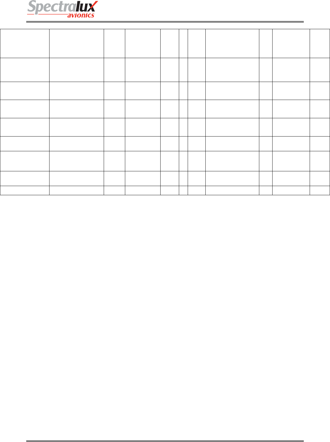
Figure 3.11.1-1 Software Versions Menu 1
P/N Part number of the Dlink+ /w CPDLC
SBC VER Version number for the Single Board Computer application
IO VER Version number for the Input Output application and FPGA
DU VER Version number for the Display Unit application and FPGA
M0 VER Version number for the Mode 0 VDL application and FPGA
M2 VER Version number for the Mode 2 VDL application
CFG PART NO Customer specific part number for the configuration
CORE DB VER Internal tracking information.
<RETURN Return to previous page
Dlink+CPDLC Users Guide
Document Number: UG-14114 Rev. - Page 55 of 201
3.11.2 User Edit – Software Versions Menu Page 2
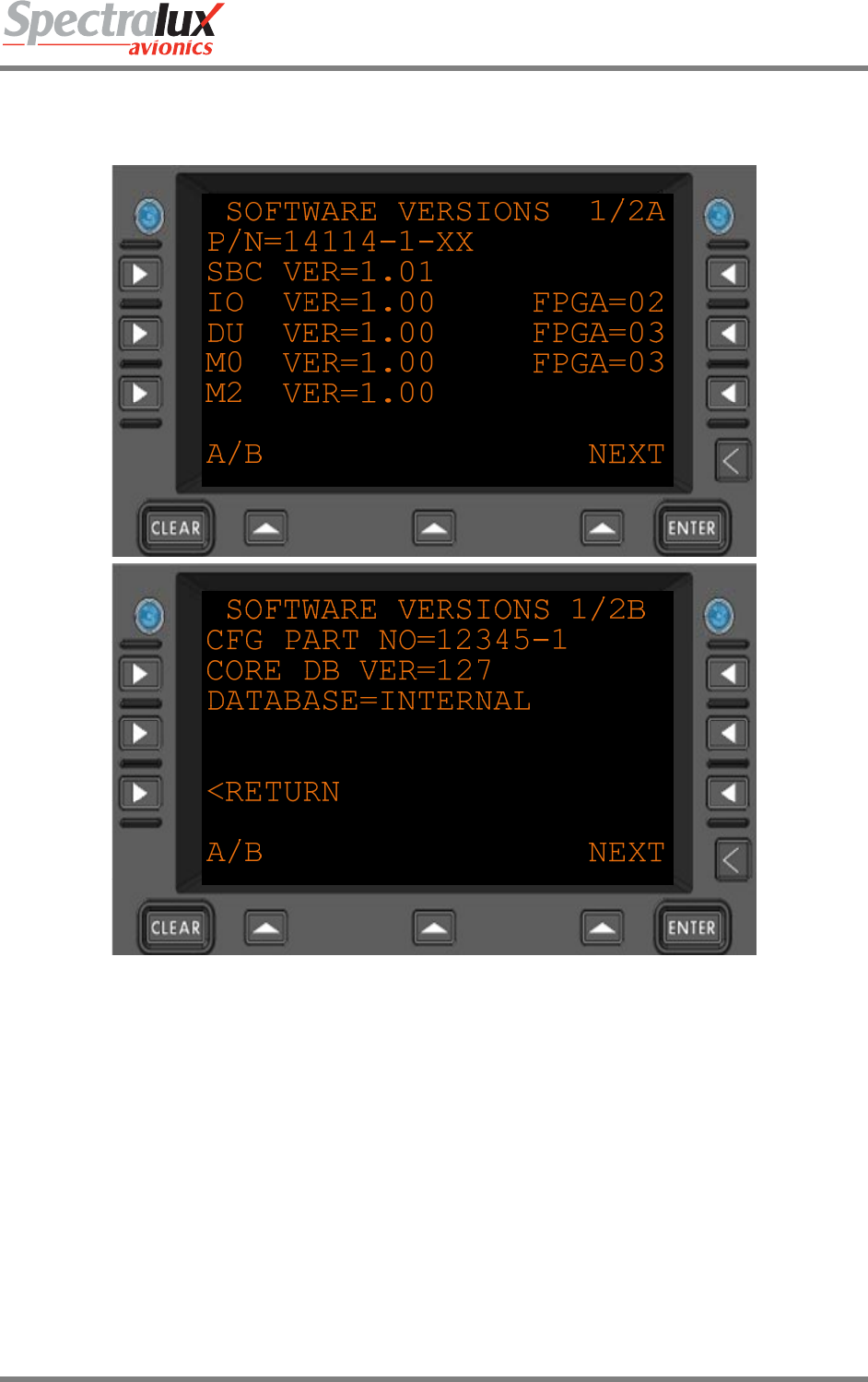
Figure 3.11.2-1 Software Versions Menu 2
SBC CRC Unique application image check data
IO CRC Unique application image check data
DU CRC Unique application image check data
MO CRC Unique application image check data
M2 CRC Unique application image check data
<RETURN Return to previous page
Dlink+CPDLC Users Guide
Document Number: UG-14114 Rev. - Page 56 of 201
3.12 System Edit Menu
3.12.1 System Edit – System Configuration Menu Page 1
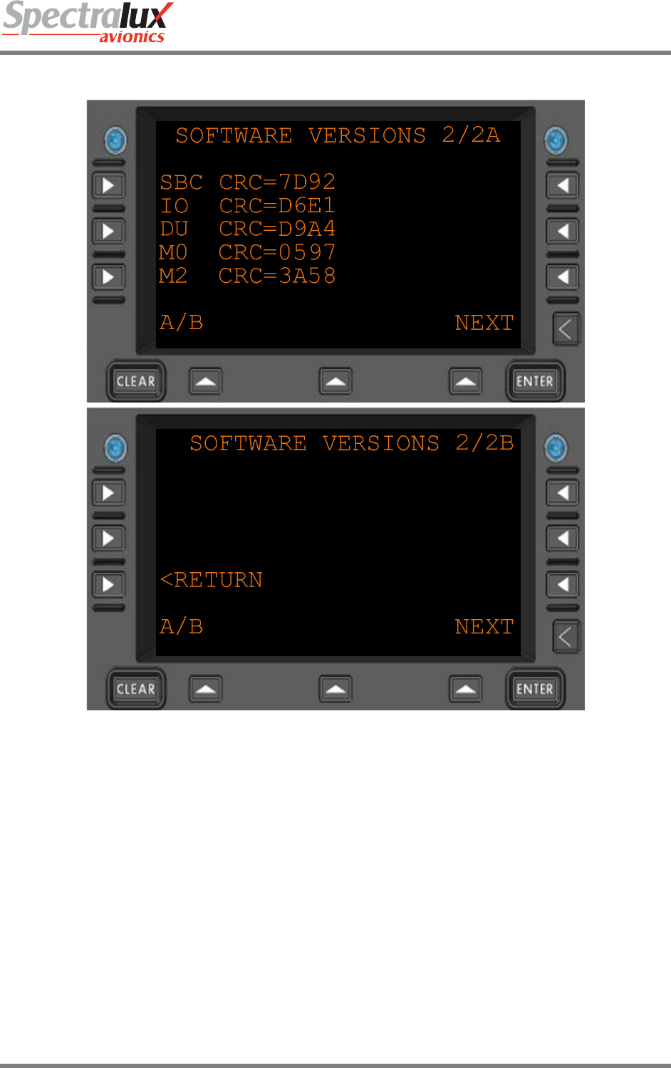
Figure 3.12.1-1 System Configuration Menu 1
IO PCA IP
ADDRESS
Internal address for the Input Output circuit assembly
DU PCA IP
ADDRESS
Internal address for the Display Unit circuit assembly
HPI DRIVER
(HI HO
TYPE)
Driver information for the internal radio bus.
Dlink+CPDLC Users Guide
Document Number: UG-14114 Rev. - Page 57 of 201
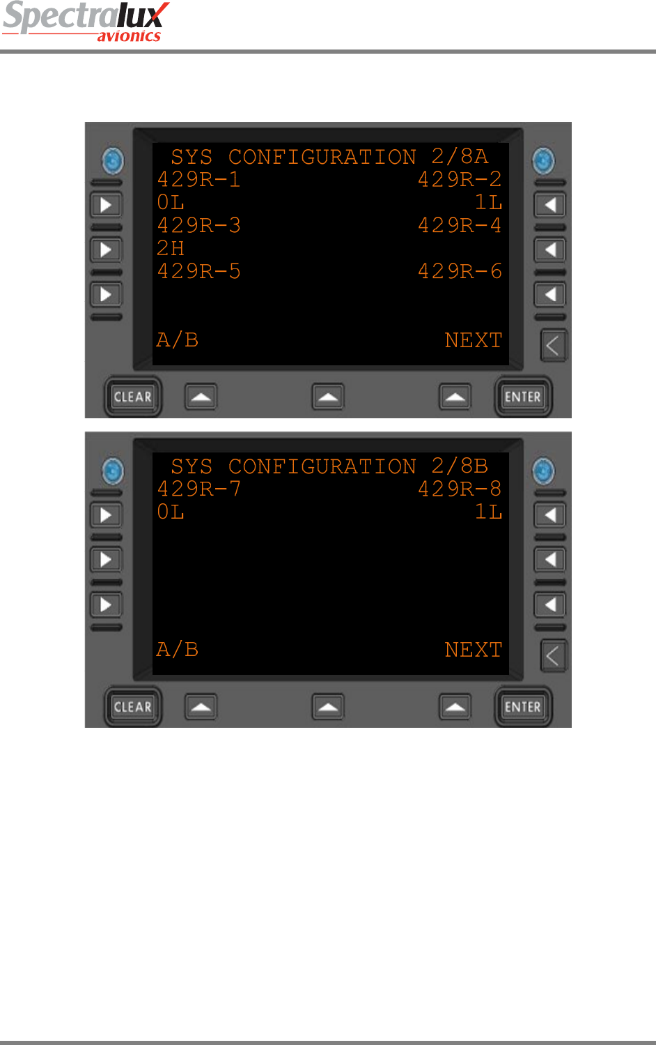
3.12.2 System Edit – System Configuration Menu Page 2
Figure 3.12.2-1 System Configuration Menu 2
429R-n Software configuration for the ARINC 429 receiver ports 1 - 8
H – High speed
L – Low speed
Details are beyond the scope of this document. Please contact an
authorized Spectralux maintenance representative for more information.
Dlink+CPDLC Users Guide
Document Number: UG-14114 Rev. - Page 58 of 201
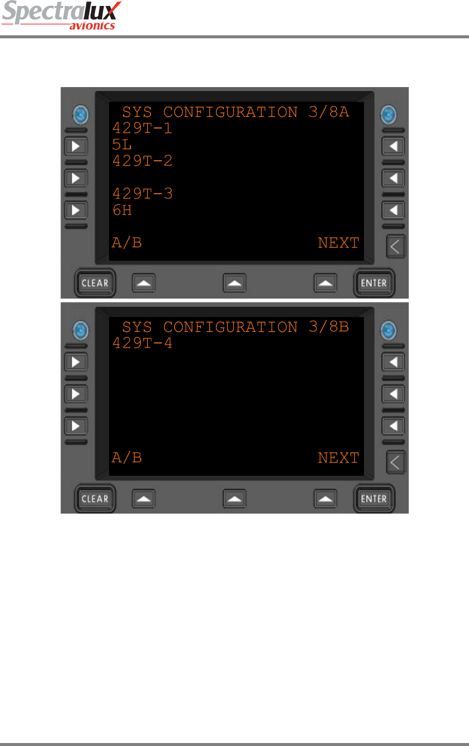
3.12.3 System Edit – System Configuration Menu Page 3
Figure 3.12.3-1 System Configuration Menu 3
429T-n Software configuration for the ARINC 429 transmitter ports 1 - 4.
H – High speed
L – Low speed
Details are beyond the scope of this document. Please contact an
authorized Spectralux maintenance representative for more information.
Dlink+CPDLC Users Guide
Document Number: UG-14114 Rev. - Page 59 of 201
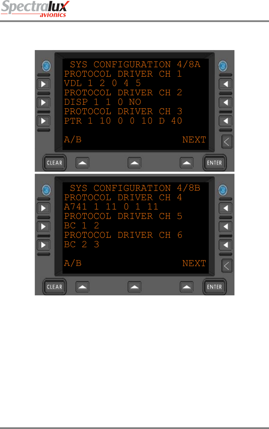
3.12.4 System Edit – System Configuration Menu Page 4
Figure 3.12.4-1 System Configuration Menu 4
Configuration information for the various installed systems.
Details are beyond the scope of this document. Please contact an
authorized Spectralux maintenance representative for more information.
Dlink+CPDLC Users Guide
Document Number: UG-14114 Rev. - Page 60 of 201
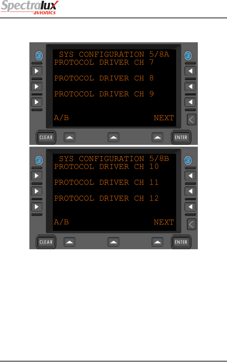
3.12.5 System Edit – System Configuration Menu Page 5
Figure 3.12.5-1 System Configuration Menu 5
Configuration information for the various installed systems.
Details are beyond the scope of this document. Please contact an
authorized Spectralux maintenance representative for more information.
Dlink+CPDLC Users Guide
Document Number: UG-14114 Rev. - Page 61 of 201
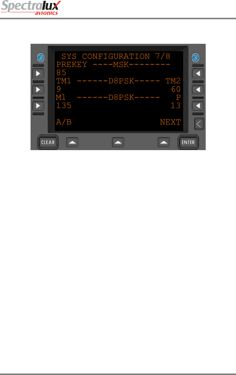
3.12.6 System Edit – System Configuration Menu Page 6
Figure 3.12.6-1 System Configuration Menu 6
Configuration information for the various installed systems.
Details are beyond the scope of this document. Please contact an
authorized Spectralux maintenance representative for more information.
Dlink+CPDLC Users Guide
Document Number: UG-14114 Rev. - Page 62 of 201
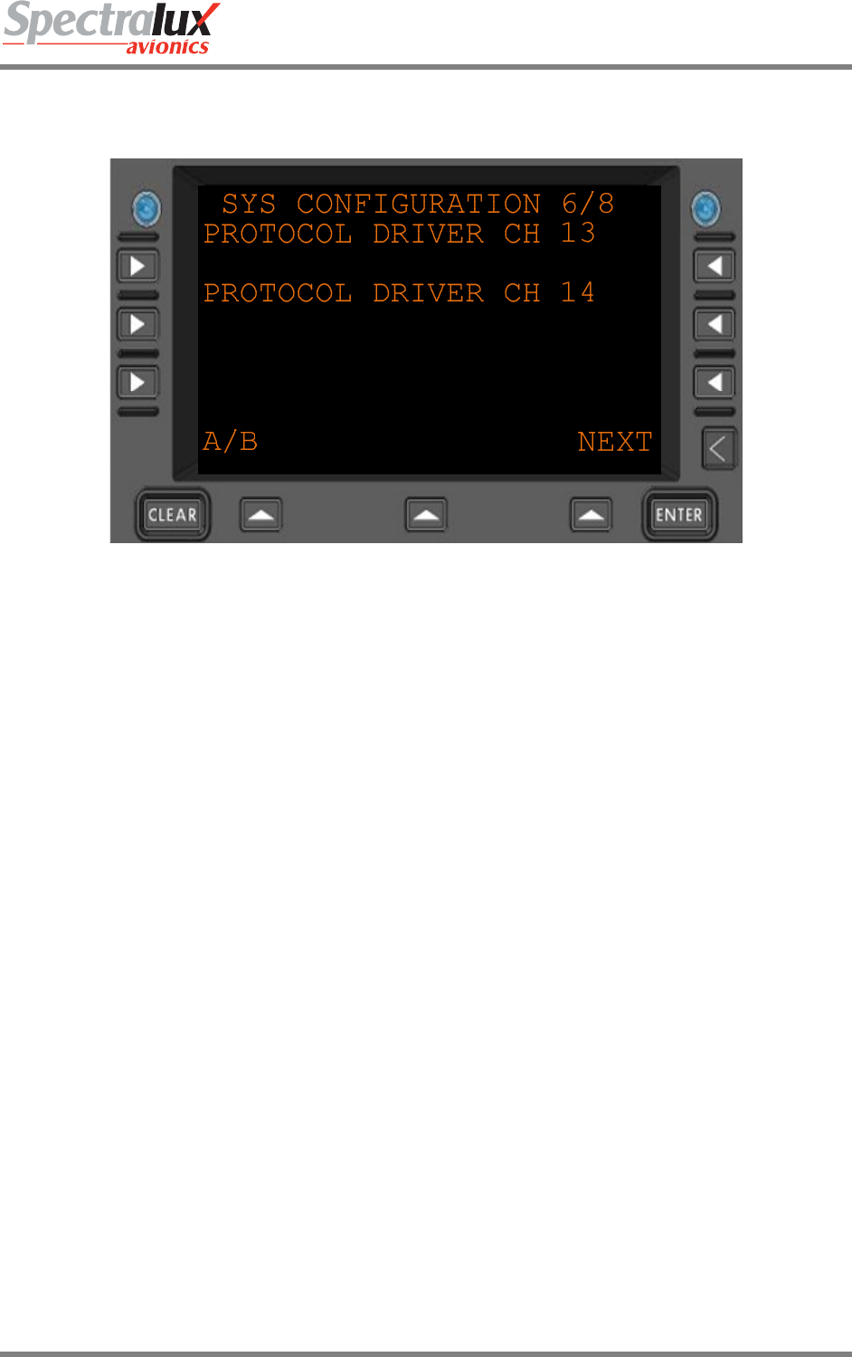
3.12.7 System Edit – System Configuration Menu Page 7
Figure 3.12.7-1 System Configuration Menu 7
Configuration information for the various installed systems.
Details are beyond the scope of this document. Please contact an
authorized Spectralux maintenance representative for more information.
Dlink+CPDLC Users Guide
Document Number: UG-14114 Rev. - Page 63 of 201
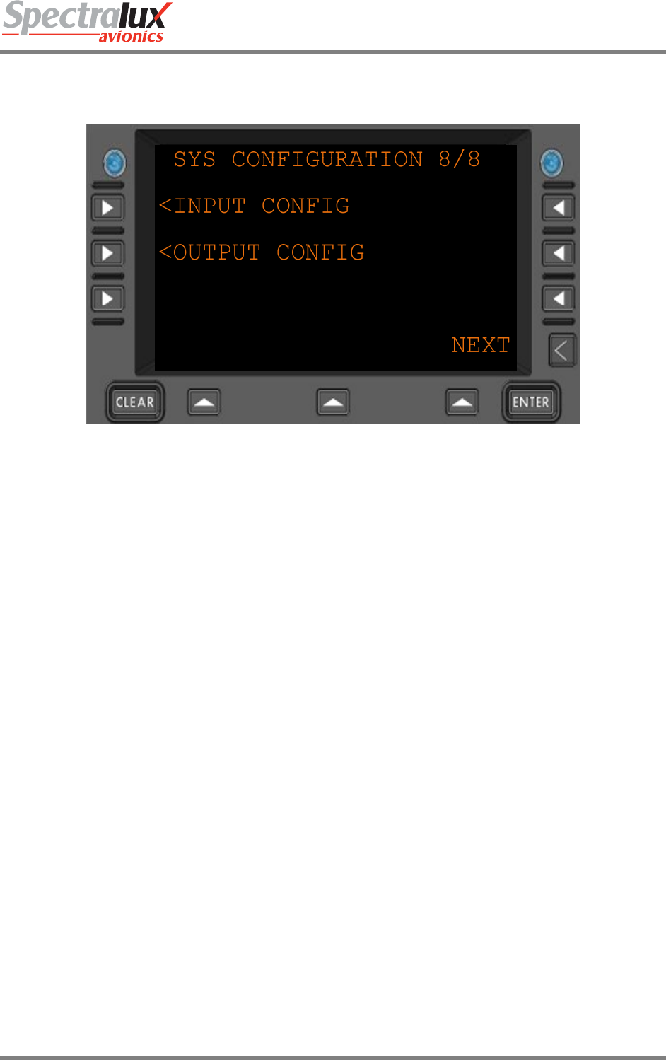
3.12.8 System Edit – System Configuration Menu Page 8
Figure 3.12.8-1 System Configuration Menu 8
<INPUT
CONFIG
Navigate to the Input Configuration menu
<OUTPUT
CONFIG
Navigate to the Output Configuration menu
Dlink+CPDLC Users Guide
Document Number: UG-14114 Rev. - Page 64 of 201
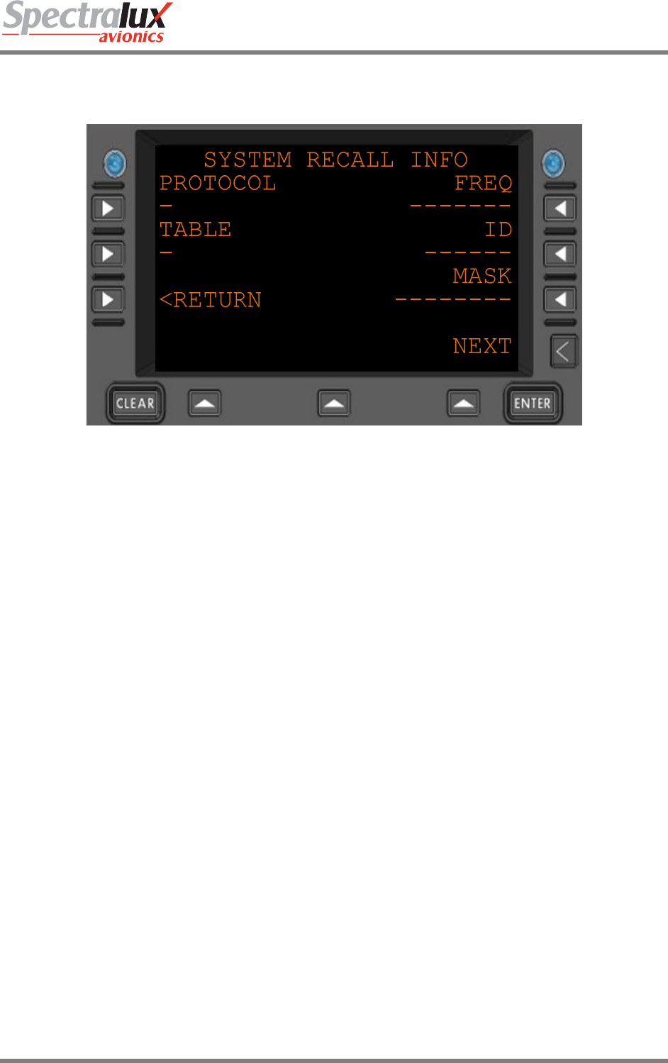
3.12.9 System Edit – System Recall Information Menu
Figure 3.12.9-1 System Recall Information Menu
PROTOCOL What was the last protocol successfully used
TABLE Details used to recognize ground system
FREQ Last frequency successfully used
ID Details used to recognize ground system
MASK Details used to recognize ground system
<RETURN Return to previous page
Dlink+CPDLC Users Guide
Document Number: UG-14114 Rev. - Page 65 of 201
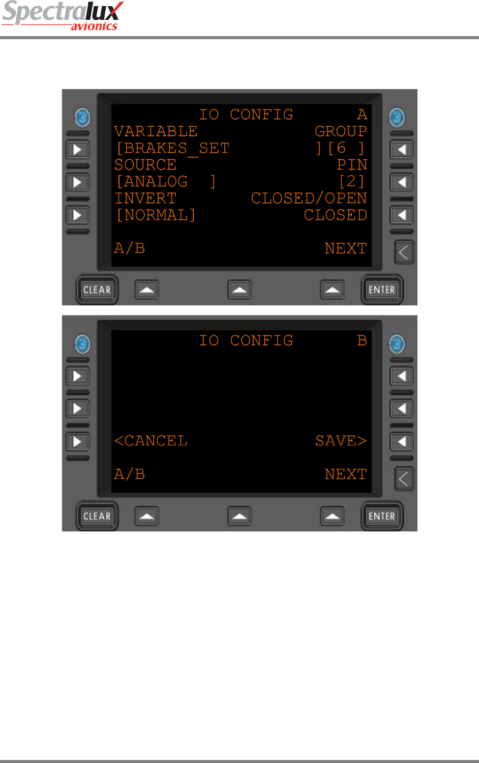
3.12.10 System Edit – Analog Input Discrete Configuration Menu
Figure 3.12.10-1 IO Configuration Menu – Analog Discrete
GROUP Category from which to collect the variable from
VARIABLE Specific data item to configure
SOURCE The Analog discrete input is selected as the source.
PIN Which analog discrete input pin to use as input.
INVERT Change the ‘sense’ of the input; (NORMAL, INVERT) IF the OPEN/CLOSED
indication is contrary to what is known, change the sense.
CLOSED/OPEN Reflecting the current logical input, taking into account the INVERT option.
<CANCEL Return to previous page – Do not save
SAVE> Save the changes. Will cause the Dlink+ w/CPDLC to reboot after saving.
Dlink+CPDLC Users Guide
Document Number: UG-14114 Rev. - Page 66 of 201
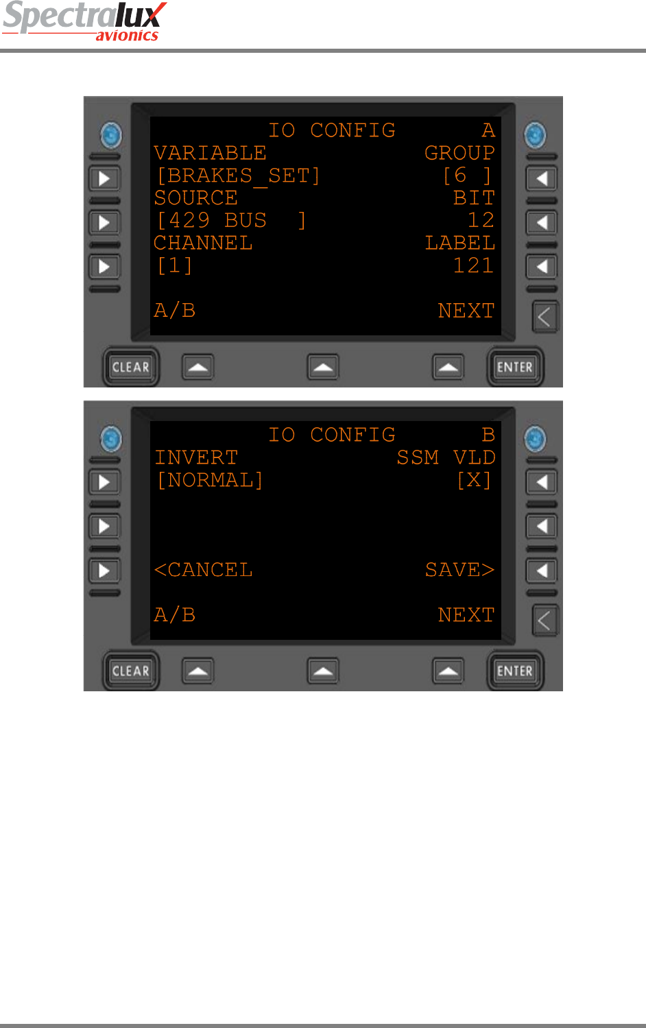
3.12.11 System Edit – Digital Input Discrete Configuration Menu
Figure 3.12.11-1 IO Configuration Menu – Digital Discrete
GROUP Category from which to collect the variable from
VARIABLE Specific data item to configure
SOURCE The ARINC 429 input is selected as the source.
BIT Which bit in the ARINC 429 to use.
LABEL Which ARINC 429 label to use.
CHANNEL Which ARINC 429 receiver to use.
INVERT Change the ‘sense’ of the input; (NORMAL, INVERT) IF the OPEN/CLOSED
indication is contrary to what is known, change the sense.
SSM VLD If the in-coming discrete data validation logic shall use the SSM flags set by the
equipment.
<CANCEL Return to previous page – Do not save
SAVE> Save the changes. Will cause the Dlink+ w/CPDLC to reboot after saving.

Dlink+CPDLC Users Guide
Document Number: UG-14114 Rev. - Page 67 of 201
3.12.12 System Edit – Arinc 429 Input Configuration Menu
Figure 3.12.12-1 IO Configuration Menu – Arinc 429
GROUP Category from which to collect the variable from
VARIABLE Specific data item to configure
SOURCE The ARINC 429 input is selected as the source.
BIT Which bit in the ARINC 429 to use.
LABEL Which ARINC 429 label to use.
CHANNEL Which ARINC 429 receiver to use.
SSM VLD If the in-coming discrete data validation logic shall use the SSM flags set by the
equipment.
<CANCEL Return to previous page – Do not save
SAVE> Save the changes. Will cause the Dlink+ w/CPDLC to reboot after saving.
Dlink+CPDLC Users Guide
Document Number: UG-14114 Rev. - Page 68 of 201
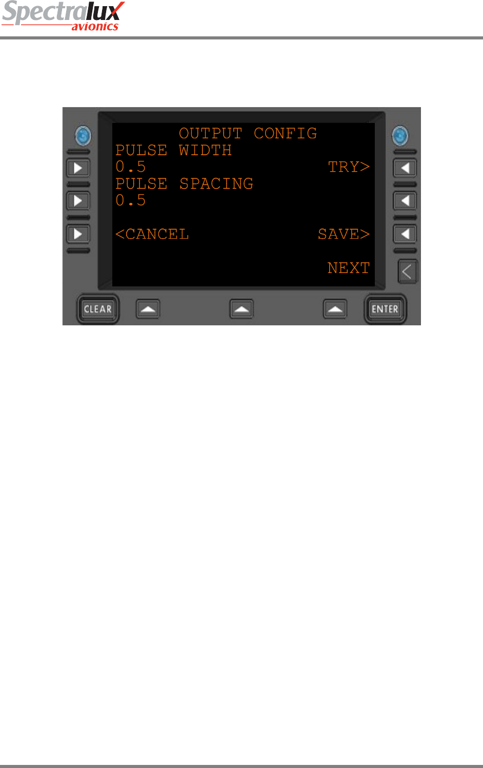
3.12.13 System Edit – Output Configuration Menu
Figure 3.12.13-1 Output Configuration
PULSE WIDTH Restricted to a float number between .1 second and 10.0 seconds
PULSE SPACING Restricted to a float number between .1 second and 10.0 seconds
TRY> The ARINC 429 input is selected as the source.
<CANCEL Return to previous page – Do not save
SAVE> Save the changes. Will cause the Dlink+ w/CPDLC to reboot after saving.
Dlink+CPDLC Users Guide
Document Number: UG-14114 Rev. - Page 69 of 201
4 ACARS Menus
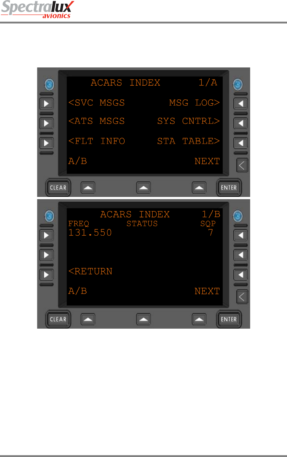
4.1 ACARS Index Menu
Figure 3.12.13-1 ACARS Index Menu
<SVC MSGS Navigate to the Service Messages Menu
<ATS MSGS Navigate to the ATS Messages Menu
<FLT INFO Navigate to the Flight Info Menu
MSG LOG> Navigate to the Message Log Menu
SYS CNTRL> Navigate to the System Control Messages Menu
STA TABLE> Navigate to the Station Table Menu
FREQ The current frequency
STATUS The current radio status
SQP The current Signal Quality Parameter, VHF signal strength
<RETURN Return to previous page
Dlink+CPDLC Users Guide
Document Number: UG-14114 Rev. - Page 70 of 201
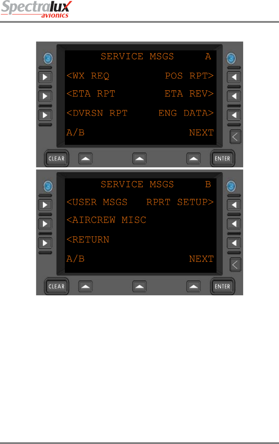
4.1.1 ACARS Index – Service Messages Menu
Figure 4.1.1-1 Service Messages Menu
<WX REQ Navigate to the Weather Request Menu
<ETA RPT Navigate to the ETA Report Menu
<DVRSN RPT Navigate to the Diversion Report Menu
<USER MSGS Navigate to the User Messages Menu
<AIRCREW MISC Navigate to the Aircrew Miscellaneous Menu
POS RPT> Navigate to the Position Report Menu
ETA REV> Navigate to the ETA Revision Menu
ENG DATA> Navigate to the Engine Data Menu
RPRT SETUP> Navigate to the Report Setup Menu
<RETURN Return to previous page

Dlink+CPDLC Users Guide
Document Number: UG-14114 Rev. - Page 71 of 201
4.1.2 ACARS Index – ATS Requests Menu
Figure 4.1.2-1 ATS Messages Menu
<ATIS REQ Navigate to the ATIS Request Menu
<CLEARANCE REQ Navigate to the Clearance Request Menu
TWIP> Navigate to the TWIP Menu
FREE TEXT> Navigate to the Free Text Menu
<RETURN Return to previous page
Dlink+CPDLC Users Guide
Document Number: UG-14114 Rev. - Page 72 of 201
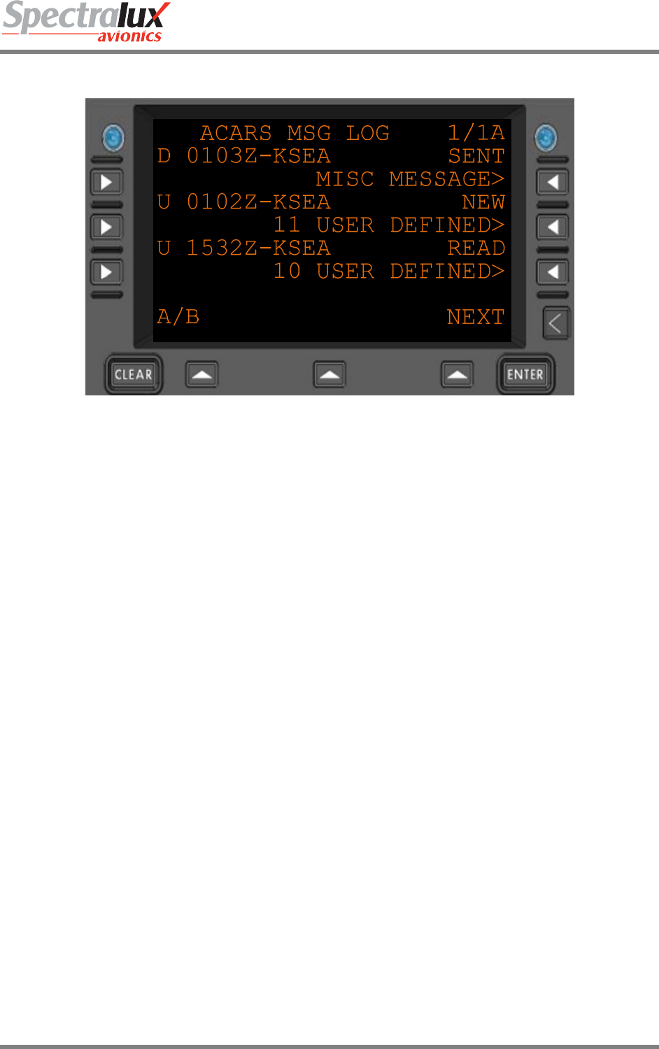
4.1.3 ACARS Index – Message Log Menu
Figure 4.1.3-1 ACARS Message Log Menu
D or U Uplink or Downlink
0103Z Time referenced to Zulu when the message was sent or received.
Varies with each message
SENT
NEW
READ
Status of the message.
Will change from NEW to READ after viewing.
10 USER DEFINED> Navigate to menu to display message. Text varies with message
Dlink+CPDLC Users Guide
Document Number: UG-14114 Rev. - Page 73 of 201
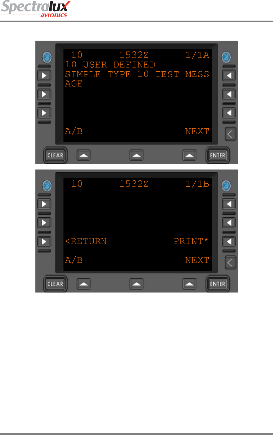
4.1.3.1 ACARS Index – Message Log Viewing Menu
Figure 4.1.3-2 ACARS Message Log - View Message
10 Label associated with message
1532Z Time referenced to Zulu when the message was sent or received.
Varies with each message
Message text.
Varies
PRINT* Send the message to the printer.
<RETURN Return to previous page

Dlink+CPDLC Users Guide
Document Number: UG-14114 Rev. - Page 74 of 201
4.1.4 ACARS Index – System Control Messages Menu
See Section System Control Messages Menu
Dlink+CPDLC Users Guide
Document Number: UG-14114 Rev. - Page 75 of 201
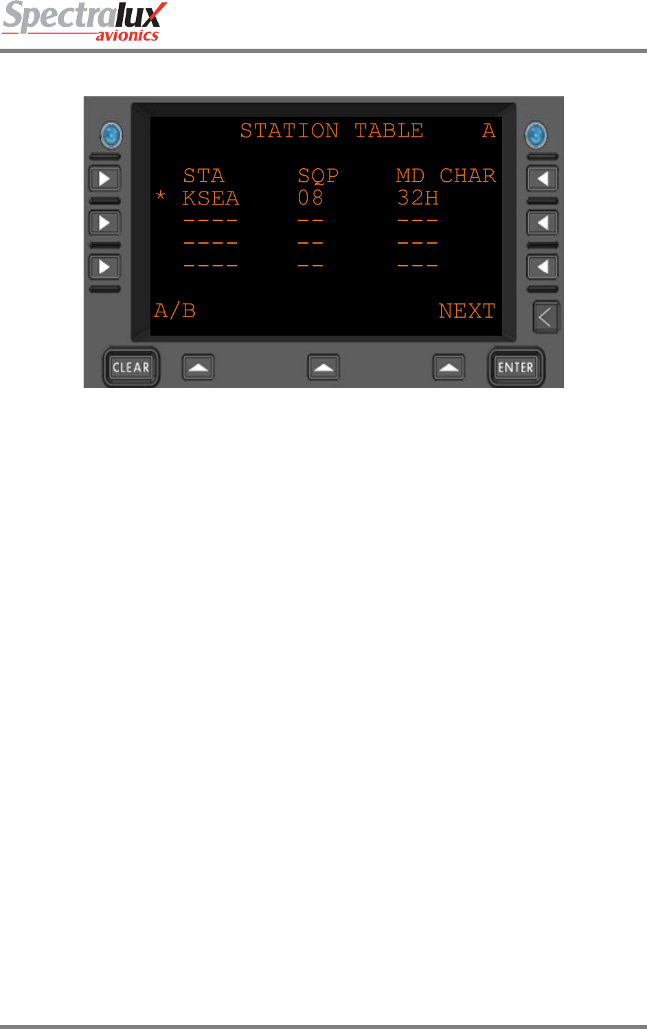
4.1.5 ACARS Index – Station Table POA Stations Menu
Figure 4.1.5-1 Station Table Menu
STA Station identifier
* The asterisk signifies which is the currently linked station
SQP Signal Quality Parameter – VHF signal strength
MD CHAR The Mode char
Dlink+CPDLC Users Guide
Document Number: UG-14114 Rev. - Page 76 of 201
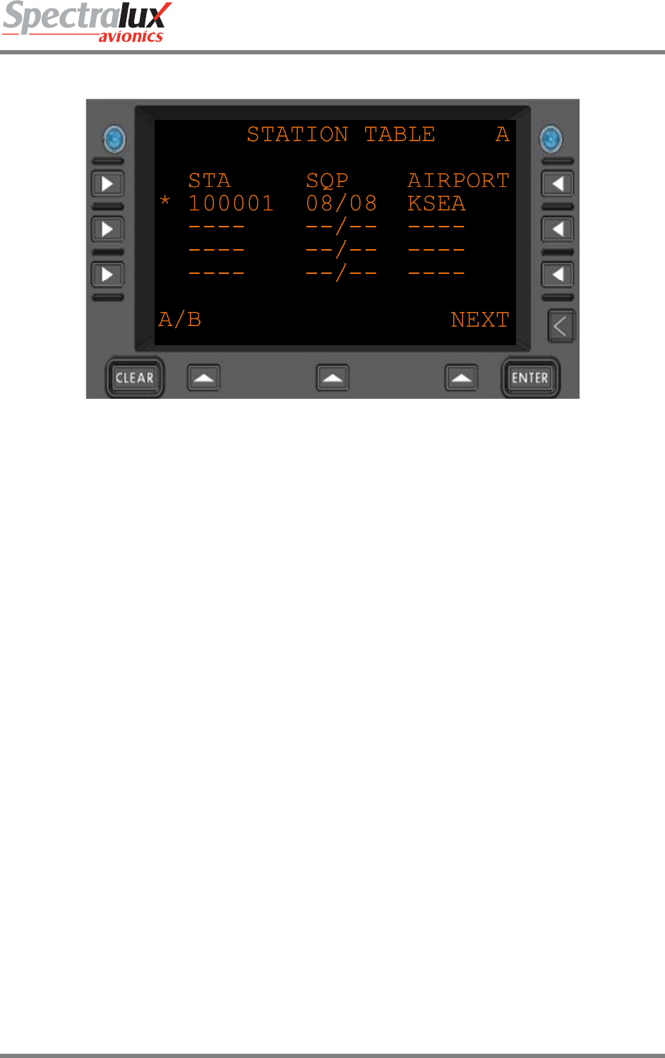
4.1.6 ACARS Index – Station Table AOA Stations Menu
Figure 4.1.6-1 Station Table AOA Stations
STA Station identifier
* The asterisk signifies which is the currently linked station
SQP Signal Quality Parameter – VHF signal strength
AIRPORT Airport associated with the current station

Dlink+CPDLC Users Guide
Document Number: UG-14114 Rev. - Page 77 of 201
4.1.7 ACARS Index – Flight Information Menu
See Main –
Dlink+CPDLC Users Guide
Document Number: UG-14114 Rev. - Page 78 of 201
4.2 ACARS Service Messages Menus
4.2.1 ACARS Service Messages – Weather Request Menu
WEATHER REQUEST
FREE TEXT
------------------------
<RETURN SEND*
A/B NEXT
Figure 4.2.1-1 Weather Request Menu
FREE TEXT Free text to be sent with the Weather request
SEND* After free text has been entered the SEND prompt will allow it to be sent.
<RETURN Return to previous page

Dlink+CPDLC Users Guide
Document Number: UG-14114 Rev. - Page 79 of 201
4.2.2 ACARS Service Messages – Estimated Time of Arrival Report Menu
ETA REPORT A
DEST STA ETA
LAX 1430
FUEL ON BOARD
4370
FREE TEXT
------------------------
A/B NEXT
ETA REPORT B
<RETURN SEND*
A/B NEXT
Figure 4.2.2-1 ETA Report Menu
DEST STA Destination station (AAA)
ETA Estimated Time of Arrival (HHMM)
FUEL ON BOARD Current fuel on board (ZZZZ)
FREE TEXT Up to 24 characters of free text to be sent with the message
SEND* When the DEST STA, ETA, and FUEL ON BOARD have been filled in the SEND
prompt will appear.
<RETURN Return to previous page
Dlink+CPDLC Users Guide
Document Number: UG-14114 Rev. - Page 80 of 201
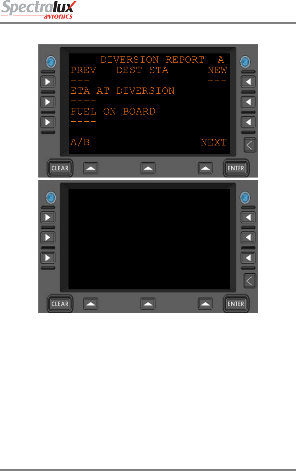
4.2.3 ACARS Service Messages – Diversion Report Menu
DIVERSION REPORT B
ORIGINATING STATION
---
FREE TEXT
------------------------
<RETURN SEND*
A/B NEXT
Figure 4.2.3-1 Diversion Report menu
PREV The previous destination station. (AAA) 3 alpha-numeric characters
NEW The new destination station. (AAA) 3 alpha-numeric characters
ETA AT DIVERSION Estimated Time of Arrival at the new destination station (HHMM)
FUEL ON BOARD Current quantity of fuel on board (ZZZZ) 4 digits, zero filled
ORIGINATING
STATION
The originating station; take off (AAA) 3 alpha-numeric characters
FREE TEXT Up to 24 characters of free text
SEND* When the data items are filled in satisfactorily the SEND prompt will appear
<RETURN Return to previous page
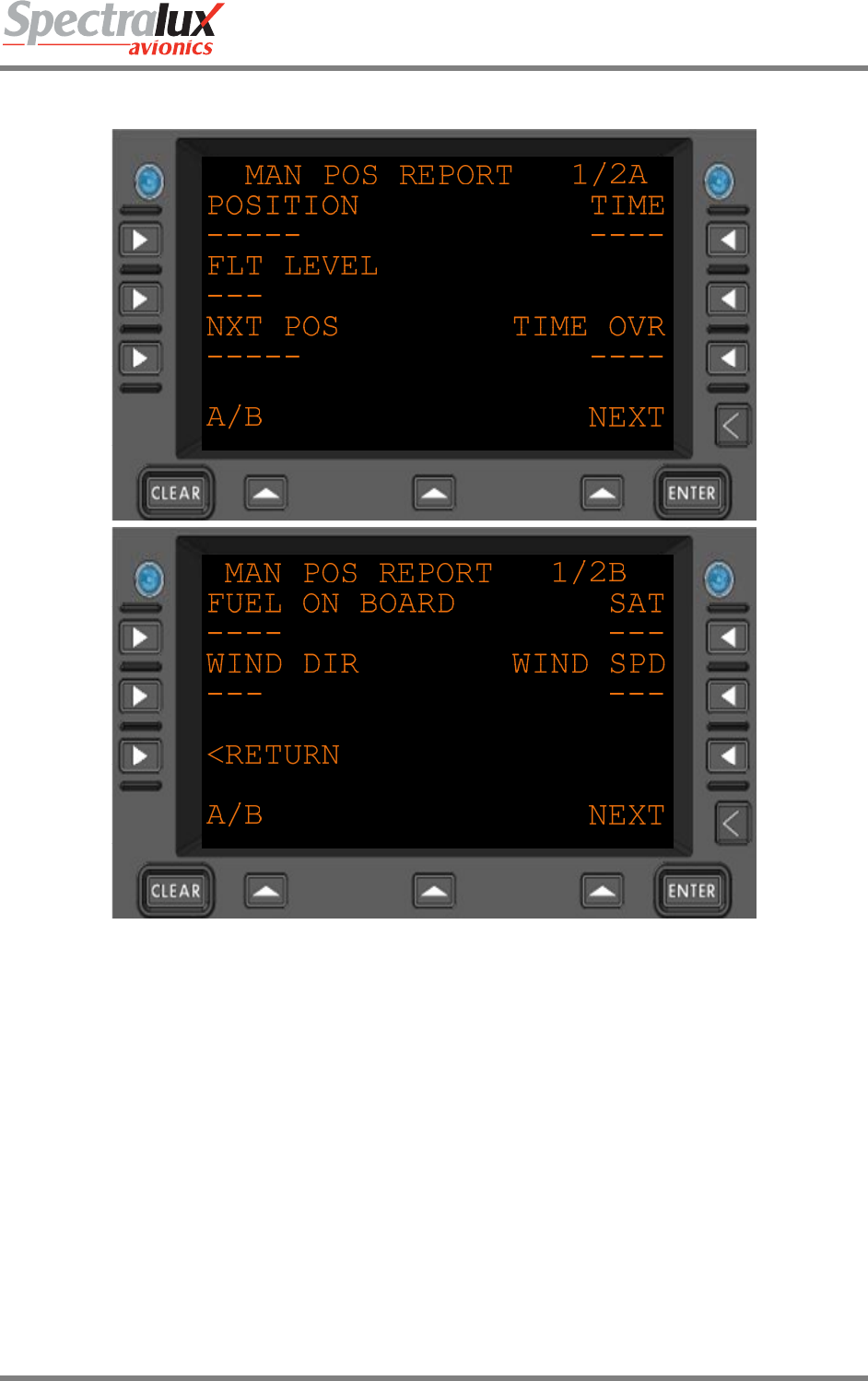
Dlink+CPDLC Users Guide
Document Number: UG-14114 Rev. - Page 81 of 201
4.2.4 ACARS Service Messages – Position Report Menu Page 1
Figure 4.2.4-1 Manual Position Report Menu 1
POSITION Current position. 1-5 alpha-numeric characters. May be a 3 character radio NAVID
FLT LEVEL The current altitude. 3 digits zero-filled. Generally collected from 429 data.
NXT POS Next position. 1-5 alpha-numeric characters. May be a 3 character radio NAVID
TIME Current UTC (HHMM)
TIME OVR Time estimated at Next Position ( HHMM)
FUEL ON BOARD Current fuel on board (ZZZZ)
SAT Static Air Temperature (SNN) Where:
"S" is "+" or " –".
"NN" represents a 2 digit Temperature in Celsius, zero filled.
WIND DIR Wind Direction (NNN) zero filled [000-359]
WIND SPD Wind Speed (NNN) zero filled [000-999]
<RETURN Return to previous page
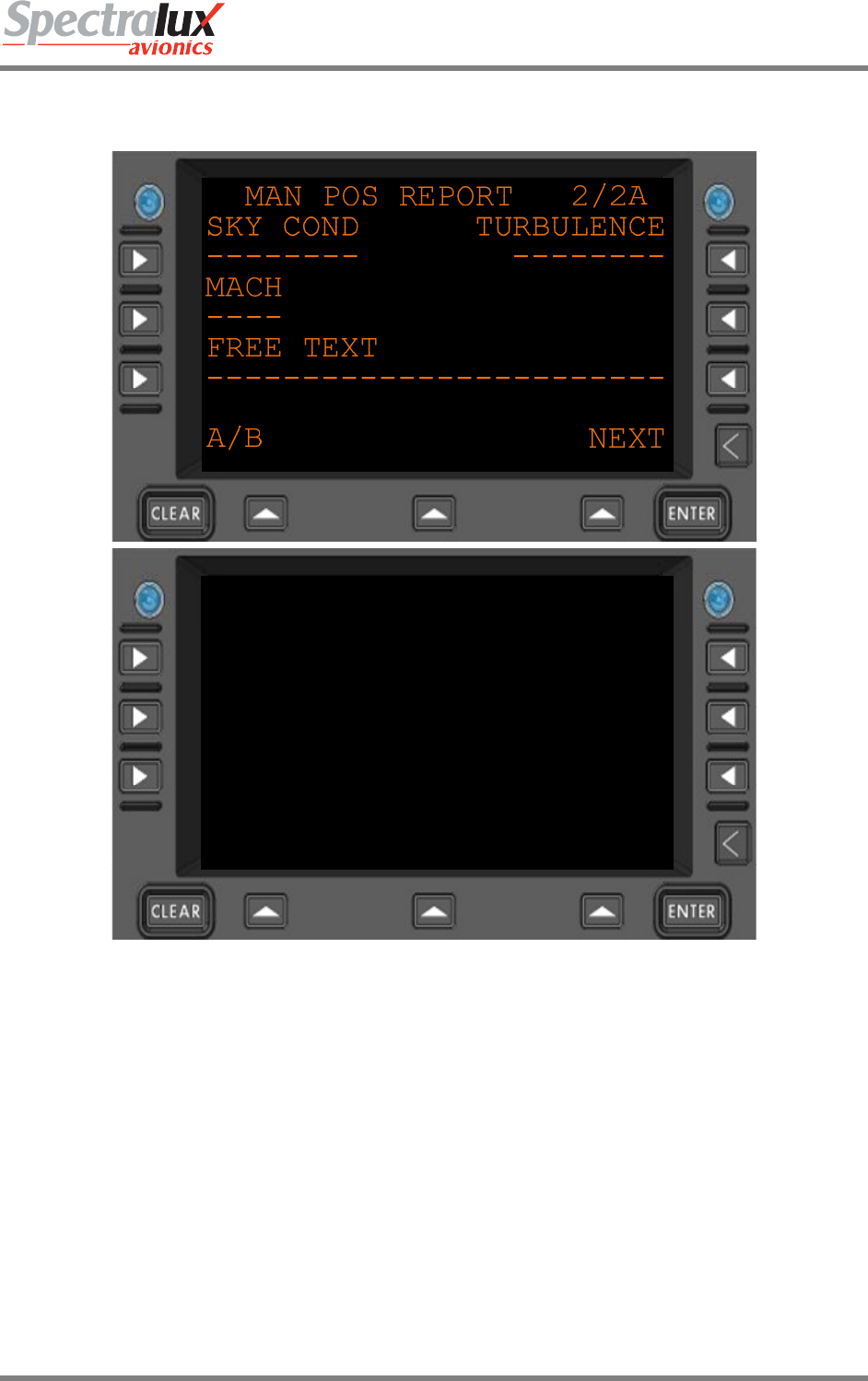
Dlink+CPDLC Users Guide
Document Number: UG-14114 Rev. - Page 82 of 201
4.2.5 ACARS Service Messages – Position Report Menu Page 2
MAN POS REPORT 2/2B
<RETURN SEND*
A/B NEXT
Figure 4.2.5-1 Manual Position Report Menu 2
SKY COND Sky condition (AAAAAAAA). Ex: CLEAR, OVERCAST.
TURBULENCE Turbulence (AAAAAAAA). Ex: LIGHT, MODERATE, SEVERE
MACH The current mach speed of the aircraft (N.NN)
FREE TEXT Up to 24 characters of free text
SEND* If Pilot-entered and system data is compiled and formatted the SEND prompt will
appear.
<RETURN Return to previous page
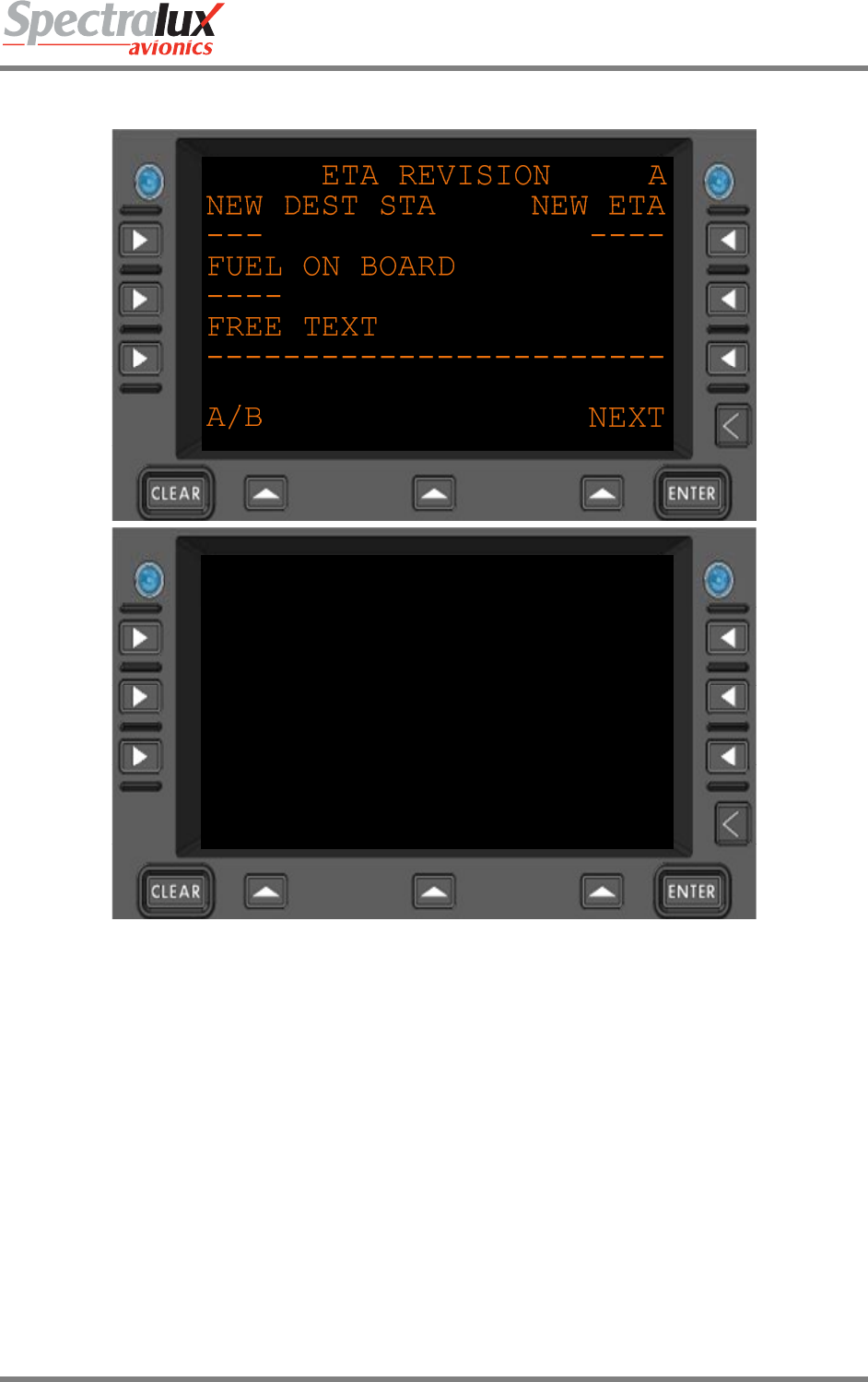
Dlink+CPDLC Users Guide
Document Number: UG-14114 Rev. - Page 83 of 201
4.2.6 ACARS Service Messages – Estimated Time of Arrival Revision Menu
ETA REVISION B
<RETURN SEND*
A/B NEXT
Figure 4.2.6-1 ETA Revision Menu
NEW DEST STA New Destination Station (AAA)
NEW ETA New Estimated Time of Arrival (HHMM)
FUEL ON BOARD Current fuel on board (ZZZZ)
FREE TEXT Up to 24 characters of free text
SEND* If Pilot-entered and system data is compiled and formatted the SEND prompt will
appear.
<RETURN Return to previous page

Dlink+CPDLC Users Guide
Document Number: UG-14114 Rev. - Page 84 of 201
4.2.7 ACARS Service Messages – Engine Data Menu
ENGINE DATA
FREE TEXT
------------------------
<RETURN SEND*
NEXT
Figure 4.2.7-1 Engine Data Menu
FREE TEXT Up to 24 characters of free text
SEND* If Pilot-entered data is compiled and formatted the SEND prompt will
appear.
<RETURN Return to previous page
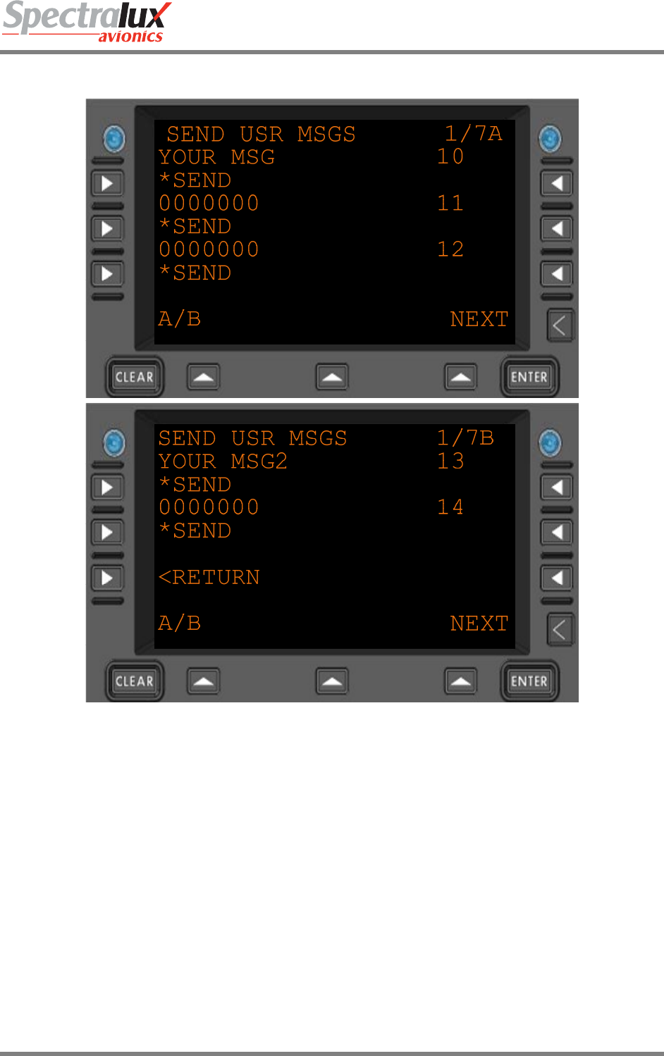
Dlink+CPDLC Users Guide
Document Number: UG-14114 Rev. - Page 85 of 201
4.2.8 ACARS Service Messages – User Messages Menu
Figure 4.2.8-1 Send User Messages Menu
YOUR MSG Title of User Defined Message.
Example of “YOUR MSG” shown
0000000 Title, and content to be sent, for an undefined user message
*SEND Send the associated User Defined Message
10
11
…
49
The label of the User Defined Message.
The range is from 10-49.
<RETURN Return to previous page
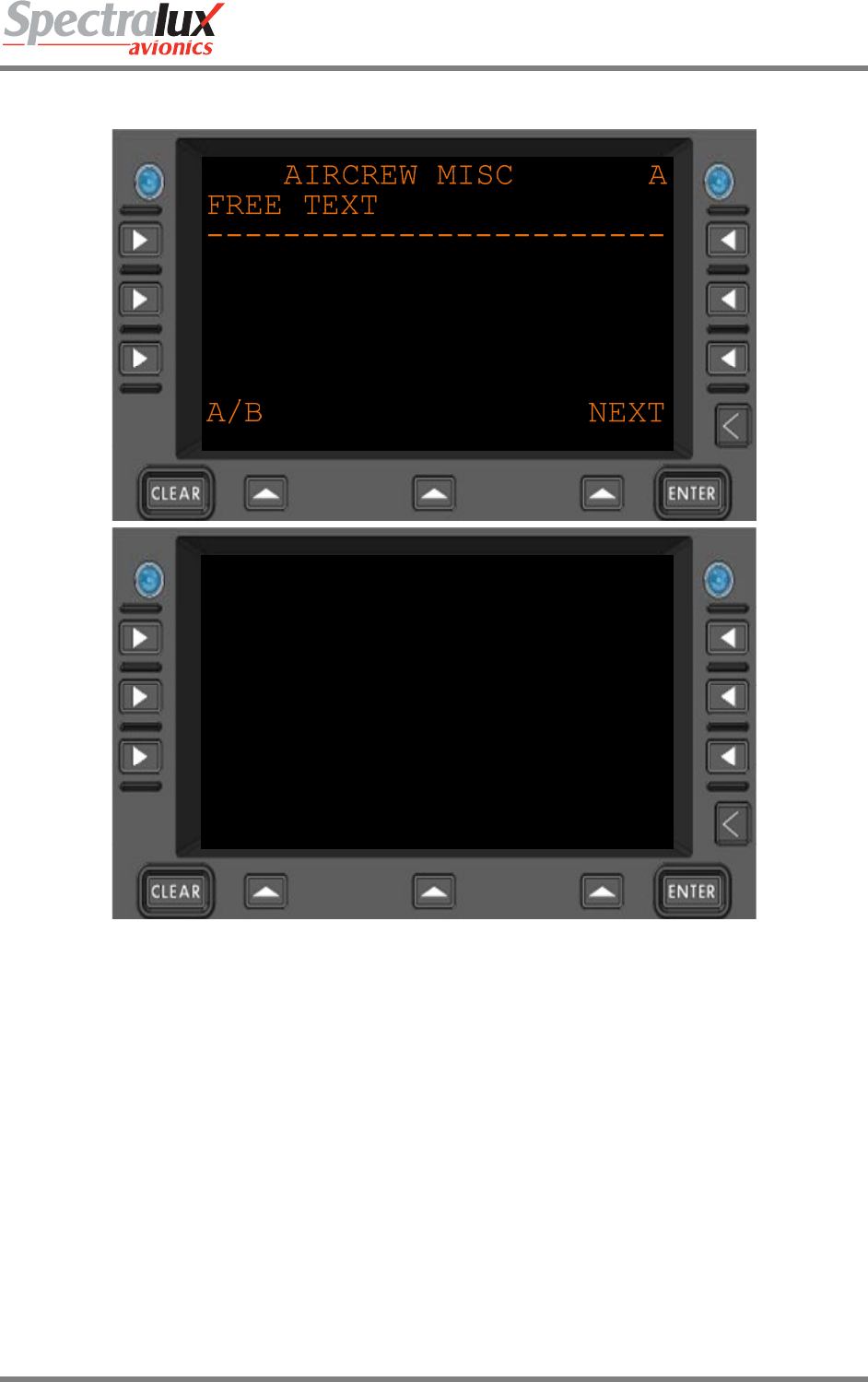
Dlink+CPDLC Users Guide
Document Number: UG-14114 Rev. - Page 86 of 201
4.2.9 ACARS Service Messages – Aircrew Miscellaneous Message Menu
AIRCREW MISC B
<RETURN SEND*
A/B NEXT
Figure 4.2.9-1 Aircrew Miscellaneous Menu
FREE TEXT Up to 24 characters of free text.
SEND* If the free text has been entered the SEND prompt will appear.
<RETURN Return to previous page
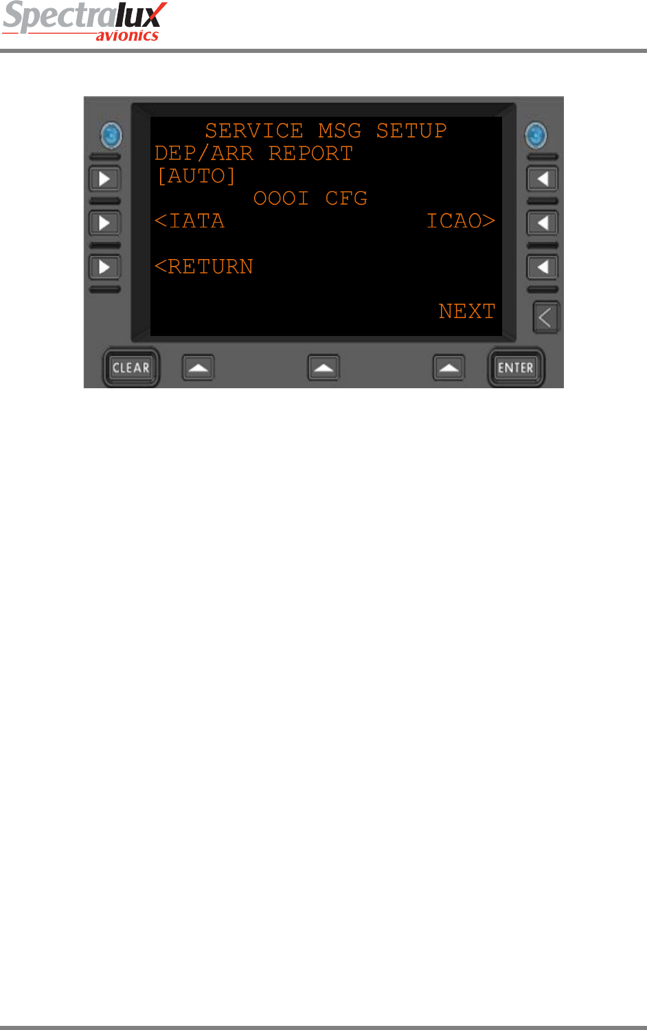
Dlink+CPDLC Users Guide
Document Number: UG-14114 Rev. - Page 87 of 201
4.2.10 ACARS Service Messages – Service Message Setup Menu
Figure 4.2.10-1 Service Message Report Setup Menu
DEP/ARR
REPORT
This configuration item controls the automatic transmission of message
Label Q1: "Departure/Arrival Report" in response to an OFF or IN Event.
Select from: [AUTO] or [OFF ]
<IATA Navigate to the IATA Service Message Setup Menu
ICAO> Navigate to the ICAO Service Message Setup Menu
<RETURN Return to previous page

Dlink+CPDLC Users Guide
Document Number: UG-14114 Rev. - Page 88 of 201
4.2.11 ACARS Service Messages – IATA Report Setup Menu Page 1
Figure 4.2.11-1 IATA Report Setup Menu 1
OUT/FUEL
REPORT
Controls the automatic transmission of message Label QA: "Out/Fuel Report" in
immediately following an OUT event.
OFF REPORT Controls the automatic transmission of message Label QB: "Off Report" in immediately
following an OFF event.
ON REPORT Controls the automatic transmission of message Label QC: "On Report" in immediately
following an ON event
IN/FUEL
REPORT
Controls the automatic transmission of message Label QD: "In Fuel Report" in immediately
following an IN event.
OUT/FUEL/DEST Controls the automatic transmission of message Label QE: "Out/Fuel/Destination Report"
in immediately following an OUT event.
OFF/DEST
REPORT
Controls the automatic transmission of message Label QF: "Off/Destination Report" in
immediately following an OFF event
All Select from: “[AUTO]” or “[OFF ]”
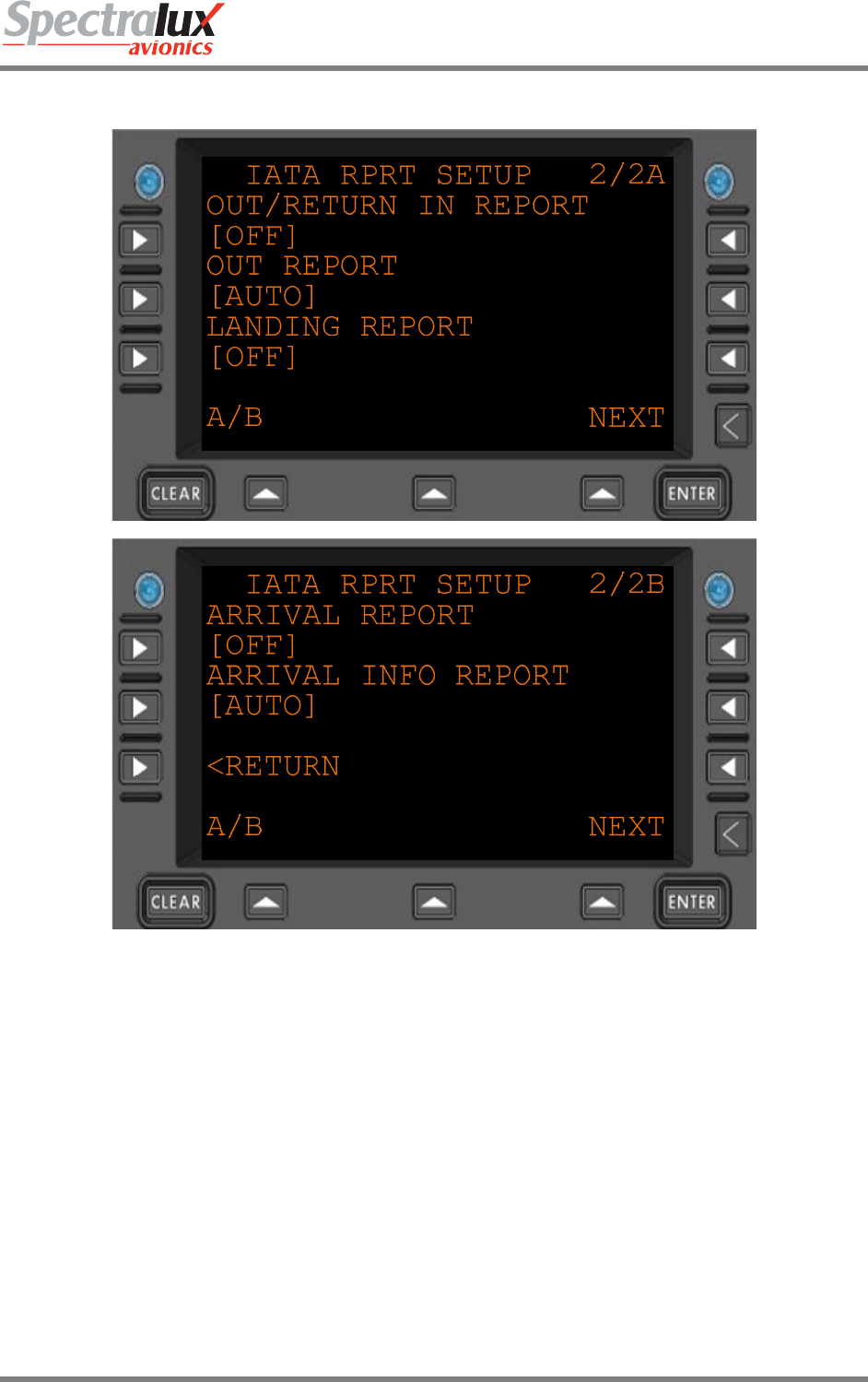
Dlink+CPDLC Users Guide
Document Number: UG-14114 Rev. - Page 89 of 201
4.2.12 ACARS Service Messages – IATA Report Setup Menu Page 2
Figure 4.2.12-1 IATA Report Setup Menu Page 2
OUT/RETURN IN
REPORT
Controls the automatic transmission of message Label QG: "Out/Return In
Report" when an aircraft returns to the gate after an OUT event.
OUT REPORT Controls the automatic transmission of message Label QH: "Out Report"
immediately following an OUT event.
LANDING REPORT Controls the automatic transmission of message Label QK: "Landing Report"
immediately following an ON event.
ARRIVAL REPORT Controls the automatic transmission of message Label QM: "Arrival
INOFRMATION Report" immediately following an IN event.
ARRIVAL INFO
REPORT
Controls the automatic transmission of a message label QM shall be sent when
an "In Event" has occurred.
<RETURN Return to previous page
All Select from: “[AUTO]” or “[OFF ]”
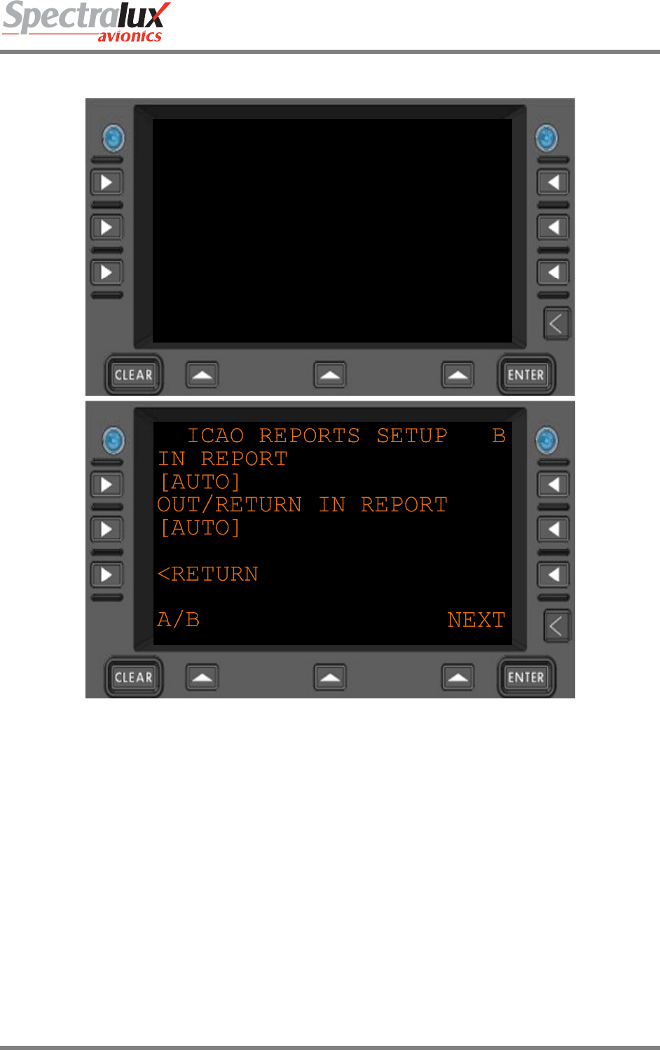
Dlink+CPDLC Users Guide
Document Number: UG-14114 Rev. - Page 90 of 201
4.2.13 ACARS Service Messages – ICAO Report Setup Menu
ICAO REPORTS SETUP A
OUT REPORT
[AUTO]
OFF REPORT
[AUTO]
ON REPORT
[AUTO]
A/B NEXT
Figure 4.2.13-1 ACARS ICAO Reports Setup Menu
OUT REPORT Controls the automatic transmission of message Label QP: "Out Report"
immediately following an OUT event.
OFF REPORT Controls the automatic transmission of message Label QQ: "Off Report" in
immediately following an OFF event.
ON REPORT Controls the automatic transmission of message Label QR: "On Report" in
immediately following an ON event.
IN REPORT Controls the automatic transmission of message Label QS: "In Report" in
immediately following an IN event.
OUT/RETURN IN
REPORT
Controls the automatic transmission of message Label QT: "Out/Return In Report"
when an aircraft returns to the gate after an OUT event.
<RETURN Return to previous page
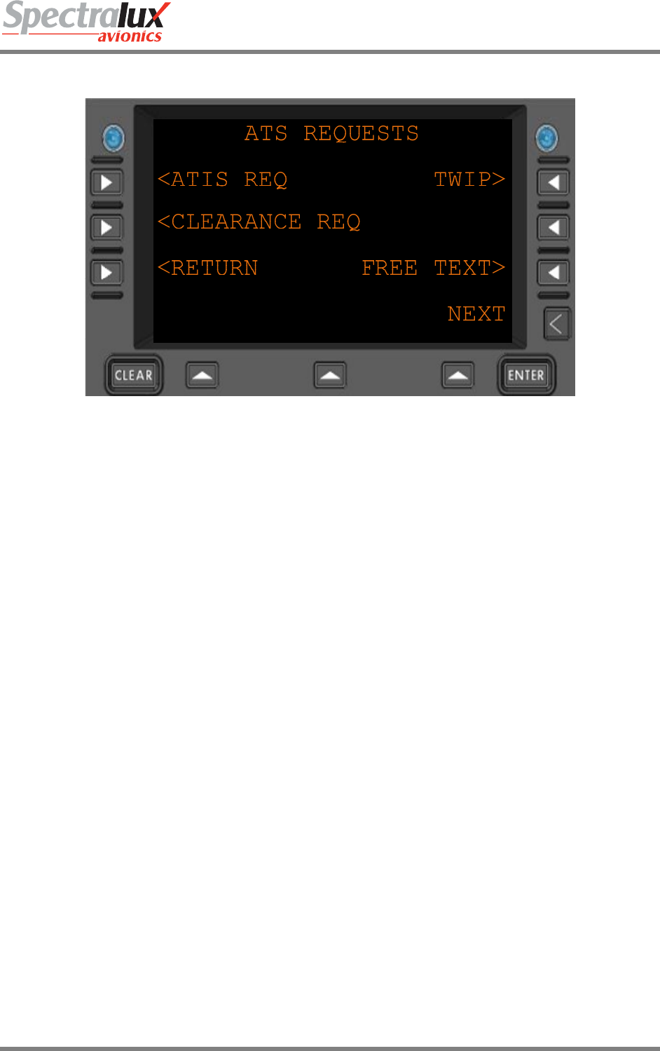
Dlink+CPDLC Users Guide
Document Number: UG-14114 Rev. - Page 91 of 201
4.3 ATS Requests Menu
Figure 4.2.13-1 ATS Requests Menu
<ATIS REQ Navigates to the ATIS Request Menu
<CLEARANCE REQ Navigates to the Clearance Request Menu
TWIP> Navigates to the TWIP Request Menu
FREE TEXT> Navigates to the Free Text Message Menu
<RETURN Return to previous page

Dlink+CPDLC Users Guide
Document Number: UG-14114 Rev. - Page 92 of 201
4.3.1 ATS Request – ATIS Report Request Menu
ATIS REPORT REQUEST
ARR/DEP IND AIRPORT
[A] ----
<RETURN SEND*
NEXT
Figure 4.3.1-1 ATIS Report Request Menu
ARR/DEP IND The Arrival/Departure Indicator
Selections:
"A" is Arrival ATIS
"D" is Departure ATIS
"C" is Arrival ATIS with Automatic update
"E" is Automatic Enroute Information Service (AEIS) or VOLMET
"T" is Terminate automatic update of ATIS
AIRPORT The Airport ID field. (AAAA)
SEND* If Pilot-entered and system data is compiled and formatted the SEND prompt will
appear. If pressed the formatted message is sent.
<RETURN Return to previous page
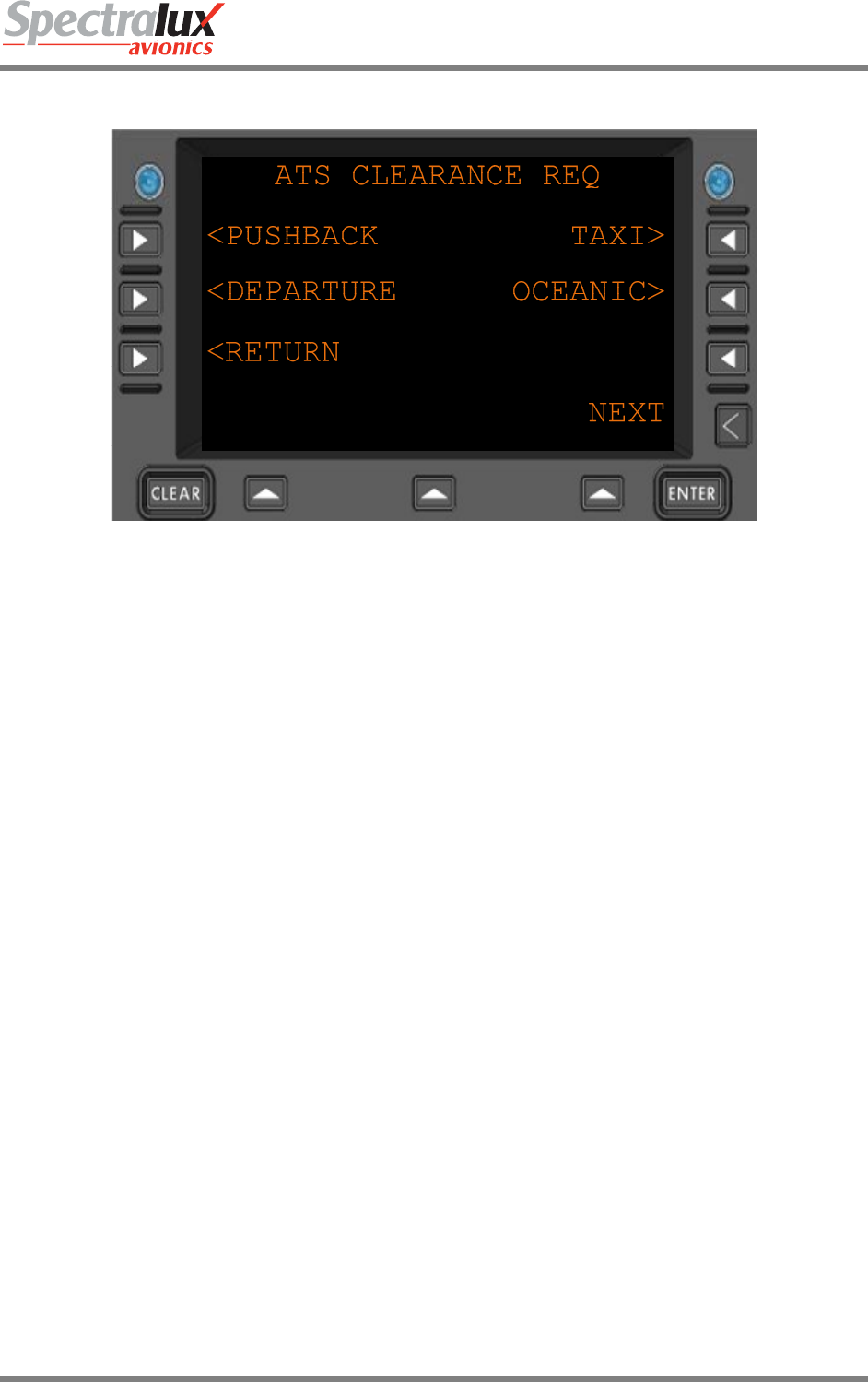
Dlink+CPDLC Users Guide
Document Number: UG-14114 Rev. - Page 93 of 201
4.3.2 ATS Request – Clearance Request Menu
Figure 4.3.2-1 Clearance Request Menu
<PUSHBACK Navigate to the Pushback Request Menu
<DEPARTURE Navigate to the Departure Request Menu
TAXI> Navigate to the Taxi Request Menu
OCEANIC> Navigate to the Oceanic Clearance Request Menu
<RETURN Return to previous page
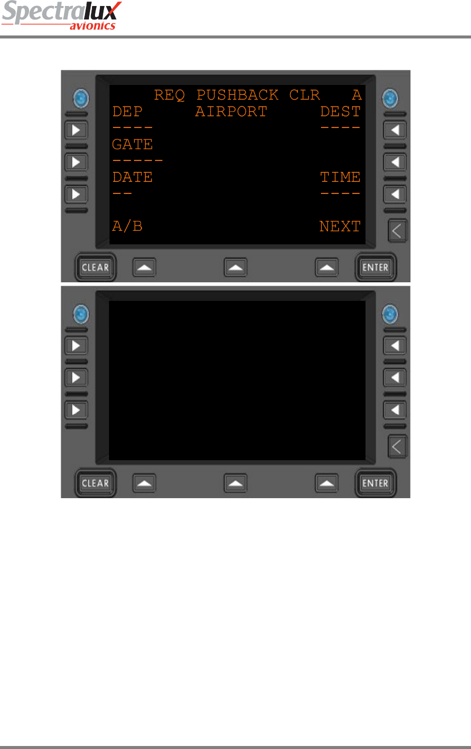
Dlink+CPDLC Users Guide
Document Number: UG-14114 Rev. - Page 94 of 201
4.3.2.1 Clearance Request – Request Pushback Clearance Menu
REQ PUSHBACK CLR B
FREE TEXT
------------------------
<RETURN SEND*
A/B NEXT
Figure 4.3.2-2 Request Pushback Clearance Request Menu
DEP The origin airport (AAAA)
GATE Departure gate (AAAAA)
DATE Date, day, of departure (ZZ)
DEST The Destination airport (AAAA)
TIME Time of departure (HHMM)
FREE TEXT Up to 24 characters of free text
SEND* If the Pilot-entered and system data is formatted correctly the SEND prompt
appears. Pressing SEND will transmit the formatted message
<RETURN Return to previous page
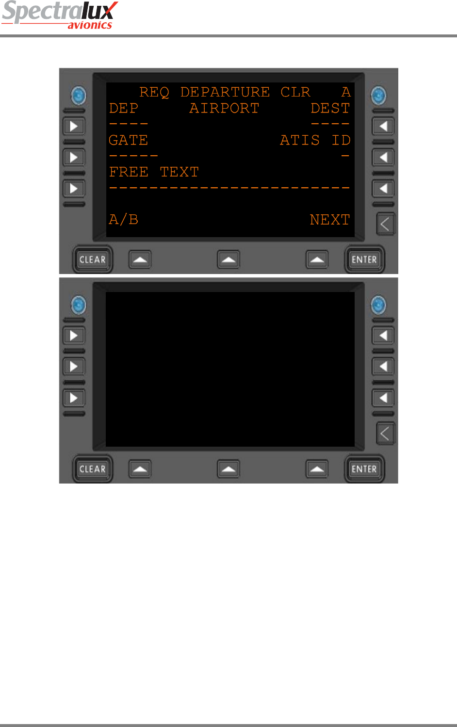
Dlink+CPDLC Users Guide
Document Number: UG-14114 Rev. - Page 95 of 201
4.3.2.2 Clearance Request – Request Departure Clearance Menu
REQ DEPARTURE CLR B
<RETURN SEND*
A/B NEXT
Figure 4.3.2-3 Request for Departure Clearance Menu
DEP The origin airport (AAAA)
GATE Departure gate (AAAAA)
DEST The Destination airport (AAAA)
ATIS ID The ATIS ID (A)
FREE TEXT Up to 24 characters of free text
SEND* If the Pilot-entered and system data is formatted correctly the SEND prompt
appears. Pressing SEND will transmit the formatted message
<RETURN Return to previous page
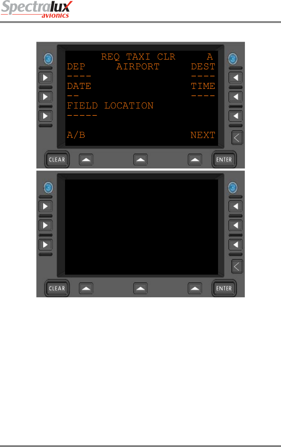
Dlink+CPDLC Users Guide
Document Number: UG-14114 Rev. - Page 96 of 201
4.3.2.3 Clearance Request – Request Taxi Clearance Menu
REQ TAXI CLR B
FREE TEXT
------------------------
<RETURN SEND*
A/B NEXT
Figure 4.3.2-4 Request For Taxi Clearance Menu
DEP The origin airport (AAAA)
DATE Date, day, of departure (ZZ)
DEST The Destination airport (AAAA)
TIME Departure time (HHMM)
FIELD LOCATION Location (AAAAA)
FREE TEXT Up to 24 characters of free text
SEND* If the Pilot-entered and system data is formatted correctly the SEND prompt
appears. Pressing SEND will transmit the formatted message.
<RETURN Return to previous page
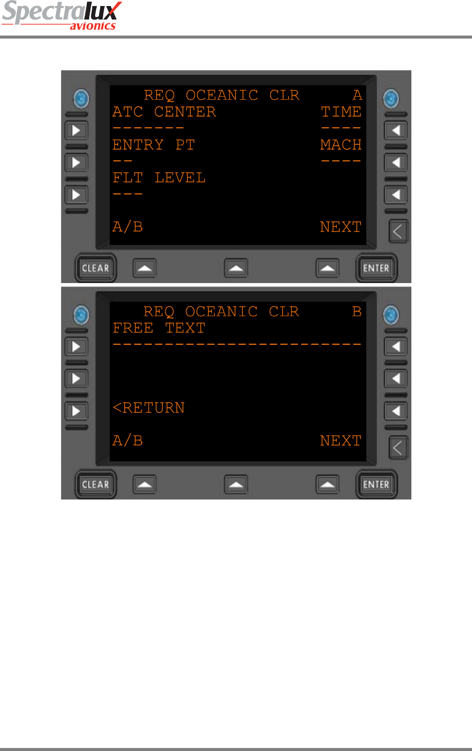
Dlink+CPDLC Users Guide
Document Number: UG-14114 Rev. - Page 97 of 201
4.3.2.4 Clearance Request – Request Oceanic Clearance Menu
Figure 4.3.2-5 Request For Oceanic Clearance Menu
ATC CENTER Identification of the ATC center. (AAAA) or (AAAAAAA)
ENTRY PT Station or way point of entry (AAAAA)
FLT LEVEL Altitude in thousands of feet (ZZZ)
TIME Entry time (HHMM)
MACH Mach speed (ZZZ)
FREE TEXT Up to 24 characters of free text
SEND* If the Pilot-entered and system data is formatted correctly the SEND prompt
appears. Pressing SEND will transmit the formatted message.
<RETURN Return to previous page
Dlink+CPDLC Users Guide
Document Number: UG-14114 Rev. - Page 98 of 201
4.3.3 ATS Request – Terminal Weather Information for Pilots Request Menu
TWIP REQUEST
TWIP CODE AIRPORT
[N] ----
<RETURN SEND*
NEXT
Figure 4.3.3-1 TWIP Request
TWIP CODE Terminal Weather Information for Pilots.
Selections:
“N" is Single TWIP Report
"C" is TWIP with Automatic update
"T" is Terminate automatic update of TWIP
AIRPORT Airport Identifier (AAAA)
SEND* If the Pilot-entered and system data is formatted correctly the SEND prompt
appears. Pressing SEND will transmit the formatted message.
<RETURN Return to previous page
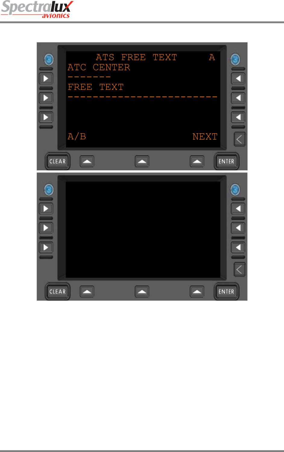
Dlink+CPDLC Users Guide
Document Number: UG-14114 Rev. - Page 99 of 201
4.3.4 ATS Request – ATS Free Text Message Menu
ATS FREE TEXT B
<RETURN SEND*
A/B NEXT
Figure 4.3.4-1 ATS Free Text Menu
ATC CENTER Identification of the ATC center. (AAAA) or (AAAAAAA)
FREE TEXT Up to 24 characters of free text
SEND* If the Pilot-entered and system data is formatted correctly the SEND prompt
appears. Pressing SEND will transmit the formatted message.
<RETURN Return to previous page
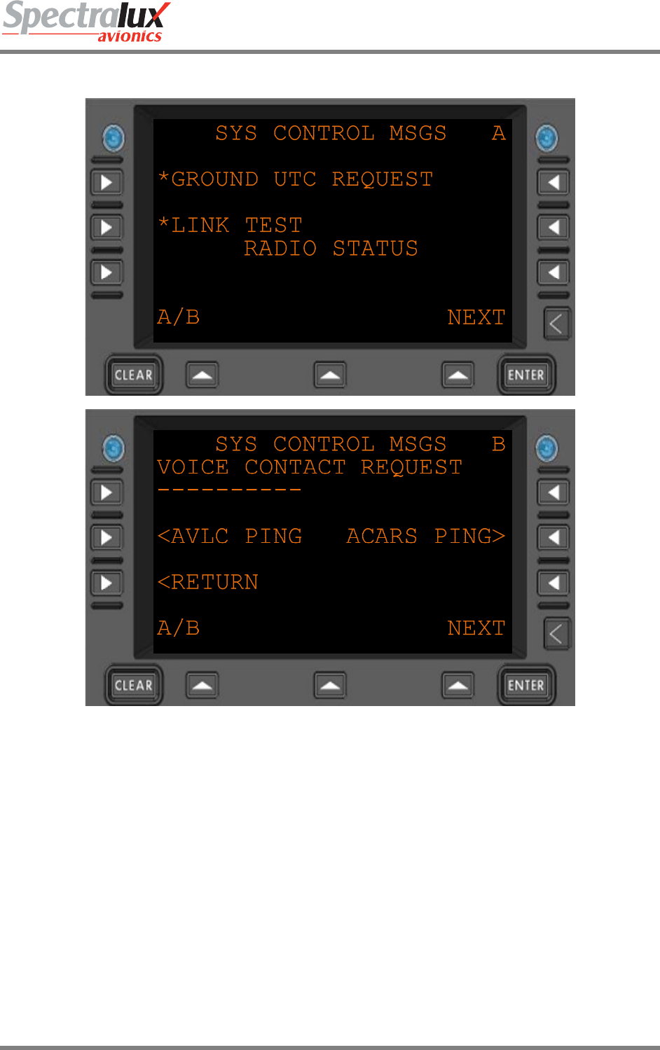
Dlink+CPDLC Users Guide
Document Number: UG-14114 Rev. - Page 100 of 201
4.4 System Control Messages Menu
Figure 4.3.4-1 System Control Messages Menu
*GROUND UTC
REQUEST
Send request for current UTC. Note Flight Number must be entered prior to
message being sent.
*LINK TEST Send link test message. Note Flight Number must be entered prior to message
being sent.
RADIO STATUS Shows current radio status
VOICE CONTACT
REQUEST
Free text (AAAAAAAAAA)
<AVLC PING Navigate to the AVLC Ping menu
ACARS PING> Navigate to the ACARS Ping Menu
<RETURN Return to previous page
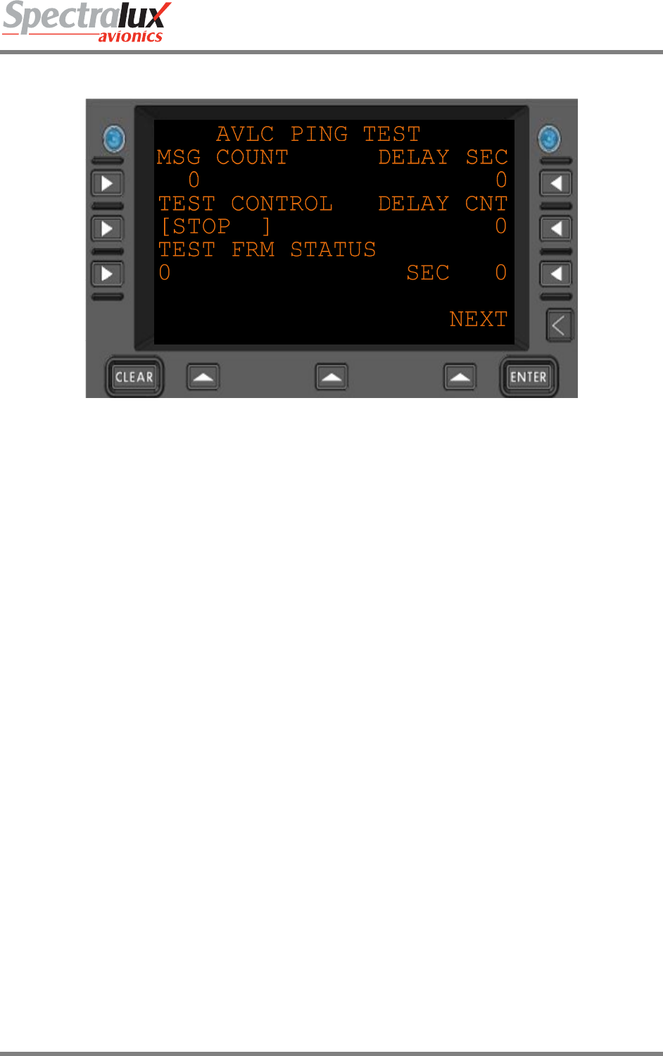
Dlink+CPDLC Users Guide
Document Number: UG-14114 Rev. - Page 101 of 201
4.4.1 System Control Messages – AVLC Ping Test Menu
Figure 4.4.1-1 AVLC Ping Test Menu
MSG COUNT How many test frames are to be sent.
DELAY SEC How many seconds to wait between test frame transmissions.
TEST CONTROL Instructions to the test function.
Select from:
STOP, GO, WAIT, FAIL, HOLD
DELAY CNT Seconds to wait until the next transmission.
TEST FRM STATUS Current testing status.
0 – Inactive
1 – Send message
2 – No Peer
3 – Not supported by peer
4 - Sending
5 – Contact Made.
SEC Average response time in seconds.
<RETURN Return to previous page
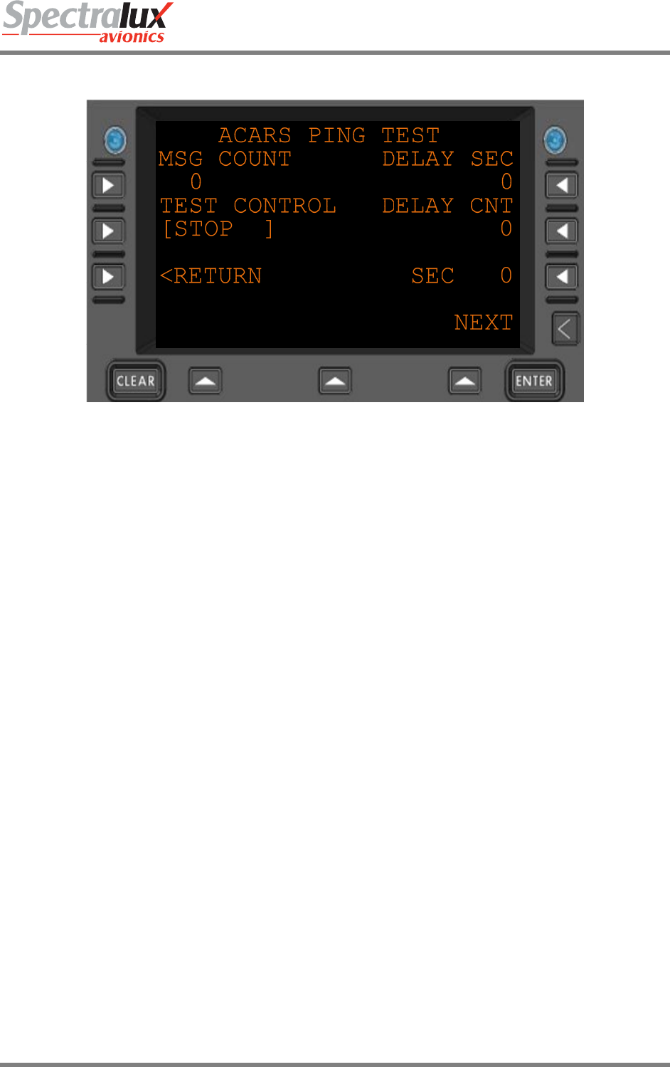
Dlink+CPDLC Users Guide
Document Number: UG-14114 Rev. - Page 102 of 201
4.4.2 System Control Messages – ACARS Ping Test Menu
Figure 4.4.2-1 ACARS Ping Test Menu
MSG COUNT How many test frames are to be sent.
DELAY SEC How many seconds to wait between test frame transmissions.
TEST CONTROL Instructions to the test function.
Select from:
STOP, GO, WAIT, FAIL, HOLD
DELAY CNT Seconds to wait until the next transmission.
SEC Average response time in seconds.
<RETURN Return to previous page