Spectralux 14114 Dlink+ w/CPDLC. All-in-one data communications, CPDLC and ACARS in a single LRU User Manual 2
Spectralux Corporation Dlink+ w/CPDLC. All-in-one data communications, CPDLC and ACARS in a single LRU Users Manual 2
Contents
- 1. Installation Manual
- 2. Users Manual 1
- 3. Users Manual 2
- 4. Users Manual
Users Manual 2

Dlink+CPDLC Users Guide
Document Number: UG-14114 Rev. - Page 103 of 201
5 ACARS Messages
The following lists show the various message types, by message label, which are supported while the
Dlink+ w/CPDLC is operating in the ACARS mode.
5.1 ARINC 618 Formatted Messages
Label Description
00 Emergency Situation Report
10-39 User Defined Messages
52 Ground UTC Request
54 Voice Contact Request
57 Alternate Aircrew Initiated Position Report
5R Aircrew Initiated Position Report
5U Weather Request
5Y Aircrew Revision to Previous ETA/Diversion Report
7A Aircrew Initiated Engine Data/Takeoff Thrust Report
7B Aircrew Entered Miscellaneous Message
Q0 Link Test
Q1 Departure/Arrival Report
Q2 Estimated Time of Arrival Report
QA OUT/Fuel Report (IATA Airport Code)
QB OFF Report (IATA Airport Code)
QC ON Report (IATA Airport Code)
QD IN/Fuel Report (IATA Airport Code)
QE OUT/Fuel/Destination Report (IATA Airport Code)
QF OFF/Destination Report (IATA Airport Code)
QG OUT/Return IN Report (IATA Airport Code)
QH OUT Report (IATA Airport Code)
QK Landing Report (IATA Airport Code)
QL Arrival Report (IATA Airport Code)
QM Arrival Information Report (IATA Airport Code)
QN Diversion Report (IATA Airport Code)
QP OUT Report (ICAO Airport Code)
QQ OFF Report (ICAO Airport Code)
QR ON Report (ICAO Airport Code)
QS IN Report (ICAO Airport Code)
QT OUT/Return IN Report (ICAO Airport Code)

Dlink+CPDLC Users Guide
Document Number: UG-14114 Rev. - Page 104 of 201
5.2 ARINC 622 Formatted Messages
Label Description
B1 Request Oceanic Clearance
B2 Oceanic Clearance Readback
B3 Request Departure Clearance
B4 Departure Clearance Readback Downlink
B7 Free Text to ATC
B9 Request ATIS Report
BB Terminal Weather Information for Pilots
BC Pushback Clearance Request
BD Expected Taxi Clearance Request

Dlink+CPDLC Users Guide
Document Number: UG-14114 Rev. - Page 105 of 201
6 ACARS Operation
The Aircraft Communication Addressing and Reporting System is a digital Datalink system for
transmission of short, relatively simple messages between aircraft and ground stations via radio or
satellite.
ACARS operation is an option on the Dlink+ w/CPDLC. If the option has not been enabled the menus
and functions, detailed in this document, will not be available to the user.
6.1 Start up
To begin using the ACARS system, assuming the system has been configured with the proper service
providers, frequency lists, and aircraft identification, it is necessary to enter in some basic information
about the flight.
Refer to the Main – Flight Information Menu section for a visual representation of the menus and an
explanation of the data contained within.
6.1.1 Entering the Flight Number
The flight number is a required data item used as an aid in identifying your aircraft to the various
operation and maintenance centers.
The flight number will consist of 1-4 numeric characters.
The flight number may be entered manually or may be collected from available aircraft information
broadcasted over the ARINC 429 busses and populated automatically.
6.1.2 Entering Origin and Destination Stations
The origin and destination stations consist of 4 alpha characters. The origin and destinations may be
entered manually or may be collected from available aircraft information broadcasted over the ARINC 429
busses and populated automatically.
6.2 Sending a Message
Pressing the ACARS function key will bring you directly to the ACARS Index Menu. (see: Figure
3.12.13-1 ACARS Index Menu). From the menu index follow the prompts to the desired message type.
Refer to ACARS Menus for specific details.
6.2.1 Requirements for Sending a Message
In order to facilitate sending an ACARS messages there must exist a link to the ground through a service
provider. When there is no established link the Dlink+ w/CPDLC will report “NO COMM” in the advisory
area of the display. The COMM Status may be viewed by pressing the READ Function key. This will
display the Monitor Menu, showing the COMM Status and the states of various services (VHF, Satcom,
and ATN).
6.3 Reading Received Messages
When an ACARS message is received the ACARS annunciator will be lit. At this point pressing the MSG
function key will display the Message Log Menu (see ACARS Index – Message Log Menu). Navigate to
the particular message to be viewed and press the LSK indicated. Refer to (ACARS Index – Message
Log Viewing Menu).

Dlink+CPDLC Users Guide
Document Number: UG-14114 Rev. - Page 106 of 201
7 CPDLC Operation
7.1 CPDLC Menus
7.1.1 CPDLC – Index Menu
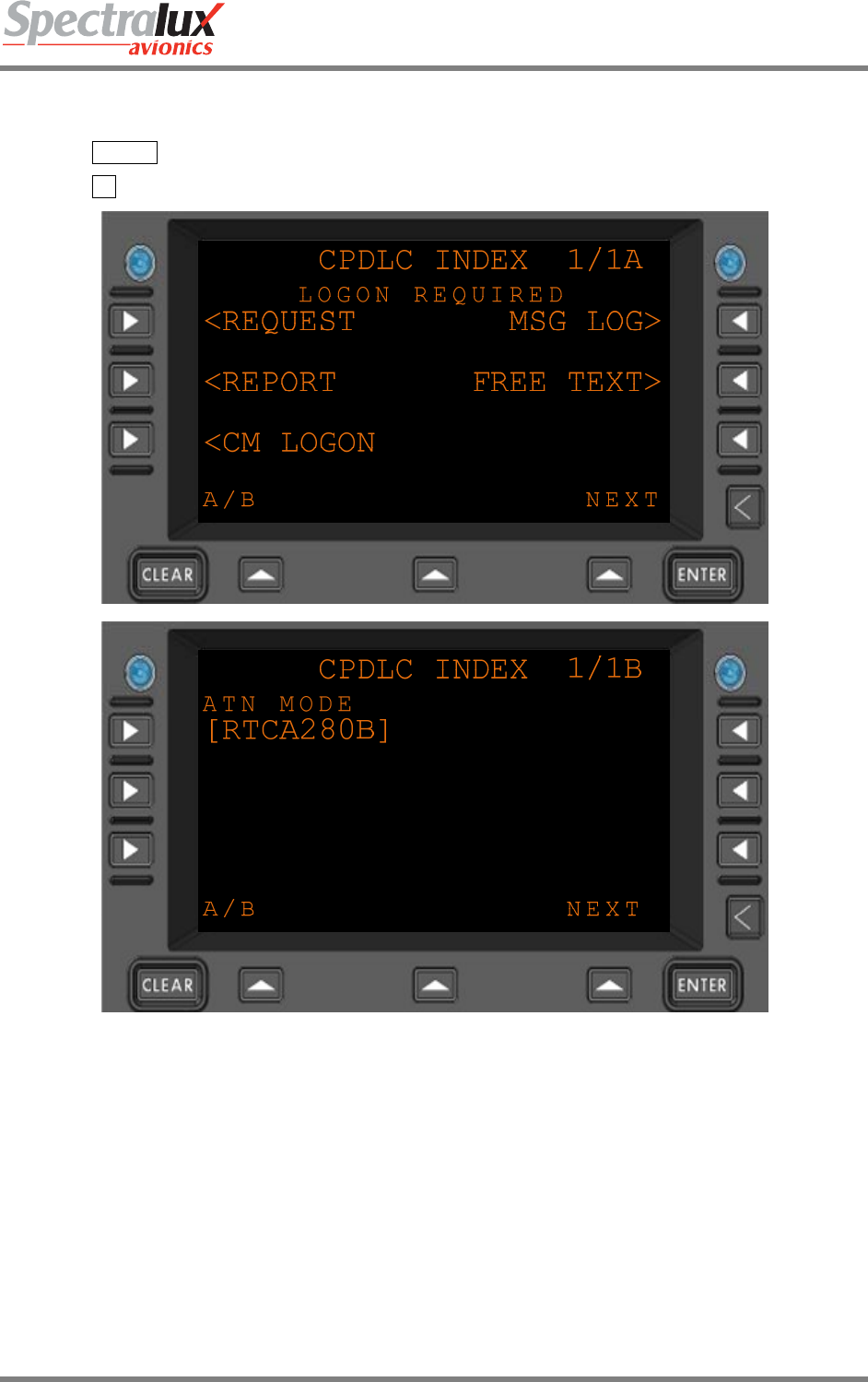
The CPDLC INDEX Menu is the primary interface for CPDLC Operation. From this menu, access is
provided to the CM Logon Menu (see Section7.1.3), the Request Menu (see Section 7.1.5), the Message
Log Menu (see Section 7.1.4), the Report Menu (see Section 7.1.13), and the Free Text Menu (see
Section 7.1.2). When configuring any of the possible messages on these menus all required fields must
be filled in to get a VERIFY Prompt, This VERIFY Prompt will only be displayed when all required fields
have been configured. The fields required will vary depending on the message being configured. This is
talked about more specifically in the sections that follow for each type of message that can be configured
through sub-menus of the CPDLC INDEX Menu.
In addition to providing basic access to other CPDLC Menus, the operator is provided with the option to
change the ATN Operational Mode. The ‘ATN Mode’ can be configured to RTCA DO280B or Link 2000.
When configured for RTCA DO280B operation, most of the RTCA DO280B defined message set is
available for use. When configured for Link2000 Operational mode, the available message set (both
uplink and downlink) is limited to those messages supported in the European Link 2000 environment (see
Sections 7.3.1 and 7.3.2).
The ATN Mode may be toggled between Link 2000 and RTCA DO280B by selecting the L1 Line Select
Key on the B-Page of the CPDLC INDEX Menu.
Dlink+CPDLC Users Guide
Document Number: UG-14114 Rev. - Page 107 of 201
PAGE NAVIGATION:
1. ► CPDLC Function Key
2. ► L1 Line Select Key from the User Menu (See section 3.2)
Figure 7.1.1-1 CPDLC Index Menu (Menus A and B)
Dlink+CPDLC Users Guide
Document Number: UG-14114 Rev. - Page 108 of 201
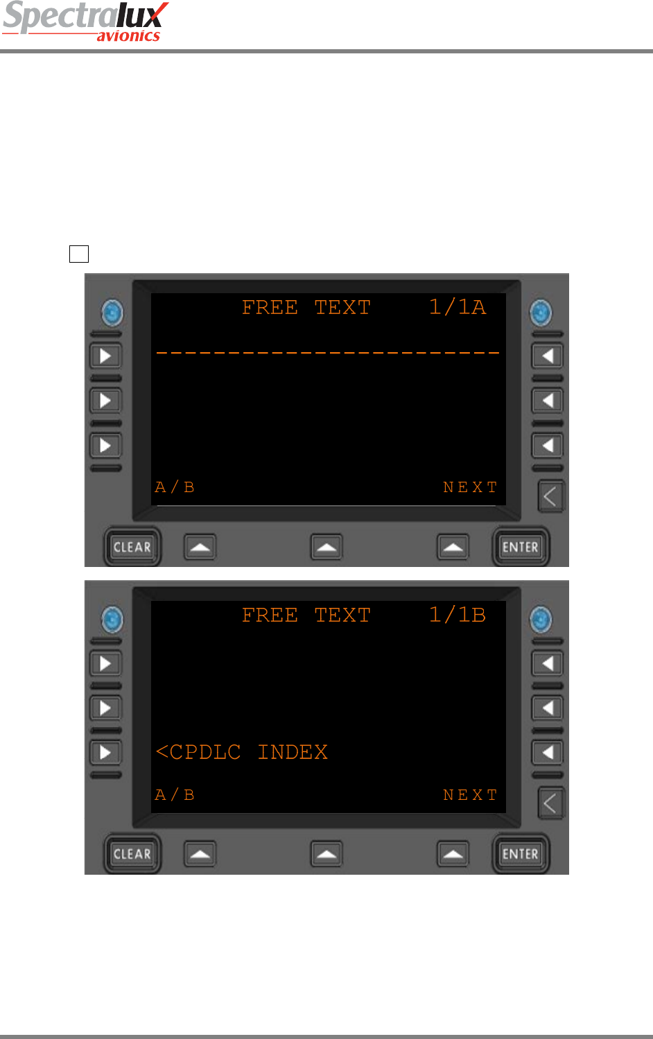
7.1.2 CPDLC – Free Text Menu
The FREE TEXT Menu allows entry of a free text message that may be down-linked to ATC. Up to 256
characters are permitted in the free text message. Entries are displayed on lines 1-5. When all 5 lines
have been used on the first page a second FREE TEXT page becomes available. If all of the space on
the second FREE TEXT page has been used, then a third FREE TEXT page becomes available. The
third FREE TEXT page will accept just one line of text, limited to 16 characters. These last 16 characters
result in a maximum of a 256 character Free Text message being available if each preceding line is
completely filled.
PAGE NAVIGATION:
A. ► R2 Line Select Key from the A-Page of the CPDLC INDEX Menu (See 7.1.1)
Figure 7.1.2-1 CPDLC Free Text Menu (Menus A and B)
FREE TEXT Format: Each line permits up to 24 characters of free text. Text is
entered in the scratch pad and up-selected to the line with
dashes in it. Any text line may be overwritten by up selecting the
contents of the scratch pad to it.

Dlink+CPDLC Users Guide
Document Number: UG-14114 Rev. - Page 109 of 201
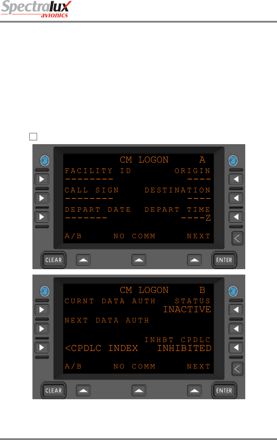
7.1.3 CPDLC – CM Logon Menu
The CM (Context Management) LOGON Menu provides an interface that may be used to initiate a CM
Logon to the End System of an Air Traffic Control (ATC) authority. This action results in the transfer of
information regarding various data link capabilities between the ground and the airborne systems and in
general makes the ATN Network aware of the aircrafts presence and its ability to support ATN.
A CM Logon is usually a prerequisite to establishing a CPDLC connection with ATC. Usually this would
be performed prior to departure. Under some circumstances, the CM connection can be initiated by the
ground using a Contact Request when ATC is already aware of an Aircrafts presence and capabilities,
but this is not the normal way in which CM is established. For instance, if a manual CM logon has been
performed at some point, the ATN Network will have been made aware of the aircraft network address
and its data link capabilities. At some future point in time, a second facility may issue a Contact Request
to the aircraft from the current facility directing Dlink+ w/CPDLC to contact it. When this happens, the CM
function will automatically send a CM-Logon Request to the new station. If a valid CM-Logon response is
received from that new station, a CM Logon will exist with the new facility. The only indication of this
happening will be the Facility ID changing on the CM Logon page to the Facility ID contained in the
Contact Request (see 7.1.3).
This menu may also be used to log off of CM. It also provides access to view the current status when
viewing page B of the CM Logon Menu. The status is set to INACTIVE when CM is not logged on and as
ACTIVE when CM is logged on.
The Logon Prompt appears in R2 of the B Menu when all prerequisites to perform a CM Logon have
been met. In order for the CM Logon Prompt to appear, the following conditions must be satisfied:
1. There must be an active connection to the ATN Network. This can be checked from the Monitor Menu
by pressing the USER Function Key then the R2 Line Select Key and then the L1 Line Select Key
(See section 3.4.1).
2. A valid ‘FACILITY ID’, ‘ORIGIN’, ‘CALL SIGN, and ‘DESTINATION must be entered into the CM
Logon Menu.
NOTE: Entry of data into Departure Time and Departure Date fields is optional in a sense. If the above
conditions are met, a CM Logon prompt will appear in R2 of the B Menu even if this information is
not present. However, if entry is made into one of these fields, then both the DEPART TIME and
DEPART DATE fields must be provided. A CM Logon prompt will not appear if entry is made into
one field and not the other.
Besides providing the CM Logon prompt in R2 and a means to return to the CPDLC Index Menu in L3,
the B Menu provides status information and the ability to Inhibit CPDLC.
The Current Data Authority is displayed in L1. This status defines the active ATC Center that has current
responsibility for CPDLC communication with the aircraft. All commands to the aircraft or requests from
the aircraft are processed by this data authority. No pilot action is required to obtain the Current Data
Authority as this is controlled by the ground.
The Next Data Authority is displayed in L2. This is the next ATC Center that will assume responsibility for
CPDLC communication with the aircraft after communication has ended with the Current Data Authority.
There may not always be a Next Data Authority, but when there is, its existence is controlled by the
ground. No pilot action is required in regard to the Next Data Authority with the possible exception of
action required when switching between data authorities which is directed by specific CPDLC messages
(see Section ?).
The STATUS displayed in R1. This is the CM connection status, not the CPDLC connection status. An
active CM connection is required for CPDLC use. Without a CM connection access is limited. If there is
an active CM connection the status will be set to ACTIVE. Otherwise the status will be INACTIVE.
CPDLC Communication may be inhibited by the Pilot. This option is made available and displayed in R3.
CPDLC is automatically inhibited until a CM connection has been established. After the CM status
changes to ACTIVE in R1, CPDLC can be inhibited by selecting R3.
When CPDLC is inhibited by selecting R3, the CM connection is aborted. If the operator later performs a
manual CM Logon, the assumption is made that this is done for the sole intention of establishing CPDLC
(since that is the only ATN application available to him at this time). As a result, the action to log onto CM
will automatically un-inhibits CPDLC.
Dlink+CPDLC Users Guide
Document Number: UG-14114 Rev. - Page 110 of 201
If the ground issues a contact request while CPDLC is inhibited, the CM application will honor the contact
request and log onto the respective ground station (if it is not a blind contact request, see below).
However, in this case, CPDLC will stay inhibited because the operator has not yet provided permission or
any indication that he is willing to allow a CPDLC session. If the ground later attempts to sends a CPDLC
start request, Dlink+ w/CPDLC will reject the start request and provide a message to ATC that the crew
has inhibited CPDLC. No pilot action is required for this.
In some cases, the ATN Network may have knowledge that an aircraft is in the network from a previous
CM Logon. If the ground sends a contact request following power up, and no CM Station was previously
logged onto, this is termed a blind contact, and it will not result in a automatic CM Logon. In this case, the
information for the end system which contacted the aircraft will be displayed on the CM Logon page and it
is up to the operator to press the Logon prompt in order to perform the CM Logon.
PAGE NAVIGATION:
A. ► L3 menu key from the CPDLC INDEX Menu (See section 7.1.1)
Figure 7.1.3-1 CM LOGON Menu (Menus A and B)

Dlink+CPDLC Users Guide
Document Number: UG-14114 Rev. - Page 111 of 201
FACILITY ID Format: 4-8 characters
Range: A-Z, 0-9
CALL SIGN Format: 2-8 characters
Range: A-Z, 0-9
DEPART DATE Format: DDMMMYY
DD = day of the month
MMM = first 3 characters of the month
YY = last 2 digits of the year
ORIGIN AND DESTINATION Format: 4 characters
Range: A-Z, 0-9
DEPART TIME
Format: HHMM
HH = hours
MM = minutes
Hours range: 00-23
Minutes range: 00-59
Dlink+CPDLC Users Guide
Document Number: UG-14114 Rev. - Page 112 of 201
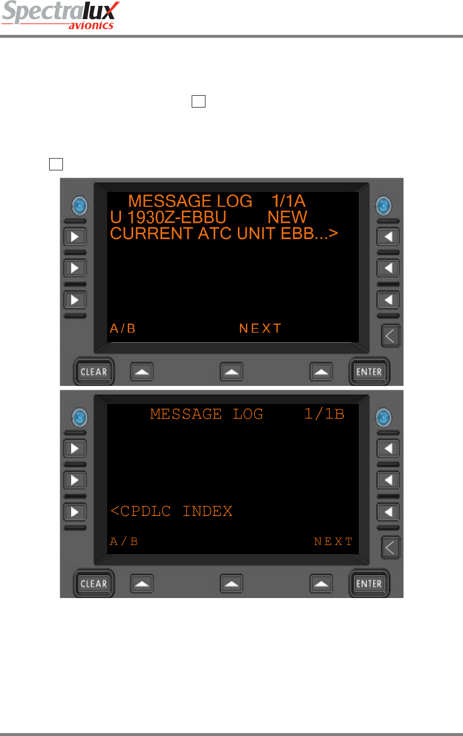
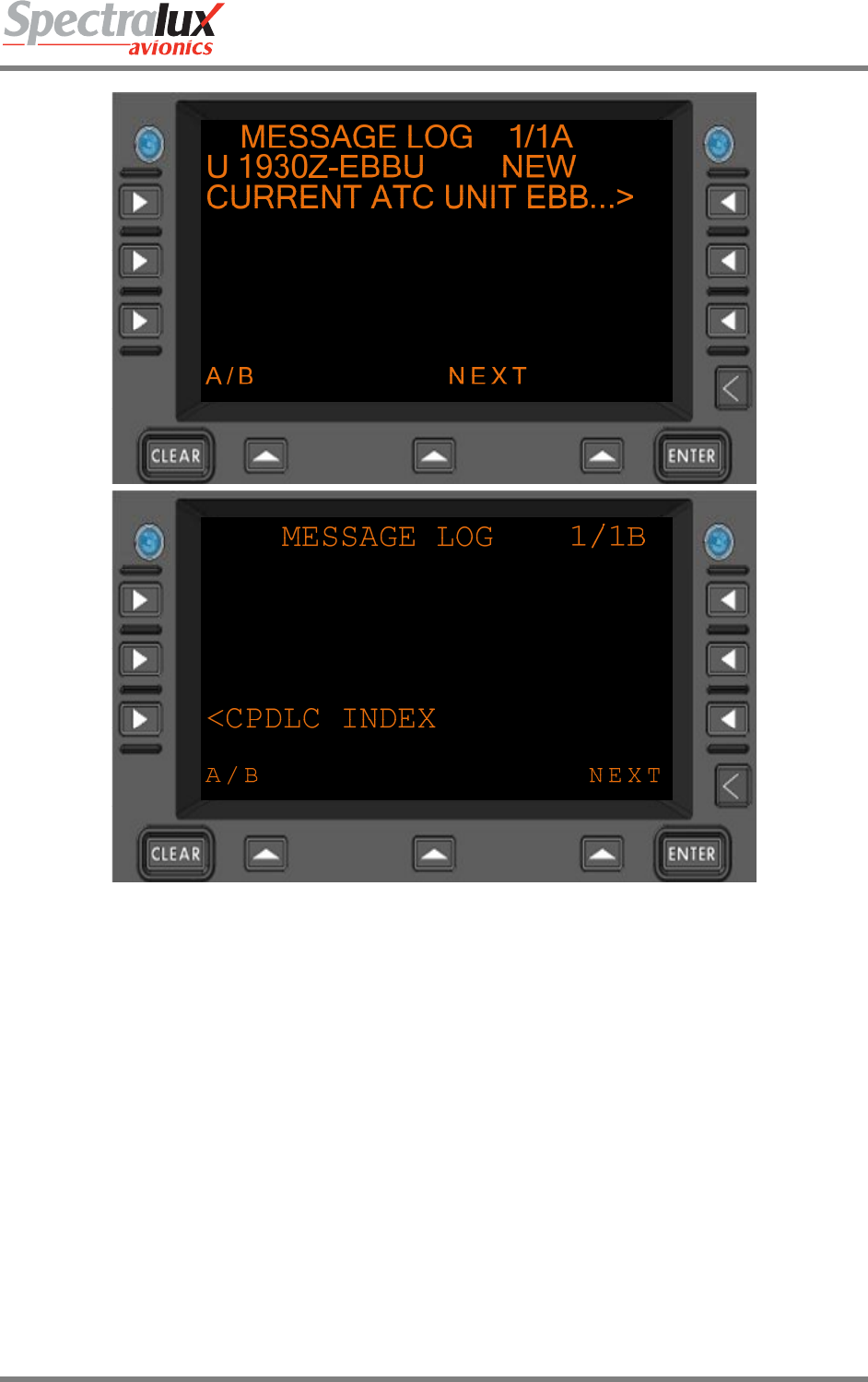
7.1.4 CPDLC – Message Log Menu
The MESSAGE LOG Menu provides access to all the CPDLC message elements sent and received over
the ATN network. The MESSAGE LOG will also provide the ability to review the content of all past
messages. To open a message in the message log, press the corresponding Line Select Key to the right
of the message. In the example below the R1 Line Select Key would be pressed to open the uplink that
is displayed in the message log.
PAGE NAVIGATION:
A. ► R1 Line Select Key from the CPDLC INDEX Menu (See section 7.1.1)
Figure 7.1.4-1 MESSAGE LOG Menu (Menus A and B)
To view the content of the complete message, the right-hand line select keys are used. Selection of a
right-hand line select key on which a truncated message is displayed provides access to the MESSAGE
REVIEW page, where the entire content of the message is displayed.
Dlink+CPDLC Users Guide
Document Number: UG-14114 Rev. - Page 113 of 201
Figure 7.1.4-2 MESSAGE LOG Menu (Menus A and B)
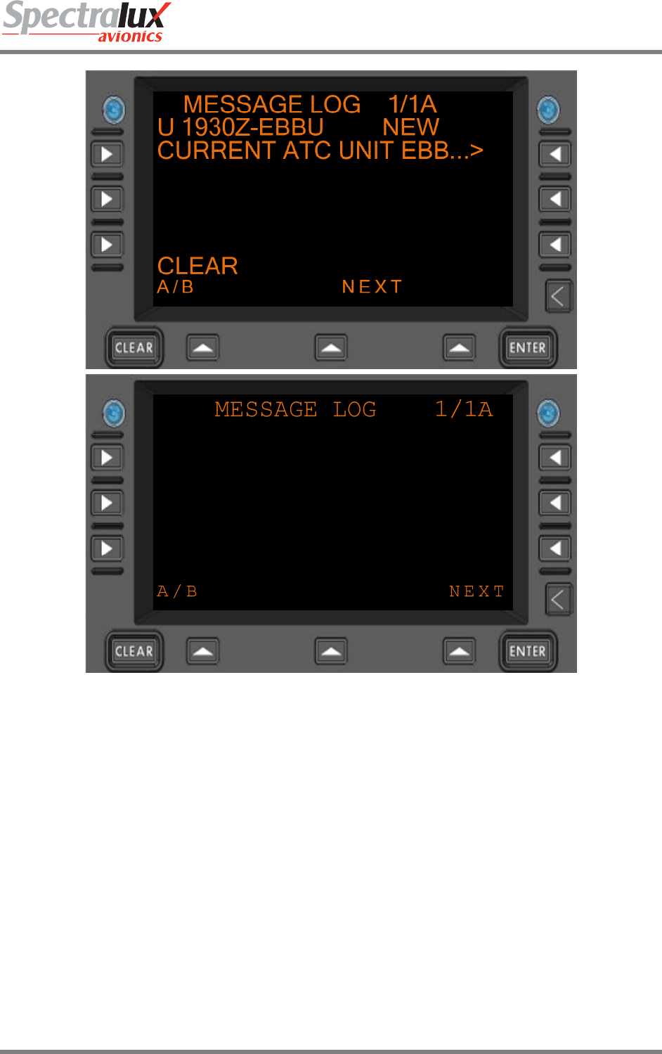
There are two ways that messages in the message log can be cleared. The first happens automatically
10 minutes after the flight is complete and the plane has landed. This clears all messages in the
message log. The second is done manually. To delete messages manually the left-hand line select keys
are used after pressing the clear function key to enter clear into the scratch pad. Selecting the left-hand
line select key that corresponds to a particular message when clear is in the scratch pad will clear the
message when the message status is not NEW, OPEN or SENDING. The message status must be
ACCEPTED, REJECTED, CLOSED or ABORTED in order to clear a message. This ensures that a
message has been reviewed and responded to (if needed) prior to its removal from the log.
Dlink+CPDLC Users Guide
Document Number: UG-14114 Rev. - Page 114 of 201
Figure 7.1.4-3 Clearing a Message from the CPDLC Message Log
Dlink+CPDLC Users Guide
Document Number: UG-14114 Rev. - Page 115 of 201
7.1.5 CPDLC – Request Index Menu
The REQUEST INDEX Menu is the primary interface that is used to make requests of ATC. The content
and operational features of this menu change depending on the ATN Operational Mode, as discussed in
this Section. For information on ATN Operational Modes, see Sections 7.1.1 and 7.3.
PAGE NAVIGATION:
A. ► L1 menu key from the CPDLC INDEX menu (See section 7.1.1)
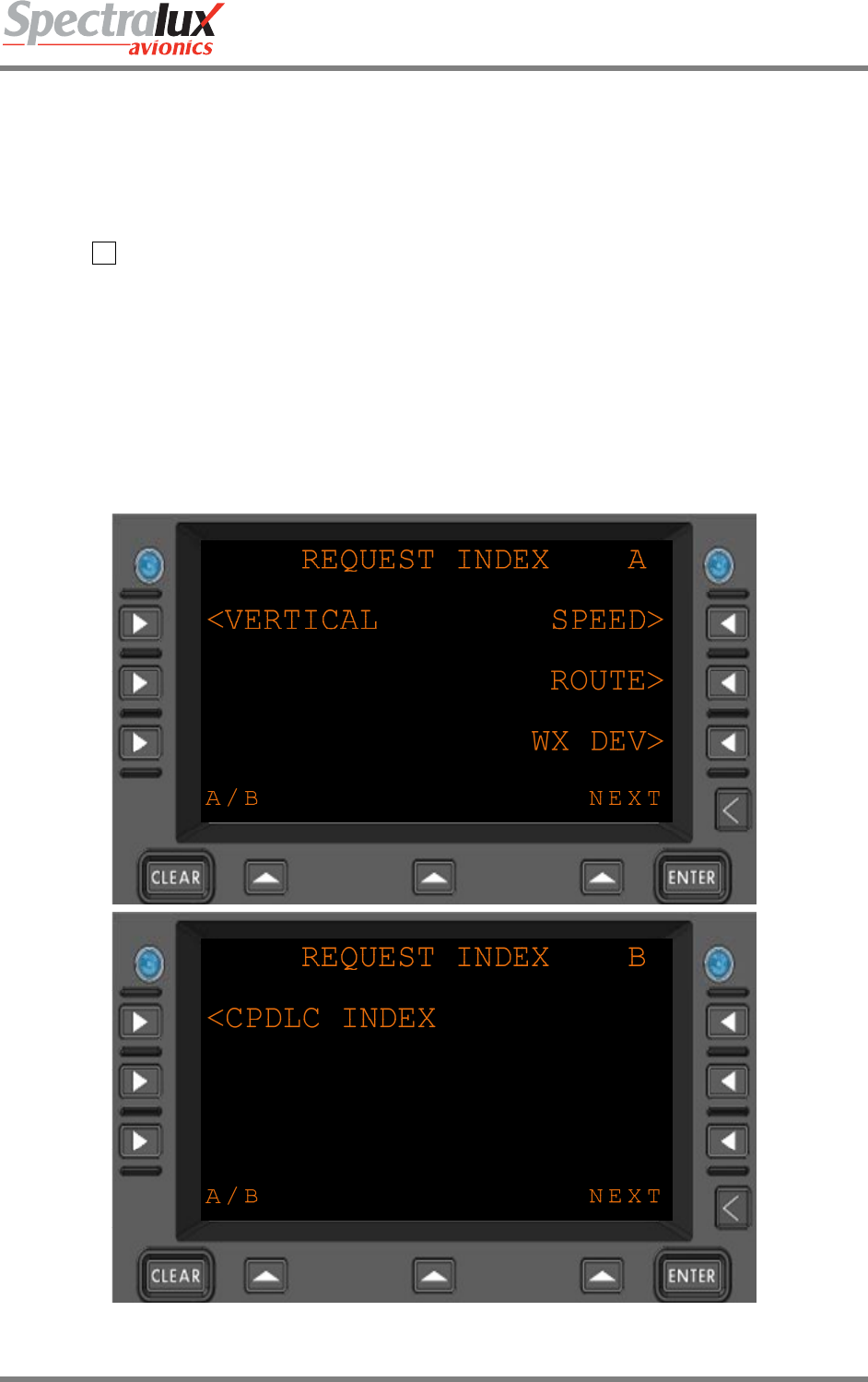
7.1.5.1 REQUEST INDEX Menu, Link 2000 Operational Mode
When configured for Link2000, the REQUEST INDEX Menu supports the following requests:
• Vertical Request
• Speed Request
• Route Mod Request (Route Modification Request)
• WX DEV Request (Weather Deviation Request)
Figure 7.1.5-1 REQUEST INDEX Menu (Menus A and B), LINK 2000
Dlink+CPDLC Users Guide
Document Number: UG-14114 Rev. - Page 116 of 201
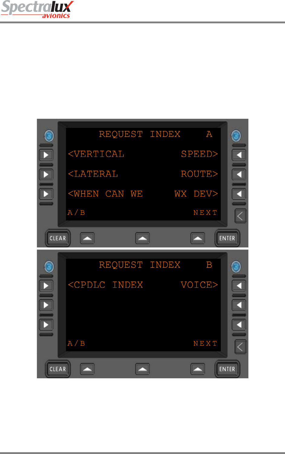
7.1.5.2 REQUEST INDEX Menu, RTCA DO 280 B Operational Mode
The REQUEST INDEX Menu provides the ability to access the Vertical Request Menu (see section7.1.6),
the Lateral Request Menu (see section 7.1.10), The Route Request Menu (see section 7.1.8), the
Request Weather Deviation Menu (see section7.1.9), the When Can We Menu (see section 7.1.11), and
Speed Request Menu (see section7.1.7). Each of these requests can be selected using the
corresponding Line Select Keys.
Figure 7.1.5-2 depicts the Request Index Menu as it appears when operating in RTCA DO280B mode.
Figure 7.1.5-2 Request Index (Menu A and B), DO 280B
Dlink+CPDLC Users Guide
Document Number: UG-14114 Rev. - Page 117 of 201
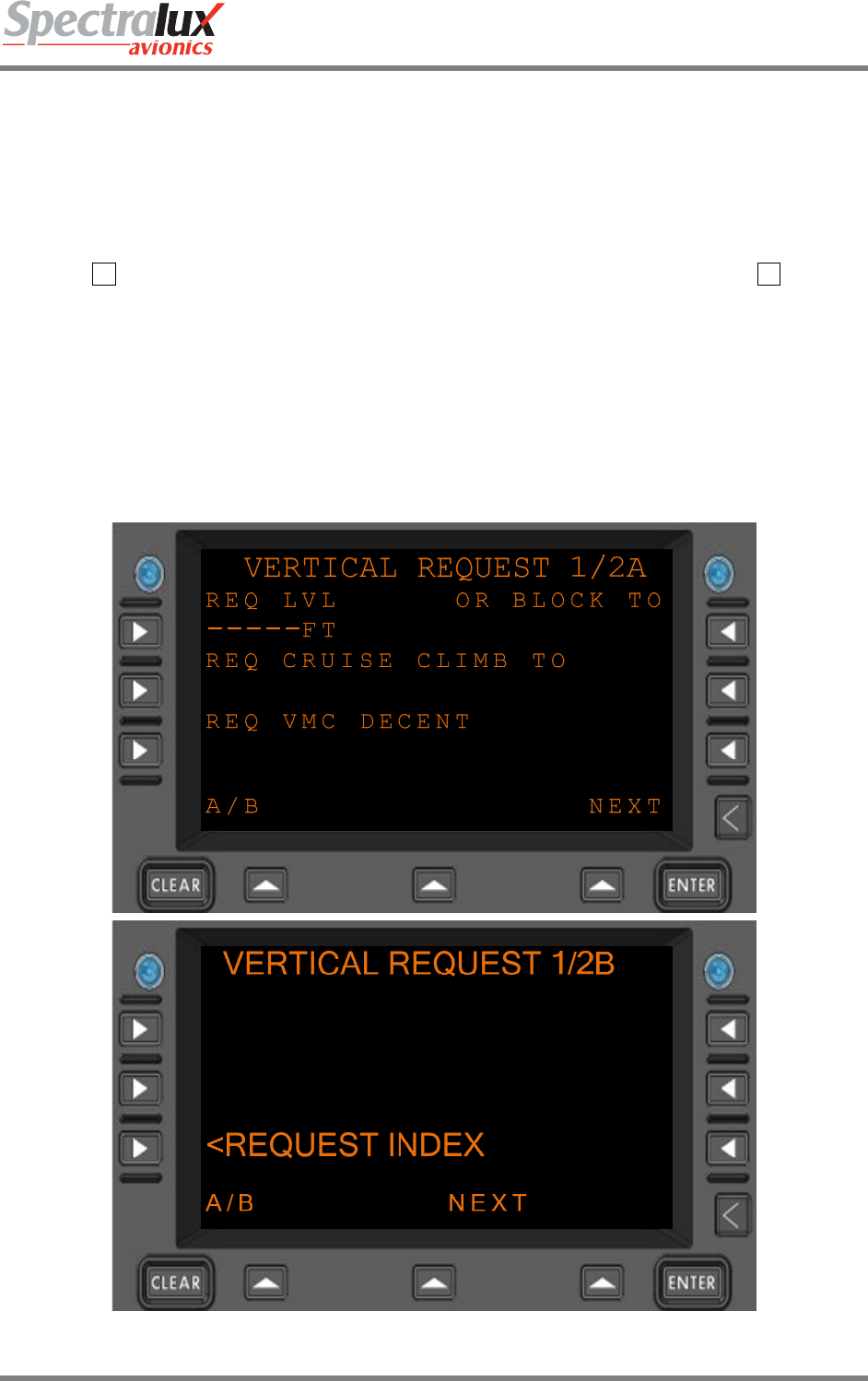
7.1.6 CPDLC – Vertical Request Menu
The VERTICAL REQUEST Menu provides a means by which the operator may request changes to the
current vertical location of the aircraft. The content and operational features of this menu change
depending on the ATN Operational Mode, as discussed in this Section. For information on ATN
Operational Modes, see Sections 7.1.1 and 7.3.
PAGE NAVIGATION:
A. ► L1 Line Select Key from the CPDLC INDEX Menu (See section 7.1.1) then ► L1 Line
Select Key from the REQUEST INDEX Menu (See section 7.1.5)
7.1.6.1 VERTICAL RQUEST Menu, Link 2000 Operational Mode
When configured for LINK 2000 Mode the following Vertical Requests are valid:
• Request Level (REQ LVL must contain a valid level)
• Request Climb To Level (REQ CLB TO must contain a valid level)
• Request Descent To Level (REQ DES TO must contain a valid level)
Figure 7.1.6-1 VERTICAL REQUEST Menu Page 1 (Menus A and B), LINK 2000
Dlink+CPDLC Users Guide
Document Number: UG-14114 Rev. - Page 118 of 201
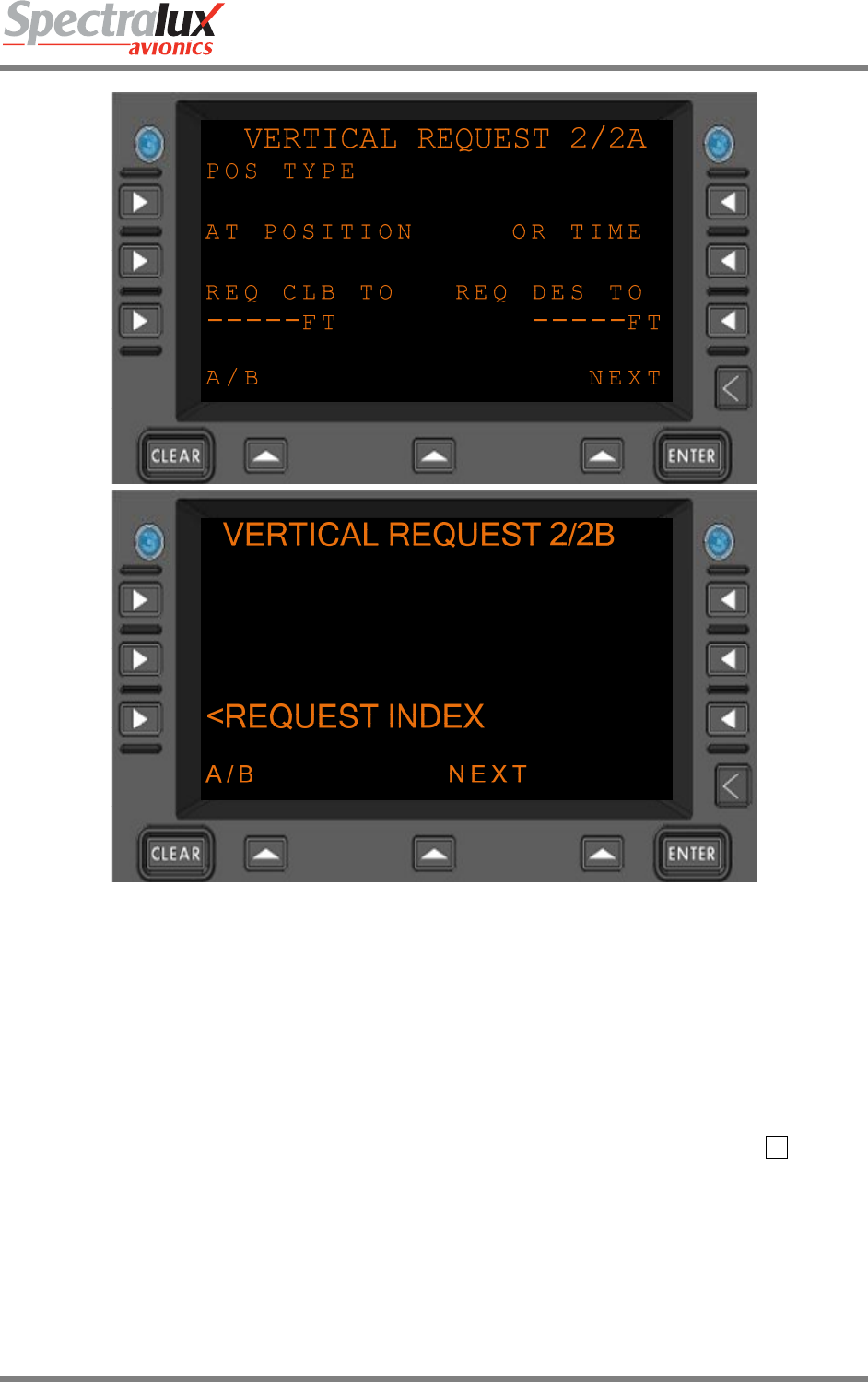
Figure 7.1.6-2 VERTICAL REQUEST Menu Page 2 (Menus A and B), LINK 2000
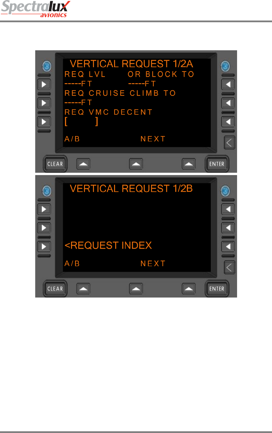
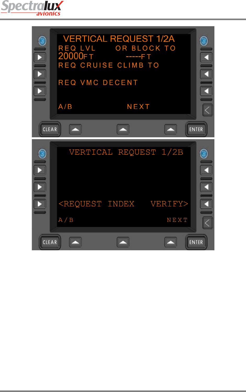
7.1.6.2 RTCA DO 280 B Operational Mode
When configured for RTCA DO 280B Mode the following Vertical Requests are valid:
• Request Level (REQ LVL must contain a valid level)
• Request Block Level (REQ LVL and OR BLOCK TO must contain valid levels)
• Request Cruise Climb To Level (REQ CRUISE CLIMB TO must contain a valid level)
• Request VMC Descent (REQ VMC DESCENT field must be selected by pressing the L1 line
select key)
• Request Climb To Level (REQ CLB TO must contain a valid level)
• Request Descent To Level (REQ DES TO must contain a valid level)
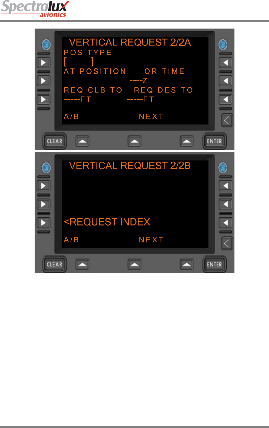
• At Position Request Climb To Level (POS TYPE, AT POSITION, and REQ CLB TO fields must
contain valid values)
• At Position Request Descent To Level (POS TYPE, AT POSITION, and REQ DES TO fields must
contain valid values)
Dlink+CPDLC Users Guide
Document Number: UG-14114 Rev. - Page 119 of 201
• At Time Request Climb To Level (OR TIME and REQ CLB TO fields must contain valid values)
• At Time Request Descent to Level (OR TIME and REQ DES TO fields must contain valid values)
Figure 7.1.6-3 VERTICAL REQUEST Menu Page 1 (Menus A and B), DO 280B
Dlink+CPDLC Users Guide
Document Number: UG-14114 Rev. - Page 120 of 201
Figure 7.1.6-4 VERTICAL REQUEST Menu Page 2 (Menus A and B), DO 280B
REQ LVL
REQ CRUISE CLIMB TO
REQ CLB TO
REQ DES TO
BLOCK TO FIELDS
Format: NNNNN where “N” is a numerical entry in the range of -600-70000.
TIME Format: : HHMM
HH = hours
MM = minutes
Hours range: 00-23
Minutes range: 00-59

Dlink+CPDLC Users Guide
Document Number: UG-14114 Rev. - Page 121 of 201
AT POSITION Format:
1. When associated Position Type field is set to NAVAID (Navaid), the
following entry is valid:
a) Format: AAAA
b) Where: “A” is an alpha-numeric entry representing a
waypoint,
navaids or airport identifier
c) Range: 0-9, A-Z (1- 4 Characters)
2. When associated Position Type field is set to FIX (FixName), the
following entries are valid:
a) Format: AAAAA
b) Where: “A” is an alpha-numeric entry representing a
waypoint,
navaids or airport identifier.
c) Range: 0-9, A-Z (1-5 Characters)
3. When associated Position Type field is set to AIRPORT (airport), the
following entry is valid:
a) Format: AAAA
b) Where: “A” is an alpha-numeric entry representing a
waypoint,
navaids or airport identifier
c) Range: 0-9, A-Z (4 characters)
4. When associated Position Type field is set to LAT/LON
(latitudeLongitude), the following entries are valid:
a) Format: ADDMMSS/BDDDMMSS
b) Where: “A” is either N or S
“B” is either E or W
“DD” is a numerical entry representing geographical
latitude
“DDD” is a numerical entry representing
geographical longitude
“MM” is a numerical entry representing
geographical minutes.
“SS” is a numerical entry representing geographical
seconds.
c) Range: “DD” is 00-89
“DDD” is 000-179
“MM” is 0-59
“SS” is 0-59
For an example of the vertical request page with the ‘REQ LVL’ Line Field filled in and the ‘VERIFY’
prompt shown on Vertical Request menu 1B-Page see Figure 7.1.6-5.
Dlink+CPDLC Users Guide
Document Number: UG-14114 Rev. - Page 122 of 201
Figure 7.1.6-5 VERTICAL REQUEST Menu, Verify Prompt Displayed
Dlink+CPDLC Users Guide
Document Number: UG-14114 Rev. - Page 123 of 201
7.1.7 CPDLC – Speed Request Menu
The SPEED REQUEST Menu provides a means by which the operator may request a change of speed.
The content of this menu changes depending on the ATN Operational Mode Selected. This Section
discusses this menu for both RTCA DO 280 and LINK 2000 Operational Modes. For information on ATN
Operational Modes, see Sections 7.1.1 and 7.3.
PAGE NAVIGATION:
A. ► L1 Line Select Key from the CPDLC INDEX menu (See section 7.1.1) then ► R1 Line
Select Key from the REQUEST INDEX menu (See section 7.1.5)
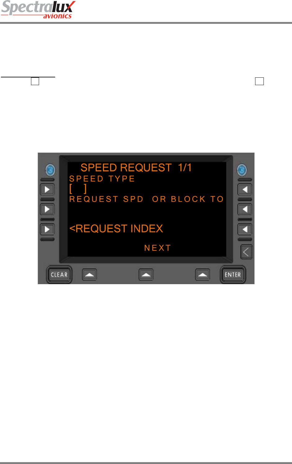
7.1.7.1 SPEED REQUEST Menu, Link 2000 Operational Mode
When configured for LINK 2000 Mode the following Speed Request is valid:
• Request Speed (SPEED TYPE and REQUEST SPD fields must contain valid values)
Figure 7.1.7-1 SPEED REQUEST Menu, LINK 2000
7.1.7.2 SPEED REQUEST Menu, RTCA DO 280 B Operational Mode
When configured for RTCA DO 280B Mode the following Speed Requests are valid:
• Request Speed (SPEED TYPE and REQUEST SPD fields must contain valid values)
• Request Speed Range (SPEED TYPE, REQUEST SPD, and OR BLOCK TO fields must contain
valid values)
Dlink+CPDLC Users Guide
Document Number: UG-14114 Rev. - Page 124 of 201
Figure 7.1.7-2 SPEED REQUEST Menu, DO 280B
REQUEST SPD English Format: NNN where “N” is a numerical
entry in the range of 0-400.
Metric Format: NNN where “N” is a numerical
entry in the range of 0-800.
BLOCK TO
Format: NNNNN where “N” is a numerical entry in
the range of -600-70000.
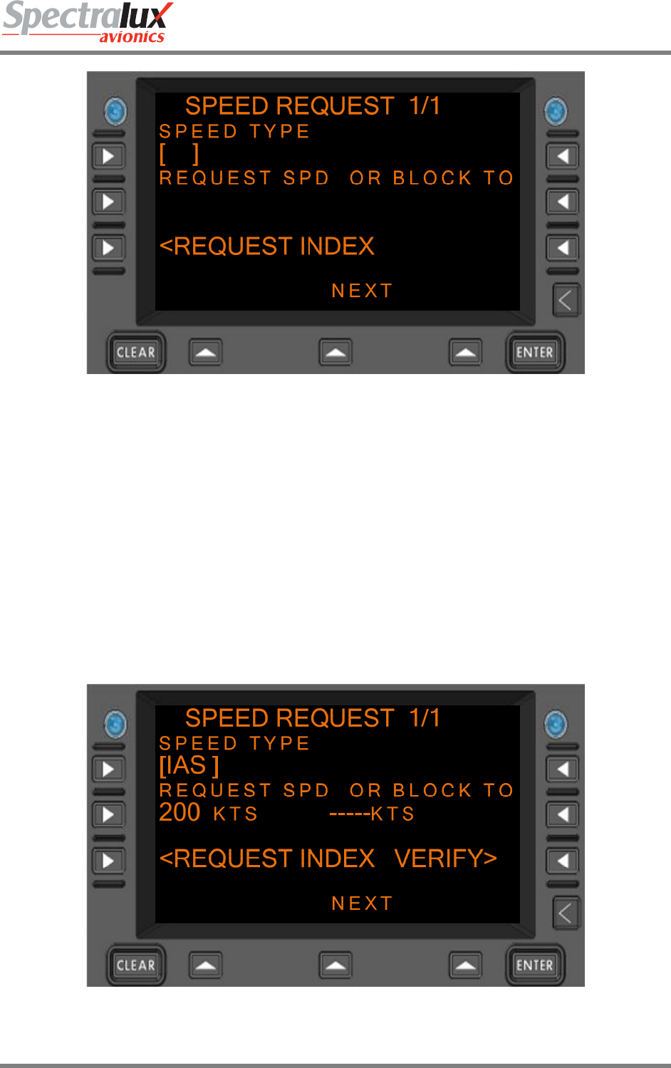
An example of the speed request page with the ‘REQUEST SPD’ Line Field filled in and the ‘VERIFY’
prompt displayed is in Figure 7.1.7-3
Figure 7.1.7-3 SPEED REQUEST Menu, Verify Prompt Display
Dlink+CPDLC Users Guide
Document Number: UG-14114 Rev. - Page 125 of 201
7.1.8 CPDLC – Route Mod Request Menu
The ROUTE MOD REQUEST Menu provides a means by which the operator may request a route
modification. The content and operational features of this menu change depending on the ATN
Operational Mode, as discussed in this Section. For information on ATN Operational Modes, see Sections
7.1.1 and 7.3.
PAGE NAVIGATION:
A. ► L1 Line Select Key from the CPDLC INDEX menu (See section 7.1.1) then ► R2 Line
Select Key from the REQUEST INDEX (See section 7.1.5)
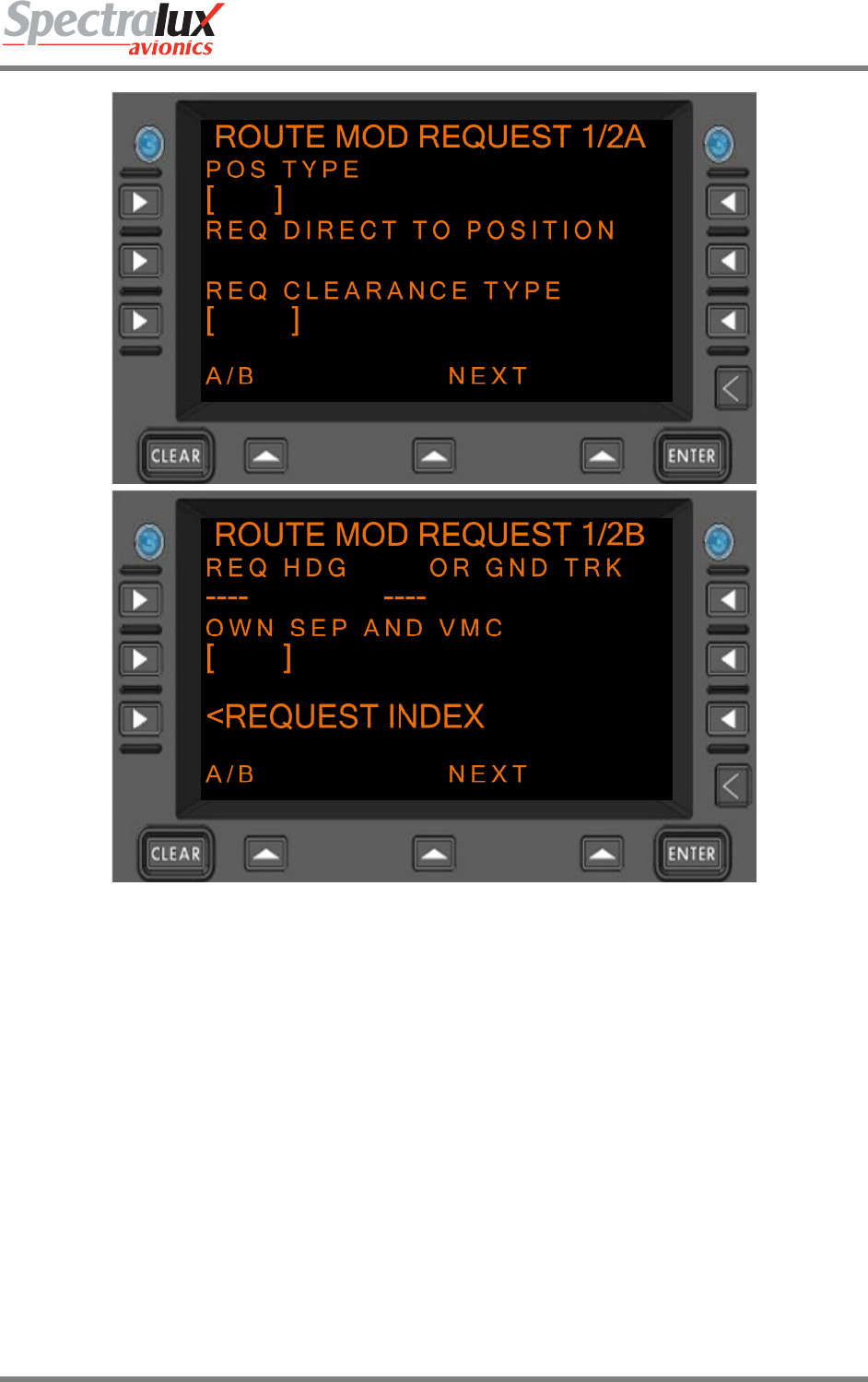
7.1.8.1 ROUTE MOD REQUEST Menu, Link 2000 Operational Mode
When configured for LINK 2000 Mode the following Route Modification Request is valid:
• Request Direct To Position (POS TYPE and REQ DIRECT TO POSITION fields must contain
valid values)
Figure 7.1.8-1 ROUTE MOD REQUEST Menu Page 1 (Menus A and B), LINK 2000
Dlink+CPDLC Users Guide
Document Number: UG-14114 Rev. - Page 126 of 201
Figure 7.1.8-2 ROUTE MOD REQUEST Menu Page 2 (Menus A and B), LINK 2000
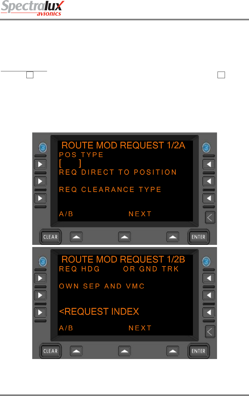
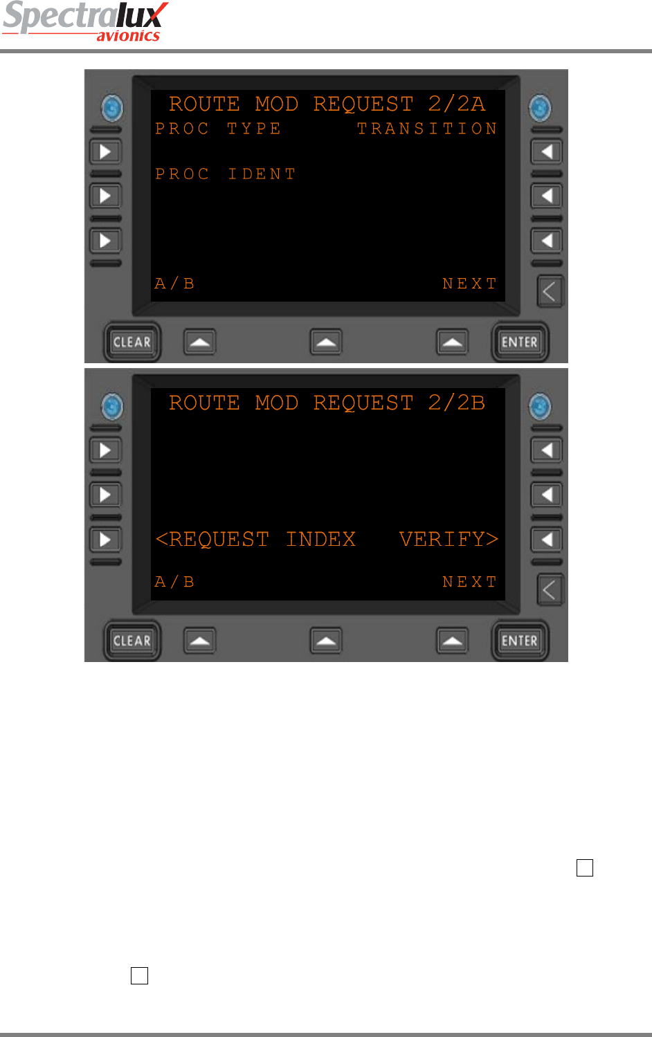
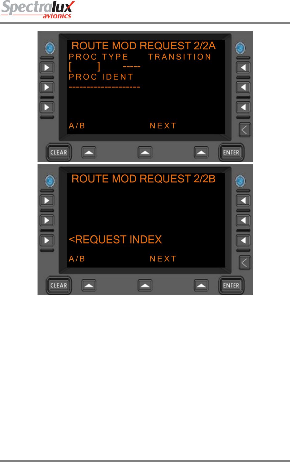
7.1.8.2 ROUTE MOD REQUEST Menu, RTCA DO 280 B Operational Mode
When configured for RTCA DO 280B Mode the following Route Modification Requests are valid:
• Request Direct To Position (POS TYPE and REQ DIRECT TO POSITION fields must contain
valid values)
• Request Procedure (PROC TYPE, TRANSITION, and PROC IDENT fields must contain valid
values)
• Request Clearance (REQ CLEARANCE TYPE field must be selected by pressing the L3 line
select key on page 1/2A)
• Request Heading (REQ HDG field must contain a valid heading)
• Request Track (OR GND TRK must contain a valid track)
• Request To Maintain Own Separation and VMC (OWN SEP AND VMC field must be selected by
pressing the L2 line select key on page 1/2B)
Dlink+CPDLC Users Guide
Document Number: UG-14114 Rev. - Page 127 of 201
Figure 7.1.8-3 ROUTE MOD REQUEST Menu Page 1 (Menus A and B), DO 280B
Dlink+CPDLC Users Guide
Document Number: UG-14114 Rev. - Page 128 of 201
Figure 7.1.8-4 ROUTE MOD REQUEST Menu Page 1 (Menus A and B), DO 280B
DIRECT TO POSITION Format:
1. When associated Position Type field is set to NAVAID, the following entry is
valid:
a. Format: AAAA
b. Range: 0-9, A-Z (1- 4 Characters)
2. When associated Position Type field is set to FIX (FixName), the following
entries are valid:
• Format: AAAAA
• Range: 0-9, A-Z (1-5 Characters)
3. When associated Position Type field is set to AIRPORT (airport), the following
entry is valid:
a. Format: AAAA
b. Range: 0-9, A-Z (4 characters)
4. When associated Position Type field is set to LAT/LON (latitudeLongitude),

Dlink+CPDLC Users Guide
Document Number: UG-14114 Rev. - Page 129 of 201
the following entries are valid:
a. Format: ADDMMSS/BDDDMMSS
b. Where: “A” is either N or S
“B” is either E or W
“DD” is a numerical entry representing geographical
latitude
“DDD” is a numerical entry representing geographical
longitude
“MM” is a numerical entry representing geographical
minutes.
“SS” is a numerical entry representing geographical
seconds.
c. Range: “DD” is 00-89
“DDD” is 000-179
“MM” is 0-59
“SS” is 0-59
5. When associated Position Type field is set to PBD-NAV
(PlaceBearingDistance using NAVAID), the following entries are valid:
a) Format: AAAA/XXXT/YYY (Where “AAAAA” is validated
using the “NAVAID” entry requirements in this section).
b) Where: “A” is an alpha-numeric entry representing a navaid.
“X” is a numerical entry representing degrees
“T” is an optional entry to indicate the bearing is
references to True North
“Y” is a numerical entry representing distance
.
c) Range: “A” is 0-9, A-Z
“X” is 000 - 360
“Y” is 1-250 (This restriction could be user defined)
6. When associated Position Type field is set to PBD-FIX (PlaceBearingDistance
using FIX), the following entries are valid:
a) Format: AAAAA/XXXT/YYY (Where “AAAAA” is validated
using the “FIX” entry requirements in this section).
b) Where: “A” is an alpha-numeric entry representing a fix.
“X” is a numerical entry representing degrees
“T” is an optional entry to indicate the bearing is
references to True North
“Y” is a numerical entry representing distance
.
c) Range: “A” is 0-9, A-Z
“X” is 000 - 360
“Y” is 1-250 (This restriction could be user defined)
Dlink+CPDLC Users Guide
Document Number: UG-14114 Rev. - Page 130 of 201
REQ HDG
OR
GND TRK
Format: NNNT Where “N” is a numerical entry
“T” indicates the entry is referenced to True North and is optional.
Range: 1-360 (3 numerical characters, with an optional 4th for the letter “T”)
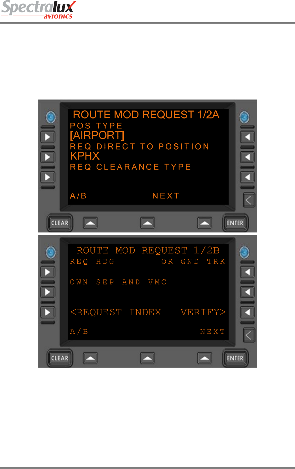
An example of the Route Mod Request page (LINK 2000) with the ‘POS TYPE’ and ‘REQ DIRECT TO
POSITION’ fields entered and the ‘VERIFY’ prompt shown on Route Mod menu 1B-Page is shown in
Figure 7.1.8-5.
Figure 7.1.8-5 ROUTE MOD REQUEST Menu, Verify Prompt Displayed
Dlink+CPDLC Users Guide
Document Number: UG-14114 Rev. - Page 131 of 201
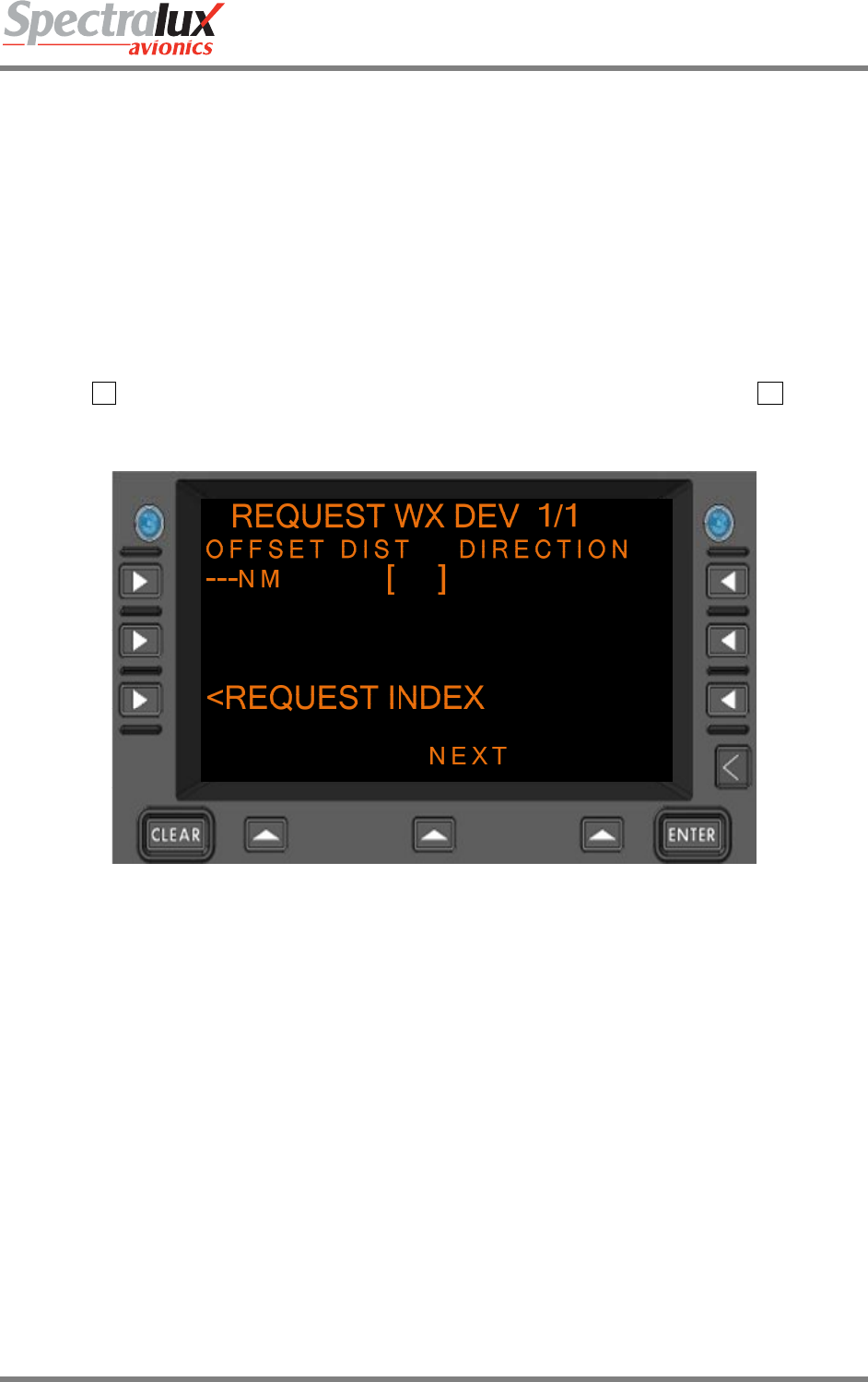
7.1.9 CPDLC – Request Weather Deviation Menu
The REQUEST WX DEV (Request Weather Deviation) Menu provides a means by which the operator
may request a Route Modification due to weather. The content and operational features of this menu are
identical, regardless of the ATN Operational Mode.
When configured for LINK 2000 or RTCA DO 280B Mode the following Weather Deviation Request is
valid:
• Request Weather Deviation from Route (OFFSET DIST and DIRECTION fields must contain valid
values)
An example of a blank REQUEST WX DEV Menu (no entries made) is shown in Figure 7.1.9-1
PAGE NAVIGATION:
A. ► L1 Line Select Key from the CPDLC INDEX Menu (See section 7.1.1) then ► R3 Line
Select Key from the REQUEST INDEX Menu (See section 7.1.5)
Figure 7.1.9-1 WEATHER DEVIATION REQUEST Menu
OFFSET DIST Format:
1. When configured for English standard units, the following entry is valid
(distanceSpecifiedNm):
a) Format: NNN
b) Where: “N” is a numerical entry
c) Range: 1-250
d) Units: NM
2. When configured for Metric units, the following entry is valid
(distanceSpecifiedKm):
a) Format: NNN
b) Where: “N” is a numerical entry
c) Range: 1-500
d) Units: KM
Dlink+CPDLC Users Guide
Document Number: UG-14114 Rev. - Page 132 of 201
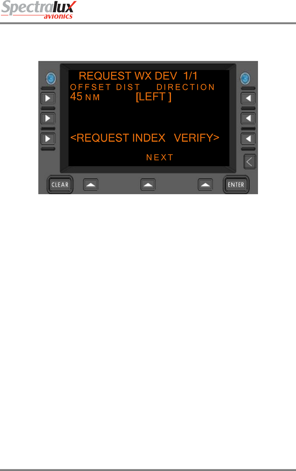
An example of the WEATHER DEVIATION REQUEST Menu with the ‘OFFSET DIST’ and ‘DIRECTION’
fields filled in and the ‘VERIFY’ prompt is shown in Figure 7.1.9-2
Figure 7.1.9-2 WEATHER DEVIATION REQUEST, Verify Prompt Displayed
Dlink+CPDLC Users Guide
Document Number: UG-14114 Rev. - Page 133 of 201
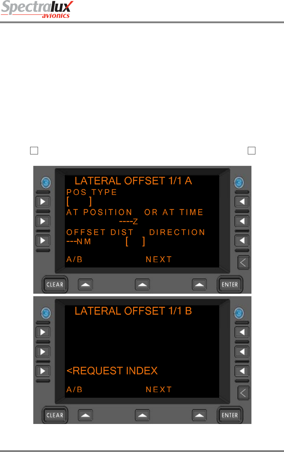
7.1.10 CPDLC – Lateral Offset Menu
The LATERAL OFFSET Menu is only available when in DO 280B ATN Operational mode. This menu
provides a means by which the operator may request a lateral offset.
When configured for RTCA DO 280B Mode the following Lateral Offset Requests are valid:
• Request Lateral Offset from Route (OFFSET DIST and DIRECTION fields must contain valid
values)
• At Position Request Lateral Offset from Route (POS TYPE, AT POSITION, OFFSET DIST, and
DIRECTION fields must contain valid values)
• At Time Request Lateral Offset from Route (OR AT TIME, OFFSET DIST, and DIRECTION fields
must contain valid values)
An example of the blank LATERAL OFFSET Menu (no entries made) is shown in Figure 7.1.10-1
PAGE NAVIGATION:
A. ► L1 Line Select Key from the CPDLC INDEX Menu (See section 7.1.1) then ► L2 Line
Select Key from the REQUEST INDEX menu (See section 7.1.5)
Figure 7.1.10-1 LATERAL OFFSET REQUEST Menu

Dlink+CPDLC Users Guide
Document Number: UG-14114 Rev. - Page 134 of 201
OFFSET DIST Format:
1. When configured for English standard units, the following entry is valid
(distanceSpecifiedNm):
a) Format: NNN
b) Where: “N” is a numerical entry
c) Range: 1-250
d) Units: NM
2. When configured for Metric units, the following entry is valid
(distanceSpecifiedKm):
e) Format: NNN
f) Where: “N” is a numerical entry
g) Range: 1-500
h) Units: KM
AT POSITION Format:
1. When associated Position Type field is set to NAVAID (Navaid), the following
entry is valid:
c. Format: AAAA
d. Range: 0-9, A-Z (1- 4 Characters)
2. When associated Position Type field is set to FIX (FixName), the following
entries are valid:
• Format: AAAAA
• Range: 0-9, A-Z (1-5 Characters)
3. When associated Position Type field is set to AIRPORT (airport), the
following entry is valid:
c. Format: AAAA
d. Range: 0-9, A-Z (4 characters)
4. When associated Position Type field is set to LAT/LON (latitudeLongitude),
the following entries are valid:
d. Format: ADDMMSS/BDDDMMSS
e. Where: “A” is either N or S
“B” is either E or W
“DD” is a numerical entry representing geographical
latitude
“DDD” is a numerical entry representing geographical
longitude
“MM” is a numerical entry representing geographical
minutes.
“SS” is a numerical entry representing geographical
seconds.
f. Range: “DD” is 00-89
“DDD” is 000-179

Dlink+CPDLC Users Guide
Document Number: UG-14114 Rev. - Page 135 of 201
“MM” is 0-59
“SS” is 0-59
5. When associated Position Type field is set to PBD-NAV
(PlaceBearingDistance using NAVAID), the following entries are valid:
d) Format: AAAA/XXXT/YYY (Where “AAAAA” is validated
using the “NAVAID” entry requirements in this section).
e) Where: “A” is an alpha-numeric entry representing a navaid.
“X” is a numerical entry representing degrees
“T” is an optional entry to indicate the bearing is
references to True North
“Y” is a numerical entry representing distance
.
f) Range: “A” is 0-9, A-Z
“X” is 000 - 360
“Y” is 1-250 (This restriction could be user defined)
6. When associated Position Type field is set to PBD-FIX
(PlaceBearingDistance using FIX), the following entries are valid:
d) Format: AAAAA/XXXT/YYY (Where “AAAAA” is
validated using the “FIX” entry requirements in this
section).
e) Where: “A” is an alpha-numeric entry representing a fix.
“X” is a numerical entry representing
degrees
“T” is an optional entry to indicate the bearing is
references to True North
“Y” is a numerical entry representing distance
.
f) Range: “A” is 0-9, A-Z
“X” is 000 - 360
“Y” is 1-250 (This restriction could be user defined)
AT TIME Format: HHMM
HH = hours
MM = minutes
Hours range: 00-23
Minutes range: 00-59
An example of the Lateral Offset Menu with the ‘POS TYPE’, ‘AT POSITION’, ‘OFFSET DIST’, and
‘DIRECTION’ fields filled in and the ‘VERIFY’ prompt is shown in Figure 7.1.10-2.

Dlink+CPDLC Users Guide
Document Number: UG-14114 Rev. - Page 136 of 201
Figure 7.1.10-2 LATERAL OFFSET REQUEST Menu, Verify Prompt Displayed

Dlink+CPDLC Users Guide
Document Number: UG-14114 Rev. - Page 137 of 201
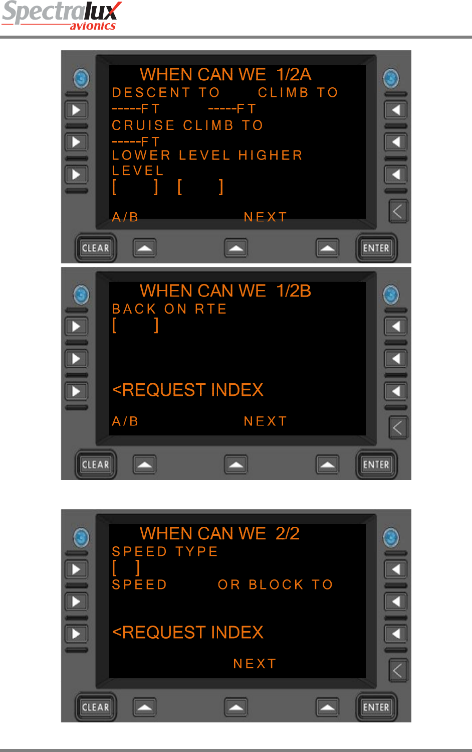
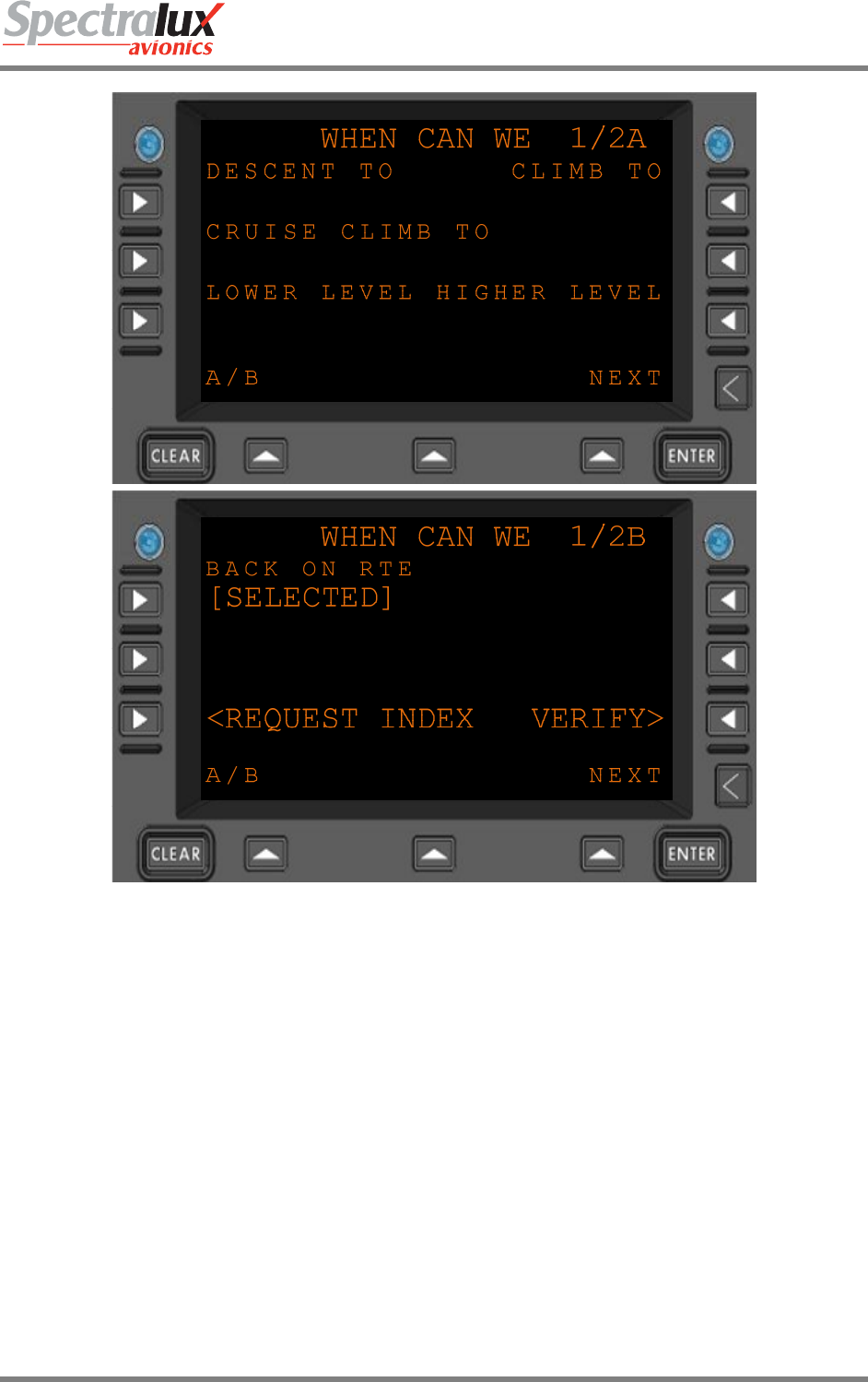
7.1.11 CPDLC – When Can We Menu
The WHEN CAN WE Menu is only available when in DO 280B ATN Operational mode (see Section
7.1.1). This menu provides a means by which the operator may request when it is possible to adjust the
current speed, vertical location, or lateral location of the aircraft.
When configured for RTCA DO 280B Mode the following When Can We Requests are valid:
• When Can We Expect Speed (SPEED TYPE and SPEED fields must contain valid values)
• When Can We Expect Speed Range (SPEED TYPE, SPEED, and OR BLOCK TO fields must
contain valid values)
• When Can We Expect Back On Route (BACK ON RTE field must be selected by pressing the L1
line select key on page 1/2B)
• When Can We Expect Lower Level (LOWER LEVEL field must be selected by pressing the L3
line select key on page 1/2A)
• When Can We Expect Higher Level (HIGHER LEVEL field must be selected by pressing the R3
line select key on page 1/2A)
• When Can We Expect Cruise Climb to Level (CRUISE CLIMB TO field must contain a valid level)
• When Can We Expect Climb to Level (CLIMB TO field must contain a valid level)
• When Can We Expect Descent to Level (DESCENT TO field must contain a valid level)
An example of the blank When Can We Menu (no entries made) is shown in Figure 7.1.11-2
PAGE NAVIGATION:
A. ► L1 Line Select Key from the CPDLC INDEX Menu (See section 7.1.1) then ► L3 Line
Select Key from the REQUEST INDEX Menu (See section 7.1.5)
Dlink+CPDLC Users Guide
Document Number: UG-14114 Rev. - Page 138 of 201
Figure 7.1.11-1 WHEN CAN WE REQUEST Menu Page 1 (Menus A and B)
Figure 7.1.11-2 WHEN CAN WE REQUEST Menu Page 2

Dlink+CPDLC Users Guide
Document Number: UG-14114 Rev. - Page 139 of 201
DECENT TO
CRUISE CLIMB TO
CLIMB TO
Format:
1. When configured for English-standard units, the following entry is
valid (LevelFeet):
a) Format: NNNNN
b) Where: “N” is a numerical entry
c) Range: -600 – 70000 (1 – 5 characters)
d) Units: FT
2. When configured for English-standard units, the following entry is
valid (LevelFlightLevel):
a) Format: FLNNN
b) Where: “N” is a numerical entry
c) Range: 030 – 700 (5 characters including “FL”)
d) Units: N/A
3. When configured for Metric units, the following entry is valid
(LevelMeters):
a) Format: NNNNN
b) Where: “N” is a numerical entry
c) Range: -30 – 25000 (1 – 5 characters)
d) Units: M
4. When configured for Metric units, the following entry is valid
(LevelFlightLevelMeters):
a) Format: FLNNN
b) Where: “N” is a numerical entry
c) Range: 10 – 250 (5 characters, including “FL”)
d) Units: M
An example of the When Can We request page with the ‘BACK ON RTE’ field filled in and the ‘VERIFY’
prompt is shown in Figure 7.1.11-3.
Dlink+CPDLC Users Guide
Document Number: UG-14114 Rev. - Page 140 of 201
Figure 7.1.11-3 WHEN CAN WE REQUEST Menu, Verify Prompt Displayed
Dlink+CPDLC Users Guide
Document Number: UG-14114 Rev. - Page 141 of 201
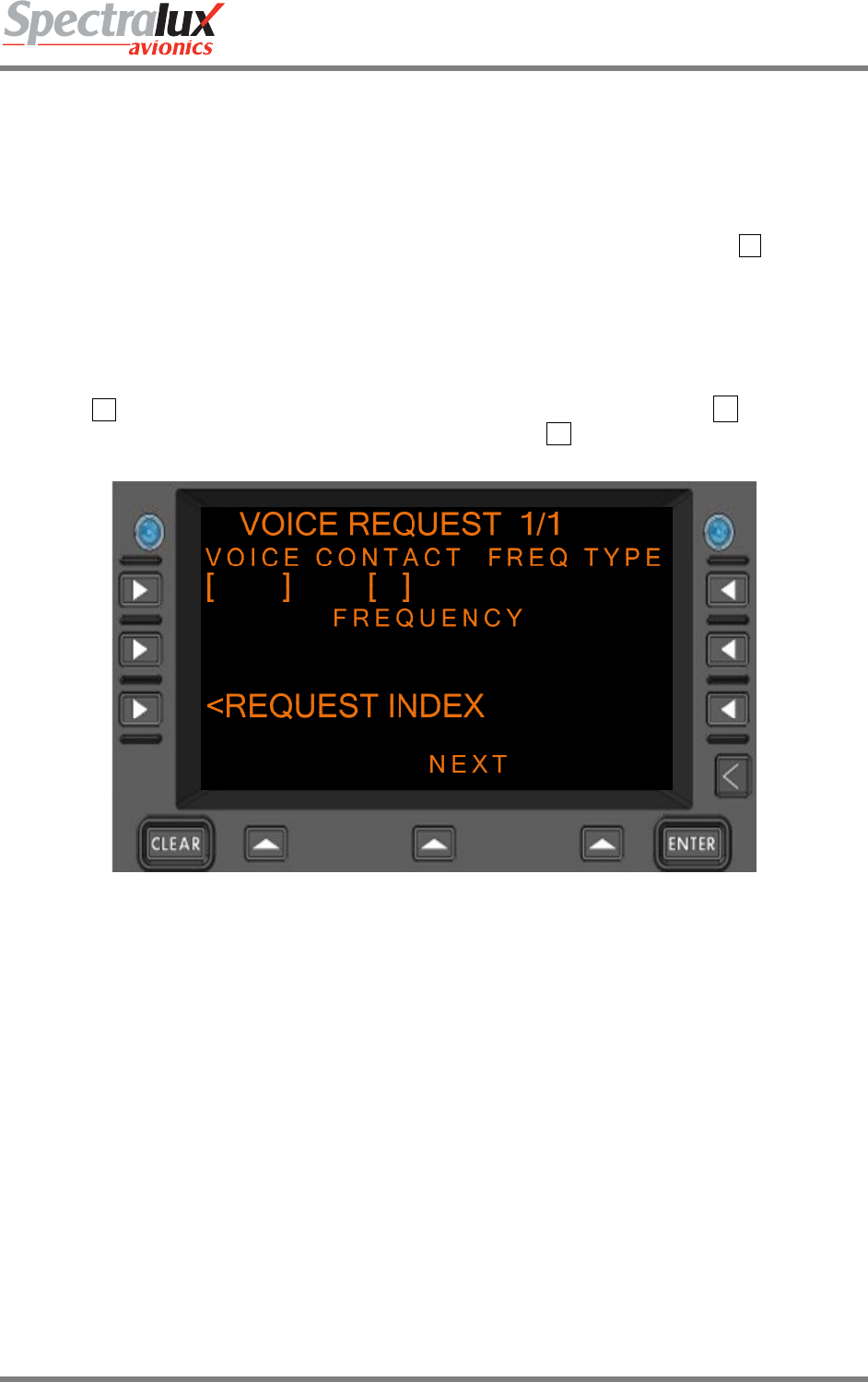
7.1.12 CPDLC – Voice Request Menu
The VOICE REQUEST Menu is only available when in DO 280B ATN Operational mode (see Section
7.1.1). This menu provides a means by which the operator may request voice contact.
When configured for RTCA DO 280B Mode the following Voice Requests are valid:
• Request Voice Contact (VOICE CONTACT field must be selected by pressing the L1 line select
key)
• Request Voice Contact on Frequency (FREQ_TYPE and FREQUENCY must contain valid
values)
An example of the blank Voice Request Menu (no entries made) is in Figure 7.1.12-1
PAGE NAVIGATION:
A. ► L1 Line Select Key from the CPDLC INDEX Menu (See section 7.1.1) ► ↓ Function Key
from the REQUEST INDEX Menu (See section 7.1.5) ► R1 Line Select Key from the
REQUEST INDEX page B Menu (See section 7.1.5)
Figure 7.1.12-1 VOICE REQUEST Menu
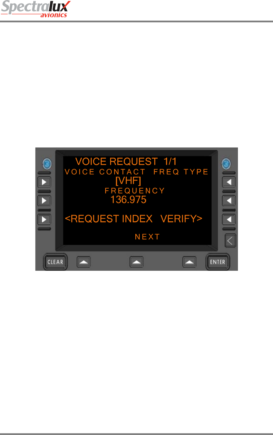
FREQUENCY Format:
1. If the Frequency Type is set to 0 (HF):
a) Format: NNNNN
b) Where: “N” is a numerical entry.
c) Range: 2850 – 28000
d) Units: kHz
2. If the Frequency Type is set to 1 (VHF):
a) Format: NNN.NNN
b) Where: “N” is a numerical entry.
c) Range: 118.00-136.990
d) Units: MHz
3. If the Frequency Type is set to 2 (UHF):
Dlink+CPDLC Users Guide
Document Number: UG-14114 Rev. - Page 142 of 201
a) Format: NNN.NNN
b) Where: “N” is a numerical entry.
c) Range: 225.000 - 399.975
d) Units: MHz
4. If the Frequency Type is set to 3 (SAT):
a) Format: NNNNNNNNNNNN
b) Where: “N” is a numerical entry.
c) Range: Numerical string representing a 12-digit telephone number
An example of the Voice request page with the ‘FREQ TYPE’ and ‘FREQUENCY’ fields filled in and the
‘VERIFY’ prompt is shown in Figure 7.1.12-2
Figure 7.1.12-2 VOICE REQUEST Menu, Verify Prompt Displayed
Dlink+CPDLC Users Guide
Document Number: UG-14114 Rev. - Page 143 of 201
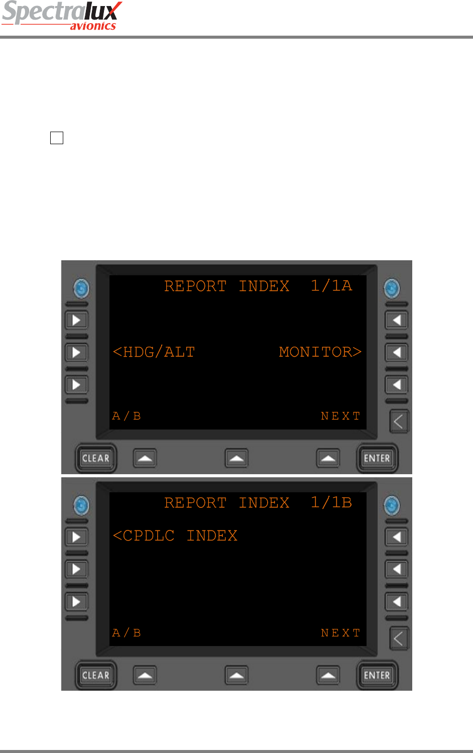
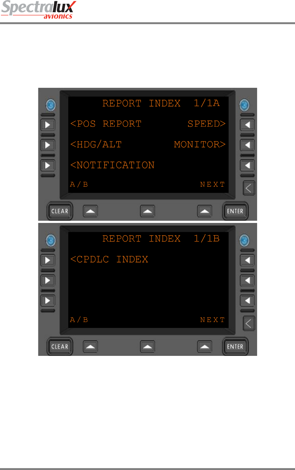
7.1.13 CPDLC – Report Index Menu
The REPORT INDEX Menu provides access to the CPDLC Report Menus. The content and operational
features of this menu change depending on the ATN Operational Mode, as discussed in this Section. For
information on ATN Operational Modes, see Sections 7.1.1 and 7.3.
PAGE NAVIGATION:
A. ► L2 menu key from the CPDLC INDEX menu (See section 7.1.1)
7.1.13.1 Report Index Menu, Link 2000 Operational Menu
When in LINK 2000 Mode the REPORT INDEX Menu is limited to the following reports:
• HDG/ALT (Heading/Altitude)
• MONITOR
Figure 7.1.13-1 REPORT INDEX Menu (Menus A and B), LINK 2000
Dlink+CPDLC Users Guide
Document Number: UG-14114 Rev. - Page 144 of 201
7.1.13.2 Report Index Menu, RTCA DO 280 Operational Mode
The REPORT Menu provides the ability to access the Position Report Menu (see section 7.1.16), Speed
Report Menu (see section 7.1.17), Heading/Altitude Report Menu (see section 7.1.14), Monitoring Report
Menu (see section 7.1.15), and Notification Report Menu (see section 7.1.18). Each of these menus can
be selected using the corresponding Line Select Keys.
Figure 7.1.13-2 REPORT INDEX Menu (Menus A and B), DO 280B
Dlink+CPDLC Users Guide
Document Number: UG-14114 Rev. - Page 145 of 201
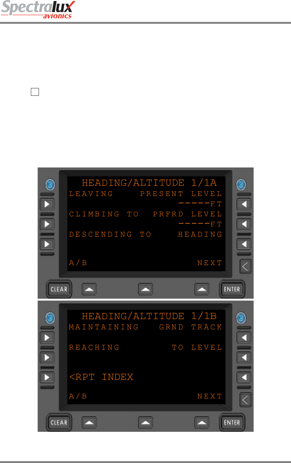
7.1.14 CPDLC – Heading/Altitude Report Menu
The Heading/Altitude Report Menu provides a means by which the operator may report changes to the
current vertical location of the aircraft as well as changes to the aircraft heading or track. The content and
operational features of this menu change depending on the ATN Operational Mode, as discussed in this
Section. For information on ATN Operational Modes, see Sections 7.1.1 and 7.3.
PAGE NAVIGATION:
A. ► L2 from the REPORT INDEX Menu (see Section 7.1.1)
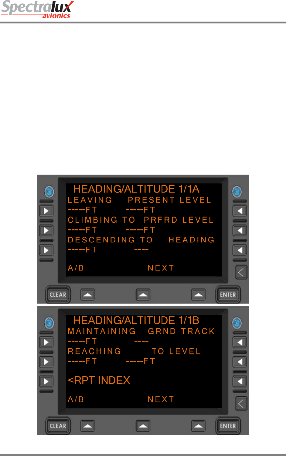
7.1.14.1 HEADING/ALTITUDE Report Menu, Link 2000 Operational Mode
When configured for LINK 2000 Mode the following Heading/Altitude Reports are valid:
• Present Level (PRESENT LEVEL field must contain a valid level)
• Preferred Level (PRFRD LEVEL field must contain a valid level)
Figure 7.1.14-1 HEADING/ALTITUDE Menu (Menus A and B), LINK 2000
Dlink+CPDLC Users Guide
Document Number: UG-14114 Rev. - Page 146 of 201
7.1.14.2 Heading/Altitude Report Menu, RTCA DO 280 B Operational Mode
When configured for RTCA DO 280B Mode the following Heading/Altitude Reports are valid:
• Leaving Level (LEAVING field must contain a valid level)
• Climbing to Level (CLIMBING TO field must contain a valid level)
• Descending to Level (DESCENDING TO field must contain a valid level)
• Present Level (PRESENT LEVEL field must contain a valid level)
• Present Heading (HEADING field must contain a valid heading)
• Present Ground Track (GRND TRACK field must contain a valid track)
• Maintaining Level (MAINTAINING field must contain a valid level)
• Reaching Level (REACHING field must contain a valid level)
• Reaching Block Level (REACHING and TO LEVEL fields must contain valid levels)
• Preferred Level (PRFRD LEVEL field must contain a valid level)
Figure 7.1.14-2 HEADING/ALTITUDE Menu (Menus A and B), DO 280B

Dlink+CPDLC Users Guide
Document Number: UG-14114 Rev. - Page 147 of 201
LEAVING
CLIMBING TO
DESCENDING TO
PRESENT LEVEL
PRFRD LEVEL
MAINTAINING
REACHING
TO LEVEL
Format:
5. When configured for English-standard units, the following entry is
valid (LevelFeet):
a) Format: NNNNN
b) Where: “N” is a numerical entry
c) Range: -600 – 70000 (1 – 5 characters)
d) Units: FT
6. When configured for English-standard units, the following entry is
valid (LevelFlightLevel):
a) Format: FLNNN
b) Where: “N” is a numerical entry
c) Range: 030 – 700 (5 characters including “FL”)
d) Units: N/A
7. When configured for Metric units, the following entry is valid
(LevelMeters):
a) Format: NNNNN
b) Where: “N” is a numerical entry
c) Range: -30 – 25000 (1 – 5 characters)
d) Units: M
8. When configured for Metric units, the following entry is valid
(LevelFlightLevelMeters):
a) Format: FLNNN
b) Where: “N” is a numerical entry
c) Range: 10 – 250 (5 characters, including “FL”)
d) Units: M
GRND TRACK Format: NNNT Where “N” is a numerical entry
“T” indicates the entry is referenced to True North and is optional.
Range: 1-360 (3 numerical characters, with an optional 4th for the letter
“T”)
HEADING Format: NNNT Where “N” is a numerical entry
“T” indicates the entry is referenced to True North and is optional.
Range: 1-360 (3 numerical characters, with an optional 4th for the letter
“T”)
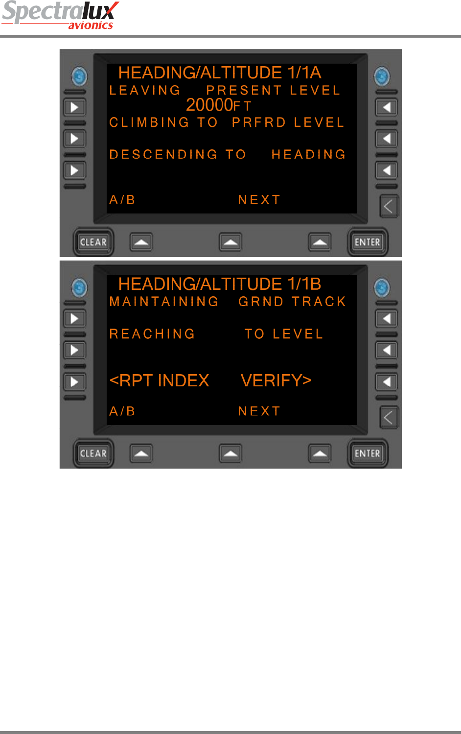
An example of the Heading/Altitude report page with the ‘PRESENT LEVEL’ field filled in and the
‘VERIFY’ prompt is shown in Figure 7.1.14-3
Dlink+CPDLC Users Guide
Document Number: UG-14114 Rev. - Page 148 of 201
Figure 7.1.14-3 HEADING/ALTITUDE Menu, Verify Prompt Displayed
Dlink+CPDLC Users Guide
Document Number: UG-14114 Rev. - Page 149 of 201
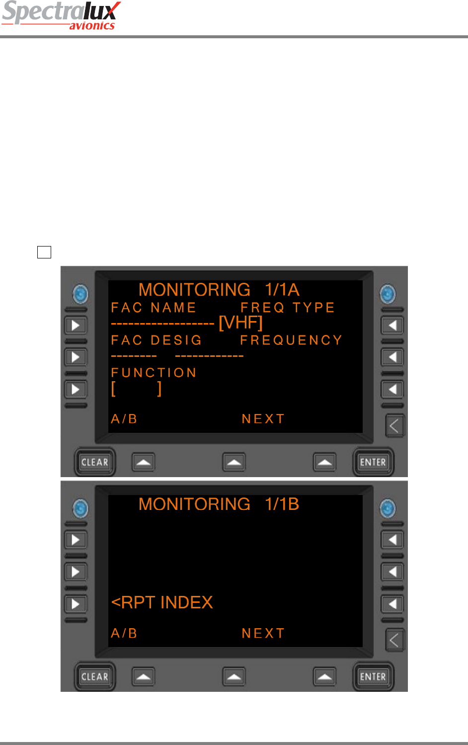
7.1.15 CPDLC – Monitoring Report Menu
The MONITORING Menu provides a means to notify ATC that the radios have been tuned to the
assigned unit and frequency. An example of the use of this page may be: when receiving an uplink that
requests a unit/frequency change, the operator responds with a “WILCO” and sets the radios as
assigned. Then the operator may send a separate message from the MONITORING page indicating that
they have complied with the request. The content and operational features of this menu are identical,
regardless of the ATN Operational Mode.
When configured for LINK 2000 or RTCA DO 280B Mode the following Monitoring Report is valid:
• Monitoring UnitName Frequency (FAC NAME, FAC DESIG, FUNCTION, FREQ TYPE, and
FREQUENCY must contain valid values)
An example of a blank MONITORING Menu (no entries made) is shown in Figure 7.1.15-1
PAGE NAVIGATION:
A. R2 Line Select Key from the REPORT INDEX Menu (see Section 7.1.1).
Figure 7.1.15-1 MONITORING Menu (Menus A and B)

Dlink+CPDLC Users Guide
Document Number: UG-14114 Rev. - Page 150 of 201
FAC NAME Format: AAAAAAAAAAAAAAAAAA Where “A” is an alpha-entry
Range: A-Z (3 – 18 characters)
FAC DESIG Format: AAAAAAAA Where: “A” is an alpha-numeric entry
Range: A-Z, 0-9 (4 – 8 characters)
FREQUENCY Format:
1. If the Frequency Type is set to 0 (HF):
a. Format: NNNNN
b. Where: “N” is a numerical entry.
c. Range: 2850 – 28000
d. Units: kHz
2. If the Frequency Type is set to 1 (VHF):
a. Format: NNN.NNN
b. Where: “N” is a numerical entry.
c. Range: 118.00-136.990
d. Units: MHz
3. If the Frequency Type is set to 2 (UHF):
a. Format: NNN.NNN
b. Where: “N” is a numerical entry.
c. Range: 225.000 - 399.975
d. Units: MHz
4. If the Frequency Type is set to 3 (SAT):
a. Format: NNNNNNNNNNNN
b. Where: “N” is a numerical entry.
c. Range: Numerical string representing a 12-digit telephone number
d. Units: N/A
An example of the Monitoring Report Menu with the ‘FAC NAME’, ‘FAC DESIG’, ‘FUNCTION’, ‘FREQ
TYPE’, and ‘FREQUENCY’ fields filled in and the ‘VERIFY’ prompt is shown in Figure 7.1.15-2
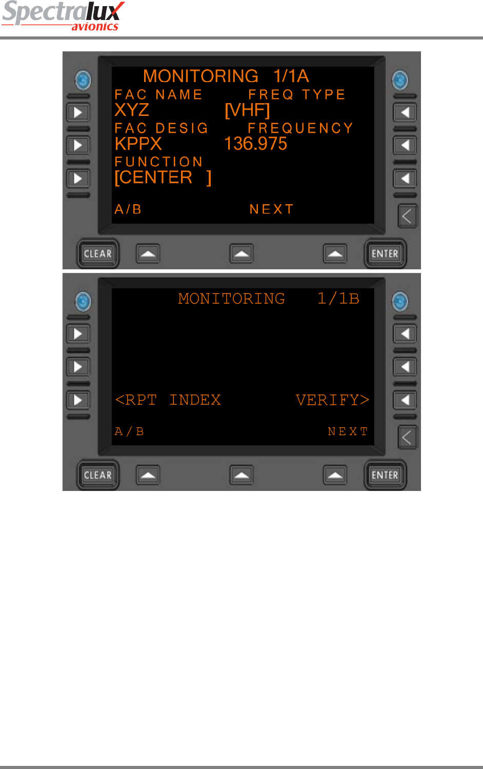
Dlink+CPDLC Users Guide
Document Number: UG-14114 Rev. - Page 151 of 201
Figure 7.1.15-2 MONITORING Menu (Menus A and B), Verify Prompt Displayed
Dlink+CPDLC Users Guide
Document Number: UG-14114 Rev. - Page 152 of 201
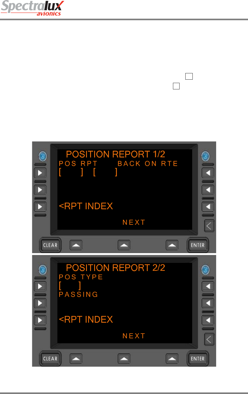
7.1.16 CPDLC – Position Report Menu
The POSITION REPORT Menu is only available when in DO 280B ATN Operational mode (see Section
7.1.16).The Position Report Menu provides a means by which the operator may report current aircraft
position.
When configured for RTCA DO 280B Mode the following Position Reports are valid:
• Passing Position (POS TYPE and PASSING fields must contain valid values)
• Back On Route (BACK ON RTE field must be selected by pressing the R1 line select key)
• Position Report (POS RPT field must be selected by pressing the L1 line select key)
An example of the blank Position Report Menu (no entries made) is shown in Figure 7.1.16-1
PAGE NAVIGATION:
1. ► L2 Line Select key from the CPDLC INDEX Menu (See section 7.1.1) then ► L1 Line
Select Key from the REPORT INDEX Menu (See section 7.1.13)
Figure 7.1.16-1 POSITION REPORT Menu (Menus A and B), DO 280B

Dlink+CPDLC Users Guide
Document Number: UG-14114 Rev. - Page 153 of 201
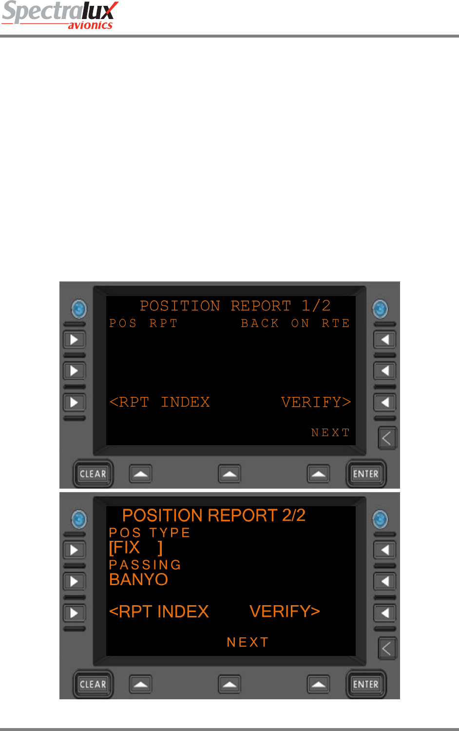
PASSING Format:
1. When associated Position Type field is set to NAVAID (Navaid), the following
entry is valid:
a. Format: AAAA
b. Range: 0-9, A-Z (1- 4 Characters)
2. When associated Position Type field is set to FIX (FixName), the following
entries are valid:
a. Format: AAAAA
b. Range: 0-9, A-Z (1-5 Characters)
3. When associated Position Type field is set to AIRPORT (airport), the following
entry is valid:
a. Format: AAAA
b. Range: 0-9, A-Z (4 characters)
4. When associated Position Type field is set to LAT/LON (latitudeLongitude), the
following entries are valid:
a. Format: ADDMMSS/BDDDMMSS
b. Where: “A” is either N or S
“B” is either E or W
“DD” is a numerical entry representing geographical latitude
“DDD” is a numerical entry representing geographical
longitude
“MM” is a numerical entry representing geographical
minutes.
“SS” is a numerical entry representing geographical
seconds.
c. Range: “DD” is 00-89
“DDD” is 000-179
“MM” is 0-59
“SS” is 0-59
5. When associated Position Type field is set to PBD-NAV (PlaceBearingDistance
using NAVAID), the following entries are valid:
a) Format: AAAA/XXXT/YYY (Where “AAAAA” is validated using the “NAVAID”
entry requirements in this section).
b) Where: “A” is an alpha-numeric entry representing a navaid.
“X” is a numerical entry representing degrees
“T” is an optional entry to indicate the bearing is references
to True North
“Y” is a numerical entry representing distance
.
c) Range: “A” is 0-9, A-Z
“X” is 000 - 360
“Y” is 1-250 (This restriction could be user defined)
6. When associated Position Type field is set to PBD-FIX (PlaceBearingDistance
Dlink+CPDLC Users Guide
Document Number: UG-14114 Rev. - Page 154 of 201
using FIX), the following entries are valid:
a) Format: AAAAA/XXXT/YYY (Where “AAAAA” is validated using the “FIX”
entry requirements in this section).
b) Where: “A” is an alpha-numeric entry representing a fix.
“X” is a numerical entry representing degrees
“T” is an optional entry to indicate the bearing is references
to True North
“Y” is a numerical entry representing distance .
c) Range: “A” is 0-9, A-Z
“X” is 000 - 360
“Y” is 1-250 (This restriction could be user defined)
An example of the Position Report Menu with the ‘POS TYPE’ and ‘PASSING’ fields filled in and the
‘VERIFY’ prompt is shown in Figure 7.1.16-2
Figure 7.1.16-2 POSITION REPORT Menu (Menus A and B), Verify Prompt Displayed
Dlink+CPDLC Users Guide
Document Number: UG-14114 Rev. - Page 155 of 201
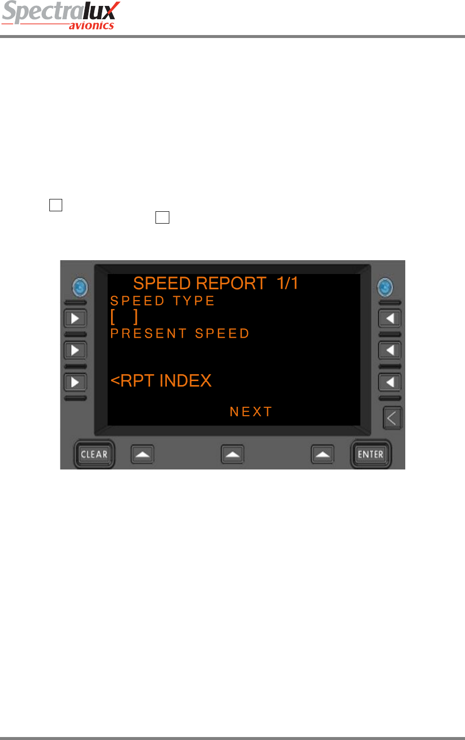
7.1.17 CPDLC – Speed Report Menu
The Speed Report Menu is only available when in DO 280B ATN Operational mode (see Section
7.1.1).The Speed Report Menu provides a means by which the operator may report current aircraft
speed.
When configured for RTCA DO 280B Mode the following Speed Report is valid:
• Present Speed (SPEED TYPE and PRESENT SPEED fields must contain valid values)
An example of the blank Speed Report Menu (no entries made) is shown in Figure 7.1.17-1
PAGE NAVIGATION:
A. ► L2 Line Select Key from the CPDLC INDEX Menu (See section7.1.1 Error! Reference
source not found.) then ► R1 Line Select Key from the REPORT INDEX Menu (See section
7.1.13)
Figure 7.1.17-1 SPEED REPORT Menu, DO 280B
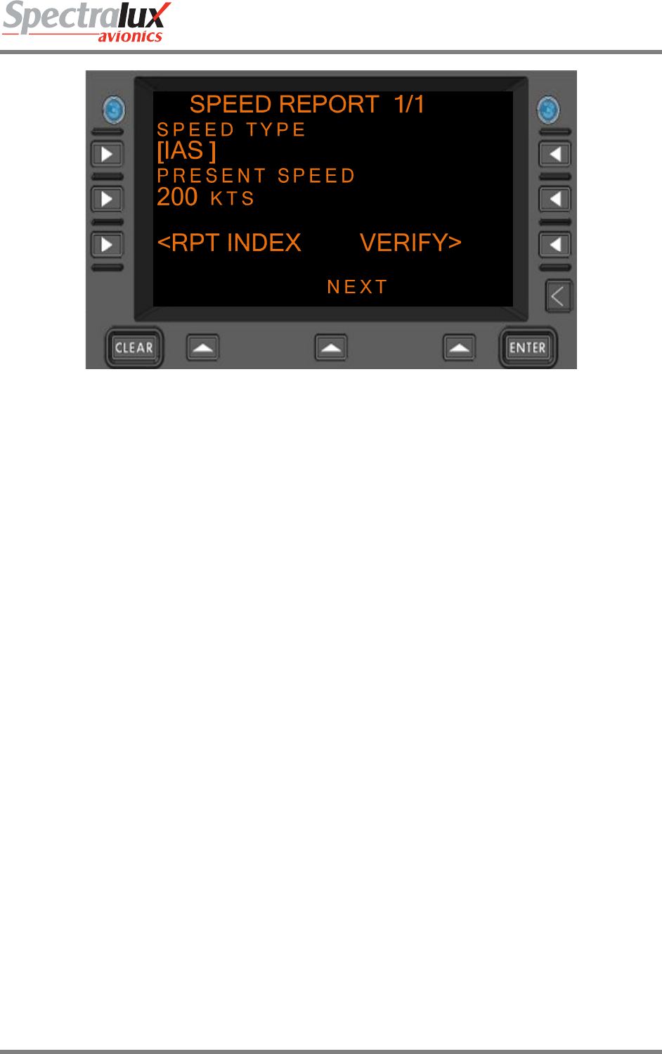
PRESENT SPEED English Format: NNN where “N” is a numerical
entry in the range of 0-400.
Metric Format: NNN where “N” is a numerical
entry in the range of 0-800.
An example of the Speed Report Menu with the ‘SPEED TYPE’ and ‘PRESENT SPEED’ fields filled in
and the ‘VERIFY’ prompt is shown in Figure 7.1.17-2
Dlink+CPDLC Users Guide
Document Number: UG-14114 Rev. - Page 156 of 201
Figure 7.1.17-2 SPEED REPORT Menu, Verify Prompt Displayed
Dlink+CPDLC Users Guide
Document Number: UG-14114 Rev. - Page 157 of 201
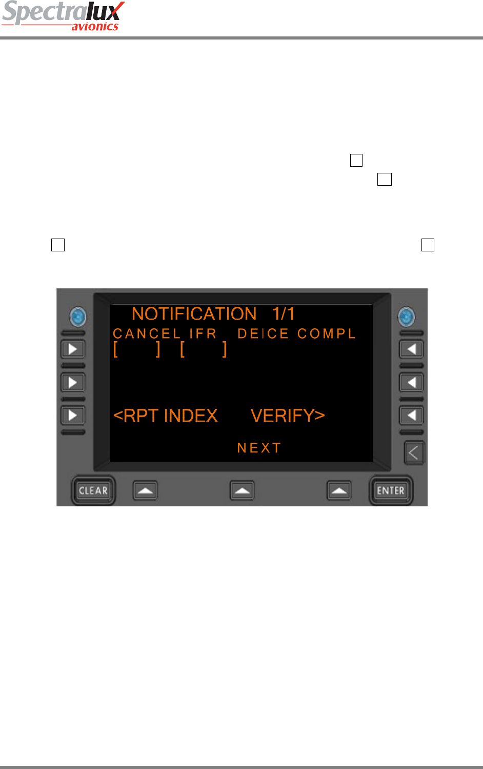
7.1.18 CPDLC – Notification Menu
The Notification Menu is only available when in DO 280B ATN Operational mode (see Section7.1.1).The
Notification Menu provides a means by which the operator may notify ATC that the IFR (Instrument Flight
Rules) Flight Plan has been cancelled. In addition, it also permits a second notification to indicate de-icing
is complete.
When configured for RTCA DO 280B Mode the following Notification Reports are valid:
• Cancelling IFR (CANCEL IFR field must be selected by pressing the L1 line select key)
• De-Icing Complete (DEICE COMPL field must be selected by pressing the R1 line select key)
An example of the blank Notification Menu (no entries made) is shown in Figure 7.1.18-1
PAGE NAVIGATION:
A. ► L2 Line Select Key from the CPDLC INDEX Menu (See section 7.1.1) then ► L3 Line
Select Key from the CPDLC INDEX Menu (See section 7.1.13)
Figure 7.1.18-1 NOTIFICATION Menu, DO 280B
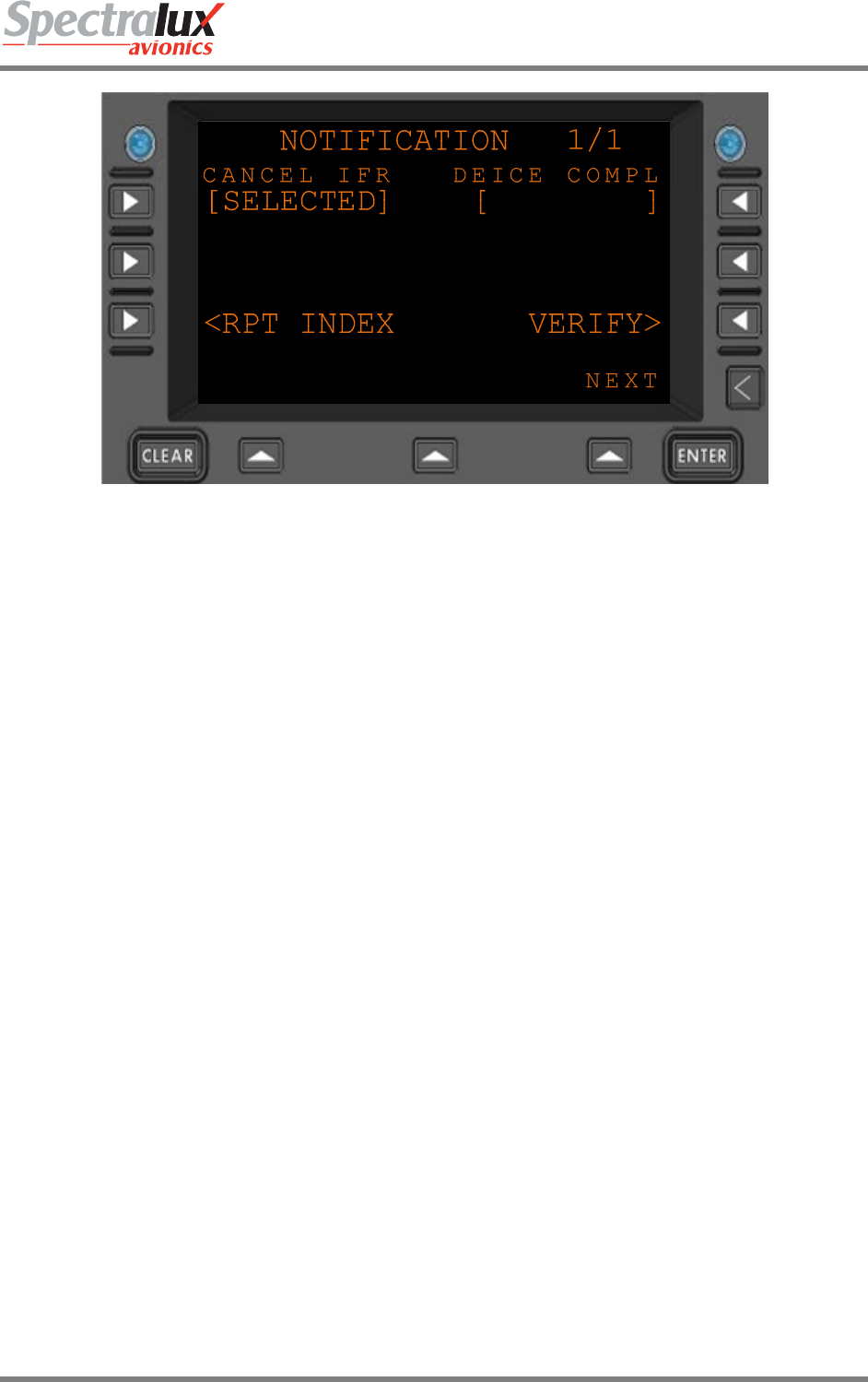
An example of the Notification Menu with the ‘CANCEL IFR’ field filled in and the ‘VERIFY’ prompt is
shown in Figure 7.1.18-2
Dlink+CPDLC Users Guide
Document Number: UG-14114 Rev. - Page 158 of 201
Figure 7.1.18-2 NOTIFICATION Menu, Verify Prompt Displayed
Dlink+CPDLC Users Guide
Document Number: UG-14114 Rev. - Page 159 of 201
7.2 CPDLC Operational Scenario
7.2.1 CM Logon
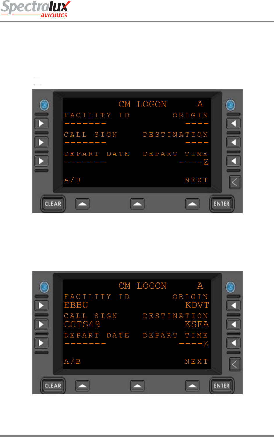
Say the operator is on the ground and wishes to perform a CM logon. First, the operator will have to
navigate to the ‘CM LOGON’ menu press the ‘CPDLC’ menu key and then select ‘CM LOGON’ by
pressing the L3 menu key. See Figure 7.2.1-1
Figure 7.2.1-1 CM LOGON Menu
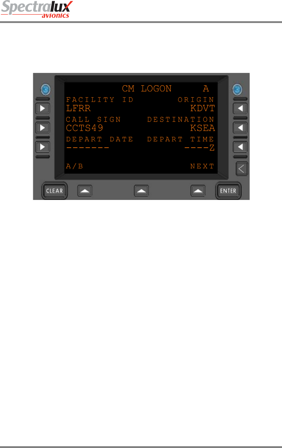
The operator then enters a Facility ID, Call Sign, Origin, and Destination on the A-Page in order to have
access to the ‘LOGON’ prompt found on the B-Page. A Depart Date and Time is not required to get the
‘LOGON’ prompt. However, if a Date is entered a Time must be entered (and vice versa) in order for the
LOGON prompt to appear. The menu with all required fields filled in is in Figure 7.2.1-2
Figure 7.2.1-2 CM LOGON Menu
Dlink+CPDLC Users Guide
Document Number: UG-14114 Rev. - Page 160 of 201
Here is what the B-Page of the CM LOGON Menu will look like after entering required information for a
CM Logon:
Figure 7.2.1-3 CM LOGON Menu
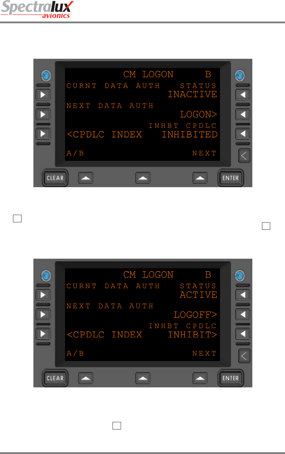
The R2 Line Select Key would then be pressed from the B-Page to select the ‘LOGON’ prompt and
perform a CM Logon. When successfully logged on the ‘LOGON’ Prompt located to the left of the R2 Line
Select Key on the B-Page will change to the ‘LOGOFF’ Prompt, the status will be set to ‘ACTIVE’, and
‘INHIBITED’ will change to ‘INHIBIT’ as seen in Figure 7.2.1-4
Figure 7.2.1-4 CM LOGON Menu
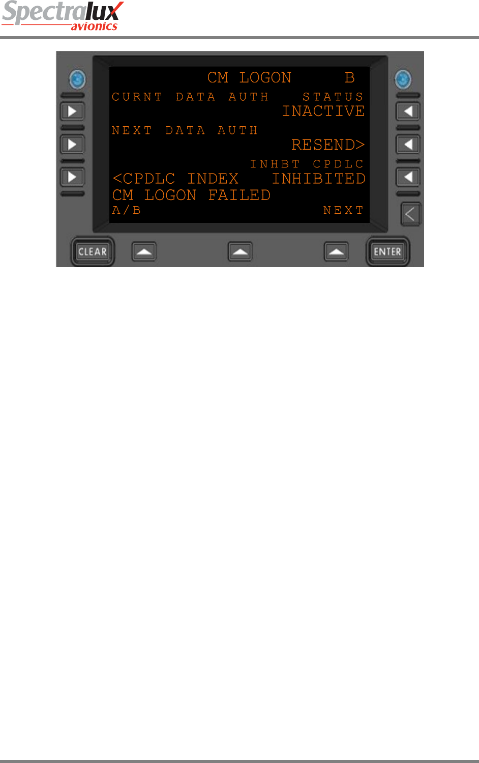
If the CM logon was not successful the ‘CM LOGON FAILED’ scratchpad message would be displayed
and the prompt that corresponds with the R2 Line Select Key would change to ‘RESEND’ as seen in
Figure 7.2.1-5
Dlink+CPDLC Users Guide
Document Number: UG-14114 Rev. - Page 161 of 201
Figure 7.2.1-5 CM LOGON Menu
Dlink+CPDLC Users Guide
Document Number: UG-14114 Rev. - Page 162 of 201
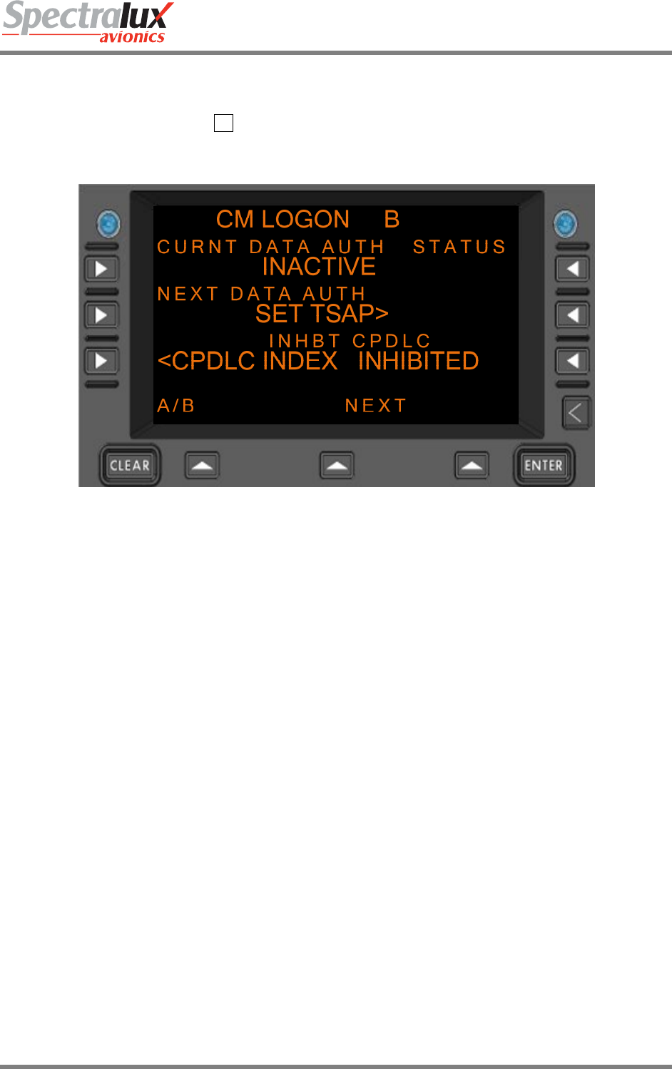
7.2.1.1 Manual Entry of TSAP Address
If the FACILITY ID that is entered on the CM Logon Menu does not exist within the TSAP database, the
prompt that corresponds with the R2 Line Select Key on the B-Page or the CM Logon Menu will change
to ‘SET TSAP’ in order for the operator to manually enter a TSAP address.
Figure 7.2.1-6 CM LOGON Menu
Selection of the ‘SET TSAP’ Prompt will cause the ‘ENTER TSAP’ Menu to be displayed. Once a valid
TSAP is entered the operator can save the TSAP entry and return to the CM Logon Menu by pressing the
Line Select Key that corresponds with the ‘SAVE TSAP’ Prompt.
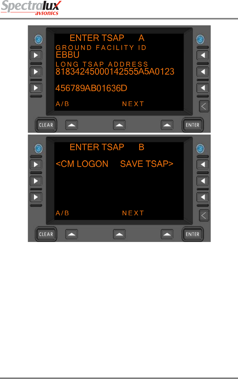
Dlink+CPDLC Users Guide
Document Number: UG-14114 Rev. - Page 163 of 201
Figure 7.2.1-7 ENTER TSAP Menu
Dlink+CPDLC Users Guide
Document Number: UG-14114 Rev. - Page 164 of 201
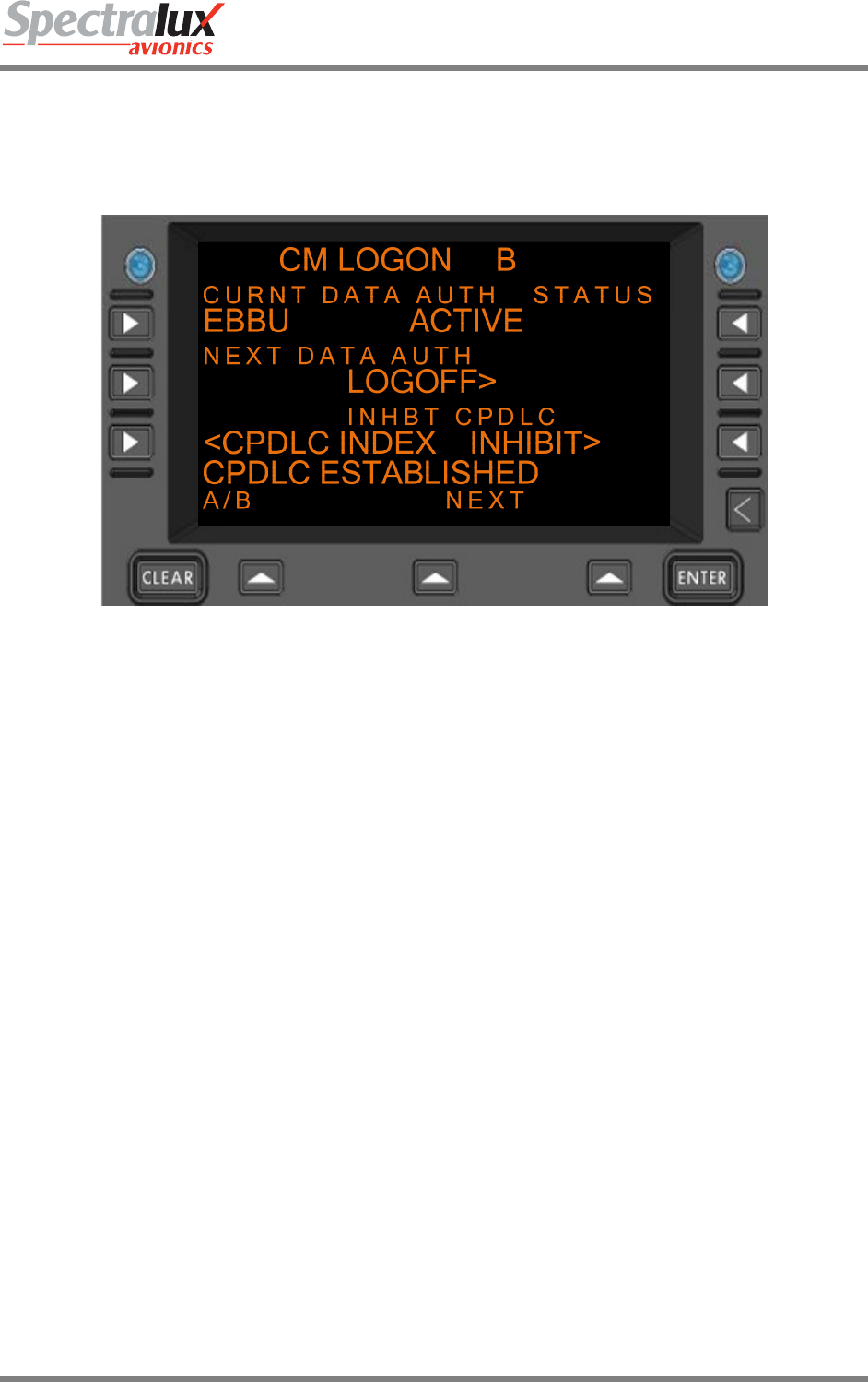
7.2.2 CPDLC Start from the Ground
Now assume the operator is at 20000 feet and a CPDLC start request is received from the ground. When
the start request is received from the ground ‘CPDLC ESTABLISHED’ will be displayed in the scratch pad
and the ground station that has sent the start request will be displayed as the current data authority as
shown in Figure 7.2.2-1
Figure 7.2.2-1 CM LOGON Menu
Dlink+CPDLC Users Guide
Document Number: UG-14114 Rev. - Page 165 of 201
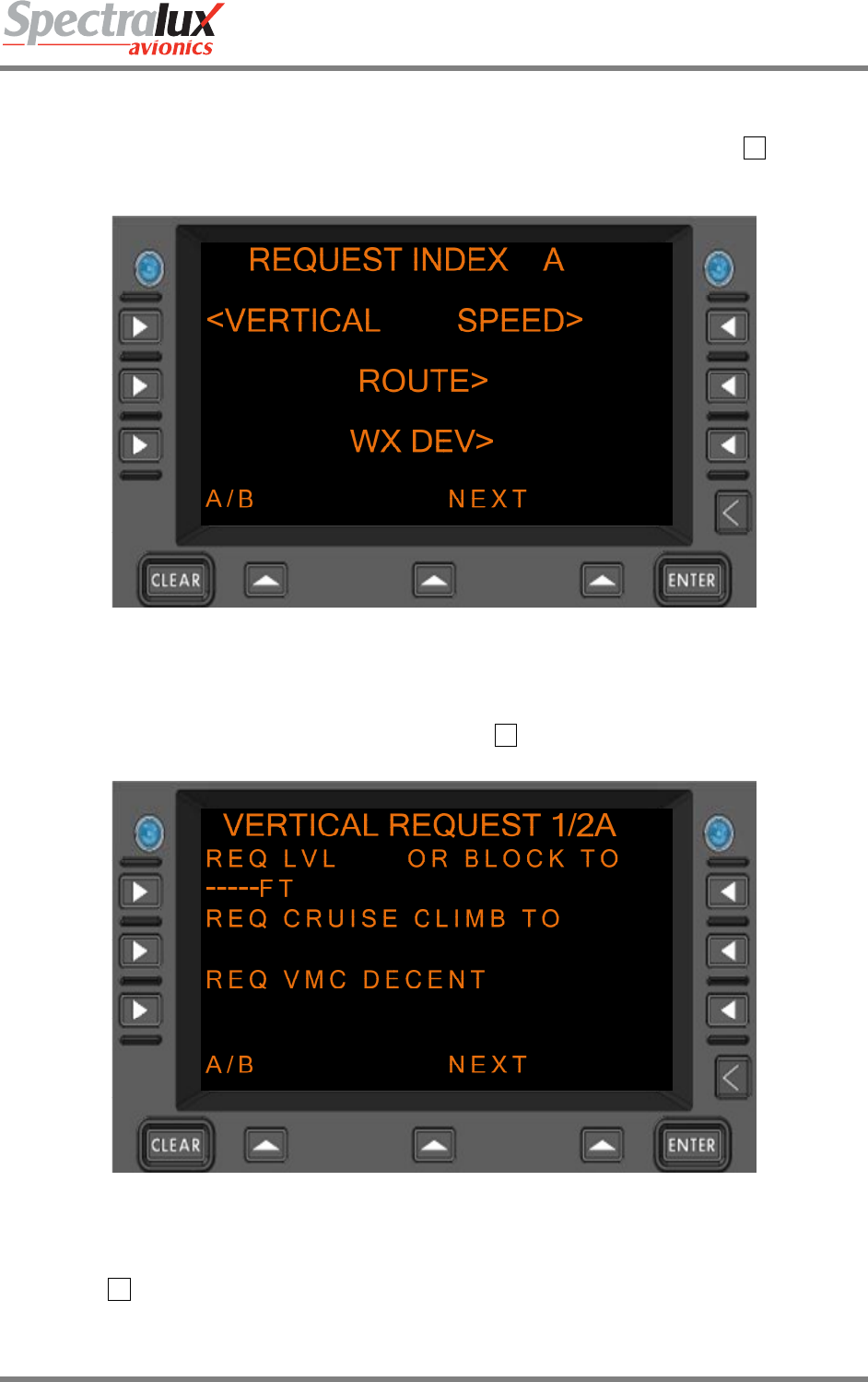
7.2.3 Vertical/Route Mod Message Exchange with ATC
Now assume that the operator wishes to request a vertical change to 25000 feet. The ‘CPDLC’ Function
Key would be pressed then the operator would select the ‘REQUEST’ field by pressing the L1 Line Select
Key. This section is based on LINK 2000 Mode, if RTCA DO280B Mode is selected the page display may
differ slightly. That menu, in LINK 2000 Mode, can be found in Figure 7.2.3-1:
Figure 7.2.3-1 REQUEST INDEX Menu
Now the operator would select ‘VERTICAL’ by pressing the L1 Line Select Key. The Vertical Request
menu is shown in Figure 7.2.3-2:
Figure 7.2.3-2 VERTICAL REQUEST Menu
25000 would then be entered into the scratch pad and up-selected to the ‘REQ LVL’ Line Field by
pressing the L1 Line Select Key. The VERTICAL REQUEST Menu is shown in Figure 7.2.3-3:
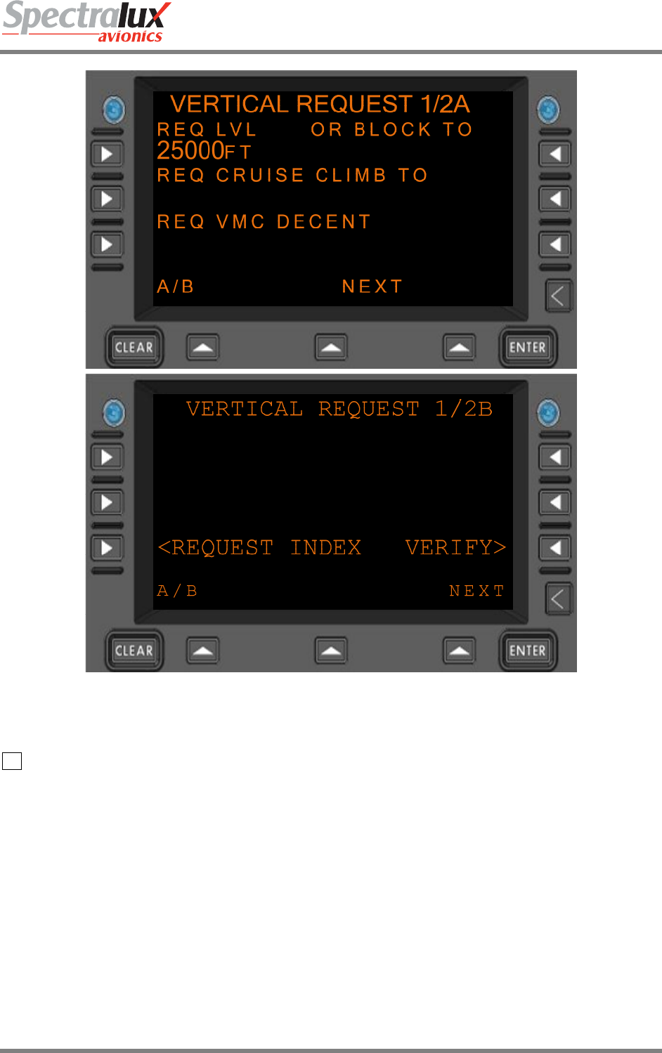
Dlink+CPDLC Users Guide
Document Number: UG-14114 Rev. - Page 166 of 201
Figure 7.2.3-3 VERTICAL REQUEST Menu
On the 1B-Page of the Vertical Request Menu the operator selects the ‘VERIFY’ Prompt by pressing the
R3 Line Select Key. This will bring the operator to the Verify Request Menu shown in Figure 7.2.3-4:
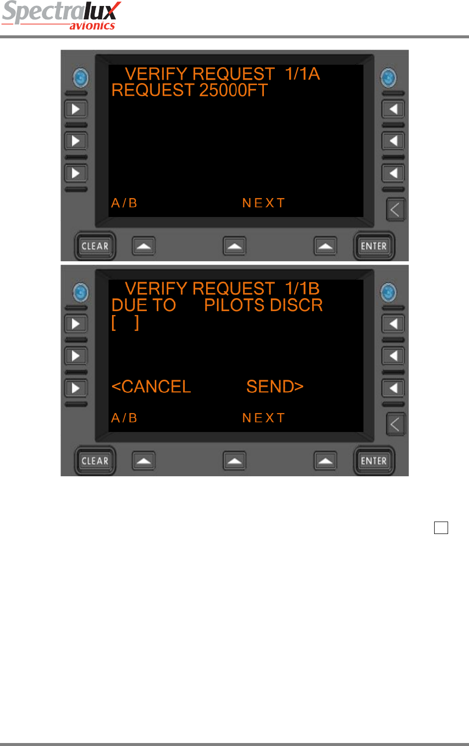
Dlink+CPDLC Users Guide
Document Number: UG-14114 Rev. - Page 167 of 201
Figure 7.2.3-4 VERIFY REQUEST Menu
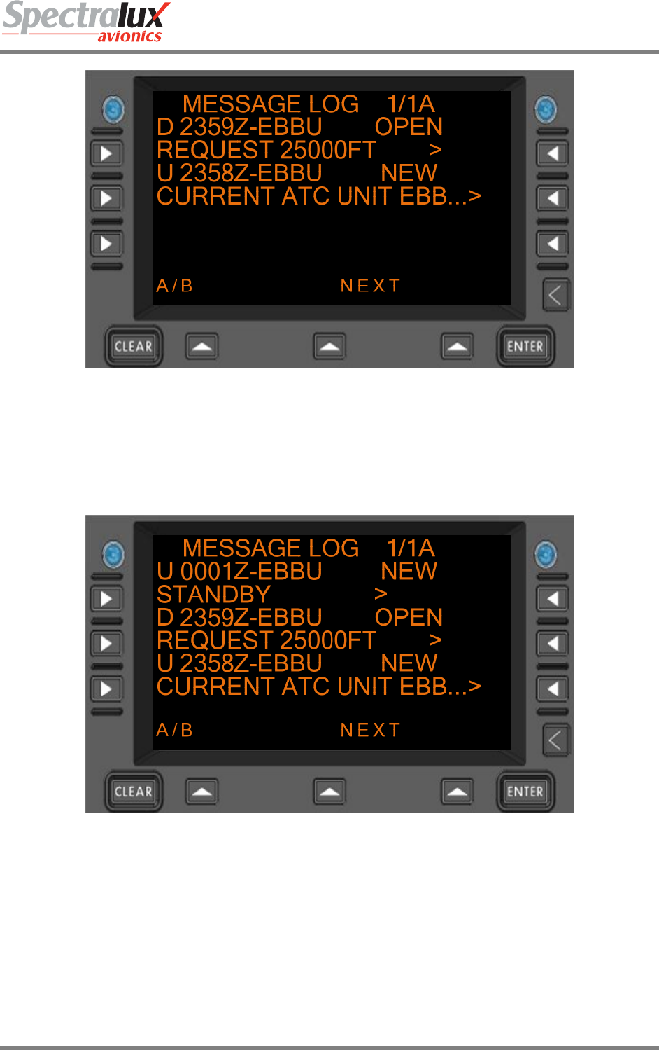
On the B-Page of the Verify Request Menu the ‘SEND’ prompt would be selected by pressing the R3
Line Select Key. Then a downlink in the CPDLC message log titled ‘REQUEST 25000FT’ will be
viewable in the Message Log as shown in Figure 7.2.3-5:
Dlink+CPDLC Users Guide
Document Number: UG-14114 Rev. - Page 168 of 201
Figure 7.2.3-5 MESSAGE LOG Menu
The ground could then send a standby to request that the operator wait for further instruction. The
standby is a viewable message in the CPDLC Message Log. An example of the standby in the Message
Log is found in Figure 7.2.3-6:
Figure 7.2.3-6 MESSAGE LOG Menu
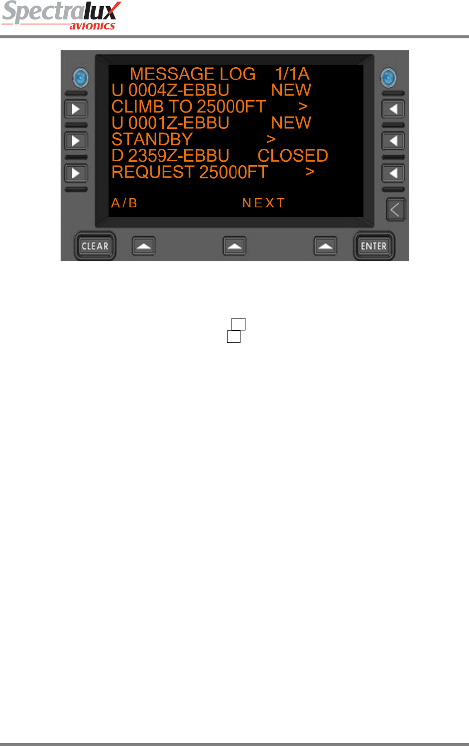
If the ground then sent the operator a request to go to 25000 feet the message would be displayed in the
CPDLC message log as shown in Figure 7.2.3-7. The operator can open and respond to this message.
Dlink+CPDLC Users Guide
Document Number: UG-14114 Rev. - Page 169 of 201
Figure 7.2.3-7 MESSAGE LOG Menu
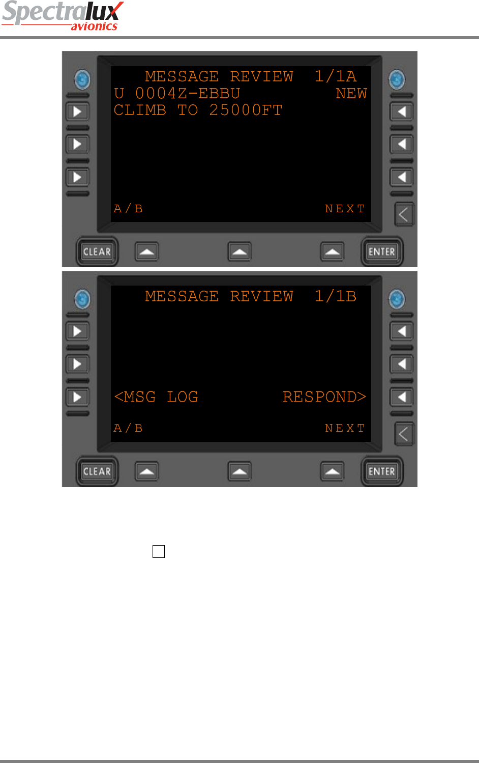
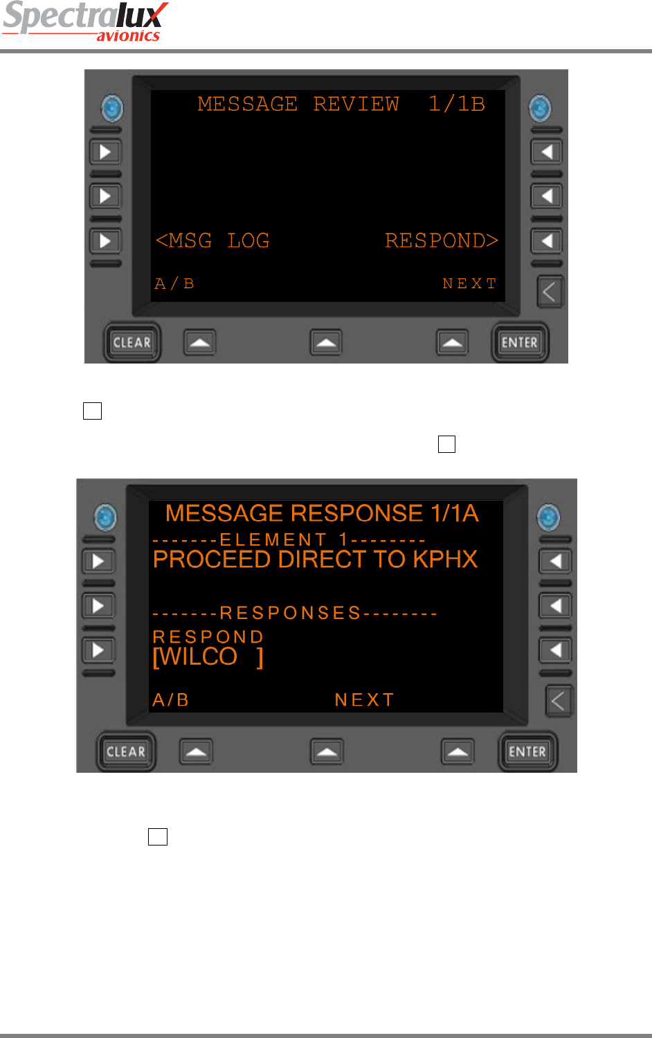
To respond to and accept the Climb To Request the operator would select the message in the Message
Log by pressing the corresponding Line Select Key, R1 in the above example, then select respond from
the B-Page of the message review by pressing the R3 Line Select Key while on the B-Page. See Figure
7.2.3-8:
Dlink+CPDLC Users Guide
Document Number: UG-14114 Rev. - Page 170 of 201
Figure 7.2.3-8 MESSAGE REVIEW Menu
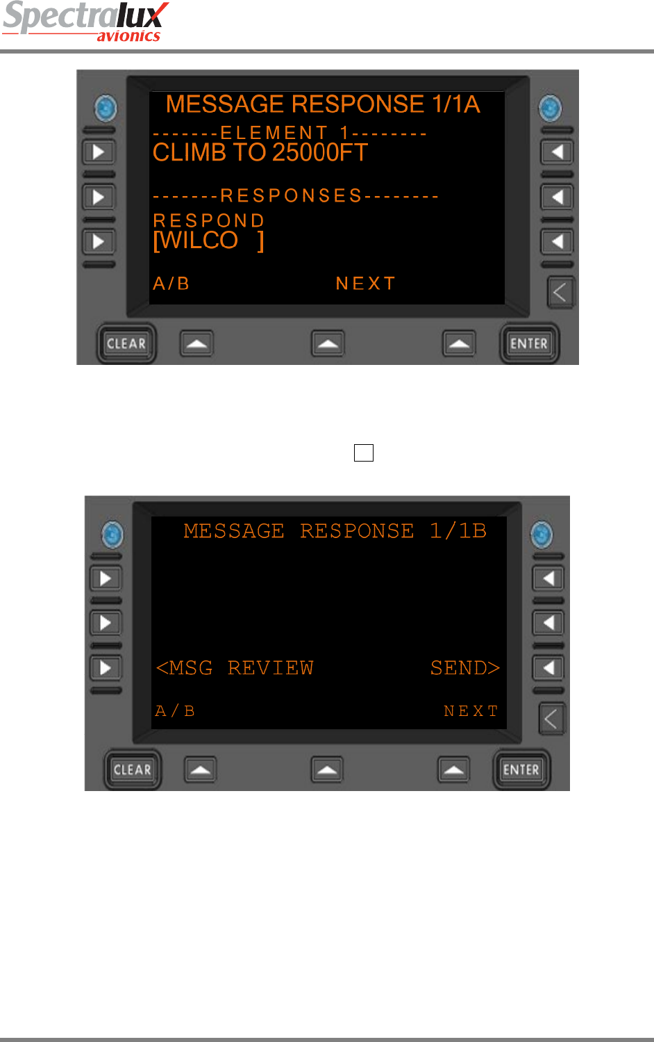
This brings the operator to the Message Response Menu. If the operator selects WILCO in the
‘RESPOND’ field by pressing the L2 Line Select Key and sends the response the Climb To Request
would be accepted. Figure 7.2.3-9 shows the MESSAGE RESPONSE Menu after selecting WILCO for a
response type.
Dlink+CPDLC Users Guide
Document Number: UG-14114 Rev. - Page 171 of 201
Figure 7.2.3-9 MESSAGE RESPONSE Menu
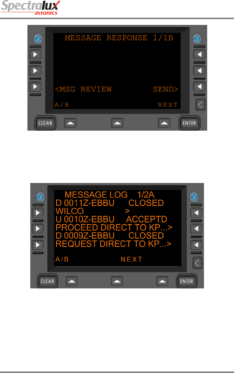
After setting the response type to WILCO the operator would navigate to the B-Page of the Message
Response and select the ‘SEND’ Prompt by pressing the R3 Line Select Key as seen in Figure 7.2.3-10
Figure 7.2.3-10 MESSAGE RESPONSE Menu
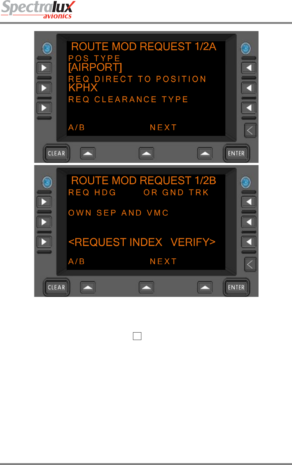
In the case that the operator wanted to request a route modification, the operator would navigate to the
Route Mod Request Menu by first pressing the ‘CPDLC’ Line Select Key, then selecting the ‘REQUEST’
field by pressing the L1 Line Select Key from the CPDLC Menu, and then selecting ‘ROUTE’ by pressing
the R2 Line Select Key. Then the operator must select a Position Type and a Request Direct to Position.
To select a Position Type the L1 Line Select Key is pressed, in the below example ‘AIRPORT’ is set for
the Position Type. Next a Request Direct to Position would be filled in by making an entry in the scratch
pad and then pressing the L2 Line Select Key to up-select the entry to that field. Figure 7.2.3-11 is an
example of this screen with the ‘POS TYPE’ and ‘REQ DIRECT TO POSITION’ fields filled in. This
information is needed in order to get a ‘VERIFY’ Prompt on the B-Page of the Route Mod Request page.
Dlink+CPDLC Users Guide
Document Number: UG-14114 Rev. - Page 172 of 201
Figure 7.2.3-11 ROUTE MOD REQUEST Menu
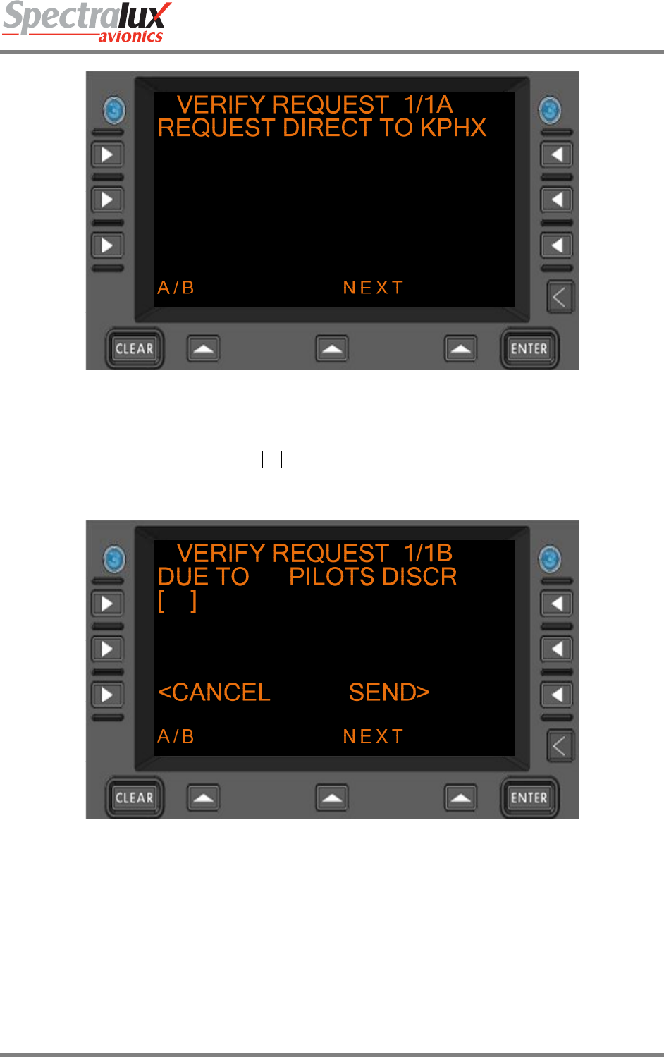
After entering this information the operator would navigate to the B-Page of the Route Mod Request page
and select the ‘VERIFY’ prompt by pressing the R3 Line Select Key. This will take you to the Verify
Request Menu. The Verify Request Menu is shown in Figure 7.2.3-12:
Dlink+CPDLC Users Guide
Document Number: UG-14114 Rev. - Page 173 of 201
Figure 7.2.3-12 VERIFY REQUEST Menu
If the operator navigates to the B-Page of the Verify Request Menu a ‘SEND’ prompt will be present. To
send the verified Route Mod Request the R3 Line Select Key would be pressed. Figure 7.2.3-13 shows
an example of the B-Page of the Verify Request with the ‘SEND’ Prompt:
Figure 7.2.3-13 VERIFY REQUEST Menu
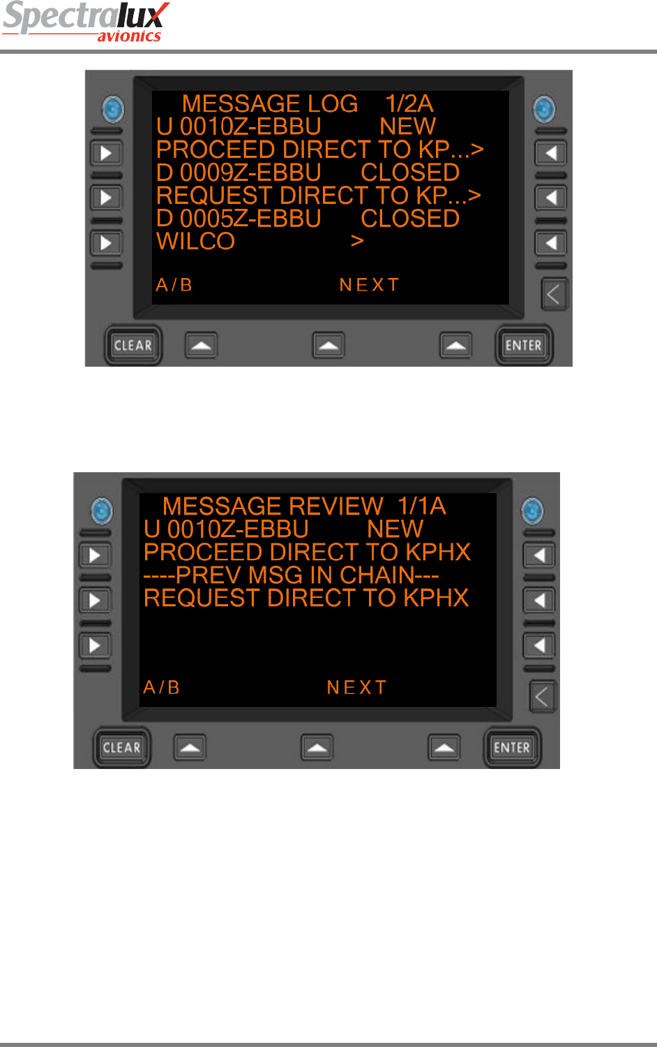
Now if the ground accepts the Route Mod Request, they will send up a Route Mod containing the same
information as the Request the operator sent in the downlink to the ground station. In the Message Log
this this would look like the example in Figure 7.2.3-14:
Dlink+CPDLC Users Guide
Document Number: UG-14114 Rev. - Page 174 of 201
Figure 7.2.3-14 MESSAGE LOG Menu
To accept the Route Mod sent up from the ground station the operator must select the uplink message
from the CPDLC Message Log which will bring the operator to the Message Review Menu:
Figure 7.2.3-15 MESSAGE REVIEW Menu
Navigating to the B-Page of the Lateral Offset will give the operator access to the ‘RESPOND’ Prompt.
The B-Page would look like the example in Figure 7.2.3-16:
Dlink+CPDLC Users Guide
Document Number: UG-14114 Rev. - Page 175 of 201
Figure 7.2.3-16 MESSAGE REVIEW Menu
Pressing the R3 Line Select Key from the B-Page of the Message Review Menu to select the ‘RESPOND’
prompt will bring the operator to the ‘Message Response Menu. On the ‘Message Response Menu, in
the ‘RESPOND’ field the operator would select WILCO by pressing the L3 Line Select Key once. Figure
7.2.3-17 shows an example of this page:
Figure 7.2.3-17 MESSAGE RESPONSE Menu
Then the operator would navigate to the B-Page of the Message Response Menu and select the ‘SEND’
Prompt by pressing the R3 Line Select Key shown in Figure 7.2.3-18:
Dlink+CPDLC Users Guide
Document Number: UG-14114 Rev. - Page 176 of 201
Figure 7.2.3-18 MESSAGE RESPONSE Menu
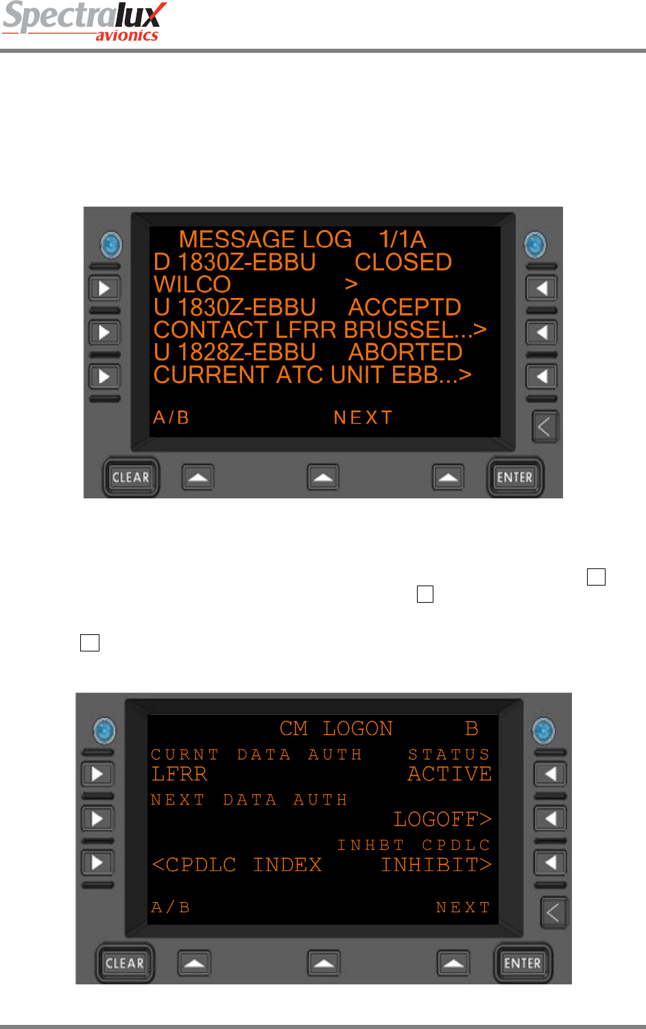
Sending the WILCO in response to the Route Mod accepts the ground stations Route Mod. This is
viewable in the message log shown in Figure 7.2.3-19 (notice the Route Mod now has an accepted
status):
Figure 7.2.3-19 MESSAGE LOG Menu

Dlink+CPDLC Users Guide
Document Number: UG-14114 Rev. - Page 177 of 201
7.2.4 Next Data Center Established
To establish a Next Data Authority the ground will first send an uplink that contains the facility ID for the
Next Data Authority. When the ground has sent this uplink the facility ID will be viewable on the ‘CM
LOGON’ menu in the ‘NEXT DATA AUTH’ field. This is in Figure 7.2.4-1 with a ‘NEXT DATA AUTH’ of
LFRR:
Figure 7.2.4-1 CM LOGON Menu
Dlink+CPDLC Users Guide
Document Number: UG-14114 Rev. - Page 178 of 201
7.2.5 Change of Current Data Center
In order for the Next Data Authority ( LFRR in the example ) to become the Current Data Authority it must
first send a Start Request, the Current Data Authority (EBBU in the example) must then send an End
Request containing the facility designation of the Next Data Authority. Then the operator would be able to
view and respond to a contact request in the CPDLC message log from the Next Data Authority. If the
operator choose to respond to this request with a WILCO the Next Data Authority would become the
Current Data Authority. Figure 7.2.5-1 shows the contact request after the operator has responded with
a WILCO to accept the Contact Request from the new station:
Figure 7.2.5-1 MESSAGE LOG Menu
The steps that should be taken to do this will be to navigate to the CPDLC message log, select the
contact request from the Next Data Authority by pressing the Line Select Key that corresponds to the
message, navigate to the B-Page of the Message Review Menu, select respond by pressing the R3 Line
Select Key on the B-Page of the message review, then pressing the L2 Line Select Key on the Response
Menu to select WILCO for a response type if the operator wishes to accept the Contact Request. Then
the operator would send the response by navigating to the B-Page of the Message Response Menu and
pressing the R3 Line Select Key to select the ‘SEND’ Prompt. Figure 7.2.5-2 shows what the B-Page of
the CM Logon Menu will look like after these steps are done and the Current Data Authority has changed
to LFRR.
Figure 7.2.5-2 CM LOGON Menu
Dlink+CPDLC Users Guide
Document Number: UG-14114 Rev. - Page 179 of 201
7.2.6 Contact Request
If the active facility (EBBU) sent a contact request to a second available facility (LFRR) and that facility
responded with a CM Logon Response the second facility would become the active facility and this would
be viewable from the CM Logon Menu. This is shown in Figure 7.2.6-1
Figure 7.2.6-1 CM LOGON Menu

Dlink+CPDLC Users Guide
Document Number: UG-14114 Rev. - Page 180 of 201
7.3 Supported ATN CPDLC Messages
7.3.1 Uplink Messages Supported by Dlink+ w/CPDLC
The list below defines those uplink messages supported by Dlink+ w/CPDLC when in RTCA DO280B
ATN Operational Mode. When in LINK 2000 ATN Operational Mode, supported uplink messages are
limited to those messages that are shaded in yellow. (See Section7.1.1 for information on how the ATN
Operational Mode can be changed.)
Uplink Message
Element
Message Element Format Message Intent
0 UNABLE UNABLE - Indicates that ATC cannot comply with the
request.
1 STANDBY STANDBY - Indicates that ATC has received the
message and will respond.
2 REQUEST DEFERRED REQUEST DEFERRED - Indicates that ATC has
received the request but it has been deferred until later.
3 ROGER ROGER - Indicates that ATC has received and
understood the message.
4 AFFIRM AFFIRM - Yes.
5 NEGATIVE NEGATIVE - No.
6 EXPECT 25000FT EXPECT [level] - Notification that a level change
instruction should be expected.
7 EXPECT CLIMB AT 1232
EXPECT CLIMB AT [time] - Notification that an
instruction should be expected for the aircraft to
commence climb at the specified time.
8
EXPECT CLIMB AT KXX
EXPECT CLIMB AT [position] - Notification that an
instruction should be expected for the aircraft to
commence climb at the specified position.
9 EXPECT DESCENT AT 1232
EXPECT DESCENT AT [time] - Notification that an
instruction should be expected for the aircraft to
commence descent at the specified time.
10 EXPECT DESCENT AT XXZ
EXPECT DESCENT AT [position] - Notification that an
instruction should be expected for the aircraft to
commence descent at the specified position.
11 EXPECT CRUISE CLIMB AT 1232
EXPECT CRUISE CLIMB AT [time] - Notification that an
instruction should be expected for the aircraft to
commence cruise climb at the specified time.
12 EXPECT CRUISE CLIMB AT XYZ
EXPECT CRUISE CLIMB AT [position] -Notification that
an instruction should be expected for the aircraft to
commence cruise climb at the specified position.
13
AT 1232 EXPECT CLIMB TO 25000FT
AT [time] EXPECT CLIMB TO [level] - Notification that an
instruction should be expected for the aircraft to
commence climb at the specified time to the specified
level.
14
AT XYZ EXPECT CLIMB TO 25000FT
AT [position] EXPECT CLIMB TO [level] - Notification that
an instruction should be expected for the aircraft to
commence climb at the specified position to the specified
level.
15
AT 1232 EXPECT DESCENT TO 25000FT
AT [time] EXPECT DESCENT TO [level] -Notification that
an instruction should be expected for the aircraft to
commence descent at the specified time to the specified
level.

Dlink+CPDLC Users Guide
Document Number: UG-14114 Rev. - Page 181 of 201
Uplink Message
Element
Message Element Format Message Intent
16
AT XYZ EXPECT DESCENT TO 25000FT
AT [position] EXPECT DESCENT TO [level] -Notification
that an instruction should be expected for the aircraft to
commence descent at the specified position to the
specified level.
17
AT 1232 EXPECT CRUISE CLIMB TO 25000FT
AT [time] EXPECT CRUISE CLIMB TO [level] -
Notification that an instruction should be expected for the
aircraft to commence cruise climb at the specified time to
the specified level.
18
AT XYZ EXPECT CRUISE CLIMBE TO 25000FT
AT [position] EXPECT CRUISE CLIMBE TO [level] -
Notification that an instruction should be expected for the
aircraft to commence cruise climb at the specified
position to the specified level.
19 MAINTAIN 25000FT
MAINTAIN [level] - Instruction to maintain the
specified level.
20 CLIMB TO 25000FT
CLIMB TO [level] - Instruction that a climb to a specified
level is to commence and once reached the specified
level is to be maintained.
21
AT 1232 CLIMB TO 25000FT
AT [time] CLIMB TO [level] - Instruction that at the
specified time a climb to the specified level is to
commence and once reached the specified level is to be
maintained.
22
AT XYZ CLIMB TO 25000FT
AT [position] CLIMB TO [level] - Instruction that at the
specified position a climb to the specified level is to
commence and once reached the specified level is to be
maintained.
23 DESCEND TO 25000FT
DESCEND TO [level] - Instruction that a descent to a
specified level is to commence and once reached the
specified level is to be maintained.
24
AT 1232 DESCEND TO 25000FT
AT [time] DESCEND TO [level] - Instruction that at a
specified time a descent to a specified level is to
commence and once reached the specified level is to be
maintained.
25
AT XYZ DESCEND TO 25000FT
AT [position] DESCEND TO [level] - Instruction that at the
specified position a descent to the specified level is to
commence and once reached the specified level is to be
maintained.
26 CLIMB TO REACH [level] BY 1232
CLIMB TO REACH [level] BY [time] - Instruction that a
climb is to commence at a rate such that the specified
level is reached at or before the specified time.
27 CLIMB TO REACH 25000FT BY XYZ
CLIMB TO REACH [level] BY [postion] -Instruction that a
climb is to commence at a rate such that the specified
level is reached at or before the specified position.
28 DESCEND TO REACH 25000FT BY 1232
DESCEND TO REACH [level] BY [time] -Instruction that
a descent is to commence at a rate such that the
specified level is reached at or before the specified time.
29
DESCEND TO REACH 25000FT BY XYZ
DESCEND TO REACH [level] BY [position] -Instruction
that a descent is to commence at a rate such that the
specified level is reached at or before the specified
position.
30 MAINTAIN BLOCK 25000FT TO 25000FT
MAINTAIN BLOCK [level] TO [level] - Instruction that a
level within the defined vertical range specified is to be
maintained.
31 CLIMB TO AND MAINTAIN BLOCK 25000FT TO
30000FT CLIMB TO AND MAINTAIN BLOCK [level] TO [level] -
Instruction that a climb to a level within the vertical range

Dlink+CPDLC Users Guide
Document Number: UG-14114 Rev. - Page 182 of 201
Uplink Message
Element
Message Element Format Message Intent
defined is to commence.
32 DESCEND TO AND MAINTAIN BLOCK 25000FT TO
20000FT
DESCEND TO AND MAINTAIN BLOCK [level] TO [level]
- Instruction that a descent to a level within the vertical
range defined is to commence.
34 CRUISE CLIMB TO 25000FT
CRUISE CLIMB TO [level] - Instruction that a cruise climb
is to commence and continue until the specified level is
reached.
35 CRUISE CLIMB TO 25000FT CRUISE CLIMB ABOVE [level] - Instruction that a cruise
climb can commence once above the specified level.
36 EXPEDITE CLIMB TO 25000FT
EXPEDITE CLIMB TO [level] - Instruction that the climb
to the specified level should be made at the aircraft’s best
rate.
37 EXPEDITE DESCENT TO 25000FT
EXPEDITE DESCENT TO [level] - Instruction that the
descent to the specified level should be made at the
aircraft’s best rate.
38 IMMEDIATELY CLIMB TO 25000FT IMMEDIATELY CLIMB TO [level] – Urgent instruction to
immediately climb to the specified level.
39 IMMEDIATELY DESCEND TO 25000FT IMMEDIATELY DESCEND TO [level] – Urgent instruction
to immediately descend to the specified level.
42
EXPECT TO CROSS XYZ AT 25000FT
EXPECT TO CROSS [position] AT [level] -Notification
that a level change instruction should be expected which
will require the specified position to be crossed at the
specified level.
43
EXPECT TO CROSS XYZ AT OR ABOVE 25000FT
EXPECT TO CROSS [position] AT OR ABOVE [level] -
Notification that a level change instruction should be
expected which will require the specified position to be
crossed at or above the specified level.
44
EXPECT TO CROSS XYZ AT OR BELOW 25000FT
EXPECT TO CROSS [position] AT OR BELOW [level] -
Notification that a level change instruction should be
expected which will require the specified position to be
crossed at or below the specified level.
45
EXPECT TO CROSS XYZ AT AND MAINTAIN 25000FT
EXPECT TO CROSS [position] AT AND MAINTAIN
[level] - Notification that a level change instruction should
be expected which will require the specified position to be
crossed at the specified level which is to be maintained
subsequently.
46
CROSS XYZ AT 25000FT
CROSS [position] AT [level] - Instruction that the
specified position is to be crossed at the specified level.
This may require the aircraft to modify its climb or
descent profile.
47 CROSS XYZ AT OR ABOVE 25000FT
CROSS [position] AT OR ABOVE [level] -Instruction that
the specified position is to be crossed at or above the
specified level.
48 CROSS XYZ AT OR ABOVE 25000FT
CROSS [position] AT OR BELOW [level] - Instruction that
the specified position is to be crossed at or below the
specified level.
49
CROSS XYZ AT AND MAINTAIN 25000FT
CROSS [position] AT AND MAINTAIN [level] -Instruction
that the specified position is to be crossed at the
specified level and that level is to be maintained when
reached.
50 CROSS XYZ BETWEEN 20000FT AND 25000FT
CROSS [position] BETWEEN [level] AND [level] -
Instruction that the specified position is to be crossed at a
level between the specified levels.

Dlink+CPDLC Users Guide
Document Number: UG-14114 Rev. - Page 183 of 201
Uplink Message
Element
Message Element Format Message Intent
51 CROSS XYZ AT 1232 CROSS [position] AT [time] - Instruction that the specified
position is to be crossed at the specified time.
52 CROSS XYZ AT OR BEFORE 1232
CROSS [position] AT OR BEFORE [time] -Instruction that
the specified position is to be crossed at or before the
specified time.
53 CROSS XYZ AT OR AFTER 1232
CROSS [position] AT OR AFTER [time] -Instruction that
the specified position is to be crossed at or after the
specified time.
54 CROSS XYZ BETWEEN 1230 AND 1250
CROSS [position] BETWEEN [time] AND [time] -
Instruction that the specified position is to be crossed at
or after the specified time.
55
CROSS XYZ AT 200KTS
CROSS [position] AT [speed] - Instruction that the
specified position is to be crossed at the specified speed
and the specified speed is to be maintained until further
advised.
56
CROSS XYZ AT OR LESS THAN 200KTS
CROSS [position] AT OR LESS THAN [speed] -
Instruction that the specified position is to be crossed at a
speed equal to or less than the specified speed and the
specified speed or less is to be maintained until further
advised.
57
CROSS XYZ AT OR GREATER THAN 200KTS
CROSS [position] AT OR GREATER THAN [speed] -
Instruction that the specified position is to be crossed at a
speed equal to or greater than the specified speed and
the specified speed or greater is to be maintained until
further advised.
58 CROSS XYZ AT 1232 AT 25000FT
CROSS [position] AT [time] AT [level] - Instruction that
the specified position is to be crossed at the specified
time and the specified level.
59 CROSS XYZ AT OR BEFORE 1232 AT 25000FT
CROSS [position] AT OR BEFORE [time] AT [level] -
Instruction that the specified position is to be crossed at
or before the specified time and at the specified level.
60 CROSS XYZ AT OR AFTER 1232 AT 25000FT
CROSS [position] AT OR AFTER [time] AT [level] -
Instruction that the specified position is to be crossed at
or after the specified time and at the specified level.
61
CROSS XYZ AT AND MAINTAIN 25000FT AT 200KTS
CROSS [position] AT AND MAINTAIN [level] AT [speed] -
Instruction that the specified position is to be crossed at
the specified level and speed, and the level and speed
are to be maintained.
62
AT 1232 CROSS XYZ AT AND MAINTAIN 25000FT
AT [time] CROSS [position] AT AND MAINTAIN [level] -
Instruction that at the specified time the specified position
is to be crossed at the specified level and the level is to
be maintained.
63 AT 1232 CROSS XYZ AT AND MAINTAIN 25000FT AT
200KTS
AT [time] CROSS [position] AT AND MAINTAIN [level]
AT [speed] - Instruction that at the specified time the
specified position is to be crossed at the specified level
and speed, and the level and speed are to be maintained.
64
OFFSET 200KM LEFT OF ROUTE
OFFSET [specifiedDistance] [direction] OF ROUTE -
Instruction to fly a parallel track to the cleared route at a
displacement of the specified distance in the specified
direction.
65
AT XYZ OFFSET 200KM LEFT OF ROUTE
AT [position] OFFSET [specifiedDistance] [direction] OF
ROUTE - Instruction to fly a parallel track to the cleared
route at a displacement of the specified distance in the
specified direction and commencing at the specified
position.

Dlink+CPDLC Users Guide
Document Number: UG-14114 Rev. - Page 184 of 201
Uplink Message
Element
Message Element Format Message Intent
66
AT 1232 OFFSET 200KM LEFT OF ROUTE
AT [time] OFFSET [specifiedDistance] [direction] OF
ROUTE - Instruction to fly a parallel track to the cleared
route at a displacement of the specified distance in the
specified direction and commencing at the specified time.
67 PROCEED BACK ON ROUTE PROCEED BACK ON ROUTE - Instruction that the
cleared flight route is to be rejoined.
68 REJOIN ROUTE BY XYZ
REJOIN ROUTE BY [position] - Instruction that the
cleared flight route is to be rejoined at or before the
specified position.
69 REJOIN ROUTE BY 1232
REJOIN ROUTE BY [time] - Instruction that the cleared
flight route is to be rejoined at or before the specified
time.
70 EXPECT BACK ON ROUTE BY XYZ
EXPECT BACK ON ROUTE BY [position] -Notification
that a clearance may be issued to enable the aircraft to
rejoin the cleared route at or before the specified position.
71 EXPECT BACK ON ROUTE BY 1232
EXPECT BACK ON ROUTE BY [time] -Notification that a
clearance may be issued to enable the aircraft to rejoin
the cleared route at or before the specified time.
72
RESUME OWN NAVIGATION
RESUME OWN NAVIGATION - Instruction to resume
own navigation following a period of tracking or heading
clearances. May be used in conjunction with an
instruction on how or where to rejoin the cleared route.
73 EBBU CLEARED TO: AAAAA
[DepartureClearance] - Notification to the aircraft of the
instructions to be followed from departure until the
specified clearance limit.
74 PROCEED DIRECT TO XYZ PROCEED DIRECT TO [position] - Instruction to proceed
directly from its present position to the specified position.
75 WHEN ABLE PROCEED DIRECT TO XYZ
WHEN ABLE PROCEED DIRECT TO [position] -
Instruction to proceed, when able, directly to the specified
position.
76 AT 1232 PROCEED DIRECT TO XYZ
AT [time] PROCEED DIRECT TO [position] - Instruction
to proceed, at the specified time, directly to the specified
position.
77 AT ABA PROCEED DIRECT TO XYZ
AT [position] PROCEED DIRECT TO [position] -
Instruction to proceed, at the specified position, directly to
the next specified position.
78 AT 25000FT PROCEED DIRECT TO XYZ
AT [level] PROCEED DIRECT TO [position] -Instruction
to proceed, upon reaching the specified level, directly to
the specified position.
79
CLEARED TO XYZ VIA
-options selected in the route clearance will be viewable
when the message is opened from the CPDLC message
log
CLEARED TO [position] VIA [routeClearance] -Instruction
to proceed to the specified position via the specified
route.
80
CLEARED
-options selected in the route clearance will be viewable
when the message is opened from the CPDLC message
log
CLEARED [routeClearance] - Instruction to proceed via
the specified route.
81 CLEARED ARRIVAL, XYZ.ABC CLEARED [procedureName] - Instruction to proceed in
accordance with the specified procedure.
82 CLEARED TO DEVIATE UP TO 200KM LEFT OF
ROUTE
CLEARED TO DEVIATE UP TO [specifiedDistance]
[direction] OF ROUTE - Approval to deviate up to the
specified distance from the cleared route in the specified

Dlink+CPDLC Users Guide
Document Number: UG-14114 Rev. - Page 185 of 201
Uplink Message
Element
Message Element Format Message Intent
direction.
83
AT XYZ CLEARED
-options selected in the route clearance will be viewable
when the message is opened from the CPDLC message
log
AT [position] CLEARED [routeClearance] -Instruction to
proceed from the specified position via the specified
route.
84 AT XYZ CLEARED ARRIVAL, XYZ.ABC
AT [position] CLEARED [procedureName] -Instruction to
proceed from the specified position via the specified
procedure.
85
EXPECT
-options selected in the route clearance will be viewable
when the message is opened from the CPDLC message
log
EXPECT [routeClearance] - Notification that a clearance
to fly on the specified route may be issued.
86
AT XYZ EXPECT
-options selected in the route clearance will be viewable
when the message is opened from the CPDLC message
log
AT [position] EXPECT [routeClearance] - Notification that
a clearance to fly on the specified route from the
specified position may be issued.
87 EXPECT DIRECT TO XYZ
EXPECT DIRECT TO [position] – Notification that a
clearance to fly directly to the specified position may be
issued.
88 AT ABA EXPECT DIRECT TO XYZ
AT [position] EXPECT DIRECT TO [position] -Notification
that a clearance to fly directly from the first specified
position to the next specified position may be issue
89 AT 1232 EXPECT DIRECT TO XYZ
AT [time] EXPECT DIRECT TO [position] -Notification
that a clearance to fly directly to the specified position
commencing at the specified time may be issued.
90
AT 25000FT EXPECT DIRECT TO XYZ
AT [level] EXPECT DIRECT TO [position] -Notification
that a clearance to fly directly to the specified position
commencing when the specified level is reached may be
issued.
91 HOLD AT XYZ MAINTAIN 25000FT INBOUND TRACK
010T LEFT TURNS 100KM
HOLD AT [position] MAINTAIN [level] INBOUND TRACK
[degrees][direction] TURNS [legtype] -Instruction to enter
a holding pattern with the specified characteristics at the
specified position and level.
92 HOLD AT XYZ AS PUBLISHED MAINTAIN 25000FT
HOLD AT [position] AS PUBLISHED MAINTAIN [level] -
Instruction to enter a holding pattern with the published
characteristics at the specified position and level.
93 EXPECT FURTHER CLEARANCE AT 1232
EXPECT FURTHER CLEARANCE AT [time] -Notification
that an onwards clearance may be issued at the specified
time.
94 TURN LEFT HEADING 010T TURN [direction] HEADING [degrees] - Instruction to turn
left or right as specified on to the specified heading.
95 TURN LEFT GROUND TRACK 010T TURN [direction] GROUND TRACK [degrees] -Instruction
to turn left or right as specified on to the specified track.
96 CONTINUE PRESENT HEADING CONTINUE PRESENT HEADING - Instruction to turn left
or right as specified on to the specified track.
97 AT XYZ FLY HEADING 010T AT [position] FLY HEADING [degrees] -Instruction to
continue to fly on the current heading.
98 IMMEDIATELY TURN LEFT HEADING 010T
IMMEDIATELY TURN [direction] HEADING [degrees] -
Instruction to turn immediately left or right as specified on
to the specified heading.
99 EXPECT ARRIVAL, XYZ.ABC EXPECT [procedureName] - Notification that a clearance
may be issued for the aircraft to fly the specified

Dlink+CPDLC Users Guide
Document Number: UG-14114 Rev. - Page 186 of 201
Uplink Message
Element
Message Element Format Message Intent
procedure.
100 AT 1232 EXPECT 200KTS
AT [time] EXPECT [speed] - Notification that a speed
instruction may be issued to be effective at the specified
time.
101 AT XYZ EXPECT 200KTS
AT [position] EXPECT [speed] - Notification that a speed
instruction may be issued to be effective at the specified
position.
102 AT 25000FT EXPECT 200KTS
AT [level] EXPECT [speed] - Notification that a speed
instruction may be issued to be effective at the specified
level.
103 AT 1232 EXPECT 200KTS TO 100KTS
AT [time] EXPECT [speed] TO [speed] -Notification that a
speed range instruction may be issued to be effective at
the specified time.
104 AT XYZ EXPECT 200KTS TO 100KTS
AT [position] EXPECT [speed] TO [speed] -Notification
that a speed range instruction may be issued to be
effective at the specified position.
105 AT 25000FT EXPECT 200KTS TO 100KTS
AT [level] EXPECT [speed] TO [speed] -Notification that
a speed range instruction may be issued to be effective
at the specified level.
106 MAINTAIN 200KTS MAINTAIN [speed] - Instruction that the specified speed
is to be maintained.
107 MAINTAIN PRESENT SPEED MAINTAIN PRESENT SPEED - Instruction that the
present speed is to be maintained.
108 MAINTAIN 200KTS OR GREATER MAINTAIN [speed] OR GREATER - Instruction that the
specified speed or a greater speed is to be maintained.
109 MAINTAIN 200KTS OR LESS MAINTAIN [speed] OR LESS - Instruction that the
specified speed or a lesser speed is to be maintained.
110 MAINTAIN 200KTS TO 100KTS MAINTAIN [speed] TO [speed] - Instruction that a speed
within the specified range is to be maintained.
111 INCREASE SPEED TO 200KTS
INCREASE SPEED TO [speed] - Instruction that the
present speed is to be increased to the specified speed
and maintained until further advised.
112
INCREASE SPEED TO 200KTS OR GREATER
INCREASE SPEED TO [speed] OR GREATER -
Instruction that the present speed is to be increased to
the specified speed or greater, and maintained at or
above the specified speed until further advised.
113 REDUCE SPEED TO 200KTS
REDUCE SPEED TO [speed] - Instruction that the
present speed is to be reduced to the specified speed
and maintained until further advised.
114
REDUCE SPEED TO 200KTS OR LESS
REDUCE SPEED TO [speed] OR LESS -Instruction that
the present speed is to be reduced to the specified speed
or less and maintained at or below the specified speed
until further advised.
115 DO NOT EXCEED 200KTS DO NOT EXCEED [speed] - Instruction that the specified
speed is not to be exceeded.
116 RESUME NORMAL SPEED
RESUME NORMAL SPEED - Notification that the aircraft
need no longer comply with the previously issued speed
restriction.
117 CONTACT LFRR CENTER 136.975MHZ
CONTACT [unitname] [frequency] - Instruction that the
ATS unit with the specified ATS unit name is to be
contacted on the specified frequency.
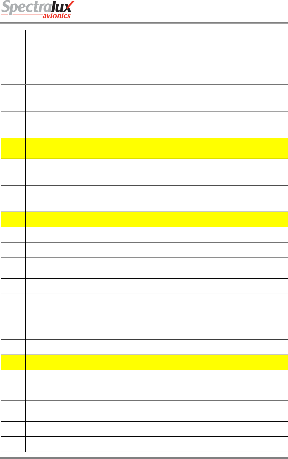
Dlink+CPDLC Users Guide
Document Number: UG-14114 Rev. - Page 187 of 201
Uplink Message
Element
Message Element Format Message Intent
118
AT XYZ CONTACT EBBU CENTER 136.975MHZ
AT [position] CONTACT [unitname] [frequency] -
Instruction that at the specified position the ATS unit with
the specified ATS unit name is to be contacted on the
specified frequency.
119
AT 1232 CONTACT EBBU CENTER 136.975MHZ
AT [time] CONTACT [unitname] [frequency] -Instruction
that at the specified time the ATS unit with the specified
ATS unit name is to be contacted on the specified
frequency.
120 MONITOR EBBU CENTER 136.975MHZ
MONITOR [unitname] [frequency] – Instruction that the
ATS unit with the specified ATS unit name is to be
monitored on the specified frequency.
121
AT XYZ MONITOR EBBU CENTER 136.975MHZ
AT [position] MONITOR [unitname] [frequency] -
Instruction that at the specified position the ATS unit with
the specified ATS unit name is to be monitored on the
specified frequency.
122
AT 1232 MONITOR EBBU CENTER 136.975MHZ
AT [time] MONITOR [unitname] [frequency] -Instruction
that at the specified time the ATS unit with the specified
ATS unit name is to be monitored on the specified
frequency.
123 SQUAWK 0123 SQUAWK [code] - Instruction that the specified code
(SSR code) is to be selected.
124 STOP SQUAWK STOP SQUAWK - Instruction that the SSR transponder
responses are to be disabled.
125 SQUAWK MODE CHARLIE SQUAWK MODE CHARLIE - Instruction that the SSR
transponder responses should include level information.
126 SQUAWK MODE CHARLIE
STOP SQUAWK MODE CHARLIE - Instruction that the
SSR transponder responses should no longer include
level information.
127 Report Back On Route Report Back On Route - Instruction to report when the
aircraft is back on the cleared route.
128 Report Leaving 25000FT Report Leaving [LEVEL] - Instruction to report when the
aircraft has left the specified level.
129 Report Leaving 25000FT Report Maintaining [LEVEL] - Instruction to report when
the aircraft is in level flight at the specified level.
130 Report Passing XYZ Report Passing [POSITION] - Instruction to report when
the aircraft has passed the specified position.
132 Report Position Report Position - Instruction to report the present
position.
133 Report Present Level Report Present Level - Instruction to report the present
level.
135 Confirm Assigned Level Confirm Assigned Level - Instruction to confirm and
acknowledge the currently assigned level.
136 Confirm Assigned Level Confirm Assigned Speed - Instruction to confirm and
acknowledge the currently assigned speed.
138 Confirm Time Over reported Waypoint Confirm Time Over reported Waypoint -Instruction to
confirm the previously reported time over the last
reported waypoint.
139 Confirm Reported Waypoint Confirm Reported Waypoint - Instruction to confirm the
identity of the previously reported waypoint.
140 Confirm Next Waypoint Confirm Next Waypoint - Instruction to confirm the
identity of the next waypoint.

Dlink+CPDLC Users Guide
Document Number: UG-14114 Rev. - Page 188 of 201
Uplink Message
Element
Message Element Format Message Intent
141 Confirm Next Waypoint ETA Confirm Next Waypoint ETA - Instruction to confirm the
previously reported estimated time at the next waypoint.
142 Confirm Next Waypoint ETA Confirm Ensuing Waypoint - Instruction to confirm the
identity of the next but one waypoint.
144 Confirm Squawk Confirm Squawk - Instruction to report the selected (SSR)
code.
145 Report Heading Report Heading - Instruction to report the present
heading.
146 Report Ground Track Report Ground Track - Instruction to report the present
ground track.
147 Request Position Report Request Position Report - Instruction to make a position
report.
148 When Can You Accept 25000FT When Can You Accept [LEVEL] - Request for the earliest
time at which the specified level can be accepted.
151 When Can You Accept 200KTS When Can You Accept [SPEED] - Instruction to report the
earliest time when the specified speed can be accepted.
152 When Can You Accept 200KM LEFT Offset
When Can You Accept [SPECIFIED DISTANCE]
[DIRECTION] Offset - Instruction to report the earliest
time when the specified offset track can be accepted.
153 ALTIMETER 23.00HG ALTIMETER [altimeter] - ATS advisory that the altimeter
setting should be the specified setting.
154 RADAR SERVICE TERMINATED RADAR SERVICE TERMINATED – ATS advisory that
the radar service is terminated.
155 RADAR CONTACT XYZ RADAR CONTACT [position] - ATS advisory that radar
contact has been established at the specified position.
156 RADAR CONTACT LOST RADAR CONTACT LOST - ATS advisory that radar
contact has been lost.
157 CHECK STUCK MICROPHONE 136.975MHZ
CHECK STUCK MICROPHONE [frequency] -Instruction
that a continuous transmission is detected on the
specified frequency. Check the microphone button.
158 CHECK STUCK MICROPHONE 136.975MHZ
ATIS [atiscode] - ATS advisory that the ATIS information
identified by the specified code is the current ATIS
information.
159 ERROR INSUFFICIENT RESOURCES
ERROR [errorInformation] - A system generated
message notifying that the ground system has detected
an error.
160
A UM160 WILL NOT SHOW UP IN THE CPDLC
MESSAGE LOG. WHEN ONE IS RECEIVED THE
‘NEXT DATA AUTH’ FIELD ON SCREEN B OF THE ‘CM
LOGON’ PAGE WILL CONTAIN A FACILITY ID OF THE
NEXT DATA AUTORITY.
NEXT DATA AUTHORITY [facility] – Notification to the
avionics that the specified data authority is the next data
authority. If no data authority is specified, this indicates
that any previously specified next data authority is no
longer valid.
161 END SERVICE
END SERVICE - Notification to the avionics that the data
link connection with the current data authority is being
terminated.
162 MESSAGE NOT SUPPORTED BY THIS ATS UNIT
MESSAGE NOT SUPPORTED BY THIS ATS UNIT -
Notification that the ground system does not support this
message.
163 LFRR [facilitydesignation] - Notification to the pilot of an ATSU
identifier.
164 WHEN READY WHEN READY - The associated instruction may be
complied with at any future time.

Dlink+CPDLC Users Guide
Document Number: UG-14114 Rev. - Page 189 of 201
Uplink Message
Element
Message Element Format Message Intent
165 THEN THEN - Used to link two messages, indicating the proper
order of execution of clearances/ instructions.
166 DUE TO CROSSING TRAFFIC DUE TO [traffictype]TRAFFIC - The associated
instruction is issued due to traffic considerations.
167 DUE TO AIRSPACE RESTRICTION DUE TO AIRSPACE RESTRICTION – The associated
instruction is issued due to airspace restrictions.
168 DISREGARD DISREGARD - The indicated communication should be
ignored.
169 Up to 256 alpha-numeric characters and symbols [freetext]
170 Up to 256 alpha-numeric characters and symbols [freetext]
171 CLIMB AT 20000FPM MINIMUM CLIMB AT [verticalRate] MINIMUM – Instruction to climb
at not less than the specified rate.
172 CLIMB AT 25000FPM MAXIMUM CLIMB AT [verticalRate] MAXIMUM - Instruction to climb
at not above the specified rate.
173 DESCEND AT 7000FPM MINIMUM DESCEND AT [verticalRate] MINIMUM -Instruction to
descend at not less than the specified rate.
174 DESCEND AT 15000FPM MAXIMUM DESCEND AT [verticalRate] MAXIMUM -Instruction to
descend at not above the specified rate.
175 Report Reaching 25000FT Report Reaching [LEVEL] - Instruction to report when the
aircraft has reached the specified level.
176
MAINTAIN OWN SEPARATION AND VMC
MAINTAIN OWN SEPARATION AND VMC -Notification
that the pilot is responsible for maintaining separation
from other traffic and is also responsible for maintaining
visual meteorological conditions.
177 AT PILOTS DISCRETION
AT PILOTS DISCRETION - Used in conjunction with a
clearance/instruction to indicate that the pilot may
execute when prepared to do so.
179 SQUAWK IDENT SQUAWK IDENT - Instruction that the ‘ident’ function on
the SSR transponder is to be actuated.
180 Report Reaching Block 20000FT to 25000FT
Report Reaching Block [LEVEL] to [LEVEL] -Instruction
to report when the aircraft is within the specified vertical
range.
181 Report Distance TO XYZ Report Distance [TO/FROM] [POSITION] -Instruction to
report the present distance to or from the specified
position.
182 Confirm ATIS Code Confirm ATIS Code - Instruction to report the
identification code of the last ATIS received.
183 Up to 256 alpha-numeric characters and symbols [freetext]
184 At Time 1232 Report Distance FROM XYZ
At Time [TIME] Report Distance [TO/FROM] [POSITION]
- Instruction to report at the specified time the distance to
or from the specified position.
185
AFTER PASSING XYZ CLIMB TO 25000FT
AFTER PASSING [position] CLIMB TO [level] -Instruction
that after passing the specified position a climb to the
specified level is to commence and once reached the
specified level is to be maintained.
186
AFTER PASSING XYZ DESCEND TO 20000FT
AFTER PASSING [position] DESCEND TO [level] -
Instruction that after passing the specified position a
descent to the specified level is to commence and once
reached the specified level is to be maintained.
187 Up to 256 alpha-numeric characters and symbols [freetext]
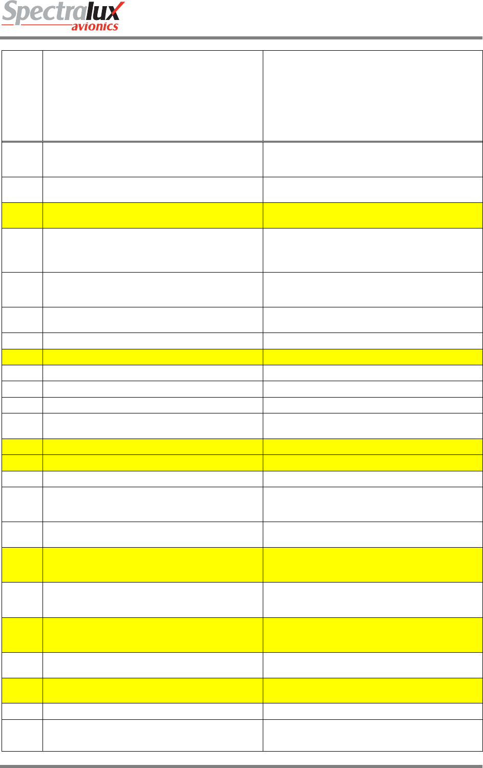
Dlink+CPDLC Users Guide
Document Number: UG-14114 Rev. - Page 190 of 201
Uplink Message
Element
Message Element Format Message Intent
188 AFTER PASSING XYZ MAINTAIN 200KTS
AFTER PASSING [position] MAINTAIN [speed] -
Instruction that after passing the specified position the
specified speed is to be maintained.
189 ADJUST SPEED TO 200KTS ADJUST SPEED TO [speed] - Instruction that the present
speed is to be changed to the specified speed.
190 FLY HEADING 150T FLY HEADING [degrees] - Instruction to fly on the
specifiedheading.
191
ALL ATS TERMINATED
ALL ATS TERMINATED - ATS advisory that the aircraft
is entering airspace in which no air traffic services are
provided and all existing air traffic services are
terminated.
192 REACH 25000FT BY 1232
REACH [level] BY [time] - Instruction that a change of
level is to continue, but at a rate such that the specified
level is reached at or before the specified time.
193 IDENTIFICATION LOST IDENTIFICATION LOST - Notification that radar
identification has been lost.
195 Up to 256 alpha-numeric characters and symbols [freetext]
196 Up to 256 alpha-numeric characters and symbols [freetext]
197 Up to 256 alpha-numeric characters and symbols [freetext]
198 Up to 256 alpha-numeric characters and symbols [freetext]
199 Up to 256 alpha-numeric characters and symbols [freetext]
200 Report Reaching Report Reaching - Instruction used in conjunction with a
level clearance to report reaching the level assigned.
203 Up to 256 alpha-numeric characters and symbols [freetext]
205 Up to 256 alpha-numeric characters and symbols [freetext]
208 Up to 256 alpha-numeric characters and symbols [freetext]
209 REACH 25000FT BY XYZ REACH [level] BY [position] - Instruction that a change of
level is to continue, but at a rate such that the specified
level is reached at or before the specified position.
210 IDENTIFIED XYZ IDENTIFIED [position] - ATS advisory that the aircraft has
been identified on radar at the specified position.
211 REQUEST FORWARDED REQUEST FORWARDED - Indicates that the ATC has
received the request and has passed it to the next control
authority.
212 EBBU ATIS A CURRENT [facilitydesignation] ATIS [atiscode] CURRENT -ATS
advisory that the specified ATIS information at the
specified airport is current.
213 EBBU ALTIMETER 800.0HPA [facilitydesignation] ALTIMETER [altimeter] – ATS
advisory that the specified altimeter setting relates to the
specified facility.
214 RVR RUNWAY 20L 200FT RVR RUNWAY [runway] [rvr] - ATS advisory that
indicates the RVR value for the specified runway.
215 TURN LEFT 200 TURN [direction][degrees] - Instruction to turn a specified
number of degrees left or right.
216 Request Flight Plan Request Flight Plan - Instruction to file a flight plan.
217 Report Arrival
Report Arrival - Instruction to report that the
aircraft has landed.

Dlink+CPDLC Users Guide
Document Number: UG-14114 Rev. - Page 191 of 201
Uplink Message
Element
Message Element Format Message Intent
218 REQUEST ALREADY RECEIVED
REQUEST ALREADY RECEIVED - Indicates to the pilot
that the request has already been received on the
ground.
219 STOP CLIMB AT 25000FT STOP CLIMB AT [level] - Instruction to stop the climb
below the previously assigned level.
220 STOP DESCENT AT 25000FT STOP DESCENT AT [level] - Instruction to stop the
descent above the previously assigned level.
221 STOP TURN HEADING 150T
STOP TURN HEADING [degrees] - Instruction to stop
turn at the specified heading prior to reaching the
previously assigned heading.
222 NO SPEED RESTRICTION NO SPEED RESTRICTION - Notification that the aircraft
may keep its preferred speed without restriction.
223 REDUCE TO MINIMUM APPROACH SPEED
REDUCE TO MINIMUM APPROACH SPEED -Instruction
to reduce present speed to the minimum safe approach
speed.
224 NO DELAY EXPECTED NO DELAY EXPECTED - ATS advisory that no delay is
expected.
225 DELAY NOT DETERMINED DELAY NOT DETERMINED - ATS advisory that the
expected delay has not been determined.
226 EXPECTED APPROACH TIME 1245
EXPECTED APPROACH TIME [time] – ATS advisory
that the aircraft may expect to be cleared to commence
its approach procedure at the specified time.
227
LOGICAL ACKNOWLEDGMENT
LOGICAL ACKNOWLEDGMENT - Confirmation to the
aircraft system that the ground system has received the
message to which the logical acknowledgment refers and
found it acceptable for display to the responsible person.
228 Report ETA XYZ Report ETA [POSITION] - Instruction to report the
estimated time of arrival at the specified position.
229 Report Alternate Aerodrome Report Alternate Aerodrome - Instruction to report the
preferred alternate aerodrome for landing.
230 IMMEDIATELY IMMEDIATELY - The associated instruction is to be
complied with immediately.
231 State Preferred Level State Preferred Level - Instruction to indicate the pilot’s
preferred level.
232 State Top Of Descent
State Top Of Descent - Instruction to indicate the pilot’s
preferred time and/or position to commence descent to
the aerodrome of intended arrival.
233
USE OF LOGICAL ACKNOWLEDGMENT PROHIBITED
USE OF LOGICAL ACKNOWLEDGMENT PROHIBITED
- Notification to the pilot that messages sent requiring a
logical acknowledgment will not be accepted by this
ground system.
234 FLIGHT PLAN NOT HELD FLIGHT PLAN NOT HELD - Notification that the ground
system does not have a flight plan for that aircraft.
236 LEAVE CONTROLLED AIRSPACE LEAVE CONTROLLED AIRSPACE – Instruction to leave
controlled airspace.
237
REQUEST AGAIN WITH NEXT UNIT
REQUEST AGAIN WITH NEXT UNIT – Indicates that the
request cannot be responded to by the current unit, and
that it should be requested from the next unit

Dlink+CPDLC Users Guide
Document Number: UG-14114 Rev. - Page 192 of 201
7.3.2 Downlink Messages Supported by Dlink+ w/CPDLC
The table below defines those downlink messages supported by Dlink+ w/CPDLC when in RTCA
DO280B ATN Operational Mode. When in LINK 2000 ATN Operational Mode, supported downlink
messages are limited to those messages that are shaded in yellow. (See Section7.1.1) for information on
how the ATN Operational Mode can be changed.)
Downlink
Message Element
Message Element Format Message Intent
0 WILCO WILCO - The instruction is understood and will be
complied with.
1 UNABLE UNABLE - The instruction cannot be complied with.
2 STANDBY STANDBY - Wait for a reply.
3 ROGER ROGER - Message received and understood.
4 AFFIRM AFFIRM - Yes.
5 NEGATIVE NEGATIVE - No.
6 REQUEST 25000FT REQUEST [level] - Request to fly at the specified level.
7 REQUEST BLOCK 20000FT TO 25000FT REQUEST BLOCK [level] TO [level] - Request to fly at a
level within the specified vertical range.
8 REQUEST CRUISE CLIMB TO 25000FT REQUEST CRUISE CLIMB TO [level] – Request to
cruise climb to the specified level.
9 REQUEST CLIMB TO 25000FT REQUEST CLIMB TO [level] - Request to climb to the
specified level.
10 REQUEST DESCENT TO 20000FT REQUEST DESCENT TO [level] - Request to descend to
the specified level.
11 AT XYZ REQUEST CLIMB TO 25000FT
AT [position] REQUEST CLIMB TO [level] -Request that
at the specified position a climb to the specified level be
approved.
12 AT ABC REQUEST DESCENT TO 15000FT
AT [position] REQUEST DESCENT TO [level] -Request
that at the specified position a descent to the specified
level be approved.
13 AT 1254 REQUEST CLIMB TO 25000FT
AT [time] REQUEST CLIMB TO [level] – Request that at
the specified time a climb to the specified level be
approved.
14 AT 1032 REQUEST DESCENT TO 22000FT
AT [time] REQUEST DESCENT TO [level] -Request that
at the specified time a descent to the specified level be
approved.
15
REQUEST OFFSET 200KM LEFT OF ROUTE
REQUEST OFFSET [specifiedDistance] [direction] OF
ROUTE - Request that a parallel track, offset from the
cleared track by the specified distance in the specified
direction, be approved.
16
AT ABC REQUEST OFFSET 200KM LEFT OF ROUTE
AT [position] REQUEST OFFSET [specifiedDistance]
[direction] OF ROUTE -Request that a parallel track,
offset from the cleared track by the specified distance in
the specified direction, be approved from the specified
position.
17
AT 1221 REQUEST OFFSET 150KM RIGHT OF ROUTE
AT [time] REQUEST OFFSET [specifiedDistance]
[direction] OF ROUTE - Request that a parallel track,
offset from the cleared track by the specified distance in
the specified direction, be approved from the specified
time.

Dlink+CPDLC Users Guide
Document Number: UG-14114 Rev. - Page 193 of 201
Downlink
Message Element
Message Element Format Message Intent
18 REQUEST 200KTS REQUEST [speed] - Request to fly at the specified
speed.
19 REQUEST 150KTS TO 200KTS REQUEST [speed] TO [speed] - Request to fly within the
specified speed range.
20 REQUEST VOICE CONTACT REQUEST VOICE CONTACT - Request for voice
contact.
21 REQUEST VOICE CONTACT 136.975 REQUEST VOICE CONTACT [frequency] -Request for
voice contact on the specified frequency.
22 REQUEST DIRECT TO XYZ REQUEST DIRECT TO [position] - Request to track from
the present position direct to the specified position.
23 REQUEST ARRIVAL, XYZ.ABC REQUEST [procedureName] - Request for the specified
procedure clearance.
25 REQUEST ARRIVAL, XYZ.ABC CLEARANCE REQUEST [clearanceType] CLEARANCE -Request for a
clearance.
27 REQUEST WEATHER DEVIATION UP TO 150KM
RIGHT OF ROUTE
REQUEST WEATHER DEVIATION UP TO
[specifiedDistance] [direction] OF ROUTE - Request for a
weather deviation up to the specified distance off track in
the specified direction.
28 LEAVING 20000FT LEAVING [level] - Notification of leaving the specified
level.
29 CLIMBING TO 25000FT CLIMBING TO [level] - Notification of climbing to the
specified level.
30 DESCENDING TO 23000FT DESCENDING TO [level] - Notification of descending to
the specified level.
31 PASSING XYZ PASSING [position] - Notification of passing the specified
position.
32 PRESENT LEVEL 23000FT PRESENT LEVEL [level] - Notification of the present
level.
33 PRESENT POSITION XYZ PRESENT POSITION [position] - Notification of the
present position.
34 PRESENT SPEED 200KTS PRESENT SPEED [speed] - Notification of the present
speed.
35 PRESENT HEADING 150T PRESENT HEADING [degrees] - Notification of the
present heading in degrees.
36 PRESENT GROUND TRACK 165 PRESENT GROUND TRACK [degrees] -Notification of
the present ground track in degrees.
37 MAINTAINING 23000FT MAINTAINING [level] - Notification that the aircraft is
maintaining the specified level.
38 ASSIGNED LEVEL 23000FT ASSIGNED LEVEL [level] - Read-back of the assigned
level.
39 ASSIGNED SPEED 200KTS ASSIGNED SPEED [speed] - Read-back of the assigned
speed.
41 BACK ON ROUTE BACK ON ROUTE - The aircraft has regained the cleared
route.
42 NEXT WAYPOINT DAR NEXT WAYPOINT [position] - The next waypoint is the
specified position.
43 NEXT WAYPOINT ETA 1124 NEXT WAYPOINT ETA [time] - The ETA at the next
waypoint is as specified.
44 ENSUING WAYPOINT DAR ENSUING WAYPOINT [position] - The next but one

Dlink+CPDLC Users Guide
Document Number: UG-14114 Rev. - Page 194 of 201
Downlink
Message Element
Message Element Format Message Intent
waypoint is the specified position.
45 REPORTED WAYPOINT DAR REPORTED WAYPOINT [position] - Clarification of
previously reported waypoint passage.
46 REPORTED WAYPOINT 1124 REPORTED WAYPOINT [time] - Clarification of time over
previously reported waypoint.
47 SQUAWKING 2130 SQUAWKING [code] - The specified (SSR) code has
been selected.
48 POSITION REPORT XYZ POSITION REPORT [positionreport] - Position report.
49 WHEN CAN WE EXPECT 200KTS
WHEN CAN WE EXPECT [speed] - Request for the
earliest time at which a clearance to the specified speed
can be expected.
50 WHEN CAN WE EXPECT 150KTS TO 200KTS
WHEN CAN WE EXPECT [speed] TO [speed] -Request
for the earliest time at which a clearance to a speed
within the specified range can be expected.
51 WHEN CAN WE EXPECT BACK ON ROUTE
WHEN CAN WE EXPECT BACK ON ROUTE -Request
for the earliest time at which a clearance to regain the
planned route can be expected.
52 WHEN CAN WE EXPECT LOWER LEVEL
WHEN CAN WE EXPECT LOWER LEVEL -Request for
the earliest time at which a clearance to descend can be
expected.
53 WHEN CAN WE EXPECT HIGHER LEVEL
WHEN CAN WE EXPECT HIGHER LEVEL -Request for
the earliest time at which a clearance to climb can be
expected.
54 WHEN CAN WE EXPECT CRUISE CLIMB TO 25000FT
WHEN CAN WE EXPECT CRUISE CLIMB TO [level] -
Request for the earliest time at which a clearance to
cruise climb to the specified level can be expected.
62 ERROR INSUFFICIENT RESOURCES ERROR [errorInformation] - A system-generated
message that the avionics has detected an error.
63 NOT CURRENT DATA AUTHORITY
NOT CURRENT DATA AUTHORITY - A system-
generated denial to any CPDLC message sent from a
ground facility that is not the current data authority.
65 DUE TO WEATHER DUE TO WEATHER - Used to explain reasons for pilot’s
message.
66 DUE TO AIRCRAFT PERFORMANCE DUE TO AIRCRAFT PERFORMANCE - Used to explain
reasons for pilot’s message.
67 Up to 256 alpha-numeric characters and symbols [freetext]
69 REQUEST VMC DESCENT REQUEST VMC DESCENT - Request that a descent be
approved on a see-and-avoid basis.
70 REQUEST HEADING 150T REQUEST HEADING [degrees] - Request a clearance to
adopt the specified heading
71 REQUEST GROUND TRACK 150 REQUEST GROUND TRACK [degrees] – Request a
clearance to adopt the specified ground track.
72 REACHING 25000FT REACHING [level] - Notification that the aircraft has
reached the specified level.
74 REQUEST TO MAINTAIN OWN SEPARATION AND
VMC
REQUEST TO MAINTAIN OWN SEPARATION AND
VMC - States a desire by the pilot to provide his/her own
separation and remain in VMC.
75 AT PILOTS DISCRETION
AT PILOTS DISCRETION - Used in conjunction with
another message to indicate that the pilot wishes to
execute request when the pilot is prepared to do so.

Dlink+CPDLC Users Guide
Document Number: UG-14114 Rev. - Page 195 of 201
Downlink
Message Element
Message Element Format Message Intent
76 REACHING BLOCK 23000FT TO 25000FT
REACHING BLOCK [level] TO [level] -Notification that
the aircraft has reached a level within the specified
vertical range.
77 ASSIGNED BLOCK 23000FT TO 25000FT ASSIGNED BLOCK [level] TO [level] - Read-back of the
assigned vertical range.
78 AT 1241 200KM TO XYZ AT [time] [distance] [tofrom] [position] -Notification that at
the specified time, the aircraft’s position was as specified.
79 ATIS X
ATIS [atiscode] - The code of the latest ATIS
received is as specified.
81 WE CAN ACCEPT 25000FT AT 1024 WE CAN ACCEPT [level] AT [time] - We can accept the
specified level at the specified time.
82 WE CANNOT ACCEPT 100000FT WE CANNOT ACCEPT [level] -We cannot accept the
specified level.
83 WE CAN ACCEPT 200KTS AT 1130 WE CAN ACCEPT [speed] AT [time] - We can accept the
specified speed at the specified time.
84 WE CANNOT ACCEPT 700KTS WE CANNOT ACCEPT [speed] - We cannot accept the
specified speed.
85 WE CAN ACCEPT 200KM RIGHT AT 1135
WE CAN ACCEPT [specifiedDistance] [direction] AT
[time] - We can accept a parallel track offset the specified
distance in the specified direction at the specified time.
86 WE CANNOT ACCEPT 500KM RIGHT
WE CANNOT ACCEPT [specifiedDistance] [direction] -
We cannot accept a parallel track offset the specified
distance in the specified direction.
87 WHEN CAN WE EXPECT CLIMB TO 20000FT
WHEN CAN WE EXPECT CLIMB TO [level] -Request for
the earliest time at which a clearance to climb to the
specified level can be expected.
88 WHEN CAN WE EXPECT DESCENT TO 1000FT
WHEN CAN WE EXPECT DESCENT TO [level] -
Request for the earliest time at which a clearance to
descend to the specified level can be expected.
89 MONITORING EBBU CENTER 136.975 MONITORING [unitname] [frequency] – The specified
ATS unit is being monitored on the specified frequency.
98 Up to 256 alpha-numeric characters and symbols [freetext]
99
THIS DOWNLINK WILL NOT SHOW UP IN THE CPDLC
MESSAGE LOG. WHEN ONE IS RECEIVED THE NEXT
DATA AUTHORITY BECOMES THE CURRENT DATA
AUTHORITY. THIS IS VIEWABLE THROUGH THE
‘CURNT DATA AUTH’ FIELD ON SCREEN B OF THE
‘CM LOGON’ PAGE.
CURRENT DATA AUTHORITY - A system-generated
message to inform a ground facility that it is now the
current data authority
100
LOGICAL ACKNOWLEDGMENT
LOGICAL ACKNOWLEDGMENT – Confirmation to the
ground system that the aircraft system has received the
message to which the logical acknowledgment refers and
found it acceptable for display to the responsible person.
102 LANDING REPORT LANDING REPORT - Used to report that an aircraft has
landed.
103 CANCELLING IFR CANCELLING IFR - Allows the pilot to indicate that
he/she has cancelled IFR flight plan.
104 ETA XYZ 1234 ETA[position][time] - Notification of estimated time of
arrival at the specified position.
105 ALTERNATE AERODROME EBBU ALTERNATE AERODROME[airport] - Notification of the
alternative aerodrome for landing.
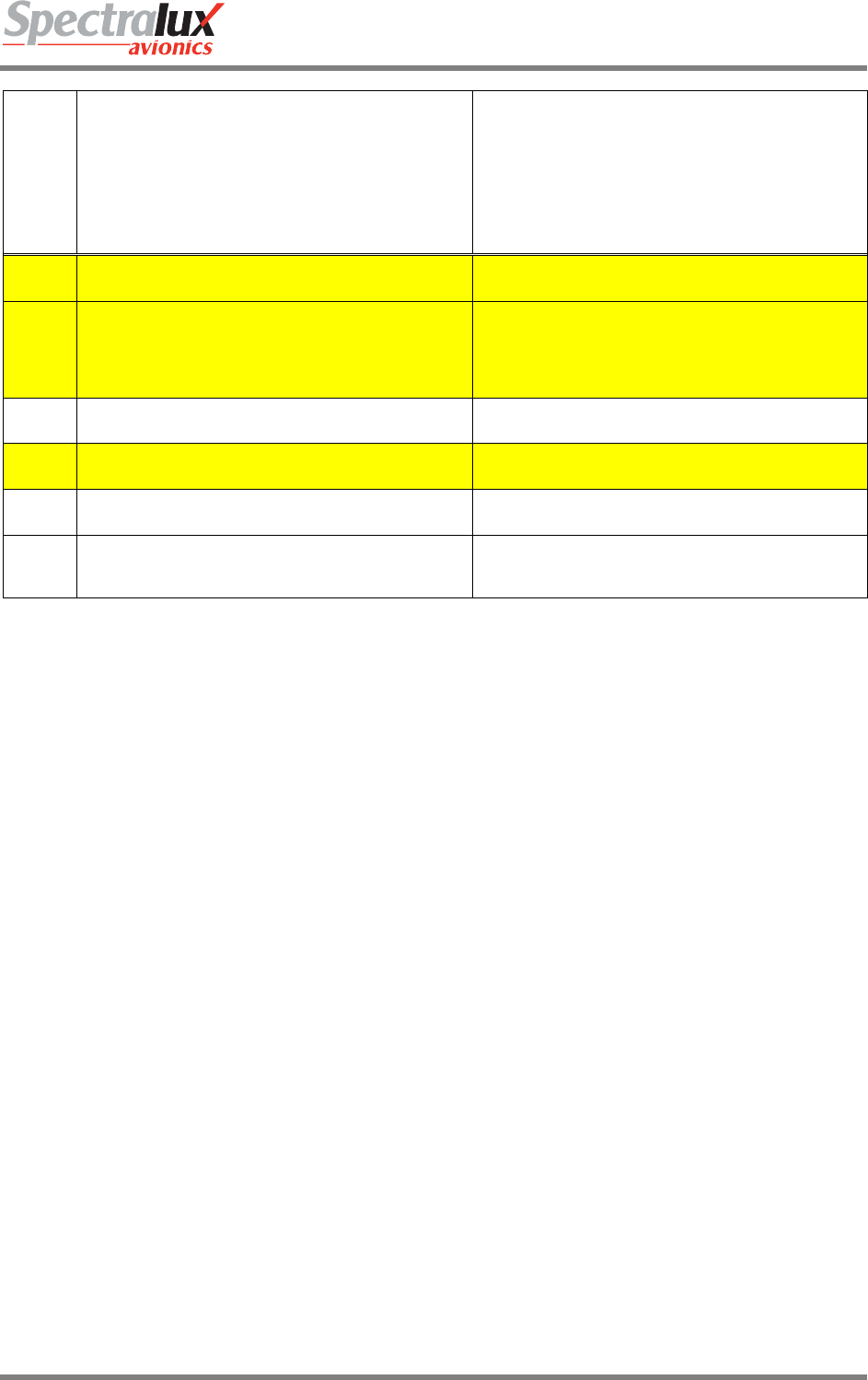
Dlink+CPDLC Users Guide
Document Number: UG-14114 Rev. - Page 196 of 201
Downlink
Message Element
Message Element Format Message Intent
106 PREFERRED LEVEL 25000FT PREFERRED LEVEL[level] - Notification of the preferred
level.
107
NOT AUTHORIZED NEXT DATA AUTHORITY
NOT AUTHORIZED NEXT DATA AUTHORITY – A
system-generated message sent to a ground system that
tries to connect to an aircraft when a current data
authority has not designated the ground system as the
NDA.
108 DE-ICING COMPLETE DE-ICING COMPLETE - Notification that de-icing action
has been completed.
109 TOP OF DESCENT 1237 TOP OF DESCENT [time] - Notification of the preferred
time to commence descent for approach.
110 TOP OF DESCENT XYZ TOP OF DESCENT [position] - Notification of the
preferred position to commence descent for approach.
111 TOP OF DESCENT 1200 XYZ
TOP OF DESCENT [time] [position] - Notification of the
preferred time and position to commence descent for
approach.

Dlink+CPDLC Users Guide
Document Number: UG-14114 Rev. - Page 197 of 201
8 Events
8.1 OOOI Events
The OOOI, (Out / Off / On / In) events provide a basic indication of the phase of a flight. Each event may
be set up, by the user, to provide information to an operational center as one or several down links.
8.1.1 Out Event
An Out Event is triggered when all of the following are true:
1. Breaks are OFF
2. All doors are CLOSED
3. OOOI STATE is INIT or RETURN.
4. The above conditions have existed for 5 consecutive seconds.
8.1.2 Off Event
An Off event is triggered when all of the following are true:
1. No weight on wheels
2. OOOI STATE is OUT.
3. The above conditions have existed for 5 consecutive seconds.
8.1.3 On Event
Event is triggered when all of the following are true:
1. There is weight on wheels
2. OOOI STATE is OFF.
3. The above conditions have existed for 5 consecutive seconds.
8.1.4 In Event
Event is triggered when all of the following are true:
1. Breaks are ON
2. One or more doors is open
3. OOOI STATE is ON.
4. The above conditions have existed for 5 consecutive seconds.
8.1.5 Out Return In Event
Event is triggered when all of the following are true:
1. Breaks are ON
2. One or more doors are open
3. OOOI STATE is OUT.
8.1.6 Reset Event
A Reset event is triggered when all of the following are true:
1. The flight complete timer expires.
2. OOOI_STATE is IN.
8.2 OOOI Initialize State
The Initialize state is entered when all of the following are true:
1. The Dlink+ w/CPDLC has recently powered up.
2. The OOOI STATE is IN
3. An OUT Event is triggered.
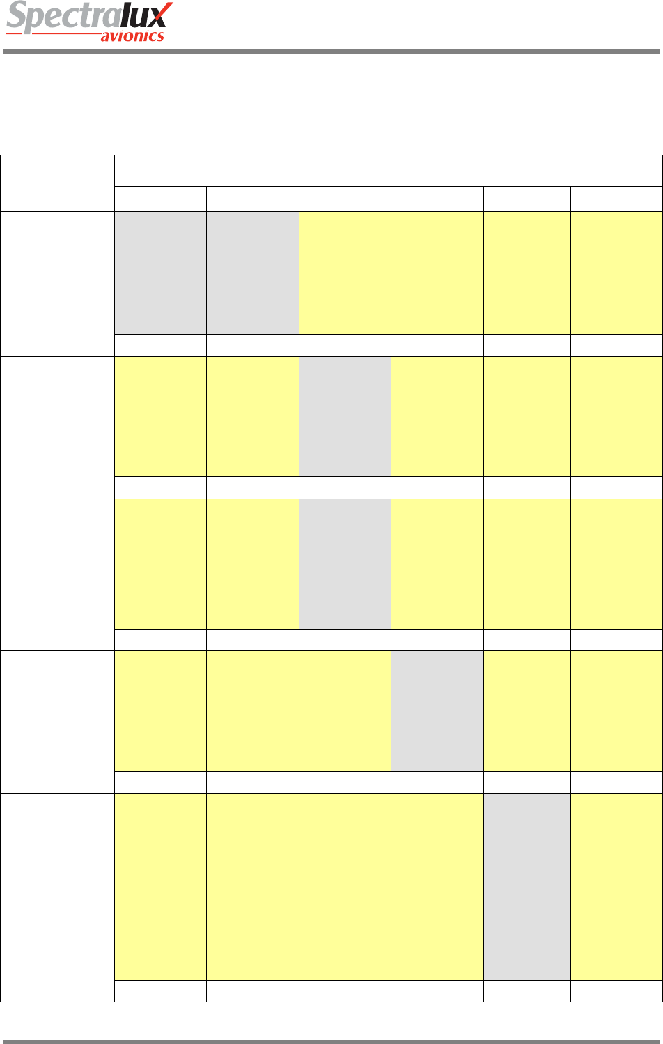
Dlink+CPDLC Users Guide
Document Number: UG-14114 Rev. - Page 198 of 201
EVENT
OOOI_STATE
INIT RETURN OUT OFF ON IN
OUT
Do the following:
1. Set Out of Gate
Time to current time.
2. Set OOOI_OUT
to TRUE.
3. Trigger all
downlinks
associated with the
OUT event.
Do the following:
1. Set Out of Gate
Time to current time
2. Set OOOI_OUT
to TRUE.
3. Trigger all
downlinks
associated with the
OUT event.
No Action No Action No Action No Action
OUT RETURN OUT OFF ON IN
OFF
No Action No Action
Do the following:
1. Set Off Ground
Time to current time.
2. Set OOOI_OFF to
TRUE.
3. Trigger all
downlinks
associated with the
OFF event.
No Action No Action No Action
INIT RETURN OFF OFF ON IN
OUT RETURN
IN
No Action No Action
Do the following:
1. Set Return TO
Gate Time to current
time.
2. Set OOOI_OUT
to FALSE.
3. Trigger all
downlinks
associated with the
RETURN event.
No Action No Action No Action
INIT RETURN RETURN OFF ON IN
ON
No Action No Action No Action
Do the following:
1. Set On Ground
Time to current time.
2. Set OOOI_ON to
TRUE.
3. Trigger all
downlinks
associated with the
ON event.
No Action No Action
INIT RETURN OUT ON ON IN
IN
No Action No Action No Action No Action
Do the following:
1. Set Into Gate
Time to current
time.
2. Set OOOI_IN to
TRUE.
3. Trigger all
downlinks
associated with the
IN event.
4. Start the flight
complete timer
with an expiration
value of 10
minutes.
No Action
INIT RETURN OUT OFF IN IN
Dlink+CPDLC Users Guide
Document Number: UG-14114 Rev. - Page 199 of 201
RESET
No Action No Action No Action No Action No Action
Do the following:
1. Reset following
data to its default:
Out of Gate Time,
Return To Gate
Time,
Off Ground Time,
On Ground Time,
Into Gate Time,
Origin Airport,
Flight Number,
Destination Airport,
2. Reset this OOOI
data to FALSE:
OOOI_OUT
OOOI_OFF
OOOI_ON
OOOI_IN
INIT RETURN OUT OFF ON INIT
Table 3 OOOI State Table

Dlink+CPDLC Users Guide
Document Number: UG-14114 Rev. - Page 200 of 201
9 Startup
9.1 Visual Indicators
During power on start up the Dlink+ w/ CPDLC will perform several power-on Built In Tests (BIT). You
will observe all annunciators becoming illuminated and remain so for approximately 10 seconds. This is
followed by the annunciators extinguishing and the blank display showing the splash screen. The splash
screen (see Splash Screen for a visual representation) will remain for approximately 5 seconds before
transitioning to the Main Menu. At this point the Dlink+ w/CPDLC will be ready for normal operation.
9.2 ACARS
Refer to section on ACARS Start up.
9.3 CPDLC
Refer to the section on CPDLC start up and logon (CM Logon)

Dlink+CPDLC Users Guide
Document Number: UG-14114 Rev. - Page 201 of 201
10 Shutdown
When the Dlink+ w/CPDLC shuts down or loses power for any reason messages in the message log will
be retained.
10.1 User-Initiated Reset
It is possible to reset the Dlink+ w/CPDLC from the keyboard, without removing power or repositioning a
breaker. By pressing and holding the “7”, “Z”, and “/” keys for 2 seconds will initiate a reset. The screen
will indicate as such.