SpiderCloud Wireless 8818C412 Universal Small Cell 8818 LTE/LTE Module User Manual Cisco USC 8718 8818 Installation Guide
SpiderCloud Wireless Universal Small Cell 8818 LTE/LTE Module Cisco USC 8718 8818 Installation Guide
User Manual

Revised: October 26, 2015,
Cisco USC 8718/8818 Dual-Mode Small Cell Module Installation
Before You Begin
The Cisco Universal Small Cell (USC) 8718 dual-mode small cell module provides either 3G or 4G cellular coverage in an indoor
environment where improved coverage and capacity is desired for cellular services. The USC 8818 small cell module provides LTE
cellular coverage on a software-selectable LTE band. The small cell modules are specifically designed to work with Cisco Aironet
3600/3700 series Wi-Fi access points (APs) or the USC 5030 small cell chassis. Each small cell module is capable of supporting
either Universal Mobile Telecommunications System (UMTS), where applicable, or Long Term Evolution (LTE) radio protocols in
a single platform, is 3GPP compliant and supports UMTS Release 7 and LTE Release 9 standards.
Each USC 8718 module can support either:
•up to 32 simultaneous UMTS voice and data channels, a peak downlink rate of 21 Mbps and a peak uplink rate of 5 Mbps
•up to 32 active LTE users per radio, a peak download rate of 100 Mbps, and a peak upload of 50 Mbps when used with 20 MHz
channel bandwidth
The USC 8818 is a dual-band, LTE-only, software-switchable module that can support up to 32 simultaneous LTE channels on either
LTE cell, a peak download rate of 100 Mbps, and uplink of 50 Mbps when used with 20 MHz channel bandwidth.
2
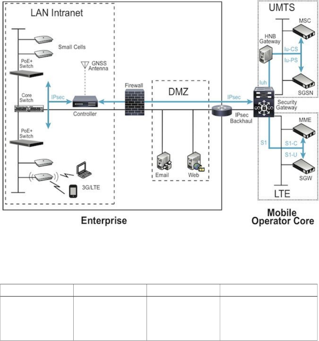
These small cell modules enable mobile operators to offer dedicated, in-building coverage and capacity for UMTS and LTE services.
They are managed by the Cisco USC 8088 controller installed in the enterprise.
Figure 1: Small Cell Relationship to Enterprise and Mobile Operator Core Networks
System Requirements
The various small cell modules are designed for use with the following hardware:
Table 1: Small Cell Modules and Supported Hardware
Supported HardwareMonitor BandsTransmit BandsSmall Cell Module
Aironet 3700 AP Rev 2
USC 5030
UMTS Bands 1, 8
LTE Bands 3, 7, 20
GSM 925-960 MHz and
1805-1880 MHz
UMTS Band 1
LTE Band 7
USC8718-M17-K9
3

Supported HardwareMonitor BandsTransmit BandsSmall Cell Module
Aironet 3600 AP
Aironet 3700 AP
USC 5030
UMTS Bands 2, 5
LTE Bands 2, 4
GSM 869-894 MHz
UMTS Band 2
LTE Band 4
USC 8718-M24-K9
Aironet 3600 AP
Aironet 3700 AP
USC 5030
UMTS Bands 1, 8
LTE Bands 3, 7, 20
GSM 925-960 MHz and
1805-1880 MHz
UMTS Band 1
LTE Band 3
USC8718-M13-K9
Aironet 3600 AP
Aironet 3700 AP
USC 5030
UMTS Bands 1, 5, 8
LTE Bands 1, 3, 7
GSM 925-960MHz and
1805-1880MHz
LTE Band 1
LTE Band 3
USC8818-C13-K9
USC 8000 series modules are compatible with the Cisco Aironet –i variants with internal antennas when
they are ceiling mounted (for example, Cisco 3700i). They are not compatible with Cisco Aironet –e
variants when horizontal mounted or with external antennas (for example, Cisco 3700e).
Note
The small cell modules are not designed for use with other access points. The small cell modules are managed by the Cisco USC
8088 controller installed in the enterprise. The controller has two variants, one for high capacity and another for low capacity. These
two variants differ in relation to the access modules installed in the hardware.
Software Requirements
The small cell modules are supported on Release 4.1.5 and above.
The small cell modules are compatible with software release 8.1 MR or beyond of the wireless LAN controller. Please verify that
the proper release version is available on the wireless LAN controller at the time of installation.
Power Considerations
Installation of your small cell module can require an additional 10 watts to power the Cisco Aironet access point. With a small cell
module installed, the access point requires the full Power over Ethernet Plus (PoE+) of 25.5 Watts at the egress switch port and a
cable run of less than 300 feet (100 meters).
Power options for the access point include:
•IEEE 802.3at POE+ 25.5 W delivered from the upstream Ethernet switch
•Cisco 3600 Series Power Injector (AIR-PWRINJ4=)
•Cisco 3600 Series local power supply (AIR-PWR-B=)
The small cell module has a power limit circuitry that shuts down the module if it draws more power than allowed.
4
Installation Considerations
Install your small cell:
•in a central location, in an area where people are most likely to make calls
•away from windows, to avoid the signal leaking outside or external signals leaking in
•in an open area with airflow; not in a closed cabinet which reduces the signal strength
•at least 5 meters (16 feet) from an external wall. This distance maximizes indoor coverage and minimizes RF leakage outside
the building. Refer to the Cisco USC 8000 Series Deployment Planning Guide for Dual-Mode Systems and Cisco USC 8000
Series Deployment Planning Guide for LTE Systems for more information about small cell placement.
If you have thick internal walls, or metal, fire or rotating doors, plan to place units at either side of the obstruction at a distance shorter
than 49 feet (15 m). Install a unit across from a corner to provide coverage on both sides of the corner.
For more information, refer to the "Cisco Aironet AP Module for Wireless Security and Spectrum Intellgence (WSSI) Deployment
Guide" at the following URL: http://www.cisco.com/en/US/products/ps11983/ products_tech_note09186a0080bed15d.shtml.
Install Your Small Cell Module
The small cell module can be installed in either a Cisco Aironet 3600 series access point (AP), a Cisco Aironet 3700 series AP or the
Cisco USC 5030 chassis according to these instructions:
5
Procedure
Step 1 Remove the module from the packaging.
Step 2 Power down the access point if you are installing the small cell module into an operational access point.
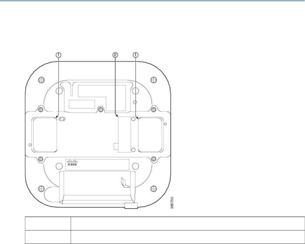
Step 3 Peel off the label from the back of the AP to reveal the module port connector.
Figure 2: Backside of Cisco Aironet 3600 Access Point
Openings for module's antennas1
Label covering port connector2
6
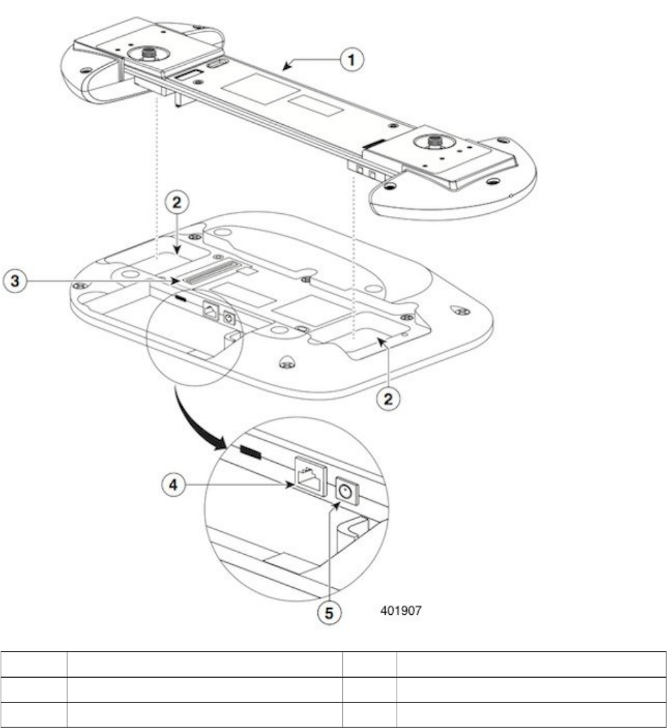
Step 4 Align the module connector with the connector on the back of the AP or USC 5030 chassis such that the male and female
100-pin mezzanine connectors mate.
Figure 3: Installing Module in the Cisco 5030 Chassis
10/100 Base-T Ethernet port4Small cell module1
Power port for DC power source5Openings for module antennas2
Port connector3
Step 5 Hold both units in your hands and firmly join the module to the AP or USC 5030 chassis to fully attach the two units.
7

Because the small cell module is thicker than the AP, you must hold both units together when attaching
them.
Note
Step 6 Screw down the thumb screws on the module.
If the screws are not tightened, the module will not be recognized and may not operate correctly. Make sure not
to over-tighten the screws; they should be only hand-tightened.
Note
Step 7 Power up the access point.
Step 8 If necessary, mount the access point or USC 5030 chassis, with the small cell module installed, using the universal bracket
(AIR-AP-BRACKET-2).
The universal bracket works with electrical boxes, can be used for wall mounting, and adapts to ceiling installations.
It leaves a larger gap between the mounting surface and the access point, which allows space for the small cell
module.
For more information, refer to "Access Point Mounting Instructions" at the following URL:
http://www.cisco.com/en/US/docs/woreless/access_point/mounting/guide/apmount.html
Note
8
Boot Sequence and USC 8088 Controller Communication
On initial boot, the small cell module performs the following boot sequence. When finished, the module is reachable.
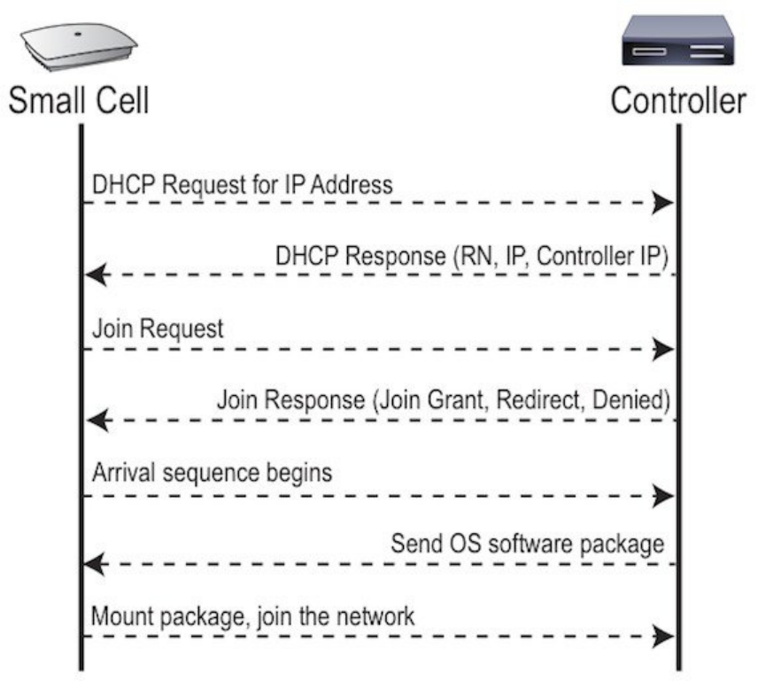
Figure 4: Small Cell Boot Sequence
Boot Sequence:
1When the small cell is powered on, the device sends a DHCP Request to the controller DHCP server to get IP information. The
DHCP server is configured on the controller to respond only to DHCP requests from Cisco Systems small cells. Refer to the Cisco
USC 8000 Series OS Administrator Guide for more information about the controller DHCP server configuration.
2The server responds with the IP addresses of the small cell and the controller (the master of the small cell).
3Using its own IP address, the small cell sends a Join Request message to the controller. The small cell seeks to join the cellular
network.
4The controller responds with a Join Response message indicating whether the small cell is allowed to join the network or not.
9

5The arrival sequence begins. The controller sends the software image to the small cell.
6The small cell boots up the received software package.
7The small cell establishes an IPsec tunnel with the controller. Based upon the radio configuration, the small cell loads the appropriate
protocol elements and joins the network.
Small Cell LED Boot Sequence
The small cell state machine is sequential and progresses in the following order:
State 0 -> State 1 -> State 2 -> State 3 -> State 4 -> State 5
A normal boot sequence transitions through all these states sequentially and the LED state transitions accordingly. If the small cell
fails to transition to the next state, the system restarts the boot sequence, starting with State 0. You can determine the progress during
the booting stages by observing the LED color transitions. On failure, the last LED state will display the state that encountered the
failure. This table shows the small cell boot sequence and corresponding LED behavior:
Table 2: Small Cell LED Boot Sequence
Possible Failures and ActionsDescriptionLED ColorState
Short lived state; small cell should transition
to the next state immediately and should not
remain in this state indefinitely.
Flashing Green is also used to
indicate a small cell that has been
administratively disabled. This can
be determined from the CLI.
Note
Initial state on startup. The small cell
bootup is controlled by firmware in this
state. It goes through a lamp test in this
state, meaning that it cycles through all
LED colors.
Flashing Green0. Power
On/Reset
No DHCP Response, IP Address not
allocated.
Check cabling, DHCP Server configuration.
Small cell sends DHCP Request.
The small cell moves to the next state (State
2) upon receiving a DHCP response and an
IP Address.
Solid Red1. DHCP
No IP reachability to the controller.
Check IP network between small cell and
controller for routing issues.
The small cell has an IP Address and sends
a UDP Join request to the Serving
controller.
The small cell moves to the next state (State
3) upon getting a JOIN GRANT from the
controller.
Solid Blue2. Join
Failure to download TFTP image.
Check firewall between small cell and
controller.
The small cell proceeds next to download
the operating system image from the
controller.
The small cell moves to the next state (State
4) after the image has been downloaded.
Flashing Blue3. TFTP
10
Possible Failures and ActionsDescriptionLED ColorState
Failure to start the operating system.
This normally points to a software/build
issue. Please contact Cisco support.
The small cell loads the operating system
and starts the default platform applications.
The small cell moves to the next state (State
5) when it establishes connectivity with the
service node.
Flashing Green4. Operating
System Booting
Any subsequent state transitions can now be
tracked from events and logs on the
controller.
The operating system is running. The small
cell continues the startup sequence, but is
now controlled by the controller. The
operating system is up and running on the
small cell.
Solid Green5. Running
Verify Your Small Cell Module Installation
After the small cell module is installed and powered up, it takes approximately one minute for the module to perform the boot sequence
and be reachable by the controller. Take note of the initialization sequence by noting the color and activity of the LEDs on either side
of the module. The module is ready to use when the LEDs change to solid green.
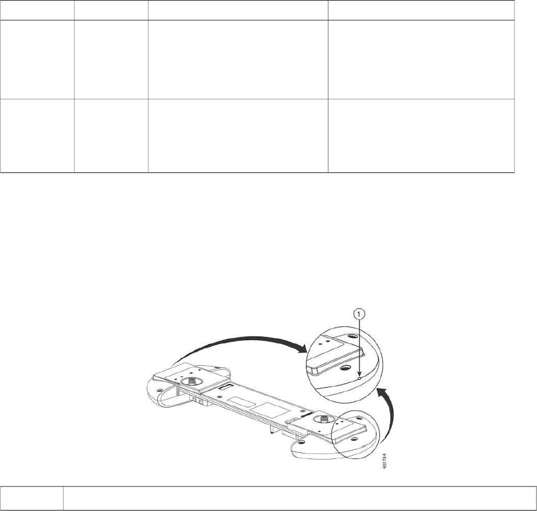
Figure 5: Cisco Small Cell Module
LED—the same LED indication displays on both sides of the module
1
The LED display is active by default, but can be deactivated in light-sensitive environments as needed. Even when the display is
disabled, the LED will be lighted during the following conditions:
•while the small cell is booting
•if the small cell or cell is in fault state
•if there is an active emergency call
•if the locate small cell feature is active
11
•if the follow IMSI feature is active
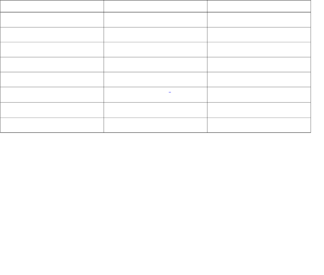
This table shows the default LED behavior of the USC 8718:
Table 3: Cisco USC 8718 LED Behavior
Flash RateStatusLED
Approximately ½ second on, 1½ sec. offAdministratively disabledGreen: slow flashing
Approximately 1.4 second on/off cycleBootingGreen: fast flashing
OperationalGreen: solid
FaultRed: solid
Approximately 1 second on/off cycleOne or more emergency calls activeRed: fast flashing
Approximately 1 second on/off cycleLocate small cell enabled1
Blue: fast flashing
Follow IMSI enabled1
Blue: solid
Powered off or LED disabledOff
1Refer to the Cisco USC 8000 Series OS Administrator Guide for information about "locate small cell" and "follow IMSI".
To disable the LED display:
1From the Configuration Mode, use the set System RadioNode LED DefaultMode Dark command.
2To verify the configuration, use the show System RadioNode LED command.
show System RadioNode LED
DefaultMode Dark;
To re-enable the LED display:
1From the Configuration Mode, use the set System RadioNode LED DefaultMode Standard command.
2To verify the configuration, use the show System RadioNode LED command.
show System RadioNode LED
DefaultMode Standard;
12
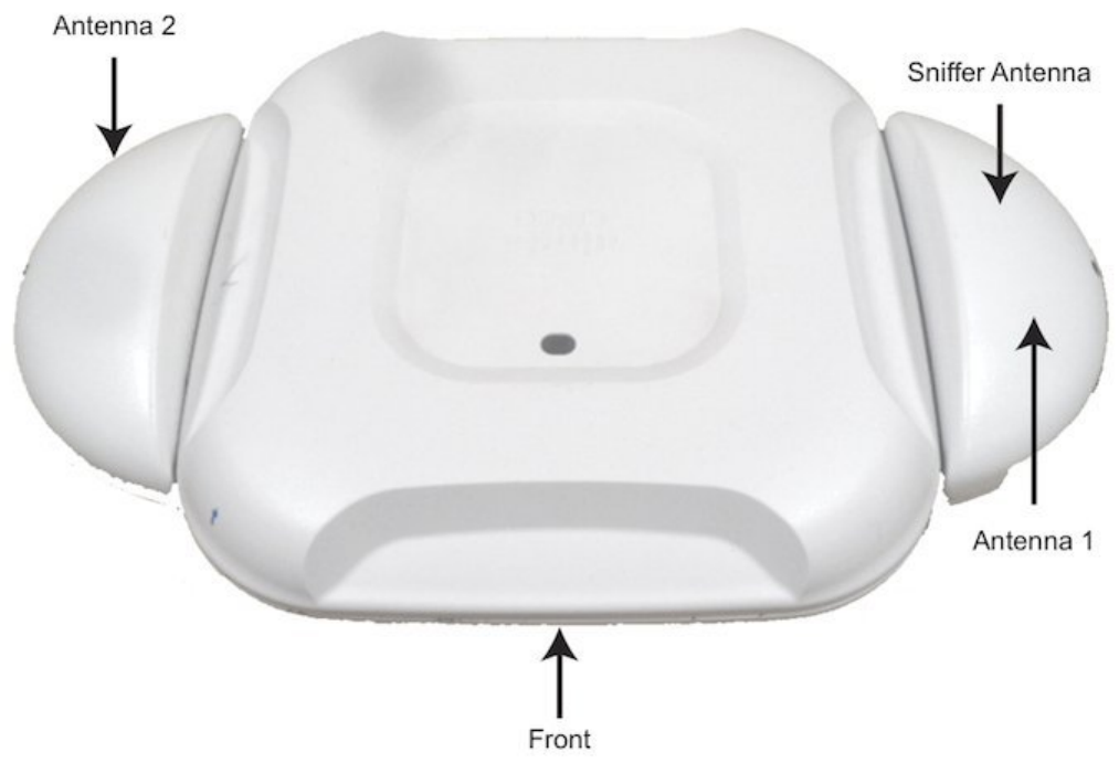
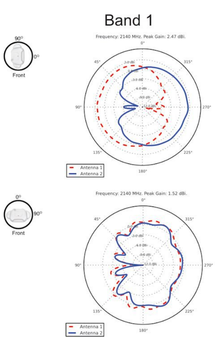
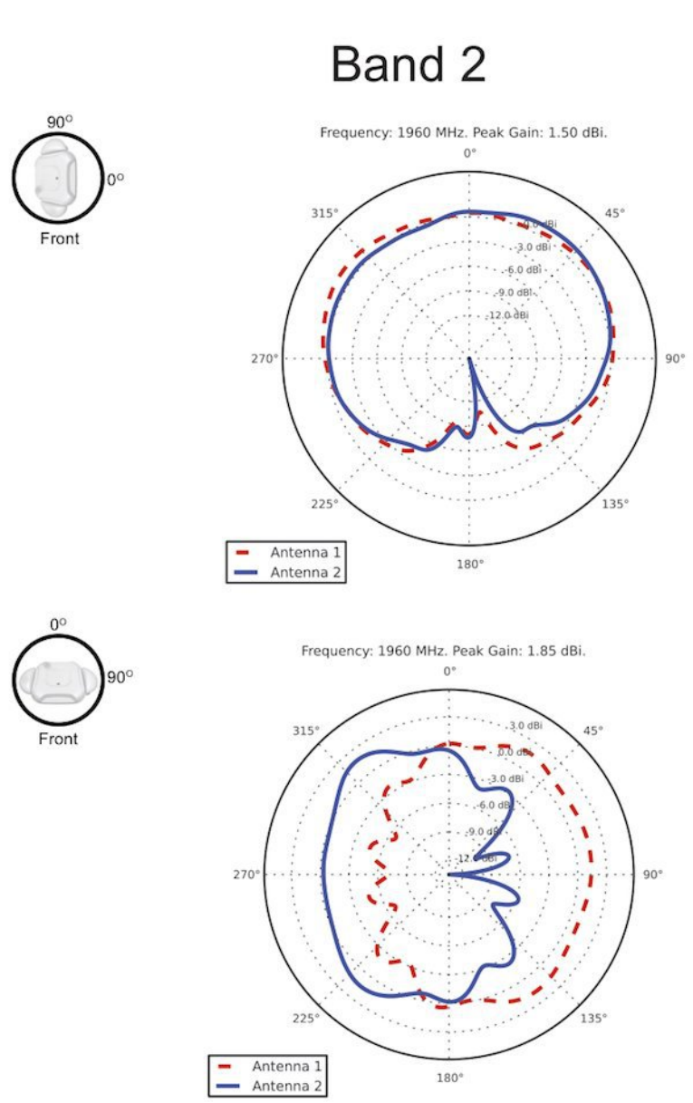
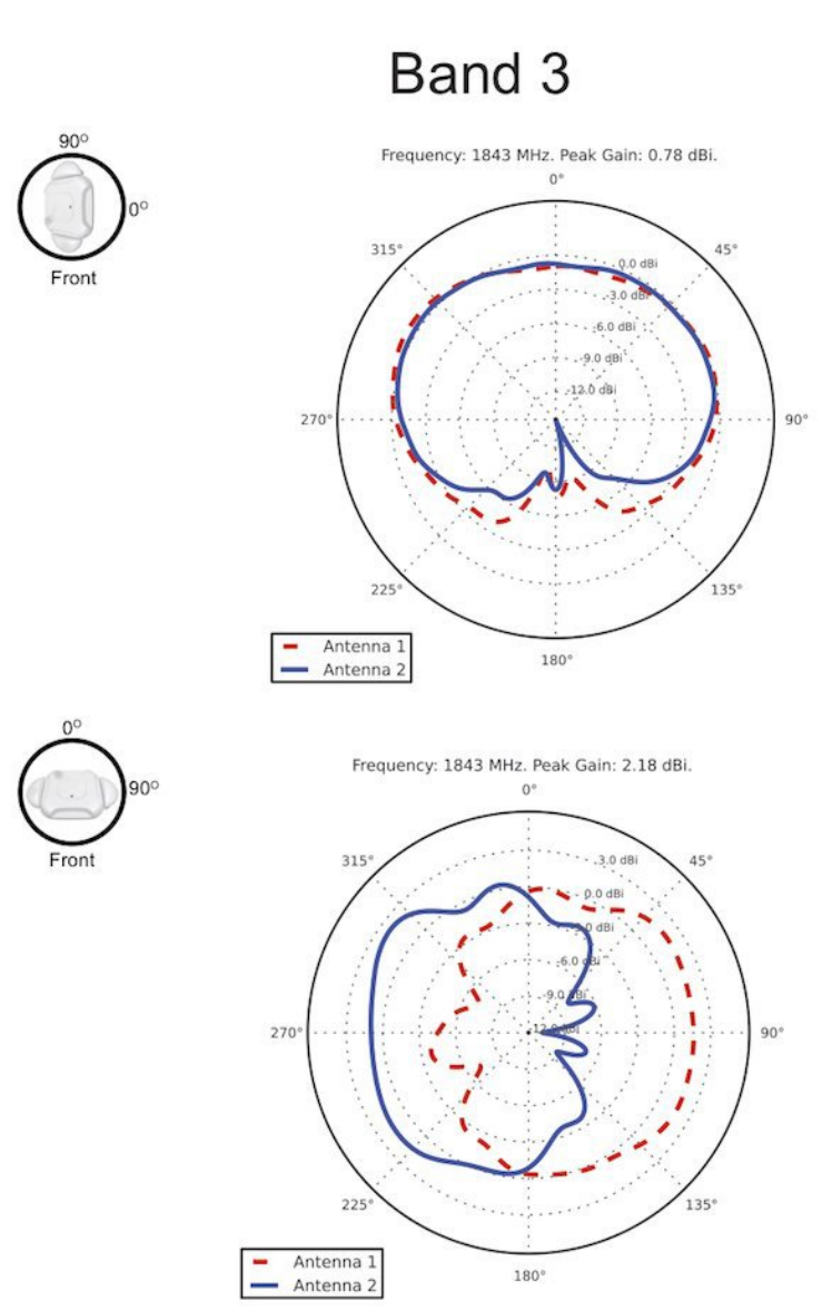
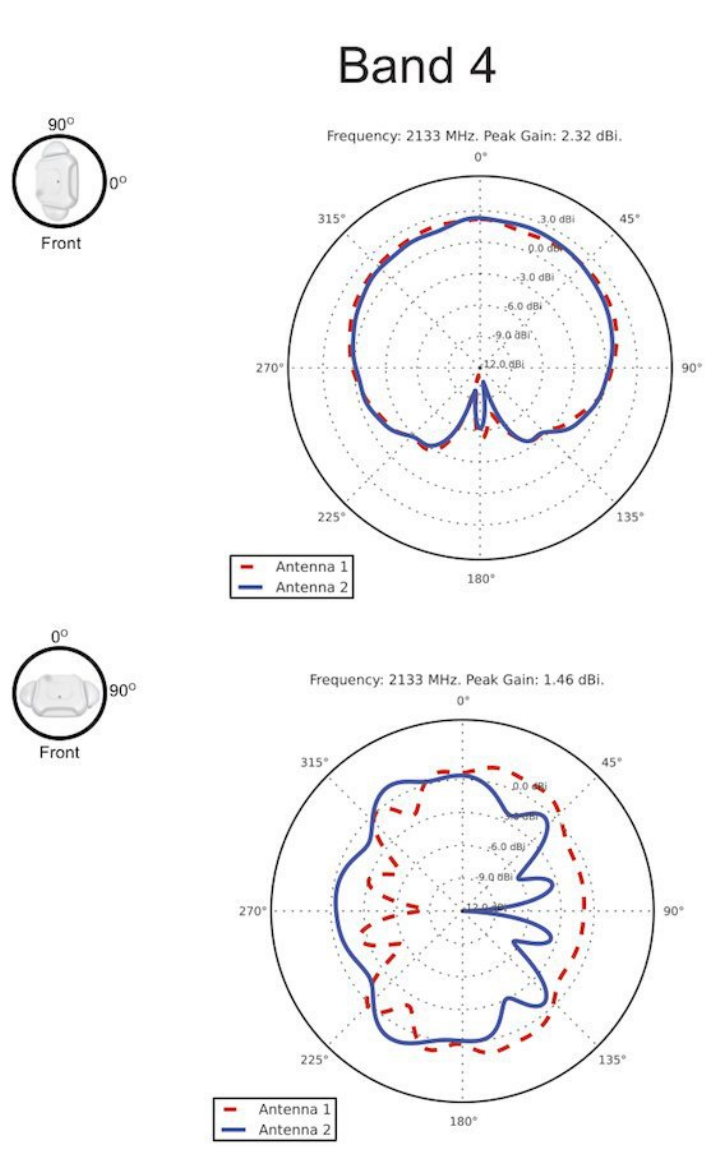
Antenna Patterns
This illustration shows the USC 8718 antenna locations when situated on the AP. Refer to the orientation when assessing the radio
band patterns in this section.
Figure 6: Orientation and Antenna Locations
13
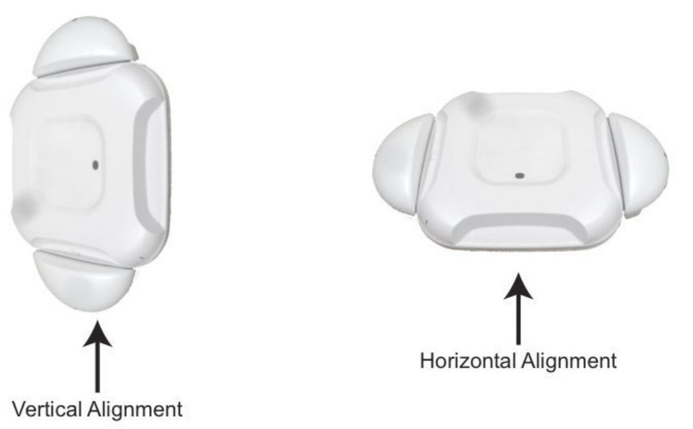
This illustration shows the vertical and horizontal alignment positions used in the band patterns in this section.
Figure 7: Vertical and Horizontal Alignment Orientations
14
15
16
17
18

Safety Instructions
Translated versions of the following safety warnings are provided in the Regulatory Compliance and Safety Information document
for this product, located on Cisco.com.
Statement 1071—Warning DefinitionWarning
IMPORTANT SAFETY INSTRUCTIONS
This warning symbol means danger. You are in a situation that could cause bodily injury. Before you work
on any equipment, be aware of the hazards involved with electrical circuitry and be familiar with standard
practices for preventing accidents. Use the statement number provided at the end of each warning to locate
its translation in the translated safety warnings that accompanied this device.
SAVE THESE INSTRUCTIONS
Warning
IMPORTANTES INFORMATIONS DE SÉCURITÉ
Ce symbole d'avertissement indique un danger. Vous vous trouvez dans une situation pouvant entraîner
des blessures ou des dommages corporels. Avant de travailler sur un équipement, soyez conscient des
dangers liés aux circuits électriques et familiarisez-vous avec les procédures couramment utilisées pour
éviter les accidents. Pour prendre connaissance des traductions des avertissements figurant dans les consignes
de sécurité traduites qui accompagnent cet appareil, référez-vous au numéro de l'instruction situé à la fin
de chaque avertissement.
CONSERVEZ CES INFORMATIONS
Attention
Statement 1004—Installation InstructionsWarning
Read the installation instructions before connecting the system to the power source.Warning
Avant de brancher le système sur la source d'alimentation, consulter les directives d'installation.Attention
Statement 1074—Comply with Local and National Electrical CodesWarning
Installation of the equipment must comply with local and national electrical codes.Warning
L'équipement doit être installé conformément aux normes électriques nationales et locales.Attention
19
Statement 1005—Circuit BreakerWarning
This product relies on the buildings installation for short-circuit (overcurrent) protection. Ensure that the
protective device is rated not greater than: 10-15A, 100-240VAC
Warning
Pour ce qui est de la protection contre les courts-circuits (surtension), ce produit dépend de l'installation
électrique du local. Vérifiez que le courant nominal du dispositif de protection n'est pas supérieur à: 10-15A,
100-240VAC
Attention
Statement 332—Antenna Installation WarningWarning
In order to comply with FCC radio frequency (RF) exposure limits, antennas should be located at a minimum
of 7.9 inches (20 cm) or more from the body of all persons.
Warning
Pour se conformer aux limites d'exposition à la fréquence radio préconisées par la FCC (Federal
Communications Commission), les antennes doivent se situer à un minimum de 20 cm de toute personne.
Attention
Statement 12—Power Supply Disconnection WarningWarning
Before working on a chassis or working near power supplies, unplug the power cord on AC units; disconnect
the power at the circuit breaker on DC units.
Warning
Avant de travailler sur un châssis ou à proximité d'une alimentation électrique, débrancher le cordon
d'alimentation des unités en courant alternatif ; couper l'alimentation des unités en courant continu au
niveau du disjoncteur.
Attention
20
Statement 2017—Class A Notice for FCC
Modifying the equipment without Ciscos authorization may result in the equipment no longer complying
with FCC requirements for Class A digital devices. In that event, your right to use the equipment may be
limited by FCC regulations, and you may be required to correct any interference to radio or television
communications at your own expense.
This equipment has been tested and found to comply with the limits for a Class A digital device, pursuant
to Part 15 of the FCC Rules. These limits are designed to provide reasonable protection against harmful
interference when the equipment is operated in a commercial environment. This equipment generates,
uses, and can radiate radio frequency energy and, if not installed and used in accordance with the instruction
manual, may cause harmful interference to radio communications. Operation of this equipment in a
residential area is likely to cause harmful interference in which case users will be required to correct the
interference at their own expense.
Warning
Caution The fasteners you use to mount the unit on a ceiling must be capable of maintaining a minimum pullout
force of 20 lbs (9 kg) and must use all 4 indented holes on the mounting bracket.
Caution
Les attaches que vous utilisez pour installer le châssis au plafond doivent être capables de résister à une
force d'arrachement minimale de 9 kg (20 lb) et doivent utiliser les quatre orifices de montage prévus sur
le support de montage.
Mise en garde
Caution This product and all interconnected equipment must be installed indoors within the same building, including
the associated LAN connections as defined by Environment A of the IEEE 802.af Standard.
Caution
Conformément à la définition de l'environnement A de la norme IEEE 802.af, ce produit et tout l'équipement
interconnecté, y compris les connexions LAN associées, doivent être installés à l'intérieur d'un même
bâtiment.
Mise en garde
Statement 287—Declaration of Conformity to R&TTE Directive 1999/5/EC for the European Community,
Switzerland, Norway, Iceland and Liechtenstein
This equipment is in compliance with the essential requirements and other relevant provisions of Directive
1999/5/EC.
Note
21
This product is suitable for operation in a building's environmental air space, such as above suspended
ceilings, in accordance with Section 300-22(C) of the National Electrical Code (NEC) and Sections 2-128,
12-010(3) and 12-100 of the Canadian Electrical Code, Part 1, C22.1.
Peut être utilisé dans des gaines transportant de l'air traité, conformément à la section 300-22(C) du National
Electrical Code et aux articles 2l-128, 12-010(3) et 12-100 du Code Canadien de l'électricité, Premiére
partie, CSA C22.1.
Note
This Class [A/B] digital apparatus complies with Canadian ICES-003.
Cet appareil numérique de la classe [A/B] est conforme à la norme NMB-003 du Canada.
Note
Statement 8007—CE Mark for Class-II Radio EquipmentNote
Use only with listed ITE equipment.Note
If you require assistance installing or operating your small cell, contact customer support.
For warranty information, refer to: http://www.cisco-servicefinder.com/WarrantyFinder.aspx
22
Cisco and the Cisco logo are trademarks or registered trademarks of Cisco and/or its affiliates in the U.S. and other countries. To view a list of Cisco trademarks, go to this URL: http://
www.cisco.com/go/trademarks. Third-party trademarks mentioned are the property of their respective owners. The use of the word partner does not imply a partnership
relationship between Cisco and any other company. (1110R)
©2015 Cisco Systems, Inc. All rights reserved.

Europe HeadquartersAsia Pacific HeadquartersAmericas Headquarters
Cisco Systems International BV
Amsterdam, The Netherlands
Cisco Systems (USA) Pte. Ltd.
Singapore
Cisco Systems, Inc.
San Jose, CA 95134-1706
USA
Cisco has more than 200 offices worldwide. Addresses, phone numbers, and fax numbers are listed on the
Cisco Website at www.cisco.com/go/offices.